Embed Size (px)
Citation preview
User’s Manual
MultiSync X464UNMultiSync X464UNVMultiSync X554UN
MultiSync X554UNS
Index
Declaration of conformity .............................................................................................................................. English-1Important Information ................................................................................................................................... English-2
WARNING ....................................................................................................................................... English-2CAUTION ........................................................................................................................................ English-2
Safety Precautions, Maintenance & Recommended Use............................................................................. English-3Contents ....................................................................................................................................................... English-4Installation .................................................................................................................................................... English-5
Attaching Mounting Accessories ..................................................................................................... English-6Parts Name and Functions ........................................................................................................................... English-8
Control Panel .................................................................................................................................. English-8Terminal Panel ................................................................................................................................ English-9Wireless Remote Control (Optional) ............................................................................................... English-10Operating Range for the Optional Remote Control ......................................................................... English-11
Setup ............................................................................................................................................................ English-12Connections ................................................................................................................................................. English-14
Wiring Diagram ............................................................................................................................... English-14Connecting a Personal Computer ................................................................................................... English-15Connecting a DVD Player or Computer with HDMI out .................................................................. English-15Connecting a Computer with DisplayPort ....................................................................................... English-15
Basic Operation ............................................................................................................................................ English-16Power ON and OFF Modes ............................................................................................................ English-16Power Indicator ............................................................................................................................... English-17Using Power Management ............................................................................................................. English-17Selecting a video source ................................................................................................................. English-17Picture Aspect ................................................................................................................................. English-17Information OSD ............................................................................................................................. English-18Picture Mode ................................................................................................................................... English-18
OSD (On-Screen-Display) Controls.............................................................................................................. English-19PICTURE ........................................................................................................................................ English-20ADJUST .......................................................................................................................................... English-20AUDIO ............................................................................................................................................ English-21SCHEDULE .................................................................................................................................... English-22PIP .................................................................................................................................................. English-22OSD ................................................................................................................................................ English-23MULTI DISPLAY ............................................................................................................................. English-23DISPLAY PROTECTION ................................................................................................................ English-25EXTERNAL CONTROL ................................................................................................................... English-25ADVANCED OPTION1 ................................................................................................................... English-26ADVANCED OPTION2 ................................................................................................................... English-28
Remote Control Function .............................................................................................................................. English-30Multiple Monitors Connection ....................................................................................................................... English-31Controlling the LCD monitor via RS-232C Remote Control.......................................................................... English-32Controlling the LCD monitor via LAN Control ................................................................................................ English-34
Connecting to a Network ................................................................................................................ English-34Network Setting by Using an HTTP Browser .................................................................................. English-34
POINT ZOOM ............................................................................................................................................... English-43PROOF OF PLAY ......................................................................................................................................... English-43INTELLIGENT WIRELESS DATA ................................................................................................................. English-44Features ....................................................................................................................................................... English-45Troubleshooting ............................................................................................................................................ English-46Specifi cations - X464UN .............................................................................................................................. English-47Specifi cations - X464UNV ............................................................................................................................ English-48Specifi cations - X554UN .............................................................................................................................. English-49Specifi cations - X554UNS ............................................................................................................................ English-50Pin Assignment ............................................................................................................................................. English-51Manufacturer’s Recycling and Energy Information ....................................................................................... English-52
English-1
Eng
lishDeclaration of conformity
FCC Information1. Use the attached specifi ed cables with the MultiSync X464UN (X464UN)/MultiSync X464UNV (X464UNV)/MultiSync X554UN
(X554UN)/MultiSync X554UN (X554UN(C))/MultiSync X554UNS (X554UNS) color display so as not to interfere with radio and television reception.
(1) Please use the supplied power cord or equivalent to ensure FCC compliance. (2) Please use a good quality shielded video signal cable. Use of other cables and adapters may cause interference with radio and television reception.2. This equipment has been tested and found to comply with the limits for a class A digital device, pursuant to Part 15 of the
FCC Rules. These limits are designed to provide reasonable protection against harmful interference when the equipment is operated in a commercial environment. This equipment generates, uses, and can radiate radio frequency energy and, if not installed and used in accordance with the instruction manual, may cause harmful interference to radio communications. Operation of this equipment in a residential area is likely to cause harmful interference in which case the user will be required to correct the interference at his own expense.
If necessary, the user should contact the dealer or an experienced radio/television technician for additional suggestions. The user may fi nd the following booklet, prepared by the Federal Communications Commission, helpful: “How to Identify and Resolve Radio-TV Interference Problems.” This booklet is available from the U.S. Government Printing Offi ce, Washington, D.C., 20402, Stock No. 004-000-00345-4.
Windows is a registered trademark of Microsoft Corporation. NEC is a registered trademark of NEC Corporation. OmniColor is a registered trademark of NEC Display Solutions Europe GmbH in the countries of EU and Switzerland.DisplayPort and DisplayPort Compliance Logo are trademarks owned by the Video Electronics Standards Association. All other brands and product names are trademarks or registered trademarks of their respective owners.
HDMI, the HDMI logo and High-Defi nition Multimedia Interface are trademarks or registered trademarks of HDMI Licensing LLC in the United States and other countries.
Trademark PJLink is a trademark applied for trademark rights in Japan, the United States of America and other countries and areas.
CRESTRON and ROOMVIEW are registered trademarks of Crestron Electronics, Inc. in the United States and other countries.
GPL/LGPL Software LicensesThe product includes software licensed under GNU General Public License (GPL), GNU Lesser General Public License (LGPL), and others.For more information on each software, see “readme.pdf” inside the “about GPL&LGPL” folder on the supplied CD-ROM.
English-2
Important Information
TO PREVENT FIRE OR SHOCK HAZARDS, DO NOT EXPOSE THIS UNIT TO RAIN OR MOISTURE. ALSO, DO NOT USE THIS UNIT’S POLARIZED PLUG WITH AN EXTENSION CORD RECEPTACLE OR OTHER OUTLETS UNLESS THE PRONGS CAN BE FULLY INSERTED.
REFRAIN FROM OPENING THE CABINET AS THERE ARE HIGH VOLTAGE COMPONENTS INSIDE. REFER SERVICING TO QUALIFIED SERVICE PERSONNEL.
WARNING
CAUTION: TO REDUCE THE RISK OF ELECTRIC SHOCK, MAKE SURE POWER CORD IS UNPLUGGED FROM WALL SOCKET. TO FULLY DISENGAGE THE POWER TO THE UNIT, PLEASE DISCONNECT THE POWER CORD FROM THE AC OUTLET. DO NOT REMOVE COVER (OR BACK). NO USER SERVICEABLE PARTS INSIDE. REFER SERVICING TO QUALIFIED SERVICE PERSONNEL.
This symbol warns user that uninsulated voltage within the unit may have suffi cient magnitude to cause electric shock. Therefore, it is dangerous to make any kind of contact with any part inside this unit.
This symbol alerts the user that important literature concerning the operation and maintenance of this unit has been included. Therefore, it should be read carefully in order to avoid any problems.
CAUTION
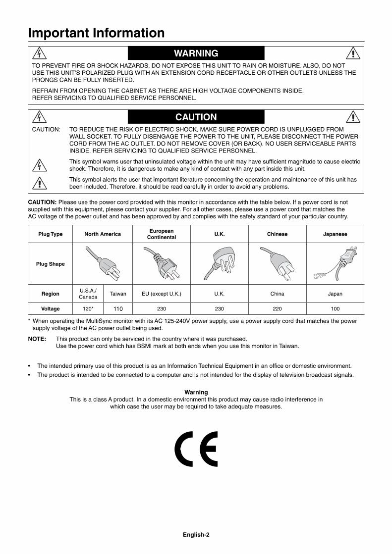
CAUTION: Please use the power cord provided with this monitor in accordance with the table below. If a power cord is not supplied with this equipment, please contact your supplier. For all other cases, please use a power cord that matches the AC voltage of the power outlet and has been approved by and complies with the safety standard of your particular country.
Plug Type North AmericaEuropean
ContinentalU.K. Chinese Japanese
Plug Shape
RegionU.S.A./Canada
Taiwan EU (except U.K.) U.K. China Japan
Voltage 120* 110 230 230 220 100
* When operating the MultiSync monitor with its AC 125-240V power supply, use a power supply cord that matches the power supply voltage of the AC power outlet being used.
NOTE: This product can only be serviced in the country where it was purchased.Use the power cord which has BSMI mark at both ends when you use this monitor in Taiwan.
• The intended primary use of this product is as an Information Technical Equipment in an offi ce or domestic environment.
• The product is intended to be connected to a computer and is not intended for the display of television broadcast signals.
WarningThis is a class A product. In a domestic environment this product may cause radio interference in
which case the user may be required to take adequate measures.
English-3
Eng
lish
FOR OPTIMUM PERFORMANCE, PLEASE NOTE THE FOLLOWING WHEN SETTING UP AND USING
THE MULTI-FUNCTION MONITOR:
• DO NOT OPEN THE MONITOR. There are no user serviceable parts inside and opening or removing covers may expose you to dangerous shock hazards or other risks. Refer all servicing to qualifi ed service personnel.
• Do not spill any liquids into the cabinet or use your monitor near water.
• Do not insert objects of any kind into the cabinet slots, as they may touch dangerous voltage points, which can be harmful or fatal or may cause electric shock, fi re or equipment failure.
• Do not place any heavy objects on the power cord. Damage to the cord may cause shock or fi re.
• Do not place this product on a sloping or unstable cart, stand or table, as the monitor may fall, causing serious damage to the monitor.
• Do not mount this product face up, face down or upside down for an extended period of time as it may cause permanent damage to the screen.
• The power supply cord you use must have been approved by and comply with the safety standards of your country. (Type H05VV-F 3G 1mm2 should be used in Europe)
• In UK, use a BS-approved power cord with molded plug having a black (13A) fuse installed for use with this monitor.
• Do not place any objects onto the monitor and do not use the monitor outdoors.
• Do not bend, crimp or otherwise damage the power cord.
• If glass is broken, handle with care.
• Do not cover vent on monitor.
• Do not use monitor in high temperature, humid, dusty, or oily areas.
• If monitor or glass is broken, do not come in contact with the liquid crystal and handle with care.
• Allow adequate ventilation around the monitor, so that heat can properly dissipate. Do not block ventilated openings or place the monitor near a radiator or other heat sources. Do not put anything on top of the monitor.
• The power cable connector is the primary means of detaching the system from the power supply. The monitor should be installed close to a power outlet, which is easily accessible.
• Do not move or mount this product by hanging a rope or wire to the backside handle.Do not mount or secure this product by using the backside handle. It may fall and cause personal injury.
• Handle with care when transporting. Save packaging for transporting.
• If using the cooling fan continuously, it is recommended to wipe holes clean a minimum of once a month.
• Please clean the holes of back cabinet to reject dirt and dust at least once a year because of set reliability.
• When using a LAN cable, do not connect to a peripheral device with wiring that might have excessive voltage.
• Do not use monitor under rapid temperature and humidity change condition or avoid cold air from air-conditioning outlet directly, as it may shorten the lifetime of the monitor or cause condensation. If condensation happens, let the monitor stand unplugged until there is no condensation.
Connecting to a TV*
• Cable distribution system should be grounded (earthed) in accordance with ANSI/NFPA 70, the National Electrical Code (NEC), in particular Section 820.93, Grounding of Outer Conductive Shield of a Coaxial Cable.
• The screen of the coaxial cable is intended to be connected to earth in the building installation.
Immediately unplug your monitor from the wall outlet and refer servicing to qualifi ed service personnel under the following conditions:
• When the power supply cord or plug is damaged.
• If liquid has been spilled, or objects have fallen into the monitor.
• If the monitor has been exposed to rain or water.
• If the monitor has been dropped or the cabinet damaged.
• If you notice any structural damage such as cracks or unnatural wobbling.
• If the monitor does not operate normally by following operating instructions.
Recommended Use• For optimum performance, allow 20 minutes for warm-up.
• Rest your eyes periodically by focusing on an object at least 5 feet away. Blink often.
• Position the monitor at a 90° angle to windows and other light sources to minimize glare and refl ections.
• Clean the LCD monitor surface with a lint-free, non-abrasive cloth. Avoid using any cleaning solution or glass cleaner!
• Adjust the monitor’s brightness, contrast and sharpness controls to enhance readability.
• Avoid displaying fi xed patterns on the monitor for long periods of time to avoid image persistence (after image effects).
• Get regular eye checkups.
Ergonomics
To realize the maximum ergonomic benefi ts, we recommend the following:
• Use the preset Size and Position controls with standard signals.
• Use the preset Color Setting.
• Use non-interlaced signals.
• Do not use primary color blue on a dark background, as it is diffi cult to see and may produce eye fatigue due to insuffi cient contrast.
Cleaning the LCD Panel• When the liquid crystal panel is dusty, please gently wipe
with a soft cloth.
• Please do not rub the LCD panel with hard material.
• Please do not apply pressure to the LCD surface.
• Please do not use OA cleaner as it will cause deterioration or discolor on the LCD surface.
Cleaning the Cabinet• Unplug the power supply
• Gently wipe the cabinet with a soft cloth
• To clean the cabinet, dampen the cloth with a neutral detergent and water, wipe the cabinet and follow with a dry cloth.
NOTE: DO NOT clean with benzene thinner, alkaline detergent, alcoholic system detergent, glass cleaner, wax, polish cleaner, soap powder, or insecticide. Rubber or vinyl should not be in contact with the cabinet for an extended period of time. These types of fl uids and materials can cause the paint to deteriorate, crack or peel.
Safety Precautions, Maintenance & Recommended Use
* The product you purchased may not have this feature.
English-4
Contents
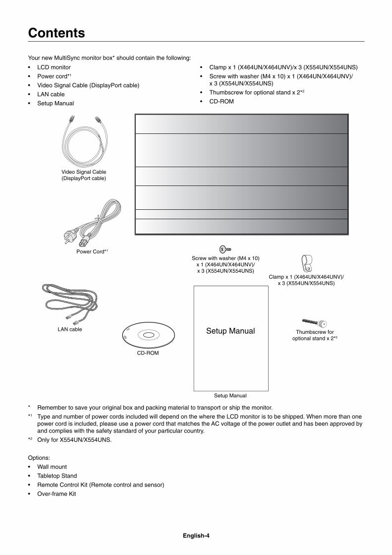
Your new MultiSync monitor box* should contain the following:
• LCD monitor
• Power cord*1
• Video Signal Cable (DisplayPort cable)
• LAN cable
• Setup Manual
• Clamp x 1 (X464UN/X464UNV)/x 3 (X554UN/X554UNS)
• Screw with washer (M4 x 10) x 1 (X464UN/X464UNV)/x 3 (X554UN/X554UNS)
• Thumbscrew for optional stand x 2*2
• CD-ROM
Power Cord*1
Setup Manual
Clamp x 1 (X464UN/X464UNV)/x 3 (X554UN/X554UNS)
CD-ROM
Screw with washer (M4 x 10) x 1 (X464UN/X464UNV)/ x 3 (X554UN/X554UNS)
Setup Manual
Video Signal Cable (DisplayPort cable)
Thumbscrew for optional stand x 2*2
LAN cable
* Remember to save your original box and packing material to transport or ship the monitor.
*1 Type and number of power cords included will depend on the where the LCD monitor is to be shipped. When more than one power cord is included, please use a power cord that matches the AC voltage of the power outlet and has been approved by and complies with the safety standard of your particular country.
*2 Only for X554UN/X554UNS.
Options:
• Wall mount
• Tabletop Stand
• Remote Control Kit (Remote control and sensor)
• Over-frame Kit
English-5
Eng
lish
This device cannot be used or installed without the Tabletop Stand or other mounting accessory for support. For proper installation it is strongly recommended to use a trained, NEC authorized service person. Failure to follow NEC standard mounting procedures could result in damage to the equipment or injury to the user or installer. Product warranty does not cover damage caused by improper installation. Failure to follow these recommendations could result in voiding the warranty.
MountingDO NOT mount the monitor yourself. Please ask dealer. For proper installation it is strongly recommended to use a trained, qualifi ed technician. Please inspect the location where the unit is to be mounted. Mounting on wall or ceiling is the customer’s responsibility. Not all walls or ceilings are capable of supporting the weight of the unit. Product warranty does not cover damage caused by improper installation, remodelling, or natural disasters. Failure to comply with these recommendations could result in voiding the warranty.
DO NOT block ventilated openings with mounting accessories or other accessories.
For NEC Qualifi ed Personnel:To ensure safe installation, use two or more brackets to mount the unit. Mount the unit to at least two points on the installation location.
Please note the following when mounting on wall or ceiling• When using mounting accessories other than those that
are NEC approved, they must comply with the VESA-compatible (FDMlv1) mounting method.
• NEC recommends mounting interfaces that comply with UL1678 standard in North America.
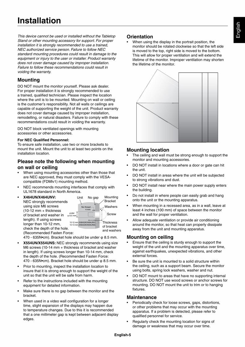
• X464UN/X464UNV: NEC strongly recommends using size M6 screws (10-12 mm + thickness of bracket and washer in length). If using screws longer than 10-12 mm, check the depth of the hole. (Recommended Fasten Force: 470 - 635N•cm). Bracket hole should be under � 8.5 mm.
• X554UN/X554UNS: NEC strongly recommends using size M6 screws (10-14 mm + thickness of bracket and washer in length). If using screws longer than 10-14 mm, check the depth of the hole. (Recommended Fasten Force: 470 - 635N•cm). Bracket hole should be under � 8.5 mm.
• Prior to mounting, inspect the installation location to insure that it is strong enough to support the weight of the unit so that the unit will be safe from harm.
• Refer to the instructions included with the mounting equipment for detailed information.
• Make sure there is no gap between the monitor and the bracket.
• When used in a video wall confi guration for a longer time, slight expansion of the displays may happen due to temperature changes. Due to this it is recommended that a one millimeter gap is kept between adjacent display edges.
Installation
Orientation • When using the display in the portrait position, the
monitor should be rotated clockwise so that the left side is moved to the top, right side is moved to the bottom. This will allow for proper ventilation and will extend the lifetime of the monitor. Improper ventilation may shorten the lifetime of the monitor.
Mounting location • The ceiling and wall must be strong enough to support the
monitor and mounting accessories.
• DO NOT install in locations where a door or gate can hit the unit.
• DO NOT install in areas where the unit will be subjected to strong vibrations and dust.
• DO NOT install near where the main power supply enters the building.
• Do not install in where people can easily grab and hang onto the unit or the mounting apparatus.
• When mounting in a recessed area, as in a wall, leave at least 4 inches (100 mm) of space between the monitor and the wall for proper ventilation.
• Allow adequate ventilation or provide air conditioning around the monitor, so that heat can properly dissipate away from the unit and mounting apparatus.
Mounting on ceiling • Ensure that the ceiling is sturdy enough to support the
weight of the unit and the mounting apparatus over time, against earthquakes, unexpected vibrations, and other external forces.
• Be sure the unit is mounted to a solid structure within the ceiling, such as a support beam. Secure the monitor using bolts, spring lock washers, washer and nut.
• DO NOT mount to areas that have no supporting internal structure. DO NOT use wood screws or anchor screws for mounting. DO NOT mount the unit to trim or to hanging fi xtures.
Maintenance • Periodically check for loose screws, gaps, distortions,
or other problems that may occur with the mounting apparatus. If a problem is detected, please refer to qualifi ed personnel for service.
• Regularly check the mounting location for signs of damage or weakness that may occur over time.
Screw
Unit
10-12 mm (X464UN/X464UNV)10-14 mm (X554UN/X554UNS)
Thickness of bracket and washers
under � 8.5 mm
No gap
Washers
MountingBracket
No thread4 mm
English-6
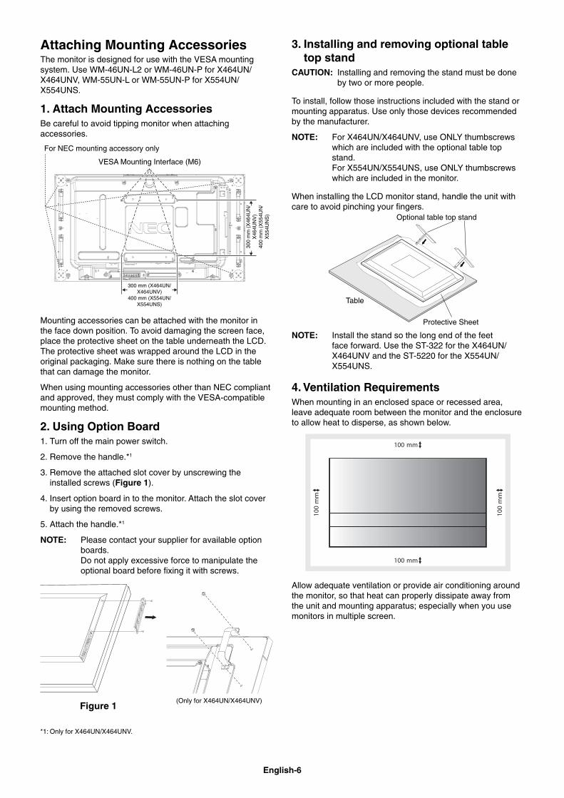
Attaching Mounting AccessoriesThe monitor is designed for use with the VESA mounting system. Use WM-46UN-L2 or WM-46UN-P for X464UN/X464UNV, WM-55UN-L or WM-55UN-P for X554UN/X554UNS.
1. Attach Mounting AccessoriesBe careful to avoid tipping monitor when attaching accessories.
VESA Mounting Interface (M6)
300 mm (X464UN/X464UNV)
400 mm (X554UN/X554UNS)
300
mm
(X
464U
N/
X46
4UN
V)
400
mm
(X
554U
N/
X55
4UN
S)
For NEC mounting accessory only
Mounting accessories can be attached with the monitor in the face down position. To avoid damaging the screen face, place the protective sheet on the table underneath the LCD. The protective sheet was wrapped around the LCD in the original packaging. Make sure there is nothing on the table that can damage the monitor.
When using mounting accessories other than NEC compliant and approved, they must comply with the VESA-compatible mounting method.
2. Using Option Board1. Turn off the main power switch.
2. Remove the handle.*1
3. Remove the attached slot cover by unscrewing the installed screws (Figure 1).
4. Insert option board in to the monitor. Attach the slot cover by using the removed screws.
5. Attach the handle.*1
NOTE: Please contact your supplier for available option boards.Do not apply excessive force to manipulate the optional board before fi xing it with screws.
Figure 1(Only for X464UN/X464UNV)
*1: Only for X464UN/X464UNV.
3. Installing and removing optional table top stand
CAUTION: Installing and removing the stand must be done by two or more people.
To install, follow those instructions included with the stand or mounting apparatus. Use only those devices recommended by the manufacturer.
NOTE: For X464UN/X464UNV, use ONLY thumbscrews which are included with the optional table top stand. For X554UN/X554UNS, use ONLY thumbscrews which are included in the monitor.
When installing the LCD monitor stand, handle the unit with care to avoid pinching your fi ngers.
Optional table top stand
Table
Protective Sheet
NOTE: Install the stand so the long end of the feet face forward. Use the ST-322 for the X464UN/X464UNV and the ST-5220 for the X554UN/X554UNS.
4. Ventilation Requirements When mounting in an enclosed space or recessed area, leave adequate room between the monitor and the enclosure to allow heat to disperse, as shown below.
Allow adequate ventilation or provide air conditioning around the monitor, so that heat can properly dissipate away from the unit and mounting apparatus; especially when you use monitors in multiple screen.
English-7
Eng
lish
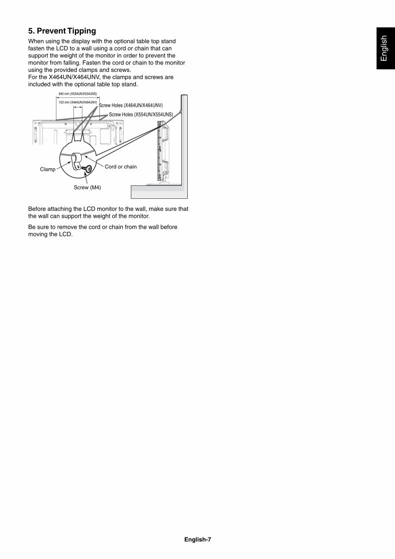
5. Prevent TippingWhen using the display with the optional table top stand fasten the LCD to a wall using a cord or chain that can support the weight of the monitor in order to prevent the monitor from falling. Fasten the cord or chain to the monitor using the provided clamps and screws.For the X464UN/X464UNV, the clamps and screws are included with the optional table top stand.
Screw (M4)
Cord or chainClamp
100 mm (X464UN/X464UNV)Screw Holes (X464UN/X464UNV)Screw Holes (X464UN/X464UNV)
Screw Holes (X554UN/X554UNS)Screw Holes (X554UN/X554UNS)
640 mm (X554UN/X554UNS)
Before attaching the LCD monitor to the wall, make sure that the wall can support the weight of the monitor.
Be sure to remove the cord or chain from the wall before moving the LCD.
English-8
Parts Name and Functions
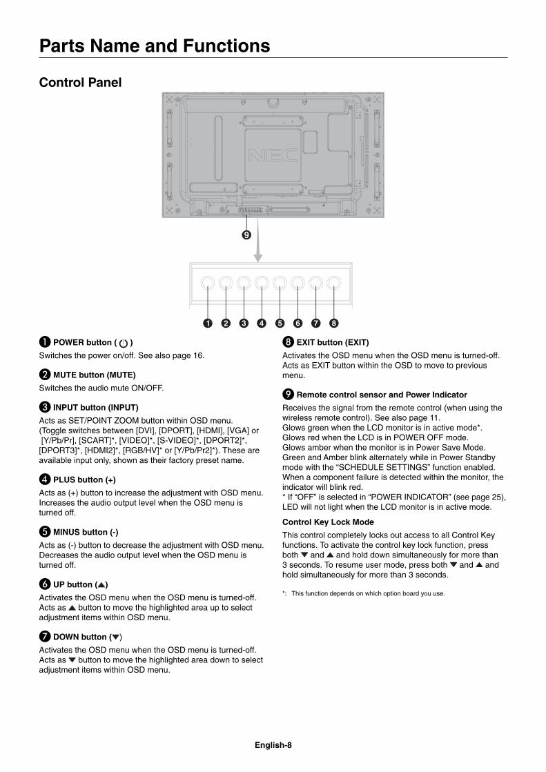
Control Panel
� POWER button ( )
Switches the power on/off. See also page 16.
� MUTE button (MUTE)
Switches the audio mute ON/OFF.
� INPUT button (INPUT)
Acts as SET/POINT ZOOM button within OSD menu. (Toggle switches between [DVI], [DPORT], [HDMI], [VGA] or [Y/Pb/Pr], [SCART]*, [VIDEO]*, [S-VIDEO]*, [DPORT2]*, [DPORT3]*, [HDMI2]*, [RGB/HV]* or [Y/Pb/Pr2]*). These are available input only, shown as their factory preset name.
� PLUS button (+)
Acts as (+) button to increase the adjustment with OSD menu.Increases the audio output level when the OSD menu is turned off.
� MINUS button (-)
Acts as (-) button to decrease the adjustment with OSD menu. Decreases the audio output level when the OSD menu is turned off.
� UP button ( )
Activates the OSD menu when the OSD menu is turned-off.Acts as button to move the highlighted area up to select adjustment items within OSD menu.
� DOWN button ( )
Activates the OSD menu when the OSD menu is turned-off.Acts as button to move the highlighted area down to select adjustment items within OSD menu.
EXIT button (EXIT)
Activates the OSD menu when the OSD menu is turned-off.Acts as EXIT button within the OSD to move to previous menu.
Remote control sensor and Power Indicator
Receives the signal from the remote control (when using the wireless remote control). See also page 11.Glows green when the LCD monitor is in active mode*. Glows red when the LCD is in POWER OFF mode. Glows amber when the monitor is in Power Save Mode. Green and Amber blink alternately while in Power Standby mode with the “SCHEDULE SETTINGS” function enabled. When a component failure is detected within the monitor, the indicator will blink red.* If “OFF” is selected in “POWER INDICATOR” (see page 25), LED will not light when the LCD monitor is in active mode.
Control Key Lock Mode
This control completely locks out access to all Control Key functions. To activate the control key lock function, press both and and hold down simultaneously for more than 3 seconds. To resume user mode, press both and and hold simultaneously for more than 3 seconds.
*: This function depends on which option board you use.
English-9
Eng
lish
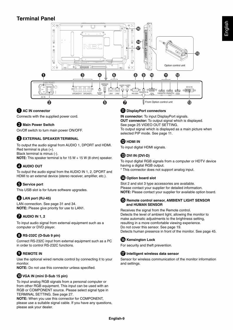
Terminal Panel
Option control unit
From Option control unit
� AC IN connector
Connects with the supplied power cord.
� Main Power Switch
On/Off switch to turn main power ON/OFF.
� EXTERNAL SPEAKER TERMINAL
To output the audio signal from AUDIO 1, DPORT and HDMI. Red terminal is plus (+). Black terminal is minus (-).NOTE: This speaker terminal is for 15 W + 15 W (8 ohm) speaker.
� AUDIO OUT
To output the audio signal from the AUDIO IN 1, 2, DPORT and HDMI to an external device (stereo receiver, amplifi er, etc.).
� Service port
This USB slot is for future software upgrades.
� LAN port (RJ-45)
LAN connection. See page 31 and 34.NOTE: Please give priority for use to LAN1.
� AUDIO IN 1, 2
To input audio signal from external equipment such as a computer or DVD player.
� RS-232C (D-Sub 9 pin)
Connect RS-232C input from external equipment such as a PC in order to control RS-232C functions.
REMOTE IN
Use the optional wired remote control by connecting it to your monitor.NOTE: Do not use this connector unless specifi ed.
� VGA IN (mini D-Sub 15 pin)
To input analog RGB signals from a personal computer or from other RGB equipment. This input can be used with an RGB or COMPONENT source. Please select signal type in TERMINAL SETTING. See page 27.NOTE: When you use this connector for COMPONENT, please use a suitable signal cable. If you have any questions, please ask your dealer.
DisplayPort connectors
IN connector: To input DisplayPort signals.OUT connector: To output signal which is displayed. See page 25 VIDEO OUT SETTING.To output signal which is displayed as a main picture when selected PIP mode. See page 11.
� HDMI IN
To input digital HDMI signals.
� DVI IN (DVI-D)
To input digital RGB signals from a computer or HDTV device having a digital RGB output.* This connector does not support analog input.
� Option board slot
Slot 2 and slot 3 type accessories are available. Please contact your supplier for detailed information.NOTE: Please contact your supplier for available option board.
� Remote control sensor, AMBIENT LIGHT SENSOR and HUMAN SENSOR
Receives the signal from the Remote control.Detects the level of ambient light, allowing the monitor to make automatic adjustments to the brightness setting, resulting in a more comfortable viewing experience. Do not cover this sensor. See page 19.Detects human presence in front of the monitor. See page 45.
� Kensington Lock
For security and theft prevention.
� Intelligent wireless data sensor
Sensor for wireless communication of the monitor information and settings.
English-10
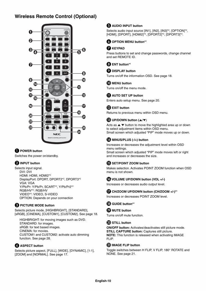
Wireless Remote Control (Optional)
� POWER button
Switches the power on/standby.
� INPUT button
Selects input signal. DVI: DVI HDMI: HDMI, HDMI2*2
DisplayPort: DPORT, DPORT2*2, DPORT3*2
VGA: VGA Y/Pb/Pr: Y/Pb/Pr, SCART*2, Y/Pb/Pr2*2
RGB/HV*2: RGB/HV VIDEO*2: VIDEO, S-VIDEO OPTION: Depends on your connection
� PICTURE MODE button
Selects picture mode, [HIGHBRIGHT], [STANDARD], [sRGB], [CINEMA], [CUSTOM1], [CUSTOM2]. See page 18.
HIGHBRIGHT: for moving images such as DVD. STANDARD: for images. sRGB: for text based images. CINEMA: for movies. CUSTOM1 and CUSTOM2: activate auto dimming function. See page 28.
� ASPECT button
Selects picture aspect, [FULL], [WIDE], [DYNAMIC], [1:1], [ZOOM] and [NORMAL]. See page 17.
� AUDIO INPUT button
Selects audio input source [IN1], [IN2], [IN3]*2, [OPTION]*2, [HDMI], [DPORT], [HDMI2]*2, [DPORT2]*2, [DPORT3]*2.
� OPTION MENU button*1
� KEYPAD
Press buttons to set and change passwords, change channel and set REMOTE ID.
ENT button*1
DISPLAY button
Turns on/off the information OSD. See page 18.
� MENU button
Turns on/off the menu mode.
AUTO SET UP button
Enters auto setup menu. See page 20.
� EXIT button
Returns to previous menu within OSD menu.
� UP/DOWN button ( / )
Acts as button to move the highlighted area up or down to select adjustment items within OSD menu.Small screen which adjusted “PIP” mode moves up or down.
� MINUS/PLUS (-/+) button
Increases or decreases the adjustment level within OSD menu settings.Small screen which adjusted “PIP” mode moves left or right and increases or decreases the size.
� SET/POINT ZOOM button
Makes selection. Activates POINT ZOOM function when OSD menu is not shown.
� VOLUME UP/DOWN button (VOL +/-)
Increases or decreases audio output level.
� CH/ZOOM UP/DOWN button (CH/ZOOM +/-)*1
Increases or decreases POINT ZOOM level.
� GUIDE button*1
� MUTE button
Turns on/off mute function.
� STILL button
ON/OFF button: Activates/deactivates still picture mode.STILL CAPTURE button: Captures still picture.NOTE: This function is released when activating IMAGE FLIP.
IMAGE FLIP button
Toggle switches between H FLIP, V FLIP, 180° ROTATE and NONE. See page 21.
English-11
Eng
lish
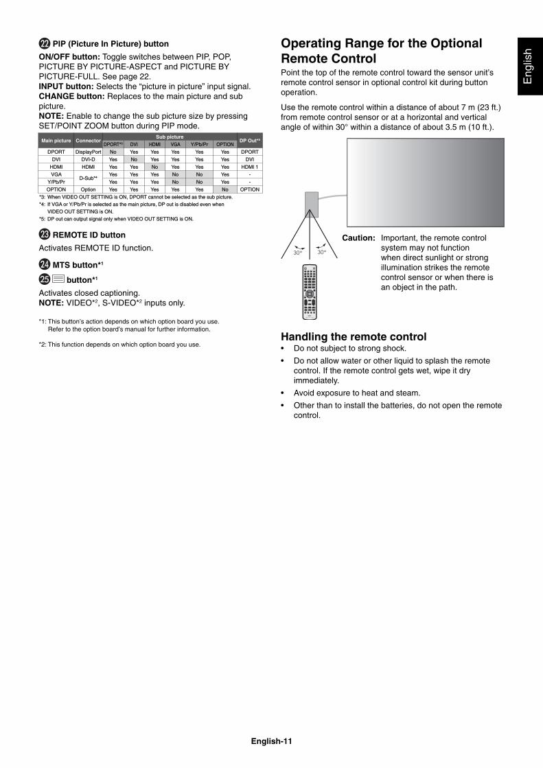
Operating Range for the Optional Remote ControlPoint the top of the remote control toward the sensor unit’s remote control sensor in optional control kit during button operation.
Use the remote control within a distance of about 7 m (23 ft.) from remote control sensor or at a horizontal and vertical angle of within 30° within a distance of about 3.5 m (10 ft.).
Caution: Important, the remote control system may not function when direct sunlight or strong illumination strikes the remote control sensor or when there is an object in the path.
Handling the remote control• Do not subject to strong shock.
• Do not allow water or other liquid to splash the remote control. If the remote control gets wet, wipe it dry immediately.
• Avoid exposure to heat and steam.
• Other than to install the batteries, do not open the remote control.
PIP (Picture In Picture) button
ON/OFF button: Toggle switches between PIP, POP, PICTURE BY PICTURE-ASPECT and PICTURE BY PICTURE-FULL. See page 22.INPUT button: Selects the “picture in picture” input signal.CHANGE button: Replaces to the main picture and sub picture.NOTE: Enable to change the sub picture size by pressing SET/POINT ZOOM button during PIP mode.
Main picture ConnectorSub picture
DP Out*5
DPORT*DPORT*3 DVIDVI HDMIHDMI VGAVGA Y/Pb/PrY/Pb/Pr OPTIONOPTION
DPORTDPORT DisplayPortDisplayPort NoNo YesYes YesYes YesYes YesYes YesYes DPORTDPORT
DVIDVI DVI-DDVI-D YesYes NoNo YesYes YesYes YesYes YesYes DVIDVI
HDMIHDMI HDMIHDMI YesYes YesYes NoNo YesYes YesYes YesYes HDMI 1HDMI 1
VGAVGAD-Sub*D-Sub*4
YesYes YesYes YesYes NoNo NoNo YesYes -
Y/Pb/PrY/Pb/Pr YesYes YesYes YesYes NoNo NoNo YesYes -
OPTIONOPTION OptionOption YesYes YesYes YesYes YesYes YesYes NoNo OPTIONOPTION
*3: When VIDEO OUT SETTING is ON, DPORT cannot be selected as the sub picture.*3: When VIDEO OUT SETTING is ON, DPORT cannot be selected as the sub picture.
*4: If VGA or Y/Pb/Pr is selected as the main picture, DP out is disabled even when *4: If VGA or Y/Pb/Pr is selected as the main picture, DP out is disabled even when
VIDEO OUT SETTING is ON. VIDEO OUT SETTING is ON.
*5: DP out can output signal only when VIDEO OUT SETTING is ON.*5: DP out can output signal only when VIDEO OUT SETTING is ON.
REMOTE ID button
Activates REMOTE ID function.
MTS button*1
button*1
Activates closed captioning.NOTE: VIDEO*2, S-VIDEO*2 inputs only.
*1: This button’s action depends on which option board you use. Refer to the option board’s manual for further information.
*2: This function depends on which option board you use.
English-12
1. Determine the installation locationCAUTION: Installing your LCD monitor must be done by a
qualifi ed technician. Contact your dealer for more information.
CAUTION: MOVING OR INSTALLING THE LCD MONITOR MUST BE DONE BY TWO OR MORE PEOPLE. Failure to follow this caution may result in injury if the LCD monitor falls.
CAUTION: Do not mount or operate the monitor upside down, face up or face down.
CAUTION: This LCD has a temperature sensor and cooling fan, including a fan for the option board.If the LCD becomes too hot, the cooling fan will turn on automatically. The option board’s fan is active although the temperature is lower than normal operating temperature for cooling the option board. If the LCD becomes overheated while the cooling fan is running, a “Caution” warning will appear. If the “Caution” warning appears, discontinue use and allow the unit to cool. Using the cooling fan will reduce the likelihood of early circuit failure and may help reduce image degradation and “Image Persistance”.If the LCD is used in an enclosed area or if the LCD panel is covered with a protective screen, please check the inside temperature of the monitor by using the “HEAT STATUS” control in the OSD (see page 25). If the temperature is higher than the normal operating temperature, please turn the cooling fan to ON within the FAN CONTROL menu within the OSD (see page 25).
IMPORTANT: Lay the protective sheet, which was wrapped around the LCD monitor when it was packaged, beneath the LCD monitor so as not to scratch the panel.
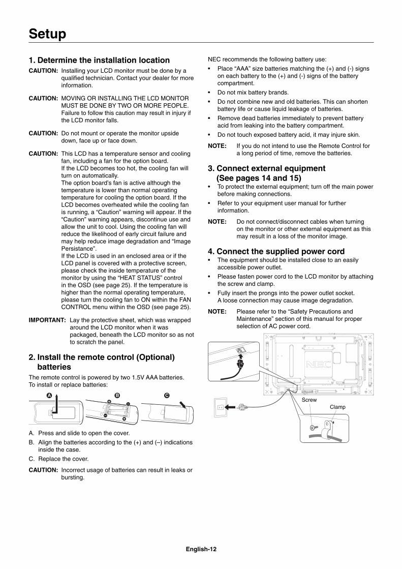
2. Install the remote control (Optional)batteries
The remote control is powered by two 1.5V AAA batteries. To install or replace batteries:
A. Press and slide to open the cover.
B. Align the batteries according to the (+) and (–) indications inside the case.
C. Replace the cover.
CAUTION: Incorrect usage of batteries can result in leaks or bursting.
NEC recommends the following battery use:
• Place “AAA” size batteries matching the (+) and (-) signs on each battery to the (+) and (-) signs of the battery compartment.
• Do not mix battery brands.
• Do not combine new and old batteries. This can shorten battery life or cause liquid leakage of batteries.
• Remove dead batteries immediately to prevent battery acid from leaking into the battery compartment.
• Do not touch exposed battery acid, it may injure skin.
NOTE: If you do not intend to use the Remote Control for a long period of time, remove the batteries.
3. Connect external equipment (See pages 14 and 15)• To protect the external equipment; turn off the main power
before making connections.
• Refer to your equipment user manual for further information.
NOTE: Do not connect/disconnect cables when turning on the monitor or other external equipment as this may result in a loss of the monitor image.
4. Connect the supplied power cord• The equipment should be installed close to an easily
accessible power outlet.
• Please fasten power cord to the LCD monitor by attaching the screw and clamp.
• Fully insert the prongs into the power outlet socket. A loose connection may cause image degradation.
NOTE: Please refer to the “Safety Precautions and Maintenance” section of this manual for proper selection of AC power cord.
ScrewClamp
Setup
English-13
Eng
lish
5. Switch on the power of all the attached external equipment
When connected with a computer, switch on the power of the computer fi rst.
6. Operate the attached external equipmentDisplay the signal from the desired input source.
7. Adjust the soundMake volume adjustments when required.
8. Adjust the screen (See pages 20 and 21)Make adjustments of the screen display position when necessary.
9. Adjust the image (See page 20)Make adjustments such as backlight or contrast when required.
10. Recommended AdjustmentsTo reduce the risk of the “Image Persistence”, please adjust the following items based on the application being used: “SCREEN SAVER”, “SIDE BORDER COLOR” (See page 25) “DATE & TIME”, “SCHEDULE SETTINGS” (See page 22). It is recommended that the “FAN CONTROL” setting (See page 25) be turned to ON also.
English-14
Connections
NOTE: Do not connect/disconnect cables when turning on the monitor or other external equipment as this may result in a loss of the monitor image.
NOTE: Use an audio cable without a built-in resistor. Using an audio cable with a built-in resistor turns down the sound.
Before making connections:* First turn off the power of all the attached equipment and make connections.
* Refer to the user manual included with each separate piece of equipment.
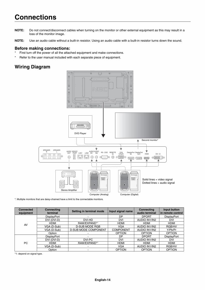
Wiring Diagram
Solid lines = video signal Dotted lines = audio signal
Stereo Amplifi er
Second monitor*
Computer (Analog) Computer (Digital)
DVD Player
*: Multiple monitors that are daisy-chained have a limit to the connectable monitors.
Connected equipment
Connectingterminal
Setting in terminal mode Input signal nameConnecting
audio terminalInput button
in remote control
AV
DisplayPort - DP DPORT DisplayPortDVI (DVI-D) DVI-HD DVI AUDIO IN1/IN2 DVI
HDMI RAW/EXPAND*1 HDMI HDMI HDMIVGA (D-Sub) D-SUB MODE RGB VGA AUDIO IN1/IN2 RGB/HVVGA (D-Sub) D-SUB MODE COMPONENT COMPONENT AUDIO IN1/IN2 Y/Pb/Pr
Option - OPTION OPTION OPTION
PC
DisplayPort - DP DPORT DisplayPortDVI (DVI-D) DVI-PC DVI AUDIO IN1/IN2 DVI
HDMI RAW/EXPAND*1 HDMI HDMI HDMIVGA (D-Sub) - VGA AUDIO IN1/IN2 RGB/HV
Option - OPTION OPTION OPTION*1: depend on signal type.
English-15
Eng
lish
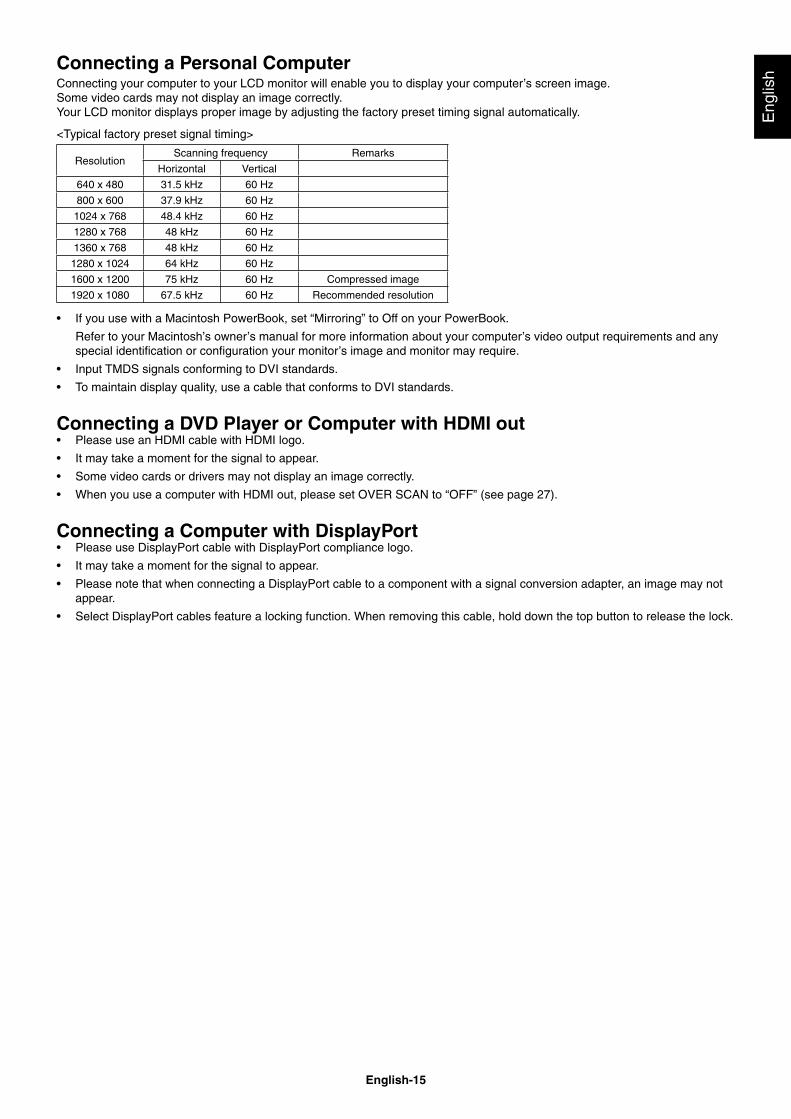
Connecting a Personal ComputerConnecting your computer to your LCD monitor will enable you to display your computer’s screen image.Some video cards may not display an image correctly.Your LCD monitor displays proper image by adjusting the factory preset timing signal automatically.
<Typical factory preset signal timing>
ResolutionScanning frequency Remarks
Horizontal Vertical
640 x 480 31.5 kHz 60 Hz
800 x 600 37.9 kHz 60 Hz
1024 x 768 48.4 kHz 60 Hz
1280 x 768 48 kHz 60 Hz
1360 x 768 48 kHz 60 Hz
1280 x 1024 64 kHz 60 Hz
1600 x 1200 75 kHz 60 Hz Compressed image
1920 x 1080 67.5 kHz 60 Hz Recommended resolution
• If you use with a Macintosh PowerBook, set “Mirroring” to Off on your PowerBook.
Refer to your Macintosh’s owner’s manual for more information about your computer’s video output requirements and any special identifi cation or confi guration your monitor’s image and monitor may require.
• Input TMDS signals conforming to DVI standards.
• To maintain display quality, use a cable that conforms to DVI standards.
Connecting a DVD Player or Computer with HDMI out• Please use an HDMI cable with HDMI logo.
• It may take a moment for the signal to appear.
• Some video cards or drivers may not display an image correctly.
• When you use a computer with HDMI out, please set OVER SCAN to “OFF” (see page 27).
Connecting a Computer with DisplayPort• Please use DisplayPort cable with DisplayPort compliance logo.
• It may take a moment for the signal to appear.
• Please note that when connecting a DisplayPort cable to a component with a signal conversion adapter, an image may not appear.
• Select DisplayPort cables feature a locking function. When removing this cable, hold down the top button to release the lock.
English-16
Basic Operation
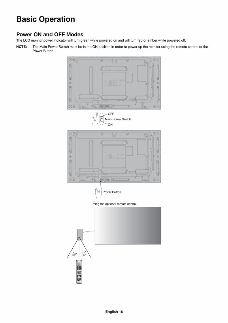
Power ON and OFF ModesThe LCD monitor power indicator will turn green while powered on and will turn red or amber while powered off.
NOTE: The Main Power Switch must be in the ON position in order to power up the monitor using the remote control or the Power Button.
Main Power Switch
ON
OFF
Power Button
Using the optional remote control
English-17
Eng
lish
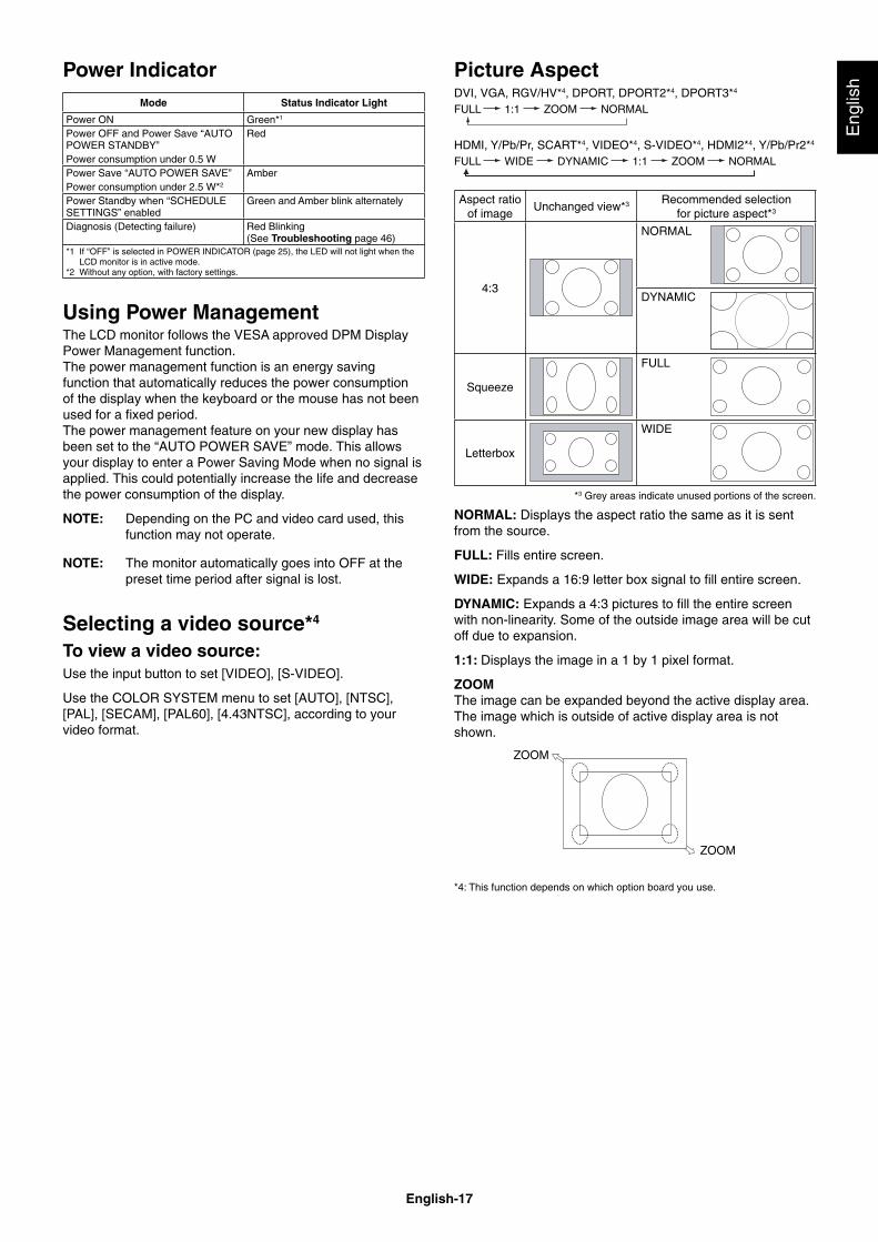
Picture AspectDVI, VGA, RGV/HV*4, DPORT, DPORT2*4, DPORT3*4
FULL 1:1 ZOOM NORMAL
HDMI, Y/Pb/Pr, SCART*4, VIDEO*4, S-VIDEO*4, HDMI2*4, Y/Pb/Pr2*4
FULL WIDE DYNAMIC 1:1 ZOOM NORMAL
Aspect ratioof image
Unchanged view*3 Recommended selectionfor picture aspect*3
4:3
NORMAL
DYNAMIC
Squeeze
FULL
Letterbox
WIDE
*3 Grey areas indicate unused portions of the screen.
NORMAL: Displays the aspect ratio the same as it is sent from the source.
FULL: Fills entire screen.
WIDE: Expands a 16:9 letter box signal to fi ll entire screen.
DYNAMIC: Expands a 4:3 pictures to fi ll the entire screen with non-linearity. Some of the outside image area will be cut off due to expansion.
1:1: Displays the image in a 1 by 1 pixel format.
ZOOMThe image can be expanded beyond the active display area. The image which is outside of active display area is not shown.
ZOOM
ZOOM
*4: This function depends on which option board you use.
Power IndicatorMode Status Indicator Light
Power ON Green*1
Power OFF and Power Save “AUTO POWER STANDBY”Power consumption under 0.5 W
Red
Power Save “AUTO POWER SAVE”Power consumption under 2.5 W*2
Amber
Power Standby when “SCHEDULE SETTINGS” enabled
Green and Amber blink alternately
Diagnosis (Detecting failure) Red Blinking(See Troubleshooting page 46)
*1 If “OFF” is selected in POWER INDICATOR (page 25), the LED will not light when the LCD monitor is in active mode.*2 Without any option, with factory settings.
Using Power ManagementThe LCD monitor follows the VESA approved DPM Display Power Management function.The power management function is an energy saving function that automatically reduces the power consumption of the display when the keyboard or the mouse has not been used for a fi xed period.The power management feature on your new display has been set to the “AUTO POWER SAVE” mode. This allows your display to enter a Power Saving Mode when no signal is applied. This could potentially increase the life and decrease the power consumption of the display.
NOTE: Depending on the PC and video card used, this function may not operate.
NOTE: The monitor automatically goes into OFF at the preset time period after signal is lost.
Selecting a video source*4
To view a video source:Use the input button to set [VIDEO], [S-VIDEO].
Use the COLOR SYSTEM menu to set [AUTO], [NTSC], [PAL], [SECAM], [PAL60], [4.43NTSC], according to your video format.
English-18
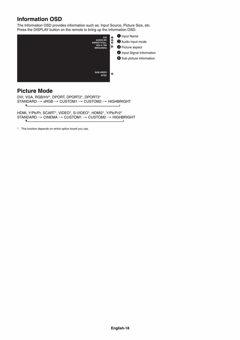
Information OSDThe Information OSD provides information such as: Input Source, Picture Size, etc. Press the DISPLAY button on the remote to bring up the Information OSD.
� Input Name
� Audio input mode
� Picture aspect
� Input Signal Information
� Sub picture information
Picture ModeDVI, VGA, RGB/HV*, DPORT, DPORT2*, DPORT3* STANDARD sRGB CUSTOM1 CUSTOM2 HIGHBRIGHT
HDMI, Y/Pb/Pr, SCART*, VIDEO*, S-VIDEO*, HDMI2*, Y/Pb/Pr2*STANDARD CINEMA CUSTOM1 CUSTOM2 HIGHBRIGHT
*: This function depends on which option board you use.
English-19
Eng
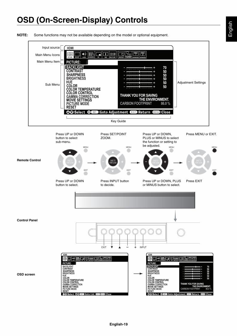
lishOSD (On-Screen-Display) Controls
NOTE: Some functions may not be available depending on the model or optional equipment.
PICTURE MODE
Goto AdjustmentSelect Return Close
705050505050
THANK YOU FOR SAVING THE ENVIRONMENT.CARBON FOOTPRINT 86.0 %
Input source
Main Menu Icons
Main Menu Item
Sub Menu
Key Guide
Adjustment Settings
Remote Control
Press UP or DOWN button to select sub-menu.
Press SET/POINT ZOOM.
Press UP or DOWN, PLUS or MINUS to select the function or setting to be adjusted.
Press MENU or EXIT.
Press UP or DOWN button to select.
Press INPUT button to decide.
Press UP or DOWN, PLUS or MINUS button to select.
Press EXIT
Control Panel
OSD screen
English-20
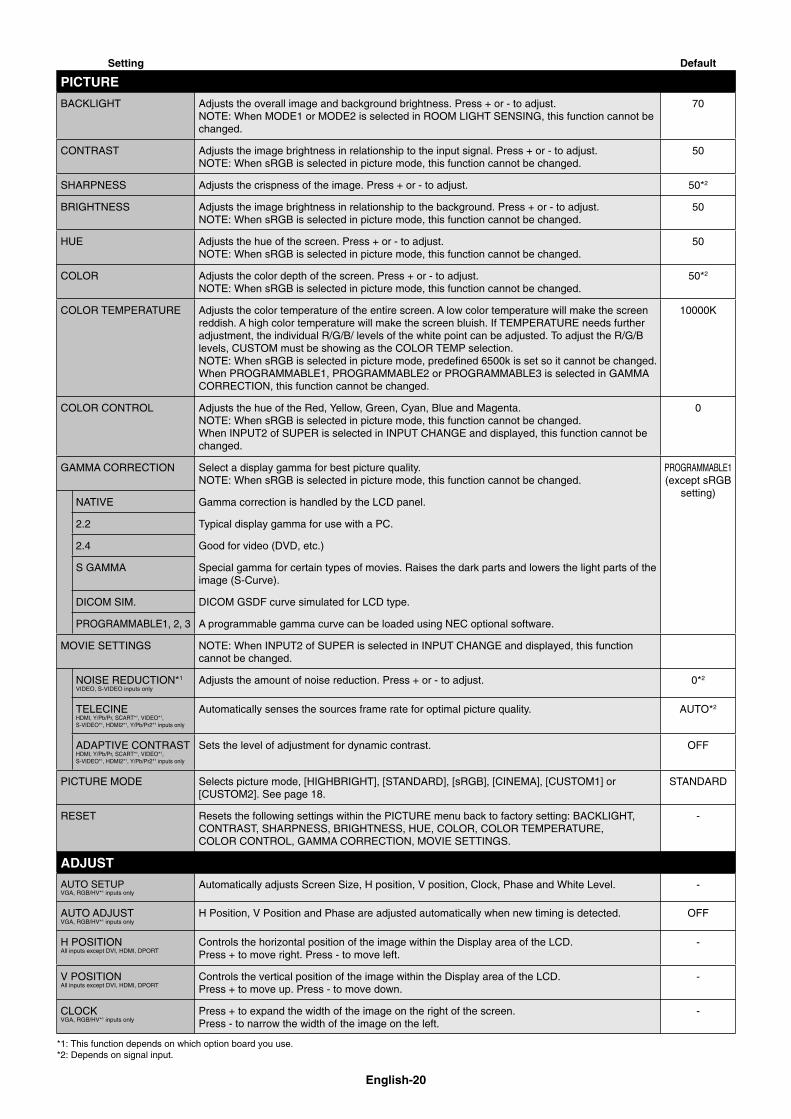
Setting Default
PICTURE
BACKLIGHT Adjusts the overall image and background brightness. Press + or - to adjust.NOTE: When MODE1 or MODE2 is selected in ROOM LIGHT SENSING, this function cannot be changed.
70
CONTRAST Adjusts the image brightness in relationship to the input signal. Press + or - to adjust.NOTE: When sRGB is selected in picture mode, this function cannot be changed.
50
SHARPNESS Adjusts the crispness of the image. Press + or - to adjust. 50*2
BRIGHTNESS Adjusts the image brightness in relationship to the background. Press + or - to adjust.NOTE: When sRGB is selected in picture mode, this function cannot be changed.
50
HUE Adjusts the hue of the screen. Press + or - to adjust.NOTE: When sRGB is selected in picture mode, this function cannot be changed.
50
COLOR Adjusts the color depth of the screen. Press + or - to adjust.NOTE: When sRGB is selected in picture mode, this function cannot be changed.
50*2
COLOR TEMPERATURE Adjusts the color temperature of the entire screen. A low color temperature will make the screen reddish. A high color temperature will make the screen bluish. If TEMPERATURE needs further adjustment, the individual R/G/B/ levels of the white point can be adjusted. To adjust the R/G/B levels, CUSTOM must be showing as the COLOR TEMP selection.NOTE: When sRGB is selected in picture mode, predefi ned 6500k is set so it cannot be changed.When PROGRAMMABLE1, PROGRAMMABLE2 or PROGRAMMABLE3 is selected in GAMMA CORRECTION, this function cannot be changed.
10000K
COLOR CONTROL Adjusts the hue of the Red, Yellow, Green, Cyan, Blue and Magenta.NOTE: When sRGB is selected in picture mode, this function cannot be changed.When INPUT2 of SUPER is selected in INPUT CHANGE and displayed, this function cannot be changed.
0
GAMMA CORRECTION Select a display gamma for best picture quality.NOTE: When sRGB is selected in picture mode, this function cannot be changed.
PROGRAMMABLE1(except sRGB
setting)NATIVE Gamma correction is handled by the LCD panel.
2.2 Typical display gamma for use with a PC.
2.4 Good for video (DVD, etc.)
S GAMMA Special gamma for certain types of movies. Raises the dark parts and lowers the light parts of the image (S-Curve).
DICOM SIM. DICOM GSDF curve simulated for LCD type.
PROGRAMMABLE1, 2, 3 A programmable gamma curve can be loaded using NEC optional software.
MOVIE SETTINGS NOTE: When INPUT2 of SUPER is selected in INPUT CHANGE and displayed, this function cannot be changed.
NOISE REDUCTION*1
VIDEO, S-VIDEO inputs onlyAdjusts the amount of noise reduction. Press + or - to adjust. 0*2
TELECINEHDMI, Y/Pb/Pr, SCART*1, VIDEO*1, S-VIDEO*1, HDMI2*1, Y/Pb/Pr2*1 inputs only
Automatically senses the sources frame rate for optimal picture quality. AUTO*2
ADAPTIVE CONTRASTHDMI, Y/Pb/Pr, SCART*1, VIDEO*1, S-VIDEO*1, HDMI2*1, Y/Pb/Pr2*1 inputs only
Sets the level of adjustment for dynamic contrast. OFF
PICTURE MODE Selects picture mode, [HIGHBRIGHT], [STANDARD], [sRGB], [CINEMA], [CUSTOM1] or [CUSTOM2]. See page 18.
STANDARD
RESET Resets the following settings within the PICTURE menu back to factory setting: BACKLIGHT, CONTRAST, SHARPNESS, BRIGHTNESS, HUE, COLOR, COLOR TEMPERATURE, COLOR CONTROL, GAMMA CORRECTION, MOVIE SETTINGS.
-
ADJUST
AUTO SETUPVGA, RGB/HV*1 inputs only
Automatically adjusts Screen Size, H position, V position, Clock, Phase and White Level. -
AUTO ADJUSTVGA, RGB/HV*1 inputs only
H Position, V Position and Phase are adjusted automatically when new timing is detected. OFF
H POSITIONAll inputs except DVI, HDMI, DPORT
Controls the horizontal position of the image within the Display area of the LCD.Press + to move right. Press - to move left.
-
V POSITIONAll inputs except DVI, HDMI, DPORT
Controls the vertical position of the image within the Display area of the LCD.Press + to move up. Press - to move down.
-
CLOCKVGA, RGB/HV*1 inputs only
Press + to expand the width of the image on the right of the screen.Press - to narrow the width of the image on the left.
-
*1: This function depends on which option board you use.*2: Depends on signal input.
English-21
Eng
lish
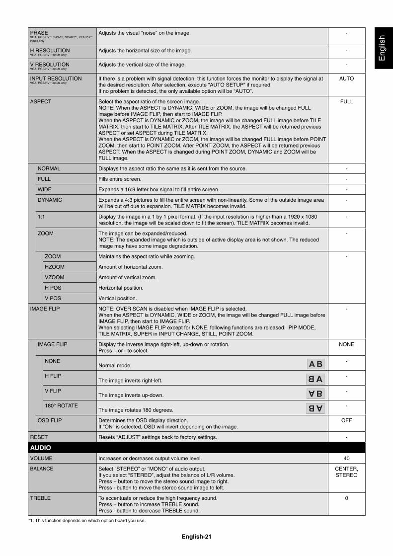
PHASEVGA, RGB/HV*1, Y/Pb/Pr, SCART*1, Y/Pb/Pr2*1 inputs only
Adjusts the visual “noise” on the image. -
H RESOLUTIONVGA, RGB/HV*1 inputs only
Adjusts the horizontal size of the image. -
V RESOLUTIONVGA, RGB/HV*1 inputs only
Adjusts the vertical size of the image. -
INPUT RESOLUTIONVGA, RGB/HV*1 inputs only
If there is a problem with signal detection, this function forces the monitor to display the signal at the desired resolution. After selection, execute “AUTO SETUP” if required.If no problem is detected, the only available option will be “AUTO”.
AUTO
ASPECT Select the aspect ratio of the screen image.NOTE: When the ASPECT is DYNAMIC, WIDE or ZOOM, the image will be changed FULL image before IMAGE FLIP, then start to IMAGE FLIP.When the ASPECT is DYNAMIC or ZOOM, the image will be changed FULL image before TILE MATRIX, then start to TILE MATRIX. After TILE MATRIX, the ASPECT will be returned previous ASPECT or set ASPECT during TILE MATRIX.When the ASPECT is DYNAMIC or ZOOM, the image will be changed FULL image before POINT ZOOM, then start to POINT ZOOM. After POINT ZOOM, the ASPECT will be returned previous ASPECT. When the ASPECT is changed during POINT ZOOM, DYNAMIC and ZOOM will be FULL image.
FULL
NORMAL Displays the aspect ratio the same as it is sent from the source. -
FULL Fills entire screen. -
WIDE Expands a 16:9 letter box signal to fi ll entire screen. -
DYNAMIC Expands a 4:3 pictures to fi ll the entire screen with non-linearity. Some of the outside image area will be cut off due to expansion. TILE MATRIX becomes invalid.
-
1:1 Display the image in a 1 by 1 pixel format. (If the input resolution is higher than a 1920 x 1080 resolution, the image will be scaled down to fi t the screen). TILE MATRIX becomes invalid.
-
ZOOM The image can be expanded/reduced.NOTE: The expanded image which is outside of active display area is not shown. The reduced image may have some image degradation.
-
ZOOM Maintains the aspect ratio while zooming. -
HZOOM Amount of horizontal zoom.
VZOOM Amount of vertical zoom.
H POS Horizontal position.
V POS Vertical position.
IMAGE FLIP NOTE: OVER SCAN is disabled when IMAGE FLIP is selected.When the ASPECT is DYNAMIC, WIDE or ZOOM, the image will be changed FULL image before IMAGE FLIP, then start to IMAGE FLIP.When selecting IMAGE FLIP except for NONE, following functions are released: PIP MODE, TILE MATRIX, SUPER in INPUT CHANGE, STILL, POINT ZOOM.
-
IMAGE FLIP Display the inverse image right-left, up-down or rotation.Press + or - to select.
NONE
NONENormal mode.
-
H FLIPThe image inverts right-left.
-
V FLIPThe image inverts up-down.
-
180° ROTATEThe image rotates 180 degrees.
-
OSD FLIP Determines the OSD display direction.If “ON” is selected, OSD will invert depending on the image.
OFF
RESET Resets “ADJUST” settings back to factory settings. -
AUDIO
VOLUME Increases or decreases output volume level. 40
BALANCE Select “STEREO” or “MONO” of audio output.If you select “STEREO”, adjust the balance of L/R volume.Press + button to move the stereo sound image to right.Press - button to move the stereo sound image to left.
CENTER, STEREO
TREBLE To accentuate or reduce the high frequency sound.Press + button to increase TREBLE sound.Press - button to decrease TREBLE sound.
0
*1: This function depends on which option board you use.
English-22
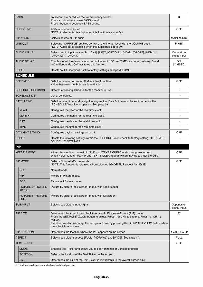
BASS To accentuate or reduce the low frequency sound.Press + button to increase BASS sound.Press - button to decrease BASS sound.
0
SURROUND Artifi cial surround sound.NOTE: Audio out is disabled when this function is set to ON.
OFF
PIP AUDIO Selects source of PIP audio. MAIN AUDIO
LINE OUT Selecting “VARIABLE” enables control of the line out level with the VOLUME button.NOTE: Audio out is disabled when this function is set to ON.
FIXED
AUDIO INPUT Selects audio input source [IN1], [IN2], [IN3]*1, [OPTION]*1, [HDMI], [DPORT], [HDMI2]*1, [DPORT2]*1, [DPORT3]*1.
Depend on signal input
AUDIO DELAY Enables to set the delay time to output the audio. DELAY TIME can be set between 0 and 100 milliseconds. “ON” activates this function.
ON, 37 MSEC.
RESET Resets “AUDIO” options back to factory settings except VOLUME. -
SCHEDULE
OFF TIMER Sets the monitor to power off after a length of time.A time between 1 to 24 hours is available.
OFF
SCHEDULE SETTINGS Creates a working schedule for the monitor to use. -
SCHEDULE LIST List of schedules. -
DATE & TIME Sets the date, time, and daylight saving region. Date & time must be set in order for the “SCHEDULE” function to operate. See page 29.
YEAR Confi gures the year for the real-time clock. -
MONTH Confi gures the month for the real-time clock. -
DAY Confi gures the day for the real-time clock. -
TIME Confi gures the time for the real-time clock. -
DAYLIGHT SAVING Confi gures daylight savings on or off. OFF
RESET Resets the following settings within the SCHEDULE menu back to factory setting: OFF TIMER, SCHEDULE SETTINGS.
-
PIP
KEEP PIP MODE Allows the monitor to remain in “PIP” and “TEXT TICKER” mode after powering off.When Power is returned, PIP and TEXT TICKER appear without having to enter the OSD.
OFF
PIP MODE Selects Picture-in-Picture mode.NOTE: This function is released when selecting IMAGE FLIP except for NONE.
OFF
OFF Normal mode.
PIP Picture in Picture mode.
POP Picture out Picture mode.
PICTURE BY PICTURE-ASPECT
Picture by picture (split screen) mode, with keep aspect.
PICTURE BY PICTURE-FULL
Picture by picture (split screen) mode, with full screen.
SUB INPUT Selects sub picture input signal. Depends on signal input
PIP SIZE Determines the size of the sub-picture used in Picture-in-Picture (PIP) mode. Press the SET/POINT ZOOM button to adjust. Press + or CH+ to expand. Press - or CH- to reduce.It is also possible to change the sub-picture size by pressing the SET/POINT ZOOM button when the sub-picture is shown.
37
PIP POSITION Determines the location where the PIP appears on the screen. X = 95, Y = 92
ASPECT Selects sub picture aspect, [FULL], [NORMAL] and [WIDE]. See page 17. FULL
TEXT TICKER OFF
MODE Enables Text Ticker and allows you to set Horizontal or Vertical direction.
POSITION Selects the location of the Text Ticker on the screen.
SIZE Determines the size of the Text Ticker in relationship to the overall screen size.
*1: This function depends on which option board you use.
English-23
Eng
lish
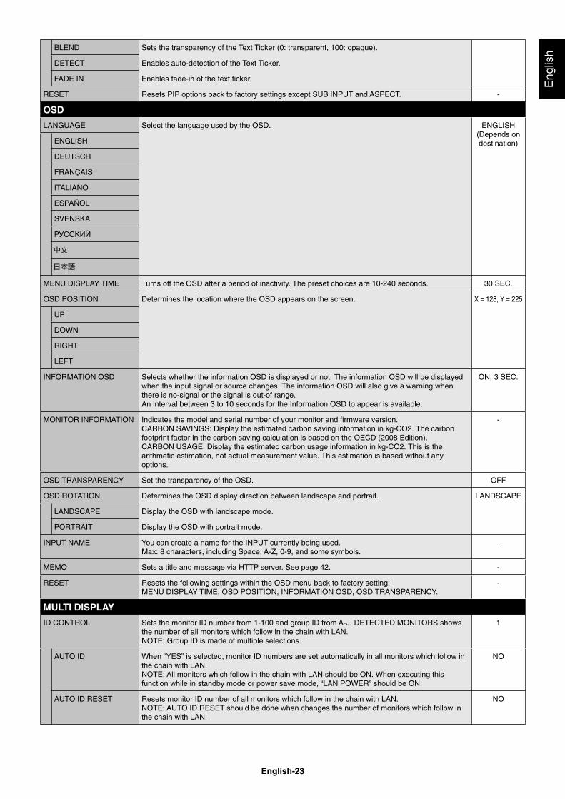
BLEND Sets the transparency of the Text Ticker (0: transparent, 100: opaque).
DETECT Enables auto-detection of the Text Ticker.
FADE IN Enables fade-in of the text ticker.
RESET Resets PIP options back to factory settings except SUB INPUT and ASPECT. -
OSD
LANGUAGE Select the language used by the OSD. ENGLISH (Depends on destination)ENGLISH
DEUTSCH
FRANÇAIS
ITALIANO
ESPAÑOL
SVENSKA
РУССКИЙ
MENU DISPLAY TIME Turns off the OSD after a period of inactivity. The preset choices are 10-240 seconds. 30 SEC.
OSD POSITION Determines the location where the OSD appears on the screen. X = 128, Y = 225
UP
DOWN
RIGHT
LEFT
INFORMATION OSD Selects whether the information OSD is displayed or not. The information OSD will be displayed when the input signal or source changes. The information OSD will also give a warning when there is no-signal or the signal is out-of range.An interval between 3 to 10 seconds for the Information OSD to appear is available.
ON, 3 SEC.
MONITOR INFORMATION Indicates the model and serial number of your monitor and fi rmware version.CARBON SAVINGS: Display the estimated carbon saving information in kg-CO2. The carbon footprint factor in the carbon saving calculation is based on the OECD (2008 Edition).CARBON USAGE: Display the estimated carbon usage information in kg-CO2. This is the arithmetic estimation, not actual measurement value. This estimation is based without any options.
-
OSD TRANSPARENCY Set the transparency of the OSD. OFF
OSD ROTATION Determines the OSD display direction between landscape and portrait. LANDSCAPE
LANDSCAPE Display the OSD with landscape mode.
PORTRAIT Display the OSD with portrait mode.
INPUT NAME You can create a name for the INPUT currently being used.Max: 8 characters, including Space, A-Z, 0-9, and some symbols.
-
MEMO Sets a title and message via HTTP server. See page 42. -
RESET Resets the following settings within the OSD menu back to factory setting: MENU DISPLAY TIME, OSD POSITION, INFORMATION OSD, OSD TRANSPARENCY.
-
MULTI DISPLAY
ID CONTROL Sets the monitor ID number from 1-100 and group ID from A-J. DETECTED MONITORS shows the number of all monitors which follow in the chain with LAN.NOTE: Group ID is made of multiple selections.
1
AUTO ID When “YES” is selected, monitor ID numbers are set automatically in all monitors which follow in the chain with LAN.NOTE: All monitors which follow in the chain with LAN should be ON. When executing this function while in standby mode or power save mode, “LAN POWER” should be ON.
NO
AUTO ID RESET Resets monitor ID number of all monitors which follow in the chain with LAN.NOTE: AUTO ID RESET should be done when changes the number of monitors which follow in the chain with LAN.
NO
English-24
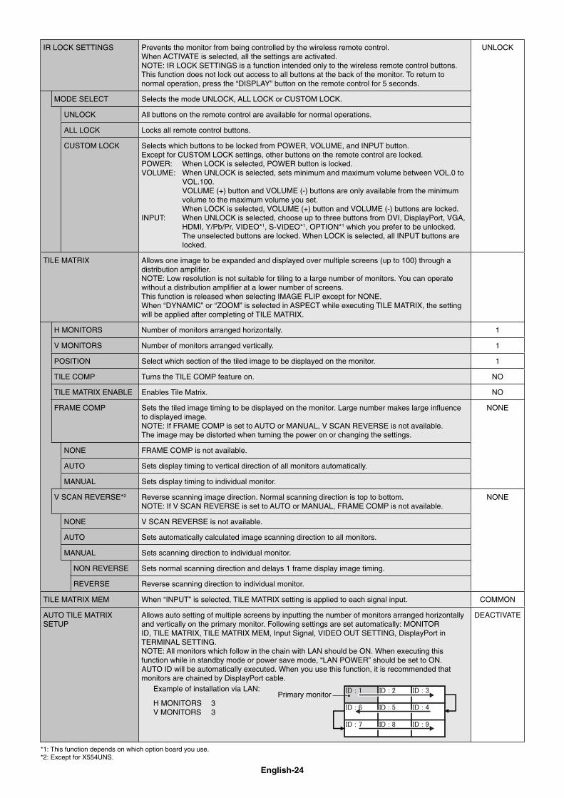
IR LOCK SETTINGS Prevents the monitor from being controlled by the wireless remote control. When ACTIVATE is selected, all the settings are activated.NOTE: IR LOCK SETTINGS is a function intended only to the wireless remote control buttons. This function does not lock out access to all buttons at the back of the monitor. To return to normal operation, press the “DISPLAY” button on the remote control for 5 seconds.
UNLOCK
MODE SELECT Selects the mode UNLOCK, ALL LOCK or CUSTOM LOCK.
UNLOCK All buttons on the remote control are available for normal operations.
ALL LOCK Locks all remote control buttons.
CUSTOM LOCK Selects which buttons to be locked from POWER, VOLUME, and INPUT button.Except for CUSTOM LOCK settings, other buttons on the remote control are locked.POWER: When LOCK is selected, POWER button is locked.VOLUME: When UNLOCK is selected, sets minimum and maximum volume between VOL.0 to VOL.100. VOLUME (+) button and VOLUME (-) buttons are only available from the minimum volume to the maximum volume you set. When LOCK is selected, VOLUME (+) button and VOLUME (-) buttons are locked.INPUT: When UNLOCK is selected, choose up to three buttons from DVI, DisplayPort, VGA, HDMI, Y/Pb/Pr, VIDEO*1, S-VIDEO*1, OPTION*1 which you prefer to be unlocked. The unselected buttons are locked. When LOCK is selected, all INPUT buttons are locked.
TILE MATRIX Allows one image to be expanded and displayed over multiple screens (up to 100) through a distribution amplifi er.NOTE: Low resolution is not suitable for tiling to a large number of monitors. You can operate without a distribution amplifi er at a lower number of screens.This function is released when selecting IMAGE FLIP except for NONE. When “DYNAMIC” or “ZOOM” is selected in ASPECT while executing TILE MATRIX, the setting will be applied after completing of TILE MATRIX.
H MONITORS Number of monitors arranged horizontally. 1
V MONITORS Number of monitors arranged vertically. 1
POSITION Select which section of the tiled image to be displayed on the monitor. 1
TILE COMP Turns the TILE COMP feature on. NO
TILE MATRIX ENABLE Enables Tile Matrix. NO
FRAME COMP Sets the tiled image timing to be displayed on the monitor. Large number makes large infl uence to displayed image.NOTE: If FRAME COMP is set to AUTO or MANUAL, V SCAN REVERSE is not available.The image may be distorted when turning the power on or changing the settings.
NONE
NONE FRAME COMP is not available.
AUTO Sets display timing to vertical direction of all monitors automatically.
MANUAL Sets display timing to individual monitor.
V SCAN REVERSE*2 Reverse scanning image direction. Normal scanning direction is top to bottom. NOTE: If V SCAN REVERSE is set to AUTO or MANUAL, FRAME COMP is not available.
NONE
NONE V SCAN REVERSE is not available.
AUTO Sets automatically calculated image scanning direction to all monitors.
MANUAL Sets scanning direction to individual monitor.
NON REVERSE Sets normal scanning direction and delays 1 frame display image timing.
REVERSE Reverse scanning direction to individual monitor.
TILE MATRIX MEM When “INPUT” is selected, TILE MATRIX setting is applied to each signal input. COMMON
AUTO TILE MATRIX SETUP
Allows auto setting of multiple screens by inputting the number of monitors arranged horizontally and vertically on the primary monitor. Following settings are set automatically: MONITOR ID, TILE MATRIX, TILE MATRIX MEM, Input Signal, VIDEO OUT SETTING, DisplayPort in TERMINAL SETTING.NOTE: All monitors which follow in the chain with LAN should be ON. When executing this function while in standby mode or power save mode, “LAN POWER” should be set to ON. AUTO ID will be automatically executed. When you use this function, it is recommended that monitors are chained by DisplayPort cable.
Example of installation via LAN:
H MONITORS 3V MONITORS 3
Primary monitor
DEACTIVATE
*1: This function depends on which option board you use.*2: Except for X554UNS.
English-25
Eng
lish
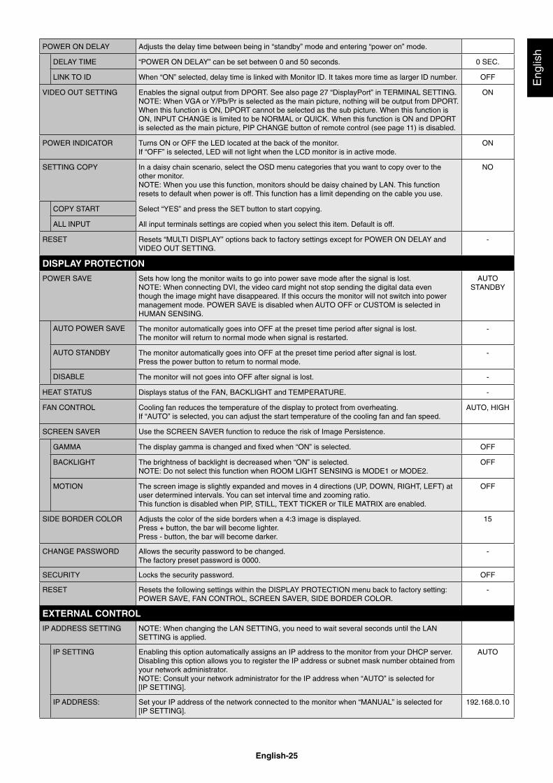
POWER ON DELAY Adjusts the delay time between being in “standby” mode and entering “power on” mode.
DELAY TIME “POWER ON DELAY” can be set between 0 and 50 seconds. 0 SEC.
LINK TO ID When “ON” selected, delay time is linked with Monitor ID. It takes more time as larger ID number. OFF
VIDEO OUT SETTING Enables the signal output from DPORT. See also page 27 “DisplayPort” in TERMINAL SETTING.NOTE: When VGA or Y/Pb/Pr is selected as the main picture, nothing will be output from DPORT. When this function is ON, DPORT cannot be selected as the sub picture. When this function is ON, INPUT CHANGE is limited to be NORMAL or QUICK. When this function is ON and DPORT is selected as the main picture, PIP CHANGE button of remote control (see page 11) is disabled.
ON
POWER INDICATOR Turns ON or OFF the LED located at the back of the monitor.If “OFF” is selected, LED will not light when the LCD monitor is in active mode.
ON
SETTING COPY In a daisy chain scenario, select the OSD menu categories that you want to copy over to the other monitor. NOTE: When you use this function, monitors should be daisy chained by LAN. This function resets to default when power is off. This function has a limit depending on the cable you use.
NO
COPY START Select “YES” and press the SET button to start copying.
ALL INPUT All input terminals settings are copied when you select this item. Default is off.
RESET Resets “MULTI DISPLAY” options back to factory settings except for POWER ON DELAY and VIDEO OUT SETTING.
-
DISPLAY PROTECTION
POWER SAVE Sets how long the monitor waits to go into power save mode after the signal is lost.NOTE: When connecting DVI, the video card might not stop sending the digital data even though the image might have disappeared. If this occurs the monitor will not switch into power management mode. POWER SAVE is disabled when AUTO OFF or CUSTOM is selected in HUMAN SENSING.
AUTO STANDBY
AUTO POWER SAVE The monitor automatically goes into OFF at the preset time period after signal is lost. The monitor will return to normal mode when signal is restarted.
-
AUTO STANDBY The monitor automatically goes into OFF at the preset time period after signal is lost.Press the power button to return to normal mode.
-
DISABLE The monitor will not goes into OFF after signal is lost. -
HEAT STATUS Displays status of the FAN, BACKLIGHT and TEMPERATURE. -
FAN CONTROL Cooling fan reduces the temperature of the display to protect from overheating.If “AUTO” is selected, you can adjust the start temperature of the cooling fan and fan speed.
AUTO, HIGH
SCREEN SAVER Use the SCREEN SAVER function to reduce the risk of Image Persistence.
GAMMA The display gamma is changed and fi xed when “ON” is selected. OFF
BACKLIGHT The brightness of backlight is decreased when “ON” is selected.NOTE: Do not select this function when ROOM LIGHT SENSING is MODE1 or MODE2.
OFF
MOTION The screen image is slightly expanded and moves in 4 directions (UP, DOWN, RIGHT, LEFT) at user determined intervals. You can set interval time and zooming ratio.This function is disabled when PIP, STILL, TEXT TICKER or TILE MATRIX are enabled.
OFF
SIDE BORDER COLOR Adjusts the color of the side borders when a 4:3 image is displayed.Press + button, the bar will become lighter.Press - button, the bar will become darker.
15
CHANGE PASSWORD Allows the security password to be changed.The factory preset password is 0000.
-
SECURITY Locks the security password. OFF
RESET Resets the following settings within the DISPLAY PROTECTION menu back to factory setting: POWER SAVE, FAN CONTROL, SCREEN SAVER, SIDE BORDER COLOR.
-
EXTERNAL CONTROL
IP ADDRESS SETTING NOTE: When changing the LAN SETTING, you need to wait several seconds until the LAN SETTING is applied.
IP SETTING Enabling this option automatically assigns an IP address to the monitor from your DHCP server.Disabling this option allows you to register the IP address or subnet mask number obtained from your network administrator.NOTE: Consult your network administrator for the IP address when “AUTO” is selected for [IP SETTING].
AUTO
IP ADDRESS: Set your IP address of the network connected to the monitor when “MANUAL” is selected for [IP SETTING].
192.168.0.10
English-26
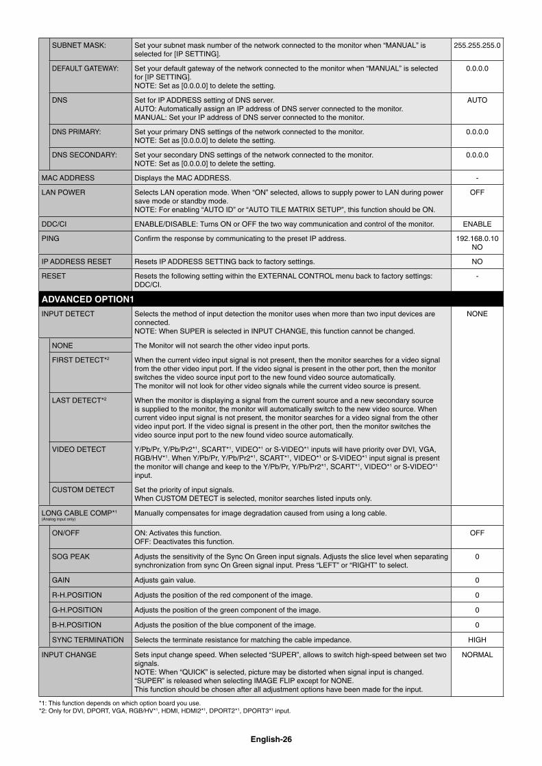
SUBNET MASK: Set your subnet mask number of the network connected to the monitor when “MANUAL” is selected for [IP SETTING].
255.255.255.0
DEFAULT GATEWAY: Set your default gateway of the network connected to the monitor when “MANUAL” is selected for [IP SETTING].NOTE: Set as [0.0.0.0] to delete the setting.
0.0.0.0
DNS Set for IP ADDRESS setting of DNS server.AUTO: Automatically assign an IP address of DNS server connected to the monitor.MANUAL: Set your IP address of DNS server connected to the monitor.
AUTO
DNS PRIMARY: Set your primary DNS settings of the network connected to the monitor.NOTE: Set as [0.0.0.0] to delete the setting.
0.0.0.0
DNS SECONDARY: Set your secondary DNS settings of the network connected to the monitor.NOTE: Set as [0.0.0.0] to delete the setting.
0.0.0.0
MAC ADDRESS Displays the MAC ADDRESS. -
LAN POWER Selects LAN operation mode. When “ON” selected, allows to supply power to LAN during power save mode or standby mode.NOTE: For enabling “AUTO ID” or “AUTO TILE MATRIX SETUP”, this function should be ON.
OFF
DDC/CI ENABLE/DISABLE: Turns ON or OFF the two way communication and control of the monitor. ENABLE
PING Confi rm the response by communicating to the preset IP address. 192.168.0.10NO
IP ADDRESS RESET Resets IP ADDRESS SETTING back to factory settings. NO
RESET Resets the following setting within the EXTERNAL CONTROL menu back to factory settings: DDC/CI.
-
ADVANCED OPTION1
INPUT DETECT Selects the method of input detection the monitor uses when more than two input devices are connected.NOTE: When SUPER is selected in INPUT CHANGE, this function cannot be changed.
NONE
NONE The Monitor will not search the other video input ports.
FIRST DETECT*2 When the current video input signal is not present, then the monitor searches for a video signal from the other video input port. If the video signal is present in the other port, then the monitor switches the video source input port to the new found video source automatically. The monitor will not look for other video signals while the current video source is present.
LAST DETECT*2 When the monitor is displaying a signal from the current source and a new secondary source is supplied to the monitor, the monitor will automatically switch to the new video source. When current video input signal is not present, the monitor searches for a video signal from the other video input port. If the video signal is present in the other port, then the monitor switches the video source input port to the new found video source automatically.
VIDEO DETECT Y/Pb/Pr, Y/Pb/Pr2*1, SCART*1, VIDEO*1 or S-VIDEO*1 inputs will have priority over DVI, VGA, RGB/HV*1. When Y/Pb/Pr, Y/Pb/Pr2*1, SCART*1, VIDEO*1 or S-VIDEO*1 input signal is present the monitor will change and keep to the Y/Pb/Pr, Y/Pb/Pr2*1, SCART*1, VIDEO*1 or S-VIDEO*1 input.
CUSTOM DETECT Set the priority of input signals.When CUSTOM DETECT is selected, monitor searches listed inputs only.
LONG CABLE COMP*1
(Analog input only)Manually compensates for image degradation caused from using a long cable.
ON/OFF ON: Activates this function.OFF: Deactivates this function.
OFF
SOG PEAK Adjusts the sensitivity of the Sync On Green input signals. Adjusts the slice level when separating synchronization from sync On Green signal input. Press “LEFT” or “RIGHT” to select.
0
GAIN Adjusts gain value. 0
R-H.POSITION Adjusts the position of the red component of the image. 0
G-H.POSITION Adjusts the position of the green component of the image. 0
B-H.POSITION Adjusts the position of the blue component of the image. 0
SYNC TERMINATION Selects the terminate resistance for matching the cable impedance. HIGH
INPUT CHANGE Sets input change speed. When selected “SUPER”, allows to switch high-speed between set two signals.NOTE: When “QUICK” is selected, picture may be distorted when signal input is changed. “SUPER” is released when selecting IMAGE FLIP except for NONE.This function should be chosen after all adjustment options have been made for the input.
NORMAL
*1: This function depends on which option board you use.*2: Only for DVI, DPORT, VGA, RGB/HV*1, HDMI, HDMI2*1, DPORT2*1, DPORT3*1 input.
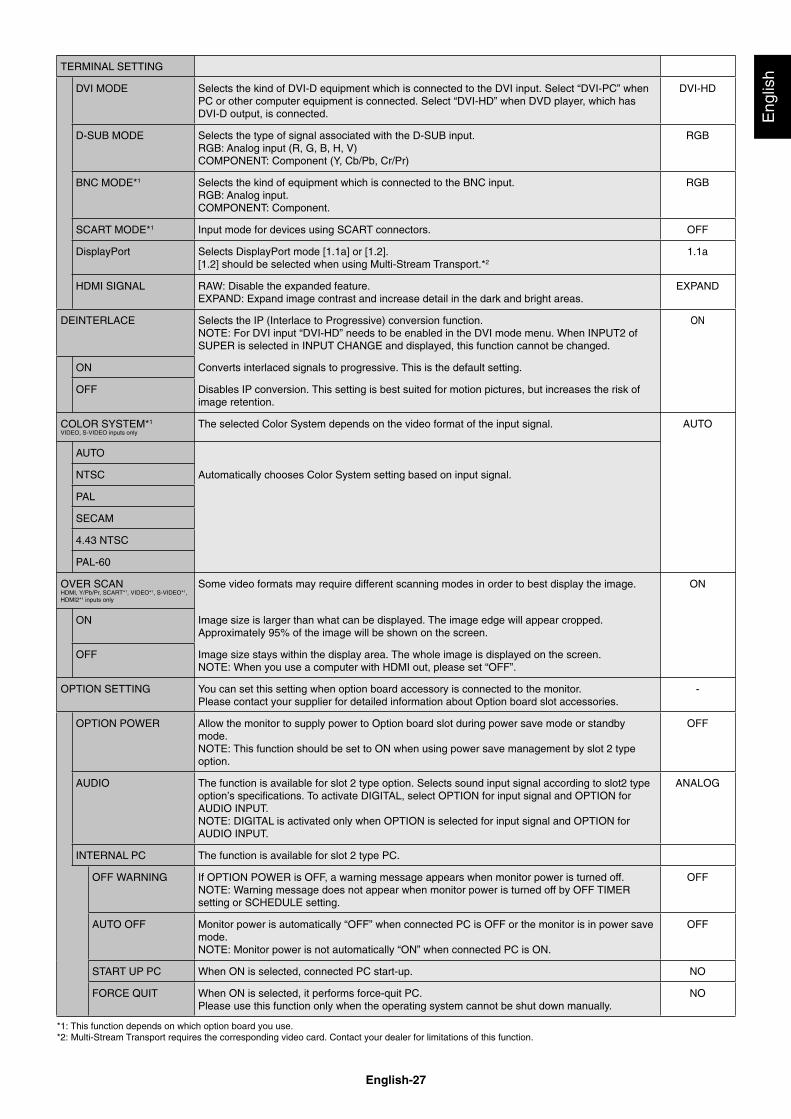
English-27
Eng
lish
TERMINAL SETTING
DVI MODE Selects the kind of DVI-D equipment which is connected to the DVI input. Select “DVI-PC” when PC or other computer equipment is connected. Select “DVI-HD” when DVD player, which has DVI-D output, is connected.
DVI-HD
D-SUB MODE Selects the type of signal associated with the D-SUB input.RGB: Analog input (R, G, B, H, V)COMPONENT: Component (Y, Cb/Pb, Cr/Pr)
RGB
BNC MODE*1 Selects the kind of equipment which is connected to the BNC input.RGB: Analog input.COMPONENT: Component.
RGB
SCART MODE*1 Input mode for devices using SCART connectors. OFF
DisplayPort Selects DisplayPort mode [1.1a] or [1.2]. [1.2] should be selected when using Multi-Stream Transport.*2
1.1a
HDMI SIGNAL RAW: Disable the expanded feature.EXPAND: Expand image contrast and increase detail in the dark and bright areas.
EXPAND
DEINTERLACE Selects the IP (Interlace to Progressive) conversion function.NOTE: For DVI input “DVI-HD” needs to be enabled in the DVI mode menu. When INPUT2 of SUPER is selected in INPUT CHANGE and displayed, this function cannot be changed.
ON
ON Converts interlaced signals to progressive. This is the default setting.
OFF Disables IP conversion. This setting is best suited for motion pictures, but increases the risk of image retention.
COLOR SYSTEM*1
VIDEO, S-VIDEO inputs onlyThe selected Color System depends on the video format of the input signal. AUTO
AUTO
NTSC Automatically chooses Color System setting based on input signal.
PAL
SECAM
4.43 NTSC
PAL-60
OVER SCANHDMI, Y/Pb/Pr, SCART*1, VIDEO*1, S-VIDEO*1, HDMI2*1 inputs only
Some video formats may require different scanning modes in order to best display the image. ON
ON Image size is larger than what can be displayed. The image edge will appear cropped.Approximately 95% of the image will be shown on the screen.
OFF Image size stays within the display area. The whole image is displayed on the screen.NOTE: When you use a computer with HDMI out, please set “OFF”.
OPTION SETTING You can set this setting when option board accessory is connected to the monitor.Please contact your supplier for detailed information about Option board slot accessories.
-
OPTION POWER Allow the monitor to supply power to Option board slot during power save mode or standby mode.NOTE: This function should be set to ON when using power save management by slot 2 type option.
OFF
AUDIO The function is available for slot 2 type option. Selects sound input signal according to slot2 type option’s specifi cations. To activate DIGITAL, select OPTION for input signal and OPTION for AUDIO INPUT.NOTE: DIGITAL is activated only when OPTION is selected for input signal and OPTION for AUDIO INPUT.
ANALOG
INTERNAL PC The function is available for slot 2 type PC.
OFF WARNING If OPTION POWER is OFF, a warning message appears when monitor power is turned off.NOTE: Warning message does not appear when monitor power is turned off by OFF TIMER setting or SCHEDULE setting.
OFF
AUTO OFF Monitor power is automatically “OFF” when connected PC is OFF or the monitor is in power save mode.NOTE: Monitor power is not automatically “ON” when connected PC is ON.
OFF
START UP PC When ON is selected, connected PC start-up. NO
FORCE QUIT When ON is selected, it performs force-quit PC.Please use this function only when the operating system cannot be shut down manually.
NO
*1: This function depends on which option board you use.*2: Multi-Stream Transport requires the corresponding video card. Contact your dealer for limitations of this function.
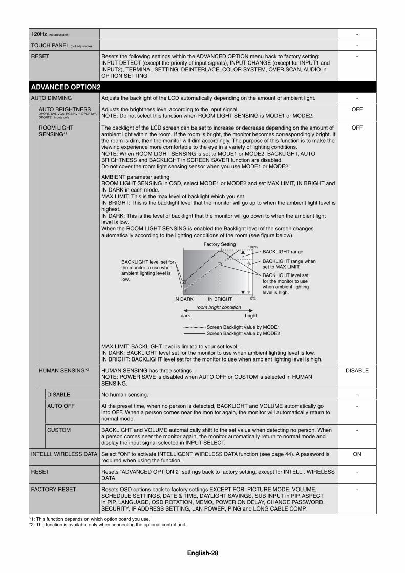
English-28
120Hz (not adjustable) -
TOUCH PANEL (not adjustable) -
RESET Resets the following settings within the ADVANCED OPTION menu back to factory setting: INPUT DETECT (except the priority of input signals), INPUT CHANGE (except for INPUT1 and INPUT2), TERMINAL SETTING, DEINTERLACE, COLOR SYSTEM, OVER SCAN, AUDIO in OPTION SETTING.
-
ADVANCED OPTION2
AUTO DIMMING Adjusts the backlight of the LCD automatically depending on the amount of ambient light. -
AUTO BRIGHTNESSDPORT, DVI, VGA, RGB/HV*1, DPORT2*1, DPORT3*1 inputs only
Adjusts the brightness level according to the input signal.NOTE: Do not select this function when ROOM LIGHT SENSING is MODE1 or MODE2.
OFF
ROOM LIGHT SENSING*2
The backlight of the LCD screen can be set to increase or decrease depending on the amount of ambient light within the room. If the room is bright, the monitor becomes correspondingly bright. If the room is dim, then the monitor will dim accordingly. The purpose of this function is to make the viewing experience more comfortable to the eye in a variety of lighting conditions.NOTE: When ROOM LIGHT SENSING is set to MODE1 or MODE2, BACKLIGHT, AUTO BRIGHTNESS and BACKLIGHT in SCREEN SAVER function are disabled.Do not cover the room light sensing sensor when you use MODE1 or MODE2.
AMBIENT parameter settingROOM LIGHT SENSING in OSD, select MODE1 or MODE2 and set MAX LIMIT, IN BRIGHT and IN DARK in each mode.MAX LIMIT: This is the max level of backlight which you set.IN BRIGHT: This is the backlight level that the monitor will go up to when the ambient light level is highest.IN DARK: This is the level of backlight that the monitor will go down to when the ambient light level is low.When the ROOM LIGHT SENSING is enabled the Backlight level of the screen changes automatically according to the lighting conditions of the room (see fi gure below).
BACKLIGHT level set for the monitor to use when ambient lighting level is low.
BACKLIGHT level set for the monitor to use when ambient lighting level is high.
BACKLIGHT range
dark bright
room bright condition
Screen Backlight value by MODE2
IN DARK IN BRIGHT
Screen Backlight value by MODE1
Factory Setting
BACKLIGHT range when set to MAX LIMIT.
MAX LIMIT: BACKLIGHT level is limited to your set level.IN DARK: BACKLIGHT level set for the monitor to use when ambient lighting level is low.IN BRIGHT: BACKLIGHT level set for the monitor to use when ambient lighting level is high.
OFF
HUMAN SENSING*2 HUMAN SENSING has three settings.NOTE: POWER SAVE is disabled when AUTO OFF or CUSTOM is selected in HUMAN SENSING.
DISABLE
DISABLE No human sensing. -
AUTO OFF At the preset time, when no person is detected, BACKLIGHT and VOLUME automatically go into OFF. When a person comes near the monitor again, the monitor will automatically return to normal mode.
-
CUSTOM BACKLIGHT and VOLUME automatically shift to the set value when detecting no person. When a person comes near the monitor again, the monitor automatically return to normal mode and display the input signal selected in INPUT SELECT.
-
INTELLI. WIRELESS DATA Select “ON” to activate INTELLIGENT WIRELESS DATA function (see page 44). A password is required when using the function.
ON
RESET Resets “ADVANCED OPTION 2” settings back to factory setting, except for INTELLI. WIRELESS DATA.
-
FACTORY RESET Resets OSD options back to factory settings EXCEPT FOR: PICTURE MODE, VOLUME, SCHEDULE SETTINGS, DATE & TIME, DAYLIGHT SAVINGS, SUB INPUT in PIP, ASPECT in PIP, LANGUAGE, OSD ROTATION, MEMO, POWER ON DELAY, CHANGE PASSWORD, SECURITY, IP ADDRESS SETTING, LAN POWER, PING and LONG CABLE COMP.
-
*1: This function depends on which option board you use.*2: The function is available only when connecting the optional control unit.
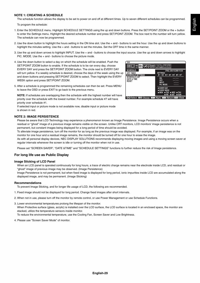
English-29
Eng
lish
NOTE 1: CREATING A SCHEDULEThe schedule function allows the display to be set to power on and off at different times. Up to seven different schedules can be programmed.
To program the schedule:
1. Enter the SCHEDULE menu. Highlight SCHEDULE SETTINGS using the up and down buttons. Press the SET/POINT ZOOM or the + button to enter the Settings menu. Highlight the desired schedule number and press SET/POINT ZOOM. The box next to the number will turn yellow. The schedule can now be programmed.
2. Use the down button to highlight the hours setting in the ON time slot. Use the + and - buttons to set the hour. Use the up and down buttons to highlight the minutes setting. Use the + and - buttons to set the minutes. Set the OFF time in the same manner.
3. Use the up and down arrows to highlight INPUT. Use the + and - buttons to choose the input source. Use the up and down arrows to highlight PIC. MODE. Use the + and - buttons to choose the picture mode.
4. Use the down button to select a day on which the schedule will be enabled. Push the SET/POINT ZOOM button to enable. If the schedule is to be ran every day, choose EVERY DAY and press the SET/POINT ZOOM button. The circle next to EVERY DAY will turn yellow. If a weekly schedule is desired, choose the days of the week using the up and down buttons and pressing SET/POINT ZOOM to select. Then highlight the EVERY WEEK option and press SET/POINT ZOOM.
5. After a schedule is programmed the remaining schedules can then be set. Press MENU to leave the OSD or press EXIT to go back to the previous menu.
NOTE: If schedules are overlapping then the schedule with the highest number will have priority over the schedule with the lowest number. For example schedule #7 will have priority over schedule #1.If selected input or picture mode is not available now, disable input or picture mode is shown in red.
NOTE 2: IMAGE PERSISTENCE Please be aware that LCD Technology may experience a phenomenon known as Image Persistence. Image Persistence occurs when a residual or “ghost” image of a previous image remains visible on the screen. Unlike CRT monitors, LCD monitors’ image persistence is not permanent, but constant images being displayed for a long period of time should be avoided.To alleviate image persistence, turn off the monitor for as long as the previous image was displayed. For example, if an image was on the monitor for one hour and a residual image remains, the monitor should be turned off for one hour to erase the image.As with all personal display devices, NEC DISPLAY SOLUTIONS recommends displaying moving images and using a moving screen saver at regular intervals whenever the screen is idle or turning off the monitor when not in use.
Please set “SCREEN SAVER”, “DATE &TIME” and “SCHEDULE SETTINGS” functions to further reduce the risk of Image persistence.
For long life use as Public Display
Image Sticking of LCD PanelWhen an LCD panel is operated continuously for long hours, a trace of electric charge remains near the electrode inside LCD, and residual or “ghost” image of previous image may be observed. (Image Persistence)Image Persistence is not permanent, but when fi xed image is displayed for long period, ionic impurities inside LCD are accumulated along the displayed image, and may be permanent. (Image Sticking)
RecommendationsTo prevent Image Sticking, and for longer life usage of LCD, the following are recommended.
1. Fixed image should not be displayed for long period. Change fi xed images after short intervals.
2. When not in use, please turn off the monitor by remote control, or use Power Management or use Schedule Functions.
3. Lower environmental temperatures prolong the lifespan of the monitor.When Protective surface (glass, acrylic) is installed over the LCD surface, the LCD surface is located in an enclosed space, the monitor are stacked, utilize the temperature sensors inside monitor.To reduce the environmental temperature, use the Cooling Fan, Screen Saver and Low Brightness.
4. Please use “Screen Saver Mode” of monitor.
SCHEDULE:
ON: – – : – –OFF: – – : – –
– – – –INPUT:PIC. MODE: – – – –
DVI
(THU) JUN.18.2009 15:38 SETTINGS:OFF TIMER
SCHEDULE SETTINGSSCHEDULE LISTDATE & TIMERESET
MON TUE WED THUSAT SUNFRI
1 2 3 4 5 6 7
Choose Mark Return Close
EVERY DAYEVERY WEEK
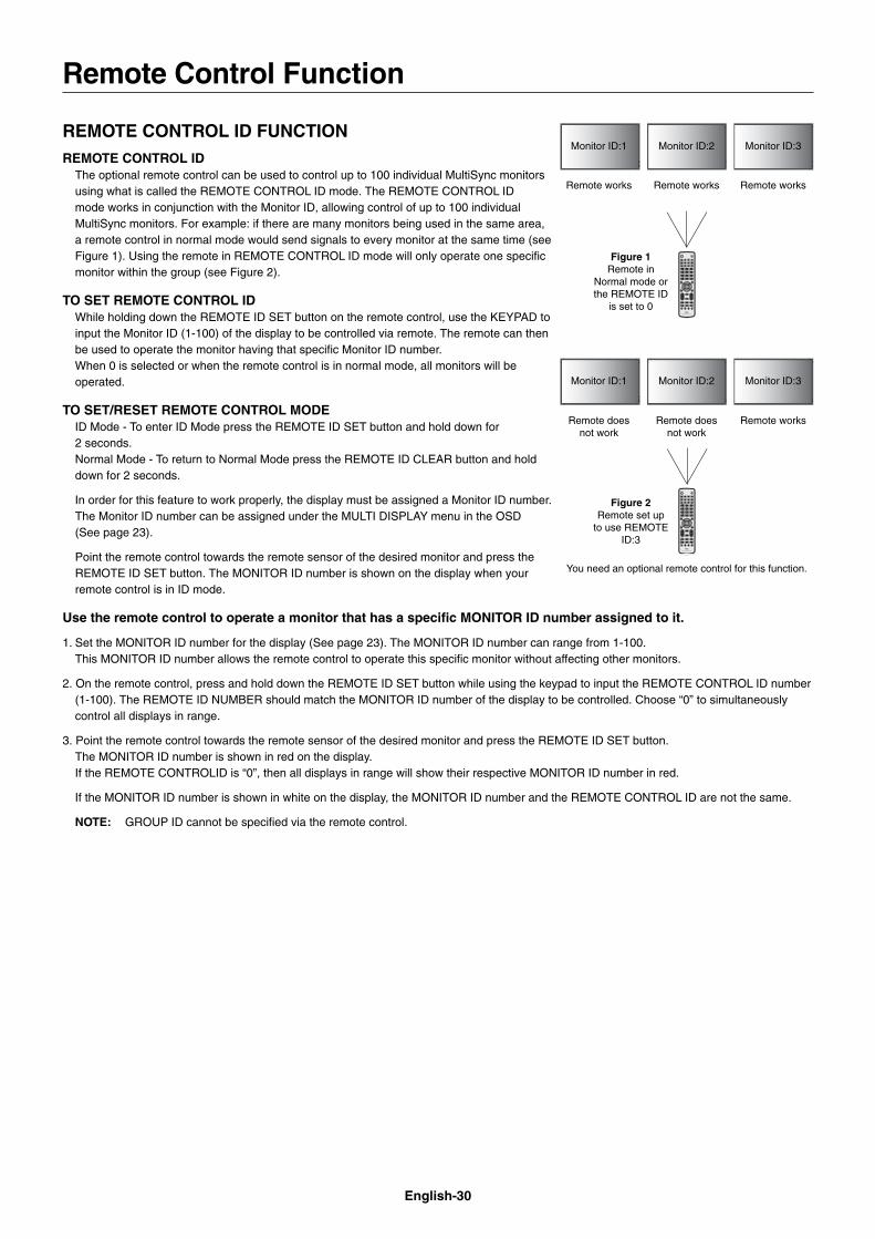
English-30
REMOTE CONTROL ID FUNCTIONREMOTE CONTROL ID
The optional remote control can be used to control up to 100 individual MultiSync monitors using what is called the REMOTE CONTROL ID mode. The REMOTE CONTROL ID mode works in conjunction with the Monitor ID, allowing control of up to 100 individual MultiSync monitors. For example: if there are many monitors being used in the same area, a remote control in normal mode would send signals to every monitor at the same time (see Figure 1). Using the remote in REMOTE CONTROL ID mode will only operate one specifi c monitor within the group (see Figure 2).
TO SET REMOTE CONTROL IDWhile holding down the REMOTE ID SET button on the remote control, use the KEYPAD to input the Monitor ID (1-100) of the display to be controlled via remote. The remote can then be used to operate the monitor having that specifi c Monitor ID number. When 0 is selected or when the remote control is in normal mode, all monitors will be operated.
TO SET/RESET REMOTE CONTROL MODEID Mode - To enter ID Mode press the REMOTE ID SET button and hold down for 2 seconds. Normal Mode - To return to Normal Mode press the REMOTE ID CLEAR button and hold down for 2 seconds.
In order for this feature to work properly, the display must be assigned a Monitor ID number. The Monitor ID number can be assigned under the MULTI DISPLAY menu in the OSD (See page 23).
Point the remote control towards the remote sensor of the desired monitor and press the REMOTE ID SET button. The MONITOR ID number is shown on the display when your remote control is in ID mode.
Use the remote control to operate a monitor that has a specifi c MONITOR ID number assigned to it.
1. Set the MONITOR ID number for the display (See page 23). The MONITOR ID number can range from 1-100.This MONITOR ID number allows the remote control to operate this specifi c monitor without affecting other monitors.
2. On the remote control, press and hold down the REMOTE ID SET button while using the keypad to input the REMOTE CONTROL ID number (1-100). The REMOTE ID NUMBER should match the MONITOR ID number of the display to be controlled. Choose “0” to simultaneously control all displays in range.
3. Point the remote control towards the remote sensor of the desired monitor and press the REMOTE ID SET button.The MONITOR ID number is shown in red on the display.If the REMOTE CONTROLID is “0”, then all displays in range will show their respective MONITOR ID number in red.
If the MONITOR ID number is shown in white on the display, the MONITOR ID number and the REMOTE CONTROL ID are not the same.
NOTE: GROUP ID cannot be specifi ed via the remote control.
Remote Control Function
Monitor ID:1 Monitor ID:2 Monitor ID:3
Monitor ID:1 Monitor ID:2 Monitor ID:3
Remote does not work
Remote does not work
Remote works
Remote works Remote works Remote works
Figure 1Remote in
Normal mode or the REMOTE ID
is set to 0
Figure 2Remote set up
to use REMOTE ID:3
You need an optional remote control for this function.
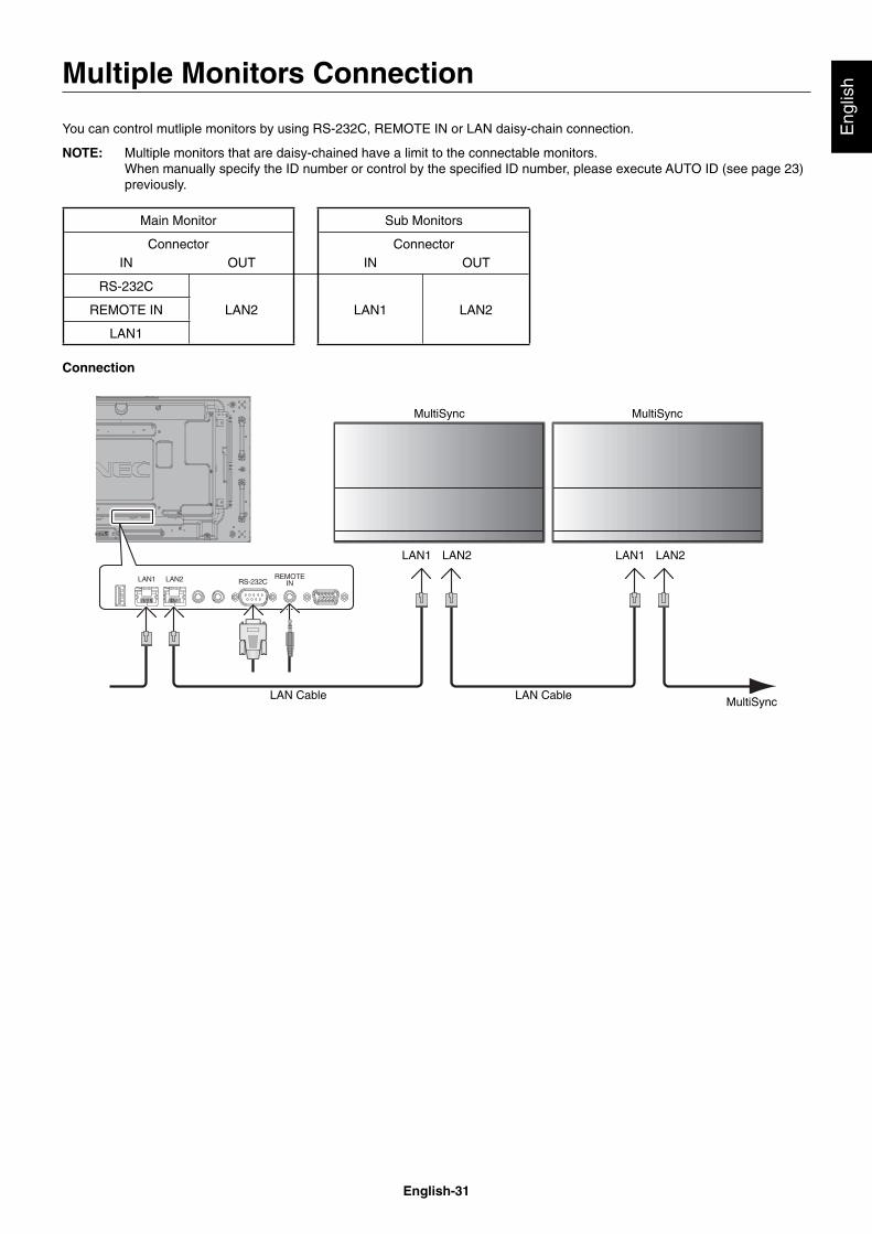
English-31
Eng
lish
You can control mutliple monitors by using RS-232C, REMOTE IN or LAN daisy-chain connection.
NOTE: Multiple monitors that are daisy-chained have a limit to the connectable monitors.When manually specify the ID number or control by the specifi ed ID number, please execute AUTO ID (see page 23) previously.
Main Monitor Sub Monitors
Connector ConnectorIN OUT IN OUT
RS-232C
LAN2 LAN1 LAN2REMOTE IN
LAN1
Connection
LAN1
LAN Cable
MultiSync MultiSync
LAN2 LAN1 LAN2
MultiSyncLAN Cable
Multiple Monitors Connection
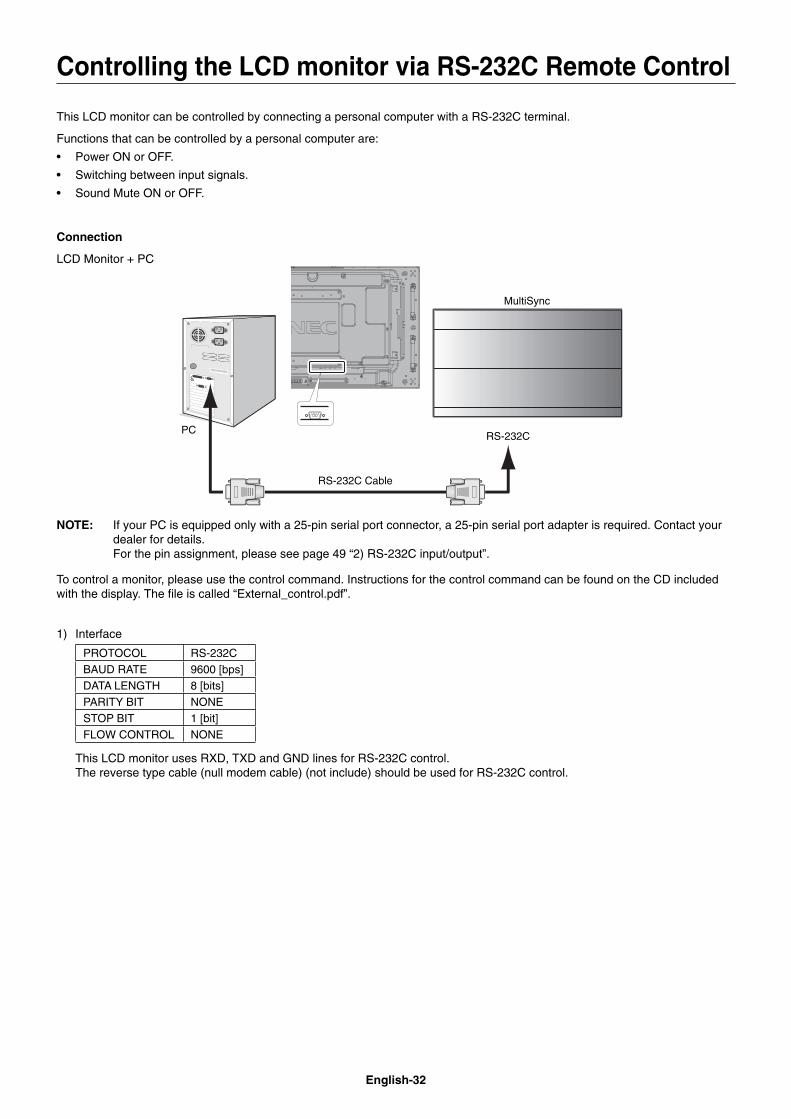
English-32
This LCD monitor can be controlled by connecting a personal computer with a RS-232C terminal.
Functions that can be controlled by a personal computer are:
• Power ON or OFF.
• Switching between input signals.
• Sound Mute ON or OFF.
Connection
LCD Monitor + PC
RS-232C Cable
PCRS-232C
MultiSync
NOTE: If your PC is equipped only with a 25-pin serial port connector, a 25-pin serial port adapter is required. Contact your dealer for details.For the pin assignment, please see page 49 “2) RS-232C input/output”.
To control a monitor, please use the control command. Instructions for the control command can be found on the CD included with the display. The fi le is called “External_control.pdf”.
1) Interface
PROTOCOL RS-232CBAUD RATE 9600 [bps]DATA LENGTH 8 [bits]PARITY BIT NONESTOP BIT 1 [bit]FLOW CONTROL NONE
This LCD monitor uses RXD, TXD and GND lines for RS-232C control.The reverse type cable (null modem cable) (not include) should be used for RS-232C control.
Controlling the LCD monitor via RS-232C Remote Control
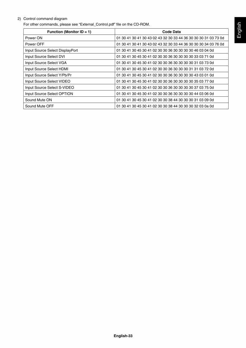
English-33
Eng
lish
2) Control command diagram
For other commands, please see “External_Control.pdf” fi le on the CD-ROM.
Function (Monitor ID = 1) Code Data
Power ON 01 30 41 30 41 30 43 02 43 32 30 33 44 36 30 30 30 31 03 73 0d
Power OFF 01 30 41 30 41 30 43 02 43 32 30 33 44 36 30 30 30 34 03 76 0d
Input Source Select DisplayPort 01 30 41 30 45 30 41 02 30 30 36 30 30 30 30 46 03 04 0d
Input Source Select DVI 01 30 41 30 45 30 41 02 30 30 36 30 30 30 30 33 03 71 0d
Input Source Select VGA 01 30 41 30 45 30 41 02 30 30 36 30 30 30 30 31 03 73 0d
Input Source Select HDMI 01 30 41 30 45 30 41 02 30 30 36 30 30 30 31 31 03 72 0d
Input Source Select Y/Pb/Pr 01 30 41 30 45 30 41 02 30 30 36 30 30 30 30 43 03 01 0d
Input Source Select VIDEO 01 30 41 30 45 30 41 02 30 30 36 30 30 30 30 35 03 77 0d
Input Source Select S-VIDEO 01 30 41 30 45 30 41 02 30 30 36 30 30 30 30 37 03 75 0d
Input Source Select OPTION 01 30 41 30 45 30 41 02 30 30 36 30 30 30 30 44 03 06 0d
Sound Mute ON 01 30 41 30 45 30 41 02 30 30 38 44 30 30 30 31 03 09 0d
Sound Mute OFF 01 30 41 30 45 30 41 02 30 30 38 44 30 30 30 32 03 0a 0d
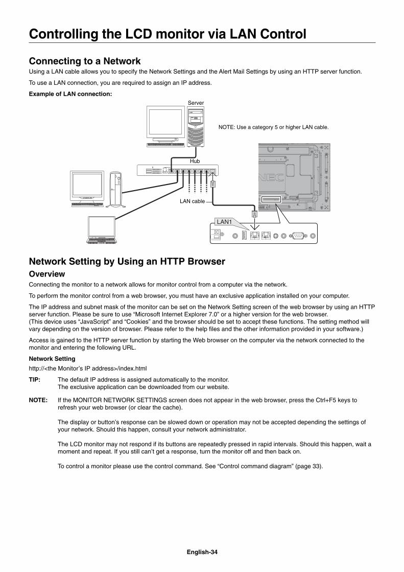
English-34
Connecting to a NetworkUsing a LAN cable allows you to specify the Network Settings and the Alert Mail Settings by using an HTTP server function.
To use a LAN connection, you are required to assign an IP address.
Example of LAN connection:Server
Hub
NOTE: Use a category 5 or higher LAN cable.
LAN cable
Network Setting by Using an HTTP BrowserOverviewConnecting the monitor to a network allows for monitor control from a computer via the network.
To perform the monitor control from a web browser, you must have an exclusive application installed on your computer.
The IP address and subnet mask of the monitor can be set on the Network Setting screen of the web browser by using an HTTP server function. Please be sure to use “Microsoft Internet Explorer 7.0” or a higher version for the web browser.(This device uses “JavaScript” and “Cookies” and the browser should be set to accept these functions. The setting method will vary depending on the version of browser. Please refer to the help fi les and the other information provided in your software.)
Access is gained to the HTTP server function by starting the Web browser on the computer via the network connected to the monitor and entering the following URL.
Network Setting
http://<the Monitor’s IP address>/index.html
TIP: The default IP address is assigned automatically to the monitor.The exclusive application can be downloaded from our website.
NOTE: If the MONITOR NETWORK SETTINGS screen does not appear in the web browser, press the Ctrl+F5 keys to refresh your web browser (or clear the cache).
The display or button’s response can be slowed down or operation may not be accepted depending the settings of your network. Should this happen, consult your network administrator.
The LCD monitor may not respond if its buttons are repeatedly pressed in rapid intervals. Should this happen, wait a moment and repeat. If you still can’t get a response, turn the monitor off and then back on.
To control a monitor please use the control command. See “Control command diagram” (page 33).
Controlling the LCD monitor via LAN Control
English-35
Eng
lish
Preparation Before UseConnect the monitor to a commercially available LAN cable before engaging in browser operations.
Operation with a browser that uses a proxy server may not be possible depending on the type of proxy server and the setting method. Although the type of proxy server will be a factor, it is possible that items that have actually been set will not be displayed depending on the effectiveness of the cache, and the contents set from the browser may not be refl ected in operation. It is recommended that a proxy server not be used unless it is unavailable.
Handling of the Address for Operation via a BrowserThe host name can be used under the following cases:If the host name corresponding to the IP address of the monitor has been registered to the domain name server (DNS) by the network administrator, you can then access the network settings of the display via that registered host name using a compatible browser.If the host name corresponding to the IP address of the monitor has been confi gured in the “HOSTS” fi le of the computer being used, you can then access the network settings of the display via that host name using a compatible browser.
Example 1: When the host name of the monitor has been set to “pd.nec.co.jp”, access is gained to the network setting by specifying http://pd.nec.co.jp/index.html for the address or the entry column of the URL.
Example 2: When the IP address of the monitor is “192.168.73.1”, access is gained to the mail alert settings by specifying http://192.168.73.1/index.html for the address or the entry column of the URL.
OperationAccess the following address to show HOME. Click each link on the left side of HOME.
http://<the Monitor’s IP address>/index.html
REMOTE CONTROLEnable to control equivalent as the remote control key.
OSD menuEnable to set the following OSD menu.
PICTURE, ADJUST, AUDIO, SCHEDULE, PIP, OSD, MULTI DISPLAY, DISPLAY PROTECTION, EXTERNAL CONTROL, ADVANCED OPTION1, ADVANCED OPTION2.
NOTE: Function of buttons which are shown on setting pages.[APPLY]: Refl ect your settings.[CANCEL]: Return to the previous settings. NOTE: CANCEL is disabled after clicking APPLY.[RELOAD]: Reload the settings.[RESET]: Resets to the initial setting.
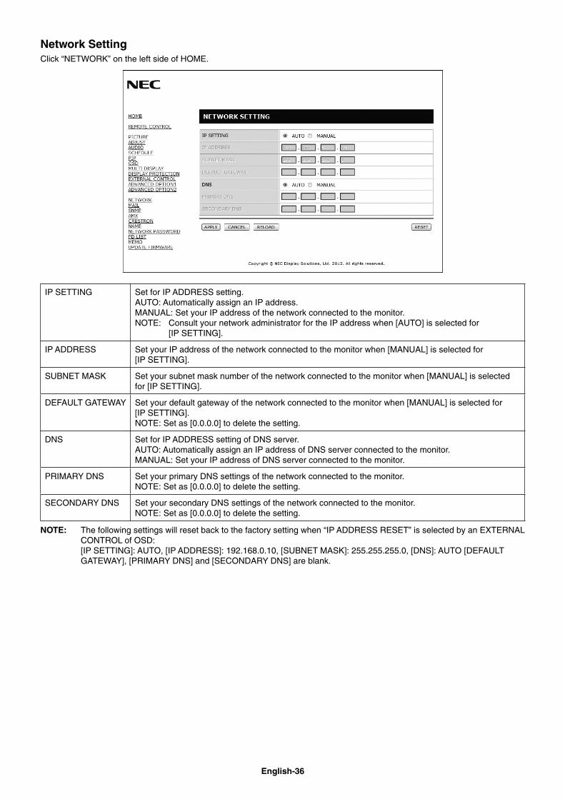
English-36
Network SettingClick “NETWORK” on the left side of HOME.
IP SETTING Set for IP ADDRESS setting.AUTO: Automatically assign an IP address.MANUAL: Set your IP address of the network connected to the monitor.NOTE: Consult your network administrator for the IP address when [AUTO] is selected for [IP SETTING].
IP ADDRESS Set your IP address of the network connected to the monitor when [MANUAL] is selected for [IP SETTING].
SUBNET MASK Set your subnet mask number of the network connected to the monitor when [MANUAL] is selected for [IP SETTING].
DEFAULT GATEWAY Set your default gateway of the network connected to the monitor when [MANUAL] is selected for [IP SETTING].NOTE: Set as [0.0.0.0] to delete the setting.
DNS Set for IP ADDRESS setting of DNS server.AUTO: Automatically assign an IP address of DNS server connected to the monitor.MANUAL: Set your IP address of DNS server connected to the monitor.
PRIMARY DNS Set your primary DNS settings of the network connected to the monitor.NOTE: Set as [0.0.0.0] to delete the setting.
SECONDARY DNS Set your secondary DNS settings of the network connected to the monitor.NOTE: Set as [0.0.0.0] to delete the setting.
NOTE: The following settings will reset back to the factory setting when “IP ADDRESS RESET” is selected by an EXTERNAL CONTROL of OSD: [IP SETTING]: AUTO, [IP ADDRESS]: 192.168.0.10, [SUBNET MASK]: 255.255.255.0, [DNS]: AUTO [DEFAULT GATEWAY], [PRIMARY DNS] and [SECONDARY DNS] are blank.
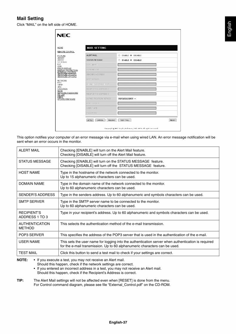
English-37
Eng
lish
Mail SettingClick “MAIL” on the left side of HOME.
This option notifi es your computer of an error message via e-mail when using wired LAN. An error message notifi cation will be sent when an error occurs in the monitor.
ALERT MAIL Checking [ENABLE] will turn on the Alert Mail feature.Checking [DISABLE] will turn off the Alert Mail feature.
STATUS MESSAGE Checking [ENABLE] will turn on the STATUS MESSAGE feature.Checking [DISABLE] will turn off the STATUS MESSAGE feature.
HOST NAME Type in the hostname of the network connected to the monitor.Up to 15 alphanumeric characters can be used.
DOMAIN NAME Type in the domain name of the network connected to the monitor.Up to 60 alphanumeric characters can be used.
SENDER’S ADDRESS Type in the senders address. Up to 60 alphanumeric and symbols characters can be used.
SMTP SERVER Type in the SMTP server name to be connected to the monitor.Up to 60 alphanumeric characters can be used.
RECIPIENT’S ADDRESS 1 TO 3
Type in your recipient’s address. Up to 60 alphanumeric and symbols characters can be used.
AUTHENTICATION METHOD
This selects the authentication method of the e-mail transmission.
POP3 SERVER This specifi es the address of the POP3 server that is used in the authentication of the e-mail.
USER NAME This sets the user name for logging into the authentication server when authentication is required for the e-mail transmission. Up to 60 alphanumeric characters can be used.
TEST MAIL Click this button to send a test mail to check if your settings are correct.
NOTE: • If you execute a test, you may not receive an Alert mail. Should this happen, check if the network settings are correct.• If you entered an incorrect address in a test, you may not receive an Alert mail. Should this happen, check if the Recipient’s Address is correct.
TIP: The Alert Mail settings will not be affected even when [RESET] is done from the menu.For Control command diagram, please see fi le “External_Control.pdf” on the CD-ROM.
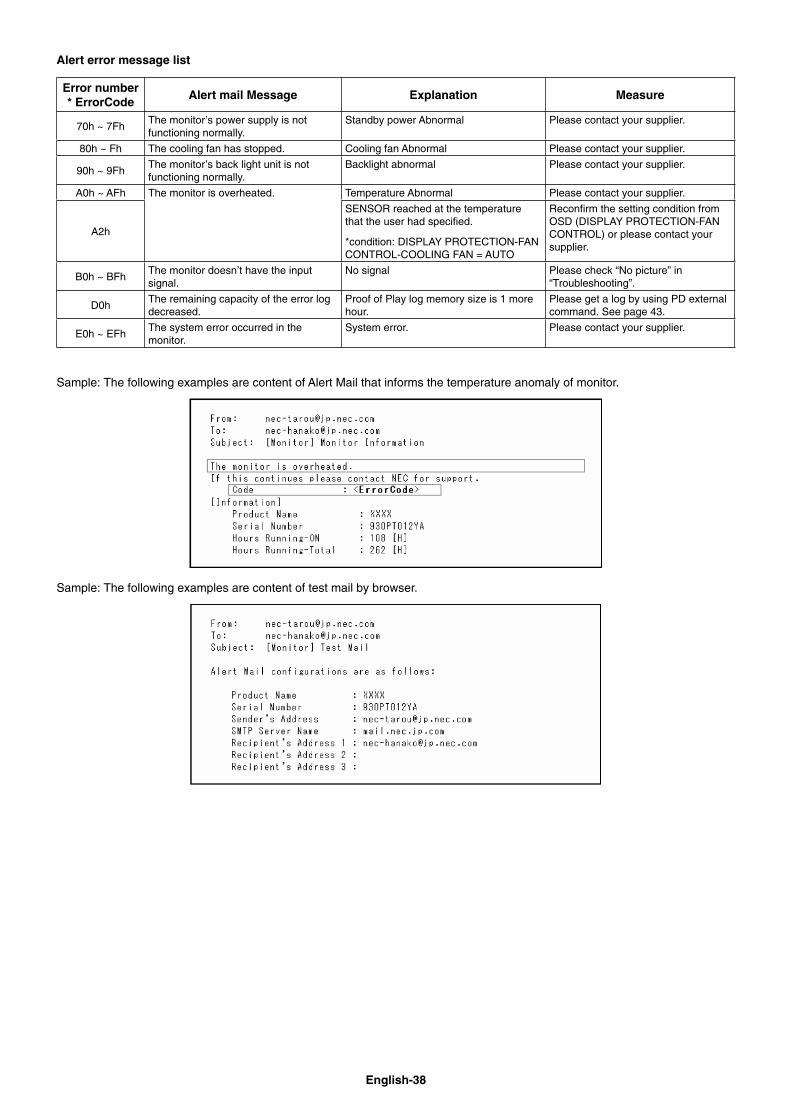
English-38
Alert error message list
Error number* ErrorCode
Alert mail Message Explanation Measure
70h ~ 7Fh The monitor’s power supply is not functioning normally.
Standby power Abnormal Please contact your supplier.
80h ~ Fh The cooling fan has stopped. Cooling fan Abnormal Please contact your supplier.
90h ~ 9Fh The monitor’s back light unit is not functioning normally.
Backlight abnormal Please contact your supplier.
A0h ~ AFh The monitor is overheated. Temperature Abnormal Please contact your supplier.
A2h
SENSOR reached at the temperature that the user had specifi ed.
*condition: DISPLAY PROTECTION-FAN CONTROL-COOLING FAN = AUTO
Reconfi rm the setting condition from OSD (DISPLAY PROTECTION-FAN CONTROL) or please contact your supplier.
B0h ~ BFh The monitor doesn’t have the input signal.
No signal Please check “No picture” in “Troubleshooting”.
D0hThe remaining capacity of the error log decreased.
Proof of Play log memory size is 1 more hour.
Please get a log by using PD external command. See page 43.
E0h ~ EFhThe system error occurred in the monitor.
System error. Please contact your supplier.
Sample: The following examples are content of Alert Mail that informs the temperature anomaly of monitor.
Sample: The following examples are content of test mail by browser.
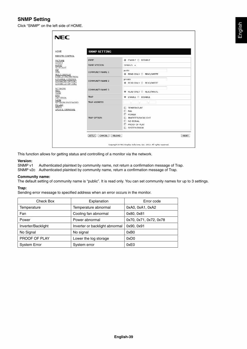
English-39
Eng
lish
SNMP SettingClick “SNMP” on the left side of HOME.
This function allows for getting status and controlling of a monitor via the network.
Version:SNMP v1 Authenticated plaintext by community name, not return a confi rmation message of Trap.SNMP v2c Authenticated plaintext by community name, return a confi rmation message of Trap.
Community name:The default setting of community name is “public”. It is read only. You can set community names for up to 3 settings.
Trap:Sending error message to specifi ed address when an error occurs in the monitor.
Check Box Explanation Error code
Temperature Temperature abnormal 0xA0, 0xA1, 0xA2
Fan Cooling fan abnormal 0x80, 0x81
Power Power abnormal 0x70, 0x71, 0x72, 0x78
Inverter/Backlight Inverter or backlight abnormal 0x90, 0x91
No Signal No signal 0xB0
PROOF OF PLAY Lower the log storage 0xD0
System Error System error 0xE0
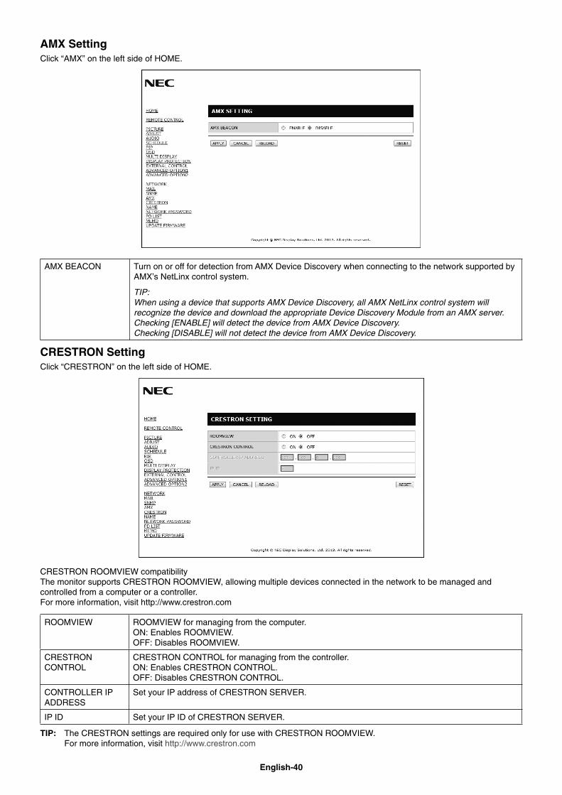
English-40
AMX SettingClick “AMX” on the left side of HOME.
AMX BEACON Turn on or off for detection from AMX Device Discovery when connecting to the network supported by AMX’s NetLinx control system.
TIP: When using a device that supports AMX Device Discovery, all AMX NetLinx control system will recognize the device and download the appropriate Device Discovery Module from an AMX server.Checking [ENABLE] will detect the device from AMX Device Discovery.Checking [DISABLE] will not detect the device from AMX Device Discovery.
CRESTRON SettingClick “CRESTRON” on the left side of HOME.
CRESTRON ROOMVIEW compatibilityThe monitor supports CRESTRON ROOMVIEW, allowing multiple devices connected in the network to be managed and controlled from a computer or a controller.For more information, visit http://www.crestron.com
ROOMVIEW ROOMVIEW for managing from the computer.ON: Enables ROOMVIEW. OFF: Disables ROOMVIEW.
CRESTRON CONTROL
CRESTRON CONTROL for managing from the controller.ON: Enables CRESTRON CONTROL. OFF: Disables CRESTRON CONTROL.
CONTROLLER IP ADDRESS
Set your IP address of CRESTRON SERVER.
IP ID Set your IP ID of CRESTRON SERVER.
TIP: The CRESTRON settings are required only for use with CRESTRON ROOMVIEW.For more information, visit http://www.crestron.com
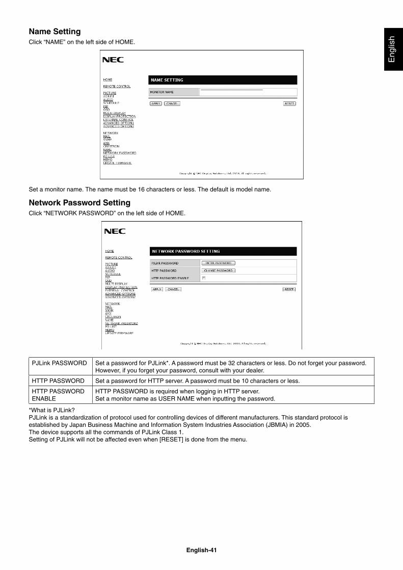
English-41
Eng
lish
Name SettingClick “NAME” on the left side of HOME.
Set a monitor name. The name must be 16 characters or less. The default is model name.
Network Password SettingClick “NETWORK PASSWORD” on the left side of HOME.
PJLink PASSWORD Set a password for PJLink*. A password must be 32 characters or less. Do not forget your password. However, if you forget your password, consult with your dealer.
HTTP PASSWORD Set a password for HTTP server. A password must be 10 characters or less.
HTTP PASSWORDENABLE
HTTP PASSWORD is required when logging in HTTP server.Set a monitor name as USER NAME when inputting the password.
*What is PJLink?PJLink is a standardization of protocol used for controlling devices of different manufacturers. This standard protocol is established by Japan Business Machine and Information System Industries Association (JBMIA) in 2005.The device supports all the commands of PJLink Class 1.Setting of PJLink will not be affected even when [RESET] is done from the menu.
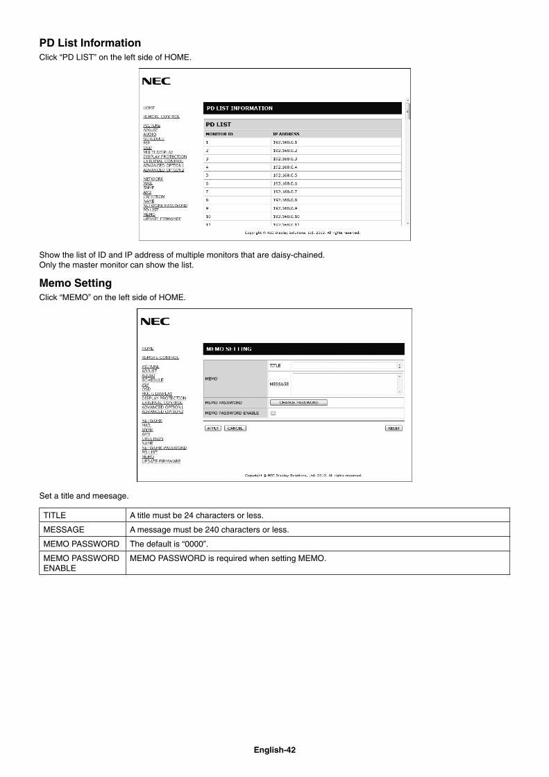
English-42
PD List InformationClick “PD LIST” on the left side of HOME.
Show the list of ID and IP address of multiple monitors that are daisy-chained.Only the master monitor can show the list.
Memo SettingClick “MEMO” on the left side of HOME.
Set a title and meesage.
TITLE A title must be 24 characters or less.
MESSAGE A message must be 240 characters or less.
MEMO PASSWORD The default is “0000”.
MEMO PASSWORD ENABLE
MEMO PASSWORD is required when setting MEMO.
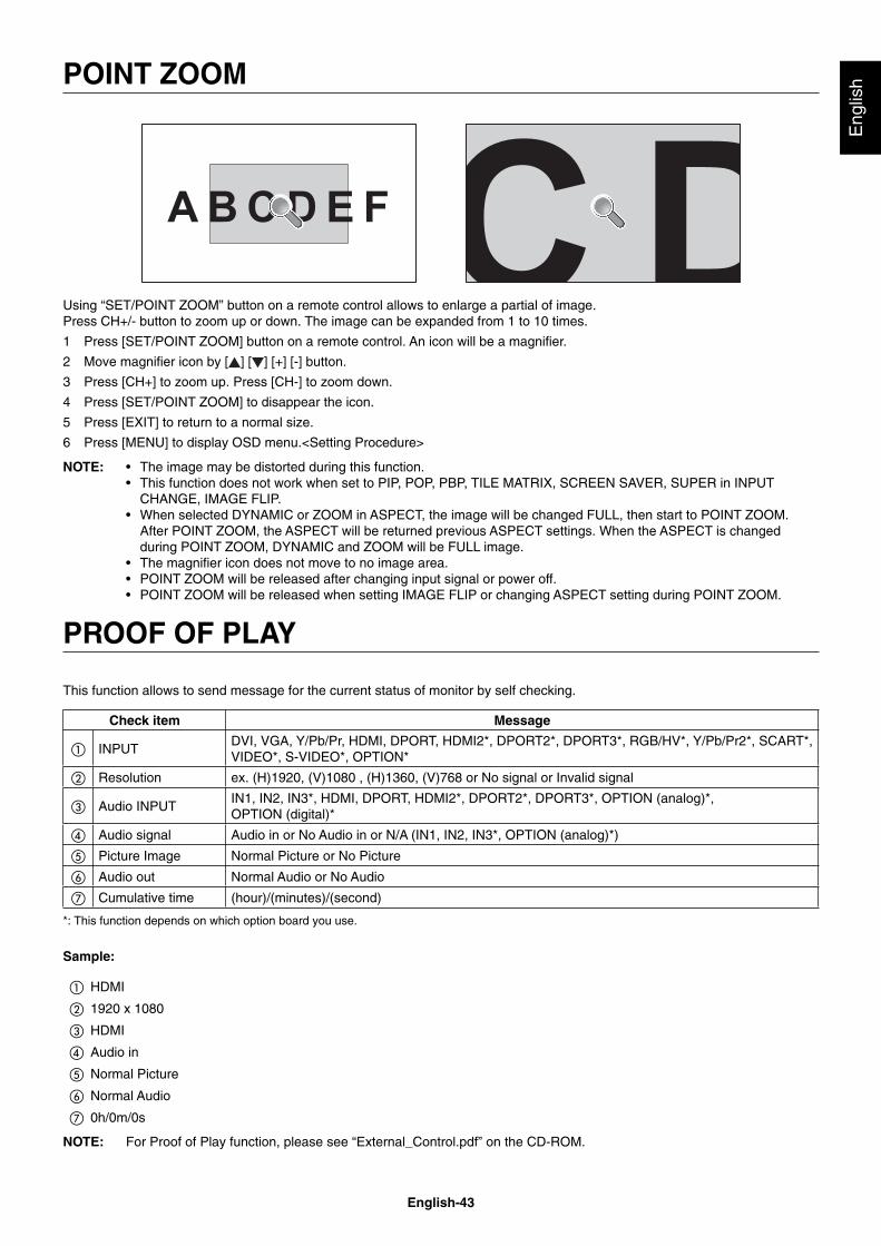
English-43
Eng
lish
Using “SET/POINT ZOOM” button on a remote control allows to enlarge a partial of image.Press CH+/- button to zoom up or down. The image can be expanded from 1 to 10 times.
1 Press [SET/POINT ZOOM] button on a remote control. An icon will be a magnifi er.
2 Move magnifi er icon by [ ] [ ] [+] [-] button.
3 Press [CH+] to zoom up. Press [CH-] to zoom down.
4 Press [SET/POINT ZOOM] to disappear the icon.
5 Press [EXIT] to return to a normal size.
6 Press [MENU] to display OSD menu.<Setting Procedure>
NOTE: • The image may be distorted during this function.• This function does not work when set to PIP, POP, PBP, TILE MATRIX, SCREEN SAVER, SUPER in INPUT CHANGE, IMAGE FLIP.• When selected DYNAMIC or ZOOM in ASPECT, the image will be changed FULL, then start to POINT ZOOM. After POINT ZOOM, the ASPECT will be returned previous ASPECT settings. When the ASPECT is changed during POINT ZOOM, DYNAMIC and ZOOM will be FULL image.• The magnifi er icon does not move to no image area.• POINT ZOOM will be released after changing input signal or power off.• POINT ZOOM will be released when setting IMAGE FLIP or changing ASPECT setting during POINT ZOOM.
PROOF OF PLAY
This function allows to send message for the current status of monitor by self checking.
Check item Message
① INPUTDVI, VGA, Y/Pb/Pr, HDMI, DPORT, HDMI2*, DPORT2*, DPORT3*, RGB/HV*, Y/Pb/Pr2*, SCART*, VIDEO*, S-VIDEO*, OPTION*
② Resolution ex. (H)1920, (V)1080 , (H)1360, (V)768 or No signal or Invalid signal
③ Audio INPUTIN1, IN2, IN3*, HDMI, DPORT, HDMI2*, DPORT2*, DPORT3*, OPTION (analog)*, OPTION (digital)*
④ Audio signal Audio in or No Audio in or N/A (IN1, IN2, IN3*, OPTION (analog)*)
⑤ Picture Image Normal Picture or No Picture
⑥ Audio out Normal Audio or No Audio
⑦ Cumulative time (hour)/(minutes)/(second)
*: This function depends on which option board you use.
Sample:
① HDMI
② 1920 x 1080
③ HDMI
④ Audio in
⑤ Normal Picture
⑥ Normal Audio
⑦ 0h/0m/0s
NOTE: For Proof of Play function, please see “External_Control.pdf” on the CD-ROM.
POINT ZOOM
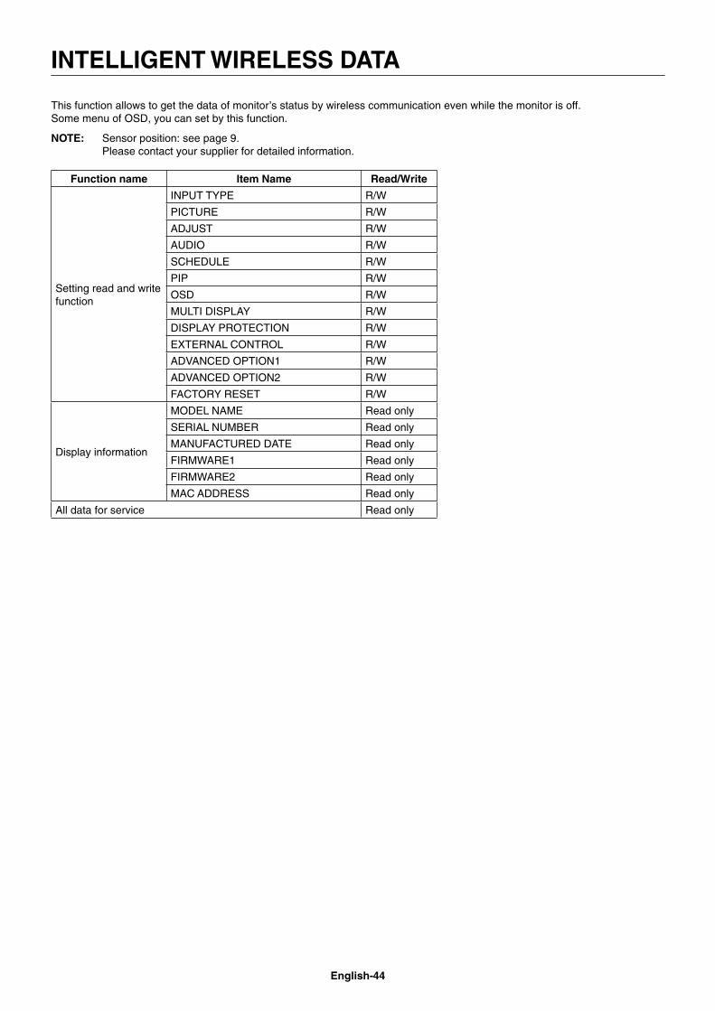
English-44
This function allows to get the data of monitor’s status by wireless communication even while the monitor is off.Some menu of OSD, you can set by this function.
NOTE: Sensor position: see page 9.Please contact your supplier for detailed information.
Function name Item Name Read/Write
Setting read and write function
INPUT TYPE R/W
PICTURE R/W
ADJUST R/W
AUDIO R/W
SCHEDULE R/W
PIP R/W
OSD R/W
MULTI DISPLAY R/W
DISPLAY PROTECTION R/W
EXTERNAL CONTROL R/W
ADVANCED OPTION1 R/W
ADVANCED OPTION2 R/W
FACTORY RESET R/W
Display information
MODEL NAME Read only
SERIAL NUMBER Read only
MANUFACTURED DATE Read only
FIRMWARE1 Read only
FIRMWARE2 Read only
MAC ADDRESS Read only
All data for service Read only
INTELLIGENT WIRELESS DATA
English-45
Eng
lish
Ultra Narrow Bezel: Provides the optimum solution in a tiling environment.
Reduced Footprint: Provides the ideal solution for environments with superior image quality.
Color Control Systems: Allow you to adjust the colors on your screen and customize the color accuracy of your monitor to a variety of standards.
OmniColor: Combines Six-axis color control and the sRGB standard. Six-axis color control permits color adjustments via six axes (R, G, B, C, M and Y) rather than through the three axes (R, G and B) previously available. The sRGB standard provides the monitor with a uniform color profi le. This assures that the colors displayed on the monitor are exactly the same as on the color printout (with sRGB supporting operating system and sRGB printer). This allows you to adjust the colors on your screen and customise the color accuracy of your monitor to a variety of standards.
sRGB Color Control: A new optimized color management standard which allows for color matching on computer displays and other peripherals. The sRGB standard, which is based on a calibrated color space, allows for optimal color representation and backward compatibility with other common color standards.
OSD (On-Screen-Display) Controls: Allow you to quickly and easily adjust all elements of your screen image via simple to use on-screen menus.
Plug and Play: The Microsoft® solution with the Windows® operating system facilitates setup and installation by allowing the monitor to send its capabilities (such as screen size and resolutions supported) directly to your computer, automatically optimizing display performance.
IPM (Intelligent Power Manager) System: Provides innovative power-saving methods that allow the monitor to shift to a lower power consumption level when on but not in use, saving two-thirds of your monitor energy costs, reducing emissions and lowering the air conditioning costs of the workplace.
FullScan Capability: Allows you to use the entire screen area in most resolutions, signifi cantly expanding image size.
VESA Standard (FDMIv1) Mounting Interface: Allows you to connect your LCD monitor to any VESA standard (FDMIv1) third party mounting arm or bracket. NEC recommends using mounting interface that comply with TÜV-GS and/or UL1678 standard in North America.
DVI-D: The digital-only subset of DVI ratifi ed by the Digital Display Working Group (DDWG) for digital connections between computers and displays. As a digital-only connector, analog support is not provided for a DVI-D connector. As a DVI-based digital only connection, only a simple adapter is necessary for compatibility between DVI-D and other DVI-based digital connectors such as DFP and P&D. The DVI interface of this display supports HDCP.
TILE MATRIX, TILE COMP: Shows one image over multiple screens with accuracy while compensating for bezel width.
ZOOM: Expands/reduces image size for horizontal and vertical direction.
Self-diagnosis: If an internal error should occur, a failure state will be indicated.
HDCP (High-bandwidth Digital Content Protection): HDCP is a system for preventing illegal copying of video data sent over a Digital Visual Interface (DVI). If you are unable to view material via the DVI input, this does not necessarily mean the display is not functioning properly. With the implementation of HDCP, there may be cases in which certain content is protected with HDCP and might not be displayed due to the decision/intention of the HDCP community (Digital Content Protection, LLC).
Option board slot: You can use an option board. Please contact your supplier for detailed information.
Features
English-46
No picture• The signal cable should be completely connected to the
display card/computer.
• The display card should be completely seated in its slot.
• Check the main Power Switch, it should be in the ON position.
• Power Switch and computer power switch should be in the ON position.
• Check to make sure that a supported mode has been selected on the display card or system being used. (Please consult display card or system manual to change graphics mode.)
• Check the monitor and your display card with respect to compatibility and recommended settings.
• Check the signal cable connector for bent or pushed-in pins.
• The monitor automatically goes into OFF at the preset time period after signal is lost. Press the power button.
Power Button does not respond• Unplug the power cord of the monitor from the AC outlet to
turn off and reset the monitor.
• Check the main Power Switch on the back side of the monitor.
Image persistence• Please be aware that LCD Technology may experience
a phenomenon known as Image Persistence. Image Persistence occurs when a residual or “ghost” image of a previous image remains visible on the screen. Unlike CRT monitors, LCD monitors’ image persistence is not permanent, but constant images being displayed for a long period of time should be avoided. To alleviate image persistence, turn off the monitor for as long as the previous image was displayed. For example, if an image was on the monitor for one hour and a residual image remains, the monitor should be turned off for one hour to erase the image.
NOTE: As with all personal display devices, NEC DISPLAY SOLUTIONS recommends displaying moving images and using a moving screen saver at regular intervals whenever the screen is idle or turning off the monitor when not in use.
Image is unstable, unfocused or swimming is apparent• Signal cable should be completely attached to the computer.
• Use the OSD Image Adjust controls to focus and adjust display by increasing or decreasing the fi ne adjustment. When the display mode is changed, the OSD Image Adjust settings may need to be re-adjusted.
• Check the monitor and your display card with respect to compatibility and recommended signal timings.
• If your text is garbled, change the video mode to non-interlace and use 60Hz refresh rate.
• The image may be distorted when turning the power on or changing the settings.
Image of component signal is greenish• Check to see if the Y/Pb/Pr input connector is selected.
LED on monitor is not lit (no green or red color can be seen)• Power Switch should be in the ON position and power cord
should be connected.
• Check the main Power Switch, it should be in the ON position.
• Make certain the computer is not in a power-saving mode (touch the keyboard or mouse).
• Check to see that the power indicator option in the OSD is set to ON.
RED LED on monitor is blinking• A certain failure might have occurred, please contact your
nearest authorized NEC DISPLAY SOLUTIONS service facility.
• If the monitor is powered off by the inside temperature being higher than the normal operating temperature, a RED LED will blink six times. Power on the display again after confi rming the inside temperature has been reduced to normal operation temperature.
Display image is not sized properly• Use the OSD Image Adjust controls to increase or decrease
the coarse adjustment.
• Check to make sure that a supported mode has been selected on the display card or system being used. (Please consult display card or system manual to change graphics mode.)
Selected resolution is not displayed properly• Use OSD Display Mode to enter Information menu and
confi rm that the appropriate resolution has been selected. If not, select corresponding option.
No Sound• Check to see if audio cable is properly connected.
• Check to see if mute is activated.
• Check to see if volume is set at minimum.
• Check to see if computer supports an audio signal through DisplayPort.If unsure, contact the computer manufacturer.
• Check to see if SURROUND is ON.
Remote Control is not available• Check the Remote Control’s batteries status.
• Check if batteries are inserted correctly.
• Check if the Remote Control is pointing at the monitor’s remote sensor.
• Check the IR LOCK SETTING status.
• The remote control system may not function when direct sunlight or strong illumination strikes the remote control sensor of the LCD monitor, or when there is an object in the path.
“SCHEDULE”/“OFF TIMER” function is not working properly• The “SCHEDULE” function will be disabled when the “OFF
TIMER” is set.
• If the “OFF TIMER” function is enabled and the power to the LCD monitor is turned off when the power supply is interrupted unexpectedly, then the “OFF TIMER” will be reset.
Snowy Picture, Poor Sound in TV• Check antenna/cable connection. Use new cable if
necessary.
Interference in TV• Check components for shielding, move away from monitor if
necessary.
RS-232C or LAN control is not available• Check RS-232C or LAN cable connection.
Either light vertical or horizontal stripes may appear, depending on the specifi c display pattern. This is no product fault or degradation.
Troubleshooting
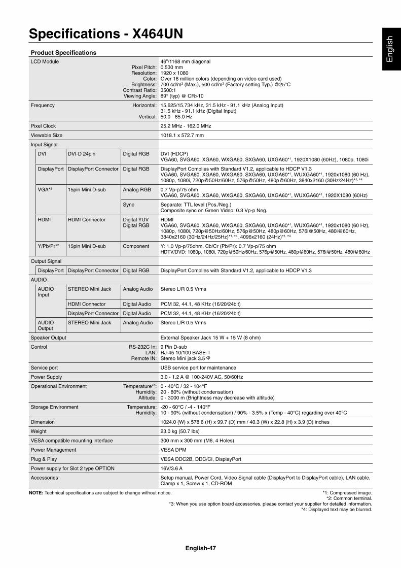
English-47
Eng
lishSpecifi cations - X464UN
Product Specifi cationsLCD Module
Pixel Pitch:Resolution:
Color:Brightness:
Contrast Ratio:Viewing Angle:
46”/1168 mm diagonal0.530 mm1920 x 1080Over 16 million colors (depending on video card used)700 cd/m2 (Max.), 500 cd/m2 (Factory setting Typ.) @25°C3500:189° (typ) @ CR>10
Frequency Horizontal:
Vertical:
15.625/15.734 kHz, 31.5 kHz - 91.1 kHz (Analog Input)31.5 kHz - 91.1 kHz (Digital Input)50.0 - 85.0 Hz
Pixel Clock 25.2 MHz - 162.0 MHz
Viewable Size 1018.1 x 572.7 mm
Input Signal
DVI DVI-D 24pin Digital RGB DVI (HDCP)VGA60, SVGA60, XGA60, WXGA60, SXGA60, UXGA60*1, 1920X1080 (60Hz), 1080p, 1080i
DisplayPort DisplayPort Connector Digital RGB DisplayPort Complies with Standard V1.2, applicable to HDCP V1.3VGA60, SVGA60, XGA60, WXGA60, SXGA60, UXGA60*1, WUXGA60*1, 1920x1080 (60 Hz), 1080p, 1080i, 720p@50Hz/60Hz, 576p@50Hz, 480p@60Hz, 3840x2160 (30Hz/24Hz)*1, *4
VGA*2 15pin Mini D-sub Analog RGB 0.7 Vp-p/75 ohmVGA60, SVGA60, XGA60, WXGA60, SXGA60, UXGA60*1, WUXGA60*1, 1920X1080 (60Hz)
Sync Separate: TTL level (Pos./Neg.)Composite sync on Green Video: 0.3 Vp-p Neg.
HDMI HDMI Connector Digital YUVDigital RGB
HDMIVGA60, SVGA60, XGA60, WXGA60, SXGA60, UXGA60*1, WUXGA60*1, 1920x1080 (60 Hz), 1080p, 1080i, 720p@50Hz/60Hz, 576p@50Hz, 480p@60Hz, 576i@50Hz, 480i@60Hz, 3840x2160 (30Hz/24Hz/25Hz)*1, *4, 4096x2160 (24Hz)*1, *4
Y/Pb/Pr*2 15pin Mini D-sub Component Y: 1.0 Vp-p/75ohm, Cb/Cr (Pb/Pr): 0.7 Vp-p/75 ohmHDTV/DVD: 1080p, 1080i, 720p@50Hz/60Hz, 576p@50Hz, 480p@60Hz, 576i@50Hz, 480i@60Hz
Output Signal
DisplayPort DisplayPort Connector Digital RGB DisplayPort Complies with Standard V1.2, applicable to HDCP V1.3
AUDIO
AUDIO Input
STEREO Mini Jack Analog Audio Stereo L/R 0.5 Vrms
HDMI Connector Digital Audio PCM 32, 44.1, 48 KHz (16/20/24bit)
DisplayPort Connector Digital Audio PCM 32, 44.1, 48 KHz (16/20/24bit)
AUDIO Output
STEREO Mini Jack Analog Audio Stereo L/R 0.5 Vrms
Speaker Output External Speaker Jack 15 W + 15 W (8 ohm)
Control RS-232C In:LAN:
Remote IN:
9 Pin D-subRJ-45 10/100 BASE-TStereo Mini jack 3.5
Service port USB service port for maintenance
Power Supply 3.0 - 1.2 A @ 100-240V AC, 50/60Hz
Operational Environment Temperature*3:Humidity:Altitude:
0 - 40°C / 32 - 104°F20 - 80% (without condensation)0 - 3000 m (Brightness may decrease with altitude)
Storage Environment Temperature:Humidity:
-20 - 60°C / -4 - 140°F10 - 90% (without condensation) / 90% - 3.5% x (Temp - 40°C) regarding over 40°C
Dimension 1024.0 (W) x 578.6 (H) x 99.7 (D) mm / 40.3 (W) x 22.8 (H) x 3.9 (D) inches
Weight 23.0 kg (50.7 lbs)
VESA compatible mounting interface 300 mm x 300 mm (M6, 4 Holes)
Power Management VESA DPM
Plug & Play VESA DDC2B, DDC/CI, DisplayPort
Power supply for Slot 2 type OPTION 16V/3.6 A
Accessories Setup manual, Power Cord, Video Signal cable (DisplayPort to DisplayPort cable), LAN cable, Clamp x 1, Screw x 1, CD-ROM
NOTE: Technical specifi cations are subject to change without notice. *1: Compressed image. *2: Common terminal. *3: When you use option board accessories, please contact your supplier for detailed information. *4: Displayed text may be blurred.
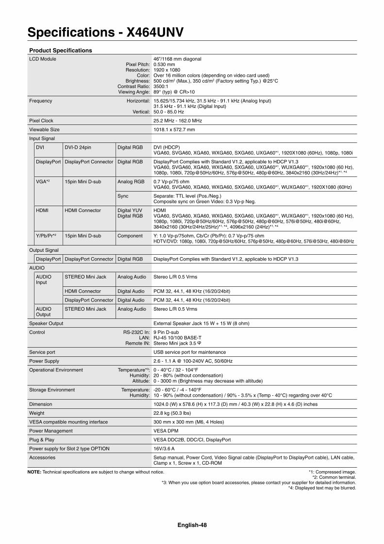
English-48
Specifi cations - X464UNVProduct Specifi cationsLCD Module
Pixel Pitch:Resolution:
Color:Brightness:
Contrast Ratio:Viewing Angle:
46”/1168 mm diagonal0.530 mm1920 x 1080Over 16 million colors (depending on video card used)500 cd/m2 (Max.), 350 cd/m2 (Factory setting Typ.) @25°C3500:189° (typ) @ CR>10
Frequency Horizontal:
Vertical:
15.625/15.734 kHz, 31.5 kHz - 91.1 kHz (Analog Input)31.5 kHz - 91.1 kHz (Digital Input)50.0 - 85.0 Hz
Pixel Clock 25.2 MHz - 162.0 MHz
Viewable Size 1018.1 x 572.7 mm
Input Signal
DVI DVI-D 24pin Digital RGB DVI (HDCP)VGA60, SVGA60, XGA60, WXGA60, SXGA60, UXGA60*1, 1920X1080 (60Hz), 1080p, 1080i
DisplayPort DisplayPort Connector Digital RGB DisplayPort Complies with Standard V1.2, applicable to HDCP V1.3VGA60, SVGA60, XGA60, WXGA60, SXGA60, UXGA60*1, WUXGA60*1, 1920x1080 (60 Hz), 1080p, 1080i, 720p@50Hz/60Hz, 576p@50Hz, 480p@60Hz, 3840x2160 (30Hz/24Hz)*1, *4
VGA*2 15pin Mini D-sub Analog RGB 0.7 Vp-p/75 ohmVGA60, SVGA60, XGA60, WXGA60, SXGA60, UXGA60*1, WUXGA60*1, 1920X1080 (60Hz)
Sync Separate: TTL level (Pos./Neg.)Composite sync on Green Video: 0.3 Vp-p Neg.
HDMI HDMI Connector Digital YUVDigital RGB
HDMIVGA60, SVGA60, XGA60, WXGA60, SXGA60, UXGA60*1, WUXGA60*1, 1920x1080 (60 Hz), 1080p, 1080i, 720p@50Hz/60Hz, 576p@50Hz, 480p@60Hz, 576i@50Hz, 480i@60Hz, 3840x2160 (30Hz/24Hz/25Hz)*1, *4, 4096x2160 (24Hz)*1, *4
Y/Pb/Pr*2 15pin Mini D-sub Component Y: 1.0 Vp-p/75ohm, Cb/Cr (Pb/Pr): 0.7 Vp-p/75 ohmHDTV/DVD: 1080p, 1080i, 720p@50Hz/60Hz, 576p@50Hz, 480p@60Hz, 576i@50Hz, 480i@60Hz
Output Signal
DisplayPort DisplayPort Connector Digital RGB DisplayPort Complies with Standard V1.2, applicable to HDCP V1.3
AUDIO
AUDIO Input
STEREO Mini Jack Analog Audio Stereo L/R 0.5 Vrms
HDMI Connector Digital Audio PCM 32, 44.1, 48 KHz (16/20/24bit)
DisplayPort Connector Digital Audio PCM 32, 44.1, 48 KHz (16/20/24bit)
AUDIO Output
STEREO Mini Jack Analog Audio Stereo L/R 0.5 Vrms
Speaker Output External Speaker Jack 15 W + 15 W (8 ohm)
Control RS-232C In:LAN:
Remote IN:
9 Pin D-subRJ-45 10/100 BASE-TStereo Mini jack 3.5
Service port USB service port for maintenance
Power Supply 2.6 - 1.1 A @ 100-240V AC, 50/60Hz
Operational Environment Temperature*3:Humidity:Altitude:
0 - 40°C / 32 - 104°F20 - 80% (without condensation)0 - 3000 m (Brightness may decrease with altitude)
Storage Environment Temperature:Humidity:
-20 - 60°C / -4 - 140°F10 - 90% (without condensation) / 90% - 3.5% x (Temp - 40°C) regarding over 40°C
Dimension 1024.0 (W) x 578.6 (H) x 117.3 (D) mm / 40.3 (W) x 22.8 (H) x 4.6 (D) inches
Weight 22.8 kg (50.3 lbs)
VESA compatible mounting interface 300 mm x 300 mm (M6, 4 Holes)
Power Management VESA DPM
Plug & Play VESA DDC2B, DDC/CI, DisplayPort
Power supply for Slot 2 type OPTION 16V/3.6 A
Accessories Setup manual, Power Cord, Video Signal cable (DisplayPort to DisplayPort cable), LAN cable, Clamp x 1, Screw x 1, CD-ROM
NOTE: Technical specifi cations are subject to change without notice. *1: Compressed image. *2: Common terminal. *3: When you use option board accessories, please contact your supplier for detailed information. *4: Displayed text may be blurred.
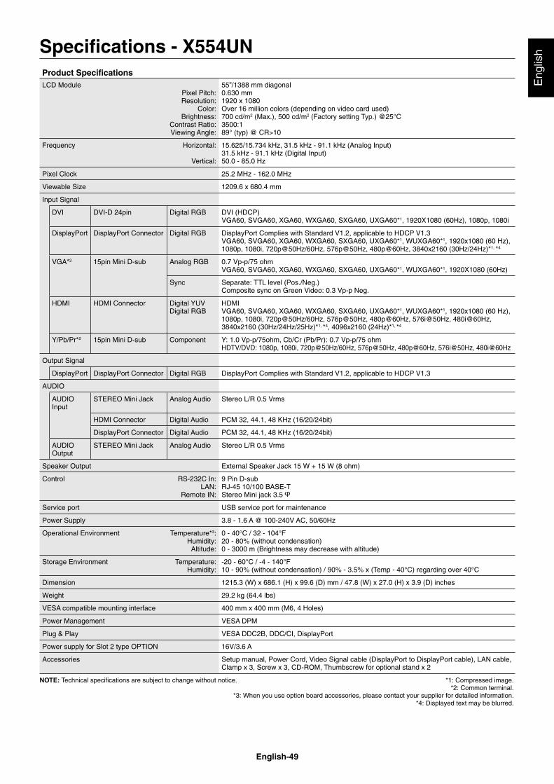
English-49
Eng
lishSpecifi cations - X554UN
Product Specifi cationsLCD Module
Pixel Pitch:Resolution:
Color:Brightness:
Contrast Ratio:Viewing Angle:
55”/1388 mm diagonal0.630 mm1920 x 1080Over 16 million colors (depending on video card used)700 cd/m2 (Max.), 500 cd/m2 (Factory setting Typ.) @25°C3500:189° (typ) @ CR>10
Frequency Horizontal:
Vertical:
15.625/15.734 kHz, 31.5 kHz - 91.1 kHz (Analog Input)31.5 kHz - 91.1 kHz (Digital Input)50.0 - 85.0 Hz
Pixel Clock 25.2 MHz - 162.0 MHz
Viewable Size 1209.6 x 680.4 mm
Input Signal
DVI DVI-D 24pin Digital RGB DVI (HDCP)VGA60, SVGA60, XGA60, WXGA60, SXGA60, UXGA60*1, 1920X1080 (60Hz), 1080p, 1080i
DisplayPort DisplayPort Connector Digital RGB DisplayPort Complies with Standard V1.2, applicable to HDCP V1.3VGA60, SVGA60, XGA60, WXGA60, SXGA60, UXGA60*1, WUXGA60*1, 1920x1080 (60 Hz), 1080p, 1080i, 720p@50Hz/60Hz, 576p@50Hz, 480p@60Hz, 3840x2160 (30Hz/24Hz)*1, *4
VGA*2 15pin Mini D-sub Analog RGB 0.7 Vp-p/75 ohmVGA60, SVGA60, XGA60, WXGA60, SXGA60, UXGA60*1, WUXGA60*1, 1920X1080 (60Hz)
Sync Separate: TTL level (Pos./Neg.)Composite sync on Green Video: 0.3 Vp-p Neg.
HDMI HDMI Connector Digital YUVDigital RGB
HDMIVGA60, SVGA60, XGA60, WXGA60, SXGA60, UXGA60*1, WUXGA60*1, 1920x1080 (60 Hz), 1080p, 1080i, 720p@50Hz/60Hz, 576p@50Hz, 480p@60Hz, 576i@50Hz, 480i@60Hz, 3840x2160 (30Hz/24Hz/25Hz)*1, *4, 4096x2160 (24Hz)*1, *4
Y/Pb/Pr*2 15pin Mini D-sub Component Y: 1.0 Vp-p/75ohm, Cb/Cr (Pb/Pr): 0.7 Vp-p/75 ohmHDTV/DVD: 1080p, 1080i, 720p@50Hz/60Hz, 576p@50Hz, 480p@60Hz, 576i@50Hz, 480i@60Hz
Output Signal
DisplayPort DisplayPort Connector Digital RGB DisplayPort Complies with Standard V1.2, applicable to HDCP V1.3
AUDIO
AUDIO Input
STEREO Mini Jack Analog Audio Stereo L/R 0.5 Vrms
HDMI Connector Digital Audio PCM 32, 44.1, 48 KHz (16/20/24bit)
DisplayPort Connector Digital Audio PCM 32, 44.1, 48 KHz (16/20/24bit)
AUDIO Output
STEREO Mini Jack Analog Audio Stereo L/R 0.5 Vrms
Speaker Output External Speaker Jack 15 W + 15 W (8 ohm)
Control RS-232C In:LAN:
Remote IN:
9 Pin D-subRJ-45 10/100 BASE-TStereo Mini jack 3.5
Service port USB service port for maintenance
Power Supply 3.8 - 1.6 A @ 100-240V AC, 50/60Hz
Operational Environment Temperature*3:Humidity:Altitude:
0 - 40°C / 32 - 104°F20 - 80% (without condensation)0 - 3000 m (Brightness may decrease with altitude)
Storage Environment Temperature:Humidity:
-20 - 60°C / -4 - 140°F10 - 90% (without condensation) / 90% - 3.5% x (Temp - 40°C) regarding over 40°C
Dimension 1215.3 (W) x 686.1 (H) x 99.6 (D) mm / 47.8 (W) x 27.0 (H) x 3.9 (D) inches
Weight 29.2 kg (64.4 lbs)
VESA compatible mounting interface 400 mm x 400 mm (M6, 4 Holes)
Power Management VESA DPM
Plug & Play VESA DDC2B, DDC/CI, DisplayPort
Power supply for Slot 2 type OPTION 16V/3.6 A
Accessories Setup manual, Power Cord, Video Signal cable (DisplayPort to DisplayPort cable), LAN cable, Clamp x 3, Screw x 3, CD-ROM, Thumbscrew for optional stand x 2
NOTE: Technical specifi cations are subject to change without notice. *1: Compressed image. *2: Common terminal. *3: When you use option board accessories, please contact your supplier for detailed information. *4: Displayed text may be blurred.
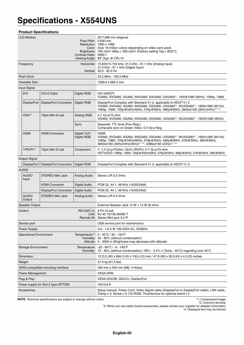
English-50
Specifi cations - X554UNSProduct Specifi cationsLCD Module
Pixel Pitch:Resolution:
Color:Brightness:
Contrast Ratio:Viewing Angle:
55”/1388 mm diagonal0.630 mm1920 x 1080Over 16 million colors (depending on video card used)700 cd/m2 (Max.), 500 cd/m2 (Factory setting Typ.) @25°C3500:189° (typ) @ CR>10
Frequency Horizontal:
Vertical:
15.625/15.734 kHz, 31.5 kHz - 91.1 kHz (Analog Input)31.5 kHz - 91.1 kHz (Digital Input)50.0 - 85.0 Hz
Pixel Clock 25.2 MHz - 162.0 MHz
Viewable Size 1209.6 x 680.4 mm
Input Signal
DVI DVI-D 24pin Digital RGB DVI (HDCP)VGA60, SVGA60, XGA60, WXGA60, SXGA60, UXGA60*1, 1920X1080 (60Hz), 1080p, 1080i
DisplayPort DisplayPort Connector Digital RGB DisplayPort Complies with Standard V1.2, applicable to HDCP V1.3VGA60, SVGA60, XGA60, WXGA60, SXGA60, UXGA60*1, WUXGA60*1, 1920x1080 (60 Hz), 1080p, 1080i, 720p@50Hz/60Hz, 576p@50Hz, 480p@60Hz, 3840x2160 (30Hz/24Hz)*1, *4
VGA*2 15pin Mini D-sub Analog RGB 0.7 Vp-p/75 ohmVGA60, SVGA60, XGA60, WXGA60, SXGA60, UXGA60*1, WUXGA60*1, 1920X1080 (60Hz)
Sync Separate: TTL level (Pos./Neg.)Composite sync on Green Video: 0.3 Vp-p Neg.
HDMI HDMI Connector Digital YUVDigital RGB
HDMIVGA60, SVGA60, XGA60, WXGA60, SXGA60, UXGA60*1, WUXGA60*1, 1920x1080 (60 Hz), 1080p, 1080i, 720p@50Hz/60Hz, 576p@50Hz, 480p@60Hz, 576i@50Hz, 480i@60Hz, 3840x2160 (30Hz/24Hz/25Hz)*1, *4, 4096x2160 (24Hz)*1, *4
Y/Pb/Pr*2 15pin Mini D-sub Component Y: 1.0 Vp-p/75ohm, Cb/Cr (Pb/Pr): 0.7 Vp-p/75 ohmHDTV/DVD: 1080p, 1080i, 720p@50Hz/60Hz, 576p@50Hz, 480p@60Hz, 576i@50Hz, 480i@60Hz
Output Signal
DisplayPort DisplayPort Connector Digital RGB DisplayPort Complies with Standard V1.2, applicable to HDCP V1.3
AUDIO
AUDIO Input
STEREO Mini Jack Analog Audio Stereo L/R 0.5 Vrms
HDMI Connector Digital Audio PCM 32, 44.1, 48 KHz (16/20/24bit)
DisplayPort Connector Digital Audio PCM 32, 44.1, 48 KHz (16/20/24bit)
AUDIO Output
STEREO Mini Jack Analog Audio Stereo L/R 0.5 Vrms
Speaker Output External Speaker Jack 15 W + 15 W (8 ohm)
Control RS-232C In:LAN:
Remote IN:
9 Pin D-subRJ-45 10/100 BASE-TStereo Mini jack 3.5
Service port USB service port for maintenance
Power Supply 3.8 - 1.6 A @ 100-240V AC, 50/60Hz
Operational Environment Temperature*3:Humidity:Altitude:
0 - 40°C / 32 - 104°F20 - 80% (without condensation)0 - 3000 m (Brightness may decrease with altitude)
Storage Environment Temperature:Humidity:
-20 - 60°C / -4 - 140°F10 - 90% (without condensation) / 90% - 3.5% x (Temp - 40°C) regarding over 40°C
Dimension 1213.5 (W) x 684.3 (H) x 100.4 (D) mm / 47.8 (W) x 26.9 (H) x 4.0 (D) inches
Weight 27.9 kg (61.5 lbs)
VESA compatible mounting interface 400 mm x 400 mm (M6, 4 Holes)
Power Management VESA DPM
Plug & Play VESA DDC2B, DDC/CI, DisplayPort
Power supply for Slot 2 type OPTION 16V/3.6 A
Accessories Setup manual, Power Cord, Video Signal cable (DisplayPort to DisplayPort cable), LAN cable, Clamp x 3, Screw x 3, CD-ROM, Thumbscrew for optional stand x 2
NOTE: Technical specifi cations are subject to change without notice. *1: Compressed image. *2: Common terminal. *3: When you use option board accessories, please contact your supplier for detailed information. *4: Displayed text may be blurred.
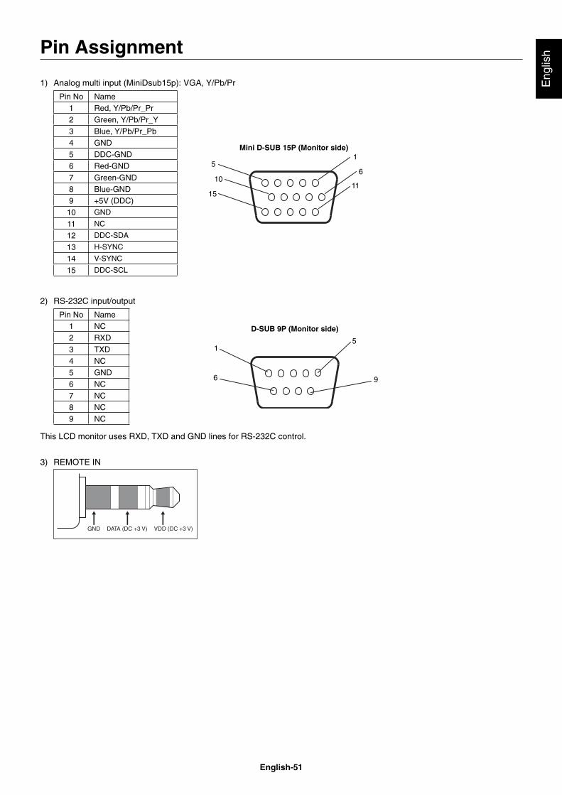
English-51
Eng
lish
1) Analog multi input (MiniDsub15p): VGA, Y/Pb/Pr
Pin No Name1 Red, Y/Pb/Pr_Pr2 Green, Y/Pb/Pr_Y3 Blue, Y/Pb/Pr_Pb4 GND5 DDC-GND6 Red-GND7 Green-GND8 Blue-GND9 +5V (DDC)10 GND
11 NC
12 DDC-SDA
13 H-SYNC
14 V-SYNC
15 DDC-SCL
5
10
15
1
6
11
Mini D-SUB 15P (Monitor side)
2) RS-232C input/output
1
6
5
9
D-SUB 9P (Monitor side)
Pin No Name1 NC2 RXD3 TXD4 NC5 GND6 NC7 NC8 NC9 NC
This LCD monitor uses RXD, TXD and GND lines for RS-232C control.
3) REMOTE IN
Pin Assignment
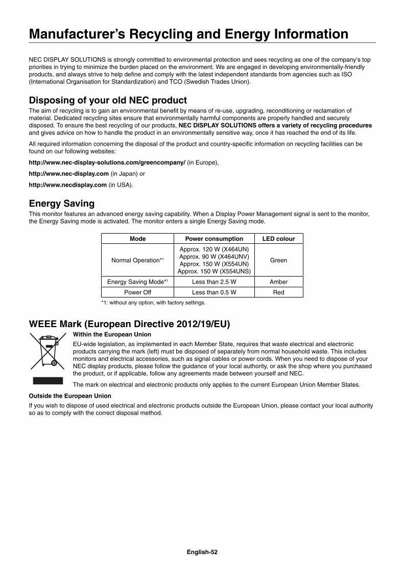
English-52
NEC DISPLAY SOLUTIONS is strongly committed to environmental protection and sees recycling as one of the company’s top priorities in trying to minimize the burden placed on the environment. We are engaged in developing environmentally-friendly products, and always strive to help defi ne and comply with the latest independent standards from agencies such as ISO (International Organisation for Standardization) and TCO (Swedish Trades Union).
Disposing of your old NEC productThe aim of recycling is to gain an environmental benefi t by means of re-use, upgrading, reconditioning or reclamation of material. Dedicated recycling sites ensure that environmentally harmful components are properly handled and securely disposed. To ensure the best recycling of our products, NEC DISPLAY SOLUTIONS offers a variety of recycling procedures and gives advice on how to handle the product in an environmentally sensitive way, once it has reached the end of its life.
All required information concerning the disposal of the product and country-specifi c information on recycling facilities can be found on our following websites:
http://www.nec-display-solutions.com/greencompany/ (in Europe),
http://www.nec-display.com (in Japan) or
http://www.necdisplay.com (in USA).
Energy SavingThis monitor features an advanced energy saving capability. When a Display Power Management signal is sent to the monitor, the Energy Saving mode is activated. The monitor enters a single Energy Saving mode.
Mode Power consumption LED colour
Normal Operation*1
Approx. 120 W (X464UN)Approx. 90 W (X464UNV)Approx. 150 W (X554UN)
Approx. 150 W (X554UNS)
Green
Energy Saving Mode*1 Less than 2.5 W Amber
Power Off Less than 0.5 W Red
*1: without any option, with factory settings.
WEEE Mark (European Directive 2012/19/EU)Within the European Union
EU-wide legislation, as implemented in each Member State, requires that waste electrical and electronic products carrying the mark (left) must be disposed of separately from normal household waste. This includes monitors and electrical accessories, such as signal cables or power cords. When you need to dispose of your NEC display products, please follow the guidance of your local authority, or ask the shop where you purchased the product, or if applicable, follow any agreements made between yourself and NEC.
The mark on electrical and electronic products only applies to the current European Union Member States.
Outside the European Union
If you wish to dispose of used electrical and electronic products outside the European Union, please contact your local authority so as to comply with the correct disposal method.
Manufacturer’s Recycling and Energy Information