Embed Size (px)
Citation preview
FRICTION
Prepared By:
Kumar Ankur
Introduction
• Friction is the resistance to motion during sliding or rolling, that is
experienced when one solid body moves tangentially over another with
which it is in contact.
• The resistive tangential force, which acts in a direction directly opposite to
the direction of motion, is called the friction force.
• There are two main types of friction that are commonly encountered: dry
friction and fluid friction.
• As its name suggests, dry friction, also called “Coulomb” friction,
describes the tangential component of the contact force that exists when
two dry surfaces move or tend to move relative to one another.
• Fluid friction describes the tangential component of the contact force that
exists between adjacent layers in a fluid that are moving at different
velocities relative to each other as in a liquid or gas between bearing
surfaces.

Figure 1. Schematic illustrations of (a) a body sliding on a surface with a free body diagram, and(b) a body rolling on a horizontal surface; W is the normal load (force) and F is the friction force.
This chapter includes various mechanisms of friction in solid-solid and liquid-mediated contacts followed by representative data of friction of materials.
Solid–Solid ContactRules of Sliding Friction• Two basic rules of intrinsic (or conventional) friction are generally obeyed
over a wide range of applications.• These rules are often referred to as Amontons equations, after the French
physicist Guillaume Amontons who rediscovered them in 1699.• The first rule states that the friction force, F, is directly proportional to the
nominal load, W, that is, F = μ W.• where μ is a proportionality constant known as the coefficient of static friction
(μs ) or kinetic friction (μk ) which is independent of the normal load.• It is often convenient to express this rule in terms of constant angle of repose
or frictional angle θ defined by, μs = tanθ• In this equation, θ is the angle such that any body of any weight, placed on a
plane inclined at an angle less than θ from the horizontal, will remainstationary, but if the inclination angle is increased to θ, the body will start toslide down in figure 2.
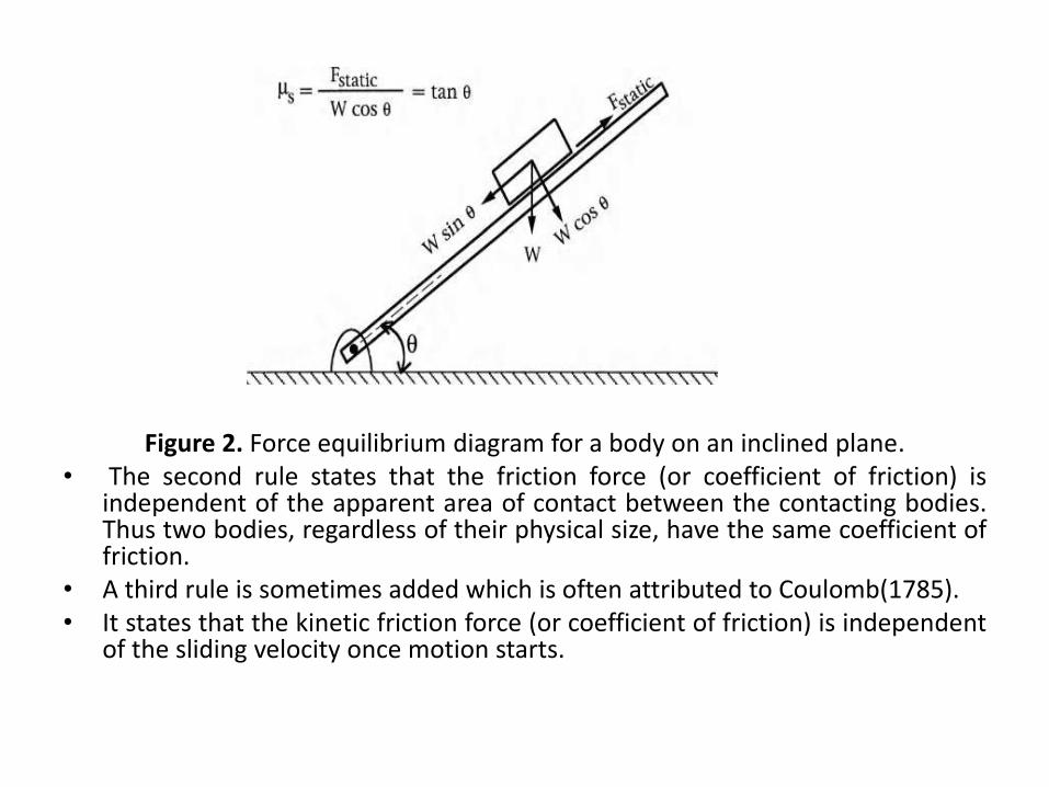
Figure 2. Force equilibrium diagram for a body on an inclined plane.• The second rule states that the friction force (or coefficient of friction) is
independent of the apparent area of contact between the contacting bodies.Thus two bodies, regardless of their physical size, have the same coefficient offriction.
• A third rule is sometimes added which is often attributed to Coulomb(1785).• It states that the kinetic friction force (or coefficient of friction) is independent
of the sliding velocity once motion starts.
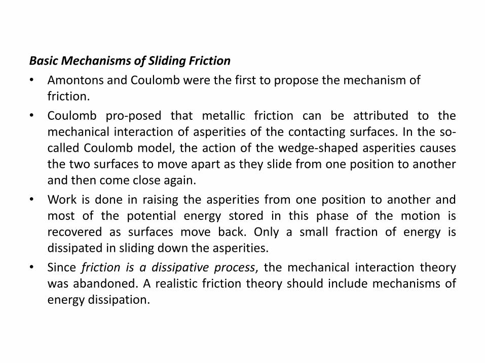
Basic Mechanisms of Sliding Friction
• Amontons and Coulomb were the first to propose the mechanism of friction.
• Coulomb pro-posed that metallic friction can be attributed to themechanical interaction of asperities of the contacting surfaces. In the so-called Coulomb model, the action of the wedge-shaped asperities causesthe two surfaces to move apart as they slide from one position to anotherand then come close again.
• Work is done in raising the asperities from one position to another andmost of the potential energy stored in this phase of the motion isrecovered as surfaces move back. Only a small fraction of energy isdissipated in sliding down the asperities.
• Since friction is a dissipative process, the mechanical interaction theorywas abandoned. A realistic friction theory should include mechanisms ofenergy dissipation.
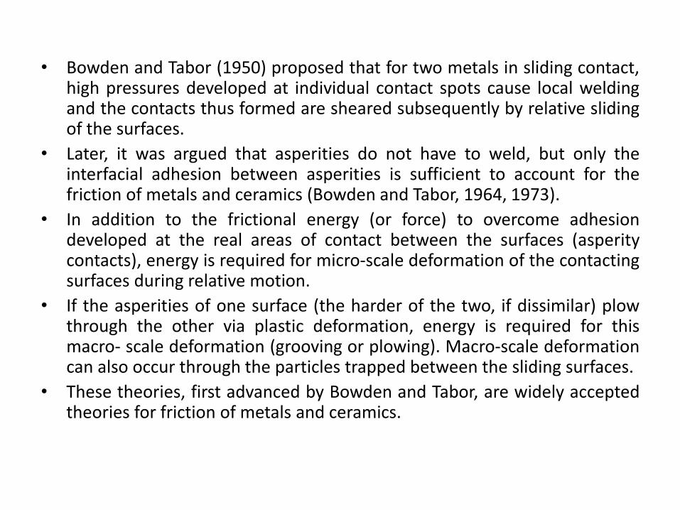
• Bowden and Tabor (1950) proposed that for two metals in sliding contact,high pressures developed at individual contact spots cause local weldingand the contacts thus formed are sheared subsequently by relative slidingof the surfaces.
• Later, it was argued that asperities do not have to weld, but only theinterfacial adhesion between asperities is sufficient to account for thefriction of metals and ceramics (Bowden and Tabor, 1964, 1973).
• In addition to the frictional energy (or force) to overcome adhesiondeveloped at the real areas of contact between the surfaces (asperitycontacts), energy is required for micro-scale deformation of the contactingsurfaces during relative motion.
• If the asperities of one surface (the harder of the two, if dissimilar) plowthrough the other via plastic deformation, energy is required for thismacro- scale deformation (grooving or plowing). Macro-scale deformationcan also occur through the particles trapped between the sliding surfaces.
• These theories, first advanced by Bowden and Tabor, are widely acceptedtheories for friction of metals and ceramics.
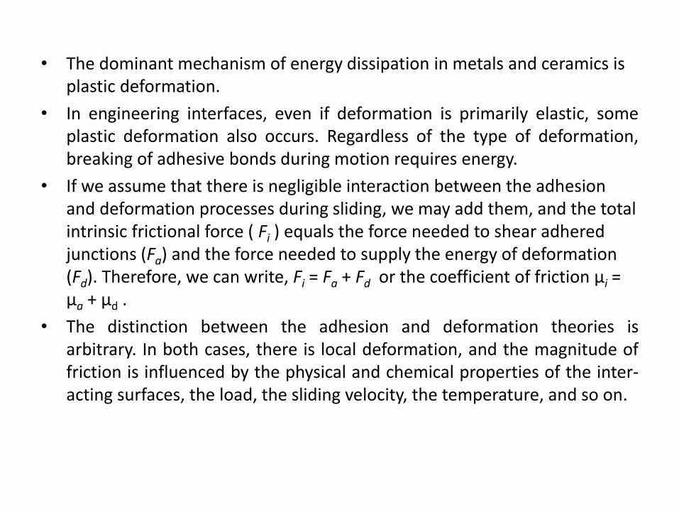
• The dominant mechanism of energy dissipation in metals and ceramics is plastic deformation.
• In engineering interfaces, even if deformation is primarily elastic, someplastic deformation also occurs. Regardless of the type of deformation,breaking of adhesive bonds during motion requires energy.
• If we assume that there is negligible interaction between the adhesion and deformation processes during sliding, we may add them, and the total intrinsic frictional force ( Fi ) equals the force needed to shear adhered junctions (Fa) and the force needed to supply the energy of deformation (Fd). Therefore, we can write, Fi = Fa + Fd or the coefficient of friction μi = μa + μd .
• The distinction between the adhesion and deformation theories isarbitrary. In both cases, there is local deformation, and the magnitude offriction is influenced by the physical and chemical properties of the inter-acting surfaces, the load, the sliding velocity, the temperature, and so on.
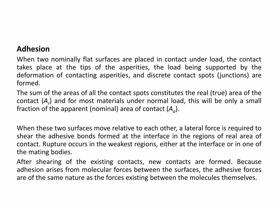
AdhesionWhen two nominally flat surfaces are placed in contact under load, the contacttakes place at the tips of the asperities, the load being supported by thedeformation of contacting asperities, and discrete contact spots (junctions) areformed.
The sum of the areas of all the contact spots constitutes the real (true) area of thecontact (Ar) and for most materials under normal load, this will be only a smallfraction of the apparent (nominal) area of contact (Aa).
When these two surfaces move relative to each other, a lateral force is required toshear the adhesive bonds formed at the interface in the regions of real area ofcontact. Rupture occurs in the weakest regions, either at the interface or in one ofthe mating bodies.
After shearing of the existing contacts, new contacts are formed. Becauseadhesion arises from molecular forces between the surfaces, the adhesive forcesare of the same nature as the forces existing between the molecules themselves.
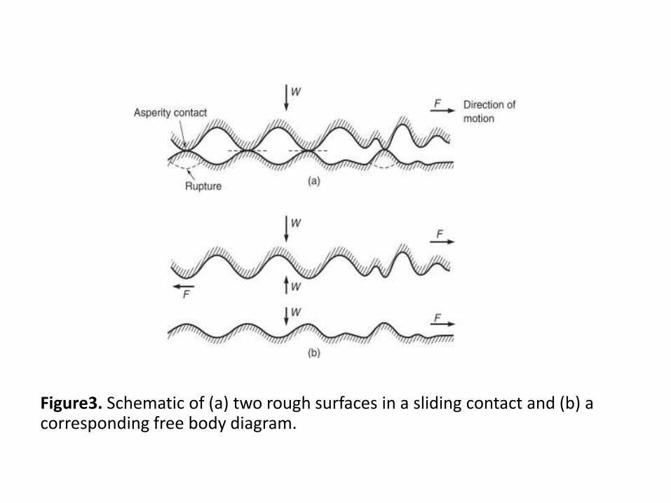
Figure3. Schematic of (a) two rough surfaces in a sliding contact and (b) a corresponding free body diagram.
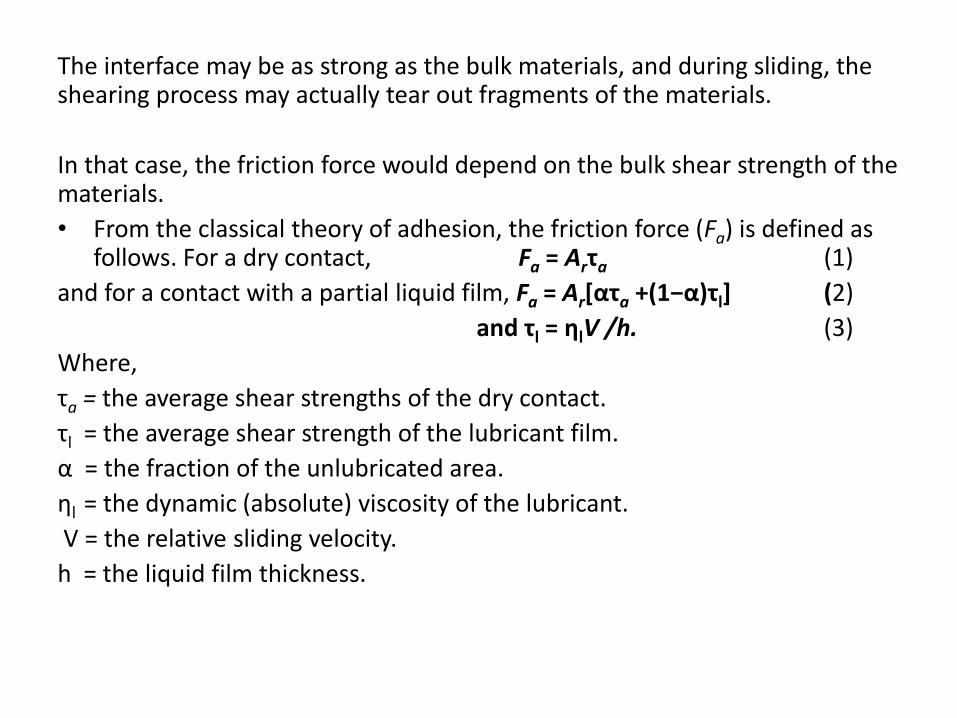
The interface may be as strong as the bulk materials, and during sliding, the shearing process may actually tear out fragments of the materials.
In that case, the friction force would depend on the bulk shear strength of the materials.
• From the classical theory of adhesion, the friction force (Fa) is defined as follows. For a dry contact, Fa = Arτa (1)
and for a contact with a partial liquid film, Fa = Ar[ατa +(1−α)τl] (2)
and τl = ηlV /h. (3)
Where,
τa = the average shear strengths of the dry contact.
τl = the average shear strength of the lubricant film.
α = the fraction of the unlubricated area.
ηl = the dynamic (absolute) viscosity of the lubricant.
V = the relative sliding velocity.
h = the liquid film thickness.
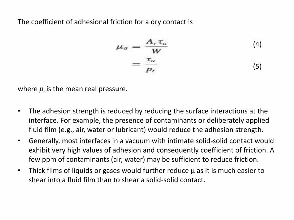
The coefficient of adhesional friction for a dry contact is
(4)
(5)
where pr is the mean real pressure.
• The adhesion strength is reduced by reducing the surface interactions at the interface. For example, the presence of contaminants or deliberately applied fluid film (e.g., air, water or lubricant) would reduce the adhesion strength.
• Generally, most interfaces in a vacuum with intimate solid-solid contact would exhibit very high values of adhesion and consequently coefficient of friction. A few ppm of contaminants (air, water) may be sufficient to reduce friction.
• Thick films of liquids or gases would further reduce μ as it is much easier to shear into a fluid film than to shear a solid-solid contact.
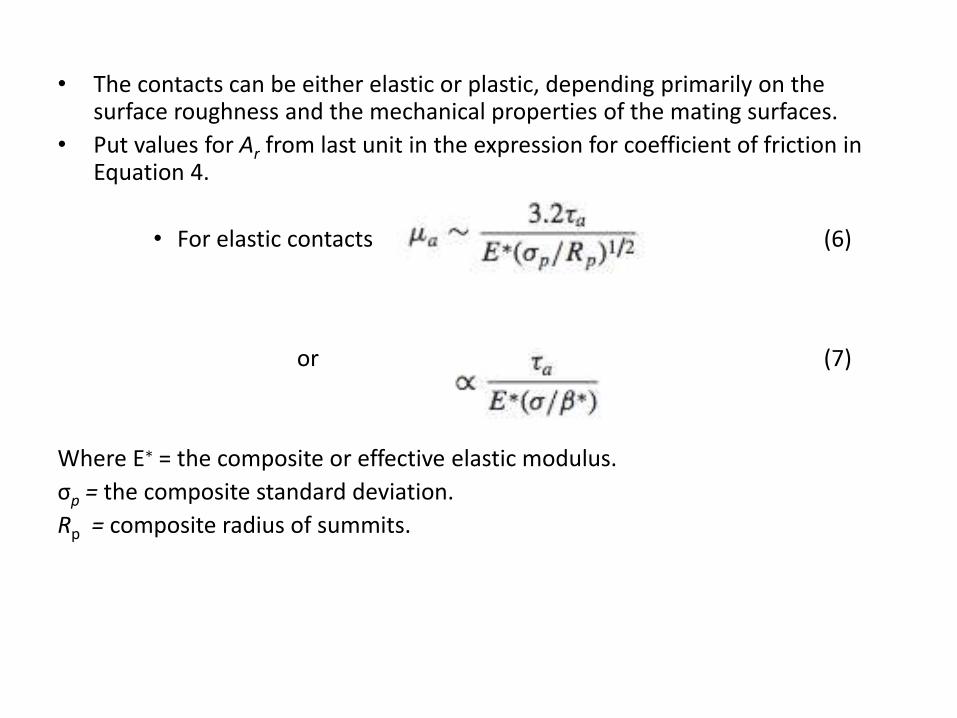
• The contacts can be either elastic or plastic, depending primarily on the surface roughness and the mechanical properties of the mating surfaces.
• Put values for Ar from last unit in the expression for coefficient of friction in Equation 4.
• For elastic contacts (6)
or (7)
Where E∗ = the composite or effective elastic modulus.
σp = the composite standard deviation.
Rp = composite radius of summits.
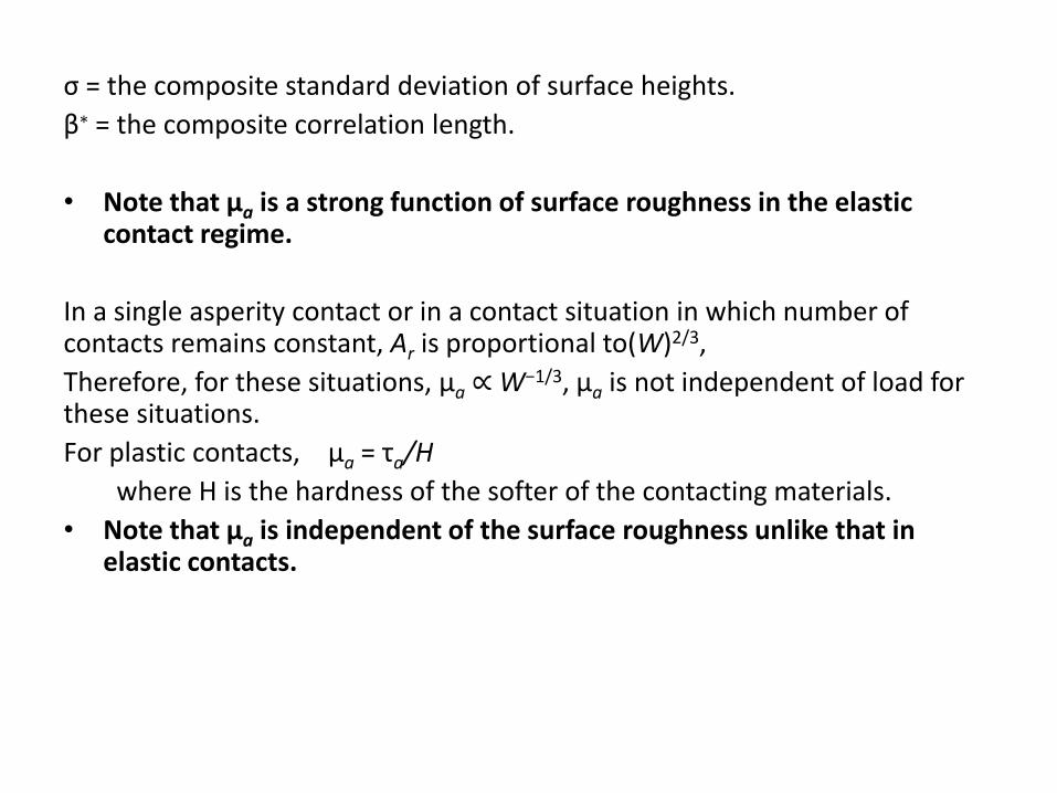
σ = the composite standard deviation of surface heights.
β∗ = the composite correlation length.
• Note that μa is a strong function of surface roughness in the elastic contact regime.
In a single asperity contact or in a contact situation in which number of contacts remains constant, Ar is proportional to(W)2/3,
Therefore, for these situations, μa ∝ W−1/3, μa is not independent of load for these situations.
For plastic contacts, μa = τa/H
where H is the hardness of the softer of the contacting materials.
• Note that μa is independent of the surface roughness unlike that in elastic contacts.
• Calculation of μa requires knowledge of τa .
• By using the analysis, it can be seen that the interfacial shear strength τa
cannot substantially exceed the bulk shear strength k (the yield strength in shear) of the softer of the contacting materials for plastic contacts.
• If it did, each contact spot would shear within the softer material. For ductile metals, H ∼ 5k
therefore, μa ≤ 1/5.
• The maximum value is independent of the metal pair. The predicted value is much smaller than the typical values observed under sliding, which typically range from 0.3 to greater than 1.
• The analysis so far includes an adhesional effect without other factors such as contact area growth and does not include other sources of friction such as deformation.

Adhesional Friction of Plastics
The shear strength of most solids is a function of the contact conditions such as mean contact pressure (real pressure).
For plastics and some nonmetals, τa = τ0 + αpr (8)
And
μa = τ0 /pr + α (9)
Where τ0 = intrinsic characteristic shear strength
α = pressure coefficient
• For metals, the term τ0/pr is often as large as or larger than α.
• For polymers and some nonmetals, it turns out that τ0/pr is small compared to α.
• For organic materials, α is on the order of 0.2. The coefficient of friction of these materials will be very close to α.
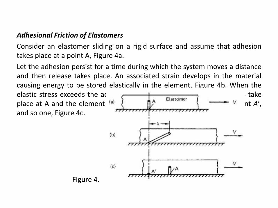
Adhesional Friction of Elastomers
Consider an elastomer sliding on a rigid surface and assume that adhesiontakes place at a point A, Figure 4a.
Let the adhesion persist for a time during which the system moves a distanceand then release takes place. An associated strain develops in the materialcausing energy to be stored elastically in the element, Figure 4b. When theelastic stress exceeds the adhesive force, failure of the adhesive bonds takeplace at A and the element relaxes. Adhesion takes place at a new point A′,and so one, Figure 4c.
Figure 4.
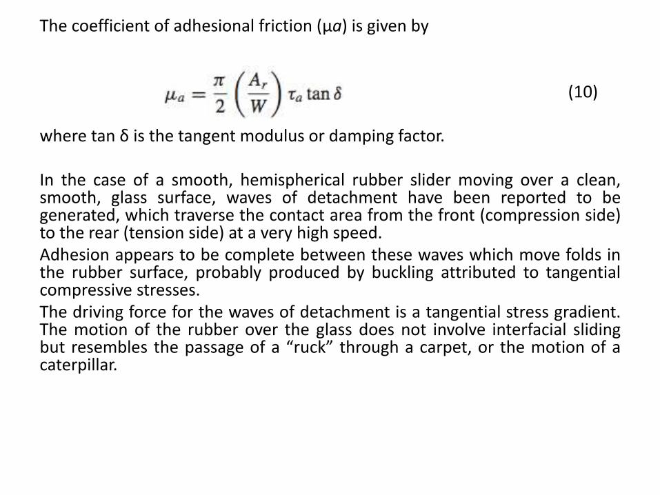
The coefficient of adhesional friction (μa) is given by
(10)
where tan δ is the tangent modulus or damping factor.
In the case of a smooth, hemispherical rubber slider moving over a clean,smooth, glass surface, waves of detachment have been reported to begenerated, which traverse the contact area from the front (compression side)to the rear (tension side) at a very high speed.Adhesion appears to be complete between these waves which move folds inthe rubber surface, probably produced by buckling attributed to tangentialcompressive stresses.The driving force for the waves of detachment is a tangential stress gradient.The motion of the rubber over the glass does not involve interfacial slidingbut resembles the passage of a “ruck” through a carpet, or the motion of acaterpillar.
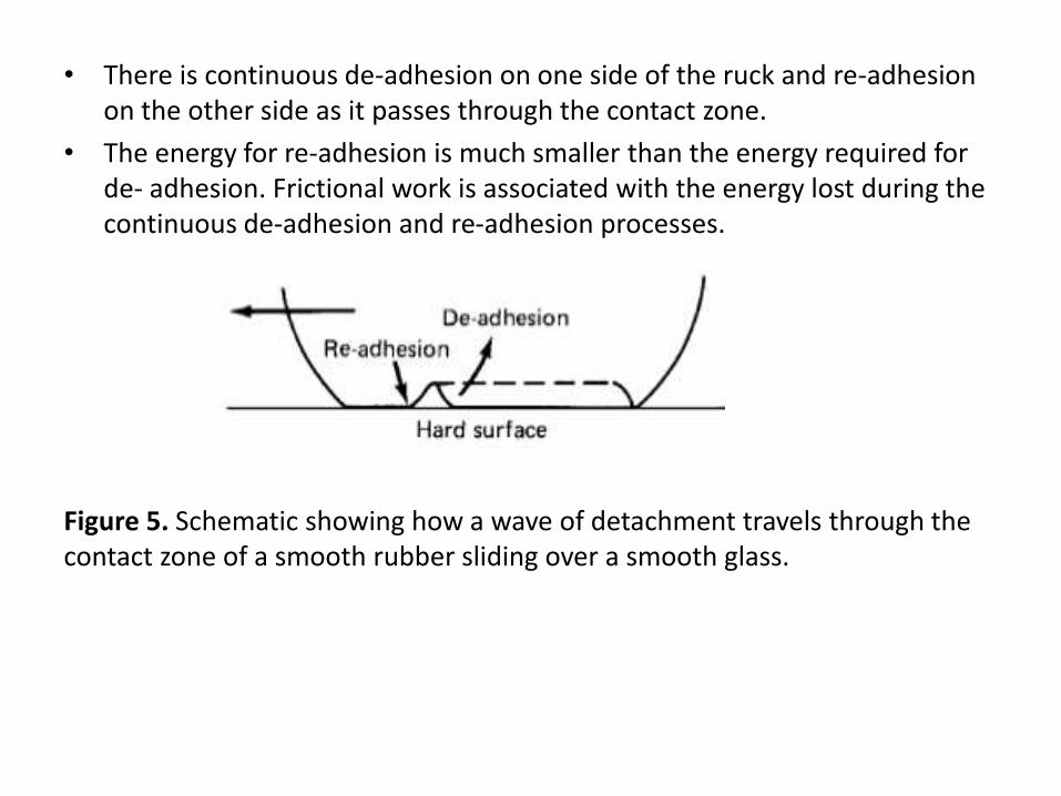
• There is continuous de-adhesion on one side of the ruck and re-adhesion on the other side as it passes through the contact zone.
• The energy for re-adhesion is much smaller than the energy required for de- adhesion. Frictional work is associated with the energy lost during the continuous de-adhesion and re-adhesion processes.
Figure 5. Schematic showing how a wave of detachment travels through the contact zone of a smooth rubber sliding over a smooth glass.
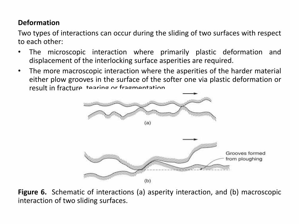
Deformation
Two types of interactions can occur during the sliding of two surfaces with respectto each other:
• The microscopic interaction where primarily plastic deformation anddisplacement of the interlocking surface asperities are required.
• The more macroscopic interaction where the asperities of the harder materialeither plow grooves in the surface of the softer one via plastic deformation orresult in fracture, tearing or fragmentation.
Figure 6. Schematic of interactions (a) asperity interaction, and (b) macroscopicinteraction of two sliding surfaces.
Plowing of one or both surfaces can also occur by wear particles trappedbetween them.
• The macroscopic plowing of the softer material by the harder, with thedimensions of the plowed groove being orders of magnitude greater thanthose of the asperities on either surface.
• Plowing deals with relatively large-volume deformations and small strains,whereas the shearing mechanism and local asperity interactions involvevery thin, interfacial regions and large strains.
• The plowing contribution may or may not be significant; its magnitudedepends on the surface roughnesses and relative hardnesses of the twosurfaces, and on the size, shape and hardness of any wear debris andreaction products trapped between them.
• If one of the sliding surfaces is harder than the other, the asperities of the harder surface may penetrate and plow into the softer surface and produce grooves if shear strength is exceeded.
• Plowing into the softer surface may also occur as a result of impactedwear particles. In addition, interaction of two rather rough surfaces mayresult in mechanical interlocking on a micro- or macroscale.
• During sliding, interlocking would result in plowing of one of the surfaces.
• Because of the plowing displacement, a certain lateral (friction) force isrequired to maintain motion.
• Plowing not only increases the friction force, it creates wear particles,which in turn increase subsequent friction and wear.
We now calculate the plowing component of the friction force for four modelrigid asperities or trapped wear particles – conical, spherical and cylindricalwith two orientations.
First, we consider a circular cone of roughness angle, or attackangle, θ, pressed into a softer body.
During sliding only the front surface of the asperity is in contactwith the softer body.
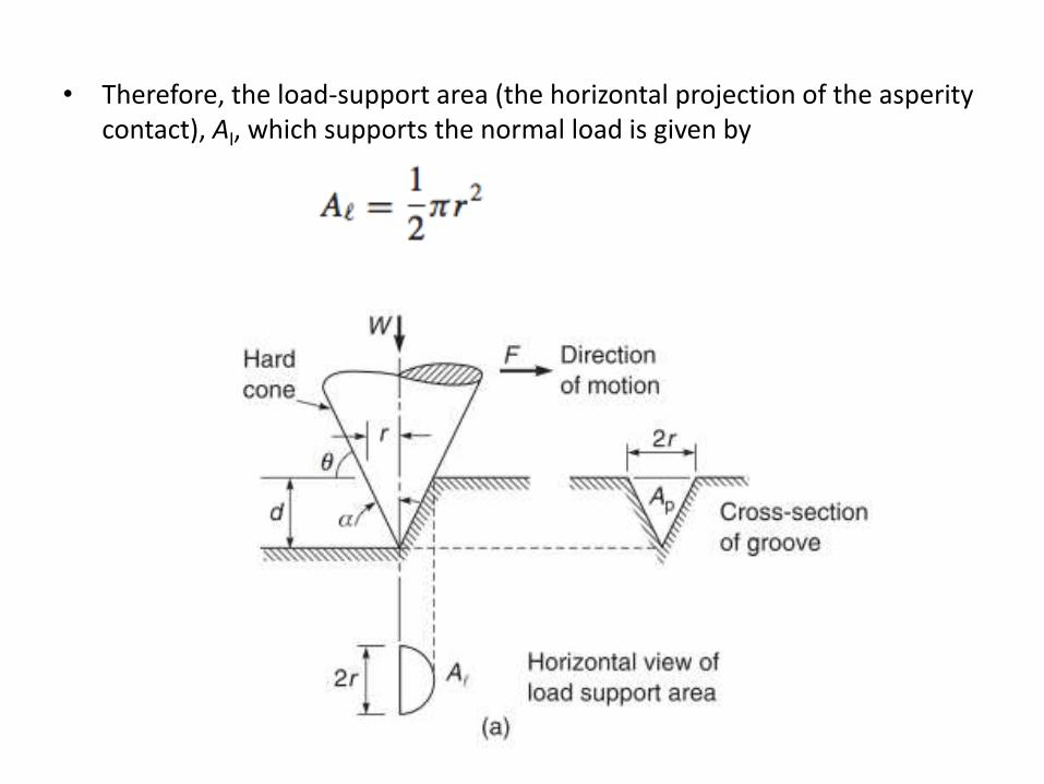
• Therefore, the load-support area (the horizontal projection of the asperity contact), Al, which supports the normal load is given by
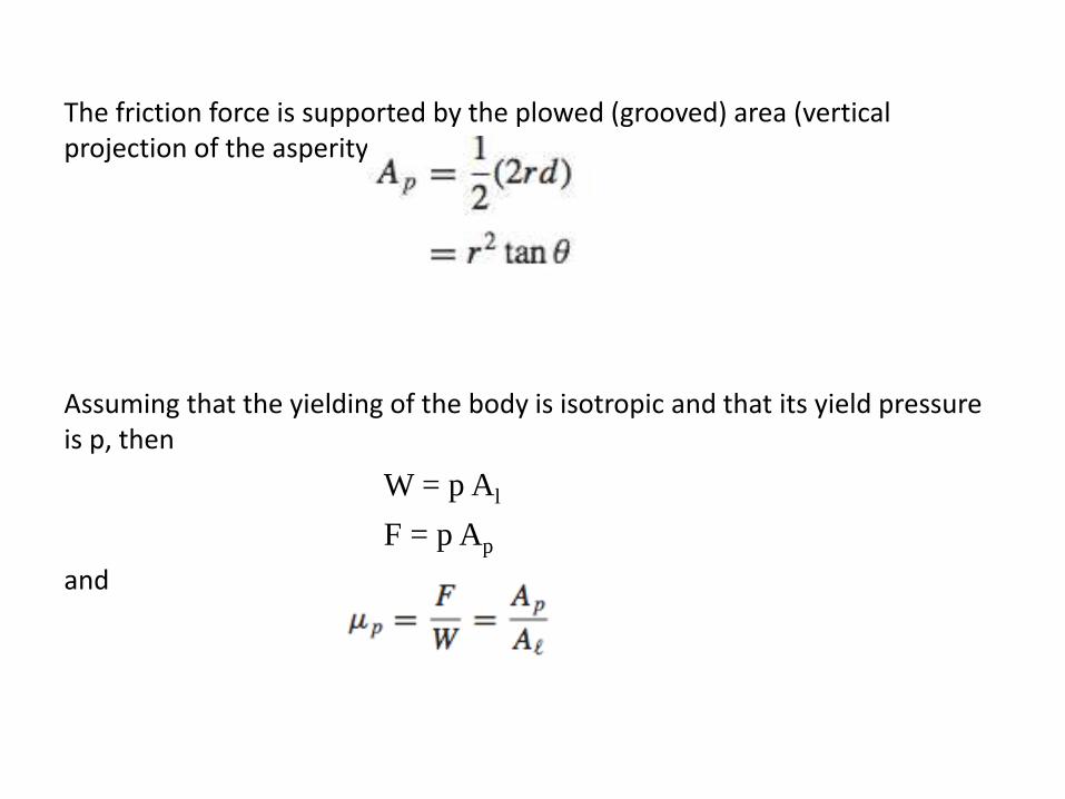
The friction force is supported by the plowed (grooved) area (vertical projection of the asperity contact), Ap and
Assuming that the yielding of the body is isotropic and that its yield pressure is p, then
W = p Al
F = p Ap
and
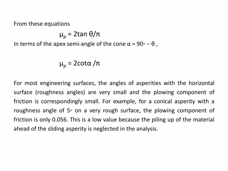
From these equations
μp = 2tan θ/π In terms of the apex semi-angle of the cone α = 90◦ − θ ,
μp = 2cotα /π
For most engineering surfaces, the angles of asperities with the horizontal
surface (roughness angles) are very small and the plowing component of
friction is correspondingly small. For example, for a conical asperity with a
roughness angle of 5◦ on a very rough surface, the plowing component of
friction is only 0.056. This is a low value because the piling up of the material
ahead of the sliding asperity is neglected in the analysis.
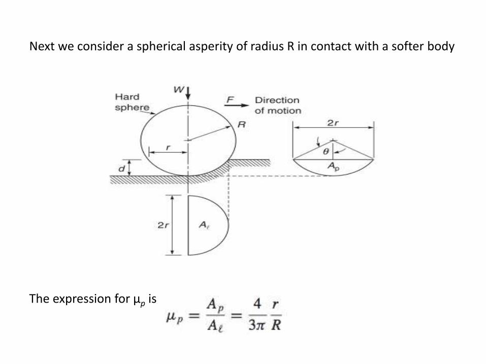
Next we consider a spherical asperity of radius R in contact with a softer body
The expression for μp is
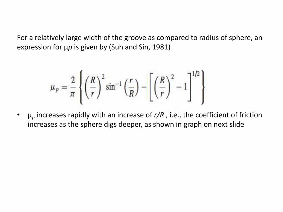
For a relatively large width of the groove as compared to radius of sphere, an expression for μp is given by (Suh and Sin, 1981)
• μp increases rapidly with an increase of r/R , i.e., the coefficient of friction increases as the sphere digs deeper, as shown in graph on next slide
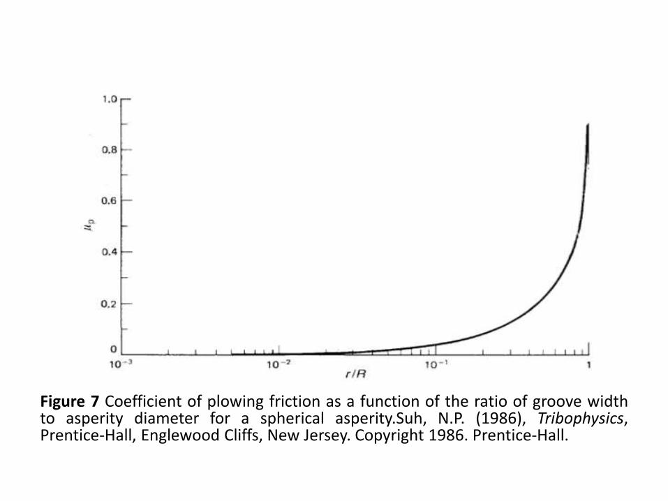
Figure 7 Coefficient of plowing friction as a function of the ratio of groove widthto asperity diameter for a spherical asperity.Suh, N.P. (1986), Tribophysics,Prentice-Hall, Englewood Cliffs, New Jersey. Copyright 1986. Prentice-Hall.
Hysteresis
A deformation (hysteresis) component of friction occurs in viscoelasticmaterials (such as polymers) in the so-called elastic limit, because of elastichysteresis losses.
For most metals, the fraction of energy lost in the elastic limit < 1%, but forviscoelastic materials such as polymers (especially elastomers), it may belarge.
During sliding, the material is first stressed and then the stress is released assliding continues and the point of contact moves on as in figure 8.
The tangential force produces an increase in deformation ahead of theindenter.
Each time an element of volume is stressed, elastic energy is taken up by it.Most of the energy is later released as the stress is removed from theelement of the body, but a small part is lost (in the form of heat) as a result ofelastic hysteresis losses.
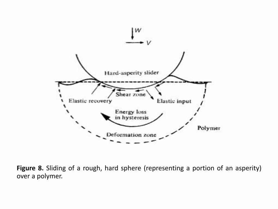
Figure 8. Sliding of a rough, hard sphere (representing a portion of an asperity)over a polymer.
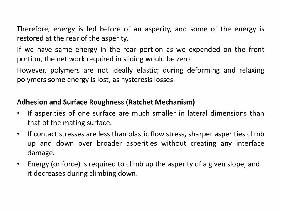
Therefore, energy is fed before of an asperity, and some of the energy isrestored at the rear of the asperity.
If we have same energy in the rear portion as we expended on the frontportion, the net work required in sliding would be zero.
However, polymers are not ideally elastic; during deforming and relaxingpolymers some energy is lost, as hysteresis losses.
Adhesion and Surface Roughness (Ratchet Mechanism)
• If asperities of one surface are much smaller in lateral dimensions thanthat of the mating surface.
• If contact stresses are less than plastic flow stress, sharper asperities climbup and down over broader asperities without creating any interfacedamage.
• Energy (or force) is required to climb up the asperity of a given slope, and it decreases during climbing down.
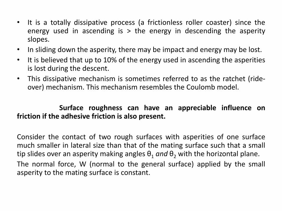
• It is a totally dissipative process (a frictionless roller coaster) since theenergy used in ascending is > the energy in descending the asperityslopes.
• In sliding down the asperity, there may be impact and energy may be lost.
• It is believed that up to 10% of the energy used in ascending the asperitiesis lost during the descent.
• This dissipative mechanism is sometimes referred to as the ratchet (ride-over) mechanism. This mechanism resembles the Coulomb model.
Surface roughness can have an appreciable influence onfriction if the adhesive friction is also present.
Consider the contact of two rough surfaces with asperities of one surfacemuch smaller in lateral size than that of the mating surface such that a smalltip slides over an asperity making angles θ1 and θ2 with the horizontal plane.
The normal force, W (normal to the general surface) applied by the smallasperity to the mating surface is constant.
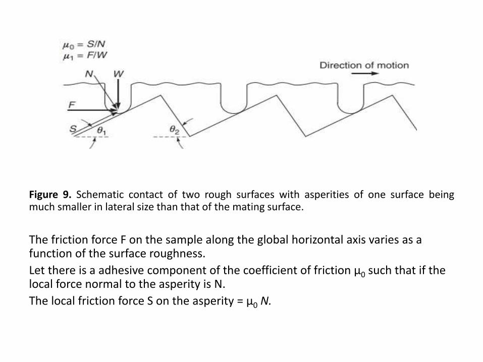
Figure 9. Schematic contact of two rough surfaces with asperities of one surface beingmuch smaller in lateral size than that of the mating surface.
The friction force F on the sample along the global horizontal axis varies as a function of the surface roughness.
Let there is a adhesive component of the coefficient of friction μ0 such that if the local force normal to the asperity is N.
The local friction force S on the asperity = μ0 N.
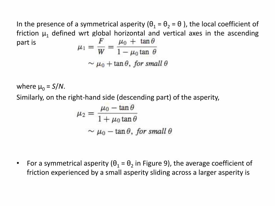
In the presence of a symmetrical asperity (θ1 = θ2 = θ ), the local coefficient offriction μ1 defined wrt global horizontal and vertical axes in the ascendingpart is
where μ0 = S/N.
Similarly, on the right-hand side (descending part) of the asperity,
• For a symmetrical asperity (θ1 = θ2 in Figure 9), the average coefficient of friction experienced by a small asperity sliding across a larger asperity is
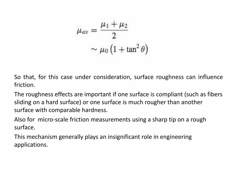
So that, for this case under consideration, surface roughness can influencefriction.
The roughness effects are important if one surface is compliant (such as fibers sliding on a hard surface) or one surface is much rougher than another surface with comparable hardness.
Also for micro-scale friction measurements using a sharp tip on a rough surface.
This mechanism generally plays an insignificant role in engineering applications.
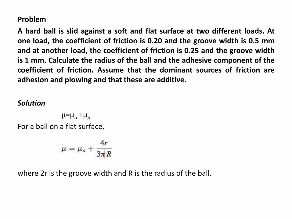
Problem
A hard ball is slid against a soft and flat surface at two different loads. Atone load, the coefficient of friction is 0.20 and the groove width is 0.5 mmand at another load, the coefficient of friction is 0.25 and the groove widthis 1 mm. Calculate the radius of the ball and the adhesive component of thecoefficient of friction. Assume that the dominant sources of friction areadhesion and plowing and that these are additive.
Solution
μ=μa +μp
For a ball on a flat surface,
where 2r is the groove width and R is the radius of the ball.
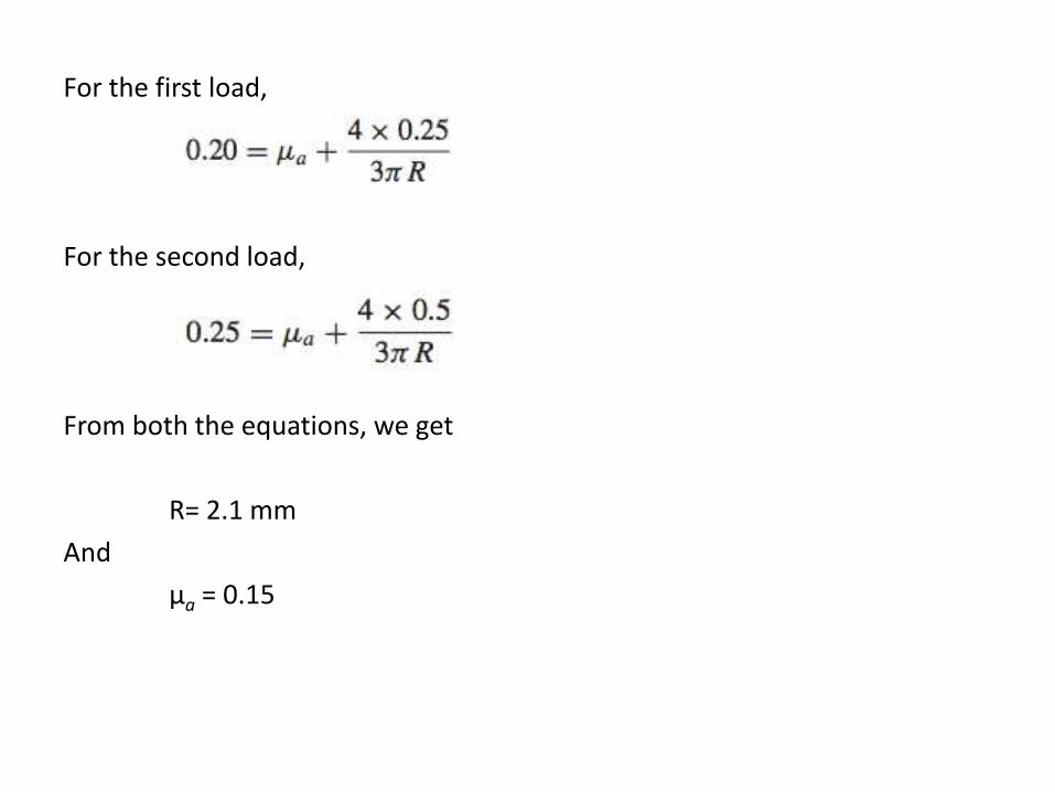
For the first load,
For the second load,
From both the equations, we get
R= 2.1 mm
And
μa = 0.15
Other Mechanisms of Sliding Friction
Structural Effects
Hexagonal close-packed (HCP) metals exhibit low coefficient of friction (about30%) less and much less wear (about a factor of ten less) than face-centeredcubic (FCC) metals.
One key factor that affects friction and wear is the number of slip planes.
Hexagonal metals (c/a ∼ 1.628 for HCP metals) have a limited number of slipplanes.
Five slip planes are required so that, as two rough surfaces deform, at eachcontact there is perfect conformance between one surface and the other.
In contrast, cubic metals, which have 12 slip planes, have no such air gaps,and for this reason the contact is stronger, and the friction and wearcorrespondingly higher.
Grain Boundary Effects
Strained metal, i.e., metal that contains a high concentration of dislocations, ischemically more active on the surface because of the presence of defectsincreases the energy in the material.
A grain boundary is a strained condition in which there are many dislocationspresent to help accommodate the misfit or mismatch in adjacent orientations,and there are rows of strained atoms that must help in accommodating themismatch.
These regions are high- energy regions at the surface. The energy is greater at theboundary, and the boundary has its own characteristic energy that is separate anddistinct from the energy of the grains on either side of the boundary.
• For polycrystalline materials, the presence of grain boundaries in the materialinfluences adhesion and friction behavior, surface fracture, and wear. The nearsurface dislocations in the sliding process are blocked in their movement by agrain boundary, they accumulate at the grain boundary and produce strainhardening. This strain hardening makes sliding more difficult and increases thefriction force of materials in sliding contact .
Rolling Friction It is much easier to roll surfaces than to slide them.
Rolling friction is the resistance to motion that takes place when a surface isrolled over another surface. The term rolling friction is usually restricted tobodies of near perfect (continuous) shapes with very small surface roughness.
With hard materials, the coefficient of rolling friction between a cylindrical orspherical body against itself or a flat body generally is in the range of 5 × 10⁻³
to 10−5.
In comparison, the coefficient of sliding friction of dry bodies ranges typically from 0.1 to sometimes much greater than 1.
During rolling of two surfaces relative to each other, any relative motion can be regarded as a combination of rolling, sliding and spin (Johnson, 1985).
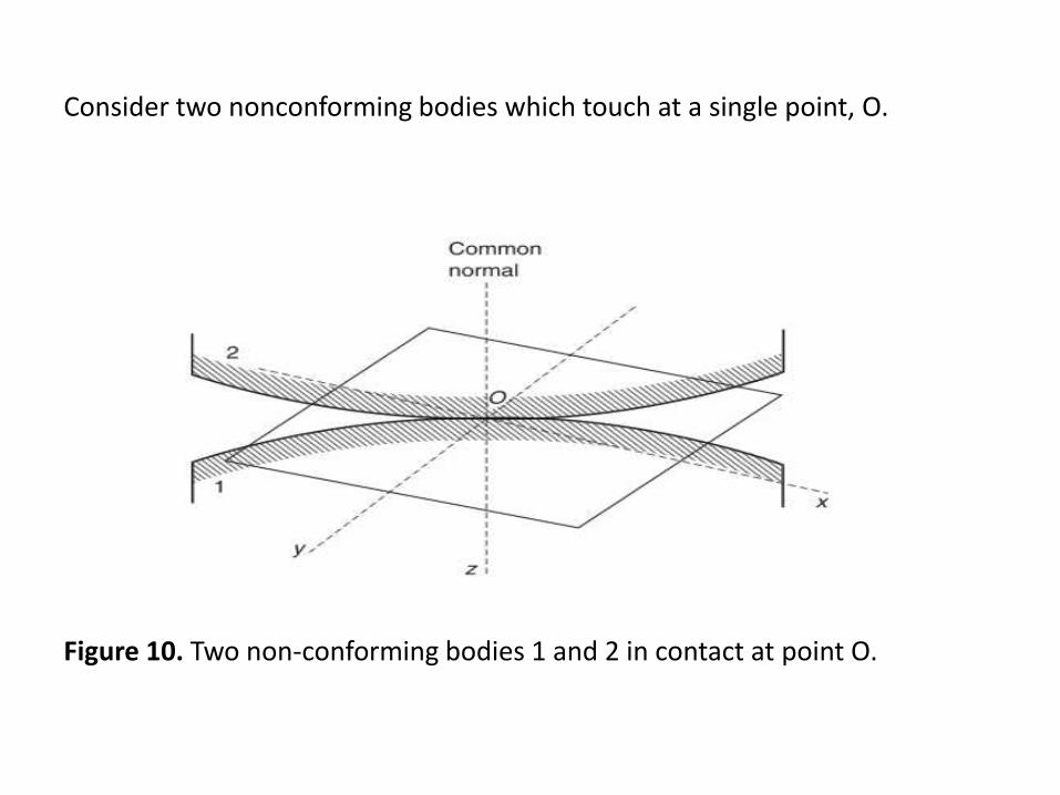
Consider two nonconforming bodies which touch at a single point, O.
Figure 10. Two non-conforming bodies 1 and 2 in contact at point O.
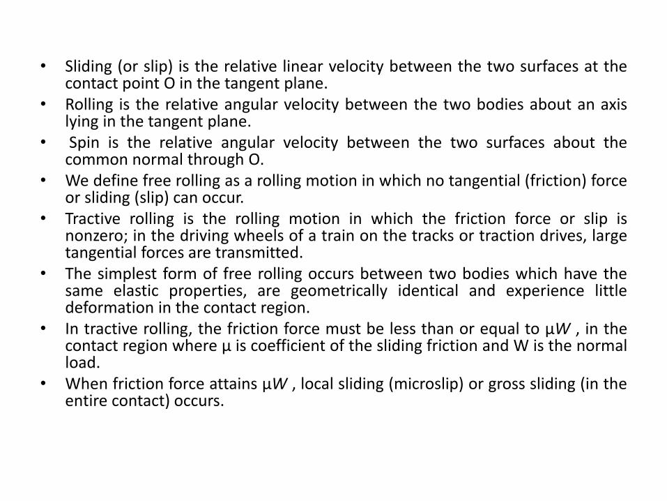
• Sliding (or slip) is the relative linear velocity between the two surfaces at thecontact point O in the tangent plane.
• Rolling is the relative angular velocity between the two bodies about an axislying in the tangent plane.
• Spin is the relative angular velocity between the two surfaces about thecommon normal through O.
• We define free rolling as a rolling motion in which no tangential (friction) forceor sliding (slip) can occur.
• Tractive rolling is the rolling motion in which the friction force or slip isnonzero; in the driving wheels of a train on the tracks or traction drives, largetangential forces are transmitted.
• The simplest form of free rolling occurs between two bodies which have thesame elastic properties, are geometrically identical and experience littledeformation in the contact region.
• In tractive rolling, the friction force must be less than or equal to μW , in thecontact region where μ is coefficient of the sliding friction and W is the normalload.
• When friction force attains μW , local sliding (microslip) or gross sliding (in theentire contact) occurs.
Types of Slip Three different cases of microslip are discussed as follows:
• First, we consider a Hertizian contact of two nonconforming bodies havingdifferent elastic constants.
• If the two bodies roll freely together, the load that acts on each gives rise tounequal tangential displacements of the surfaces, leading to slip at theinterface. This type of slip is called Reynolds slip (Reynolds, 1876).
• Next, we consider tractive rolling of two nonconforming bodies having thesame elastic properties, subjected to a tangential force which is less thanrequired to cause gross sliding.
• For tractive rolling of elastically similar cylinders, the stick (no slip) regioncoincides with the leading edge of the rectangular contact area and the slip isconfined to the trailing edge. As the tangential force increases, the slip zoneextends forward until F = μW holds across the whole area and gross slidingoccurs. In contrast, in the two stationary cylinders subjected to a tangentialforce, there is a central stick area and two outer slip areas.
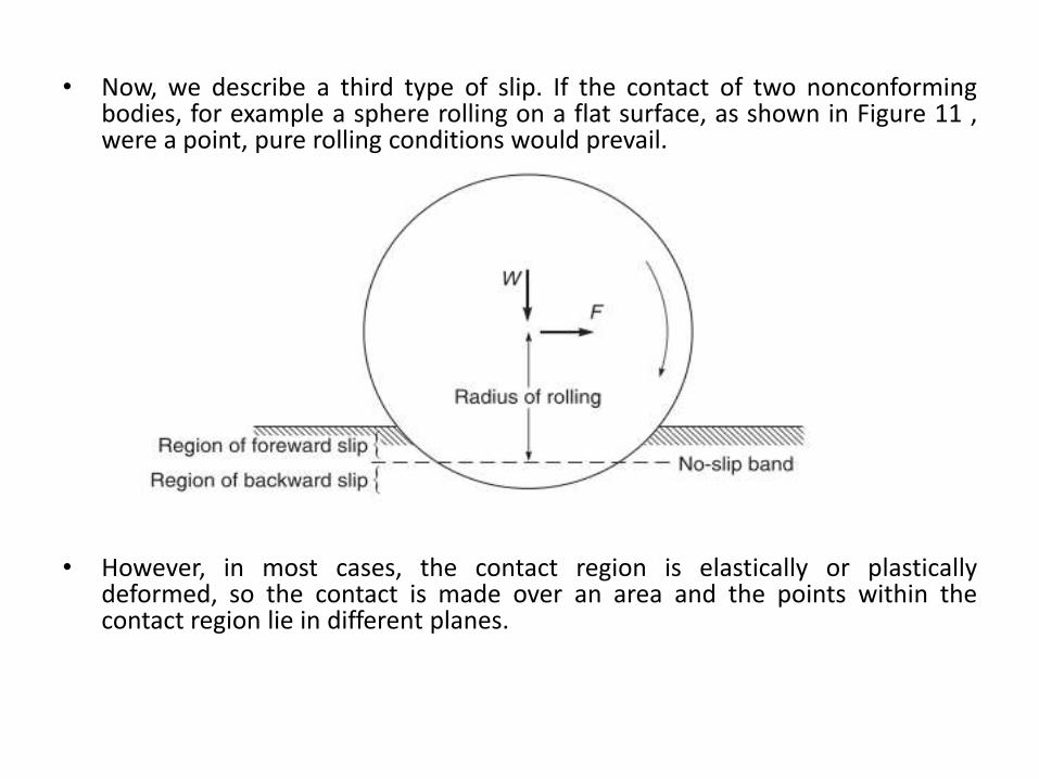
• Now, we describe a third type of slip. If the contact of two nonconformingbodies, for example a sphere rolling on a flat surface, as shown in Figure 11 ,were a point, pure rolling conditions would prevail.
• However, in most cases, the contact region is elastically or plasticallydeformed, so the contact is made over an area and the points within thecontact region lie in different planes.
• As a result, pure rolling takes place at a very small number of points but acombination of rolling with a small degree of sliding or slip takes place atall other points.
• In many engineering applications, such as a ball rolling along a groovedtrack in ball bearings, the contact area lies in very different planes, Fig 12.
• During rolling of the ball through one complete revolution along thegrooved track, the center of the ball measures out its full diameter 2Ralong the track.
• The points on the ball at the edges of the contact zone measure out asmaller distance corresponding to radius Rr .
• These differences can be accommodated by the ball slipping in its tracksimilar to the ball on a deformed track on a flat surface just described.
• The contact area in either case consists of three zones of slip - a singlecentral zone of backward slip and two outer zones of forward slips.
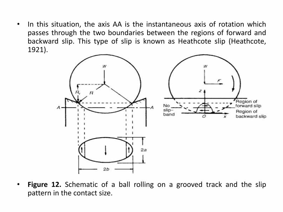
• In this situation, the axis AA is the instantaneous axis of rotation whichpasses through the two boundaries between the regions of forward andbackward slip. This type of slip is known as Heathcote slip (Heathcote,1921).
• Figure 12. Schematic of a ball rolling on a grooved track and the slippattern in the contact size.
Mechanisms of Rolling Friction In the case of rolling contacts, rolling friction arises from the resistance to rollingand because of slip.
The magnitude of the resistance to rolling is usually much less than that duringslip.
For sliding, energy dissipation in rolling also occurs due to adhesive losses anddeformation losses (plastic deformation or elastic hysteresis) during stress cyclingof the contacting surfaces.
The joining and separation of surface elements under rolling contacts are littledifferent from those of sliding contacts.
The surface elements approach and separate in a direction normal to theinterface rather than in a tangential direction.
Therefore, contact growth is unlikely in the main part of the contact area.
At the regions within the rolling contact interface where no relative motion in atangential direction occurs, adhesive forces may be mainly of the van der Waalstype.
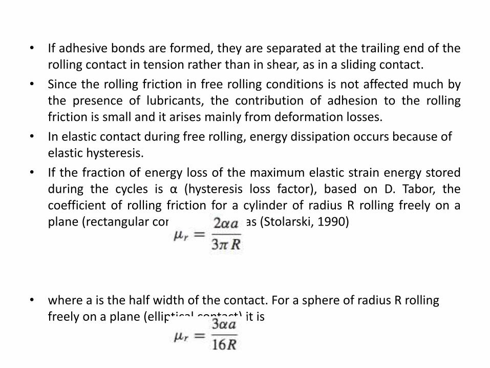
• If adhesive bonds are formed, they are separated at the trailing end of therolling contact in tension rather than in shear, as in a sliding contact.
• Since the rolling friction in free rolling conditions is not affected much bythe presence of lubricants, the contribution of adhesion to the rollingfriction is small and it arises mainly from deformation losses.
• In elastic contact during free rolling, energy dissipation occurs because of elastic hysteresis.
• If the fraction of energy loss of the maximum elastic strain energy storedduring the cycles is α (hysteresis loss factor), based on D. Tabor, thecoefficient of rolling friction for a cylinder of radius R rolling freely on aplane (rectangular contact) is given as (Stolarski, 1990)
• where a is the half width of the contact. For a sphere of radius R rolling freely on a plane (elliptical contact) it is
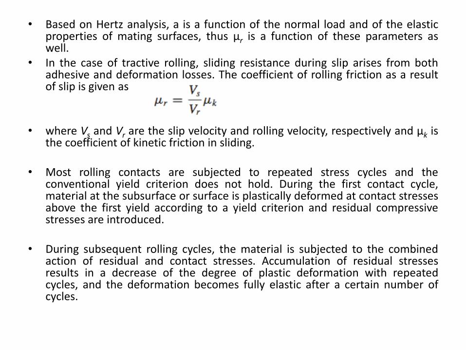
• Based on Hertz analysis, a is a function of the normal load and of the elasticproperties of mating surfaces, thus μr is a function of these parameters aswell.
• In the case of tractive rolling, sliding resistance during slip arises from bothadhesive and deformation losses. The coefficient of rolling friction as a resultof slip is given as
• where Vs and Vr are the slip velocity and rolling velocity, respectively and μk isthe coefficient of kinetic friction in sliding.
• Most rolling contacts are subjected to repeated stress cycles and theconventional yield criterion does not hold. During the first contact cycle,material at the subsurface or surface is plastically deformed at contact stressesabove the first yield according to a yield criterion and residual compressivestresses are introduced.
• During subsequent rolling cycles, the material is subjected to the combinedaction of residual and contact stresses. Accumulation of residual stressesresults in a decrease of the degree of plastic deformation with repeatedcycles, and the deformation becomes fully elastic after a certain number ofcycles.
Friction of Materials The coefficient of friction of a material is dependent upon the counter face ormating material (or material pair), surface preparation and operatingconditions. For example, material handling, such as the transfer of greasymaterials from hands to the material surface, and the formation of chemicallyreacted products due to exposure to an environment, can change the surface
chemistry, which may significantly affect the frictional properties.
Friction of Metals and Alloys
The clean metal and alloy surfaces in contact exhibit high adhesion, andconsequently high friction and wear. The coefficient of friction of contactingmetallic surfaces cleaned in a high vacuum, can be very high, typically 2 andmuch higher.
Strong metallic bonds are formed across the interface and significant transferof metal from one body to another, or as loose wear debris, occurs duringsliding.
• The slightest contamination mitigates contact or forms chemical films whichreduce adhesion resulting in reduction of the friction.
• Most metals oxidize in air to some extent and form oxide films, typicallybetween 1 and 10 nm thick within a few minutes of exposure of an atomicclean surface.
• The oxide film acts as a low shear-strength film and in addition because of low ductility leads to low friction.
• The oxide film may effectively separate the two metallic surfaces. However,during sliding, these thin oxide films may be penetrated.
• Also the film is penetrated at higher loads, and transition occurs to high valuesof friction.
• Transitions of this kind are common in metals, although the change in frictionvalue may not be as high as in copper. Some of the precious metals (such asAu) do not form oxide layers and exhibit high friction.
• For soft and ductile metals such as Pb and Sn, the contact area is large even atlow loads but the shear strength of the contacts may be low.
• The coefficient of friction is generally high because of large contact areas and small elastic recovery.
• Hexagonal metals such as Co and Mg as well as other non-hexagonal metalssuch as Mo and Cr exhibit low friction.
• Chromium forms a tenacious oxide film which is responsible for low friction.Co, Mo and Cr are common alloying elements in steels to reduce friction, wear,and corrosion.
• In general, the coefficient of friction for an alloy tends to be lower than that ofits pure components. Binary alloys of cobalt and chromium with more than10% Cr exhibit excellent resistance to oxidation and corrosion. Tungsten andmolybdenum are added to increase their strength and to improve friction andwear properties.
• Lead-based white metals (babbitts), brass and bronze and gray cast iron exhibit relatively low friction. All contain phases which form films of low shear strength.
• In the lead-based alloys, a thin film of lead is formed during sliding and in gray cast iron, the low shear strength film is provided by the graphite constituent.
• Thus, these alloys exhibit intrinsically low coefficients of friction in dry sliding against steel, which do not depend on the formation of a protective oxide layer. These alloys are commonly used as bearing and seal materials.
Effect of Operating Conditions
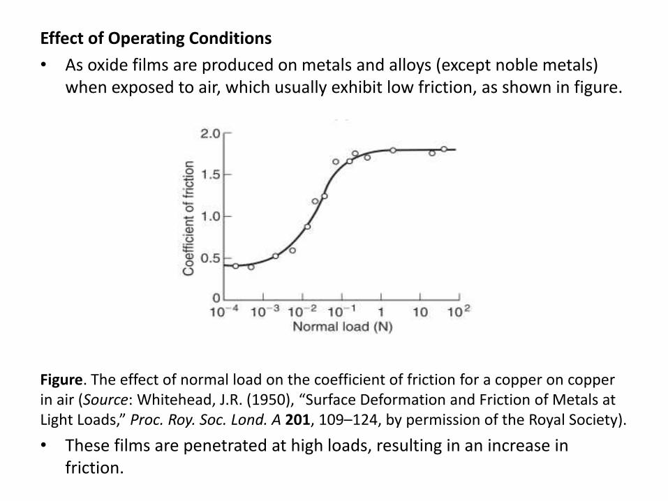
• As oxide films are produced on metals and alloys (except noble metals) when exposed to air, which usually exhibit low friction, as shown in figure.
Figure. The effect of normal load on the coefficient of friction for a copper on copper in air (Source: Whitehead, J.R. (1950), “Surface Deformation and Friction of Metals at Light Loads,” Proc. Roy. Soc. Lond. A 201, 109–124, by permission of the Royal Society).
• These films are penetrated at high loads, resulting in an increase in friction.
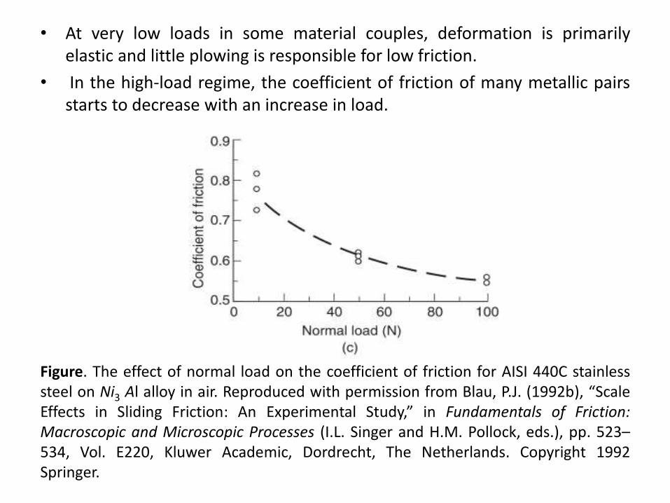
• At very low loads in some material couples, deformation is primarilyelastic and little plowing is responsible for low friction.
• In the high-load regime, the coefficient of friction of many metallic pairsstarts to decrease with an increase in load.
Figure. The effect of normal load on the coefficient of friction for AISI 440C stainlesssteel on Ni3 Al alloy in air. Reproduced with permission from Blau, P.J. (1992b), “ScaleEffects in Sliding Friction: An Experimental Study,” in Fundamentals of Friction:Macroscopic and Microscopic Processes (I.L. Singer and H.M. Pollock, eds.), pp. 523–534, Vol. E220, Kluwer Academic, Dordrecht, The Netherlands. Copyright 1992Springer.
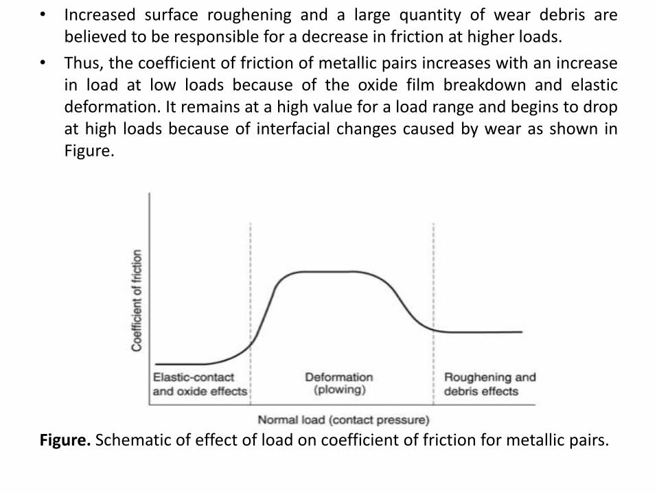
• Increased surface roughening and a large quantity of wear debris arebelieved to be responsible for a decrease in friction at higher loads.
• Thus, the coefficient of friction of metallic pairs increases with an increasein load at low loads because of the oxide film breakdown and elasticdeformation. It remains at a high value for a load range and begins to dropat high loads because of interfacial changes caused by wear as shown inFigure.
Figure. Schematic of effect of load on coefficient of friction for metallic pairs.
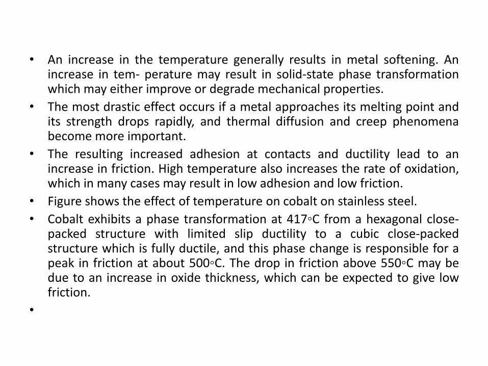
• An increase in the temperature generally results in metal softening. Anincrease in tem- perature may result in solid-state phase transformationwhich may either improve or degrade mechanical properties.
• The most drastic effect occurs if a metal approaches its melting point andits strength drops rapidly, and thermal diffusion and creep phenomenabecome more important.
• The resulting increased adhesion at contacts and ductility lead to anincrease in friction. High temperature also increases the rate of oxidation,which in many cases may result in low adhesion and low friction.
• Figure shows the effect of temperature on cobalt on stainless steel.
• Cobalt exhibits a phase transformation at 417◦C from a hexagonal close-packed structure with limited slip ductility to a cubic close-packedstructure which is fully ductile, and this phase change is responsible for apeak in friction at about 500◦C. The drop in friction above 550◦C may bedue to an increase in oxide thickness, which can be expected to give lowfriction.
•
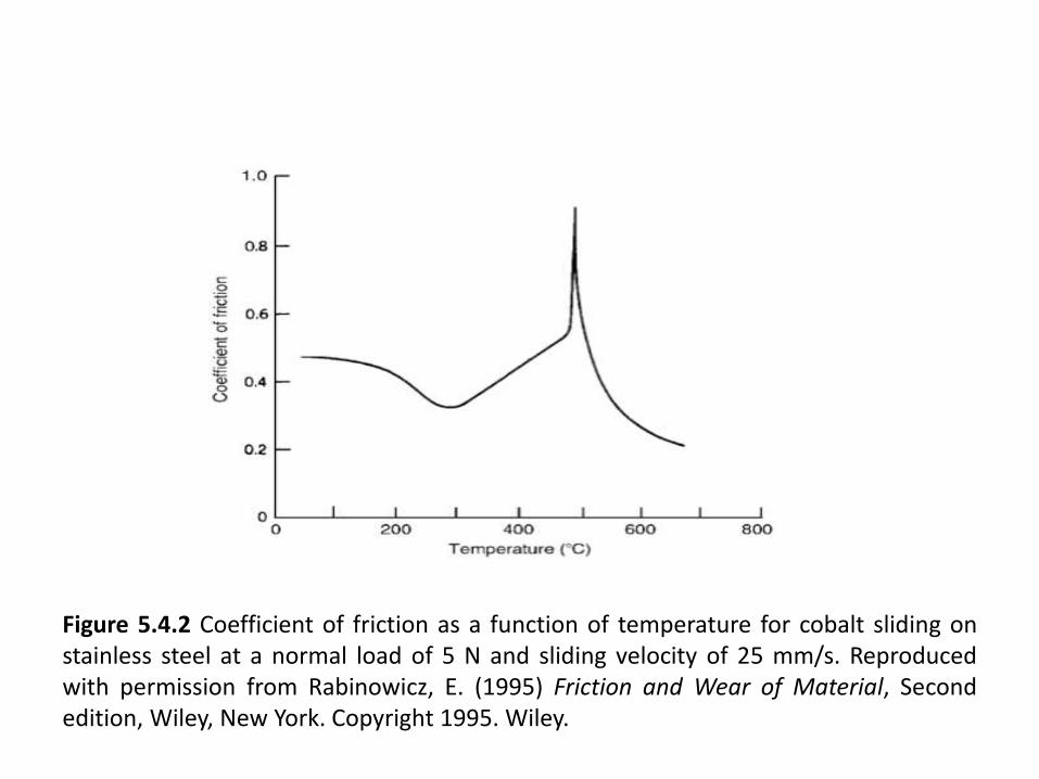
Figure 5.4.2 Coefficient of friction as a function of temperature for cobalt sliding onstainless steel at a normal load of 5 N and sliding velocity of 25 mm/s. Reproducedwith permission from Rabinowicz, E. (1995) Friction and Wear of Material, Secondedition, Wiley, New York. Copyright 1995. Wiley.