Embed Size (px)
Citation preview
X-rays and their interaction with matterShyue Ping OngDepartment of NanoEngineeringUniversity of California, San Diego

Readings¡Chapter 11 and 12 of Structure of Materials
NANO 106 - Crystallography of Materials by Shyue Ping Ong - Lecture 12
2

Overview¡ In part 1 of the course, we talked about
symmetries, point groups, space groups and lattices.
¡ In part 2, we discussed the consequences of symmetry on material properties.
¡Part 3 is going to be focused on the experimental methods for determining the structure of a material.
NANO 106 - Crystallography of Materials by Shyue Ping Ong - Lecture 12
3

X-ray crystallography¡Tool used for identifying the structure of a crystal
¡Crystalline (i.e., regular and repeating) arrangement of atoms cause a beam of incident X-rays to diffract into many specific directions.
¡3D picture of the density of electrons within the crystal can be obtained by measuring the angles and intensities of these diffracted beams. From this electron density, the mean positions of the atoms in the crystal can be determined, as well as their chemical bonds, their disorder and various other information.
NANO 106 - Crystallography of Materials by Shyue Ping Ong - Lecture 12
4

What are X-rays?¡ Form of electromagnetic (EM) radiation
¡ Travels at speed of light (c ~ 3 x 10⁸ m/s)
¡ Wavelength ~ 0.01-0.1 nm (same order of magnitude as spacing between atoms in a crystal)
NANO 106 - Crystallography of Materials by Shyue Ping Ong - Lecture 12
5
c = f λ where f is the frequency and λ is the wavelength.

Wave-particle duality¡ Like all EM radiation, X-rays can be regarded as a wave or a particle
(photon).
¡ Photon energy is given by where h is the Planck constant 6.626×10⁻³⁴ Js, ν is the frequency, λ is the wavelength and c is the speed of light.
¡ Wave: Electric field with perpendicular magnetic field, mathematically represented in 1D as:
NANO 106 - Crystallography of Materials by Shyue Ping Ong - Lecture 12
6
E = hν = hcλ
// to E×B
E(x, t) = Acos(2π (kx − ct))or using complex exponential notationE(x, t) = Ae2πi(kx−ct ) = Ae2πikxe−2πict
Spatial component
Temporalcomponent

Generalization to 3D¡ In 3D, the spatial component is simply
¡ Given that the argument to the exponent must be dimensionless, kmust have units of inverse length, i.e., k is a vector in reciprocal space!
¡ If we express k in reciprocal basis vectors and r in direct basis vectors, it follows that
NANO 106 - Crystallography of Materials by Shyue Ping Ong - Lecture 12
7
Ae2πik⋅r
k ⋅ r = kxx + kyy+ kzzwherek = kxe
*x + kye
*y + kze
*z
r = xex + yey + zez

Generation of X-rays¡ EM radiation will be produced where a charged particle is accelerated
or decelerated.
¡ If we can create a beam of high-energy electrons, and then abruptly bring them to a halt, those electrons will emit part or all of their energy in the form of X-rays. This is called braking-radiation or bremsstrahlung.
NANO 106 - Crystallography of Materials by Shyue Ping Ong - Lecture 12
8
d Potential energy of electron at cathode Ep = eVAt anode:12mv2 = eV
Example
V =10000V ⇒ v = 59.6×10⁶ m/s

Generation of X-rays, contd.¡ At anode, ~99% of this kinetic energy is lost as heat. 1% is transferred
to atomic electrons in the anode, promoting them to a higher energy orbital.
¡ When these electrons revert to their original energy levels, they emit EM radiation in the frequency range of X-rays.
NANO 106 - Crystallography of Materials by Shyue Ping Ong - Lecture 12
9
d

Generation of X-rays, contd.¡ Electrons hitting the anode may lose all its energy at once,
or just a fraction of its energy.
¡ Similar to EM radiation, the energy of an electron is also given by
¡ Therefore,
NANO 106 - Crystallography of Materials by Shyue Ping Ong - Lecture 12
10
E = hν = hcλ
eV =hcλ
⇒ λmin =hceV
=1239.8V
nm
Short wavelength limit – shortest wavelength that can be generated by an X-ray tube with a given potential drop. If electron passes only a fraction of energy, longer wavelengths are produced.

Characteristic radiation
NANO 106 - Crystallography of Materials by Shyue Ping Ong - Lecture 12
11

Characteristic radiation
NANO 106 - Crystallography of Materials by Shyue Ping Ong - Lecture 12
12
Kα1
Shell that electron de-excite into.
Shell from which electron de-excites.
Energy level within shell
Note that Kα (without number subscript) refers to weighted average of Kα1 and Kα 2.

Schematic of an X-ray tube
NANO 106 - Crystallography of Materials by Shyue Ping Ong - Lecture 12
13

Wavelength selection
NANO 106 - Crystallography of Materials by Shyue Ping Ong - Lecture 12
14
Mass absorption coefficient vs wavelength

Diffraction¡ Diffraction is the interference of waves according the Huygens-Fresnel
principle. These characteristic behaviors are exhibited when a wave encounters an obstacle or a slit that is comparable in size to its wavelength.
NANO 106 - Crystallography of Materials by Shyue Ping Ong - Lecture 12
15

Example of diffraction¡ Shining a laser of wavelength 670nm on
regular patterns of black dots on a transparent slide
¡ (a) vs (b): Primitive cell has more diffracted spots than centered cell.
¡ (b) vs (d) - (b) has smaller lattice parameter, but parameter between the diffraction spots is larger for (b) than for (d) (recall reciprocal lattice vs crystal lattice)
¡ (e) - rectangular pattern; horizontal axis of the diffraction pattern is longer than the vertical one (opposite of original pattern).
¡ (f) – oblique unit cell; diffraction pattern is also oblique, but with a different angle.
¡ (g) - unit cell with a vertical glide plane. Some of the reflections along the central vertical line are missing (arrows).
¡ (h) - hexagonal pattern produces a hexagonal diffraction pattern.
NANO 106 - Crystallography of Materials by Shyue Ping Ong - Lecture 12
16
Square nets

X-ray diffraction¡Similar in concept to diffraction patterns that you
see in previous slide.
¡Diffraction pattern is in fact an “image” of the reciprocal lattice of the crystal.¡ Positions of the individual diffracted beams, -> size and
shape of the unit cell.¡ Relative intensities of the diffracted beams -> positions
of the atoms within the unit cell
NANO 106 - Crystallography of Materials by Shyue Ping Ong - Lecture 12
17
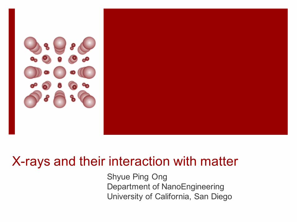
Superposition of waves¡ Phase difference
¡ Phase-shifted wave can be represented as
¡ When two phase-shifted waves are superimposed, we have:
¡ When phase difference is an odd multiple of 180° (= π radians), the sum vanishes (destructive interference).
¡ Constructive interference occurs when the two waves are in phase , i.e., phase difference is a multiple of 360° (= 2π radians)
NANO 106 - Crystallography of Materials by Shyue Ping Ong - Lecture 12
18
φ = 2π Δxλ
Acos(2π xλ)+ Acos(2π x
λ+φ) = 2Acos(2π x
λ+φ2)cos(φ
2)
Acos(2π xλ+φ)

Scattering of X-rays by lattice planes
¡ Incident X-ray at an angle to planes of atoms
¡ Some X-rays are refracted, while others are reflected (as shown by 1’ and 2’)
¡ Ray 2 has travelled an additional distance of O’P + O’Q = 2d sinΘ
¡ For constructive interference, the two waves must have a phase difference that is a multiple of 2π.
¡ This means that
NANO 106 - Crystallography of Materials by Shyue Ping Ong - Lecture 12
19
A1(x) = Acos(2πxλ)
A2 (x) = Acos(2πx + 2d sinθ
λ) = Acos(2π x
λ+ 2π 2d sinθ
λ)
2d sinθ = nλ where n is an integer.
Bragg equation

Bragg Equation
¡ Constructive interference from a set of consecutive parallel planes can only occur for certain angles θ (the Bragg angle), and that θ is determined by both the X-ray wavelength and the interplanar spacing.
¡ Knowing the wavelength, a measurement of the Bragg angle can provide a direct measurement of the interplanar spacing, and if we repeat this measurement for many different sets of planes, we can ultimately determine the dimensions of the unit cell.
¡ n defines the order of the diffraction process. If 2d sin θ = 2λ, then the diffracted beam is known as a second-order beam, or, in general, as the nth-order beam.
NANO 106 - Crystallography of Materials by Shyue Ping Ong - Lecture 12
20
2d sinθ = nλ where n is an integer.
Bragg angle

Parallel planes and the Bragg Equation
¡ Writing the Bragg equation as
¡ Recall from the first part of the course that the interlayer spacing for the planes (hkl) is given by
¡ d/n therefore represents the spacing for the planes (nh nk nl).
¡ We can therefore rewrite the Bragg equation as
¡ Note that in this form, you must distinguish between set of planes with different spacing, i.e., (100) is distinct from (200).
NANO 106 - Crystallography of Materials by Shyue Ping Ong - Lecture 12
21
2 dnsinθ = λ
dhkl =1ghkl
2dhkl sinθ = λ

Example: Cu¡ FCC structure with lattice parameter a = 0.36148nm.
NANO 106 - Crystallography of Materials by Shyue Ping Ong - Lecture 13
22
Blackboard

Example: Cu contd.¡ For Cu Kα radiation,
NANO 106 - Crystallography of Materials by Shyue Ping Ong - Lecture 13
23
Angle between incident and diffracted beam
Important note:1. The Bragg condition is a
necessary, but not sufficient condition for an observable diffraction beam
Blackboard

Bragg’s law in reciprocal space¡ Recall that X-rays can be characterized
by the wave vector k, which is in reciprocal space:
¡ Consider an X-ray incident on a lattice plane (hkl). Let us define the origin O as the end-point of the incident beam and the start point of the diffracted beam.
¡ Bragg equation =>
NANO 106 - Crystallography of Materials by Shyue Ping Ong - Lecture 13
24
Ae2πik⋅r
OG = k sinθ + !k sinθ = 2sinθλ
OG =1d= ghkl
Reciprocal version of Bragg equation: A diffracted beam with wave vector k’ will be present if and only if the endpoint of the vector k + g lies on the Ewald sphere (the Bragg orientation).
Radius 1/λ

2D Example: Orthorhombic lattice¡ Consider reciprocal lattice for an orthorhombic crystal below. How do
we find the Bragg condition for the (120) planes?
NANO 106 - Crystallography of Materials by Shyue Ping Ong - Lecture 13
25
110
100
110
120
010
O
010
020
Circles with radius 1/λ
k1
k1!
k2k2!
100

2D Example 2: Orthorhombic lattice
¡What if we want both the (120) and to be in the Bragg orientation?
NANO 106 - Crystallography of Materials by Shyue Ping Ong - Lecture 13
26
100
This can only be satisfied for one particular wavelength!

Diffraction in 3D¡ In 3D, the Bragg condition for a plane is satisfied
on a conical surface
NANO 106 - Crystallography of Materials by Shyue Ping Ong - Lecture 13
27

Limiting sphere¡ Bragg equation
¡ Hence, diffraction can only occur for reciprocal lattice points that lie within a sphere with radius
¡ If incident beam (or crystal) is rotated around, all lattice points within limiting sphere will at some point be in the Bragg orientation. Each point will coincide with the Ewald sphere exactly twice.
NANO 106 - Crystallography of Materials by Shyue Ping Ong - Lecture 13
28
sinθ = λ2d
≤1
⇒ λ ≤ 2d⇒ 1d≤2λ⇒ g ≤ 2 k
2 k

Experimental X-ray diffraction techniques¡ In most experimental setups, the X-ray tube is stationary and the beam is
collimated to produce a parallel incident beam. This incident beam can then be represented by a wave vector k. The position of the Ewald sphere does not change.
¡ In general, most lattice points will not be on the Ewald sphere for an arbitrary crystal orientation. Most experimental techniques rotate the crystal so that each reciprocal lattice point, at some point, crosses the Ewald sphere.
NANO 106 - Crystallography of Materials by Shyue Ping Ong - Lecture 13
29

X-ray powder diffractometer
¡ Polycrystalline sample – randomly oriented grains with all possible lattice planes
¡ Sample platform rotated at ω and detector at 2ω (maintaining Bragg condition)
¡ Typical experiment to identify structure involve doing a diffraction, followed by comparison with one of the several large online databases (e.g., the Powder Diffraction Files)
NANO 106 - Crystallography of Materials by Shyue Ping Ong - Lecture 13
30

Practical example
NANO 106 - Crystallography of Materials by Shyue Ping Ong - Lecture 13
31
¡X-ray diffractometer
Exterior Interior
X-ray Generator
Sample Holder
X-ray Detector

Practical Example: TaC (Fm-3m)¡Powder Diffraction Files (PDFs) and Peak
Matching
NANO 106 - Crystallography of Materials by Shyue Ping Ong - Lecture 13
32
A typical PDF card layout from ICDD Actual laboratory XRD results