Embed Size (px)
Citation preview

Reflection of Light Reflection of Light
Note: Both the angle of incident and angle of reflection must be measured from the
normal. Laws of Reflection
1. The law of reflection state that
a. The angle of incidence is equal to the angle of reflection; the ray
leaves the surface at the same angle as it arrives.
b. The incident ray, the reflected ray and the normal all lie in the same
plane; all three could be drawn on the same flat piece of paper
Type of Mirror

Plane Mirror
(Reflection of light on a plane mirror)
Plane Mirror
Images in plane mirrors
1. Figure to the right shows how, by reflecting light, a plane mirror forms an image of a point source of light such as a small light bulb.
2. The image forms in a mirror is
a. Upright
b. Virtual
c. Laterally inverted
d. Same size as the object

Steps to draw a ray diagram for an image in a plane mirror
Step 1
( Draw the virtual image. Distance of object = Distance of image )
Step 2
( Draw 2 reflected rays, one from the image to the top of the eye and the other one from the
image from the bottom of the eye. )
Step 3
( Draw the respective incident rays for the reflected rays you draw in step 2. )

Curved Mirror Curved Mirror
1. A curve is part of a circle. Therefore
a. the centre of the circle will also be the centre of the curve and is
called the centre of curvature, and
b. the radius of the circle will be equal to the radius of the curve, called
the curvature radius.
Important Terms
All rays parallel to the principle axis will focus at F

Centre of
curvature, C
The geometric centre of a hollow sphere of which the concave or
convex mirror is a part.
Pole of mirror, P The centre point on the curved mirror.
Principal axis A line which passes through the centre of curvature, C and the pole of a curved mirror, P.
Radius of
curvature, r
Distance between the pole, P and the centre of curvature, C.
Principal focus, F A point through which all rays travelling parallel to the principal
axis converge to or appear to diverge from after reflection by the mirror.
Focal length, f The distance between the principal focus, F and the pole of the
curved mirror, P.
Aperture of mirror The portion of the surface of the mirror that reflects light.
Object distance, u Distance of object from the pole of the mirror, P.
Image distance, v Distance of image from the pole of the mirror,
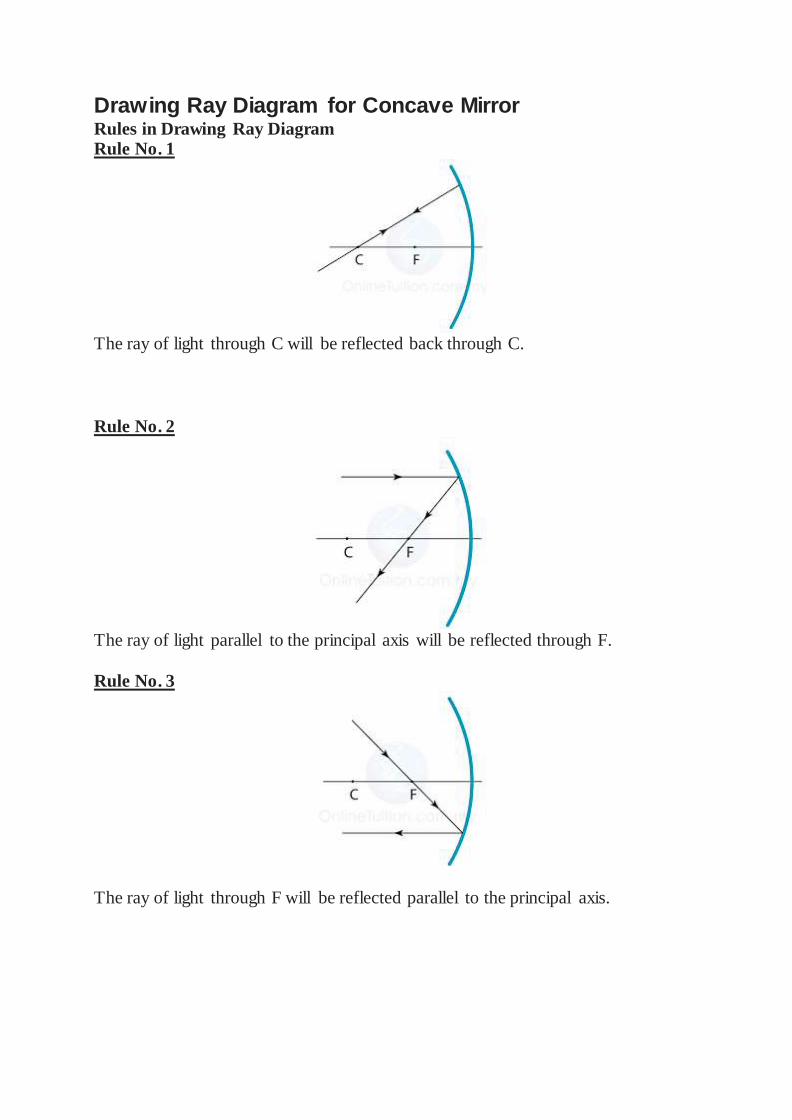
Drawing Ray Diagram for Concave Mirror Rules in Drawing Ray Diagram Rule No. 1
The ray of light through C will be reflected back through C.
Rule No. 2
The ray of light parallel to the principal axis will be reflected through F.
Rule No. 3
The ray of light through F will be reflected parallel to the principal axis.

Drawing Ray Diagram of a Convex Mirror Rules in Drawing Ray Diagram Rule No. 1
A ray towards C is reflected back along its own path.
Rule No. 2
A ray parallel to the principal axis is reflected as if it came from F.
Rule No. 3

A ray towards F is reflected parallel to the principal axis.
Finding the Position and Size of the Image
1. Any two rays are sufficient to fix the position and size of the image. Look
for the point where the rays cross after reflection from the mirror.
2. The interception of the two rays is the focus of the ray.
Example
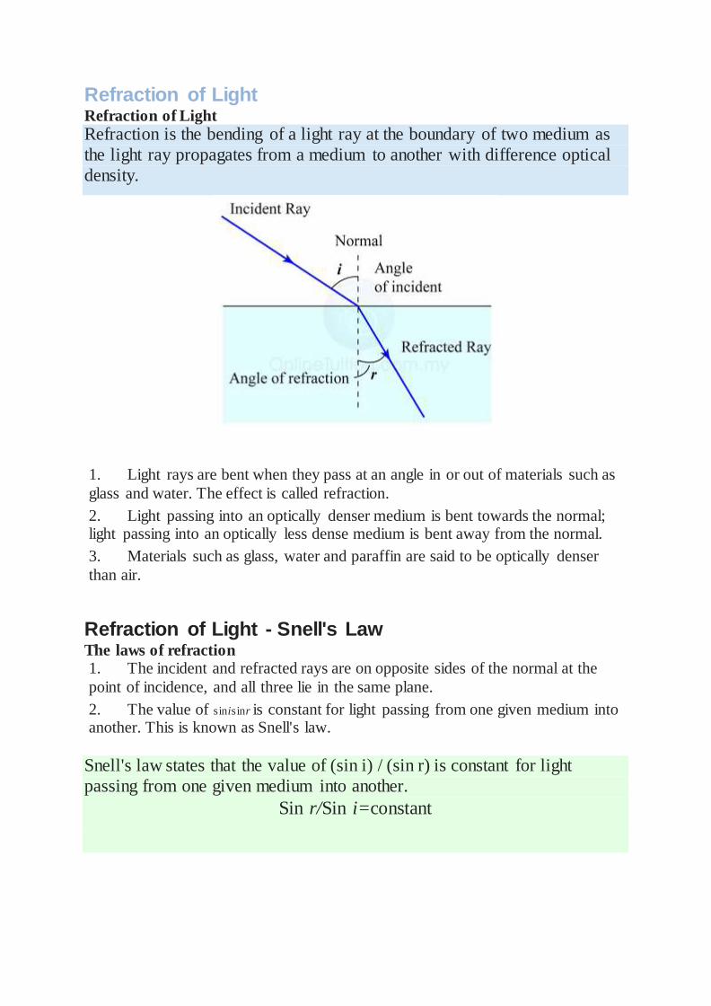
Refraction of Light Refraction of Light
Refraction is the bending of a light ray at the boundary of two medium as
the light ray propagates from a medium to another with difference optical
density.
1. Light rays are bent when they pass at an angle in or out of materials such as
glass and water. The effect is called refraction.
2. Light passing into an optically denser medium is bent towards the normal; light passing into an optically less dense medium is bent away from the normal.
3. Materials such as glass, water and paraffin are said to be optically denser
than air.
Refraction of Light - Snell's Law The laws of refraction 1. The incident and refracted rays are on opposite sides of the normal at the
point of incidence, and all three lie in the same plane.
2. The value of sinisinr is constant for light passing from one given medium into another. This is known as Snell's law.
Snell's law states that the value of (sin i) / (sin r) is constant for light
passing from one given medium into another.
Sin r/Sin i=constant

Refractive Index Refractive index
1. The value of sin i/sin r is called the refractive index of the medium and it
gives you an indication of its light-bending ability.
n=sin i/sin r
n= refractive index
2. In SPM, when we say “refractive index”, what we mean is the absolute refractive index of a substance. The absolute refractive index of a substance is the
refractive index where light ray travels from vacuum (or air) into the substance.
Refractive index = speed of light in vacuum/speed of light in medium
or
n=c/v
( Note that the greater the refractive index of a medium, the lower is the speed of
light. The more light is slowed, the more it is bent. )
Real and Apparent Depth
1. The bending of light can give you a false impression of depth.
2. Figure to the left shows two rays of light leaving a point on the bottom of a
swimming pool.
3. The rays are refracted as they leave the water. To the observer, the rays
seem to come from a higher position, and the bottom looks closer to the surface
than it really is.

4. The real depth of the water and its apparent depth are marked on the
diagram. These are related to the refractive index of the water by the following
equation:
Refractive index = real depth/apparent depth
or
n=D/d
Summary:
Refractive index
n=sin i/sin r
n=D/d
n=c/v

Natural Phenomenon due to Refraction of Light Bending of Object in a Glass
A straw in a glass with water looks bended or broken. This is due to refraction of
light
Shallower Swimming Pool
A swimming pool appears shallower than it actual is. This is because the light from
the pool is refracted away from the normal when moving from water to the air.
Atmospheric Refraction and Setting sun
The setting sun looks oval in shape because the light from the sun is refracted at
different rate when passes through the atmosphere.

Twinkling Star
The light of stars is refracted when passes through different region in the atmosphere. The angle of refraction varies a little from time to time. As a result, the
stars look twinkling.
Total Internal Reflection and Critical Angle Total Internal Reflection and the Critical Angle
1. In figure (a) above, the light ray is refracted away from the normal when
moving from denser medium to less dense medium.
2. Figure (b) shows that, at a specific angle, the light ray is refracted 90o from
the normal. It is refracted so much that it is only just able to leave the water. In
such condition, the incident angle is called the critical angle.
3. The critical angle is the angle of incident in an optically denser medium for
which the angle of refraction is 90°.
4. In figure (c), the light ray strikes the surface at an angle of incidence greater
than c. There is no refracted ray; the surface of the water acts like a perfect mirror,
and the ray is said to have been totally internally reflected.

The Equation Relates the Critical angle (c) with the Refractive Index The critical angle can be calculated by using the following equation:
Requirements for Total Internal Reflection to occur.
1. The light ray must propagate from an optically denser medium to an
optically less dense medium.
2. The angle of incident must exceed the critical angle.

Phenomena Related to Total Internal Reflection Mirage
1. The occurrence of mirage can be explained as follows.
2. The air on the road surface consists of many layers. On a hot day, the air
near the ground has a low specific heat capacity, hence the temperature increase
faster.
3. The hot air becomes less dense than the cold air higher up.

4. A ray of light originated from the sky is refracted away from the normal as
the light is travel from denser to less dense air.
5. As the air passes through the lower layers, the angle of incidence increases
and the refracted ray is getting further away from the normal.
6. Finally, at a layer of air close to the road surface, the angle incidence
exceeds the critical angle. Total internal occurs and the light ray bends upward
towards the eye of the observer.
7. The observer sees the image of the sky and the clouds on the surface of the
road as a pool of water.
Rain Bow
1. The spectrum of a rainbow is caused by total internal reflection in the water
droplets.
2. Different angles of total internal reflection produces different colours.

Lenses Lenses 1. There are 2 types of lenses, namely the
a. Convex lens
b. Concave lens
2. Convex lenses are thickest through the middle, concave lenses are thickest around the edge, but several variations on these basic shapes are possible, as
shown in figure 1.
3. Light rays passing through a convex or converging lens are bent towards the principal axis, whereas rays passing through a concave or diverging lens are bent
away from the principal axis.
Figure 1: Convex Lenses
Figure 2: Concave Lenses
Important Terms
Optical centre, P Light passing through the central block emerges in the
same direction as it arrives because the faces of this block are parallel. P marks the optical centre of the
lens.
Principle Axis The principle axis of a lens is the line joining the centres of of curvature of its surfaces.
Principle focus, F The principle focus of a lens is the point on the priciple axis to which all rays originally parallel and close to the
axis converge, or from which they diverge, after passing through the lens.
Focal length, f The focal length of a lens is the distance between the
optical centre an the principle focus.
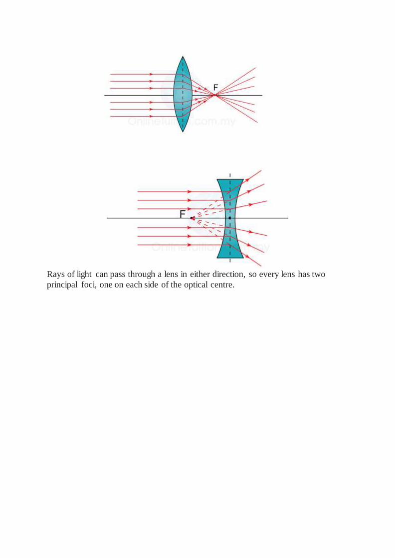
Rays of light can pass through a lens in either direction, so every lens has two
principal foci, one on each side of the optical centre.

Power of Lenses The Power of a Lens 1. The power of a lens is defined as the reciprocal of the focal length in unit
meter.
P=1/f
Important Note: f is in meter
2. The unit of power is diopter (D).
3. The relationship of the power with the thickness and types of lens are shown in the
diagram below.
Lens Power of the Lens
Converging (Convex) Positive
Diverging (Concave) Negative
Thick, with short focal length. High
Thin, with long focal length. Low
Thinner – Lower Power – Longer Focal Length
Thicker – Higher Power – Shorter Focal Length

Example:
The power of a lens is labeled as +5D. What is the focal length of the lens (in cm)?
Is this a concave lens or a convex lens?
Answer:
P=1/f
(+5)=1/f
f=1/5=0.2m = 20cm
The power of the lens is positive. This is a convex lens.
Convex Lens
Rules for Drawing Ray Diagram for Convex Lenses 1. A light ray passes through the optical centre of the lens will not be refracted.
2. A light ray parallel to the principle axis of the lens will be refracted passes
through the principle focus.
3. A light ray passes through principle focus will be refracted parallel to the principle axis.

Characteristics of the Image Formed by a Convex Lens Characteristics of the Image Formed by a Convex Lens
1. As with a curved mirror, the position and size of an image can be found by
drawing a ray diagram.
2. Any two of the following three rays are sufficient to fix the position and
size of the image.
3. The characteristics, position and size of the image formed by a convex lens
depends on the object distance (u) relative to the focal length (f)
Position of Object: u > 2f
Characteristics of the Image: Real, inverted, diminish
Distance of image: v < 2f
Position of Object: u = 2f

Characteristics of the Image: Real, inverted, same size
Distance of image: v = 2f
Position of Object: f < u < 2f
Characteristics of the Image: Real, inverted, magnified
Distance of image: v > 2f
Position of Object: u = f
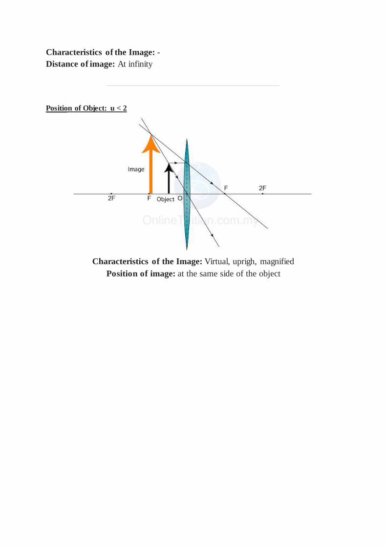
Characteristics of the Image: -
Distance of image: At infinity
Position of Object: u < 2
Characteristics of the Image: Virtual, uprigh, magnified
Position of image: at the same side of the object
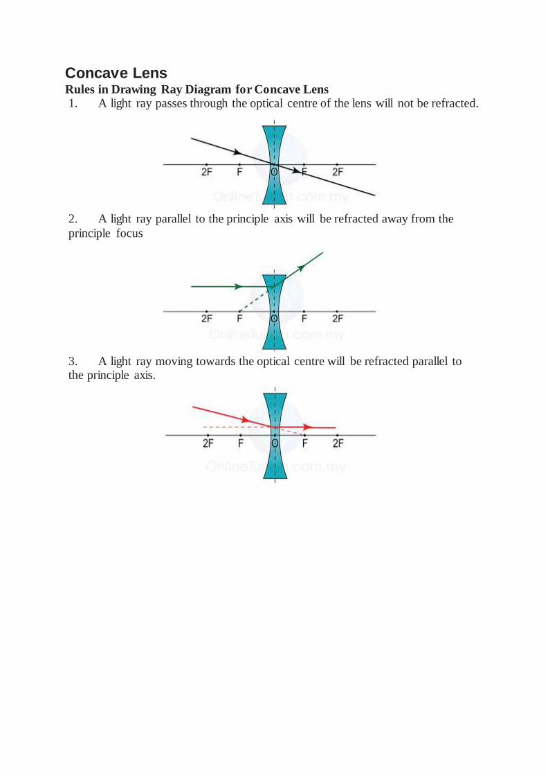
Concave Lens Rules in Drawing Ray Diagram for Concave Lens 1. A light ray passes through the optical centre of the lens will not be refracted.
2. A light ray parallel to the principle axis will be refracted away from the
principle focus
3. A light ray moving towards the optical centre will be refracted parallel to the principle axis.

Characteristics of the Image Formed by a Concave Lens
1. The image formed by a concave lens always has the same characteristics,
namely
a. virtual
b. upright
c. diminish
2. Figure below shows the ray diagram for the formation of image of a
concave lens.

The Lens Equation The Lens Equation 1. The following is the lens equation that relates the object distance (u), image
distance (v) and the focal length.
1/u+1/v=1/f
2. When using the lens equation to solve problem, it's important to note the
positive negative sign of u, v and f.
3. Table below give the conventional symbol and sign for u, v and f.
Positif Negatif
u Real object Virtual object
v Real image Virtual image
f Convex lens Concave lens
Linear Magnification
The linear magnification is a quantity that indicates the ratio of the height of the image to the height of the object.
m=v/u=hi/ho
m = linear magnification
u = distance of object
v = distance of image
hi = heigth of image ho = heigth of object


Magnifying Glass Magnifying Glass
1. Magnifying glass is also known as simple microscope.
2. A magnifying glass is a single convex lens with short focal length.
3. The image formed is
a. virtual,
b. magnified
c. upright
4. A magnifying glass enlarges the image of an object by increasing the virtual
angle at the eye when the object is viewed.
Angular magnitude and apparent size
1. The angular magnitude of an object is the virtual angle at the eye. It is the
angle the object subtends at the eye.
2. This angle determines the size of the image (apparent size) formed on the retina and hence governs the apparent size of the object

Optical Instruments - Camera Camera
Functions
Convex lens To focus the light of an object onto the film so that a sharp image can
be produced.
Diaphragm To control the size of the aperture and hence control the amount of
light move into the camera.
Focusing Ring To adjust the distance between the lens and the film so that the image is sharply focus on the film.
Film 1. Acts as a screen for the image to form onto it.
2. Chemical on it will react when exposed to light and produce a
photograph.
Shutter Open when picture is taken to allow light move onto the film. The shutter speed is the length of time when the shutter is open. It
control the amount of light move onto the film.
Aperture Open when picture is taken to allow light move onto the film.
The shutter speed is the length of time when the shutter is open. It control the amount of light move onto the film.
Note:
1. The film, which is normally kept in total darkness, contains a light-sensitive
chemical called silver bromide.
2. When you press the camera button, a shutter in front of the film opens then
shuts again, exposing the film to light for a brief moment only.
3. Different intensities and colours of light across the image cause varying
chemical changes in the film, which can later be developed, 'fixed', and used in
printing a photograph.
4. The image formed on the film is
a. Real
b. Inverted
c. Smaller than the object.
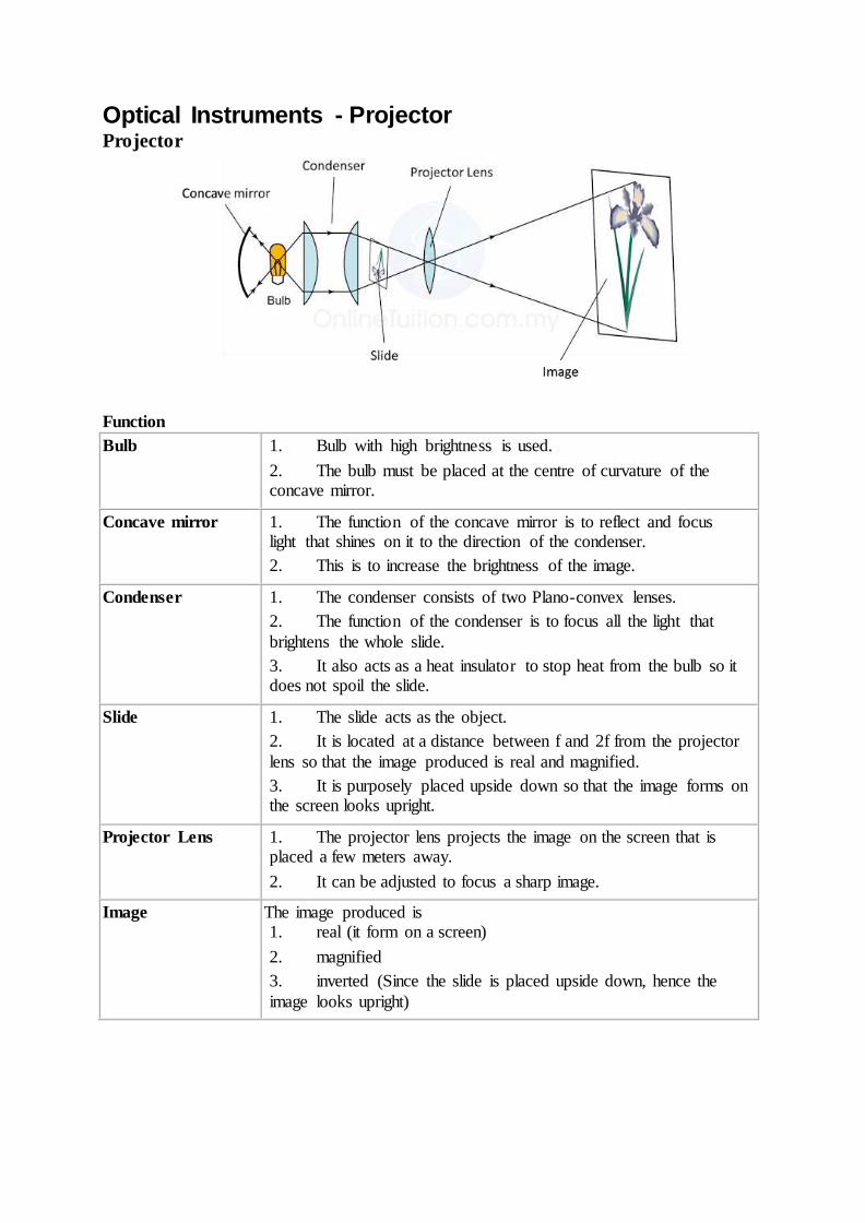
Optical Instruments - Projector Projector
Function
Bulb 1. Bulb with high brightness is used.
2. The bulb must be placed at the centre of curvature of the concave mirror.
Concave mirror 1. The function of the concave mirror is to reflect and focus light that shines on it to the direction of the condenser.
2. This is to increase the brightness of the image.
Condenser 1. The condenser consists of two Plano-convex lenses.
2. The function of the condenser is to focus all the light that
brightens the whole slide.
3. It also acts as a heat insulator to stop heat from the bulb so it does not spoil the slide.
Slide 1. The slide acts as the object.
2. It is located at a distance between f and 2f from the projector
lens so that the image produced is real and magnified.
3. It is purposely placed upside down so that the image forms on the screen looks upright.
Projector Lens 1. The projector lens projects the image on the screen that is placed a few meters away.
2. It can be adjusted to focus a sharp image.
Image The image produced is 1. real (it form on a screen)
2. magnified
3. inverted (Since the slide is placed upside down, hence the
image looks upright)

Optical Instruments - Astronomical Telescope Astronomical Telescope
Astronomical Telescope
Objective lens Lower power
Eye lens Higher power
Position of the object At infinity
Nature of the image, I1 Real, inverted and magnified
Position of the image,
I1. At the principle focus of object lens, fo.
Nature of the image, I2 Virtual, inverted and smaller in size.
Distance in between the
two lens 1. The distance between the object lens and the eye
lens in a compound microscope is equal to the sum
of the focal length (fo + fe). 2. If the distance between both lenses are bigger than
(fo + fe), no image can be seen.
Magnification of the
compound microscope. m = Focal length of the object lens, fo
Focal length of the eye lens, fm
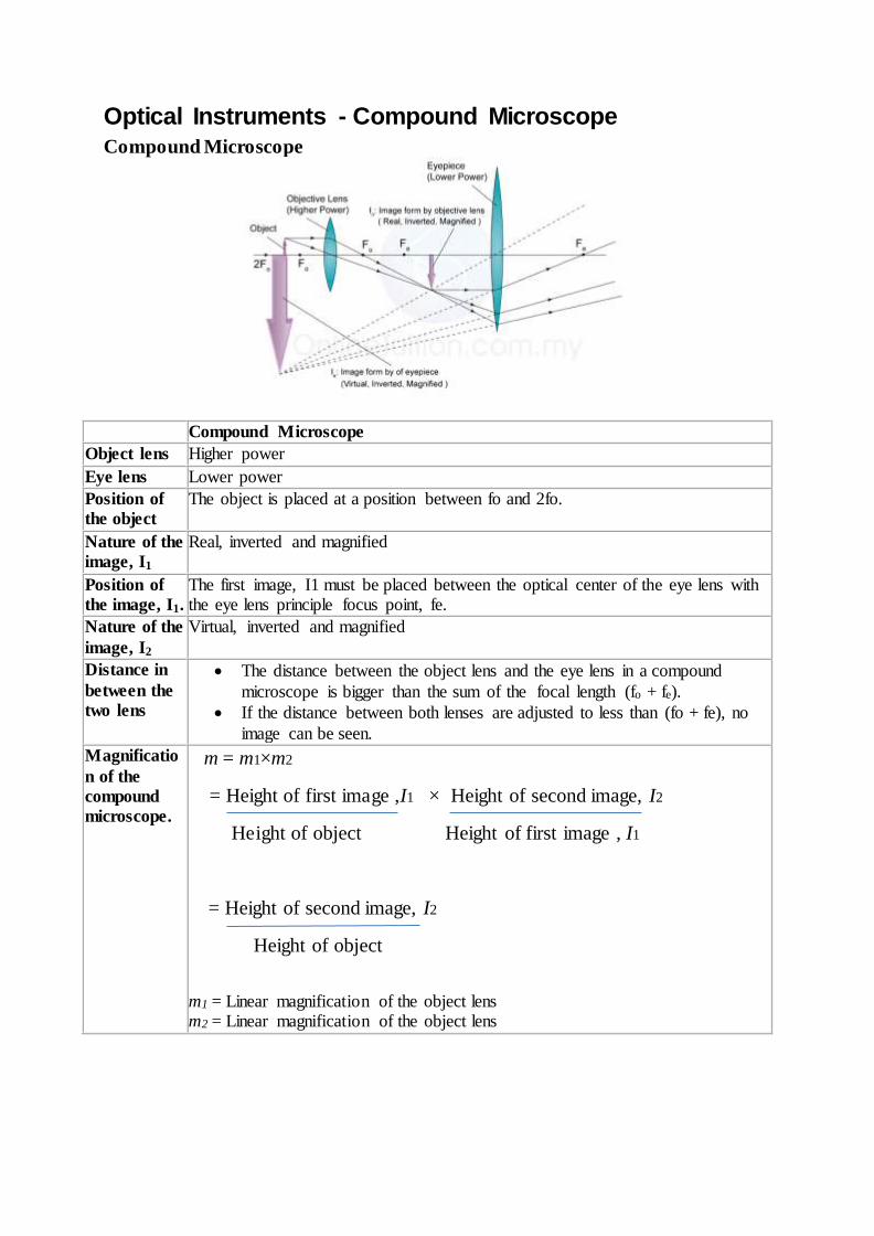
Optical Instruments - Compound Microscope
Compound Microscope
Compound Microscope
Object lens Higher power
Eye lens Lower power
Position of
the object The object is placed at a position between fo and 2fo.
Nature of the
image, I1 Real, inverted and magnified
Position of
the image, I1. The first image, I1 must be placed between the optical center of the eye lens with the eye lens principle focus point, fe.
Nature of the
image, I2
Virtual, inverted and magnified
Distance in
between the
two lens
The distance between the object lens and the eye lens in a compound
microscope is bigger than the sum of the focal length (fo + fe).
If the distance between both lenses are adjusted to less than (fo + fe), no
image can be seen.
Magnificatio
n of the
compound
microscope.
m = m1×m2
= Height of first image ,I1 × Height of second image, I2
Height of object Height of first image , I1
= Height of second image, I2
Height of object
m1 = Linear magnification of the object lens m2 = Linear magnification of the object lens