Embed Size (px)
Citation preview
Delft Design Guide | Part 1 | Engineering Models of Product Design – 1.4
1.4 Engineering Models of Product Design
Models of the design process have been developed since
the early nineteen-sixties. In engineering design, this
development has converged to what might be called a
consensus model. Typical examples of this model are
the model of Pahl and Beitz and the VDI-model (Verein
Deutscher Ingenieure). These models are also called
phase-models or procedural models.
The engineering models are fundamentally derived
from the way in which engineering design problems are
conventionally perceived and modelled. Products are
seen as technical systems that transform energy, material
and information. The functional behaviour of a technical
system is fully determined by physical principles and can
be described by physical laws. The engineering design
problem is to find and define the geometry and materials
of the system in such a way that the required prescribed
physical behaviour is realised in the most effective and
efficient way.
Engineering models are based on the idea that a design-in-
the-making can exist in three different ways:
1 As a function structure; this is a representation of the
intended behaviour (the functions) of a product and its
parts.
2 As a solution principle; this defines the working principle,
or mode of action, of a product or a part thereof. It
specifies (in generic terms) the function carriers or ‘organs’
of which a product should be built up, to fulfil its internal
and external functions.
How can you structure engineering design processes?
manual power
mixer
whipping cream (liquid)
bowl
sugar
arm power
water
force
force
sound
sound
heatsoundwhipped cream
whipped cream
dishwater
clean mixer
pressure for stability
sound and heat
taking mixerchanging mixer’s
mode
changing beater position
tastingcream
tranfering human power into movement
of beater(s)
pouring whipping cream into bowl
adding sugar
reading instructions
testing cream density
removing excess cream of beaters
cleaning the beaters
drying beaters
storing mixer
transfering arm power into rotation
static handle
dynamic handle
gearbox
beater movement
transfering to rotating movement
transfering to lineair movement
or
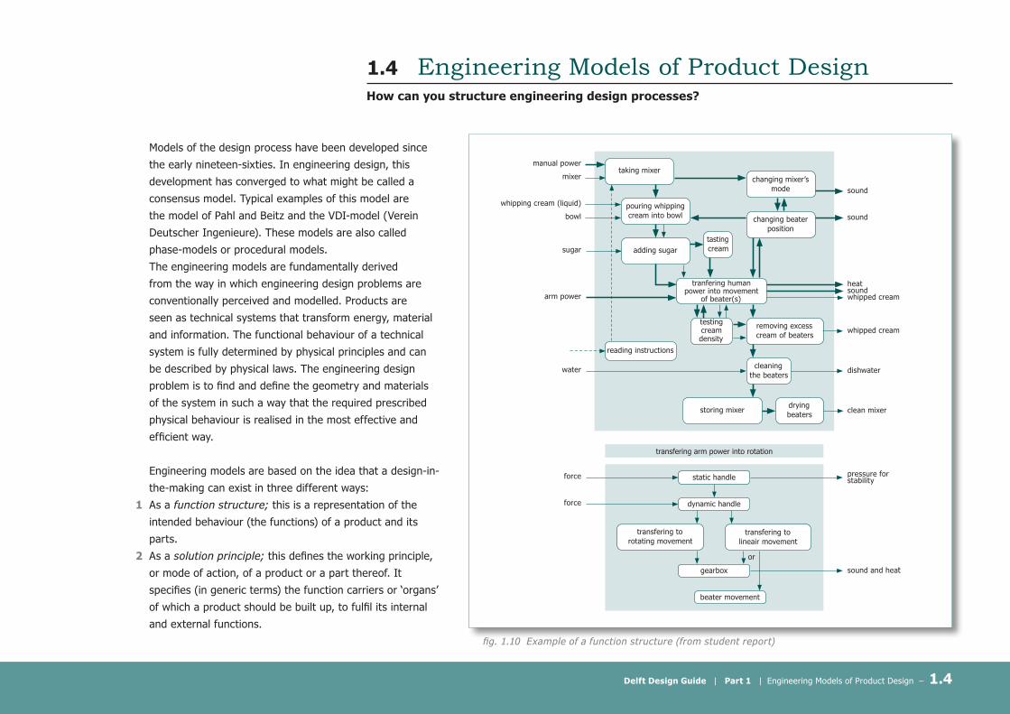
fig. 1.10 Example of a function structure (from student report)
Delft Design Guide | Part 1 | Engineering Models of Product Design – 1.4
3 As an embodied design; this is a design in the
more usual meaning of the word. It is a description,
usually as a drawing, of the geometrical and physico-
chemical form of a product and its parts.
The Function Structure
In a function structure (see figure 1.10), the product
and its components and parts are represented by
their functions. It is an abstract representation that
does not refer to concrete shape and material of the
physical parts of the system.
The function structure is an important methodological
tool; it provides an aid for thinking about the mode
of action of a product, without enforcing premature
decisions on its embodiment.
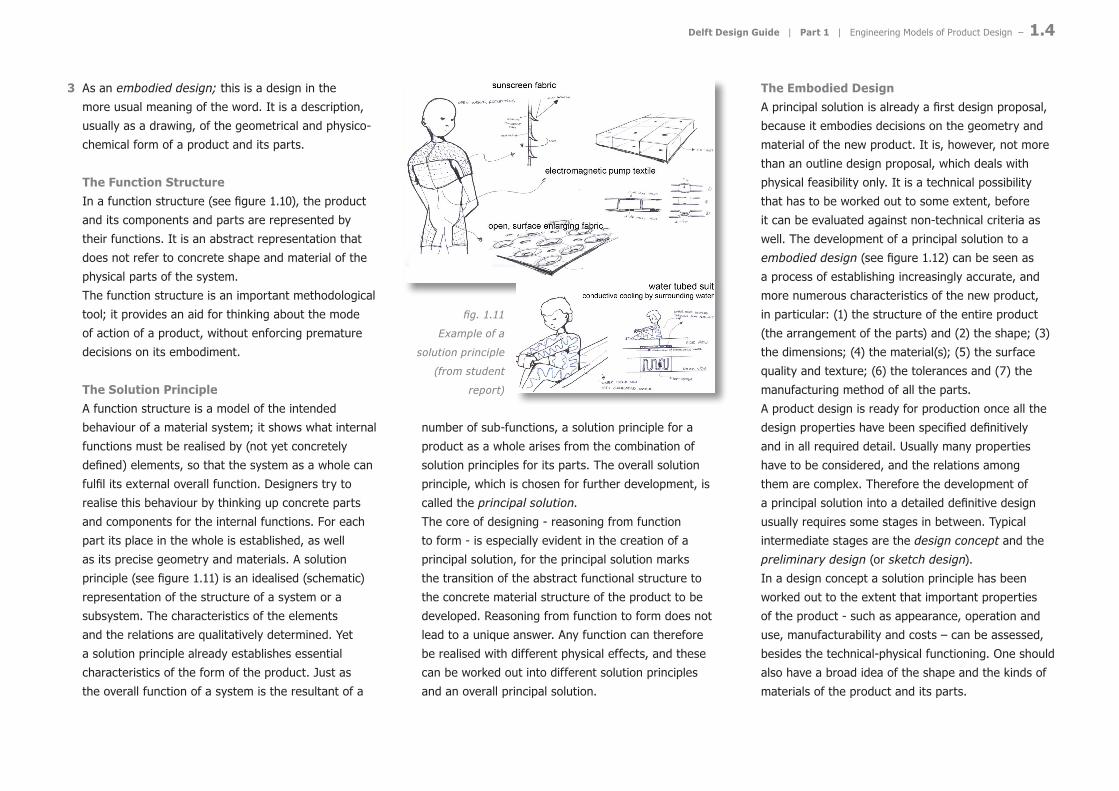
The Solution Principle
A function structure is a model of the intended
behaviour of a material system; it shows what internal
functions must be realised by (not yet concretely
defined) elements, so that the system as a whole can
fulfil its external overall function. Designers try to
realise this behaviour by thinking up concrete parts
and components for the internal functions. For each
part its place in the whole is established, as well
as its precise geometry and materials. A solution
principle (see figure 1.11) is an idealised (schematic)
representation of the structure of a system or a
subsystem. The characteristics of the elements
and the relations are qualitatively determined. Yet
a solution principle already establishes essential
characteristics of the form of the product. Just as
the overall function of a system is the resultant of a
number of sub-functions, a solution principle for a
product as a whole arises from the combination of
solution principles for its parts. The overall solution
principle, which is chosen for further development, is
called the principal solution.
The core of designing - reasoning from function
to form - is especially evident in the creation of a
principal solution, for the principal solution marks
the transition of the abstract functional structure to
the concrete material structure of the product to be
developed. Reasoning from function to form does not
lead to a unique answer. Any function can therefore
be realised with different physical effects, and these
can be worked out into different solution principles
and an overall principal solution.
The Embodied Design
A principal solution is already a first design proposal,
because it embodies decisions on the geometry and
material of the new product. It is, however, not more
than an outline design proposal, which deals with
physical feasibility only. It is a technical possibility
that has to be worked out to some extent, before
it can be evaluated against non-technical criteria as
well. The development of a principal solution to a
embodied design (see figure 1.12) can be seen as
a process of establishing increasingly accurate, and
more numerous characteristics of the new product,
in particular: (1) the structure of the entire product
(the arrangement of the parts) and (2) the shape; (3)
the dimensions; (4) the material(s); (5) the surface
quality and texture; (6) the tolerances and (7) the
manufacturing method of all the parts.
A product design is ready for production once all the
design properties have been specified definitively
and in all required detail. Usually many properties
have to be considered, and the relations among
them are complex. Therefore the development of
a principal solution into a detailed definitive design
usually requires some stages in between. Typical
intermediate stages are the design concept and the
preliminary design (or sketch design).
In a design concept a solution principle has been
worked out to the extent that important properties
of the product - such as appearance, operation and
use, manufacturability and costs – can be assessed,
besides the technical-physical functioning. One should
also have a broad idea of the shape and the kinds of
materials of the product and its parts.
BEAT TH
E HEAT appendices ���
industrial design engineering Willem
ijn Verduijn
fig. 1.11
Example of a
solution principle
(from student
report)

Delft Design Guide | Part 1 | Engineering Models of Product Design – 1.4
A preliminary design is the following stage and also
the last stage before the definitive design. It is
characteristic of this stage that the layout and shape
and main dimensions have been established for at
least the key parts and components of the product,
and the materials and manufacturing techniques have
been determined.
The modes of existence of a design proposal as
described above, enable designers to explicate their
thoughts about a design, and to judge and further
develop them. Often there corresponds a more or
���
B
EAT
THE
HEA
T ap
pend
ices
in
dust
rial d
esig
n en
gine
erin
g W
illem
ijn V
erdu
ijn ��.� CONCEPT GENERATION
With this focus in mind, several concepts have been generated. A selection is shown here. less usual form of representation to each stage, such
as flow diagrams for function structures, diagrams
for solution principles, sketches for concepts, layout
drawings for preliminary designs and standardised
technical drawings for definitive designs. Such
documents mark a stage in the development of the
design and a phase in the design process.
The model of Pahl & BeitzA typical example of this ‘consensus model’ is the
model of Pahl & Beitz (figure 1.13). Their model has
four phases:
• clarification of the task (‘Aufgabe klären’)
• conceptual design (‘konzipieren’)
• embodiment design (‘entwerfen’)
• detail design (‘ausarbeiten’)
Broadly speaking, the phases involve the following
activities:
Clarification of the task
In this phase the problem, handed over to the designer
by the product planning department or an external
client, is analysed, and information on the problem
is collected. Based upon that information a design
specification (or programme of requirements) is
drawn up. The specification defines the functions and
properties that are required for the new product, as
well as the constraints placed upon the solution and
the design process itself, such as standards and date
of completion.
The specification directs the work in all other phases
of the design process. Work done in later phases
may change ones understanding of the problem and
new information may become available. Therefore
modification and refinement of the initial specification
should be undertaken regularly. This is indicated by
the feedback loops in the models.
Conceptual design
Given the specification, broad solutions are to be
generated and evaluated, that provide for a suitable
point of departure for embodiment design and detail
design. Such broad solutions are called concepts
(Pahl & Beitz) or schemes (French). Normally they are
documented as diagrams or sketches.
The conceptual phase starts with determining the
overall function and important sub functions to be
fulfilled and establishing their interrelationships
(function structure). Next solution principles
(‘Lösungsprinzipien’), also called working principles
(‘Wirkprinzipien’), for sub-functions or sub-problems
are generated and integrated into overall solutions,
in accordance with the function structure. Such
a combination of solution principles has been
called a principal solution (‘Prinzipielle Lösung’). A
principal solution defines those physical-technical
characteristics of a product, that are essential for its
functioning.
However, the choice for a particular principal solution
is not to be based upon technical criteria only. Criteria
relating to use, appearance, production, costs and
others, must also be taken into account. To that end
principal solutions have to be worked up into concept
variants that show already part of the embodiment
of the principle. A concept, or scheme, should be
carried to a point ‘where the means of performing
fig. 1.12 Example of embodied design (from student report)

Delft Design Guide | Part 1 | Engineering Models of Product Design – 1.4
each major function has been fixed, as have
the spatial and structural relationships of the
principal components.
A scheme should have been sufficiently
worked out in detail for it to be possible to
supply approximate costs, weights and overall
dimensions, and the feasibility should have
been assured as far as circumstances allow.
A scheme should be relatively explicit about
special features or components, but need not
go into much detail over established practice.
Conceptual design is commonly seen to be
the most important phase of the design
process, because the decisions made here,
will strongly bear upon all subsequent phases
of the design process. A weak concept can
never be turned into an optimum detailed
design, so to speak.
Embodiment design
In this phase the chosen concept is
elaborated into a definitive design, also called
definitive layout. The definitive design defines
the arrangement (‘layout’) of assemblies,
components and parts, as well as their
geometrical shape, dimensions and materials
(‘form designs’).
Contrary to what the phrase ‘definitive’ may
suggest, the definitive design need not be
completely worked out into full detail. The
configuration of the product and the form
of the parts are to be developed up to the
point where the design of the product can be
tested against all major requirements of the
specification, preferably as a working model
or prototype.
The decisions to be taken about the layout
and form of the components and parts
are strongly interrelated. Therefore, more
than conceptual design, embodiment
design involves corrective cycles in which
analysis, synthesis, simulation and evaluation
constantly alternate and complement each
other. Embodiment design is essentially a
process of continuously refining a concept,
jumping from one sub-problem to another,
anticipating decisions still to be taken and
correcting earlier decisions in the light of the
current state of the design proposal. It proves
therefore difficult to draw up a detailed plan
of action for this phase, that holds in general.
In Pahl and Beitz’ model embodiment design
is subdivided into two stages. The first
stage is leading to a preliminary design, in
which the layout, form and material of the
principal function carriers are provisionally
determined. In this stage several alternative
embodiments of a concept are often worked
up in parallel in order to find the layout. In
the second stage, then, the best preliminary
task
clarify the taskelaborate the specification
identify essential problemsestablish function structuressearch for solution principles
combine and firm up into concept variantsevaluate against technical and economic criteria
develop preliminary layouts and form designsselect best preliminary layouts
refine and evaluatle against technical and economic criteria
optimise and complete form designscheck for errors and cost effectiveness
prepare the preliminary parts list and production documents
finalise detailscomplete detail drawings and production documents
check all documents
specifications
concept
preliminary design
definitive design
documentation
solution
info
rmat
ion:
ada
pt t
he s
peci
ficat
ion
upgr
ade
and
impr
ove
embo
dim
ent
desi
gn
optim
alis
atio
n of
the
layo
ut a
nd f
orm
s
deta
il de
sign
optim
alis
atio
n of
the
princ
iple
conc
eptu
al d
esig
ncl
arifi
catio
n of
the
tas
k
fig. 1.13
Phase model of the Product
Design Process by Pahl
and Beitz (Roozenburg and
Eekels, 1995)

Delft Design Guide | Part 1 | Engineering Models of Product Design – 1.4
design is elaborated, up to the point where all
major decisions about the layout and form of the
product are taken and tests of its functionality,
operation and use, appearance, consumer
preference, reliability, manufacturability and
cost can be carried out. Normally at the end of
this phase the design is represented by layout
drawings, made to scale and showing important
dimensions, and preliminary parts lists.
Detail design
In this final phase the geometrical shape,
dimensions, tolerances, surface properties and
materials of the product and all is individual parts
are fully specified and laid down in assembly
drawings, detail drawings and parts lists. Also
instructions for production, assembly, testing,
transport and operation, use, maintenance and
the like, have to be worked out now. All these
documents fall under the heading of the ‘product
documents’.
The VDI Model (Verein Deutscher Ingenieure)Of a more recent date than the model of Pahl
and Beitz is the Guideline VDI 2221, Systematic
Approach to the Design of Technical Systems
and Products. This guideline aims for a general
approach to design, which is applicable to a wide
variety of tasks including product design, and
transcends specific branches of industry.
To demonstrate its potential, examples are given
for mechanical engineering, process engineering,
precision engineering (mechatronics) and
software engineering. Yet, the ideas presented in
the guideline seem to be more closely associated
with mechanical engineering design.
The general approach is divided into seven
stages, correspondingly producing seven results
(figure 1.14). Either all or some of the stages are
to be completed, depending on the task at hand.
Individual stages can be combined into design
phases, in order to assist the overall planning and
management of the design process. It is stated
that the way stages are grouped into phases can
differ depending on the branch of industry or
company.
Apart from stage 4, in which a so-called
module structure (‘modulare struktur’) is to
be established, all stages and results can be
recognised in the Pahl and Beitz model as well.
The module structure takes more or less the
place of the concept in the Pahl and Beitz model.
The module structure specifies the division
of a principal solution into realisable parts,
components or assemblies, which has to be
undertaken before starting the process of defining
these modules in more concrete terms. Such a
breakdown is particularly important for complex
products, as it facilitates the distribution of design
effort in the phase of embodiment design.
task
divide into realisable solutions
further realisation
clarify and define the task1
determine functions and their structure2
search for solution principles and their combinations
3
4
develop layouts of key modules
5
complete overall layout6
prepare production and operating instructions7
specification
function structure
principal solution
module structure
preliminary design
definitive design
product documents
problem analysis
conceptual design
embodiem
ent design
detail design
fig. 1.14 Phase model of the Product Design Process by VDI
(Roozenburg and Eekels, 1995)

Delft Design Guide | Part 1 | Engineering Models of Product Design – 1.4
Some comments on phase-models
• First, it is stressed by all authors of phase-models
that sharp divisions between the phases cannot
be drawn, and that the stages and phases do not
necessarily follow rigidly one after the other. They are
often carried out iteratively, returning to preceding
ones, thus achieving a step-by-step optimisation.
• Second, a phase-model does not show the problem-
solving process, by which solutions for the design
problem are generated and refined; in each phase the
designer will go through the basic design cycle, often
more than once.
• Third, in each phase alternative solutions can be
thought up. Working out all solution variants through
all phases would lead to an explosion of the number
of possibilities to be studied. On the other hand,
restricting oneself to one track only within the
network of possibilities is dangerous, because, then,
the better or best alternatives may be overlooked.
One is therefore urged to diverge and converge in
each phase.
• Fourth, the models have been developed with the
designing of new, innovative technical systems in
mind. Therefore they pay (too) much attention to
the conceptual design phase, at the expense of the
phases of embodiment design and detailed design.
In practice many design projects can do without
inventing new technical principles, and start from
known, proven, concepts. However the phase models
offer little procedural advice concerning embodiment
and detail design. It has even been questioned
whether more detailed procedural models for these
phases may exist (but see the ‘Fish-Trap’ Model in
section 1.5)
• In phase-models the end of each phase can be taken
as a decision point. Herein lies the importance of
phase models. At the decision points you look back
on the work performed, and you weigh the results
obtained against the goals of the project. Phase
models therefore urge a regular evaluation of the
project: reject, do a step back, or continue to the
following phase.
References and further Reading
Roozenburg, N. and Eekels, J. (1995) Product Design:
Fundamentals and Methods, Chichester: Wiley, 1995,
pp. 94-114.
Roozenburg, N. and Eekels, J. (1998, 2nd ed.),
Productontwerpen: Structuur en Methoden, Utrecht: Lemma,
pp. 104-129.
VDI 222, Systematic Approach to the Design of Technical
Systems and Products. Düsseldorf, VDI, 1987.