Embed Size (px)
Citation preview
Page | 1
DEPARTMENT OF ELECTRICAL ENGINEERING
RAJASTHAN TECHNICAL UNIVERSITY, KOTA
A
SUMMER TRAINING REPORT
ON
NUCLEAR POWER PLANT
TAKEN AT
NUCLEAR POWER CORPORATION OF INDIA
LIMITED, RAWATBHATA (08 JUNE 2015 TO 07 AUGUST 2015)
Submitted To:- Submitted By:-
Dr. Mahendra Lalwani Lekha Raj Meena
(Associate Professor) B.Tech Final year
Mrs. Seema Meena Electrical Engg.
(Assistant Professor) C.R.No. 12/042

Page | 2
ACKNOWLEDGEMENT
I am highly indebted and owe a sense of gratitude towards Mr. R.K.
Sharma, Training Superintendent, for giving me opportunity to impart
training at Nuclear Training Centre of RAJASTHAN ATOMIC
POWER STATION under the guidance of eminent professionals. It
was highly educative and interactive to take training at such a
prestigious organization.
My sincere gratitude and thanks to Mr. R.C. Purohit, Senior Training
Officer and Training Co-ordinator, for providing me opportunity to
complete my training work at Nuclear Training Centre.
I am also thankful to all those who helped me directly or indirectly
through their invaluable guidance and inspiration for successful
completion of this training.
Page | 3
PREFACE
I Lekha Raj Meena student of final year of Electrical Engineering
have completed practical training at Rajasthan Atomic Power Station
(RAPS) for 60 days from 08/06/2015 to 07/08/2015.
Being an engineering student, the training at Rajasthan Atomic Power
Station (RAPS) has been particularly beneficial for me. I saw various
procedures, processes and equipments used in production of
electricity by nuclear power, which were studied in books, and thus
helped me in understanding of power generation and distribution
concepts of electrical power.
Rajasthan Atomic Power Station, a constituent of board of Nuclear
Power Corporation of India Limited (NPCIL) is a very large plant & is
very difficult to acquire complete knowledge about it in a short span. I
have tried to get acquainted with overall plant functioning and main
concepts involved therein.
Lekha Raj Meena
Final Yr.(Electrical Engg.)

Page | 4
CONTENTS
S. No. Topic Page No. 1 Company Profile 5
2 Rajasthan Atomic Power Station 6
3 Introduction: Nuclear Power Plant 8
4 Nuclear Power Production 9
5 Nuclear Power Program & Technology in India 11
6 Main Parts of Nuclear Power Plant 13
a. Nuclear Reactor 13 b. Turbine 15 c. Steam generator 15 d. Calandria 16 e. Coolant assembly 16 f. End shield 16 g. Cooling Tower 17 h. Moderator pump & auxiliaries 17 i. PHT pump 18 j. Fuel 18 k. Fuel design 19 l. Fuel handling 20 m. Moderator system 21 n. PHT system 22 o. Reactivity control mechanism 23
7 Cataloguing of Nuclear Reactors 24
a. Boiling Water Reactor 25
b. Pressurized Water Reactor 26
c. Fast Breeder Reactor 27
8 Criteria for Selection of Sites for Nuclear Power Plant 29
9 Waste Management Facility 34
10 Safety 35
11 Fire Section 38
12 Environmental Survey Lab 39
13 Conclusion 40
Page | 5
1. COMPANY PROFILE
Nuclear Power Corporation of India Limited (NPCIL) is a Public
Sector Enterprise under the administrative control of the Department
of Atomic Energy (DAE), Government of India. The Company was
registered as a Public Limited Company under the Companies Act,
1956 in September 1987 with the objectives of operating atomic
power plants and implementing atomic power projects for generation
of electricity in pursuance of the schemes and programmes of the
Government of India under the Atomic Energy Act, 1962.
NPCIL is responsible for design, construction, commissioning and
operation of nuclear power reactors. NPCIL is presently operating 21
nuclear power reactors with an installed capacity of 5780 MW. The
reactor fleet comprises two Boiling Water Reactors (BWRs) and 18
Pressurised Heavy Water Reactors (PHWRs) including one 100 MW
PHWR at Rajasthan which is owned by DAE, Government of India.
Latest addition to the fleet is the unit-1 of Kudankulam Nuclear
Power Project, a 1000 MW VVER (Water-Water Energetic Reactor),
which has started its commercial operation on December 31, 2014.
Currently NPCIL has five reactors under various stages of
construction/commissioning totalling 3800 MW capacity.
The Mission of the Company is „To develop nuclear power
technology and to produce nuclear power as a safe, environmentally
benign and economically viable source of electrical energy to meet
the increasing electricity needs of the country‟.
Page | 6
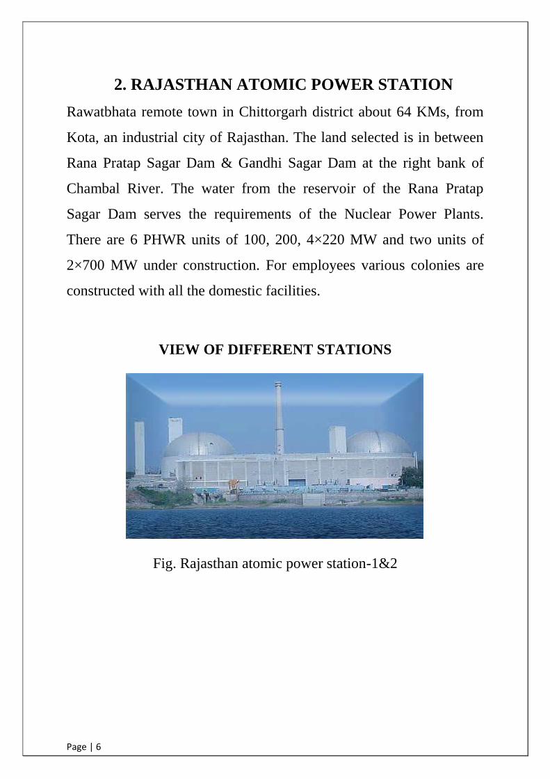
2. RAJASTHAN ATOMIC POWER STATION
Rawatbhata remote town in Chittorgarh district about 64 KMs, from
Kota, an industrial city of Rajasthan. The land selected is in between
Rana Pratap Sagar Dam & Gandhi Sagar Dam at the right bank of
Chambal River. The water from the reservoir of the Rana Pratap
Sagar Dam serves the requirements of the Nuclear Power Plants.
There are 6 PHWR units of 100, 200, 4×220 MW and two units of
2×700 MW under construction. For employees various colonies are
constructed with all the domestic facilities.
VIEW OF DIFFERENT STATIONS
Fig. Rajasthan atomic power station-1&2

Page | 7
Fig. Rajasthan atomic power station-3&4
Fig. Rajasthan atomic power station-5&6
Fig. Rajasthan atomic power station-7&8

Page | 8
3. INDRODUCTION: NUCLEAR POWER PLANT
Considering the current population growth which has already crossed
100 crores in the 21st century and improvements in Standard of living
of the forthcoming generations, there will be a large increase in the
electrical energy particularly from Clean green and safe energy
sources. The electricity will play a vital role in sustainable
development of the country.
Among all the available conventional and non-conventional energy
sources, the nuclear energy in the most efficient abundantly available,
sustainable and cost effective energy sources. It does not emit
obnoxious gases that cause global warming, ozone hole and acid rain.
The energy needs of a country cannot be met from single sources.
Hydroelectric stations produces cheap power but need a thermal
backing to increase the firm capacity the coal reserves of the world
are fast depleting, the nuclear power is the only source, which can
supply the future energy demands of the world. They have an
installed power generation capacity of about 5780MW the shore of
the nuclear energy is only 2.1% of total energy generated in India.
The main advantages which nuclear power plant possesses are:
The amount of fuel used is small therefore the fuel cost is
low.
Since the amount of fuel needed is small, so there are no
problems of fuel transportation and storage.
Nuclear plants need less area then the conventional plants.
Page | 9
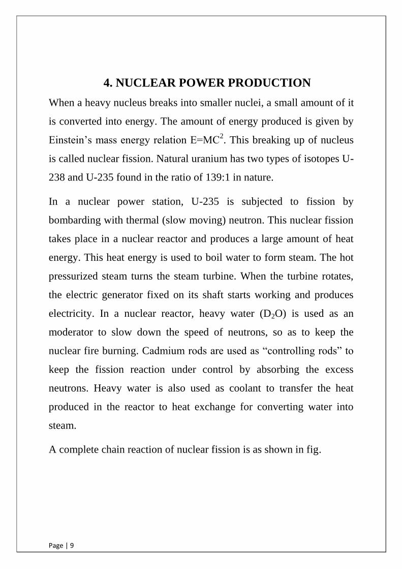
4. NUCLEAR POWER PRODUCTION
When a heavy nucleus breaks into smaller nuclei, a small amount of it
is converted into energy. The amount of energy produced is given by
Einstein‟s mass energy relation E=MC2. This breaking up of nucleus
is called nuclear fission. Natural uranium has two types of isotopes U-
238 and U-235 found in the ratio of 139:1 in nature.
In a nuclear power station, U-235 is subjected to fission by
bombarding with thermal (slow moving) neutron. This nuclear fission
takes place in a nuclear reactor and produces a large amount of heat
energy. This heat energy is used to boil water to form steam. The hot
pressurized steam turns the steam turbine. When the turbine rotates,
the electric generator fixed on its shaft starts working and produces
electricity. In a nuclear reactor, heavy water (D2O) is used as an
moderator to slow down the speed of neutrons, so as to keep the
nuclear fire burning. Cadmium rods are used as “controlling rods” to
keep the fission reaction under control by absorbing the excess
neutrons. Heavy water is also used as coolant to transfer the heat
produced in the reactor to heat exchange for converting water into
steam.
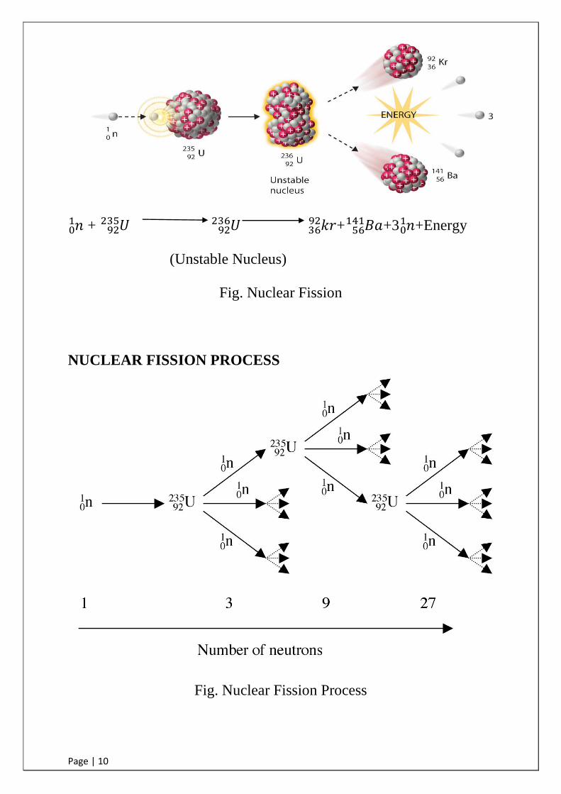
A complete chain reaction of nuclear fission is as shown in fig.
Page | 10
+
+ +3
+Energy
(Unstable Nucleus)
Fig. Nuclear Fission
NUCLEAR FISSION PROCESS
Fig. Nuclear Fission Process

Page | 11
5. NUCLEAR POWER PROGRAM &TECNOLOGY
IN INDIA
INTRODUCTION
India figured in the nuclear power map of the world in 1969, when
two boiling water reactors (BWRs) were commissioned at Tarapur
(TAPS 1&2) these reactors were built on the turnkey basis. The main
objective of setting these units was largely to prove the techno-
economic viability of nuclear power.
The nuclear power programme formulated embarked on the three-
stage nuclear power programs, linking the fuel cycle of pressurized
heavy water reactor (PHWR) & fast breeder reactors (FBR) for
judicious utilization of our reserves of uranium & thorium. The
emphasis of the programme is self-Reliance & thorium utilization as a
long- term objective.
THE THREE STAGES OF OUR NUCLEAR POWER
PROGRAMME ARE:
STAGE 1 = This stage envisages construction of natural uranium, heavy
water moderator & cooled pressurized heavy water reactors
(PHWR). Spent fuel from these reactors is reprocessed to
obtain plutonium.
STAGE 2 = This stage envisages on the construction of fast breeder
reactors (FBR) fuelled by plutonium & depleted U produced
in stage1. These reactors would also breed U233
from
thorium.
STAGE 3 = This stage would comprise power reactor using U233
–
thorium as fuel, which is used as a blanket in these type of
reactors.
Page | 12
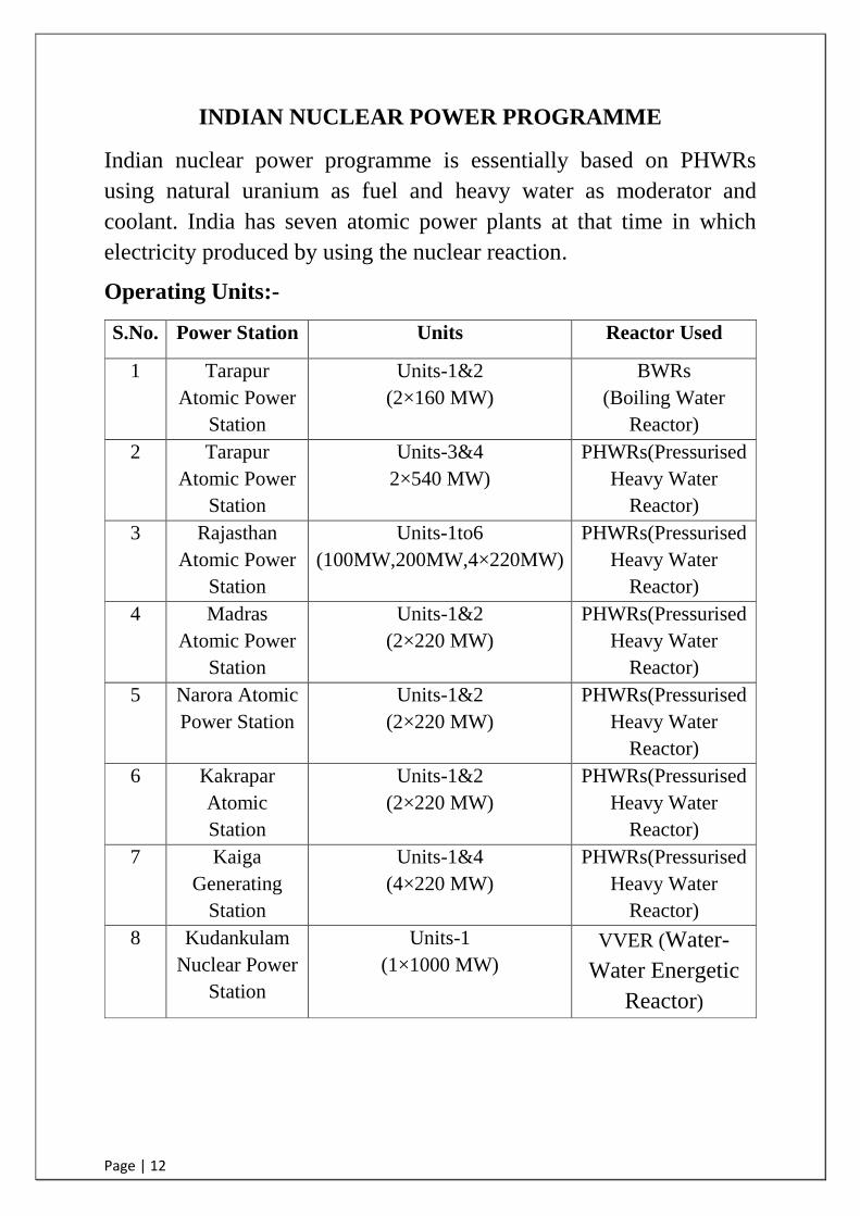
INDIAN NUCLEAR POWER PROGRAMME
Indian nuclear power programme is essentially based on PHWRs
using natural uranium as fuel and heavy water as moderator and
coolant. India has seven atomic power plants at that time in which
electricity produced by using the nuclear reaction.
Operating Units:-
S.No. Power Station Units Reactor Used
1 Tarapur
Atomic Power
Station
Units-1&2
(2×160 MW)
BWRs
(Boiling Water
Reactor)
2 Tarapur
Atomic Power
Station
Units-3&4
2×540 MW)
PHWRs(Pressurised
Heavy Water
Reactor)
3 Rajasthan
Atomic Power
Station
Units-1to6
(100MW,200MW,4×220MW)
PHWRs(Pressurised
Heavy Water
Reactor)
4 Madras
Atomic Power
Station
Units-1&2
(2×220 MW)
PHWRs(Pressurised
Heavy Water
Reactor)
5 Narora Atomic
Power Station
Units-1&2
(2×220 MW)
PHWRs(Pressurised
Heavy Water
Reactor)
6 Kakrapar
Atomic
Station
Units-1&2
(2×220 MW)
PHWRs(Pressurised
Heavy Water
Reactor)
7 Kaiga
Generating
Station
Units-1&4
(4×220 MW)
PHWRs(Pressurised
Heavy Water
Reactor)
8 Kudankulam
Nuclear Power
Station
Units-1
(1×1000 MW)
VVER (Water-
Water Energetic
Reactor)

Page | 13
Units Under Construction:-
1 Kudankulam Nuclear
Power Station
Unit-2
(1×1000 MW)
VVER(Water-
Water Energetic
Reactor)
2 Kakrapar Atomic
Station
Units-3&4
(2×700 MW)
PHWRs
(Pressurised Heavy
Water Reactor)
3 Rajasthan Atomic Power
Station
Units-7&8
(2×700 MW)
PHWRs(Pressurised
Heavy Water
Reactor)
6. MAIN PARTS OF NUCLEAR POWER PLANT
The main and auxiliary equipment of layout in nuclear power plant
are described below:-
a) Nuclear Reactor
b) Turbine
c) Steam generator
d) Calandria
e) Coolant assembly
f) End shield
g) Cooling Tower
h) Moderator pump & auxiliaries
i) PHT pumps
j) Fuel
k) Fuel design
l) Fuel handling
m) Moderator system
n) PHT system
o) Reactivity control mechanism
a) NUCLEAR REACTOR A reactor plays an important role in nuclear power plant. In NPP, heat
energy is produced by the fission of nuclear fuel such as uranium, in a

Page | 14
reactor thus, the source of heat energy is the reactor, which is
equipment to the furnace in a coal fired plant. It is necessary to
transport this energy to the turbine where it is changed into
mechanical energy of rotation.
Fig. Reactor Building Schematic
In concept, the Indian Pressurised Heavy Water Reactor is a pressure
tube type reactor using heavy water moderator, heavy water coolant
and natural uranium dioxide fuel. The reactor consists primarily of
Calandria, a horizontal cylindrical vessel. It is penetrated by a large
number of Zircaloy pressure tubes (306 for 235 MW reactor),
arranged in a square lattice. These pressure tubes, also referred as
coolant channels, contain the fuel and hot high-pressure heavy water
coolant. End-shields are the integral parts of the calandria and are
provided at each end of the calandria to attenuate the radiation
Page | 15
emerging from the reactor, permitting access to the fuelling machine
vaults when the reactor is shutdown. The calandria is housed in a
concrete vault, which is lined with zinc metallised carbon steel and
filled with chemically treated demineralised light water for shielding
purposes. The end shields are supported in opening in the vault wall,
and form a part of the vault enclosure at these opening. Each pressure
tube is isolated from the cold heavy water moderator present in
calandria by a concentric zircaloy calandria tube.
b) TURBINE
Turbine is tandem compound machine directly coupled to electrical
generator. A turbine generally consists of low-pressure cylinder
(double flow for 500 MW units).
Turbine has a maximum continuous & economic rating of 229 MW.
Turbine is the horizontal tandem compound re-heating impulse type
running at 3000RPM with special provision for the extraction of
moisture. A steam turbine converts heat energy of steam into
mechanical energy and drives the generator. It uses the principle that
the steam when issuing from a small opening attains a high velocity.
This velocity attained during expansion depends on the initial and
final heat content of steam. The difference between initial & final heat
content represents that the heat energy is converted into mechanical
energy.
c) STEAM GENERATORS
It converts water into steam for running of turbine. In steam
generator, water is converted into steam for running of turbine. Steam
generator is of U-Tube with mushroom shape orientation. Inside the
Page | 16
tube heavy water coolant of reactor flows for transfer of heat to light
water which flows outside of tube. At the top of steam generator, light
water is converted to steam. Four steam generators are situated in
each reactor building.
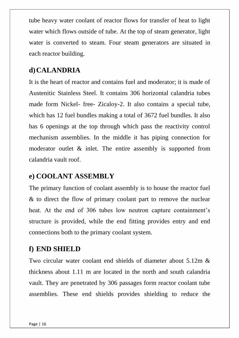
d) CALANDRIA
It is the heart of reactor and contains fuel and moderator; it is made of
Austenitic Stainless Steel. It contains 306 horizontal calandria tubes
made form Nickel- free- Zicaloy-2. It also contains a special tube,
which has 12 fuel bundles making a total of 3672 fuel bundles. It also
has 6 openings at the top through which pass the reactivity control
mechanism assemblies. In the middle it has piping connection for
moderator outlet & inlet. The entire assembly is supported from
calandria vault roof.
e) COOLANT ASSEMBLY
The primary function of coolant assembly is to house the reactor fuel
& to direct the flow of primary coolant part to remove the nuclear
heat. At the end of 306 tubes low neutron capture containment‟s
structure is provided, while the end fitting provides entry and end
connections both to the primary coolant system.
f) END SHIELD
Two circular water coolant end shields of diameter about 5.12m &
thickness about 1.11 m are located in the north and south calandria
vault. They are penetrated by 306 passages form reactor coolant tube
assemblies. These end shields provides shielding to reduce the

Page | 17
radiation in the fuelling machine vaults, the heat due to a closed water
circulation removes radiation from the calandria into shields.
g) COOLING TOWERS
Mainly there are two types of cooling towers:-
IDCT: Induct Draft Cooling Towers
NDCT: Natural Draft Cooling Towers
The main purpose of these cooling towers is to bring down the
temperature of circulating water. This is light water which circulates
through the heat exchanger and carry away the heat generated by the
DM water. This DM water condenses the steam. Hence by the
application of cooling towers the efficiency of the plant gets
enhanced.
Following is the description of these types of cooling towers:-
IDCT: As the name indicates it requires induced draft for cooling the
active process water. Big fans are used to produce the draft. The
active water is used in reactor building to cool various equipments.
NDCT: The inductive water, which is used to condense water, is
further cooled by natural draft. They are 150m high with hyperbolic
shape atomizing action.
h) MODERATOR PUMP AND AUXILIARY:
The main moderator circulating system consists of five pumps, two
heat exchangers, and necessary valves and piping. The pumps
circulate moderator from calandria through the two shells & tube heat
exchanger to keep the temperature between 60°C. The cooled heavy

Page | 18
water is again fed to the calandria. The moderator receives about 37
MWe fission heat. The system contains about 140,000 kg heavy
water.
i) PHT PUMPS
The PHT pump circulates the coolant (HW) in reactor core to steam
generator to generate steam. The complete system contains 8-
circulating pumps, 8-sets of boiler isolating valve of special design, 2
pressurizing pump, a stand by cooling system, a relief control valve
and feed & bleed system.
j) FUEL
The use of natural uranium dioxide fuel with its low content of fissile
material (0.72% U-235) precludes the Possibility of a reactivity
accident during fuel handling or storage. Also, in the core there would
no significant increase in the reactivity, in the ever of any mishaps
causing redistribution of the fuel by lattice distortion.
The thermal characteristics namely the low thermal conductivity and
high specific heat of UO2, permit almost all the heat generated in a
fast power transient to be initially absorbed in the fuel. Furthermore,
high melting point of UO2 permits several full power seconds of heat
to be safely absorbed that contained at normal power.
Most of the fission products remain bound in the UO2 matrix and
may get released slowly only at temperatures considerably higher than
the normal operating temperatures. Also on the account of the
Page | 19
uranium dioxide being chemically inert to the water coolant medium,
the defected fuel releases limited amount of radioactivity to the
primary coolant system.
The use of 12 short length fuel bundles per channels in a PHWR,
rather than full- length elements covering the whole length of the
core, subdivides the escapable radioactive facility in PHWR has also
the singular advantage of allowing the defected fuel to be replaced by
fresh fuel at any time.
The thin zircaloy-2/4 cladding used in fuel elements is designed to
collapse under coolant pressure on to the pellets. This feature permits
high pellet- clad gap conductance resulting in lower fuel temperature
and consequently lower fission gas release from the UO2 matrix into
pellet- clad gap.
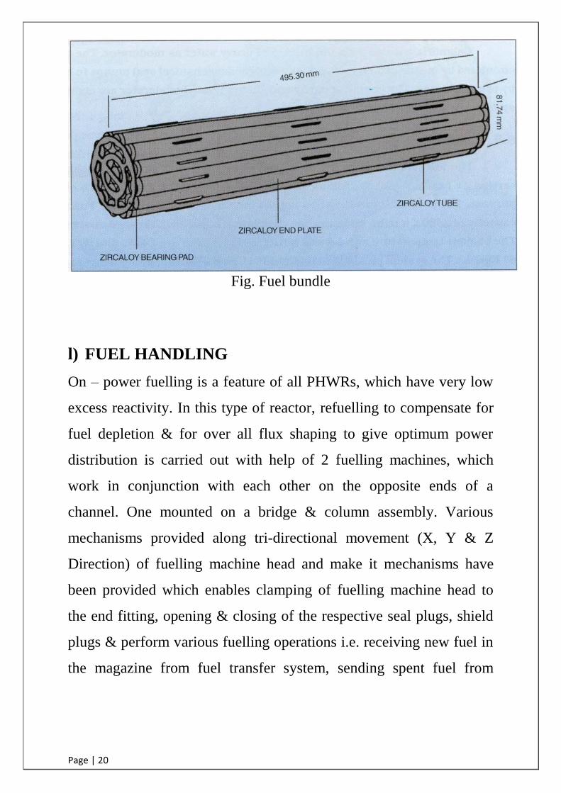
k) FUEL DESIGN
Fuel assemblies in the reactor are short length (half meter long) fuel
bundles. Twelve of such bundles are located in each fuel channel. The
basic fuel material is in the form of natural uranium dioxide a pellet,
sheathed & sealed in thin Zircaloy tubes. Welding them to end plates
to form fuel bundles assembles these tubes. A 19-element fuel bundle
is used in 220 MWe PHWRs. A fuel bundle is shown below.
Page | 20
Fig. Fuel bundle
l) FUEL HANDLING
On – power fuelling is a feature of all PHWRs, which have very low
excess reactivity. In this type of reactor, refuelling to compensate for
fuel depletion & for over all flux shaping to give optimum power
distribution is carried out with help of 2 fuelling machines, which
work in conjunction with each other on the opposite ends of a
channel. One mounted on a bridge & column assembly. Various
mechanisms provided along tri-directional movement (X, Y & Z
Direction) of fuelling machine head and make it mechanisms have
been provided which enables clamping of fuelling machine head to
the end fitting, opening & closing of the respective seal plugs, shield
plugs & perform various fuelling operations i.e. receiving new fuel in
the magazine from fuel transfer system, sending spent fuel from
Page | 21
magazine to shuttle transfer station, from shuttle transfer station to
inspection bay & from inspection bay to Spent fuel storage bay.
m) MODERATOR SYSTEM
The heavy water moderator is circulated through the calandria by aid
of a low temperature & low- pressure moderator system. This system
circulates the moderator through two heat exchangers, which remove
heat dissipated by high- energy neutrons during the process of
moderation. The cooled moderator is returned to the calandria via
moderator inlet nozzles. The high chemical purity and low
radioactivity level of the moderators are maintained through
moderator purification system. The purification systems consists of
stainless steel ion – exchange hoppers, eight numbers in 220MW
contains nuclear grade, mixed ion- exchange Resin (80% anion &
20% cation resins). The purification is also utilized for removable of
chemical shim; boron to affect start- up of reactor. Helium is used as a
cover- gas over the heavy water in calandria. The concentration
deuterium in this cover–gas is controlled by circulating it using a
sealed blower and passing through the recombination containing
catalyst alumina-coated with 0.3% palladium.
The purpose of heavy water moderator is to maintain criticality in the
reactor core by slowing down the high energy fast neutrons to low
energy thermal neutrons where their probability of fission capture is
greater.
Heavy water, used as moderator inside the calandria, gets heated up
due to neutron moderation and capture attenuation of gamma
Page | 22
radiation as well as due to the transfer of heat from reactor
components in contact. The heat in the moderator is transported to the
moderator heat exchangers outside the core where it is removed by
process water. Circulation of moderator through moderator heat
exchangers is accomplished by moderator pumps.
In Units 5&6 moderator is filled up to 100% as the shutdown
mechanism is entirely different. It has got primary shut off rods which
gets inserted into calandria and absorbs neutrons, thus causing a
breakage of chain reaction.
For this there are 14 shut off rods made up of cadmium sandwiched in
SS. The other components of the moderator system consists of
calandria, coolant channels, over pressure rupture disc, expansion
joints, moderator pumps, heat exchangers and control valves.
n) PRIMARY HEAT TRANSPORT (PHT) SYSTEM
The system, which circulates pressurized coolant through the fuel
channels to remove the heat generated in fuel, referred as Primary
Heat Transport System. The major components of this system are the
reactor fuel channels, feeders, two inlet headers, two reactor outlet
headers, four pumps & interconnecting pipe & valves. The headers
steam generators & pumps are located above the reactor and are
arranged in two symmetrical banks at either end of the reactor. The
headers are connected to fuel channels through individual feeder
pipes. The coolant circulation is mentioned at all times during reactor
operation, shutdown & maintenance.

Page | 23
o) REACTIVITY CONTROL MECHANISMS
Due to the use of natural uranium fuel & on-load refuelling, the
PHWR‟s do not need a large excess reactivity. Standard reactor
designs are provided with four systems for reactivity control, viz.
1. Regulating rods.
2. Shim rods.
3. Adjuster rods for xenon override
4. Natural boron addition in the moderator to compensate for the
excess reactivity in a fresh core & for absence of xenon after a long
shutdown.
The reactivity control devices are installed in the low-pressure
moderator region & so they are not subjected to potentially severe
hydraulic & thermal forces in the event of postulated accidents.
Furthermore, the relatively spacious core lattice of PHWR allows
sufficient locations to obtain complete separation between control &
protective functions. The regulating systems are thus fully
independent with its own power supplies, instrumentations &
triplicate controls channels. Cobalt & stainless steel absorber elements
have been utilized in the reactivity control mechanisms. For 220MW
standardized design, two diverse, fast acting & provides a high degree
of assurance that plant transients requiring prompt shutdown of the
reactor will be terminated safety. The primary shutdown system
consists of 14 mechanical shut off rods of cadmium sandwiched in
stainless steel & makes the reactor sub critical in less than 2 sec. Fail-
safe features like gravity fall & spring assistance has been
incorporated in design if mechanical shut off rods. The second
shutdown system, which is also fast acting, Comprise 12 liquid poison
tubes, which are filled with lithium pent borate solution under helium
pressure. The trip signal actuates a combination of fast acting valves
and causes poison to be injected simultaneously in 12 interstitial
liquid poison tubes of calandria of the machines is used to fuel the
channel while the other one accepts the fuel bundles. In, Addition,
the fuelling machines facilitate removal of failed fuel bundles. Each
fuelling machine is mount thin zircaloy tubes. Welding them to end
plates to form fuel bundles assembles these tubes.
Page | 24
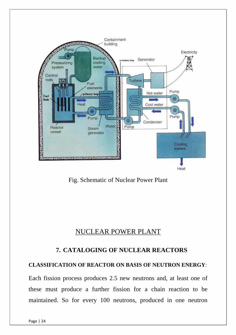
Fig. Schematic of Nuclear Power Plant
NUCLEAR POWER PLANT
7. CATALOGING OF NUCLEAR REACTORS
CLASSIFICATION OF REACTOR ON BASIS OF NEUTRON ENERGY:
Each fission process produces 2.5 new neutrons and, at least one of
these must produce a further fission for a chain reaction to be
maintained. So for every 100 neutrons, produced in one neutron
Page | 25
generation, at least 40 must cause further fissions so as to produce 40
x 2.5 or 100 neutrons in the next generation. Now the neutrons
produced at fission are fast neutrons with an average energy of 2
MeV. If the fissions occur in natural uranium fuel, 99.3% of the
nuclei are U-238 is solitary responsible for the fission with neutrons
having energies greater than 1.2 MeV, therefore only half the fission
neutrons can cause U-238 fissions. So out of the 100 neutrons
produced at fission, only 50 can cause U-238 fissions.
The inelastic scattering cross-section of U-238 is 10 times greater
than the fission cross-section at these neutron energies. So, out of
these 50 neutrons 5 will be able to cause fission and remaining 45 will
be scattered and lose so much energy that they can no longer cause U-
238 fission. The fast fission cross section in U-235 is only 1.44 barns
and U-235 fast fissions can be ignored with so little U-235 in natural
uranium. Therefore, out of the 100 fast neutrons produced at fission
only 5 will cause further fissions and produce 5 x 2.5 new neutrons.
Thus even if leakage and radioactive capture are ignored the chain
reaction cannot be maintained by fast neutrons in natural uranium.
a) BOILING WATER REACTOR
BWR uses enriched uranium oxide as fuel and has a steel pressure
vessel surrounded by concrete shield. It is a direct cycle reactor. The
steam is generated in reactor itself and this steam, after passing
through turbine and condenser, returns to the reactor. In view of direct

Page | 26
cycle there is danger of contamination of steam. Ordinary water is
used both coolant and moderator.
The reactors of Tarapur Atomic Reactor Power station (India) are of
this type.
The advantages of this reactor include a small size pressure vessel,
high steam pressure and simple construction.
Fig. Boiling Water Reactor
b) PRESSURIZED HEAVY WATER REACTOR (PHWR)
PHWRs have established over the years a record for dependability,
with load factors in excess of 90% over extended periods. In the
PHWR, the heavy water moderator is contained in a large stainless
steel tank (calandria) through which runs several hundred horizontal
zircaloy calandria tubes. The D2O moderator is maintained at
atmospheric pressure and a temperature of about 70°C. Concentric
with the calandria tube, but separated by a carbon dioxide filled

Page | 27
annulus which minimizes heat transfer from fuel to the moderator, is
the zircaloy pressure tube containing the natural UO2 fuel assemblies
and the heavy water coolant at a pressure of about 80 kg/cm² and a
temperature of about 300°C. The term pressurized refers to the
pressurized D2O coolant which flows in opposite directions in
adjacent tubes and passes its heat to the secondary coolant via the
steam generators. System pressure is maintained by a pressurizing one
of the legs of a steam generator.
Fig. Pressurized Water Reactor
c) FAST BREEDER REACTORS
The U-235 content of the fuel can be increased, i.e., the fuel is highly
enriched in U-235 with a substantial decrease in U-238. The U-235
fast fissions are thus, considerably increased in a fast reactor. Some
reduction in neutron energy does occur due to inelastic collisions of
neutrons with nuclei of the fuel and structural material but most of the
fissions are caused by neutrons of energies greater than 0.1Mev.The
Page | 28
mass of U-235 required for the reactor to be critical varies with a
mount of U-235 enrichment. In all cases the critical mass of fissile
material required increases rapidly below 15% to 20% U-235
enrichment. To avoid large fuel inventories a fast reactor, would
require fuel containing at least 20% U-235 by volume. Incidentally
the critical mass of U-235 in a fast reactor is considerably greater than
in a thermal reactor with the same fuel composition.
The highly enriched fuel, absence of moderator results in a small core.
Therefore, fast reactors have high power density cores. The average
power density in a (FBR) is 500 MW/m3 compared with 100 MW/m3
for a (PWR). It is therefore essential that a heat transport fluid with
good thermal properties be used. The choice is also limited to a non-
moderating fluid & liquid metals seem to satisfy both requirements.
The capture cross-sections of most elements for fast neutrons are
small & since there is a relatively large mass of U-235 in the reactor,
the macroscopic capture cross-sections of structural material and
fission products are small compared with the macroscopic fission
cross-section of the U-235.Consequently there is more flexibility in
the choice of materials and stainless steel can be used instead of
aluminium or zirconium. Fission product poisoning is not significant
as that temperature coefficient of reactivity is low; the excess
reactivity required in a fast reactor is small.

Page | 29
Fig. Fast Breeder Reactor
8. CRITERIA FOR SELECTION OF SITES FOR
NUCLEAR POWER PLANT
OBJECTIVE
The main objective in siting of Nuclear Power Plants from the point of
view of nuclear safety is to be able to construct and operate Nuclear
Power Plants safely & to provide protection to the public against
radiological impact resulting from accidental releases of radioactive
material as well as release of such materials during normal operation of
the plant. Hence the basic criteria for selection of a site for the location
of a nuclear power plant shall be to ensure that the site plant interaction
will not introduce any radiological risk or others of an unacceptable
magnitude.
Page | 30
This can be achieved by:
A. The radiological risk to the Nuclear Power Plant due to the external
events should not exceed the range of radiological risk associated
with accidents of internal origin.
B. The possible radiological impact of a Nuclear Power Plant on the
environment should be acceptably low for normal operation, an
accident conditions and within the stipulated criteria for radiological
safety.
In evaluating the suitability of a site for locating a Nuclear Power Plant,
the following are the major aspects that need to be considered:
Effect of external events
(nature & man – induced) on the plant.
Effect of plant on environment
& population
Implementations of emergency
procedures particularly counter measures in the public domain.
DESIGN BASIS FOR INTERNAL NATURAL EVENTS
Natural phenomenon, which may exist or can occur in the region of a
proposed side, shall be identified and these should be classified as per
their importance. Design basis shall be derived for each important
event by adopting appropriate methodologies. These should be
justified as being compatible with the characteristics of the region &
also with the current state of art of the extent possible.

Page | 31
DESIGN BASIS FOR EXTERNAL MAN - INDUCED EVENTS
Proposed sites shall be adequately investigated with respect to all the
design basis man- induced events that could affect the plant safety.
The region shall be examined for facilities and human activates that
may affect the safety of the proposed Nuclear Power Plant. These
facilities & activates shall be identified and the conditions under
which the safety of the plant is likely to be affected shall be
considered in fixing the design basis for man-induced events.
Information concerning the frequency & severity of those important,
man-induced events shall be collected & analysed for reliability,
accuracy & completeness.
RADIOLOGICAL IMPACT ON THE ENVIRONMENT
The radiological consequences due to Nuclear Power Plant on
environment should be as low as is reasonably achievable taking into
account. Social and economical factors, both for normal & accidental
conditions are within the stipulated criteria for radiological safety.
In evaluating a site for the radiological impact by the Nuclear Power
Plant on the region for operational states & accidental conditions,
appropriate estimates shall be made of expected or potential releases
of radioactive material taking into account the design of the plant
including its safety features.

Page | 32
The direct & indirect pathways, by which radioactive materials
released from the Nuclear Power Plant could reach & affect the
people, shall be identified for use in the estimation of the radiological
impact. Thus, the main points to be considered for sitting Nuclear
Power Plants are as follows:
A. Land requirements.
B. Accessibility.
C. Construction facility.
D. Cooling water.
E. Electrical system and energy resources.
F. Geology.
G. Seismology.
H. Flooding.
I. Natural events.
J. Man-induced events.
K. Population.
L. Radiological impact.
M. Meteorological & air releases.
N. Hydrology & liquid waste.
O. Geo hydrology & solid waste.
SAFETY DESIGN PRINCIPALS
It has been ensured that systems, components & structures having a
bearing on reactor safety are designed to meet stringent performance
& reliability requirements. These requirements are met by adopting
the following design principles:
a) The quality requirements for design, fabrication,
construction, & inspection for these systems are of the
high order, commensurate with their importance to safety.
Page | 33
b) The safety related equipment inside the containment
building is designed to perform its function even under the
elevated pressure & temperature & steam environment
conditions expected in the event of postulated loss of
coolant accidents (LOCA).
c) Physical & functional separation is assured between
process systems & safety systems.
d) Adequate redundancy is provided in systems such that the
minimum safety functions can be performed even in the
event of single active components in the system.
e) To minimize the probability of unsafe failures.
f) Provisions are incorporated to ensure that active
components in the safety systems are testable periodically.
g) All the supplies/services (electric, compressed air or
water) to these systems, necessary for the performance of
their safety functions are assured & „safety grade‟ sources.
Page | 34
9. WASTE MANAGEMENT FACILITY
A waste management site for the storage / disposal of low
intermediate level solid / solidified waste generated in the exclusion
zone of 1.6 km radius of the reactor which is exclusively under the
control of the power plant. This is a small area of the exclusion zone
and it is isolated from the public use after retiring of the station until
the radioactivity decays down to acceptable levels. Radioactive
wastes can be categorized in three types, they are:-
1. SOLID WASTE
This type of waste is disposed deep inside the earth (1000-1500m).
The least radioactive waste i.e. 0-2 mSv/year is disposed into earth
trenches. The radioactive waste from 2 mSv – 50 mSv/year is
disposed in RCC trenches and the rest from 50 mSv/year radioactive
waste is disposed in the tie holes.
2. LIQUID WASTE
This type of waste is treated separately in a different plant where after
applying ion exchange method we release this water into the lake.
3. GASEOUS WASTE
Gaseous radio nuclides are generated during the operation of NPPs
fission in fuel and activation product in vault air cooling. These
gaseous nuclides are passed through filters and absorbers before
releasing them to atmosphere.

Page | 35
10. SAFETY
INDUSTRIAL SAFETY
We mean that the measures adopted as a whole in industry to reduce
accidents to bare minimum.
Factors responsible for Safety:
Plant layout
Design of machinery
Safety Gadgets and equipments
Protective aids
Safety culture & Respect for Safety
Attitude of the management/ employer - Caution Boards
Display of Good practices about Safety
Safety meetings, Open discussion and other measures
Safety Manual
Enforcement
Unsafe Act & Unsafe conditions
Causes of Accidents
Hazards are the risks and perils or dangers that contribute to accidents
and injuries.
"HAZARDS DO NOT CAUSE ACCIDENTS, PEOPLE DO"
Kinds of Hazards:
Fire
Heat

Page | 36
Material Handling
Floors
Ladders
Tools
Machinery
Walking and Working surfaces
Process
Chemicals
Electricity
Unsafe Act
Unsafe Condition
RADIATION SAFETY
Radiation in Nuclear reactor is produced in following ways:
Directly in fission reaction
By decay of fission products
Following types of radiations are encountered:
Alpha radiation
Beta radiation
Gamma radiation
Neutron radiation
Out of the above types of radiations Alpha radiation is practically
zero, whereas Beta and Gamma radiation fields may be present almost
everywhere inside the reactor building and in negligible amount even
outside the reactor building. Neutron radiations are mainly present
inside the reactor vault. It is worth noting that the secondary side of
Page | 37
the plant i.e. feed water and steam cycle etc. are completely separate
from the nuclear systems and are therefore not supposed to be and
neither they are to carry any sort of radioactive particle and therefore
free of contamination and radiation. It is also worth noting that all
radiations are emitted from the nucleus of every radioactive nuclide
which will always have a tendency to become stable by emitting
radiations through disintegration. Following methodologies are used
to control the exposure to the radiation and therefore resistive of the
radiation dose.
(1) Administrative Control
(2) Zoning Technique
(3) Design Control
(4) Operation Control
(5) Maintenance and House keeping
Exposure to any kind of radiation can be controlled by an individual
by following methods:
(1) Distance
(2) Shielding
(3) Decay (Time to Decay)

Page | 38
11. FIRE SECTION
RAPS have one common fire section from unit 1-6. It is located at
3&4 unit area. For fire production mainly three things are required:
1) Fuel for burning
2) Oxygen to support fire and
3) The third one is temperature.
For fire extinguishing we remove any one out of these three things.
CLASSIFICATION OF FIRE
S.NO. CLASS
OF
FIRE
SOURCE OF FIRE BEST EXTINGUISER
1. A wood, paper, ordinary
combustibles
Soda, acid, water
2. B Oil, paints, grease, gasoline, diesel,
petrol
Foam, CO2
3. C Fire in gaseous substances(H2) CO2 gas
4. D Fire in chemicals, metals CO2, dry chemical
5. E Electrical fire CO2, dry chemical
Page | 39
12. ENVIRONMENTAL SURVEY LABORATORY
OBJECTIVES OF E.S.L. LAB AT RAWATBHATA
Measurements of concentration of radio nuclides in various
environmental matrices collected from the environment of
Rawatbhata Nuclear Site.
ATMOSPHERIC TERRESTRIAL AQUATIC
Air Tritium Soil Water
Rain water Grass Silt
Sulphide Cereals Sediment
Air Particulate Pulses, Milk, Meat Fish, Weed
Measurement of internal contamination due to gamma emitting
radionuclides by whole body counting of RAPS radiation workers.
• Measurement of direct radiation exposure using environmental
thermo luminescent dosimeters.
• Computation of radiation does to the public and demonstrates
compliance with applicable regulatory limits.
• Monitoring of drinking water quality and sewage effluent
samples for Public health criteria.

Page | 40
13. CONCLUSION
The practical training at R.A.P.S. has proved to be quite faithful. It
proved an opportunity for encounter with such huge components like
220MW generators, turbines, transformers and switchyards etc. The
way various units are linked and the way working of whole plant is
controlled make the students realize that engineering is not just
learning the structure description and working of various machines,
but the greater part is of planning, proper management.
It also provides an opportunity to learn technology used at proper
place and time can save a lot of labour for example almost all the
controls are computerized because in running condition no any person
can enter in the reactor building.
But there are few factors that require special mention. Training is not
carried out into its tree spirit. It is recommended that there should be
some practical work specially meant for students where the presence
of authorities should be ensured. There should be strict monitoring of
the performance of students and system of grading be improved on
the basis of the work done. However training has proved to be quite
faithful. It has allowed as an opportunity to get an exposure of the
practical implementation to theoretical fundamental.