Embed Size (px)
Citation preview

Network EssentialsC H A P T E R 4

A network is a collection of systems and devices exchanging data over some form of media.
A host is defined as any device that holds a logical address on your network.
Hosts can be workstations, servers, printers, connection devices, or routers.

Modern networks are charged with delivering our phone calls and, soon, our television and
entertainment options. Data—no matter what its form—is transmitted in the form of bits.
A single bit is a 1 or a 0 (based on the binary number system of two digits versus the typically
used decimal numbering system based on the digits 0–9).

A protocol is simply an agreed upon set of rules for a particular network function.
Bandwidth is generally considered to be the total amount of data (in bits) you can theoretically
transmit within a given time period (typically one second).
Bandwidth is expressed in bits or bytes per second in digital networking.

Network Topologies The topology can refer to how the network actually looks
Physical Topologies:
The physical topology of the network refers to how the network actually looks from a
bird’s-eye view—the physical cabling layout of the network itself.

A bus topology consists of all devices connecting to a single wire—a coaxial cable.
A physical bus looks like a straight line—a stick—with connections to hosts coming off
in a “T” shape.
In a ring topology, all devices are connected to each other in the shape of a circle—the first
device feeds into the second device, which in turn feeds into the third, and so on and so on until
the loop plugs back into the first device

Star topologies can also include extended star, where the central device extends links to other
hubs and switches.
A token passing, or ring, topology works in a more organized, almost friendly format. In a
token passing logical topology, systems can only transmit information when they hold a special
data packet, known as a token. The token is passed from one device to the next, in a prescribed,
circular path. Each device receives the token and examines it. If it holds a message for the
device, it will open and process it.

Network Categories Networks are typically of two types: LANs and WANs.
LANs :
A LAN (local area network) can be defined as a network that serves users within a small geographic footprint.
WANs:
A WAN(wide area network ) is nothing more than the network connecting a collection of LANs across a wide geographic area—perhaps a state, nation, or even the whole world! Aside from the distance variable, another defining characteristic of WANs is the concept of a leased line.

The OSI Reference Model 11 CERTIFICATION OBJECTIVE 1.02 The OSI Reference Model
One word bandied about quite a bit in regards to the OSI model is encapsulation.
Encapsulation is the process of adding a header and a trailer to a piece of data. While each stage
of communication (layer of the model) adds a header to the data, only one layer always adds a
trailer. Some texts define encapsulation as occurring in all layers of the model; however, it
technically only occurs at one—the Data Link layer.
The Layers The OSI Reference Model splits the communications process into seven distinct modular layers,
with each layer accomplishing a specific function independently of all other layers. The layers do
rely on layers above and below to provide something to work with, but they don’t necessarily
care what they receive to work with.

The OSI REFERENCE MODEL SERIESAPPLICATION LAYER(7)
PRESENTATION LAYER(6)
SESSION LAYER(5)
TRANSPORT LAYER(4)
NETWORK LAYER(3)
DATALINK LAYER(2)
PHYSICAL LAYER(1)

LAYER DEVICES FOUND IN THE LAYER PROTOCOLS AND STANDARDS WORKING
Application Firewall,Gateway and IDS SMTP,POP3,DNS,DHCP,FTP,HTTP,TFTP,SNMP
Presentation N/A JPG,JPEG,TIFF,GIF,MIME
Session N/A NFS,ASP,SQL,RPC
Transport Firewall TCP,UDP, SPX
Network Router IP,IPX, Appletalk
Data link layer Bridge and Switch Ethernet,ATM,PPP,Frame Relay
Physical Transceiver,Repeater, and Hub RJ45,ST/SC

The Data Layers (Application,Presentation, and Session)
Seven layers of the OSI model:-
The data layers would be the top three layers of the model.
At the top of the stack, we find layer 7—the Application layer
The Application layer holds the protocols that allow programs to access and make use of a
Network.

For example, Microsoft Outlook—a common e-mail program—can work just fine without a
network. You can open, edit, create, and delete e-mails offline just as well as you can online.
However, if you wish to use the network to send and receive e-mail, you need an Application
layer protocol to do this. In this example, the Application layer protocol would be SMTP.

Continuing the e-mail analogy, imagine you are sending an e-mail from a Microsoft Outlook
application to a computer running the Thunderbird e-mail application. You may have bold,
italics, and any number of font settings within your e-mail. Additionally, you may attach a picture
file (jpg) for the recipient to enjoy. Thunderbird might treat bold, italics, and font settings
differently than does Outlook, and SMTP is only capable of sending ASCIIcode (a combination of
bits representing an alphanumeric character, commonly referred to as, simply, text).

Enter layer 6—the Presentation layer. The Presentation layer is responsible for formatting and
code conversion between systems. This layer accepts the data from the Application layer and
ensures it is placed in a format the end station can understand. In this case, the e-mail is in text
mode, and another protocol, like MIME, translates the jpg into ASCII for transit. Once received at
the far end, the recipient’s Presentation layer will perform the reverse, handing the data back to
the Application layer protocol. Encryption is another function of the Presentation layer

Layer 5—the Session layer:—is perhaps the most enigmatic and troublesome of the entire
stack. This layer doesn’t necessarily do anything to the data at all. Instead, its function is to
work in the background, ensuring the communications process between two systems runs
smoothly.
The Delivery Layers:-

Transport layer:
Transport the data from receiver to sender.
The three main functions:
1. Segmentation.
2. The reliable delivery
3. Flow control

Segmentation is simply taking a small piece of the bits making up the data as a whole.
A small header is put in front of these bits. Inside the header is all sorts of information,
including:
The Network layer is responsible for logical addressing and routing.
Receiving a segment from the Transport layer, the Network layer adds a header that includes a
source and destination logical (network) address. This address is read by layer-3 devices
(routers) and best path determinations are made to deliver the segment to its final destination
Network Components Physical Layer Devices:
Physical layer devices do nothing more than physically connect wiring together to complete a path, or change the connection from one type to another.
Examples of physical layer devices include transceivers, repeaters, and hubs.
Transceivers connect one media type to another, such as a fiber connection to a copper one.
Repeaters are used to extend the range of a given media—whatever they take in one port,
they regenerate and repeat out the other. Hubs are nothing more than multiport
repeaters. Comparatively, where a repeater takes bits in one port to relay to another,
hubs have several ports they accept and relay bits on.

Data Link Layer Devices Layer-2 devices include bridges and switches. Switches and bridges split (or
segment) collision domains, decrease network traffic problems, and increase effective
available bandwidth to hosts. However, keep in mind they are incapable of moving
traffic outside your LAN.

Network Layer Devices Network layer devices play a unique role in your network design. These devices read the
Logical network addresses on your data and make decisions about which route to
send the data. This sounds very much like the switches and bridges discussed earlier,
but keep in mind the layer-3 device not only knows which port to send the data out,
but also the best route through outside networks to its final destination. Continuing
the analogy from earlier, if the street address on your letter is akin to the physical
address of your hosts, the logical address used by layer-3 devices is equivalent to the
ZIP code.

Other Devices Networks can also include a variety of other devices, such as firewalls, gateways,
and proxies. A firewall is a device that typically works at layers 3 and 4, and is
used to filter network traffic based upon rules the administrator configures on
the device. Generally placed between your network and the Internet, firewalls
work on an implicit deny principle—if you do not explicitly allow the traffic, it is
blocked.

Gateways work at all layers and are generally used to connect networks and applications of
different types together. A proxy is a system that provides a specific service to a host. For
example, a web proxy will make requests to the Internet for web content on behalf of a host.
This increases security and performance since web traffic coming from your network appears
from only one system, and hosts can access cached pages on the proxy instead of going out to
find them. Generally speaking, these devices are usually placed between your network and the
Internet in a special network called a DMZ

TCP/IP TCP/IP eventually became accepted as the worldwide standard for communication due to its
open architecture and, eventually, public input on its inner working.
Comparing Models:
TCP/IP divides networking functions into distinct layers. However, TCP/IP does so with only four
layers: Application, Transport, Internet, and Network Access. All the functionality of the OSI
model also occurs within the TCP/IP model; however, the layers do not line up exactly.

OSI TO TCP/IP COMPARISIONOSI MODEL TCP/IP MODEL
APPLICATION LAYER APPLICATION
PRESENTATION LAYER APPLICATION
SESSION LAYER APPLICATION
TRANSPORT LAYER TRANSPORT
NETWORK LAYER INTERNET
DATA LINK LAYER NETWORK ACCESS
PHYSICAL LAYER NETWORK ACCESS

DNS The Domain Name Service (DNS) may well be the most widely and universally
used protocol within the Application layer. Its use is so ubiquitous within Internet
communications, it’s even used by other protocols! Therefore, it is absolutely
essential you understand the purpose of DNS and how it functions.

Caching is a process used to limit the number of queries that have to go all the way to the root.
Your computer has a DNS cache, and every name server and resolver along the way caches their
results. This means systems can sometimes get the answer to a query very quickly, especially if
others on their network have queried for the same record.

DHCP Another well-known and oft-used Application layer protocol is Dynamic Host Configuration
Protocol (DHCP). The main function of DHCP is to automatically assign IP addresses from a given
pool of addresses to clients within a specific network segment. The pool of addresses a DHCP
server uses is known as a scope. Servers and routers are generally configured as DHCP servers
within a network.

OTHER PROTOCOLS File Transfer Protocols
File Transfer Protocol (FTP) and Trivial File Transfer Protocol (TFTP) are both found in the TCP/IP
Application layer, and they both perform the same function—they transfer files from one system
to another. The manner in which they perform these functions differs, as well as where you
would traditionally see them in play. FTP is as much a service as it is a protocol, and is comprised
of a server, an authentication method, and the protocol itself. The FTP server is simply a
machine that has installed and enabled the FTP service.

TFTP has traditionally been used to transfer Cisco IOS and configuration files between Cisco
devices and a TFTP server on the network. Its small footprint, lack of extensive overhead, and
general ease of use make it an easy choice. FTP provides many more features, such as the ability
to list the fi les within the directory, and is a better choice for end users.

E-mail Protocols The protocols in play to move e-mail through networks are Simple Mail Transfer Protocol (SMTP)
and Post Office Protocol version 3 (POP3).
IMAP4 (Internet Message Access Protocol) is another protocol that may be used to pull an e-
mail message from a server. IMAP has a more sophisticated authentication structure than POP3,
but is not as commonly used in modern networks.

A URL is made up of three major components: the protocol used, the name of the server (or
host) holding the resource, and the name of the page. The protocol comes first, before the //.
The domain name listed, such as Cisco.com, comes next and is the host holding the resource.
Anything listed after the last “/” is the name of a specific resource (page) on the host.

Hyper Text Transport Protocol over SSL (HTTPS) uses much the same process,
but adds security and encryption to the process. Secure Sockets Layer (SSL) is an
encryption process that secures the communication between the client and the
server hosting the site. An exchange of certificates ensures the client can safely
exchange data without worrying about third-party interception. HTTPS is very
common in online banking, shopping, and secured data sharing implementations.
Both HTTP and HTTPS are connection-oriented protocols

Transport Layer Functions and Protocols
The TCP/IP Transport layer performs the same functions as its namesake layer in the OSI model:
segmentation, reliable end-to-end delivery of data, and flow control. Transport layer protocols
include Transport Control Protocol (TCP) and User Datagram Protocol (UDP).

TCP TCP is a connection-oriented reliable transport protocol used by applications that
require error correction in delivery. On the good side, TCP provides the reliability
services that applications may not have built into them.
Every TCP communication process begins with a session establishment process known as the three-
way handshake. In the first phase, the requesting system sends a synchronization request segment,
known as a SYN. The SYN segment is a simple request to open a communications channel, and
includes the SYN flag set, a sequence number, and port numbers (covered later in this chapter). When
the server receives this request, it formulates and sends a synchronization/acknowledgment
segment, known as a SYN/ACK. This segment includes the SYN and ACK flags set, an acknowledgment
of the requestor’s sequence number, and a separate sequence number. Finally, in the third step, the
requesting system sends an acknowledgment segment, known as an ACK. This segment includes the
ACK flag set, a copy of the acknowledgment of the original sequence number, and an
acknowledgment of the server’s own sequence number
Be sure to review and understand the three major functions accomplished within TCP. You will
definitely be asked questions testing your knowledge on the order transfer of data, requiring
you to predict sequence numbers from a given scenario. Pay close attention to the sequence
number itself, as well as the agreed-upon size.
UDP Unlike TCP, UDP is a connectionless protocol, meaning it does not require acknowledgments and
does not provide for error correction. A much simpler protocol with a smaller header, UDP
simply transmits segments as quickly as possible, without regard to the recipient. UDP has the
advantage of being much faster than TCP, but it does not provide many of the services that TCP’s
larger header allows for. If UDP is used as a transport protocol, reliability becomes a
function of the applications themselves.

UDP is a good choice in a couple of scenarios. If the data transfer is one (or just a
few) packets, then the overhead of TCP is unnecessary. Both DNS and DHCP are good
examples. In another good UDP scenario, the applications themselves must be capable
of tolerating lost packets, or have some means by which to ask for retransmissions. For
example, streaming video and Voice over IP (VoIP) can both tolerate a packet or two
lost along the way, as long as the stream doesn’t get too choppy.

Port Numbers and Multiplexing
Regardless of the transport protocol in use, there must be a method in place to let the recipient
Transport layer know which application protocol the transmitted segments should be passed to.
For example, imagine a server simultaneously hosting a web site and running an FTP service. A
TCP connection sequence occurs and a client connects to the server, sending a request for data.
How does the server know which application protocol—HTTP or FTP—is to handle the request?
Additionally, consider how confusing things could get if the same address asked for both services
in different streams. Port numbers are used to identify which protocol is to answer a
request and provide for multiplexing multiple requests from a single source
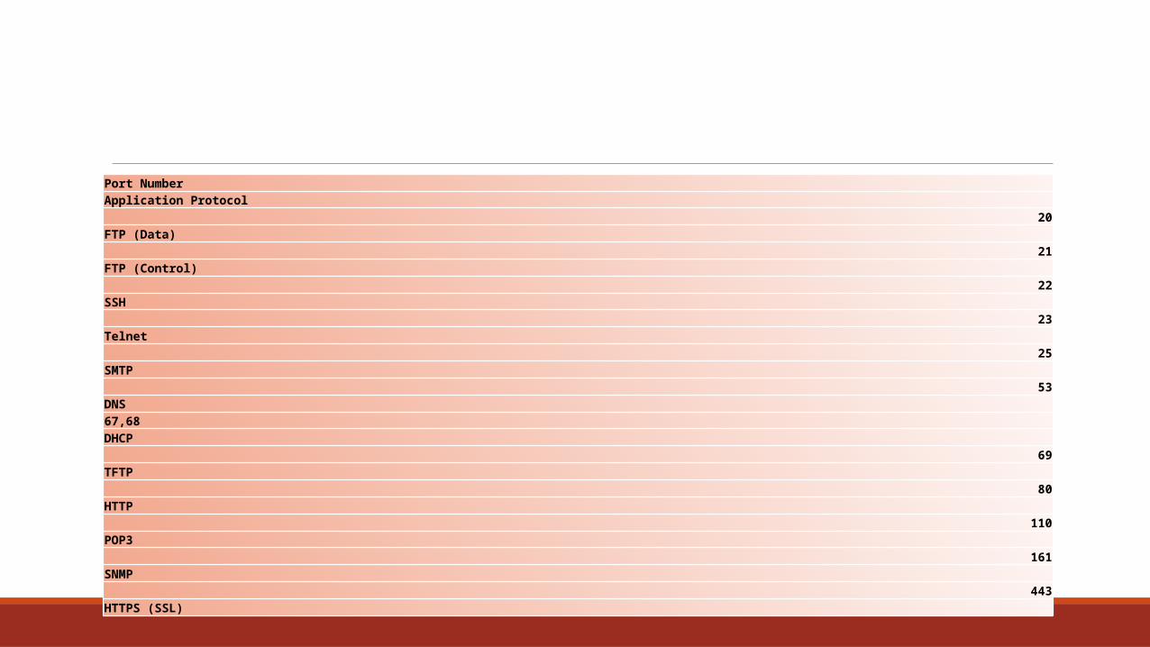
Port Number Application Protocol
20FTP (Data)
21FTP (Control)
22SSH
23Telnet
25SMTP
53DNS67,68DHCP
69TFTP
80HTTP
110POP3
161SNMP
443HTTPS (SSL)

Routed protocols can be routed across networks (or subnets). Routing protocols are used to
exchange information between routers to determine best path availability. You might also see a
reference to “non-routable” protocols on the exam. Non-routable protocols cannot,
obviously, be moved from one subnet to another. An example is NetBEUI.

IP AND ICMP
ping is a command-line tool used to test basic network connectivity. It sends an echo request to
a distant host, and if the host receives the message, it responds with an echo reply.
ping is usually used to systematically test network connectivity between two devices.
The IP address 127.0.0.1 (also known as localhost) is used to test the TCP/IP binding on the local
network card. Next, ping the default gateway for the system.

The responses to a ping display differently in a Cisco device, with a single character indicating
the message type. An exclamation point (!) indicates a good response. Other responses include a
dot (.) for timed out, and a capital “U” for destination unreachable. Also, be sure to
remember to ping from local to remote in troubleshooting scenarios

A final tool associated with ICMP is traceroute . The traceroute command displays all the IP
addresses of all routers along the path to the final destination, which obviously provides a much
more granular and meaningful snapshot in any troubleshooting scenario. The traceroute
command on Cisco devices displays the IP address of the next hop device along the path.

Network Access Layer Protocols
The Network Access layer of TCP/IP encompasses all the functionality of both the Data Link and
Physical layers of the OSI Reference Model. Encapsulation, framing, media access, and physical
addressing, as well as all the physical standards associated with cabling, connectors, and encoding, all
occur here. Each Network Access layer protocol defines a specific frame type in which to encapsulate
a packet for delivery within the network segment. In other words, the packet must be delivered
somewhere locally first, before it can make its way out of the network. If all devices on the media use
the same Network Access protocol and standard, the frame type is understood and the frame is
delivered to the appropriate device. The Network Access layer encompasses a wide variety of
protocols and standards, including SLIP, PPP, and Ethernet

Each network segment uses a specific Network Access layer standard. As the packet moves from
one network segment to the next, the frame is stripped off by the router and a new frame is
built for transmission on the next segment. For example, an Ethernet segment may pass
over a PPP or SLIP network on the way to its destination

Network Media Devices Copper Cabling:
Thicknet cabling (also known as 10BASE5) was the original Ethernet
transmission media. As its name implies, the cable itself is relatively thick, stiff,
and hard to work with. The benefit of thicknet is that its solid core is capable of
transmitting a signal up to 500 meters, and it is highly resistant to EMI. However,
connections to the bus required “vampire” clasps (taps), and data transmissions
were only capable up to 10 Mbps. Thicknet is no longer used as a data transmission
media, although it may appear in older networks

Twisted pair has replaced coaxial cabling as the media of choice for most new
network installations. Twisted pair cabling is relatively inexpensive and is simple
to work with and install. Signals do not travel as far on twisted pair as they do on
coax—generally, 100 meters on TP, with up to 500 meters on coax—however, they
do provide more options for network topologies and offer much greater transmission
speeds—up to 10 Gbps compared to coax’s 10 Mbps.

Just as with coax cabling, one of the most important pieces of the overall cable
plan is the connector allowing a device to access the wire. While thinnet cabling
used BNC connectors, T connectors, and Terminators, twisted pair makes use of
either an RJ11 or an RJ45 connector. RJ11 connectors—smaller, thinner, and using
only six pins (three pair)—are used on telephone twisted pair, while RJ45—larger,
thicker, and using eight pins (four pair)—is the choice for data networking.

Poor connectors are the number one source for almost all physical network
connectivity problems. On a twisted pair cable, be sure to check that the
Kevlar sheath has been pushed into the connector before crimping. If not, the
only things holding the connector to the wire are the small copper taps at
the end of the connector, and as a result, sooner or later, you’ll have problems
with that cable

The last cable type is more Cisco-specific and is not used to connect networking
devices together. A rollover cableis used in conjunction with a PC serial port and
a DB9-to-RJ45 transceiver to physically access a router or switch console port for
administrative purposes. Rollover cables map the pins to their opposite on the end
of the wire—pin 1 to pin 8, pin 2 to pin 7, and so on—rolling the signal over to the
opposite end. More on rollover cables and console administration will be covered later.
Many new Cisco devices have a built-in method to assist with cabling—the
port senses the pinout from the far end device and auto-configures the
port’s pinouts to match, no matter whether the cable is straight-through or
crossover. However, just because this feature is available, you shouldn’t throw
caution to the wind and simply use any cable lying around. Sticking with
convention assists in troubleshooting and reduces downtime later.

Fiber Cabling While copper cabling is much more common in data networks, fiber cabling offers
many advantages and is finding its way more and more into modern networks.
Fiber cabling encodes bits into light signals, which are totally immune from both

Fiber cables contain a glass or clear plastic core that is surrounded by a material
known as cladding. Cladding works like mirrors to reflect the light signal back
toward the core. As an analogy, consider a flashlight pointed at a wall. If you turn
the flashlight on and begin walking backward, the circle of light on the wall gets
larger, but dimmer. Light signals inside the wire tend to do the same thing, making
the signal weaken the further down the wire it travels. Cladding controls this
modal dispersion and ensures the signal stays clear and focused directly down the core of
the wire

Fiber cable is used as a backbone inside most LANs. Many times, the cable
(yellow or orange) will travel into a small transceiver, which allows a UTP or
STP cable to then run into your router or switch. Fiber can be used straight to
the desktop, but this is not very common
NICs Network interface cards (NICs) provide the interface your system needs to access to
physical media. Usually, NICs are built into the motherboard on the computer itself,
or are added as some form of expansion bus card. These cards can range from (older)
ISA boards and (newer) PCI boards to PCMCIA cards inserted into a laptop port.
The card installed on the system must match the media used. For example, you can’t
have a 10BASE2 coax card on a network using UTP—the ports and connectors
simply don’t match.

Transceivers , Repeaters , and Hubs
Transceivers do not read addresses, nor affect the data at all. They simply convert
the signal from one media type to another. Because they are “dumb” to addresses
and work purely on bits, transceivers are known as Physical (layer 1) devices.
Transceivers are most often seen when connecting a fiber ST or SC backbone to a
UTP or STP network, or at legacy router ports. Older Ethernet router ports were
built using an AUI connector, and a transceiver allowed a UTP cable to be used
with the AUI port.

Repeaters Bridges and switches do a great job of splitting collision domains and improving
LAN traffic speeds. However, switches and bridges do nothing to limit broadcasts
(bridges and switches flood all broadcast and multicast traffic), and cannot get traffic
Out of your network. For these functions, and more, you’ll need a router.

A router is used to connect networks. Acting much like a post office, the router
strips off the frame and looks at the Logical (layer 3) address. It then compares the
address to a route table and makes a determination on what to do with the packet. If
a route exists in the route table, the router will build the appropriate frame for that
network’s technology (Ethernet, Point-to-Point, Frame Relay, and so on) and send it
out the appropriate port. If there is no entry in the route table, the router will drop
the packet.

Route tables are built in one of two ways: static or dynamic. Static routing means
the administrator simply types in the routes for the route table. Dynamic routing
allows the routers within your network to share information with each other about
the networks they know of, and information regarding each link.

Security Devices While hubs, bridges, switches, and routers are used to move data around in the
network (and you can apply security actions to each), modern networks also make
use of devices specifically intended for security purposes