Embed Size (px)
Citation preview

Network Administration
0890432-050
August 2001

Copyright 2001 by Concurrent Computer Corporation. All rights reserved. This publication or any part thereof isintended for use with Concurrent products by Concurrent personnel, customers, and end–users. It may not bereproduced in any form without the written permission of the publisher.
The information contained in this document is believed to be correct at the time of publication. It is subject to changewithout notice. Concurrent Computer Corporation makes no warranties, expressed or implied, concerning theinformation contained in this document.
To report an error or comment on a specific portion of the manual, photocopy the page in question and mark thecorrection or comment on the copy. Mail the copy (and any additional comments) to Concurrent Computer Corpora-tion, 2101 W. Cypress Creek Road, Ft. Lauderdale, FL 33309–1892. Mark the envelope “Attention: PublicationsDepartment.” This publication may not be reproduced for any other reason in any form without written permissionof the publisher.
UNIX is a registered trademark, licensed exclusively by X/Open Company Ltd.
This document is based on copyrighted documentation from Novell, Inc. and is reproduced with permission.
Printed in U. S. A.
Revision History: Level: Effective With:
Original Release -- August 1994 000 Power UX Version 1.1
Previous Release -- March 1999 040 PowerMAX OS Version 4.3
Current Release -- August 2001 050 PowerMAX OS Version 5.1
Preface-1
Preface
About This Book
Network Administration is directed to system administrators who are setting up andmaintaining PowerMAX OS file sharing capabilities.
File sharing refers to the process of making file resources on your local system available toremote systems via a network, and conversely, to the process of accessing file resources onremote systems from your local system. The OS offers a file sharing package, also called a“distributed file system,” called the Network File System (NFS).
This guide tells you how to set up and administer NFS, and how to set up and administerDistributed File System (DFS), a software package that provides an interface to NFS. Alsoincluded in this guide is documentation that tells you how to set up and administer the OSimplementation of TCP/IP, Remote Procedure Call (RPC), and Network InformationSystem (NIS). Information about administering some mail service facilities associatedwith networking is also provided.
TCP/IP is a family of network protocols that determines how data is transferred across net-work media. TCP/IP supports NFS and is provided as the TCP/IP Internet package. It isnecessary that you install TCP/IP to run NFS, because NFS requires UDP/IP as itstransport. UDP/IP are protocols at the transport layer in the TCP/IP protocol family.
Included in TCP/IP at the application layer are a number of RPC commands and programsthat allow users to perform remote operations on another host on the network as if weretheir own host. In addition to providing support for NFS, the RPC mechanism alsosupports NIS. NIS is a facility for distributed network administration.
NOTE
This guide is not intended to be an introduction to networking, norto all the networking features of the OS.
How This Book is Organized
Because you may be setting up network services using a mix and match of applicationsand protocols, Network Administration is organized as seven parts that address the majortopics listed below.
• Part 1, “Network Services Administration”
This part provides an overview of networking, together with information aboutselecting a network, setting up name-to-address mapping, the connection server(which establishes connections for network services that communicate over TLIconnection-oriented and dialup connections), using authentication schemes (for
Network Administration
Preface-2
additional system security), setting up and administering ID mappings (for users onremote systems), administering and using the Basic Networking Utilities (BNU) (forcommunicating to other systems that support the Basic Networking Utilities), andinteractive remote execution (REXEC) utilities (to allow remote administration of amachine).
• Part 2, “Mail Service Administration”
This part describes administration of the online facility that allows users to exchangemessages. Once basic networking is configured, you don't need to do any additionaladministration to use the mail facility. This part, however, will help you set up somespecial features, such as establishing a domain name, setting up mail directories tobe shared across a networked file system, and setting up a connection to another sitethat uses the Simple Mail Transfer Protocol (SMTP). Also describes sendmail.Sendmail provides an alternative inter-network mail transport mechanism.
• Part 3, “TCP/IP Network Administration”
This part provides information needed to set up and run TCP/IP on your system. Thediscussion includes information about configuring Internet addresses and describeshow to use TCP/IP commands and files to implement a wide range of TCP/IPfeatures. First, the part introduces you to important TCP/IP concepts you should befamiliar with as an administrator. Next, it steps you through some basic TCP/IPadministrative tasks. Finally, it describes some features in depth, such as domainname service and troubleshooting. This part is organized into the followingchapters: “Introduction to Administering TCP/IP Networks” describes the conceptsyou need to understand to effectively do administration for your system. “Setting UpTCP/IP” contains step-by-step procedures for many basic tasks you need to do as anadministrator. “Setting Up Routers and Subnetworks” describes how to expand andmanage growing systems. “Managing TCP/IP Nodes Using SNMP” tells how to useSNMP to perform network monitoring and management functions. “Using DomainName Service with TCP/IP” describes concepts and procedures relating to domainname service. “Troubleshooting and Tuning TCP/IP” describes how to diagnoseproblems and tune your system to improve TCP/IP performance. “Obtaining IPAddresses” describes how to obtain and complete IP address registration forms.“Obtaining Domain Names”, describes how to obtain and complete domain nameregistration forms. “Network Time Synchronization”, describes how to synchronizetime among the machines on your network.
• Part 4, “Distributed File System Administration”
This part describes the DFS command interface for NFS. For example, the DFSsoftware provides you with the share command, which allows you to share aresource on your system using NFS. DFS Administration is covered in the followingchapters: “Introduction to DFS Administration”, “Setting Up DFS”, “Using DFSCommands and Files”, and “DFS sysadm Interface”.
• Part 5, “Network File System Administration”
This part tells you how to set up and maintain NFS on your system, including how toshare and mount resources, how to mount resources automatically using a featurecalled the automounter, and how to set up Secure NFS. NFS Administration iscovered in the following chapters: “Introduction to NFS Administration”, “SettingUp NFS”, “Sharing and Mounting NFS Resources Explicitly”, “Obtaining NFSInformation”, “Troubleshooting and Tuning NFS”, “Setting Up Secure NFS”,
Preface
Preface-3
“Using the NFS Automounter”, “Using the NFS Automounter”, and “Using theNFS sysadm Interface”.
• Part 6, “Remote Procedure Call Administration”
This part tells you how to administer the files used by RPC, a mechanism forresource sharing between hosts used by NFS and NIS. Information about setting upand establishing secure RPC domains is also provided.
• Part 7, “Network Information Service Administration”
This part explains how to set up, administer, and update NIS, a distributed databaseservice used for password and host file administration.
• Glossary
Contains definitions for terms and abbreviations used throughout this guide.
Related Documentation
The following manuals are referenced in this manual:
PowerMAX OS Release Notes 0890454-reln
Power Hawk Release Notes 0891058-reln
PowerMAXION Release Notes 0891063-reln
TurboHawk Release Notes 0891071-reln
Users Guide 0890428
Compilation System Volume 1 0890459
Compilation System Volume 2 0890460
System Administration (Volume 1) 0890429
System Administration (Volume 2) 0890430
Console Reference Manuals
HN6200 0830047
HN6800 0830045
Power Hawk 0830050
PowerMAXION 0830052
reln = release number
Notation Conventions Used in This Book
This section describes the notation conventions used in this guide.
Network Administration
Preface-4
• References to literal computer input and output (such as commands enteredby the user or screen messages produced by the system) are shown in amonospace font, as in the following example:
$ ls -l report.oct17-rw-r--r-- 1 jim doc 3239 May 26 11:21 report.oct17
• Commands that are too long to fit on one line are separated by a backslash(\). This is not a character to be typed, but indicates that the command linecontinues on one line.
• Substitutable text elements (that is, text elements that you are expected toreplace with specific values) are shown in an italic font, as in the followingexample:
$ cat file
The italic font is a signal that you are expected to replace the word file withthe name of a file.
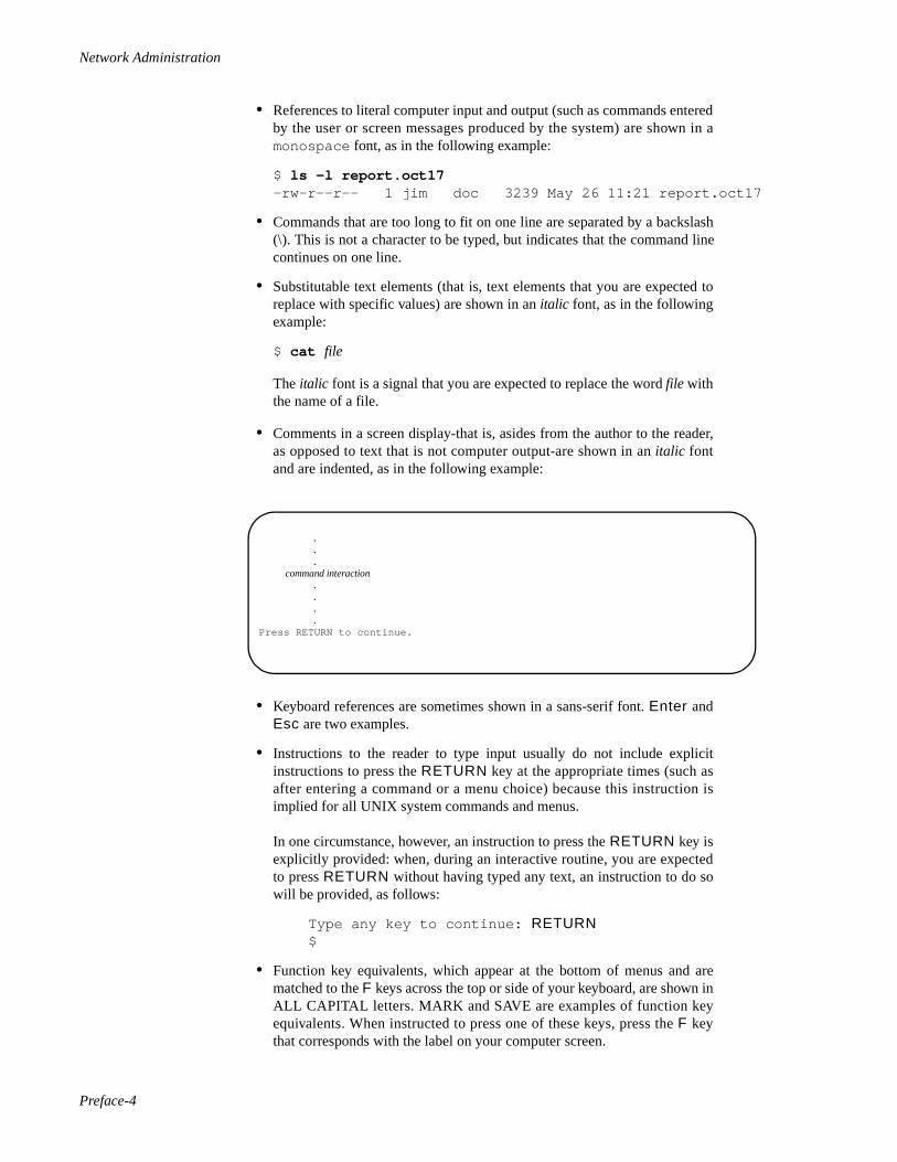
• Comments in a screen display-that is, asides from the author to the reader,as opposed to text that is not computer output-are shown in an italic fontand are indented, as in the following example:
• Keyboard references are sometimes shown in a sans-serif font. Enter andEsc are two examples.
• Instructions to the reader to type input usually do not include explicitinstructions to press the RETURN key at the appropriate times (such asafter entering a command or a menu choice) because this instruction isimplied for all UNIX system commands and menus.
In one circumstance, however, an instruction to press the RETURN key isexplicitly provided: when, during an interactive routine, you are expectedto press RETURN without having typed any text, an instruction to do sowill be provided, as follows:
Type any key to continue: RETURN$
• Function key equivalents, which appear at the bottom of menus and arematched to the F keys across the top or side of your keyboard, are shown inALL CAPITAL letters. MARK and SAVE are examples of function keyequivalents. When instructed to press one of these keys, press the F keythat corresponds with the label on your computer screen.
.
.
.command interaction
.
.
.
.Press RETURN to continue.
Preface
Preface-5
• Control characters are shown by the string CTRL-char where char is acharacter such as “d” in the control character CTRL-d. To enter a controlcharacter, hold down the CTRL key and press the letter shown. Be sure totype the letter exactly as specified: when a lowercase letter is shown (suchas the “d” in the example above), enter that lowercase letter. If a characteris shown in uppercase (such as CTRL-D), you should enter an uppercaseletter.
• The system prompt signs shown in examples of interactive sessions are thestandard default prompt signs :
- the dollar sign ($) for an ordinary user
- the pound sign (#) for the owner of the root login
Manual Pages
On-line manual pages can be viewed using the man command. References in text to “seemanual page in xxx Reference Manual” implies displaying the applicable manual pageusing the man command. For example, entering “man cat ” will display the cat(8)manual page on your terminal.

Network Administration
Preface-6
vii
Contents
Part 1 Network Services Administration
Chapter 1 Introduction to Network Services Administration
An Overview of Network Services Administration. . . . . . . . . . . . . . . . . . . . . . . . . . 1-1A Model of Network Administration . . . . . . . . . . . . . . . . . . . . . . . . . . . . . . . . . . . . 1-1Networking Facilities. . . . . . . . . . . . . . . . . . . . . . . . . . . . . . . . . . . . . . . . . . . . . . . . . 1-2Procedural Overview of BNU and REXEC Administration . . . . . . . . . . . . . . . . . . . 1-5
Set Up the Network Administrator's Login . . . . . . . . . . . . . . . . . . . . . . . . . . . . 1-5Step 1: Set Up Network Selection . . . . . . . . . . . . . . . . . . . . . . . . . . . . . . . . . . . 1-5Step 2: Set Up Name-to-Address Mapping . . . . . . . . . . . . . . . . . . . . . . . . . . . . 1-6Step 3: Set Up the listen Port Monitor . . . . . . . . . . . . . . . . . . . . . . . . . . . . . . . . 1-6Step 4: Set Up the Connection Server . . . . . . . . . . . . . . . . . . . . . . . . . . . . . . . . 1-6Step 5: Set Up the cr1 Authentication Scheme . . . . . . . . . . . . . . . . . . . . . . . . . 1-7Step 6: Setting Up ID Mapping . . . . . . . . . . . . . . . . . . . . . . . . . . . . . . . . . . . . . 1-7Step 7: Set Up BNU . . . . . . . . . . . . . . . . . . . . . . . . . . . . . . . . . . . . . . . . . . . . . . 1-8Step 8: Set up REXEC . . . . . . . . . . . . . . . . . . . . . . . . . . . . . . . . . . . . . . . . . . . . 1-8
Using the sysadm Menu Interface . . . . . . . . . . . . . . . . . . . . . . . . . . . . . . . . . . . . . . . 1-9
Chapter 2 Administering Network Selection
Introduction to Network Selection Administration . . . . . . . . . . . . . . . . . . . . . . . . . . 2-1Network Selection Overview. . . . . . . . . . . . . . . . . . . . . . . . . . . . . . . . . . . . . . . . . . . 2-2The /etc/netconfig File. . . . . . . . . . . . . . . . . . . . . . . . . . . . . . . . . . . . . . . . . . . . . . . . 2-3The NETPATH Environment Variable. . . . . . . . . . . . . . . . . . . . . . . . . . . . . . . . . . . . 2-6
Chapter 3 Administering Name-to-Address Mapping
Introduction to Name-to-Address Mapping Administration . . . . . . . . . . . . . . . . . . . 3-1The tcpip.so Library . . . . . . . . . . . . . . . . . . . . . . . . . . . . . . . . . . . . . . . . . . . . . . 3-2The tcip_nis.so Library. . . . . . . . . . . . . . . . . . . . . . . . . . . . . . . . . . . . . . . . . . . . 3-3The resolv.so Library . . . . . . . . . . . . . . . . . . . . . . . . . . . . . . . . . . . . . . . . . . . . . 3-3The straddr.so Library . . . . . . . . . . . . . . . . . . . . . . . . . . . . . . . . . . . . . . . . . . . . 3-3
Chapter 4 Administering the Connection Server
Introduction to Connection Server Administration . . . . . . . . . . . . . . . . . . . . . . . . . . 4-1The Connection Server Application Interface . . . . . . . . . . . . . . . . . . . . . . . . . . . . . . 4-2Connection Server Administration . . . . . . . . . . . . . . . . . . . . . . . . . . . . . . . . . . . . . . 4-2
Server Machine Administration . . . . . . . . . . . . . . . . . . . . . . . . . . . . . . . . . . . . . 4-2Registering Authentication Schemes . . . . . . . . . . . . . . . . . . . . . . . . . . . . . 4-2
Client Machine Administration . . . . . . . . . . . . . . . . . . . . . . . . . . . . . . . . . . . . . 4-3Maintaining the /etc/iaf/serve.allow File. . . . . . . . . . . . . . . . . . . . . . . . . . . 4-3Maintaining the /etc/iaf/serve.alias File . . . . . . . . . . . . . . . . . . . . . . . . . . . 4-4
Network Administration
viii
Setting Up LIDAUTH.map . . . . . . . . . . . . . . . . . . . . . . . . . . . . . . . . . . . . . 4-4Examples . . . . . . . . . . . . . . . . . . . . . . . . . . . . . . . . . . . . . . . . . . . . . . . . . . . 4-6
The reportscheme Service. . . . . . . . . . . . . . . . . . . . . . . . . . . . . . . . . . . . . . . . . . 4-7The Connection Server Authentication Scheme File . . . . . . . . . . . . . . . . . . . . . 4-8The Connection Server Log File. . . . . . . . . . . . . . . . . . . . . . . . . . . . . . . . . . . . . 4-9The Connection Server Debug File. . . . . . . . . . . . . . . . . . . . . . . . . . . . . . . . . . . 4-10
Chapter 5 cr1 Bilateral Authentication Scheme
Introduction to the cr1 Bilateral Authentication Scheme. . . . . . . . . . . . . . . . . . . . . . 5-1An Overview of cr1 Administration. . . . . . . . . . . . . . . . . . . . . . . . . . . . . . . . . . . . . . 5-3Registering cr1 with a Port Monitor. . . . . . . . . . . . . . . . . . . . . . . . . . . . . . . . . . . . . . 5-6Registering cr1 with the Connection Server . . . . . . . . . . . . . . . . . . . . . . . . . . . . . . . 5-6Managing the Daemon and the Master Key. . . . . . . . . . . . . . . . . . . . . . . . . . . . . . . . 5-7
Starting and Stopping the Daemon . . . . . . . . . . . . . . . . . . . . . . . . . . . . . . . . . . . 5-7Creating a Master Key . . . . . . . . . . . . . . . . . . . . . . . . . . . . . . . . . . . . . . . . . . . . 5-8
Setting Up the Key Database . . . . . . . . . . . . . . . . . . . . . . . . . . . . . . . . . . . . . . . . . . . 5-8
Chapter 6 Administering ID Mapping
Introduction to ID Mapping Administration . . . . . . . . . . . . . . . . . . . . . . . . . . . . . . . 6-1Setting Up Login Maps . . . . . . . . . . . . . . . . . . . . . . . . . . . . . . . . . . . . . . . . . . . . . . . 6-5
Administering an idata File. . . . . . . . . . . . . . . . . . . . . . . . . . . . . . . . . . . . . . . . . 6-6Setting Up the idata File . . . . . . . . . . . . . . . . . . . . . . . . . . . . . . . . . . . . . . . 6-7Adding an Entry to an idata File . . . . . . . . . . . . . . . . . . . . . . . . . . . . . . . . . 6-8Examples . . . . . . . . . . . . . . . . . . . . . . . . . . . . . . . . . . . . . . . . . . . . . . . . . . . 6-9Deleting an Entry in an idata File . . . . . . . . . . . . . . . . . . . . . . . . . . . . . . . . 6-10Deleting the idata and uidata Files . . . . . . . . . . . . . . . . . . . . . . . . . . . . . . . 6-10Checking Files and Fixing File Inconsistencies . . . . . . . . . . . . . . . . . . . . . 6-11Displaying Information . . . . . . . . . . . . . . . . . . . . . . . . . . . . . . . . . . . . . . . . 6-12
Administering a uidata File. . . . . . . . . . . . . . . . . . . . . . . . . . . . . . . . . . . . . . . . . 6-12Setting Up the uidata File . . . . . . . . . . . . . . . . . . . . . . . . . . . . . . . . . . . . . . 6-13Enabling and Disabling User-Controlled Mapping . . . . . . . . . . . . . . . . . . . 6-14Adding an Entry to a uidata File . . . . . . . . . . . . . . . . . . . . . . . . . . . . . . . . . 6-14Deleting an Entry in a uidata File . . . . . . . . . . . . . . . . . . . . . . . . . . . . . . . . 6-15Checking Files and Fixing File Inconsistencies . . . . . . . . . . . . . . . . . . . . . 6-15Displaying Information . . . . . . . . . . . . . . . . . . . . . . . . . . . . . . . . . . . . . . . . 6-16
Setting Up Attribute Maps . . . . . . . . . . . . . . . . . . . . . . . . . . . . . . . . . . . . . . . . . . . . . 6-16Setting Up an Attribute Map. . . . . . . . . . . . . . . . . . . . . . . . . . . . . . . . . . . . . . . . 6-18Adding an Entry to an Attribute Map . . . . . . . . . . . . . . . . . . . . . . . . . . . . . . . . . 6-18
Examples . . . . . . . . . . . . . . . . . . . . . . . . . . . . . . . . . . . . . . . . . . . . . . . . . . . 6-19Deleting an Entry in an Attribute Map . . . . . . . . . . . . . . . . . . . . . . . . . . . . . . . . 6-20Deleting an Attribute Map . . . . . . . . . . . . . . . . . . . . . . . . . . . . . . . . . . . . . . . . . 6-20Checking Files and Fixing File Inconsistencies . . . . . . . . . . . . . . . . . . . . . . . . . 6-20Displaying Information. . . . . . . . . . . . . . . . . . . . . . . . . . . . . . . . . . . . . . . . . . . . 6-21
Setting Up a LID Map on a System Running the ES Utilities. . . . . . . . . . . . . . . . . . 6-22Setting Up RLID.map . . . . . . . . . . . . . . . . . . . . . . . . . . . . . . . . . . . . . . . . . . . . . 6-22
Examples . . . . . . . . . . . . . . . . . . . . . . . . . . . . . . . . . . . . . . . . . . . . . . . . . . . 6-24
Chapter 7 Administering the Basic Networking Utilities
Introduction to Basic Networking Utilities Administration. . . . . . . . . . . . . . . . . . . . 7-1Overview of BNU . . . . . . . . . . . . . . . . . . . . . . . . . . . . . . . . . . . . . . . . . . . . . . . . . . . 7-2

Contents
ix
What BNU Does. . . . . . . . . . . . . . . . . . . . . . . . . . . . . . . . . . . . . . . . . . . . . . . . . 7-2BNU Components . . . . . . . . . . . . . . . . . . . . . . . . . . . . . . . . . . . . . . . . . . . . . . . 7-4
Networking Hardware . . . . . . . . . . . . . . . . . . . . . . . . . . . . . . . . . . . . . . . . . 7-4Networking Programs . . . . . . . . . . . . . . . . . . . . . . . . . . . . . . . . . . . . . . . . . 7-4
User Programs . . . . . . . . . . . . . . . . . . . . . . . . . . . . . . . . . . . . . . . . . . . 7-4Administrative Programs . . . . . . . . . . . . . . . . . . . . . . . . . . . . . . . . . . . 7-5Networking Daemons . . . . . . . . . . . . . . . . . . . . . . . . . . . . . . . . . . . . . 7-6The remote.unknown File . . . . . . . . . . . . . . . . . . . . . . . . . . . . . . . . . . 7-6
Networking Support Files . . . . . . . . . . . . . . . . . . . . . . . . . . . . . . . . . . . . . . 7-7BNU Administration . . . . . . . . . . . . . . . . . . . . . . . . . . . . . . . . . . . . . . . . . . . . . 7-8
Database Support Files . . . . . . . . . . . . . . . . . . . . . . . . . . . . . . . . . . . . . . . . . . . . . . . 7-9The Permissions File . . . . . . . . . . . . . . . . . . . . . . . . . . . . . . . . . . . . . . . . . . . . . 7-10
Options . . . . . . . . . . . . . . . . . . . . . . . . . . . . . . . . . . . . . . . . . . . . . . . . . . . . 7-11The Devconfig File . . . . . . . . . . . . . . . . . . . . . . . . . . . . . . . . . . . . . . . . . . . . . . . 7-18The Sysfiles File . . . . . . . . . . . . . . . . . . . . . . . . . . . . . . . . . . . . . . . . . . . . . . . . . 7-19The Limits File . . . . . . . . . . . . . . . . . . . . . . . . . . . . . . . . . . . . . . . . . . . . . . . . . . 7-19The RLID.map File . . . . . . . . . . . . . . . . . . . . . . . . . . . . . . . . . . . . . . . . . . . . . . 7-20The LIDAUTH.map File . . . . . . . . . . . . . . . . . . . . . . . . . . . . . . . . . . . . . . . . . . 7-20The Config File. . . . . . . . . . . . . . . . . . . . . . . . . . . . . . . . . . . . . . . . . . . . . . . . . . 7-21The Devices File. . . . . . . . . . . . . . . . . . . . . . . . . . . . . . . . . . . . . . . . . . . . . . . . . 7-22
Protocols . . . . . . . . . . . . . . . . . . . . . . . . . . . . . . . . . . . . . . . . . . . . . . . . . . . 7-27Serial cu Connections and the Devices File . . . . . . . . . . . . . . . . . . . . . . . . 7-28TCP/IP cu Connections and the Devices File . . . . . . . . . . . . . . . . . . . . . . . 7-28
The Dialers File . . . . . . . . . . . . . . . . . . . . . . . . . . . . . . . . . . . . . . . . . . . . . . . . . 7-29The Systems File . . . . . . . . . . . . . . . . . . . . . . . . . . . . . . . . . . . . . . . . . . . . . . . . 7-31
Serial cu Connections and the Systems File . . . . . . . . . . . . . . . . . . . . . . . . 7-37TCP/IP cu Connections and the Systems File. . . . . . . . . . . . . . . . . . . . . . . 7-38
The Dialcodes File . . . . . . . . . . . . . . . . . . . . . . . . . . . . . . . . . . . . . . . . . . . . . . . 7-38The Poll File . . . . . . . . . . . . . . . . . . . . . . . . . . . . . . . . . . . . . . . . . . . . . . . . . . . . 7-39The Grades File . . . . . . . . . . . . . . . . . . . . . . . . . . . . . . . . . . . . . . . . . . . . . . . . . 7-39
Default Grade . . . . . . . . . . . . . . . . . . . . . . . . . . . . . . . . . . . . . . . . . . . . . . . 7-41Administrative Support Files . . . . . . . . . . . . . . . . . . . . . . . . . . . . . . . . . . . . . . . . . . . 7-41Log Files . . . . . . . . . . . . . . . . . . . . . . . . . . . . . . . . . . . . . . . . . . . . . . . . . . . . . . . . . . 7-43
Command Log . . . . . . . . . . . . . . . . . . . . . . . . . . . . . . . . . . . . . . . . . . . . . . . . . . 7-44System History Log . . . . . . . . . . . . . . . . . . . . . . . . . . . . . . . . . . . . . . . . . . . . . . 7-45Error Log . . . . . . . . . . . . . . . . . . . . . . . . . . . . . . . . . . . . . . . . . . . . . . . . . . . . . . 7-46Transfer Log . . . . . . . . . . . . . . . . . . . . . . . . . . . . . . . . . . . . . . . . . . . . . . . . . . . . 7-47
Report Statistics of File Transfer. . . . . . . . . . . . . . . . . . . . . . . . . . . . . . . . . 7-48Accounting Log . . . . . . . . . . . . . . . . . . . . . . . . . . . . . . . . . . . . . . . . . . . . . . . . . 7-49Security Log . . . . . . . . . . . . . . . . . . . . . . . . . . . . . . . . . . . . . . . . . . . . . . . . . . . . 7-50
File Transfer (xfer) Security Log . . . . . . . . . . . . . . . . . . . . . . . . . . . . . . . . 7-50Remote Execution (rexe) Security Log . . . . . . . . . . . . . . . . . . . . . . . . . . . . 7-51
Performance Log . . . . . . . . . . . . . . . . . . . . . . . . . . . . . . . . . . . . . . . . . . . . . . . . 7-52Connection (conn) Performance Log . . . . . . . . . . . . . . . . . . . . . . . . . . . . . 7-53File Transfer (xfer) Performance Log . . . . . . . . . . . . . . . . . . . . . . . . . . . . . 7-54
Foreign Log . . . . . . . . . . . . . . . . . . . . . . . . . . . . . . . . . . . . . . . . . . . . . . . . . . . . 7-56Adding uucp Logins . . . . . . . . . . . . . . . . . . . . . . . . . . . . . . . . . . . . . . . . . . . . . . . . . 7-56BNU Setup Procedures . . . . . . . . . . . . . . . . . . . . . . . . . . . . . . . . . . . . . . . . . . . . . . . 7-57
(1) For All Types of Connection. . . . . . . . . . . . . . . . . . . . . . . . . . . . . . . . . . . . . 7-57(2a) For Connections Using the New CS Dialer Type - the Client Machine . . . 7-58
Essential Steps. . . . . . . . . . . . . . . . . . . . . . . . . . . . . . . . . . . . . . . . . . . . . . . 7-58Optional or Conditional Steps. . . . . . . . . . . . . . . . . . . . . . . . . . . . . . . . . . . 7-58
(2b) For Connections Using the New CS Dialer Type - the Server Machine. . . 7-59Essential Steps. . . . . . . . . . . . . . . . . . . . . . . . . . . . . . . . . . . . . . . . . . . . . . . 7-59
Network Administration
x
Optional or Conditional Steps . . . . . . . . . . . . . . . . . . . . . . . . . . . . . . . . . . . 7-60(3a) For Connections Not Using the CS Dialer Type- the Client Machine . . . . 7-61
Optional or Conditional Steps . . . . . . . . . . . . . . . . . . . . . . . . . . . . . . . . . . . 7-61(3b) For Connections Not Using the CS Dialer Type - the Server Machine. . . . 7-62
Optional or Conditional Steps . . . . . . . . . . . . . . . . . . . . . . . . . . . . . . . . . . . 7-62BNU Maintenance . . . . . . . . . . . . . . . . . . . . . . . . . . . . . . . . . . . . . . . . . . . . . . . . . . . 7-63
Automated Networking Maintenance (cron) . . . . . . . . . . . . . . . . . . . . . . . . . . . 7-63uudemon.poll . . . . . . . . . . . . . . . . . . . . . . . . . . . . . . . . . . . . . . . . . . . . . . . . 7-63uudemon.hour . . . . . . . . . . . . . . . . . . . . . . . . . . . . . . . . . . . . . . . . . . . . . . . 7-64uudemon.admin . . . . . . . . . . . . . . . . . . . . . . . . . . . . . . . . . . . . . . . . . . . . . . 7-64uudemon.clean. . . . . . . . . . . . . . . . . . . . . . . . . . . . . . . . . . . . . . . . . . . . . . . 7-65
Manual Maintenance. . . . . . . . . . . . . . . . . . . . . . . . . . . . . . . . . . . . . . . . . . . . . . 7-65Cleaning Up Log Files. . . . . . . . . . . . . . . . . . . . . . . . . . . . . . . . . . . . . . . . . 7-65
BNU Debugging. . . . . . . . . . . . . . . . . . . . . . . . . . . . . . . . . . . . . . . . . . . . . . . . . . . . . 7-66Check Basic Information . . . . . . . . . . . . . . . . . . . . . . . . . . . . . . . . . . . . . . . . . . 7-67Check for Faulty ACU/Modem. . . . . . . . . . . . . . . . . . . . . . . . . . . . . . . . . . . . . . 7-67Check Systems File. . . . . . . . . . . . . . . . . . . . . . . . . . . . . . . . . . . . . . . . . . . . . . . 7-67Debug Transmissions . . . . . . . . . . . . . . . . . . . . . . . . . . . . . . . . . . . . . . . . . . . . . 7-67
Chapter 8 Administering REXEC
Introduction to REXEC Administration . . . . . . . . . . . . . . . . . . . . . . . . . . . . . . . . . . 8-1Overview of REXEC Administration . . . . . . . . . . . . . . . . . . . . . . . . . . . . . . . . . . . . 8-2Registering REXEC with a Port Monitor. . . . . . . . . . . . . . . . . . . . . . . . . . . . . . . . . . 8-3Adding and Removing Services. . . . . . . . . . . . . . . . . . . . . . . . . . . . . . . . . . . . . . . . . 8-4
Adding a Service. . . . . . . . . . . . . . . . . . . . . . . . . . . . . . . . . . . . . . . . . . . . . . . . . 8-4Examples . . . . . . . . . . . . . . . . . . . . . . . . . . . . . . . . . . . . . . . . . . . . . . . . . . . 8-5
Removing a Service . . . . . . . . . . . . . . . . . . . . . . . . . . . . . . . . . . . . . . . . . . . . . . 8-6Example . . . . . . . . . . . . . . . . . . . . . . . . . . . . . . . . . . . . . . . . . . . . . . . . . . . . 8-6
Listing Defined Services . . . . . . . . . . . . . . . . . . . . . . . . . . . . . . . . . . . . . . . . . . . . . . 8-6Linking Services to REXEC . . . . . . . . . . . . . . . . . . . . . . . . . . . . . . . . . . . . . . . . . . . 8-7
Part 2 Mail Service Administration
Chapter 9 Administering the Mail Service
Introduction to Mail Service Administration . . . . . . . . . . . . . . . . . . . . . . . . . . . . . . . 9-1Multilevel Mail Files . . . . . . . . . . . . . . . . . . . . . . . . . . . . . . . . . . . . . . . . . . . . . . . . . 9-1Mail Administration Files . . . . . . . . . . . . . . . . . . . . . . . . . . . . . . . . . . . . . . . . . . . . . 9-2
Editing Mail Administration Files in a Secure Environment . . . . . . . . . . . . . . . 9-2Mail Addressing Styles. . . . . . . . . . . . . . . . . . . . . . . . . . . . . . . . . . . . . . . . . . . . 9-3
Establishing a Smarter Host. . . . . . . . . . . . . . . . . . . . . . . . . . . . . . . . . . . . . . . . . . . . 9-3Establishing Domain Addresses. . . . . . . . . . . . . . . . . . . . . . . . . . . . . . . . . . . . . . . . . 9-4Establishing a Mail Cluster or Gateway. . . . . . . . . . . . . . . . . . . . . . . . . . . . . . . . . . . 9-4Establishing Mail Service on a Networked File System . . . . . . . . . . . . . . . . . . . . . . 9-5Administering alias Lists . . . . . . . . . . . . . . . . . . . . . . . . . . . . . . . . . . . . . . . . . . . . . . 9-6NIS and Mail Aliases . . . . . . . . . . . . . . . . . . . . . . . . . . . . . . . . . . . . . . . . . . . . . . . . . 9-7Surrogate Files . . . . . . . . . . . . . . . . . . . . . . . . . . . . . . . . . . . . . . . . . . . . . . . . . . . . . . 9-7
Logging Mail . . . . . . . . . . . . . . . . . . . . . . . . . . . . . . . . . . . . . . . . . . . . . . . . . . . 9-7Using pathrouter for Smart Routing . . . . . . . . . . . . . . . . . . . . . . . . . . . . . . . . . . 9-8Controlling Mail Resource Access . . . . . . . . . . . . . . . . . . . . . . . . . . . . . . . . . . . 9-8
Administering SMTP . . . . . . . . . . . . . . . . . . . . . . . . . . . . . . . . . . . . . . . . . . . . . . . . . 9-9

Contents
xi
Setting Up SMTP to Listen Over Multiple Networks . . . . . . . . . . . . . . . . . . . . 9-10The mailR Language and Header Rewriting . . . . . . . . . . . . . . . . . . . . . . . . . . . . . . . 9-11The localmail Command . . . . . . . . . . . . . . . . . . . . . . . . . . . . . . . . . . . . . . . . . . . . . . 9-14MIME, Metamail, and /etc/mail/mailcap . . . . . . . . . . . . . . . . . . . . . . . . . . . . . . . . . 9-15Locales and Character Sets . . . . . . . . . . . . . . . . . . . . . . . . . . . . . . . . . . . . . . . . . . . . 9-17
Chapter 10 Sendmail
Introduction to Sendmail . . . . . . . . . . . . . . . . . . . . . . . . . . . . . . . . . . . . . . . . . . . . . . 10-1Mail vs. Sendmail . . . . . . . . . . . . . . . . . . . . . . . . . . . . . . . . . . . . . . . . . . . . . . . . . . . 10-1Sendmail Aliases . . . . . . . . . . . . . . . . . . . . . . . . . . . . . . . . . . . . . . . . . . . . . . . . . . . . 10-1
Rebuilding the Sendmail Alias Database . . . . . . . . . . . . . . . . . . . . . . . . . . . . . . 10-2NIS and Sendmail Aliases . . . . . . . . . . . . . . . . . . . . . . . . . . . . . . . . . . . . . . . . . 10-2Pre-User Forwarding . . . . . . . . . . . . . . . . . . . . . . . . . . . . . . . . . . . . . . . . . . . . . 10-3
Sendmail Configuration File . . . . . . . . . . . . . . . . . . . . . . . . . . . . . . . . . . . . . . . . . . . 10-3Configuration File Syntax and Semantics . . . . . . . . . . . . . . . . . . . . . . . . . . . . . . . . . 10-3The Syntax. . . . . . . . . . . . . . . . . . . . . . . . . . . . . . . . . . . . . . . . . . . . . . . . . . . . . . . . . 10-3
R and S - Rewriting Rules . . . . . . . . . . . . . . . . . . . . . . . . . . . . . . . . . . . . . . . . . 10-4D - Define Macro . . . . . . . . . . . . . . . . . . . . . . . . . . . . . . . . . . . . . . . . . . . . . . . . 10-4C and F - Define Classes . . . . . . . . . . . . . . . . . . . . . . . . . . . . . . . . . . . . . . . . . . 10-4M - Define Mailer. . . . . . . . . . . . . . . . . . . . . . . . . . . . . . . . . . . . . . . . . . . . . . . . 10-5H - Define Header . . . . . . . . . . . . . . . . . . . . . . . . . . . . . . . . . . . . . . . . . . . . . . . 10-5O - Set Option. . . . . . . . . . . . . . . . . . . . . . . . . . . . . . . . . . . . . . . . . . . . . . . . . . . 10-6T - Define Trusted Users . . . . . . . . . . . . . . . . . . . . . . . . . . . . . . . . . . . . . . . . . . 10-6Precedence Definitions . . . . . . . . . . . . . . . . . . . . . . . . . . . . . . . . . . . . . . . . . . . . 10-6
The Semantics . . . . . . . . . . . . . . . . . . . . . . . . . . . . . . . . . . . . . . . . . . . . . . . . . . . . . . 10-6Special Macros, Conditionals. . . . . . . . . . . . . . . . . . . . . . . . . . . . . . . . . . . . . . . 10-7Special Classes . . . . . . . . . . . . . . . . . . . . . . . . . . . . . . . . . . . . . . . . . . . . . . . . . . 10-8
The Left Hand Side . . . . . . . . . . . . . . . . . . . . . . . . . . . . . . . . . . . . . . . . . . . 10-9The Right Hand Side . . . . . . . . . . . . . . . . . . . . . . . . . . . . . . . . . . . . . . . . . . 10-9
Semantics Of Rewriting Rule Sets . . . . . . . . . . . . . . . . . . . . . . . . . . . . . . . . . . . 10-10Mailer Flags etc . . . . . . . . . . . . . . . . . . . . . . . . . . . . . . . . . . . . . . . . . . . . . . . . . 10-11The error Mailer . . . . . . . . . . . . . . . . . . . . . . . . . . . . . . . . . . . . . . . . . . . . . . . . . 10-12
Building a Configuration File . . . . . . . . . . . . . . . . . . . . . . . . . . . . . . . . . . . . . . . . . . 10-13Purpose . . . . . . . . . . . . . . . . . . . . . . . . . . . . . . . . . . . . . . . . . . . . . . . . . . . . . . . . 10-13Philosophy . . . . . . . . . . . . . . . . . . . . . . . . . . . . . . . . . . . . . . . . . . . . . . . . . . . . . 10-13
Large Site, Many Hosts - Minimum Information . . . . . . . . . . . . . . . . . . . . 10-13Small Site - Complete Information . . . . . . . . . . . . . . . . . . . . . . . . . . . . . . . 10-14Single Host . . . . . . . . . . . . . . . . . . . . . . . . . . . . . . . . . . . . . . . . . . . . . . . . . 10-14
Relevant Issues . . . . . . . . . . . . . . . . . . . . . . . . . . . . . . . . . . . . . . . . . . . . . . . . . . 10-14How To Proceed . . . . . . . . . . . . . . . . . . . . . . . . . . . . . . . . . . . . . . . . . . . . . . . . . 10-15Testing The Rewriting Rules - The -bt Flag . . . . . . . . . . . . . . . . . . . . . . . . . . . . 10-15Building Mailer Descriptions . . . . . . . . . . . . . . . . . . . . . . . . . . . . . . . . . . . . . . . 10-16
Enabling Sendmail. . . . . . . . . . . . . . . . . . . . . . . . . . . . . . . . . . . . . . . . . . . . . . . . . . . 10-18Sendmail Utilities . . . . . . . . . . . . . . . . . . . . . . . . . . . . . . . . . . . . . . . . . . . . . . . . . . . 10-18Sendmail Mail Queue . . . . . . . . . . . . . . . . . . . . . . . . . . . . . . . . . . . . . . . . . . . . . . . . 10-19Sendmail Log. . . . . . . . . . . . . . . . . . . . . . . . . . . . . . . . . . . . . . . . . . . . . . . . . . . . . . . 10-19
Network Administration
xii
Part 3 TCP/IP Network Administration
Chapter 11 Introduction to Administering TCP/IP Networks
About TCP/IP Network Administration . . . . . . . . . . . . . . . . . . . . . . . . . . . . . . . . . . 11-1How This Part is Organized . . . . . . . . . . . . . . . . . . . . . . . . . . . . . . . . . . . . . . . . 11-1
Introducing the Internet Protocol Suite . . . . . . . . . . . . . . . . . . . . . . . . . . . . . . . . . . . 11-2Physical Layer. . . . . . . . . . . . . . . . . . . . . . . . . . . . . . . . . . . . . . . . . . . . . . . . . . . 11-3Data Link Layer . . . . . . . . . . . . . . . . . . . . . . . . . . . . . . . . . . . . . . . . . . . . . . . . . 11-4Network Layer . . . . . . . . . . . . . . . . . . . . . . . . . . . . . . . . . . . . . . . . . . . . . . . . . . 11-4Transport Layer. . . . . . . . . . . . . . . . . . . . . . . . . . . . . . . . . . . . . . . . . . . . . . . . . . 11-4Application Layer . . . . . . . . . . . . . . . . . . . . . . . . . . . . . . . . . . . . . . . . . . . . . . . . 11-5
Telnet . . . . . . . . . . . . . . . . . . . . . . . . . . . . . . . . . . . . . . . . . . . . . . . . . . . . . . 11-5FTP . . . . . . . . . . . . . . . . . . . . . . . . . . . . . . . . . . . . . . . . . . . . . . . . . . . . . . . 11-5Domain Name Service. . . . . . . . . . . . . . . . . . . . . . . . . . . . . . . . . . . . . . . . . 11-5Other Application Layer Protocols . . . . . . . . . . . . . . . . . . . . . . . . . . . . . . . 11-6
TCP/IP Concepts . . . . . . . . . . . . . . . . . . . . . . . . . . . . . . . . . . . . . . . . . . . . . . . . . . . . 11-6IP Addresses and Domain Names. . . . . . . . . . . . . . . . . . . . . . . . . . . . . . . . . . . . 11-6
IP Addresses . . . . . . . . . . . . . . . . . . . . . . . . . . . . . . . . . . . . . . . . . . . . . . . . 11-6Network ID. . . . . . . . . . . . . . . . . . . . . . . . . . . . . . . . . . . . . . . . . . . . . . 11-7Network Classes . . . . . . . . . . . . . . . . . . . . . . . . . . . . . . . . . . . . . . . . . . 11-7Host ID . . . . . . . . . . . . . . . . . . . . . . . . . . . . . . . . . . . . . . . . . . . . . . . . . 11-8Subnet ID . . . . . . . . . . . . . . . . . . . . . . . . . . . . . . . . . . . . . . . . . . . . . . . 11-9
Domain Names . . . . . . . . . . . . . . . . . . . . . . . . . . . . . . . . . . . . . . . . . . . . . . . . . . 11-9Organization of Internet Domains . . . . . . . . . . . . . . . . . . . . . . . . . . . . . . . . 11-10Selecting a Domain Name . . . . . . . . . . . . . . . . . . . . . . . . . . . . . . . . . . . . . . 11-12Registering Your Domain . . . . . . . . . . . . . . . . . . . . . . . . . . . . . . . . . . . . . . 11-13
Chapter 12 Setting Up TCP/IP
Introduction to TCP/IP Setup. . . . . . . . . . . . . . . . . . . . . . . . . . . . . . . . . . . . . . . . . . . 12-1Planning Your TCP/IP Network. . . . . . . . . . . . . . . . . . . . . . . . . . . . . . . . . . . . . . . . . 12-1
Choosing Networking Media . . . . . . . . . . . . . . . . . . . . . . . . . . . . . . . . . . . . . . . 12-1Getting an IP Network Number and Domain Name. . . . . . . . . . . . . . . . . . . . . . 12-1
IP addresses . . . . . . . . . . . . . . . . . . . . . . . . . . . . . . . . . . . . . . . . . . . . . . . . . 12-2Domain Names and System Names. . . . . . . . . . . . . . . . . . . . . . . . . . . . . . . 12-2
Installing TCP/IP . . . . . . . . . . . . . . . . . . . . . . . . . . . . . . . . . . . . . . . . . . . . . . . . . . . . 12-3Creating a Simple TCP/IP Network. . . . . . . . . . . . . . . . . . . . . . . . . . . . . . . . . . . . . . 12-3Expanding Your TCP/IP Network . . . . . . . . . . . . . . . . . . . . . . . . . . . . . . . . . . . . . . . 12-5
Setting Up Serial Connections . . . . . . . . . . . . . . . . . . . . . . . . . . . . . . . . . . . . . . 12-5Configuring Point-to-Point Protocol Connections (PPP) . . . . . . . . . . . . . . 12-5
Configuring SystemA (incoming ppp connection). . . . . . . . . . . . . . . . 12-6Configuring SystemB (outgoing ppp connection) . . . . . . . . . . . . . . . . 12-16
Configuring Serial Line IP Connections (SLIP) . . . . . . . . . . . . . . . . . . . . . 12-20Enabling SLIP Connections . . . . . . . . . . . . . . . . . . . . . . . . . . . . . . . . . 12-20Disabling SLIP Connections . . . . . . . . . . . . . . . . . . . . . . . . . . . . . . . . 12-20
Setting Up Routing . . . . . . . . . . . . . . . . . . . . . . . . . . . . . . . . . . . . . . . . . . . . . . . 12-21Setting Up Domain Name Service . . . . . . . . . . . . . . . . . . . . . . . . . . . . . . . . . . . 12-22Setting Up Subnetworks . . . . . . . . . . . . . . . . . . . . . . . . . . . . . . . . . . . . . . . . . . . 12-22Changing Available Services . . . . . . . . . . . . . . . . . . . . . . . . . . . . . . . . . . . . . . . 12-23Managing Remote Systems . . . . . . . . . . . . . . . . . . . . . . . . . . . . . . . . . . . . . . . . 12-24Synchronizing Time . . . . . . . . . . . . . . . . . . . . . . . . . . . . . . . . . . . . . . . . . . . . . . 12-24Maintaining Security. . . . . . . . . . . . . . . . . . . . . . . . . . . . . . . . . . . . . . . . . . . . . . 12-24
Contents
xiii
Administering the hosts.equiv and .rhosts Files . . . . . . . . . . . . . . . . . . . . . 12-24The /etc/hosts.equiv File . . . . . . . . . . . . . . . . . . . . . . . . . . . . . . . . . . . . . . . 12-25
Example . . . . . . . . . . . . . . . . . . . . . . . . . . . . . . . . . . . . . . . . . . . . . . . . 12-26The .rhosts File. . . . . . . . . . . . . . . . . . . . . . . . . . . . . . . . . . . . . . . . . . . 12-26Example 1 . . . . . . . . . . . . . . . . . . . . . . . . . . . . . . . . . . . . . . . . . . . . . . 12-27Example 2 . . . . . . . . . . . . . . . . . . . . . . . . . . . . . . . . . . . . . . . . . . . . . . 12-27
Security Issues. . . . . . . . . . . . . . . . . . . . . . . . . . . . . . . . . . . . . . . . . . . . . . . 12-28Disabling the TCP/IP Network Services. . . . . . . . . . . . . . . . . . . . . . . . . . . 12-28
TCP/IP Services and Enhanced Security Issues. . . . . . . . . . . . . . . . . . . . . . . . . 12-29Minimizing TCP/IP Security Risks. . . . . . . . . . . . . . . . . . . . . . . . . . . . . . . 12-29TCP/IP and Secure Device Handling . . . . . . . . . . . . . . . . . . . . . . . . . . . . . 12-29SYS_PRIVATE and USER_LOGIN Security Levels . . . . . . . . . . . . . . . . . 12-30
Setting Up the Network Administrator's Login . . . . . . . . . . . . . . . . . . 12-30SYS_PRIVATE Level Executables . . . . . . . . . . . . . . . . . . . . . . . . . . . 12-30USER_LOGIN Level Executables. . . . . . . . . . . . . . . . . . . . . . . . . . . . 12-31SYS_PUBLIC-level Files . . . . . . . . . . . . . . . . . . . . . . . . . . . . . . . . . . 12-31
Chapter 13 Setting Up Routers and Subnetworks
Introduction to Router and Subnetwork Administration . . . . . . . . . . . . . . . . . . . . . . 13-1Configuring Routing . . . . . . . . . . . . . . . . . . . . . . . . . . . . . . . . . . . . . . . . . . . . . . . . . 13-1
Using the routed Daemon. . . . . . . . . . . . . . . . . . . . . . . . . . . . . . . . . . . . . . . . . . 13-2Preparing for Routing. . . . . . . . . . . . . . . . . . . . . . . . . . . . . . . . . . . . . . . . . . . . . 13-2Options for the Generic configure Command . . . . . . . . . . . . . . . . . . . . . . . . . . 13-5
Configuring Multiple Network Cards . . . . . . . . . . . . . . . . . . . . . . . . . . . . . 13-6Configuring the First Network Device. . . . . . . . . . . . . . . . . . . . . . . . . 13-6Configuring the Next Network Device . . . . . . . . . . . . . . . . . . . . . . . . 13-9Configuring the System as a Gateway . . . . . . . . . . . . . . . . . . . . . . . . . 13-11Sample Router Files . . . . . . . . . . . . . . . . . . . . . . . . . . . . . . . . . . . . . . . 13-11
Setting up the Route Daemon. . . . . . . . . . . . . . . . . . . . . . . . . . . . . . . . . . . . . . . 13-12Setting Up Router Clients. . . . . . . . . . . . . . . . . . . . . . . . . . . . . . . . . . . . . . . . . . 13-14
Specifying a Default Router . . . . . . . . . . . . . . . . . . . . . . . . . . . . . . . . . . . . 13-15Using Specific Routers . . . . . . . . . . . . . . . . . . . . . . . . . . . . . . . . . . . . . . . . 13-16Running the Route Daemon on a Client . . . . . . . . . . . . . . . . . . . . . . . . . . . 13-17
Setting Up Subnets . . . . . . . . . . . . . . . . . . . . . . . . . . . . . . . . . . . . . . . . . . . . . . . 13-17Network Masks . . . . . . . . . . . . . . . . . . . . . . . . . . . . . . . . . . . . . . . . . . . . . . 13-18Changing to a Subnetted Network . . . . . . . . . . . . . . . . . . . . . . . . . . . . . . . 13-19
Examples of Subnets . . . . . . . . . . . . . . . . . . . . . . . . . . . . . . . . . . . . . . 13-19
Chapter 14 Managing TCP/IP Nodes Using SNMP
Introduction to SNMP Administration . . . . . . . . . . . . . . . . . . . . . . . . . . . . . . . . . . . 14-1SNMP History . . . . . . . . . . . . . . . . . . . . . . . . . . . . . . . . . . . . . . . . . . . . . . . . . . . . . . 14-1Basic SNMP Concepts. . . . . . . . . . . . . . . . . . . . . . . . . . . . . . . . . . . . . . . . . . . . . . . . 14-2
SNMP Protocol. . . . . . . . . . . . . . . . . . . . . . . . . . . . . . . . . . . . . . . . . . . . . . . . . . 14-2Structure of Management Information (SMI) . . . . . . . . . . . . . . . . . . . . . . . . . . 14-2Management Information Base (MIB) . . . . . . . . . . . . . . . . . . . . . . . . . . . . . . . . 14-3Agents and Management Stations . . . . . . . . . . . . . . . . . . . . . . . . . . . . . . . . . . . 14-4Traps . . . . . . . . . . . . . . . . . . . . . . . . . . . . . . . . . . . . . . . . . . . . . . . . . . . . . . . . . . 14-4Authentication . . . . . . . . . . . . . . . . . . . . . . . . . . . . . . . . . . . . . . . . . . . . . . . . . . 14-4
Overview of SNMP . . . . . . . . . . . . . . . . . . . . . . . . . . . . . . . . . . . . . . . . . . . . . . . . . . 14-5Configuring the SNMP Agent . . . . . . . . . . . . . . . . . . . . . . . . . . . . . . . . . . . . . . . . . . 14-6Using the SNMP Commands. . . . . . . . . . . . . . . . . . . . . . . . . . . . . . . . . . . . . . . . . . . 14-7
Network Administration
xiv
getone Command . . . . . . . . . . . . . . . . . . . . . . . . . . . . . . . . . . . . . . . . . . . . . . . . 14-8getid Command. . . . . . . . . . . . . . . . . . . . . . . . . . . . . . . . . . . . . . . . . . . . . . . . . . 14-8getmany Command . . . . . . . . . . . . . . . . . . . . . . . . . . . . . . . . . . . . . . . . . . . . . . . 14-9snmpstat Command. . . . . . . . . . . . . . . . . . . . . . . . . . . . . . . . . . . . . . . . . . . . . . . 14-10setany Command. . . . . . . . . . . . . . . . . . . . . . . . . . . . . . . . . . . . . . . . . . . . . . . . . 14-12
Using SNMP to Correct Problems . . . . . . . . . . . . . . . . . . . . . . . . . . . . . . . . . . . . . . . 14-13Obtaining Remote System Contacts . . . . . . . . . . . . . . . . . . . . . . . . . . . . . . . . . . 14-13Removing an Incorrect Routing Entry . . . . . . . . . . . . . . . . . . . . . . . . . . . . . . . . 14-14Marking an Interface Down . . . . . . . . . . . . . . . . . . . . . . . . . . . . . . . . . . . . . . . . 14-14Removing an Incorrect ARP Entry . . . . . . . . . . . . . . . . . . . . . . . . . . . . . . . . . . . 14-15
Chapter 15 Using Domain Name Service with TCP/IP
Introduction to Domain Name Service Administration . . . . . . . . . . . . . . . . . . . . . . . 15-1The Domain Hierarchy and DNS Administrative Zones . . . . . . . . . . . . . . . . . . . . . . 15-1
The Administrator's Role . . . . . . . . . . . . . . . . . . . . . . . . . . . . . . . . . . . . . . . . . . 15-3The Domain Administrator . . . . . . . . . . . . . . . . . . . . . . . . . . . . . . . . . . . . . 15-4The Technical Contact . . . . . . . . . . . . . . . . . . . . . . . . . . . . . . . . . . . . . . . . . 15-5
DNS Clients and Servers . . . . . . . . . . . . . . . . . . . . . . . . . . . . . . . . . . . . . . . . . . 15-5Clients . . . . . . . . . . . . . . . . . . . . . . . . . . . . . . . . . . . . . . . . . . . . . . . . . . . . . 15-5Servers . . . . . . . . . . . . . . . . . . . . . . . . . . . . . . . . . . . . . . . . . . . . . . . . . . . . . 15-5
Setting Up DNS on a Client. . . . . . . . . . . . . . . . . . . . . . . . . . . . . . . . . . . . . . . . . . . . 15-6Creating resolv.conf . . . . . . . . . . . . . . . . . . . . . . . . . . . . . . . . . . . . . . . . . . . . . . 15-6Modifying netconfig . . . . . . . . . . . . . . . . . . . . . . . . . . . . . . . . . . . . . . . . . . . . . . 15-8
Setting Up DNS on a Name Server . . . . . . . . . . . . . . . . . . . . . . . . . . . . . . . . . . . . . . 15-9Creating Boot and Data Files . . . . . . . . . . . . . . . . . . . . . . . . . . . . . . . . . . . . . . . 15-9
Setting Up the Boot File . . . . . . . . . . . . . . . . . . . . . . . . . . . . . . . . . . . . . . . 15-10Boot File For a Primary Master Server . . . . . . . . . . . . . . . . . . . . . . . . 15-12Boot File For a Secondary Master Server . . . . . . . . . . . . . . . . . . . . . . 15-13Boot File For Caching-only Server . . . . . . . . . . . . . . . . . . . . . . . . . . . 15-14
Setting Up the Data Files. . . . . . . . . . . . . . . . . . . . . . . . . . . . . . . . . . . . . . . 15-14The hosts File . . . . . . . . . . . . . . . . . . . . . . . . . . . . . . . . . . . . . . . . . . . . 15-14The named.local File . . . . . . . . . . . . . . . . . . . . . . . . . . . . . . . . . . . . . . 15-15The hosts.rev File . . . . . . . . . . . . . . . . . . . . . . . . . . . . . . . . . . . . . . . . . 15-16The named.ca File . . . . . . . . . . . . . . . . . . . . . . . . . . . . . . . . . . . . . . . . 15-16
Standard Resource Record Format . . . . . . . . . . . . . . . . . . . . . . . . . . . . . . . 15-17Special Characters . . . . . . . . . . . . . . . . . . . . . . . . . . . . . . . . . . . . . . . . 15-18Control Entries . . . . . . . . . . . . . . . . . . . . . . . . . . . . . . . . . . . . . . . . . . . 15-19Resource Record Types . . . . . . . . . . . . . . . . . . . . . . . . . . . . . . . . . . . . 15-19SOA - Start Of Authority Resource Record . . . . . . . . . . . . . . . . . . . . . 15-20NS - Name Server Resource Record . . . . . . . . . . . . . . . . . . . . . . . . . . 15-22A - Address Resource Record . . . . . . . . . . . . . . . . . . . . . . . . . . . . . . . 15-22HINFO - Host Information Resource Record . . . . . . . . . . . . . . . . . . . 15-23WKS - Well Known Services Resource Record. . . . . . . . . . . . . . . . . . 15-23CNAME - Canonical Name Resource Record . . . . . . . . . . . . . . . . . . . 15-24PTR - Domain Name Pointer Resource Record. . . . . . . . . . . . . . . . . . 15-24MX - Mail Exchanger Resource Record . . . . . . . . . . . . . . . . . . . . . . . 15-25
Modifying the Data Files . . . . . . . . . . . . . . . . . . . . . . . . . . . . . . . . . . . . . . . 15-25Starting Up the Name Service Daemon . . . . . . . . . . . . . . . . . . . . . . . . . . . . . . . 15-26Setting Up a root Server for a Local Network . . . . . . . . . . . . . . . . . . . . . . . . . . 15-26Troubleshooting named. . . . . . . . . . . . . . . . . . . . . . . . . . . . . . . . . . . . . . . . . . . . 15-26
A Practical Example. . . . . . . . . . . . . . . . . . . . . . . . . . . . . . . . . . . . . . . . . . . . . . . . . . 15-28boot Files. . . . . . . . . . . . . . . . . . . . . . . . . . . . . . . . . . . . . . . . . . . . . . . . . . . . . . . 15-31
Contents
xv
resolv.conf Files . . . . . . . . . . . . . . . . . . . . . . . . . . . . . . . . . . . . . . . . . . . . . . . . . 15-32named.local Files . . . . . . . . . . . . . . . . . . . . . . . . . . . . . . . . . . . . . . . . . . . . . . . . 15-33hosts Files . . . . . . . . . . . . . . . . . . . . . . . . . . . . . . . . . . . . . . . . . . . . . . . . . . . . . . 15-34Reverse Addresses File. . . . . . . . . . . . . . . . . . . . . . . . . . . . . . . . . . . . . . . . . . . . 15-36
Chapter 16 Troubleshooting and Tuning TCP/IP
Introduction to TCP/IP Troubleshooting and Tuning . . . . . . . . . . . . . . . . . . . . . . . . 16-1TCP/IP Troubleshooting Commands. . . . . . . . . . . . . . . . . . . . . . . . . . . . . . . . . . . . . 16-1
The ping Command . . . . . . . . . . . . . . . . . . . . . . . . . . . . . . . . . . . . . . . . . . . . . . 16-1The ifconfig Command. . . . . . . . . . . . . . . . . . . . . . . . . . . . . . . . . . . . . . . . . . . . 16-3The netstat Command. . . . . . . . . . . . . . . . . . . . . . . . . . . . . . . . . . . . . . . . . . . . . 16-4
Displaying Per Protocol Statistics . . . . . . . . . . . . . . . . . . . . . . . . . . . . . . . . 16-5Displaying Communications Controller Status . . . . . . . . . . . . . . . . . . . . . . . . . 16-6Displaying Routing Table Status . . . . . . . . . . . . . . . . . . . . . . . . . . . . . . . . . . . . 16-7
Adjusting Your Netmask to Correct Routing Problems . . . . . . . . . . . . . . . 16-7The netinfo Command . . . . . . . . . . . . . . . . . . . . . . . . . . . . . . . . . . . . . . . . . . . . 16-8
Adding a Device Entry to the netdrivers File . . . . . . . . . . . . . . . . . . . . . . . 16-8Adding Device-to-Protocol Mapping Entry to the netdrivers File . . . . . . . 16-9Listing Entries in the netdrivers File . . . . . . . . . . . . . . . . . . . . . . . . . . . . . . 16-9Removing Entries in the netdrivers File . . . . . . . . . . . . . . . . . . . . . . . . . . . 16-10Verifying the Contents of Protocol-Specific Interface File . . . . . . . . . . . . . 16-11
Running Software Checks . . . . . . . . . . . . . . . . . . . . . . . . . . . . . . . . . . . . . . . . . . . . . 16-11Troubleshooting Point-to-Point Protocol. . . . . . . . . . . . . . . . . . . . . . . . . . . . . . . . . . 16-12
Checking Modems and Cables . . . . . . . . . . . . . . . . . . . . . . . . . . . . . . . . . . . . . . 16-13Checking uucp Connection. . . . . . . . . . . . . . . . . . . . . . . . . . . . . . . . . . . . . . . . . 16-14Checking PPP Connection . . . . . . . . . . . . . . . . . . . . . . . . . . . . . . . . . . . . . . . . . 16-15
Restarting TCP/IP . . . . . . . . . . . . . . . . . . . . . . . . . . . . . . . . . . . . . . . . . . . . . . . . . . . 16-16Improving System Performance . . . . . . . . . . . . . . . . . . . . . . . . . . . . . . . . . . . . . . . . 16-17Increasing System Determinism . . . . . . . . . . . . . . . . . . . . . . . . . . . . . . . . . . . . . . . . 16-18Tuning TCP/IP Kernel Parameters . . . . . . . . . . . . . . . . . . . . . . . . . . . . . . . . . . . . . . 16-18
asyhdlc Tunable Parameters . . . . . . . . . . . . . . . . . . . . . . . . . . . . . . . . . . . . . . . . 16-19asyhdlc stune Parameters . . . . . . . . . . . . . . . . . . . . . . . . . . . . . . . . . . . . . . 16-19
ip Tunable Parameters . . . . . . . . . . . . . . . . . . . . . . . . . . . . . . . . . . . . . . . . . . . . 16-19ip stune Parameters . . . . . . . . . . . . . . . . . . . . . . . . . . . . . . . . . . . . . . . . . . . 16-20ip ndd Parameters . . . . . . . . . . . . . . . . . . . . . . . . . . . . . . . . . . . . . . . . . . . . 16-20
ppp Tunable Parameters . . . . . . . . . . . . . . . . . . . . . . . . . . . . . . . . . . . . . . . . . . . 16-20ppp Space.c Parameters. . . . . . . . . . . . . . . . . . . . . . . . . . . . . . . . . . . . . . . . 16-20
arp, rawip, tcp, and udp Tunable Parameters . . . . . . . . . . . . . . . . . . . . . . . . . . . 16-20Logging Network Problems. . . . . . . . . . . . . . . . . . . . . . . . . . . . . . . . . . . . . . . . . . . . 16-21
Chapter 17 Obtaining IP Addresses
IP Number Registration Form . . . . . . . . . . . . . . . . . . . . . . . . . . . . . . . . . . . . . . . . . . 17-1Additional Reading . . . . . . . . . . . . . . . . . . . . . . . . . . . . . . . . . . . . . . . . . . . . . . . . . . 17-3
Chapter 18 Obtaining Domain Names
Domain Registration Forms. . . . . . . . . . . . . . . . . . . . . . . . . . . . . . . . . . . . . . . . . . . . 18-1Registering Your Domain Name. . . . . . . . . . . . . . . . . . . . . . . . . . . . . . . . . . . . . 18-1Completing the Domain Registration Form . . . . . . . . . . . . . . . . . . . . . . . . . . . . 18-2Registering for Internet Address to Host Mapping . . . . . . . . . . . . . . . . . . . . . . 18-4
Additional Reading . . . . . . . . . . . . . . . . . . . . . . . . . . . . . . . . . . . . . . . . . . . . . . . . . . 18-5
Network Administration
xvi
Chapter 19 Network Time Synchronization
Introduction to Network Time Synchronization Administration . . . . . . . . . . . . . . . . 19-1Administering the xntpd Network Time Protocol Daemon . . . . . . . . . . . . . . . . . . . . 19-1Configuring Clock Synchronization . . . . . . . . . . . . . . . . . . . . . . . . . . . . . . . . . . . . . 19-2
Time Synchronization Example . . . . . . . . . . . . . . . . . . . . . . . . . . . . . . . . . . . . . 19-3Configuring NTP With ntp.conf. . . . . . . . . . . . . . . . . . . . . . . . . . . . . . . . . . . . . . . . . 19-4
Configuration Statements . . . . . . . . . . . . . . . . . . . . . . . . . . . . . . . . . . . . . . . . . . 19-5Example ntp.conf File. . . . . . . . . . . . . . . . . . . . . . . . . . . . . . . . . . . . . . . . . . . . . 19-6
Advanced NTP Topics . . . . . . . . . . . . . . . . . . . . . . . . . . . . . . . . . . . . . . . . . . . . . . . . 19-7How the NTP Daemon Operates. . . . . . . . . . . . . . . . . . . . . . . . . . . . . . . . . . . . . 19-7The clock.txt File . . . . . . . . . . . . . . . . . . . . . . . . . . . . . . . . . . . . . . . . . . . . . . . . 19-7The driftfile . . . . . . . . . . . . . . . . . . . . . . . . . . . . . . . . . . . . . . . . . . . . . . . . . . . . . 19-8Association Modes . . . . . . . . . . . . . . . . . . . . . . . . . . . . . . . . . . . . . . . . . . . . . . . 19-9Address-and-mask Configuration Facility . . . . . . . . . . . . . . . . . . . . . . . . . . . . . 19-9Authentication. . . . . . . . . . . . . . . . . . . . . . . . . . . . . . . . . . . . . . . . . . . . . . . . . . . 19-10The keys Statement . . . . . . . . . . . . . . . . . . . . . . . . . . . . . . . . . . . . . . . . . . . . . . . 19-11Key File. . . . . . . . . . . . . . . . . . . . . . . . . . . . . . . . . . . . . . . . . . . . . . . . . . . . . . . . 19-11The authdelay Statement. . . . . . . . . . . . . . . . . . . . . . . . . . . . . . . . . . . . . . . . . . . 19-12Name Resolution. . . . . . . . . . . . . . . . . . . . . . . . . . . . . . . . . . . . . . . . . . . . . . . . . 19-12Clock Support Overview. . . . . . . . . . . . . . . . . . . . . . . . . . . . . . . . . . . . . . . . . . . 19-13Converting ntpd Configuration Files to xntpd . . . . . . . . . . . . . . . . . . . . . . . . . . 19-14Dealing With a Mixture of xntpd and ntpd Servers . . . . . . . . . . . . . . . . . . . . . . 19-14
NTP Examples . . . . . . . . . . . . . . . . . . . . . . . . . . . . . . . . . . . . . . . . . . . . . . . . . . . . . . 19-15Testing and Tuning Your NTP Subnet . . . . . . . . . . . . . . . . . . . . . . . . . . . . . . . . . . . . 19-18Related xntp Commands . . . . . . . . . . . . . . . . . . . . . . . . . . . . . . . . . . . . . . . . . . . . . . 19-19
Examples. . . . . . . . . . . . . . . . . . . . . . . . . . . . . . . . . . . . . . . . . . . . . . . . . . . . . . . 19-20Troubleshooting xntpd . . . . . . . . . . . . . . . . . . . . . . . . . . . . . . . . . . . . . . . . . . . . . . . . 19-22Administering the timed Time Synchronization Daemon . . . . . . . . . . . . . . . . . . . . . 19-23Guidelines . . . . . . . . . . . . . . . . . . . . . . . . . . . . . . . . . . . . . . . . . . . . . . . . . . . . . . . . . 19-24
Options . . . . . . . . . . . . . . . . . . . . . . . . . . . . . . . . . . . . . . . . . . . . . . . . . . . . . . . . 19-25Daily Operation . . . . . . . . . . . . . . . . . . . . . . . . . . . . . . . . . . . . . . . . . . . . . . . . . . . . . 19-25
Part 4 Distributed File System Administration
Chapter 20 Introduction to DFS Administration
About DFS Administration . . . . . . . . . . . . . . . . . . . . . . . . . . . . . . . . . . . . . . . . . . . . 20-1Organization . . . . . . . . . . . . . . . . . . . . . . . . . . . . . . . . . . . . . . . . . . . . . . . . . . . . 20-1
File Sharing . . . . . . . . . . . . . . . . . . . . . . . . . . . . . . . . . . . . . . . . . . . . . . . . . . . . . . . . 20-2An Overview of DFS Administration . . . . . . . . . . . . . . . . . . . . . . . . . . . . . . . . . . . . 20-3
DFS Commands and Files . . . . . . . . . . . . . . . . . . . . . . . . . . . . . . . . . . . . . . . . . 20-3
Chapter 21 Setting Up DFS
Introduction to DFS Setup . . . . . . . . . . . . . . . . . . . . . . . . . . . . . . . . . . . . . . . . . . . . . 21-1Installing the Software . . . . . . . . . . . . . . . . . . . . . . . . . . . . . . . . . . . . . . . . . . . . . . . . 21-1Logging in As the Network Administrator . . . . . . . . . . . . . . . . . . . . . . . . . . . . . . . . 21-1
Assigning the NET Role . . . . . . . . . . . . . . . . . . . . . . . . . . . . . . . . . . . . . . . . . . . 21-2Defining Additional Roles . . . . . . . . . . . . . . . . . . . . . . . . . . . . . . . . . . . . . . . . . 21-3
Changing the File Sharing Package Default . . . . . . . . . . . . . . . . . . . . . . . . . . . . . . . 21-3Starting Distributed File System Operation . . . . . . . . . . . . . . . . . . . . . . . . . . . . . . . . 21-4
Contents
xvii
Chapter 22 Using DFS Commands and Files
Sharing and Unsharing Resources. . . . . . . . . . . . . . . . . . . . . . . . . . . . . . . . . . . . . . . 22-1Sharing a Resource Explicitly—the share Command . . . . . . . . . . . . . . . . . . . . 22-1
Example. . . . . . . . . . . . . . . . . . . . . . . . . . . . . . . . . . . . . . . . . . . . . . . . . . . . 22-1Sharing a Resource Automatically—the /etc/dfs/dfstab File . . . . . . . . . . . . . . . 22-2
Example. . . . . . . . . . . . . . . . . . . . . . . . . . . . . . . . . . . . . . . . . . . . . . . . . . . . 22-2Unsharing a Resource—the unshare Command. . . . . . . . . . . . . . . . . . . . . . . . . 22-2
Example. . . . . . . . . . . . . . . . . . . . . . . . . . . . . . . . . . . . . . . . . . . . . . . . . . . . 22-3Sharing a Set of Resources—the shareall Command. . . . . . . . . . . . . . . . . . . . . 22-3
Example. . . . . . . . . . . . . . . . . . . . . . . . . . . . . . . . . . . . . . . . . . . . . . . . . . . . 22-3Unsharing a Set of Resources—the unshareall Command. . . . . . . . . . . . . . . . . 22-4
Example. . . . . . . . . . . . . . . . . . . . . . . . . . . . . . . . . . . . . . . . . . . . . . . . . . . . 22-4Mounting and Unmounting Remote Resources. . . . . . . . . . . . . . . . . . . . . . . . . . . . . 22-4
Mounting a Remote Resource Explicitly—the mount Command . . . . . . . . . . . 22-5Example 1 . . . . . . . . . . . . . . . . . . . . . . . . . . . . . . . . . . . . . . . . . . . . . . . . . . 22-5Example 2 . . . . . . . . . . . . . . . . . . . . . . . . . . . . . . . . . . . . . . . . . . . . . . . . . . 22-5Example 3 . . . . . . . . . . . . . . . . . . . . . . . . . . . . . . . . . . . . . . . . . . . . . . . . . . 22-5
Mounting a Remote Resource Automatically—the /etc/vfstab File. . . . . . . . . . 22-6Example. . . . . . . . . . . . . . . . . . . . . . . . . . . . . . . . . . . . . . . . . . . . . . . . . . . . 22-6
Unmounting a Remote Resource—the umount Command . . . . . . . . . . . . . . . . 22-6Example. . . . . . . . . . . . . . . . . . . . . . . . . . . . . . . . . . . . . . . . . . . . . . . . . . . . 22-7
Mounting a Set of Resources—the mountall Command . . . . . . . . . . . . . . . . . . 22-7Example. . . . . . . . . . . . . . . . . . . . . . . . . . . . . . . . . . . . . . . . . . . . . . . . . . . . 22-7
Unmounting a Set of Resources—the umountall Command . . . . . . . . . . . . . . . 22-8Example. . . . . . . . . . . . . . . . . . . . . . . . . . . . . . . . . . . . . . . . . . . . . . . . . . . . 22-8
Displaying Information . . . . . . . . . . . . . . . . . . . . . . . . . . . . . . . . . . . . . . . . . . . . . . . 22-8Displaying Shared Local Resources—the share Command. . . . . . . . . . . . . . . . 22-8Displaying Mounted Resources—the mount Command . . . . . . . . . . . . . . . . . . 22-9Browsing Shared Remote Resources—the dfshares Command. . . . . . . . . . . . . 22-9
Example. . . . . . . . . . . . . . . . . . . . . . . . . . . . . . . . . . . . . . . . . . . . . . . . . . . . 22-10Monitoring Local Resource Use by Remote Systems—the dfmounts Command 22-10
Example. . . . . . . . . . . . . . . . . . . . . . . . . . . . . . . . . . . . . . . . . . . . . . . . . . . . 22-11
Chapter 23 DFS sysadm Interface
Introduction to the DFS sysadm Interface . . . . . . . . . . . . . . . . . . . . . . . . . . . . . . . . . 23-1The DFS Management Menu Tree . . . . . . . . . . . . . . . . . . . . . . . . . . . . . . . . . . . . . . 23-1DFS Menu Options . . . . . . . . . . . . . . . . . . . . . . . . . . . . . . . . . . . . . . . . . . . . . . . . . . 23-2
Part 5 Network File System Administration
Chapter 24 Introduction to NFS Administration
About NFS Administration . . . . . . . . . . . . . . . . . . . . . . . . . . . . . . . . . . . . . . . . . . . . 24-1How This Part is Organized . . . . . . . . . . . . . . . . . . . . . . . . . . . . . . . . . . . . . . . . 24-1
Introduction to NFS . . . . . . . . . . . . . . . . . . . . . . . . . . . . . . . . . . . . . . . . . . . . . . . . . . 24-2NFS Version 3. . . . . . . . . . . . . . . . . . . . . . . . . . . . . . . . . . . . . . . . . . . . . . . . . . . 24-2NFS Resources . . . . . . . . . . . . . . . . . . . . . . . . . . . . . . . . . . . . . . . . . . . . . . . . . . 24-3NFS Servers and Clients. . . . . . . . . . . . . . . . . . . . . . . . . . . . . . . . . . . . . . . . . . . 24-4
An Overview of NFS Administration . . . . . . . . . . . . . . . . . . . . . . . . . . . . . . . . . . . . 24-5
Network Administration
xviii
Chapter 25 Setting Up NFS
Introduction to NFS Setup . . . . . . . . . . . . . . . . . . . . . . . . . . . . . . . . . . . . . . . . . . . . . 25-1Starting and Stopping NFS Operation . . . . . . . . . . . . . . . . . . . . . . . . . . . . . . . . . . . . 25-2Setting Up Automatic Sharing . . . . . . . . . . . . . . . . . . . . . . . . . . . . . . . . . . . . . . . . . . 25-2Setting Up Automatic Mounting . . . . . . . . . . . . . . . . . . . . . . . . . . . . . . . . . . . . . . . . 25-4
Automatic Mounting Example . . . . . . . . . . . . . . . . . . . . . . . . . . . . . . . . . . . . . . 25-5NFS as a Dynamically Loadable Module . . . . . . . . . . . . . . . . . . . . . . . . . . . . . . . . . 25-5
Chapter 26 Sharing and Mounting NFS Resources Explicitly
Sharing and Unsharing NFS Resources . . . . . . . . . . . . . . . . . . . . . . . . . . . . . . . . . . . 26-1Sharing NFS Resources with the share Command . . . . . . . . . . . . . . . . . . . . . . . 26-1
NFS share Examples . . . . . . . . . . . . . . . . . . . . . . . . . . . . . . . . . . . . . . . . . . 26-1Sharing a Set of NFS Resources with the shareall Command . . . . . . . . . . . . . . 26-2
NFS shareall Example . . . . . . . . . . . . . . . . . . . . . . . . . . . . . . . . . . . . . . . . . 26-2Unsharing NFS Resources with the unshare Command. . . . . . . . . . . . . . . . . . . 26-3
NFS unshare Example . . . . . . . . . . . . . . . . . . . . . . . . . . . . . . . . . . . . . . . . . 26-3Unsharing NFS Resources with the unshareall Command. . . . . . . . . . . . . . . . . 26-3
Mounting and Unmounting NFS Resources . . . . . . . . . . . . . . . . . . . . . . . . . . . . . . . 26-3Mounting NFS Resources with the mount Command . . . . . . . . . . . . . . . . . . . . 26-4
NFS mount Examples . . . . . . . . . . . . . . . . . . . . . . . . . . . . . . . . . . . . . . . . . 26-4Unmounting NFS Resources with the umount Command . . . . . . . . . . . . . . . . . 26-5
Chapter 27 Obtaining NFS Information
Obtaining Information About NFS Resources. . . . . . . . . . . . . . . . . . . . . . . . . . . . . . 27-1Browsing Available Resources with dfshares . . . . . . . . . . . . . . . . . . . . . . . . . . . . . . 27-1Displaying Shared Local Resources with share. . . . . . . . . . . . . . . . . . . . . . . . . . . . . 27-2Monitoring Shared Local Resources with dfmounts . . . . . . . . . . . . . . . . . . . . . . . . . 27-2
Chapter 28 Troubleshooting and Tuning NFS
Introduction to NFS Troubleshooting and Tuning . . . . . . . . . . . . . . . . . . . . . . . . . . . 28-1An Overview of the Mount Process . . . . . . . . . . . . . . . . . . . . . . . . . . . . . . . . . . . . . . 28-1Determining Where NFS Service Has Failed . . . . . . . . . . . . . . . . . . . . . . . . . . . . . . 28-3
Clearing Startup Problems . . . . . . . . . . . . . . . . . . . . . . . . . . . . . . . . . . . . . . . . . 28-4Clearing Server Problems . . . . . . . . . . . . . . . . . . . . . . . . . . . . . . . . . . . . . . . . . . 28-4Clearing Remote Mounting Problems . . . . . . . . . . . . . . . . . . . . . . . . . . . . . . . . 28-5
Fixing Hung Programs . . . . . . . . . . . . . . . . . . . . . . . . . . . . . . . . . . . . . . . . . . . . . . . . 28-7Fixing a Machine That Hangs Part Way through Boot . . . . . . . . . . . . . . . . . . . . 28-8Improving Access Time . . . . . . . . . . . . . . . . . . . . . . . . . . . . . . . . . . . . . . . . . . . 28-8
Tuning NFS Tunable Parameters . . . . . . . . . . . . . . . . . . . . . . . . . . . . . . . . . . . . . . . . 28-9
Chapter 29 Setting Up Secure NFS
Introduction to Secure NFS . . . . . . . . . . . . . . . . . . . . . . . . . . . . . . . . . . . . . . . . . . . . 29-1An Overview of Secure RPC . . . . . . . . . . . . . . . . . . . . . . . . . . . . . . . . . . . . . . . . . . . 29-1
DES Authentication . . . . . . . . . . . . . . . . . . . . . . . . . . . . . . . . . . . . . . . . . . . . . . 29-2A Secure RPC Client/Server Session . . . . . . . . . . . . . . . . . . . . . . . . . . . . . . . . . 29-3
Administering Secure NFS . . . . . . . . . . . . . . . . . . . . . . . . . . . . . . . . . . . . . . . . . . . . 29-5Important Considerations. . . . . . . . . . . . . . . . . . . . . . . . . . . . . . . . . . . . . . . . . . . . . . 29-7
Contents
xix
Chapter 30 Using the NFS Automounter
The NFS Automounter . . . . . . . . . . . . . . . . . . . . . . . . . . . . . . . . . . . . . . . . . . . . . . . 30-1How the Automounter Works . . . . . . . . . . . . . . . . . . . . . . . . . . . . . . . . . . . . . . . . . . 30-1Preparing the Automounter Maps . . . . . . . . . . . . . . . . . . . . . . . . . . . . . . . . . . . . . . . 30-2Conventions . . . . . . . . . . . . . . . . . . . . . . . . . . . . . . . . . . . . . . . . . . . . . . . . . . . . . . . . 30-2
Writing a Master Map . . . . . . . . . . . . . . . . . . . . . . . . . . . . . . . . . . . . . . . . . . . . 30-3Writing a Direct Map . . . . . . . . . . . . . . . . . . . . . . . . . . . . . . . . . . . . . . . . . . . . . 30-4Writing an Indirect Map . . . . . . . . . . . . . . . . . . . . . . . . . . . . . . . . . . . . . . . . . . . 30-5
Example of an Indirect Map . . . . . . . . . . . . . . . . . . . . . . . . . . . . . . . . . . . . 30-5Specifying Multiple Mounts. . . . . . . . . . . . . . . . . . . . . . . . . . . . . . . . . . . . . . . . 30-6Specifying Multiple Locations . . . . . . . . . . . . . . . . . . . . . . . . . . . . . . . . . . . . . . 30-7Specifying Subdirectories. . . . . . . . . . . . . . . . . . . . . . . . . . . . . . . . . . . . . . . . . . 30-8Using Substitutions. . . . . . . . . . . . . . . . . . . . . . . . . . . . . . . . . . . . . . . . . . . . . . . 30-9Using Environment Variables . . . . . . . . . . . . . . . . . . . . . . . . . . . . . . . . . . . . . . . 30-10
Invoking the Automounter. . . . . . . . . . . . . . . . . . . . . . . . . . . . . . . . . . . . . . . . . . . . . 30-11Killing the Automounter . . . . . . . . . . . . . . . . . . . . . . . . . . . . . . . . . . . . . . . . . . . . . . 30-12Updating the Mount Table . . . . . . . . . . . . . . . . . . . . . . . . . . . . . . . . . . . . . . . . . . . . . 30-13Modifying the Maps . . . . . . . . . . . . . . . . . . . . . . . . . . . . . . . . . . . . . . . . . . . . . . . . . 30-13
Modifying Master and Direct Maps . . . . . . . . . . . . . . . . . . . . . . . . . . . . . . . . . . 30-13Modifying Indirect Maps . . . . . . . . . . . . . . . . . . . . . . . . . . . . . . . . . . . . . . . . . . 30-13
Troubleshooting the Automounter. . . . . . . . . . . . . . . . . . . . . . . . . . . . . . . . . . . . . . . 30-14
Chapter 31 The NFS Network Lock Manager
An Overview of the Network Lock Manager . . . . . . . . . . . . . . . . . . . . . . . . . . . . . . 31-1The Locking Protocol . . . . . . . . . . . . . . . . . . . . . . . . . . . . . . . . . . . . . . . . . . . . . 31-3The Network Status Monitor . . . . . . . . . . . . . . . . . . . . . . . . . . . . . . . . . . . . . . . 31-4
Chapter 32 Using the NFS sysadm Interface
NFS sysadm Interface . . . . . . . . . . . . . . . . . . . . . . . . . . . . . . . . . . . . . . . . . . . . . . . . 32-1Procedure 1: Set Up Network File System . . . . . . . . . . . . . . . . . . . . . . . . . . . . . . . . 32-1Procedure 4: Remote Resource Mounting. . . . . . . . . . . . . . . . . . . . . . . . . . . . . . . . . 32-2
Part 6 Remote Procedure Call Administration
Chapter 33 Remote Procedure Call (RPC) Administration
Introduction to RPC Administration . . . . . . . . . . . . . . . . . . . . . . . . . . . . . . . . . . . . . 33-1RPC in the Enhanced Security Environment . . . . . . . . . . . . . . . . . . . . . . . . . . . 33-1
Becoming the RPC Administrator. . . . . . . . . . . . . . . . . . . . . . . . . . . . . . . . 33-1The tfadmin Command . . . . . . . . . . . . . . . . . . . . . . . . . . . . . . . . . . . . . . . . 33-2
RPC Administration Files . . . . . . . . . . . . . . . . . . . . . . . . . . . . . . . . . . . . . . . . . . . . . 33-2RPC and Name-to-Address Mapping. . . . . . . . . . . . . . . . . . . . . . . . . . . . . . . . . 33-2System RC File /etc/rc2.d/S75rpc . . . . . . . . . . . . . . . . . . . . . . . . . . . . . . . . . . . 33-2The /etc/publickey File . . . . . . . . . . . . . . . . . . . . . . . . . . . . . . . . . . . . . . . . . . . . 33-3The SRPC_DOMAIN Variable . . . . . . . . . . . . . . . . . . . . . . . . . . . . . . . . . . . . . 33-3
Secure RPC Overview . . . . . . . . . . . . . . . . . . . . . . . . . . . . . . . . . . . . . . . . . . . . . . . . 33-4RPC Domains . . . . . . . . . . . . . . . . . . . . . . . . . . . . . . . . . . . . . . . . . . . . . . . . . . . 33-5
Secure RPC Administration. . . . . . . . . . . . . . . . . . . . . . . . . . . . . . . . . . . . . . . . . . . . 33-5Establishing Secure RPC Domains . . . . . . . . . . . . . . . . . . . . . . . . . . . . . . . . . . 33-6
Network Administration
xx
Master /etc/publickey File. . . . . . . . . . . . . . . . . . . . . . . . . . . . . . . . . . . . . . . . . . 33-6Adding RPC Users with the newkey Command . . . . . . . . . . . . . . . . . . . . . 33-7Network Passwords and the chkey Command. . . . . . . . . . . . . . . . . . . . . . . 33-8
Troubleshooting Note . . . . . . . . . . . . . . . . . . . . . . . . . . . . . . . . . . . . . . . . . . . . . 33-8
Part 7 Network Information Service Administration
Chapter 34 Network Information Service Administration
Introduction to NIS Administration . . . . . . . . . . . . . . . . . . . . . . . . . . . . . . . . . . . . . . 34-1What Is NIS?. . . . . . . . . . . . . . . . . . . . . . . . . . . . . . . . . . . . . . . . . . . . . . . . . . . . 34-1The NIS Elements. . . . . . . . . . . . . . . . . . . . . . . . . . . . . . . . . . . . . . . . . . . . . . . . 34-2NIS in the Enhanced Security Environment . . . . . . . . . . . . . . . . . . . . . . . . . . . . 34-2
Becoming the NIS Administrator . . . . . . . . . . . . . . . . . . . . . . . . . . . . . . . . 34-2The tfadmin Command . . . . . . . . . . . . . . . . . . . . . . . . . . . . . . . . . . . . . . . . 34-3The ypbuild Command . . . . . . . . . . . . . . . . . . . . . . . . . . . . . . . . . . . . . . . . 34-3
The NIS Environment . . . . . . . . . . . . . . . . . . . . . . . . . . . . . . . . . . . . . . . . . . . . . 34-3The NIS Domain . . . . . . . . . . . . . . . . . . . . . . . . . . . . . . . . . . . . . . . . . . . . . 34-4NIS Machine Types . . . . . . . . . . . . . . . . . . . . . . . . . . . . . . . . . . . . . . . . . . . 34-4
NIS Servers. . . . . . . . . . . . . . . . . . . . . . . . . . . . . . . . . . . . . . . . . . . . . . 34-4NIS Clients . . . . . . . . . . . . . . . . . . . . . . . . . . . . . . . . . . . . . . . . . . . . . . 34-5NIS Binding . . . . . . . . . . . . . . . . . . . . . . . . . . . . . . . . . . . . . . . . . . . . . 34-5
Files Managed by NIS . . . . . . . . . . . . . . . . . . . . . . . . . . . . . . . . . . . . . . . . . 34-6NIS Maps. . . . . . . . . . . . . . . . . . . . . . . . . . . . . . . . . . . . . . . . . . . . . . . . . . . 34-7
Implementing the NIS . . . . . . . . . . . . . . . . . . . . . . . . . . . . . . . . . . . . . . . . . . . . . . . . 34-7Establishing the NIS Domain . . . . . . . . . . . . . . . . . . . . . . . . . . . . . . . . . . . . . . . 34-7Preparing the Maps . . . . . . . . . . . . . . . . . . . . . . . . . . . . . . . . . . . . . . . . . . . . . . . 34-9Making the Maps . . . . . . . . . . . . . . . . . . . . . . . . . . . . . . . . . . . . . . . . . . . . . . . . 34-9Choosing NIS Servers. . . . . . . . . . . . . . . . . . . . . . . . . . . . . . . . . . . . . . . . . . . . . 34-9Setting the Master Server . . . . . . . . . . . . . . . . . . . . . . . . . . . . . . . . . . . . . . . . . . 34-9Setting Slave Servers . . . . . . . . . . . . . . . . . . . . . . . . . . . . . . . . . . . . . . . . . . . . . 34-10Setting up an NIS Client . . . . . . . . . . . . . . . . . . . . . . . . . . . . . . . . . . . . . . . . . . . 34-11NIS Masters as Clients . . . . . . . . . . . . . . . . . . . . . . . . . . . . . . . . . . . . . . . . . . . . 34-11Terminating NIS . . . . . . . . . . . . . . . . . . . . . . . . . . . . . . . . . . . . . . . . . . . . . . . . . 34-12
Relationship of NIS Maps to Local Files. . . . . . . . . . . . . . . . . . . . . . . . . . . . . . . . . . 34-12Default NIS Maps . . . . . . . . . . . . . . . . . . . . . . . . . . . . . . . . . . . . . . . . . . . . . . . . 34-12Integration of Maps with Local files. . . . . . . . . . . . . . . . . . . . . . . . . . . . . . . . . . 34-13Replaced Local Files. . . . . . . . . . . . . . . . . . . . . . . . . . . . . . . . . . . . . . . . . . . . . . 34-14Appended Local Files . . . . . . . . . . . . . . . . . . . . . . . . . . . . . . . . . . . . . . . . . . . . . 34-14
Password File. . . . . . . . . . . . . . . . . . . . . . . . . . . . . . . . . . . . . . . . . . . . . . . . 34-14Group File . . . . . . . . . . . . . . . . . . . . . . . . . . . . . . . . . . . . . . . . . . . . . . . . . . 34-15Mail and Sendmail Aliases File. . . . . . . . . . . . . . . . . . . . . . . . . . . . . . . . . . 34-15
Administering NIS Maps . . . . . . . . . . . . . . . . . . . . . . . . . . . . . . . . . . . . . . . . . . . . . . 34-15Updating Existing Maps . . . . . . . . . . . . . . . . . . . . . . . . . . . . . . . . . . . . . . . . . . . 34-16
Modifying Standard Maps . . . . . . . . . . . . . . . . . . . . . . . . . . . . . . . . . . . . . . 34-16Creating and Modifying Non-Standard Maps . . . . . . . . . . . . . . . . . . . . . . . 34-16
Updating Maps Built from Existing ASCII Files . . . . . . . . . . . . . . . . . 34-17Updating Maps Built from Standard Input. . . . . . . . . . . . . . . . . . . . . . 34-17
Propagating an NIS Map. . . . . . . . . . . . . . . . . . . . . . . . . . . . . . . . . . . . . . . . . . . 34-18Using crontab with ypxfr . . . . . . . . . . . . . . . . . . . . . . . . . . . . . . . . . . . . . . . 34-19Using Shell Scripts with ypxfr. . . . . . . . . . . . . . . . . . . . . . . . . . . . . . . . . . . 34-19Directly Invoking ypxfr . . . . . . . . . . . . . . . . . . . . . . . . . . . . . . . . . . . . . . . . 34-20
Contents
xxi
Logging ypxfr's Activities. . . . . . . . . . . . . . . . . . . . . . . . . . . . . . . . . . . . . . 34-20Password File Updates . . . . . . . . . . . . . . . . . . . . . . . . . . . . . . . . . . . . . . . . . . . . 34-20Adding New NIS Maps to the Makefile . . . . . . . . . . . . . . . . . . . . . . . . . . . . . . . 34-21
Adding a New NIS Server to the Original Set. . . . . . . . . . . . . . . . . . . . . . . . . . . . . . 34-21Changing a Map's Master Server . . . . . . . . . . . . . . . . . . . . . . . . . . . . . . . . . . . . 34-22
Summary of NIS-Related Commands . . . . . . . . . . . . . . . . . . . . . . . . . . . . . . . . . . . . 34-23Fixing NIS Problems . . . . . . . . . . . . . . . . . . . . . . . . . . . . . . . . . . . . . . . . . . . . . . . . . 34-25
Debugging an NIS Client . . . . . . . . . . . . . . . . . . . . . . . . . . . . . . . . . . . . . . . . . . 34-25Hanging Commands on the Client . . . . . . . . . . . . . . . . . . . . . . . . . . . . . . . 34-25NIS Is Unavailable . . . . . . . . . . . . . . . . . . . . . . . . . . . . . . . . . . . . . . . . . . . 34-26ypbind Crashes . . . . . . . . . . . . . . . . . . . . . . . . . . . . . . . . . . . . . . . . . . . . . . 34-27ypwhich Displays Are Inconsistent. . . . . . . . . . . . . . . . . . . . . . . . . . . . . . . 34-28
Debugging an NIS Server. . . . . . . . . . . . . . . . . . . . . . . . . . . . . . . . . . . . . . . . . . 34-28Servers Have Different Versions of an NIS Map . . . . . . . . . . . . . . . . . . . . 34-28ypserv Crashes. . . . . . . . . . . . . . . . . . . . . . . . . . . . . . . . . . . . . . . . . . . . . . . 34-29
Turning off NIS . . . . . . . . . . . . . . . . . . . . . . . . . . . . . . . . . . . . . . . . . . . . . . . . . . . . . 34-30
Illustrations
Figure 1-1. A Diagram of the Networking Applications Architecture . . . . . . . . . . 1-2Figure 7-1. Basic Networking Process Diagram . . . . . . . . . . . . . . . . . . . . . . . . . . . 7-3Figure 10-1. Rewriting Set Semantics . . . . . . . . . . . . . . . . . . . . . . . . . . . . . . . . . . . 10-10Figure 11-1. Sender/Receiver Interaction . . . . . . . . . . . . . . . . . . . . . . . . . . . . . . . . 11-3Figure 11-2. Using Subnet IDs in IP Addresses . . . . . . . . . . . . . . . . . . . . . . . . . . . 11-9Figure 11-3. Typical Internet Domain Hierarchy . . . . . . . . . . . . . . . . . . . . . . . . . . . 11-11Figure 13-1. Network Mask . . . . . . . . . . . . . . . . . . . . . . . . . . . . . . . . . . . . . . . . . . . 13-18Figure 14-1. Object Identifier Hierarchy . . . . . . . . . . . . . . . . . . . . . . . . . . . . . . . . . 14-3Figure 15-1. Administrative Zones. . . . . . . . . . . . . . . . . . . . . . . . . . . . . . . . . . . . . . 15-3Figure 15-2. Boot File and Data Files . . . . . . . . . . . . . . . . . . . . . . . . . . . . . . . . . . . 15-11Figure 15-3. Start of Authority Resource Record Format . . . . . . . . . . . . . . . . . . . . 15-20Figure 15-4. Name Server Resource Record Format . . . . . . . . . . . . . . . . . . . . . . . . 15-22Figure 15-5. Address Resource Record Format . . . . . . . . . . . . . . . . . . . . . . . . . . . 15-22Figure 15-6. Host Information Resource Record Format . . . . . . . . . . . . . . . . . . . . 15-23Figure 15-7. Well Known Services Resource Record Format . . . . . . . . . . . . . . . . . 15-23Figure 15-8. Canonical Name Resource Record Format . . . . . . . . . . . . . . . . . . . . . 15-24Figure 15-9. Domain Name Pointer Resource Record Format . . . . . . . . . . . . . . . . 15-24Figure 15-10. Mail Exchanger Resource Record Format . . . . . . . . . . . . . . . . . . . . 15-25Figure 15-11. An Imaginary Network . . . . . . . . . . . . . . . . . . . . . . . . . . . . . . . . . . . 15-29Figure 19-1. Time Synchronization Example. . . . . . . . . . . . . . . . . . . . . . . . . . . . . . 19-4Figure 20-1. File Sharing Example . . . . . . . . . . . . . . . . . . . . . . . . . . . . . . . . . . . . . 20-2Figure 24-1. Mounting a Remote Resource . . . . . . . . . . . . . . . . . . . . . . . . . . . . . . . 24-3Figure 31-1. Architecture of the Locking Service Over NF . . . . . . . . . . . . . . . . . . 31-2Figure 34-1. Relationships between Master, Slave(s) and Client(s) Machines . . . . 34-5
Screens
Screen 1-1. Network Services Management Menu . . . . . . . . . . . . . . . . . . . . . . . . . 1-9Screen 2-1. Network Selection Management Menu . . . . . . . . . . . . . . . . . . . . . . . . . 2-1Screen 2-2. Sample netconfig File . . . . . . . . . . . . . . . . . . . . . . . . . . . . . . . . . . . . . . 2-6Screen 3-1. Machine and Service Address Management Menu. . . . . . . . . . . . . . . . 3-1Screen 3-2. Sample /etc/hosts File . . . . . . . . . . . . . . . . . . . . . . . . . . . . . . . . . . . . . . 3-2Screen 3-3. Sample /etc/services File . . . . . . . . . . . . . . . . . . . . . . . . . . . . . . . . . . . . 3-3Screen 3-4. Sample /etc/net/transport/hosts File . . . . . . . . . . . . . . . . . . . . . . . . . . . 3-4
Network Administration
xxii
Screen 3-5. Sample /etc/net/transport/services File . . . . . . . . . . . . . . . . . . . . . . . . . 3-4Screen 4-1. Sample /etc/iaf/serve.allow File. . . . . . . . . . . . . . . . . . . . . . . . . . . . . . . 4-3Screen 4-2. Example of a Small Authentication File . . . . . . . . . . . . . . . . . . . . . . . . 4-9Screen 4-3. Sample Output from a Connection Server Log File . . . . . . . . . . . . . . . 4-10Screen 4-4. Sample Output from a Connection Server Debug File (cs -d). . . . . . . . 4-11Screen 5-1. cr1 Menu . . . . . . . . . . . . . . . . . . . . . . . . . . . . . . . . . . . . . . . . . . . . . . . . 5-5Screen 5-2. SAF Menu . . . . . . . . . . . . . . . . . . . . . . . . . . . . . . . . . . . . . . . . . . . . . . . 5-5Screen 6-1. Name Mapping Menu . . . . . . . . . . . . . . . . . . . . . . . . . . . . . . . . . . . . . . 6-2Screen 6-2. mappings sub-menu for Name Mapping Administration . . . . . . . . . . . 6-3Screen 6-3. Attribute Mapping Menu . . . . . . . . . . . . . . . . . . . . . . . . . . . . . . . . . . . . 6-4Screen 6-4. mappings sub-menu for Attribute Mapping Administration . . . . . . . . . 6-5Screen 6-5. Sample Output from idadmin -c . . . . . . . . . . . . . . . . . . . . . . . . . . . . . . 6-11Screen 6-6. Sample uidata File . . . . . . . . . . . . . . . . . . . . . . . . . . . . . . . . . . . . . . . . . 6-12Screen 6-7. Example of a GID Map . . . . . . . . . . . . . . . . . . . . . . . . . . . . . . . . . . . . . 6-17Screen 6-8. Sample Output from attradmin -A attrname -c . . . . . . . . . . . . . . . . . . . 6-21Screen 7-1. The Basic Networking Utilities Management Menu . . . . . . . . . . . . . . . 7-1Screen 7-2. Sample Systems File . . . . . . . . . . . . . . . . . . . . . . . . . . . . . . . . . . . . . . . 7-23Screen 7-3. Sample Devices file . . . . . . . . . . . . . . . . . . . . . . . . . . . . . . . . . . . . . . . . 7-23Screen 7-4. Sample Dialers File Entries . . . . . . . . . . . . . . . . . . . . . . . . . . . . . . . . . . 7-30Screen 7-5. Basic Networking System Management Menu . . . . . . . . . . . . . . . . . . . 7-32Screen 14-1. Sample snmpd.conf File . . . . . . . . . . . . . . . . . . . . . . . . . . . . . . . . . . . 14-6Screen 14-2. Sample snmpd.comm file. . . . . . . . . . . . . . . . . . . . . . . . . . . . . . . . . . . 14-7Screen 14-3. Sample snmpd.trap file . . . . . . . . . . . . . . . . . . . . . . . . . . . . . . . . . . . . 14-7Screen 14-4. Getone Example. . . . . . . . . . . . . . . . . . . . . . . . . . . . . . . . . . . . . . . . . . 14-8Screen 14-5. getid Example . . . . . . . . . . . . . . . . . . . . . . . . . . . . . . . . . . . . . . . . . . . 14-9Screen 14-6. getmany Example. . . . . . . . . . . . . . . . . . . . . . . . . . . . . . . . . . . . . . . . . 14-10Screen 14-7. snmpstat System Group Example . . . . . . . . . . . . . . . . . . . . . . . . . . . . 14-11Screen 14-8. snmpstat Routing Example . . . . . . . . . . . . . . . . . . . . . . . . . . . . . . . . . 14-11Screen 14-9. Altering interface status with setany . . . . . . . . . . . . . . . . . . . . . . . . . . 14-13Screen 14-10. Verifying the Origin of a Network Connection . . . . . . . . . . . . . . . . . 14-13Screen 14-11. Correcting Routing Entries . . . . . . . . . . . . . . . . . . . . . . . . . . . . . . . . 14-14Screen 14-12. Marking an Interface Down . . . . . . . . . . . . . . . . . . . . . . . . . . . . . . . . 14-15Screen 14-13. Removing an ARP Entry . . . . . . . . . . . . . . . . . . . . . . . . . . . . . . . . . . 14-15Screen 15-1. Sample /etc/resolv.conf File. . . . . . . . . . . . . . . . . . . . . . . . . . . . . . . . . 15-7Screen 15-2. Sample Boot File For a Primary Master Server. . . . . . . . . . . . . . . . . . 15-12Screen 15-3. Sample Boot File for a Secondary Master Server . . . . . . . . . . . . . . . . 15-13Screen 15-4. Sample Boot File For a Caching-only Server . . . . . . . . . . . . . . . . . . . 15-14Screen 15-5. Sample hosts File . . . . . . . . . . . . . . . . . . . . . . . . . . . . . . . . . . . . . . . . . 15-15Screen 15-6. Sample named.local File . . . . . . . . . . . . . . . . . . . . . . . . . . . . . . . . . . . 15-16Screen 15-7. Sample hosts.rev File . . . . . . . . . . . . . . . . . . . . . . . . . . . . . . . . . . . . . . 15-16Screen 15-8. Sample named.ca File . . . . . . . . . . . . . . . . . . . . . . . . . . . . . . . . . . . . . 15-17Screen 15-9. Sample Resource Record Types. . . . . . . . . . . . . . . . . . . . . . . . . . . . . . 15-20Screen 15-10. Sample Start of Authority Resource Record . . . . . . . . . . . . . . . . . . . 15-21Screen 15-11. Sample Name Server Resource Record . . . . . . . . . . . . . . . . . . . . . . . 15-22Screen 15-12. Sample Address Resource Record. . . . . . . . . . . . . . . . . . . . . . . . . . . 15-22Screen 15-13. Sample Host Information Resource Record . . . . . . . . . . . . . . . . . . . 15-23Screen 15-14. Sample Well Known Services Resource Record . . . . . . . . . . . . . . . . 15-23Screen 15-15. Sample Canonical Name Resource Record . . . . . . . . . . . . . . . . . . . . 15-24Screen 15-16. Sample Domain Name Pointer Resource Record . . . . . . . . . . . . . . . 15-24Screen 15-17. Sample Mail Exchanger Resource Record . . . . . . . . . . . . . . . . . . . . 15-25Screen 15-18. Sample boot Files. . . . . . . . . . . . . . . . . . . . . . . . . . . . . . . . . . . . . . . . 15-31Screen 15-19. Sample resolv.conf Files . . . . . . . . . . . . . . . . . . . . . . . . . . . . . . . . . . 15-32Screen 15-20. Sample named.local Files . . . . . . . . . . . . . . . . . . . . . . . . . . . . . . . . . 15-33Screen 15-21. Sample hosts and $INCLUDE Files For Server junk . . . . . . . . . . . . 15-34
Contents
xxiii
Screen 15-22. Sample hosts and $INCLUDE Files For Server widget . . . . . . . . . . 15-35Screen 15-23. Sample Reverse Addresses File For Server junk. . . . . . . . . . . . . . . . 15-36Screen 16-1. Sample Output From ping -s . . . . . . . . . . . . . . . . . . . . . . . . . . . . . . . . 16-2Screen 16-2. Sample Output from ifconfig -a . . . . . . . . . . . . . . . . . . . . . . . . . . . . . 16-4Screen 16-3. Sample Output From netstat -p ip . . . . . . . . . . . . . . . . . . . . . . . . . . . 16-6Screen 16-4. Sample Output From netstat -i . . . . . . . . . . . . . . . . . . . . . . . . . . . . . . 16-6Screen 16-5. Sample Output from netstat -r . . . . . . . . . . . . . . . . . . . . . . . . . . . . . . . 16-7Screen 16-6. Sample Output From ps -ef | grep inetd . . . . . . . . . . . . . . . . . . . . . . . 16-12Screen 19-1. Example ntp.conf File . . . . . . . . . . . . . . . . . . . . . . . . . . . . . . . . . . . . . 19-7Screen 30-1. The auto.home map . . . . . . . . . . . . . . . . . . . . . . . . . . . . . . . . . . . . . . . 30-8
Tables
Table 2-1. Command Alternatives to the Network Selection Management Menu . 2-2Table 2-2. Fields in netconfig Entries . . . . . . . . . . . . . . . . . . . . . . . . . . . . . . . . . . . 2-3Table 3-1. Shell Commands for Name-to-Address Mapping . . . . . . . . . . . . . . . . . 3-2Table 5-1. Command Alternatives to the cr1 Menu . . . . . . . . . . . . . . . . . . . . . . . . . 5-5Table 6-1. Command Alternatives to the Name Mapping Menu . . . . . . . . . . . . . . . 6-3Table 6-2. Command Alternatives to the Second-Level Name Mapping Menu . . . 6-3Table 6-3. Command Alternatives to the Attribute Mapping Menu . . . . . . . . . . . . 6-4Table 6-4. Command Alternatives to the Second-Level Attribute Mapping Menu . 6-5Table 7-1. Summary of BNU Log Files . . . . . . . . . . . . . . . . . . . . . . . . . . . . . . . . . . 7-66Table 10-1. Mailer Flags . . . . . . . . . . . . . . . . . . . . . . . . . . . . . . . . . . . . . . . . . . . . . 10-11Table 11-1. TCP/IP Protocol Layers . . . . . . . . . . . . . . . . . . . . . . . . . . . . . . . . . . . . 11-2Table 13-1. Choices for Setting the ifconfig Options with configure -i . . . . . . . . . 13-3Table 13-2. Choices for Setting up a Gateway Machine with configure -i . . . . . . . 13-4Table 14-1. snmpstat Options . . . . . . . . . . . . . . . . . . . . . . . . . . . . . . . . . . . . . . . . . 14-11Table 14-2. setany Variable Types . . . . . . . . . . . . . . . . . . . . . . . . . . . . . . . . . . . . . . 14-12Table 15-1. Common Types of Resource Records . . . . . . . . . . . . . . . . . . . . . . . . . . 15-19Table 15-2. Example: junk Zone . . . . . . . . . . . . . . . . . . . . . . . . . . . . . . . . . . . . . . . 15-29Table 15-3. Example: widget Zone . . . . . . . . . . . . . . . . . . . . . . . . . . . . . . . . . . . . . 15-30Table 15-4. Example: zap Zone . . . . . . . . . . . . . . . . . . . . . . . . . . . . . . . . . . . . . . . . 15-30

Network Administration
xxiv

-1
1Part 1Network Services Administration
Replace with Part 1 tab

Network Administration
-2
1Introduction to Network Services Administration
An Overview of Network Services Administration. . . . . . . . . . . . . . . . . . . . . . . . . . 1-1A Model of Network Administration . . . . . . . . . . . . . . . . . . . . . . . . . . . . . . . . . . . . 1-1Networking Facilities. . . . . . . . . . . . . . . . . . . . . . . . . . . . . . . . . . . . . . . . . . . . . . . . . 1-2Procedural Overview of BNU and REXEC Administration . . . . . . . . . . . . . . . . . . . 1-5
Set Up the Network Administrator's Login . . . . . . . . . . . . . . . . . . . . . . . . . . . . 1-5Step 1: Set Up Network Selection . . . . . . . . . . . . . . . . . . . . . . . . . . . . . . . . . . . 1-5Step 2: Set Up Name-to-Address Mapping . . . . . . . . . . . . . . . . . . . . . . . . . . . . 1-6Step 3: Set Up the listen Port Monitor . . . . . . . . . . . . . . . . . . . . . . . . . . . . . . . . 1-6Step 4: Set Up the Connection Server . . . . . . . . . . . . . . . . . . . . . . . . . . . . . . . . 1-6Step 5: Set Up the cr1 Authentication Scheme . . . . . . . . . . . . . . . . . . . . . . . . . 1-7Step 6: Setting Up ID Mapping . . . . . . . . . . . . . . . . . . . . . . . . . . . . . . . . . . . . . 1-7Step 7: Set Up BNU . . . . . . . . . . . . . . . . . . . . . . . . . . . . . . . . . . . . . . . . . . . . . . 1-8Step 8: Set up REXEC . . . . . . . . . . . . . . . . . . . . . . . . . . . . . . . . . . . . . . . . . . . . 1-8
Using the sysadm Menu Interface . . . . . . . . . . . . . . . . . . . . . . . . . . . . . . . . . . . . . . . 1-9

Network Administration
1-1
1Chapter 1Introduction to Network Services Administration
111
An Overview of Network Services Administration 1
NOTE
If your system is being run in compliance with the security criteriadescribed in the chapter “Trusted Facility Management” in theSystem Administration guide, network connections to the systemare not allowed; although networking facilities have beenenhanced to work with the Enhanced Security Uti l it ies,networking facilities are not part of the Trusted Computing Base.
This section provides a brief overview to networking. This section is not intended to be anetworking primer. Instead, it places the features of the OS in the context of a generalnetwork administration model and presents an overview of the tasks involved in theadministration of user-level services.
A Model of Network Administration 1
The network facilities are built on the client/server model. A client is a networkedmachine that uses the resources of another machine on the network. A server is a systemthat provides resources to other systems on the network. A system can be both a client,utilizing another system's resources, and a server, making local resources available toother systems.
Typically, the steps involved in setting up a networked machine are the following:
1. Making the physical connection to the network and installing any softwarethat drives the network hardware.
2. Installing the network software, which packages data according to a set ofprotocols. The network software includes a transport provider, whichmanages the transfer of data across the network connection.
3. On the server side, setting up continuous processes, called daemons, thatlisten for connection requests from other network machines.
4. On the client side, creating an address database that contains the addressesof all machines and services on the network to which the client canconnect. The client consults the database before it sends a connectionrequest to another network machine.
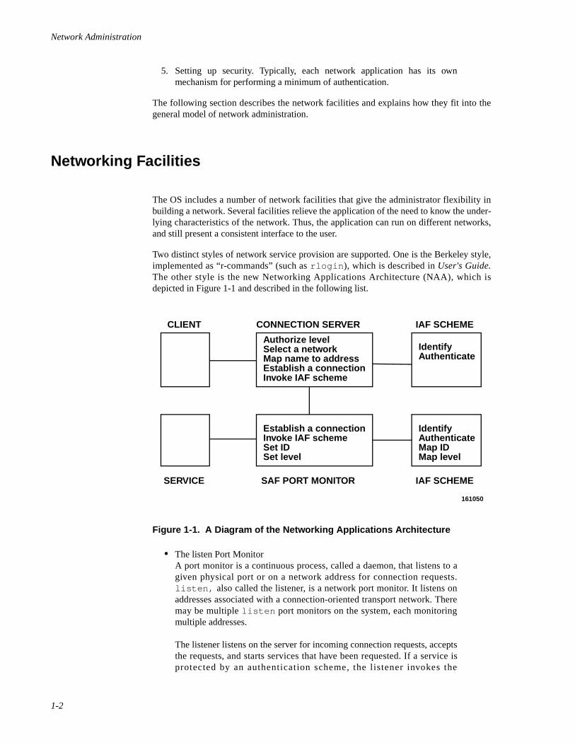
Network Administration
1-2
5. Setting up security. Typically, each network application has its ownmechanism for performing a minimum of authentication.
The following section describes the network facilities and explains how they fit into thegeneral model of network administration.
Networking Facilities 1
The OS includes a number of network facilities that give the administrator flexibility inbuilding a network. Several facilities relieve the application of the need to know the under-lying characteristics of the network. Thus, the application can run on different networks,and still present a consistent interface to the user.
Two distinct styles of network service provision are supported. One is the Berkeley style,implemented as “r-commands” (such as rlogin ), which is described in User's Guide.The other style is the new Networking Applications Architecture (NAA), which isdepicted in Figure 1-1 and described in the following list.
Figure 1-1. A Diagram of the Networking Applications Architecture
• The listen Port Monitor A port monitor is a continuous process, called a daemon, that listens to agiven physical port or on a network address for connection requests.listen, also called the listener, is a network port monitor. It listens onaddresses associated with a connection-oriented transport network. Theremay be multiple listen port monitors on the system, each monitoringmultiple addresses.
The listener listens on the server for incoming connection requests, acceptsthe requests, and starts services that have been requested. If a service isprotected by an authentication scheme, the l istener invokes the
Authorize levelSelect a networkMap name to addressEstablish a connectionInvoke IAF scheme
IdentifyAuthenticate
Establish a connectionInvoke IAF schemeSet IDSet level
IdentifyAuthenticateMap IDMap level
CLIENT
SERVICE
CONNECTION SERVER
SAF PORT MONITOR
IAF SCHEME
IAF SCHEME
161050
Introduction to Network Services Administration
1-3
authentication scheme. If the authentication protocol completes success-fully, the client user's identity is mapped to an identity on the server; then,the port monitor starts the requested service.
All port monitors, including listen, are managed by the Service AccessFacility (SAF). The SAF generalizes service access procedures so loginaccess on the local system and network access to local services aremanaged in similar ways. This means, from the system administrator'sperspective, that local and network access are managed similarly, as isaccess over different networks. (For more information, see the chapter“Managing Ports” in the System Administration guide.)
• The Connection Server The Connection Server can be viewed as a counterpart on the client to theserver's listener. When a client user attempts to access a service fromanother machine on the network, the Connection Server verifies theconnection is allowable at the client's level. The Connection Server usesNetwork Selection to determine which network to use, and Name-to-Address Mapping to determine the address of the requested service on therequested host. The Connection Server sends a connection request to theserver, manages the client's role in establishing the connection, and invokesthe appropriate authentication scheme. If the scheme completessuccessfully, the Connection Server turns over the connection to the clientprocess.
• Identification and Authentication Facility The Identification and Authentication Facility (IAF) authenticates networkconnections independently of the network application. It consists of threecomponents—an invocation function, the cr1 and login authenticationschemes, and the ID Mapping facility. The cr1 schemes (see the chapterentitled “cr1 Bilateral Authentication Scheme), and ID Mapping (see thechapter entitled “Administering ID Mapping), are discussed as separatefeatures.
Following the establishment of a connection, the Connection Server andthe port monitor each invoke an authentication scheme. Once the clientscheme has succeeded, the Connection Server passes the connection to theclient application. Once the server scheme has succeeded, it searches theID Mapping database to determine how the user on the client should bemapped to a user on the server. Minimally, the database consists of a mapfile that maps user logins on client systems to user logins on the server.Once the scheme maps the client user's identity into a local identity, theport monitor invokes the requested service.
Authentication schemes are invoked by the IAF. This release of the OScontains the cr1 authentication scheme. By default, cr1 uses DESencryption, and can also be referenced as cr1.des. Because of exportrestrictions on DES, cr1 can also use ENIGMA encryption. When usingENIGMA encryption, cr1 is referenced as cr1.enigma. Other than theunderlying encryption algorithm used, all cr1 schemes behave identically.The cr1 schemes operate as follows: The client and server schemesexchange a sequence of encrypted messages. Each system uses a secretkey, which it retrieves from its local cr1 key database, to encrypt its ownmessages and decrypt the other's messages. (A secret key is a bit string
Network Administration
1-4
known only to the client and server.) By successfully decrypting the other'smessages, each machine authenticates the other's identity.The clientscheme informs the server scheme of its user's security level and identity.
• Network SelectionNetwork Selection is a facility that generalizes the way an applicationchooses a network. It allows an administrator or a user to specify an orderof preference among available transport providers. When a user attempts toaccess a remote service, the system first attempts to make the connectionover the primary network; if that attempt fails, it tries each network in orderof preference until the connection is made.
• Name-to-Address MappingName-to-Address Mapping is a feature that allows applications to obtaintransport-specific addresses in a transport-independent manner. Theadministrator maintains a configuration file with records describing eachtransport provider available to be used by applications. One of the fields ineach record is the name of the shared library to use for the transportprovider being described in the record. This library contains name-to-address mapping routines specific to the transport protocol. When a newtransport protocol is being installed, a new entry in the configuration file ismade, allowing network applications to make use of the new protocol with-out being changed.
• User-Level ServicesThe facilities that provide services to end-users include the BasicNetworking Utilities (BNU) and REXEC. BNU provides basic networkcommunication (such as queued remote execution and file transfercapabilities) and REXEC is an interactive remote execution facility.Whereas many network packages provide remote execution capabilities,BNU and REXEC provide file transfer and remote execution independentof the transport provider. Both BNU and REXEC take advantage of thefeatures of the Network Application Architecture (NAA) described in theprevious sections.
In addition to BNU and REXEC, the OS includes a distributed file systempackage, the Network File System (NFS). NFS provides access to files anddirectories across a network of machines running different operatingsystems. In addition, TCP/IP includes a number of application level ser-vices in its protocol suite.
BNU and REXEC are described in this chapter. Distributed File Systemsare described in “Introduction to DFS Administration,” “Setting Up DFS,”“Using DFS Commands and Files,” and “DFS sysadm Interface.” The userservices that are provided by TCP/IP are discussed in User's Guide.
The following section leads you step-by-step through administration of BNU and REXEC.
Introduction to Network Services Administration
1-5
Procedural Overview of BNU and REXEC Administration 1
Ultimately, the network administrator's objective is to provide services to users of net-worked machines. This section presents a high-level procedure for setting up REXEC andBNU, as well as all the network services on which they depend. The administration ofeach component mentioned in the following procedure is described in more detail later inthe chapter.
This procedure makes the following assumptions:
1. Your network hardware and software have been installed and anyadministration specific to the network package has been completed.
2. Applications are to be set up to take advantage of the IAF in the OS. Forcompatibility, BNU can be configured as it was on previous versions of theOS. However, this section assumes BNU connections will be configuredusing enhanced authentication procedures (primarily cr1).
Set Up the Network Administrator's Login 1
If you are running the Least Privilege Module (LPM), which is provided as part of theEnhanced Security Utilities, the concept of the superuser is replaced by administrativeroles. Each administrative role is associated with commands and privileges required toadminister a certain aspect of the system. To administer network services, you mustassume the role of the network administrator, NET. NET is predefined on the system; how-ever, before you can log in as a network administrator, you must create a login and assignit the NET role. This is done using the adminuser command. For information aboutassigning roles, see the chapter “Securing User Accounts” in the System Administrationguide or adminuser(1M) .
You must complete this task before beginning the following sequence of steps.
Step 1: Set Up Network Selection 1
Network Selection consists of the following elements:
• netconfig, a network configuration file [see netconfig(4) ]
• NETPATH, an environment variable
To set up Network Selection, you need to create an entry in the netconfig file for eachnetwork available to the local system.
Any user, including the administrator, may use the NETPATH variable to modify thedefault order in which networks are tried by an application seeking a network connection.If a user does not set the NETPATH variable, networks are used in the order specified innetconfig.
For more information see Chapter 2, "Administering Network Selection".
Network Administration
1-6
Step 2: Set Up Name-to-Address Mapping 1
Name-to-Address Mapping consists of routines that application programs can call todetermine the addresses of services and machines on the network. These routines arecombined into libraries, with one library associated with each available transport provider.For every network available to the local system, the network administrator must create andmaintain the following files used by the library routines:
• the hosts file, which lists the addresses of machines on the network
• the services file, which lists the port numbers of services availableacross the network
The files that support TCP/IP must be located in /etc . The files that support other net-works must be located in /etc/net/ transport, where transport is the name of thetransport provider.
For more information, see Chapter 3, “Administering Name-to-Address Mapping.”
Step 3: Set Up the listen Port Monitor 1
The listener is a port monitor under the control of the Service Access Controller (SAC), adaemon process that provides a consistent interface to all services, whether the user'sconnection to the system is local or across a network. (Because the purpose of the SAC isnot limited to managing network access, it is not documented in this chapter. For moreinformation about the SAC and setting up the listener, see the chapter “Managing Ports” inthe System Administration guide.) To set up the listener, do the following:
1. Add a listen port monitor to the Service Access Controller's administra-tive file, using sacadm [see sacadm(1M) ].
2. Set up the port monitor's administrative file, using pmadm [seepmadm(1M)]. Setting up the file involves
• adding one or more services to the listener's administrative file
• enabling the service on a port that the listener is monitoring
• associating an authentication scheme with a service
Step 4: Set Up the Connection Server 1
The Connection Server is a daemon process running on the client that makes networkconnections. Applications obtain network connections by calling library routines thataccess the daemon. An error reporting routine (cs_perror ), an associated service(reportscheme ), and three optional administrative files are available. To set up theConnection Server, do the following:
1. Optionally, on the client, set up the file /etc/iaf/serve.allow. The/etc/iaf/serve.allow file enforces authentication, in the event theservice is not protected by an authentication scheme on the server side.
Introduction to Network Services Administration
1-7
2. Optionally, on the client, set up the file /etc/iaf/serve.alias. The/etc/iaf/serve.alias file maps aliases to service names, making itpossible to register a service under two names with different authenticationschemes associated with each name.
3. Optionally, on the client, set up the authentication file, auth. This file listsnetwork services and their associated authentication schemes.
4. If your system is running Mandatory Access Control (MAC), useattradmin to set up LID authorization. The Connection Server usesattribute mapping to determine if a process at a given security level isauthorized to make a connection request to the specified server.(Information on attribute mapping is provided below under Step 6: SettingUp ID Mapping.
5. Add an entry for reportscheme to the port monitor's administrative fileon each server to which the Connection Server should be able to connect.
For more information about Connection Server administration, see Chapter 4, “Adminis-tering the Connection Server.”
Step 5: Set Up the cr1 Authentication Scheme 1
To set up cr1, do the following:
1. Start the keymaster daemon process [see keymaster(1M) ].
2. Administer individual keys using cryptkey [see cryptkey(1) ].
If you intend to set up REXEC or BNU, you need to add keys shared by a client machineand the server machines. Each client and server pair must share identical keys.
For more information, including detailed procedures, see Chapter 5, “cr1 BilateralAuthentication Scheme.”
Step 6: Setting Up ID Mapping 1
cr1 maps remote user identities to the local system using map files that are administeredunder the ID Mapping facility.
On a server, to set up ID Mapping to support cr1, do the following:
1. Use the idadmin command [see idadmin(1M) ] to install cr1 namemapping.
2. If you are running MAC, set up attribute mapping for the RLID attribute,using the attradmin command. cr1 uses the RLID attribute to map levelaliases from client systems to level aliases on the server.
On the client, to set up attribute mapping, do the following:
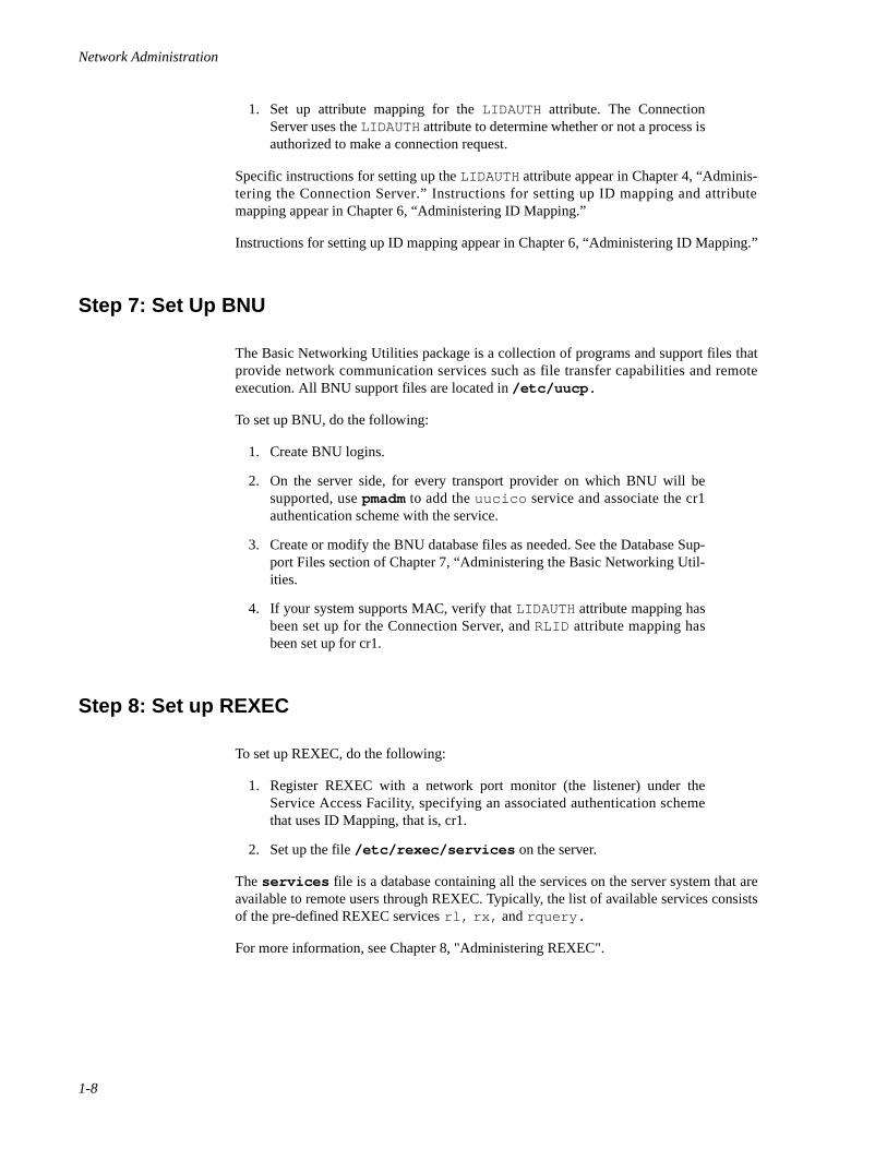
Network Administration
1-8
1. Set up attribute mapping for the LIDAUTH attribute. The ConnectionServer uses the LIDAUTH attribute to determine whether or not a process isauthorized to make a connection request.
Specific instructions for setting up the LIDAUTH attribute appear in Chapter 4, “Adminis-tering the Connection Server.” Instructions for setting up ID mapping and attributemapping appear in Chapter 6, “Administering ID Mapping.”
Instructions for setting up ID mapping appear in Chapter 6, “Administering ID Mapping.”
Step 7: Set Up BNU 1
The Basic Networking Utilities package is a collection of programs and support files thatprovide network communication services such as file transfer capabilities and remoteexecution. All BNU support files are located in /etc/uucp.
To set up BNU, do the following:
1. Create BNU logins.
2. On the server side, for every transport provider on which BNU will besupported, use pmadm to add the uucico service and associate the cr1authentication scheme with the service.
3. Create or modify the BNU database files as needed. See the Database Sup-port Files section of Chapter 7, “Administering the Basic Networking Util-ities.
4. If your system supports MAC, verify that LIDAUTH attribute mapping hasbeen set up for the Connection Server, and RLID attribute mapping hasbeen set up for cr1.
Step 8: Set up REXEC 1
To set up REXEC, do the following:
1. Register REXEC with a network port monitor (the listener) under theService Access Facility, specifying an associated authentication schemethat uses ID Mapping, that is, cr1.
2. Set up the file /etc/rexec/services on the server.
The services file is a database containing all the services on the server system that areavailable to remote users through REXEC. Typically, the list of available services consistsof the pre-defined REXEC services rl, rx, and rquery.
For more information, see Chapter 8, "Administering REXEC".
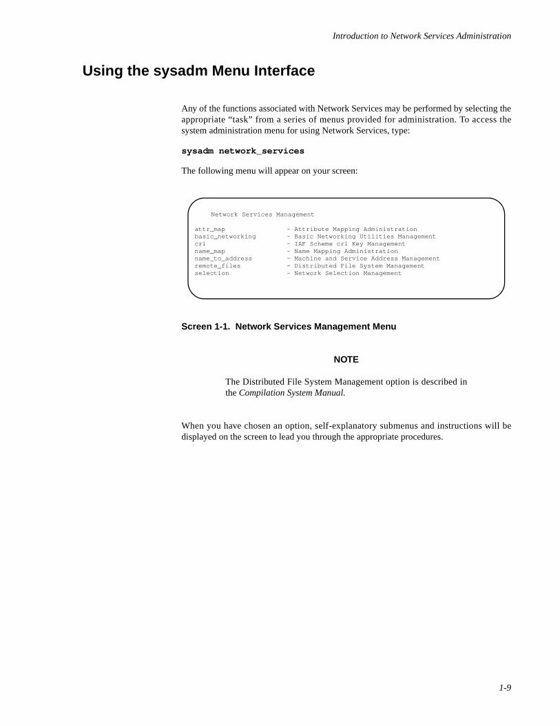
Introduction to Network Services Administration
1-9
Using the sysadm Menu Interface 1
Any of the functions associated with Network Services may be performed by selecting theappropriate “task” from a series of menus provided for administration. To access thesystem administration menu for using Network Services, type:
sysadm network_services
The following menu will appear on your screen:
Screen 1-1. Network Services Management Menu
NOTE
The Distributed File System Management option is described inthe Compilation System Manual.
When you have chosen an option, self-explanatory submenus and instructions will bedisplayed on the screen to lead you through the appropriate procedures.
Network Services Management
attr_map - Attribute Mapping Administrationbasic_networking - Basic Networking Utilities Managementcr1 - IAF Scheme cr1 Key Managementname_map - Name Mapping Administrationname_to_address - Machine and Service Address Managementremote_files - Distributed File System Managementselection - Network Selection Management

Network Administration
1-10
2Administering Network Selection
Introduction to Network Selection Administration . . . . . . . . . . . . . . . . . . . . . . . . . . 2-1Network Selection Overview. . . . . . . . . . . . . . . . . . . . . . . . . . . . . . . . . . . . . . . . . . . 2-2The /etc/netconfig File. . . . . . . . . . . . . . . . . . . . . . . . . . . . . . . . . . . . . . . . . . . . . . . . 2-3The NETPATH Environment Variable. . . . . . . . . . . . . . . . . . . . . . . . . . . . . . . . . . . . 2-6

Network Administration
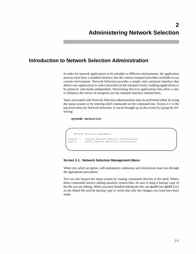
2-1
2Chapter 2Administering Network Selection
222
Introduction to Network Selection Administration 2
In order for network applications to be portable to different environments, the applicationprocess must have a standard interface into the various transport providers available in anycurrent environment. Network Selection provides a simple and consistent interface thatallows user applications to select networks (at the transport level), enabling applications tobe protocol- and media-independent. Networking Services applications that allow a userto influence the choice of transports use the standard interface outlined here.
Tasks associated with Network Selection administration may be performed either by usingthe menu system or by entering shell commands on the command line. Screen 2-1 is thetop-level menu for Network Selection. It can be brought up on the screen by typing the fol-lowing:
sysadm selection
Screen 2-1. Network Selection Management Menu
When you select an option, self-explanatory submenus and instructions lead you throughthe appropriate procedures.
You can also bypass the menu system by issuing commands directly to the shell. Wherethese commands involve editing sensitive system files, be sure to keep a backup copy ofthe file you are editing. When you have finished editing the file, use diff [see diff(1) ]on the edited file and the backup copy to verify that only the changes you want have beenmade.
Network Selection Management
display - Display Network Selection Configurationmodify - Modify Network Selection Configuration
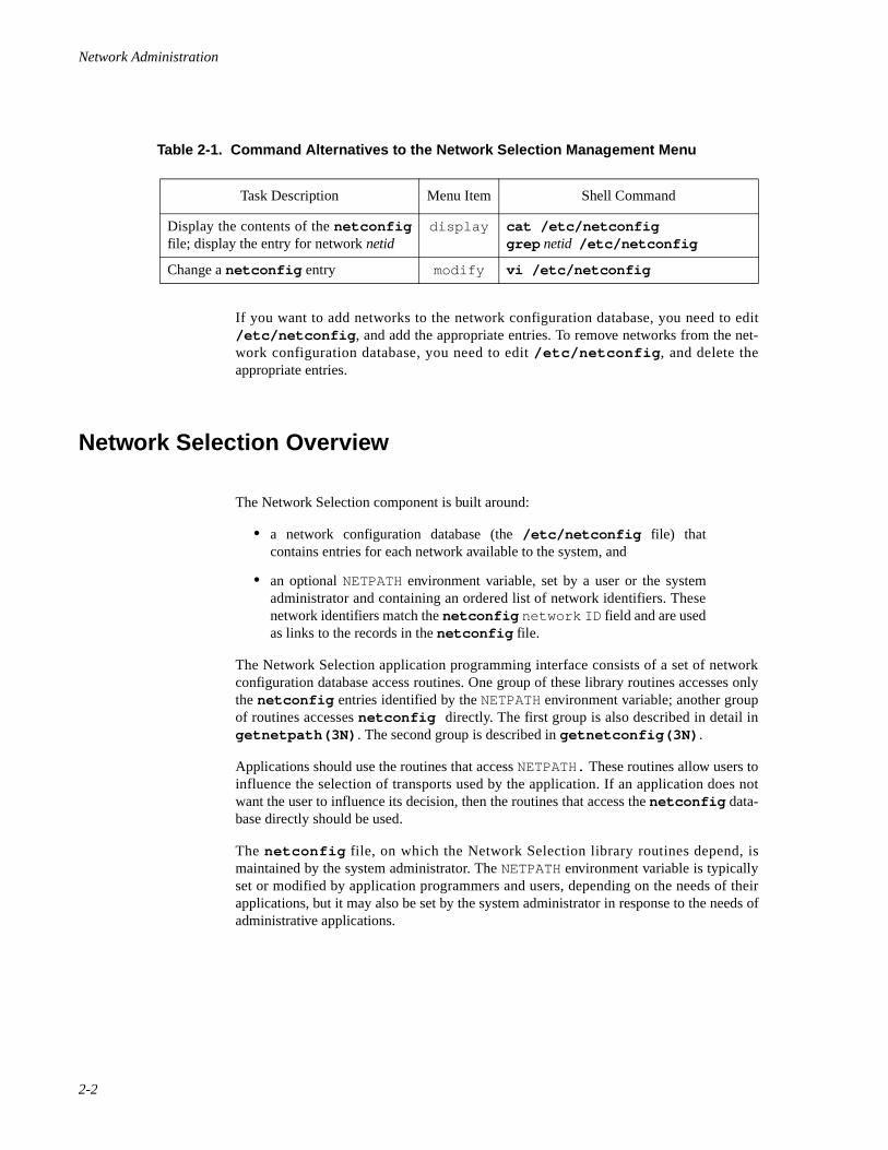
Network Administration
2-2
If you want to add networks to the network configuration database, you need to edit/etc/netconfig , and add the appropriate entries. To remove networks from the net-work configuration database, you need to edit /etc/netconfig , and delete theappropriate entries.
Network Selection Overview 2
The Network Selection component is built around:
• a network configuration database (the /etc/netconfig file) thatcontains entries for each network available to the system, and
• an optional NETPATH environment variable, set by a user or the systemadministrator and containing an ordered list of network identifiers. Thesenetwork identifiers match the netconfig network ID field and are usedas links to the records in the netconfig file.
The Network Selection application programming interface consists of a set of networkconfiguration database access routines. One group of these library routines accesses onlythe netconfig entries identified by the NETPATH environment variable; another groupof routines accesses netconfig directly. The first group is also described in detail ingetnetpath(3N) . The second group is described in getnetconfig(3N) .
Applications should use the routines that access NETPATH. These routines allow users toinfluence the selection of transports used by the application. If an application does notwant the user to influence its decision, then the routines that access the netconfig data-base directly should be used.
The netconfig file, on which the Network Selection library routines depend, ismaintained by the system administrator. The NETPATH environment variable is typicallyset or modified by application programmers and users, depending on the needs of theirapplications, but it may also be set by the system administrator in response to the needs ofadministrative applications.
Table 2-1. Command Alternatives to the Network Selection Management Menu
Task Description Menu Item Shell Command
Display the contents of the netconfigfile; display the entry for network netid
display cat /etc/netconfig grep netid /etc/netconfig
Change a netconfig entry modify vi /etc/netconfig
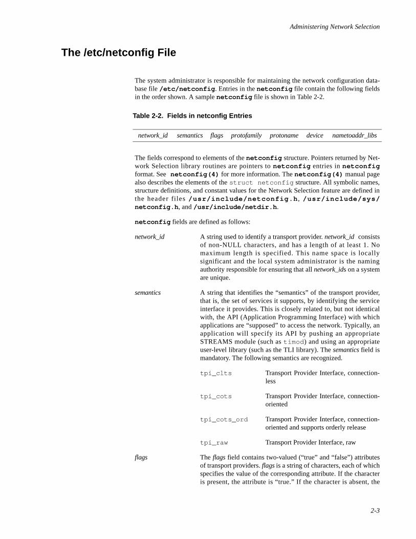
Administering Network Selection
2-3
The /etc/netconfig File 2
The system administrator is responsible for maintaining the network configuration data-base file /etc/netconfig . Entries in the netconfig file contain the following fieldsin the order shown. A sample netconfig file is shown in Table 2-2.
The fields correspond to elements of the netconfig structure. Pointers returned by Net-work Selection library routines are pointers to netconfig entries in netconfigformat. See netconfig(4) for more information. The netconfig(4) manual pagealso describes the elements of the struct netconfig structure. All symbolic names,structure definitions, and constant values for the Network Selection feature are defined inthe header fi les /usr/include/netconfig.h , /usr/include/sys/netconfig.h , and /usr/include/netdir.h .
netconfig fields are defined as follows:
network_id A string used to identify a transport provider. network_id consistsof non-NULL characters, and has a length of at least 1. Nomaximum length is specified. This name space is locallysignificant and the local system administrator is the namingauthority responsible for ensuring that all network_ids on a systemare unique.
semantics A string that identifies the “semantics” of the transport provider,that is, the set of services it supports, by identifying the serviceinterface it provides. This is closely related to, but not identicalwith, the API (Application Programming Interface) with whichapplications are “supposed” to access the network. Typically, anapplication will specify its API by pushing an appropriateSTREAMS module (such as timod ) and using an appropriateuser-level library (such as the TLI library). The semantics field ismandatory. The following semantics are recognized.
tpi_clts Transport Provider Interface, connection-less
tpi_cots Transport Provider Interface, connection-oriented
tpi_cots_ord Transport Provider Interface, connection-oriented and supports orderly release
tpi_raw Transport Provider Interface, raw
flags The flags field contains two-valued (“true” and “false”) attributesof transport providers. flags is a string of characters, each of whichspecifies the value of the corresponding attribute. If the characteris present, the attribute is “true.” If the character is absent, the
Table 2-2. Fields in netconfig Entries
network_id semantics flags protofamily protoname device nametoaddr_libs
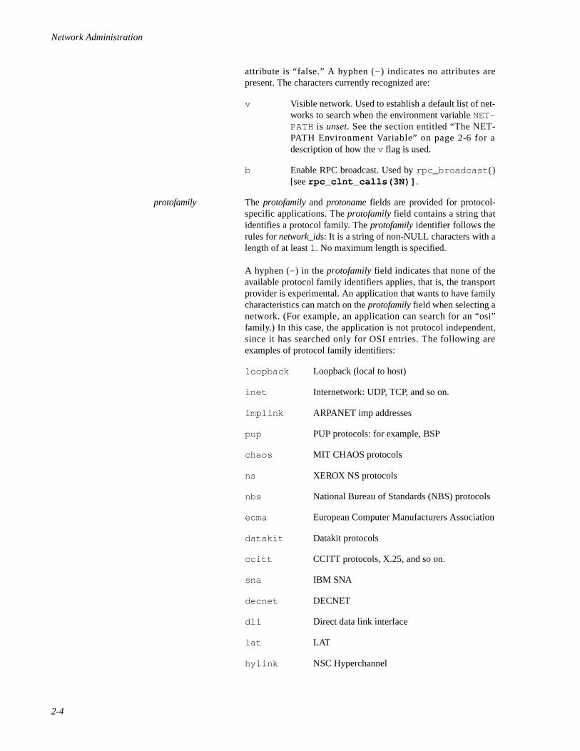
Network Administration
2-4
attribute is “false.” A hyphen (- ) indicates no attributes arepresent. The characters currently recognized are:
v Visible network. Used to establish a default list of net-works to search when the environment variable NET-PATH is unset. See the section entitled “The NET-PATH Environment Variable” on page 2-6 for adescription of how the v flag is used.
b Enable RPC broadcast. Used by rpc_broadcast ()[see rpc_clnt_calls(3N)] .
protofamily The protofamily and protoname fields are provided for protocol-specific applications. The protofamily field contains a string thatidentifies a protocol family. The protofamily identifier follows therules for network_ids: It is a string of non-NULL characters with alength of at least 1. No maximum length is specified.
A hyphen (- ) in the protofamily field indicates that none of theavailable protocol family identifiers applies, that is, the transportprovider is experimental. An application that wants to have familycharacteristics can match on the protofamily field when selecting anetwork. (For example, an application can search for an “osi”family.) In this case, the application is not protocol independent,since it has searched only for OSI entries. The following areexamples of protocol family identifiers:
loopback Loopback (local to host)
inet Internetwork: UDP, TCP, and so on.
implink ARPANET imp addresses
pup PUP protocols: for example, BSP
chaos MIT CHAOS protocols
ns XEROX NS protocols
nbs National Bureau of Standards (NBS) protocols
ecma European Computer Manufacturers Association
datakit Datakit protocols
ccitt CCITT protocols, X.25, and so on.
sna IBM SNA
decnet DECNET
dli Direct data link interface
lat LAT
hylink NSC Hyperchannel
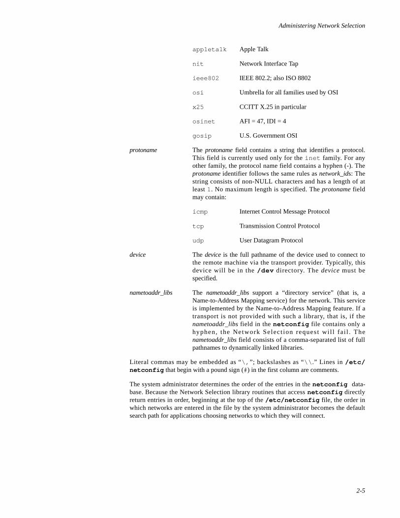
Administering Network Selection
2-5
appletalk Apple Talk
nit Network Interface Tap
ieee802 IEEE 802.2; also ISO 8802
osi Umbrella for all families used by OSI
x25 CCITT X.25 in particular
osinet AFI = 47, IDI = 4
gosip U.S. Government OSI
protoname The protoname field contains a string that identifies a protocol.This field is currently used only for the inet family. For anyother family, the protocol name field contains a hyphen (-). Theprotoname identifier follows the same rules as network_ids: Thestring consists of non-NULL characters and has a length of atleast 1. No maximum length is specified. The protoname fieldmay contain:
icmp Internet Control Message Protocol
tcp Transmission Control Protocol
udp User Datagram Protocol
device The device is the full pathname of the device used to connect tothe remote machine via the transport provider. Typically, thisdevice will be in the /dev directory. The device must bespecified.
nametoaddr_libs The nametoaddr_libs support a “directory service” (that is, aName-to-Address Mapping service) for the network. This serviceis implemented by the Name-to-Address Mapping feature. If atransport is not provided with such a library, that is, if thenametoaddr_libs field in the netconfig file contains only ahyphen, the Network Select ion request wi l l fa i l . Thenametoaddr_libs field consists of a comma-separated list of fullpathnames to dynamically linked libraries.
Literal commas may be embedded as “\, ”; backslashes as “\\ .” Lines in /etc/netconfig that begin with a pound sign (#) in the first column are comments.
The system administrator determines the order of the entries in the netconfig data-base. Because the Network Selection library routines that access netconfig directlyreturn entries in order, beginning at the top of the /etc/netconfig file, the order inwhich networks are entered in the file by the system administrator becomes the defaultsearch path for applications choosing networks to which they will connect.
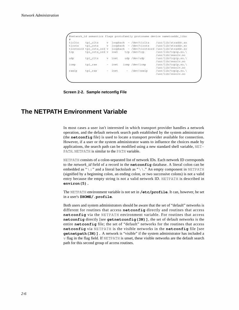
Network Administration
2-6
Screen 2-2. Sample netconfig File
The NETPATH Environment Variable 2
In most cases a user isn't interested in which transport provider handles a networkoperation, and the default network search path established by the system administrator(the netconfig file) is used to locate a transport provider available for connection.However, if a user or the system administrator wants to influence the choices made byapplications, the search path can be modified using a new standard shell variable, NET-PATH. NETPATH is similar to the PATH variable.
NETPATH consists of a colon-separated list of network IDs. Each network ID correspondsto the network_id field of a record in the netconfig database. A literal colon can beembedded as “\: ” and a literal backslash as “\\ .” An empty component in NETPATH(signified by a beginning colon, an ending colon, or two successive colons) is not a validentry because the empty string is not a valid network ID. NETPATH is described inenviron(5).
The NETPATH environment variable is not set in /etc/profile . It can, however, be setin a user's $HOME/.profile .
Both users and system administrators should be aware that the set of “default” networks isdifferent for routines that access netconfig directly and routines that accessnetconfig via the NETPATH environment variable. For routines that accessnetconfig directly [see getnetconfig(3N)] , the set of default networks is theentire netconfig file; the set of “default” networks for the routines that accessnetconfig via NETPATH is the visible networks in the netconfig file [seegetnetpath(3N)]. A network is “visible” if the system administrator has included av flag in the flag field. If NETPATH is unset, these visible networks are the default searchpath for this second group of access routines.
#network_id semantics flags protofamily protoname device nametoaddr_libs#ticlts tpi_clts v loopback - /dev/ticlts /usr/lib/straddr.soticots tpi_cots v loopback - /dev/ticots /usr/lib/straddr.soticotsord tpi_cots_ord v loopback - /dev/ticotsord /usr/lib/straddr.sotcp tpi_cots_ord v inet tcp /dev/tcp /usr/lib/tcpip.so,\ /usr/lib/resolv.soudp tpi_clts v inet udp /dev/udp /usr/lib/tcpip.so,\ /usr/lib/resolv.soicmp tpi_raw - inet icmp /dev/icmp /usr/lib/tcpip.so,\ /usr/lib/resolv.sorawip tpi_raw - inet - /dev/rawip /usr/lib/tcpip.so,\ /usr/lib/resolv.so
3Administering Name-to-Address Mapping
Introduction to Name-to-Address Mapping Administration . . . . . . . . . . . . . . . . . . . 3-1The tcpip.so Library . . . . . . . . . . . . . . . . . . . . . . . . . . . . . . . . . . . . . . . . . . . . . . 3-2The tcip_nis.so Library. . . . . . . . . . . . . . . . . . . . . . . . . . . . . . . . . . . . . . . . . . . . 3-3The resolv.so Library . . . . . . . . . . . . . . . . . . . . . . . . . . . . . . . . . . . . . . . . . . . . . 3-3The straddr.so Library . . . . . . . . . . . . . . . . . . . . . . . . . . . . . . . . . . . . . . . . . . . . 3-3

Network Administration
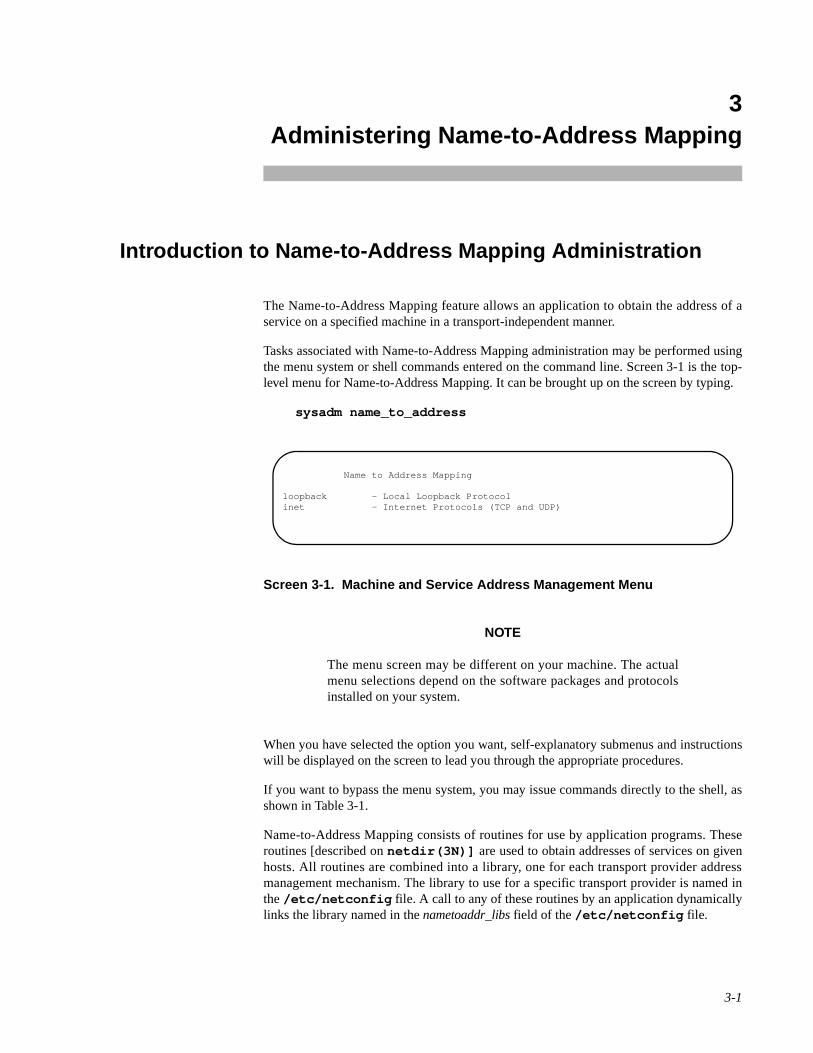
3-1
3Chapter 3Administering Name-to-Address Mapping
333
Introduction to Name-to-Address Mapping Administration 3
The Name-to-Address Mapping feature allows an application to obtain the address of aservice on a specified machine in a transport-independent manner.
Tasks associated with Name-to-Address Mapping administration may be performed usingthe menu system or shell commands entered on the command line. Screen 3-1 is the top-level menu for Name-to-Address Mapping. It can be brought up on the screen by typing.
sysadm name_to_address
Screen 3-1. Machine and Service Address Management Menu
NOTE
The menu screen may be different on your machine. The actualmenu selections depend on the software packages and protocolsinstalled on your system.
When you have selected the option you want, self-explanatory submenus and instructionswill be displayed on the screen to lead you through the appropriate procedures.
If you want to bypass the menu system, you may issue commands directly to the shell, asshown in Table 3-1.
Name-to-Address Mapping consists of routines for use by application programs. Theseroutines [described on netdir(3N)] are used to obtain addresses of services on givenhosts. All routines are combined into a library, one for each transport provider addressmanagement mechanism. The library to use for a specific transport provider is named inthe /etc/netconfig file. A call to any of these routines by an application dynamicallylinks the library named in the nametoaddr_libs field of the /etc/netconfig file.
Name to Address Mapping
loopback - Local Loopback Protocolinet - Internet Protocols (TCP and UDP)
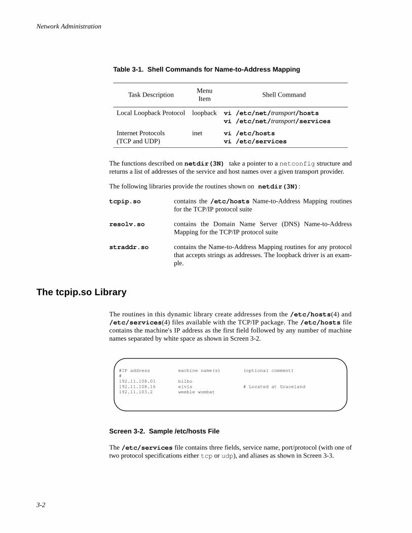
Network Administration
3-2
The functions described on netdir(3N) take a pointer to a netconfig structure andreturns a list of addresses of the service and host names over a given transport provider.
The following libraries provide the routines shown on netdir(3N) :
tcpip.so contains the /etc/hosts Name-to-Address Mapping routinesfor the TCP/IP protocol suite
resolv.so contains the Domain Name Server (DNS) Name-to-AddressMapping for the TCP/IP protocol suite
straddr.so contains the Name-to-Address Mapping routines for any protocolthat accepts strings as addresses. The loopback driver is an exam-ple.
The tcpip.so Library 3
The routines in this dynamic library create addresses from the /etc/hosts (4) and/etc/services (4) files available with the TCP/IP package. The /etc/hosts filecontains the machine's IP address as the first field followed by any number of machinenames separated by white space as shown in Screen 3-2.
Screen 3-2. Sample /etc/hosts File
The /etc/services file contains three fields, service name, port/protocol (with one oftwo protocol specifications either tcp or udp ), and aliases as shown in Screen 3-3.
Table 3-1. Shell Commands for Name-to-Address Mapping
Task DescriptionMenu Item
Shell Command
Local Loopback Protocol loopback vi /etc/net/ transport/hosts vi /etc/net/ transport/services
Internet Protocols (TCP and UDP)
inet vi /etc/hosts vi /etc/services
#IP address machine name(s) (optional comment)#192.11.108.01 bilbo192.11.108.16 elvis # Located at Graceland192.11.103.2 weeble wombat
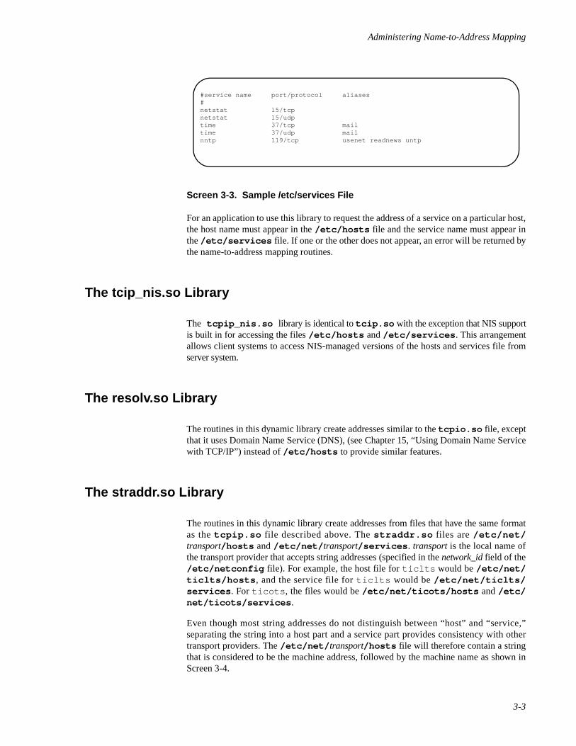
Administering Name-to-Address Mapping
3-3
Screen 3-3. Sample /etc/services File
For an application to use this library to request the address of a service on a particular host,the host name must appear in the /etc/hosts file and the service name must appear inthe /etc/services file. If one or the other does not appear, an error will be returned bythe name-to-address mapping routines.
The tcip_nis.so Library 3
The tcpip_nis.so library is identical to tcip.so with the exception that NIS supportis built in for accessing the files /etc/hosts and /etc/services . This arrangementallows client systems to access NIS-managed versions of the hosts and services file fromserver system.
The resolv.so Library 3
The routines in this dynamic library create addresses similar to the tcpio.so file, exceptthat it uses Domain Name Service (DNS), (see Chapter 15, “Using Domain Name Servicewith TCP/IP”) instead of /etc/hosts to provide similar features.
The straddr.so Library 3
The routines in this dynamic library create addresses from files that have the same formatas the tcpip.so file described above. The straddr.so files are /etc/net/transport/hosts and /etc/net/ transport/services . transport is the local name ofthe transport provider that accepts string addresses (specified in the network_id field of the/etc/netconfig file). For example, the host file for ticlts would be /etc/net/ticlts/hosts , and the service file for ticlts would be /etc/net/ticlts/services . For ticots , the files would be /etc/net/ticots/hosts and /etc/net/ticots/services .
Even though most string addresses do not distinguish between “host” and “service,”separating the string into a host part and a service part provides consistency with othertransport providers. The /etc/net/ transport/hosts file will therefore contain a stringthat is considered to be the machine address, followed by the machine name as shown inScreen 3-4.
#service name port/protocol aliases#netstat 15/tcpnetstat 15/udptime 37/tcp mailtime 37/udp mailnntp 119/tcp usenet readnews untp
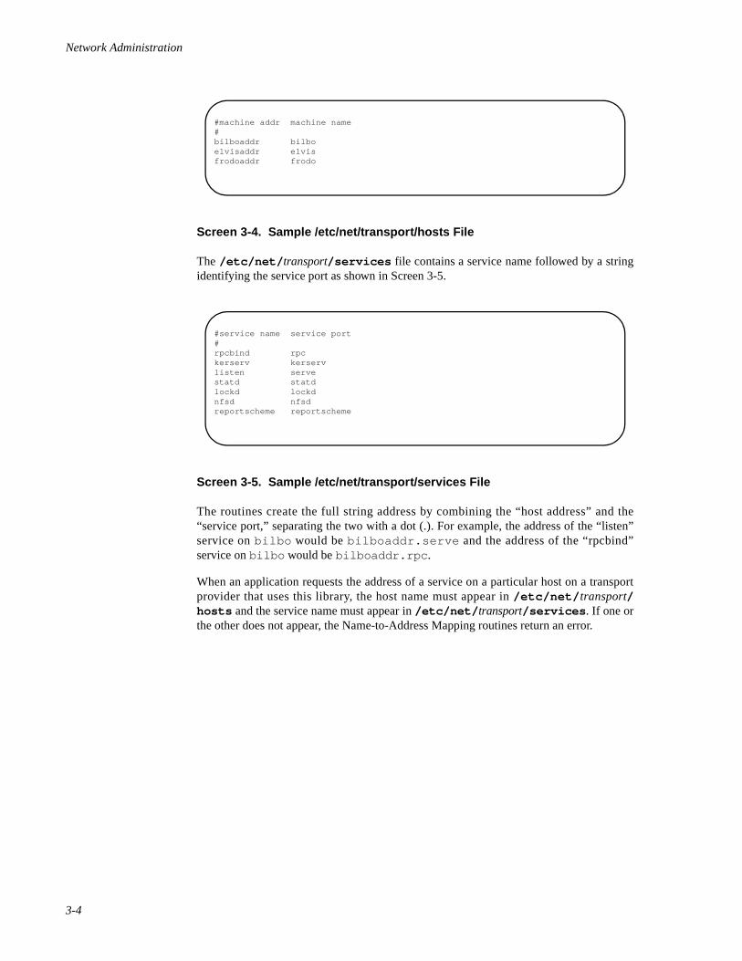
Network Administration
3-4
Screen 3-4. Sample /etc/net/transport/hosts File
The /etc/net/ transport/services file contains a service name followed by a stringidentifying the service port as shown in Screen 3-5.
Screen 3-5. Sample /etc/net/transport/services File
The routines create the full string address by combining the “host address” and the“service port,” separating the two with a dot (.). For example, the address of the “listen”service on bilbo would be bilboaddr.serve and the address of the “rpcbind”service on bilbo would be bilboaddr.rpc .
When an application requests the address of a service on a particular host on a transportprovider that uses this library, the host name must appear in /etc/net/ transport/hosts and the service name must appear in /etc/net/ transport/services . If one orthe other does not appear, the Name-to-Address Mapping routines return an error.
#machine addr machine name#bilboaddr bilboelvisaddr elvisfrodoaddr frodo
#service name service port#rpcbind rpckerserv kerservlisten servestatd statdlockd lockdnfsd nfsdreportscheme reportscheme
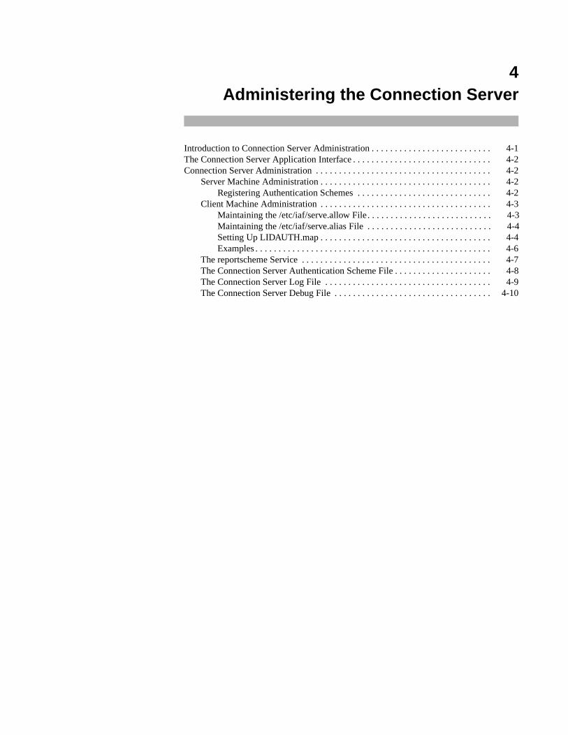
4Administering the Connection Server
Introduction to Connection Server Administration . . . . . . . . . . . . . . . . . . . . . . . . . . 4-1The Connection Server Application Interface . . . . . . . . . . . . . . . . . . . . . . . . . . . . . . 4-2Connection Server Administration . . . . . . . . . . . . . . . . . . . . . . . . . . . . . . . . . . . . . . 4-2
Server Machine Administration . . . . . . . . . . . . . . . . . . . . . . . . . . . . . . . . . . . . . 4-2Registering Authentication Schemes . . . . . . . . . . . . . . . . . . . . . . . . . . . . . 4-2
Client Machine Administration . . . . . . . . . . . . . . . . . . . . . . . . . . . . . . . . . . . . . 4-3Maintaining the /etc/iaf/serve.allow File. . . . . . . . . . . . . . . . . . . . . . . . . . . 4-3Maintaining the /etc/iaf/serve.alias File . . . . . . . . . . . . . . . . . . . . . . . . . . . 4-4Setting Up LIDAUTH.map . . . . . . . . . . . . . . . . . . . . . . . . . . . . . . . . . . . . . 4-4Examples . . . . . . . . . . . . . . . . . . . . . . . . . . . . . . . . . . . . . . . . . . . . . . . . . . . 4-6
The reportscheme Service . . . . . . . . . . . . . . . . . . . . . . . . . . . . . . . . . . . . . . . . . 4-7The Connection Server Authentication Scheme File . . . . . . . . . . . . . . . . . . . . . 4-8The Connection Server Log File . . . . . . . . . . . . . . . . . . . . . . . . . . . . . . . . . . . . 4-9The Connection Server Debug File . . . . . . . . . . . . . . . . . . . . . . . . . . . . . . . . . . 4-10

Network Administration
4-1
4Chapter 4Administering the Connection Server
444
Introduction to Connection Server Administration 4
The Connection Server [see cs(1M) ] is a standing process or daemon that runs on allclient machines. It is used to establish connections for all network services thatcommunicate over TLI connection-oriented and dialup connections. The ConnectionServer is started automatically (from /etc/dinit.d/S80cs ) during initializationwhen the system goes to multi-user state. It receives requests for network services fromclient machine applications, establishes connections to the server-machine portsassociated with the requested services, and passes the connections back to the application.Before passing a connection to an application, the Connection Server may invoke anauthentication scheme.
The Connection Server is made up of the following components:
• An application interface to the standing server. The interface consists oflibrary routines that make the connection over connection-oriented net-works or using dialup connections, and an error reporting routine. The useof the application interface routines is described in The Connection ServerApplication Interface section in this chapter and on cs_connect(3N)and dial(3N) .
• An /etc/iaf/serve.allow file, maintained on the client machine./etc/iaf/serve.allow contains a list of network services that clientapplications expect to use and the acceptable authentication scheme orschemes for each service. This file is not needed if client applications donot authenticate server identities, that is, if client applications will acceptany authentication scheme imposed by server machines. /etc/iaf/serve.allow is described below.
• An optional file, /etc/iaf/serve.alias , also maintained on theclient machine. /etc/iaf/serve.alias contains a list of servernames, network service names and their aliases. The file is describedbelow.
• If the Enhanced Security Utilities are installed, an /etc/idmap/attrmap/LIDAUTH.map file, maintained on the client machine.LIDAUTH.map indicates whether or not the client is authorized to connectto the remote system at the current security level. If LIDAUTH.mapcontains a line that authorizes a connection, the Connection Server sendsthe request to the server. If LIDAUTH.map does not authorize a connectionat the security level of the local process, the Connection Server does notpass the connection request to the server. If a system is running theEnhanced Security Utilities and a LIDAUTH.map file does not exist, the
Network Administration
4-2
Connection Server fails all outgoing connection requests. LIDAUTH.mapis described below.
• A non-standing network service, reportscheme , that tells clientmachine applications what authentication scheme to use for a requestednetwork service. The reportscheme service must exist on each portmonitor that offers network services if the server is to enforceauthentication scheme invocation. reportscheme is described through-out this section and on reportscheme(1M) .
• A Connection Server log file.
In addition, the Connection Server may make use of the Service Access Facility'sadministrative command, pmadm [see pmadm(1M) ], to install authentication schemes.
The Connection Server Application Interface 4
The application interface to the Connection Server consists of the library routinescs_connect () , cs_perror() , and dia l( ) . They a re descr ibed oncs_connect(3N) and dial(3N).
Connection Server Administration 4
An authentication scheme is a program called by listen on the server machine and bythe Connection Server on the client machine. It is called after physical connection takesplace and before the connection is handed over to the service. An authentication programallows client and server machines to verify each other's identities.
Authentication scheme administration is performed on both client and server machines.
Server Machine Administration 4
Registering Authentication Schemes 4
The authentication scheme for a network service is registered using the port monitoradministrative command, pmadm [see pmadm(1M)]. Each network service under theService Access Facility is associated with a port under a given port monitor. The portmonitor administrative command adds, removes, and maintains services by adding,removing, or changing lines in a port monitor's administrative file. (See the chapter“Managing Ports” in the System Administration guide and pmadm(1M) for moreinformation.)
The system administrator must “register” the authentication scheme for a service. If theservice exists on the system, this is done using the port monitor administrative command,pmadm, with the -c and -S scheme options. If an authentication scheme has not already
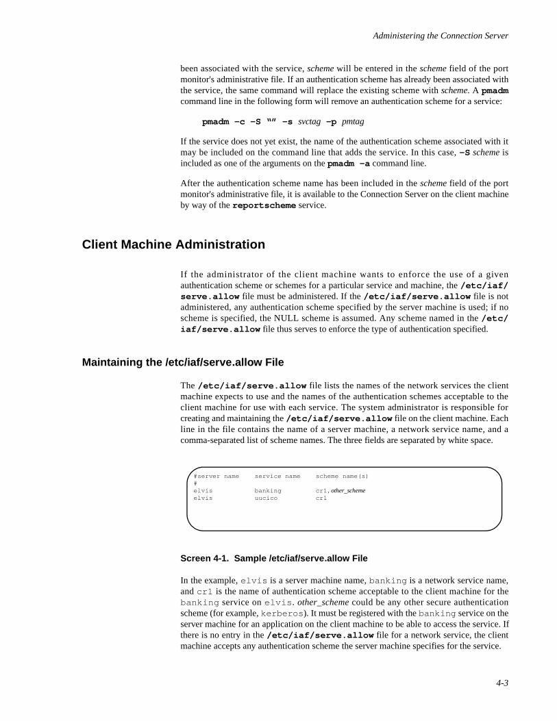
Administering the Connection Server
4-3
been associated with the service, scheme will be entered in the scheme field of the portmonitor's administrative file. If an authentication scheme has already been associated withthe service, the same command will replace the existing scheme with scheme. A pmadmcommand line in the following form will remove an authentication scheme for a service:
pmadm -c -S “” -s svctag -p pmtag
If the service does not yet exist, the name of the authentication scheme associated with itmay be included on the command line that adds the service. In this case, -S scheme isincluded as one of the arguments on the pmadm -a command line.
After the authentication scheme name has been included in the scheme field of the portmonitor's administrative file, it is available to the Connection Server on the client machineby way of the reportscheme service.
Client Machine Administration 4
If the administrator of the client machine wants to enforce the use of a givenauthentication scheme or schemes for a particular service and machine, the /etc/iaf/serve.allow file must be administered. If the /etc/iaf/serve.allow file is notadministered, any authentication scheme specified by the server machine is used; if noscheme is specified, the NULL scheme is assumed. Any scheme named in the /etc/iaf/serve.allow file thus serves to enforce the type of authentication specified.
Maintaining the /etc/iaf/serve.allow File 4
The /etc/iaf/serve.allow file lists the names of the network services the clientmachine expects to use and the names of the authentication schemes acceptable to theclient machine for use with each service. The system administrator is responsible forcreating and maintaining the /etc/iaf/serve.allow file on the client machine. Eachline in the file contains the name of a server machine, a network service name, and acomma-separated list of scheme names. The three fields are separated by white space.
Screen 4-1. Sample /etc/iaf/serve.allow File
In the example, elvis is a server machine name, banking is a network service name,and cr1 is the name of authentication scheme acceptable to the client machine for thebanking service on elvis . other_scheme could be any other secure authenticationscheme (for example, kerberos ). It must be registered with the banking service on theserver machine for an application on the client machine to be able to access the service. Ifthere is no entry in the /etc/iaf/serve.allow file for a network service, the clientmachine accepts any authentication scheme the server machine specifies for the service.
#server name service name scheme name(s)#elvis banking cr1, other_schemeelvis uucico cr1
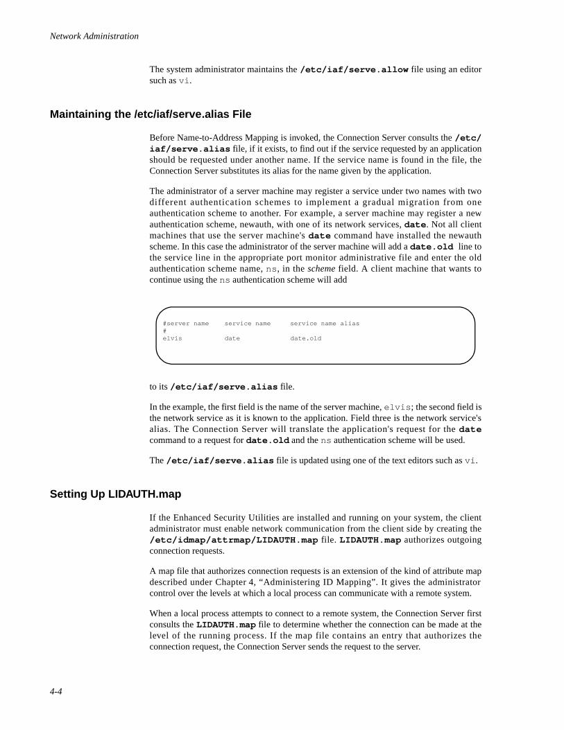
Network Administration
4-4
The system administrator maintains the /etc/iaf/serve.allow file using an editorsuch as vi .
Maintaining the /etc/iaf/serve.alias File 4
Before Name-to-Address Mapping is invoked, the Connection Server consults the /etc/iaf/serve.alias file, if it exists, to find out if the service requested by an applicationshould be requested under another name. If the service name is found in the file, theConnection Server substitutes its alias for the name given by the application.
The administrator of a server machine may register a service under two names with twodifferent authentication schemes to implement a gradual migration from oneauthentication scheme to another. For example, a server machine may register a newauthentication scheme, newauth, with one of its network services, date . Not all clientmachines that use the server machine's date command have installed the newauthscheme. In this case the administrator of the server machine will add a date.old line tothe service line in the appropriate port monitor administrative file and enter the oldauthentication scheme name, ns , in the scheme field. A client machine that wants tocontinue using the ns authentication scheme will add
to its /etc/iaf/serve.alias file.
In the example, the first field is the name of the server machine, elvis ; the second field isthe network service as it is known to the application. Field three is the network service'salias. The Connection Server will translate the application's request for the datecommand to a request for date.old and the ns authentication scheme will be used.
The /etc/iaf/serve.alias file is updated using one of the text editors such as vi .
Setting Up LIDAUTH.map 4
If the Enhanced Security Utilities are installed and running on your system, the clientadministrator must enable network communication from the client side by creating the/etc/idmap/attrmap/LIDAUTH.map file. LIDAUTH.map authorizes outgoingconnection requests.
A map file that authorizes connection requests is an extension of the kind of attribute mapdescribed under Chapter 4, “Administering ID Mapping”. It gives the administratorcontrol over the levels at which a local process can communicate with a remote system.
When a local process attempts to connect to a remote system, the Connection Server firstconsults the LIDAUTH.map file to determine whether the connection can be made at thelevel of the running process. If the map file contains an entry that authorizes theconnection request, the Connection Server sends the request to the server.
#server name service name service name alias#elvis date date.old
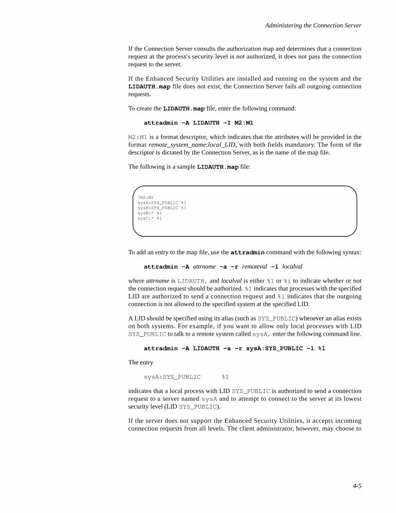
Administering the Connection Server
4-5
If the Connection Server consults the authorization map and determines that a connectionrequest at the process's security level is not authorized, it does not pass the connectionrequest to the server.
If the Enhanced Security Utilities are installed and running on the system and theLIDAUTH.map file does not exist, the Connection Server fails all outgoing connectionrequests.
To create the LIDAUTH.map file, enter the following command:
attradmin -A LIDAUTH -I M2:M1
M2:M1 is a format descriptor, which indicates that the attributes will be provided in theformat remote_system_name:local_LID, with both fields mandatory. The form of thedescriptor is dictated by the Connection Server, as is the name of the map file.
The following is a sample LIDAUTH.map file:
To add an entry to the map file, use the attradmin command with the following syntax:
attradmin -A attrname -a -r remoteval -l localval
where attrname is LIDAUTH, and localval is either %1 or %i to indicate whether or notthe connection request should be authorized. %1 indicates that processes with the specifiedLID are authorized to send a connection request and %i indicates that the outgoingconnection is not allowed to the specified system at the specified LID.
A LID should be specified using its alias (such as SYS_PUBLIC) whenever an alias existson both systems. For example, if you want to allow only local processes with LIDSYS_PUBLIC to talk to a remote system called sysA, enter the following command line.
attradmin -A LIDAUTH -a -r sysA:SYS_PUBLIC -l %1
The entry
sysA:SYS_PUBLIC %1
indicates that a local process with LID SYS_PUBLIC is authorized to send a connectionrequest to a server named sysA and to attempt to connect to the server at its lowestsecurity level (LID SYS_PUBLIC).
If the server does not support the Enhanced Security Utilities, it accepts incomingconnection requests from all levels. The client administrator, however, may choose to
!M2:M1sysA:SYS_PUBLIC %1sysB:SYS_PUBLIC %1sysB:* %isysC:* %1
Network Administration
4-6
restrict access to the server from the client side by including appropriate entries inLIDAUTH.map. The map entries
sysB:SYS_PUBLIC %1sysB:* %i
indicate that the client administrator has chosen to allow only processes at the lowestsecurity level (LID SYS_PUBLIC) to connect to a server named sysB. The second entryin this example is needed only if the LIDAUTH.map file also has an entry
*:* %1
which specifies transparent mapping for all other attribute pairs. If this entry is not in thefile, lack of a match would cause the request to fail and the second entry above would notbe required.
Examples 4
If you know the remote system sysC supports the same security levels and LIDs as thelocal system, and you want to allow communication at all levels, enter the followingcommand line:
attradmin -A LIDAUTH -a -r “sysC:*” -l %1
NOTE
To protect characters that have special meaning to the shell,enclose them in double quotes.
If all the machines on the network support the same levels and LIDS, and you want yourmachine to have access to all network machines at all levels, enter the following:
attradmin -A LIDAUTH -a -r “*:*” -l %1
Remember that a server can still deny the connection request, but the request will fail onthe server, not on the client.
In the following example, transparent mapping is allowed to sysD at all security levels onthe system, with the exception of the LID SYS_PRIVATE. To authorize all connectionrequests with the exception of those with LID SYS_PRIVATE, add the following pair ofentries to LIDAUTH.map:
sysD:SYS_PRIVATE %isysD:* %1
To add the entries, first enter
attradmin -A LIDAUTH -a -r sysD:SYS_PRIVATE -l %i
Then enter
attradmin -A LIDAUTH -a -r “sysD:*” -l %1
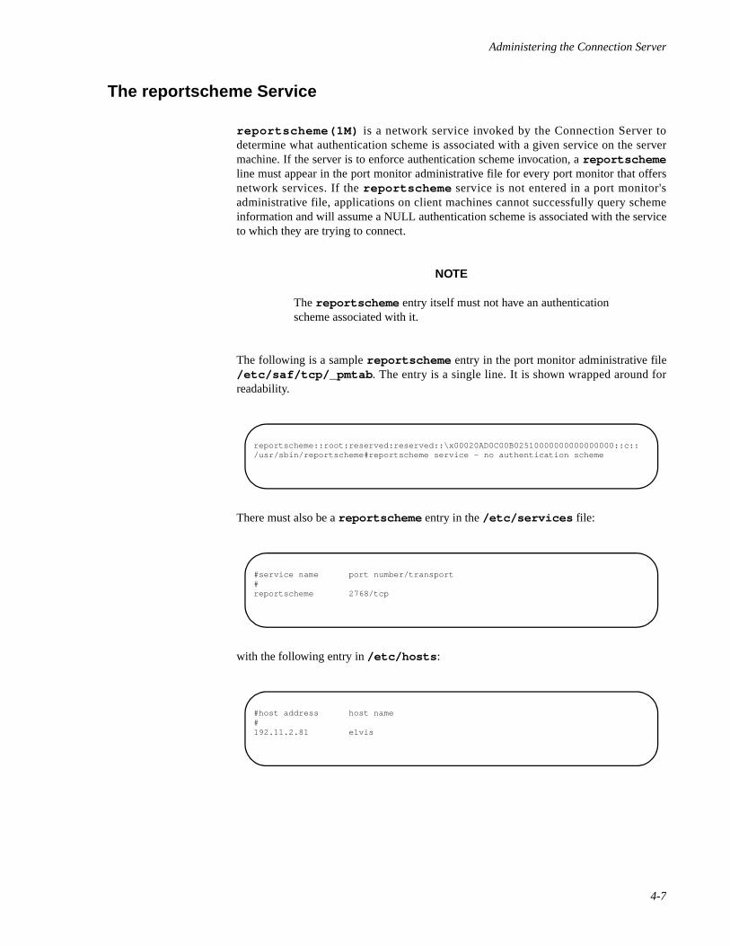
Administering the Connection Server
4-7
The reportscheme Service 4
reportscheme(1M) is a network service invoked by the Connection Server todetermine what authentication scheme is associated with a given service on the servermachine. If the server is to enforce authentication scheme invocation, a reportschemeline must appear in the port monitor administrative file for every port monitor that offersnetwork services. If the reportscheme service is not entered in a port monitor'sadministrative file, applications on client machines cannot successfully query schemeinformation and will assume a NULL authentication scheme is associated with the serviceto which they are trying to connect.
NOTE
The reportscheme entry itself must not have an authenticationscheme associated with it.
The following is a sample reportscheme entry in the port monitor administrative file/etc/saf/tcp/_pmtab . The entry is a single line. It is shown wrapped around forreadability.
There must also be a reportscheme entry in the /etc/services file:
with the following entry in /etc/hosts :
reportscheme::root:reserved:reserved::\x00020AD0C00B02510000000000000000::c::/usr/sbin/reportscheme#reportscheme service - no authentication scheme
#service name port number/transport#reportscheme 2768/tcp
#host address host name#192.11.2.81 elvis
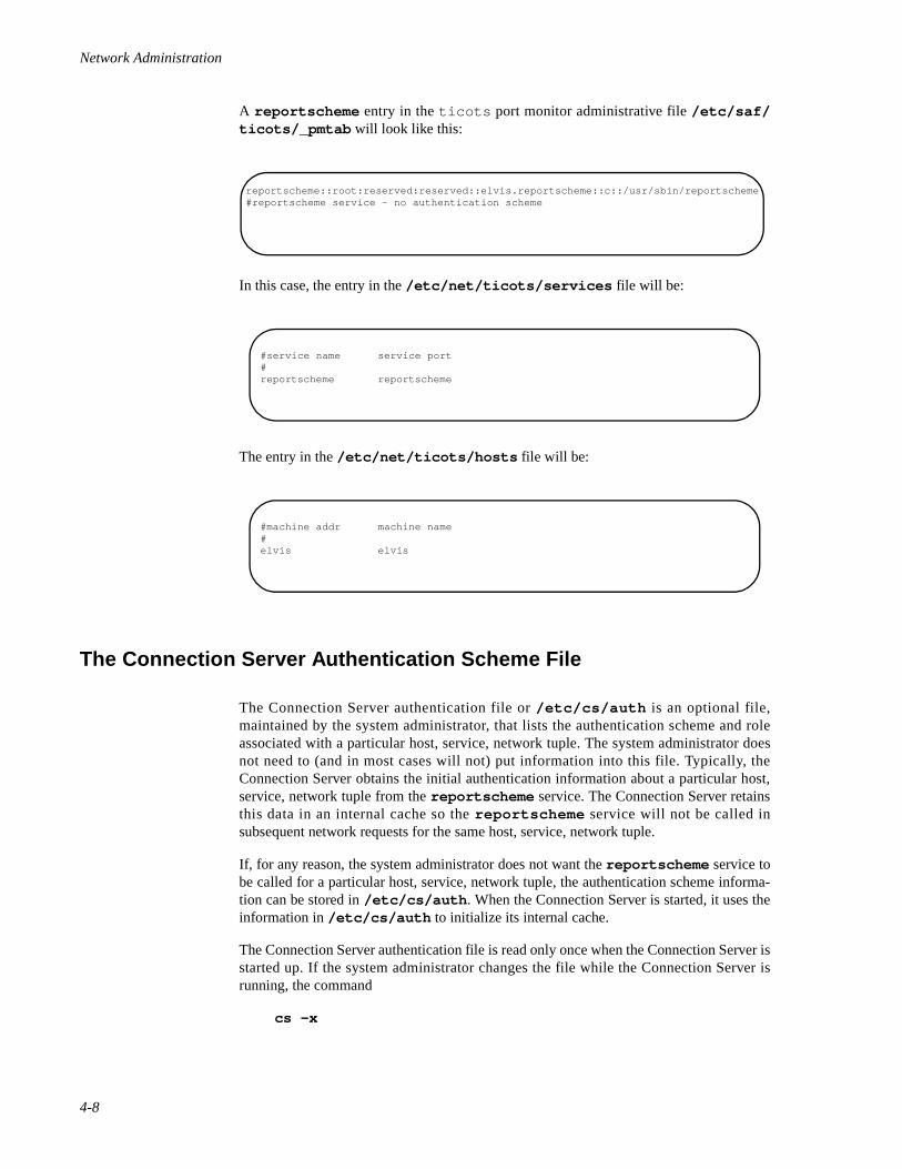
Network Administration
4-8
A reportscheme entry in the ticots port monitor administrative file /etc/saf/ticots/_pmtab will look like this:
In this case, the entry in the /etc/net/ticots/services file will be:
The entry in the /etc/net/ticots/hosts file will be:
The Connection Server Authentication Scheme File 4
The Connection Server authentication file or /etc/cs/auth is an optional file,maintained by the system administrator, that lists the authentication scheme and roleassociated with a particular host, service, network tuple. The system administrator doesnot need to (and in most cases will not) put information into this file. Typically, theConnection Server obtains the initial authentication information about a particular host,service, network tuple from the reportscheme service. The Connection Server retainsthis data in an internal cache so the reportscheme service will not be called insubsequent network requests for the same host, service, network tuple.
If, for any reason, the system administrator does not want the reportscheme service tobe called for a particular host, service, network tuple, the authentication scheme informa-tion can be stored in /etc/cs/auth . When the Connection Server is started, it uses theinformation in /etc/cs/auth to initialize its internal cache.
The Connection Server authentication file is read only once when the Connection Server isstarted up. If the system administrator changes the file while the Connection Server isrunning, the command
cs -x
reportscheme::root:reserved:reserved::elvis.reportscheme::c::/usr/sbin/reportscheme#reportscheme service - no authentication scheme
#service name service port#reportscheme reportscheme
#machine addr machine name#elvis elvis
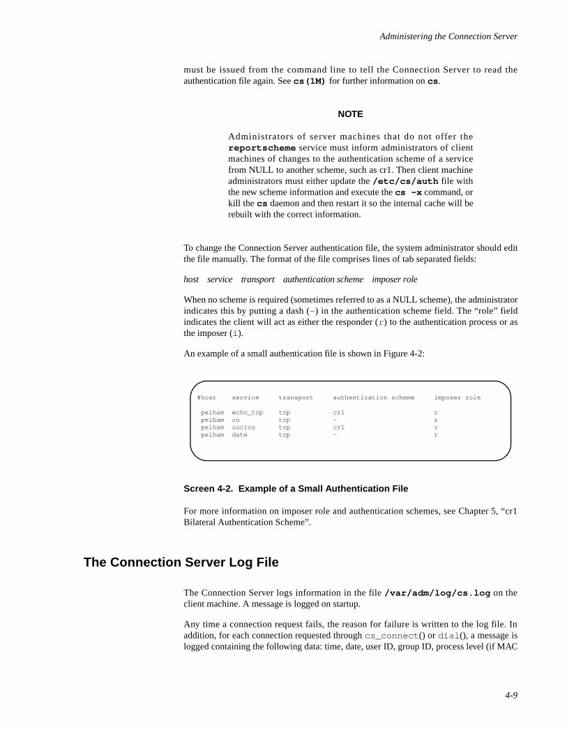
Administering the Connection Server
4-9
must be issued from the command line to tell the Connection Server to read theauthentication file again. See cs(1M) for further information on cs .
NOTE
Administrators of server machines that do not offer thereportscheme service must inform administrators of clientmachines of changes to the authentication scheme of a servicefrom NULL to another scheme, such as cr1. Then client machineadministrators must either update the /etc/cs/auth file withthe new scheme information and execute the cs -x command, orkill the cs daemon and then restart it so the internal cache will berebuilt with the correct information.
To change the Connection Server authentication file, the system administrator should editthe file manually. The format of the file comprises lines of tab separated fields:
host service transport authentication scheme imposer role
When no scheme is required (sometimes referred to as a NULL scheme), the administratorindicates this by putting a dash (- ) in the authentication scheme field. The “role” fieldindicates the client will act as either the responder (r ) to the authentication process or asthe imposer (i ).
An example of a small authentication file is shown in Figure 4-2:
Screen 4-2. Example of a Small Authentication File
For more information on imposer role and authentication schemes, see Chapter 5, “cr1Bilateral Authentication Scheme”.
The Connection Server Log File 4
The Connection Server logs information in the file /var/adm/log/cs.log on theclient machine. A message is logged on startup.
Any time a connection request fails, the reason for failure is written to the log file. Inaddition, for each connection requested through cs_connect () or dial (), a message islogged containing the following data: time, date, user ID, group ID, process level (if MAC
#host service transport authentication scheme imposer role
pelham echo_tcp tcp cr1 r pelham cu tcp - r pelham uucico tcp cr1 r pelham date tcp - r
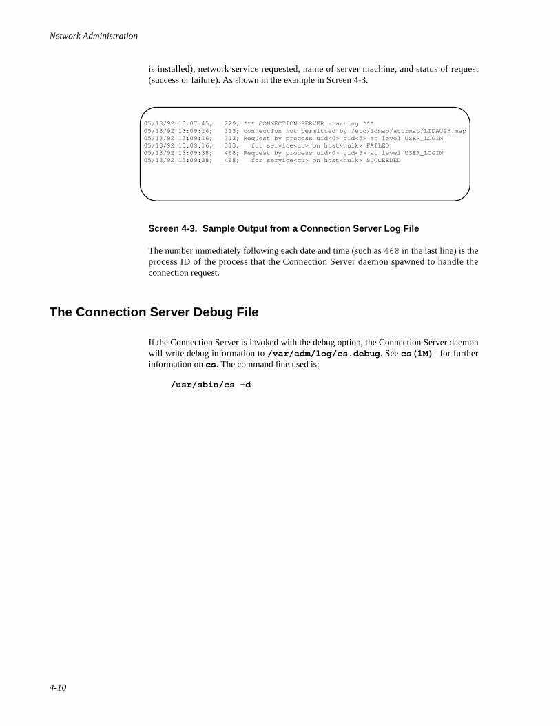
Network Administration
4-10
is installed), network service requested, name of server machine, and status of request(success or failure). As shown in the example in Screen 4-3.
Screen 4-3. Sample Output from a Connection Server Log File
The number immediately following each date and time (such as 468 in the last line) is theprocess ID of the process that the Connection Server daemon spawned to handle theconnection request.
The Connection Server Debug File 4
If the Connection Server is invoked with the debug option, the Connection Server daemonwill write debug information to /var/adm/log/cs.debug . See cs(1M) for furtherinformation on cs . The command line used is:
/usr/sbin/cs -d
05/13/92 13:07:45; 229; *** CONNECTION SERVER starting ***05/13/92 13:09:16; 313; connection not permitted by /etc/idmap/attrmap/LIDAUTH.map05/13/92 13:09:16; 313; Request by process uid<0> gid<5> at level USER_LOGIN05/13/92 13:09:16; 313; for service<cu> on host<hulk> FAILED05/13/92 13:09:38; 468; Request by process uid<0> gid<5> at level USER_LOGIN05/13/92 13:09:38; 468; for service<cu> on host<hulk> SUCCEEDED
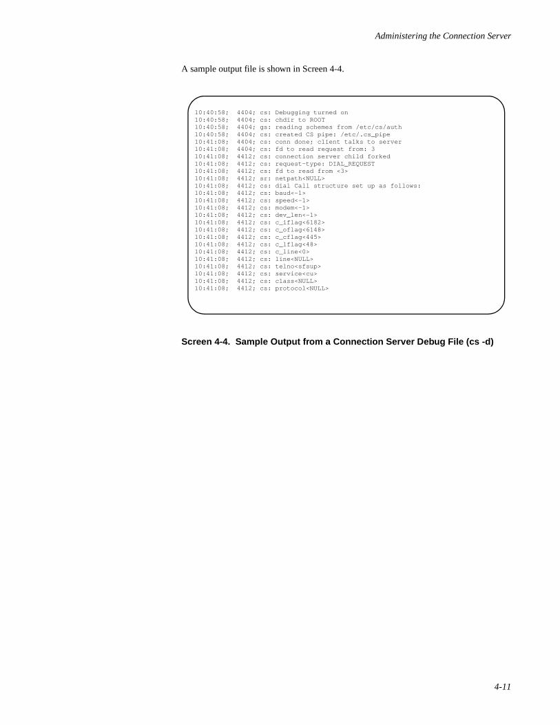
Administering the Connection Server
4-11
A sample output file is shown in Screen 4-4.
Screen 4-4. Sample Output from a Connection Server Debug File (cs -d)
10:40:58; 4404; cs: Debugging turned on10:40:58; 4404; cs: chdir to ROOT10:40:58; 4404; gs: reading schemes from /etc/cs/auth10:40:58; 4404; cs: created CS pipe: /etc/.cs_pipe10:41:08; 4404; cs: conn done; client talks to server10:41:08; 4404; cs: fd to read request from: 310:41:08; 4412; cs: connection server child forked10:41:08; 4412; cs: request-type: DIAL_REQUEST10:41:08; 4412; cs: fd to read from <3>10:41:08; 4412; sr: netpath<NULL>10:41:08; 4412; cs: dial Call structure set up as follows:10:41:08; 4412; cs: baud<-1>10:41:08; 4412; cs: speed<-1>10:41:08; 4412; cs: modem<-1>10:41:08; 4412; cs: dev_len<-1>10:41:08; 4412; cs: c_iflag<6182>10:41:08; 4412; cs: c_oflag<6148>10:41:08; 4412; cs: c_cflag<445>10:41:08; 4412; cs: c_lflag<48>10:41:08; 4412; cs: c_line<0>10:41:08; 4412; cs: line<NULL>10:41:08; 4412; cs: telno<sfsup>10:41:08; 4412; cs: service<cu>10:41:08; 4412; cs: class<NULL>10:41:08; 4412; cs: protocol<NULL>

Network Administration
4-12
5cr1 Bilateral Authentication Scheme
Introduction to the cr1 Bilateral Authentication Scheme . . . . . . . . . . . . . . . . . . . . . 5-1An Overview of cr1 Administration . . . . . . . . . . . . . . . . . . . . . . . . . . . . . . . . . . . . . 5-3Registering cr1 with a Port Monitor . . . . . . . . . . . . . . . . . . . . . . . . . . . . . . . . . . . . . 5-6Registering cr1 with the Connection Server . . . . . . . . . . . . . . . . . . . . . . . . . . . . . . . 5-6Managing the Daemon and the Master Key . . . . . . . . . . . . . . . . . . . . . . . . . . . . . . . 5-7
Starting and Stopping the Daemon. . . . . . . . . . . . . . . . . . . . . . . . . . . . . . . . . . . 5-7Creating a Master Key . . . . . . . . . . . . . . . . . . . . . . . . . . . . . . . . . . . . . . . . . . . . 5-8
Setting Up the Key Database . . . . . . . . . . . . . . . . . . . . . . . . . . . . . . . . . . . . . . . . . . . 5-8

Network Administration
5-1
5Chapter 5cr1 Bilateral Authentication Scheme
555
Introduction to the cr1 Bilateral Authentication Scheme 5
cr1 is an identification and authentication scheme that protects a system fromunauthorized access. By default, cr1 uses DES encryption, and can also be referenced ascr1.des. Because of export restrictions on DES, cr1 can also use ENIGMA encryption.When using ENIGMA encryption, cr1 is referenced as cr1.enigma. Other than the under-lying encryption algorithm used, all cr1 schemes behave identically.
The cr1 scheme is bilateral, which means it authenticates both client and server identities.Generally, it authenticates a connection established by a Connection Server on the clientside and a port monitor on the server. When a cr1 exchange is complete, the client, as wellas the server, can be certain of the other party's identity.
cr1 requires a system to store a cryptographic key for every protected system with which itneeds to communicate. The key is a bit string known only to the principals in the exchange(the client and server); the string is used to encrypt and decrypt messages passed betweenthe two principals. Typically, when a remote client attempts to access a local serviceprotected by cr1, the cr1 scheme on the server engages the client in a sequence ofexchanges involving the shared cryptographic key and one-time challenges. If the remoteclient responds appropriately to the server's challenge, the server can be certain that theremote client is authorized to access the service. If the server does not engage the client inthe exchange, the client can engage the server. If the server responds appropriately to theclient's challenge, the client can be certain that it is connecting to the desired server, not animposter.
cr1 consists of the following components:
• an executable program, /usr/lib/iaf/cr1/scheme
• the /etc/iaf/cr1/keys file, which is a database of shared keys,optionally encrypted with a master key
• keymaster, a daemon process that manages the key database
• /var/iaf/cr1, a multilevel directory, containing the log file log
The cr1 privileged user can create a key to be shared by the local system and any remotemachine on the network. The privileged user is the owner of the keys file. Once a sharedkey is created for the two principals, the key management daemon stores the key in the keydatabase, then uses a cryptographic key—called the master key—to encrypt the keys in thedatabase. The keys in the database are re-encrypted every time a new key is added.
Shared keys can also be created for users. For example, bob on system1 can share a keywith system2 or with user joe on system2. When a key is created for a user, thename of the client user and the system to which the user wants access must be specified.
Network Administration
5-2
The privileged user can create a shared key for any local user. A non-privileged user cancreate shared keys for their individual login name.
When a user attempts to run a service on the client, the command that executes the serviceinitiates the following sequence of actions:
1. The Connection Server on the client requests the reportscheme servicefrom the port monitor on the server. reportscheme is an internal servicethat determines the scheme that is protecting a service, then passes theinformation to the client.
2. The reportscheme service returns a message informing the ConnectionServer that the service is protected by cr1.
NOTE
Once the client receives the name of the scheme, it caches theinformation for future use, so reportscheme need not be calledevery time the Connection Server requests a connection to theservice.
3. The Connection Server then requests a connection to the service from theport monitor on the server.
4. Both the Connection Server and the port monitor invoke cr1. On the client,the Connection Server calls cr1 to play the role of the “responder” in theauthentication exchange. (cr1 on a client is called the responder because itresponds to the server's requirement that cr1 be used.) On the server, theport monitor calls cr1 to play the role of the “imposer.” (cr1 on the server iscalled the imposer because it protects a local service by imposing the use ofthe cr1 protocol on the client machine.)
5. The responder searches various local databases and sends pertinentinformation to the server. Included in that information is the responder'seffective identity (that of the local user) and the name of the client machine.Also included in the message is a unique token, which the responder sendsas a challenge to cr1 on the server.
6. The responder's message is received by cr1 on the server (the imposer).After the imposer receives the responder's message, it retrieves the sharedkey from its key database, and verifies that the key properly decrypts themessage. It then sends the responder a message that includes theresponder's token; by returning the token, the imposer proves its identity tothe responder. The imposer's message also includes another unique token,which the imposer sends to challenge the responder.
7. The responder receives the message and validates its contents, proving thatthe sender properly decrypted the first message using the key known onlyto the two parties. The responder then sends a third message that includesthe unique token provided by the imposer.
8. The imposer receives the third message and verifies that the token itincluded in the previous message was successfully decrypted and returned,proving that the responder is an active participant in the conversation.
cr1 Bilateral Authentication Scheme
5-3
When the authentication exchange is successfully completed, the user on the clientconnects to the service on the server.
An Overview of cr1 Administration 5
cr1 works with a number of facilities and databases to provide an authenticated connectionbetween client and server. These facilities and databases must be administered prior tocreating a shared key for two principals in a cr1 exchange. The following is an overview ofsetting up a cr1-protected service, first on the client side, then on the server side. Thisoverview assumes a TLI connection.
To administer cr1 for a service on the client side, you must do the following:
1. Set up /etc/net/ transport/hosts to include the remote system's nameand address. If the connection is over TCP/IP, use the /etc/hosts andthe /etc/services files.
2. Set up /etc/net/ transport/services .
a. Add the service and its port address.
b. Add reportscheme and its address.
NOTE
For information about the hosts and services files, seehosts(4) and services(4) .
If the connection is not over TLI, the Connection Server searchesfor the address of the service in the BNU Systems andDevices files. See the discussion of BNU files later in thischapter.
3. Make sure the Connection Server and the key management daemon arerunning.
NOTE
An initialization script starts both the Connection Server and thekey management daemon. If the Connection Server has beenstopped manually, use the cs command to restart it. For moreinformation about starting and stopping the Connection Server,see Chapter 4, “Administering the Connection Server”. Startingand stopping the key management daemon is described later inthis section.
4. Add a shared key for the server to the client's key database.
Network Administration
5-4
To set up cr1 to protect the service on the server side, you must do the following:
1. Set up the port monitor's _pmtab file.
a. Create an entry for the service and specify
cr1 -s servicetag
in the scheme field.
b. Create an entry for reportscheme . Leave the scheme field emptyto mean the NULL scheme.
2. Set up ID mapping to include a database entry that maps the name of theuser on the client to a local name. The command lines are as follows:
idadmin -S cr1 -I M1@M2 (to initialize the scheme)idadmin -S cr1 -a -r *@client -l %1 (transparent mapping)
3. If the remote user's LID is to be mapped, set up the ID mapping databasethat maps LIDs. The command lines are as follows:
attradmin -A RLID -I M1@M2 (initialize the scheme)attradmin -A RLID -a -r *@client -l %1 (transparent mapping)
NOTE
For information about administration of the ID mapping data-bases, see Chapter 6, “Administering ID Mapping”.
4. Add the shared key to the server's key database.
The following tasks are specifically part of cr1 administration:
1. Setting up the key database initially and managing shared keys
2. Creating and managing the master key
3. Stopping and starting the key management daemon
4. Optionally, adding cr1 to the Connection Server's /etc/iaf/serve.allow file on the client
All administrative tasks can be performed through the system administration menuinterface. When you select an option from a menu, self-explanatory submenus andinstructions lead you through the appropriate procedures.
Most tasks can be done from the cr1 menu. The screen below is the top-level cr1 menu. Itcan be displayed by typing the following command:
sysadm network_services/cr1
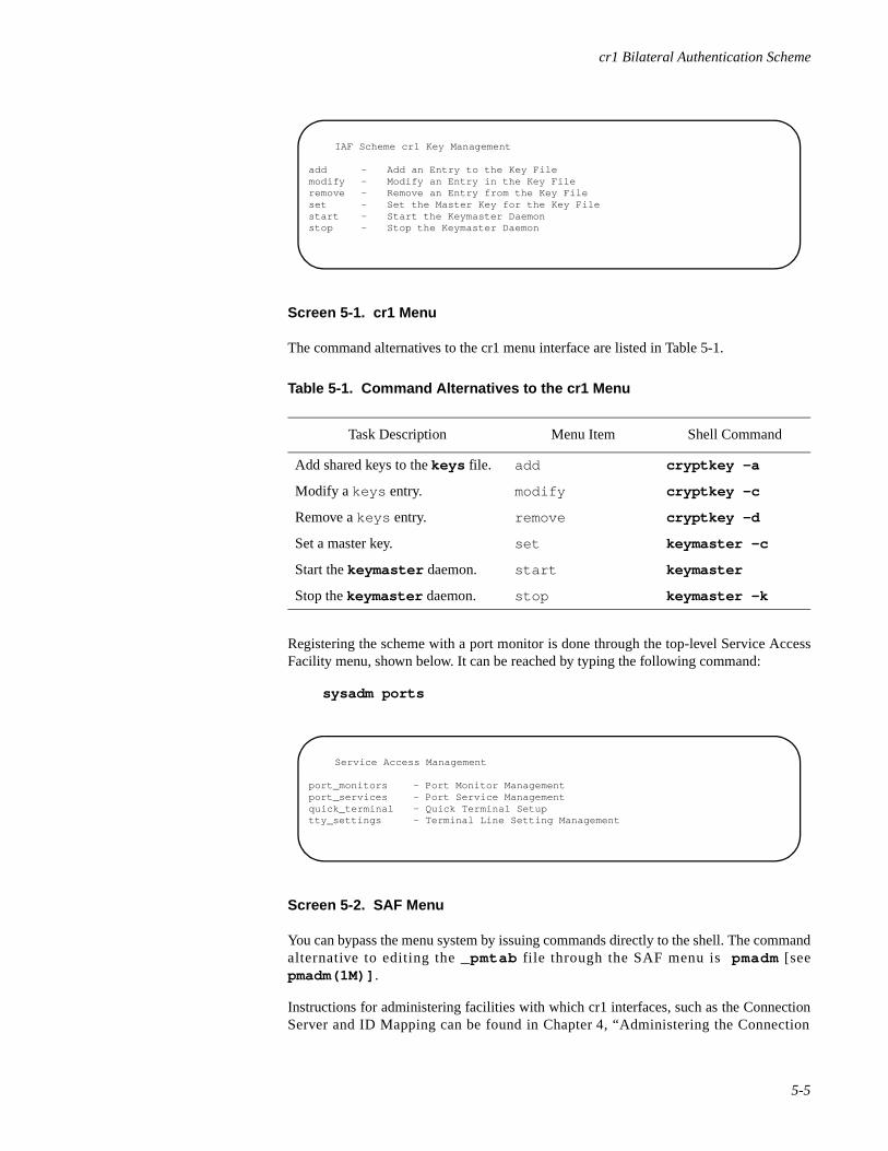
cr1 Bilateral Authentication Scheme
5-5
Screen 5-1. cr1 Menu
The command alternatives to the cr1 menu interface are listed in Table 5-1.
Registering the scheme with a port monitor is done through the top-level Service AccessFacility menu, shown below. It can be reached by typing the following command:
sysadm ports
Screen 5-2. SAF Menu
You can bypass the menu system by issuing commands directly to the shell. The commandalternative to editing the _pmtab file through the SAF menu is pmadm [seepmadm(1M)] .
Instructions for administering facilities with which cr1 interfaces, such as the ConnectionServer and ID Mapping can be found in Chapter 4, “Administering the Connection
Table 5-1. Command Alternatives to the cr1 Menu
Task Description Menu Item Shell Command
Add shared keys to the keys file. add cryptkey -a
Modify a keys entry. modify cryptkey -c
Remove a keys entry. remove cryptkey -d
Set a master key. set keymaster -c
Start the keymaster daemon. start keymaster
Stop the keymaster daemon. stop keymaster -k
IAF Scheme cr1 Key Management
add - Add an Entry to the Key Filemodify - Modify an Entry in the Key Fileremove - Remove an Entry from the Key Fileset - Set the Master Key for the Key Filestart - Start the Keymaster Daemonstop - Stop the Keymaster Daemon
Service Access Management
port_monitors - Port Monitor Managementport_services - Port Service Managementquick_terminal - Quick Terminal Setuptty_settings - Terminal Line Setting Management
Network Administration
5-6
Server” and Chapter 6, “Administering ID Mapping”, respectively. Because the menuinterface is self-explanatory, the following instructions assume you are administering cr1using shell commands.
Registering cr1 with a Port Monitor 5
To protect a local service with cr1, you must instruct the port monitor associated with theservice to use cr1 to authenticate any remote client attempting to gain access. To do this,you must add cr1 to the scheme field of the service's entry in the port monitor's _pmtabfile.
To specify cr1 in the scheme field of a file entry, enter the pmadm command and include
-S “cr1 -s servicetag”
on the command line.
NOTE
For more information about port monitors and the _pmtab file,see pmadm(1M) and the chapter “Managing Ports” in the SystemAdministration guide. This chapter includes specific instructionsfor editing _pmtab using the pmadm command.
Typically, cr1 in the role of the imposer is invoked with the -s option; however, a numberof options are supported. For a complete list of options, see cr1(1M) .
Registering cr1 with the Connection Server 5
Nothing needs to be done on the client side to register cr1. Once the cr1 executableprogram is installed, the Connection Server automatically invokes cr1 with the -r optionwhenever it receives a message from the server that cr1 is protecting the requested service.The -r option tells the program on the client that it is to play the role of the responder inthe authentication exchange.
When cr1 on the client is called, it searches local databases and sends pertinentinformation to the server, which the port monitor passes as arguments to the server's localcr1. Included in the arguments are the name of the user on the remote system and theremote system's machine name, which cr1 uses to locate the shared key in its key database.Setting up the key database is described in Setting Up the Key Database on page 5-8.
Although cr1 does not need to be administered on the client, the client administrator hasthe option to specify a list of acceptable schemes in the Connection Server's /etc/iaf/serve.allow file. If cr1 is specified, the Connection Server will fail the connection
cr1 Bilateral Authentication Scheme
5-7
request if the use of cr1 is not mandated by the server. By forcing the server to use cr1, theclient can verify the server's identity.
Instructions for setting up the /etc/iaf/serve.allow file can be found underChapter 4, “Administering the Connection Server”.
Managing the Daemon and the Master Key 5
Before you can administer the key database, the key management daemon must berunning. Typically, the daemon is started by default when you boot the system.
When you administer the key database—whether to add a new shared key to the keys file,delete a key that is no longer needed, or modify an existing key—the command you entercalls the key management daemon, which performs the requested operation. If you aresupplying a new shared key, for example, the daemon takes the shared key from thecryptkey command [see cryptkey(1) ] and stores it in the keys file. The daemonthen uses the master key to encrypt the keys in the keys file. Every time the daemonmodifies the keys file, it re-encrypts the keys—using the master key.
Both the key management daemon and the master key are managed using thekeymaster command [see keymaster(1M)], as described in the following sections.
Starting and Stopping the Daemon 5
The key management daemon is started automatically through an initialization scriptwhenever you boot the system; however, you can do this only if there is no master key.
NOTE
If you have a master key, the keymaster daemon cannot bestarted automatically at boot time; keymaster must be startedmanually. You must also edit the init script /etc/dinit.d/S69keymaster and comment out the line which readskeymaster -n .
If your system needs to be re-booted frequently, and you are unable to attend the systemduring a re-boot, you may want to store the keys file in unencrypted form. To store thekeys file in unencrypted form, you need to change the master key to NULL.
In certain circumstances—if there is a problem with the keys file, for example—you maywant to stop the daemon manually. Enter the keymaster command as follows to stop thedaemon:
keymaster -k
No key is required to stop the daemon; however, the operation fails if you are not theprivileged user (the owner of the keys file).
Network Administration
5-8
To re-start the daemon, enter the keymaster command.
Creating a Master Key 5
When cr1 is first installed and the system is booted, an initialization script runs the key-master command, which starts the key management daemon. Because the keys file isempty at this point, the master key is NULL.
To create the master key, simply enter the following command:
keymaster -n -c
keymaster prompts you for the key, which can be any alphanumeric string between zeroand eight characters in length.
When you enter the key, the keymaster command does not echo it on the screen.Instead, keymaster prompts you to enter the key a second time. If the first and secondentries match, the daemon stores the master key. If the entries do not match, the operationfails and the master key remains unchanged.
Once you create a master key, the daemon takes it and stores it. (For security reasons, itstores the key in cleartext in its process address space, not in a file. An encrypted copy ofthe master key is stored in the keys file.) The daemon then uses the master key to encryptthe shared keys in the keys file and to re-encrypt them every time the file is modified.
To change a master key once you have created it, enter
keymaster -c
The system then prompts you to enter the old master key. Once you enter the old masterkey, it prompts you to enter, and then re-enter the new master key. If the entries do notmatch, the operation fails and the master key remains unchanged.
Setting Up the Key Database 5
As described earlier, shared keys are stored in a keys file, which is set up and maintainedby the cr1 administrator. Whenever you administer the keys file, the key managementdaemon must be running.
Shared keys are stored in keys files on both the client and server machines. The cr1administrator of the client must enter a key to be shared by the local and remote systems.The cr1 administrator of the server machine must enter the same key into its key database.The database entry and the syntax of the command used to create the entry differ on theclient and server machines; however, the entry always includes the names of the twoprincipals in the exchange and, of course, the shared key. The key must be entered intoboth the client and server databases locally; there is no service available to propagate cr1keys on the network.
cr1 Bilateral Authentication Scheme
5-9
Typically, authentication is done at the system level. Authorization of individual users ismanaged locally. If there is a need to deny a user access to a service on a machine, the useris denied access locally, through the standard permissions mechanism.
Although we recommend restricting access through cr1 at the system level, access byindividual users can be controlled through cr1, as well. Shared keys can be entered into thekey database for individual users. If access is controlled through cr1 at the user level, userscan enter and maintain their own keys, in the same way that they maintain their own loginpasswords in /etc/shadow [see shadow(4) ].
The interface to the keys file is the cryptkey [see cryptkey(1) ] command. Thecryptkey command allows privileged and non-privileged users to add, delete, andmodify a key shared by two principals in a cr1 authentication exchange. A non-privilegeduser must be the local principal for whom the key is being added, deleted, or modified.The privileged user is the owner of the keys file. A privileged user can create, delete, ormodify keys for any user on the local system.
The cryptkey command has the following syntax:
cryptkey [-a | -c | -d] [ local_principal] remote_principal
For further information on the options, see cryptkey(1).
If cryptkey is entered without options, the -c option is assumed and an existing keyshared by the principals is modified.
When a user enters the command to add or change a key, he or she is prompted to enter anew key; the key can be any alphanumeric string between zero and eight characters inlength.
When a non-privileged user is deleting an old key, he or she is prompted to enter the oldkey. When changing a key, a non-privileged user is prompted to enter the old key, followedby the new key.
As with passwords, an administrator may need to change keys for users who do notremember their old keys, or remove keys belonging to users who no longer have access tothe system. Therefore a privileged user is not required to supply the old key whenchanging or deleting a key.
Assume you want to create a shared key for adam on your system, named eden, and fortom on a remote host named utopia. You want to enter serpent as the key. On theclient, you must do the following:
1. Enter
cryptkey -a adam utopia!tom
The system then prompts you to enter a key.
2. In response to the prompt, type serpent. The system then prompts youto enter the key a second time.
3. Enter serpent a second time. If the first and second entries match, thekey is added to the database. If they fail to match, the operation quits.
Network Administration
5-10
To add the key into the server's key database, you would do the following:
1. Access the server and enter
cryptkey -a tom eden!adam
Again, the system prompts you to enter a key.
2. Enter the same key that was added to the client's database—in this case,serpent
The system then prompts you to enter the key a second time.
3. Enter the key a second time. When you enter the key a second time, and thefirst and second entries match, the key is added to the server's key database.
Now the two principals have a shared key.
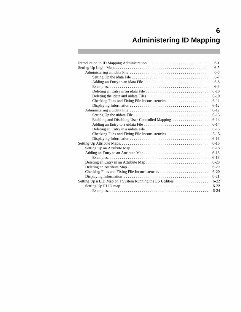
6Administering ID Mapping
Introduction to ID Mapping Administration . . . . . . . . . . . . . . . . . . . . . . . . . . . . . . . 6-1Setting Up Login Maps . . . . . . . . . . . . . . . . . . . . . . . . . . . . . . . . . . . . . . . . . . . . . . . 6-5
Administering an idata File . . . . . . . . . . . . . . . . . . . . . . . . . . . . . . . . . . . . . . . . 6-6Setting Up the idata File . . . . . . . . . . . . . . . . . . . . . . . . . . . . . . . . . . . . . . . 6-7Adding an Entry to an idata File . . . . . . . . . . . . . . . . . . . . . . . . . . . . . . . . . 6-8Examples . . . . . . . . . . . . . . . . . . . . . . . . . . . . . . . . . . . . . . . . . . . . . . . . . . . 6-9Deleting an Entry in an idata File . . . . . . . . . . . . . . . . . . . . . . . . . . . . . . . . 6-10Deleting the idata and uidata Files . . . . . . . . . . . . . . . . . . . . . . . . . . . . . . . 6-10Checking Files and Fixing File Inconsistencies . . . . . . . . . . . . . . . . . . . . . 6-11Displaying Information . . . . . . . . . . . . . . . . . . . . . . . . . . . . . . . . . . . . . . . . 6-12
Administering a uidata File . . . . . . . . . . . . . . . . . . . . . . . . . . . . . . . . . . . . . . . . 6-12Setting Up the uidata File . . . . . . . . . . . . . . . . . . . . . . . . . . . . . . . . . . . . . . 6-13Enabling and Disabling User-Controlled Mapping. . . . . . . . . . . . . . . . . . . 6-14Adding an Entry to a uidata File . . . . . . . . . . . . . . . . . . . . . . . . . . . . . . . . . 6-14Deleting an Entry in a uidata File . . . . . . . . . . . . . . . . . . . . . . . . . . . . . . . . 6-15Checking Files and Fixing File Inconsistencies . . . . . . . . . . . . . . . . . . . . . 6-15Displaying Information . . . . . . . . . . . . . . . . . . . . . . . . . . . . . . . . . . . . . . . . 6-16
Setting Up Attribute Maps. . . . . . . . . . . . . . . . . . . . . . . . . . . . . . . . . . . . . . . . . . . . . 6-16Setting Up an Attribute Map . . . . . . . . . . . . . . . . . . . . . . . . . . . . . . . . . . . . . . . 6-18Adding an Entry to an Attribute Map. . . . . . . . . . . . . . . . . . . . . . . . . . . . . . . . . 6-18
Examples . . . . . . . . . . . . . . . . . . . . . . . . . . . . . . . . . . . . . . . . . . . . . . . . . . . 6-19Deleting an Entry in an Attribute Map . . . . . . . . . . . . . . . . . . . . . . . . . . . . . . . . 6-20Deleting an Attribute Map . . . . . . . . . . . . . . . . . . . . . . . . . . . . . . . . . . . . . . . . . 6-20Checking Files and Fixing File Inconsistencies . . . . . . . . . . . . . . . . . . . . . . . . . 6-20Displaying Information . . . . . . . . . . . . . . . . . . . . . . . . . . . . . . . . . . . . . . . . . . . 6-21
Setting Up a LID Map on a System Running the ES Utilities . . . . . . . . . . . . . . . . . 6-22Setting Up RLID.map. . . . . . . . . . . . . . . . . . . . . . . . . . . . . . . . . . . . . . . . . . . . . 6-22
Examples . . . . . . . . . . . . . . . . . . . . . . . . . . . . . . . . . . . . . . . . . . . . . . . . . . . 6-24

Network Administration
6-1
6Chapter 6Administering ID Mapping
666
Introduction to ID Mapping Administration 6
ID Mapping is a facility that can be used to establish local identities for users on remotesystems. It provides a common mechanism through which applications can identifyremote users and control remote access to local resources.
The ID Mapping module consists of two routines that map remote users into localidentities, plus a database from which the routines retrieve the relevant mappinginformation. The ID Mapping database includes two types of map files. One type containsentries that map user logins; the other contains entries that map the values of userattributes, such as UIDs and GIDs.
When a remote user attempts to access a service on your system, the port monitor receivesthe connection request. It uses an authentication scheme to validate the user; the schemethen calls the ID Mapping routines. One routine checks the login maps associated with theID Mapping scheme, then maps the user to a login on the local system. The other routinechecks the local system's attribute maps, then maps the values of user attributes on theremote system to the specified local values.
Both login mapping and attribute mapping are provided as part of a general mappingfacility. Some applications may require that users be mapped by login, some by attributes,and some by both. On a system running the Enhanced Security Utilities, users are mappedboth by login and by security level ID (LID). If the Least Privilege Module (LPM) isrunning, the ID Mapping administrator must be in the NET role and be a member of groupsys. LPM is part of the Enhanced Security Utilities.
ID Mapping administration entails setting up and maintaining the ID Mapping database;however, before you set up the database, it is assumed you have installed theauthentication schemes you intend to use.
NOTE
The cr1 authentication scheme is the only authentication schemeprovided at this time—with the exception of the traditional login/password scheme, which doesn't rely on ID Mapping. Unlessotherwise stated, examples throughout the discussion of ID Map-ping assume cr1 is the authentication scheme.
We recommend you administer your system in the following sequence:
1. Check that authentication scheme executable programs are installed in theproper directories; cr1 should be installed in /usr/lib/iaf/cr1.
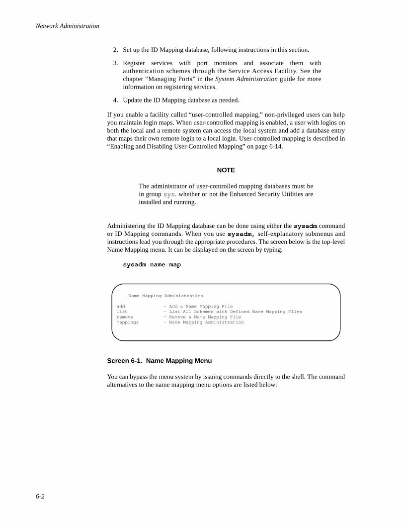
Network Administration
6-2
2. Set up the ID Mapping database, following instructions in this section.
3. Register services with port monitors and associate them withauthentication schemes through the Service Access Facility. See thechapter “Managing Ports” in the System Administration guide for moreinformation on registering services.
4. Update the ID Mapping database as needed.
If you enable a facility called “user-controlled mapping,” non-privileged users can helpyou maintain login maps. When user-controlled mapping is enabled, a user with logins onboth the local and a remote system can access the local system and add a database entrythat maps their own remote login to a local login. User-controlled mapping is described in“Enabling and Disabling User-Controlled Mapping” on page 6-14.
NOTE
The administrator of user-controlled mapping databases must bein group sys . whether or not the Enhanced Security Utilities areinstalled and running.
Administering the ID Mapping database can be done using either the sysadm commandor ID Mapping commands. When you use sysadm, self-explanatory submenus andinstructions lead you through the appropriate procedures. The screen below is the top-levelName Mapping menu. It can be displayed on the screen by typing:
sysadm name_map
Screen 6-1. Name Mapping Menu
You can bypass the menu system by issuing commands directly to the shell. The commandalternatives to the name mapping menu options are listed below:
Name Mapping Administration
add - Add a Name Mapping Filelist - List All Schemes with Defined Name Mapping Filesremove - Remove a Name Mapping Filemappings - Name Mapping Administration
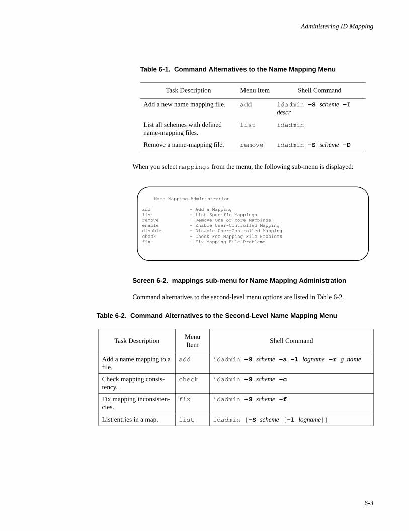
Administering ID Mapping
6-3
When you select mappings from the menu, the following sub-menu is displayed:
Screen 6-2. mappings sub-menu for Name Mapping Administration
Command alternatives to the second-level menu options are listed in Table 6-2.
Table 6-1. Command Alternatives to the Name Mapping Menu
Task Description Menu Item Shell Command
Add a new name mapping file. add idadmin -S scheme -I descr
List all schemes with defined name-mapping files.
list idadmin
Remove a name-mapping file. remove idadmin -S scheme -D
Table 6-2. Command Alternatives to the Second-Level Name Mapping Menu
Task DescriptionMenu Item
Shell Command
Add a name mapping to a file.
add idadmin -S scheme -a -l logname -r g_name
Check mapping consis-tency.
check idadmin -S scheme -c
Fix mapping inconsisten-cies.
fix idadmin -S scheme -f
List entries in a map. list idadmin [ -S scheme [ -l logname]]
Name Mapping Administration
add - Add a Mappinglist - List Specific Mappingsremove - Remove One or More Mappingsenable - Enable User-Controlled Mappingdisable - Disable User-Controlled Mappingcheck - Check For Mapping File Problemsfix - Fix Mapping File Problems
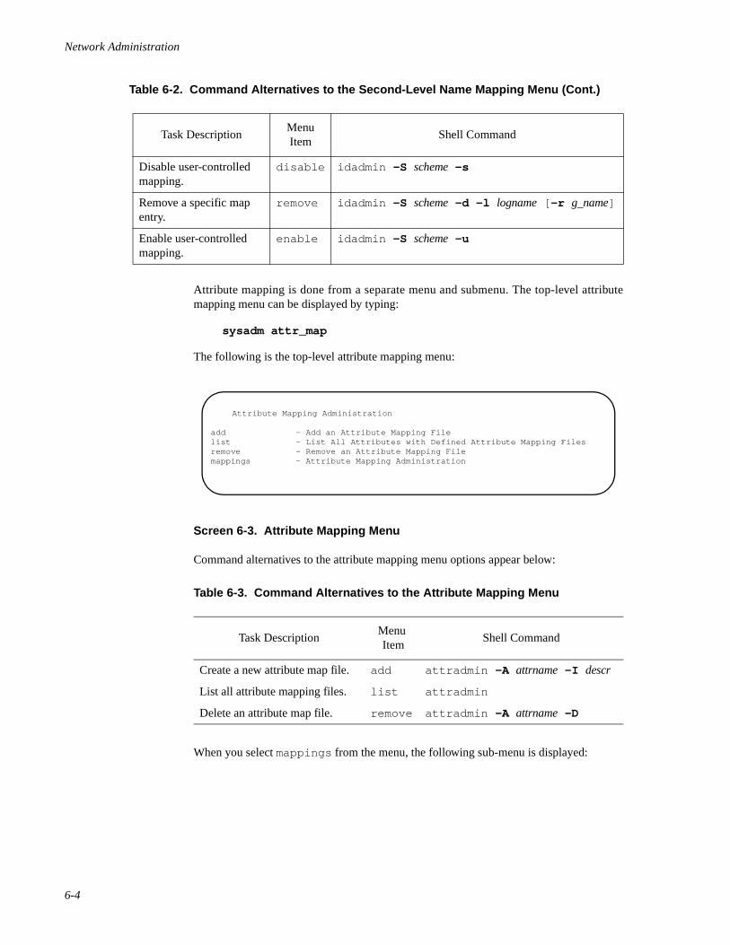
Network Administration
6-4
Attribute mapping is done from a separate menu and submenu. The top-level attributemapping menu can be displayed by typing:
sysadm attr_map
The following is the top-level attribute mapping menu:
Screen 6-3. Attribute Mapping Menu
Command alternatives to the attribute mapping menu options appear below:
When you select mappings from the menu, the following sub-menu is displayed:
Disable user-controlled mapping.
disable idadmin -S scheme -s
Remove a specific map entry.
remove idadmin -S scheme -d -l logname [ -r g_name]
Enable user-controlled mapping.
enable idadmin -S scheme -u
Table 6-3. Command Alternatives to the Attribute Mapping Menu
Task DescriptionMenu Item
Shell Command
Create a new attribute map file. add attradmin -A attrname -I descr
List all attribute mapping files. list attradmin
Delete an attribute map file. remove attradmin -A attrname -D
Table 6-2. Command Alternatives to the Second-Level Name Mapping Menu (Cont.)
Task DescriptionMenu Item
Shell Command
Attribute Mapping Administration
add - Add an Attribute Mapping Filelist - List All Attributes with Defined Attribute Mapping Filesremove - Remove an Attribute Mapping Filemappings - Attribute Mapping Administration
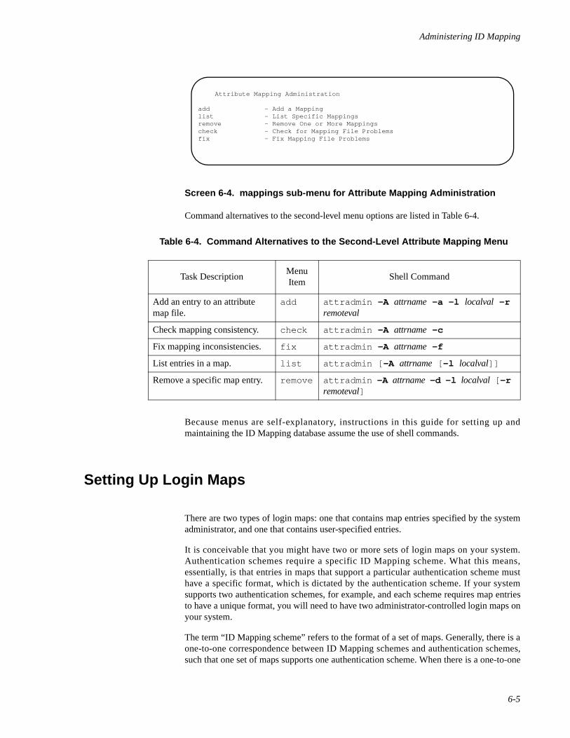
Administering ID Mapping
6-5
Screen 6-4. mappings sub-menu for Attribute Mapping Administration
Command alternatives to the second-level menu options are listed in Table 6-4.
Because menus are self-explanatory, instructions in this guide for setting up andmaintaining the ID Mapping database assume the use of shell commands.
Setting Up Login Maps 6
There are two types of login maps: one that contains map entries specified by the systemadministrator, and one that contains user-specified entries.
It is conceivable that you might have two or more sets of login maps on your system.Authentication schemes require a specific ID Mapping scheme. What this means,essentially, is that entries in maps that support a particular authentication scheme musthave a specific format, which is dictated by the authentication scheme. If your systemsupports two authentication schemes, for example, and each scheme requires map entriesto have a unique format, you will need to have two administrator-controlled login maps onyour system.
The term “ID Mapping scheme” refers to the format of a set of maps. Generally, there is aone-to-one correspondence between ID Mapping schemes and authentication schemes,such that one set of maps supports one authentication scheme. When there is a one-to-one
Table 6-4. Command Alternatives to the Second-Level Attribute Mapping Menu
Task DescriptionMenu Item
Shell Command
Add an entry to an attribute map file.
add attradmin -A attrname -a -l localval -r remoteval
Check mapping consistency. check attradmin -A attrname -c
Fix mapping inconsistencies. fix attradmin -A attrname -f
List entries in a map. list attradmin [ -A attrname [ -l localval]]
Remove a specific map entry. remove attradmin -A attrname -d -l localval [ -r remoteval]
Attribute Mapping Administration
add - Add a Mappinglist - List Specific Mappingsremove - Remove One or More Mappingscheck - Check for Mapping File Problemsfix - Fix Mapping File Problems
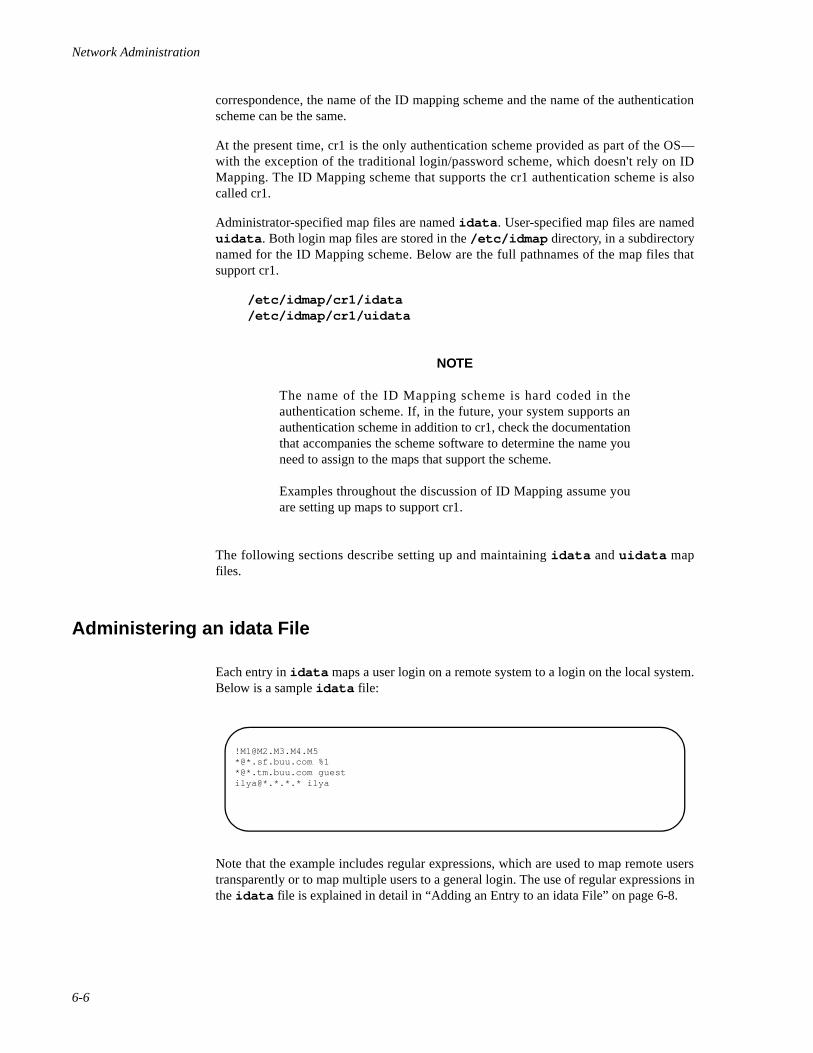
Network Administration
6-6
correspondence, the name of the ID mapping scheme and the name of the authenticationscheme can be the same.
At the present time, cr1 is the only authentication scheme provided as part of the OS—with the exception of the traditional login/password scheme, which doesn't rely on IDMapping. The ID Mapping scheme that supports the cr1 authentication scheme is alsocalled cr1.
Administrator-specified map files are named idata . User-specified map files are nameduidata . Both login map files are stored in the /etc/idmap directory, in a subdirectorynamed for the ID Mapping scheme. Below are the full pathnames of the map files thatsupport cr1.
/etc/idmap/cr1/idata/etc/idmap/cr1/uidata
NOTE
The name of the ID Mapping scheme is hard coded in theauthentication scheme. If, in the future, your system supports anauthentication scheme in addition to cr1, check the documentationthat accompanies the scheme software to determine the name youneed to assign to the maps that support the scheme.
Examples throughout the discussion of ID Mapping assume youare setting up maps to support cr1.
The following sections describe setting up and maintaining idata and uidata mapfiles.
Administering an idata File 6
Each entry in idata maps a user login on a remote system to a login on the local system.Below is a sample idata file:
Note that the example includes regular expressions, which are used to map remote userstransparently or to map multiple users to a general login. The use of regular expressions inthe idata file is explained in detail in “Adding an Entry to an idata File” on page 6-8.
[email protected]*@*.sf.buu.com %1*@*.tm.buu.com guestilya@*.*.*.* ilya
Administering ID Mapping
6-7
All entries in an idata file are specified by the system administrator. When a remote userhas an entry in idata , he or she can access a service on the local system and assume theuser identity defined by the administrator.
The idadmin command is the command interface to idata. It allows a privileged userto do the following:
• create and delete an idata file for a particular ID Mapping scheme
• add and delete user entries in an idata file
• display information about the idata files
• check the consistency of file entries and fix inconsistencies
• enable and disable user-controlled mapping.
NOTE
If the Least Privilege Module (LPM) is running, the ID Mappingadministrator must be in the NET role and be a member of groupsys. LPM is part of the Enhanced Security Utilities.
The idadmin command has the following syntax:
idadmin [-S scheme [-l logname]]idadmin -S scheme -a -l logname -r g_nameidadmin -S scheme -d -l logname [-r g_name]idadmin -S scheme -I descridadmin -S scheme [-Duscf]
See idadmin(1M) for an explanation of the options accepted by the idadmincommand.
The options and command syntax required to execute a particular operation are describedin the following sections.
Setting Up the idata File 6
When you want to set up an idata map file for a particular ID Mapping scheme, youmust enter the idadmin command with the ID Mapping scheme name and specify theformat that the global name should take in all file entries.
The idadmin command has the following syntax when used to set up a new file:
idadmin -S scheme -I descr
where scheme is the name of the ID Mapping scheme, and descr is a string called a formatdescriptor. The string specifies the form that the name of the remote user must take in theidata map file.

Network Administration
6-8
For example, cr1 expects global names to consist of the user's login, followed by thecharacter @, then the system name. The global name of a user with the login jeff on amachine called moon would be
jeff@moon
The format descriptor itself consists of field numbers, the letter M, indicating the fields aremandatory, and the character(s) that are used as field separators.
The file descriptor you would enter to set up an idata file for cr1 would be
M1@M2
The field numbers indicate the order of significance of the fields, where higher numberedfields are more significant. In the example, M2 means that the entity to be specified in thesecond field is of greater significance on the network than the entity specified in the firstfield. In this case, the system is of greater significance than the user. The letter M indicatesthat the fields are required when specifying g_name.
Assume that BNU services are registered with the authentication scheme cr1. To set up anidata file that would map remote users to the local system and give them access to BNU,you would enter the following command:
idadmin -S cr1 -I M1@M2
When the idadmin command in the example is executed, it creates the file /etc/idmap/cr1/idata . The first line of the file consists of the format descriptor. Except forthe format descriptor, the file is empty until user entries are added, as described in the fol-lowing section.
Adding an Entry to an idata File 6
To map a remote user to a login on the local system, add an entry for the remote user to theappropriate idata file. The local login must be in the /etc/passwd file on the localsystem.
When you add a user entry to idata, idadmin has the syntax
idadmin -S scheme -a -l logname -r g_name
where scheme is the name of the ID mapping scheme, g_name is the global name of theremote user, and logname is the local login. For example, given the format descriptorM1@M2, the following entry maps jeff on machine moon to the local login guest:
idadmin -S cr1 -a -l guest -r jeff@moon
You can set up transparent mapping of logins by using regular expressions in the g_namefield and the % character in the logname field. The special characters supported by theidadmin command are explained on idadmin(1M).
File entries are sorted so that an entry that maps a login explicitly is found in a searchbefore entries that implement transparent mapping. Likewise, entries that map loginstransparently are sorted based on the position of the regular expression in the global name.Entries with a regular expression in place of a remote user login appear in the file beforeentries with a regular expression in place of a system name.

Administering ID Mapping
6-9
Examples6
Assume the ID Mapping scheme is idmp and g_name has the form [email protected], where M1indicates the user's login. The following command line transparently maps all users on theremote system man in the domain moon. All users are mapped to the local login guest .
idadmin -S idmp -a -l guest -r “*@man.moon”
NOTE
To protect characters that are meaningful to the shell, enclose glo-bal names in quotes.
If you enter * in place of the remote user name and %1 in place of logname on theidadmin command line, you map all remote logins to the same values indicated in M1.Assume the authentication scheme is called cr2 and the format descriptor is M2:M1. Ifyou want to map all logins on pluto to identical logins on your machine, you wouldenter
idadmin -S cr2 -a -l %1 -r “pluto:*”
In this example, user bob on the remote system would be mapped to bob on the localsystem; johnd on the remote system would be mapped to johnd , and so on.
In the next example, assume you want to map all logins on remote system mars toidentical logins on your system, with the exception of the remote login guest.Assuming cr1 is the authentication scheme, the map must contain the following pair ofentries:
guest@mars %i*@mars %1
To add the entries to the map, first enter
idadmin -S cr1 -a -l %i -r guest@mars
Then enter
idadmin -S cr1 -a -l %1 -r “*@mars”
These entries could have been added in reverse order. The idadmin command ensuresthat the most specific entry appears first in the file. If you enter %i in place of logname onthe idadmin command line, the remote user specified by the -r would be rejected.
Other characters can appear in a field containing an asterisk. For example, all remotesystem names beginning with ux will match the pattern ux* . The following commandadds transparent mapping for all users on machines with names being with ux .
idadmin -S cr1 -a -l %1 -r “*@ux*”
In addition, to exclude all guest users on these remote systems, enter
idadmin -S cr1 -a -l %i -r “guest@ux*”

Network Administration
6-10
The contents of an idata file with these four entries would be
When an idata file is searched for a global name, it is scanned sequentially. Thereforethe ordering of global names in this file is critical.
Global names are sorted on the highest numbered field first. Entries with explicit values inthis field appear first in the file. Entries with regular expressions in this field appear nextand are sorted from most specific to least specific. For example, the remote system nameux* is more specific than the remote system name u* and therefore would appear first inthe file.
If two or more entries are equally specific, the specificity of the next lower numbered fieldis examined. Fields are examined from highest to lowest until the global names can be dif-ferentiated.
NOTE
Remote IDs should not be mapped to uucp . Instead, they shouldbe mapped to nuucp or some other login used exclusively fordata transfer.
Deleting an Entry in an idata File 6
To delete an entry in idata, enter idadmin with the following syntax:
idadmin -S scheme -d -l logname [ -r g_name]
where scheme is the name of the ID mapping scheme, g_name is the global name of theremote user, and logname is the local login.
The use of -r is optional. If you enter the command without the -r option, every entryassociated with the local login is deleted. If g_name is specified with the -r option, onlythe entry that maps the specified remote user to the specified local login is deleted.
For example, to delete all entries in /etc/idmap/cr1/idata that map remote users tothe local login guest, you would enter
idadmin -S cr1 -d -l guest
Deleting the idata and uidata Files 6
To delete the idata and uidata files (removing a scheme), enter the idadmin with thesyntax
M1@M2guest@mars %i*@mars %1guest@ux* %i*@ux* %1
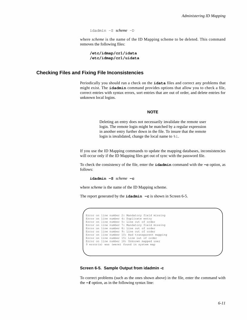
Administering ID Mapping
6-11
idadmin -S scheme -D
where scheme is the name of the ID Mapping scheme to be deleted. This commandremoves the following files:
/etc/idmap/cr1/idata/etc/idmap/cr1/uidata
Checking Files and Fixing File Inconsistencies 6
Periodically you should run a check on the idata files and correct any problems thatmight exist. The idadmin command provides options that allow you to check a file,correct entries with syntax errors, sort entries that are out of order, and delete entries forunknown local logins.
NOTE
Deleting an entry does not necessarily invalidate the remote userlogin. The remote login might be matched by a regular expressionin another entry further down in the file. To insure that the remotelogin is invalidated, change the local name to %i.
If you use the ID Mapping commands to update the mapping databases, inconsistencieswill occur only if the ID Mapping files get out of sync with the password file.
To check the consistency of the file, enter the idadmin command with the -c option, asfollows:
idadmin -S scheme -c
where scheme is the name of the ID Mapping scheme.
The report generated by the idadmin -c is shown in Screen 6-5.
Screen 6-5. Sample Output from idadmin -c
To correct problems (such as the ones shown above) in the file, enter the command withthe -f option, as in the following syntax line:
Error on line number 2: Mandatory field missingError on line number 4: Duplicate entryError on line number 5: Line out of orderError on line number 7: Mandatory field missingError on line number 8: Line out of orderError on line number 9: Line out of orderError on line number 10: Bad transparent mappingError on line number 15: Line out of orderError on line number 18: Unknown mapped user9 error(s) was (were) found in system map
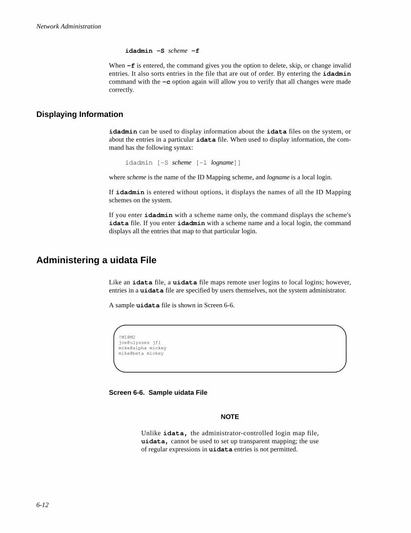
Network Administration
6-12
idadmin -S scheme -f
When -f is entered, the command gives you the option to delete, skip, or change invalidentries. It also sorts entries in the file that are out of order. By entering the idadmincommand with the -c option again will allow you to verify that all changes were madecorrectly.
Displaying Information 6
idadmin can be used to display information about the idata files on the system, orabout the entries in a particular idata file. When used to display information, the com-mand has the following syntax:
idadmin [-S scheme [-l logname]]
where scheme is the name of the ID Mapping scheme, and logname is a local login.
If idadmin is entered without options, it displays the names of all the ID Mappingschemes on the system.
If you enter idadmin with a scheme name only, the command displays the scheme'sidata file. If you enter idadmin with a scheme name and a local login, the commanddisplays all the entries that map to that particular login.
Administering a uidata File 6
Like an idata file, a uidata file maps remote user logins to local logins; however,entries in a uidata file are specified by users themselves, not the system administrator.
A sample uidata file is shown in Screen 6-6.
Screen 6-6. Sample uidata File
NOTE
Unlike idata, the administrator-controlled login map file,uidata, cannot be used to set up transparent mapping; the useof regular expressions in uidata entries is not permitted.
!M1@M2joe@ulysses jflmike@alpha mickeymike@beta mickey
Administering ID Mapping
6-13
When you enable user-controlled mapping, a user with logins on both a remote system andthe local system can access the local system and make an entry in uidata that maps hisor her remote login to a local login. By enabling user-controlled mapping and instructingusers to update the database, an administrator can distribute the workload and minimizethe administrative overhead. For more information about user-controlled mapping, see“Enabling and Disabling User-Controlled Mapping” on page 6-14.
The uidadmin command is the command interface to uidata. When entered by a user,assuming user-controlled mapping is enabled, the non-privileged user can do thefollowing:
• add and delete his or her entries
• display his or her entries.
An administrator can use the uidadmin command to
• display all the entries in a uidata file
• check the consistency of file entries and fix inconsistencies
• add or delete an entry on behalf of a non-privileged user
NOTE
The administrator of user-controlled mapping must be in groupsys . This is required whether or not the Enhanced SecurityUtilities are installed and running.
The uidadmin command has the following syntax:
uidadmin [ -S scheme [ -l logname]]uidadmin -S scheme -a [ -l logname] -r g_nameuidadmin -S scheme -d -l logname [ -r g_name]uidadmin -S scheme [ -cf ]
See uidadmin(1) for an explanation of the options accepted by the uidadmincommand.
The options and command syntax required to execute a particular operation are describedin the following sections.
Setting Up the uidata File 6
A uidata file is set up for a particular authentication scheme when you set up thescheme's idata file, using the idadmin command. For example, to set up an idata filefor cr1, you enter the following:
idadmin -S cr1 -I M1@M2
When the command executes, a uidata file is created in /etc/idmap/cr1, alongwith an idata file; however, users cannot add entries to the file, nor will the name
Network Administration
6-14
mapping function attempt to read the file, until user-controlled mapping is enabled, asdescribed in the following section.
Enabling and Disabling User-Controlled Mapping 6
When user-controlled mapping is disabled, every time a remote user attempts to access thelocal system, an internal routine searches the appropriate idata file for a map entry forthat user. When user-controlled mapping is enabled, the uidata file is searched first.Because any entry in uidata relevant to the remote user is found before an entry inidata, the entry in uidata takes precedence over the idata entry. In this way, theuser-specified mapping overrides an administrator-specified mapping for that user. Whenuser-controlled mapping is disabled, uidata is not searched at all.
Whenever maps for a new ID Mapping scheme are set up, user-controlled mapping isdisabled. Before enabling user-controlled mapping, create local logins for your remoteusers.
To enable user-controlled mapping for a particular authentication scheme, you enteridadmin with the -u option, as in the following syntax line:
idadmin -S scheme -u
where scheme is the name of the ID Mapping scheme. This command activates the USERmode of the authentication scheme.
To disable user-controlled mapping, you enter idadmin with the -s option, as in thefollowing line:
idadmin -S scheme -s
This command activates the SECURE mode of the authentication scheme. Whenidadmin is entered without options, it lists all schemes and indicates whether each is inUSER or SECURE mode. A scheme in SECURE mode has user-controlled mappingdisabled.
Adding an Entry to a uidata File 6
When user-controlled mapping is enabled, non-privileged users with logins on the localsystem can map their own logins on a remote system to their own local logins. A non-privileged user cannot add entries for other users.
When used to add an entry to a uidata file, the uidadmin command has the syntax.
uidadmin -S scheme -a [ -l logname] -r g_name
where scheme is the name of the ID mapping scheme, g_name is a global name thatincludes the remote login, and logname is the local login. A non-privileged user ispermitted to map a remote login only to his or her local login; if the -l option is omitted,the user's local login is assumed.
Administering ID Mapping
6-15
NOTE
If the administrator enters the uidadmin command to add anentry on behalf of a non-privileged user, the -l option is required.
In the following example, a user named Mike has logins on two systems. His login on amachine called wizard is michael; his login on a machine called zooey is mike.Mike wants to map his login on wizard to his login on zooey. The service he wants toaccess on zooey is associated with the cr1 authentication scheme. To set up mappingfrom wizard to zooey, Mike would access zooey and enter the following command:
uidadmin -S cr1 -a -r michael@wizard
Deleting an Entry in a uidata File 6
When user-controlled mapping is enabled, any non-privileged user may choose to deletean entry mapping his or her login; however, a non-privileged user cannot delete entriesmade by another user.
If a user also has a map entry in the administrator-controlled idata file, he or she will bemapped to the login specified in that entry once the uidata entry has been deleted.
When used to delete an entry, the uidadmin command has the following syntax:
uidadmin -S scheme -d -l logname [ -r g_name]
where scheme is the name of the ID Mapping scheme, and logname is the local login.
The use of g_name is optional. If g_name is omitted, every entry that maps a remote loginto the specified local login is deleted from the uidata file. If g_name is specified, onlythe entry that maps that global name to the local login is deleted.
If user Mike wants to delete the entry that maps his login michael on wizard to mikeon zooey , he would enter the following:
uidadmin -S cr1 -d -l mike -r michael@wizard
Checking Files and Fixing File Inconsistencies 6
Because there is no need for your users to edit the uidadmin file directly, there is littledanger that the file will become cluttered with entries containing syntax errors; however,you should run a check on the file periodically and correct any problems that might exist.The uidadmin command provides options that allow an administrator to check the file,correct entries with syntax errors, and delete entries that map to unknown logins.
To check the consistency of the file, enter uidadmin with the following options:
uidadmin -S scheme -c
where scheme is the name of the ID Mapping scheme.
To correct the problems in the file, enter the command with the following options:
Network Administration
6-16
uidadmin -S scheme -f
When the -f option is entered, uidadmin gives you the opportunity to replace entriesthat contain syntax errors and to delete entries associated with logins that do not exist in/etc/passwd. It then sorts entries that are out of order. Entering uidadmin with the-c option again will verify that all changes were done correctly.
Displaying Information 6
Both the system administrator and a non-privileged user may use the uidadmincommand to display information. When used to display information, the command has thefollowing syntax:
uidadmin [-S scheme [-l logname]]
where scheme is the name of the ID Mapping scheme, and logname is a local login.
If uidadmin is entered without options, it displays the names of all the ID Mappingschemes on the system. If an administrator enters uidadmin with a scheme name only,the command displays the uidadmin file associated with the specified scheme. If theadministrator enters uidadmin with a scheme name and a local login, the commanddisplays all entries that map remote logins to the specified local login.
If a non-privileged user enters uidadmin with only a scheme name, the command dis-plays only the entries in uidata associated with his or her local login.
Setting Up Attribute Maps 6
Attribute map files map the values of user attributes on a remote system to attribute valueson the local system. Most likely, an authentication scheme that maps user attributes willmap such attributes as UID, GID, and LID.
Attribute maps are created in the /etc/idmap/attrmap directory. Generally, you'llname each file for the attribute it maps.
NOTE
The names of the attribute map files must match the name used inthe authentication scheme. For example, on a system on which theEnhanced Security Utilities are installed and running, cr1 requiresa file that maps remote LIDs called RLID.map. If your systemsupports an application that uses attribute mapping, check thedocumentation that accompanies the scheme software todetermine the names you should give the map files.
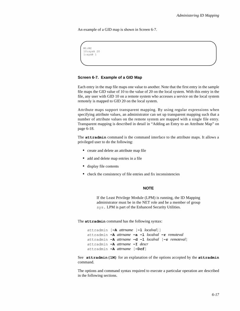
Administering ID Mapping
6-17
An example of a GID map is shown in Screen 6-7.
Screen 6-7. Example of a GID Map
Each entry in the map file maps one value to another. Note that the first entry in the samplefile maps the GID value of 10 to the value of 20 on the local system. With this entry in thefile, any user with GID 10 on a remote system who accesses a service on the local systemremotely is mapped to GID 20 on the local system.
Attribute maps support transparent mapping. By using regular expressions whenspecifying attribute values, an administrator can set up transparent mapping such that anumber of attribute values on the remote system are mapped with a single file entry.Transparent mapping is described in detail in “Adding an Entry to an Attribute Map” onpage 6-18.
The attradmin command is the command interface to the attribute maps. It allows aprivileged user to do the following:
• create and delete an attribute map file
• add and delete map entries in a file
• display file contents
• check the consistency of file entries and fix inconsistencies
NOTE
If the Least Privilege Module (LPM) is running, the ID Mappingadministrator must be in the NET role and be a member of groupsys. LPM is part of the Enhanced Security Utilities.
The attradmin command has the following syntax:
attradmin [ -A attrname [ -l localval]]attradmin -A attrname -a -l localval -r remotevalattradmin -A attrname -d -l localval [ -r remoteval]attradmin -A attrname -I descrattradmin -A attrname [ -Dcf ]
See attradmin(1M) for an explanation of the options accepted by the attradmincommand.
The options and command syntax required to execute a particular operation are describedin the following sections.
M1:M210:sysA 201:sysB 1
Network Administration
6-18
Setting Up an Attribute Map 6
If you want to set up an attribute map file, you must enter the attradmin command withthe attribute map filename and specify the format the remote value should take in all mapentries.
When the attradmin command is used to set up a new file, it has the following syntax:
attradmin -A attrname -I descr
where attrname is the name of the attribute, and descr is a string called a format descriptor.The format descriptor specifies the format in which the remote attribute value must beentered when a map entry is created.
If you're using cr1 as your authentication scheme, the format descriptor you need to enteris M1@M2.
NOTE
At this t ime, the cr1 authent ication scheme is the onlyauthentication scheme provided—with the exception of thetraditional login/password scheme, which doesn't rely on IDMapping. Unless otherwise stated, examples throughout thediscussion of ID Mapping assume cr1 as the authenticationscheme.
Field numbers indicate the order of significance of the fields. Higher numbered fields arethe more significant. M2 in the descriptor M1@M2 means that the second field contains anentity of greater significance on the network than does the first field. The letter M indicatesthat the fields are required. The @ symbol is a field separator. For example, given theformat descriptor M1@M2, UID 104 on the remote system venus would be specified as104@venus.
To set up a map file that maps UIDs on remote systems to UIDs on the local system, youmight enter the following command line:
attradmin -A uid -I M1@M2
Once the command executes, the file uid.map appears in /etc/idmap/attrmap , andthe format descriptor appears in the first line of the file.
Adding an Entry to an Attribute Map 6
To add an entry that maps a remote attribute value to a local value, you enter attradminwith the syntax
attradmin -A attrname -a -l localval -r remoteval
where attrname is the name of the attribute, remoteval is the combination of an attributevalue on the remote system and the remote system name, and localval is the attribute value
Administering ID Mapping
6-19
on the local system. For example, the following command line maps GID 10 on the remotesystem moon to a GID 20 on the local system:
attradmin -A gid -a -l 20 -r 10@moon
Once the command executes, any user with a GID of 10 on moon has a GID of 20 on thelocal system.
You can set up transparent mapping of attributes by using regular expressions in theremoteval and special characters in the localval field. The characters supported by theattradmin command are explained on attradmin(1M).
File entries are sorted so an entry that maps a value explicitly is found in a search beforeentries that implement transparent mapping. Likewise, entries that map valuestransparently are sorted based on the position of the regular expression in remote_attr.Entries with a regular expression in place of a remote attribute value appear in the filebefore entries with a regular expression in place of a system name.
The attradmin command sorts entries containing regular expressions in remote_attr inthe same way the idadmin command sorts entries containing regular expressions in theglobal name, with one addition: fields with regular expressions containing brackets, [@,are considered more specific than fields with an asterisk and therefore will precede fieldscontaining an asterisk. See “Adding an Entry to an idata File” on page 6-8.
Examples 6
The following command line transparently maps all GIDs on the remote system mars toGID 10 on the local system.
attradmin -A gid -a -l 10 -r “*@mars”
NOTE
To protect characters that are meaningful to the shell, encloseremoteval in quotes.
Given the format descriptor M1@M2, the following command line maps all UID values onthe remote system mars to identical values on the local system.
attradmin -A uid -a -l %1 -r “*@mars”
In this example, UID 101 on mars is mapped to UID 101 on the local machine, UID 102is mapped to UID 102, and so on.
By using a regular expression in place of a remote machine name, you can map values onevery machine on the network with access to your system to identical local values. Thefollowing command line maps all remote UIDs to the same UIDs on the local system:
attradmin -A uid -a -l %1 -r “*@*”

Network Administration
6-20
Deleting an Entry in an Attribute Map 6
To delete an entry in an attribute map, enter attradmin with the syntax
attradmin -A attrname -d -l localval [ -r remoteval]
where attrname is the name of the attribute, remoteval is the combination of an attributevalue on the remote system and the remote system name, and localval is the attribute valueon the local system.
The use of -r is optional. It you enter the command without the -r option, every entrythat maps a value to the specified local value is deleted. If you include the -r option, onlythe entry that maps the specified remote value to the specified local value is deleted.
To delete an entry that maps GID 10 on a remote system moon to GID 20 on the localsystem, you might enter the following command line:
attradmin -A gid -d -l 20 -r 10@moon
NOTE
Deleting an entry does not necessarily invalidate the remote userlogin. The remote login might be matched by a regular expressionin another entry further down in the file. To insure that the remotelogin is invalidated, change the local name to %i.
Deleting an Attribute Map 6
To delete an attribute map, enter attradmin with the syntax
attradmin -S attrname -D
where attrname is the name of the attribute to be deleted.
Checking Files and Fixing File Inconsistencies 6
Periodically you should run a check on the attribute map files and correct any problemsthat might exist. The attradmin command provides options that allow you to check afile, correct entries with syntax errors, and sort entries that are out of order.
NOTE
attradmin does not check the validity of the attributes it maps.
To check the consistency of the file, enter attradmin with the following syntax:
attradmin -A attrname -c
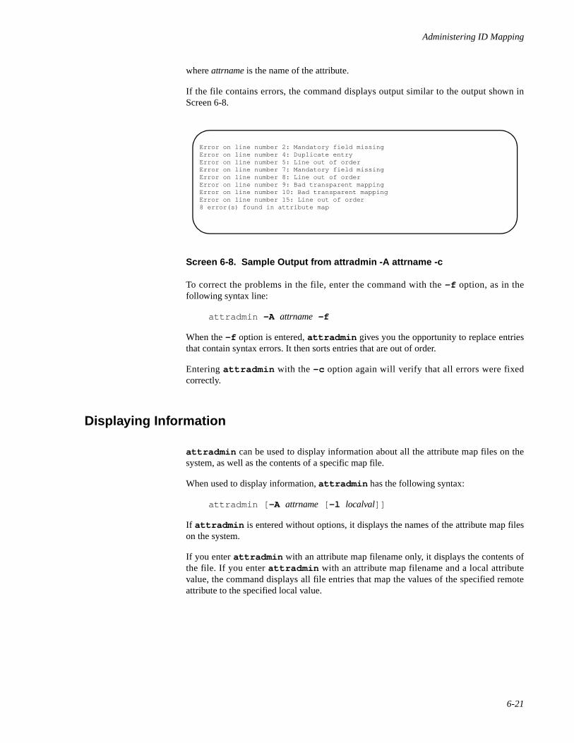
Administering ID Mapping
6-21
where attrname is the name of the attribute.
If the file contains errors, the command displays output similar to the output shown inScreen 6-8.
Screen 6-8. Sample Output from attradmin -A attrname -c
To correct the problems in the file, enter the command with the -f option, as in thefollowing syntax line:
attradmin -A attrname -f
When the -f option is entered, attradmin gives you the opportunity to replace entriesthat contain syntax errors. It then sorts entries that are out of order.
Entering attradmin with the -c option again will verify that all errors were fixedcorrectly.
Displaying Information 6
attradmin can be used to display information about all the attribute map files on thesystem, as well as the contents of a specific map file.
When used to display information, attradmin has the following syntax:
attradmin [ -A attrname [ -l localval]]
If attradmin is entered without options, it displays the names of the attribute map fileson the system.
If you enter attradmin with an attribute map filename only, it displays the contents ofthe file. If you enter attradmin with an attribute map filename and a local attributevalue, the command displays all file entries that map the values of the specified remoteattribute to the specified local value.
Error on line number 2: Mandatory field missingError on line number 4: Duplicate entryError on line number 5: Line out of orderError on line number 7: Mandatory field missingError on line number 8: Line out of orderError on line number 9: Bad transparent mappingError on line number 10: Bad transparent mappingError on line number 15: Line out of order8 error(s) found in attribute map
Network Administration
6-22
Setting Up a LID Map on a System Running the ES Utilities 6
For network communication to be possible in an environment in which the EnhancedSecurity (ES) Utilities are installed and running, both sides of the network connectionmust have the same security level. To ensure this, LIDs on a remote machine must bemapped, through an attribute map file, to their equivalents on the server. When a clientmakes a connection request, the server receives the LID of the remote process with therequest. The authentication scheme then calls the attrmap function, which uses a LIDmap file to map the remote LID to the equivalent local LID.
To set up networking on an ES server that uses the cr1 authentication scheme, the systemadministrator must create an attribute map file called RLID.map that maps remote LIDs.If the map file does not exist on the ES server, all incoming connection requests fail.
NOTE
In an Enhanced Security environment, the client administratorneeds to create a map as wel l . The cl ient map, cal ledLIDAUTH.map, is a variation of an attribute map that authorizesan outgoing connection request on a client on which the EnhancedSecurity Utilities are installed. When the client user attempts tomake a connection to a server, the Connection Server on the clientuses the map to determine if the connection can be made at theprocess's security level. Because the Connection Server uses themap and dictates its format, instructions for sett ing upLIDAUTH.map appear in the section called “Administering theConnection Server”.
At this time, cr1 is the only authentication scheme provided—with the exception of thetraditional login/password scheme, which doesn't rely on ID Mapping. This sectionexplains how to set up the LID mapping file required by cr1 specifically.
Setting Up RLID.map 6
To enable basic network communication on a server on which the Enhanced SecurityUtilities are installed and running, you must set up an attribute map that maps remoteLIDs. Because the names of map files are hard-coded in an authentication scheme, thescheme dictates the name of the map file. The LID mapping file used by cr1 must have thepathname /etc/idmap/attrmap/RLID.map.
NOTE
If the Least Privilege Module (LPM) is running, the ID Mappingadministrator must be in the NET role and be a member of groupsys. LPM is part of the Enhanced Security Utilities.
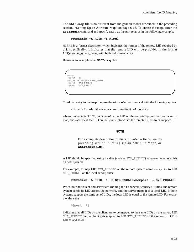
Administering ID Mapping
6-23
The RLID.map file is no different from the general model described in the precedingsection, “Setting Up an Attribute Map” on page 6-18. To create the map, enter theattradmin command and specify RLID as the attrname, as in the following example:
attradmin -A RLID -I M1@M2
M1@M2 is a format descriptor, which indicates the format of the remote LID required bycr1; specifically, it indicates that the remote LID will be provided in the formatLID@remote_system_name, with both fields mandatory.
Below is an example of an RLID.map file:
To add an entry to the map file, use the attradmin command with the following syntax:
attradmin -A attrname -a -r remoteval -l localval
where attrname is RLID, remoteval is the LID on the remote system that you want tomap, and localval is the LID on the server into which the remote LID is to be mapped.
NOTE
For a complete description of the attradmin fields, see thepreceding sect ion, “Set t ing Up an Attr ibute Map”, orattradmin(1M).
A LID should be specified using its alias (such as SYS_PUBLIC) whenever an alias existson both systems.
For example, to map LID SYS_PUBLIC on the remote system name memphis to LIDSYS_PUBLIC on the local server, enter
attradmin -A RLID -a -r SYS_PUBLIC@memphis -l SYS_PUBLIC
When both the client and server are running the Enhanced Security Utilities, the remotesystem sends its LID across the network, and the server maps it to a local LID. If bothsystems support the same set of LIDs, the local LID is equal to the remote LID. For exam-ple, the entry
*@sysA %1
indicates that all LIDs on the client are to be mapped to the same LIDs on the server. LIDSYS_PUBLIC on the client gets mapped to LID SYS_PUBLIC on the server, LID X toLID X, and so on.
M1@M2*@sysA %1SYS_PRIVATE@sysB USER_LOGIN*@sysB SYS_PUBLIC*@sysC SYS_PUBLIC
Network Administration
6-24
NOTE
The * is a special character that indicates, in this case, all LIDs onthe system. %1 is a field specifier that is used to set up transparentmapping; it indicates that remote LIDs should map to the samevalues on the server as specified in remote_attr.
For more information about the use of special characters and fieldspecifiers, see the preceding section, “Setting Up an AttributeMap” on page 6-18.
If both client and server do not support the same LIDs, then LIDs must be indicatedexplicitly in the map entry. For example, assume the client system, sysB , has defined asecurity level called private:sales, which has been assigned LID 10. Assume alsothat the server has an equivalent security level defined, but it has been assigned a local LIDof 12. In order for the client and server to communicate at the same security level, LID 10must be mapped to LID 12 on the server. The following command creates an entry thatmaps LID 10 on sysB to LID 12 on the server:
attradmin -A RLID -a -r LID10@sysB -l LID12
NOTE
There is no utility available to verify which LIDs representequivalent security levels on client and server. If you know thatthe client and server do not support identical LID assignments,meet with the administrator of the client machine to determinehow LIDs map before you enable communication between thetwo systems.
If you want to allow communication with a client that is not running the EnhancedSecurity Utilities, you can leave the remote LID in remote_attr blank. If the LID is blank,the server accepts a connection request without a remote LID and assigns the remoteprocess the specified local LID. The following command creates an entry that maps allrequests without LIDS from sysD to LID SYS_PUBLIC on the server:
attradmin -A RLID -a -r “@sysD” -l SYS_PUBLIC
attradmin will accept a blank LID even though the field M1 is mandatory. However, itdoes insist that the M1 field delimiter, @, be present.
Examples 6
If you do not know what levels and LIDs are supported on the client machine, you maywant to allow the client to communicate with your system only at SYS_PUBLIC, the low-est security level. The following command creates an entry that maps all LIDs on theremote system sysC to LID SYS_PUBLIC on the server:
attradmin -A RLID -a -r “*@sysC” -l SYS_PUBLIC

Administering ID Mapping
6-25
NOTE
To protect characters that are meaningful to the shell, enclose theremote_attr in quotes.
If you know that all clients on the network are secure and support the same levels and LIDassignments, you can set up transparent LID mapping with all remote systems by creatingan RLID.map file with the following single entry:
*@* %1
To create the entry, enter
attradmin -A RLID -a -r “*@*” -l %1
However, the network will probably include systems that do not support the EnhancedSecurity Utilities; it may be desirable to allow communication with those systems at thelowest security level. To create a file entry that allows all non-ES machines on the networkto connect to the server at the lowest security level, enter the following command:
attradmin -A RLID -a -r “@*” -l SYS_PUBLIC

Network Administration
6-26
7Administering the Basic Networking Utilities
Introduction to Basic Networking Utilities Administration . . . . . . . . . . . . . . . . . . . 7-1Overview of BNU . . . . . . . . . . . . . . . . . . . . . . . . . . . . . . . . . . . . . . . . . . . . . . . . . . . 7-2
What BNU Does. . . . . . . . . . . . . . . . . . . . . . . . . . . . . . . . . . . . . . . . . . . . . . . . . 7-2BNU Components . . . . . . . . . . . . . . . . . . . . . . . . . . . . . . . . . . . . . . . . . . . . . . . 7-4
Networking Hardware . . . . . . . . . . . . . . . . . . . . . . . . . . . . . . . . . . . . . . . . . 7-4Networking Programs . . . . . . . . . . . . . . . . . . . . . . . . . . . . . . . . . . . . . . . . . 7-4
User Programs . . . . . . . . . . . . . . . . . . . . . . . . . . . . . . . . . . . . . . . . . . . 7-4Administrative Programs . . . . . . . . . . . . . . . . . . . . . . . . . . . . . . . . . . . 7-5Networking Daemons . . . . . . . . . . . . . . . . . . . . . . . . . . . . . . . . . . . . . 7-6The remote.unknown File . . . . . . . . . . . . . . . . . . . . . . . . . . . . . . . . . . 7-6
Networking Support Files . . . . . . . . . . . . . . . . . . . . . . . . . . . . . . . . . . . . . . 7-7BNU Administration . . . . . . . . . . . . . . . . . . . . . . . . . . . . . . . . . . . . . . . . . . . . . 7-8
Database Support Files . . . . . . . . . . . . . . . . . . . . . . . . . . . . . . . . . . . . . . . . . . . . . . . 7-9The Permissions File . . . . . . . . . . . . . . . . . . . . . . . . . . . . . . . . . . . . . . . . . . . . . 7-10
Options . . . . . . . . . . . . . . . . . . . . . . . . . . . . . . . . . . . . . . . . . . . . . . . . . . . . 7-11The Devconfig File . . . . . . . . . . . . . . . . . . . . . . . . . . . . . . . . . . . . . . . . . . . . . . . 7-18The Sysfiles File . . . . . . . . . . . . . . . . . . . . . . . . . . . . . . . . . . . . . . . . . . . . . . . . . 7-19The Limits File . . . . . . . . . . . . . . . . . . . . . . . . . . . . . . . . . . . . . . . . . . . . . . . . . . 7-19The RLID.map File . . . . . . . . . . . . . . . . . . . . . . . . . . . . . . . . . . . . . . . . . . . . . . 7-20The LIDAUTH.map File . . . . . . . . . . . . . . . . . . . . . . . . . . . . . . . . . . . . . . . . . . 7-20The Config File. . . . . . . . . . . . . . . . . . . . . . . . . . . . . . . . . . . . . . . . . . . . . . . . . . 7-21The Devices File. . . . . . . . . . . . . . . . . . . . . . . . . . . . . . . . . . . . . . . . . . . . . . . . . 7-22
Protocols . . . . . . . . . . . . . . . . . . . . . . . . . . . . . . . . . . . . . . . . . . . . . . . . . . . 7-27Serial cu Connections and the Devices File . . . . . . . . . . . . . . . . . . . . . . . . 7-28TCP/IP cu Connections and the Devices File . . . . . . . . . . . . . . . . . . . . . . . 7-28
The Dialers File . . . . . . . . . . . . . . . . . . . . . . . . . . . . . . . . . . . . . . . . . . . . . . . . . 7-29The Systems File . . . . . . . . . . . . . . . . . . . . . . . . . . . . . . . . . . . . . . . . . . . . . . . . 7-31
Serial cu Connections and the Systems File . . . . . . . . . . . . . . . . . . . . . . . . 7-37TCP/IP cu Connections and the Systems File. . . . . . . . . . . . . . . . . . . . . . . 7-38
The Dialcodes File . . . . . . . . . . . . . . . . . . . . . . . . . . . . . . . . . . . . . . . . . . . . . . . 7-38The Poll File . . . . . . . . . . . . . . . . . . . . . . . . . . . . . . . . . . . . . . . . . . . . . . . . . . . . 7-39The Grades File . . . . . . . . . . . . . . . . . . . . . . . . . . . . . . . . . . . . . . . . . . . . . . . . . 7-39
Default Grade . . . . . . . . . . . . . . . . . . . . . . . . . . . . . . . . . . . . . . . . . . . . . . . 7-41Administrative Support Files . . . . . . . . . . . . . . . . . . . . . . . . . . . . . . . . . . . . . . . . . . . 7-41Log Files . . . . . . . . . . . . . . . . . . . . . . . . . . . . . . . . . . . . . . . . . . . . . . . . . . . . . . . . . . 7-43
Command Log . . . . . . . . . . . . . . . . . . . . . . . . . . . . . . . . . . . . . . . . . . . . . . . . . . 7-44System History Log . . . . . . . . . . . . . . . . . . . . . . . . . . . . . . . . . . . . . . . . . . . . . . 7-45Error Log . . . . . . . . . . . . . . . . . . . . . . . . . . . . . . . . . . . . . . . . . . . . . . . . . . . . . . 7-46Transfer Log . . . . . . . . . . . . . . . . . . . . . . . . . . . . . . . . . . . . . . . . . . . . . . . . . . . . 7-47
Report Statistics of File Transfer. . . . . . . . . . . . . . . . . . . . . . . . . . . . . . . . . 7-48Accounting Log . . . . . . . . . . . . . . . . . . . . . . . . . . . . . . . . . . . . . . . . . . . . . . . . . 7-49Security Log . . . . . . . . . . . . . . . . . . . . . . . . . . . . . . . . . . . . . . . . . . . . . . . . . . . . 7-50
File Transfer (xfer) Security Log . . . . . . . . . . . . . . . . . . . . . . . . . . . . . . . . 7-50Remote Execution (rexe) Security Log . . . . . . . . . . . . . . . . . . . . . . . . . . . . 7-51
Performance Log . . . . . . . . . . . . . . . . . . . . . . . . . . . . . . . . . . . . . . . . . . . . . . . . 7-52Connection (conn) Performance Log . . . . . . . . . . . . . . . . . . . . . . . . . . . . . 7-53File Transfer (xfer) Performance Log . . . . . . . . . . . . . . . . . . . . . . . . . . . . . 7-54

Network Administration
Foreign Log. . . . . . . . . . . . . . . . . . . . . . . . . . . . . . . . . . . . . . . . . . . . . . . . . . . . . 7-56Adding uucp Logins. . . . . . . . . . . . . . . . . . . . . . . . . . . . . . . . . . . . . . . . . . . . . . . . . . 7-56BNU Setup Procedures . . . . . . . . . . . . . . . . . . . . . . . . . . . . . . . . . . . . . . . . . . . . . . . 7-57
(1) For All Types of Connection . . . . . . . . . . . . . . . . . . . . . . . . . . . . . . . . . . . . . 7-57(2a) For Connections Using the New CS Dialer Type - the Client Machine . . . 7-58
Essential Steps . . . . . . . . . . . . . . . . . . . . . . . . . . . . . . . . . . . . . . . . . . . . . . . 7-58Optional or Conditional Steps . . . . . . . . . . . . . . . . . . . . . . . . . . . . . . . . . . . 7-58
(2b) For Connections Using the New CS Dialer Type - the Server Machine . . . 7-59Essential Steps . . . . . . . . . . . . . . . . . . . . . . . . . . . . . . . . . . . . . . . . . . . . . . . 7-59Optional or Conditional Steps . . . . . . . . . . . . . . . . . . . . . . . . . . . . . . . . . . . 7-60
(3a) For Connections Not Using the CS Dialer Type- the Client Machine . . . . 7-61Optional or Conditional Steps . . . . . . . . . . . . . . . . . . . . . . . . . . . . . . . . . . . 7-61
(3b) For Connections Not Using the CS Dialer Type - the Server Machine. . . . 7-62Optional or Conditional Steps . . . . . . . . . . . . . . . . . . . . . . . . . . . . . . . . . . . 7-62
BNU Maintenance . . . . . . . . . . . . . . . . . . . . . . . . . . . . . . . . . . . . . . . . . . . . . . . . . . . 7-63Automated Networking Maintenance (cron) . . . . . . . . . . . . . . . . . . . . . . . . . . . 7-63
uudemon.poll . . . . . . . . . . . . . . . . . . . . . . . . . . . . . . . . . . . . . . . . . . . . . . . . 7-63uudemon.hour . . . . . . . . . . . . . . . . . . . . . . . . . . . . . . . . . . . . . . . . . . . . . . . 7-64uudemon.admin . . . . . . . . . . . . . . . . . . . . . . . . . . . . . . . . . . . . . . . . . . . . . . 7-64uudemon.clean. . . . . . . . . . . . . . . . . . . . . . . . . . . . . . . . . . . . . . . . . . . . . . . 7-65
Manual Maintenance. . . . . . . . . . . . . . . . . . . . . . . . . . . . . . . . . . . . . . . . . . . . . . 7-65Cleaning Up Log Files. . . . . . . . . . . . . . . . . . . . . . . . . . . . . . . . . . . . . . . . . 7-65
BNU Debugging. . . . . . . . . . . . . . . . . . . . . . . . . . . . . . . . . . . . . . . . . . . . . . . . . . . . . 7-66Check Basic Information . . . . . . . . . . . . . . . . . . . . . . . . . . . . . . . . . . . . . . . . . . 7-67Check for Faulty ACU/Modem. . . . . . . . . . . . . . . . . . . . . . . . . . . . . . . . . . . . . . 7-67Check Systems File. . . . . . . . . . . . . . . . . . . . . . . . . . . . . . . . . . . . . . . . . . . . . . . 7-67Debug Transmissions . . . . . . . . . . . . . . . . . . . . . . . . . . . . . . . . . . . . . . . . . . . . . 7-67
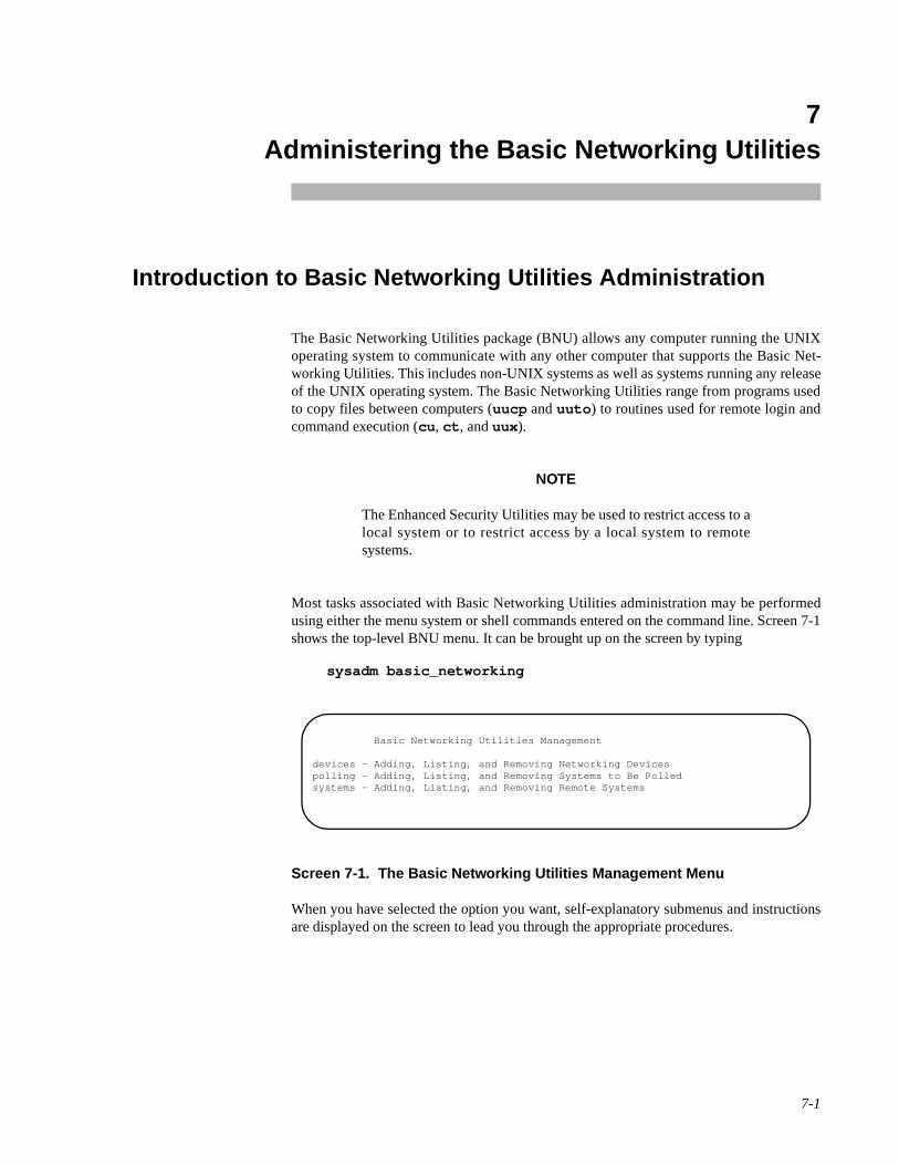
7-1
7Chapter 7Administering the Basic Networking Utilities
777
Introduction to Basic Networking Utilities Administration 7
The Basic Networking Utilities package (BNU) allows any computer running the UNIXoperating system to communicate with any other computer that supports the Basic Net-working Utilities. This includes non-UNIX systems as well as systems running any releaseof the UNIX operating system. The Basic Networking Utilities range from programs usedto copy files between computers (uucp and uuto ) to routines used for remote login andcommand execution (cu , ct , and uux ).
NOTE
The Enhanced Security Utilities may be used to restrict access to alocal system or to restrict access by a local system to remotesystems.
Most tasks associated with Basic Networking Utilities administration may be performedusing either the menu system or shell commands entered on the command line. Screen 7-1shows the top-level BNU menu. It can be brought up on the screen by typing
sysadm basic_networking
Screen 7-1. The Basic Networking Utilities Management Menu
When you have selected the option you want, self-explanatory submenus and instructionsare displayed on the screen to lead you through the appropriate procedures.
Basic Networking Utilities Management
devices - Adding, Listing, and Removing Networking Devicespolling - Adding, Listing, and Removing Systems to Be Polledsystems - Adding, Listing, and Removing Remote Systems
Network Administration
7-2
Overview of BNU 7
What BNU Does 7
The following is a general description of the BNU process. The component parts of thisprocess are described either later in this chapter or in the places indicated. The phases aremarked on the diagram that follows.
Phase A A user on the local machine issues a command requesting filetransfer or remote execution communication with a remotecomputer (phase A). Several BNU database support files are readto determine if the remote computer is accessible by the localcomputer and the priority of the user's request compared to otherusers' requests. This phase ends by queuing the user's request in aspool area on the local machine and triggering the next phase.
Phase B The uucico routine is triggered automatically (phase B). It readsseveral BNU database support files to determine when the remotecomputer can be reached, how to establish the link to the remotecomputer, how to handle data flow between the local and remotecomputers, and the maximum number of simultaneous requestsfor communication to the remote computer.
Phase B' The uucico routine calls the connection routine, dial [seedial(3N) ], and passes the request and associated information tothe server.
Phases C and C' The uucico routine on the remote computer is triggeredautomatically when a call for communication is received from thelocal computer (phase C). In this phase, the remote uucicoroutine reads BNU database support files on its computer todetermine if the calling computer is allowed access, and whataction to take if the calling computer is not allowed access (phaseC'). For calling computers that are allowed access to the remotecomputer, the level of access is determined in this phase.
Phase D Requests initiated on the local computer may contain commandsto be executed on the remote computer (phase D). When thesecommands arrive on the remote computer, they are stored in aspool area. During this phase, the remote uuxqt routine runsthese commands on the remote computer.
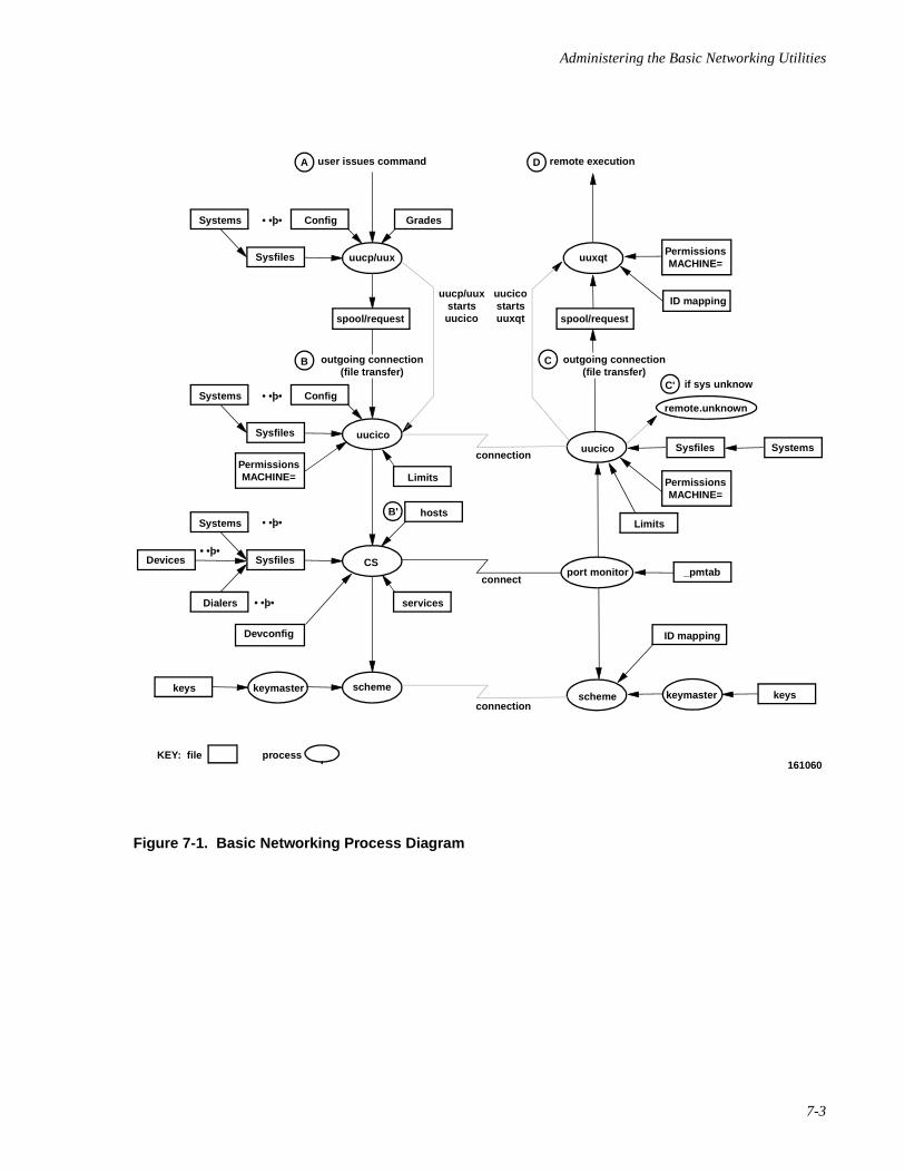
Administering the Basic Networking Utilities
7-3
Figure 7-1. Basic Networking Process Diagram
161060
Systems
Sysfiles
spool/request spool/request
ID mapping
uucp/uux
uucp/uuxstartsuucico
uucicostartsuuxqt
user issues command
Config
A
Grades• •þ•
uuxqt
Systems
Sysfiles
PermissionsMACHINE=
PermissionsMACHINE=
PermissionsMACHINE=
CS
KEY: file process
Config
connection
connect
hosts
• •þ•
• •þ•
• •þ•
• •þ•
Sysfiles Systems
_pmtab
Devconfig
Systems
Dialers
SysfilesDevices
keys
ID mapping
Limits
services
Limits
schemekeymasterkeyskeymaster
uucicouucico
scheme
port monitor
remote.unknown
remote executionD
outgoing connection(file transfer)
B
B'
outgoing connection(file transfer)
C
if sys unknowC'
connection
Network Administration
7-4
BNU Components 7
Networking Hardware 7
Before a computer can communicate with other computers, hardware must be set up tocomplete the communications link. The hardware needed will depend on how you want toconnect the computers. Computers may be connected using
• direct links
• telephone lines
• local area networks
Hardware installation is not the subject of this chapter.
Networking Programs 7
BNU is made up of programs and support files. BNU programs include user programs,administrative programs, and daemons. These three types of BNU programs are describedin this section. They are described briefly with pointers to the manual pages that describethem in detail.
BNU support files are described in detail in the next section.
User Programs 7
The Basic Networking Utilities user programs are:
cu Calls another UNIX system, a terminal, or possibly a non-UNIXsystem and manages an interactive conversation with possibletransfers of files. See cu(1C) for more information.
ct Dials the telephone number of a modem that is attached to aterminal and spawns a login process to that terminal. See ct(1C)for more information.
uucp Copies files from a local UNIX machine to a destination either onthe same machine or on a remote UNIX machine. uucp may alsobe used to copy files from a remote computer to another remotecomputer, to copy files from one location to another on a givenremote computer, and to copy files from a remote computer to alocal computer. Some remote copies will be restricted by theadministrator of the remote machine. See uucp(1C) for moreinformation.
uuto Uses the uucp facility to send files to PUBDIR on anothersystem. See uuto(1C) for more information.
uupick Accepts or rejects files transmitted to a user. Specifically, uupicksearches PUBDIR for files destined for the user. uupick isdescribed on uuto(1C) .
Administering the Basic Networking Utilities
7-5
uux Gathers files from various systems, executes a command on anamed system and then sends the output to a file on anothernamed system. See uux(1C) for more information.
uustat Displays the status of, or cancels, previously specified uucpcommands; provides remote system performance information;and provides remote status of uucp connections to other systems.See uustat(1C) for more information.
uulog Queries log files of uucp and uuxqt transactions. uuxqt is alsodescribed in “Networking Daemons” on page 7-6. uulog isdescribed on uucp(1C).
uuglist Prints the list of service grades available on a system for use withthe -g option of uucp and uux . See uuglist(1C) for moreinformation.
uuname Lists the names of systems known to uucp . uuname is describedon uucp(1C) .
uuencode Converts a binary file into an ASCII-encoded file that can betransmitted using mail [see mail(1) ]. See uuencode(1C)for more information.
uudecode Reads an encoded file, strips off any leading and trailing linesadded by mailer programs, and recreates the original binary data.See uuencode(1C) for more information.
The BNU user programs are located in /usr/bin . The BNU user programs aredescribed in their respective manual pages. No special permissions are needed to use theseprograms.
Administrative Programs 7
The Basic Networking Utilities include the following three administrative programs:
uucheck Checks for the presence of the uucp system-required files andd i rec to r ies . uucheck a l so checks the/e tc /uucp/Permiss ions f i l e fo r e r ro rs . Seeuucheck(1M) for more information.
uucleanup Scans the spool directories for old files and removes them. Thedefault values for file aging can be changed by command lineoptions. An option also exists to restrict uucleanup 's action tothe system spool directory. See uucleanup(1M) for moreinformation.
Uutry Uutry is a shell used to invoke uucico when calling a remotesite. Debugging is initially turned on and the debugging output isput in a file. See Uutry(1M) for more information.
The BNU administrative programs are in /usr/lib/uucp , along with BasicNetworking shell scripts. All Basic Networking Utilities administrative commands arefully described in their respective manual pages.
Network Administration
7-6
Since uucp owns the Basic Networking and spooled data files, the uucp login ID shouldbe used only for BNU administration. The home directory for the uucp login is/usr/lib/uucp . Another Basic Networking login ID, nuucp, is used by remotecomputers to access the local machine. Calls to nuucp are answered by uucico.
Networking Daemons 7
The Basic Networking Utilities package includes three daemons. A daemon is a standingserver or a routine that runs as a background process and performs system-wide publicfunctions. The BNU daemons handle both file transfers and command execution. Theymay be invoked from the shell.
uucico Checks permissions, transfers files (if requested), logs results, and notifies theuser (by mail ) of transfer completion. When the local uucico daemon callsa remote computer, it invokes the dial routine [see dial(3N) ], which thenobtains authenticated connections from the Connection Server.
The Connection Server sets the security levels of all connections it establishes.
NOTE
Only files of the same security level can be transferred by any oneuucico.
uucico is executed by the uucp , uuto , and uux programs, after all therequired files have been created, to contact the remote computer. It is alsoexecuted by uusched and Uutry . See uucico(1M) for more information.
uuxqt Executes remote execution requests. uuxqt searches the spool directory forexecute files (always named X.file ) that have been sent from a remotecomputer. When an execute file is found, uuxqt opens it to get the list of datafiles required for the execution. It then checks to see if the required data filesare available and accessible. If the files are present and can be accessed,uuxqt checks the Permissions file to verify that it has permission toexecute the requested command. uuxqt is executed by the uudemon.hourshell script, which is started by cron . See uuxqt(1M) for moreinformation.
uusched Schedules the queued work in the spool directory. Before starting uucico ,uusched randomizes the order in which remote computers will be called.uusched is executed by the shell script uudemon.hour , which is started bycron . See uusched(1M) for more information.
The remote.unknown File 7
The remote.unknown file is a binary program that executes when a machine not foundin any of the Systems files starts a conversation. It will log the conversation attempt anddrop the connection. Its function is similar to that of a daemon.
Administering the Basic Networking Utilities
7-7
CAUTION
If you change the permissions of the remote.unknown file so itcannot execute, your system will accept connections from anysystem.
Networking Support Files 7
There are three types of BNU support files: database files, administrative files, and logfiles.
• Database Files BNU database files are located in /etc/uucp . They areresponsible for much of the actual networking activity associated with theBasic Networking Utilities package. In general, they determine whichcomputers your computer will communicate with, the devices over whichthe communication will take place, the protocols for communicating withremote computers, and the security level access.
NOTE
BNU database support files used with previous releases of theUNIX operating system are compatible with the current releaseand may be used without alteration.
The following list describes each of the database support files and itsfunction briefly. These files are described in detail in the “Database Sup-port Files” on page 7-9.
Config Contains a list of variable parameters within BNU. Theadministrator can set these parameters to configure the net-work manually.
Devconfig This file is used to configure network connections onTCP/IP or some other network provider.
Devices Contains information concerning the location and line speedof automatic call units, direct links, and network devices.
Dialcodes Contains dial-code abbreviations that may be used in thetelephone number field of the Systems and Dialers files.
Dialers Contains character strings required to communicate withnetwork devices, automatic calling units, and direct links.
Grades Used to define the job grades, and the permissionsassociated with each job grade, that users may specify toqueue jobs to a remote computer.
Limits Defines the maximum number of simultaneous uucico s,uuxqt s, and uusched s permitted on a machine.
Network Administration
7-8
Permissions Defines the levels of access granted to remote computerswhen they attempt to transfer files or execute remotecommands on the local computer.
Poll Defines computers that are to be polled by the local systemand when they are polled.
Sysfiles Assigns different or multiple files to be used as Systems ,Devices , and Dialers files by various services (such asuucico and cu ).
Systems Contains information needed by the uucico daemon andthe cu program to establish a link to a remote system suchas the name of the remote system, the name of the connect-ing device associated with the remote system, when thesystem can be reached, a telephone number or networkaddress, login ID, and password.
The Systems file is also used by the client machine toverify that the client is allowed to connect to the server andby the server machine to verify that the server may acceptcalls from the client.
RLID.map Contains the remote system name and incoming LID asinput values and the local LID as an output value. When arequest for access is initiated from a remote system, theauthentication scheme checks this file and matches theincoming LID, then assigns the local LID to the request as alocal level. This then determines what the requester canaccess. RLID.map is described in detail in Chapter 6,“Administering ID Mapping.”
LIDAUTH.map The LIDAUTH.map file is consulted by the ConnectionServer to determine whether the local system is allowed toinitiate a connection to a remote system at the current LID.The file contains the remote system name and local LID asinput values and %1 or %i as the output value to showwhether the local LID is authorized or invalid.
• Administrative Files BNU administrative files are created in spooldirectories by network processes to hold temporary data or storeinformation about remote transfers and command executions. They aredescribed in detail in “Administrative Support Files” on page 7-41.
• Log Files BNU log files keep track of overall statistics for the computernetwork, particularly in the areas of security and accounting. The structureof each of the BNU log files is described in “Log Files” on page 7-43.
BNU Administration 7
This section outlines the steps a system administrator must take before using the BasicNetworking Utilities and indicates where to find the information required to administerBNU once it has been set up.
Administering the Basic Networking Utilities
7-9
NOTE
BNU database support files used with previous releases of theUNIX operating system are compatible with the current releaseand may be used without alteration.
Briefly, BNU administration involves the following procedures:
Setup BNU setup is described in detail in the “Database Support Files”on page 7-9.
Maintenance Basic Networking Utilities maintenance involves updating BNUdatabase support files when necessary, tracking BNU transactions,and cleaning up BNU administrative and log files. BNUMaintenance is discussed in “BNU Maintenance” on page 7-63.
Debugging BNU debugging procedures help identify and correct commonproblems in BNU operation and administration. BNU debuggingprocedures are discussed in “BNU Debugging” on page 7-66.
Database Support Files 7
Setting up the Basic Networking Utilities involves configuring the database support files.This section describes these files and their structure in detail. Some of the databasesupport files are delivered with the system. In some cases these default files can be usedwithout modification. In other cases they cannot. Each of the file descriptions belowindicates whether the default file may be used and, if not, what changes must be made.BNU support files are in the /etc/uucp directory. The RLID.map and LIDAUTH.mapfiles are in the /etc/idmap/attrmap directory.
NOTE
BNU database support files used with previous releases of theUNIX operating system are compatible with the current releaseand may be used without alteration.
Wherever possible, changes to the database support files should be made by using thesystem administration menus (accessed through the sysadm command). The BNU setupprocedure provides the steps for initializing the BNU database files. This procedure usesthe sysadm subcommands and a text editor, except for the security-related database files/etc/idmap/attrmap/RLID.map and /etc/idmap/attrmap/LIDAUTH.map .To maintain these two files, use the attradmin command. The use of attradmin tomaintain RLID.map is described under Chapter 6, “Administering ID Mapping.” Its usein maintaining LIDAUTH.map is described in Chapter 4, “Administering the ConnectionServer.”
Begin by typing
Network Administration
7-10
sysadm basic_networking
This will give you the starting menu. From this point, you can begin setting up(initializing) the various database files. To get help along the way, press the HELP func-tion key. This will give you a detailed description of a menu selection. Pressing theCANCEL function key exits help mode.
Setting up the Permissions , Devconfig , Sysfiles and Limits files, and addinguucp logins are principal functions in the initial Basic Networking setup process.
The permissions on networking devices should be 0600, with the owner set to root .
The level of the BNU administrative files should be set to SYS_PUBLIC so that processesrunning at all levels will be able to read these files.
The Permissions File 7
A default /etc/uucp/Permissions file is delivered with the system and contains thefollowing entry, which provides maximum security:
LOGNAME=nuucp
/etc/uucp/Permissions specifies the permissions that remote computers have withrespect to login, file access, and command execution. There are options that restrict theremote computer's ability to request files and its ability to receive files queued by the localsite. Another option is available that specifies the commands that a remote site can executeon the local computer.
The following items should be considered when using the Permissions file to restrictthe level of access granted to remote computers:
• All login IDs used by remote computers to log in for uucpcommunications must appear in one and only one LOGNAME entry.
• Any site that is called whose name does not appear in a MACHINE entry,will have the following default permissions and restrictions:
- Local send and receive requests will be executed.
- The remote computer can send files to your computer's/var/spool/uucppublic directory.
- The commands sent by the remote computer for execution on yourcomputer must be one of the default commands; usually rmail .
• When a remote machine calls you, unless you have a unique login andpassword for that machine or are using cr1 authentication, you don't knowif the machine is who it says it is.
Each entry is a logical line. Physical lines may be terminated by a backslash (\) to indicatethat the entry continues on the next line. Entries are made up of options delimited by whitespace. Each option is a name/value pair in the following format:
name=value
Administering the Basic Networking Utilities
7-11
Note that no white space is allowed within an option assignment.
Comment lines begin with a pound sign (#) and they occupy the entire line up to a newlinecharacter. Blank lines are ignored (even within multi-line entries).
There are two types of Permissions file entries:
LOGNAME Specifies the permissions that take effect when a remote computerlogs in on (calls) your computer.
MACHINE Specifies permissions that take effect when your computer logs inon (calls) a remote computer.
Options 7
This section describes each option, specifies how they are used, and lists their defaultvalues.
REQUESTWhen a remote computer calls your computer and requests the transfer of afile, this request is granted or denied based on the value of the REQUESToption. The string
REQUEST=yes
specifies that the remote computer can request the transfer of files from yourcomputer. The string
REQUEST=no
specifies that the remote computer cannot request file transfers from yourcomputer. no is the default value. It will be used if the REQUEST option is notspecified. The REQUEST option can appear in either a LOGNAME (remote callsyou) entry or a MACHINE (you call remote) entry.
SENDFILESWhen a remote computer calls your computer and completes its work, it mayattempt to take work your computer has queued for it. The SENDFILESoption specifies whether your computer can send the work queued for theremote computer.
The string
SENDFILES=yes
specifies that your computer may send the work that is queued for the remotecomputer as long as it logged in as one of the names in the LOGNAME option.This string is mandatory if your computer is in a “passive mode” with respectto the remote computer.
The string
SENDFILES=call
specifies that files queued in your computer will be sent only when your com-puter calls the remote computer. The call value is the default for the
Network Administration
7-12
SENDFILES option. This option is only significant in LOGNAME entries, sinceMACHINE entries apply when calls are made out to remote computers. If theoption is used with a MACHINE entry, it will be ignored.
PUBDIR This option defines the directory that uucp will use for public file transfers.The default value is /var/spool/uucppublic , and this value is used toinitialize the value of the READ and WRITE options described below.
CAUTION
Changing this value is discouraged, as it may have an adverseaffect on other system utilities.
READ and WRITEThese options specify the various parts of the file system that uucico canread from or write to. The READ and WRITE options can be used with eitherMACHINE or LOGNAME entries.
The default for both the READ and WRITE options is the PUBDIR directory,which would be equivalent to the following entries:
READ=/var/spool/uucppublicWRITE=/var/spool/uucppublic
The strings
READ=/ WRITE=/
specify permission to access any file that can be accessed by a local userwhose access permissions are set to “other.”
The value of these entries is a colon separated list of pathnames. The READoption is for requesting files, and the WRITE option for depositing files. Oneof the values must be a component of any full pathname of a file coming in orgoing out. To grant permission to deposit files in /usr/news as well as thepublic directory, the following values would be used with the WRITE option:
WRITE=/var/spool/uucppublic:/usr/news
It should be pointed out that if the READ and WRITE options are used, allpathnames must be specified because the pathnames are not added to thedefault list. For instance, if the /usr/news pathname was the only onespecified in a WRITE option, permission to deposit files in the public directorywould be denied.
You should be careful what directories you make accessible for reading andwriting by remote systems. For example, you probably wouldn't want remotecomputers to be able to write over your /etc/passwd file, so /etcshouldn't be open to writes.
Administering the Basic Networking Utilities
7-13
NOREAD and NOWRITEThe NOREAD and NOWRITE options specify exceptions to the READ andWRITE options or defaults. The strings
READ=/ NOREAD=/etc WRITE=/var/spool/uucppublic
would permit reading any file except those in the /etc directory (and its sub-directories—remember, these are prefixes) and writing only to the default/var/spool/uucppublic directory. NOWRITE works in the same man-ner as the NOREAD option. The NOREAD and NOWRITE can be used in bothLOGNAME and MACHINE entries.
DIRECT This option specifies whether files that have been received can be placed into adirectory into the destination directory. If the value of DIRECT is no, files thatare received are put into uucp 's private spool directory, and then copied to thedestination directory. If the value of DIRECT is yes, files that are received aredirectly put into the destination directory. The default value for DIRECT is no.
CALLBACKThe CALLBACK option is used in LOGNAME entries to specify that notransaction will take place until the calling system is called back. CALLBACKcan be used in the following two examples. From a security standpoint, if youcall back a machine, you can be fairly certain it is the machine it says it is. Ifyou are doing long data transmissions, you can choose the machine that willbe billed for the longer call.
The string
CALLBACK=yes
specifies that your computer must call the remote computer back before anyfile transfers will take place.
The default for the CALLBACK option is
CALLBACK=no
The CALLBACK option is rarely used. Note that if two sites have this optionset for each other, a conversation will never get started and no transfers willoccur between them.
KEYS The KEYS= entry defines the key management facility that obtains keys usedin the authentication of remote command execution requests. This optionprovides an override capability for the global value specified in the Configfile. At present, cr1 is the only key management facility available to BNU.There is no default key management facility. To specify the cr1 keymanagement facility, the string
KEYS=cr1
must be entered in the Permissions file.
CRYPT This option specifies the encryption type to use when authenticating remoteexecution requests generated by the uux command. The default value is des .The value enigma may be used if the export controlled Encryption Utilities
Network Administration
7-14
Package is not available. This option provides an override capability for theglobal value specified in the Config file.
AUTH The AUTH= entry determines whether authentication is required for remoterequests. This option provides an override capability for the global valuespecified in the Config file. If either of the strings
AUTH=yes
or
AUTH=req
is included in the Permissions file, no remote command request will beaccepted without authentication. When authenticated requests are executed,they are executed under the mapped id of the originator and all commands areallowed, that is, the COMMANDS value is ignored.
Either of the strings
AUTH=opt
or
AUTH=no
indicates that authentication is not required for remote command execution. Inthis case, commands are executed as in previous releases, limited by theCOMMANDS value.
NOTE
If authentication is attempted but fails, the request will berejected, regardless of the value of AUTH.
COMMANDS
CAUTION
The COMMANDS option can compromise the security of yoursystem. Use it with extreme care.
The COMMANDS option is used only for unauthenticated remotecommand execution requests. See KEYS and AUTH, above, for usewith authenticated remote command execution requests.
The uux program will generate remote execution requests and queue them tobe transferred to the remote computer. Files and a command are sent to thetarget computer for remote execution. The COMMANDS option can be used inMACHINE entries to specify the commands that a remote computer canexecute on the local computer. Note that COMMANDS is not relevant in a
Administering the Basic Networking Utilities
7-15
LOGNAME entry; COMMANDS in MACHINE entries define command permis-sions whether we call the remote system or it calls us.
The string
COMMANDS=rmail
specifies the default commands that a remote computer can execute on yourcomputer. If a command string is used in a MACHINE entry, the default com-mands are overridden. For instance, the entry
MACHINE=owl:raven:hawk:dove \COMMANDS=rmail:rnews:lp
overrides the COMMANDS default so that the computers owl , raven , hawk,and dove can now execute rmail , rnews , and lp on your computer.
In addition to the names as specified above, there can be full path names ofcommands. For example,
COMMANDS=rmail:/usr/lbin/rnews:/usr/local/lp
specifies that the command rmail uses the default path. The default path forremote execution is /usr/bin. When the remote computer specifies rnewsor /us r / lb in / rnews f o r the command to be execu ted ,/usr/lbin/rnews will be executed regardless of the default path. Like-wise, /usr/local/lp is the lp command that will be executed.
CAUTION
Including the ALL value in the list means that any command fromthe remote computer(s) specified in the entry will be executed. Ifyou use this value, you give the remote computer full access toyour computer. Be careful. This allows far more access than nor-mal users have.
The string
COMMANDS=/usr/lbin/rnews:ALL:/usr/local/lp
illustrates two points:
• The ALL value can appear anywhere in the string.
• The pathnames specified for rnews and lp will be used(instead of the default) if the requested command does not con-tain the full pathnames for rnews or lp.
If commands are executed using the authenticated remote execution feature,the COMMANDS list is ignored and all commands are available to theauthenticated user, as if the user had logged in directly.
The VALIDATE option described below should be used with the COMMANDSoption whenever potentially dangerous commands like cat and uucp are
Network Administration
7-16
specified with the COMMANDS option. Any command that reads or writes filesis potentially dangerous to local security when executed by the uucp remoteexecution daemon (uuxqt ).
VALIDATEThe VALIDATE option is used in conjunction with the COMMANDS optionwhen specifying commands that are potentially dangerous to your computer'ssecurity. It is used to provide a certain degree of verification of the caller'sidentity. The use of the VALIDATE option requires that privileged computershave a unique login/password for uucp transactions. An important aspect ofthis validation is that the login/password associated with this entry be pro-tected. If an outsider gets that information, that particular VALIDATE optioncan no longer be considered secure. VALIDATE is merely an added level ofsecurity on top of th COMMANDS option (though it is a more secure way toopen command access than ALL).
Careful consideration should be given to providing a remote computer with aprivileged login and password for uucp transactions. Giving a remotecomputer a special login and password with file access and remote executioncapability is like giving anyone on that computer a normal login and passwordon your computer. Therefore, if you cannot trust users on the remotecomputer, do not provide that computer with a privileged login and password.
The LOGNAME entry
LOGNAME=uucpfriend VALIDATE=eagle:owl:hawk
specifies that if one of the remote computers that claims to be eagle, owl, orhawk logs in on your computer, it must have used the login uucpfriend. Ifan outsider gets the uucpfriend login/password, masquerading is trivial.
But what does this have to do with the COMMANDS option, which only appearsin MACHINE entries? It links the MACHINE entry (and COMMANDS option)with a LOGNAME entry associated with a privileged login. This link is neededbecause the execution daemon is not running while the remote computer islogged in. In fact, it is an asynchronous process with no knowledge of whatcomputer sent the execution request. Therefore, the real question is: How doesyour computer know where the execution files came from?
Each remote computer has its own “spool” directory on your computer. Thesespool directories have write permission given only to the UUCP family ofprograms. The execution files from the remote computer are put in its spooldirectory after being transferred to your computer. When the uuxqt daemonruns, it can use the spool directory name to find the MACHINE entry in thePermissions file and get the COMMANDS list, or a default list will be used ifthe computer name does not appear in the Permissions file.
The following example shows the relationship between the MACHINE andLOGNAME entries:
MACHINE=eagle:owl:hawk REQUEST=yes \COMMANDS=rmail:/usr/lbin/rnews \READ=/ WRITE=/
Administering the Basic Networking Utilities
7-17
LOGNAME=uucpz VALIDATE=eagle:owl:hawk \REQUEST=yes SENDFILES=yes \READ=/ WRITE=/
The value in the COMMANDS opt ion means that remote mai l and/usr/lbin/rnews can be executed by remote users.
In the first entry, you must make the assumption that when you want to callone of the computers listed, you are really calling either eagle , owl , orhawk. Therefore, any file put into one of the eagle , owl , or hawk spooldirectories is put there by one of those computers. If a remote computer logsin and says that it is one of these three computers, its execution files will alsobe put in the privileged spool directory. You therefore have to validate that thecomputer has the privileged login uucpz .
MACHINE Entry for “Other” SystemsYou may want to specify different option values for the computers yourcomputer calls that are not mentioned in specific MACHINE entries. This mayoccur when there are many computers calling in and the command set changesfrom time to time. The name OTHER for the computer name is used for thisentry as shown below:
MACHINE=OTHER \COMMANDS=rmail:rnews:/usr/lbin/Photo:/usr/lbin/xp
All other options available for the MACHINE entry may also be set for thecomputers that are not mentioned in other MACHINE entries.
Combining MACHINE and LOGNAME EntriesIt is possible to combine MACHINE and LOGNAME entries into a single entrywhere the common options are the same. For example, the two entries
MACHINE=eagle:owl:hawk REQUEST=yes \ READ=/ WRITE=/
and
LOGNAME=uucpz REQUEST=yes SENDFILES=yes \ READ=/ WRITE=/
share the same REQUEST, READ, and WRITE options. These two entries canbe merged as shown below:
MACHINE=eagle:owl:hawk REQUEST=yes \LOGNAME=uucpz SENDFILES=yes \ READ=/ WRITE=/
As can be seen, the default entry
LOGNAME=nuucp
provides maximum security since it is equivalent to
LOGNAME=nuucp \MACHINE=OTHER \REQUEST=no \
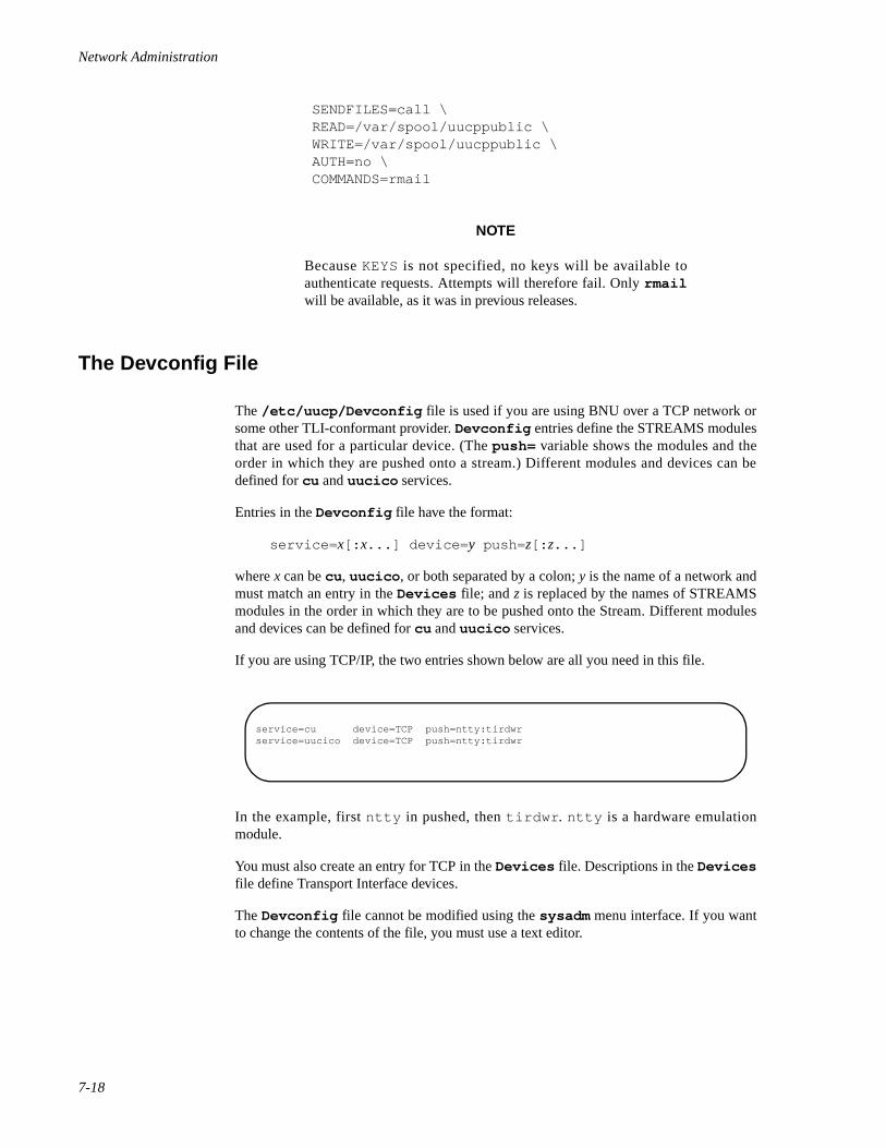
Network Administration
7-18
SENDFILES=call \READ=/var/spool/uucppublic \WRITE=/var/spool/uucppublic \AUTH=no \COMMANDS=rmail
NOTE
Because KEYS is not specified, no keys will be available toauthenticate requests. Attempts will therefore fail. Only rmailwill be available, as it was in previous releases.
The Devconfig File 7
The /etc/uucp/Devconfig file is used if you are using BNU over a TCP network orsome other TLI-conformant provider. Devconfig entries define the STREAMS modulesthat are used for a particular device. (The push= variable shows the modules and theorder in which they are pushed onto a stream.) Different modules and devices can bedefined for cu and uucico services.
Entries in the Devconfig file have the format:
service= x[: x...] device= y push= z[: z...]
where x can be cu , uucico , or both separated by a colon; y is the name of a network andmust match an entry in the Devices file; and z is replaced by the names of STREAMSmodules in the order in which they are to be pushed onto the Stream. Different modulesand devices can be defined for cu and uucico services.
If you are using TCP/IP, the two entries shown below are all you need in this file.
In the example, first ntty in pushed, then tirdwr . ntty is a hardware emulationmodule.
You must also create an entry for TCP in the Devices file. Descriptions in the Devicesfile define Transport Interface devices.
The Devconfig file cannot be modified using the sysadm menu interface. If you wantto change the contents of the file, you must use a text editor.
service=cu device=TCP push=ntty:tirdwrservice=uucico device=TCP push=ntty:tirdwr
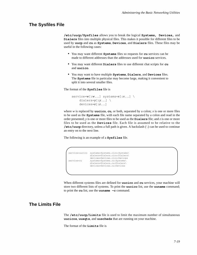
Administering the Basic Networking Utilities
7-19
The Sysfiles File 7
/etc/uucp/Sysfiles allows you to break the logical Systems, Devices, andDialers files into multiple physical files. This makes it possible for different files to beused by uucp and cu as Systems , Devices , and Dialers files. These files may beuseful in the following cases:
• You may want different Systems files so requests for cu services can bemade to different addresses than the addresses used for uucico services.
• You may want different Dialers files to use different chat scripts for cuand uucico .
• You may want to have multiple Systems , Dialers , and Devices files.The Systems file in particular may become large, making it convenient tosplit it into several smaller files.
The format of the Sysfiles file is
service= w[: w . . .] systems= x[: x . . .] \dialers= y[: y . . .] \devices= z[: z . . .]
where w is replaced by uucico , cu , or both, separated by a colon; x is one or more filesto be used as the Systems file, with each file name separated by a colon and read in theorder presented; y is one or more files to be used as the Dialers file; and z is one or morefiles to be used as the Devices file. Each file is assumed to be relative to the/etc/uucp directory, unless a full path is given. A backslash (\ ) can be used to continuean entry on to the next line.
The following is an example of a Sysfiles file.
When different systems files are defined for uucico and cu services, your machine willstore two different lists of systems. To print the uucico list, use the uuname command;to print the cu list, use the uuname -c command.
The Limits File 7
The /etc/uucp/Limits file is used to limit the maximum number of simultaneousuucicos , uuxqts , and uuscheds that are running on your machine.
The format of the Limits file is
service=uucico systems=Systems.cico:Systems\ dialers=Dialers.cico:Dialers\ devices=Devices.cico:Devicesservice=cu systems=Systems.cu:Systems\ dialers=Dialers.cu:Dialers\ devices=Devices.cu:Devices
Network Administration
7-20
service= x max= y
where x can be uucico , uuxqt or uusched , and y is the limit permitted for that service.
The fields are order insensitive and lowercase
The following entries should most commonly be used in the file:
service=uucico max=5service=uuxqt max=2service=uusched max=2
The example allows five uucicos , two uuxqts , and two uuscheds to runsimultaneously.
The Limits file cannot be modified using the system administration menus (accessedthrough the sysadm command). If you want to change the contents of the file, you mustuse one of the UNIX system text editors.
NOTE
Due to the interaction with security levels, the limits are imposedat any given level, although the total uucicos , uuzqts , anduuscheds running on your machine may exceed that limit.
The RLID.map File 7
If you are running the Enhanced Security Utilities or are using cr1 to authenticateconnections, the system administrator must create a RLID.map file. A default file is notdelivered with the system.
The /etc/idmap/attrmap/RLID.map file contains the information used todetermine the LID assigned to an incoming request for access from a remote system. Thefile contains the client system name, the remote system LID which may be matched by theincoming request, and the local LID assigned to the request if there is a match.
Setting up an RLID.map file is described in the Chapter 6, "Administering ID Mapping".
The LIDAUTH.map File 7
If the Enhanced Security Utilities are installed and running on your system, the systemadministrator must create an LIDAUTH.map file. A default file is not delivered with thesystem.
The /etc/idmap/attrmap/LIDAUTH.map file contains the information used todetermine whether the local system is allowed to initiate a connection to a remote systemat the current LID, that is, the LID information for authorizing outgoing requests. TheLIDAUTH.map file is consulted by the Connection Server to determine whether the localsystem is allowed to initiate a connection to a remote system at the current LID. The
Administering the Basic Networking Utilities
7-21
LIDAUTH.map file must contain the remote system name and local LID as input valuesand a local LID or INVALID as output values.
Setting up a LIDAUTH.map file is described in Chapter 4, “Administering the ConnectionServer.”
The Config File 7
The /etc/uucp/Config file allows the administrator to override certain parameterswithin BNU by specifying global BNU options.
Each entry in the Config file has the following format:
parameter=value
Where parameter is one of the configurable parameters and value is the value to beassigned to that parameter. See the Config file provided with your system for a completelist of configurable parameter names.
The following Config file entry sets the default protocol ordering to “Gge” and changesthe “G” protocol defaults to 7 windows and 512-byte packets. See “Protocols” on page7-27.
Protocol=G(7,512)ge
If the system administrator requires authentication of uux requests for all or somesystems, the entry
AUTH=yes
or
AUTH=req
can be included in the Config file. This establishes a global value for BNU. To overridethe global values specified in the Config file, entries may be included in the/etc/uucp/Permissions file for specific machines. See the section on thePermissions file.
If the AUTH option is not included, AUTH defaults to optional (AUTH=opt or AUTH=no).
To specify a key management mechanism, a line of the form
KEYS=name
can be included in the Config file. name is the name of the key management mechanism.For example, to specify that the cr1 key management mechanism is to be used, the entry
KEYS=cr1
should be included in the Config file.
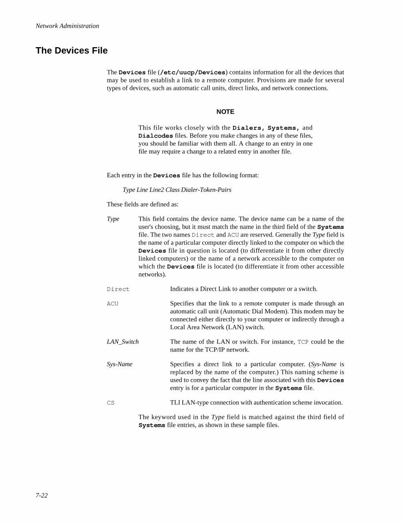
Network Administration
7-22
The Devices File 7
The Devices file (/etc/uucp/Devices ) contains information for all the devices thatmay be used to establish a link to a remote computer. Provisions are made for severaltypes of devices, such as automatic call units, direct links, and network connections.
NOTE
This file works closely with the Dialers, Systems, andDialcodes files. Before you make changes in any of these files,you should be familiar with them all. A change to an entry in onefile may require a change to a related entry in another file.
Each entry in the Devices file has the following format:
Type Line Line2 Class Dialer-Token-Pairs
These fields are defined as:
Type This field contains the device name. The device name can be a name of theuser's choosing, but it must match the name in the third field of the Systemsfile. The two names Direct and ACU are reserved. Generally the Type field isthe name of a particular computer directly linked to the computer on which theDevices file in question is located (to differentiate it from other directlylinked computers) or the name of a network accessible to the computer onwhich the Devices file is located (to differentiate it from other accessiblenetworks).
Direct Indicates a Direct Link to another computer or a switch.
ACU Specifies that the link to a remote computer is made through anautomatic call unit (Automatic Dial Modem). This modem may beconnected either directly to your computer or indirectly through aLocal Area Network (LAN) switch.
LAN_Switch The name of the LAN or switch. For instance, TCP could be thename for the TCP/IP network.
Sys-Name Specifies a direct link to a particular computer. (Sys-Name isreplaced by the name of the computer.) This naming scheme isused to convey the fact that the line associated with this Devicesentry is for a particular computer in the Systems file.
CS TLI LAN-type connection with authentication scheme invocation.
The keyword used in the Type field is matched against the third field ofSystems file entries, as shown in these sample files.
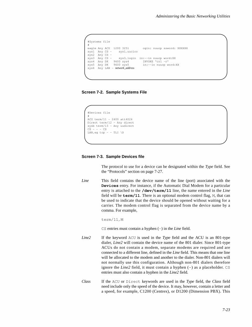
Administering the Basic Networking Utilities
7-23
Screen 7-2. Sample Systems File
Screen 7-3. Sample Devices file
The protocol to use for a device can be designated within the Type field. Seethe “Protocols” section on page 7-27.
Line This field contains the device name of the line (port) associated with theDevices entry. For instance, if the Automatic Dial Modem for a particularentry is attached to the /dev/term/11 line, the name entered in the Linefield will be term/11 . There is an optional modem control flag, M, that canbe used to indicate that the device should be opened without waiting for acarrier. The modem control flag is separated from the device name by acomma. For example,
term/11,M
CS entries must contain a hyphen (- ) in the Line field.
Line2 If the keyword ACU is used in the Type field and the ACU is an 801-typedialer, Line2 will contain the device name of the 801 dialer. Since 801-typeACUs do not contain a modem, separate modems are required and areconnected to a different line, defined in the Line field. This means that one linewill be allocated to the modem and another to the dialer. Non-801 dialers willnot normally use this configuration. Although non-801 dialers thereforeignore the Line2 field, it must contain a hyphen (- ) as a placeholder. CSentries must also contain a hyphen in the Line2 field.
Class If the ACU or Direct keywords are used in the Type field, the Class fieldneed include only the speed of the device. It may, however, contain a letter anda speed, for example, C1200 (Centrex), or D1200 (Dimension PBX). This
#Systems file#eagle Any ACU 1200 3251 ogin: nuucp ssword: XXXXXXsys1 Any CS - sys1,uucicosys2 Any CS -sys3 Any CS - sys3,login in:--in nuucp word:XXsys4 Any DK 9600 sys4 INVOKE "cr1 -r"sys5 Any DK 9600 sys5 in:--in nuucp word:XXsys6 Any LAN - network_address
#Devices file#ACU term/11 - 2400 att4024Direct term/12 - Any directsysb term/13 - Any uudirectCS - - - CSLAN,eg tcp - - TLI \D
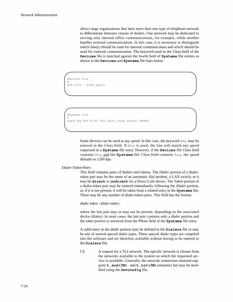
Network Administration
7-24
allows large organizations that have more than one type of telephone networkto differentiate between classes of dialers. One network may be dedicated toserving only internal office communications, for example, while anotherhandles external communications. In this case, it is necessary to distinguishwhich line(s) should be used for internal communication and which should beused for external communication. The keyword used in the Class field of theDevices file is matched against the fourth field of Systems file entries asshown in the Devices and Systems file lines below.
Some devices can be used at any speed. In this case, the keyword Any may beentered in the Class field. If Any is used, the line will match any speedrequested in a Systems file entry. However, if the Devices file Class fieldcontains Any and the Systems file Class field contains Any, the speeddefaults to 1200 bps.
Dialer-Token-PairsThis field contains pairs of dialers and tokens. The Dialer portion of a dialer-token pair may be the name of an automatic dial modem, a LAN switch, or itmay be direct or undirect for a Direct Link device. The Token portion ofa dialer-token pair may be entered immediately following the Dialer portion,or, if it is not present, it will be taken from a related entry in the Systems file.There may be any number of dialer-token pairs. This field has the format:
dialer token [ dialer token]
where the last pair may or may not be present, depending on the associateddevice (dialer). In most cases, the last pair contains only a dialer portion andthe token portion is retrieved from the Phone field of the Systems file entry.
A valid entry in the dialer portion may be defined in the Dialers file or maybe one of several special dialer types. These special dialer types are compiledinto the software and are therefore available without having to be entered inthe Dialers file.
CS A request for a TLI network. The specific network is chosen fromthe networks available to the system on which the requested ser-vice is available. Generally, the network connection returned sup-ports t_snd(3N) and t_rcv(3N ) semantics but may be mod-ified using the Devconfig file.
#Devices file#ACU tty11 - D1200 penril
#Systems file#eagle Any ACU D1200 3251 ogin: nuucp ssword: XXXXXX
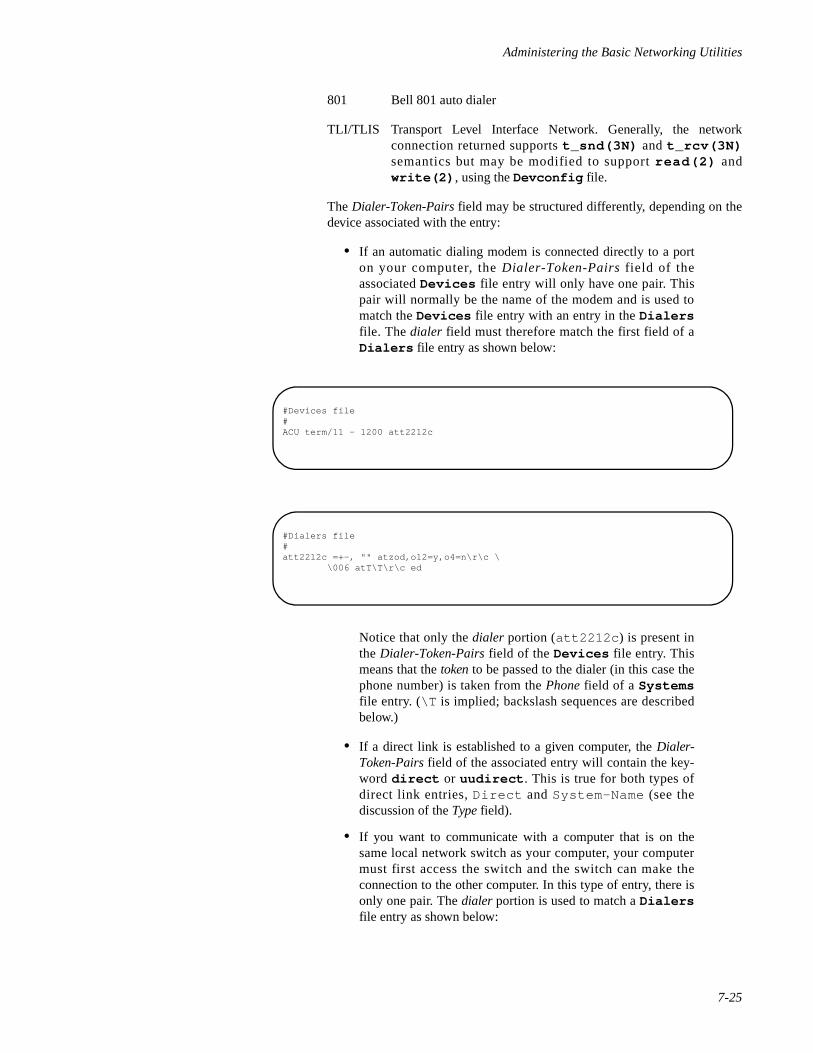
Administering the Basic Networking Utilities
7-25
801 Bell 801 auto dialer
TLI/TLIS Transport Level Interface Network. Generally, the networkconnection returned supports t_snd(3N) and t_rcv(3N)semantics but may be modified to support read(2) andwrite(2) , using the Devconfig file.
The Dialer-Token-Pairs field may be structured differently, depending on thedevice associated with the entry:
• If an automatic dialing modem is connected directly to a porton your computer, the Dialer-Token-Pairs field of theassociated Devices file entry will only have one pair. Thispair will normally be the name of the modem and is used tomatch the Devices file entry with an entry in the Dialersfile. The dialer field must therefore match the first field of aDialers file entry as shown below:
Notice that only the dialer portion (att2212c ) is present inthe Dialer-Token-Pairs field of the Devices file entry. Thismeans that the token to be passed to the dialer (in this case thephone number) is taken from the Phone field of a Systemsfile entry. (\T is implied; backslash sequences are describedbelow.)
• If a direct link is established to a given computer, the Dialer-Token-Pairs field of the associated entry will contain the key-word direct or uudirect . This is true for both types ofdirect link entries, Direct and System-Name (see thediscussion of the Type field).
• If you want to communicate with a computer that is on thesame local network switch as your computer, your computermust first access the switch and the switch can make theconnection to the other computer. In this type of entry, there isonly one pair. The dialer portion is used to match a Dialersfile entry as shown below:
#Devices file#ACU term/11 - 1200 att2212c
#Dialers file#att2212c =+-, "" atzod,o12=y,o4=n\r\c \ \006 atT\T\r\c ed
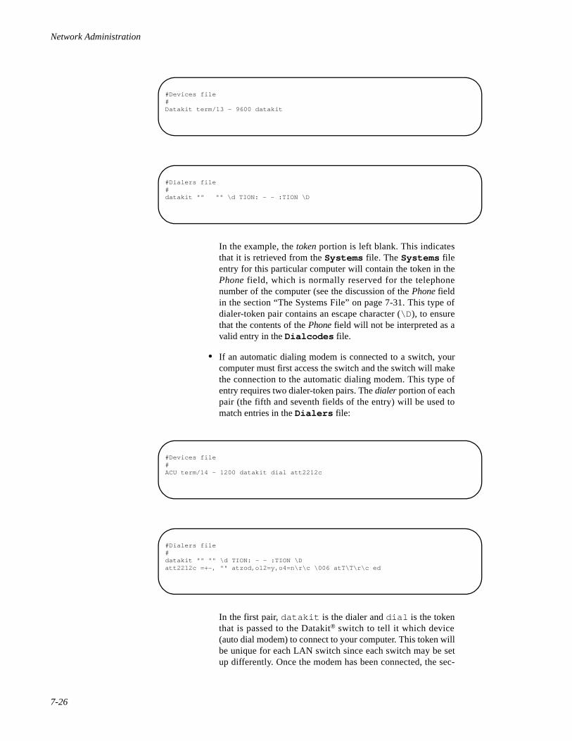
Network Administration
7-26
In the example, the token portion is left blank. This indicatesthat it is retrieved from the Systems file. The Systems fileentry for this particular computer will contain the token in thePhone field, which is normally reserved for the telephonenumber of the computer (see the discussion of the Phone fieldin the section “The Systems File” on page 7-31. This type ofdialer-token pair contains an escape character (\D ), to ensurethat the contents of the Phone field will not be interpreted as avalid entry in the Dialcodes file.
• If an automatic dialing modem is connected to a switch, yourcomputer must first access the switch and the switch will makethe connection to the automatic dialing modem. This type ofentry requires two dialer-token pairs. The dialer portion of eachpair (the fifth and seventh fields of the entry) will be used tomatch entries in the Dialers file:
In the first pair, datakit is the dialer and dial is the tokenthat is passed to the Datakit® switch to tell it which device(auto dial modem) to connect to your computer. This token willbe unique for each LAN switch since each switch may be setup differently. Once the modem has been connected, the sec-
#Devices file#Datakit term/13 - 9600 datakit
#Dialers file#datakit "" "" \d TION: - - :TION \D
#Devices file#ACU term/14 - 1200 datakit dial att2212c
#Dialers file#datakit "" "" \d TION: - - :TION \Datt2212c =+-, "" atzod,o12=y,o4=n\r\c \006 atT\T\r\c ed
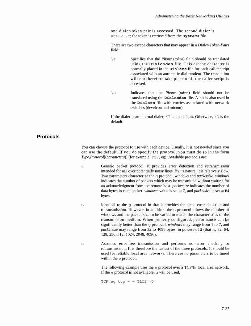
Administering the Basic Networking Utilities
7-27
ond dialer-token pair is accessed. The second dialer isatt2212c ; the token is retrieved from the Systems file.
There are two escape characters that may appear in a Dialer-Token-Pairsfield:
\T Specifies that the Phone (token) field should be translatedusing the Dialcodes file. This escape character isnormally placed in the Dialers file for each caller scriptassociated with an automatic dial modem. The translationwill not therefore take place until the caller script isaccessed.
\D Indicates that the Phone (token) field should not betranslated using the Dialcodes file. A \D is also used inthe Dialers file with entries associated with networkswitches (develcon and micom).
If the dialer is an internal dialer, \T is the default. Otherwise, \D is thedefault.
Protocols 7
You can choose the protocol to use with each device. Usually, it is not needed since youcan use the default. If you do specify the protocol, you must do so in the formType,Protocol[(parameters)] (for example, TCP,eg). Available protocols are:
g Generic packet protocol. It provides error detection and retransmissionintended for use over potentially noisy lines. By its nature, it is relatively slow.Two parameters characterize the g protocol, windows and packetsize. windowsindicates the number of packets which may be transmitted without waiting foran acknowledgment from the remote host. packetsize indicates the number ofdata bytes in each packet. windows value is set at 7, and packetsize is set at 64bytes.
G Identical to the g protocol in that it provides the same error detection andretransmission. However, in addition, the G protocol allows the number ofwindows and the packet size to be varied to match the characteristics of thetransmission medium. When properly configured, performance can besignificantly better than the g protocol. windows may range from 1 to 7, andpacketsize may range from 32 to 4096 bytes, in powers of 2 (that is, 32, 64,128, 256, 512, 1024, 2048, 4096).
e Assumes error-free transmission and performs no error checking orretransmission. It is therefore the fastest of the three protocols. It should beused for reliable local area networks. There are no parameters to be tunedwithin the e protocol.
The following example uses the e protocol over a TCP/IP local area network.If the e protocol is not available, g will be used.
TCP,eg tcp - - TLIS \D
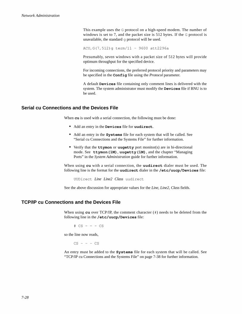
Network Administration
7-28
This example uses the G protocol on a high-speed modem. The number ofwindows is set to 7, and the packet size is 512 bytes. If the G protocol isunavailable, the standard g protocol will be used.
ACU,G(7,512)g term/11 - 9600 att2296a
Presumably, seven windows with a packet size of 512 bytes will provideoptimum throughput for the specified device.
For incoming connections, the preferred protocol priority and parameters maybe specified in the Config file using the Protocol parameter.
A default Devices file containing only comment lines is delivered with thesystem. The system administrator must modify the Devices file if BNU is tobe used.
Serial cu Connections and the Devices File 7
When cu is used with a serial connection, the following must be done:
• Add an entry in the Devices file for uudirect .
• Add an entry in the Systems file for each system that will be called. See“Serial cu Connections and the Systems File” for further information.
• Verify that the ttymon or uugetty port monitor(s) are in bi-directionalmode. See ttymon(1M) , uugetty(1M) , and the chapter “ManagingPorts” in the System Administration guide for further information.
When using cu with a serial connection, the uudirect dialer must be used. Thefollowing line is the format for the uudirect dialer in the /etc/uucp/Devices file:
UUDirect Line Line2 Class uudirect
See the above discussion for appropriate values for the Line, Line2, Class fields.
TCP/IP cu Connections and the Devices File 7
When using cu over TCP/IP, the comment character (#) needs to be deleted from thefollowing line in the /etc/uucp/Devices file:
# CS - - - CS
so the line now reads,
CS - - - CS
An entry must be added to the Systems file for each system that will be called. See“TCP/IP cu Connections and the Systems File” on page 7-38 for further information.
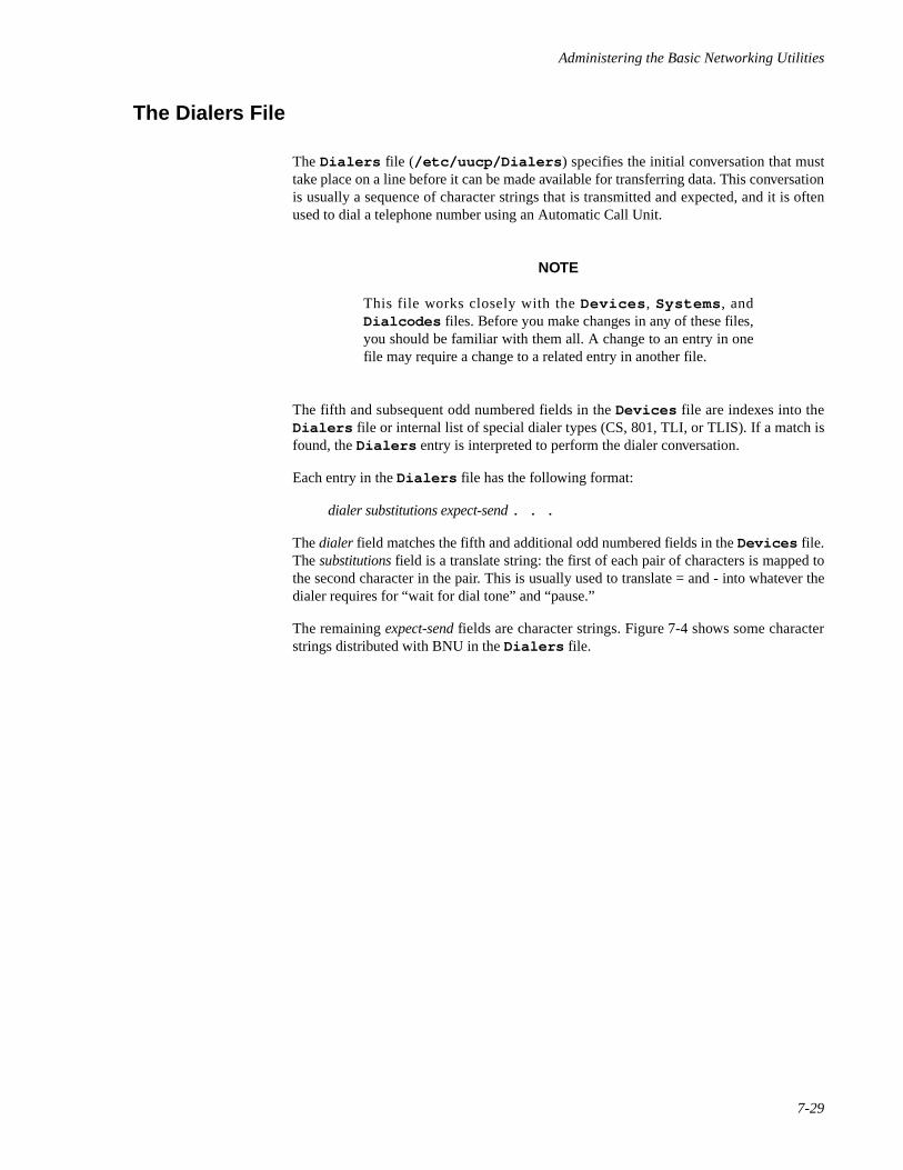
Administering the Basic Networking Utilities
7-29
The Dialers File 7
The Dialers file (/etc/uucp/Dialers ) specifies the initial conversation that musttake place on a line before it can be made available for transferring data. This conversationis usually a sequence of character strings that is transmitted and expected, and it is oftenused to dial a telephone number using an Automatic Call Unit.
NOTE
This file works closely with the Devices , Systems , andDialcodes files. Before you make changes in any of these files,you should be familiar with them all. A change to an entry in onefile may require a change to a related entry in another file.
The fifth and subsequent odd numbered fields in the Devices file are indexes into theDialers file or internal list of special dialer types (CS, 801, TLI, or TLIS). If a match isfound, the Dialers entry is interpreted to perform the dialer conversation.
Each entry in the Dialers file has the following format:
dialer substitutions expect-send . . .
The dialer field matches the fifth and additional odd numbered fields in the Devices file.The substitutions field is a translate string: the first of each pair of characters is mapped tothe second character in the pair. This is usually used to translate = and - into whatever thedialer requires for “wait for dial tone” and “pause.”
The remaining expect-send fields are character strings. Figure 7-4 shows some characterstrings distributed with BNU in the Dialers file.
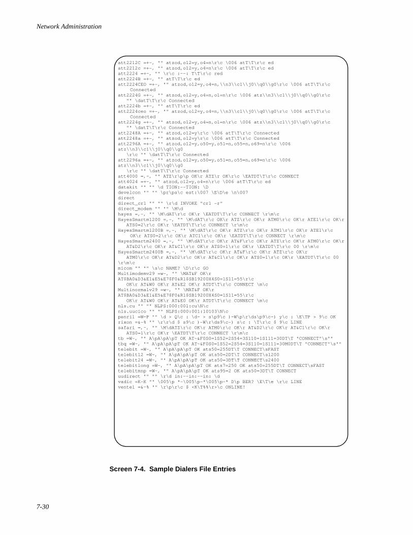
Network Administration
7-30
Screen 7-4. Sample Dialers File Entries
att2212C =+-, "" atzod,o12=y,o4=n\r\c \006 atT\T\r\c edatt2212c =+-, "" atzod,o12=y,o4=n\r\c \006 atT\T\r\c edatt2224 =+-, "" \r\c :--: T\T\r\c redatt2224B =+-, "" atT\T\r\c edatt2224CEO =+-, "" atzod,o12=y,o4=n,\\n3\\c1\\j0\\q0\\g0\r\c \006 atT\T\r\c
Connectedatt2224G =+-, "" atzod,o12=y,o4=n,o1=n\r\c \006 atz\\n3\\c1\\j0\\q0\\g0\r\c "" \datT\T\r\c Connectedatt2224b =+-, "" atT\T\r\c edatt2224ceo =+-, "" atzod,o12=y,o4=n,\\n3\\c1\\j0\\q0\\g0\r\c \006 atT\T\r\c
Connectedatt2224g =+-, "" atzod,o12=y,o4=n,o1=n\r\c \006 atz\\n3\\c1\\j0\\q0\\g0\r\c "" \datT\T\r\c Connectedatt2248A =+-, "" atzod,o12=y\r\c \006 atT\T\r\c Connectedatt2248a =+-, "" atzod,o12=y\r\c \006 atT\T\r\c Connectedatt2296A =+-, "" atzod,o12=y,o50=y,o51=n,o55=n,o69=n\r\c \006 atz\\n3\\c1\\j0\\q0\\g0 \r\c "" \datT\T\r\c Connectedatt2296a =+-, "" atzod,o12=y,o50=y,o51=n,o55=n,o69=n\r\c \006 atz\\n3\\c1\\j0\\q0\\g0 \r\c "" \datT\T\r\c Connectedatt4000 =,-, "" ATZ\r\p\p OK\r ATZ\r OK\r\c \EATDT\T\r\c CONNECTatt4024 =+-, "" atzod,o12=y,o4=n\r\c \006 atT\T\r\c eddatakit "" "" \d TION:--TION: \Ddevelcon "" "" \pr\ps\c est:\007 \E\D\e \n\007directdirect_cr1 "" "" \r\d INVOKE "cr1 -r"direct_modem "" "" \M\dhayes =,-, "" \M\dAT\r\c OK\r \EATDT\T\r\c CONNECT \r\m\cHayesSmartm1200 =,-, "" \M\dAT\r\c OK\r ATZ\r\c OK\r ATM0\r\c OK\r ATE1\r\c OK\r ATS0=2\r\c OK\r \EATDT\T\r\c CONNECT \r\m\cHayesSmartm1200B =,-, "" \M\dAT\r\c OK\r ATZ\r\c OK\r ATM1\r\c OK\r ATE1\r\c
OK\r ATS0=2\r\c OK\r ATC1\r\c OK\r \EATDT\T\r\c CONNECT \r\m\cHayesSmartm2400 =,-, "" \M\dAT\r\c OK\r AT&F\r\c OK\r ATZ\r\c OK\r ATM0\r\c OK\r AT&D2\r\c OK\r AT&C1\r\c OK\r ATS0=1\r\c OK\r \EATDT\T\r\c 00 \r\m\cHayesSmartm2400B =,-, "" \M\dAT\r\c OK\r AT&F\r\c OK\r ATZ\r\c OK\r ATM0\r\c OK\r AT&D2\r\c OK\r AT&C1\r\c OK\r ATS0=1\r\c OK\r \EATDT\T\r\c 00 \r\m\cmicom "" "" \s\c NAME? \D\r\c GOMultimodemv29 =w-, "" \MAT&F OK\r AT$BA0&D3&E1&E5&E7$F0&R1$SB19200X4S0=1S11=55\r\c OK\r AT&W0 OK\r AT&E2 OK\r ATDT\T\r\c CONNECT \m\cMultinormalv29 =w-, "" \MAT&F OK\r AT$BA0&D3&E1&E5&E7$F0&R1$SB19200X4S0=1S11=55\r\c OK\r AT&W0 OK\r AT&E0 OK\r ATDT\T\r\c CONNECT \m\cnls.cu "" "" NLPS:000:001:cu\N\cnls.uucico "" "" NLPS:000:001:10103\N\cpenril =W-P "" \d > Q\c : \d- > s\p9\c )-W\p\r\ds\p9\c-) y\c : \E\TP > 9\c OKrixon =&-% "" \r\r\d $ s9\c )-W\r\ds9\c-) s\c : \T\r\c $ 9\c LINEsafari =,-, "" \M\dATZ\r\c OK\r ATM0\r\c OK\r AT&D2\r\c OK\r AT&C1\r\c OK\r ATS0=1\r\c OK\r \EATDT\T\r\c CONNECT \r\m\ctb =W-, "" A\pA\pA\pT OK AT~&F0S0=1S52=2S54=3S110=1S111=30DT\T "CONNECT"\s""tbq =W-, "" A\pA\pA\pT OK AT~&F0S0=1S52=2S54=3S110=1S111=30M0DT\T "CONNECT"\s""telebit =W-, "" A\pA\pA\pT OK ats50=255DT\T CONNECT\sFASTtelebit12 =W-, "" A\pA\pA\pT OK ats50=2DT\T CONNECT\s1200telebit24 =W-, "" A\pA\pA\pT OK ats50=3DT\T CONNECT\s2400telebitlong =W-, "" A\pA\pA\pT OK ats7=250 OK ats50=255DT\T CONNECT\sFASTtelebitmnp =W-, "" A\pA\pA\pT OK ats95=2 OK ats50=3DT\T CONNECTuudirect "" "" \r\d in:--in:--in: \dvadic =K-K "" \005\p *-\005\p-*\005\p-* D\p BER? \E\T\e \r\c LINEventel =&-% "" \r\p\r\c $ <K\T%%\r>\c ONLINE!
Administering the Basic Networking Utilities
7-31
The escape characters (those beginning with “\ ”) used in the Dialers are explained inthe following section, “The Systems File.”
The att2212c entry in the Dialers file is processed in two steps. First, the telephonenumber argument is translated as follows:
- Any equals sign (=) is replaced by a plus sign (+)
- Any minus sign (- ) is replaced by a comma (, )
The plus sign and comma in the translated telephone number argument have the followingvalues:
+ Wait for dial tone.
, Pause.
Second, the handshake given by the remainder of the line is interpreted as follows:
"" Wait for nothing, that is, proceed to the expect-send string.
atzod Enter command mode, reset modem, set options to default.
o12=y Set option 12 to y (transparent data mode).
o4=n\r\c Set option 4 to n (don't disconnect on received spaces).Terminate with a carriage return but no newline.
\006 Wait for acknowledge signal (ACK).
atT\T\r\c Enter command mode. Use tone dialing. Translate thephone number and terminate with a carriage return, but nonewline.
ed Expect “ed” (as in the last two letters of answered).
The Systems File 7
The Systems file (/etc/uucp/Systems ) must contain an entry for each system BNUis allowed to communicate with. Each entry in the file represents a computer that can becalled by the local machine in its role as client machine and contains the information theConnection Server daemon needs to establish a communication link. The BasicNetworking software is configured to prevent any remote system not included in the localmachine's Systems file from logging in. That is, the local machine can not communicatewith any machine that is not listed in its Systems file, either in the role of client machineor server machine. See the section on the remote.unknown file. There may be morethan one entry for a particular computer. The additional entries represent alternativecommunication paths that will be tried in sequential order.
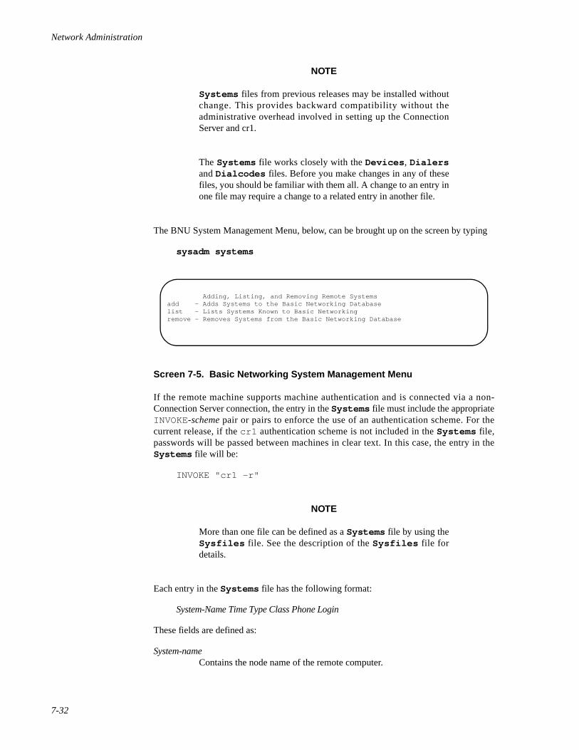
Network Administration
7-32
NOTE
Systems files from previous releases may be installed withoutchange. This provides backward compatibility without theadministrative overhead involved in setting up the ConnectionServer and cr1.
The Systems file works closely with the Devices , Dialersand Dialcodes files. Before you make changes in any of thesefiles, you should be familiar with them all. A change to an entry inone file may require a change to a related entry in another file.
The BNU System Management Menu, below, can be brought up on the screen by typing
sysadm systems
Screen 7-5. Basic Networking System Management Menu
If the remote machine supports machine authentication and is connected via a non-Connection Server connection, the entry in the Systems file must include the appropriateINVOKE-scheme pair or pairs to enforce the use of an authentication scheme. For thecurrent release, if the cr1 authentication scheme is not included in the Systems file,passwords will be passed between machines in clear text. In this case, the entry in theSystems file will be:
INVOKE "cr1 -r"
NOTE
More than one file can be defined as a Systems file by using theSysfiles file. See the description of the Sysfiles file fordetails.
Each entry in the Systems file has the following format:
System-Name Time Type Class Phone Login
These fields are defined as:
System-nameContains the node name of the remote computer.
Adding, Listing, and Removing Remote Systemsadd - Adds Systems to the Basic Networking Databaselist - Lists Systems Known to Basic Networkingremove - Removes Systems from the Basic Networking Database
Administering the Basic Networking Utilities
7-33
Time Specifies when the remote system can be used. Time is a string that specifiesboth the day of the week and the time of day when the remote system can becalled. The format of the Time field is:
daytime[ ;retry]
day may be a list containing some of the following:
Su Mo Tu We Th Fr Safor individual days
Wk for any weekday (Mo Tu We Th Fr)
Any for any day
Never for a passive arrangement with the remote computer. If the Timefield is Never , the local computer will never initiate a call to theremote computer. The call must be initiated by the remotecomputer. In other words, the local computer is passive withrespect to the remote computer. (See “The Permissions File” onpage 7-10.)
time should be a range of times specified in 24-hour notation, for example0800-1230 for “8:30 A.M. to 12:30 P.M.” If no time portion is specified, anytime of day is assumed to be allowed for the call. A time range that spans 0000is permitted. For example, 0800-0600 means all times are allowed otherthan times between 6 A.M. and 8 A.M.
An optional subfield, retry, is available to specify the minimum time (inminutes) before a retry, following a failed attempt. The default wait is fiveminutes. The subfield separator is a semicolon (;). For example, Any;9 isinterpreted as call any time, but wait at least nine minutes before retrying aftera failure occurs. The following is a sample time entry:
Wk1700-0800,Sa,Su
The example allows calls from 5:00 P.M. to 8:00 A.M., Monday throughFriday, and calls any time Saturday and Sunday. In this example, calls areallowed only when telephone rates are low.
Any and Never are the most common entries in the Time field.
Type The Type field contains the device type used to establish a communication linkwith a remote computer. It is used to access the entry in the Devices file.The Systems file Type entry is matched against the first field of theDevices file entries.
The protocol used to contact the system can be defined by adding the protocolidentifier to the Type field. If the Type is CS and the protocol string in theDevices file specified that the e or g protocol should be used, the stringentered in the Type field of the Systems file could be CSeg. The use of theprotocol information from the Devices file as part of the Type entry in theSystems file is optional but it is often included to make these files easier tounderstand. The device type and the protocols must be comma separated. Inthe Systems file example below, the protocol g is attached to the device typeACU. See “Protocols” on page 7-27.
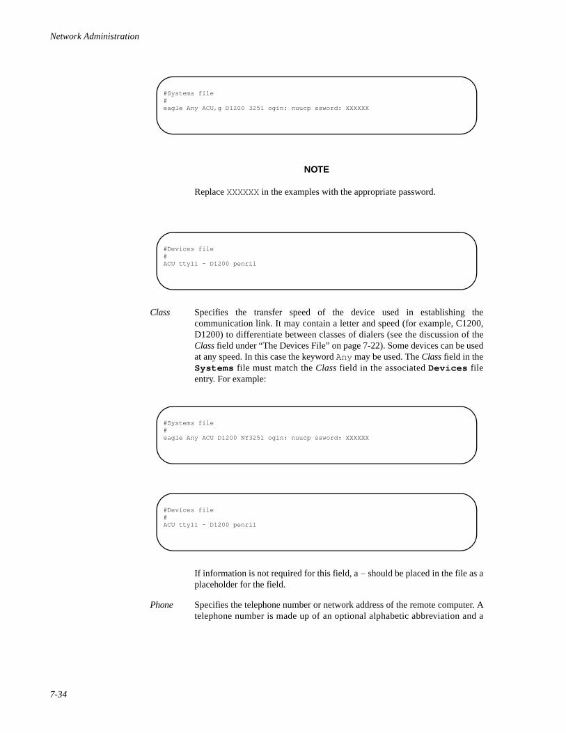
Network Administration
7-34
NOTE
Replace XXXXXX in the examples with the appropriate password.
Class Specifies the transfer speed of the device used in establishing thecommunication link. It may contain a letter and speed (for example, C1200,D1200) to differentiate between classes of dialers (see the discussion of theClass field under “The Devices File” on page 7-22). Some devices can be usedat any speed. In this case the keyword Any may be used. The Class field in theSystems file must match the Class field in the associated Devices fileentry. For example:
If information is not required for this field, a - should be placed in the file as aplaceholder for the field.
Phone Specifies the telephone number or network address of the remote computer. Atelephone number is made up of an optional alphabetic abbreviation and a
#Systems file#eagle Any ACU,g D1200 3251 ogin: nuucp ssword: XXXXXX
#Devices file#ACU tty11 - D1200 penril
#Systems file#eagle Any ACU D1200 NY3251 ogin: nuucp ssword: XXXXXX
#Devices file#ACU tty11 - D1200 penril
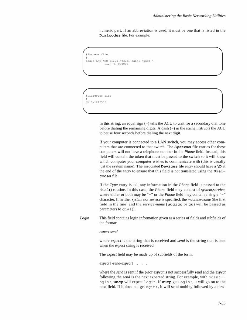
Administering the Basic Networking Utilities
7-35
numeric part. If an abbreviation is used, it must be one that is listed in theDialcodes file. For example:
In this string, an equal sign (=) tells the ACU to wait for a secondary dial tonebefore dialing the remaining digits. A dash (- ) in the string instructs the ACUto pause four seconds before dialing the next digit.
If your computer is connected to a LAN switch, you may access other com-puters that are connected to that switch. The Systems file entries for thesecomputers will not have a telephone number in the Phone field. Instead, thisfield will contain the token that must be passed to the switch so it will knowwhich computer your computer wishes to communicate with (this is usuallyjust the system name). The associated Devices file entry should have a \D atthe end of the entry to ensure that this field is not translated using the Dial-codes file.
If the Type entry is CS, any information in the Phone field is passed to thedial () routine. In this case, the Phone field may consist of system,service,where either or both may be “- ” or the Phone field may contain a single “- ”character. If neither system nor service is specified, the machine-name (the firstfield in the line) and the service-name (uucico or cu ) will be passed asparameters to dial ().
Login This field contains login information given as a series of fields and subfields ofthe format:
expect send
where expect is the string that is received and send is the string that is sentwhen the expect string is received.
The expect field may be made up of subfields of the form:
expect[ -send-expect] . . .
where the send is sent if the prior expect is not successfully read and the expectfollowing the send is the next expected string. For example, with ogin:--ogin: , uucp will expect login . If uucp gets ogin: , it will go on to thenext field. If it does not get ogin: , it will send nothing followed by a new-
#Systems file#eagle Any ACU D1200 NY3251 ogin: nuucp \
ssword: XXXXXX
#Dialcodes file#NY 9=1212555
Network Administration
7-36
line, then look for ogin again. If no characters are initially expected from theremote computer, the characters "" (null string) should be used in the firstexpect field. Note that all send fields will be sent followed by a newline unlessthe send string is terminated with a \c .
NOTE
The “l ” and other initial characters are often omitted from chatscripts since chat scripts are case-sensitive. Some systems capital-ize the first letter of prompts while others do not.
Here is an example of a Systems file entry that uses an expect-send string:
owl Any ACU 1200 Chicago6013 "" \r ogin:-BREAK-ogin: \uucpx word: xyzzy
This example says don't wait, just send a carriage return and wait for ogin: (forLogin: ). If you don't get ogin , send a BREAK. When you do get ogin: send the loginname uucpx , then when you get word: (for Password :), send the password xyzzy .
There are several escape characters that cause specific actions when they are a part of astring sent during the login sequence. The following escape characters are useful whenusing BNU communications:
\b Send or expect a backspace character
\c If at the end of a string, suppress the newline that is normally sent.Ignored otherwise.
\d Delay two seconds before sending or reading more characters
\p Pause for approximately ¼ to ½ second
\E Start echo checking. (From this point on, whenever a character istransmitted, it will wait for the character to be received beforedoing anything else.)
\e Echo check off
\M Turn on CLOCAL flag
\m Turn off CLOCAL flag
\n Send a newline character
\r Send or expect a carriage-return
\s Send or expect a space character
\t Send or expect a tab character
\\ Send or expect a \ character
BREAK Send or expect a BREAK character
Administering the Basic Networking Utilities
7-37
\D Telephone number or token without Dialcodes translation
EOT Send or expect EOT newline twice
\K Same as BREAK
\N Send or expect a null character (ASCII NUL)
\T Telephone number or token with Dialcodes translation
\ddd Collapse the octal digits (ddd) into a single character
~nn Specify the timeout by appending nn to the expect string, wherenn is the timeout time in seconds.
The Login field may contain the keyword INVOKE followed by white space followed bythe name of an authentication scheme. This pair may appear several times in the Loginfield of a Systems file entry if more than one authentication step is expected to takeplace. The following is an example of a Systems file entry that specifies more than oneauthentication step:
systemX Any ACU 1200 95551234 INVOKE "inap -r" \INVOKE "cr1 -r"
systemX is understood to be a valid system name.
If the expect string consists of the keyword ABORT, then the string after it is used to arman abort trap. If that string is subsequently received any time prior to the completion of theentire expect/send script, then uucico aborts, as it would if the script had timed out.This is useful for trapping error messages—such as Host Unavailable or Systemis Down — from port selectors or front-end processors. Note that in an expect/sendscript, the format in which the ABORT appears is backward: ABORT expect instead ofexpect ABORT .
NOTE
The entire Login field is ignored for cu and ct service requestssince the user is expected to enter the proper connect sequencemanually. This means that Login chat scripts that include anINVOKE statement will also be ignored when the service beingrequested is cu or ct .
The system administrator must create the entries in the Systems file. A Systems file isdelivered with the system but contains only comment lines.
Serial cu Connections and the Systems File 7
When cu is used with a serial connection, the following must be done:
• Add an entry in the Devices file for uudirect . See “Serial cu Connec-tions and the Devices File” on page 7-28.
• Add an entry in the Systems file for each system that will be called.
Network Administration
7-38
• Verify that the ttymon or uugetty port monitor(s) are in bi-directionalmode. See ttymon(1M ), uugetty(1M) , and the chapter “ManagingPorts” in the System Administration guide for further information.
When using cu with a serial connection, the uudirect dialer must be used.
System-Name Time UUDirect Class Phone Login
See the above discussion for appropriate values for the System-Name, Time, Class, Phone,and Login fields.
TCP/IP cu Connections and the Systems File 7
When using cu over TCP/IP, an entry for each system that is to be called must be added tothe Systems file. The entry has the following format:
System-Name Time CS - -,listen:cu
See the above discussion for appropriate values for the System-Name and Time fields.
The Devices file must also be modified to support cu over TCP/IP. See “TCP/IP cuConnections and the Devices File” on page 7-28 for further information.
The Dialcodes File 7
The Dialcodes file (/etc/uucp/Dialcodes ) contains the dial-code abbreviationsthat can be used in the Phone field of the Systems file.
NOTE
The Dialcodes fi le works closely with the Devices ,Dialers and Systems files. Before you make changes in anyof these files, you should be familiar with them all. A change to anentry in one file may require a change to a related entry in anotherfile.
Each Dialcodes entry has the format:
abb dial-seq
where abb is the abbreviation used in the Systems file Phone field and dial-seq is the dialsequence that is passed to the dialer when that particular Systems file entry is accessed.
The entry
jt 9=555-
would be set up to work with a Phone field in the Systems file such as jt7867 . Whenthe entry containing jt7867 is encountered, the sequence 9=555-7867 would be sentto the dialer if the token in the dialer-token pair is \T .

Administering the Basic Networking Utilities
7-39
The default Dialcodes file delivered with the system is empty. It is not necessary for thesystem administrator to do anything to the file.
The Poll File 7
The Poll file (/etc/uucp/Poll ) contains information for polling remote computers.Each entry in the Poll file contains the name of a remote computer to call, followed by atab character (a space won't work), and finally the hours the computer should be called.
The format for entries in the Poll file is:
sys-name<tab> hour. . .
For example the entry:
eagle 0 4 8 12 16 20
polls the computer eagle every four hours.
The uudemon.poll script does not actually perform the poll. It merely sets up a pollingwork file (always named C. file) in the spool directory. uudemon.hour starts thescheduler; it is the scheduler that examines all work files in the spool directory and doesthe polling.
A default Poll file is delivered with the system and does not need to be modified.
The Grades File 7
The Grades file (/etc/uucp/Grades ) contains the definitions for the job grades thatmay be used to queue jobs to a remote computer. It also contains the permissions for eachjob grade. Each entry in this file represents a definition of an administrator defined jobgrade that allows users to queue jobs.
Each entry in the Grades file has the following format:
User-job-grade System-job-grade Job-size Permit-type ID-list
Each entry in this file contains fields that are separated by white space. The last field in theentry is made up of sub-fields that are also white space separated. If a entry takes up morethan one physical line, then a backslash (\), is used to continue the entry onto the followingline. Comment lines begin with a pound sign (#) and occupy the entire line. Blank linesare always ignored. Here is a description of each field:
User-job-gradeThis field contains an administrative defined user job grade name of up to 64characters.
System-job-gradeThis field contains a one character job grade to which User-job-grade will bemapped. The valid list of characters is A-Z, a-z, with A having the highestpriority and z the lowest.

Network Administration
7-40
Job-size This field specifies the maximum job size that can be entered in the queue.Job-size is measured in bytes and may be a list of the following:
nnnn where nnnn is an integer that specifies the maximum job size forthis job grade
nK where n is a decimal number that represents the number of kilo-bytes and K is an abbreviation for kilobyte
nM where n is a decimal number that represents the number of mega-bytes and M is an abbreviation for megabyte
Any a keyword to specify that there is no maximum job size
Here are some examples:
5000 represents 5000 bytes
10K represents 10 kilobytes
2M represents 2 megabytes
Permit-typeThis field contains a keyword that denotes how to interpret the ID list. Thefollowing list contains the keywords and their meanings:
User ID list contains the login names of users permitted to use this jobgrade.
Non-userID list contains the login names of users not permitted to use thisjob grade.
Group ID list contains the group names whose members are permitted touse this group.
Non-groupID list contains the group names whose members are notpermitted to use this job grade.
ID-list This contains a list of login names or group names that are to be permitted ordenied queuing to this job grade. The list of names are separated by whitespace and terminated by a newline character. The keyword Any is used todenote that anyone is permitted to queue to this job grade.
The user job grade may be bound to more than one system job grade. It is important tonote that the Grades file will be searched sequentially for occurrences of a user jobgrade. Therefore, any multiple occurrences of a system job grade should be listedaccording to the restriction on the maximum job size.
While there is no maximum number for the user job grades, the maximum number ofsystem job grades allowed is 52. The reason is that more than one User-job-grade can bemapped to a System-job-grade, but each User-job-grade job grade must be on a separateline in the Grades file. For example:
mail N Any User Anynetnews N Any User Any
Administering the Basic Networking Utilities
7-41
Given this configuration in a Grades file, these two User-job-grade grades will share thesame System-job-grade. Since the permissions for a Job-grade are associated with a User-job-grade and not a System-job-grade, it is even possible for two User-job-grades to sharethe same System-job-grades and have two different sets of permissions for each one.
Default Grade 7
The binding of a default User-job-grade to a system job grade can be defined by theadministrator. The administrator must use the keyword default as user job grade in theUser-job-grade field of the Grades file and the system job grade that it is bound to. Therestrictions and ID fields should be defined as Any so that any user and any size job can bequeued to this grade. Here's an example:
default a Any User Any
If the default user job grade is not defined by the administrator, then the built-in defaultgrade, Z, will be used. Because it is assumed that the restriction field is Any, multipleoccurrences of the default grade are not checked.
The Grades file delivered with the system contains the following three default grades:
high F Any User Anymedium S Any User Anylow n Any User Any
The file must be administered only if you are using grades. If you are not using grades, it isnot necessary to modify the file.
Administrative Support Files 7
The Basic Networking administrative files are described below. These files are created inspool directories to hold temporary data or store information about remote transfers orexecutions.
TM. (temporary data file)These data files are created by Basic Networking processes under the spooldirectory (that is, /var/spool/uucp/ X) when a file is received fromanother computer. The directory X has the same name as the remote computerthat is sending the file. The names of the temporary data files have the format:
TM.pid.ddd
where pid is a process-ID and ddd is a sequential three-digit number starting at0.
When the entire file is received, the TM. pid.ddd file is moved or copied to thepathname specified in the C. sysnxxxx file (discussed below) that caused thetransmission. If processing is abnormally terminated, the TM.pid.ddd file mayremain in the X directory. These files should be automatically removed byuucleanup .
Network Administration
7-42
P. (checkpoint file)A checkpoint file is created when processing terminates abnormally. Unlikethe TM.pid.ddd file, it is not removed. Therefore, when the transfer session isre-established, the length of the checkpoint file serves as an appropriateplace to restart the transfer of the file, instead of restarting from the beginning.When checkpointing is specified for a file being transferred from anothercomputer, the checkpoint file is used instead of a TM file. checkpoint filesare created in the spool directory. Checkpointing occurs only between twosystems that have the BNU enhancements introduced in the OS.The names ofthe checkpoint files have the following format:
P. systmxxxxyyy
where systm is the first five characters in the name of the remote computer,xxxx is a four-digit job sequence number assigned by uucp . The four digit jobsequence number may be followed by a sub-sequence number, yyy, which isused when there are several P. files created for a work (C. ) file. When theentire file is received, the P. systmxxxxyyy file is moved to the pathnamespecified in the C. sysnxxxx fi le (discussed above) that caused thetransmission.
LCK. (lock file)These lock files prevent duplicate conversations and transfers. The names havethe form:
LCK. system.grade
where system is the name of the remote system and grade is the System-Job-grade being processed. The lock file contains the process ID of the processholding the lock. This process ID remains valid as long as the process isactive.
C. (work file)Work files are created in a spool directory when work (file transfers or remotecommand executions) has been queued for a remote computer. The names ofwork files have the format:
C. sysnxxxx
where sys is the name of the remote computer, n is the ASCII characterrepresenting the grade (priority) of the work, and xxxx is the four digit jobsequence number assigned by uucp. Work files contain the followinginformation:
• Type of request, S (send) or R (receive)
• Pathname of the file to be sent or received
• Pathname of the destination or user file name
• User login name
• List of options
• Name of associated data file in the spool directory. If the uucp-c or uuto -p option was specified, a dummy name may beused
Administering the Basic Networking Utilities
7-43
• Mode bits of the source file
• Remote user's login name to be notified upon completion of thetransfer
D. (data file)Data files are created when it is specified in the command line to copy thesource file to the spool directory. The names of data files have the followingformat:
D. systmxxxxyyy
where systm is the first five characters in the name of the remote computer andxxxx is a four-digit job sequence number assigned by uucp. The four digitjob sequence number may be followed by a sub-sequence number, yyy, whichis used when there are several D. files created for a work (C. ) file.
D. (Authentication file)The authentication file is an encrypted (that is, non-readable) file that containsinformation needed for the authentication and identification of remote usersmaking uux requests. The file is interpreted by uuxqt .
X. (Execute file)Execute files are created in the spool directory prior to remote commandexecutions. The names of Execute files have the following format:
X. sysnxxxx
where sys is the name of the remote computer, n is the character representingthe grade (priority) of the work, and xxxx is a four digit number assigned byuucp . Execute files contain the following information:
• requester's login and computer name
• name of file(s) required for execution
• input file to be used as the standard input to the commandstring
• computer and file name to receive standard output and standarderror from the command execution
• command string
• option lines for return status requests
Log Files 7
The BNU commands provide eight logs, some of which are optional. They are describedbelow.
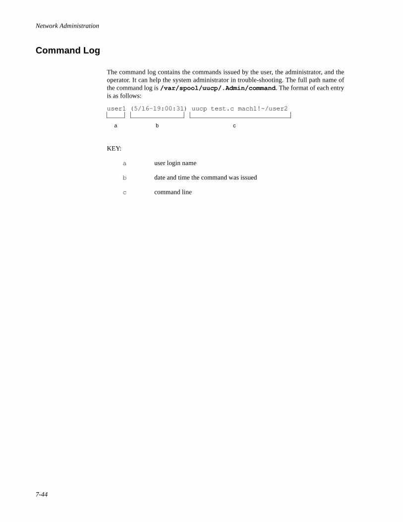
Network Administration
7-44
Command Log 7
The command log contains the commands issued by the user, the administrator, and theoperator. It can help the system administrator in trouble-shooting. The full path name ofthe command log is /var/spool/uucp/.Admin/command . The format of each entryis as follows:
KEY:
a user login name
b date and time the command was issued
c command line
a
user1 (5/16-19:00:31) uucp test.c mach1!~/user2
b c
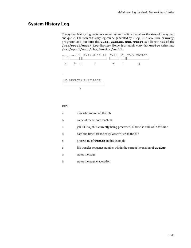
Administering the Basic Networking Utilities
7-45
System History Log 7
The system history log contains a record of each action that alters the state of the systemand queue. The system history log can be generated by uucp , uucico , uux , or uuxqtprograms and put into the uucp , uucico , uux , uuxqt subdirectories of the/var/spool/uucp/.Log directory. Below is a sample entry that uucico writes into/var/spool/uucp/.Log/uucico/mach1 .
.
KEY:
a user who submitted the job
b name of the remote machine
c job ID if a job is currently being processed; otherwise null, as in this line
d date and time that the entry was written to the file
e process ID of uucico in this example
f file transfer sequence number within the current invocation of uucico
g status message
h status message elaboration
uucp mach1 (2/12-8:18:42, 2427, 0) CONN FAILED
a b c d e f g
h
(NO DEVICES AVAILABLE)

Network Administration
7-46
Error Log 7
The error log contains the error messages in the network. Error messages appear in the/var/spool/uucp/.Admin/errors file. When the errors occur, the program aborts.In most cases, this results from file-system problems. A typical entry is as follows:
KEY:
a error type
b program name
c process ID
d date and time that this entry was written to the file
e error message part 1
f error message part 2
g error number
h name of calling module
i line of calling module where the error occurred
a
ASSERT ERROR (uucico) pid: 1513 (5/15-9:03:45) can’t open
b c d e
system 3 (FILE:pkl.c, LINE:356
h if g
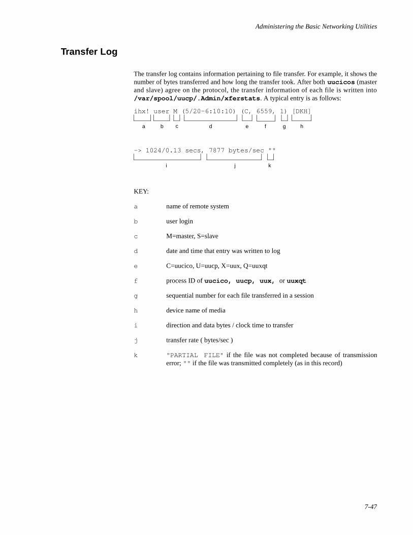
Administering the Basic Networking Utilities
7-47
Transfer Log 7
The transfer log contains information pertaining to file transfer. For example, it shows thenumber of bytes transferred and how long the transfer took. After both uucicos (masterand slave) agree on the protocol, the transfer information of each file is written into/var/spool/uucp/.Admin/xferstats . A typical entry is as follows:
KEY:
a name of remote system
b user login
c M=master, S=slave
d date and time that entry was written to log
e C=uucico, U=uucp, X=uux, Q=uuxqt
f process ID of uucico, uucp, uux, or uuxqt
g sequential number for each file transferred in a session
h device name of media
i direction and data bytes / clock time to transfer
j transfer rate ( bytes/sec )
k "PARTIAL FILE" if the file was not completed because of transmissionerror; "" if the file was transmitted completely (as in this record)
ihx! user M (5/20-6:10:10) (C, 6559, 1) [DKH]
a b c d e gf h
-> 1024/0.13 secs, 7877 bytes/sec ""
i j k
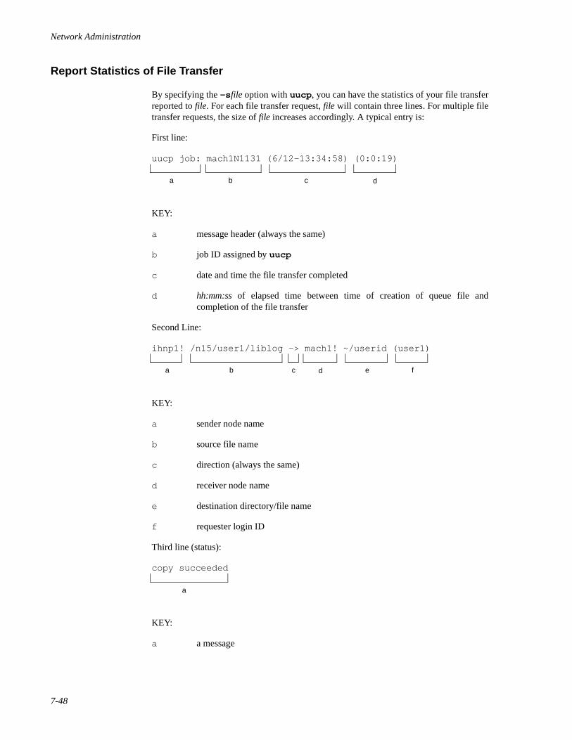
Network Administration
7-48
Report Statistics of File Transfer 7
By specifying the -s file option with uucp , you can have the statistics of your file transferreported to file. For each file transfer request, file will contain three lines. For multiple filetransfer requests, the size of file increases accordingly. A typical entry is:
First line:
uucp job: mach1N1131 (6/12-13:34:58) (0:0:19)
KEY:
a message header (always the same)
b job ID assigned by uucp
c date and time the file transfer completed
d hh:mm:ss of elapsed time between time of creation of queue file andcompletion of the file transfer
Second Line:
ihnp1! /n15/user1/liblog -> mach1! ~/userid (user1)
KEY:
a sender node name
b source file name
c direction (always the same)
d receiver node name
e destination directory/file name
f requester login ID
Third line (status):
copy succeeded
KEY:
a a message
a b c d
a b fedc
a
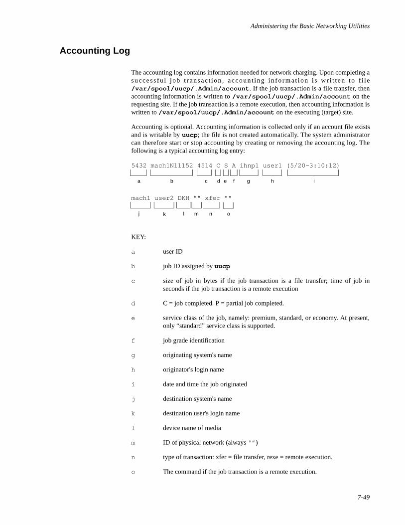
Administering the Basic Networking Utilities
7-49
Accounting Log 7
The accounting log contains information needed for network charging. Upon completing asuccess fu l job t ransac t ion , accoun t ing in f o rmat ion i s w r i t ten to f i l e/var/spool/uucp/.Admin/account . If the job transaction is a file transfer, thenaccounting information is written to /var/spool/uucp/.Admin/account on therequesting site. If the job transaction is a remote execution, then accounting information iswritten to /var/spool/uucp/.Admin/account on the executing (target) site.
Accounting is optional. Accounting information is collected only if an account file existsand is writable by uucp ; the file is not created automatically. The system administratorcan therefore start or stop accounting by creating or removing the accounting log. Thefollowing is a typical accounting log entry:
5432 mach1N11152 4514 C S A ihnp1 user1 (5/20-3:10:12)
mach1 user2 DKH "" xfer ""
KEY:
a user ID
b job ID assigned by uucp
c size of job in bytes if the job transaction is a file transfer; time of job inseconds if the job transaction is a remote execution
d C = job completed. P = partial job completed.
e service class of the job, namely: premium, standard, or economy. At present,only “standard” service class is supported.
f job grade identification
g originating system's name
h originator's login name
i date and time the job originated
j destination system's name
k destination user's login name
l device name of media
m ID of physical network (always “” )
n type of transaction: xfer = file transfer, rexe = remote execution.
o The command if the job transaction is a remote execution.
a b fedc g h i
j k nml o
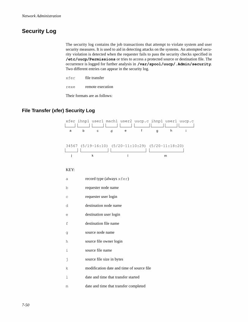
Network Administration
7-50
Security Log 7
The security log contains the job transactions that attempt to violate system and usersecurity measures. It is used to aid in detecting attacks on the systems. An attempted secu-rity violation is detected when the requester fails to pass the security checks specified in/etc/uucp/Permissions or tries to access a protected source or destination file. Theoccurrence is logged for further analysis in /var/spool/uucp/.Admin/security .Two different entries can appear in the security log.
xfer file transfer
rexe remote execution
Their formats are as follows:
File Transfer (xfer) Security Log 7
xfer ihnp1 user1 mach1 user2 uucp.c ihnp1 user1 uucp.c
34567 (5/19-16:10) (5/20-11:10:29) (5/20-11:18:20)
KEY:
a record type (always xfer )
b requester node name
c requester user login
d destination node name
e destination user login
f destination file name
g source node name
h source file owner login
i source file name
j source file size in bytes
k modification date and time of source file
l date and time that transfer started
m date and time that transfer completed
a b fedc g h i
j k l m
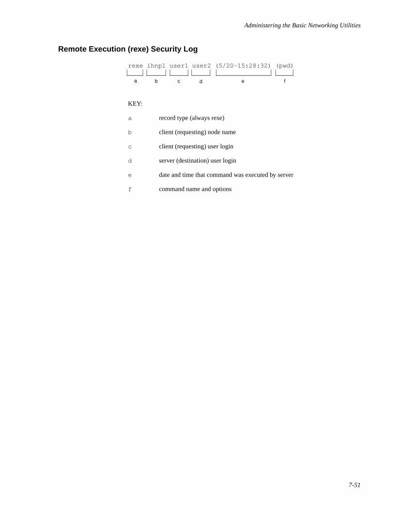
Administering the Basic Networking Utilities
7-51
Remote Execution (rexe) Security Log 7
rexe ihnp1 user1 user2 (5/20-15:28:32) (pwd)
KEY:
a record type (always rexe)
b client (requesting) node name
c client (requesting) user login
d server (destination) user login
e date and time that command was executed by server
f command name and options
a b edc f
Network Administration
7-52
Performance Log 7
The performance log contains statistics about the operation of uucico . uucico writesthe log entries to /var/spool/uucp/.Admin/perflog . Statistics are collected onlyif perflog exists when uucico starts and is writable by uucico . The perflog file isnot created automatically. The system administrator can therefore start or stop thecollection of performance statistics by creating or removing the performance log file, or bymaking it writable or not writable by uucico . In processing terms, if the performance logfile can be opened for writing, logging is performed; if the file cannot be opened forwriting, logging is not performed. In either case, processing continues.
Two types of records are written to the file; each is identified by a mnemonic type at thebeginning of the record. The fields of a record are separated by the “| ” character. Therecord types are:
conn contains statistics about the successful establishment of a connection
xfer contains statistics about a file transfer
NOTE
Fields that are not applicable or unknown are marked by doublequotes ("" ).
Their formats are as follows:

Administering the Basic Networking Utilities
7-53
Connection (conn) Performance Log 7
conn | 860516175047 | 23517 | mach1 | M | ihnp1 | DKH |
d | "" | 20.85 | 3.15 | 0.94
KEY:
a record type (always conn)
b time stamp YYMMDDhhmmss for sorting
c uucico 's process ID
d the name of the machine where the record was written
e M = master, S = slave
f name of remote system
g device name of media
h the protocol that was used for communications
i physical network ID (always "" )
j real time to connect
k user time to connect
l system (kernel) time to connect
a b dc e f g
h i lkj

Network Administration
7-54
File Transfer (xfer) Performance Log 7
xfer | N | 860516175051 | 23517 | mach1 | M | ihnp1 | DKH |
d | "" | ihnp1N2c76 | 118.00 | 121.00 | 1000 | -dc | 0.08 |
0.00 | 0.04 | 0.91 | 0.06 | 0.13 | 0.22 | 0.02 | 0.06 | "" |
KEY:
a record type (always xfer )
b job grade ID
c time stamp (YYMMDDhhmmss) for sorting
d uucico 's process ID
e the name of the machine where the record was written
f M = master, S = slave
g name of remote system
h device name of media
i the protocol that was used for communications
j physical network ID (always "" )
k job ID if master, "" if slave
l time in seconds that job was in queue if master, "" if slave
m turn around time in seconds if master, "" if slave
n size of the file that was actually transferred successfully or partially because oftransmission error
o command line options if master, "" if slave
p real time to start up transfer
q user time to start up transfer
r system (kernel) time to start up transfer
s real time to transfer file
a b edc f g h
i j mlk n o p
q r uts v w x x
Administering the Basic Networking Utilities
7-55
t user time to transfer file
u system (kernel) time to transfer file
v real time to terminate the transfer
w user time to terminate the transfer
x system (kernel) time to terminate the transfer
y "PARTIAL FILE" if the file was not completed because of transmissionerror; "" if the file was transmitted completely (as in this record)
NOTE
Fields that are not applicable or unknown are marked by doublequotes ("" ).
Start-up time includes the time for the master to search the queues for the next job, for themaster and slave to exchange work vectors, and the time to open files.
Transfer time is the time it takes to transfer the data, close the file, and exchangeconfirmation messages.
Termination time is the time it takes to send mail notifications and write status files.
Turnaround time is the difference between the time that the job was queued and the timethat the final notification was sent.
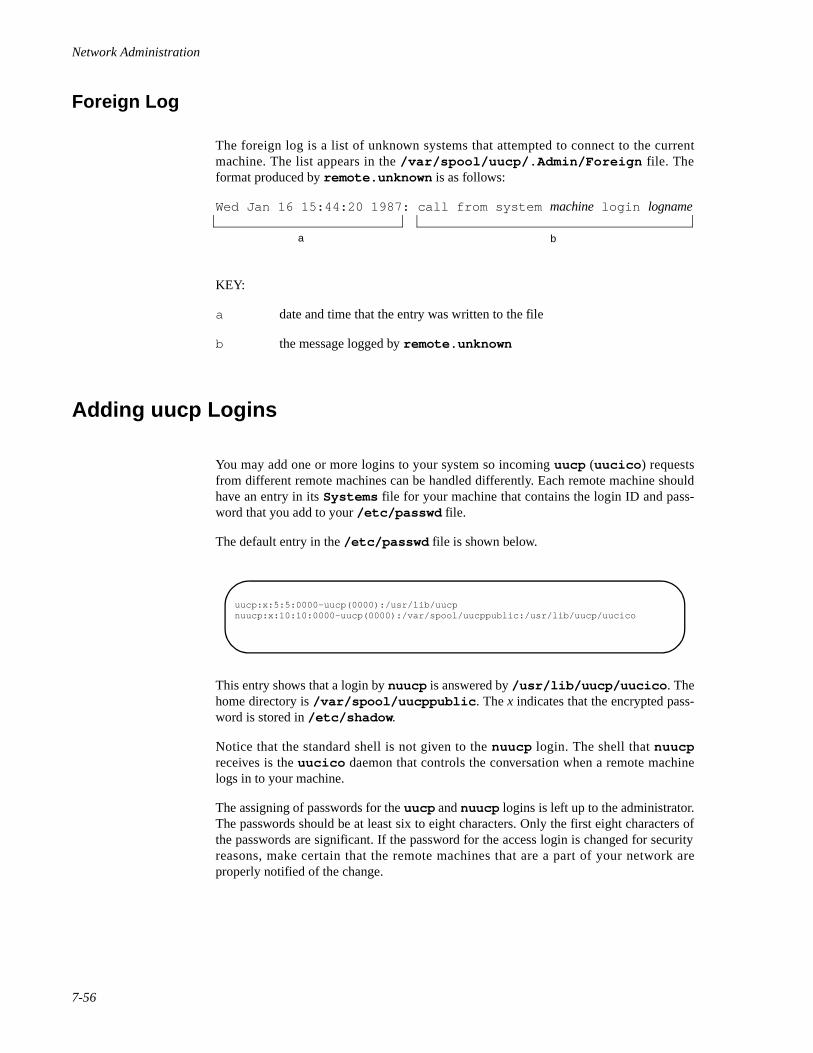
Network Administration
7-56
Foreign Log 7
The foreign log is a list of unknown systems that attempted to connect to the currentmachine. The list appears in the /var/spool/uucp/.Admin/Foreign file. Theformat produced by remote.unknown is as follows:
Wed Jan 16 15:44:20 1987: call from system machine login logname
KEY:
a date and time that the entry was written to the file
b the message logged by remote.unknown
Adding uucp Logins 7
You may add one or more logins to your system so incoming uucp (uucico ) requestsfrom different remote machines can be handled differently. Each remote machine shouldhave an entry in its Systems file for your machine that contains the login ID and pass-word that you add to your /etc/passwd file.
The default entry in the /etc/passwd file is shown below.
This entry shows that a login by nuucp is answered by /usr/lib/uucp/uucico . Thehome directory is /var/spool/uucppublic . The x indicates that the encrypted pass-word is stored in /etc/shadow .
Notice that the standard shell is not given to the nuucp login. The shell that nuucpreceives is the uucico daemon that controls the conversation when a remote machinelogs in to your machine.
The assigning of passwords for the uucp and nuucp logins is left up to the administrator.The passwords should be at least six to eight characters. Only the first eight characters ofthe passwords are significant. If the password for the access login is changed for securityreasons, make certain that the remote machines that are a part of your network areproperly notified of the change.
a b
uucp:x:5:5:0000-uucp(0000):/usr/lib/uucpnuucp:x:10:10:0000-uucp(0000):/var/spool/uucppublic:/usr/lib/uucp/uucico
Administering the Basic Networking Utilities
7-57
NOTE
The uucp login is for local administration only. The passwordshould not be given to remote administrators.
If a login is used to transfer files at multiple levels, those levelsmust be valid login levels for that login.
BNU Setup Procedures 7
This section describes the steps in the BNU setup procedure. These steps fall into threegroups:
• The steps required in every case; see section (1), below.
• The additional steps required if you are using the new CS dialer type (theConnection Server); see sections (2a) and (2b), below.
• The additional steps required if you are not using the new CS dialer type;see sections (3a) and (3b), below.
BNU setup thus always requires the steps in section (1) and, in addition, will require thesteps in either section (2) or section (3).
Sections (2) and (3) are divided into client and server machine subsections; (2a) and (3a)describe client machine administration and (2b) and (3b) describe server machineadministration. Each subsection presents essential steps first, followed by optional orconditional steps.
(1) For All Types of Connection 7
• To use BNU, you must set up the necessary BNU database support files.This is true whether you are using the Connection Server or not. Thefollowing database files must be modified for your system or you mustdetermine that the delivered default files are appropriate. If these files existand were used on your system with a previous release, you may use theexisting files without alteration.
- Sysfiles
- Systems
- Devices
- Dialers
- Devconfig
- Config
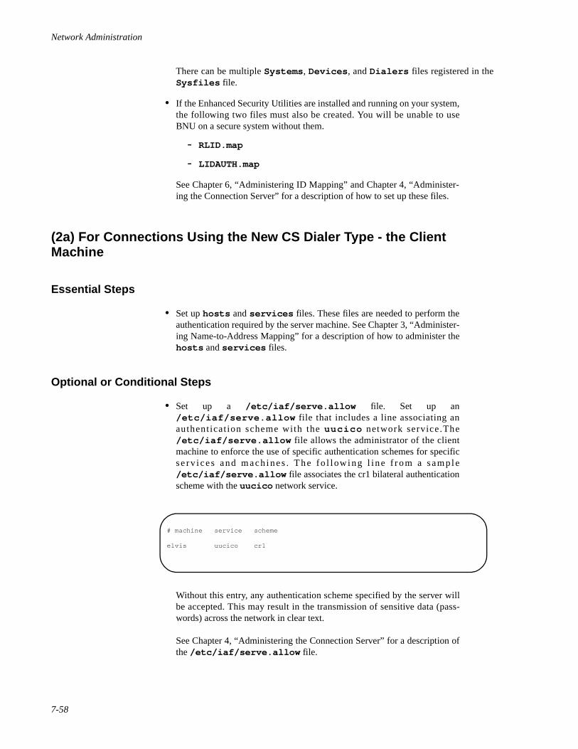
Network Administration
7-58
There can be multiple Systems , Devices , and Dialers files registered in theSysfiles file.
• If the Enhanced Security Utilities are installed and running on your system,the following two files must also be created. You will be unable to useBNU on a secure system without them.
- RLID.map
- LIDAUTH.map
See Chapter 6, “Administering ID Mapping” and Chapter 4, “Administer-ing the Connection Server” for a description of how to set up these files.
(2a) For Connections Using the New CS Dialer Type - the Client Machine 7
Essential Steps 7
• Set up hosts and services files. These files are needed to perform theauthentication required by the server machine. See Chapter 3, “Administer-ing Name-to-Address Mapping” for a description of how to administer thehosts and services files.
Optional or Conditional Steps 7
• Set up a /etc/iaf/serve.allow file. Set up an/etc/iaf/serve.allow file that includes a line associating anauthent icat ion scheme with the uucico network service.The/etc/iaf/serve.allow file allows the administrator of the clientmachine to enforce the use of specific authentication schemes for specificse rv i ces and mach ines . The fo l low ing l ine f r om a sample/etc/iaf/serve.allow file associates the cr1 bilateral authenticationscheme with the uucico network service.
Without this entry, any authentication scheme specified by the server willbe accepted. This may result in the transmission of sensitive data (pass-words) across the network in clear text.
See Chapter 4, “Administering the Connection Server” for a description ofthe /etc/iaf/serve.allow file.
# machine service scheme
elvis uucico cr1
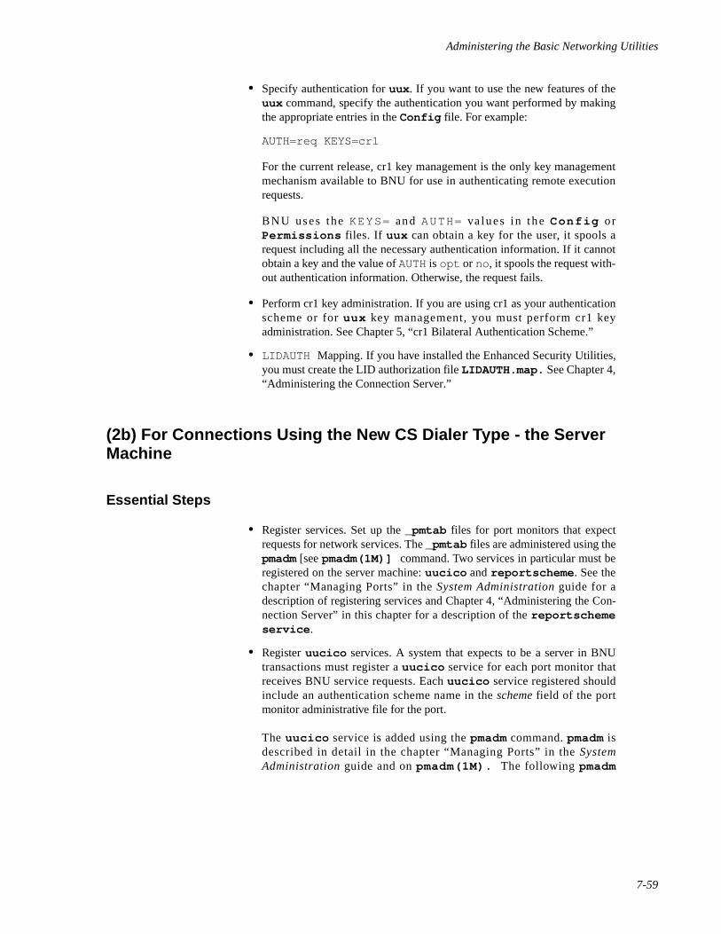
Administering the Basic Networking Utilities
7-59
• Specify authentication for uux . If you want to use the new features of theuux command, specify the authentication you want performed by makingthe appropriate entries in the Config file. For example:
AUTH=req KEYS=cr1
For the current release, cr1 key management is the only key managementmechanism available to BNU for use in authenticating remote executionrequests.
BNU uses the KEYS= and AUTH= va lues in the Conf ig o rPermissions files. If uux can obtain a key for the user, it spools arequest including all the necessary authentication information. If it cannotobtain a key and the value of AUTH is opt or no, it spools the request with-out authentication information. Otherwise, the request fails.
• Perform cr1 key administration. If you are using cr1 as your authenticationscheme or for uux key management, you must perform cr1 keyadministration. See Chapter 5, “cr1 Bilateral Authentication Scheme.”
• LIDAUTH Mapping. If you have installed the Enhanced Security Utilities,you must create the LID authorization file LIDAUTH.map. See Chapter 4,“Administering the Connection Server.”
(2b) For Connections Using the New CS Dialer Type - the Server Machine 7
Essential Steps 7
• Register services. Set up the _pmtab files for port monitors that expectrequests for network services. The _pmtab files are administered using thepmadm [see pmadm(1M)] command. Two services in particular must beregistered on the server machine: uucico and reportscheme . See thechapter “Managing Ports” in the System Administration guide for adescription of registering services and Chapter 4, “Administering the Con-nection Server” in this chapter for a description of the reportschemeservice .
• Register uucico services. A system that expects to be a server in BNUtransactions must register a uucico service for each port monitor thatreceives BNU service requests. Each uucico service registered shouldinclude an authentication scheme name in the scheme field of the portmonitor administrative file for the port.
The uucico service is added using the pmadm command. pmadm isdescribed in detail in the chapter “Managing Ports” in the SystemAdministration guide and on pmadm(1M). The following pmadm
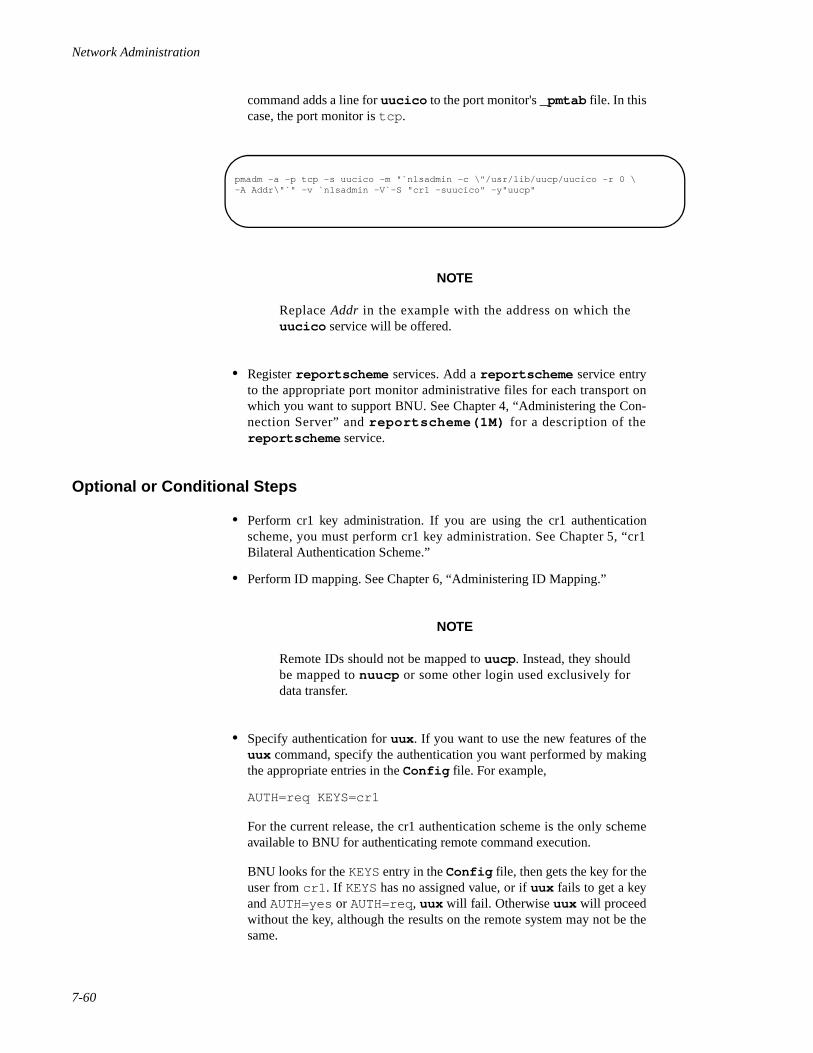
Network Administration
7-60
command adds a line for uucico to the port monitor's _pmtab file. In thiscase, the port monitor is tcp .
NOTE
Replace Addr in the example with the address on which theuucico service will be offered.
• Register reportscheme services. Add a reportscheme service entryto the appropriate port monitor administrative files for each transport onwhich you want to support BNU. See Chapter 4, “Administering the Con-nection Server” and reportscheme(1M) for a description of thereportscheme service.
Optional or Conditional Steps 7
• Perform cr1 key administration. If you are using the cr1 authenticationscheme, you must perform cr1 key administration. See Chapter 5, “cr1Bilateral Authentication Scheme.”
• Perform ID mapping. See Chapter 6, “Administering ID Mapping.”
NOTE
Remote IDs should not be mapped to uucp . Instead, they shouldbe mapped to nuucp or some other login used exclusively fordata transfer.
• Specify authentication for uux . If you want to use the new features of theuux command, specify the authentication you want performed by makingthe appropriate entries in the Config file. For example,
AUTH=req KEYS=cr1
For the current release, the cr1 authentication scheme is the only schemeavailable to BNU for authenticating remote command execution.
BNU looks for the KEYS entry in the Config file, then gets the key for theuser from cr1 . If KEYS has no assigned value, or if uux fails to get a keyand AUTH=yes or AUTH=req, uux will fail. Otherwise uux will proceedwithout the key, although the results on the remote system may not be thesame.
pmadm -a -p tcp -s uucico -m "`nlsadmin -c \"/usr/lib/uucp/uucico -r 0 \-A Addr\"`" -v `nlsadmin -V`-S "cr1 -suucico" -y"uucp"
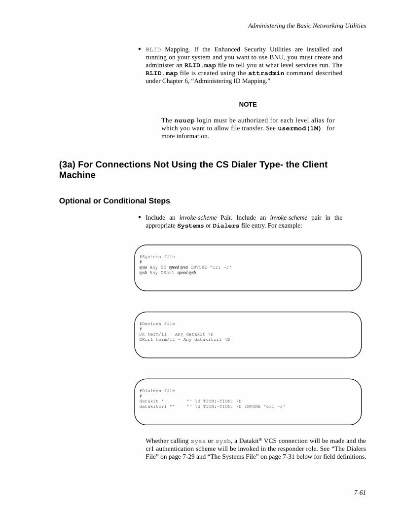
Administering the Basic Networking Utilities
7-61
• RLID Mapping. If the Enhanced Security Utilities are installed andrunning on your system and you want to use BNU, you must create andadminister an RLID.map file to tell you at what level services run. TheRLID.map file is created using the attradmin command describedunder Chapter 6, “Administering ID Mapping.”
NOTE
The nuucp login must be authorized for each level alias forwhich you want to allow file transfer. See usermod(1M) formore information.
(3a) For Connections Not Using the CS Dialer Type- the Client Machine 7
Optional or Conditional Steps 7
• Include an invoke-scheme Pair. Include an invoke-scheme pair in theappropriate Systems or Dialers file entry. For example:
Whether calling sysa or sysb , a Datakit® VCS connection will be made and thecr1 authentication scheme will be invoked in the responder role. See “The DialersFile” on page 7-29 and “The Systems File” on page 7-31 below for field definitions.
#Systems file#sysa Any DK speed sysa INVOKE "cr1 -r"sysb Any DKcr1 speed sysb
#Devices file#DK term/11 - Any datakit \DDKcr1 term/11 - Any datakitcr1 \D
#Dialers file#datakit "" "" \d TION:—TION: \Ddatakitcr1 "" "" \d TION:—TION: \D INVOKE "cr1 -r"
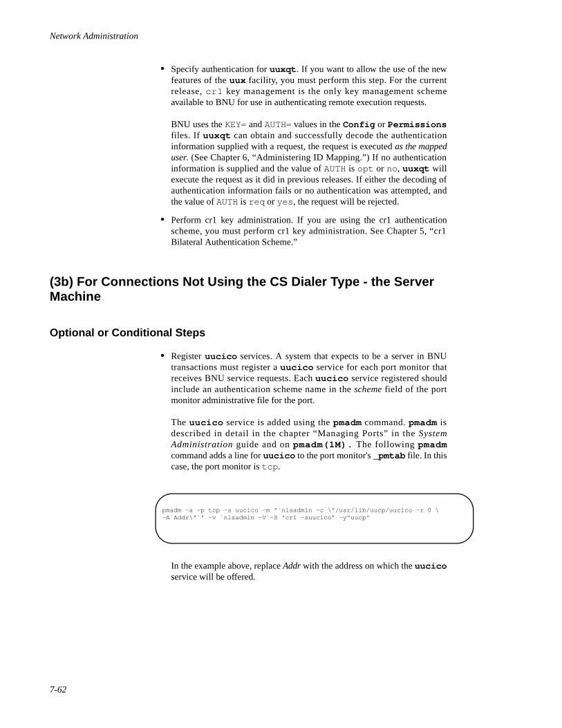
Network Administration
7-62
• Specify authentication for uuxqt . If you want to allow the use of the newfeatures of the uux facility, you must perform this step. For the currentrelease, cr1 key management is the only key management schemeavailable to BNU for use in authenticating remote execution requests.
BNU uses the KEY= and AUTH= values in the Config or Permissionsfiles. If uuxqt can obtain and successfully decode the authenticationinformation supplied with a request, the request is executed as the mappeduser. (See Chapter 6, “Administering ID Mapping.”) If no authenticationinformation is supplied and the value of AUTH is opt or no, uuxqt willexecute the request as it did in previous releases. If either the decoding ofauthentication information fails or no authentication was attempted, andthe value of AUTH is req or yes , the request will be rejected.
• Perform cr1 key administration. If you are using the cr1 authenticationscheme, you must perform cr1 key administration. See Chapter 5, “cr1Bilateral Authentication Scheme.”
(3b) For Connections Not Using the CS Dialer Type - the Server Machine 7
Optional or Conditional Steps 7
• Register uucico services. A system that expects to be a server in BNUtransactions must register a uucico service for each port monitor thatreceives BNU service requests. Each uucico service registered shouldinclude an authentication scheme name in the scheme field of the portmonitor administrative file for the port.
The uucico service is added using the pmadm command. pmadm isdescribed in detail in the chapter “Managing Ports” in the SystemAdministration guide and on pmadm(1M). The following pmadmcommand adds a line for uucico to the port monitor's _pmtab file. In thiscase, the port monitor is tcp .
In the example above, replace Addr with the address on which the uucicoservice will be offered.
pmadm -a -p tcp -s uucico -m "`nlsadmin -c \"/usr/lib/uucp/uucico -r 0 \-A Addr\"`" -v `nlsadmin -V`-S "cr1 -suucico" -y"uucp"
Administering the Basic Networking Utilities
7-63
NOTE
When using cr1 on serial connections, you should configure theport to start on carrier (that is, -c ). This is necessary because theresponder sends no data until the imposer indicates it is ready tostart the protocol. For this reason, autobaud will not work on partsprotected by cr1.
BNU Maintenance 7
Maintenance involves modifying BNU database support files when necessary, trackingtransactions, and cleaning up BNU administrative and log files. Maintenance may be auto-matic or manual.
The following four shell scripts are delivered as part of the BNU software:
uudemon.polluudemon.houruudemon.adminuudemon.clean
These scripts poll remote machines, reschedule transmissions, and clean up old log filesand unsuccessful transmissions. They should be run regularly. Normally, they are runautomatically by cron [see cron(1M)] although they can also be run manually.
Automated Networking Maintenance (cron) 7
BNU is de l ive red w i th en t r ies fo r she l l sc r i p t s i n t he/var/spool/cron/crontabs/uucp file. These entries will automatically handlesome BNU administrative tasks for you. The shell scripts are in /usr/lib/uucp .
The uucp j obs tha t a re s ta r ted by cron shou ld be p laced in the f i l e/var/spool/cron/crontabs/uucp . On a system on which the Enhanced SecurityUtilities are installed and running, the tfadmin database must be updated accordingly souser uucp has the appropriate privileges.
In multi-user state, tasks scheduled by the crontab command are automaticallyperformed by cron. The crontab file for uucp is now used to schedule regular BNUmaintenance using the following shell scripts:
uudemon.poll 7
The uudemon.poll shell script delivered with the system does the following:
• Reads the Poll file (/etc/uucp/Poll ).
Network Administration
7-64
• If any of the machines in the Poll file is scheduled to be polled, places awork file (C.sysnxxxx ) in the /var/spool/uucp/ nodename direc-tory (nodename is the name of the machine being polled).
By default, the shell script is scheduled to run twice an hour, just before uudemon.hour ,so the work files will be there when uudemon.hour is called. The following is thedefault uucp crontab entry for uudemon.poll :
1,30 * * * * $TFADMIN /usr/lib/uucp/uudemon.poll \> /dev/null
uudemon.hour 7
The uudemon.hour shell script delivered with the system does the following:
• Calls the uusched program to search the spool directories for work files(C.files ) that have not been processed and schedules these files fortransfer to a remote machine.
• Calls the uuxqt daemon to search the spool directories for execute files(X.files ) that have been transferred to your computer and were not pro-cessed at the time they were transferred.
The following is the default uucp crontab entry for uudemon.hour :
41,11 * * * * $TFADMIN /usr/lib/uucp/uudemon.hour\> /dev/null
On the system as delivered, uudemon.hour is run twice an hour. You may want it to runmore often if you expect high failure rates.
uudemon.admin 7
The uudemon.admin shell script delivered with the system does the following:
• Runs the uustat command with the -p and -q options. The -q optionreports on the status of work files (C.files ), data files (D.files ), andexecute files (X.files ) that are queued. The -p option prints processinformat ion for networking processes l isted in the lock fi les(/var/spool/locks ).
• Sends the resulting status information to the uucp administrative login viamail [see mail(1) ].
There is no default crontab entry for uudemon.admin . To set up administrativereporting it is recommended that the following line be entered in the uucp crontab file.
48 8,12,16 * * * $TFADMIN /usr/lib/uucp/uudemon.admin\> /dev/null
Administering the Basic Networking Utilities
7-65
uudemon.clean 7
The delivered uudemon.clean shell script does the following:
• Takes log files for individual machines from the/var/spool/uucp/.Log directory, merges them, and places them inthe /var/spool/uucp/.Old directory with other old log information.If log files become large, the ulimit parameter may need to be increased.
• Removes work files (C.files ) seven days old or older, data files(D.files ) seven days old or older, and execute files (X.files ) two daysold or older from the spool directory.
• Returns mail that cannot be delivered to the sender.
• Mails a summary of the status information gathered during the current dayto the uucp administrative login.
The following is the default uucp crontab entry for uudemon.clean:
45 23 * * * $ TFADMIN /usr/lib/uucp/uudemon.clean\> /dev/null 2>&1
uudemon.clean is described in detail in “Cleaning Up Log Files” on page 7-65.
NOTE
If your system handles a heavy uucp load, it may be necessary torun uudemon.clean with an increased ulimit . For example:
45 23 * * * ulimit 5000; $TFADMIN /usr/bin/su uucp -c \"/usr/lib/uucp/uudemon.clean" > /dev/null 2>&1
Manual Maintenance 7
Some files may grow indirectly from uucp and other Basic Networking activities. Thefollowing file should be checked and deleted if it has become too large:
/usr/lib/cron/log This file is a log of cron activities. While it grows withuse, it is automatically truncated when the system goes tothe multi-user state.
Cleaning Up Log Files 7
uudemon.clean is a shell script that should be invoked daily by cron to clean upuucp 's spool directory and to consolidate and dispose of the log files that currently existfor uucp . Currently, uudemon.clean uses two techniques to clean up the log files:
1. The Multi-day (multi) technique. Three days of logs are kept in files calledOld-1, Old-2, and Old-3 . Whenever uudemon.clean is run,
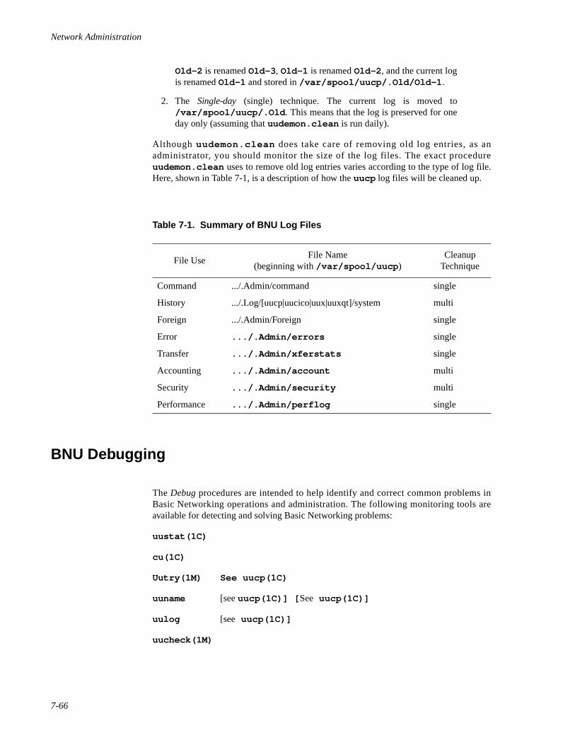
Network Administration
7-66
Old-2 is renamed Old-3 , Old-1 is renamed Old-2 , and the current logis renamed Old-1 and stored in /var/spool/uucp/.Old/Old-1 .
2. The Single-day (single) technique. The current log is moved to/var/spool/uucp/.Old . This means that the log is preserved for oneday only (assuming that uudemon.clean is run daily).
Although uudemon.clean does take care of removing old log entries, as anadministrator, you should monitor the size of the log files. The exact procedureuudemon.clean uses to remove old log entries varies according to the type of log file.Here, shown in Table 7-1, is a description of how the uucp log files will be cleaned up.
BNU Debugging 7
The Debug procedures are intended to help identify and correct common problems inBasic Networking operations and administration. The following monitoring tools areavailable for detecting and solving Basic Networking problems:
uustat(1C)
cu(1C)
Uutry(1M) See uucp(1C)
uuname [see uucp(1C)] [ See uucp(1C)]
uulog [see uucp(1C)]
uucheck(1M)
Table 7-1. Summary of BNU Log Files
File UseFile Name
(beginning with /var/spool/uucp )Cleanup
Technique
Command .../.Admin/command single
History .../.Log/[uucp|uucico|uux|uuxqt]/system multi
Foreign .../.Admin/Foreign single
Error .../.Admin/errors single
Transfer .../.Admin/xferstats single
Accounting .../.Admin/account multi
Security .../.Admin/security multi
Performance .../.Admin/perflog single
Administering the Basic Networking Utilities
7-67
Check Basic Information 7
There are several commands you can use to check for Basic Networking information.
uuname Lists the machines your machine can contact.
uulog Displays the contents of the log directories for particular hosts.
uucheck -v Run to check for the presence of files and directories needed byuucp . uucheck also checks the Permissions fi le andprovides information on the permissions you have set up.
Check for Faulty ACU/Modem 7
You can check if the automatic call units or modems are not working properly in severalways.
• Run uustat -q . This will give counts and reasons for contact failure.
• Run cu -d -l line. This will let you call over a particular communicationsline and print debugging information on the attempt. If the communicationsline, line, is connected to an autodialer, you must add a telephone numberat the end of the command line you execute. Otherwise, line must bedefined as direct in the Devices file.
NOTE
cs must be in debug mode. See Chapter 4, “Administering theConnection Server” for more information.
Check Systems File 7
Check that you have up-to-date information in your systems file if you are having troublecontacting a particular machine. Some things that may be out of date for a machine are its:
• phone number
• login
• password
Debug Transmissions 7
If you cannot contact a machine, check communications to that machine with Uutry anduucp . For a listing of the options accepted by Uutry and uucp , see Uutry(1M) anduucp(1C), respectively.
Network Administration
7-68
Step 1: Simply to try to make contact, run:
/usr/lib/uucp/Uutry -r machine
where machine is replaced with the node name of the machine you are havingproblems contacting. This command will:
1. Start the transfer daemon (uucico ) with debugging. You willget more debugging information if you are root .
2. Direct the debugging output to /tmp/ machine,
3. Print the debugging output to your terminal, using tail -f .When the conversation has completed, the tail -f process iskilled.
You can copy the output from /tmp/ machine if you want to save it.
Step 2: If Uutry doesn't isolate the problem, try to queue a job by running:
uucp -r file machine! /dir/file
where file is replaced by the file you want to transfer, machine is replaced bythe machine you want to copy to, and dir/file is where the file will be placed onthe other machine. The -r option will queue a job but not start the transfer.
Now use Uutry again. If you still cannot solve the problem, you may need tocall support personnel. Save the debugging output; it will help diagnose theproblem.
NOTE
Since the connection phase is now performed by the ConnectionServer, information previously found in /tmp/machine is nowmaintained in the Connection Server debug log (if it is enabled).For more information, see Chapter 4, “Administering the Connec-tion Server.”
8Administering REXEC
Introduction to REXEC Administration . . . . . . . . . . . . . . . . . . . . . . . . . . . . . . . . . . 8-1Overview of REXEC Administration . . . . . . . . . . . . . . . . . . . . . . . . . . . . . . . . . . . . 8-2Registering REXEC with a Port Monitor . . . . . . . . . . . . . . . . . . . . . . . . . . . . . . . . . 8-3Adding and Removing Services . . . . . . . . . . . . . . . . . . . . . . . . . . . . . . . . . . . . . . . . 8-4
Adding a Service . . . . . . . . . . . . . . . . . . . . . . . . . . . . . . . . . . . . . . . . . . . . . . . . 8-4Examples . . . . . . . . . . . . . . . . . . . . . . . . . . . . . . . . . . . . . . . . . . . . . . . . . . . 8-5
Removing a Service . . . . . . . . . . . . . . . . . . . . . . . . . . . . . . . . . . . . . . . . . . . . . . 8-6Example. . . . . . . . . . . . . . . . . . . . . . . . . . . . . . . . . . . . . . . . . . . . . . . . . . . . 8-6
Listing Defined Services . . . . . . . . . . . . . . . . . . . . . . . . . . . . . . . . . . . . . . . . . . . . . . 8-6Linking Services to REXEC . . . . . . . . . . . . . . . . . . . . . . . . . . . . . . . . . . . . . . . . . . . 8-7

Network Administration
8-1
8Chapter 8Administering REXEC
888
Introduction to REXEC Administration 8
Many commercially available transport protocols provide remote execution capabilitiesthat are tied to the protocols. In the OS, the rlogin command, for example, allowsremote users to log into a host on a TCP/IP network. REXEC is a remote execution facilitythat is independent of transport protocol. It allows a user to execute a process on a remotehost, independent of the transport provider.
REXEC increases productivity across a set of machines and makes it possible to shareexpensive hardware on a network. REXEC saves space on a client machine because a copyof an executable file needs to exist only on the server. Hardware can be better utilized byallowing client users to run processes remotely that require the hardware.
REXEC also makes it possible for users to access a centralized database—withoutsignificantly increasing network traffic. If a local user runs a database query on a remotemachine, the remote machine sends only the response to the query across the network.From the user perspective, remote execution of a process through REXEC is transparent.Once the user executes a process on a remote machine, the user interfaces with the processas if it were running locally. However, all files referenced by a remote command arerelative to the server. If a user executes the who command remotely, for example, a list ofusers logged in to the remote machine is displayed, not a list of users on the local machine.
For the system administrator, REXEC makes it possible to administer a set of machinesremotely from a single location, without the overhead of logging in to the remotemachines. REXEC gives administrators the ability
• to monitor the system activity of several machines from a single machine
• to stop and start network applications, such as NFS
• to tune the performance of a set of machines by specifying that certain pro-cesses are to execute on a less active system.
REXEC is service-based. A server defines services that a client can execute remotely. Bydefault, when REXEC is first installed, a server has the following standard servicesdefined:
rx A service that allows a user on a client to execute a command orshell script on the server.
rl A service that allows a user on a client to log in to the server.
rquery A service that allows a client user to list the services available on aserver for remote execution.
Network Administration
8-2
General instructions for invoking an REXEC service, as well as specific instructions forusing the standard services, appear in User's Guide and on rexec(1) .
Overview of REXEC Administration 8
Although REXEC is independent of other network applications, it utilizes components ofthe Network Applications Architecture, specifically ID Mapping and the Service AccessFacility on the server side, the Connection Server on the client side, and an IAFauthentication scheme on both the server and client. The client also utilizes Name-to-Address Mapping.
This section first describes the components of the Network Applications Architecture thatneed to be administered before you set up REXEC. It then gives an overview of the stepsthat are specifically part of REXEC administration.
Prior to setting up REXEC on the server, you must
1. Install an authentication scheme.
2. Set up ID Mapping.
3. Set up the Connection Server.
The authentication scheme, cr1, will be used to protect the REXEC service fromunauthorized remote access. Setting up the authentication scheme will include the use ofthe cr1 administrative commands to control the key management daemon, and toadminister the key database.
Using the ID Mapping facility, map the logins of users on a client to logins on the server.Before client logins can be mapped, the server logins to which client logins will bemapped must exist on the server system with valid entries in the server's /etc/passwdfile. When this is done, use the ID Mapping administrative commands with a cr1 mappingscheme specification to complete the set up of the facility.
NOTE
Currently, cr1 is the only authentication provided that uses IDMapping. cr1 administration involves setting up and maintainingthe cr1 key database, as described in Chapter 5, “cr1 BilateralAuthentication Scheme.”
Setting up the Connection Server on the server will include the installation of thereportscheme service for each port monitor being used to offer the rexec service.
Before you use REXEC from a client, you must do the following:
1. Set up a host address database.
2. Install the same authentication scheme used on the server to protectREXEC.
Administering REXEC
8-3
3. Set up the Connection Server.
How you set up a host address database depends on your network. Host addresses arestored in any of several databases, depending on the type of network connection the clienthas to the server. If a client can reach a server over a TCP/IP transport, for example, thenthat client should have the server's name and address in its /etc/hosts file. SeeChapter 3, “Administering Name-to-Address Mapping” for information about setting up ahost address database for your network.
Setting up the authentication scheme on the client will include the use of the cr1administration command cryptkey to specify the key to be shared between the serverand the client.
Setting up the Connection Server on the client will include the specification of theauthentication scheme to be used. For example, cr1 needs to be specified in /etc/iaf/serve.allow . This will help ensure enforcement of bilateral authentication.
Instructions for setting up and administering Name-to-Address Mapping, the cr1 BilateralAuthentication Scheme, ID Mapping, and the Connection Server appear in precedingsections of this chapter, and should be consulted for more details.
Once you've set up the network services on which REXEC depends, you're ready to set upREXEC itself. Administering the REXEC facility on a server involves the following tasks:
1. Registering REXEC with a port monitor under the Service Access Facility.
2. Maintaining a database of services available for remote execution throughREXEC.
Administering REXEC on a client is just a matter of installing the REXEC software. How-ever, the client administrator may choose to create links from REXEC services to theREXEC command interface to improve the ease with which local users can executeremote services.
The following sections describe REXEC administrative tasks.
Registering REXEC with a Port Monitor 8
As with any service, you must register REXEC with a port monitor under the ServiceAccess Facility (SAF). By registering the service with a port monitor, you associate theservice with a specific port and an authentication scheme. When a client machine attemptsto access the service, it calls the port monitor, which informs the client that the service isprotected by the scheme. If the client supports the scheme, it begins the authenticationprocess.
The authentication scheme authenticates the user on the client machine and maps theuser's login to a local login before REXEC is invoked. REXEC obtains the informationestablished by the authentication scheme and sets up the environment of the mapped userbefore executing the requested service.
Network Administration
8-4
NOTE
As explained earlier, cr1 is the only authentication schemeprovided that uses ID Mapping. It is assumed throughout theREXEC documentation that your authentication scheme is cr1.
To register REXEC with a port monitor and protect it with the cr1 authentication scheme,you must add REXEC to the port monitor's _pmtab file. If the port monitor is tcp , therexec service is added to the _pmtab file by using the command:
pmadm -a -p tcp -s rexec -f u \-m "`nlsadmin -c /usr/lib/rexec/rxserver -p tirdwr`"\-v `nlsadmin -V` -S "cr1 -srexec" -y "remote execution"
The port monitor-specific command, the -m operand, specifies the server rxserver to beexecuted and the module to be pushed on the Stream. rxserver is invoked by a networklistener process after a connection has been established between a client and the server'sport associated with the rexec service, and performs REXEC server functions.
The -S operand of the pmadm command specifies the authentication scheme to beassociated with the service tag rexec .
For more information about registering services under the SAF, see the chapter “ManagingPorts” in the System Administration guide for more information. For additionalinformation about cr1, see Chapter 3, “cr1 Bilateral Authentication Scheme.”
Adding and Removing Services 8
The server administrator controls which local services are available for remote executionby adding and removing services from the REXEC database /etc/rexec/services.
Although REXEC is installed with three standard services defined, these services can beremoved from the REXEC database at any time. In addition, the server administrator canadd other services to the database and make them available to clients for remote execution.
You don't need to edit /etc/rexec/services explicitly; instead, the rxservicecommand is provided as an interface to the file. rxservice allows a privileged user toadd and remove services from the REXEC database.
Adding a Service 8
To make a service on your machine available to remote users through REXEC, you addthe service to the REXEC database, using the rxservice command.
The syntax of the rxservice command, when used to add a service, is as follows:
rxservice -a servicename [ -d description] [ -u ] servicedef
Administering REXEC
8-5
See rxservice(1M) for an explanation of the options accepted by the rxservicecommand.
The REXEC facility defines the following macros, which can be used by any service.When you specify any of the following macros, REXEC substitutes appropriate values forthe macros when a remote user makes a request for the service. The remote user is notrequired to enter the information as arguments to the invoking command.
%m The address of the client machine.
%t The name of the transport provider used to connect to the server.
%s The mapped user's shell, obtained from the /etc/passwd file on the server.
If the value of a macro cannot be obtained, the macro is expanded to a dash (- ).
Examples 8
Assume you want to define the shutdown command so that it can be used remotely. Thesyntax of shutdown is as follows:
shutdown [ -y ] [ -g grace_period] [ -i init_state]
Let's call the remote shutdown service rshutdown. If you want rshutdown to supportall the parameters to shutdown and in the same way (as options), then you would definershutdown as follows:
rxservice -a rshutdown -d "rshutdown usage: rshutdown \ shutdown_options" 'cd /;/sbin/shutdown %*'
The macro %* means that rshutdown supports all options to shutdown. Suppose youwere to define the rshutdown service as follows:
rxservice -a rshutdown -d "rshutdown usage: rshutdown \ minutes initstate" 'cd /;/sbin/shutdown -g %1 -i %2'
When defined this way, the macros indicate that the -g and -i operands (that is, valuesfor %1 and %2, respectively) are required. If the remote user fails to supply a grace periodoperand or an init state operand, the rshutdown command will fail. Note that the servicedefinition omits the -y option. Because the option has been omitted in the servicedefinition, the rshutdown user cannot by-pass the prompt that asks him or her to confirmthat the system should be shut down.
The following command line defines a service called rlookup, which accesses a localdatabase via a command called dblook:
rxservice -a rlookup -d 'Remote database lookup' \ '/usr/bin/dblook %*'
The following command line defines a service called rsetup, which modifies databasetables via a local command called setdb. The setdb command takes the address of theclient machine as a parameter.
rxservice -a rsetup -d 'remote setup service' \ '/usr/bin/setdb %m'
Network Administration
8-6
Removing a Service 8
To disable a service so that it is no longer available for remote execution, you remove theservice from the REXEC database. In addition to providing a means to add services to thedatabase, the rxservice command allows you to remove services.
The syntax of the rxservice command when used to remove a service is
rxservice -r servicename . . .
where servicename can be one or more service names.
Example 8
To remove the services rshutdown, rsetup, and rlookup from the REXEC data-base, enter the following command line:
rxservice -r rshutdown rsetup rlookup
NOTE
If you want to remove a service temporarily, you can remove theservice's execute permissions.
Listing Defined Services 8
As a system administrator, you may need to view the contents of /etc/rexec/services from time to time, to remind yourself which services you have made availablefor remote execution. To display the services file, enter the rxservice commandwith the -l option, as follows:
rxservice -l
In addition to providing an option to rxservice that allows the administrator to display/etc/rexec/services, REXEC installs a command on the server that allows aremote user to display the file. When a remote user displays the file, however, only theservices available to that user are displayed.
The command on the server that allows remote users to display the services file is therxlist command. Remote users use the standard REXEC service rquery to runrxlist remotely.
If the rxlist command is removed from the server, client users cannot determine whichservices are available to them for remote execution; however, they can still invoke thoseservices, provided they already know the names of the services and have appropriatepermissions.
Instructions for using rquery appear in User's Guide and on rexec(1) .

Administering REXEC
8-7
Linking Services to REXEC 8
Administration of REXEC on a client machine is simply a matter of installing the REXECsoftware.
You may choose, however, to create links from the rexec command to the REXECservices defined on a remote machine. The rexec command is the user interface to theREXEC facility. When you link services to rexec, your users can enter abbreviatedcommands to invoke a remote service.
The standard REXEC services are linked to the rexec command by default when thesoftware is installed. If a user wants to run rquery on a server named sftig, forexample, the user enters
rquery sftig
With the link removed, the user enters
rexec sftig rquery
For information about creating and removing hard or symbolic links, see ln(1) .

Network Administration
8-8

-9
2Part 2Mail Service Administration
Replace with Part 2 tab

Network Administration
-10
9Administering the Mail Service
Introduction to Mail Service Administration. . . . . . . . . . . . . . . . . . . . . . . . . . . . . . . 9-1Multilevel Mail Files . . . . . . . . . . . . . . . . . . . . . . . . . . . . . . . . . . . . . . . . . . . . . . . . . 9-1Mail Administration Files . . . . . . . . . . . . . . . . . . . . . . . . . . . . . . . . . . . . . . . . . . . . . 9-2
Editing Mail Administration Files in a Secure Environment . . . . . . . . . . . . . . . 9-2Mail Addressing Styles . . . . . . . . . . . . . . . . . . . . . . . . . . . . . . . . . . . . . . . . . . . 9-3
Establishing a Smarter Host . . . . . . . . . . . . . . . . . . . . . . . . . . . . . . . . . . . . . . . . . . . 9-3Establishing Domain Addresses . . . . . . . . . . . . . . . . . . . . . . . . . . . . . . . . . . . . . . . . 9-4Establishing a Mail Cluster or Gateway . . . . . . . . . . . . . . . . . . . . . . . . . . . . . . . . . . 9-4Establishing Mail Service on a Networked File System . . . . . . . . . . . . . . . . . . . . . . 9-5Administering alias Lists . . . . . . . . . . . . . . . . . . . . . . . . . . . . . . . . . . . . . . . . . . . . . . 9-6NIS and Mail Aliases. . . . . . . . . . . . . . . . . . . . . . . . . . . . . . . . . . . . . . . . . . . . . . . . . 9-7Surrogate Files. . . . . . . . . . . . . . . . . . . . . . . . . . . . . . . . . . . . . . . . . . . . . . . . . . . . . . 9-7
Logging Mail . . . . . . . . . . . . . . . . . . . . . . . . . . . . . . . . . . . . . . . . . . . . . . . . . . . 9-7Using pathrouter for Smart Routing. . . . . . . . . . . . . . . . . . . . . . . . . . . . . . . . . . 9-8Controlling Mail Resource Access. . . . . . . . . . . . . . . . . . . . . . . . . . . . . . . . . . . 9-8
Administering SMTP. . . . . . . . . . . . . . . . . . . . . . . . . . . . . . . . . . . . . . . . . . . . . . . . . 9-9Setting Up SMTP to Listen Over Multiple Networks . . . . . . . . . . . . . . . . . . . . 9-10
The mailR Language and Header Rewriting . . . . . . . . . . . . . . . . . . . . . . . . . . . . . . . 9-11The localmail Command . . . . . . . . . . . . . . . . . . . . . . . . . . . . . . . . . . . . . . . . . . . . . . 9-14MIME, Metamail, and /etc/mail/mailcap . . . . . . . . . . . . . . . . . . . . . . . . . . . . . . . . . 9-15Locales and Character Sets . . . . . . . . . . . . . . . . . . . . . . . . . . . . . . . . . . . . . . . . . . . . 9-17

Network Administration
9-1
9Chapter 9Administering the Mail Service
999
Introduction to Mail Service Administration 9
NOTE
If your system is being run in compliance with the security criteriadescribed in the chapter “Trusted Facility Management” in theguide System Administration, the mail software will be used onlyto provide electronic communication between users on the samecomputer; none of the networking facilities described in thischapter should be made available on such systems.
The mail service provides electronic communications between users on the samecomputer, or between computers connected together on a network, and supports twoaddressing schemes, known as “bang” style and “domain” style. You do not need to doanything for mail to work in the default manner.
You can take advantage of various options within the mail service that enable you to set upa smarter host, establish a domain name, administer a set of sites so they all send mail withthe same system name, set up the mail directory to be shared across a networked filesystem, such as NFS, fill in alias information, and set up a connection to another site thatuses the Simple Mail Transfer Protocol (SMTP). This chapter provides information onthese options.
This chapter covers mail(1) and smtp(1M) . Sendmail(1M) provides an alternateinter-network mail transport mechanism. Sendmail(1M) is covered in the next chapter
Multilevel Mail Files 9
As an administrator, you should be aware that the mail directory, /var/mail , is aMultilevel Directory (MLD). This should be transparent to a user as long as the directoryremains an MLD. (See “Multilevel Directories” in the chapter “Administering FileSecurity Attributes” in the System Administration guide for further information.) If thereare problems, make sure /var/mail is an MLD of mode 775 , is owned by root , andbelongs to group mail . While in real mode, also check the subdirectories for the samepermissions and ownership.
Network Administration
9-2
Mail Administration Files 9
There are four files that are important to mail administration.
• The surrogate file, /etc/mail/mailsurr , describes how to rewriteaddresses and how to deliver messages through the networks. [Seemailsurr(4) .]
• The configuration file, /etc/mail/mailcnfg , which is optional,permits various per-site options to be established. This file is not deliveredwith the Mail service: you must create it yourself if you want to define yourown options. [See mailcnfg(4) .]
• The master alias path file, /etc/mail/namefiles , by default points toone alias file, /etc/mail/names , and one alias directory, /etc/mail/lists . Further (directories and files may be added to the list.) These filesand directories are used to define name mappings and address lists. [Bothfiles are described on mailalias(1) .]
Note that all files under the directory /etc/mail are installed at the level SYS_PUBLIC.If your mail system has problems, check the levels of the files there (using the ls -zcommand) and make sure they are at SYS_PUBLIC. You can change the levels of the filesusing:
chlvl SYS_PUBLIC file
There are additional administration files that need to be considered if sendmail(1M) isused for delivery of remote mail. Refer to the chapter on “Sendmail”.
Editing Mail Administration Files in a Secure Environment 9
Because the mail administration files must be visible at all security levels, they areinstalled at the level SYS_PUBLIC. They can be edited only when the system is inmaintenance mode, and should be edited using the trusted editor, ed(1) . After editing,the level must be restored on the file using:
chlvl SYS_PUBLIC file
for the mail service to work correctly when the system is brought back to multi-user mode.
For more information, see “Maintenance Mode and the Trusted Systems Programmer”and “Editing System Files” in the chapter “Trusted Facility Management” in the guideSystem Administration.
Note also that the mail and mailalias commands pre-compile the surrogate,configuration, and alias files. Therefore, after editing the surrogate or configuration file(remember to do this in maintenance mode), send a test message using the mailcommand; after editing one of the alias files (again, while in maintenance mode), use themailalias command to access one of the aliases within that alias file. Following this,check the level of the files under /etc/mail to make sure they are at the SYS_PUBLIClevel. If necessary, set the levels using the chlvl command:
Administering the Mail Service
9-3
chlvl SYS_PUBLIC /etc/mail/*
This guarantees the compiled surrogate and alias files are maintained at the proper levels.
Mail Addressing Styles 9
The default surrogate file contains command entries for translating between domain styleaddresses and bang style addresses. Bang style addressing is characterized by exclamationpoints (or “bangs”) within the address and looks like host!user or host1!host2!user.Domain style addressing is characterized by the commercial at sign (@) and looks [email protected] or user@host.
Establishing a Smarter Host 9
Although it is possible to maintain the data files for the UUCP network so the systemknows about hundreds or thousands of other systems that can be contacted, it isimpractical to do so. It is often much easier to set up what is known as a “smarter host,”that is, a reference to a UNIX system where remote mail will be shipped if the mail desti-nation is not known to the local computer. For example, assume you need to send a mailmessage to hosta!tony , but your local computer does not know about hosta . The mailmessage can be automatically routed to the computer worldly , which has a moreextensive list of UUCP connections, if worldly is set up as a smarter host.
This is done in two steps:
1. Add a line to mailcnfg that says
SMARTERHOST=smhost
where smhost is replaced with the name of the smarter system (worldly ).
2. Remove the # character from the line within mailsurr that looks likethis:
#'.+' '!(.+)' 'Translate T=1; R=!%X!\\1'
If you are also using a cluster setup, and the cluster name is the same as the smarter host'sname, there will be problems with the above because mail will subsequently strip off thecluster's name. Such a setup will often happen when many sites share a common /etc/mail/mailcnfg file. For such a setup, instead of using the smarter host surrogate entryshown above, use the commented out entry which looks like this
#'.+' '!(.+)' '< sh -c "if [ then uux -a%R - %X!rmail '(1)'; else uux -a%R - %x!rmail '(1)';fi"'
Now add another entry to /etc/mail/mailcnfg describing the smarter host whichwill be used by the cluster's smarter host, using
x=alternate-smarter-host
Network Administration
9-4
At sites where uname does not match the smarter host name, the mail will be forwarded(using uucp ) to the real smarter host. On the smarter host itself, any addresses which itcannot handle will be sent to the alternate smarter host.
Establishing Domain Addresses 9
As distributed, mail knows about two forms of domain style addresses:
user@host and [email protected]
It does not know about
user@host. domain
A domain name is an internationally recognized and registered name for a set of comput-ers. Commercial entities may be registered under domain names similar to .company-name.COM and educational entities may be registered under domain names similar to.school.EDU.
NOTE
.UUCP is not a true domain name. The high-level domain namesof .COM and .EDU are assigned by a central authority.
A system generally knows how to establish direct connections to other computers withinthe local domain, but you may want to make use of a smarter host to take care of otherdomains.
To establish the local domain name, type
/usr/sbin/domainname domain
where domain is replaced with the domain name, such as .company-name.COM (or what-ever is appropriate) and contains a leading period. (Preceding backslashes are added to anyperiods in the domain name, changing “. ” to “ \. ”, before being passed to the regularexpressions in the surrogate file.)
The domain name is also used by the SMTP router when header files are being rewritteninto RFC 822 format. (See “Administering SMTP” on page 9-9.)
Establishing a Mail Cluster or Gateway 9
With the arrival of inexpensive personal computers, it is often desirable to assign a singlename to a set (or a cluster) of computers by which all the computers in the cluster areknown to external computers, for purposes of mail delivery. For example, a cluster ofcomputers known internally under names such as Xsysa , Xsysb , and Xsysc could be
Administering the Mail Service
9-5
assigned the cluster name of Xsys . Mail sent from any of these computers would beshown as being from Xsys ; that is, the internal names would not be known outside thecluster.
To establish a cluster name, add a line such as the following to mailcnfg :
CLUSTER=extname
where extname is the name by which the computer is known externally (such as Xsys ). Inthe surrogate file, /etc/mail/mailsurr , you can then use %L to refer to the value ofCLUSTER.
Establishing Mail Service on a Networked File System 9
With the arrival of inexpensive Local Area Networking (LAN) and networked file systems(such as NFS), it is often desirable to set up clusters of computers that share file systems.
It is also possible to share /var/mail across the computers.
In you choose to establish a mail cluster with a shared /var/mail you can arrange tohave all users' mailboxes created on only one computer, but accessible from all computers.
As an example, assume you want the systems Xsysa , Xsysb , and Xsysc to share asingle mail directory under Xsysa . In addition, the entire file system for each system ismounted under the names /Xsysa , /Xsysb , and /Xsysc . All users have homedirectories under file systems named /homea , /homeb , and /homec , which are mountedon the corresponding computers.
To establish a shared /var/mail file system, complete the following steps:
1. Make sure /var/mail from Xsysa is advertised.
2. Remove the directory /var/mail/:saved from systems that will nothave a local /var/mail (Xsysb and Xsysc ).
3. Add a line to mailcnfg that says
FAILSAFE=Xsysa
With this specified, mail looks for the presence of /var/mail/:saved . If the directory is not there (an indication that the networkconnection to Xsysa has been lost), mail requeues the file to be deliveredto Xsysa via other means (such as by UUCP or SMTP).
4. Move any mailboxes from /var/mail on Xsysb and Xsysc to Xsysa .(If you don't, the files will be inaccessible.)
5. Mount /var/mail from Xsysa .
6. To allow the notify program to identify where the user is logged on (so itcan notify the user when new mail arrives), create, on all systems, a filenamed /etc/mail/notify.sys with contents similar to the following:
Network Administration
9-6
Xsysa /XsysaXsysb /XsysbXsysc /Xsysc
The first column lists the name of the system; the second gives the path ofthe root file system for each computer.
7. To allow the notify program to handle a network failure, create, on allcomputers, a file named /etc/mail/notify.fsys with contentssimilar to the following:
/homea Xsysa/homeb Xsysb/homec Xsysc
The first column lists a file system name; the second contains the name ofthe system (computer) on which that file system is normally mounted. Ifnotify cannot open the mail file for writing, it looks up the file system inthis list and requeues the file to be delivered to the corresponding systemvia other means (such as by UUCP or SMTP).
Administering alias Lists 9
Before delivering a local mail message, mail looks up the user name to see if the username has been assigned an alias. An alias may reference simply another name or a list ofnames.
The master alias path file (/etc/mail/namefiles ) contains a list of files that mailsearches for aliases. As distributed, this list contains two files, /etc/mail/names and/etc/mail/lists , to be searched for aliases.
If the named alias is found at the beginning of a line within an alias file, the rest of that lineis used as the alias. This may contain a single name or a list of names separated by blankspaces. For example, if you want to set up a group mailing list (such as andy.group )that is to be expanded, add a line similar to the following to the alias file:
andy.group tony paul john ned gary hailey mike
Recursive references are permitted, as in this reference to andy.group within anotheralias:
armida.dept andy.group danielle.group bob.group \lee.group pier.group
Several alias files can be listed in namefiles , which may be kept anywhere on the com-puter. This permits different alias files to be owned by different administrators.
Note the sendmail(1M) does not use the mail(1) alias listed above. Generally, ifsendmail(1M) is used for delivery of remote mail, then the mail(1) alias file(s) canbe disregarded. Refer to the chapter on “Sendmail”.
Administering the Mail Service
9-7
NIS and Mail Aliases 9
NIS support is available for the aliases file /etc/mail/names used by mail(1) . Theadvantage of using NIS is that it eliminates the need for maintaining an alias file on eachsystem in a computer network. Instead it is the only necessary to maintain a single copy ofthe mail aliases file - on the NIS master system.
By using NIS, client systems would only need a small number of host specific aliases.Other aliases would be common throughout the network and can be in the NIS-managedset (which is the set of aliases from the file /etc/mail/names on the NIS mastersystem). The full set of aliases for a client would be the union of the host specific aliasesand the NIS-managed set of aliases.
NIS is enabled on a client, by adding a line beginning with the NIS special token ‘+’ to themail address file (/etc/mail/names ). The token indicates that the NIS-managed set ofmail aliases should be “included” at this point in the aliases file.
Note that this is the only NIS special token supported for mail aliases (and it is onlypossible to include the entire NIS set of mail aliases).
Surrogate Files 9
Logging Mail 9
Occasionally it may be necessary to keep a log of traffic going through the system. Forexample, if you were to write a program called /usr/lib/mail/surrcmd/logmailthat takes three arguments (the names of a log file, a sender, and a recipient), it could logall external mail flowing through the system by using this surrogate entry:
'.+!.+' '.*' '> logmail W=1;B=*; /var/adm/mailtransport\%R' '%n'
Because the path used for surrogate commands includes /usr/lib/mail/surrcmd ,there is no need to use a full path to reference logmail . Another example would be tolog traffic to or from a particular system. In the following example, we're logging trafficfrom our system to system xyz and traffic from abc to our system:
'.*' 'xyz!.+' '> W=1;B=*; logmail /var/adm/mailto-xyz\%R' '%n'
'abc!.+' '.*' '> W=1;B=*; logmail /var/adm/mailfrom-abc\ %R' '%n'
The W=1; indicates that mail should not wait for the logging program to complete beforecontinuing its work. The B=*; indicates that mail should execute a single call tologmail , passing it a list of all recipients to whom mail was delivered.
Network Administration
9-8
Using pathrouter for Smart Routing 9
On many systems, you can find a path translation program that gives the shortest route to agiven system, based on various criteria or a database. An example of this is the path-router program. For example, if you wish to setup a machine to act as a mail gatewaybetween the UUCP zone and the Internet zone, then the pathrouter program can beused to facilitate this. The pathrouter program is used to lookup the route informationfor UUCP and domain addresses. As an alternative to using a smarter host, the path-router program can be invoked as a final step in the mailsurr file:
'.+' '.*[!@].*' 'Translate T=1;B=*; R=|pathrouter -p' '%n'
If you know that the majority of the addresses used on the system will have to betranslated, this statement can also be placed just prior to the invocation lines for the uuxprogram.
The pathrouter program in turn uses the file /etc/uucp/paths to decide how torewrite addresses. For example, the following paths file is an sample of the setup for agateway machine. This example prefixes the destination routes with an exclamation mark(! ) to reduce the number of translations done within the mailsurr file.
The following example is used to rewrite the domain addresses defgmbh.ge and anydomain address based in the uk to be routed via the abcinc machine. The xyzinc.comdomain address is converted to !xyzinc!%s in order to utilize the UUCP transportrather than SMTP.
abcinc !abcinc!%s 0defgmbh.ge !abcinc!defgmbh.ge!%s 0windsor !abcinc!windsor!%s 0xyzinc !xyzinc!%s 0
Note that with this example, you would not have a smarter host defined, and so anyaddresses that are not matched by pathrouter are left unchanged. The SMTP DNSlookup will resolve the address and perform delivery over SMTP, and mail to anyunknown address would be returned.
Controlling Mail Resource Access 9
It is often necessary to control access to commercial services. One method of doing this isto prevent any non-local users from sending mail to the commercial site using the Acceptand Deny commands:
'[^!]+' 'commail!.+' 'Accept''.+' 'commail!.+' 'Deny'
Another method is to use an external program to check the sender's path to see if it is avalid user of the service. For example, the following shell script returns 0 if the sender is avalid system, and 1 otherwise:
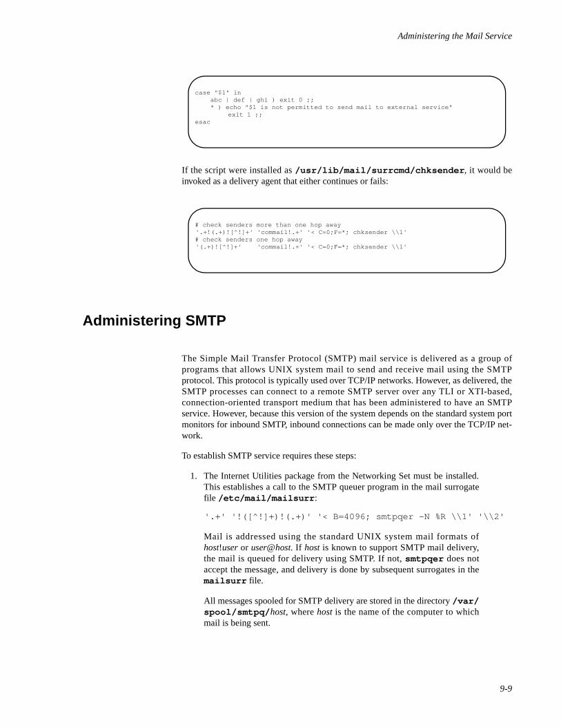
Administering the Mail Service
9-9
If the script were installed as /usr/lib/mail/surrcmd/chksender , it would beinvoked as a delivery agent that either continues or fails:
Administering SMTP 9
The Simple Mail Transfer Protocol (SMTP) mail service is delivered as a group ofprograms that allows UNIX system mail to send and receive mail using the SMTPprotocol. This protocol is typically used over TCP/IP networks. However, as delivered, theSMTP processes can connect to a remote SMTP server over any TLI or XTI-based,connection-oriented transport medium that has been administered to have an SMTPservice. However, because this version of the system depends on the standard system portmonitors for inbound SMTP, inbound connections can be made only over the TCP/IP net-work.
To establish SMTP service requires these steps:
1. The Internet Utilities package from the Networking Set must be installed.This establishes a call to the SMTP queuer program in the mail surrogatefile /etc/mail/mailsurr :
'.+' '!([^!]+)!(.+)' '< B=4096; smtpqer -N %R \\1' '\\2'
Mail is addressed using the standard UNIX system mail formats ofhost!user or user@host. If host is known to support SMTP mail delivery,the mail is queued for delivery using SMTP. If not, smtpqer does notaccept the message, and delivery is done by subsequent surrogates in themailsurr file.
All messages spooled for SMTP delivery are stored in the directory /var/spool/smtpq/ host, where host is the name of the computer to whichmail is being sent.
case "$1" in abc | def | ghi ) exit 0 ;; * ) echo "$1 is not permitted to send mail to external service"
exit 1 ;;esac
# check senders more than one hop away'.+!(.+)![^!]+' 'commail!.+' '< C=0;F=*; chksender \\1'# check senders one hop away'(.+)![^!]+' 'commail!.+' '< C=0;F=*; chksender \\1'
Network Administration
9-10
2. The list of computers that will accept SMTP mail is determined byquerying netdir_getbyname() . See netdir_getbyname(3N)and netconfig(4) for further information.
3. By default the SMTP daemon program in.smtpd only runs when thereare incoming SMTP service requests. This is invoked by the intd internetport monitor. An entry for the SMTP daemon program will be in the inetdconfiguration file /etc/inet/inetd.config .
Alternately, in.smtpd can be disabled and the SMTP daemon/usr/lib/mail/surrcmd/smtpd can be started when the system isbooted.This version of the daemon is always running and it will wait forincoming SMTP requests when there is nothing to process.
When smtpd receives a piece of mail, it does three things:
- It inserts a valid UNIX system From header line;
- It converts the recipient address to host!user form; and
It hands the message to rmail for delivery.
Note that by default, in.smtpd is invoked with the “r” option. This option isused to prevent smtpd from rewriting the addresses in the “From:”, “To:”’“Cc:” and “Bcc:” from Domain style addressing to UUCP style. If thisconversion is desired, then the “-r” option should be removed.
4. The crontab file for the pseudo-user smtp has the following contents:
25 * * * * /usr/lib/mail/surrcmd/smtploop -B55 1 * * * /usr/lib/mail/surrcmd/smtploop -c -w 1 -r 7
By default, mail that cannot be delivered immediately (as it is sent) isqueued and smtploop repeatedly tries to deliver it at one hour intervals.You can change the interval between delivery attempts by modifying theentry for smtpsched in smtp 's crontab file. The smtp crontabl fileis in /usr/spool/cron/crontabs/smtp.
SMTP logs all SMTP activity, including incoming mail messages, in the log file /var/spool/smtpq/LOG . It is backed up once a day by smtpsched ; the log files forprevious days are located in /var/spool/smtpq/LOG. n, where n specifies the day ofthe week (from 0 to 6). The smtpsched program also returns undeliverable mailmessages. [See smtpsched(1M) in the Command Reference.]
The -N option is used by both the smtpqer and smtp programs. This option preventsthese programs from attempting to query a nameserver for MX records and internetaddresses. If you are using a nameserver, remove the -N option.
Setting Up SMTP to Listen Over Multiple Networks 9
smtpd will listen to any connection-oriented TLI or XTI network that provides the SMTPservice. TLI/XTI networks are specified in /etc/netconfig . For each network that isconnection-oriented, smtpd will use netdir_getbyname(3) to determine if theSMTP service exists for that network. If the service does exist, a port is opened at the
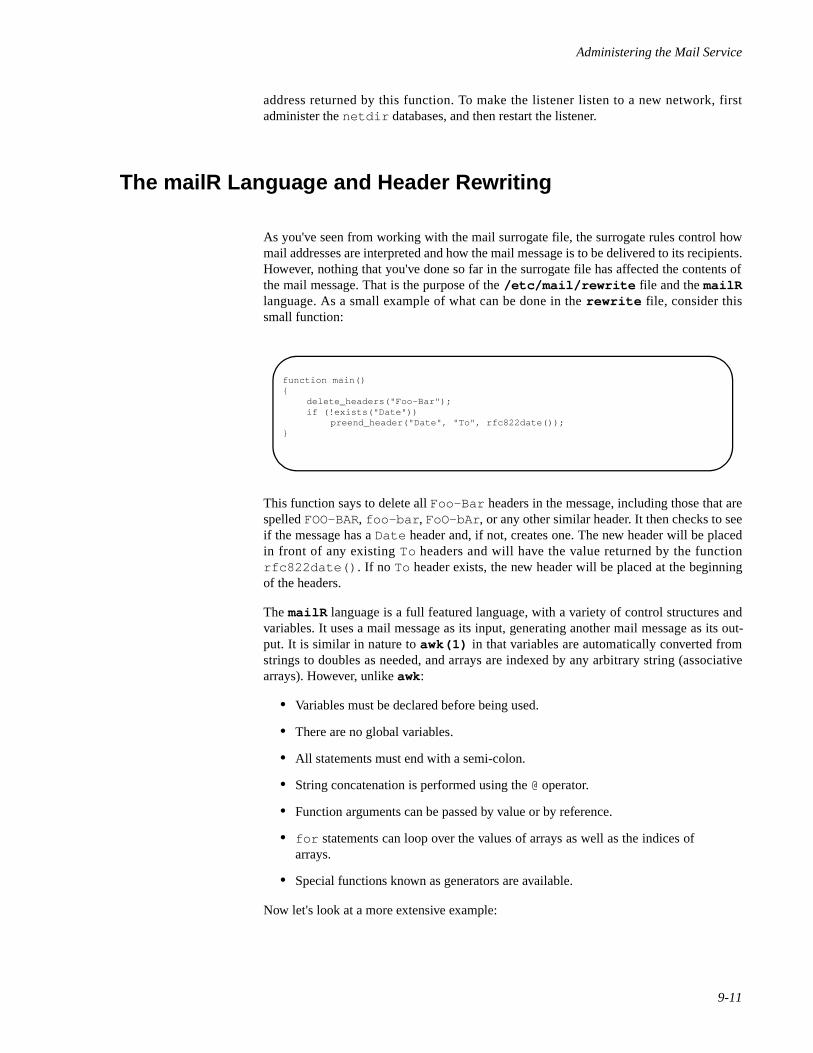
Administering the Mail Service
9-11
address returned by this function. To make the listener listen to a new network, firstadminister the netdir databases, and then restart the listener.
The mailR Language and Header Rewriting 9
As you've seen from working with the mail surrogate file, the surrogate rules control howmail addresses are interpreted and how the mail message is to be delivered to its recipients.However, nothing that you've done so far in the surrogate file has affected the contents ofthe mail message. That is the purpose of the /etc/mail/rewrite file and the mailRlanguage. As a small example of what can be done in the rewrite file, consider thissmall function:
This function says to delete all Foo-Bar headers in the message, including those that arespelled FOO-BAR, foo-bar , FoO-bAr , or any other similar header. It then checks to seeif the message has a Date header and, if not, creates one. The new header will be placedin front of any existing To headers and will have the value returned by the functionrfc822date() . If no To header exists, the new header will be placed at the beginningof the headers.
The mailR language is a full featured language, with a variety of control structures andvariables. It uses a mail message as its input, generating another mail message as its out-put. It is similar in nature to awk(1) in that variables are automatically converted fromstrings to doubles as needed, and arrays are indexed by any arbitrary string (associativearrays). However, unlike awk:
• Variables must be declared before being used.
• There are no global variables.
• All statements must end with a semi-colon.
• String concatenation is performed using the @ operator.
• Function arguments can be passed by value or by reference.
• for statements can loop over the values of arrays as well as the indices ofarrays.
• Special functions known as generators are available.
Now let's look at a more extensive example:
function main(){
delete_headers("Foo-Bar");if (!exists("Date"))
preend_header("Date", "To", rfc822date());}
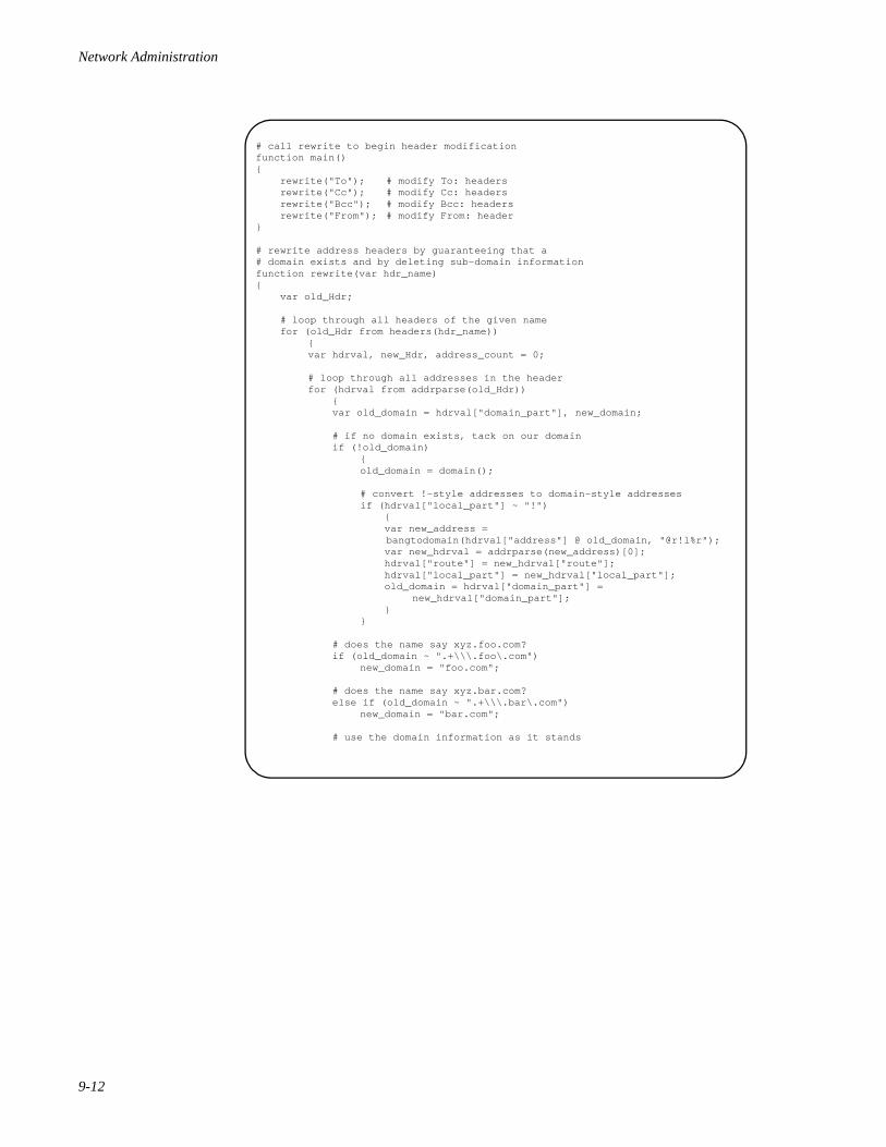
Network Administration
9-12
# call rewrite to begin header modificationfunction main(){ rewrite("To"); # modify To: headers rewrite("Cc"); # modify Cc: headers rewrite("Bcc"); # modify Bcc: headers rewrite("From"); # modify From: header}
# rewrite address headers by guaranteeing that a# domain exists and by deleting sub-domain informationfunction rewrite(var hdr_name){ var old_Hdr;
# loop through all headers of the given name for (old_Hdr from headers(hdr_name))
{var hdrval, new_Hdr, address_count = 0;
# loop through all addresses in the headerfor (hdrval from addrparse(old_Hdr)) { var old_domain = hdrval["domain_part"], new_domain;
# if no domain exists, tack on our domain if (!old_domain)
{old_domain = domain();
# convert !-style addresses to domain-style addressesif (hdrval["local_part"] ~ "!") { var new_address =
bangtodomain(hdrval["address"] @ old_domain, "@r!l%r"); var new_hdrval = addrparse(new_address)[0]; hdrval["route"] = new_hdrval["route"]; hdrval["local_part"] = new_hdrval["local_part"]; old_domain = hdrval["domain_part"] =
new_hdrval["domain_part"]; }}
# does the name say xyz.foo.com? if (old_domain ~ ".+\\\.foo\.com")
new_domain = "foo.com";
# does the name say xyz.bar.com? else if (old_domain ~ ".+\\\.bar\.com")
new_domain = "bar.com";
# use the domain information as it stands
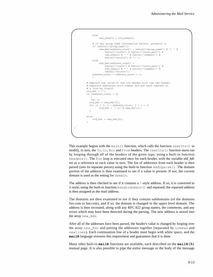
Administering the Mail Service
9-13
This example begins with the main() function, which calls the function rewrite() tomodify, in turn, the To, Cc, Bcc and From headers. The rewrite() function starts outby looping through all of the headers of the given type, using a built-in functionheaders() . The for loop is executed once for each header, with the variable old_hdrset as a reference to each value in turn. The list of addresses from each header is thenparsed (into its separate pieces) using the built-in function addrparse() . The domainportion of the address is then examined to see if a value is present. If not, the currentdomain is used as the setting for domain .
The address is then checked to see if it contains a ! -style address. If so, it is converted to@-style, using the built-in function bangtodomain() and reparsed; the reparsed addressis then assigned as the mail address.
The domains are then examined to see if they contain subdomains (of the domainsfoo.com or bar.com), and if so, the domain is changed to the upper level domain. Theaddress is then recreated, along with any RFC 822 group names, the comments, and anyerrors which may have been detected during the parsing. The new address is stored intothe array new_Hdr .
After all of the addresses have been parsed, the header's value is changed by looping overthe array new_Hdr and putting the addresses together (separated by commas andnewlines ). Each continuation line of a header must begin with white space, and themailR language oversees this requirement and guarantees that it is done.
Many other built-in mailR functions are available, each described on the mailR(5)manual page. It is also possible to pipe the entire message or the body of the message
elsenew_domain = old_domain;
# if any group name information exists, preserve it if (hdrval["group_name"])
new_Hdr[address_count] = hdrval["group_name"] @ ": " @ hdrval["route"] @ hdrval["local_part"] @ new_domain @ " " @ hdrval["comment"] @ hdrval["errors"] @ "; ";
elsenew_Hdr[address_count] = hdrval["route"] @ hdrval["local_part"] @ new_domain @ " " @ hdrval["comment"] @ hdrval["errors"];
address_count = address_count + 1; }
# Replace the value of the old header with the new header.# Separate addresses with commas and put each address on# a line by itself.old_Hdr = "";if (address_count > 0)
{ var j; old_Hdr = new_Hdr[0]; for (j = 1; j < address_count; j = j + 1)
old_Hdr = ",\n" @ new_Hdr[j]; }
else old_Hdr = new_Hdr[0];}
}
Network Administration
9-14
through an external command, instead of only being able to modify the headers of themessage.
The mail command automatically calls the mailR function main() before doing anyparsing of the mail surrogate file. Before the message is delivered to a local mailbox, themailR function local() is invoked. It is also possible to invoke a mailR function justprior to the message being passed to a delivery command. For example, the surrogateentry
'.+' 'xxgate!.+' '< H=rewrite_for_xxgate;B=1024; \uux -a %R -p -- \\1!rmail' '(\\2)'
says to use uux to send the message to the system xxgate , but before doing so,rewrite it according to the mailR function rewrite_for_xxgate() . This mightbe useful in cases where there are special requirements for mail coming into the systemxxgate , such as requiring ! -style addresses in all To headers.
Note that this rewriting does not affect the message as seen by other recipients. Some-times, however, it is necessary to have a message rewritten based on who it is coming fromor going to, but irrespective of the delivery mechanism. This is accomplished using aRewrite surrogate entry, as in
'xxgate!.+' '.+' 'Rewrite rewrite_coming_from_xxgate'
This says that any messages coming from the system xxgate should be rewritten accordingto the mailR function rewrite_coming_from_xxgate() . This might be useful if itis known that messages coming from the system xxgate have certain idiosyncrasies,such as using a special format for encoding attachments within the message.
See the file /etc/mail/rewrite.samples for other examples of mailR functions.
The localmail Command 9
Consider a user population spread across a group of machines (sysa , sysb and sysc )that has a disjoint address space. That is, a given user only has a login on one of themachines and none of the others. For example, if user foo had a login on sysa , the userwould not have a login on sysb or sysc . This normally means that sending mail to a useron one of those machines will require knowing which machine the user resides on. How-ever, it is possible to create a flat name space across the entire set of machines, such thatyou can send mail to user xyz on any of the machines and have the mail go to the user onthe proper machine. This can be done in several different ways:
1. Set up accounts on all machines for all of the users, and establishforwarding files for each user so the mail is sent to the proper machine.This quickly becomes an administrative headache.
2. Create a mailing list that will be placed on each machine which lists theuser and the system that user belongs on. For example, such a mailing listmight read:
usera usera@sysbuserb userb@sysa
Administering the Mail Service
9-15
userc userc@sysbuserd userd@sysc
One advantage of this is that mail to a given user will stay on the machine ifit belongs there, and go to the proper machine if it isn't local. However, thisalso requires that whenever a user is added to any of the systems, themailing list must be updated on all machines.
3. Alternatively, the localmail program may be used. It takes a user nameand looks it up on the system to see if it is to be considered a local username. If it is local, it just prints the user name, but if not, it rewrites the username according the options passed to it.
This makes localmail ideal for use as a translation surrogate. For example, thefollowing surrogate entry could be placed at the end of the surrogate file:
&'.+' '[^!@]+' 'Translate T=1;B=*; R=|localmail -p -S\ @sysa' '%n
Any user names that are not local will be returned with the suffix @sysa added, whichcauses the mail to be forwarded to the system sysa . That single system would then need amaster mailing list as described above which specifies where the user actually lives.
Note that this is similar to how a smarter host is handled. With a smarter host, any remoteaddress that is not recognized is rewritten to go to another host, which presumably knowshow to handle such addresses. In this case as well, user names that are not recognized aslocal user names are rewritten to go to another host, which presumably knows how tohandle such addresses.
If you look at the /etc/mail/mailsurr file, you will find a commented out invoca-tion of localmail .
MIME, Metamail, and /etc/mail/mailcap 9
The mail system supports the Multipurpose Internet Mail Extensions (MIME) standard inseveral ways. The introduction to the MIME standard says:
RFC 822 defines a message representation protocol which specifies considerabledetail about message headers, but which leaves the message content, or messagebody, as flat ASCII text. This document redefines the format of message bodies toallow multi-part textual and non-textual message bodies to be represented andexchanged without loss of information. This is based on earlier work documented inRFC 934 and RFC 1049, but extends and revises that work. Because RFC 822 saidso little about message bodies, this document is largely orthogonal to (rather than arevision of) RFC 822.
In particular, this document is designed to provide facilities to include multipleobjects in a single message, to represent body text in charactersets other than USASCII, to represent formatted multi-font text messages, to represent non-textualmaterial such as images and audio fragments, and generally to facilitate laterextensions defining new types of Internet mail for use by cooperating mail agents.
Network Administration
9-16
MIME is supported by the mail system in several ways:
• When reading a mail message that uses MIME capabilities beyond simpletext, a MIME interpreter known as metamail wil l be invokedautomatically.
• To create a mail message, either mailx or another program, known asmailto , may be used to compose messages which contain enhanced text,or have multiple parts.
• Support for additional message or attachment types, such as audio or visualattachments, is easily administered through the file /etc/mail/mailcap .
As an administrator, you will only have to become involved with MIME if you wish to addsupport for a new mail attachment format. To add support for a new attachment format,you will need to know several things:
• What command can be invoked to create a file of this type?
• What command can be invoked to display a file of this type?
• How would you describe this file type?
• Does the terminal need to be accessed when showing a file of this type?
As an example, consider the attachment format known as message/external-body. This is aspecial type of attachment which actually refers to a file found on some other system oracross an Internet link. To create one, you would use the command extcompose with asingle argument, which specifies where to put the output. This command generates theoutput as a series of headers followed by a body which gives additional informationneeded by some external access methods. This is specified in the mailcap file by anentry which says
composetyped = extcompose %s;
The keyword composetyped indicates that headers are output as well as a body. If therewere no headers in the output, the keyword compose would be used instead. The %sindicates where to put the output and will be filled in with a filename.
To display a message/external-body, you would invoke the showexternal program,passing in various parameters found on the Content-type header of such a message.This is the first field of the mailcap entry for message/external-body and would bespecified by
showexternal %s %{access-type} %{name} %{site}\%{directory} %{mode} %{server};
This program interacts with the user, so a terminal is needed. This requires that the needs-terminal keyword be specified.
We can call this type of attachment “Reference to data in external location.” This would bespecified as part of a label field.
Administering the Mail Service
9-17
Putting this together produces a mailcap entry which looks like this:
message/external-body; showexternal %s %{access-type}\ %{name} %{site} %{directory} %{mode} %{server}; \ needsterminal; composetyped = extcompose %s; \ description="Reference to data in external location"
As you can see, each field is separated by a semi-colon, and continuation lines are speci-fied by putting a backslash at the end of each line. A complete description of themailcap file can be found in mailcap(4).
Locales and Character Sets 9
MIME requires access to a character set name to describe the character set used by thedifferent locales being used on the system. For example, the locale german wouldtypically use the character set iso8859-1 .
When showing a message created with the character set iso8859-1 , the mail programwill check the character set against your current character set and, if they don't match,lodge a complaint.
The character set in use by a user can be specified by setting the environment variableMM_CHARSET to the correct value. However, this requires that the user be informed aboutyet another environment variable (in addition to the LOCALE environment variable).
Eventually, the system incorporates character set information in the locale-specific systemfiles. Until that time, however, character set information may be made available through afile named /etc/mail/charset/ locale, which may be created by the administratorfor each locale in use on the system.
These files each have a single line, which specifies the character set for that locale. Forexample, the file /etc/mail/charset/german would contain the single line whichsays iso8859-1 .

Network Administration
9-18

10Sendmail
Introduction to Sendmail . . . . . . . . . . . . . . . . . . . . . . . . . . . . . . . . . . . . . . . . . . . . . . 10-1Mail vs. Sendmail . . . . . . . . . . . . . . . . . . . . . . . . . . . . . . . . . . . . . . . . . . . . . . . . . . . 10-1Sendmail Aliases . . . . . . . . . . . . . . . . . . . . . . . . . . . . . . . . . . . . . . . . . . . . . . . . . . . . 10-1
Rebuilding the Sendmail Alias Database . . . . . . . . . . . . . . . . . . . . . . . . . . . . . . 10-2NIS and Sendmail Aliases . . . . . . . . . . . . . . . . . . . . . . . . . . . . . . . . . . . . . . . . . 10-2Pre-User Forwarding . . . . . . . . . . . . . . . . . . . . . . . . . . . . . . . . . . . . . . . . . . . . . 10-3
Sendmail Configuration File . . . . . . . . . . . . . . . . . . . . . . . . . . . . . . . . . . . . . . . . . . . 10-3Configuration File Syntax and Semantics . . . . . . . . . . . . . . . . . . . . . . . . . . . . . . . . . 10-3The Syntax. . . . . . . . . . . . . . . . . . . . . . . . . . . . . . . . . . . . . . . . . . . . . . . . . . . . . . . . . 10-3
R and S - Rewriting Rules . . . . . . . . . . . . . . . . . . . . . . . . . . . . . . . . . . . . . . . . . 10-4D - Define Macro . . . . . . . . . . . . . . . . . . . . . . . . . . . . . . . . . . . . . . . . . . . . . . . . 10-4C and F - Define Classes . . . . . . . . . . . . . . . . . . . . . . . . . . . . . . . . . . . . . . . . . . 10-4M - Define Mailer. . . . . . . . . . . . . . . . . . . . . . . . . . . . . . . . . . . . . . . . . . . . . . . . 10-5H - Define Header . . . . . . . . . . . . . . . . . . . . . . . . . . . . . . . . . . . . . . . . . . . . . . . 10-5O - Set Option. . . . . . . . . . . . . . . . . . . . . . . . . . . . . . . . . . . . . . . . . . . . . . . . . . . 10-6T - Define Trusted Users . . . . . . . . . . . . . . . . . . . . . . . . . . . . . . . . . . . . . . . . . . 10-6Precedence Definitions . . . . . . . . . . . . . . . . . . . . . . . . . . . . . . . . . . . . . . . . . . . . 10-6
The Semantics . . . . . . . . . . . . . . . . . . . . . . . . . . . . . . . . . . . . . . . . . . . . . . . . . . . . . . 10-6Special Macros, Conditionals. . . . . . . . . . . . . . . . . . . . . . . . . . . . . . . . . . . . . . . 10-7Special Classes . . . . . . . . . . . . . . . . . . . . . . . . . . . . . . . . . . . . . . . . . . . . . . . . . . 10-8
The Left Hand Side . . . . . . . . . . . . . . . . . . . . . . . . . . . . . . . . . . . . . . . . . . . 10-9The Right Hand Side . . . . . . . . . . . . . . . . . . . . . . . . . . . . . . . . . . . . . . . . . . 10-9
Semantics Of Rewriting Rule Sets . . . . . . . . . . . . . . . . . . . . . . . . . . . . . . . . . . . 10-10Mailer Flags etc . . . . . . . . . . . . . . . . . . . . . . . . . . . . . . . . . . . . . . . . . . . . . . . . . 10-11The error Mailer . . . . . . . . . . . . . . . . . . . . . . . . . . . . . . . . . . . . . . . . . . . . . . . . . 10-12
Building a Configuration File . . . . . . . . . . . . . . . . . . . . . . . . . . . . . . . . . . . . . . . . . . 10-13Purpose . . . . . . . . . . . . . . . . . . . . . . . . . . . . . . . . . . . . . . . . . . . . . . . . . . . . . . . . 10-13Philosophy . . . . . . . . . . . . . . . . . . . . . . . . . . . . . . . . . . . . . . . . . . . . . . . . . . . . . 10-13
Large Site, Many Hosts - Minimum Information . . . . . . . . . . . . . . . . . . . . 10-13Small Site - Complete Information . . . . . . . . . . . . . . . . . . . . . . . . . . . . . . . 10-14Single Host . . . . . . . . . . . . . . . . . . . . . . . . . . . . . . . . . . . . . . . . . . . . . . . . . 10-14
Relevant Issues . . . . . . . . . . . . . . . . . . . . . . . . . . . . . . . . . . . . . . . . . . . . . . . . . . 10-14How To Proceed . . . . . . . . . . . . . . . . . . . . . . . . . . . . . . . . . . . . . . . . . . . . . . . . . 10-15Testing The Rewriting Rules - The -bt Flag . . . . . . . . . . . . . . . . . . . . . . . . . . . . 10-15Building Mailer Descriptions . . . . . . . . . . . . . . . . . . . . . . . . . . . . . . . . . . . . . . . 10-16
Enabling Sendmail. . . . . . . . . . . . . . . . . . . . . . . . . . . . . . . . . . . . . . . . . . . . . . . . . . . 10-18Sendmail Utilities . . . . . . . . . . . . . . . . . . . . . . . . . . . . . . . . . . . . . . . . . . . . . . . . . . . 10-18Sendmail Mail Queue . . . . . . . . . . . . . . . . . . . . . . . . . . . . . . . . . . . . . . . . . . . . . . . . 10-19Sendmail Log. . . . . . . . . . . . . . . . . . . . . . . . . . . . . . . . . . . . . . . . . . . . . . . . . . . . . . . 10-19

Network Administration
10-1
10Chapter 10Sendmail
101010
Introduction to Sendmail 10
As an alternative to mail (and uucp), sendmail(1M) may be used to send or receiveremote mail from hosts connected via a network.
Sendmail(1M) was designed as a centralized mail facility used to route mail byinterpreting addresses according to a set of well-defined (and configurable) rules. Messageheaders can also be rewritten to conform to a number of standards or specialized targets.
Sendmail(1M) does not interface directly with users nor does actual mail delivery.Rather, it collects mail messages generated by such mail interface programs as mail(1)or mailx(1) , edits the message as directed and then calls the appropriate mailer to dothe mail delivery.
There is also a sendmail daemon that can be invoked as an SMTP server for incomingremote mail.
Mail vs. Sendmail 10
Usually, the option for processing remote mail will come down to either mail (i.e. smtp )or sendmail. From a basic functional standpoint both facilities are similar. Often thedecision will be based on the environment that the system will be in. For example, it mightbe desirable to choose the mail facility that is used by the majority of the local hosts withinthe network.
Sendmail Aliases 10
The sendmail alias database exists in two forms. One in a text form, maintained in the file/etc/ucbmail/aliases (there is also a soft link at /usr/ucblib/aliases ).
Aliases are of the form:
alias: recipient1, recipient2, ...
Aliases may be continued by starting any continuation lines with a space or tab. Blanklines and lines beginning with a sharp sign (“#”) are comments.
Network Administration
10-2
Note that aliases are case-insensitive. As an example, if the alias file contained the line:
fred: name1, ...
then mail addressed to fred, Fred or FRED would all be delivered according to the abovealias.
This would also mean that if the aliases file has two lines such as:
fred: name1Fred: name2
then only one of these alias entries would be used (generally, the last alias overrides anyprevious alias when there are duplicate names). Note that sendmail(1M) prints awarning when building the aliases database when it detects duplicate alias names.
The second form of the sendmail alias database is processed by the dbm(3N) sub-system. This form is in the files /etc/ucbmail/aliases.dir and /etc/ucbmail/aliases.pag . For performance reasons, this is the form that sendmail actu-ally uses to resolve aliases.
Rebuilding the Sendmail Alias Database 10
The dbm version of the sendmail alias database may be rebuilt by executing the command:
/usr/ucb/newaliases-or-
/usr/ucblib/sendmail -bi
NIS and Sendmail Aliases 10
NIS support is available for the aliases used by sendmail(1M) . The advantage of usingNIS is that it eliminates the need for maintaining an alias file on each system in a computernetwork. Instead, it is only necessary to maintain a single copy of the sendmail aliases - onthe NIS master system.
By using NIS, client systems would only need a small number of host specific aliases.Other aliases would be common throughout the network and can be in the NIS-managedset (which is the set of sendmail aliases from the file /etc/ucbmail/aliases on theNIS master system). The full set of aliases for a client would be the union of the hostspecific aliases and the NIS-managed set of aliases.
NIS is enabled on a client by adding a line beginning with the NIS special token '+' to thesendmail aliases file (/etc/ucbmail/aliases ). The token indicates that the NIS-managed set of sendmail aliases should be “included” at this point in the aliases file.
Note that this is the only NIS special token supported for sendmail aliases (and it is onlypossible to include the entire NIS set of sendmail aliases).
Sendmail
10-3
Pre-User Forwarding 10
As an alternative to the alias database, a user may put a file with the name “.forward” inhis/her home directory. If this file exists, sendmail(1M) redirects mail for that user tothe list of addresses listed in the .forward file.
Sendmail Configuration File 10
Sendmail(1M) is distributed with two configuration files: /etc/ucbmail/main.cfand /etc/ucbmail/subsidiary.cf . One of these files should be installed at/etc/ucbmail/sendmail.cf . The type of configuration will determine which file touse.
If the system will be the master host of the local network then the configuration filemain.cf should be used.
If the system is NOT the master host of the local network then the configuration filesubsidiary.cf should be used (the default).
The configuration file contains header declarations, mailer definitions and addressrewriting rules. The syntax of this file is designed to be easy to parse.
More detail about the syntax of the configuration file provided later in this chapter.
Configuration File Syntax and Semantics 10
This section describes the configuration file in detail, including hints on how to write oneof your own if you have to.
There is one point that should be made clear immediately: the syntax of the configurationfile is designed to be reasonably easy to parse. Since this is done every time sendmailstarts up, it is rather easy for a human to read or write.
An overview of the configuration file is given first, followed by details of the semantics.
The Syntax 10
The configuration file is organized as a series of lines, each of which begins with a singlecharacter defining the semantics for the rest of the line. Lines beginning with a space or atab are continuation lines (although the semantics are not well defined in many places).Blank lines and lines beginning with a sharp symbol `#' are comments.
Network Administration
10-4
R and S - Rewriting Rules 10
The core of address parsing are the rewriting rules. These are an ordered productionsystem. Sendmail scans through the set of rewriting rules looking for a match on the lefthand side (LHS) of the rule. When a rule matches, the address is replaced by the righthand side (RHS) of the rule.
There are several sets of rewriting rules. Some of the rewriting sets are used internally andmust have specific semantics. Other rewriting sets do not have specifically assignedsemantics, and may be referenced by the mailer definitions or by other rewriting sets.
The syntax of these two commands are:
n
Sets the current ruleset being collected to n. If you begin a ruleset more than once itdeletes the old definition.
Rlhs rhs comments
The fields must be separated by at least one tab character; there may be embedded spacesin the fields. The lhs is a pattern that is applied to the input. If it matches, the input isrewritten to the rhs. The comments are ignored.
D - Define Macro 10
Macros are named with a single character. These may be selected from the entire ASCIIset, but user-defined macros should be selected from the set of upper case letters only.Lower case letters and special symbols are used internally.
The syntax for macro definitions is:
Dx val
where x is the name of the macro and val is the value it should have. Macros can beinterpolated in most places using the escape sequence
$x
C and F - Define Classes 10
Classes of words may be defined to match on the left hand side of rewriting rules. Forexample a class of all local names for this site might be created so that attempts to send tooneself can be eliminated. These can either be defined directly in the configuration file orread in from another file. Classes may be given names from the set of upper case letters.Lower case letters and special characters are reserved for system use.
The syntax is:
Sendmail
10-5
Cc word1 word2Fc file[format]
The first form defines the class c to match any of the named words. It is permissible to splitthem among multiple lines; for example, the two forms:
CHmonet ucbmonet
and
CHmonetCHucbmonet
are equivalent. The second form reads the elements of the class c from the
named file; the format is a scanf(3) pattern that should produce a single string.
M - Define Mailer 10
Programs and interfaces to mailers are defined in this line. The format is:
Mname, {field=value}*
where name is the name of the mailer (used internally only) and the “field=name” pairsdefine attributes of the mailer. Fields are:
Path The pathname of the mailerFlags Special flags for this mailerSender A rewriting set for sender addressesRecipient A rewriting set for recipient addressesArgv An argument vector to pass to this mailerEol The end-of-line string for this mailerMaxsize The maximum message length to this mailer
Only the first character of the field name is checked.
H - Define Header 10
The format of the header lines that sendmail inserts into the message are defined by the Hline. The syntax of this line is:
H[?flags]hname:htemplate
Continuation lines in this specification are reflected directly into the outgoing message.The htemplate is a macro expanded before insertion into the message. If the mflags(surrounded by question marks) are specified, at least one of the specified flags must bestated in the mailer definition for this header to be automatically output. If one of theseheaders is in the input it is reflected to the output regardless of these flags.
Some headers have special semantics that will be described below.

Network Administration
10-6
O - Set Option 10
There are a number of “random” options that can be set from a configuration file. Optionsare represented by single characters. The syntax of this line is:
Oo value
This sets option o to be value. Depending on the option, value may be a string, an integer,a boolean (with legal values “t”, “T”, “f”, or “F”; the default is TRUE), or a time interval.
T - Define Trusted Users 10
Trusted users are those users who are permitted to override the sender address using the-f flag. These typically are “root”, “uucp”, and “network”, but on some users it may beconvenient to extend this list to include other users, perhaps to support a separate UUCPlogin for each host. The syntax of this line is:
Tuser1 user2...
There may be more than one of these lines.
Precedence Definitions 10
Values for the “Precedence:” field may be defined using the P control line. The syntax ofthis field is:
Pname=num
When the name is found in a “Precedence:” field, the message class is set to num. Highernumbers mean higher precedence. Numbers less than zero have the special property thaterror messages will not be returned. The default precedence is zero. For example, our listof precedences is:
Pfirst-class=0Pspecial-delivery=100Pjunk=\-100
The Semantics 10
This section describes the semantics of the configuration file.
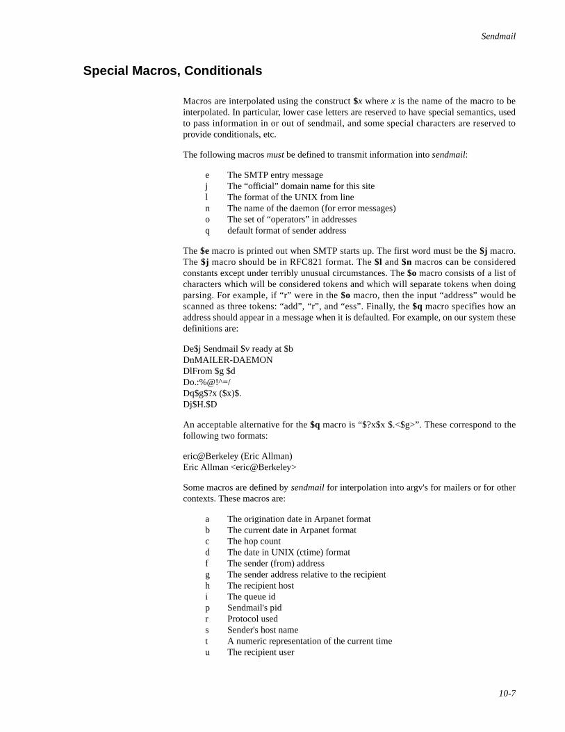
Sendmail
10-7
Special Macros, Conditionals 10
Macros are interpolated using the construct $x where x is the name of the macro to beinterpolated. In particular, lower case letters are reserved to have special semantics, usedto pass information in or out of sendmail, and some special characters are reserved toprovide conditionals, etc.
The following macros must be defined to transmit information into sendmail:
e The SMTP entry messagej The “official” domain name for this sitel The format of the UNIX from linen The name of the daemon (for error messages)o The set of “operators” in addressesq default format of sender address
The $e macro is printed out when SMTP starts up. The first word must be the $j macro.The $j macro should be in RFC821 format. The $l and $n macros can be consideredconstants except under terribly unusual circumstances. The $o macro consists of a list ofcharacters which will be considered tokens and which will separate tokens when doingparsing. For example, if “r” were in the $o macro, then the input “address” would bescanned as three tokens: “add”, “r”, and “ess”. Finally, the $q macro specifies how anaddress should appear in a message when it is defaulted. For example, on our system thesedefinitions are:
De$j Sendmail $v ready at $bDnMAILER-DAEMONDlFrom $g $dDo.:%@!^=/Dq$g$?x ($x)$.Dj$H.$D
An acceptable alternative for the $q macro is “$?x$x $.<$g>”. These correspond to thefollowing two formats:
eric@Berkeley (Eric Allman)Eric Allman <eric@Berkeley>
Some macros are defined by sendmail for interpolation into argv's for mailers or for othercontexts. These macros are:
a The origination date in Arpanet formatb The current date in Arpanet formatc The hop countd The date in UNIX (ctime) formatf The sender (from) addressg The sender address relative to the recipienth The recipient hosti The queue idp Sendmail's pidr Protocol useds Sender's host namet A numeric representation of the current timeu The recipient user
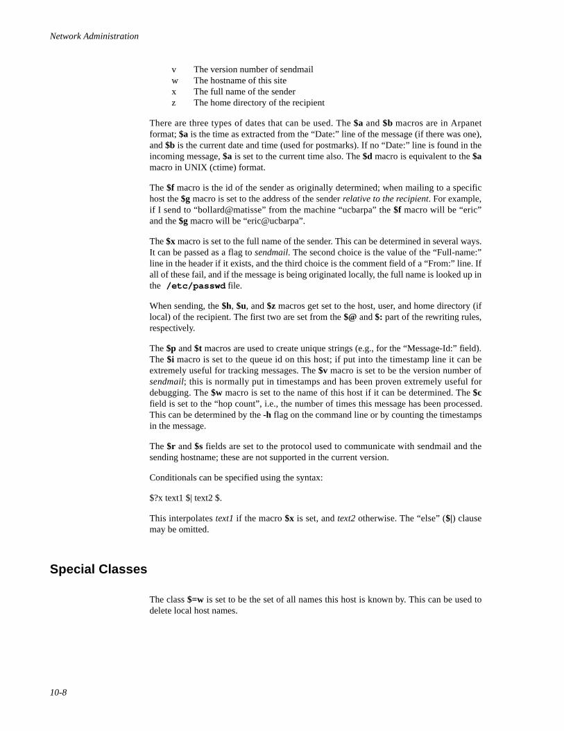
Network Administration
10-8
v The version number of sendmailw The hostname of this sitex The full name of the senderz The home directory of the recipient
There are three types of dates that can be used. The $a and $b macros are in Arpanetformat; $a is the time as extracted from the “Date:” line of the message (if there was one),and $b is the current date and time (used for postmarks). If no “Date:” line is found in theincoming message, $a is set to the current time also. The $d macro is equivalent to the $amacro in UNIX (ctime) format.
The $f macro is the id of the sender as originally determined; when mailing to a specifichost the $g macro is set to the address of the sender relative to the recipient. For example,if I send to “bollard@matisse” from the machine “ucbarpa” the $f macro will be “eric”and the $g macro will be “eric@ucbarpa”.
The $x macro is set to the full name of the sender. This can be determined in several ways.It can be passed as a flag to sendmail. The second choice is the value of the “Full-name:”line in the header if it exists, and the third choice is the comment field of a “From:” line. Ifall of these fail, and if the message is being originated locally, the full name is looked up inthe /etc/passwd file.
When sending, the $h, $u, and $z macros get set to the host, user, and home directory (iflocal) of the recipient. The first two are set from the $@ and $: part of the rewriting rules,respectively.
The $p and $t macros are used to create unique strings (e.g., for the “Message-Id:” field).The $i macro is set to the queue id on this host; if put into the timestamp line it can beextremely useful for tracking messages. The $v macro is set to be the version number ofsendmail; this is normally put in timestamps and has been proven extremely useful fordebugging. The $w macro is set to the name of this host if it can be determined. The $cfield is set to the “hop count”, i.e., the number of times this message has been processed.This can be determined by the -h flag on the command line or by counting the timestampsin the message.
The $r and $s fields are set to the protocol used to communicate with sendmail and thesending hostname; these are not supported in the current version.
Conditionals can be specified using the syntax:
$?x text1 $| text2 $.
This interpolates text1 if the macro $x is set, and text2 otherwise. The “else” ($|) clausemay be omitted.
Special Classes 10
The class $=w is set to be the set of all names this host is known by. This can be used todelete local host names.
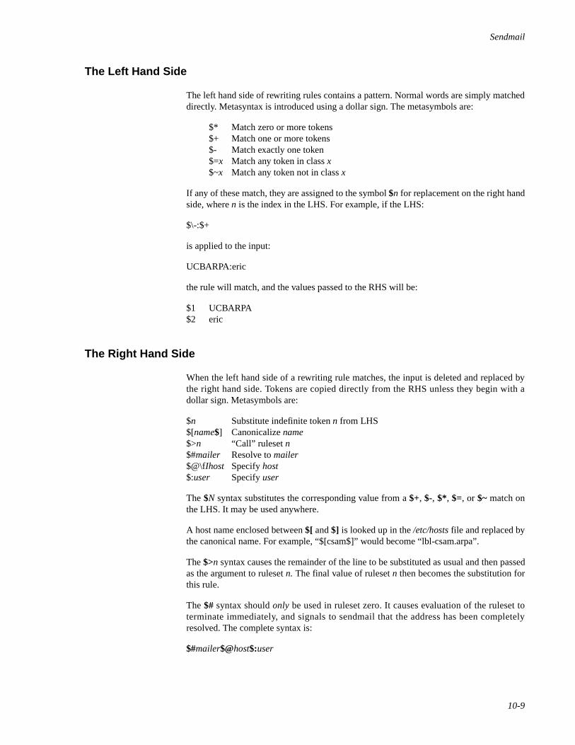
Sendmail
10-9
The Left Hand Side 10
The left hand side of rewriting rules contains a pattern. Normal words are simply matcheddirectly. Metasyntax is introduced using a dollar sign. The metasymbols are:
$* Match zero or more tokens$+ Match one or more tokens$- Match exactly one token$=x Match any token in class x$~x Match any token not in class x
If any of these match, they are assigned to the symbol $n for replacement on the right handside, where n is the index in the LHS. For example, if the LHS:
$\-:$+
is applied to the input:
UCBARPA:eric
the rule will match, and the values passed to the RHS will be:
$1 UCBARPA$2 eric
The Right Hand Side 10
When the left hand side of a rewriting rule matches, the input is deleted and replaced bythe right hand side. Tokens are copied directly from the RHS unless they begin with adollar sign. Metasymbols are:
$n Substitute indefinite token n from LHS$[name$] Canonicalize name$>n “Call” ruleset n$#mailer Resolve to mailer$@\fIhost Specify host$:user Specify user
The $N syntax substitutes the corresponding value from a $+, $-, $*, $=, or $~ match onthe LHS. It may be used anywhere.
A host name enclosed between $[ and $] is looked up in the /etc/hosts file and replaced bythe canonical name. For example, “$[csam$]” would become “lbl-csam.arpa”.
The $>n syntax causes the remainder of the line to be substituted as usual and then passedas the argument to ruleset n. The final value of ruleset n then becomes the substitution forthis rule.
The $# syntax should only be used in ruleset zero. It causes evaluation of the ruleset toterminate immediately, and signals to sendmail that the address has been completelyresolved. The complete syntax is:
$#mailer$@host$:user

Network Administration
10-10
This specifies the {mailer, host, user} 3-tuple necessary to direct the mailer. If the mailer islocal the host part may be omitted. The mailer and host must be a single word, but the usermay be multi-part.
A RHS may also be preceded by a $@ or a $: to control evaluation. A $@ prefix causesthe ruleset to return with the remainder of the RHS as the value. A $: prefix causes the ruleto terminate immediately, but the ruleset to continue; this can be used to avoid continuedapplication of a rule. The prefix is stripped before continuing.
The $@ and $: prefixes may precede a $> spec; for example:
R$+ $:$>7$1
matches anything, passes that to ruleset seven, and continues; the $: is necessary to avoidan infinite loop.
Substitution occurs in the order described, that is, parameters from the LHS aresubstituted, hostnames are canonicalized, “subroutines” are called, and finally $#, $@, and$: are processed.
Semantics Of Rewriting Rule Sets 10
There are five rewriting sets that have specific semantics. These are related as depicted byFigure 10-1.
Figure 10-1. Rewriting Set Semantics
Where:
D - sender domain addition,S - mailer-specific sender rewriting, and R - mailer-specific recipient rewriting.
ADDRESS 3 D
0
1
2
S
R
4 MESSAGE
RESOLVED ADDRESS
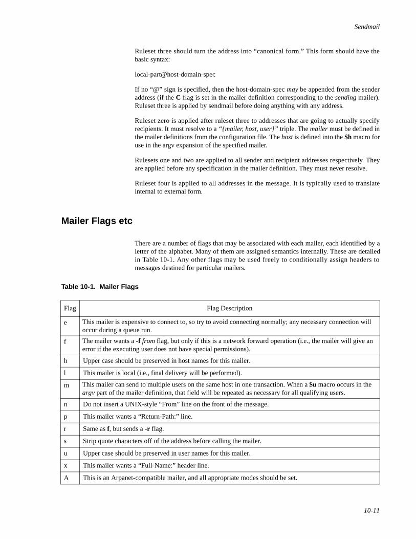
Sendmail
10-11
Ruleset three should turn the address into “canonical form.” This form should have thebasic syntax:
local-part@host-domain-spec
If no “@” sign is specified, then the host-domain-spec may be appended from the senderaddress (if the C flag is set in the mailer definition corresponding to the sending mailer).Ruleset three is applied by sendmail before doing anything with any address.
Ruleset zero is applied after ruleset three to addresses that are going to actually specifyrecipients. It must resolve to a “{mailer, host, user}” triple. The mailer must be defined inthe mailer definitions from the configuration file. The host is defined into the $h macro foruse in the argv expansion of the specified mailer.
Rulesets one and two are applied to all sender and recipient addresses respectively. Theyare applied before any specification in the mailer definition. They must never resolve.
Ruleset four is applied to all addresses in the message. It is typically used to translateinternal to external form.
Mailer Flags etc 10
There are a number of flags that may be associated with each mailer, each identified by aletter of the alphabet. Many of them are assigned semantics internally. These are detailedin Table 10-1. Any other flags may be used freely to conditionally assign headers tomessages destined for particular mailers.
Table 10-1. Mailer Flags
Flag Flag Description
e This mailer is expensive to connect to, so try to avoid connecting normally; any necessary connection will occur during a queue run.
f The mailer wants a -f from flag, but only if this is a network forward operation (i.e., the mailer will give an error if the executing user does not have special permissions).
h Upper case should be preserved in host names for this mailer.
l This mailer is local (i.e., final delivery will be performed).
m This mailer can send to multiple users on the same host in one transaction. When a $u macro occurs in the argv part of the mailer definition, that field will be repeated as necessary for all qualifying users.
n Do not insert a UNIX-style “From” line on the front of the message.
p This mailer wants a “Return-Path:” line.
r Same as f, but sends a -r flag.
s Strip quote characters off of the address before calling the mailer.
u Upper case should be preserved in user names for this mailer.
x This mailer wants a “Full-Name:” header line.
A This is an Arpanet-compatible mailer, and all appropriate modes should be set.
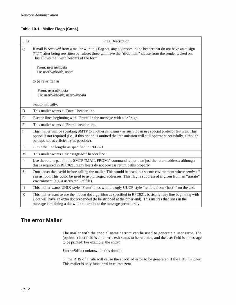
Network Administration
10-12
The error Mailer 10
The mailer with the special name “error” can be used to generate a user error. The(optional) host field is a numeric exit status to be returned, and the user field is a messageto be printed. For example, the entry:
$#error$:Host unknown in this domain
on the RHS of a rule will cause the specified error to be generated if the LHS matches.This mailer is only functional in ruleset zero.
C If mail is received from a mailer with this flag set, any addresses in the header that do not have an at sign (“@”) after being rewritten by ruleset three will have the “@domain” clause from the sender tacked on. This allows mail with headers of the form:
From: usera@hosta To: userb@hostb, userc
to be rewritten as:
From: usera@hosta To: userb@hostb, userc@hosta
%automatically.
D This mailer wants a “Date:” header line.
E Escape lines beginning with “From” in the message with a “>” sign.
F This mailer wants a “From:” header line.
I This mailer will be speaking SMTP to another sendmail - as such it can use special protocol features. This option is not required (i.e., if this option is omitted the transmission will still operate successfully, although perhaps not as efficiently as possible).
L Limit the line lengths as specified in RFC821.
M This mailer wants a “Message-Id:” header line.
P Use the return-path in the SMTP “MAIL FROM:” command rather than just the return address; although this is required in RFC821, many hosts do not process return paths properly.
S Don't reset the userid before calling the mailer. This would be used in a secure environment where sendmailran as root. This could be used to avoid forged addresses. This flag is suppressed if given from an “unsafe”environment (e.g, a user's mail.cf file).
U This mailer wants UNIX-style “From” lines with the ugly UUCP-style “remote from <host>” on the end.
X This mailer want to use the hidden dot algorithm as specified in RFC821; basically, any line beginning with a dot will have an extra dot prepended (to be stripped at the other end). This insures that lines in the message containing a dot will not terminate the message prematurely.
Table 10-1. Mailer Flags (Cont.)
Flag Flag Description
Sendmail
10-13
Building a Configuration File 10
Building a configuration table from scratch is an extremely difficult job. Fortunately, it isalmost never necessary to do so; nearly every situation that may come up may be resolvedby changing an existing table. In any case, it is critical that you understand what it is thatyou are trying to do and come up with a philosophy for the configuration table. Thissection is intended to explain what the real purpose of a configuration table is and to giveyou some ideas for what your philosophy might be.
Purpose 10
The configuration table has three major purposes. The first and simplest is to set up theenvironment for sendmail. This involves setting the options, defining a few criticalmacros, etc. Since these are described in other places, we will not go into more detail here.
The second purpose is to rewrite addresses in the message. This should typically be donein two phases. The first phase maps addresses in any format into a canonical form. Thisshould be done in ruleset three. The second phase maps this canonical form into the syntaxappropriate for the receiving mailer. Sendmail does this in three subphases. Rulesets oneand two are applied to all sender and recipient addresses respectively. After this, you mayspecify per-mailer rulesets for both sender and recipient addresses; this allows mailer-specific customization. Finally, ruleset four is applied to do any default conversion toexternal form.
The third purpose is to map addresses into the actual set of instructions necessary to getthe message delivered. Ruleset zero must resolve to the internal form, which is in turnused as a pointer to a mailer descriptor. The mailer descriptor describes the interfacerequirements of the mailer.
Philosophy 10
The particular philosophy you choose will depend heavily on the size and structure ofyour organization. A few possible philosophies are presented here.
One general point applies to all of these philosophies: it is almost always a mistake to tryto do full name resolution. For example, if you are trying to get names of the form“user@hos t ” to the Arpane t , i t does no t pay to rou te them to“xyzvax!decvax!ucbvax!c70:user@host” since you then depend on several links not underyour control . The best approach to th is problem is to s imply forward to“xyzvax!user@host” and let xyzvax worry about it from there. In summary, just get themessage closer to the destination, rather than determining the full path.
Large Site, Many Hosts - Minimum Information 10
Berkeley is an example of a large site, i.e., more than two or three hosts. They havedecided that the only reasonable philosophy in their environment is to designate one hostas the guru for their site. It must be able to resolve any piece of mail it receives. The other
Network Administration
10-14
sites should have the minimum amount of information they can get away with. In addition,any information they do have should be hints rather than solid information.
For example, a typical site on their local ethernet network is “monet”. Monet has a list ofknown ethernet hosts; if it receives mail for any of them, it can do direct delivery. If itreceives mail for any unknown host, it just passes it directly to “ucbvax”, their master host.Ucbvax may determine that the host name is illegal and reject the message, or may be ableto do delivery. However, it is important to note that when a new ethernet host is added, theonly host that must have its tables updated is ucbvax; the others may be updated as conve-nient, but this is not critical.
This picture is slightly muddied due to network connections that are not actually locatedon ucbvax. For example, their TCP connection is currently on “ucbarpa”. However, monet“does not” know about this; the information is hidden totally between ucbvax anducbarpa. Mail going from monet to a TCP host is transferred via the ethernet from monetto ucbvax, then via the ethernet from ucbvax to ucbarpa, and then is submitted to theArpanet. Although this involves some extra hops, they feel this is an acceptable trade-off.
An interesting point is that it would be possible to update monet to send TCP mail directlyto ucbarpa if the load got too high; if monet failed to note a host as a TCP host it would govia ucbvax as before, and if monet incorrectly sent a message to ucbarpa it would still besent by ucbarpa to ucbvax as before. The only problem that can occur is loops, as ifucbarpa thought that ucbvax had the TCP connection and vice versa. For this reason,updates should always happen to the master host first.
This philosophy results as much from the need to have a single source for theconfiguration files (typically built using m4(1) or some similar tool) as any logical need.Maintaining more than three separate tables by hand is essentially an impossible job.
Small Site - Complete Information 10
A small site (two or three hosts) may find it more reasonable to have complete informationat each host. This would require that each host know exactly where each networkconnection is, possibly including the names of each host on that network. As long as thesite remains small and the configuration remains relatively static, the update problem willprobably not be too great.
Single Host 10
This is in some sense the trivial case. The only major issue is trying to insure that youdon't have to know too much about your environment. For example, if you have a UUCPconnection you might find it useful to know about the names of hosts connected directly toyou, but this is really not necessary since this may be determined from the syntax.
Relevant Issues 10
The canonical form you use should almost certainly be as specified in the Arpanetprotocols RFC819 and RFC822.
Sendmail
10-15
RFC822 describes the format of the mail message itself. Sendmail follows this RFCclosely, to the extent that many of the standards described in this document can not bechanged without changing the code. In particular, the following characters have specialinterpretations:
< > ( ) “ \\
Any attempt to use these characters for other than their RFC822 purpose in addresses isprobably doomed to disaster.
RFC819 describes the specifics of the domain-based addressing. This is touched on inRFC822 as well. Essentially each host is given a name which is a right-to-left dot qualifiedpseudo-path from a distinguished root. The elements of the path need not be physicalhosts; the domain is logical rather than physical. For example, at Berkeley one legal host is“a.cc.berkeley.arpa”; reading from right to left, “arpa” is a top level domain (related to, butnot limited to, the physical Arpanet), “berkeley” is both an Arpanet host and a logicaldomain which is actually interpreted by a host called ucbvax (which is actually just the“major” host for this domain), “cc” represents the Computer Center, (in this case a strictlylogical entity), and “a” is a host in the Computer Center; this particular host happens to beconnected via berknet, but other hosts might be connected via Ethernet or some other net-work.
Beware when reading RFC819 that there are a number of errors in it.
How To Proceed 10
Once you have decided on a philosophy, it is worth examining the available configurationtables to decide if any of them are close enough to steal major parts of. Even under theworst of conditions, there is a fair amount of boiler plate that can be collected safely.
The next step is to build ruleset three. This will be the hardest part of the job. Beware ofdoing too much to the address in this ruleset, since anything you do will reflect through tothe message. In particular, stripping of local domains is best deferred, since this can leaveyou with addresses with no domain spec at all. Since sendmail likes to append the sendingdomain to addresses with no domain, this can change the semantics of addresses. Also tryto avoid fully qualifying domains in this ruleset. Although technically legal, this can leadto unpleasantly and unnecessarily long addresses reflected into messages. The Berkeleyconfiguration files define ruleset nine to qualify domain names and strip local domains.This is called from ruleset zero to get all addresses into a cleaner form.
Once you have ruleset three finished, the other rulesets should be relatively trivial. If youneed hints, examine the supplied configuration tables.
Testing The Rewriting Rules - The -bt Flag 10
When you build a configuration table, you can do a certain amount of testing using the“test mode” of sendmail. For example, you could invoke Sendmail as:
sendmail -bt -Ctest.cf
Network Administration
10-16
which would read the configuration file “test.cf” and enter test mode. In this mode, youenter lines of the form:
rwset address
where rwset is the rewriting set you want to use and address is an address to apply the setto. Test mode shows you the steps it takes as it proceeds, finally showing you the address itends up with. You may use a comma separated list of rwsets for sequential application ofrules to an input; ruleset three is always applied first. For example:
1,21,4 monet:bollard
first applies ruleset three to the input “monet:bollard”. Ruleset one is then applied to theoutput of ruleset three, followed similarly by rulesets twenty-one and four.
If you need more detail, you can also use the “-d21” flag to turn on more debugging. Forexample,
sendmail -bt -d21.99
turns on an incredible amount of information; a single word address is probably going toprint out several pages worth of information.
Building Mailer Descriptions 10
To add an outgoing mailer to your mail system, you will have to define the characteristicsof the mailer.
Each mailer must have an internal name. This can be arbitrary, except that the names“local” and “prog” must be defined.
The pathname of the mailer must be given in the P field. If this mailer should be accessedvia an IPC connection, use the string “[IPC]” instead.
The F field defines the mailer flags. You should specify an “f” or “r” flag to pass the nameof the sender as a -f or -r flag respectively. These flags are only passed if they were passedto sendmail, so that mailers that give errors under some circumstances can be placated. Ifthe mailer is not picky you can just specify “-f $g” in the argv template. If the mailer mustbe called as root the “S” flag should be given; this will not reset the userid before callingthe mailer. Sendmail must be running setuid to root for this to work. If this mailer is local(i.e., will perform final delivery rather than another network hop) the “l” flag should begiven. Quote characters (backslashes and “ marks) can be stripped from addresses if the“s” flag is specified; if this is not given they are passed through. If the mailer is capable ofsending to more than one user on the same host in a single transaction the “m” flag shouldbe stated. If this flag is on, then the argv template containing $u will be repeated for eachunique user on a given host. The “e” flag will mark the mailer as being “expensive”, whichwill cause sendmail to defer connection until a queue run. The “c” configuration optionmust be given for this to be effective.
An unusual case is the “C” flag. This flag applies to the mailer that the message is receivedfrom, rather than the mailer being sent to; if set, the domain spec of the sender (i.e., the“@host.domain” part) is saved and is appended to any addresses in the message that donot already contain a domain spec. For example, a message of the form:

Sendmail
10-17
From: eric@ucbarpaTo: wnj@monet, mckusick
will be modified to:
From: eric@ucbarpaTo: wnj@monet, mckusick@ucbarpa
if and only if the “C” flag is defined in the mailer corresponding to “eric@ucbarpa”.
Other flags are described in Table 10-1.
The S and R fields in the mailer description are per-mailer rewriting sets to be applied tosender and recipient addresses respectively. These are applied after the sending domain isappended and the general rewriting sets (numbers one and two) are applied, but before theoutput rewrite (ruleset four) is applied. A typical use is to append the current domain toaddresses that do not already have a domain. For example, a header of the form:
From: eric
might be changed to be:
From: eric@ucbarpa
or
From: ucbvax!eric
depending on the domain it is being shipped into. These sets can also be used to do specialpurpose output rewriting in cooperation with ruleset four.
The E field defines the string to use as an end-of-line indication. A string containing onlynewline is the default. The usual backslash escapes (\\r, \\n, \\f, \\b) may be used.
Finally, an argv template is given as the E field. It may have embedded spaces. If there isno argv with a $u macro in it, sendmail will speak SMTP to the mailer. If the pathname forthis mailer is “[IPC]”, the argv should be
IPC $h [port ]
where port is the optional port number to connect to.
For example, the specifications:
Mlocal,P=/bin/mail, F=rlsm S=10 R=20, A=mail -d $uMether,P=[IPC], F=meC, S=11, R=21, A=IPC $h, M=100000
specifies a mailer to do local delivery and a mailer for ethernet delivery. The first is called“local”, is located in the file “/bin/mail”, takes a picky -r flag, does local delivery, quotesshould be stripped from addresses, and multiple users can be delivered at once; ruleset tenshould be applied to sender addresses in the message and ruleset twenty should be appliedto recipient addresses; the argv to send to a message will be the word “mail”, the word“-d”, and words containing the name of the receiving user. If a -r flag is inserted it will bebetween the words “mail” and “-d”. The second mailer is called “ether”, it should beconnected to via an IPC connection, it can handle multiple users at once, connectionsshould be deferred, and any domain from the sender address should be appended to anyreceiver name without a domain; sender addresses should be processed by ruleset eleven

Network Administration
10-18
and recipient addresses by ruleset twenty-one. There is a 100,000 byte limit on messagespassed through this mailer.
Enabling Sendmail 10
Changes are required to the mailsurr(4) file (/etc/mail/mailsurr ) in order tohave sendmail(1M) process outgoing remote mail.
Note that sendmail(1M) typically uses mail(1) to deliver local mail. Hence, it is notadvisable to configure the mailsurr(4) fi le so that local mail is sent tosendmail(1M) . This would generally lead to sendmail(1M) recusively callingmail(1) and vice versa until eventually an error occurs.
There are several different ways that mailsurr(4) might be changed to enablesendmail(1M) . The following lists typical changes required - (these are alsodocumented in the mailsurr(4) file).
In Address Translation section (i.e. part 2) :
- Disable -ALL- address translation commands. (Note that it isexpected that similar translations will be done by sendmail(1M)as specified by the configuration file.
- Enable the translation command that invokes ucb mail alias. This isused to do sendmail(1M) alias processing on all mail - local andremote.
In Delivery Commands section (i.e. part 3) :
- Disable uux and smtpqer. Enable sendmail(1M) .
It is also possible to have sendmail(1M) process incoming remote mail instead ofsmptd(1M) (SMTP daemon).
- Disable smtpd(1M) by removing the entry for it in the inetdconfiguration file /etc/inet/inetd.conf .
- Enable sendmail daemon in file /etc/inet/rc.inet .
Sendmail Utilities 10
A brief description of sendmail(1M) utilities:
/usr/ucblib/sendmail - sendmail(1M)
/usr/ucb/mailq - displays contents of sendmail queue.
/usr/ucb/mailstats - displays sendmail statistics.
Sendmail
10-19
/usr/ucb/mconnect - connect to mail server on remote host.
/usr/ucb/newaliases - rebuilds sendmail alias database.
/usr/ucblib/ucbmailalias - translate sendmail alias name.
Sendmail Mail Queue 10
The mail queue should be processed transparently. However, you may find that manualintervention is sometimes necessary.
The command
/usr/ucblib/mqueue (or /usr/ucblib/sendmail -bp )
will produce a listing of the queued mail with: id numbers, message size, message date,time message was queued, sender and recipients.
The queue files are located in the directory /var/spool/mqueue . Files have the formxfAA99999 where AA99999 is the id of the file. x is the type and can be one of:
d - date file.l - lock file.n - id creation temporary file.q - queue control file.t - temporary file.x - transcript file.
qf files are structured as a series of lines beginning with a code letter. The code letters areas follows:
D - name of date file.H - header definition.M - message.P - message priority.R - recipient address.S - sender address.T - job creation time.
Sendmail Log 10
If your system is running syslog(1M) (enabled by default), then a log of sendmailoperations can be maintained. The location of the log can be specified in the file /etc/syslog.conf . By default, log data associated with sendmail is kept at /var/spool/mqueue/syslog .
Each line in the log consists of a timestamp, the name of the system that generated it, theword sendmail and a message.

Network Administration
10-20
The log can grow to be quite large. The amount of information that is logged can becontrolled by indicating a logging level. At the lowest level only extremely strange situa-tions are logged. At the highest level, even mundane and uninteresting events are logged.
The following table lists the definitions for the log levels. By default, the log levelspecified is 2 in the subsidiary configuration file (subsidiary.cf ) and 1 in the mainconfiguration file (main.cf ).
0 - no logging.1 - major problems only.2 - message collections and failed deliveries.3 - successful deliveries.4 - deferred messages.5 - normal queued messages.6 - unusual but benign incidents.9 - queue id to external message id mappings.12 - debugging messages.16 - verbose information about the mail queue.

-21
3Part 3TCP/IP Network Administration
Replace with Part 3 tab

Network Administration
-22
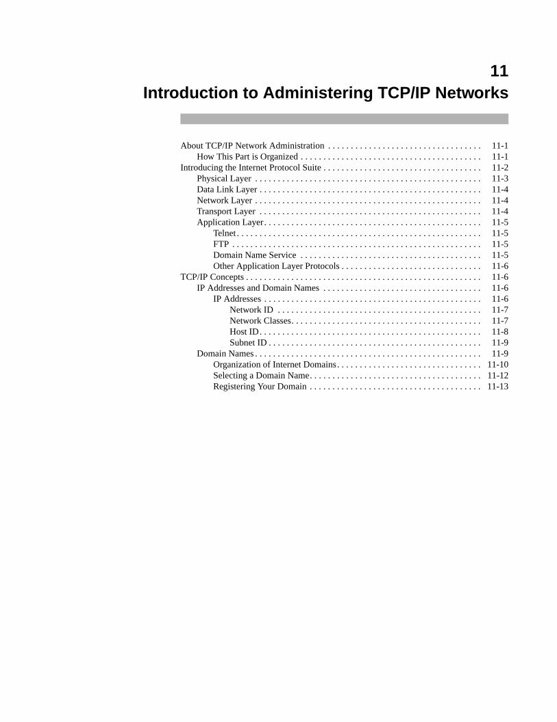
11Introduction to Administering TCP/IP Networks
About TCP/IP Network Administration . . . . . . . . . . . . . . . . . . . . . . . . . . . . . . . . . . 11-1How This Part is Organized . . . . . . . . . . . . . . . . . . . . . . . . . . . . . . . . . . . . . . . . 11-1
Introducing the Internet Protocol Suite . . . . . . . . . . . . . . . . . . . . . . . . . . . . . . . . . . . 11-2Physical Layer . . . . . . . . . . . . . . . . . . . . . . . . . . . . . . . . . . . . . . . . . . . . . . . . . . 11-3Data Link Layer . . . . . . . . . . . . . . . . . . . . . . . . . . . . . . . . . . . . . . . . . . . . . . . . . 11-4Network Layer . . . . . . . . . . . . . . . . . . . . . . . . . . . . . . . . . . . . . . . . . . . . . . . . . . 11-4Transport Layer . . . . . . . . . . . . . . . . . . . . . . . . . . . . . . . . . . . . . . . . . . . . . . . . . 11-4Application Layer. . . . . . . . . . . . . . . . . . . . . . . . . . . . . . . . . . . . . . . . . . . . . . . . 11-5
Telnet . . . . . . . . . . . . . . . . . . . . . . . . . . . . . . . . . . . . . . . . . . . . . . . . . . . . . . 11-5FTP . . . . . . . . . . . . . . . . . . . . . . . . . . . . . . . . . . . . . . . . . . . . . . . . . . . . . . . 11-5Domain Name Service . . . . . . . . . . . . . . . . . . . . . . . . . . . . . . . . . . . . . . . . 11-5Other Application Layer Protocols . . . . . . . . . . . . . . . . . . . . . . . . . . . . . . . 11-6
TCP/IP Concepts . . . . . . . . . . . . . . . . . . . . . . . . . . . . . . . . . . . . . . . . . . . . . . . . . . . . 11-6IP Addresses and Domain Names . . . . . . . . . . . . . . . . . . . . . . . . . . . . . . . . . . . 11-6
IP Addresses . . . . . . . . . . . . . . . . . . . . . . . . . . . . . . . . . . . . . . . . . . . . . . . . 11-6Network ID . . . . . . . . . . . . . . . . . . . . . . . . . . . . . . . . . . . . . . . . . . . . . 11-7Network Classes. . . . . . . . . . . . . . . . . . . . . . . . . . . . . . . . . . . . . . . . . . 11-7Host ID. . . . . . . . . . . . . . . . . . . . . . . . . . . . . . . . . . . . . . . . . . . . . . . . . 11-8Subnet ID . . . . . . . . . . . . . . . . . . . . . . . . . . . . . . . . . . . . . . . . . . . . . . . 11-9
Domain Names . . . . . . . . . . . . . . . . . . . . . . . . . . . . . . . . . . . . . . . . . . . . . . . . . . 11-9Organization of Internet Domains. . . . . . . . . . . . . . . . . . . . . . . . . . . . . . . . 11-10Selecting a Domain Name. . . . . . . . . . . . . . . . . . . . . . . . . . . . . . . . . . . . . . 11-12Registering Your Domain . . . . . . . . . . . . . . . . . . . . . . . . . . . . . . . . . . . . . . 11-13

Network Administration
11-1
11Chapter 11Introduction to Administering TCP/IP Networks
111111
About TCP/IP Network Administration 11
The TCP/IP administration chapters explain how to set up and administer a network builton the TCP/IP Internet protocol family. The administrative steps needed are simple andfew, once you understand the concepts underlying them. Therefore, this guideconcentrates on the concepts that will allow you to install the most appropriate network foryour particular needs.
How This Part is Organized 11
The TCP/IP administration chapters are organized as follows:
• “Introduction to Administering TCP/IP Networks” describes the conceptsyou need to understand to effectively do TCP/IP administration for yoursystems.
• “Setting Up TCP/IP” contains step-by-step procedures for many basic tasksyou need to do as a TCP/IP administrator.
• “Setting Up Routers and Subnetworks” describes how to expand andmanage growing systems.
• “Managing TCP/IP Nodes Using SNMP” tells how to use SNMP toperform network monitoring and management functions.
• “Using Domain Name Service with TCP/IP” describes concepts andprocedures relating to domain name service.
• “Troubleshooting and Tuning TCP/IP” describes how to diagnoseproblems and tune your system to improve TCP/IP performance.
• “Obtaining IP Addresses” describes how to obtain and complete IP addressregistration forms.
• “Obtaining Domain Names” describes how to obtain and complete domainname registration forms.
• “Network Time Synchronization” describes how to synchronize timeamong the machines on your network.
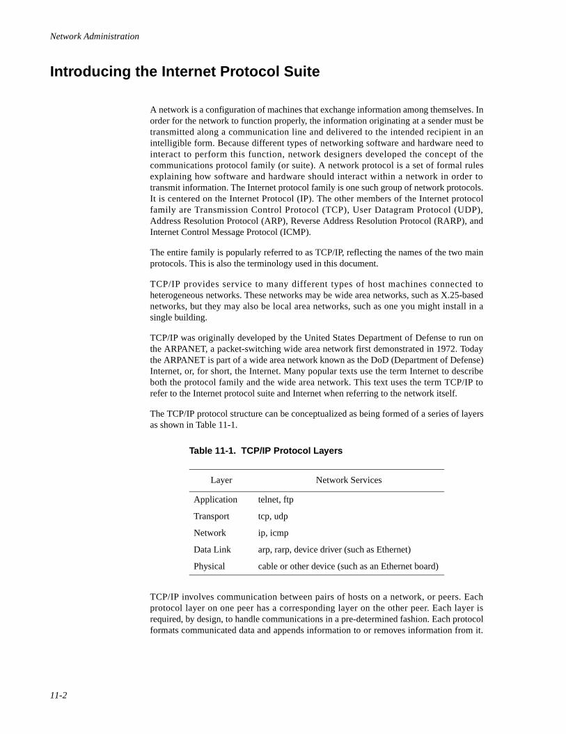
Network Administration
11-2
Introducing the Internet Protocol Suite 11
A network is a configuration of machines that exchange information among themselves. Inorder for the network to function properly, the information originating at a sender must betransmitted along a communication line and delivered to the intended recipient in anintelligible form. Because different types of networking software and hardware need tointeract to perform this function, network designers developed the concept of thecommunications protocol family (or suite). A network protocol is a set of formal rulesexplaining how software and hardware should interact within a network in order totransmit information. The Internet protocol family is one such group of network protocols.It is centered on the Internet Protocol (IP). The other members of the Internet protocolfamily are Transmission Control Protocol (TCP), User Datagram Protocol (UDP),Address Resolution Protocol (ARP), Reverse Address Resolution Protocol (RARP), andInternet Control Message Protocol (ICMP).
The entire family is popularly referred to as TCP/IP, reflecting the names of the two mainprotocols. This is also the terminology used in this document.
TCP/IP provides service to many different types of host machines connected toheterogeneous networks. These networks may be wide area networks, such as X.25-basednetworks, but they may also be local area networks, such as one you might install in asingle building.
TCP/IP was originally developed by the United States Department of Defense to run onthe ARPANET, a packet-switching wide area network first demonstrated in 1972. Todaythe ARPANET is part of a wide area network known as the DoD (Department of Defense)Internet, or, for short, the Internet. Many popular texts use the term Internet to describeboth the protocol family and the wide area network. This text uses the term TCP/IP torefer to the Internet protocol suite and Internet when referring to the network itself.
The TCP/IP protocol structure can be conceptualized as being formed of a series of layersas shown in Table 11-1.
TCP/IP involves communication between pairs of hosts on a network, or peers. Eachprotocol layer on one peer has a corresponding layer on the other peer. Each layer isrequired, by design, to handle communications in a pre-determined fashion. Each protocolformats communicated data and appends information to or removes information from it.
Table 11-1. TCP/IP Protocol Layers
Layer Network Services
Application telnet, ftp
Transport tcp, udp
Network ip, icmp
Data Link arp, rarp, device driver (such as Ethernet)
Physical cable or other device (such as an Ethernet board)
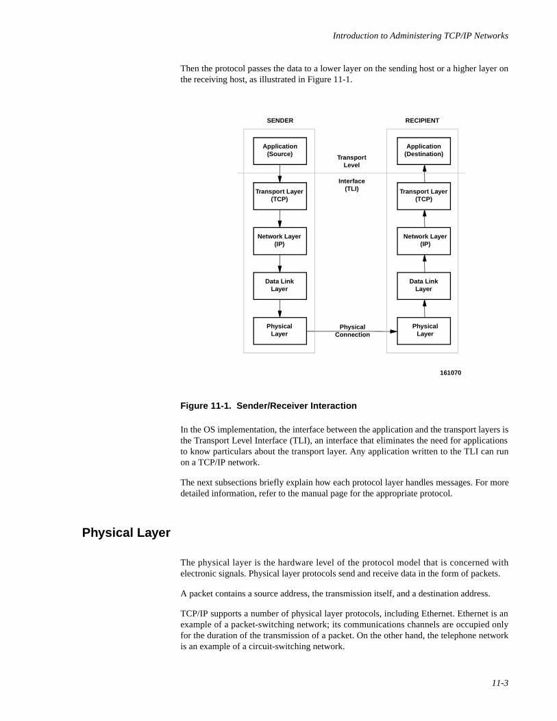
Introduction to Administering TCP/IP Networks
11-3
Then the protocol passes the data to a lower layer on the sending host or a higher layer onthe receiving host, as illustrated in Figure 11-1.
Figure 11-1. Sender/Receiver Interaction
In the OS implementation, the interface between the application and the transport layers isthe Transport Level Interface (TLI), an interface that eliminates the need for applicationsto know particulars about the transport layer. Any application written to the TLI can runon a TCP/IP network.
The next subsections briefly explain how each protocol layer handles messages. For moredetailed information, refer to the manual page for the appropriate protocol.
Physical Layer 11
The physical layer is the hardware level of the protocol model that is concerned withelectronic signals. Physical layer protocols send and receive data in the form of packets.
A packet contains a source address, the transmission itself, and a destination address.
TCP/IP supports a number of physical layer protocols, including Ethernet. Ethernet is anexample of a packet-switching network; its communications channels are occupied onlyfor the duration of the transmission of a packet. On the other hand, the telephone networkis an example of a circuit-switching network.
161070
Application(Source)
Application(Destination)
Transport Layer(TCP)
Transport Layer(TCP)
Data LinkLayer
PhysicalConnection
TransportLevel
Interface(TLI)
Data LinkLayer
PhysicalLayer
PhysicalLayer
Network Layer(IP)
Network Layer(IP)
SENDER RECIPIENT
Network Administration
11-4
Data Link Layer 11
The data link layer is concerned with addressing at the physical, machine level. Protocolsat this layer are involved with communications controllers, their chips, and their buffers.Ethernet is supported at this layer by TCP/IP.
Two additional TCP/IP protocols, ARP and RARP, can be viewed as existing between thenetwork and data link layers. ARP is the Ethernet address resolution protocol. It mapsknown IP addresses (32 bits long) to Ethernet addresses (48 bits long).
RARP (or Reverse ARP) is the IP address resolution protocol. It maps known Ethernetaddresses (48 bits long) to IP addresses (32 bits long), the reverse of ARP.
Network Layer 11
IP (Internet Protocol) and Internet Control Message Protocol (ICMP) are the protocolspresent at the network layer.
IP provides machine-to-machine communication. It performs transmission routing bydetermining the path a transmission must take, based on the receiving machine's IPaddress. IP also provides transmission formatting services; it assembles data for transmis-sion into an internet datagram.
The datagram defines the structure and form in which the information is sent. If the data-gram is outgoing (received from the higher layer protocols), IP attaches an IP header to it.This header contains a number of parameters, including the IP addresses of the sendingand receiving hosts. For more information about IP, refer to the IP(7) manual page.
ICMP sends error or control messages to other hosts. For more information about ICMP,refer to the ICMP(7) manual page.
Transport Layer 11
The TCP/IP transport layer protocols enable communications between processes runningon separate machines. Protocols at this level are TCP and UDP.
TCP (Transmission Control Protocol) enables applications to talk to one another viavirtual circuits, as if connected by physical circuits. TCP is a connection-oriented, reliabledelivery protocol; any data written to a TCP connection will be received by its peer insequence, or an error indication will be returned.
UDP (User Datagram Protocol) is the alternative protocol available at the transport layer.UDP is a connectionless datagram protocol. Datagrams are groups of information trans-mitted as a unit to and from the upper layer protocols on sending and receiving hosts. UDPdatagrams use port numbers to specify sending and receiving processes. However, noattempt is made to recover from failure or loss; packets may be lost with no errorindication returned.
Whether TCP or UDP is used depends on the network application invoked by the user. Forexample, if the user invokes telnet , that application passes the user's request to TCP. If
Introduction to Administering TCP/IP Networks
11-5
the user's request involves the Domain Name Service, that application passes the requestto UDP.
For information about the TCP and UDP protocols, refer to the TCP(7) and UDP(7)manual pages.
Application Layer 11
A variety of TCP/IP protocols exist at the application layer. Here is a description of someof the more widely used.
Telnet 11
The Telnet protocol enables terminals and terminal-oriented processes to communicate ona network running TCP/IP. It is implemented as the program telnet on the localmachine and the daemon telnetd on the remote machine. telnet provides a userinterface through which two hosts can open communications with each other, then sendinformation on a character-by-character or line-by-line basis. The application includes aseries of commands, which are documented in the telnet(1) manual page. Thetelnetd daemon on the remote host handles requests from the telnet command. Formore information about telnetd, see the telnetd(1M) manual page.
FTP 11
The File Transfer Protocol (FTP) transfers files to and from a remote network. Theprotocol includes the ftp command on the local machine and the ftpd daemon on theremote machine. ftp lets you specify on the command line the host with whom you wantto initiate file transfer and options for transferring the file. The ftpd daemon on theremote host handles the requests from your ftp command.
The options to ftp , as well as the commands you invoke through the ftp commandinterpreter, are described on the ftp(1) manual page.
The services provided by the ftpd daemon are described on the ftpd(1M) manualpage.
Domain Name Service 11
The Domain Name Service (DNS) is a protocol that provides domain-name-to-address-mapping of hosts and mail recipients on a network. DNS is described on the named(1M)manual page.
For information on how to implement the Domain Name Service on your network, see thechapter “Using Domain Name Service with TCP/IP”.
Network Administration
11-6
Other Application Layer Protocols 11
Other application layer protocols exist that are also implemented as a program on the localmachine and a daemon on the remote machine. Examples of these are rlogin andrlogind , which permit a user to log on to a remote machine; rsh and rshd , whichenable the user to spawn a shell on a remote machine; and finger and fingerd , whichpermit a user to obtain information about users on remote machines.
To avoid having an excess of daemons running at all times, the daemon inetd is initiatedat start-up time. After consulting the /etc/inetd.conf file, inetd runs theappropriate daemons as needed. For example, the daemon rlogind will be run byinetd whenever there is a request for a remote login from another machine, and only atthat time and for the duration of the remote login.
TCP/IP Concepts 11
As you use the procedures and descriptions in this guide, there are concepts that come upagain and again. The following are descriptions of the most important concepts you shouldunderstand throughout this guide.
IP Addresses and Domain Names 11
In order for all computers connected to the Internet to be able to communicate with eachother, the Network Information Center (NIC) controls addresses and names in a way thatthey are unique across the entire Internet. If your organization wants to connect to theInternet, you apply to the NIC for an Internet network ID and a domain name. You thenassign host numbers and system names, respectively, within the assigned network ID anddomain.
IP Addresses 11
A TCP/IP network routes a packet according to the destination IP address, an addressprovided by the IP protocol on the sending host. IP addresses are 32-bit numbers thatuniquely identify every host computer connected to the Internet. This 32-bit address istypically represented as four numbers that are separated by dots. For example, thefollowing is an IP address:
137.65.208.51
Because each of the four numbers is represented by an eight-bit field (or octet), eachnumber must fall between 0 and 255. (The last field, however, can only be assignednumbers from 1-254 for a Class C address, or for a Class B address with an 8-bit subnet.This is because the host ID part of the address cannot be all 0's or all 1's.)
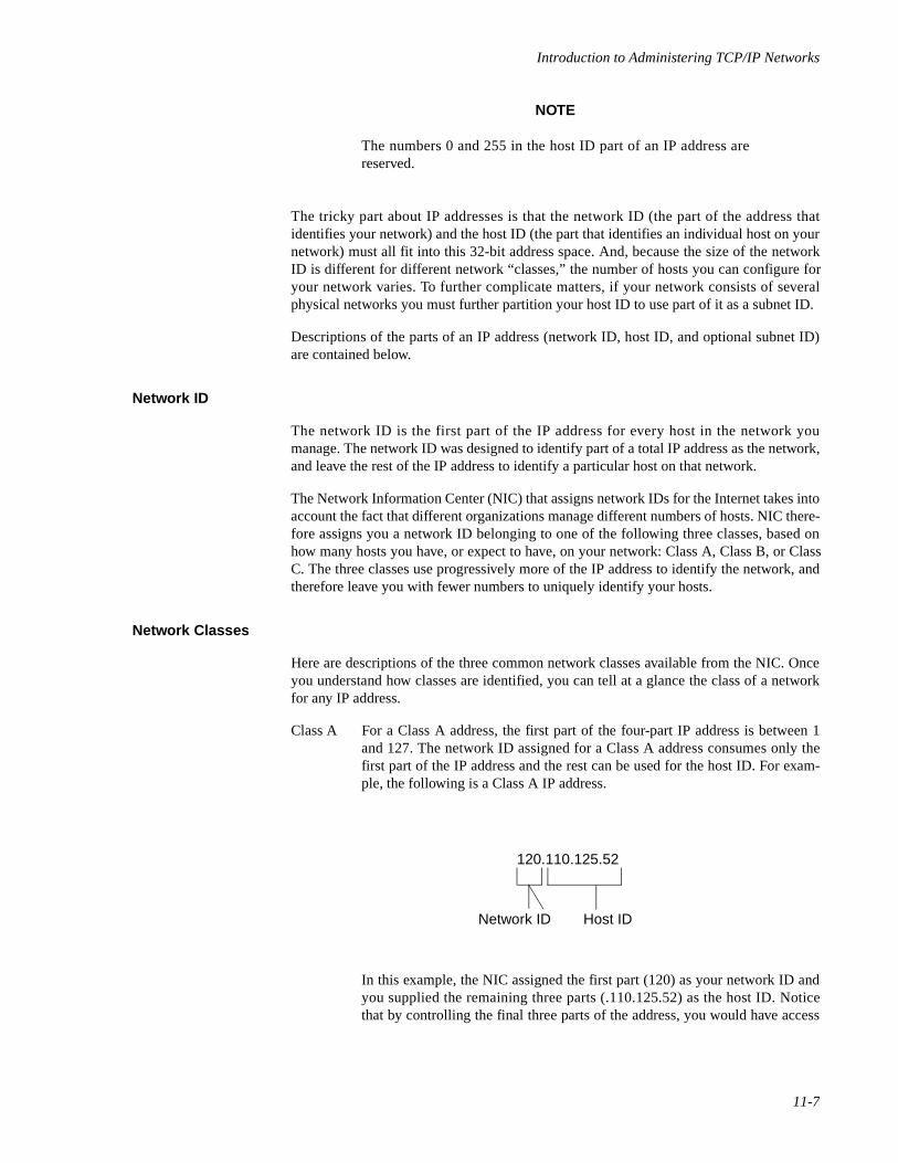
Introduction to Administering TCP/IP Networks
11-7
NOTE
The numbers 0 and 255 in the host ID part of an IP address arereserved.
The tricky part about IP addresses is that the network ID (the part of the address thatidentifies your network) and the host ID (the part that identifies an individual host on yournetwork) must all fit into this 32-bit address space. And, because the size of the networkID is different for different network “classes,” the number of hosts you can configure foryour network varies. To further complicate matters, if your network consists of severalphysical networks you must further partition your host ID to use part of it as a subnet ID.
Descriptions of the parts of an IP address (network ID, host ID, and optional subnet ID)are contained below.
Network ID 11
The network ID is the first part of the IP address for every host in the network youmanage. The network ID was designed to identify part of a total IP address as the network,and leave the rest of the IP address to identify a particular host on that network.
The Network Information Center (NIC) that assigns network IDs for the Internet takes intoaccount the fact that different organizations manage different numbers of hosts. NIC there-fore assigns you a network ID belonging to one of the following three classes, based onhow many hosts you have, or expect to have, on your network: Class A, Class B, or ClassC. The three classes use progressively more of the IP address to identify the network, andtherefore leave you with fewer numbers to uniquely identify your hosts.
Network Classes 11
Here are descriptions of the three common network classes available from the NIC. Onceyou understand how classes are identified, you can tell at a glance the class of a networkfor any IP address.
Class A For a Class A address, the first part of the four-part IP address is between 1and 127. The network ID assigned for a Class A address consumes only thefirst part of the IP address and the rest can be used for the host ID. For exam-ple, the following is a Class A IP address.
In this example, the NIC assigned the first part (120) as your network ID andyou supplied the remaining three parts (.110.125.52) as the host ID. Noticethat by controlling the final three parts of the address, you would have access
120.110.125.52
Network ID Host ID
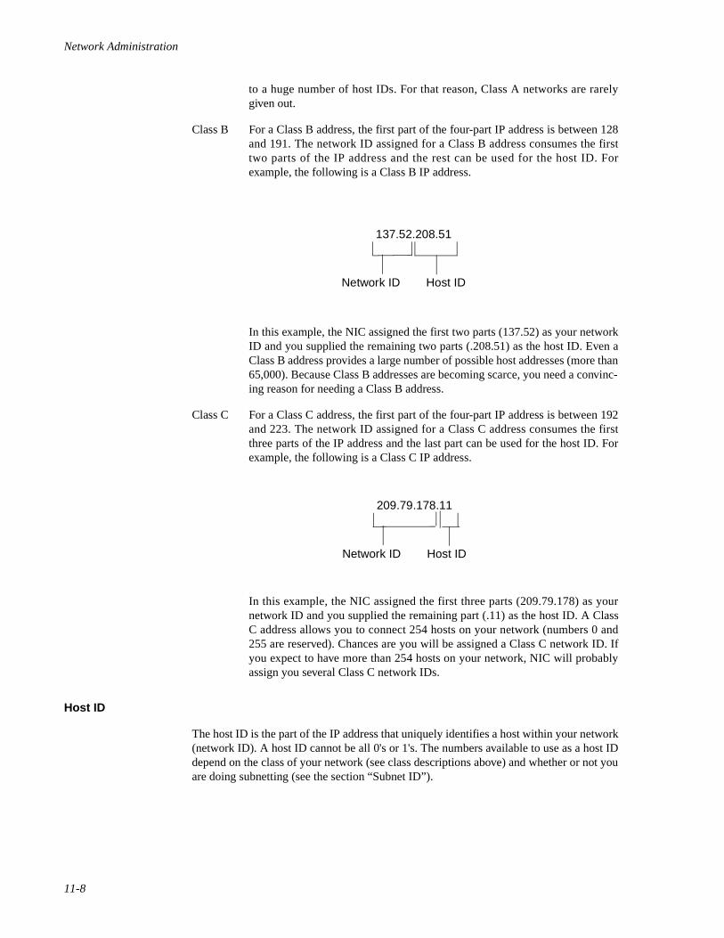
Network Administration
11-8
to a huge number of host IDs. For that reason, Class A networks are rarelygiven out.
Class B For a Class B address, the first part of the four-part IP address is between 128and 191. The network ID assigned for a Class B address consumes the firsttwo parts of the IP address and the rest can be used for the host ID. Forexample, the following is a Class B IP address.
In this example, the NIC assigned the first two parts (137.52) as your networkID and you supplied the remaining two parts (.208.51) as the host ID. Even aClass B address provides a large number of possible host addresses (more than65,000). Because Class B addresses are becoming scarce, you need a convinc-ing reason for needing a Class B address.
Class C For a Class C address, the first part of the four-part IP address is between 192and 223. The network ID assigned for a Class C address consumes the firstthree parts of the IP address and the last part can be used for the host ID. Forexample, the following is a Class C IP address.
In this example, the NIC assigned the first three parts (209.79.178) as yournetwork ID and you supplied the remaining part (.11) as the host ID. A ClassC address allows you to connect 254 hosts on your network (numbers 0 and255 are reserved). Chances are you will be assigned a Class C network ID. Ifyou expect to have more than 254 hosts on your network, NIC will probablyassign you several Class C network IDs.
Host ID 11
The host ID is the part of the IP address that uniquely identifies a host within your network(network ID). A host ID cannot be all 0's or 1's. The numbers available to use as a host IDdepend on the class of your network (see class descriptions above) and whether or not youare doing subnetting (see the section “Subnet ID”).
137.52.208.51
Network ID Host ID
209.79.178.11
Network ID Host ID
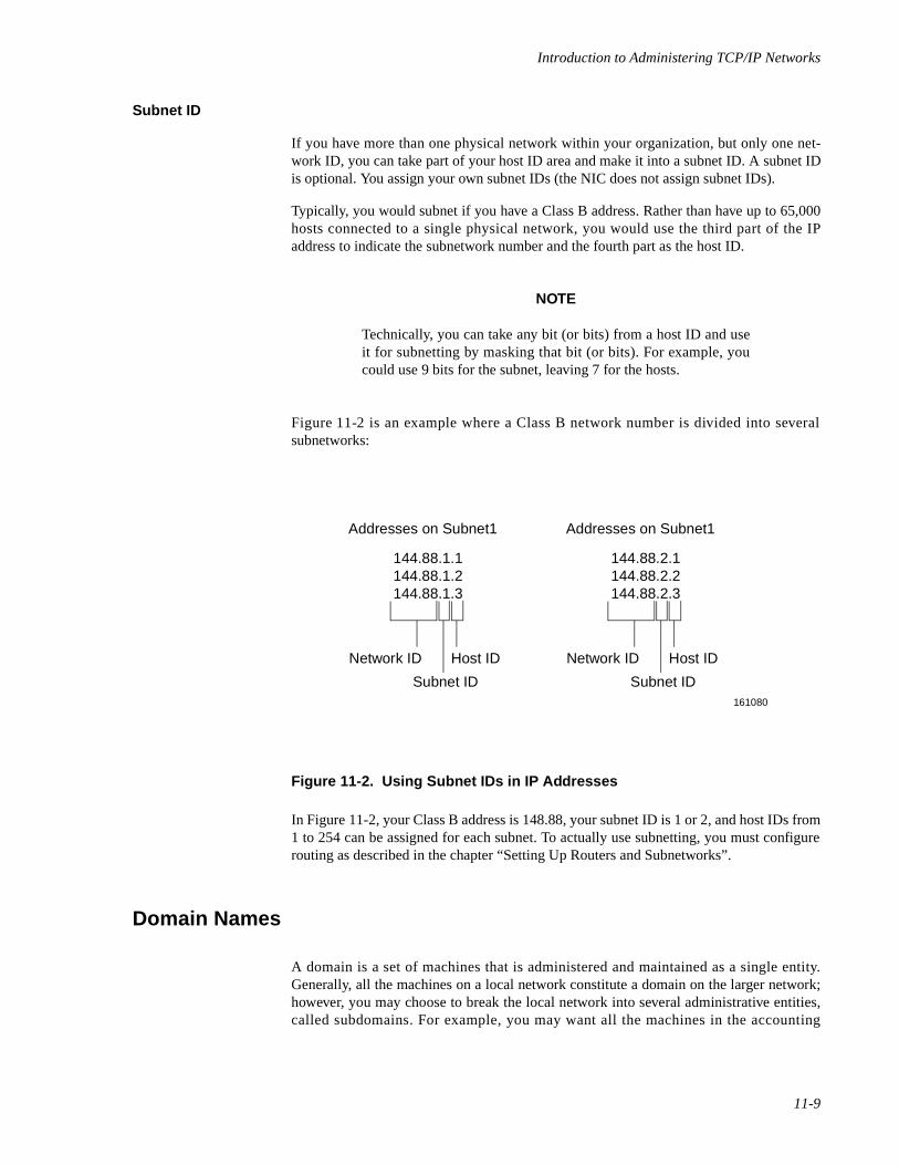
Introduction to Administering TCP/IP Networks
11-9
Subnet ID 11
If you have more than one physical network within your organization, but only one net-work ID, you can take part of your host ID area and make it into a subnet ID. A subnet IDis optional. You assign your own subnet IDs (the NIC does not assign subnet IDs).
Typically, you would subnet if you have a Class B address. Rather than have up to 65,000hosts connected to a single physical network, you would use the third part of the IPaddress to indicate the subnetwork number and the fourth part as the host ID.
NOTE
Technically, you can take any bit (or bits) from a host ID and useit for subnetting by masking that bit (or bits). For example, youcould use 9 bits for the subnet, leaving 7 for the hosts.
Figure 11-2 is an example where a Class B network number is divided into severalsubnetworks:
Figure 11-2. Using Subnet IDs in IP Addresses
In Figure 11-2, your Class B address is 148.88, your subnet ID is 1 or 2, and host IDs from1 to 254 can be assigned for each subnet. To actually use subnetting, you must configurerouting as described in the chapter “Setting Up Routers and Subnetworks”.
Domain Names 11
A domain is a set of machines that is administered and maintained as a single entity.Generally, all the machines on a local network constitute a domain on the larger network;however, you may choose to break the local network into several administrative entities,called subdomains. For example, you may want all the machines in the accounting
161080
Addresses on Subnet1
Network ID Host ID
Subnet ID
144.88.1.1144.88.1.2144.88.1.3
Addresses on Subnet1
Network ID Host ID
Subnet ID
144.88.2.1144.88.2.2144.88.2.3
Network Administration
11-10
department to comprise one subdomain, and all the machines in marketing to compriseanother.
To join the Internet, your domain must be named according to Internet namingconventions, and you must register your domain name with the NIC. Even if you do notintend to join the Internet at this time, it is recommended that you follow the Internetnaming conventions and register with the NIC to avoid problems in the future, should youdecide to join the network.
This section explains the Internet naming conventions. See the chapter “ObtainingDomain Names” for further information on getting domain name assignments from theNIC. (If you intend to join a public network other than the Internet, such as BITNET orCSNET, contact the organization that administers the network for information aboutnaming conventions and for a registration form.)
Organization of Internet Domains 11
The Internet consists of four levels of domain: the root level, the top level, the secondlevel, and the local level. Each level branches from the level above it. Below the local levelare hosts and, optionally, subdomains.
Figure 11-3 shows the different domain levels of the Internet and how they relate to eachother.
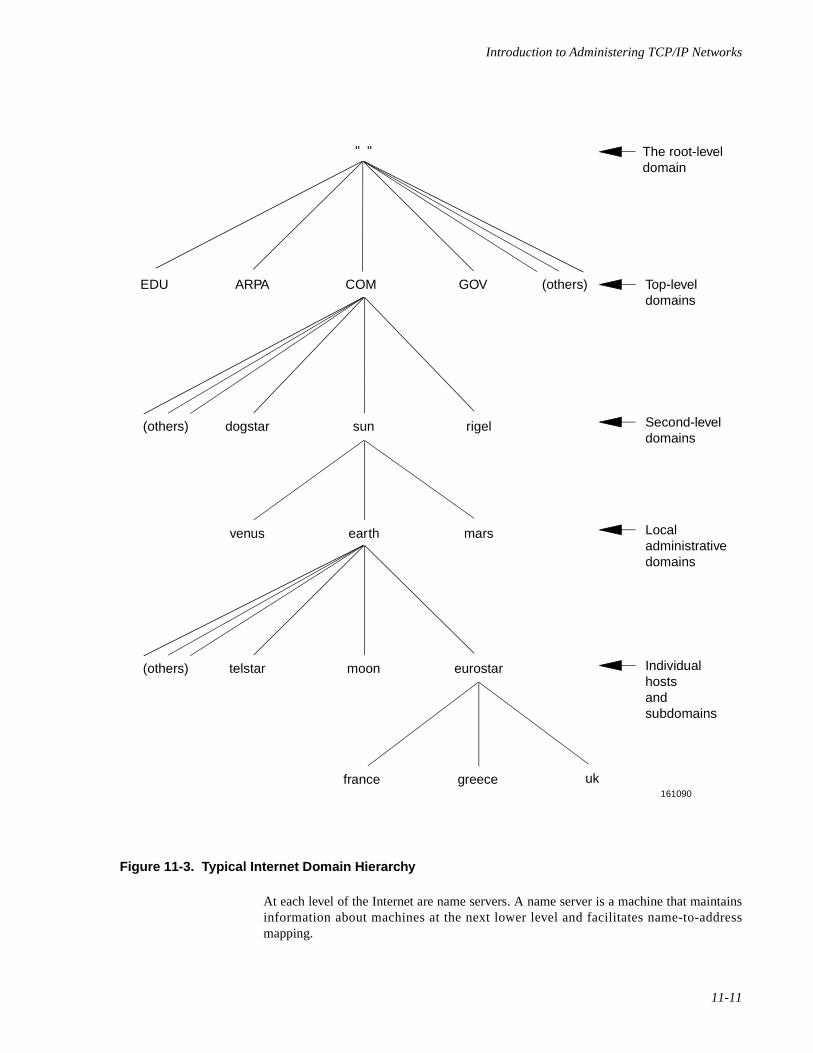
Introduction to Administering TCP/IP Networks
11-11
Figure 11-3. Typical Internet Domain Hierarchy
At each level of the Internet are name servers. A name server is a machine that maintainsinformation about machines at the next lower level and facilitates name-to-addressmapping.
" "
EDU ARPA COM GOV (others)
(others) rigelsundogstar
(others) eurostar
uk161090
moontelstar
greecefrance
marsearthvenus
Second-leveldomains
Localadministrativedomains
Individualhostsandsubdomains
Top-leveldomains
The root-leveldomain
Network Administration
11-12
The different levels of the Internet are described below:
Root-level domainThe root level is the top of the entire Internet; it is maintained by the NIC.(Organizations in charge of other public networks, such as BITNET andCSNET, also administer the roots of their networks.)
At the root level, the NIC administers root domain name servers, whichmaintain information about name servers at the next lower level.
Top-level domainsThe root level branches into top level domains. Currently, some Internet toplevel domains are EDU, ARPA, COM, GOV, MIL, NET, ORG, and US.
The names of the top level domains are assigned by the NIC. They reflect thetypes of networks that make up the domain. For example, EDU (anabbreviation of Educational) is a top level domain that consists of networksadministered by universities. COM (an abbreviation of Commercial) consistsof networks belonging to business organizations.
When you register with the NIC, it assigns your network to one of thesedomains, depending on your organization's function.
Second-level domainsEach top level domain branches into second level domains. Memberorganizations at the second level assign “domain administrators” to managetheir name servers, and the NIC assigns a “technical contact” to coordinateadministration across domains. Depending upon your site's size and require-ments, you may have domain administrator responsibilities.
Local administrative domainsWithin each second-level domain are local administrative domains. These arethe domains you administer for your organization. A local domain can be assmall as one host, or large enough to include many hosts and additional nameservers. It may also have other administrative domains (called subdomains)nested within it.
For more information about name servers and administrative responsibilities, seeChapter 15, "Using Domain Name Service with TCP/IP".
Selecting a Domain Name 11
The Internet is organized as a hierarchy of domains. The name space is organized as a treeaccording to organizational or administrative boundaries. Each node of the tree is adomain, which is given a label. The name of the domain is the concatenation of all thelabels of the domain from the root to the current domain, listed from right to left andseparated by dots. A host address for a host named monet at Podunk University might looklike this:
monet.podunk.EDU
The top level domain for educational institutions is EDU, podunk is a subdomain of EDUand monet is the name of the host.
Introduction to Administering TCP/IP Networks
11-13
When you name your domain, you must select a label that is unique within its domain. Forexample, you could use podunk as a label for a domain consisting of all machines atPodunk University, provided that another university in the domain EDU has not used thisname first. The label you assign a host within your domain must be unique as well, butonly within domain podunk .
Once you choose a label, you must concatenate it with the labels of all the higher leveldomains to create your domain name.
Domains are not limited to any fixed number of levels. For example, the AmalgamatedWidgit Company might be registered with the NIC as belonging to the domainWidgit.COM ; it might also have a subdomain called eng.Japan.Widgit.COM forthe engineering group within their Japan subsidiary, and another subdomain calledmktg.Japan.Widgit.COM for marketing in Japan. However, machines at companyheadquarters might belong to the subdomain called HQ.Widgit.COM .
NOTE
Upper- and lowercase letters are not significant in domain names.The traditional UNIX system convention is to use all lowercase;many other systems use uppercase.
At many sites, users name their individual hosts while the administrators name the servers.The administrator should ensure that there are no duplicate names within a domain byusing the nslookup program [see the nslookup(1M) manual page]. nslookup is aninteractive program that you can use (among other things) either to produce a listing of allthe hosts in the domain (by using the ls command at the > prompt), or to obtain informa-tion about a host. At the prompt, you enter the host's name. If the host is in the database,nslookup produces its address; otherwise, it informs you that the host does not exist.
Registering Your Domain 11
After choosing the name of your upper domain (the equivalent of Widgit.COM in theexample in the preceding section), you need to register it with a higher-level domain. Todo this, you should get in touch with the administrator of the higher domain. The top leveldomains are administered by the NIC at SRI International. To register a domain with NIC,you request the Domain Registration Form from the NIC and complete it according to theinstructions. See the chapter “Obtaining Domain Names” for information on getting andcompleting NIC domain registration forms. Once your domain is registered, you candivide it into subdomains as the need arises.

Network Administration
11-14
12Setting Up TCP/IP
Introduction to TCP/IP Setup . . . . . . . . . . . . . . . . . . . . . . . . . . . . . . . . . . . . . . . . . . 12-1Planning Your TCP/IP Network . . . . . . . . . . . . . . . . . . . . . . . . . . . . . . . . . . . . . . . . 12-1
Choosing Networking Media . . . . . . . . . . . . . . . . . . . . . . . . . . . . . . . . . . . . . . . 12-1Getting an IP Network Number and Domain Name . . . . . . . . . . . . . . . . . . . . . 12-1
IP addresses . . . . . . . . . . . . . . . . . . . . . . . . . . . . . . . . . . . . . . . . . . . . . . . . . 12-2Domain Names and System Names . . . . . . . . . . . . . . . . . . . . . . . . . . . . . . 12-2
Installing TCP/IP . . . . . . . . . . . . . . . . . . . . . . . . . . . . . . . . . . . . . . . . . . . . . . . . . . . . 12-3Creating a Simple TCP/IP Network . . . . . . . . . . . . . . . . . . . . . . . . . . . . . . . . . . . . . 12-3Expanding Your TCP/IP Network . . . . . . . . . . . . . . . . . . . . . . . . . . . . . . . . . . . . . . . 12-5
Setting Up Serial Connections . . . . . . . . . . . . . . . . . . . . . . . . . . . . . . . . . . . . . . 12-5Configuring Point-to-Point Protocol Connections (PPP) . . . . . . . . . . . . . . 12-5
Configuring SystemA (incoming ppp connection) . . . . . . . . . . . . . . . 12-6Configuring SystemB (outgoing ppp connection) . . . . . . . . . . . . . . . . 12-16
Configuring Serial Line IP Connections (SLIP) . . . . . . . . . . . . . . . . . . . . . 12-20Enabling SLIP Connections . . . . . . . . . . . . . . . . . . . . . . . . . . . . . . . . . 12-20Disabling SLIP Connections . . . . . . . . . . . . . . . . . . . . . . . . . . . . . . . . 12-20
Setting Up Routing. . . . . . . . . . . . . . . . . . . . . . . . . . . . . . . . . . . . . . . . . . . . . . . 12-21Setting Up Domain Name Service . . . . . . . . . . . . . . . . . . . . . . . . . . . . . . . . . . . 12-22Setting Up Subnetworks . . . . . . . . . . . . . . . . . . . . . . . . . . . . . . . . . . . . . . . . . . . 12-22Changing Available Services . . . . . . . . . . . . . . . . . . . . . . . . . . . . . . . . . . . . . . . 12-23Managing Remote Systems . . . . . . . . . . . . . . . . . . . . . . . . . . . . . . . . . . . . . . . . 12-24Synchronizing Time . . . . . . . . . . . . . . . . . . . . . . . . . . . . . . . . . . . . . . . . . . . . . . 12-24Maintaining Security . . . . . . . . . . . . . . . . . . . . . . . . . . . . . . . . . . . . . . . . . . . . . 12-24
Administering the hosts.equiv and .rhosts Files . . . . . . . . . . . . . . . . . . . . . 12-24The /etc/hosts.equiv File . . . . . . . . . . . . . . . . . . . . . . . . . . . . . . . . . . . . . . . 12-25
Example . . . . . . . . . . . . . . . . . . . . . . . . . . . . . . . . . . . . . . . . . . . . . . . . 12-26The .rhosts File. . . . . . . . . . . . . . . . . . . . . . . . . . . . . . . . . . . . . . . . . . . 12-26Example 1 . . . . . . . . . . . . . . . . . . . . . . . . . . . . . . . . . . . . . . . . . . . . . . 12-27Example 2 . . . . . . . . . . . . . . . . . . . . . . . . . . . . . . . . . . . . . . . . . . . . . . 12-27
Security Issues. . . . . . . . . . . . . . . . . . . . . . . . . . . . . . . . . . . . . . . . . . . . . . . 12-28Disabling the TCP/IP Network Services. . . . . . . . . . . . . . . . . . . . . . . . . . . 12-28
TCP/IP Services and Enhanced Security Issues. . . . . . . . . . . . . . . . . . . . . . . . . 12-29Minimizing TCP/IP Security Risks. . . . . . . . . . . . . . . . . . . . . . . . . . . . . . . 12-29TCP/IP and Secure Device Handling . . . . . . . . . . . . . . . . . . . . . . . . . . . . . 12-29SYS_PRIVATE and USER_LOGIN Security Levels . . . . . . . . . . . . . . . . . 12-30
Setting Up the Network Administrator's Login . . . . . . . . . . . . . . . . . . 12-30SYS_PRIVATE Level Executables . . . . . . . . . . . . . . . . . . . . . . . . . . . 12-30USER_LOGIN Level Executables. . . . . . . . . . . . . . . . . . . . . . . . . . . . 12-31SYS_PUBLIC-level Files . . . . . . . . . . . . . . . . . . . . . . . . . . . . . . . . . . 12-31

Network Administration
12-1
12Chapter 12Setting Up TCP/IP
121212
Introduction to TCP/IP Setup 12
This chapter contains procedures you need to configure and run TCP/IP on your computer.The chapter includes information about controlling access to your computer by remoteusers. It also contains a section explaining security issues related to the use of Internet net-work services with the Enhanced Security package.
Follow the step-by-step examples in this chapter. If there is something you don't knowhow to do, refer to the other chapters in this guide for more details on the facility.
Planning Your TCP/IP Network 12
Whether you are connecting a few computers in a single building or accessing thousandsof computers world wide, some planning is needed to configure your TCP/IP network.Before you install and configure TCP/IP, you should choose the networking media anddetermine the ways of identifying your TCP/IP network (system names, IP addresses, anddomain names).
Choosing Networking Media 12
You can use Ethernet network media with TCP/IP. In addition, you can use serial lines(dedicated serial lines and telephone lines) to reach a remote system.
The installation guide that accompanies your TCP/IP software describes the Ethernet net-work media drivers that are provided with TCP/IP. The configuration described in thischapter lets you connect to the supported network media. You should also consult your OSInstallation Guide and the documentation that accompanies the networking hardware forfurther information.
Getting an IP Network Number and Domain Name 12
Before you set up your TCP/IP network, you should have a pool of IP addresses and adomain name assigned to your organization. If you ever expect to communicate on theInternet, as opposed to just connecting a few hosts together locally with no outside
Network Administration
12-2
connections, you must apply to the Network Information Center (NIC) for an IP networkID and a domain name.
See the chapter “Introduction to Administering TCP/IP Networks” for detaileddescriptions of IP addresses and domain names. See the chapter “Using Domain NameService with TCP/IP” for further information on using domain name service. To obtain anIP network ID and a domain name, you must apply for them from the NIC as described inthe chapters “Obtaining IP Addresses” and “Obtaining Domain Names” respectively.
IP addresses 12
Once you have received your network ID(s) from the NIC, you can create IP addresses fornetwork hosts. You may want to do this on paper or in an ASCII file for reference, beforesupplying these addresses to the programs and files that use them.
Domain Names and System Names 12
Once you have registered a domain name with the NIC, you can develop a scheme fornaming the hosts and optional subdomains for your network.
A host name is typically the system name set during system installation. To determine thesystem name (also called the network node name) for an existing system, open the SystemStatus window or type the following from a Terminal window:
You will use the system names later when you set up addressing and use TCP/IPcommands, such as rlogin , telnet , or ftp . If you are administering several systemsat one location, you may want to set up some naming conventions for the computers. Forexample, computers at your New York City office may be named nycbob , nycbev , andnycmary .
NOTE
If possible, set up your naming conventions before you install thesystems. Because different networking software keys off of thesystem name, changing the name later might cause somenetworking software to fail.
uname -n
Setting Up TCP/IP
12-3
Installing TCP/IP 12
Once you have the domain name, system names, and IP addresses assigned, you can beginto install TCP/IP on each system you are supporting. Check the Release Notes for detailson installing TCP/IP.
NOTE
Strictly speaking, you don't need a network ID and domain nameto install TCP/IP. Domain name service can be set up after yournetwork is up and running. IP addresses, however, are moretrouble to change later.
When TCP/IP installation is complete, the following are defined for your system:
• System name (part of basic installation)
• LAN driver (Ethernet)
• IP address (for local system)
NOTE
If you need to add additional LAN drivers or change one after youhave installed TCP/IP, you must run the configure command.See the chapter “Setting Up Routers and Subnetworks” fordescriptions of how to use the configure command.
Creating a Simple TCP/IP Network 12
After TCP/IP is installed and the hardware is connected, the minimum you need to do toset up TCP/IP is configure the host names and addresses to which you will communicate.Host name and address information is stored in the /etc/hosts file.
There are two ways to add host names and addresses to your system:
• Editing the /etc/hosts hosts (as root ) from a Terminal window.
To edit the /etc/hosts file, do the following:
1. Open a Terminal window.
2. Type su then the root password to obtain root permission.
3. Open the /etc/hosts file for editing using a standard UNIX editor, suchas vi or ed.
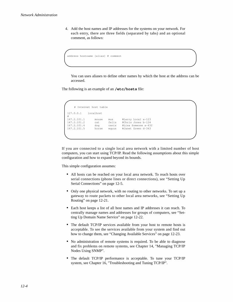
Network Administration
12-4
4. Add the host names and IP addresses for the systems on your network. Foreach entry, there are three fields (separated by tabs) and an optionalcomment, as follows:
You can uses aliases to define other names by which the host at the address can beaccessed.
The following is an example of an /etc/hosts file:
If you are connected to a single local area network with a limited number of hostcomputers, you can start using TCP/IP. Read the following assumptions about this simpleconfiguration and how to expand beyond its bounds.
This simple configuration assumes:
• All hosts can be reached on your local area network. To reach hosts overserial connections (phone lines or direct connections), see “Setting UpSerial Connections” on page 12-5.
• Only one physical network, with no routing to other networks. To set up agateway to route packets to other local area networks, see “Setting UpRouting” on page 12-21.
• Each host keeps a list of all host names and IP addresses it can reach. Tocentrally manage names and addresses for groups of computers, see “Set-ting Up Domain Name Service” on page 12-22.
• The default TCP/IP services available from your host to remote hosts isacceptable. To see the services available from your system and find outhow to change them, see “Changing Available Services” on page 12-23.
• No administration of remote systems is required. To be able to diagnoseand fix problems on remote systems, see Chapter 14, "Managing TCP/IPNodes Using SNMP".
• The default TCP/IP performance is acceptable. To tune your TCP/IPsystem, see Chapter 16, "Troubleshooting and Tuning TCP/IP".
address hostname [alias] # comment
# Internet host table
127.0.0.1 localhost#147.2.101.1 mouse mus #Larry Local a-123147.2.101.2 cat felis #Chris Jones b-124147.2.101.4 dog canis #Lisa Someone a-432147.2.101.5 horse equus #Janet Green d-343
Setting Up TCP/IP
12-5
Expanding Your TCP/IP Network 12
Only the smallest, most self-contained network configurations will find the proceduredescribed in “Creating a Simple TCP/IP Network” on page 12-3 sufficient. The followingsections lead you into more advanced configuration topics.
Setting Up Serial Connections 12
If you want to reach a remote system that is not connected to your LAN, but is reachableover serial lines (telephone or direct connection), you have two methods from which youcan choose: Serial Line IP (SLIP) and Point-to-Point Protocol (PPP).
SLIP lets you use direct serial line connections to connect to remote systems with TCP/IP.PPP allows you to connect to remote systems over telephone lines, direct connections, orany other types of serial connection you can configure using the standard UNIX uucpfacility.
Configuring Point-to-Point Protocol Connections (PPP) 12
The procedure below describes how to set up a ppp connection between two systems:SystemA and SystemB . SystemA is configured to receive incoming ppp calls;SystemB is configured to make outgoing ppp calls. Follow the two procedures to set upppp communications between two systems.
NOTE
If you are using PPP to connect to a SCO TCP/IP, there are severalparameters that must be turned on. The parameters are: DLCAddress Control Field Compression, IP Address negotiation, OldIP address negotiation (RFC1172), Van Jacobson TCP headercompression, and Compatibility with old PPP. You can set theseparameters during the pppconf procedure. The resulting entry inthe /etc/inet/ppphosts file would look like the following:
137.65.208.51 - remote1 idle=30 old ipaddrrfc1172addr VJ accomp
where 137.65.208.51 is replaced by your local ppp IPaddress and remote1 is replaced by the name of the remote pppsystem as it appears in your /etc/uucp/Systems file. (Theidle=30 is not required, but is a good idea so your modemconnection times out after a set number of minutes of inactivity.)
Network Administration
12-6
Configuring SystemA (incoming ppp connection) 12
To configure a system for incoming ppp calls, do the following:
1. Configure an incoming uucp connection. Any valid uucp connection isacceptable. In the example below, we used a ZyXEL Hayes-compatiblemodem configured to accept incoming calls and transfer data at 9600 bps.
a. Open a Terminal Window.
b. As root user, add the following entries to /etc/uucp/Devicesfor the serial port 2 (use tty00h for serial port 1):
We use the tty01h , rather than tty01 , because tty01h lets us use hard-ware flow control.
c. Connect the modem to the serial port 2.
d. Change the tty settings in your Terminal window to incorporate thefollowing:
(The reason these values are important is that when you cu directlyto the port later, cu uses the current tty settings to make theconnection. cu might change your modem settings automaticallybased on these settings. Note that you may want to add this entry toyour .profile file.)
e. Type the following from the Terminal window as root user tochange the settings on the modem:
These settings may vary for each modem you use. In our case, ATS00=001 turns on auto answer, AT S15=130 sets the parity
Direct tty01h - 9600 direct_modem
stty -parenb cs8 9600
cu -l tty01h AT S00=001AT S15=130AT S20=7ATQ2ATQ1 AT&W~.
Setting Up TCP/IP
12-7
properly, and AT S20=7 sets the line speed to 9600. Then ATQ1 andATQ2 set the modem to not send certain strings that confuse the loginprocess later. The setting AT&W writes the change to the modem and~. returns you to the shell. These settings may be lost if you turn offthe modem later. To check that the settings are correct, cu to themodem again and type AT&V0.
Read your modem manual to set your settings in a similar fashion!The settings you should watch for include serial port speed locking,hardware or software flow control setup (most modems do not do thisby default), DCD, DTR and DSR handshake configuration,transmission mode selection (V32.bis, V42.bis, and so on) resultcode set, result code suppression (for answering modem), verbosemode, auto answer, character size and parity (for XON/XOFF recog-nition) and EEprom write command.
f. Change the 9600 entry in the /etc/ttydefs file to disable parity(-parenb ) and use 8-bit characters (cs8 ) read as follows:
g. Configure a process to listen to the serial port 2 by typing thefollowing from a Terminal window as root user:
h. Edit the _pmtab file in /etc/saf/ttymon1 , changing the deviceto /dev/tty01h and the word auto to read 9600 . (If thettymon1 directory is not there, check other directories at that levelfor the entry shown below.)
9600: 9600 opost onlcr tab3 ignpar ixon ixany-parenb istrip echo echoe erase echok isig cs8 cread :9600 opost onlcr sane tab3 ignpar ixon ixany -parenbistrip echo echoe erase echok isig cs8 cread ::4800
/usr/X/adm/pmadm
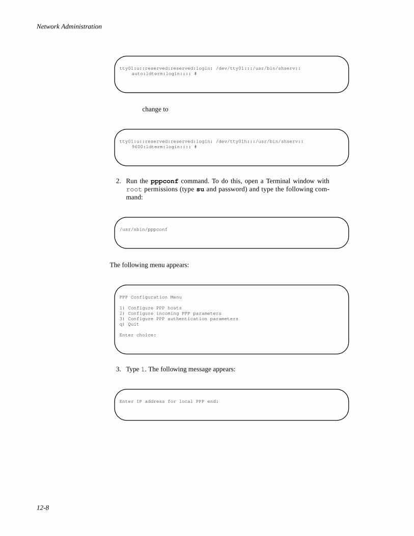
Network Administration
12-8
change to
2. Run the pppconf command. To do this, open a Terminal window withroot permissions (type su and password) and type the following com-mand:
The following menu appears:
3. Type 1. The following message appears:
tty01:u::reserved:reserved:login: /dev/tty01:::/usr/bin/shserv::auto:ldterm:login:::: #
tty01:u::reserved:reserved:login: /dev/tty01h:::/usr/bin/shserv::9600:ldterm:login:::: #
/usr/sbin/pppconf
PPP Configuration Menu
1) Configure PPP hosts2) Configure incoming PPP parameters3) Configure PPP authentication parametersq) Quit
Enter choice:
Enter IP address for local PPP end:

Setting Up TCP/IP
12-9
4. Type the local system's IP address (for example, 128.212.44.44 ). Thefollowing message appears:
5. Type the remote system's IP address (for example, 128.212.44.90 ).The following message appears:
6. Press Enter to use the current netmask for your system (for example,255.255.255.0 ). The following message appears:
7. Type the uucp system name for the remote host you set up in Step 1. (Inthis case, because ppp is not making outgoing calls from this host, type adash ('- ') to make the entry null.) If you specified a name other than null ('-'), the following message appears:
8. Type n to not add any additional parameters. (The parameters you could setat this point only apply to outgoing ppp connections.) If you type n, thefollowing message appears:
9. Type y to add the remote host to /etc/hosts . The following messageappears:
Enter IP address for remote PPP end:
Enter netmask [default]:
The UUCP name is used by PPP to dial into the remote system.If a UUCP name is not specified, outgoing calls will be disabled.Enter UUCP name ("-" for null):
Do you want to specify PPP negotiation parameters? (y/n):
Do you want to add an entry for the remote hostto /etc/hosts? (y/n):
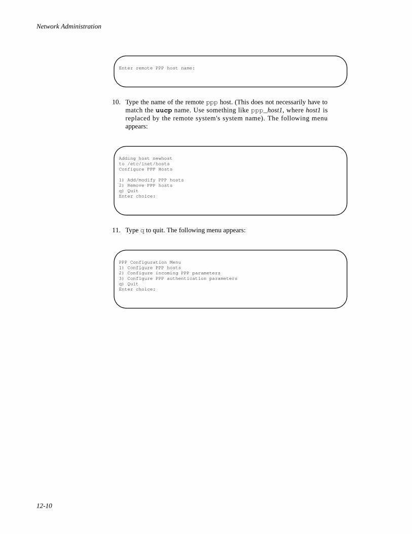
Network Administration
12-10
10. Type the name of the remote ppp host. (This does not necessarily have tomatch the uucp name. Use something like ppp_ host1, where host1 isreplaced by the remote system's system name). The following menuappears:
11. Type q to quit. The following menu appears:
Enter remote PPP host name:
Adding host newhostto /etc/inet/hostsConfigure PPP Hosts
1) Add/modify PPP hosts2) Remove PPP hostsq) QuitEnter choice:
PPP Configuration Menu1) Configure PPP hosts2) Configure incoming PPP parameters3) Configure PPP authentication parametersq) QuitEnter choice:
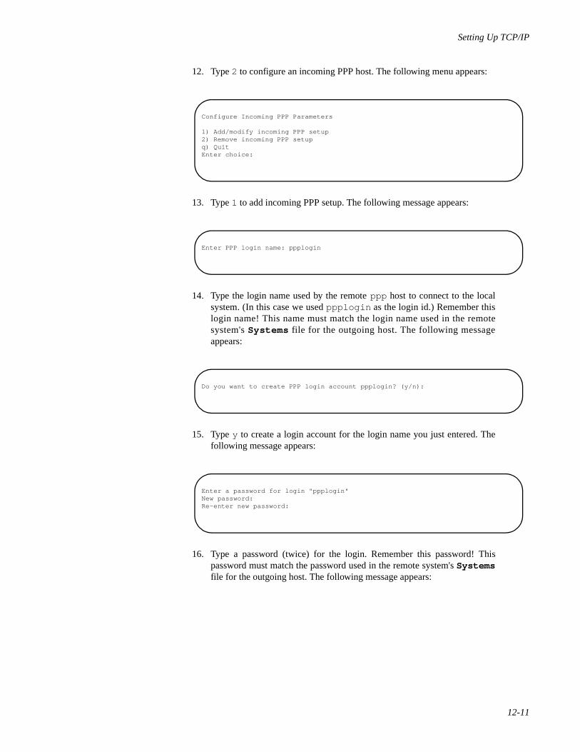
Setting Up TCP/IP
12-11
12. Type 2 to configure an incoming PPP host. The following menu appears:
13. Type 1 to add incoming PPP setup. The following message appears:
14. Type the login name used by the remote ppp host to connect to the localsystem. (In this case we used ppplogin as the login id.) Remember thislogin name! This name must match the login name used in the remotesystem's Systems file for the outgoing host. The following messageappears:
15. Type y to create a login account for the login name you just entered. Thefollowing message appears:
16. Type a password (twice) for the login. Remember this password! Thispassword must match the password used in the remote system's Systemsfile for the outgoing host. The following message appears:
Configure Incoming PPP Parameters
1) Add/modify incoming PPP setup2) Remove incoming PPP setupq) QuitEnter choice:
Enter PPP login name: ppplogin
Do you want to create PPP login account ppplogin? (y/n):
Enter a password for login "ppplogin"New password:Re-enter new password:
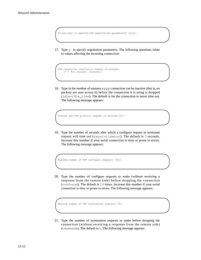
Network Administration
12-12
17. Type y to specify negotiation parameters. The following questions relateto values affecting the incoming connection:
18. Type in the number of minutes a ppp connection can be inactive (that is, nopackets are sent across it) before the connection it is using is dropped(idle=idle_time ). The default is for the connection to never time out.The following message appears:
19. Type the number of seconds after which a configure request or terminaterequest will time out (tmout=timeout ). The default is 3 seconds.Increase this number if your serial connection is slow or prone to errors.The following message appears:
20. Type the number of configure requests to make (without receiving aresponse from the remote side) before dropping the connection(conf=num ). The default is 10 times. Increase this number if your serialconnection is slow or prone to errors. The following message appears:
21. Type the number of termination requests to make before dropping theconnection (without receiving a response from the remote side)(term=num ). The default is 2. The following message appears:
Do you want to specify PPP negotiation parameters? (y/n):
PPP connection inactivity timeout in minutes("-" for forever) [forever]:
Timeout per PPP protocol request in seconds [3]:
Maximum number of PPP configure requests [10]:
Maximum number of PPP termination requests [2]:
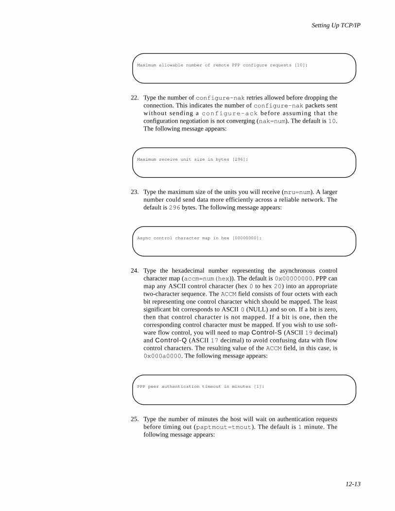
Setting Up TCP/IP
12-13
22. Type the number of configure-nak retries allowed before dropping theconnection. This indicates the number of configure-nak packets sentwithout sending a configure-ack before assuming that theconfiguration negotiation is not converging (nak=num). The default is 10.The following message appears:
23. Type the maximum size of the units you will receive (mru=num). A largernumber could send data more efficiently across a reliable network. Thedefault is 296 bytes. The following message appears:
24. Type the hexadecimal number representing the asynchronous controlcharacter map (accm=num(hex )). The default is 0x00000000 . PPP canmap any ASCII control character (hex 0 to hex 20 ) into an appropriatetwo-character sequence. The ACCM field consists of four octets with eachbit representing one control character which should be mapped. The leastsignificant bit corresponds to ASCII 0 (NULL) and so on. If a bit is zero,then that control character is not mapped. If a bit is one, then thecorresponding control character must be mapped. If you wish to use soft-ware flow control, you will need to map Control-S (ASCII 19 decimal)and Control-Q (ASCII 17 decimal) to avoid confusing data with flowcontrol characters. The resulting value of the ACCM field, in this case, is0x000a0000 . The following message appears:
25. Type the number of minutes the host will wait on authentication requestsbefore timing out (paptmout=tmout ). The default is 1 minute. Thefollowing message appears:
Maximum allowable number of remote PPP configure requests [10]:
Maximum receive unit size in bytes [296]:
Async control character map in hex [00000000]:
PPP peer authentication timeout in minutes [1]:
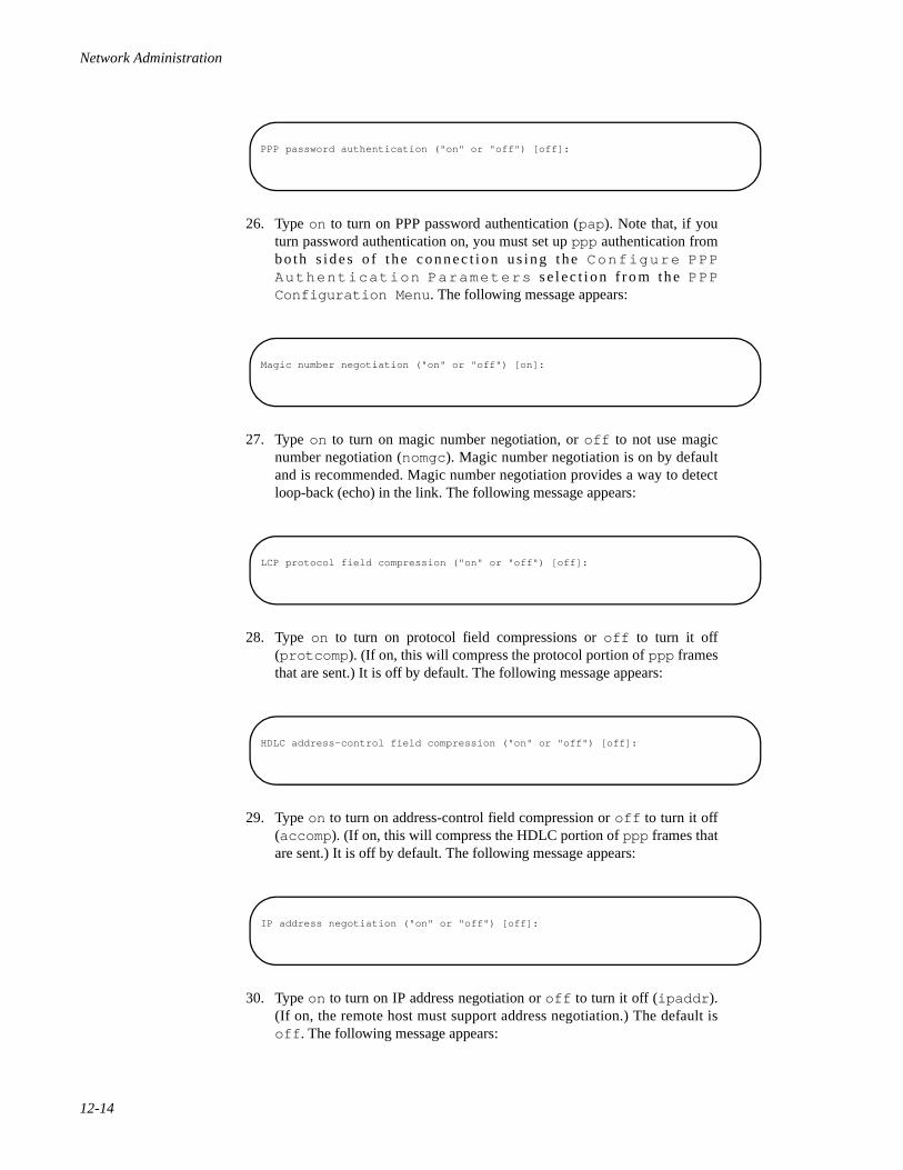
Network Administration
12-14
26. Type on to turn on PPP password authentication (pap ). Note that, if youturn password authentication on, you must set up ppp authentication fromboth s ides o f the connec t ion us ing the Conf igure PPPAuthent icat ion Parameters se lec t i on f ro m the PPPConfiguration Menu . The following message appears:
27. Type on to turn on magic number negotiation, or off to not use magicnumber negotiation (nomgc). Magic number negotiation is on by defaultand is recommended. Magic number negotiation provides a way to detectloop-back (echo) in the link. The following message appears:
28. Type on to turn on protocol field compressions or off to turn it off(protcomp ). (If on, this will compress the protocol portion of ppp framesthat are sent.) It is off by default. The following message appears:
29. Type on to turn on address-control field compression or off to turn it off(accomp). (If on, this will compress the HDLC portion of ppp frames thatare sent.) It is off by default. The following message appears:
30. Type on to turn on IP address negotiation or off to turn it off (ipaddr ).(If on, the remote host must support address negotiation.) The default isoff . The following message appears:
PPP password authentication ("on" or "off") [off]:
Magic number negotiation ("on" or "off") [on]:
LCP protocol field compression ("on" or "off") [off]:
HDLC address-control field compression ("on" or "off") [off]:
IP address negotiation ("on" or "off") [off]:
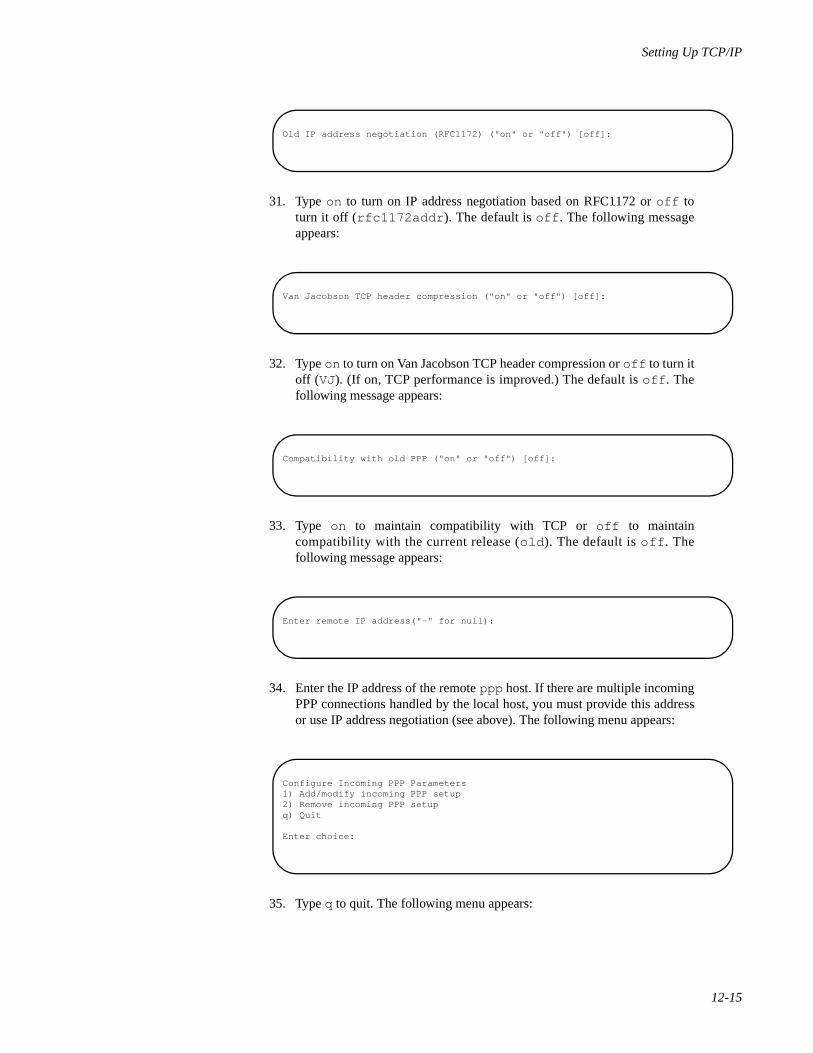
Setting Up TCP/IP
12-15
31. Type on to turn on IP address negotiation based on RFC1172 or off toturn it off (rfc1172addr ). The default is off . The following messageappears:
32. Type on to turn on Van Jacobson TCP header compression or off to turn itoff (VJ). (If on, TCP performance is improved.) The default is off . Thefollowing message appears:
33. Type on to maintain compatibility with TCP or off to maintaincompatibility with the current release (old ). The default is off . Thefollowing message appears:
34. Enter the IP address of the remote ppp host. If there are multiple incomingPPP connections handled by the local host, you must provide this addressor use IP address negotiation (see above). The following menu appears:
35. Type q to quit. The following menu appears:
Old IP address negotiation (RFC1172) ("on" or "off") [off]:
Van Jacobson TCP header compression ("on" or "off") [off]:
Compatibility with old PPP ("on" or "off") [off]:
Enter remote IP address("-" for null):
Configure Incoming PPP Parameters1) Add/modify incoming PPP setup2) Remove incoming PPP setupq) Quit
Enter choice:
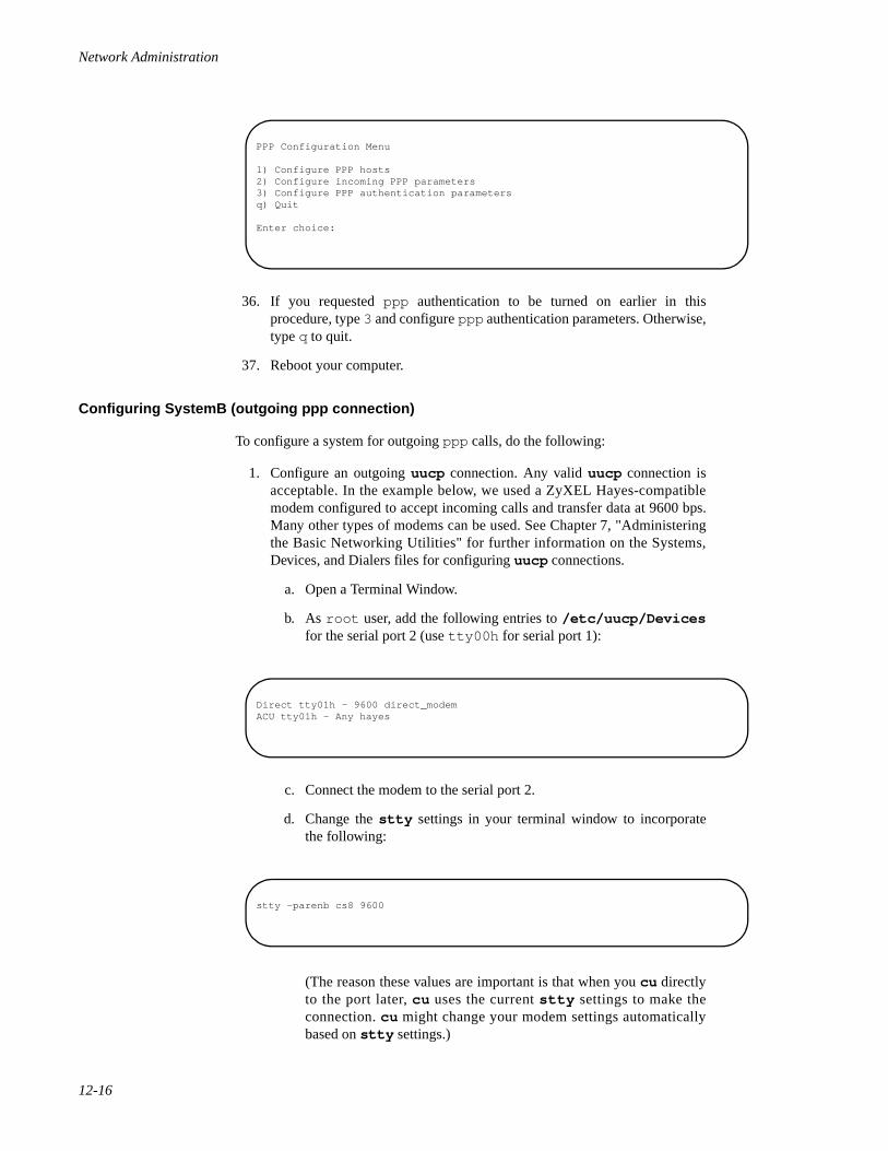
Network Administration
12-16
36. If you requested ppp authentication to be turned on earlier in thisprocedure, type 3 and configure ppp authentication parameters. Otherwise,type q to quit.
37. Reboot your computer.
Configuring SystemB (outgoing ppp connection) 12
To configure a system for outgoing ppp calls, do the following:
1. Configure an outgoing uucp connection. Any valid uucp connection isacceptable. In the example below, we used a ZyXEL Hayes-compatiblemodem configured to accept incoming calls and transfer data at 9600 bps.Many other types of modems can be used. See Chapter 7, "Administeringthe Basic Networking Utilities" for further information on the Systems,Devices, and Dialers files for configuring uucp connections.
a. Open a Terminal Window.
b. As root user, add the following entries to /etc/uucp/Devicesfor the serial port 2 (use tty00h for serial port 1):
c. Connect the modem to the serial port 2.
d. Change the stty settings in your terminal window to incorporatethe following:
(The reason these values are important is that when you cu directlyto the port later, cu uses the current stty settings to make theconnection. cu might change your modem settings automaticallybased on stty settings.)
PPP Configuration Menu
1) Configure PPP hosts2) Configure incoming PPP parameters3) Configure PPP authentication parametersq) Quit
Enter choice:
Direct tty01h - 9600 direct_modemACU tty01h - Any hayes
stty -parenb cs8 9600
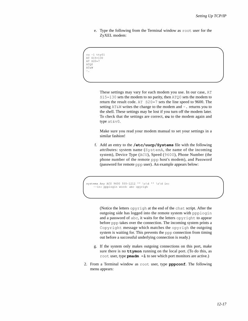
Setting Up TCP/IP
12-17
e. Type the following from the Terminal window as root user for theZyXEL modem:
These settings may vary for each modem you use. In our case, ATS15=130 sets the modem to no parity, then ATQ0 sets the modem toreturn the result code. AT S20=7 sets the line speed to 9600. Thesetting AT&W writes the change to the modem and ~. returns you tothe shell. These settings may be lost if you turn off the modem later.To check that the settings are correct, cu to the modem again andtype at&v0 .
Make sure you read your modem manual to set your settings in asimilar fashion!
f. Add an entry to the /etc/uucp/Systems file with the followingattributes: system name (SystemA , the name of the incomingsystem), Device Type (ACU), Speed (9600 ), Phone Number (thephone number of the remote ppp host's modem), and Password(password for remote ppp user). An example appears below:
(Notice the letters opyrigh at the end of the chat script. After theoutgoing side has logged into the remote system with ppploginand a password of abc , it waits for the letters opyright to appearbefore ppp takes over the connection. The incoming system prints aCopyright message which matches the opyrigh the outgoingsystem is waiting for. This prevents the ppp connection from timingout before a successful underlying connection is ready.)
g. If the system only makes outgoing connections on this port, makesure there is no ttymon running on the local port. (To do this, asroot user, type pmadm -l to see which port monitors are active.)
2. From a Terminal window as root user, type pppconf . The followingmenu appears:
cu -l tty01 AT S15=130AT S20=7ATQ0 AT&W ~.
systema Any ACU 9600 555-1212 "" \r\d "" \r\d in:--in: ppplogin word: abc opyrigh
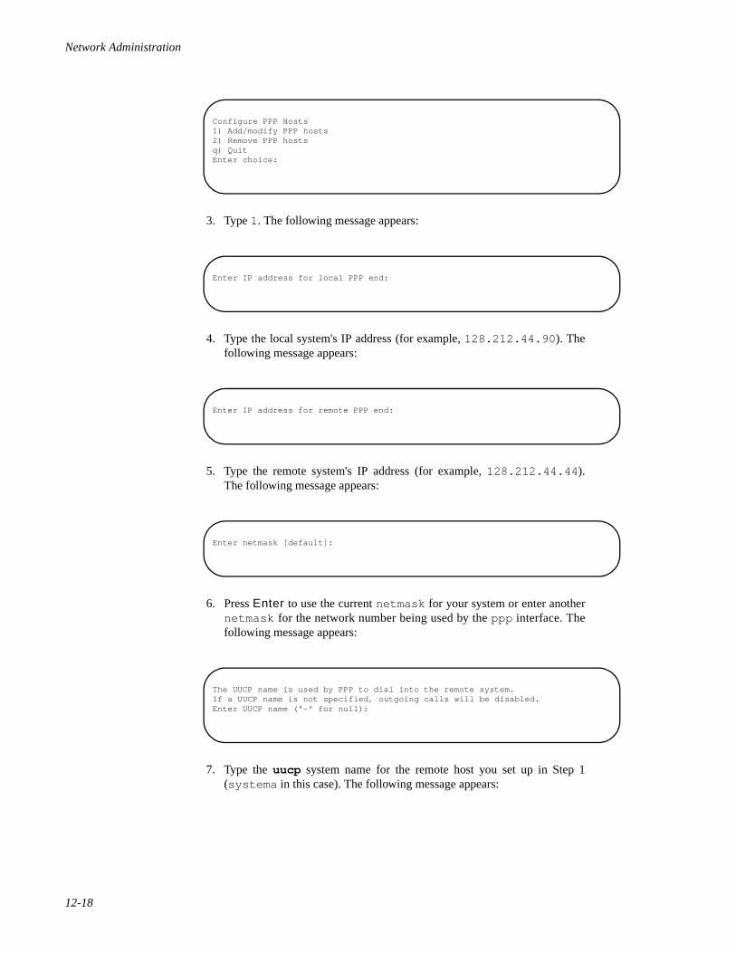
Network Administration
12-18
3. Type 1. The following message appears:
4. Type the local system's IP address (for example, 128.212.44.90 ). Thefollowing message appears:
5. Type the remote system's IP address (for example, 128.212.44.44 ).The following message appears:
6. Press Enter to use the current netmask for your system or enter anothernetmask for the network number being used by the ppp interface. Thefollowing message appears:
7. Type the uucp system name for the remote host you set up in Step 1(systema in this case). The following message appears:
Configure PPP Hosts1) Add/modify PPP hosts2) Remove PPP hostsq) QuitEnter choice:
Enter IP address for local PPP end:
Enter IP address for remote PPP end:
Enter netmask [default]:
The UUCP name is used by PPP to dial into the remote system.If a UUCP name is not specified, outgoing calls will be disabled.Enter UUCP name ("-" for null):
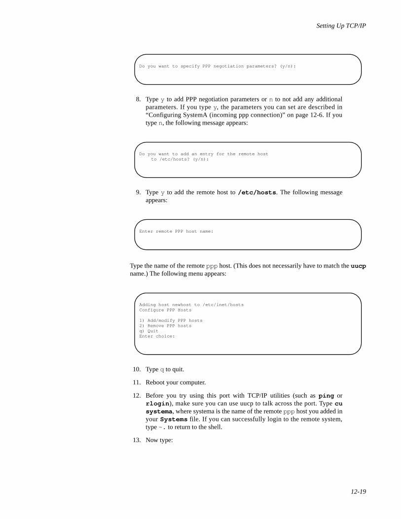
Setting Up TCP/IP
12-19
8. Type y to add PPP negotiation parameters or n to not add any additionalparameters. If you type y, the parameters you can set are described in“Configuring SystemA (incoming ppp connection)” on page 12-6. If youtype n, the following message appears:
9. Type y to add the remote host to /etc/hosts . The following messageappears:
Type the name of the remote ppp host. (This does not necessarily have to match the uucpname.) The following menu appears:
10. Type q to quit.
11. Reboot your computer.
12. Before you try using this port with TCP/IP utilities (such as ping orrlogin ), make sure you can use uucp to talk across the port. Type cusystema , where systema is the name of the remote ppp host you added inyour Systems file. If you can successfully login to the remote system,type ~. to return to the shell.
13. Now type:
Do you want to specify PPP negotiation parameters? (y/n):
Do you want to add an entry for the remote hostto /etc/hosts? (y/n):
Enter remote PPP host name:
Adding host newhost to /etc/inet/hostsConfigure PPP Hosts
1) Add/modify PPP hosts2) Remove PPP hostsq) QuitEnter choice:
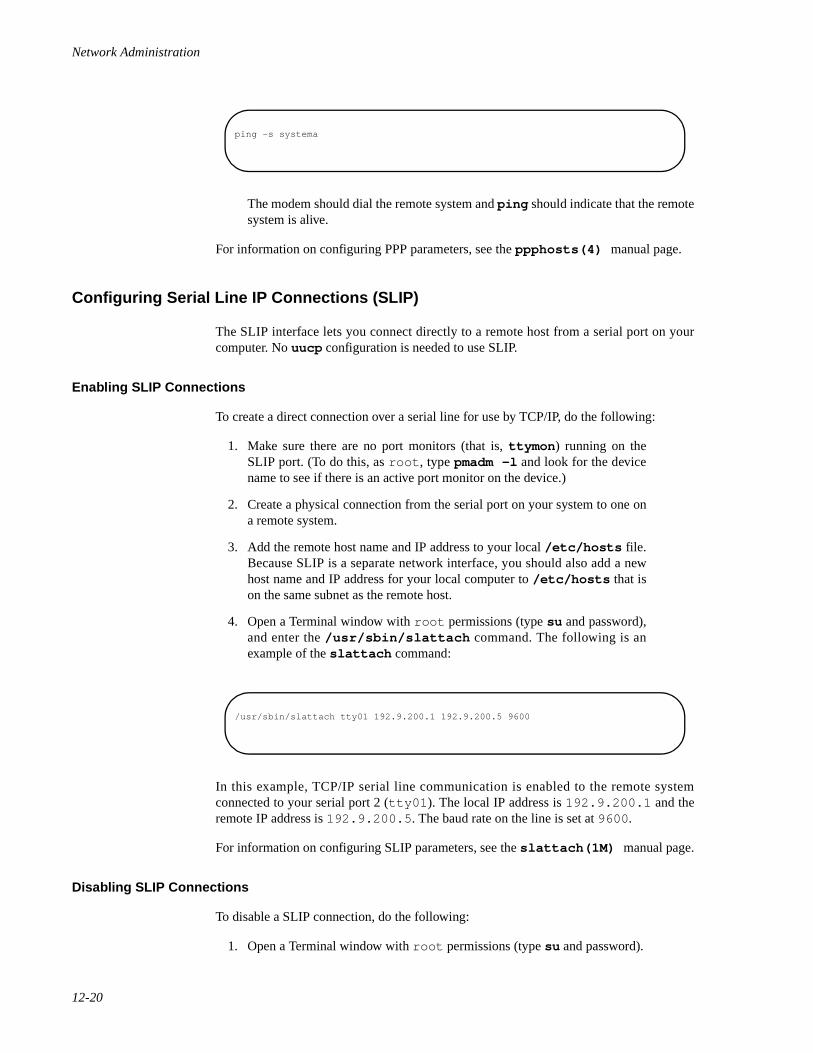
Network Administration
12-20
The modem should dial the remote system and ping should indicate that the remotesystem is alive.
For information on configuring PPP parameters, see the ppphosts(4) manual page.
Configuring Serial Line IP Connections (SLIP) 12
The SLIP interface lets you connect directly to a remote host from a serial port on yourcomputer. No uucp configuration is needed to use SLIP.
Enabling SLIP Connections 12
To create a direct connection over a serial line for use by TCP/IP, do the following:
1. Make sure there are no port monitors (that is, ttymon ) running on theSLIP port. (To do this, as root , type pmadm -l and look for the devicename to see if there is an active port monitor on the device.)
2. Create a physical connection from the serial port on your system to one ona remote system.
3. Add the remote host name and IP address to your local /etc/hosts file.Because SLIP is a separate network interface, you should also add a newhost name and IP address for your local computer to /etc/hosts that ison the same subnet as the remote host.
4. Open a Terminal window with root permissions (type su and password),and enter the /usr/sbin/slattach command. The following is anexample of the slattach command:
In this example, TCP/IP serial line communication is enabled to the remote systemconnected to your serial port 2 (tty01 ). The local IP address is 192.9.200.1 and theremote IP address is 192.9.200.5 . The baud rate on the line is set at 9600 .
For information on configuring SLIP parameters, see the slattach(1M) manual page.
Disabling SLIP Connections 12
To disable a SLIP connection, do the following:
1. Open a Terminal window with root permissions (type su and password).
ping -s systema
/usr/sbin/slattach tty01 192.9.200.1 192.9.200.5 9600
Setting Up TCP/IP
12-21
2. Kill the running slattach process.
3. Manually remove the routing information associated with the SLIPconnection using the following command:
In this example, 192.9.200.5 is the IP address of the remote host and 192.9.200 isthe local IP address as your computer is known to the SLIP interface.
Setting Up Routing 12
As your network expands, you will want to reach hosts that are connected to other net-works. You can connect your LAN to another LAN by designating one of your systems asa gateway to do routing. Likewise, if a computer on your LAN has a connection to aremote SLIP or PPP host, you can use that computer to route packets to the remote hostfrom other hosts on your LAN.
In a simple case, you may have two local area networks in your building. You designateone system as a router. You must use the procedure described below to set up the gatewaysystem and all client systems as follows:
1. On the gateway system do the following:
a. Install and configure two network interface cards on the system: oneconnecting to the first network and one to the second. (See thecommand /etc/confnet.d/configure and the /etc/confnet.d/inet/interface file.)
b. Assign two names and network addresses to the routing system.Assign different names for each network. (See the /etc/hostsfile.)
c. Configure the router to route packets between the two networks. (Seethe daemon in.routed , as well as the networks and gatewaysfiles, and Chapter 13, "Setting Up Routers and Subnetworks".)
2. On the client system, configure the router daemon so packets for systemsnot on the local network are directed to the router. Or, instead, you couldhard code the location of the router.
Complete descriptions and procedures for setting up a router are contained in Chapter 13,"Setting Up Routers and Subnetworks".
/usr/sbin/route delete 192.9.200.5 192.9.200.1
Network Administration
12-22
Setting Up Domain Name Service 12
If you want to communicate with other hosts on the Internet, you must set up domainname service (DNS). Even if you are not connecting to the Internet, in an organizationwhere systems are constantly being added and changed, it is often inconvenient for everycomputer to have its own complete list of system names.
By setting up domain name service, you centralize the administration of system namesand addresses. When a system tries to communicate with another system, it checks thename server for the remote system's address.
Once you have obtained a domain name from the NIC for your network and figured out ascheme for using subdomains, use the procedure described below to set up domain nameservice for your domain:
1. On the client systems do the following:
a. Configure the addresses for each domain name server the client canreach . (See the /e tc / reso lv .con f f i l e and theresolv.conf(4) manual page.)
b. Make sure all transport providers that provide IP connections haveDNS name-to-address routing defined. (See the /etc/netconfigfile and the netconfig(4) manual page.)
2. On the domain name server systems do the following:
a. Configure domain name server addresses and name-to-addressresolving, as you would for a client system.
b. Configure the boot and data files for the name service daemon (seethe named(1M) manual page).
c. Start up the name service daemon (in.named ) in the system's Inter-net start-up script (/etc/inet/rc.inet ). If named.boot isconfigured, in.named will start automatically.
Complete descriptions and procedures for setting up domain name service are contained inChapter 15, "Using Domain Name Service with TCP/IP". Descriptions of domains andsubdomains are contained in Chapter 11, "Introduction to Administering TCP/IP Net-works".
Setting Up Subnetworks 12
To be able to join together several physical networks together under one network ID, youcan divide up your assigned pool of IP addresses into subnets. See Chapter 11, "Introduc-tion to Administering TCP/IP Networks" for descriptions of IP addresses. See Chapter 13,"Setting Up Routers and Subnetworks" for descriptions of subnetwork configuration.
Setting Up TCP/IP
12-23
Changing Available Services 12
A standard set of services is available on your TCP/IP system when it is installed. Asrequests come into your system on particular TCP/IP or UDP ports, your system takes therequests and responds by fulfilling or rejecting the service requests.
TCP/IP services your system knows about are contained in the /etc/inet/servicesfile. The daemon processes that handle requests for those services are listed in the file/etc/inet/inetd.conf .
Examples of services provided by TCP/IP that can be turned off and on include thefollowing commands: ftp , telnet , and named. Some services, such as ntp and snmp,are turned on automatically if configuration files are set up for these services. Someservices are not turned on by default.
The following procedure shows how you would allow a remote system to run the fingercommand to check on users on your system:
1. Open the /etc/inet/inetd.conf file for editing as root user.
2. Remove the comment character (`#') from in front of the line containingthe fingerd daemon, so it appears as follows:
3. Save and exit the file.
4. Type the following from the command line, as root user, to obtain theprocess number of the inetd daemon:
5. Using the process id of the inetd daemon, type the following command:
where pid is replaced by the process ID of the running inetd daemon.
A remote user could now run finger to get information about users on your system. Youdon't have to reboot your system. (Note that fingerd , as well as other services youallow, may pose some security risks.)
finger stream tcp nowait nobody /usr/sbin/in.fingerd in.fingerd
# ps -ef | grep inetd
# kill -HUP pid
Network Administration
12-24
Managing Remote Systems 12
Using Simple Network Management Protocol (SNMP), you can monitor and control otherTCP/IP systems from your system. Information on configuring and using SNMP iscontained in Chapter 14, "Managing TCP/IP Nodes Using SNMP".
Synchronizing Time 12
Time clocks on your computers will drift apart over time. To ensure that time issynchronized on the computers on your network, follow procedures described inChapter 19, "Network Time Synchronization".
Maintaining Security 12
The OS includes various user programs that enable network users to log in to remotesystems (rlogin ), create and use a shell on a remote machine (rsh ), and copy files toand from a remote machine (rcp ).
For a remote user to use the above commands to access your system, he or she must have auser account on your system. Although remote users can log in to your machine once theyhave entries in your password database, they cannot run certain remote processes (such asrsh and rcp ) unless their machines are listed in the /etc/hosts.equiv file, or theuser's .rhosts file, located in the user's home directory. In addition to allowing remoteusers to run certain remote processes on your machine, these files grant users access toyour machine without their having to supply passwords.
This section explains how your system uses the hosts.equiv and .rhosts files, thengives you instructions for setting up and maintaining these files.
Administering the hosts.equiv and .rhosts Files 12
On a TCP/IP-based network, security is implemented at two levels: first, at the host level,and second, at the user level.
The /etc/hosts.equiv file is a general database that controls access at the host level.The .rhosts file controls access to your machine at the user level. It is a file located inthe home directory of a specific remote user on your machine, and it is used to allow ordeny access to that specific user. There may be multiple instances of .rhosts on yourmachine, one for each remote user with a home directory.
When a remote user attempts to log in to your machine, the security-checking processgoes like this:
• A remote user initiates an rlogin , and the rlogin daemon on yourmachine checks for the user's user name in the password database. If noentry is found, the remote user is denied access.
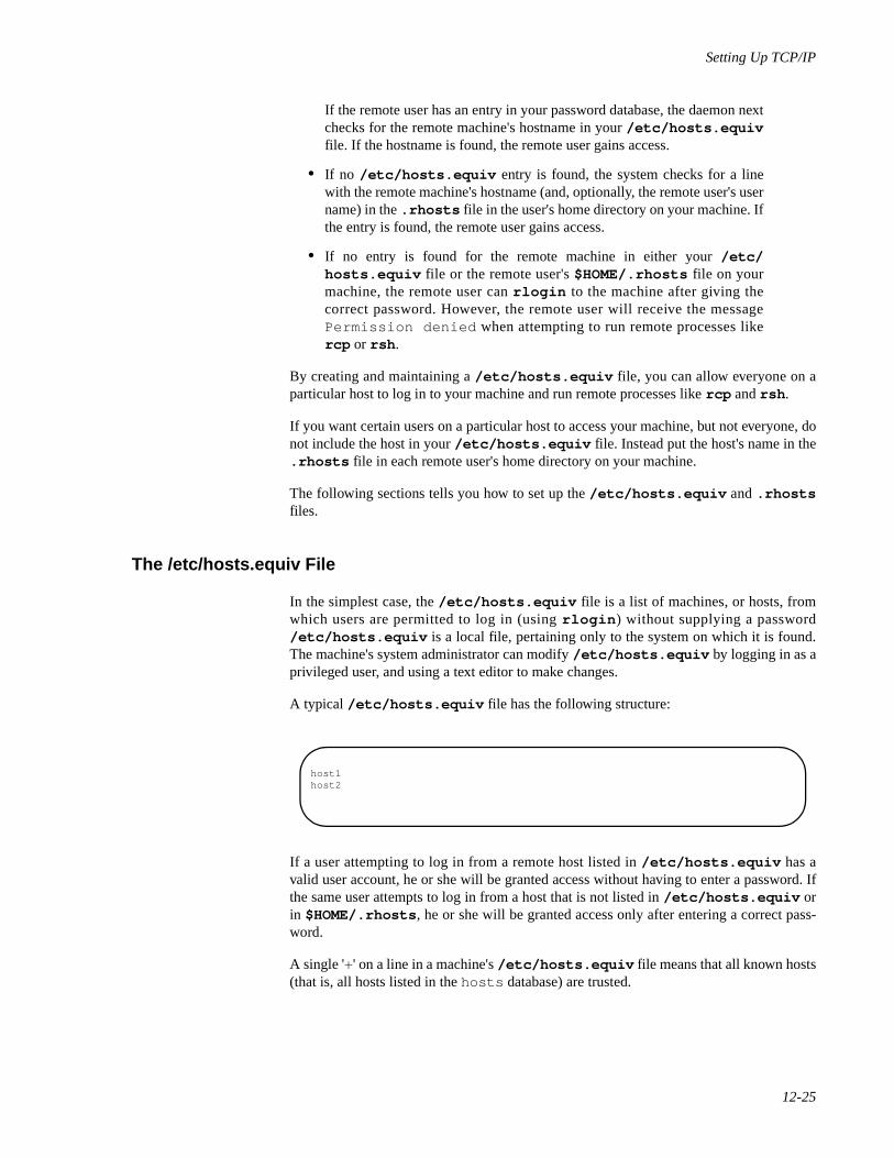
Setting Up TCP/IP
12-25
If the remote user has an entry in your password database, the daemon nextchecks for the remote machine's hostname in your /etc/hosts.equivfile. If the hostname is found, the remote user gains access.
• If no /etc/hosts.equiv entry is found, the system checks for a linewith the remote machine's hostname (and, optionally, the remote user's username) in the .rhosts file in the user's home directory on your machine. Ifthe entry is found, the remote user gains access.
• If no entry is found for the remote machine in either your /etc/hosts.equiv file or the remote user's $HOME/.rhosts file on yourmachine, the remote user can rlogin to the machine after giving thecorrect password. However, the remote user will receive the messagePermission denied when attempting to run remote processes likercp or rsh .
By creating and maintaining a /etc/hosts.equiv file, you can allow everyone on aparticular host to log in to your machine and run remote processes like rcp and rsh .
If you want certain users on a particular host to access your machine, but not everyone, donot include the host in your /etc/hosts.equiv file. Instead put the host's name in the.rhosts file in each remote user's home directory on your machine.
The following sections tells you how to set up the /etc/hosts.equiv and .rhostsfiles.
The /etc/hosts.equiv File 12
In the simplest case, the /etc/hosts.equiv file is a list of machines, or hosts, fromwhich users are permitted to log in (using rlogin ) without supplying a password/etc/hosts.equiv is a local file, pertaining only to the system on which it is found.The machine's system administrator can modify /etc/hosts.equiv by logging in as aprivileged user, and using a text editor to make changes.
A typical /etc/hosts.equiv file has the following structure:
If a user attempting to log in from a remote host listed in /etc/hosts.equiv has avalid user account, he or she will be granted access without having to enter a password. Ifthe same user attempts to log in from a host that is not listed in /etc/hosts.equiv orin $HOME/.rhosts , he or she will be granted access only after entering a correct pass-word.
A single '+' on a line in a machine's /etc/hosts.equiv file means that all known hosts(that is, all hosts listed in the hosts database) are trusted.
host1 host2
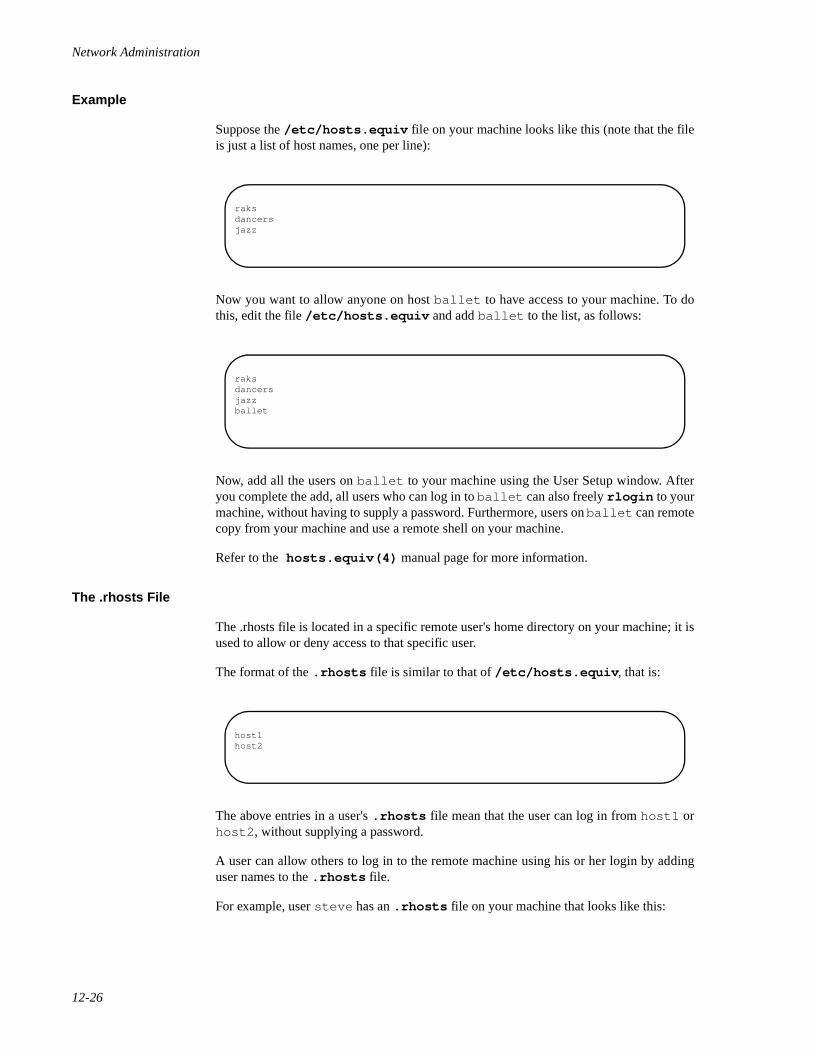
Network Administration
12-26
Example 12
Suppose the /etc/hosts.equiv file on your machine looks like this (note that the fileis just a list of host names, one per line):
Now you want to allow anyone on host ballet to have access to your machine. To dothis, edit the file /etc/hosts.equiv and add ballet to the list, as follows:
Now, add all the users on ballet to your machine using the User Setup window. Afteryou complete the add, all users who can log in to ballet can also freely rlogin to yourmachine, without having to supply a password. Furthermore, users on ballet can remotecopy from your machine and use a remote shell on your machine.
Refer to the hosts.equiv(4) manual page for more information.
The .rhosts File 12
The .rhosts file is located in a specific remote user's home directory on your machine; it isused to allow or deny access to that specific user.
The format of the .rhosts file is similar to that of /etc/hosts.equiv , that is:
The above entries in a user's .rhosts file mean that the user can log in from host1 orhost2 , without supplying a password.
A user can allow others to log in to the remote machine using his or her login by addinguser names to the .rhosts file.
For example, user steve has an .rhosts file on your machine that looks like this:
raksdancersjazz
raksdancersjazzballet
host1host2
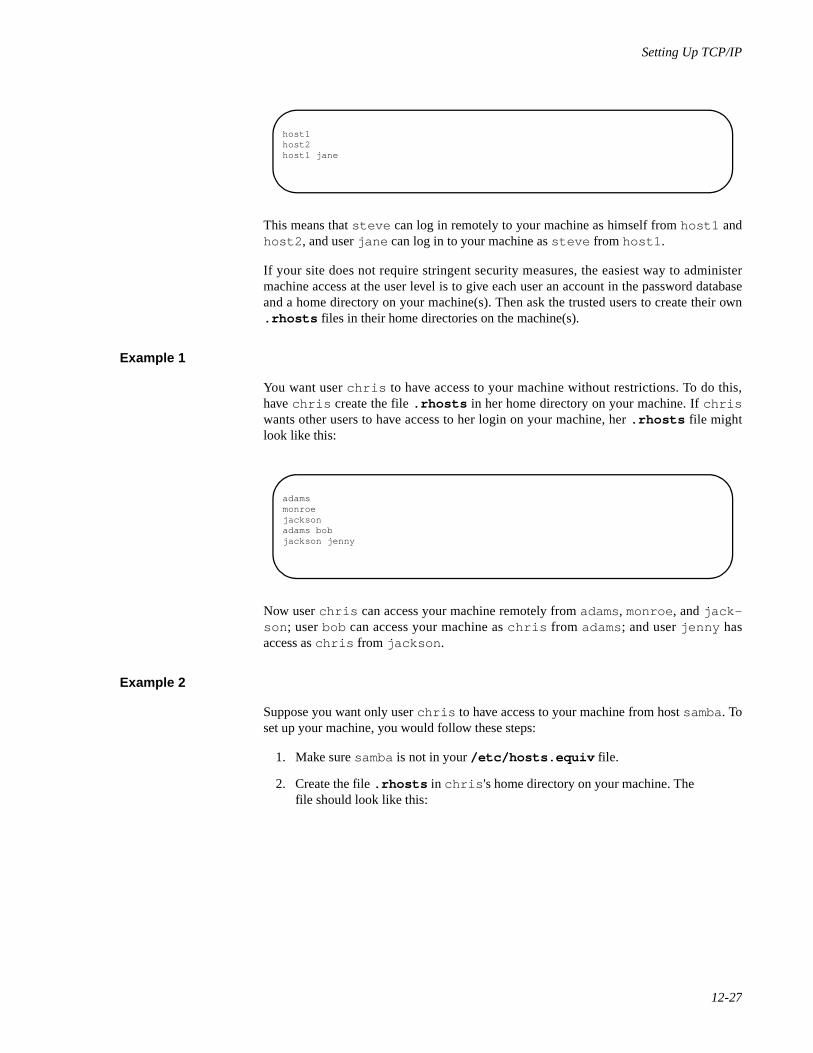
Setting Up TCP/IP
12-27
This means that steve can log in remotely to your machine as himself from host1 andhost2 , and user jane can log in to your machine as steve from host1 .
If your site does not require stringent security measures, the easiest way to administermachine access at the user level is to give each user an account in the password databaseand a home directory on your machine(s). Then ask the trusted users to create their own.rhosts files in their home directories on the machine(s).
Example 1 12
You want user chris to have access to your machine without restrictions. To do this,have chris create the file .rhosts in her home directory on your machine. If chriswants other users to have access to her login on your machine, her .rhosts file mightlook like this:
Now user chris can access your machine remotely from adams, monroe , and jack-son ; user bob can access your machine as chris from adams; and user jenny hasaccess as chris from jackson .
Example 2 12
Suppose you want only user chris to have access to your machine from host samba. Toset up your machine, you would follow these steps:
1. Make sure samba is not in your /etc/hosts.equiv file.
2. Create the file .rhosts in chris 's home directory on your machine. Thefile should look like this:
host1host2host1 jane
adamsmonroejacksonadams bobjackson jenny
Network Administration
12-28
Security Issues 12
The only way to achieve anything resembling security in a sensitive environment is toexclude users from your password database; once someone knows a password, he or shecan access your machine.
Some TCP/IP user services are especially problematic in an environment that requiresstrict security. For example, the finger command allows a user to display users on aremote host. The command starts the finger daemon (fingerd ) on the remotemachine, which then reports to the user the user name and full name of everyone who islogged in to the machine. There is no authentication of the requestor and no auditing of therequests. Similarly, the rwhod daemon (on whose information the ruptime commandbases its reports) freely passes around information about who is logged in to a machine.
There are no files or databases to restrict access to the information provided by thesedaemons; therefore, by default, they are not run. If you do not require strict security, youcan run fingerd by deleting the comment character from the line that starts fingerd inthe file /etc/inet/inetd.conf . To start rwhod , add the line:
to the end of the start-up script /etc/inet/rc.inet .
Disabling the TCP/IP Network Services 12
You may want to use an application over the network and disable the TCP/IP networkservice commands. System administrators can configure TCP/IP solely as a transportprovider and disable TCP/IP services including telnet , rsh , rlogin , and rcp .
This would allow other networking services (such as RPC and NFS) to continue to workover TCP/IP. Use the inet.priv shell script to disable or restore TCP/IP services asshown in the following syntax:
To disable TCP/IP services, type:
samba
/usr/sbin/in.rwhod
Setting Up TCP/IP
12-29
To enable TCP/IP services, type:
Once disabled, TCP/IP service commands will remain disabled even after system reboots.The enable option must be run in System Maintenance Mode with privilege. The shellscript must be started by the appropriate user ID with privilege.
TCP/IP Services and Enhanced Security Issues 12
Using TCP/IP network services with the Enhanced Security package produces a potentialsecurity risk by exposing systems to more points of entry. Although running MandatoryAccess Control (MAC) over your network will not affect the TCP/IP services, MAC itselfcannot restrict the access of users logging in to server machines with TCP/IP servicecommands. For more information on MAC, see the chapters in the “SecurityAdministration” part of the System Administration. guide. For securely authenticated net-work commands, see the chapter “Remote Services Tutorial” in the User's Guide.
The purpose of this section is to point out the effect of using TCP/IP services over net-works containing the Enhanced Security package, and to recommend steps for minimizingthe security risk.
Minimizing TCP/IP Security Risks 12
The TCP/IP daemons minimize potential access security risks by stripping processprivileges before invoking remote requests. Stripping process privileges occurs regardlessof the security level at which you logged in. Even if you are a system administrator loggedin at the SYS_PRIVATE (remote login) level, your remote login request (rlogin ortelnet ) will produce a shell without privileges.
TCP/IP and Secure Device Handling 12
The Enhanced Security package allocates devices for the TCP/IP daemons. The TCP/IPdevices are initialized to a private state and a user-accessible security level.
/sbin/sh /etc/inet/inet.priv -d
/sbin/sh /etc/inet/inet.priv -e
Network Administration
12-30
NOTE
Changing the default device allocation attributes may affect thefunctionality of TCP/IP services. We recommend that systemadministrators not change the device allocation. Any changes mayconflict with the ability of the TCP/IP services to use the securedevices.
SYS_PRIVATE and USER_LOGIN Security Levels 12
When used with the enhanced security package, TCP/IP network services react the sameas other network services by permitting you to log in without privileges, even if you log inas a privileged user such as root . A system administrator can log on to server machinesat the SYS_PRIVATE or USER_LOGIN security level. The level at which administratorslogin will dictate the TCP/IP services they can execute and the files on which thecommands will work. If you are a system administrator logged on to server machines atthe SYS_PRIVATE level, you can not use TCP/IP services to access files at theUSER_LOGIN level, even when performing administrative tasks. Conversely, logging onat the USER_LOGIN level will let you use certain TCP/IP services, but they will fail ifexecuted on SYS_PRIVATE level files.
Most of the TCP/IP administrative database files must be set for use at the SYS_PUBLIClevel. The exception is the user's $HOME/.rhosts file, which operates at theUSER_LOGIN level.
If you need to access multiple levels, we recommend that you use the network servicesprovided by the Basic Networking Utilities (BNU), REXEC, Remote File Sharing, or theConnection Server. For more information on remote access at several levels, seeChapter 1, "Introduction to Network Services Administration". The following sections listthe files contained in the SYS_PRIVATE and USER_LOGIN levels.
Setting Up the Network Administrator's Login 12
If you are running the Enhanced Security Utilities, which is provided as part of theEnhanced Security add-on package, the concept of the superuser has been replaced byadministrative roles. Each administrative role is associated with commands and privilegesrequired to administer a certain aspect of the system. To administer network services, youmust assume the role of the network administrator NET. The NET role is predefined on thesystem, but before you can log in as a network administrator, you must create a login andassign it the NET role. This is done using the adminuser command.
For information about assigning roles, see the chapter “Trusted Facility Management” inthe System Administration guide or adminuser(1M) .
SYS_PRIVATE Level Executables 12
The following executables depend on inheritable privileges and must be run at theSYS_PRIVATE security level from a privileged process. To gain privilege to run a com-mand, your user ID must be in the NET role. Use the adminuser(1M) command to addusers to the NET role. Use the tfadmin(1M) command to acquire privilege.
To remotely execute these binaries (with privilege), we recommend that you invoke themusing the Basic Networking Utilities (BNU) network services or the REXEC service,
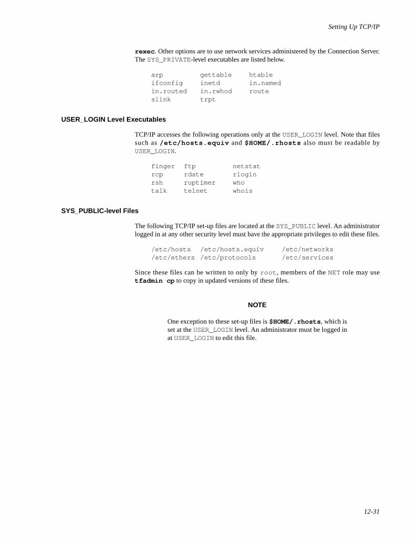
Setting Up TCP/IP
12-31
rexec . Other options are to use network services administered by the Connection Server.The SYS_PRIVATE-level executables are listed below.
arp gettable htableifconfig inetd in.namedin.routed in.rwhod routeslink trpt
USER_LOGIN Level Executables 12
TCP/IP accesses the following operations only at the USER_LOGIN level. Note that filessuch as /etc/hosts.equiv and $HOME/.rhosts also must be readable byUSER_LOGIN.
finger ftp netstatrcp rdate rloginrsh ruptimer whotalk telnet whois
SYS_PUBLIC-level Files 12
The following TCP/IP set-up files are located at the SYS_PUBLIC level. An administratorlogged in at any other security level must have the appropriate privileges to edit these files.
/etc/hosts /etc/hosts.equiv /etc/networks/etc/ethers /etc/protocols /etc/services
Since these files can be written to only by root , members of the NET role may usetfadmin cp to copy in updated versions of these files.
NOTE
One exception to these set-up files is $HOME/.rhosts , which isset at the USER_LOGIN level. An administrator must be logged inat USER_LOGIN to edit this file.

Network Administration
12-32
13Setting Up Routers and Subnetworks
Introduction to Router and Subnetwork Administration . . . . . . . . . . . . . . . . . . . . . . 13-1Configuring Routing . . . . . . . . . . . . . . . . . . . . . . . . . . . . . . . . . . . . . . . . . . . . . . . . . 13-1
Using the routed Daemon. . . . . . . . . . . . . . . . . . . . . . . . . . . . . . . . . . . . . . . . . . 13-2Preparing for Routing. . . . . . . . . . . . . . . . . . . . . . . . . . . . . . . . . . . . . . . . . . . . . 13-2Options for the Generic configure Command . . . . . . . . . . . . . . . . . . . . . . . . . . 13-5
Configuring Multiple Network Cards . . . . . . . . . . . . . . . . . . . . . . . . . . . . . 13-6Configuring the First Network Device. . . . . . . . . . . . . . . . . . . . . . . . . 13-6Configuring the Next Network Device . . . . . . . . . . . . . . . . . . . . . . . . 13-9Configuring the System as a Gateway . . . . . . . . . . . . . . . . . . . . . . . . . 13-11Sample Router Files . . . . . . . . . . . . . . . . . . . . . . . . . . . . . . . . . . . . . . . 13-11
Setting up the Route Daemon. . . . . . . . . . . . . . . . . . . . . . . . . . . . . . . . . . . . . . . 13-12Setting Up Router Clients. . . . . . . . . . . . . . . . . . . . . . . . . . . . . . . . . . . . . . . . . . 13-14
Specifying a Default Router . . . . . . . . . . . . . . . . . . . . . . . . . . . . . . . . . . . . 13-15Using Specific Routers . . . . . . . . . . . . . . . . . . . . . . . . . . . . . . . . . . . . . . . . 13-16Running the Route Daemon on a Client . . . . . . . . . . . . . . . . . . . . . . . . . . . 13-17
Setting Up Subnets . . . . . . . . . . . . . . . . . . . . . . . . . . . . . . . . . . . . . . . . . . . . . . . 13-17Network Masks . . . . . . . . . . . . . . . . . . . . . . . . . . . . . . . . . . . . . . . . . . . . . . 13-18Changing to a Subnetted Network . . . . . . . . . . . . . . . . . . . . . . . . . . . . . . . 13-19
Examples of Subnets . . . . . . . . . . . . . . . . . . . . . . . . . . . . . . . . . . . . . . 13-19

Network Administration
13-1
13Chapter 13Setting Up Routers and Subnetworks
131313
Introduction to Router and Subnetwork Administration 13
Routing and subnetworking are important features as your organization's networkingneeds grow. Subnetworking lets you divide up your pool of IP addresses so you can splitthose addresses across several physical networks within your organization. Routingprovides a means of passing information from one physical network to another. In thischapter, we describe how to set up a system to route packets from one network to another,as well as how to assign addressing and network masking to do subnetworking.
Configuring Routing 13
A TCP/IP network usually interconnects a number of hosts. Your host is connected to aTCP/IP network via a hardware network interface. Individual TCP/IP networks are in turninterconnected via IP routers. IP routers forward IP packets from one TCP/IP network toanother, and exchange routing information with each other to deliver packets across anumber of networks. Other types of routers may forward traffic for protocol families otherthan TCP/IP.
NOTE
We refer to the term “router” throughout this chapter. Thoughtechnically a router refers to a machine that does nothing butrouting, we are usually referring to a system that does routingamong its other activities. Therefore, we sometimes refer to thesystem as a gateway system.
If all of the hosts at your site are connected to a single TCP/IP network that is notinterconnected with any other TCP/IP networks, an IP router is unnecessary. If your sitecomprises many TCP/IP networks, or if you want to interconnect your network with otherTCP/IP networks, you must configure the interconnections with IP routers in order for allhosts to communicate.
Many types of machines may serve as IP routers. A number of vendors offer machinesdedicated entirely to the function of IP routing. A system may act both as a host (offeringnetwork services such as remote login) and a router.
Network Administration
13-2
Using the routed Daemon 13
The routed (routing daemon) program implements a standard routing protocol. If asystem has only one network interface, routed will passively monitor the routing traffic(if that network is a broadcast network). If a system has two or more network interfacesand is set up to be a gateway, the routed program will actively participate in theexchange of routing information with other routers.
For more information about routed , see routed(1M) and “Setting up the Route Dae-mon” on page 13-12.
Preparing for Routing 13
Before actually configuring your system to do routing, make the following preparations.
• Assign the router a unique host name and a unique IP address for each net-work it is on. The Internet Protocol architecture requires each interface tohave a unique IP address.
• Make sure you have acquired registered IP network numbers for each net-work the router is to connect. (This may require subnetworking within yourexisting network.)
• If you have not installed the TCP/IP Internet package, install it followingthe instructions in the Release Notes.
Once you have TCP/IP installed, do the following from a Terminal window as the rootuser:
1. Access /etc/networks and add the network names and networknumbers of all the networks that the router can reach.
2. If you have more than one network card (device) installed in your machine,you must run /etc/confnet.d/configure -i [see genericconfigure(1M)]. (/etc/confnet.d/configure will be referredto as configure in the following explanation).
When you run configure -i , you are interactively configuring thedevice(s) in your machine. You can run the configure script once foreach device that is installed, or you can specify the number(s) of thedevice(s), separated by white space, when you are asked which devices(s)you want to configure/reconfigure. Before you run configure, your networkcards should already be installed and set up.
The configure script runs a protocol-specific configure script (forexample, inet , [see INET-specific configure(1M)] . The protocol-specific configure scripts are not meant to be run by a user.
An entry in /etc/hosts should be added for each network card that isinstalled in your machine before you run configure -i . If an entry doesnot exist for a network card in /etc/hosts , you will be prompted toenter a valid name and IP address for the device that is being configured.
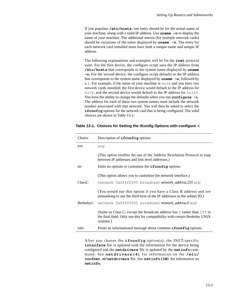
Setting Up Routers and Subnetworks
13-3
If you populate /etc/hosts , one entry should be for the actual name ofyour machine, along with a valid IP address. Use uname -n to display thename of your machine. The additional entries (for multiple network cards)should be variations of the name displayed by uname -n . The entry foreach network card installed must have both a unique name and unique IPaddress.
The following explanations and examples will be for the inet protocolsuite. For the first device, the configure script uses the IP address from/etc/hosts that corresponds to the system name displayed by uname-n . For the second device, the configure script defaults to the IP addressthat corresponds to the system name displayed by uname -n , followed bya 2. For example, if the name of your machine is hulk and you have twonetwork cards installed, the first device would default to the IP address forhulk , and the second device would default to the IP address for hulk2 .You have the ability to change the defaults when you run configure -i .The address for each of these two system names must include the networknumber associated with that network. You will then be asked to select theifconfig options for the network card that is being configured. The validchoices are shown in Table 13-1:
After you choose the i fconfig option(s) , the INET-specificinterface file is updated with the information for the device beingconfigured and the netdrivers file is updated by the netinfo com-mand. See netdr ivers(4) for in format ion on the /etc/confnet.d/netdrivers file. See netinfo(1M) for information onnetinfo .
Table 13-1. Choices for Setting the ifconfig Options with configure -i
Choice Description of ifconfig options
yes arp
(This option enables the use of the Address Resolution Protocol to mapbetween IP addresses and link level addresses.)
no Enter no options or customize the ifconfig options.
(This option allows you to customize the network interface.)
ClassC netmask 0xffffff00 broadcast network_address.255 arp
(You would use this option if you have a Class B address and arenetmasking to use the third byte of the IP addresses as the subnet ID.)
BerkeleyC netmask 0xffffff00 broadcast network_address.0 arp
(Same as Class C, except the broadcast address has 0 rather than 255 inthe final field. Only use this for compatibility with certain Berkeley UNIXsystems.)
info Prints an informational message about common ifconfig options.
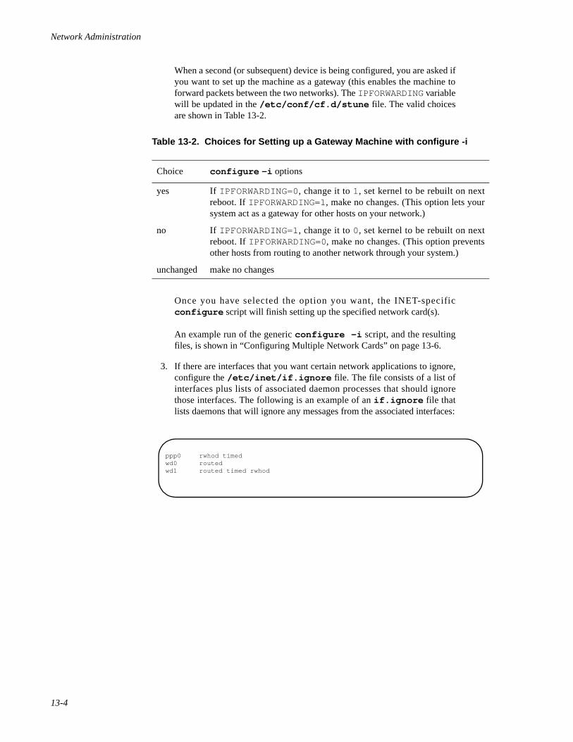
Network Administration
13-4
When a second (or subsequent) device is being configured, you are asked ifyou want to set up the machine as a gateway (this enables the machine toforward packets between the two networks). The IPFORWARDING variablewill be updated in the /etc/conf/cf.d/stune file. The valid choicesare shown in Table 13-2.
Once you have selected the option you want, the INET-specificconfigure script will finish setting up the specified network card(s).
An example run of the generic configure -i script, and the resultingfiles, is shown in “Configuring Multiple Network Cards” on page 13-6.
3. If there are interfaces that you want certain network applications to ignore,configure the /etc/inet/if.ignore file. The file consists of a list ofinterfaces plus lists of associated daemon processes that should ignorethose interfaces. The following is an example of an if.ignore file thatlists daemons that will ignore any messages from the associated interfaces:
Table 13-2. Choices for Setting up a Gateway Machine with configure -i
Choice configure -i options
yes If IPFORWARDING=0, change it to 1, set kernel to be rebuilt on nextreboot. If IPFORWARDING=1, make no changes. (This option lets yoursystem act as a gateway for other hosts on your network.)
no If IPFORWARDING=1, change it to 0, set kernel to be rebuilt on nextreboot. If IPFORWARDING=0, make no changes. (This option preventsother hosts from routing to another network through your system.)
unchanged make no changes
ppp0 rwhod timedwd0 routedwd1 routed timed rwhod
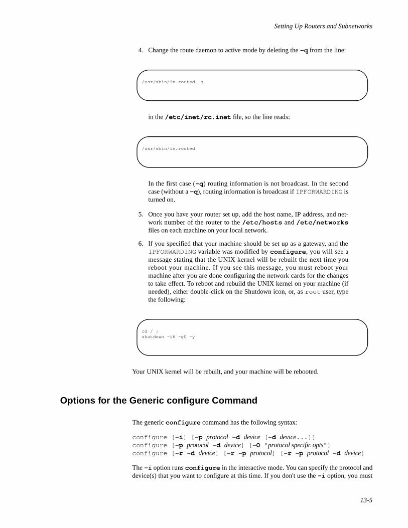
Setting Up Routers and Subnetworks
13-5
4. Change the route daemon to active mode by deleting the -q from the line:
in the /etc/inet/rc.inet file, so the line reads:
In the first case (-q ) routing information is not broadcast. In the secondcase (without a -q ), routing information is broadcast if IPFORWARDING isturned on.
5. Once you have your router set up, add the host name, IP address, and net-work number of the router to the /etc/hosts and /etc/networksfiles on each machine on your local network.
6. If you specified that your machine should be set up as a gateway, and theIPFORWARDING variable was modified by configure , you will see amessage stating that the UNIX kernel will be rebuilt the next time youreboot your machine. If you see this message, you must reboot yourmachine after you are done configuring the network cards for the changesto take effect. To reboot and rebuild the UNIX kernel on your machine (ifneeded), either double-click on the Shutdown icon, or, as root user, typethe following:
Your UNIX kernel will be rebuilt, and your machine will be rebooted.
Options for the Generic configure Command 13
The generic configure command has the following syntax:
configure [ -i ] [ -p protocol -d device [ -d device...]]configure [ -p protocol -d device] [ -O " protocol specific opts"]configure [ -r -d device] [ -r -p protocol] [ -r -p protocol -d device]
The -i option runs configure in the interactive mode. You can specify the protocol anddevice(s) that you want to configure at this time. If you don't use the -i option, you must
/usr/sbin/in.routed -q
/usr/sbin/in.routed
cd / ;shutdown -i6 -g0 -y
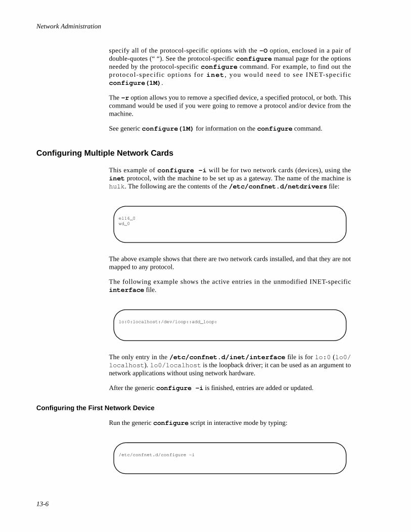
Network Administration
13-6
specify all of the protocol-specific options with the -O option, enclosed in a pair ofdouble-quotes (“ “). See the protocol-specific configure manual page for the optionsneeded by the protocol-specific configure command. For example, to find out theprotocol-specific options for inet , you would need to see INET-specificconfigure(1M) .
The -r option allows you to remove a specified device, a specified protocol, or both. Thiscommand would be used if you were going to remove a protocol and/or device from themachine.
See generic configure(1M) for information on the configure command.
Configuring Multiple Network Cards 13
This example of configure -i will be for two network cards (devices), using theinet protocol, with the machine to be set up as a gateway. The name of the machine ishulk . The following are the contents of the /etc/confnet.d/netdrivers file:
The above example shows that there are two network cards installed, and that they are notmapped to any protocol.
The following example shows the active entries in the unmodified INET-specificinterface file.
The only entry in the /etc/confnet.d/inet/interface file is for lo:0 (lo0/localhost ). lo0/localhost is the loopback driver; it can be used as an argument tonetwork applications without using network hardware.
After the generic configure -i is finished, entries are added or updated.
Configuring the First Network Device 13
Run the generic configure script in interactive mode by typing:
el16_0wd_0
lo:0:localhost:/dev/loop::add_loop:
/etc/confnet.d/configure -i
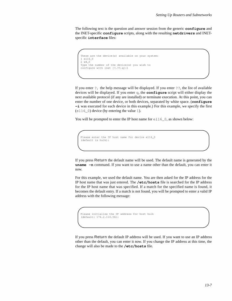
Setting Up Routers and Subnetworks
13-7
The following text is the question and answer session from the generic configure andthe INET-specific configure scripts, along with the resulting netdrivers and INET-specific interface files:
If you enter ?, the help message will be displayed. If you enter ??, the list of availabledevices will be displayed. If you enter q, the configure script will either display thenext available protocol (if any are installed) or terminate execution. At this point, you canenter the number of one device, or both devices, separated by white space. (configure-i was executed for each device in this example.) For this example, we specify the first(el16_0 ) device (by entering the value 1).
You will be prompted to enter the IP host name for el16_0 , as shown below:
If you press Return the default name will be used. The default name is generated by theuname -n command. If you want to use a name other than the default, you can enter itnow.
For this example, we used the default name. You are then asked for the IP address for theIP host name that was just entered. The /etc/hosts file is searched for the IP addressfor the IP host name that was specified. If a match for the specified name is found, itbecomes the default entry. If a match is not found, you will be prompted to enter a valid IPaddress with the following message:
If you press Return the default IP address will be used. If you want to use an IP addressother than the default, you can enter it now. If you change the IP address at this time, thechange will also be made to the /etc/hosts file.
These are the device(s) available on your system:1 el16_02 wd_0Type the number of the device(s) you wish toconfigure with inet [?,??,q]:1
Please enter the IP host name for device el16_0(default is hulk):
Please initialize the IP address for host hulk(default: 174.2.110.56):
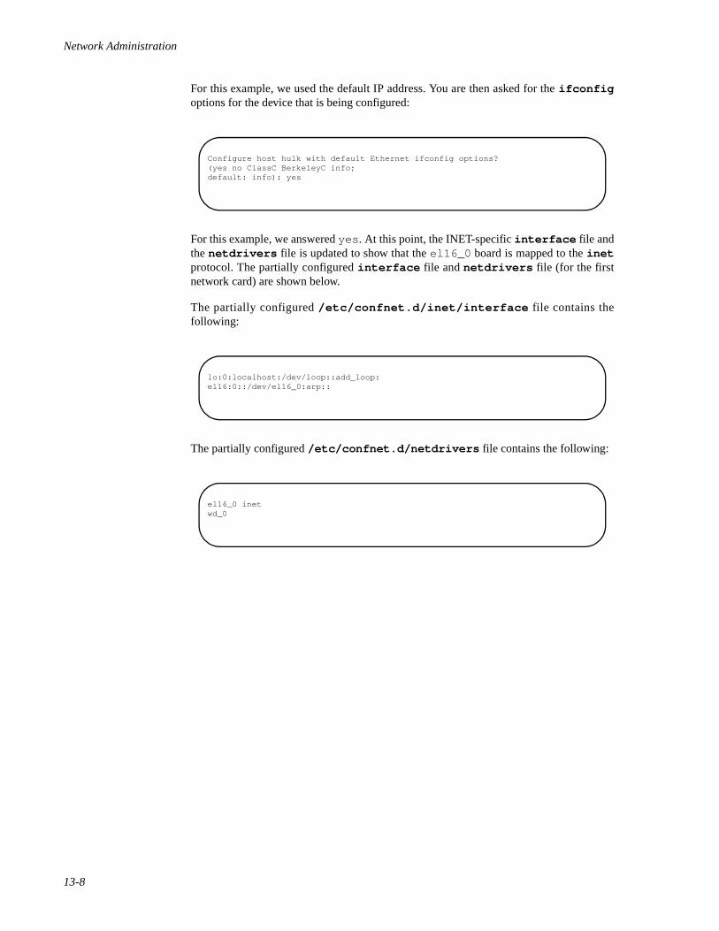
Network Administration
13-8
For this example, we used the default IP address. You are then asked for the ifconfigoptions for the device that is being configured:
For this example, we answered yes . At this point, the INET-specific interface file andthe netdrivers file is updated to show that the el16_0 board is mapped to the inetprotocol. The partially configured interface file and netdrivers file (for the firstnetwork card) are shown below.
The partially configured /etc/confnet.d/inet/interface file contains thefollowing:
The partially configured /etc/confnet.d/netdrivers file contains the following:
Configure host hulk with default Ethernet ifconfig options?(yes no ClassC BerkeleyC info;default: info): yes
lo:0:localhost:/dev/loop::add_loop:el16:0::/dev/el16_0:arp::
el16_0 inetwd_0
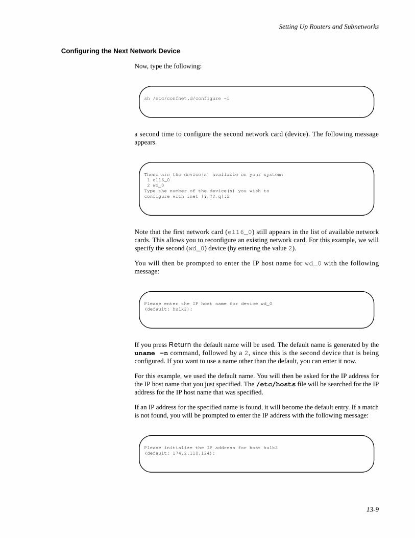
Setting Up Routers and Subnetworks
13-9
Configuring the Next Network Device 13
Now, type the following:
a second time to configure the second network card (device). The following messageappears.
Note that the first network card (el16_0 ) still appears in the list of available networkcards. This allows you to reconfigure an existing network card. For this example, we willspecify the second (wd_0) device (by entering the value 2).
You will then be prompted to enter the IP host name for wd_0 with the followingmessage:
If you press Return the default name will be used. The default name is generated by theuname -n command, followed by a 2, since this is the second device that is beingconfigured. If you want to use a name other than the default, you can enter it now.
For this example, we used the default name. You will then be asked for the IP address forthe IP host name that you just specified. The /etc/hosts file will be searched for the IPaddress for the IP host name that was specified.
If an IP address for the specified name is found, it will become the default entry. If a matchis not found, you will be prompted to enter the IP address with the following message:
sh /etc/confnet.d/configure -i
These are the device(s) available on your system: 1 el16_0 2 wd_0Type the number of the device(s) you wish toconfigure with inet [?,??,q]:2
Please enter the IP host name for device wd_0(default: hulk2):
Please initialize the IP address for host hulk2(default: 174.2.110.124):
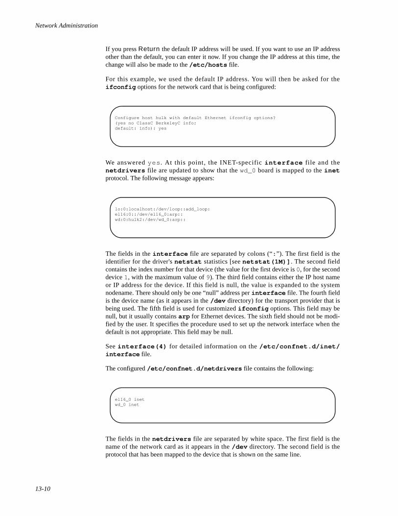
Network Administration
13-10
If you press Return the default IP address will be used. If you want to use an IP addressother than the default, you can enter it now. If you change the IP address at this time, thechange will also be made to the /etc/hosts file.
For this example, we used the default IP address. You will then be asked for theifconfig options for the network card that is being configured:
We answered yes . At this point, the INET-specific interface fi le and thenetdrivers file are updated to show that the wd_0 board is mapped to the inetprotocol. The following message appears:
The fields in the interface file are separated by colons (“: ”). The first field is theidentifier for the driver's netstat statistics [see netstat(1M)] . The second fieldcontains the index number for that device (the value for the first device is 0, for the seconddevice 1, with the maximum value of 9). The third field contains either the IP host nameor IP address for the device. If this field is null, the value is expanded to the systemnodename. There should only be one “null” address per interface file. The fourth fieldis the device name (as it appears in the /dev directory) for the transport provider that isbeing used. The fifth field is used for customized ifconfig options. This field may benull, but it usually contains arp for Ethernet devices. The sixth field should not be modi-fied by the user. It specifies the procedure used to set up the network interface when thedefault is not appropriate. This field may be null.
See interface(4) for detailed information on the /etc/confnet.d/inet/interface file.
The configured /etc/confnet.d/netdrivers file contains the following:
The fields in the netdrivers file are separated by white space. The first field is thename of the network card as it appears in the /dev directory. The second field is theprotocol that has been mapped to the device that is shown on the same line.
Configure host hulk with default Ethernet ifconfig options?(yes no ClassC BerkeleyC info;default: info): yes
lo:0:localhost:/dev/loop::add_loop:el16:0::/dev/el16_0:arp::wd:0:hulk2:/dev/wd_0:arp::
el16_0 inetwd_0 inet
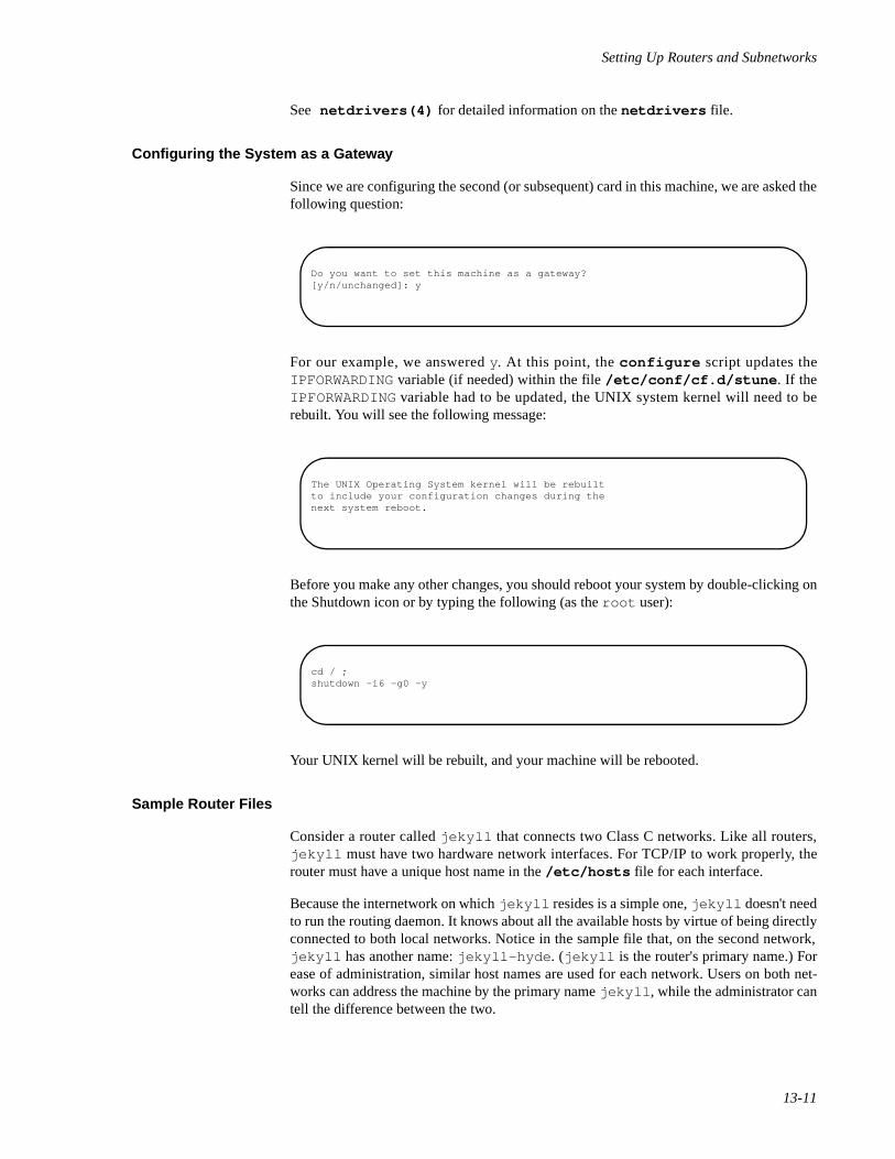
Setting Up Routers and Subnetworks
13-11
See netdrivers(4) for detailed information on the netdrivers file.
Configuring the System as a Gateway 13
Since we are configuring the second (or subsequent) card in this machine, we are asked thefollowing question:
For our example, we answered y. At this point, the configure script updates theIPFORWARDING variable (if needed) within the file /etc/conf/cf.d/stune . If theIPFORWARDING variable had to be updated, the UNIX system kernel will need to berebuilt. You will see the following message:
Before you make any other changes, you should reboot your system by double-clicking onthe Shutdown icon or by typing the following (as the root user):
Your UNIX kernel will be rebuilt, and your machine will be rebooted.
Sample Router Files 13
Consider a router called jekyll that connects two Class C networks. Like all routers,jekyll must have two hardware network interfaces. For TCP/IP to work properly, therouter must have a unique host name in the /etc/hosts file for each interface.
Because the internetwork on which jekyll resides is a simple one, jekyll doesn't needto run the routing daemon. It knows about all the available hosts by virtue of being directlyconnected to both local networks. Notice in the sample file that, on the second network,jekyll has another name: jekyll-hyde . (jekyll is the router's primary name.) Forease of administration, similar host names are used for each network. Users on both net-works can address the machine by the primary name jekyll , while the administrator cantell the difference between the two.
Do you want to set this machine as a gateway?[y/n/unchanged]: y
The UNIX Operating System kernel will be rebuiltto include your configuration changes during thenext system reboot.
cd / ;shutdown -i6 -g0 -y
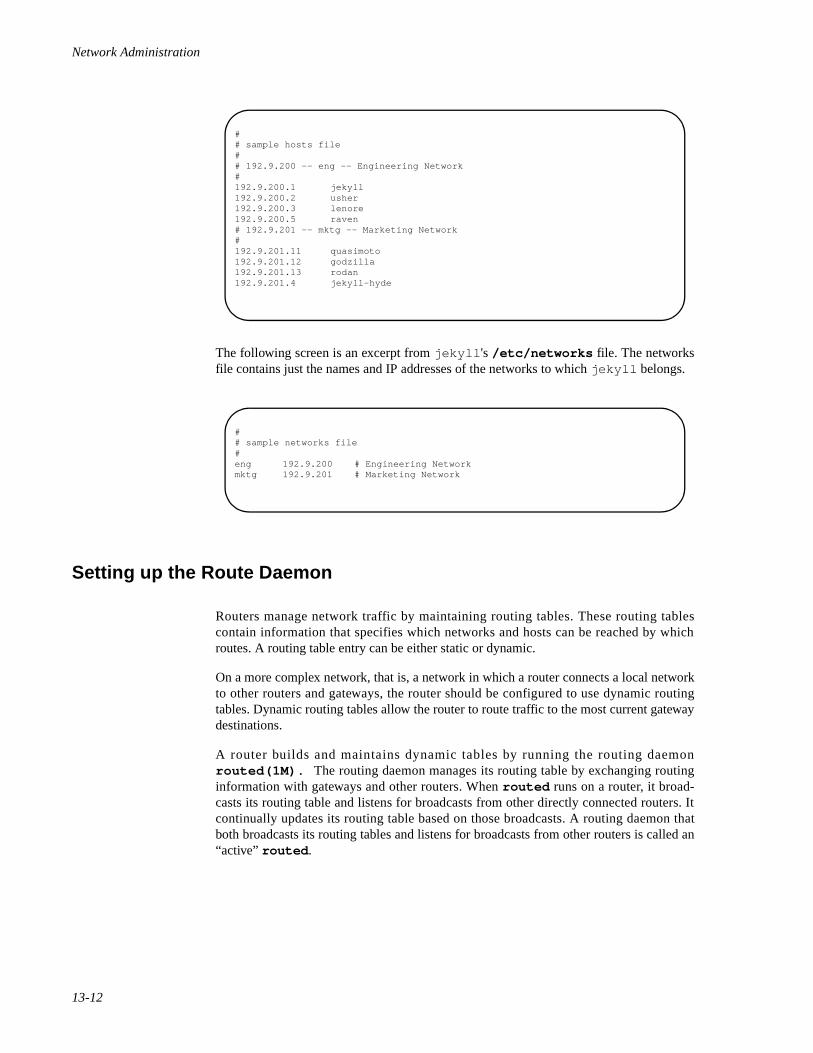
Network Administration
13-12
The following screen is an excerpt from jekyll 's /etc/networks file. The networksfile contains just the names and IP addresses of the networks to which jekyll belongs.
Setting up the Route Daemon 13
Routers manage network traffic by maintaining routing tables. These routing tablescontain information that specifies which networks and hosts can be reached by whichroutes. A routing table entry can be either static or dynamic.
On a more complex network, that is, a network in which a router connects a local networkto other routers and gateways, the router should be configured to use dynamic routingtables. Dynamic routing tables allow the router to route traffic to the most current gatewaydestinations.
A router builds and maintains dynamic tables by running the routing daemonrouted(1M). The routing daemon manages its routing table by exchanging routinginformation with gateways and other routers. When routed runs on a router, it broad-casts its routing table and listens for broadcasts from other directly connected routers. Itcontinually updates its routing table based on those broadcasts. A routing daemon thatboth broadcasts its routing tables and listens for broadcasts from other routers is called an“active” routed .
## sample hosts file## 192.9.200 -- eng -- Engineering Network #192.9.200.1 jekyll192.9.200.2 usher192.9.200.3 lenore192.9.200.5 raven # 192.9.201 -- mktg -- Marketing Network # 192.9.201.11 quasimoto192.9.201.12 godzilla192.9.201.13 rodan 192.9.201.4 jekyll-hyde
## sample networks file#eng 192.9.200 # Engineering Networkmktg 192.9.201 # Marketing Network
Setting Up Routers and Subnetworks
13-13
NOTE
routed can also run on a client. However, when it runs on aclient, routed simply listens for broadcasts and updates its localrouting table; it does not broadcast to other machines. This iscalled a “passive” routed . For information about runningrouted on a client, see routed(1M) and “Setting Up RouterClients” on page 13-14.
When routed is first initialized on a router, it builds its table using the contents of the file/etc/gateways (if it exists), which contains the address and distance to various net-works and gateways. Once it starts to run, routed immediately begins to update its tablebased on broadcasts from other routers and gateways.
You need to create /etc/gateways if you want to tell other networks about a routerthat doesn't broadcast information to you. You can use any text editor to create /etc/gateways . The /etc/gateways file consists of a series of lines, each in the followingformat:
[net | host] hostname1 gateway hostname2 value [passive | active]
where the operands have the following meanings:
net | host This keyword indicates whether the route is to a networkor to a specific host, respectively.
hostname1 Specifies the name of the destination network or host. Thismay be a net name or host name, as specified in/etc/networks or /etc/hosts , or an IP address.
hostname2 Specifies the name or address of the gateway to whichmessages should be forwarded.
value This is a number indicating the number of “hops” to thedestination host or network.
passive | active This keyword indicates whether the gateway should betreated as passive or active gateway, respectively.
To run routed on a router automatically whenever TCP/IP is initialized, do thefollowing:
1. Set up the /etc/gateways file, if necessary. The changes will becomeactive when you reboot your system.
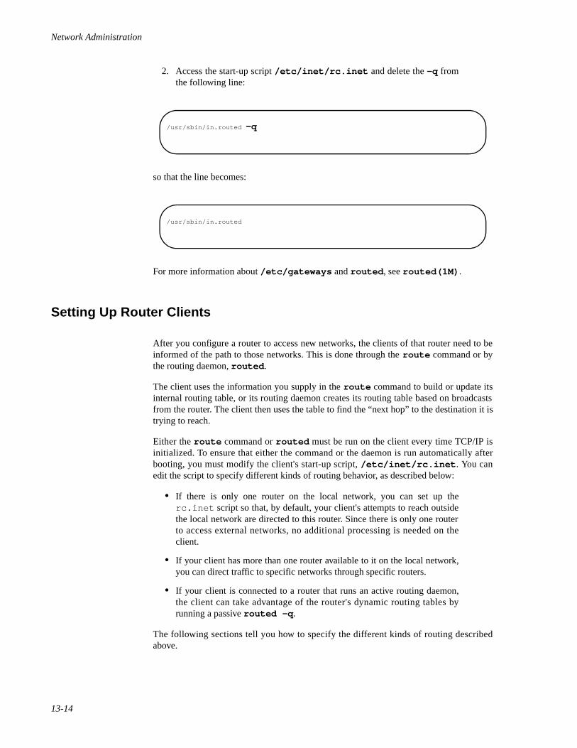
Network Administration
13-14
2. Access the start-up script /etc/inet/rc.inet and delete the -q fromthe following line:
so that the line becomes:
For more information about /etc/gateways and routed , see routed(1M) .
Setting Up Router Clients 13
After you configure a router to access new networks, the clients of that router need to beinformed of the path to those networks. This is done through the route command or bythe routing daemon, routed .
The client uses the information you supply in the route command to build or update itsinternal routing table, or its routing daemon creates its routing table based on broadcastsfrom the router. The client then uses the table to find the “next hop” to the destination it istrying to reach.
Either the route command or routed must be run on the client every time TCP/IP isinitialized. To ensure that either the command or the daemon is run automatically afterbooting, you must modify the client's start-up script, /etc/inet/rc.inet . You canedit the script to specify different kinds of routing behavior, as described below:
• If there is only one router on the local network, you can set up therc.inet script so that, by default, your client's attempts to reach outsidethe local network are directed to this router. Since there is only one routerto access external networks, no additional processing is needed on theclient.
• If your client has more than one router available to it on the local network,you can direct traffic to specific networks through specific routers.
• If your client is connected to a router that runs an active routing daemon,the client can take advantage of the router's dynamic routing tables byrunning a passive routed -q .
The following sections tell you how to specify the different kinds of routing describedabove.
/usr/sbin/in.routed -q
/usr/sbin/in.routed
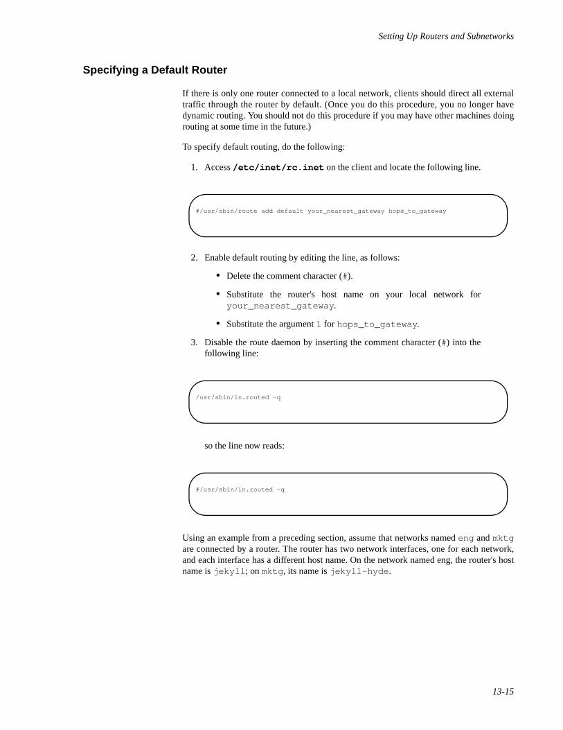
Setting Up Routers and Subnetworks
13-15
Specifying a Default Router 13
If there is only one router connected to a local network, clients should direct all externaltraffic through the router by default. (Once you do this procedure, you no longer havedynamic routing. You should not do this procedure if you may have other machines doingrouting at some time in the future.)
To specify default routing, do the following:
1. Access /etc/inet/rc.inet on the client and locate the following line.
2. Enable default routing by editing the line, as follows:
• Delete the comment character (#).
• Substitute the router's host name on your local network foryour_nearest_gateway .
• Substitute the argument 1 for hops_to_gateway .
3. Disable the route daemon by inserting the comment character (#) into thefollowing line:
so the line now reads:
Using an example from a preceding section, assume that networks named eng and mktgare connected by a router. The router has two network interfaces, one for each network,and each interface has a different host name. On the network named eng, the router's hostname is jekyll ; on mktg , its name is jekyll-hyde .
#/usr/sbin/route add default your_nearest_gateway hops_to_gateway
/usr/sbin/in.routed -q
#/usr/sbin/in.routed -q
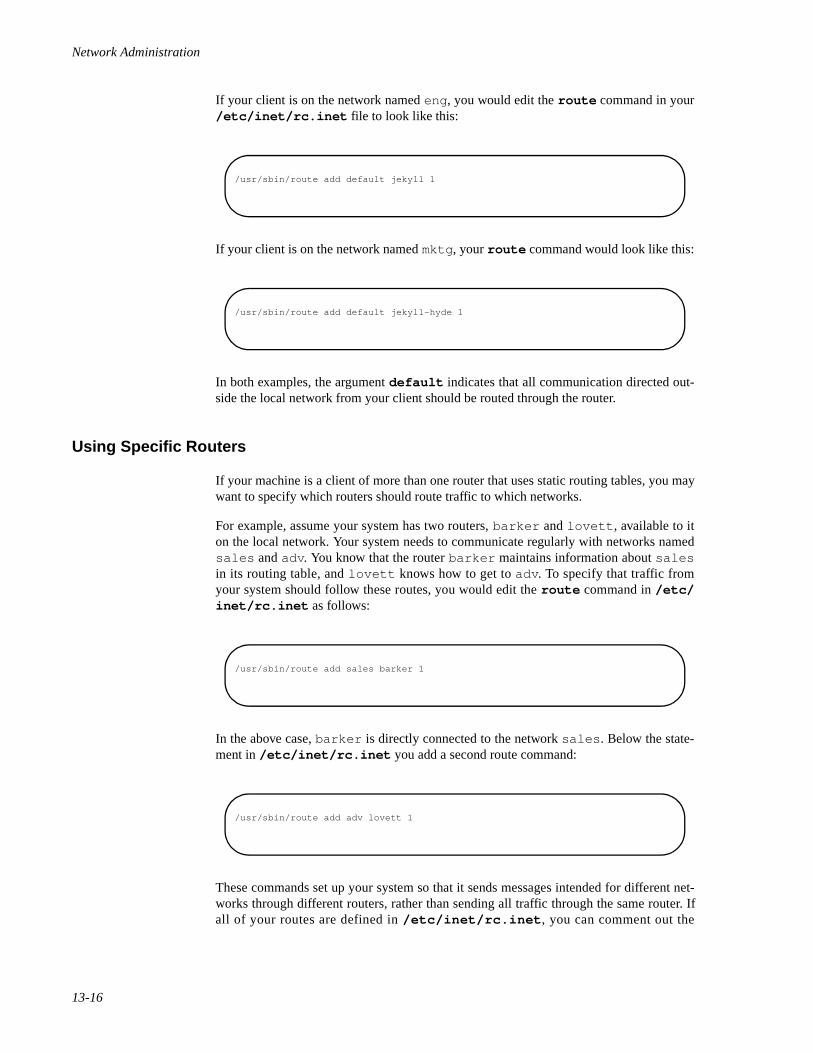
Network Administration
13-16
If your client is on the network named eng , you would edit the route command in your/etc/inet/rc.inet file to look like this:
If your client is on the network named mktg , your route command would look like this:
In both examples, the argument default indicates that all communication directed out-side the local network from your client should be routed through the router.
Using Specific Routers 13
If your machine is a client of more than one router that uses static routing tables, you maywant to specify which routers should route traffic to which networks.
For example, assume your system has two routers, barker and lovett , available to iton the local network. Your system needs to communicate regularly with networks namedsales and adv . You know that the router barker maintains information about salesin its routing table, and lovett knows how to get to adv . To specify that traffic fromyour system should follow these routes, you would edit the route command in /etc/inet/rc.inet as follows:
In the above case, barker is directly connected to the network sales . Below the state-ment in /etc/inet/rc.inet you add a second route command:
These commands set up your system so that it sends messages intended for different net-works through different routers, rather than sending all traffic through the same router. Ifall of your routes are defined in /etc/inet/rc.inet , you can comment out the
/usr/sbin/route add default jekyll 1
/usr/sbin/route add default jekyll-hyde 1
/usr/sbin/route add sales barker 1
/usr/sbin/route add adv lovett 1
Setting Up Routers and Subnetworks
13-17
/usr/sbin/in.routed -q line in the /etc/inet/rc.inet file to improve systemperformance.
A powerful way to set up routing for more complex networks is to provide several specific“ route add ” commands for frequently used networks, as well as a “route adddefault ” command to handle traffic to all other networks. This is particularly usefulwhen routers, in turn, use other routers.
For more information, see the route(1M) manual page.
Running the Route Daemon on a Client 13
If your machine is a client to a router that maintains a dynamic routing table, you can setup your client to update its own tables based on the router's broadcasts.
If the router is running the routed daemon, routed listens for broadcasts from otherrouters and gateways and continually updates its routing tables based on the information inthose broadcasts. It also broadcasts its own routing tables so that other machines can usethem for updating their own routing tables. Because routed on a router both broadcastsits own routing table and listens for broadcasts from other routers, it is known as an“active” routed . When routed -q is run on a client (that is, on a machine with onlyone network interface), it listens on the network and waits for the local router to broadcastits routing table. It then uses the broadcast information to update its own table. Becauserouted -q on a client does not broadcast its routing table, it is called a “passive” or“quiet” routed .
NOTE
Even if the local router uses dynamic routing tables, you canchoose not to run routed on the client. In this case, the client'stables remain static, even though the router's tables are dynamic.You might choose not to run routed on the client if the client ison a simple internetwork, and the routes to its usual destinationsdo not change.
If the client's router uses static routing tables (that is, it does notrun routed ), do not run routed on the client.
Setting Up Subnets 13
Using subnets is a way to divide the addresses for a single network to accommodate thefact that the network consists of several physical networks. For administrative or technicalreasons, many organizations choose to divide one network into several subnets.
Routing can get very complicated as the number of networks grows. For example, a smallorganization might give each local network a Class C number. As the organization grows,administering network numbers may get out of hand. A better idea is to allocate a Class Bnetwork for the entire company. Then, divide the Class B network into physical networks
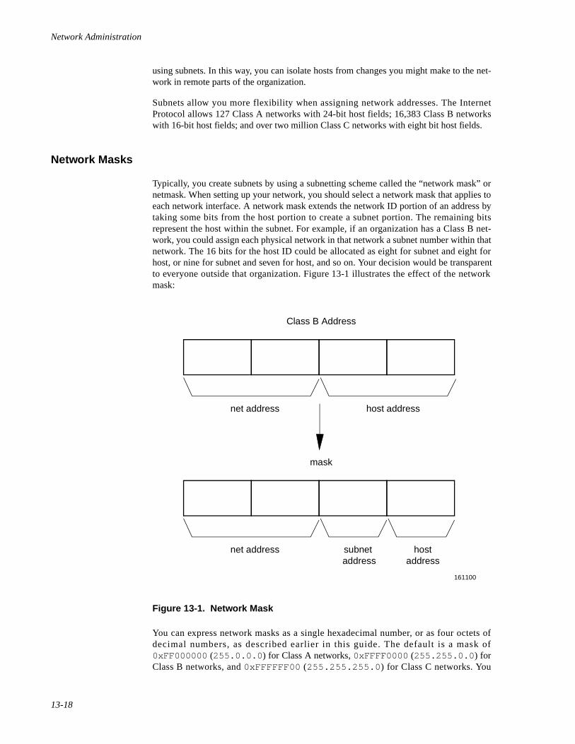
Network Administration
13-18
using subnets. In this way, you can isolate hosts from changes you might make to the net-work in remote parts of the organization.
Subnets allow you more flexibility when assigning network addresses. The InternetProtocol allows 127 Class A networks with 24-bit host fields; 16,383 Class B networkswith 16-bit host fields; and over two million Class C networks with eight bit host fields.
Network Masks 13
Typically, you create subnets by using a subnetting scheme called the “network mask” ornetmask. When setting up your network, you should select a network mask that applies toeach network interface. A network mask extends the network ID portion of an address bytaking some bits from the host portion to create a subnet portion. The remaining bitsrepresent the host within the subnet. For example, if an organization has a Class B net-work, you could assign each physical network in that network a subnet number within thatnetwork. The 16 bits for the host ID could be allocated as eight for subnet and eight forhost, or nine for subnet and seven for host, and so on. Your decision would be transparentto everyone outside that organization. Figure 13-1 illustrates the effect of the networkmask:
Figure 13-1. Network Mask
You can express network masks as a single hexadecimal number, or as four octets ofdecimal numbers, as described earlier in this guide. The default is a mask of0xFF000000 (255.0.0.0 ) for Class A networks, 0xFFFF0000 (255.255.0.0 ) forClass B networks, and 0xFFFFFF00 (255.255.255.0 ) for Class C networks. You
161100
Class B Address
net address
net address
host address
hostaddress
subnet address
mask
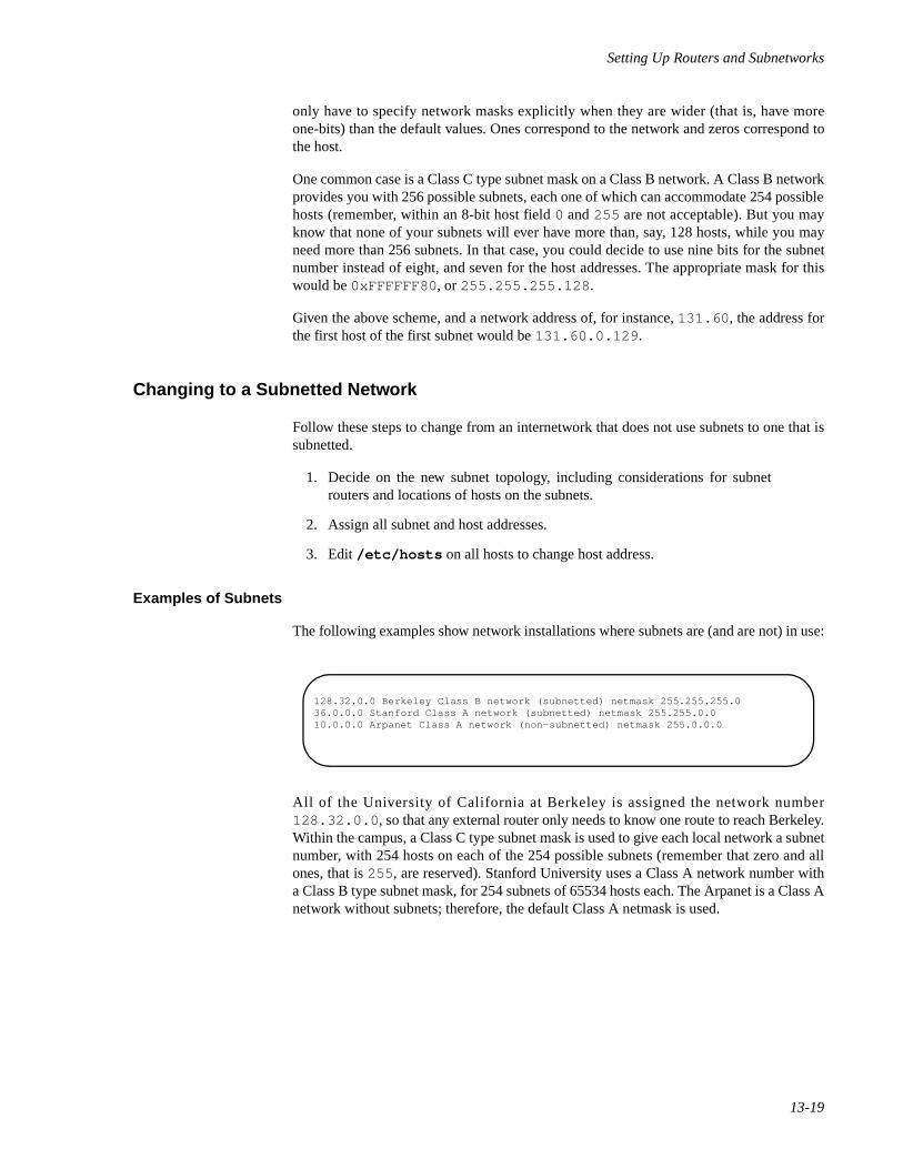
Setting Up Routers and Subnetworks
13-19
only have to specify network masks explicitly when they are wider (that is, have moreone-bits) than the default values. Ones correspond to the network and zeros correspond tothe host.
One common case is a Class C type subnet mask on a Class B network. A Class B networkprovides you with 256 possible subnets, each one of which can accommodate 254 possiblehosts (remember, within an 8-bit host field 0 and 255 are not acceptable). But you mayknow that none of your subnets will ever have more than, say, 128 hosts, while you mayneed more than 256 subnets. In that case, you could decide to use nine bits for the subnetnumber instead of eight, and seven for the host addresses. The appropriate mask for thiswould be 0xFFFFFF80 , or 255.255.255.128 .
Given the above scheme, and a network address of, for instance, 131.60 , the address forthe first host of the first subnet would be 131.60.0.129 .
Changing to a Subnetted Network 13
Follow these steps to change from an internetwork that does not use subnets to one that issubnetted.
1. Decide on the new subnet topology, including considerations for subnetrouters and locations of hosts on the subnets.
2. Assign all subnet and host addresses.
3. Edit /etc/hosts on all hosts to change host address.
Examples of Subnets 13
The following examples show network installations where subnets are (and are not) in use:
All of the University of California at Berkeley is assigned the network number128.32.0.0 , so that any external router only needs to know one route to reach Berkeley.Within the campus, a Class C type subnet mask is used to give each local network a subnetnumber, with 254 hosts on each of the 254 possible subnets (remember that zero and allones, that is 255 , are reserved). Stanford University uses a Class A network number witha Class B type subnet mask, for 254 subnets of 65534 hosts each. The Arpanet is a Class Anetwork without subnets; therefore, the default Class A netmask is used.
128.32.0.0 Berkeley Class B network (subnetted) netmask 255.255.255.036.0.0.0 Stanford Class A network (subnetted) netmask 255.255.0.010.0.0.0 Arpanet Class A network (non-subnetted) netmask 255.0.0.0

Network Administration
13-20
14Managing TCP/IP Nodes Using SNMP
Introduction to SNMP Administration . . . . . . . . . . . . . . . . . . . . . . . . . . . . . . . . . . . 14-1SNMP History . . . . . . . . . . . . . . . . . . . . . . . . . . . . . . . . . . . . . . . . . . . . . . . . . . . . . . 14-1Basic SNMP Concepts. . . . . . . . . . . . . . . . . . . . . . . . . . . . . . . . . . . . . . . . . . . . . . . . 14-2
SNMP Protocol. . . . . . . . . . . . . . . . . . . . . . . . . . . . . . . . . . . . . . . . . . . . . . . . . . 14-2Structure of Management Information (SMI) . . . . . . . . . . . . . . . . . . . . . . . . . . 14-2Management Information Base (MIB) . . . . . . . . . . . . . . . . . . . . . . . . . . . . . . . . 14-3Agents and Management Stations . . . . . . . . . . . . . . . . . . . . . . . . . . . . . . . . . . . 14-4Traps . . . . . . . . . . . . . . . . . . . . . . . . . . . . . . . . . . . . . . . . . . . . . . . . . . . . . . . . . . 14-4Authentication . . . . . . . . . . . . . . . . . . . . . . . . . . . . . . . . . . . . . . . . . . . . . . . . . . 14-4
Overview of SNMP . . . . . . . . . . . . . . . . . . . . . . . . . . . . . . . . . . . . . . . . . . . . . . . . . . 14-5Configuring the SNMP Agent . . . . . . . . . . . . . . . . . . . . . . . . . . . . . . . . . . . . . . . . . . 14-6Using the SNMP Commands. . . . . . . . . . . . . . . . . . . . . . . . . . . . . . . . . . . . . . . . . . . 14-7
getone Command . . . . . . . . . . . . . . . . . . . . . . . . . . . . . . . . . . . . . . . . . . . . . . . . 14-8getid Command . . . . . . . . . . . . . . . . . . . . . . . . . . . . . . . . . . . . . . . . . . . . . . . . . 14-8getmany Command. . . . . . . . . . . . . . . . . . . . . . . . . . . . . . . . . . . . . . . . . . . . . . . 14-9snmpstat Command . . . . . . . . . . . . . . . . . . . . . . . . . . . . . . . . . . . . . . . . . . . . . . 14-10setany Command . . . . . . . . . . . . . . . . . . . . . . . . . . . . . . . . . . . . . . . . . . . . . . . . 14-12
Using SNMP to Correct Problems. . . . . . . . . . . . . . . . . . . . . . . . . . . . . . . . . . . . . . . 14-13Obtaining Remote System Contacts. . . . . . . . . . . . . . . . . . . . . . . . . . . . . . . . . . 14-13Removing an Incorrect Routing Entry . . . . . . . . . . . . . . . . . . . . . . . . . . . . . . . . 14-14Marking an Interface Down . . . . . . . . . . . . . . . . . . . . . . . . . . . . . . . . . . . . . . . . 14-14Removing an Incorrect ARP Entry. . . . . . . . . . . . . . . . . . . . . . . . . . . . . . . . . . . 14-15

Network Administration
14-1
14Chapter 14Managing TCP/IP Nodes Using SNMP
141414
Introduction to SNMP Administration 14
The Simple Network Management Protocol (SNMP) is a protocol used to monitor andcontrol TCP/IP-based networks. The SNMP allows the retrieval and alteration ofnetworking information maintained by hosts and routers attached to a network. A networkadministrator can use the SNMP to diagnose and correct network problems from remotehosts.
Using the OS SNMP implementation, a network administrator can gather informationsuch as routing entries, interface status, and protocol statistics. If problems areencountered, the administrator can manipulate items such as the ARP cache and the rout-ing table to add, delete, and modify incorrect entries.
This chapter provides a brief history of the SNMP and describes the implementation ofSNMP.
SNMP History 14
As the Internet expanded, its character changed. As the number of nodes at a siteincreased, the amount of time administrators had available to monitor their hosts and net-works decreased. Additionally, many sites were being connected whose administratorswere relatively new to internet working. Also, many companies and universities had largenetworks, with equipment located at remote sites. Finally, the growing number of sitesconnecting to the Internet placed an ever-increasing strain on the organizations thatmanaged the Internet itself.
It became obvious to many people that more automated tools were needed in order toallow network administrators to manage their networks and quickly diagnose problems.Several of these people got together in 1987 and developed the Simple GatewayMonitoring Protocol (SGMP), which is the direct ancestor of the SNMP.
After a year or so of operational experience with the SGMP, several enhancements weremade. The most notable was the adoption of the international data encoding standard,Abstract Syntax Notation One (ASN.1). The use of ASN.1 enabled the new protocol toconvey information about any arbitrary data type, and allowed for much greater flexibilitythan the SGMP provided. The new protocol was re-named the Simple NetworkManagement Protocol.
Now, only a few years after its introduction, the SNMP is the standard management proto-col for managing TCP/IP-based networks. Although the SNMP protocol itself is stable,
Network Administration
14-2
the information that can be processed via the SNMP constantly evolves and expands. Inthis way, the SNMP is able to keep up with new networking hardware and softwareadvances.
Basic SNMP Concepts 14
There are three basic components of the SNMP: the protocol, the Structure ofManagement Information (SMI), and the Managements Information Base (MIB).
SNMP Protocol 14
The first basic component of the SNMP is the protocol itself. This is currently defined inRFC 1157. The SNMP is a very simple protocol with four basic operations: get , getnext , set , and trap . Each operation is encoded in a separate Protocol Data Unit(PDU). An additional PDU is defined for replying to get and get next operations. ThePDUs are carried through the network in the User Datagram Protocol (UDP).
Although using an unreliable protocol such as UDP may seem non-intuitive at first, it hasdefinite advantages. When attempting to get management packets through a network thatis damaging or corrupting packets, it is possible to get UDP packets through faster thanestablishing a TCP connection. This is because the SNMP requires only one packet to getthrough for the request, and an additional one for the response. Most common TCPimplementations would require three packets just to establish a connection.
Structure of Management Information (SMI) 14
The next fundamental component of SNMP-based network management is the Structureof Management Information, or SMI. This is a framework that describes the basic types ofinformation that can be manipulated by the SNMP. The SMI is described in detail in RFC1155. The SMI is a skeleton that specifies the basic format and hierarchy of managementdata. It does not describe the objects that can be managed, but rather the building blocksfrom which the managed objects are constructed.
A fundamental concept of the SNMP is the notion of object identifiers. An objectidentifier (OID) is a tag that allows a management entity to refer unequivocally to aparticular object. Object identifiers are allocated in a tree fashion. The value of the objectidentifier is a series of integers that refer to a particular traversal of the object tree.
The root of the OID tree has no label. Currently, there are three children of the root,CCITT(0) , ISO(1) , and Joint-ISO-CCITT(2) . The ISO(1) node has manychildren, one of which is org(3) , which is allocated for international organizations.Under org(1) is the U.S. Department of Defense, dod(6) , which has the childinternet(1) . Figure 14-1 shows the object identifier hierarchy. The name { isoorg dod internet } is a symbolic representation for the integer series 1.3.6.1 .Both refer to the object identifier of the Internet sub-tree. In practice, 1.3.6.1 cansimply be referred to as internet . That is to say, { iso org dod internet } ,
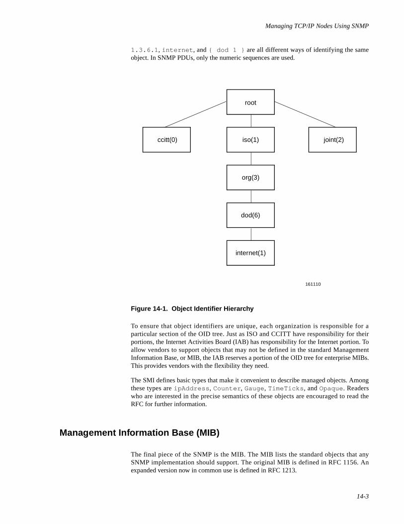
Managing TCP/IP Nodes Using SNMP
14-3
1.3.6.1 , internet , and { dod 1 } are all different ways of identifying the sameobject. In SNMP PDUs, only the numeric sequences are used.
Figure 14-1. Object Identifier Hierarchy
To ensure that object identifiers are unique, each organization is responsible for aparticular section of the OID tree. Just as ISO and CCITT have responsibility for theirportions, the Internet Activities Board (IAB) has responsibility for the Internet portion. Toallow vendors to support objects that may not be defined in the standard ManagementInformation Base, or MIB, the IAB reserves a portion of the OID tree for enterprise MIBs.This provides vendors with the flexibility they need.
The SMI defines basic types that make it convenient to describe managed objects. Amongthese types are ipAddress , Counter , Gauge, TimeTicks , and Opaque. Readerswho are interested in the precise semantics of these objects are encouraged to read theRFC for further information.
Management Information Base (MIB) 14
The final piece of the SNMP is the MIB. The MIB lists the standard objects that anySNMP implementation should support. The original MIB is defined in RFC 1156. Anexpanded version now in common use is defined in RFC 1213.
161110
root
iso(1)ccitt(0) joint(2)
org(3)
dod(6)
internet(1)
Network Administration
14-4
Each object in the MIB has two important characteristics. The first is its OID. The secondis its type. Object types are constructed from the fundamental types defined in the SMI.
The MIB is divided into logically related groups of objects. The important groups are:system , interfaces , tcp , udp , ip , egp , icmp , and snmp.
The system group contains information about the network node. An example of thiswould be the physical location of the node, for example, “R&D Facility, 3rd floor machineroom.”
The interfaces group contains information about network interfaces, such as Ethernetand point-to-point links. Information is kept about such items as interface status (forexample, up or down), packet counts, and so on.
The rest of the groups contain information about the particular protocol to which theyrefer. This includes items like number of packets received with a particular protocol type,and number of packets received with incorrect checksums.
Agents and Management Stations 14
Systems using the SNMP are divided into two categories: agents and managementstations. The management station is the system that issues a query. The agent is the systemthat is being queried.
Although there is no architectural reason that a system cannot have both types offunctionality, most SNMP agents are usually found in dedicated routers and otherspecialized network equipment that is not capable of acting as a management station.
Using the SNMP implementation, time-sharing systems and workstations are able to act asboth agents and management stations.
Traps 14
Although the SNMP is normally a synchronous protocol in which systems poll each otherperiodically, it does include a mechanism for asynchronous events. In the SNMP, these arereferred to as “traps.” Traps are sent by agents to management stations when an abnormalevent, such as an interface state-change, occurs.
Authentication 14
In the current implementation of the SNMP, authentication is based on a field in the PDUcalled the community name. When an agent receives a request, it validates the communityname/IP address pair of the sender by comparing it against a specified list of acceptablemanagement stations. If the sender is not found in the list, the packet is discarded.Optionally, an authentication trap may be sent to a specified group of management sta-tions, informing them that an invalid access has been attempted.
Managing TCP/IP Nodes Using SNMP
14-5
The Internet Engineering Task Force (IETF) is currently working on a proposal for betterauthentication.
Overview of SNMP 14
As stated above, the SNMP product provides the functionality of both agent andmanagement station. A system running the software can monitor other systems and bemonitored as well.
The SNMP agent is implemented as a daemon. There are three configuration filesassociated with the daemon. These files consist of the following: /etc/inet/snmpd.conf , /etc/inet/snmpd.comm , and /etc/inet/snmpd.trap . Theagent is started when the system enters the multi-user state (traditionally run-level 2).Upon start-up, the agent reads configuration information from its configuration files andthen begins listening for SNMP requests on the SNMP port. If configured to send traps,the agent will also notify the appropriate management stations that it is up. This is done bysending a “cold-start” trap to the systems listed in /etc/inet/snmpd.trap .
/etc/inet/snmpd.conf contains the basic information that the agent needs as part ofthe system group. These are the types of the SNMP and TCP/IP software, the name of theperson responsible for the system, the location of the system, and the object identifier ofthe agent. Typically, only the name of the responsible person and the system locationwould need to be changed.
/etc/inet/snmpd.comm contains a list of community/IP address pairs from whomthe agent will accept queries. Along with each pair is an access field that controls whetheraccess is allowed, and if so, whether the access granted is read-only, write, or none (noaccess).
In addition to the agent, there are user commands that provide management stationfunctionality to the system administrator. These are: getid(1M) , getmany(1M) ,getnext(1M) , getone(1M) , getroute(1M) , setany(1M) , and snmp-stat(1M) .
The snmpstat command provides the administrator with an easy way to retrieveinformation such as routing tables, address translation tables, and interface status. Usingsnmpstat , a network administrator can quickly detect error conditions on a misbehavingnetwork node.
The remaining commands provide the administrator with the ability to retrieve or modifyarbitrary objects. Many vendors have their own enterprise MIBs, in addition to thestandard MIB. Since these continually evolve, it may well be the case that a particularnode maintains information above that which is conveniently accessed via snmpstat .The additional commands provide this functionality.
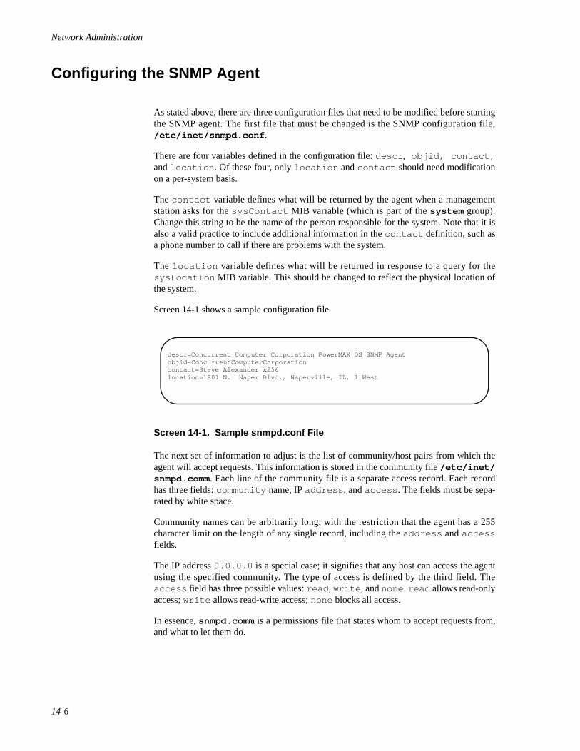
Network Administration
14-6
Configuring the SNMP Agent 14
As stated above, there are three configuration files that need to be modified before startingthe SNMP agent. The first file that must be changed is the SNMP configuration file,/etc/inet/snmpd.conf .
There are four variables defined in the configuration file: descr , objid, contact,and location . Of these four, only location and contact should need modificationon a per-system basis.
The contact variable defines what will be returned by the agent when a managementstation asks for the sysContact MIB variable (which is part of the system group).Change this string to be the name of the person responsible for the system. Note that it isalso a valid practice to include additional information in the contact definition, such asa phone number to call if there are problems with the system.
The location variable defines what will be returned in response to a query for thesysLocation MIB variable. This should be changed to reflect the physical location ofthe system.
Screen 14-1 shows a sample configuration file.
Screen 14-1. Sample snmpd.conf File
The next set of information to adjust is the list of community/host pairs from which theagent will accept requests. This information is stored in the community file /etc/inet/snmpd.comm. Each line of the community file is a separate access record. Each recordhas three fields: community name, IP address , and access . The fields must be sepa-rated by white space.
Community names can be arbitrarily long, with the restriction that the agent has a 255character limit on the length of any single record, including the address and accessfields.
The IP address 0.0.0.0 is a special case; it signifies that any host can access the agentusing the specified community. The type of access is defined by the third field. Theaccess field has three possible values: read , write , and none . read allows read-onlyaccess; write allows read-write access; none blocks all access.
In essence, snmpd.comm is a permissions file that states whom to accept requests from,and what to let them do.
descr=Concurrent Computer Corporation PowerMAX OS SNMP Agentobjid=ConcurrentComputerCorporationcontact=Steve Alexander x256location=1901 N. Naper Blvd., Naperville, IL, 1 West
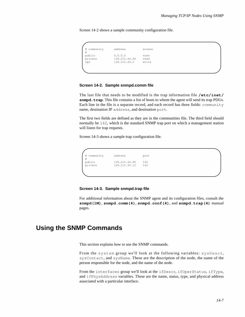
Managing TCP/IP Nodes Using SNMP
14-7
Screen 14-2 shows a sample community configuration file.
Screen 14-2. Sample snmpd.comm file
The last file that needs to be modified is the trap information file /etc/inet/snmpd.trap . This file contains a list of hosts to whom the agent will send its trap PDUs.Each line in the file is a separate record, and each record has three fields: communityname, destination IP address , and destination port .
The first two fields are defined as they are in the communities file. The third field shouldnormally be 162 , which is the standard SNMP trap port on which a management stationwill listen for trap requests.
Screen 14-3 shows a sample trap configuration file.
Screen 14-3. Sample snmpd.trap file
For additional information about the SNMP agent and its configuration files, consult thesnmpd(1M) , snmpd.comm(4) , snmpd.conf(4) , and snmpd.trap(4) manualpages.
Using the SNMP Commands 14
This section explains how to use the SNMP commands.
From the system group we'l l look at the following variables: sysDescr ,sysContact , and sysName. These are the description of the node, the name of theperson responsible for the node, and the name of the node.
From the interfaces group we'll look at the ifDescr , ifOperStatus , ifType ,and ifPhysAddress variables. These are the name, status, type, and physical addressassociated with a particular interface.
# community address access#public 0.0.0.0 noneprivate 128.212.64.90 readops 128.212.64.2 write
# community address port#public 128.212.64.90 162private 128.212.65.12 162
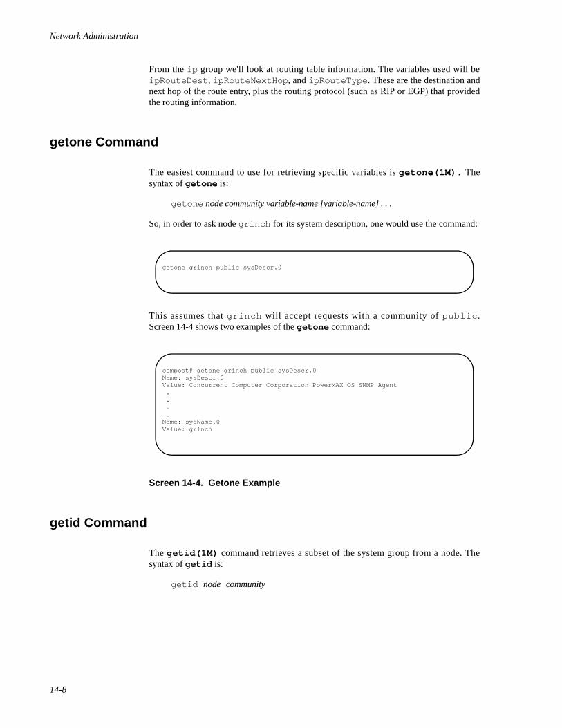
Network Administration
14-8
From the ip group we'll look at routing table information. The variables used will beipRouteDest , ipRouteNextHop , and ipRouteType . These are the destination andnext hop of the route entry, plus the routing protocol (such as RIP or EGP) that providedthe routing information.
getone Command 14
The easiest command to use for retrieving specific variables is getone(1M). Thesyntax of getone is:
getone node community variable-name [variable-name] . . .
So, in order to ask node grinch for its system description, one would use the command:
This assumes that grinch will accept requests with a community of public .Screen 14-4 shows two examples of the getone command:
Screen 14-4. Getone Example
getid Command 14
The getid(1M) command retrieves a subset of the system group from a node. Thesyntax of getid is:
getid node community
getone grinch public sysDescr.0
compost# getone grinch public sysDescr.0Name: sysDescr.0Value: Concurrent Computer Corporation PowerMAX OS SNMP Agent . . . .Name: sysName.0Value: grinch
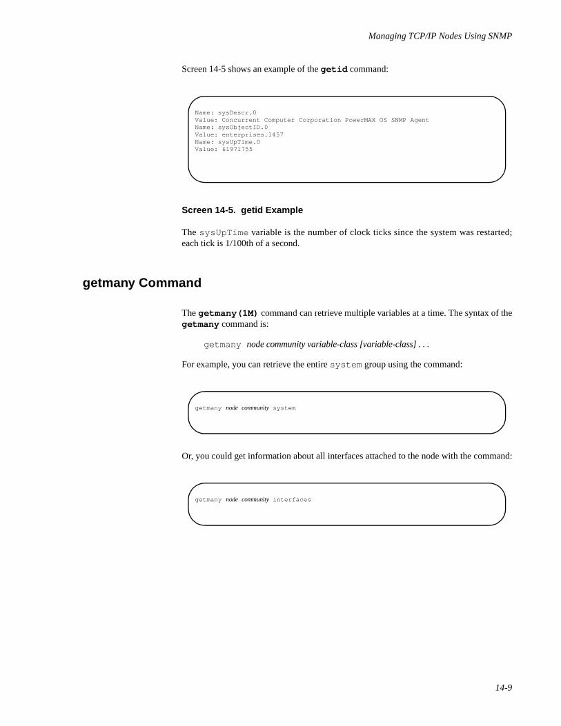
Managing TCP/IP Nodes Using SNMP
14-9
Screen 14-5 shows an example of the getid command:
Screen 14-5. getid Example
The sysUpTime variable is the number of clock ticks since the system was restarted;each tick is 1/100th of a second.
getmany Command 14
The getmany(1M) command can retrieve multiple variables at a time. The syntax of thegetmany command is:
getmany node community variable-class [variable-class] . . .
For example, you can retrieve the entire system group using the command:
Or, you could get information about all interfaces attached to the node with the command:
Name: sysDescr.0Value: Concurrent Computer Corporation PowerMAX OS SNMP AgentName: sysObjectID.0Value: enterprises.1457Name: sysUpTime.0Value: 61971755
getmany node community system
getmany node community interfaces
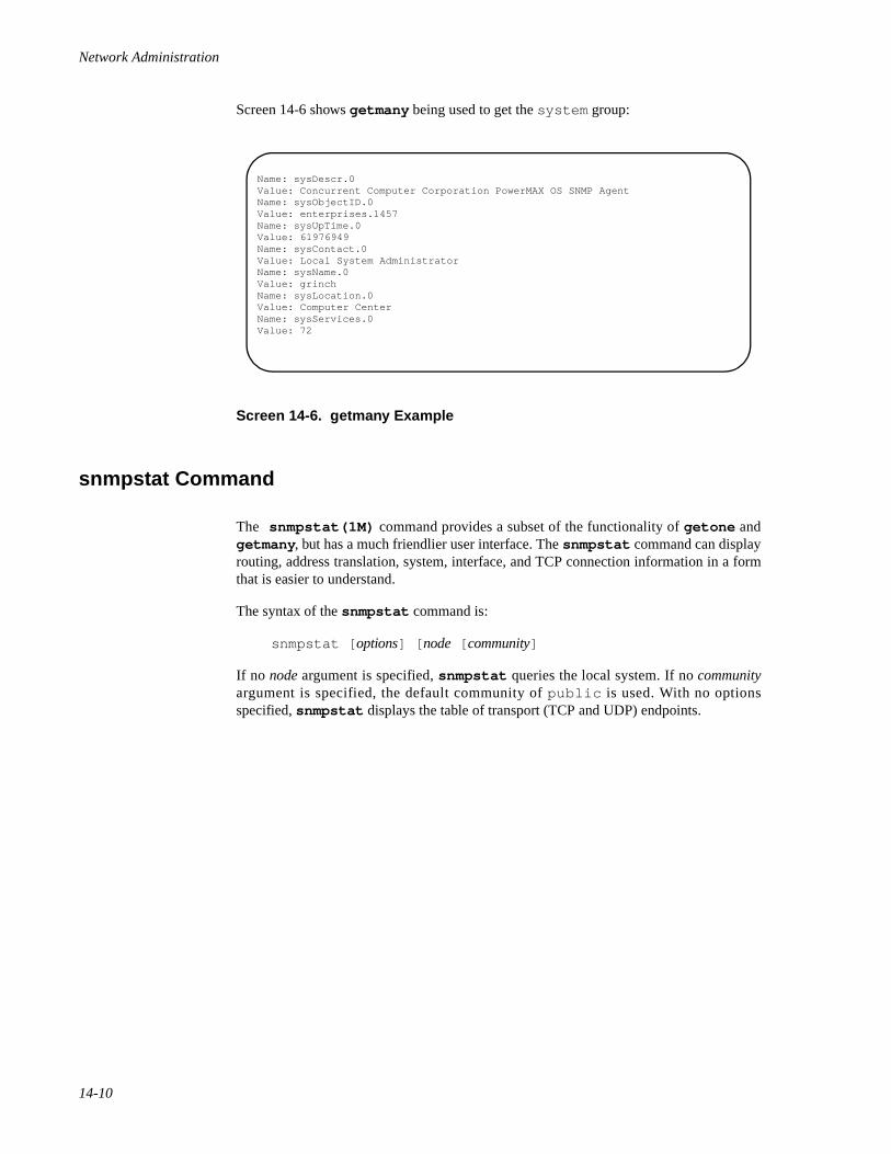
Network Administration
14-10
Screen 14-6 shows getmany being used to get the system group:
Screen 14-6. getmany Example
snmpstat Command 14
The snmpstat(1M) command provides a subset of the functionality of getone andgetmany , but has a much friendlier user interface. The snmpstat command can displayrouting, address translation, system, interface, and TCP connection information in a formthat is easier to understand.
The syntax of the snmpstat command is:
snmpstat [ options] [ node [ community]
If no node argument is specified, snmpstat queries the local system. If no communityargument is specified, the default community of public is used. With no optionsspecified, snmpstat displays the table of transport (TCP and UDP) endpoints.
Name: sysDescr.0Value: Concurrent Computer Corporation PowerMAX OS SNMP AgentName: sysObjectID.0Value: enterprises.1457Name: sysUpTime.0Value: 61976949Name: sysContact.0Value: Local System AdministratorName: sysName.0Value: grinchName: sysLocation.0Value: Computer CenterName: sysServices.0 Value: 72
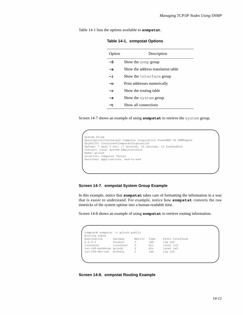
Managing TCP/IP Nodes Using SNMP
14-11
Table 14-1 lists the options available to snmpstat .
Screen 14-7 shows an example of using snmpstat to retrieve the system group.
Screen 14-7. snmpstat System Group Example
In this example, notice that snmpstat takes care of formatting the information in a waythat is easier to understand. For example, notice how snmpstat converts the rawtimeticks of the system uptime into a human-readable time.
Screen 14-8 shows an example of using snmpstat to retrieve routing information.
Screen 14-8. snmpstat Routing Example
Table 14-1. snmpstat Options
Option Description
-S Show the snmp group
-a Show the address translation table
-i Show the interface group
-n Print addresses numerically
-r Show the routing table
-s Show the system group
-t Show all connections
System GroupDescription:Concurrent Computer Corporation PowerMAX OS SNMPAgentObjectID: ConcurrentComputerCorporationUpTime: 7 days 4 hor, 11 minutes, 10 seconds, 12 hundredthsContact: Local System AdministratorName: grinchLocation: Computer CenterServices: applications, end-to-end
compost# snmpstat -r grinch publicRouting tableDestination Gateway Metric Type Proto Interface0.0.0.0 houdini 3 rem rip ie0localhost localhost 0 dir local lo0isc-i88-backbone grinch 0 dir local ie0isc-i88-dev-net mcfeely 2 rem rip ni0
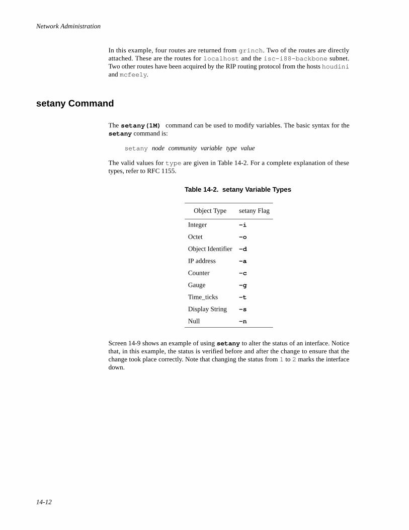
Network Administration
14-12
In this example, four routes are returned from grinch . Two of the routes are directlyattached. These are the routes for localhost and the isc-i88-backbone subnet.Two other routes have been acquired by the RIP routing protocol from the hosts houdiniand mcfeely .
setany Command 14
The setany(1M) command can be used to modify variables. The basic syntax for thesetany command is:
setany node community variable type value
The valid values for type are given in Table 14-2. For a complete explanation of thesetypes, refer to RFC 1155.
Screen 14-9 shows an example of using setany to alter the status of an interface. Noticethat, in this example, the status is verified before and after the change to ensure that thechange took place correctly. Note that changing the status from 1 to 2 marks the interfacedown.
Table 14-2. setany Variable Types
Object Type setany Flag
Integer -i
Octet -o
Object Identifier -d
IP address -a
Counter -c
Gauge -g
Time_ticks -t
Display String -s
Null -n
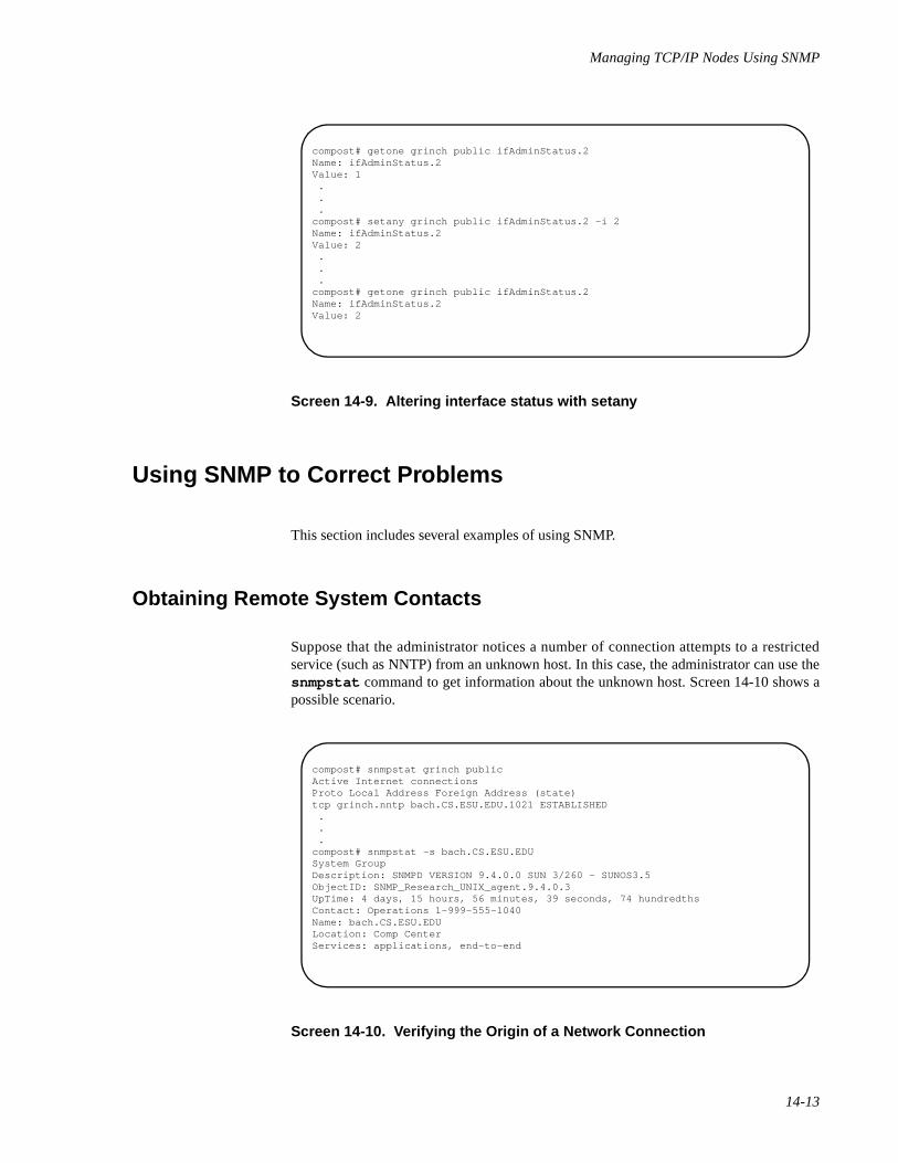
Managing TCP/IP Nodes Using SNMP
14-13
Screen 14-9. Altering interface status with setany
Using SNMP to Correct Problems 14
This section includes several examples of using SNMP.
Obtaining Remote System Contacts 14
Suppose that the administrator notices a number of connection attempts to a restrictedservice (such as NNTP) from an unknown host. In this case, the administrator can use thesnmpstat command to get information about the unknown host. Screen 14-10 shows apossible scenario.
Screen 14-10. Verifying the Origin of a Network Connection
compost# getone grinch public ifAdminStatus.2Name: ifAdminStatus.2Value: 1 . . .compost# setany grinch public ifAdminStatus.2 -i 2Name: ifAdminStatus.2Value: 2 . . .compost# getone grinch public ifAdminStatus.2Name: ifAdminStatus.2Value: 2
compost# snmpstat grinch publicActive Internet connectionsProto Local Address Foreign Address (state)tcp grinch.nntp bach.CS.ESU.EDU.1021 ESTABLISHED . . .compost# snmpstat -s bach.CS.ESU.EDUSystem GroupDescription: SNMPD VERSION 9.4.0.0 SUN 3/260 - SUNOS3.5ObjectID: SNMP_Research_UNIX_agent.9.4.0.3UpTime: 4 days, 15 hours, 56 minutes, 39 seconds, 74 hundredthsContact: Operations 1-999-555-1040Name: bach.CS.ESU.EDULocation: Comp CenterServices: applications, end-to-end
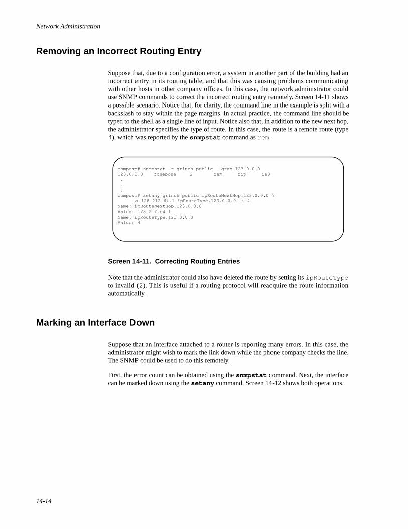
Network Administration
14-14
Removing an Incorrect Routing Entry 14
Suppose that, due to a configuration error, a system in another part of the building had anincorrect entry in its routing table, and that this was causing problems communicatingwith other hosts in other company offices. In this case, the network administrator coulduse SNMP commands to correct the incorrect routing entry remotely. Screen 14-11 showsa possible scenario. Notice that, for clarity, the command line in the example is split with abackslash to stay within the page margins. In actual practice, the command line should betyped to the shell as a single line of input. Notice also that, in addition to the new next hop,the administrator specifies the type of route. In this case, the route is a remote route (type4), which was reported by the snmpstat command as rem.
Screen 14-11. Correcting Routing Entries
Note that the administrator could also have deleted the route by setting its ipRouteTypeto invalid (2). This is useful if a routing protocol will reacquire the route informationautomatically.
Marking an Interface Down 14
Suppose that an interface attached to a router is reporting many errors. In this case, theadministrator might wish to mark the link down while the phone company checks the line.The SNMP could be used to do this remotely.
First, the error count can be obtained using the snmpstat command. Next, the interfacecan be marked down using the setany command. Screen 14-12 shows both operations.
compost# snmpstat -r grinch public | grep 123.0.0.0123.0.0.0 fonebone 2 rem rip ie0 . . .compost# setany grinch public ipRouteNextHop.123.0.0.0 \
-a 128.212.64.1 ipRouteType.123.0.0.0 -i 4Name: ipRouteNextHop.123.0.0.0Value: 128.212.64.1Name: ipRouteType.123.0.0.0Value: 4
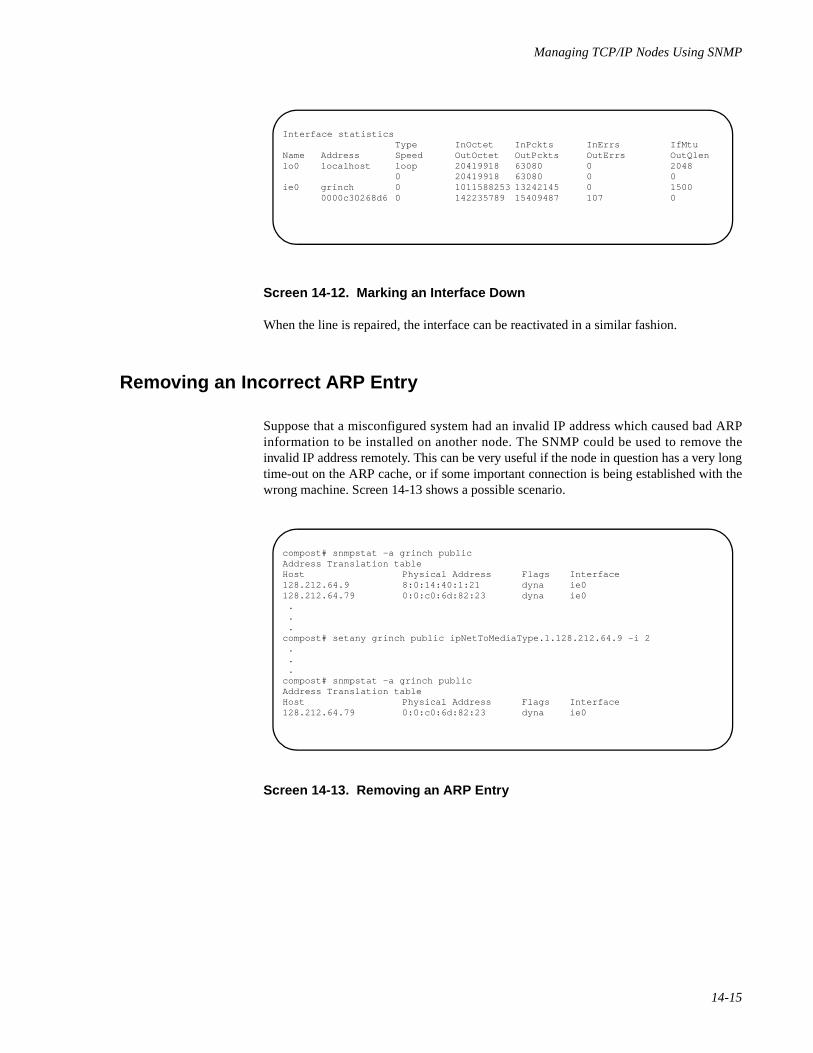
Managing TCP/IP Nodes Using SNMP
14-15
Screen 14-12. Marking an Interface Down
When the line is repaired, the interface can be reactivated in a similar fashion.
Removing an Incorrect ARP Entry 14
Suppose that a misconfigured system had an invalid IP address which caused bad ARPinformation to be installed on another node. The SNMP could be used to remove theinvalid IP address remotely. This can be very useful if the node in question has a very longtime-out on the ARP cache, or if some important connection is being established with thewrong machine. Screen 14-13 shows a possible scenario.
Screen 14-13. Removing an ARP Entry
Interface statisticsType InOctet InPckts InErrs IfMtu
Name Address Speed OutOctet OutPckts OutErrs OutQlenlo0 localhost loop 20419918 63080 0 2048
0 20419918 63080 0 0ie0 grinch 0 1011588253 13242145 0 1500
0000c30268d6 0 142235789 15409487 107 0
compost# snmpstat -a grinch publicAddress Translation tableHost Physical Address Flags Interface128.212.64.9 8:0:14:40:1:21 dyna ie0128.212.64.79 0:0:c0:6d:82:23 dyna ie0 . . .compost# setany grinch public ipNetToMediaType.1.128.212.64.9 -i 2 . . .compost# snmpstat -a grinch publicAddress Translation tableHost Physical Address Flags Interface128.212.64.79 0:0:c0:6d:82:23 dyna ie0

Network Administration
14-16
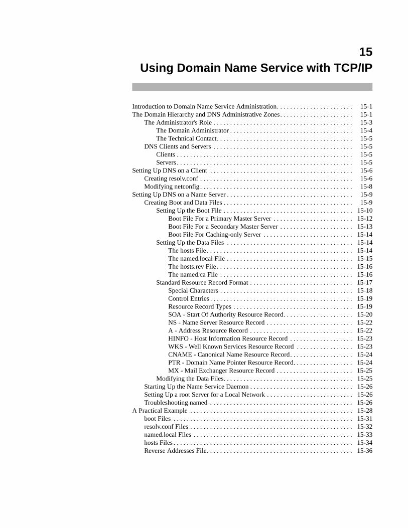
15Using Domain Name Service with TCP/IP
Introduction to Domain Name Service Administration. . . . . . . . . . . . . . . . . . . . . . . 15-1The Domain Hierarchy and DNS Administrative Zones. . . . . . . . . . . . . . . . . . . . . . 15-1
The Administrator's Role . . . . . . . . . . . . . . . . . . . . . . . . . . . . . . . . . . . . . . . . . . 15-3The Domain Administrator . . . . . . . . . . . . . . . . . . . . . . . . . . . . . . . . . . . . . 15-4The Technical Contact. . . . . . . . . . . . . . . . . . . . . . . . . . . . . . . . . . . . . . . . . 15-5
DNS Clients and Servers . . . . . . . . . . . . . . . . . . . . . . . . . . . . . . . . . . . . . . . . . . 15-5Clients . . . . . . . . . . . . . . . . . . . . . . . . . . . . . . . . . . . . . . . . . . . . . . . . . . . . . 15-5Servers. . . . . . . . . . . . . . . . . . . . . . . . . . . . . . . . . . . . . . . . . . . . . . . . . . . . . 15-5
Setting Up DNS on a Client . . . . . . . . . . . . . . . . . . . . . . . . . . . . . . . . . . . . . . . . . . . 15-6Creating resolv.conf . . . . . . . . . . . . . . . . . . . . . . . . . . . . . . . . . . . . . . . . . . . . . . 15-6Modifying netconfig . . . . . . . . . . . . . . . . . . . . . . . . . . . . . . . . . . . . . . . . . . . . . . 15-8
Setting Up DNS on a Name Server . . . . . . . . . . . . . . . . . . . . . . . . . . . . . . . . . . . . . . 15-9Creating Boot and Data Files . . . . . . . . . . . . . . . . . . . . . . . . . . . . . . . . . . . . . . . 15-9
Setting Up the Boot File . . . . . . . . . . . . . . . . . . . . . . . . . . . . . . . . . . . . . . . 15-10Boot File For a Primary Master Server . . . . . . . . . . . . . . . . . . . . . . . . 15-12Boot File For a Secondary Master Server . . . . . . . . . . . . . . . . . . . . . . 15-13Boot File For Caching-only Server . . . . . . . . . . . . . . . . . . . . . . . . . . . 15-14
Setting Up the Data Files . . . . . . . . . . . . . . . . . . . . . . . . . . . . . . . . . . . . . . 15-14The hosts File . . . . . . . . . . . . . . . . . . . . . . . . . . . . . . . . . . . . . . . . . . . . 15-14The named.local File . . . . . . . . . . . . . . . . . . . . . . . . . . . . . . . . . . . . . . 15-15The hosts.rev File . . . . . . . . . . . . . . . . . . . . . . . . . . . . . . . . . . . . . . . . . 15-16The named.ca File . . . . . . . . . . . . . . . . . . . . . . . . . . . . . . . . . . . . . . . . 15-16
Standard Resource Record Format . . . . . . . . . . . . . . . . . . . . . . . . . . . . . . . 15-17Special Characters . . . . . . . . . . . . . . . . . . . . . . . . . . . . . . . . . . . . . . . . 15-18Control Entries . . . . . . . . . . . . . . . . . . . . . . . . . . . . . . . . . . . . . . . . . . . 15-19Resource Record Types . . . . . . . . . . . . . . . . . . . . . . . . . . . . . . . . . . . . 15-19SOA - Start Of Authority Resource Record. . . . . . . . . . . . . . . . . . . . . 15-20NS - Name Server Resource Record . . . . . . . . . . . . . . . . . . . . . . . . . . 15-22A - Address Resource Record . . . . . . . . . . . . . . . . . . . . . . . . . . . . . . . 15-22HINFO - Host Information Resource Record . . . . . . . . . . . . . . . . . . . 15-23WKS - Well Known Services Resource Record . . . . . . . . . . . . . . . . . 15-23CNAME - Canonical Name Resource Record. . . . . . . . . . . . . . . . . . . 15-24PTR - Domain Name Pointer Resource Record. . . . . . . . . . . . . . . . . . 15-24MX - Mail Exchanger Resource Record . . . . . . . . . . . . . . . . . . . . . . . 15-25
Modifying the Data Files. . . . . . . . . . . . . . . . . . . . . . . . . . . . . . . . . . . . . . . 15-25Starting Up the Name Service Daemon . . . . . . . . . . . . . . . . . . . . . . . . . . . . . . . 15-26Setting Up a root Server for a Local Network . . . . . . . . . . . . . . . . . . . . . . . . . . 15-26Troubleshooting named . . . . . . . . . . . . . . . . . . . . . . . . . . . . . . . . . . . . . . . . . . . 15-26
A Practical Example . . . . . . . . . . . . . . . . . . . . . . . . . . . . . . . . . . . . . . . . . . . . . . . . . 15-28boot Files . . . . . . . . . . . . . . . . . . . . . . . . . . . . . . . . . . . . . . . . . . . . . . . . . . . . . . 15-31resolv.conf Files . . . . . . . . . . . . . . . . . . . . . . . . . . . . . . . . . . . . . . . . . . . . . . . . . 15-32named.local Files . . . . . . . . . . . . . . . . . . . . . . . . . . . . . . . . . . . . . . . . . . . . . . . . 15-33hosts Files . . . . . . . . . . . . . . . . . . . . . . . . . . . . . . . . . . . . . . . . . . . . . . . . . . . . . . 15-34Reverse Addresses File. . . . . . . . . . . . . . . . . . . . . . . . . . . . . . . . . . . . . . . . . . . . 15-36

Network Administration
15-1
15Chapter 15Using Domain Name Service with TCP/IP
151515
Introduction to Domain Name Service Administration 15
Domain Name Service (DNS) is an application layer protocol that is part of the standardTCP/IP protocol suite. Specifically, DNS is a naming service; it obtains and providesinformation about hosts on a network.
Domain Name Service performs naming between hosts within your local administrativedomain and across domain boundaries. It is distributed among a set of servers, commonlyknown as name servers, each of which implements DNS by running a daemon callednamed.
NOTE
The named daemon is also called the Berkeley Internet NameDomain service, or BIND, because it was developed at Universityof California at Berkeley.
On the client's side, DNS is implemented through the resolver. The resolver is neither adaemon nor a particular program; rather, it is a library compiled into applications that needto know machine names. The resolver's function is to resolve users' queries. To do that, itqueries a name server, which then returns either the requested information or a referral toanother server.
DNS is dependent on the hierarchical structure of the Internet, and adds to that structurethe concept of domain zones. This chapter describes the organization of domains as itrelates to DNS on the Internet, then tells you how to set up and maintain DNS on your net-work machines.
The Domain Hierarchy and DNS Administrative Zones 15
Domain names used by DNS reflect the hierarchical organization of the public networks.Before you set up DNS for your organization, you should understand the organization ofthe network, your place in the overall structure of the network, and how domain namesreflect that structure.
For information about the structure of the Internet and domain naming conventions, seeChapter 18, "Obtaining Domain Names".
Network Administration
15-2
The Domain Name Service introduces the concept of zones to the Internet network model.A zone is a hierarchical community of hosts, administered by a single authority and servedby a set of name servers. This community can include individual hosts, plus every nameserver and its clients (a subzone) nested beneath the authoritative set of name servers forthe zone. Zones usually represent administrative boundaries, such as your localadministrative domain. However, a zone is not limited to just one administrative domain.A zone is a domain, plus all or some of the domains under it.
Figure 15-1 shows how some fictional zones might be delegated. The illustration showsfour zones: the root zone, served by the Internet root domain name servers, and threezones served by name servers at domain sun.COM. The dotted lines point to the areasmaking up each zone.
Zones take their names from the label of the domain at the top of the zone hierarchy. InFigure 15-1, the names of the four domains within dotted lines are:
sun.COM venus.sun.COM mars.sun.COM .
where the “.” (dot) at the end of the line signifies the root zone. Zone sun.COM takes itsname from the label of the second level domain sun.COM. However, zone sun.COM doesnot have the same administrative authority as the domain of the same name. Zonesun.COM consists only of:
• domain sun
• local administrative domain earth
• subdomains telstar , moon, eurostar , france , greece , and uk
The zone sun.COM does not include domains venus and mars . They have their ownseparately administered zones: venus.sun.COM and mars.sun.COM , respectively.However, venus and mars are part of the sun.COM domain hierarchy.
The domain hierarchy and name space described so far keeps track of information by hostname. This enables the named daemon to perform name-to-address mapping.
In addition, there is a special domain recognized by DNS called IN-ADDR.ARPA, whichfacilitates address-to-name mapping. IN-ADDR.ARPA contains essentially the sameinformation as the hosts name space, but it is expressed in terms of IP addresses.
A name in the IN-ADDR.ARPA domain has four labels preceding it, corresponding to thefour octets of an IP address. This host address is listed from right to left. For example, ahost whose IP address is 128.32.0.4 has the following IN-ADDR.ARPA domain name:
4.0.32.128.IN-ADDR.ARPA.
Therefore, if named knows the IP address of a host, it can find out the host's fullyqualified domain name by consulting a file representing the IN-ADDR.ARPA domain.(This file, commonly called hosts.rev , is explained in a later section.)
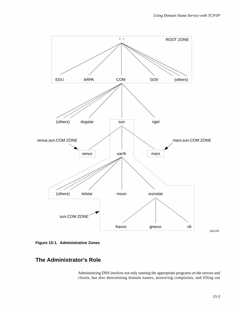
Using Domain Name Service with TCP/IP
15-3
Figure 15-1. Administrative Zones
The Administrator's Role 15
Administering DNS involves not only running the appropriate programs on the servers andclients, but also determining domain names, answering complaints, and filling out
" "
EDU ARPA COM GOV
ROOT ZONE
(others)
(others) rigelsundogstar
(others) eurostar
uk161120
moontelstar
greecefrance
marsearthvenus
mars.sun.COM ZONEvenus.sun.COM ZONE
sun.COM ZONE
Network Administration
15-4
registration and other forms, should you join a public network. This section contains over-all procedures for setting up DNS, based on the responsibilities you might have as a DNSadministrator.
Your administrative responsibilities for DNS depend on your domain's position within theoverall network hierarchy. For example, managing one set of name servers in a smalladministrative domain entails less responsibility than managing the authoritative set for alarge zone. Responsibilities depend on whether you are the chief authority for a domain orzone, or an administrator reporting to the chief authority.
The Network Information Center (NIC) divides administrators on the Internet into domainadministrators, who have primary responsibility for a domain, and technical contacts, whowork with domain administrators to maintain a zone. Descriptions of each position appearbelow.
The Domain Administrator 15
The domain administrator (DA) is a coordinator, manager, and technician for a second-level or lower domain. The DA's responsibilities include the following:
• Registering the domain.
If your domain is going to be on a public network, you must register it (ifyou have not done so already). The domain must have a unique namewithin its level of the network hierarchy. To register your domain with theInternet, obtain the Domain Registration Form from NIC and complete itaccording to the instructions in the chapter “Obtaining Domain Names”. Tojoin other public networks, contact the organization in charge of the net-work and request the appropriate domain registration form.
NOTE
To belong to multiple networks such as the Internet, BITNET, orCSNET, you need to register with only one network, as domainnames are independent of a network's physical topology.
• Naming hosts and verifying that names within the domain are unique.
At many sites, users name their individual hosts while the administratorsname the servers. The administrator should ensure that there are noduplicate names within a zone.
• Understanding the functioning of the name servers and making sure thedata is current at all times.
This includes either setting up the DNS-related files and programs, ordelegating this authority to other technically competent people (such as thetechnical contact). This chapter should provide you with the basicinformation you need for understanding DNS. However, as the domainadministrator, you should gain more specific technical knowledge of yourparticular network. Contact the public network to which you belong andask for technical papers regarding it.
Using Domain Name Service with TCP/IP
15-5
The Technical Contact 15
The primary responsibility of a technical contact is to maintain DNS programs and filesfor a zone and to keep the zone's name servers running. Technical contacts interact withtheir domain administrators and with DA's of other domains to solve network problems.
DNS Clients and Servers 15
As mentioned earlier, there are two sides to DNS: clients running the resolver and nameservers running the named daemon.
Clients 15
A name server running named can also run the resolver; therefore, there can be two kindsof clients:
• client-only
• client/server
A client-only client does not run the named daemon; instead, it consults the resolver,which provides a list of possible name serving machines to which queries should bedirected.
A client/server is a machine that uses the domain name service provided by named inorder to resolve a user's queries. However, if the daemon dies or hangs, the client/servermight be able to solve queries through its resolver.
Servers 15
You implement DNS for a zone not on a single server, but on a set of servers. This set mustinclude two master servers, and may or may not include other servers.
• Master servers
The master name servers maintain all the data corresponding to the zone,making them the authority for that zone. These are commonly calledauthoritative name servers. The data corresponding to any given zone mustbe available on at least two authoritative servers. You should designate onename server as the primary master server and at least one as a secondarymaster server, to act as a backup if the primary is unavailable or over-loaded.
The primary master server is the name server where you make changes forthe zone. This server loads the master copy of its data from disk when itstarts up named. The primary server may also delegate authority to otherservers in its zone, as well as to servers outside of it.
The secondary master server is a name server that maintains a copy of thedata for the zone. The primary server sends its data and delegates its
Network Administration
15-6
authority to the secondary server. When the secondary server boots named,it requests all the data for the given zone from the primary. The secondaryserver then periodically checks with the primary to see if it needs to updateits data.
A server may function as a master for multiple zones: as a primary forsome zones, and as a secondary for others.
A server at the root level of the network is called a root domain nameserver. On the Internet, root domain name servers are maintained by theNIC. If a network is not connected to the Internet, primary and secondaryname servers must be set up and administered for the root level of thelocal network.
• Caching and caching-only servers
All name servers are caching servers. This means that the name servercaches received information until the data expires. (The expiration processis regulated by the time to live field attached to the data when it isreceived from another server.)
Additionally, you can set up a caching-only server that is not authoritativefor any zone. This server handles queries and asks other name servers whohave the authority for the information needed. But the caching-only serverdoes not maintain any authoritative data itself.
Setting Up DNS on a Client 15
Setting up DNS on a client involves performing the following two tasks:
1. Creating the file resolv.conf
2. Modifying the file netconfig
NOTE
If you are setting up DNS on a name server, you need to completethese tasks, in addition to setting up boot and data files and editingthe startup script.
Creating resolv.conf 15
The domain name server uses several files to load its database. At the resolver level, itneeds a file called /etc/resolv.conf , which lists the addresses of the servers wherethe resolver can obtain the information needed. Whenever the resolver has to find theaddress of a host (or the name corresponding to an address) it builds a query package andsends it to the name servers it knows of (from /etc/resolv.conf ).
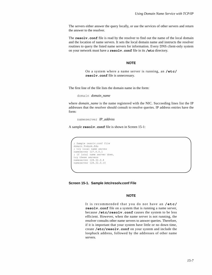
Using Domain Name Service with TCP/IP
15-7
The servers either answer the query locally, or use the services of other servers and returnthe answer to the resolver.
The resolv.conf file is read by the resolver to find out the name of the local domainand the location of name servers. It sets the local domain name and instructs the resolverroutines to query the listed name servers for information. Every DNS client-only systemon your network must have a resolv.conf file in its /etc directory.
NOTE
On a system where a name server is running, an /etc/resolv.conf file is unnecessary.
The first line of the file lists the domain name in the form:
domain domain_name
where domain_name is the name registered with the NIC. Succeeding lines list the IPaddresses that the resolver should consult to resolve queries. IP address entries have theform:
nameserver IP_address
A sample resolv.conf file is shown in Screen 15-1:
Screen 15-1. Sample /etc/resolv.conf File
NOTE
I t i s recommended tha t y ou do no t have an /e tc /resolv.conf file on a system that is running a name server,because /etc/resolv.conf causes the system to be lessefficient. However, when the name server is not running, theresolver consults other name servers to answer queries. Therefore,if it is important that your system have little or no down time,create /etc/resolv.conf on your system and include theloopback address, followed by the addresses of other nameservers.
; Sample resolv.conf filedomain Podunk.Edu; try local name servernameserver 127.0.0.1; if local name server down,try these serversnameserver 128.32.0.4nameserver 128.32.0.10
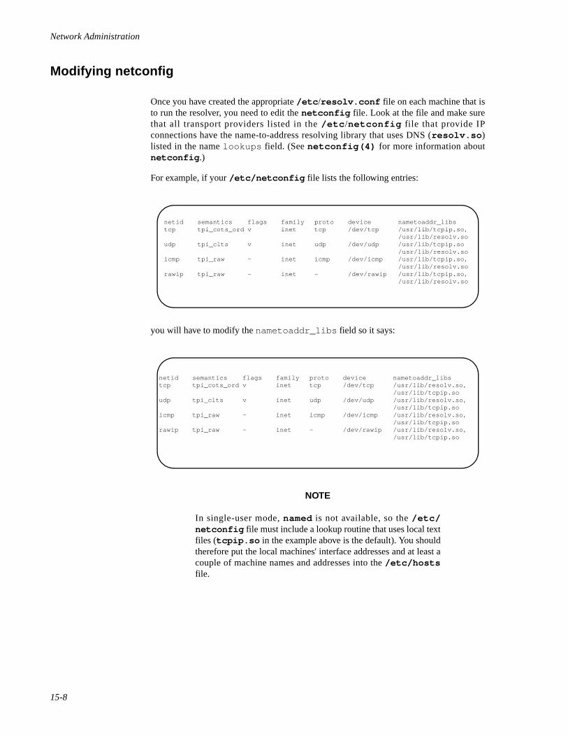
Network Administration
15-8
Modifying netconfig 15
Once you have created the appropriate /etc /resolv.conf file on each machine that isto run the resolver, you need to edit the netconfig file. Look at the file and make surethat all transport providers listed in the /etc /netconfig file that provide IPconnections have the name-to-address resolving library that uses DNS (resolv.so )listed in the name lookups field. (See netconfig(4) for more information aboutnetconfig .)
For example, if your /etc/netconfig file lists the following entries:
you will have to modify the nametoaddr_libs field so it says:
NOTE
In single-user mode, named is not available, so the /etc/netconfig file must include a lookup routine that uses local textfiles (tcpip.so in the example above is the default). You shouldtherefore put the local machines' interface addresses and at least acouple of machine names and addresses into the /etc/hostsfile.
netid semantics flags family proto device nametoaddr_libstcp tpi_cots_ord v inet tcp /dev/tcp /usr/lib/tcpip.so,
/usr/lib/resolv.soudp tpi_clts v inet udp /dev/udp /usr/lib/tcpip.so
/usr/lib/resolv.soicmp tpi_raw - inet icmp /dev/icmp /usr/lib/tcpip.so,
/usr/lib/resolv.sorawip tpi_raw - inet - /dev/rawip /usr/lib/tcpip.so,
/usr/lib/resolv.so
netid semantics flags family proto device nametoaddr_libstcp tpi_cots_ord v inet tcp /dev/tcp /usr/lib/resolv.so,
/usr/lib/tcpip.soudp tpi_clts v inet udp /dev/udp /usr/lib/resolv.so,
/usr/lib/tcpip.soicmp tpi_raw - inet icmp /dev/icmp /usr/lib/resolv.so,
/usr/lib/tcpip.sorawip tpi_raw - inet - /dev/rawip /usr/lib/resolv.so,
/usr/lib/tcpip.so
Using Domain Name Service with TCP/IP
15-9
Setting Up DNS on a Name Server 15
Because name servers also use the resolver, it is necessary to set up /etc/netconfigand, optionally /etc/resolv.conf , as described in the section “Setting Up DNS on aClient” on page 15-6. If you create an /etc/resolv.conf file on a name server, youshould include the line:
nameserver 127.0.0.1
before any other nameserver lines. Next, you need to create the boot and data files thatnamed needs. Instructions for performing both of these tasks appear in this section.
If your local network is not on the Internet, you must set up primary and secondary serversin the root-level domain on the local network. Instructions for setting up a root domainname server appear at the end of this section.
Creating Boot and Data Files 15
In addition to the daemon named, DNS on a name server consists of a boot file and localdata files. The default location of the boot file is /etc/inet/named.boot . Commonnames for the local data files are named.ca , named.local , host s, and hosts.rev .In the descriptions of these files that follow, these names are used. However, you can namethese files whatever you like. In fact, it is recommended that you use names other than theones used in this guide, to avoid confusion with files with similar names.
• named.boot
The boot file named.boot establishes the server as a primary, asecondary, or a caching-only name server. It also specifies the zones overwhich the server has authority, and which data files it should read to get itsinitial data.
The boot file is read by named when the daemon is started by the server'sstartup script /etc/inet/rc.inet . The boot file directs named eitherto other servers, or to local data files for a specified domain.
• named.ca
The named.ca file establishes the names of root servers and lists theiraddresses. If you are connected to the Internet, named.ca lists the Internetname servers; otherwise, it lists the root domain name servers for yourlocal network. named cycles through the list of servers until it contacts oneof them. It then obtains from that server the current list of root servers,which it uses to update named.ca .
To avoid confusion with the caching process, with which this has very littleto do, you may want to call your file something like named.root orboot.root .
Network Administration
15-10
• named.local
The named.local file specifies the address for the local loopbackinterface, or localhost, with the network address 127.0.0.1 . The nameof this file is specified in the named.boot file. As with all other files, itcan be called something other than the name used in this guide.
• hosts
The hosts file contains all the data about the machines in the local zone.The name of this file is specified in the named.boot file. To avoidconfusion with /etc/hosts , name the file something other than hosts .You may want to give the file name the suffix zone; in the followingillustration, the file is called A.puzone .
• hosts.rev
The hosts.rev file specifies a zone in the IN-ADDR.ARPA domain (thespecial domain that allows inverse mapping). The name of this file isspecified in the named.boot file. In the illustration, the file is calledpuhosts.rev .
The relationship between the named.boot file and the data files (or, alternatively, otherservers) is illustrated in Figure 15-2.
Setting Up the Boot File 15
The contents of the boot file vary, depending on the type of server. This section describesboot files for primary and secondary master servers and caching-only servers.
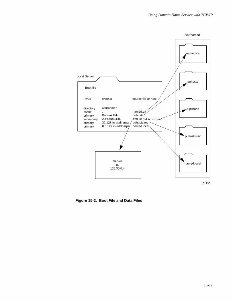
Using Domain Name Service with TCP/IP
15-11
Figure 15-2. Boot File and Data Files
;; Boot file;
; type;
directorycacheprimarysecondaryprimaryprimary
domain
/var/named.Podunk.EduA.Podunk.Edu32.128.in-addr.arpa0.0.127.in-addr.arpa
source file or host
named.capuhosts128.30.0.4 A.puzonepuhosts.revnamed.local
/var/named
Local Server
named.ca
puhosts
A.puzone
puhosts.rev
named.local
161130
Serverat
128.30.0.4
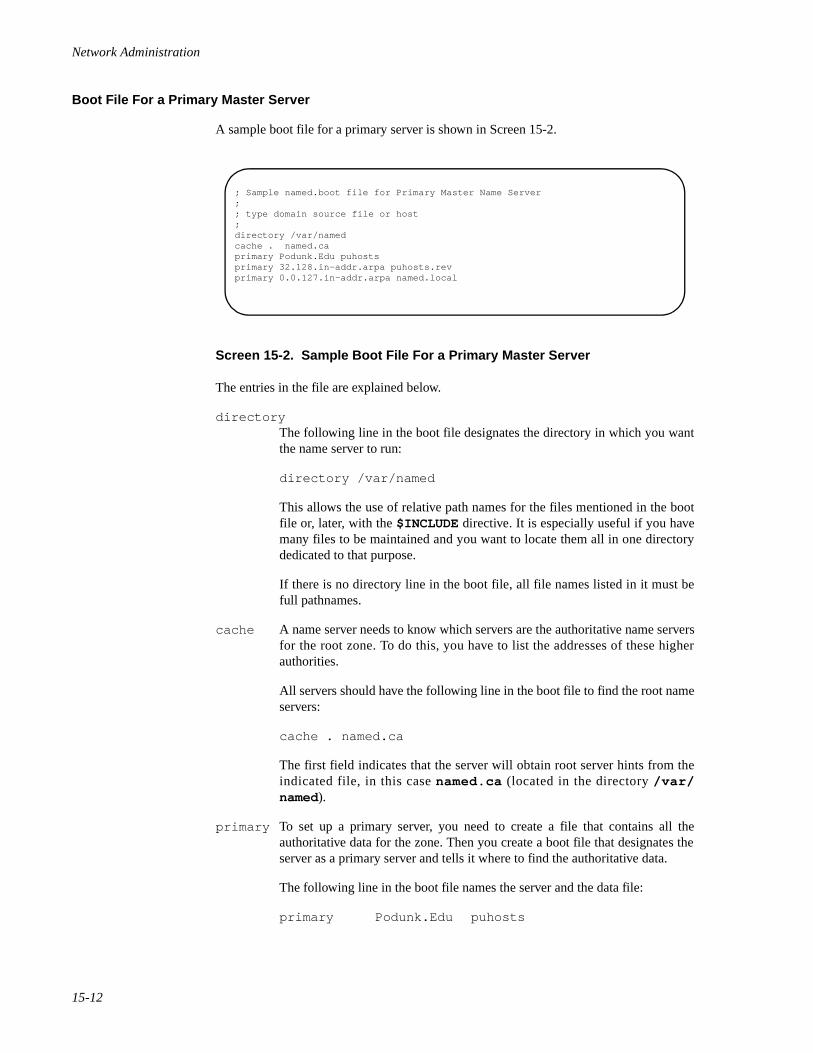
Network Administration
15-12
Boot File For a Primary Master Server 15
A sample boot file for a primary server is shown in Screen 15-2.
Screen 15-2. Sample Boot File For a Primary Master Server
The entries in the file are explained below.
directoryThe following line in the boot file designates the directory in which you wantthe name server to run:
directory /var/named
This allows the use of relative path names for the files mentioned in the bootfile or, later, with the $INCLUDE directive. It is especially useful if you havemany files to be maintained and you want to locate them all in one directorydedicated to that purpose.
If there is no directory line in the boot file, all file names listed in it must befull pathnames.
cache A name server needs to know which servers are the authoritative name serversfor the root zone. To do this, you have to list the addresses of these higherauthorities.
All servers should have the following line in the boot file to find the root nameservers:
cache . named.ca
The first field indicates that the server will obtain root server hints from theindicated file, in this case named.ca (located in the directory /var/named).
primary To set up a primary server, you need to create a file that contains all theauthoritative data for the zone. Then you create a boot file that designates theserver as a primary server and tells it where to find the authoritative data.
The following line in the boot file names the server and the data file:
primary Podunk.Edu puhosts
; Sample named.boot file for Primary Master Name Server;; type domain source file or host;directory /var/namedcache . named.caprimary Podunk.Edu puhostsprimary 32.128.in-addr.arpa puhosts.revprimary 0.0.127.in-addr.arpa named.local
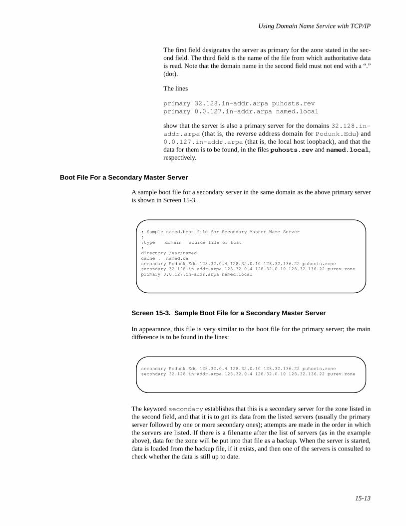
Using Domain Name Service with TCP/IP
15-13
The first field designates the server as primary for the zone stated in the sec-ond field. The third field is the name of the file from which authoritative datais read. Note that the domain name in the second field must not end with a “.”(dot).
The lines
primary 32.128.in-addr.arpa puhosts.revprimary 0.0.127.in-addr.arpa named.local
show that the server is also a primary server for the domains 32.128.in-addr.arpa (that is, the reverse address domain for Podunk.Edu ) and0.0.127.in-addr.arpa (that is, the local host loopback), and that thedata for them is to be found, in the files puhosts.rev and named.local ,respectively.
Boot File For a Secondary Master Server 15
A sample boot file for a secondary server in the same domain as the above primary serveris shown in Screen 15-3.
Screen 15-3. Sample Boot File for a Secondary Master Server
In appearance, this file is very similar to the boot file for the primary server; the maindifference is to be found in the lines:
The keyword secondary establishes that this is a secondary server for the zone listed inthe second field, and that it is to get its data from the listed servers (usually the primaryserver followed by one or more secondary ones); attempts are made in the order in whichthe servers are listed. If there is a filename after the list of servers (as in the exampleabove), data for the zone will be put into that file as a backup. When the server is started,data is loaded from the backup file, if it exists, and then one of the servers is consulted tocheck whether the data is still up to date.
; Sample named.boot file for Secondary Master Name Server;;type domain source file or host;directory /var/namedcache . named.casecondary Podunk.Edu 128.32.0.4 128.32.0.10 128.32.136.22 puhosts.zonesecondary 32.128.in-addr.arpa 128.32.0.4 128.32.0.10 128.32.136.22 purev.zoneprimary 0.0.127.in-addr.arpa named.local
secondary Podunk.Edu 128.32.0.4 128.32.0.10 128.32.136.22 puhosts.zonesecondary 32.128.in-addr.arpa 128.32.0.4 128.32.0.10 128.32.136.22 purev.zone
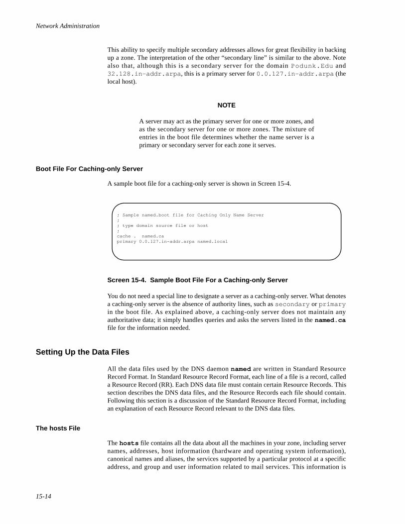
Network Administration
15-14
This ability to specify multiple secondary addresses allows for great flexibility in backingup a zone. The interpretation of the other “secondary line” is similar to the above. Notealso that, although this is a secondary server for the domain Podunk.Edu and32.128.in-addr.arpa , this is a primary server for 0.0.127.in-addr.arpa (thelocal host).
NOTE
A server may act as the primary server for one or more zones, andas the secondary server for one or more zones. The mixture ofentries in the boot file determines whether the name server is aprimary or secondary server for each zone it serves.
Boot File For Caching-only Server 15
A sample boot file for a caching-only server is shown in Screen 15-4.
Screen 15-4. Sample Boot File For a Caching-only Server
You do not need a special line to designate a server as a caching-only server. What denotesa caching-only server is the absence of authority lines, such as secondary or primaryin the boot file. As explained above, a caching-only server does not maintain anyauthoritative data; it simply handles queries and asks the servers listed in the named.cafile for the information needed.
Setting Up the Data Files 15
All the data files used by the DNS daemon named are written in Standard ResourceRecord Format. In Standard Resource Record Format, each line of a file is a record, calleda Resource Record (RR). Each DNS data file must contain certain Resource Records. Thissection describes the DNS data files, and the Resource Records each file should contain.Following this section is a discussion of the Standard Resource Record Format, includingan explanation of each Resource Record relevant to the DNS data files.
The hosts File 15
The hosts file contains all the data about all the machines in your zone, including servernames, addresses, host information (hardware and operating system information),canonical names and aliases, the services supported by a particular protocol at a specificaddress, and group and user information related to mail services. This information is
; Sample named.boot file for Caching Only Name Server;; type domain source file or host;cache . named.caprimary 0.0.127.in-addr.arpa named.local

Using Domain Name Service with TCP/IP
15-15
represented in the records NS, A, HINFO, CNAME, WKS, MX, MB, MR, and MG. The file alsoincludes the SOA record, which indicates the start of a zone and includes the name of thehost on which the hosts data file resides. A sample hosts file is shown in Screen 15-5.
Screen 15-5. Sample hosts File
The named.local File 15
The named.local file sets up the local loopback interface for your name server. It needsto contain the host name of the machine, plus a pointer to the host name localhost ,which represents the loopback mechanism. The server name is indicated in the NSresource record, and the pointer to localhost by the PTR record. The file also needs toinclude a SOA record, which indicates the start of a zone, and includes the name of thehost on which the named.local data file resides.
; sample hosts file@ IN SOA ourfox.Sample.Edu. kjd.monet.Sample.Edu. ( 1.1 ; Serial
10800 ; Refresh 1800 ; Retry 3600000 ; Expire 86400 ) ; Minimum IN NS ourarpa.Sample.Edu. IN NS ourfox.Sample.Edu.ourarpa IN A 128.32.0.4 IN A 10.0.0.78 IN HINFO 3B2 UNIXarpa IN CNAME ourarpaernie IN A 128.32.0.6 IN HINFO 3B2 UNIXourernie IN CNAME erniemonet IN A 128.32.7
IN A 128.32.130.6 IN HINFO Sun-4/110 UNIXourmonet IN CNAME monetourfox IN A 10.2.0.78 IN A 128.32.0.10 IN HINFO Sun-4/110 UNIX IN WKS 128.32.0.10 UDP syslog route timed domain IN WKS 128.32.0.10 TCP ( echo telnet discard rpc sftp uucp-path systat daytime netstat qotd nntp link chargen ftp auth time whois mtp pop rje finger smtp supdup hostnames domain nameserver )fox IN CNAME ourfoxtoybox IN A 128.32.131.119 IN HINFO 3B2 UNIXtoybox IN MX 0 monet.Sample.Edumiriam IN MB vineyd.Neighbor.COM.postmistress IN MR miriambind IN MINFO bind-request kjd.Sample.Edu. IN MG ralph.Sample.Edu. IN MG zhou.Sample.Edu. IN MG painter.Sample.Edu. IN MG riggle.Sample.Edu. IN MG terry.pa.Xerox.Com.
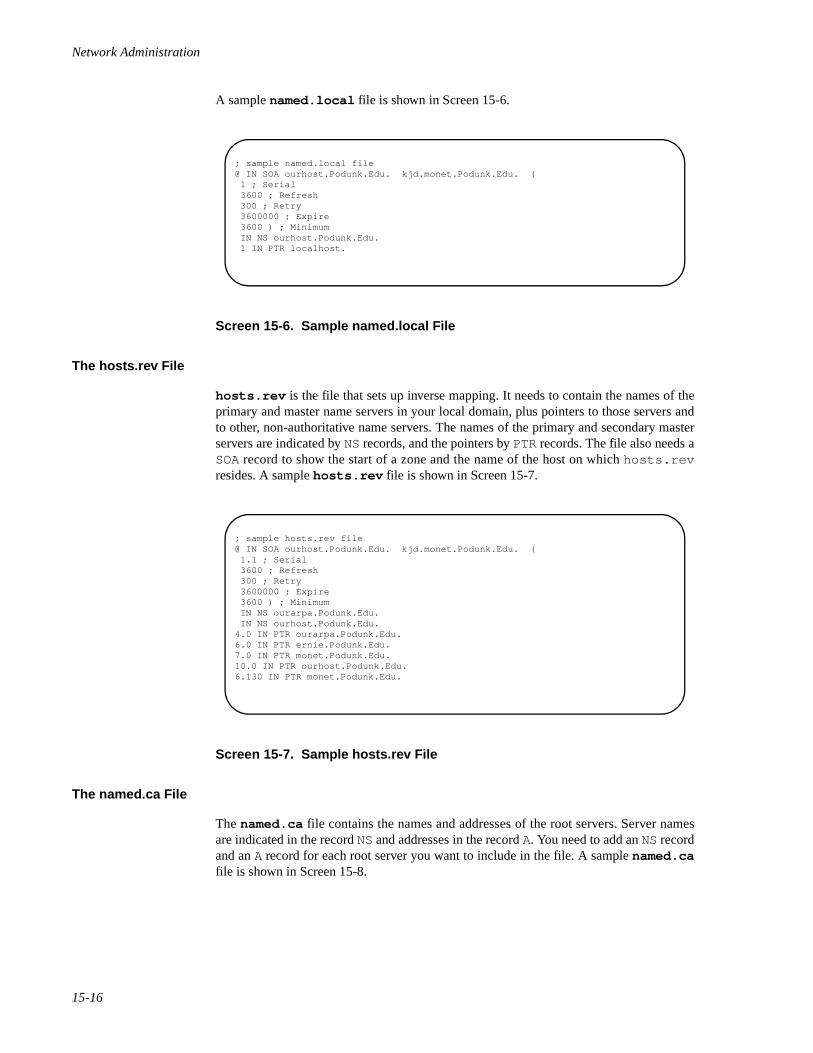
Network Administration
15-16
A sample named.local file is shown in Screen 15-6.
Screen 15-6. Sample named.local File
The hosts.rev File 15
hosts.rev is the file that sets up inverse mapping. It needs to contain the names of theprimary and master name servers in your local domain, plus pointers to those servers andto other, non-authoritative name servers. The names of the primary and secondary masterservers are indicated by NS records, and the pointers by PTR records. The file also needs aSOA record to show the start of a zone and the name of the host on which hosts.revresides. A sample hosts.rev file is shown in Screen 15-7.
Screen 15-7. Sample hosts.rev File
The named.ca File 15
The named.ca file contains the names and addresses of the root servers. Server namesare indicated in the record NS and addresses in the record A. You need to add an NS recordand an A record for each root server you want to include in the file. A sample named.cafile is shown in Screen 15-8.
; sample named.local file@ IN SOA ourhost.Podunk.Edu. kjd.monet.Podunk.Edu. ( 1 ; Serial 3600 ; Refresh 300 ; Retry 3600000 ; Expire 3600 ) ; Minimum IN NS ourhost.Podunk.Edu. 1 IN PTR localhost.
; sample hosts.rev file@ IN SOA ourhost.Podunk.Edu. kjd.monet.Podunk.Edu. ( 1.1 ; Serial 3600 ; Refresh 300 ; Retry 3600000 ; Expire 3600 ) ; Minimum IN NS ourarpa.Podunk.Edu. IN NS ourhost.Podunk.Edu.4.0 IN PTR ourarpa.Podunk.Edu.6.0 IN PTR ernie.Podunk.Edu.7.0 IN PTR monet.Podunk.Edu.10.0 IN PTR ourhost.Podunk.Edu.6.130 IN PTR monet.Podunk.Edu.
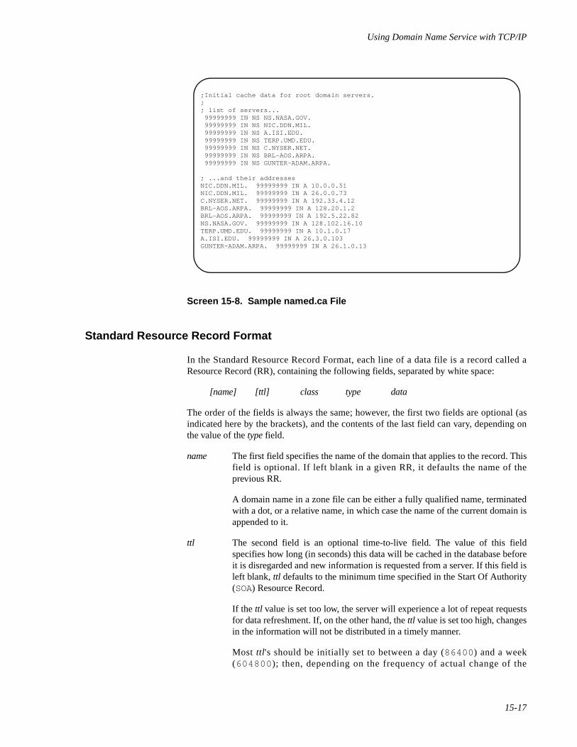
Using Domain Name Service with TCP/IP
15-17
Screen 15-8. Sample named.ca File
Standard Resource Record Format 15
In the Standard Resource Record Format, each line of a data file is a record called aResource Record (RR), containing the following fields, separated by white space:
[name] [ttl] class type data
The order of the fields is always the same; however, the first two fields are optional (asindicated here by the brackets), and the contents of the last field can vary, depending onthe value of the type field.
name The first field specifies the name of the domain that applies to the record. Thisfield is optional. If left blank in a given RR, it defaults the name of theprevious RR.
A domain name in a zone file can be either a fully qualified name, terminatedwith a dot, or a relative name, in which case the name of the current domain isappended to it.
ttl The second field is an optional time-to-live field. The value of this fieldspecifies how long (in seconds) this data will be cached in the database beforeit is disregarded and new information is requested from a server. If this field isleft blank, ttl defaults to the minimum time specified in the Start Of Authority(SOA) Resource Record.
If the ttl value is set too low, the server will experience a lot of repeat requestsfor data refreshment. If, on the other hand, the ttl value is set too high, changesin the information will not be distributed in a timely manner.
Most ttl 's should be initially set to between a day (86400 ) and a week(604800 ); then, depending on the frequency of actual change of the
;Initial cache data for root domain servers.;; list of servers... 99999999 IN NS NS.NASA.GOV. 99999999 IN NS NIC.DDN.MIL. 99999999 IN NS A.ISI.EDU. 99999999 IN NS TERP.UMD.EDU. 99999999 IN NS C.NYSER.NET. 99999999 IN NS BRL-AOS.ARPA. 99999999 IN NS GUNTER-ADAM.ARPA.
; ...and their addressesNIC.DDN.MIL. 99999999 IN A 10.0.0.51NIC.DDN.MIL. 99999999 IN A 26.0.0.73C.NYSER.NET. 99999999 IN A 192.33.4.12BRL-AOS.ARPA. 99999999 IN A 128.20.1.2BRL-AOS.ARPA. 99999999 IN A 192.5.22.82NS.NASA.GOV. 99999999 IN A 128.102.16.10TERP.UMD.EDU. 99999999 IN A 10.1.0.17A.ISI.EDU. 99999999 IN A 26.3.0.103GUNTER-ADAM.ARPA. 99999999 IN A 26.1.0.13
Network Administration
15-18
information, the ttl's should be modified to reflect that frequency. Also, if youhave some ttl's that have very high values because you know they relate to datathat rarely changes, and you know that the data is now about to change, youshould reset the ttl to a low value (3600 to 86400 ) until the change takesplace, and then change it back to the original high value.
Note that all RRs with the same name, class, and type should have the same ttlvalue.
class The third field is the record class. Only one class is currently in use: IN for theTCP/IP Internet protocol family.
type The fourth field identifies the type of the Resource Record. There are manytypes of RRs; the most commonly used types are discussed in the section“Resource Record Types” on page 15-19.
data The contents of this field depend on the type of the particular ResourceRecord.
Note that, although case is preserved in names and data fields when loaded into the nameserver, all comparisons and lookups in the name server database are case insensitive. How-ever, this situation may change in the future, and you are advised to be consistent in youruse of lowercase and uppercase.
Special Characters 15
The following characters have special meanings:
. A single free-standing dot in the name field refers to the current domain.
@ A free standing @ in the name field denotes the current origin.
.. Two free-standing dots in the name field represent the null domain name ofthe root domain.
\char Escapes the meaning of char, where char is any character other than the digits0-9. For example, you can use. (backslash-dot) to place a dot character in alabel.
\digit Escapes the meaning of the decimal number digit, where digit is a decimaloctet. The octet is assumed to be text and is not checked for special meanings.
( ) Use parentheses to group data that crosses a line. In effect, line terminationsare not recognized within parentheses.
; A semicolon starts a comment. The remainder of the line is ignored.
* An asterisk signifies wildcarding.
Most Resource Records have the current origin appended to names if they are notterminated by a dot (“.”). This is useful for appending the current domain name to the data,such as machine names, but may cause problems where you do not want this to happen. Agood rule of thumb is to use a fully qualified name ending with a dot if the name is not inthe domain for which you are creating the data file.
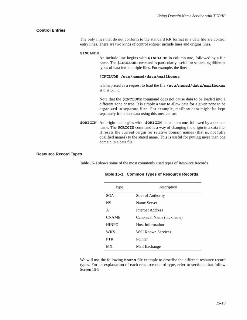
Using Domain Name Service with TCP/IP
15-19
Control Entries 15
The only lines that do not conform to the standard RR format in a data file are controlentry lines. There are two kinds of control entries: include lines and origins lines.
$INCLUDEAn include line begins with $INCLUDE in column one, followed by a filename. The $INCLUDE command is particularly useful for separating differenttypes of data into multiple files. For example, the line:
$INCLUDE /etc/named/data/mailboxes
is interpreted as a request to load the file /etc/named/data/mailboxesat that point.
Note that the $INCLUDE command does not cause data to be loaded into adifferent zone or tree. It is simply a way to allow data for a given zone to beorganized in separate files. For example, mailbox data might be keptseparately from host data using this mechanism.
$ORIGIN An origin line begins with $ORIGIN in column one, followed by a domainname. The $ORIGIN command is a way of changing the origin in a data file.It resets the current origin for relative domain names (that is, not fullyqualified names) to the stated name. This is useful for putting more than onedomain in a data file.
Resource Record Types 15
Table 15-1 shows some of the most commonly used types of Resource Records.
We will use the following hosts file example to describe the different resource recordtypes. For an explanation of each resource record type, refer to sections that followScreen 15-9.
Table 15-1. Common Types of Resource Records
Type Description
SOA Start of Authority
NS Name Server
A Internet Address
CNAME Canonical Name (nickname)
HINFO Host Information
WKS Well Known Services
PTR Pointer
MX Mail Exchange
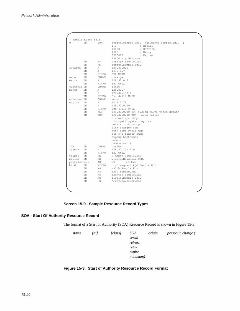
Network Administration
15-20
Screen 15-9. Sample Resource Record Types
SOA - Start Of Authority Resource Record 15
The format of a Start of Authority (SOA) Resource Record is shown in Figure 15-3.
name [ttl] [class] SOA origin person in charge (serialrefreshretryexpireminimum)
Figure 15-3. Start of Authority Resource Record Format
; sample hosts file@ IN SOA ourfox.Sample.Edu. kjd.monet.Sample.Edu. ( 1.1 ; Serial 10800 ; Refresh 1800 ; Retry 3600000 ; Expire 86400 ) ; Minimum IN NS ourarpa.Sample.Edu. IN NS ourfox.Sample.Edu.ourarpa IN A 128.32.0.4 IN A 10.0.0.7 IN HINFO 3B2 UNIXarpa IN CNAME ourarpaernie IN A 128.32.0.6 IN HINFO 3B2 UNIXourernie IN CNAME erniemonet IN A 128.32.7 IN A 128.32.130.6 IN HINFO Sun-4/110 UNIXourmonet IN CNAME monetourfox IN A 10.2.0.78 IN A 128.32.0.10 IN HINFO Sun-4/110 UNIX IN WKS 128.32.0.10 UDP syslog route timed domain IN WKS 128.32.0.10 TCP ( echo telnet discard rpc sftp uucp-path systat daytime netstat qotd nntp link chargen ftp auth time whois mtp pop rje finger smtp supdup hostnames domain nameserver )fox IN CNAME ourfoxtoybox IN A 128.32.131.119 IN HINFO 3B2 UNIXtoybox IN MX 0 monet.Sample.Edumiriam IN MB vineyd.Neighbor.COM.postmistress IN MR miriambind IN MINFO bind-request kjd.Sample.Edu. IN MG ralph.Sample.Edu. IN MG zhou.Sample.Edu. IN MG painter.Sample.Edu. IN MG riggle.Sample.Edu. IN MG terry.pa.Xerox.Com.
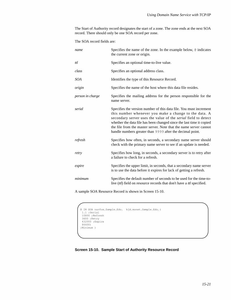
Using Domain Name Service with TCP/IP
15-21
The Start of Authority record designates the start of a zone. The zone ends at the next SOArecord. There should only be one SOA record per zone.
The SOA record fields are:
name Specifies the name of the zone. In the example below, @ indicatesthe current zone or origin.
ttl Specifies an optional time-to-live value.
class Specifies an optional address class.
SOA Identifies the type of this Resource Record.
origin Specifies the name of the host where this data file resides.
person in charge Specifies the mailing address for the person responsible for thename server.
serial Specifies the version number of this data file. You must incrementthis number whenever you make a change to the data. Asecondary server uses the value of the serial field to detectwhether the data file has been changed since the last time it copiedthe file from the master server. Note that the name server cannothandle numbers greater than 9999 after the decimal point.
refresh Specifies how often, in seconds, a secondary name server shouldcheck with the primary name server to see if an update is needed.
retry Specifies how long, in seconds, a secondary server is to retry aftera failure to check for a refresh.
expire Specifies the upper limit, in seconds, that a secondary name serveris to use the data before it expires for lack of getting a refresh.
minimum Specifies the default number of seconds to be used for the time-to-live (ttl) field on resource records that don't have a ttl specified.
A sample SOA Resource Record is shown in Screen 15-10.
Screen 15-10. Sample Start of Authority Resource Record
@ IN SOA ourfox.Sample.Edu. kjd.monet.Sample.Edu.( 1.1 ;Serial 10800 ;Refresh 3600 ;Retry 432000 ;Expire 86400);Minimum )
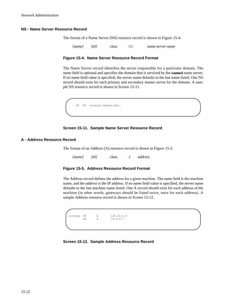
Network Administration
15-22
NS - Name Server Resource Record 15
The format of a Name Server (NS) resource record is shown in Figure 15-4.
[name] [ttl] class NS name-server name
Figure 15-4. Name Server Resource Record Format
The Name Server record identifies the server responsible for a particular domain. Thename field is optional and specifies the domain that is serviced by the named name server.If no name field value is specified, the server name defaults to the last name listed. One NSrecord should exist for each primary and secondary master server for the domain. A sam-ple NS resource record is shown in Screen 15-11.
Screen 15-11. Sample Name Server Resource Record
A - Address Resource Record 15
The format of an Address (A) resource record is shown in Figure 15-5.
[name] [ttl] class A address
Figure 15-5. Address Resource Record Format
The Address record defines the address for a given machine. The name field is the machinename, and the address is the IP address. If no name field value is specified, the server namedefaults to the last machine name listed. One A record should exist for each address of themachine (in other words, gateways should be listed twice, once for each address). Asample Address resource record is shown in Screen 15-12.
Screen 15-12. Sample Address Resource Record
IN NS ourarpa.Sample.Edu.
ourarpa IN A 128.32.0.4 IN A 10.0.0.7
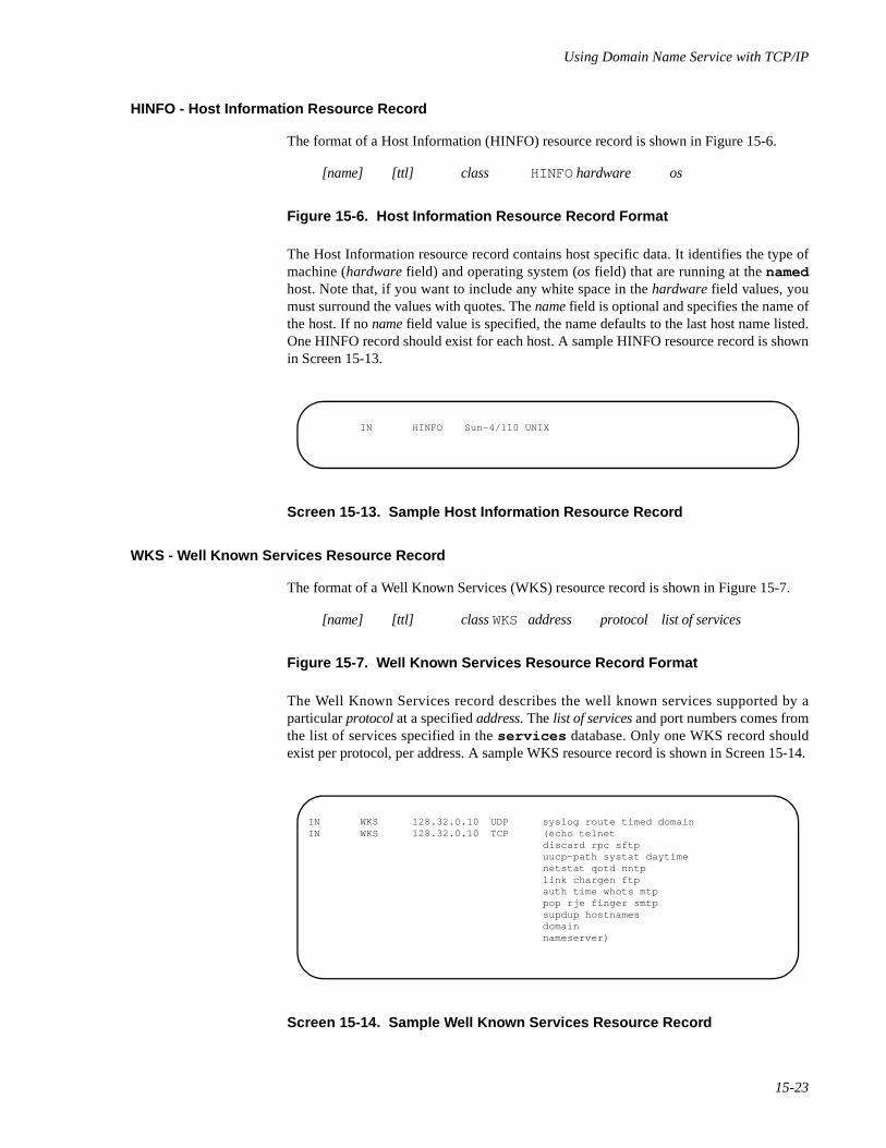
Using Domain Name Service with TCP/IP
15-23
HINFO - Host Information Resource Record 15
The format of a Host Information (HINFO) resource record is shown in Figure 15-6.
[name] [ttl] class HINFO hardware os
Figure 15-6. Host Information Resource Record Format
The Host Information resource record contains host specific data. It identifies the type ofmachine (hardware field) and operating system (os field) that are running at the namedhost. Note that, if you want to include any white space in the hardware field values, youmust surround the values with quotes. The name field is optional and specifies the name ofthe host. If no name field value is specified, the name defaults to the last host name listed.One HINFO record should exist for each host. A sample HINFO resource record is shownin Screen 15-13.
Screen 15-13. Sample Host Information Resource Record
WKS - Well Known Services Resource Record 15
The format of a Well Known Services (WKS) resource record is shown in Figure 15-7.
[name] [ttl] class WKS address protocol list of services
Figure 15-7. Well Known Services Resource Record Format
The Well Known Services record describes the well known services supported by aparticular protocol at a specified address. The list of services and port numbers comes fromthe list of services specified in the services database. Only one WKS record shouldexist per protocol, per address. A sample WKS resource record is shown in Screen 15-14.
Screen 15-14. Sample Well Known Services Resource Record
IN HINFO Sun-4/110 UNIX
IN WKS 128.32.0.10 UDP syslog route timed domainIN WKS 128.32.0.10 TCP (echo telnet
discard rpc sftpuucp-path systat daytimenetstat qotd nntplink chargen ftpauth time whots mtppop rje finger smtpsupdup hostnamesdomainnameserver)
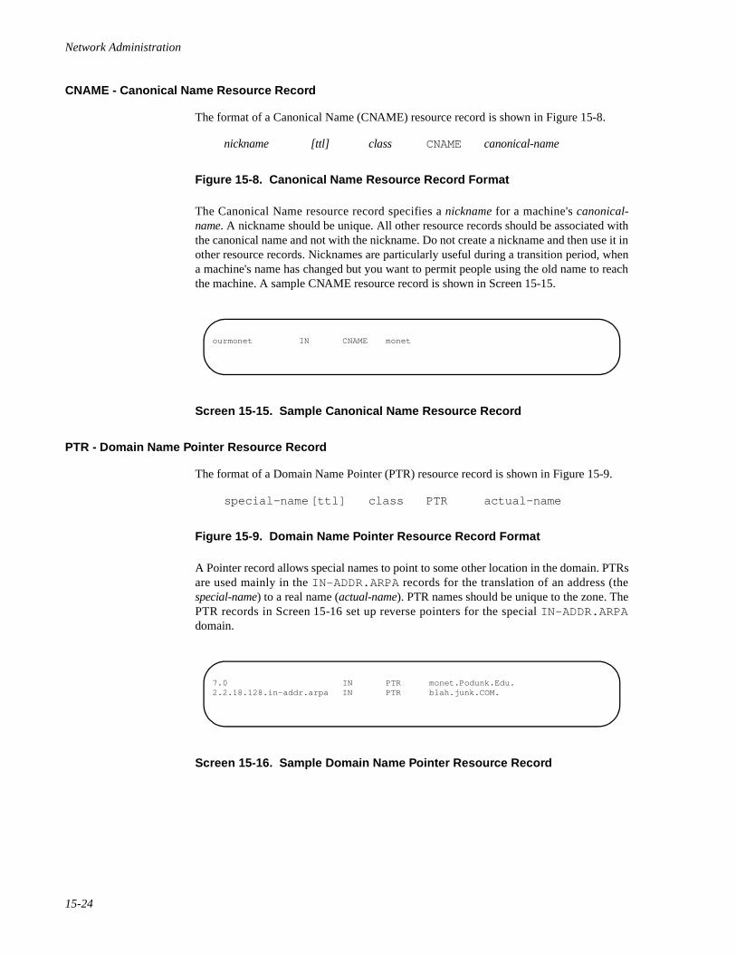
Network Administration
15-24
CNAME - Canonical Name Resource Record 15
The format of a Canonical Name (CNAME) resource record is shown in Figure 15-8.
nickname [ttl] class CNAME canonical-name
Figure 15-8. Canonical Name Resource Record Format
The Canonical Name resource record specifies a nickname for a machine's canonical-name. A nickname should be unique. All other resource records should be associated withthe canonical name and not with the nickname. Do not create a nickname and then use it inother resource records. Nicknames are particularly useful during a transition period, whena machine's name has changed but you want to permit people using the old name to reachthe machine. A sample CNAME resource record is shown in Screen 15-15.
Screen 15-15. Sample Canonical Name Resource Record
PTR - Domain Name Pointer Resource Record 15
The format of a Domain Name Pointer (PTR) resource record is shown in Figure 15-9.
special-name [ttl] class PTR actual-name
Figure 15-9. Domain Name Pointer Resource Record Format
A Pointer record allows special names to point to some other location in the domain. PTRsare used mainly in the IN-ADDR.ARPA records for the translation of an address (thespecial-name) to a real name (actual-name). PTR names should be unique to the zone. ThePTR records in Screen 15-16 set up reverse pointers for the special IN-ADDR.ARPAdomain.
Screen 15-16. Sample Domain Name Pointer Resource Record
ourmonet IN CNAME monet
7.0 IN PTR monet.Podunk.Edu.2.2.18.128.in-addr.arpa IN PTR blah.junk.COM.
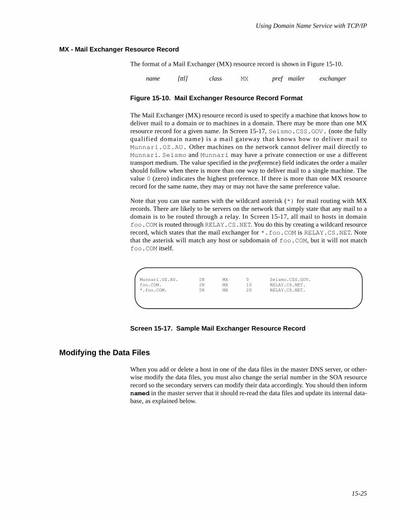
Using Domain Name Service with TCP/IP
15-25
MX - Mail Exchanger Resource Record 15
The format of a Mail Exchanger (MX) resource record is shown in Figure 15-10.
name [ttl] class MX pref mailer exchanger
Figure 15-10. Mail Exchanger Resource Record Format
The Mail Exchanger (MX) resource record is used to specify a machine that knows how todeliver mail to a domain or to machines in a domain. There may be more than one MXresource record for a given name. In Screen 15-17, Seismo.CSS.GOV. (note the fullyqualified domain name) is a mail gateway that knows how to deliver mail toMunnari.OZ.AU. Other machines on the network cannot deliver mail directly toMunnari . Seismo and Munnari may have a private connection or use a differenttransport medium. The value specified in the pref(erence) field indicates the order a mailershould follow when there is more than one way to deliver mail to a single machine. Thevalue 0 (zero) indicates the highest preference. If there is more than one MX resourcerecord for the same name, they may or may not have the same preference value.
Note that you can use names with the wildcard asterisk (*) for mail routing with MXrecords. There are likely to be servers on the network that simply state that any mail to adomain is to be routed through a relay. In Screen 15-17, all mail to hosts in domainfoo.COM is routed through RELAY.CS.NET. You do this by creating a wildcard resourcerecord, which states that the mail exchanger for *.foo.COM is RELAY.CS.NET. Notethat the asterisk will match any host or subdomain of foo.COM , but it will not matchfoo.COM itself.
Screen 15-17. Sample Mail Exchanger Resource Record
Modifying the Data Files 15
When you add or delete a host in one of the data files in the master DNS server, or other-wise modify the data files, you must also change the serial number in the SOA resourcerecord so the secondary servers can modify their data accordingly. You should then informnamed in the master server that it should re-read the data files and update its internal data-base, as explained below.
Munnari.OZ.AU. IN MX 0 Seismo.CSS.GOV.foo.COM. IN MX 10 RELAY.CS.NET.*.foo.COM. IN MX 20 RELAY.CS.NET.
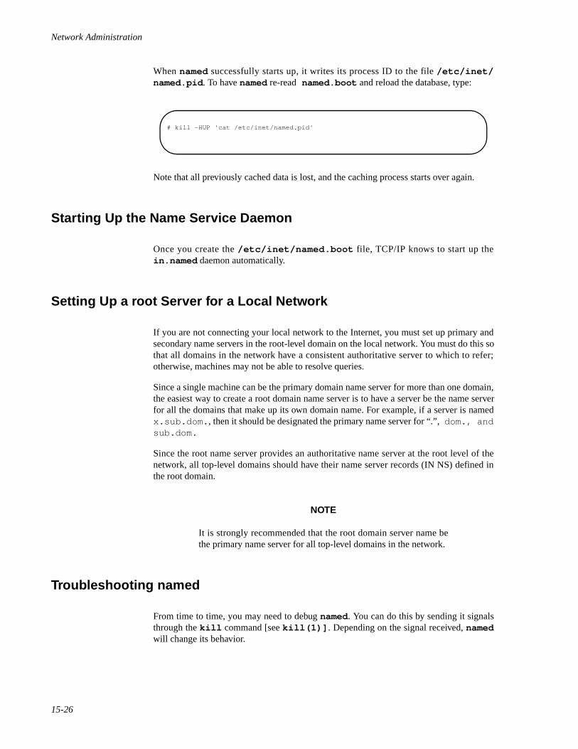
Network Administration
15-26
When named successfully starts up, it writes its process ID to the file /etc/inet/named.pid . To have named re-read named.boot and reload the database, type:
Note that all previously cached data is lost, and the caching process starts over again.
Starting Up the Name Service Daemon 15
Once you create the /etc/inet/named.boot file, TCP/IP knows to start up thein.named daemon automatically.
Setting Up a root Server for a Local Network 15
If you are not connecting your local network to the Internet, you must set up primary andsecondary name servers in the root-level domain on the local network. You must do this sothat all domains in the network have a consistent authoritative server to which to refer;otherwise, machines may not be able to resolve queries.
Since a single machine can be the primary domain name server for more than one domain,the easiest way to create a root domain name server is to have a server be the name serverfor all the domains that make up its own domain name. For example, if a server is namedx.sub.dom. , then it should be designated the primary name server for “.”, dom., andsub.dom.
Since the root name server provides an authoritative name server at the root level of thenetwork, all top-level domains should have their name server records (IN NS) defined inthe root domain.
NOTE
It is strongly recommended that the root domain server name bethe primary name server for all top-level domains in the network.
Troubleshooting named 15
From time to time, you may need to debug named. You can do this by sending it signalsthrough the kill command [see kill(1)] . Depending on the signal received, namedwill change its behavior.
# kill -HUP 'cat /etc/inet/named.pid'
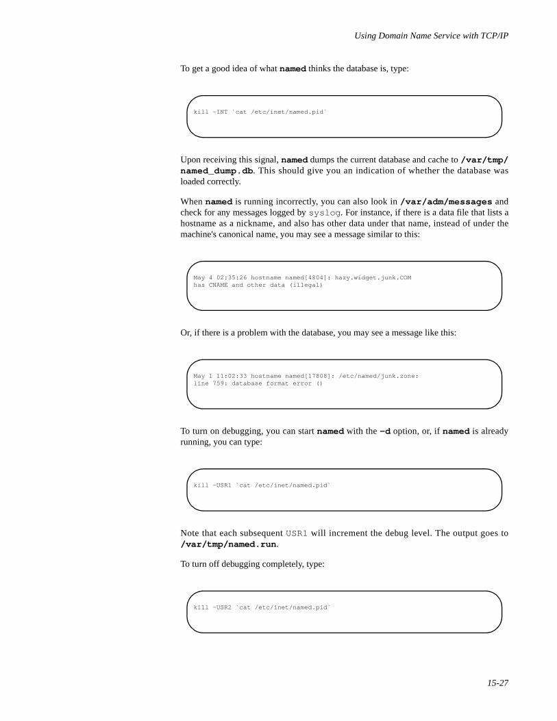
Using Domain Name Service with TCP/IP
15-27
To get a good idea of what named thinks the database is, type:
Upon receiving this signal, named dumps the current database and cache to /var/tmp/named_dump.db . This should give you an indication of whether the database wasloaded correctly.
When named is running incorrectly, you can also look in /var/adm/messages andcheck for any messages logged by syslog . For instance, if there is a data file that lists ahostname as a nickname, and also has other data under that name, instead of under themachine's canonical name, you may see a message similar to this:
Or, if there is a problem with the database, you may see a message like this:
To turn on debugging, you can start named with the -d option, or, if named is alreadyrunning, you can type:
Note that each subsequent USR1 will increment the debug level. The output goes to/var/tmp/named.run .
To turn off debugging completely, type:
kill -INT `cat /etc/inet/named.pid`
May 4 02:35:26 hostname named[4804]: hazy.widget.junk.COMhas CNAME and other data (illegal)
May 1 11:02:33 hostname named[17808]: /etc/named/junk.zone:line 759: database format error ()
kill -USR1 `cat /etc/inet/named.pid`
kill -USR2 `cat /etc/inet/named.pid`
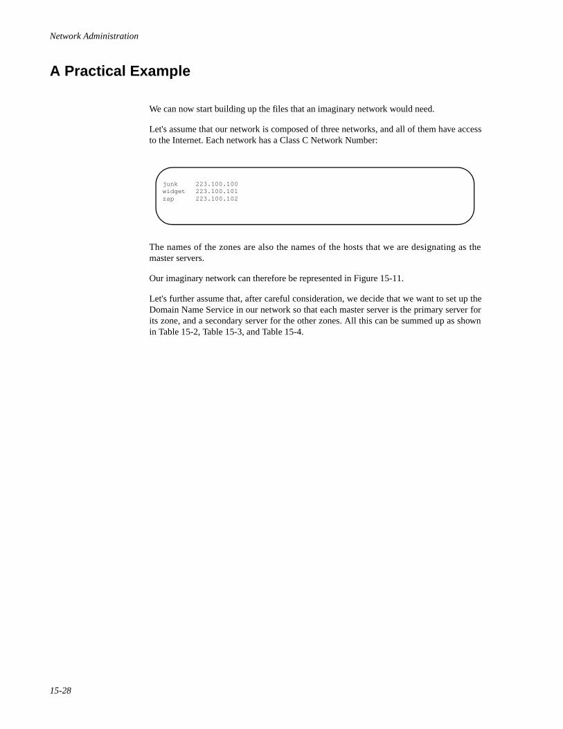
Network Administration
15-28
A Practical Example 15
We can now start building up the files that an imaginary network would need.
Let's assume that our network is composed of three networks, and all of them have accessto the Internet. Each network has a Class C Network Number:
The names of the zones are also the names of the hosts that we are designating as themaster servers.
Our imaginary network can therefore be represented in Figure 15-11.
Let's further assume that, after careful consideration, we decide that we want to set up theDomain Name Service in our network so that each master server is the primary server forits zone, and a secondary server for the other zones. All this can be summed up as shownin Table 15-2, Table 15-3, and Table 15-4.
junk 223.100.100widget 223.100.101zap 223.100.102
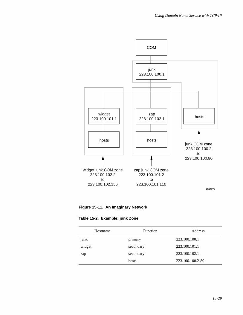
Using Domain Name Service with TCP/IP
15-29
Figure 15-11. An Imaginary Network
Table 15-2. Example: junk Zone
Hostname Function Address
junk primary 223.100.100.1
widget secondary 223.100.101.1
zap secondary 223.100.102.1
hosts 223.100.100.2-80
COM
junk223.100.100.1
161040
hosts
zap223.100.102.1
hosts
hostswidget
223.100.101.1
widget.junk.COM zone223.100.102.2
to223.100.102.156
zap.junk.COM zone223.100.101.2
to223.100.101.110
junk.COM zone223.100.100.2
to223.100.100.80
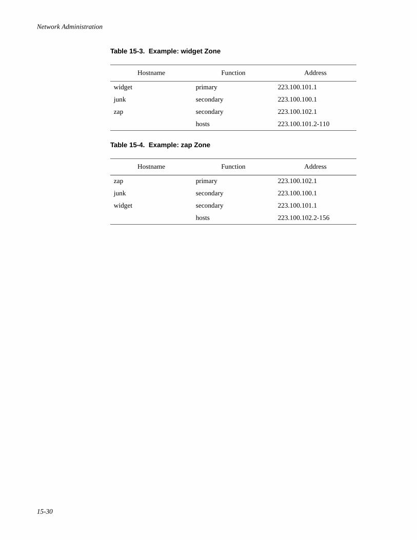
Network Administration
15-30
Table 15-3. Example: widget Zone
Hostname Function Address
widget primary 223.100.101.1
junk secondary 223.100.100.1
zap secondary 223.100.102.1
hosts 223.100.101.2-110
Table 15-4. Example: zap Zone
Hostname Function Address
zap primary 223.100.102.1
junk secondary 223.100.100.1
widget secondary 223.100.101.1
hosts 223.100.102.2-156
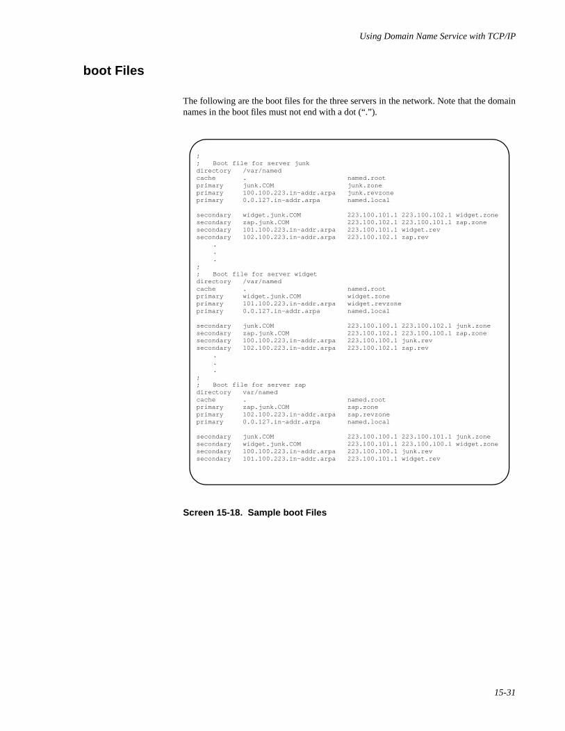
Using Domain Name Service with TCP/IP
15-31
boot Files 15
The following are the boot files for the three servers in the network. Note that the domainnames in the boot files must not end with a dot (“.”).
Screen 15-18. Sample boot Files
;; Boot file for server junkdirectory /var/namedcache . named.rootprimary junk.COM junk.zoneprimary 100.100.223.in-addr.arpa junk.revzoneprimary 0.0.127.in-addr.arpa named.local
secondary widget.junk.COM 223.100.101.1 223.100.102.1 widget.zonesecondary zap.junk.COM 223.100.102.1 223.100.101.1 zap.zonesecondary 101.100.223.in-addr.arpa 223.100.101.1 widget.revsecondary 102.100.223.in-addr.arpa 223.100.102.1 zap.rev
.
.
.;; Boot file for server widgetdirectory /var/namedcache . named.rootprimary widget.junk.COM widget.zoneprimary 101.100.223.in-addr.arpa widget.revzoneprimary 0.0.127.in-addr.arpa named.local
secondary junk.COM 223.100.100.1 223.100.102.1 junk.zonesecondary zap.junk.COM 223.100.102.1 223.100.100.1 zap.zonesecondary 100.100.223.in-addr.arpa 223.100.100.1 junk.revsecondary 102.100.223.in-addr.arpa 223.100.102.1 zap.rev
.
.
.;; Boot file for server zapdirectory var/namedcache . named.rootprimary zap.junk.COM zap.zoneprimary 102.100.223.in-addr.arpa zap.revzoneprimary 0.0.127.in-addr.arpa named.local
secondary junk.COM 223.100.100.1 223.100.101.1 junk.zonesecondary widget.junk.COM 223.100.101.1 223.100.100.1 widget.zonesecondary 100.100.223.in-addr.arpa 223.100.100.1 junk.revsecondary 101.100.223.in-addr.arpa 223.100.101.1 widget.rev

Network Administration
15-32
resolv.conf Files 15
The following are some sample resolv.conf files. Note that, if the host in question isnot running named, the local host address should not be used as a name server.
Screen 15-19. Sample resolv.conf Files
;; resolv.conf file for server junk;domain junk.COMnameserver 127.0.0.1nameserver 223.100.101.1nameserver 223.100.102.1
.
.
.;; resolv.conf file for a host in zone junk not running named;domain junk.COMnameserver 223.100.100.1nameserver 223.100.101.1nameserver 223.100.102.1
.
.
.;; resolv.conf file for a host in zone widget.junk not running named;domain widget.junk.COMnameserver 223.100.101.1nameserver 223.100.100.1nameserver 223.100.102.1
.
.
.;; resolv.conf file for a host in zone zap.junk not running named;domain zap.junk.COMnameserver 223.100.102.1nameserver 223.100.101.1nameserver 223.100.100.1
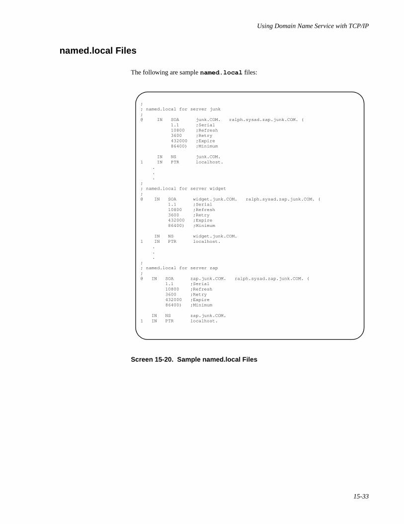
Using Domain Name Service with TCP/IP
15-33
named.local Files 15
The following are sample named.local files:
Screen 15-20. Sample named.local Files
;; named.local for server junk;@ IN SOA junk.COM. ralph.sysad.zap.junk.COM. ( 1.1 ;Serial 10800 ;Refresh 3600 ;Retry 432000 ;Expire 86400) ;Minimum
IN NS junk.COM.1 IN PTR localhost.
.
.
.;; named.local for server widget;@ IN SOA widget.junk.COM. ralph.sysad.zap.junk.COM. ( 1.1 ;Serial 10800 ;Refresh 3600 ;Retry 432000 ;Expire 86400) ;Minimum
IN NS widget.junk.COM.1 IN PTR localhost.
.
.
.;; named.local for server zap;@ IN SOA zap.junk.COM. ralph.sysad.zap.junk.COM. ( 1.1 ;Serial 10800 ;Refresh 3600 ;Retry 432000 ;Expire 86400) ;Minimum
IN NS zap.junk.COM.1 IN PTR localhost.
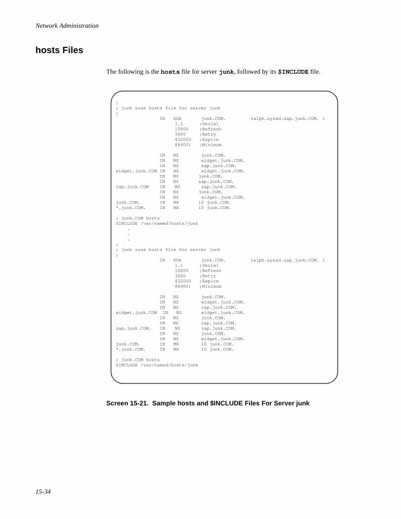
Network Administration
15-34
hosts Files 15
The following is the hosts file for server junk , followed by its $INCLUDE file.
Screen 15-21. Sample hosts and $INCLUDE Files For Server junk
;; junk zone hosts file for server junk; IN SOA junk.COM. ralph.sysad.zap.junk.COM. ( 1.1 ;Serial 10800 ;Refresh 3600 ;Retry 432000 ;Expire 86400) ;Minimum
IN NS junk.COM. IN NS widget.junk.COM. IN NS zap.junk.COM.widget.junk.COM IN NS widget.junk.COM. IN NS junk.COM. IN NS zap.junk.COM.zap.junk.COM IN NS zap.junk.COM. IN NS junk.COM. IN NS widget.junk.COM.junk.COM. IN MX 10 junk.COM.*.junk.COM. IN MX 10 junk.COM.
; junk.COM hosts$INCLUDE /var/named/hosts/junk
.
.
.;; junk zone hosts file for server junk; IN SOA junk.COM. ralph.sysad.zap.junk.COM. ( 1.1 ;Serial 10800 ;Refresh 3600 ;Retry 432000 ;Expire 86400) ;Minimum
IN NS junk.COM. IN NS widget.junk.COM. IN NS zap.junk.COM.widget.junk.COM IN NS widget.junk.COM. IN NS junk.COM. IN NS zap.junk.COM.zap.junk.COM. IN NS zap.junk.COM. IN NS junk.COM. IN NS widget.junk.COM.junk.COM. IN MX 10 junk.COM.*.junk.COM. IN MX 10 junk.COM.
; junk.COM hosts$INCLUDE /var/named/hosts/junk

Using Domain Name Service with TCP/IP
15-35
The following is the hosts file for server widget , followed by its $INCLUDE file.
Screen 15-22. Sample hosts and $INCLUDE Files For Server widget
;; widget zone hosts file for server widget; IN SOA widget.junk.COM. ralph.sysad.zap.junk.COM. (
1.1 ;Serial 10800 ;Refresh 3600 ;Retry 432000 ;Expire 86400) ;Minimum
IN NS widget.junk.COM. IN NS junk.COM. IN NS zap.junk.COM.
; junk.COM hosts$INCLUDE /var/named/hosts/widget
.
.
.; hosts in widget zone as listed in /var/named/hosts/widget
widget A 223.100.101.1 HINFO "Sun 3/180" UNIX MX 10 junk.COM.whatsit CNAME widget.junk.COMsmelly A 223.100.101.2 HINFO 3B2 UNIX MX 10 junk.COM.stinky A 223.100.101.3 HINFO 3B2 UNIX MX 10 junk.COM.dinky A 223.100.101.4 HINFO “Sun 3/160" UNIX WKS 223.100.101.4 UDP who route WKS 223.100.101.4 TCP (echo telnet discard sftp uucp-path systat daytime netstat ftp finger domain nameserver) MX 10 junk.COM.
; all other hosts follow, up to 223.100.101.110
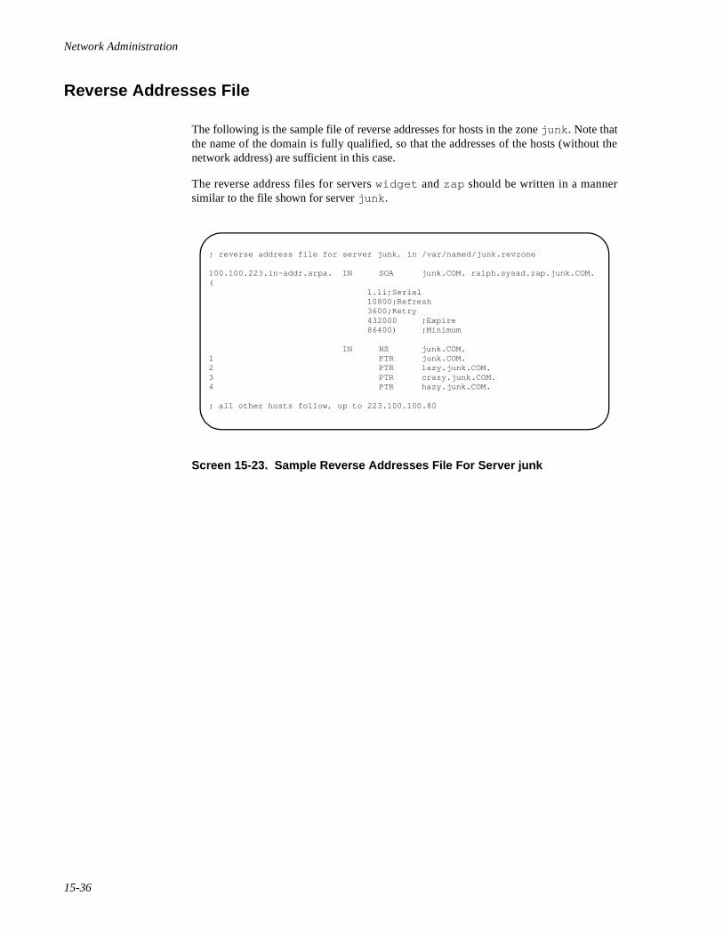
Network Administration
15-36
Reverse Addresses File 15
The following is the sample file of reverse addresses for hosts in the zone junk . Note thatthe name of the domain is fully qualified, so that the addresses of the hosts (without thenetwork address) are sufficient in this case.
The reverse address files for servers widget and zap should be written in a mannersimilar to the file shown for server junk .
Screen 15-23. Sample Reverse Addresses File For Server junk
; reverse address file for server junk, in /var/named/junk.revzone
100.100.223.in-addr.arpa. IN SOA junk.COM. ralph.sysad.zap.junk.COM. ( 1.1i;Serial 10800;Refresh 3600;Retry 432000 ;Expire 86400) ;Minimum
IN NS junk.COM.1 PTR junk.COM.2 PTR lazy.junk.COM.3 PTR crazy.junk.COM.4 PTR hazy.junk.COM.
; all other hosts follow, up to 223.100.100.80
16Troubleshooting and Tuning TCP/IP
Introduction to TCP/IP Troubleshooting and Tuning . . . . . . . . . . . . . . . . . . . . . . . . 16-1TCP/IP Troubleshooting Commands. . . . . . . . . . . . . . . . . . . . . . . . . . . . . . . . . . . . . 16-1
The ping Command . . . . . . . . . . . . . . . . . . . . . . . . . . . . . . . . . . . . . . . . . . . . . . 16-1The ifconfig Command. . . . . . . . . . . . . . . . . . . . . . . . . . . . . . . . . . . . . . . . . . . . 16-3The netstat Command. . . . . . . . . . . . . . . . . . . . . . . . . . . . . . . . . . . . . . . . . . . . . 16-4
Displaying Per Protocol Statistics . . . . . . . . . . . . . . . . . . . . . . . . . . . . . . . . 16-5Displaying Communications Controller Status . . . . . . . . . . . . . . . . . . . . . . . . . 16-6Displaying Routing Table Status . . . . . . . . . . . . . . . . . . . . . . . . . . . . . . . . . . . . 16-7
Adjusting Your Netmask to Correct Routing Problems . . . . . . . . . . . . . . . 16-7The netinfo Command . . . . . . . . . . . . . . . . . . . . . . . . . . . . . . . . . . . . . . . . . . . . 16-8
Adding a Device Entry to the netdrivers File . . . . . . . . . . . . . . . . . . . . . . . 16-8Adding Device-to-Protocol Mapping Entry to the netdrivers File . . . . . . . 16-9Listing Entries in the netdrivers File . . . . . . . . . . . . . . . . . . . . . . . . . . . . . . 16-9Removing Entries in the netdrivers File . . . . . . . . . . . . . . . . . . . . . . . . . . . 16-10Verifying the Contents of Protocol-Specific Interface File . . . . . . . . . . . . . 16-11
Running Software Checks . . . . . . . . . . . . . . . . . . . . . . . . . . . . . . . . . . . . . . . . . . . . . 16-11Troubleshooting Point-to-Point Protocol. . . . . . . . . . . . . . . . . . . . . . . . . . . . . . . . . . 16-12
Checking Modems and Cables . . . . . . . . . . . . . . . . . . . . . . . . . . . . . . . . . . . . . . 16-13Checking uucp Connection. . . . . . . . . . . . . . . . . . . . . . . . . . . . . . . . . . . . . . . . . 16-14Checking PPP Connection . . . . . . . . . . . . . . . . . . . . . . . . . . . . . . . . . . . . . . . . . 16-15
Restarting TCP/IP . . . . . . . . . . . . . . . . . . . . . . . . . . . . . . . . . . . . . . . . . . . . . . . . . . . 16-16Improving System Performance . . . . . . . . . . . . . . . . . . . . . . . . . . . . . . . . . . . . . . . . 16-17Increasing System Determinism . . . . . . . . . . . . . . . . . . . . . . . . . . . . . . . . . . . . . . . . 16-18Tuning TCP/IP Kernel Parameters . . . . . . . . . . . . . . . . . . . . . . . . . . . . . . . . . . . . . . 16-18
asyhdlc Tunable Parameters . . . . . . . . . . . . . . . . . . . . . . . . . . . . . . . . . . . . . . . . 16-19asyhdlc stune Parameters . . . . . . . . . . . . . . . . . . . . . . . . . . . . . . . . . . . . . . 16-19
ip Tunable Parameters . . . . . . . . . . . . . . . . . . . . . . . . . . . . . . . . . . . . . . . . . . . . 16-19ip stune Parameters . . . . . . . . . . . . . . . . . . . . . . . . . . . . . . . . . . . . . . . . . . . 16-20ip ndd Parameters . . . . . . . . . . . . . . . . . . . . . . . . . . . . . . . . . . . . . . . . . . . . 16-20
ppp Tunable Parameters . . . . . . . . . . . . . . . . . . . . . . . . . . . . . . . . . . . . . . . . . . . 16-20ppp Space.c Parameters. . . . . . . . . . . . . . . . . . . . . . . . . . . . . . . . . . . . . . . . 16-20
arp, rawip, tcp, and udp Tunable Parameters . . . . . . . . . . . . . . . . . . . . . . . . . . . 16-20Logging Network Problems. . . . . . . . . . . . . . . . . . . . . . . . . . . . . . . . . . . . . . . . . . . . 16-21

Network Administration
16-1
16Chapter 16Troubleshooting and Tuning TCP/IP
161616
Introduction to TCP/IP Troubleshooting and Tuning 16
TCP/IP has several facilities you can use to troubleshoot problems and maximize systemperformance. These facilities include special TCP/IP commands and TCP/IP tunableparameters.
TCP/IP Troubleshooting Commands 16
TCP/IP includes several commands that help you troubleshoot, should you have problemswith the network. These commands are:
• ping
• ifconfig
• netstat
The following sections describe these commands and give suggestions for using them.
The ping Command 16
The ping command offers the simplest way to find out if a host on your network isresponding to TCP/IP packets or not. The basic syntax of ping is as follows:
/usr/sbin/ping host [ timeout]
where host is the hostname of the machine in question. The optional timeout argumentindicates the time, in seconds, for ping to keep trying to reach the machine (the default is20 seconds). See ping(1M) for further information on the ping command.
When you run ping , the ICMP protocol sends a datagram to the host you specify, askingfor a response. (Remember that ICMP is the protocol responsible for error handling on aTCP/IP network.)
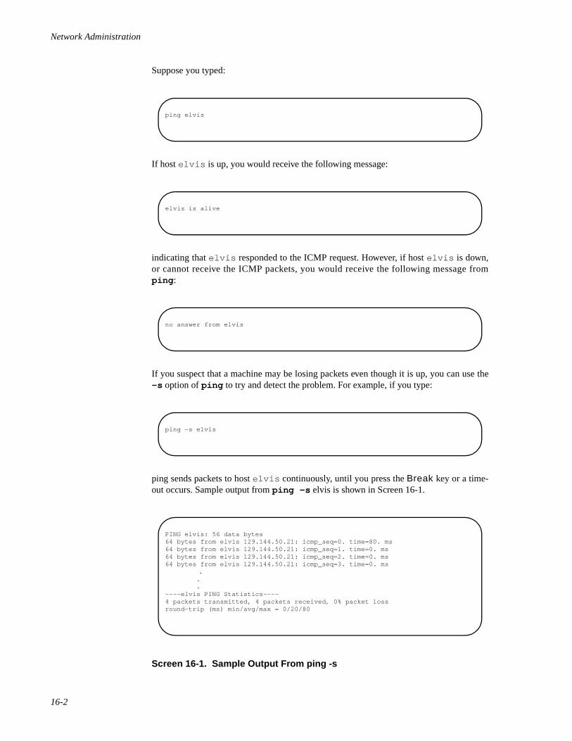
Network Administration
16-2
Suppose you typed:
If host elvis is up, you would receive the following message:
indicating that elvis responded to the ICMP request. However, if host elvis is down,or cannot receive the ICMP packets, you would receive the following message fromping :
If you suspect that a machine may be losing packets even though it is up, you can use the-s option of ping to try and detect the problem. For example, if you type:
ping sends packets to host elvis continuously, until you press the Break key or a time-out occurs. Sample output from ping -s elvis is shown in Screen 16-1.
Screen 16-1. Sample Output From ping -s
ping elvis
elvis is alive
no answer from elvis
ping -s elvis
PING elvis: 56 data bytes64 bytes from elvis 129.144.50.21: icmp_seq=0. time=80. ms64 bytes from elvis 129.144.50.21: icmp_seq=1. time=0. ms64 bytes from elvis 129.144.50.21: icmp_seq=2. time=0. ms64 bytes from elvis 129.144.50.21: icmp_seq=3. time=0. ms
. . .----elvis PING Statistics----4 packets transmitted, 4 packets received, 0% packet lossround-trip (ms) min/avg/max = 0/20/80
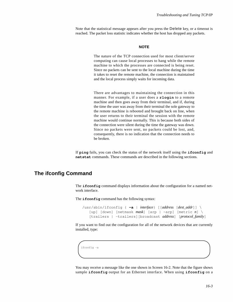
Troubleshooting and Tuning TCP/IP
16-3
Note that the statistical message appears after you press the Delete key, or a timeout isreached. The packet loss statistic indicates whether the host has dropped any packets.
NOTE
The nature of the TCP connection used for most client/servercomputing can cause local processes to hang while the remotemachine to which the processes are connected is being reset.Since no packets can be sent to the local machine during the timeit takes to reset the remote machine, the connection is maintainedand the local process simply waits for incoming data.
There are advantages to maintaining the connection in thismanner. For example, if a user does a rlogin to a remotemachine and then goes away from their terminal, and if, duringthe time the user was away from their terminal the sole gateway tothe remote machine is rebooted and brought back on line, whenthe user returns to their terminal the session with the remotemachine would continue normally. This is because both sides ofthe connection were silent during the time the gateway was down.Since no packets were sent, no packets could be lost, and,consequently, there is no indication that the connection needs tobe broken.
If ping fails, you can check the status of the network itself using the ifconfig andnetstat commands. These commands are described in the following sections.
The ifconfig Command 16
The ifconfig command displays information about the configuration for a named net-work interface.
The ifconfig command has the following syntax:
/usr/sbin/ifconfig { -a | interface} [[ address [ dest_addr]] \ [up] [down] [netmask mask] [arp | -arp] [metric n] \ [trailers | -trailers][broadcast address] [ protocol_family]
If you want to find out the configuration for all of the network devices that are currentlyinstalled, type:
You may receive a message like the one shown in Screen 16-2. Note that the figure showssample ifconfig output for an Ethernet interface. When using ifconfig on a
ifconfig -a
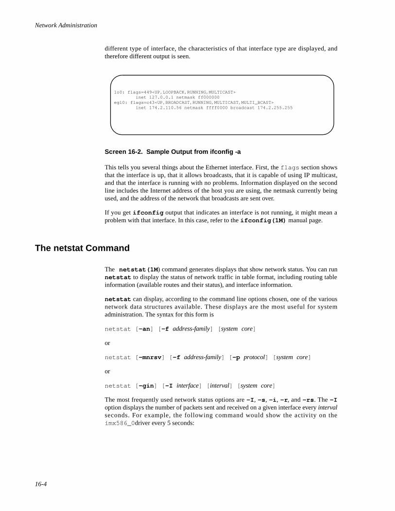
Network Administration
16-4
different type of interface, the characteristics of that interface type are displayed, andtherefore different output is seen.
Screen 16-2. Sample Output from ifconfig -a
This tells you several things about the Ethernet interface. First, the flags section showsthat the interface is up, that it allows broadcasts, that it is capable of using IP multicast,and that the interface is running with no problems. Information displayed on the secondline includes the Internet address of the host you are using, the netmask currently beingused, and the address of the network that broadcasts are sent over.
If you get ifconfig output that indicates an interface is not running, it might mean aproblem with that interface. In this case, refer to the ifconfig(1M) manual page.
The netstat Command 16
The netstat(1M ) command generates displays that show network status. You can runnetstat to display the status of network traffic in table format, including routing tableinformation (available routes and their status), and interface information.
netstat can display, according to the command line options chosen, one of the variousnetwork data structures available. These displays are the most useful for systemadministration. The syntax for this form is
netstat [ -an ] [ -f address-family] [ system core]
or
netstat [ -mnrsv ] [ -f address-family] [ -p protocol] [ system core]
or
netstat [ -gin ] [ -I interface] [ interval] [ system core]
The most frequently used network status options are -I , -s , -i , -r , and -rs . The -Ioption displays the number of packets sent and received on a given interface every intervalseconds. For example, the following command would show the activity on theimx586_0 driver every 5 seconds:
lo0: flags=449<UP,LOOPBACK,RUNNING,MULTICAST> inet 127.0.0.1 netmask ff000000egl0: flags=c43<UP,BROADCAST,RUNNING,MULTICAST,MULTI_BCAST> inet 174.2.110.56 netmask ffff0000 broadcast 174.2.255.255
Troubleshooting and Tuning TCP/IP
16-5
The other netstat network status options are described in the following sections.
Displaying Per Protocol Statistics 16
The -s option displays per-protocol statistics for the UDP, TCP, ICMP, and IP protocols.To display statistics for all protocols, type:
To display statistics for a particular protocol, type:
For example, typing:
produces statistics that look like the following:
netstat -I ie0 5
netstat -s
netstat -p protocol
netstat -p ip
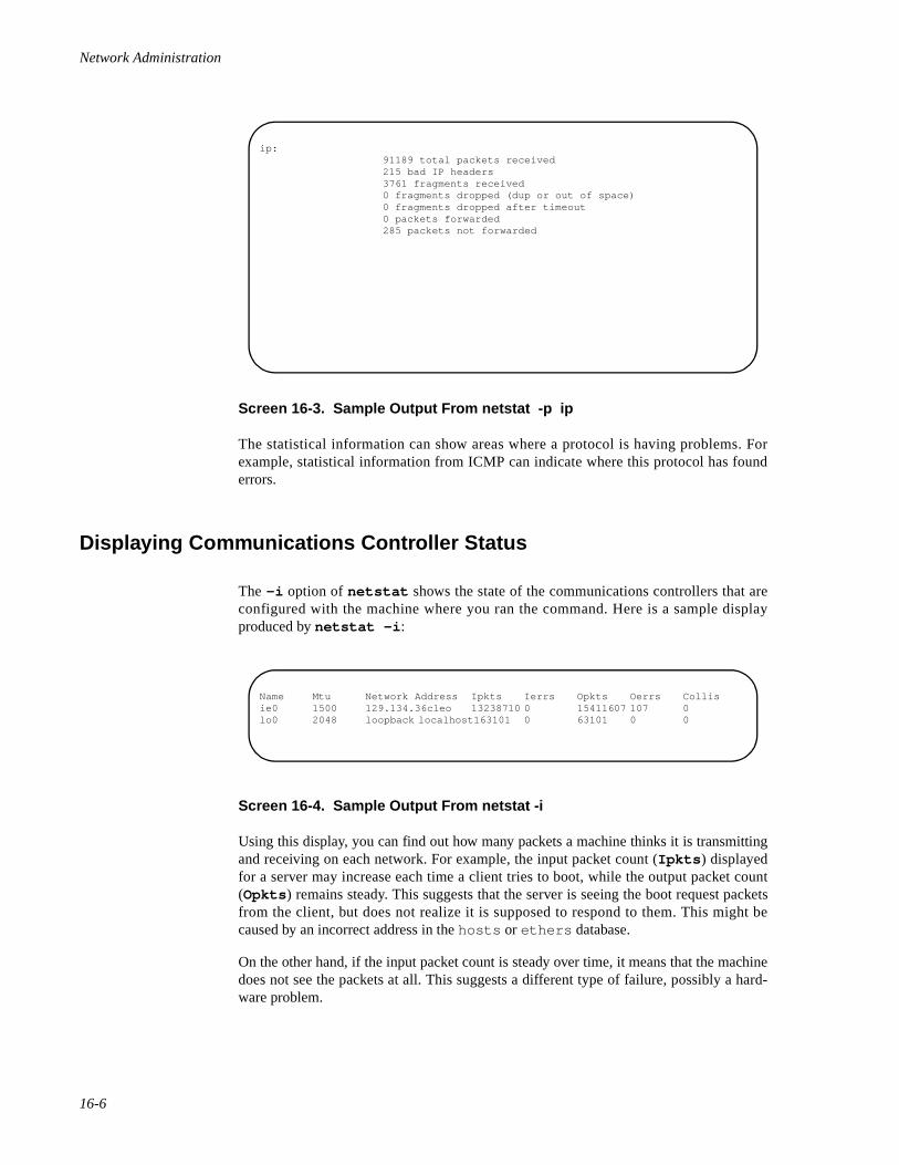
Network Administration
16-6
Screen 16-3. Sample Output From netstat -p ip
The statistical information can show areas where a protocol is having problems. Forexample, statistical information from ICMP can indicate where this protocol has founderrors.
Displaying Communications Controller Status 16
The -i option of netstat shows the state of the communications controllers that areconfigured with the machine where you ran the command. Here is a sample displayproduced by netstat -i :
Screen 16-4. Sample Output From netstat -i
Using this display, you can find out how many packets a machine thinks it is transmittingand receiving on each network. For example, the input packet count (Ipkts ) displayedfor a server may increase each time a client tries to boot, while the output packet count(Opkts ) remains steady. This suggests that the server is seeing the boot request packetsfrom the client, but does not realize it is supposed to respond to them. This might becaused by an incorrect address in the hosts or ethers database.
On the other hand, if the input packet count is steady over time, it means that the machinedoes not see the packets at all. This suggests a different type of failure, possibly a hard-ware problem.
ip: 91189 total packets received 215 bad IP headers 3761 fragments received 0 fragments dropped (dup or out of space) 0 fragments dropped after timeout 0 packets forwarded 285 packets not forwarded
Name Mtu Network Address Ipkts Ierrs Opkts Oerrs Collisie0 1500 129.134.36cleo 13238710 0 15411607 107 0lo0 2048 loopback localhost163101 0 63101 0 0
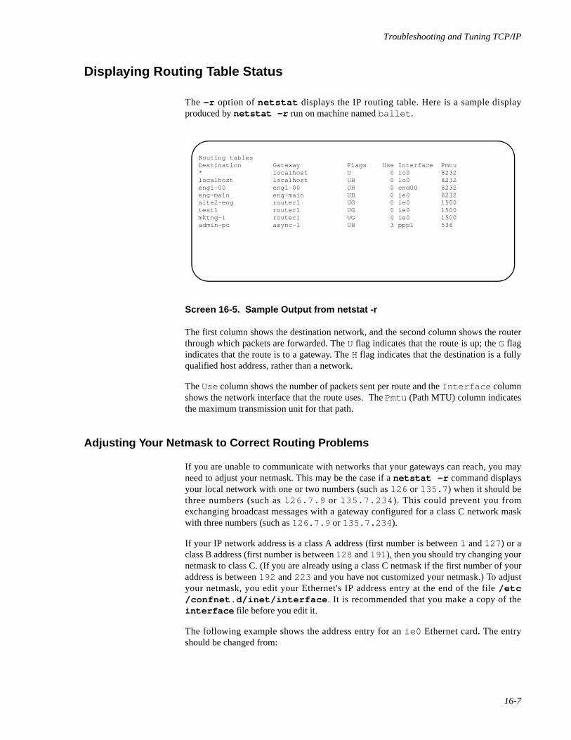
Troubleshooting and Tuning TCP/IP
16-7
Displaying Routing Table Status 16
The -r option of netstat displays the IP routing table. Here is a sample displayproduced by netstat -r run on machine named ballet .
Screen 16-5. Sample Output from netstat -r
The first column shows the destination network, and the second column shows the routerthrough which packets are forwarded. The U flag indicates that the route is up; the G flagindicates that the route is to a gateway. The H flag indicates that the destination is a fullyqualified host address, rather than a network.
The Use column shows the number of packets sent per route and the Interface columnshows the network interface that the route uses. The Pmtu (Path MTU) column indicatesthe maximum transmission unit for that path.
Adjusting Your Netmask to Correct Routing Problems 16
If you are unable to communicate with networks that your gateways can reach, you mayneed to adjust your netmask. This may be the case if a netstat -r command displaysyour local network with one or two numbers (such as 126 or 135.7 ) when it should bethree numbers (such as 126.7.9 or 135.7.234 ). This could prevent you fromexchanging broadcast messages with a gateway configured for a class C network maskwith three numbers (such as 126.7.9 or 135.7.234 ).
If your IP network address is a class A address (first number is between 1 and 127 ) or aclass B address (first number is between 128 and 191 ), then you should try changing yournetmask to class C. (If you are already using a class C netmask if the first number of youraddress is between 192 and 223 and you have not customized your netmask.) To adjustyour netmask, you edit your Ethernet's IP address entry at the end of the file /etc/confnet.d/inet/interface . It is recommended that you make a copy of theinterface file before you edit it.
The following example shows the address entry for an ie0 Ethernet card. The entryshould be changed from:
Routing tablesDestination Gateway Flags Use Interface Pmtu* localhost U 0 lo0 8232localhost localhost UH 0 lo0 8232eng1-00 eng1-00 UH 0 cnd00 8232eng-main eng-main UH 0 ie0 8232site2-eng router1 UG 0 ie0 1500test1 router1 UG 0 ie0 1500mktng-1 router1 UG 0 ie0 1500admin-pc async-1 UH 3 ppp1 536
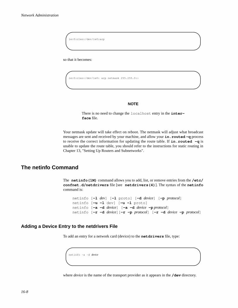
Network Administration
16-8
so that it becomes:
NOTE
There is no need to change the localhost entry in the inter-face file.
Your netmask update will take effect on reboot. The netmask will adjust what broadcastmessages are sent and received by your machine, and allow your in.routed -q processto receive the correct information for updating the route table. If in.routed -q isunable to update the route table, you should refer to the instructions for static routing inChapter 13, "Setting Up Routers and Subnetworks".
The netinfo Command 16
The netinfo(1M) command allows you to add, list, or remove entries from the /etc/confnet.d/netdrivers file [see netdrivers(4) ]. The syntax of the netinfocommand is:
netinfo [ -l dev] [ -l proto] [ -d device] [ -p protocol]netinfo [ -u -l dev] [ -u -l proto]netinfo [ -a -d device] [ -a -d device -p protocol]netinfo [ -r -d device][ -r -p protocol] [ -r -d device -p protocol]
Adding a Device Entry to the netdrivers File 16
To add an entry for a network card (device) to the netdrivers file, type:
where device is the name of the transport provider as it appears in the /dev directory.
ie:0:cleo:/dev/ie0:arp
ie:0:cleo:/dev/ie0: arp netmask 255.255.0::
netinfo -a -d device
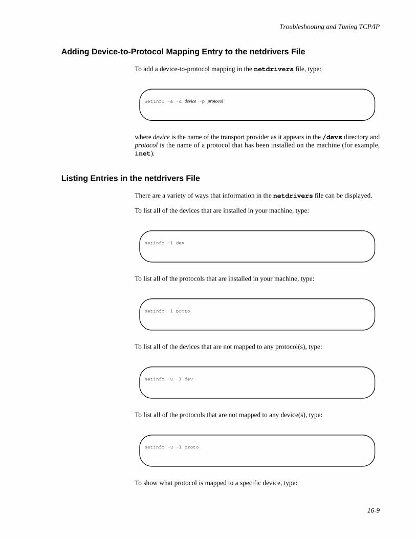
Troubleshooting and Tuning TCP/IP
16-9
Adding Device-to-Protocol Mapping Entry to the netdrivers File 16
To add a device-to-protocol mapping in the netdrivers file, type:
where device is the name of the transport provider as it appears in the /devs directory andprotocol is the name of a protocol that has been installed on the machine (for example,inet ).
Listing Entries in the netdrivers File 16
There are a variety of ways that information in the netdrivers file can be displayed.
To list all of the devices that are installed in your machine, type:
To list all of the protocols that are installed in your machine, type:
To list all of the devices that are not mapped to any protocol(s), type:
To list all of the protocols that are not mapped to any device(s), type:
To show what protocol is mapped to a specific device, type:
netinfo -a -d device -p protocol
netinfo -l dev
netinfo -l proto
netinfo -u -l dev
netinfo -u -l proto
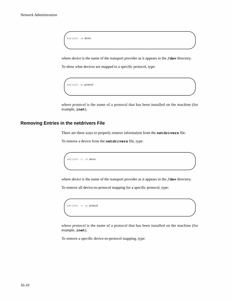
Network Administration
16-10
where device is the name of the transport provider as it appears in the /dev directory.
To show what devices are mapped to a specific protocol, type:
where protocol is the name of a protocol that has been installed on the machine (forexample, inet ).
Removing Entries in the netdrivers File 16
There are three ways to properly remove information from the netdrivers file.
To remove a device from the netdrivers file, type:
where device is the name of the transport provider as it appears in the /dev directory.
To remove all device-to-protocol mapping for a specific protocol, type:
where protocol is the name of a protocol that has been installed on the machine (forexample, inet ).
To remove a specific device-to-protocol mapping, type:
netinfo -d device
netinfo -p protocol
netinfo -r -d device
netinfo -r -p protocol
Troubleshooting and Tuning TCP/IP
16-11
where device is the name of the transport provider as it appears in the /dev directory andprotocol is the name of a protocol that has been installed on the machine (for example,inet ).
Verifying the Contents of Protocol-Specific Interface File 16
Since inet is the only networking protocol supported under MP, the only interface fileneeding verification is in /etc/confnet.d/inet/interface .
For more information on the /etc/confnet.d/inet/interface file, see the INET-specific interface(4) manual page.
Running Software Checks 16
If there is trouble on the network, here are some actions you can take to diagnose and fixsoftware-related problems.
1. Use the netstat command to determine network status as describedpreviously.
2. Check the /etc/hosts file to make sure that the entries are correct andup to date.
3. Check the accuracy of the line(s) in the /etc/confnet.d/inet/interface file. See INET-specific interface(4) for the format of anentry in the interface file.
4. Try to rlogin to yourself by entering one of the following commands:
• rlogin `uname -n`
• rlogin localhost
If the first bullet item is successful, then you are able to send TCP packetsand process them on the `uname -n` machine. The `uname -n` systemname is usually associated with first network device installed in themachine. If the first bullet item is successful and other machines cannotrlogin into the machine you are troubleshooting, then check the hard-ware and cables associated with the first network device.
If the second bullet item is successful and the first is not, verify thelocalhost entry in the /etc/confnet.d/inet/interface file.Some configuration files are date dependent. If you have restored some oldfiles or updated a number of files manually, type:
netinfo -r -d device -p protocol
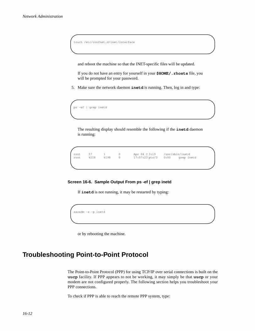
Network Administration
16-12
and reboot the machine so that the INET-specific files will be updated.
If you do not have an entry for yourself in your $HOME/.rhosts file, youwill be prompted for your password.
5. Make sure the network daemon inetd is running. Then, log in and type:
The resulting display should resemble the following if the inetd daemonis running:
Screen 16-6. Sample Output From ps -ef | grep inetd
If inetd is not running, it may be restarted by typing:
or by rebooting the machine.
Troubleshooting Point-to-Point Protocol 16
The Point-to-Point Protocol (PPP) for using TCP/IP over serial connections is built on theuucp facility. If PPP appears to not be working, it may simply be that uucp or yourmodem are not configured properly. The following section helps you troubleshoot yourPPP connections.
To check if PPP is able to reach the remote PPP system, type:
touch /etc/confnet.d/inet/interface
ps -ef | grep inetd
root 57 1 0 Apr 04 ? 3:19 /usr/sbin/inetdroot 4218 4198 0 17:57:23 pts/3 0:00 grep inetd
sacadm -s -p inetd
Troubleshooting and Tuning TCP/IP
16-13
where remote is replaced by the TCP/IP name of the remote PPP system. If you do notreceive an acknowledgment that the remote PPP system is alive, check that you cancontact the remote system using uucp .
To check your uucp connection to the remote system, type:
where remote is the uucp name (in the /etc/uucp/Systems file) of the remotesystem. If you can establish a connection with the remote system, recheck your PPPconfiguration. If you cannot establish a connection, check the connection from the bottomup as described in the following paragraphs.
CAUTION
The cu command picks up the current stty settings when it triesto establish a connection with the remote system. This can causeundesirable results, such as changing your modem settingsinvisibly.
Checking Modems and Cables 16
Check the cables and modem settings you are using. If you are directly connecting twosystems, make sure the cable is a null-modem cable. If you are using modems to connect,make sure that modem settings match on the remote and local sides. Line speed and parityare two important settings.
If you think you need to change modem settings, use the cu command to directly call themodem attached to your computer. The procedure for changing your modem settings iscontained in the PPP section of the chapter “Setting Up TCP/IP.”
Before you use the cu command to connect to the modem, check the stty settings bytyping:
ping -s remote
cu remote
Network Administration
16-14
Once you connect to your local modem, list out the entire profile of the modem (ifpossible) and compare the settings.
If you feel the modems are set up correctly, try dialing directly across the connection. On aHayes-compatible modem, type ATDT and the phone number to place the call.
Checking uucp Connection 16
If the modem or direct connection seem to be working properly, try calling across theconnection again with the cu command. Running cu from different shells (the console, aTerminal window, or a remote login) can sometimes cause cu to fail, and possibly resetthe modem settings.
If the cu works, but PPP still doesn't work, there may be a problem in the chat script youcreated for the remote system in the /etc/uucp/Systems file. This script must notonly connect to the remote system, but it must also login as the PPP user. To check thescript, type:
where remote is replaced by the remote uucp system name in your /etc/uucp/Systems file. This will actually connect to the remote system and log in based on thechat script in the Systems file.
If the remote system is very slow, it is possible that PPP could time out before the connec-tion is completed. To avoid this, make sure the last part of the chat script matches somestring that the remote system sends you after login is complete. For example, in the PPPprocedure in the chapter “Setting Up TCP/IP” we recommend using the string opyrightas the last part of the chat script. After logging into the remote system, the dialfunction (see the dial(3N) manual page) passes the connection to PPP after it sees theCopyright message after login.
If the full connection and login chat script seems to work once, but then not work, goback and check your modem settings again and see if uucp reset them automaticallyagain. You may have to change them back again.
stty -a
/usr/lib/uucp/Uutry -r remote
Troubleshooting and Tuning TCP/IP
16-15
Checking PPP Connection 16
Once you are convinced that the uucp connection is working properly, try running ping-s remote to the remote PPP system again. If the call is going through, but the ping doesnot show packets received from the remote system, run the ppstat command.
The following are some of the errors that can occur with PPP that can be determined byrunning pppstat :
• Password authentication failure. If this occurs, make sure the passwordsmatch on the local and remote systems.
• Received a packet with bad FCS. You received a packet with a checksumerror. Try turning on hardware flow control on the connection. This mayrequire requesting hardware flow control on one of the modem settings andusing the hardware flow control device on your uucp connection. (Forexample, use /dev/tty00h instead of /dev/tty00 for yourconnection.)
• Received packets with bad id field or loopback packets. Make sure thecable connection is correct. You may be receiving your own packets back,which could indicate that some of the pin connections on your cable are notcorrect.
• Received state table errors. This would indicate a PPP connection to aremote system that has a different and incompatible PPP implementation.
Another way to check the PPP connection is by typing:
Look for incoming and outgoing packet errors for your PPP connection in the netstatoutput. If there are no packets, the connection is not working. If there are lots of errors,you may simply have a dirty line.
Finally, you may want to check that the PPP interface was set up correctly in the firstplace. To do this, type:
The PPP interface should appear as one of the interfaces and should be listed as UP. If thePPP interface is not there, you may need to add it by typing:
netstat -i
ifconfig -a
Network Administration
16-16
If the PPP interface is there, but not up, type:
This would make the first PPP interface on your computer (ppp0 ) available for use.
Restarting TCP/IP 16
If you are a privileged user and need to stop and restart TCP/IP, use the followingprocedure.
CAUTION
The following should only be done if you are willing to lose allcurrent network connections. You should only stop TCP whendebugging the interface or other boot sensitive files. Make surethat any remotely mounted or shared resources are not in usewhen you do the following procedure.
1. To stop TCP/IP, do the following:
• If you are running NFS, stop NFS by typing:
• Stop other processes using TCP/IP.
• Kill inetd and the TCP/IP listener by typing the commands:
configure -i.
ifconfig ppp0 up
sh -x /etc/init.d/nfs stop
Troubleshooting and Tuning TCP/IP
16-17
• Shut down and unlink STREAMS by typing:
2. To restart TCP/IP, do the following:
• Start and link the STREAMS by typing:
• Restart inetd and the listener by typing the commands:
• If you use NFS on your system, restart NFS typing:
Improving System Performance 16
If you are having performance problems, your problems may be the result of running thedaemons routed and rwhod .
The system status daemon rwhod is not run by default, because it can seriously degradesystem and network performance. You are strongly advised not to run it.
sacadm -k -p inetd sacadm -k -p tcp
sh -x /etc/init.d/inetinit stop
sh +x /etc/init.d/inetinit start
sacadm -s -p inetd sacadm -s -p tcp
sh -x /etc/init.d/nfs start
Network Administration
16-18
The routing daemon routed is run by default. If your machine has limited memory andthere are no routers on your network, then you do not need to run routed . You candisable routed by commenting out (inserting the “#” character) the line:
in the start-up script /etc/inet/rc.inet .
If your machine has limited memory and only one router in your network, then you canrun routed only on the router, and disable it on all other machines.
For more information about configuring a router, see Chapter 13, "Setting Up Routers andSubnetworks".
Increasing System Determinism 16
Concurrent’s TCP/IP implementation is STREAMS based. As such, TCP/IP STREAMSservice procedures may usually be executed on any CPU in the system. These STREAMSservice procedure executions can cause a reduction in the determinism of applicationswhen and if those applications are preempted by the kernel to execute queued STREAM’sservice procedures.
On systems that are configured for real-time applications, it may be desirable to restrictthe CPUs that may execute STREAMS service procedures. It may also be necessary toenable a kernel feature that provides a STREAMS service procedure CPU bias mask on aper-STREAM basis in order to provide even greater control over which CPU(s) executeeach STREAM’s service procedures. For more information on this subject, see the section“Controlling STREAMS Scheduling” in the PowerMAX OS Real-Time Guide (Pubs No.0890466).
Tuning TCP/IP Kernel Parameters 16
To maximize your system resources, you can modify three types of TCP/IP tunableparameters:
• General-purpose TCP/IP parameters are located in the /etc/conf/cf.d/stune file.
• Tunable parameters associated with allocating and initializing configura-tion-dependent data structures for the individual TCP/IP kernel modulesare located in Space.c files in subdirectories of /etc/conf/pack.d .
• Tunable parameters used by ARP, IP, RAWIP, UDP and TCP accessible viathe ndd program.
/usr/sbin/in.routed -q
Troubleshooting and Tuning TCP/IP
16-19
TCP/IP tunable parameters in the stune file should not be edited directly. To change thevalue of a parameter in the stune file, you should use the config(1M) program. Formore information see the chapter “Tunable Parameters” in the guide SystemAdministration. You may also want to refer to the stune(4) manual page.
TCP/IP tunable parameters in Space.c files may be edited directly. The parameters withupper case names are defined constants; those with lower case names are variables. Tochange a defined constant, you can change the constant itself. To change a variable, youchange the value the variable is set to. For information about the Space.c file, see theSpace.c(4) manual page.
TCP/IP tunable parameters can be set and retrieved using a set of functions called NamedDispatch. An interface to the Named Dispatch is the ndd program.
The ndd program provides a simple command line interface to the Named Dispatch facil-ity. The program accepts arguments from the command line or may be run interactively.The general form of the command line is:
ndd [-set| -get] device_name ndd_name [value]
The tunable parameters accessed by the ndd command are for advanced users. Please seethe TCP/IP Program Interfaces Guide (0890468) for more information.
Note that once you modify a TCP/IP tunable parameter in the stune file or in aSpace.c file, you need to rebuild the kernel and then reboot the system so that yourchanges will take effect. See the idbuild(1M) manual page for more information.
The following sections describe the tunable parameters for the TCP/IP kernel modules.Each module's stune file parameters (if any) are described first, followed by itsSpace.c file parameters (if any).
asyhdlc Tunable Parameters 16
This section describes the tunable parameters for the asynchronous HDLC protocol driverasyhdlc.
asyhdlc stune Parameters 16
ASYHMTU Specifies the default packet size used during connectioninitialization. The value of this parameter will be overridden byPPP option negotiation. It is recommended that the value be equalto a power of 2 plus 40 bytes for the IP header.
ip Tunable Parameters 16
This section describes the tunable parameters for the Internet Protocol driver ip .
Network Administration
16-20
ip stune Parameters 16
IPFORWARDING Controls whether ip will forward packets (in other words,whether it will act as a gateway). This should be turned on (non-zero) only if the machine is intended to be a gateway.
ip ndd Parameters 16
Please see the TCP/IP Program Interfaces Guide for ip ndd parameters.
ppp Tunable Parameters 16
This section describes the tunable parameters for the Point-to-Point Protocol driver ppp .
ppp Space.c Parameters 16
PPPDEVCNT Specifies the maximum number of connections between ip andppp . Each configured ppp host requires one connection.
PPPHIWAT Establishes the STREAMS high water mark for the ppp driver.
PPPMTU Specifies the default packet size used by ppp for both transmittingand receiving. The value of this parameter may also be changedthrough ppp configuration (see the pppconf(1M) manual page)and by ppp option negotiation. It is recommended that the valuebe equal to a power of 2 plus 40 bytes for the IP header.
PPPWFACK Specifies the configuration acknowledgment timeout value inseconds. The value of this parameter may also be changed throughppp configuration (see the pppconf(1M ) manual page).
PPPCNFRETRIES Specifies the number of configuration acknowledgment retries toattempt. The value of this parameter may also be changed throughppp configuration (see the pppconf(1M) manual page).
arp, rawip, tcp, and udp Tunable Parameters 16
The current arp , rawip , tcp , and udp tunable parameters can only be accessed via thendd program. Please see the TCP/IP Program Interfaces Guide for further informationabout these tunable parameters.
Troubleshooting and Tuning TCP/IP
16-21
Logging Network Problems 16
If you suspect a routing daemon malfunction, you may log its actions—and even all thepacket transfers. To create a log file of routing daemon actions, you simply supply a filename when you start up the routed daemon in /etc/inet/rc.inet .
CAUTION
On a busy network this generates almost constant output.
For example:
Whenever a route is added, deleted, or modified, a log of the action and a history of theprevious packets sent and received will be printed in the log file.
To force full packet tracing, specify the -t option when the routed daemon is started up.
For more information, refer to the routed(1M) manual page.
/usr/sbin/in.routed -q /var/routerlog

Network Administration
16-22

17Obtaining IP Addresses
IP Number Registration Form . . . . . . . . . . . . . . . . . . . . . . . . . . . . . . . . . . . . . . . . . . 17-1Additional Reading . . . . . . . . . . . . . . . . . . . . . . . . . . . . . . . . . . . . . . . . . . . . . . . . . . 17-3

Network Administration
17-1
17Chapter 17Obtaining IP Addresses
171717
IP Number Registration Form 17
The following questions appear on the IP Number Registration Form provided byInterNIC Registration Services. You can obtain the form by anonymous FTP fromRS.INTERNIC.NET (file templates/internet-number-template.txt ), or bysubmitting an electronic mail request to [email protected], or, if FTPand electronic mail is not available to you, by calling the NIC at (800) 444-4345, orwriting to:
Network SolutionsInterNIC Registration Services505 Huntmar Park DriveHerndon, VA 22070
1. If the network will be connected to the Internet, you must provide the nameof the governmental sponsoring organization, and the name, title, mailingaddress, phone number, net mailbox, and NIC Handle (if any) of thecontact person (POC) at that organization who has authorized the networkconnection. This person will serve as the POC for administrative and policyquestions about authorization to be a part of the Internet. Examples of suchsponsoring organizations are DISA DNSO, the National ScienceFoundation (NSF), or similar military or government sponsors.
NOTE
If the network will not be connected to the Internet, then you donot need to provide this information.
Example:
1a. Sponsoring Organization: DARPA1b. Contact name (Lastname, Firstname): Jones, John1c. Contact title: Program Manager1d. Mail Address: DARPA/ISO Office
1400 Wilson BoulevardArlington, VA 22209
1e. Phone: (609) 555-12121f. Net mailbox: [email protected]. NIC handle (if known): AA12
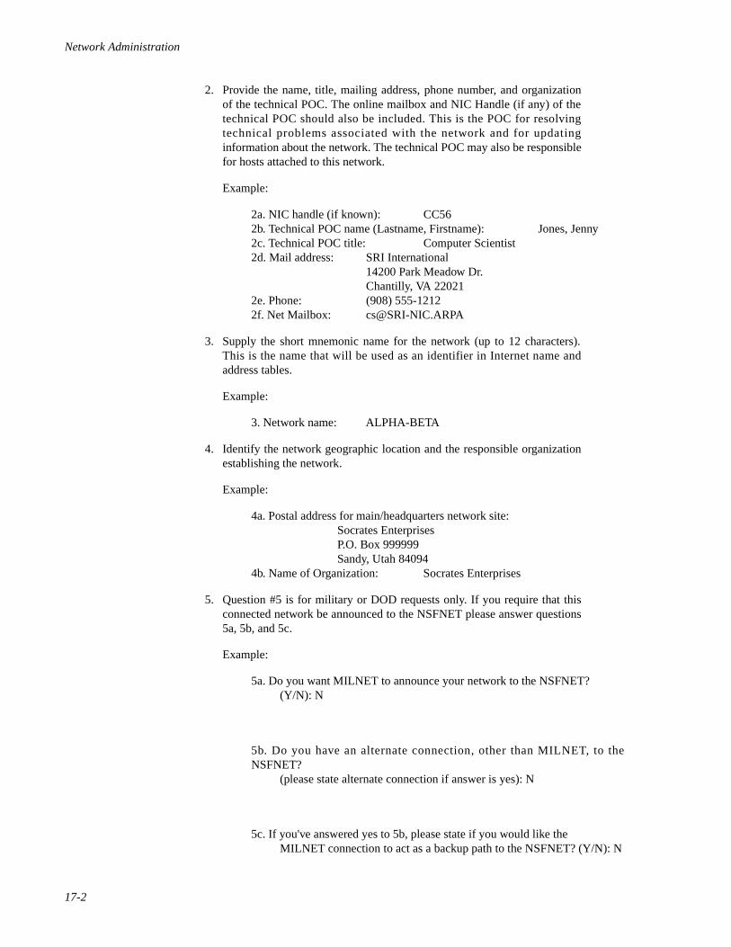
Network Administration
17-2
2. Provide the name, title, mailing address, phone number, and organizationof the technical POC. The online mailbox and NIC Handle (if any) of thetechnical POC should also be included. This is the POC for resolvingtechnical problems associated with the network and for updatinginformation about the network. The technical POC may also be responsiblefor hosts attached to this network.
Example:
2a. NIC handle (if known): CC562b. Technical POC name (Lastname, Firstname): Jones, Jenny2c. Technical POC title: Computer Scientist2d. Mail address: SRI International
14200 Park Meadow Dr.Chantilly, VA 22021
2e. Phone: (908) 555-12122f. Net Mailbox: [email protected]
3. Supply the short mnemonic name for the network (up to 12 characters).This is the name that will be used as an identifier in Internet name andaddress tables.
Example:
3. Network name: ALPHA-BETA
4. Identify the network geographic location and the responsible organizationestablishing the network.
Example:
4a. Postal address for main/headquarters network site:Socrates EnterprisesP.O. Box 999999Sandy, Utah 84094
4b. Name of Organization: Socrates Enterprises
5. Question #5 is for military or DOD requests only. If you require that thisconnected network be announced to the NSFNET please answer questions5a, 5b, and 5c.
Example:
5a. Do you want MILNET to announce your network to the NSFNET?(Y/N): N
5b. Do you have an alternate connection, other than MILNET, to theNSFNET?
(please state alternate connection if answer is yes): N
5c. If you've answered yes to 5b, please state if you would like theMILNET connection to act as a backup path to the NSFNET? (Y/N): N
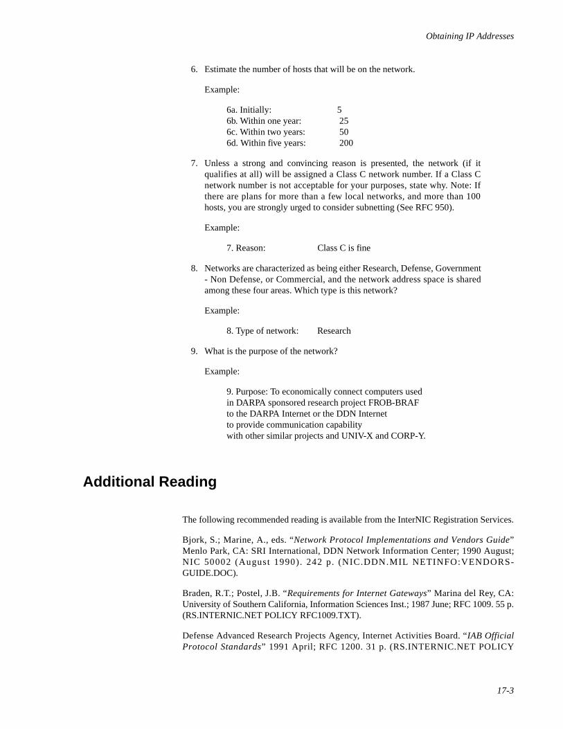
Obtaining IP Addresses
17-3
6. Estimate the number of hosts that will be on the network.
Example:
6a. Initially: 56b. Within one year: 256c. Within two years: 506d. Within five years: 200
7. Unless a strong and convincing reason is presented, the network (if itqualifies at all) will be assigned a Class C network number. If a Class Cnetwork number is not acceptable for your purposes, state why. Note: Ifthere are plans for more than a few local networks, and more than 100hosts, you are strongly urged to consider subnetting (See RFC 950).
Example:
7. Reason: Class C is fine
8. Networks are characterized as being either Research, Defense, Government- Non Defense, or Commercial, and the network address space is sharedamong these four areas. Which type is this network?
Example:
8. Type of network: Research
9. What is the purpose of the network?
Example:
9. Purpose: To economically connect computers usedin DARPA sponsored research project FROB-BRAFto the DARPA Internet or the DDN Internetto provide communication capabilitywith other similar projects and UNIV-X and CORP-Y.
Additional Reading 17
The following recommended reading is available from the InterNIC Registration Services.
Bjork, S.; Marine, A., eds. “Network Protocol Implementations and Vendors Guide”Menlo Park, CA: SRI International, DDN Network Information Center; 1990 August;NIC 50002 (August 1990). 242 p. (NIC.DDN.MIL NETINFO:VENDORS-GUIDE.DOC).
Braden, R.T.; Postel, J.B. “Requirements for Internet Gateways” Marina del Rey, CA:University of Southern California, Information Sciences Inst.; 1987 June; RFC 1009. 55 p.(RS.INTERNIC.NET POLICY RFC1009.TXT).
Defense Advanced Research Projects Agency, Internet Activities Board. “IAB OfficialProtocol Standards” 1991 April; RFC 1200. 31 p. (RS.INTERNIC.NET POLICY

Network Administration
17-4
RFC1200.TXT). Feinler, E.J.; Jacobsen, O.J.; Stahl, M.K.; Ward, C.A., eds. “DDNProtocol Handbook” Menlo Park, CA: SRI International, DDN Network InformationCenter; 1985 December; NIC 50004 and NIC 50005 and NIC 50006. 2749 p.
Garcia-Luna-Aceves, J.J.; Stahl, M.K.; Ward, C.A., eds. “Internet Protocol Handbook”The Domain Name System (DNS) Handbook. Menlo Park, CA: SRI International, Net-work Information Systems Center; 1989 August; NIC 50007. 219 p. AD A214 698.
Kirkpatrick, S.; Stahl, M.K.; Recker, M. “Internet Numbers” Menlo Park, CA: SRIInternational, DDN Network Information Center; 1990 July; RFC 1166. 182 p.(RS.INTERNIC.NET POLICY RFC1166.TXT).
Mogul, J.; Postel, J.B “Internet Standard Subnetting Procedure”. Stanford, CA: StanfordUniversity; 1985 August; RFC 950. 18 p. (RS.INTERNIC.NET POLICY RFC950.TXT).
Postel, J.B. “Internet Control Message Protocol” Marina del Rey, CA: University ofSouthern California, Information Sciences Inst.; 1981 September; RFC 792. 21 p.(RS.INTERNIC.NET POLICY RFC792.TXT).
Postel, J.B. “Transmission Control Protocol” Marina del Rey, CA: University of SouthernCal i fornia, Information Sciences Inst . ; 1981 September ; RFC 793. 85 p.(RS.INTERNIC.NET POLICY RFC793.TXT).
Postel, J.B. “Address Mappings” Marina del Rey, CA: University of Southern California,Information Sciences Inst.; 1981 September; RFC 796. 7 p. (RS.INTERNIC.NETPOLICY RFC796.TXT). Obsoletes: IEN 115 (NACC 0968-79)
Postel, J.B. “User Datagram Protocol” Marina del Rey, CA: University of SouthernCal i fo rn ia , In format ion Sc iences Inst . ; 1980 August 28; RFC 768. 3 p .(RS.INTERNIC.NET POLICY RFC768.TXT).
Postel, J.B. “Internet Protocol” Marina del Rey, CA: University of Southern California,Information Sciences Inst.; 1981 September; RFC 791. 45 p. (NIC.DDN.MILRFC:RFC791.TXT).
Reynolds, J.K.; Postel, J.B. “Assigned Numbers” Marina del Rey, CA: University ofSouthern California, Information Sciences Inst.; 1990 March; RFC 1060. 86 p.(RS.INTERNIC.NET POLICY RFC1060.TXT).
Reynolds, J.K.; Postel, J.B. “Official Internet Protocols” Marina del Rey, CA: Universityof Southern California, Information Sciences Inst.; 1987 May; RFC 1011. 52 p.(RS.INTERNIC.NET POLICY RFC1011.TXT).
18Obtaining Domain Names
Domain Registration Forms. . . . . . . . . . . . . . . . . . . . . . . . . . . . . . . . . . . . . . . . . . . . 18-1Registering Your Domain Name. . . . . . . . . . . . . . . . . . . . . . . . . . . . . . . . . . . . . 18-1Completing the Domain Registration Form . . . . . . . . . . . . . . . . . . . . . . . . . . . . 18-2Registering for Internet Address to Host Mapping . . . . . . . . . . . . . . . . . . . . . . 18-4
Additional Reading . . . . . . . . . . . . . . . . . . . . . . . . . . . . . . . . . . . . . . . . . . . . . . . . . . 18-5

Network Administration
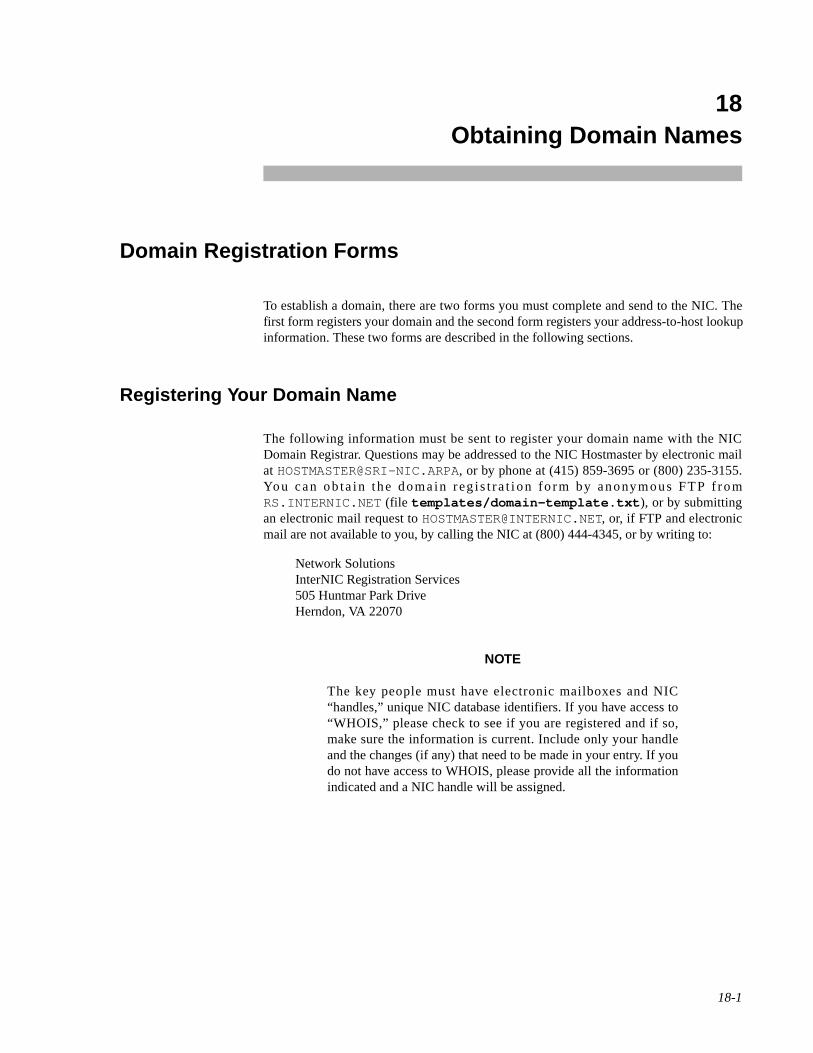
18-1
18Chapter 18Obtaining Domain Names
181818
Domain Registration Forms 18
To establish a domain, there are two forms you must complete and send to the NIC. Thefirst form registers your domain and the second form registers your address-to-host lookupinformation. These two forms are described in the following sections.
Registering Your Domain Name 18
The following information must be sent to register your domain name with the NICDomain Registrar. Questions may be addressed to the NIC Hostmaster by electronic mailat [email protected], or by phone at (415) 859-3695 or (800) 235-3155.You can ob ta in the doma in reg is t ra t i on fo rm by anonymous FTP f romRS.INTERNIC.NET (file templates/domain-template.txt ), or by submittingan electronic mail request to [email protected], or, if FTP and electronicmail are not available to you, by calling the NIC at (800) 444-4345, or by writing to:
Network SolutionsInterNIC Registration Services505 Huntmar Park DriveHerndon, VA 22070
NOTE
The key people must have electronic mailboxes and NIC“handles,” unique NIC database identifiers. If you have access to“WHOIS,” please check to see if you are registered and if so,make sure the information is current. Include only your handleand the changes (if any) that need to be made in your entry. If youdo not have access to WHOIS, please provide all the informationindicated and a NIC handle will be assigned.
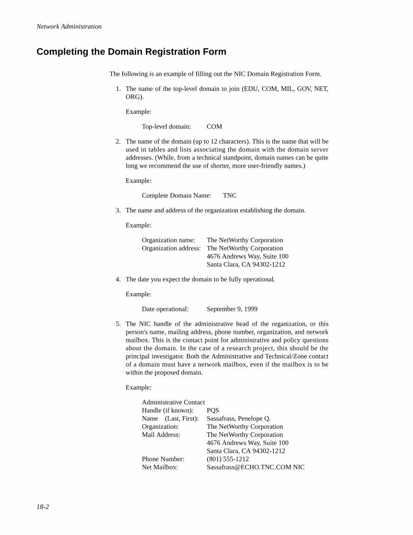
Network Administration
18-2
Completing the Domain Registration Form 18
The following is an example of filling out the NIC Domain Registration Form.
1. The name of the top-level domain to join (EDU, COM, MIL, GOV, NET,ORG).
Example:
Top-level domain: COM
2. The name of the domain (up to 12 characters). This is the name that will beused in tables and lists associating the domain with the domain serveraddresses. (While, from a technical standpoint, domain names can be quitelong we recommend the use of shorter, more user-friendly names.)
Example:
Complete Domain Name: TNC
3. The name and address of the organization establishing the domain.
Example:
Organization name: The NetWorthy CorporationOrganization address: The NetWorthy Corporation
4676 Andrews Way, Suite 100Santa Clara, CA 94302-1212
4. The date you expect the domain to be fully operational.
Example:
Date operational: September 9, 1999
5. The NIC handle of the administrative head of the organization, or thisperson's name, mailing address, phone number, organization, and networkmailbox. This is the contact point for administrative and policy questionsabout the domain. In the case of a research project, this should be theprincipal investigator. Both the Administrative and Technical/Zone contactof a domain must have a network mailbox, even if the mailbox is to bewithin the proposed domain.
Example:
Administrative ContactHandle (if known): PQS Name (Last, First): Sassafrass, Penelope Q.Organization: The NetWorthy CorporationMail Address: The NetWorthy Corporation
4676 Andrews Way, Suite 100Santa Clara, CA 94302-1212
Phone Number: (801) 555-1212Net Mailbox: [email protected] NIC
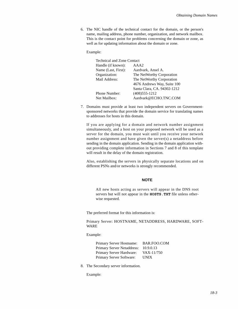
Obtaining Domain Names
18-3
6. The NIC handle of the technical contact for the domain, or the person'sname, mailing address, phone number, organization, and network mailbox.This is the contact point for problems concerning the domain or zone, aswell as for updating information about the domain or zone.
Example:
Technical and Zone ContactHandle (if known): AAA2Name (Last, First): Aardvark, Ansel A.Organization: The NetWorthy CorporationMail Address: The NetWorthy Corporation
4676 Andrews Way, Suite 100 Santa Clara, CA. 94302-1212Phone Number: (408)555-1212Net Mailbox: [email protected]
7. Domains must provide at least two independent servers on Government-sponsored networks that provide the domain service for translating namesto addresses for hosts in this domain.
If you are applying for a domain and network number assignmentsimultaneously, and a host on your proposed network will be used as aserver for the domain, you must wait until you receive your networknumber assignment and have given the server(s) a netaddress beforesending in the domain application. Sending in the domain application with-out providing complete information in Sections 7 and 8 of this templatewill result in the delay of the domain registration.
Also, establishing the servers in physically separate locations and ondifferent PSNs and/or networks is strongly recommended.
NOTE
All new hosts acting as servers will appear in the DNS rootservers but will not appear in the HOSTS.TXT file unless other-wise requested.
The preferred format for this information is:
Primary Server: HOSTNAME, NETADDRESS, HARDWARE, SOFT-WARE
Example:
Primary Server Hostname: BAR.FOO.COM Primary Server Netaddress: 10.9.0.13 Primary Server Hardware: VAX-11/750Primary Server Software: UNIX
8. The Secondary server information.
Example:
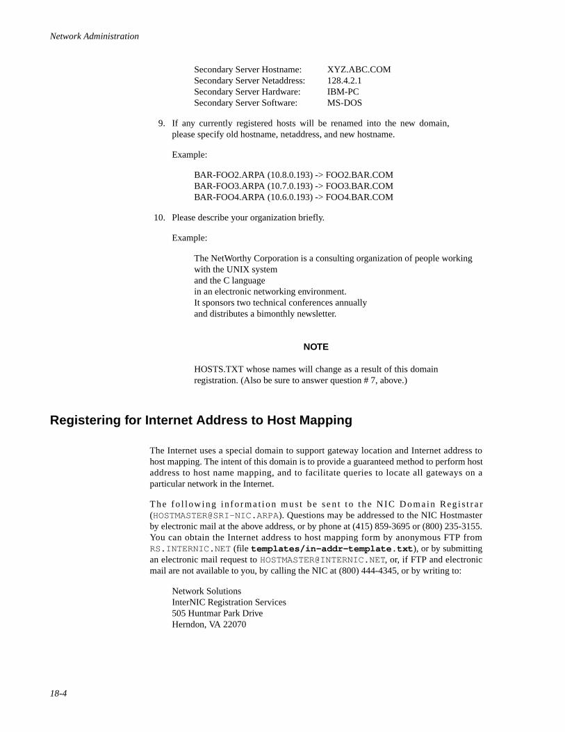
Network Administration
18-4
Secondary Server Hostname: XYZ.ABC.COM Secondary Server Netaddress: 128.4.2.1 Secondary Server Hardware: IBM-PCSecondary Server Software: MS-DOS
9. If any currently registered hosts will be renamed into the new domain,please specify old hostname, netaddress, and new hostname.
Example:
BAR-FOO2.ARPA (10.8.0.193) -> FOO2.BAR.COM BAR-FOO3.ARPA (10.7.0.193) -> FOO3.BAR.COM BAR-FOO4.ARPA (10.6.0.193) -> FOO4.BAR.COM
10. Please describe your organization briefly.
Example:
The NetWorthy Corporation is a consulting organization of people workingwith the UNIX systemand the C languagein an electronic networking environment.It sponsors two technical conferences annuallyand distributes a bimonthly newsletter.
NOTE
HOSTS.TXT whose names will change as a result of this domainregistration. (Also be sure to answer question # 7, above.)
Registering for Internet Address to Host Mapping 18
The Internet uses a special domain to support gateway location and Internet address tohost mapping. The intent of this domain is to provide a guaranteed method to perform hostaddress to host name mapping, and to facilitate queries to locate all gateways on aparticular network in the Internet.
The fo l low ing in fo rma t ion must be sen t to the NIC Domain Reg is t ra r([email protected]). Questions may be addressed to the NIC Hostmasterby electronic mail at the above address, or by phone at (415) 859-3695 or (800) 235-3155.You can obtain the Internet address to host mapping form by anonymous FTP fromRS.INTERNIC.NET (file templates/in-addr-template.txt ), or by submittingan electronic mail request to [email protected], or, if FTP and electronicmail are not available to you, by calling the NIC at (800) 444-4345, or by writing to:
Network SolutionsInterNIC Registration Services505 Huntmar Park DriveHerndon, VA 22070
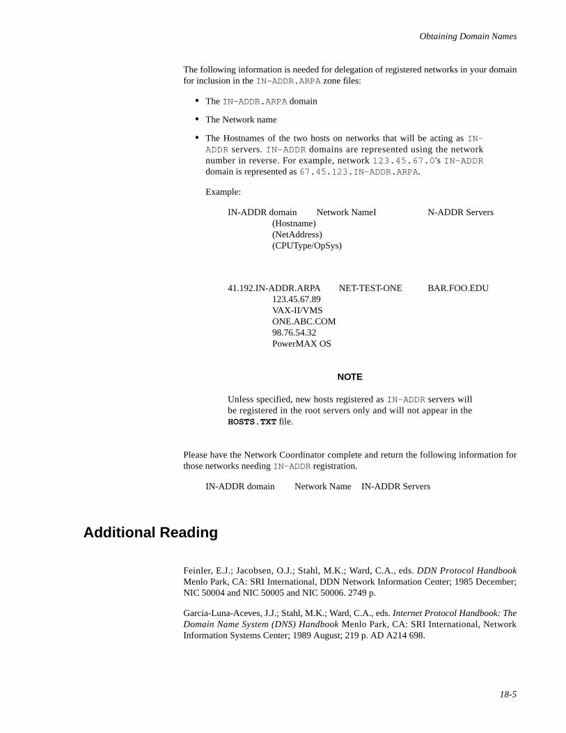
Obtaining Domain Names
18-5
The following information is needed for delegation of registered networks in your domainfor inclusion in the IN-ADDR.ARPA zone files:
• The IN-ADDR.ARPA domain
• The Network name
• The Hostnames of the two hosts on networks that will be acting as IN-ADDR servers. IN-ADDR domains are represented using the networknumber in reverse. For example, network 123.45.67.0 's IN-ADDRdomain is represented as 67.45.123.IN-ADDR.ARPA .
Example:
IN-ADDR domain Network NameI N-ADDR Servers(Hostname)(NetAddress)(CPUType/OpSys)
41.192.IN-ADDR.ARPA NET-TEST-ONE BAR.FOO.EDU123.45.67.89VAX-II/VMSONE.ABC.COM98.76.54.32PowerMAX OS
NOTE
Unless specified, new hosts registered as IN-ADDR servers willbe registered in the root servers only and will not appear in theHOSTS.TXT file.
Please have the Network Coordinator complete and return the following information forthose networks needing IN-ADDR registration.
IN-ADDR domain Network Name IN-ADDR Servers
Additional Reading 18
Feinler, E.J.; Jacobsen, O.J.; Stahl, M.K.; Ward, C.A., eds. DDN Protocol HandbookMenlo Park, CA: SRI International, DDN Network Information Center; 1985 December;NIC 50004 and NIC 50005 and NIC 50006. 2749 p.
Garcia-Luna-Aceves, J.J.; Stahl, M.K.; Ward, C.A., eds. Internet Protocol Handbook: TheDomain Name System (DNS) Handbook Menlo Park, CA: SRI International, NetworkInformation Systems Center; 1989 August; 219 p. AD A214 698.
Network Administration
18-6
Postel, J.B.; Reynolds, J.K. Domain Requirements Marina del Rey, CA: University ofSouthern California, Information Sciences Inst.; 1984 October; RFC 920. 14 p.(RS.INTERNIC.NET POLICY RFC920.TXT).
Harrenstien, K.; Stahl, M.K.; Feinler, E.J. DoD Internet Host Table Specification MenloPark, CA: SRI International, DDN Network Information Center; 1985 October; RFC 952.6 p. (RS.INTERNIC.NET POLICY RFC952.TXT). Obsoletes: RFC 810
Harrenstien, K.; Stahl, M.K.; Feinler, E.J. Hostname Server Menlo Park, CA: SRIInternational, DDN Network Information Center; 1985 October; RFC 953. 5 p.(NIC.DDN.MIL RFC:RFC953.TXT). Obsoletes: RFC 811
Partridge, C. Mail Routing and the Domain System Cambridge, MA: BBN Labs., Inc.;1986 January; RFC 974. 7 p. (RS.INTERNIC.NET POLICY RFC974.TXT).
Lazear, W.D. MILNET Name Domain Transition McLean, VA: MITRE Corp.; 1987November; RFC 1031. 10 p. (RS.INTERNIC.NET POLICY RFC1031.TXT).
Stahl, M.K. Domain Administrators Guide Menlo Park, CA: SRI International, DDN Net-work Information Center; 1987 November; RFC 1032. 14 p. (RS.INTERNIC.NETPOLICY RFC1032.TXT).
Lottor, M. Domain Administrators Operations Guide Menlo Park, CA: SRI International,DDN Network In fo rmat ion Cen te r ; 1987 November ; RFC 103 3 . 22 p .(RS.INTERNIC.NET POLICY RFC1033.TXT).
Mockapetris, P. Domain Names - Concepts and Facilities Marina del Rey, CA: Universityof Southern California, Information Sciences Inst.; 1987 November; RFC 1034. 55 p.(RS.INTERNIC.NET POLICY RFC1034.TXT). Updated-by: RFC 1101 Obsoletes: RFC973; RFC 882; RFC 883
Mockapetris, P. Domain names - Implementation and Specification Marina del Rey, CA:University of Southern California, Information Sciences Inst.; 1987 November; RFC1035. 55 p. (RS.INTERNIC.NET POLICY RFC1035.TXT). Updated-by: RFC 1101Obsoletes: RFC 973; RFC 882; RFC 883
Mockapetris, P. DNS Encoding of Network Names and Other Types Marina del Rey, CA:University of Southern California, Information Sciences Inst.; 1989 April; RFC 1101. 14p. (RS.INTERNIC.NET POLICY RFC1101.TXT). Updates: RFC 1034; RFC 1035
19Network Time Synchronization
Introduction to Network Time Synchronization Administration. . . . . . . . . . . . . . . . 19-1Administering the xntpd Network Time Protocol Daemon. . . . . . . . . . . . . . . . . . . . 19-1Configuring Clock Synchronization . . . . . . . . . . . . . . . . . . . . . . . . . . . . . . . . . . . . . 19-2
Time Synchronization Example . . . . . . . . . . . . . . . . . . . . . . . . . . . . . . . . . . . . . 19-3Configuring NTP With ntp.conf . . . . . . . . . . . . . . . . . . . . . . . . . . . . . . . . . . . . . . . . 19-4
Configuration Statements . . . . . . . . . . . . . . . . . . . . . . . . . . . . . . . . . . . . . . . . . . 19-5Example ntp.conf File . . . . . . . . . . . . . . . . . . . . . . . . . . . . . . . . . . . . . . . . . . . . 19-6
Advanced NTP Topics . . . . . . . . . . . . . . . . . . . . . . . . . . . . . . . . . . . . . . . . . . . . . . . . 19-7How the NTP Daemon Operates . . . . . . . . . . . . . . . . . . . . . . . . . . . . . . . . . . . . 19-7The clock.txt File . . . . . . . . . . . . . . . . . . . . . . . . . . . . . . . . . . . . . . . . . . . . . . . . 19-7The driftfile. . . . . . . . . . . . . . . . . . . . . . . . . . . . . . . . . . . . . . . . . . . . . . . . . . . . . 19-8Association Modes . . . . . . . . . . . . . . . . . . . . . . . . . . . . . . . . . . . . . . . . . . . . . . . 19-9Address-and-mask Configuration Facility . . . . . . . . . . . . . . . . . . . . . . . . . . . . . 19-9Authentication . . . . . . . . . . . . . . . . . . . . . . . . . . . . . . . . . . . . . . . . . . . . . . . . . . 19-10The keys Statement. . . . . . . . . . . . . . . . . . . . . . . . . . . . . . . . . . . . . . . . . . . . . . . 19-11Key File . . . . . . . . . . . . . . . . . . . . . . . . . . . . . . . . . . . . . . . . . . . . . . . . . . . . . . . 19-11The authdelay Statement . . . . . . . . . . . . . . . . . . . . . . . . . . . . . . . . . . . . . . . . . . 19-12Name Resolution . . . . . . . . . . . . . . . . . . . . . . . . . . . . . . . . . . . . . . . . . . . . . . . . 19-12Clock Support Overview . . . . . . . . . . . . . . . . . . . . . . . . . . . . . . . . . . . . . . . . . . 19-13Converting ntpd Configuration Files to xntpd . . . . . . . . . . . . . . . . . . . . . . . . . . 19-14Dealing With a Mixture of xntpd and ntpd Servers . . . . . . . . . . . . . . . . . . . . . . 19-14
NTP Examples. . . . . . . . . . . . . . . . . . . . . . . . . . . . . . . . . . . . . . . . . . . . . . . . . . . . . . 19-15Testing and Tuning Your NTP Subnet . . . . . . . . . . . . . . . . . . . . . . . . . . . . . . . . . . . . 19-18Related xntp Commands . . . . . . . . . . . . . . . . . . . . . . . . . . . . . . . . . . . . . . . . . . . . . . 19-19
Examples . . . . . . . . . . . . . . . . . . . . . . . . . . . . . . . . . . . . . . . . . . . . . . . . . . . . . . 19-20Troubleshooting xntpd. . . . . . . . . . . . . . . . . . . . . . . . . . . . . . . . . . . . . . . . . . . . . . . . 19-22Administering the timed Time Synchronization Daemon . . . . . . . . . . . . . . . . . . . . . 19-23Guidelines . . . . . . . . . . . . . . . . . . . . . . . . . . . . . . . . . . . . . . . . . . . . . . . . . . . . . . . . . 19-24
Options . . . . . . . . . . . . . . . . . . . . . . . . . . . . . . . . . . . . . . . . . . . . . . . . . . . . . . . . 19-25Daily Operation . . . . . . . . . . . . . . . . . . . . . . . . . . . . . . . . . . . . . . . . . . . . . . . . . . . . . 19-25

Network Administration
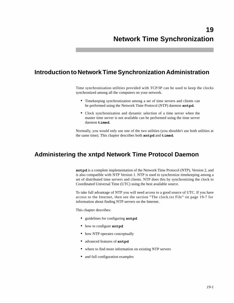
19-1
19Chapter 19Network Time Synchronization
191919
Introduction to Network Time Synchronization Administration 19
Time synchronization utilities provided with TCP/IP can be used to keep the clockssynchronized among all the computers on your network.
• Timekeeping synchronization among a set of time servers and clients canbe performed using the Network Time Protocol (NTP) daemon xntpd .
• Clock synchronization and dynamic selection of a time server when themaster time server is not available can be performed using the time serverdaemon timed .
Normally, you would only use one of the two utilities (you shouldn't use both utilities atthe same time). This chapter describes both xntpd and timed .
Administering the xntpd Network Time Protocol Daemon 19
xntpd is a complete implementation of the Network Time Protocol (NTP), Version 2, andis also compatible with NTP Version 1. NTP is used to synchronize timekeeping among aset of distributed time servers and clients. NTP does this by synchronizing the clock toCoordinated Universal Time (UTC) using the best available source.
To take full advantage of NTP you will need access to a good source of UTC. If you haveaccess to the Internet, then see the section “The clock.txt File” on page 19-7 forinformation about finding NTP servers on the Internet.
This chapter describes:
• guidelines for configuring xntpd
• how to configure xntpd
• how NTP operates conceptually
• advanced features of xntpd
• where to find more information on existing NTP servers
• and full configuration examples
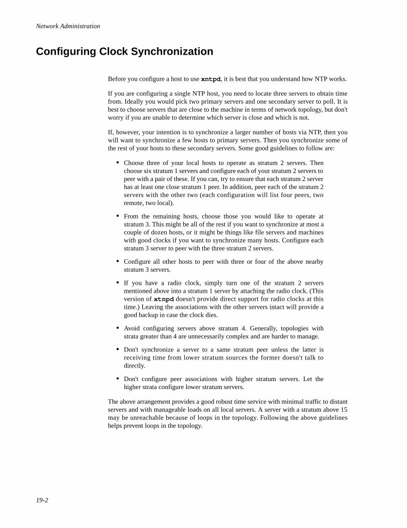
Network Administration
19-2
Configuring Clock Synchronization 19
Before you configure a host to use xntpd , it is best that you understand how NTP works.
If you are configuring a single NTP host, you need to locate three servers to obtain timefrom. Ideally you would pick two primary servers and one secondary server to poll. It isbest to choose servers that are close to the machine in terms of network topology, but don'tworry if you are unable to determine which server is close and which is not.
If, however, your intention is to synchronize a larger number of hosts via NTP, then youwill want to synchronize a few hosts to primary servers. Then you synchronize some ofthe rest of your hosts to these secondary servers. Some good guidelines to follow are:
• Choose three of your local hosts to operate as stratum 2 servers. Thenchoose six stratum 1 servers and configure each of your stratum 2 servers topeer with a pair of these. If you can, try to ensure that each stratum 2 serverhas at least one close stratum 1 peer. In addition, peer each of the stratum 2servers with the other two (each configuration will list four peers, tworemote, two local).
• From the remaining hosts, choose those you would like to operate atstratum 3. This might be all of the rest if you want to synchronize at most acouple of dozen hosts, or it might be things like file servers and machineswith good clocks if you want to synchronize many hosts. Configure eachstratum 3 server to peer with the three stratum 2 servers.
• Configure all other hosts to peer with three or four of the above nearbystratum 3 servers.
• If you have a radio clock, simply turn one of the stratum 2 serversmentioned above into a stratum 1 server by attaching the radio clock. (Thisversion of xtnpd doesn't provide direct support for radio clocks at thistime.) Leaving the associations with the other servers intact will provide agood backup in case the clock dies.
• Avoid configuring servers above stratum 4. Generally, topologies withstrata greater than 4 are unnecessarily complex and are harder to manage.
• Don't synchronize a server to a same stratum peer unless the latter isreceiving time from lower stratum sources the former doesn't talk todirectly.
• Don't configure peer associations with higher stratum servers. Let thehigher strata configure lower stratum servers.
The above arrangement provides a good robust time service with minimal traffic to distantservers and with manageable loads on all local servers. A server with a stratum above 15may be unreachable because of loops in the topology. Following the above guidelineshelps prevent loops in the topology.
Network Time Synchronization
19-3
Time Synchronization Example 19
In the following example:
• Zite , HGWells , and DrWho are stratum 2 servers for Sci.com .
• Zite peers with two stratum 1 servers: percival.cs.purdue.eduand deidinator.psyc.chi.il.us .
• HGWells peers with two stratum 1 servers:asmus1.genetics.uga.edu and bedivere.cs.purdue.edu.
• DrWho peers with two stratum 1 servers: nehd.gov andberdie.athens.ga.us .
• Zite peers with HGWells and DrWho.
• HGWells peers with Zite and DrWho.
• DrWho peers with Zite and HGWells .
• moondoggie and the rest of the machines at sci.com are at stratum 3and peer with the three stratum 2 machines.
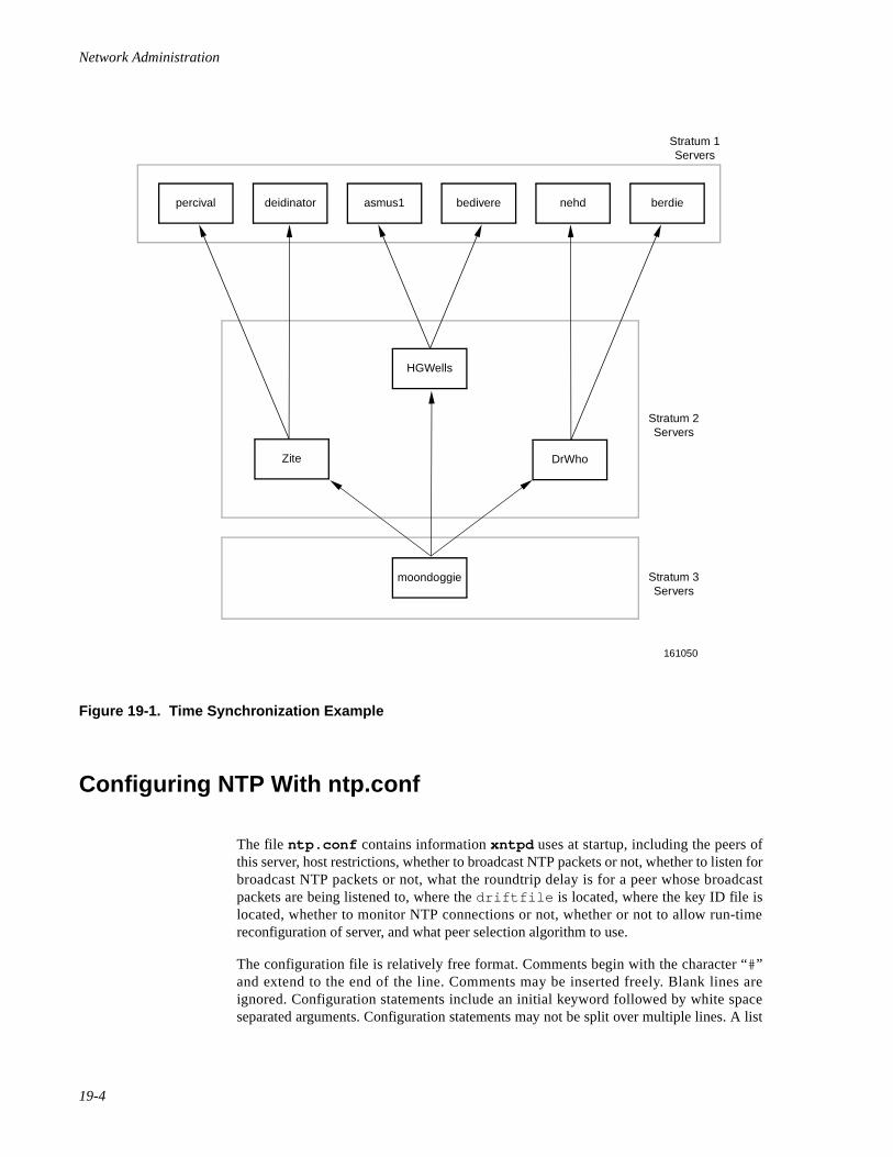
Network Administration
19-4
Figure 19-1. Time Synchronization Example
Configuring NTP With ntp.conf 19
The file ntp.conf contains information xntpd uses at startup, including the peers ofthis server, host restrictions, whether to broadcast NTP packets or not, whether to listen forbroadcast NTP packets or not, what the roundtrip delay is for a peer whose broadcastpackets are being listened to, where the driftfile is located, where the key ID file islocated, whether to monitor NTP connections or not, whether or not to allow run-timereconfiguration of server, and what peer selection algorithm to use.
The configuration file is relatively free format. Comments begin with the character “#”and extend to the end of the line. Comments may be inserted freely. Blank lines areignored. Configuration statements include an initial keyword followed by white spaceseparated arguments. Configuration statements may not be split over multiple lines. A list
percival deidinator asmus1
HGWells
Stratum 3Servers
Stratum 2Servers
Stratum 1Servers
moondoggie
Zite DrWho
bedivere nehd berdie
161050
Network Time Synchronization
19-5
of the configuration statements with their arguments are listed below. Optional argumentsare delimited by square brackets ([]), while alternatives are separated by pipe signs (|).
Configuration Statements 19
peer host_address [ key keyid ] [ minpoll ]Specifies that the named host is to be polled in symmetric activemode. host_address is the IP address of the host to poll. Theargument key indicates that all packets sent to the address are toinclude authentication fields encrypted using the key numberkeyid. The default is to not include authentication fields. Theargument minpoll indicates that the polling interval should bekept at the minimum. This argument should only be used fordebugging purposes.
server host_address [ key keyid ] [ minpoll ]Specifies that the host at the given host_address is to be polled inclient mode. The arguments are the same as described for thepeer statement above.
broadcast host_address [ key keyid ] [ minpoll ]Specifies that xntpd is to broadcast NTP to the specifiedhost_address. host_address should be the broadcast address on(one of) your local network(s). The arguments are the same asdescribed for the peer statement above.
precision precision_valueIndicates the precision of the local timekeeping. See the section“Testing and Tuning Your NTP Subnet” on page 19-18 for furtherinformation on setting the precision.
driftfile filename Specifies that the file filename is to be used to record the drift(frequency error) computed by xntpd .
monitor yes | no Indicates whether or not xntpd monitoring function should beenabled. The default is no.
broadcastclient yes | noIndicates whether or not the local server should listen for, andattempt to synchronize to, broadcast NTP. The default is no.
broadcastdelay secondsSpecifies the round trip delay to the host whose broadcasts arebeing synchronized to, where seconds is the number of seconds todelay. The default is 0.008 seconds.
authenticate yes | noIndicates whether or not the local server operates in authenticatemode. The default is no.
authdelay seconds Indicates the amount of time it takes to encrypt an NTPauthentication field on the local computer, where seconds is thenumber of seconds to delay.
Network Administration
19-6
keys filename Specifies the name of the file that contains the encryption keys tobe used by xntpd .
trustedkey keyid [ ... ]Specifies which encryption key IDs are the trusted ones for thepurpose of determining peers suitable for time synchronization,when authentication is enabled.
requestkey keyid Specifies which key ID is to be used to authenticate run timereconfiguration requests made by xntpdc (mode 7 controlmessages). If no requestkey statement is included, the run-time reconfiguration facility is disabled.
controlkey keyid Specifies which key ID is to be used to authenticate run timereconfiguration requests made by ntpq (mode 6 controlmessages). If no controlkey statement is included, then mode6 control messages are ignored.
restrict address [ mask ] [ flag ] [ ... ]Specifies which hosts and networks are allowed to interoperatewith the daemon.
trap host_address [ port port_number ] [ interface interface_address ]Configures a trap receiver at the given host address and portnumber.
maxskew seconds Sets the system maximum skew parameter to seconds.
select algorithm_numberSelects one of five selection algorithms. The default is 1.
resolver path/xntpresIndicates the full path to the xntpres program. (This should beset to /usr/sbin/xntpres .)
Example ntp.conf File 19
Here is an example of a minimal ntp.conf file for the host zite.sci.com . The fourpeer declarations tell xntpd the servers it needs to poll. The last declaration tells xntpdthe name of the file in which to store the frequency error of the system clock. For now,suffice it to say that every ntp.conf file should contain this declaration. And lastly, thisserver is expected to operate as a stratum 2 server, since two of the four servers (the firsttwo) declared have hardware clocks and typically run at stratum 1.
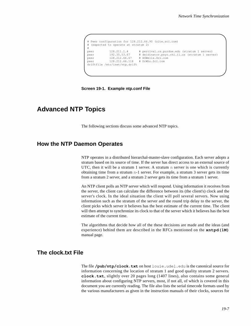
Network Time Synchronization
19-7
Screen 19-1. Example ntp.conf File
Advanced NTP Topics 19
The following sections discuss some advanced NTP topics.
How the NTP Daemon Operates 19
NTP operates in a distributed hierarchal-master-slave configuration. Each server adopts astratum based on its source of time. If the server has direct access to an external source ofUTC, then it will be a stratum 1 server. A stratum n server is one which is currentlyobtaining time from a stratum n-1 server. For example, a stratum 3 server gets its timefrom a stratum 2 server, and a stratum 2 server gets its time from a stratum 1 server.
An NTP client polls an NTP server which will respond. Using information it receives fromthe server, the client can calculate the difference between its (the client's) clock and theserver's clock. In the ideal situation the client will poll several servers. Now usinginformation such as the stratum of the server and the round trip delay to the server, theclient picks which server it believes has the best estimate of the current time. The clientwill then attempt to synchronize its clock to that of the server which it believes has the bestestimate of the current time.
The algorithms that decide how all of the these decisions are made and the ideas (andexperience) behind them are described in the RFCs mentioned on the xntpd(1M)manual page.
The clock.txt File 19
The file /pub/ntp/clock.txt on host louie.udel.edu is the canonical source forinformation concerning the location of stratum 1 and good quality stratum 2 servers.clock.txt , slightly over 20 pages long (1407 lines), also contains some generalinformation about configuring NTP servers, most, if not all, of which is covered in thisdocument you are currently reading. The file also lists the serial timecode formats used bythe various manufacturers as given in the instruction manuals of their clocks, sources for
# Peer configuration for 128.212.66.90 (zite.sci.com)# (expected to operate at stratum 2)#peer 128.211.1.4 # percival.cs.purdue.edu (stratum 1 server)peer 192.35.53.67 # deidinator.psyc.chi.il.us (stratum 1 server)peer 128.212.66.67 # HGWells.Sci.compeer 128.212.66.118 # DrWho.Sci.comdriftfile /etc/inet/ntp.drift
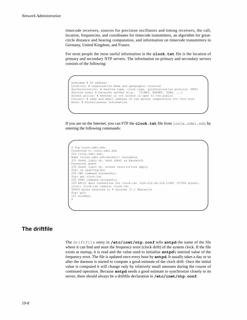
Network Administration
19-8
timecode receivers, sources for precision oscillators and timing receivers, the call,location, frequencies, and coordinates for timecode transmitters, an algorithm for great-circle distance and bearing computation, and information on timecode transmitters inGermany, United Kingdom, and France.
For most people the most useful information in the clock.txt file is the location ofprimary and secondary NTP servers. The information on primary and secondary serversconsists of the following:
If you are on the Internet, you can FTP the clock.txt file from louie.udel.edu byentering the following commands:
The driftfile 19
The driftfile entry in /etc/inet/ntp.conf tells xntpd the name of the filewhere it can find and store the frequency error (clock drift) of the system clock. If the fileexists at startup, it is read and the value used to initialize xntpd 's internal value of thefrequency error. The file is updated once every hour by xntpd . It usually takes a day or soafter the daemon is started to compute a good estimate of the clock drift. Once the initialvalue is computed it will change only by relatively small amounts during the course ofcontinued operation. Because xntpd needs a good estimate to synchronize closely to itsserver, there should always be a driftfile declaration in /etc/inet/ntp.conf .
hostname # IP addressLocation: # organization Name and geographic locationSynchronization: # machine type, clock type, synchronization protocol (NTP)Service area: # networks served (e.g., CICNET, NSFNET, SURA, ...)Access policy: # whether or not access is open to the publicContact: # name and email address of the person responsible for this hostNote: # miscellaneous information
$ ftp louie.udel.eduConnected to louie.udel.edu220 louie.udel.edu.Name (louie.udel.edu:muckel): anonymous331 Guest login ok, send ident as password.Password: guest230 Guest login ok, access restrictions apply.ftp> cd /pub/ntp/doc250 CWD command successful.ftp> get clock.txt200 PORT command successful.150 ASCII data connection for clock.txt (128.212.66.118,1198) (57002 bytes).local: clock.txt remote: clock.txt58409 bytes received in 8 seconds (7.1 Kbytes/s)ftp> quit221 Goodbye.$
Network Time Synchronization
19-9
Association Modes 19
There are a number of modes in which NTP servers can associate with each other, with themode of each server in the pair indicating the behavior the other server can expect from it.In particular, when configuring a server to obtain time from other servers, there is a choiceof two modes which may be alternatively used. Configuring an association in symmetricactive mode (usually indicated by a peer declaration in configuration files) indicates tothe remote server that your system wants to obtain time from the remote server and thatyour system also is willing to supply time to the remote server if need be. Configuring anassociation in client mode (usually indicated by a server declaration in configuration files)indicates that the system wants to obtain time from the remote server, but that the systemis not willing to provide time to the remote. It is recommended that symmetric activemode should be used for configuring all peer associations between NTP daemons (orstateful NTP entities). Client mode is for use by boot time date-setting programs and thelike, which really have no time to provide and which don't retain state about associationsover the longer term.
Address-and-mask Configuration Facility 19
The address-and-mask configuration facility supported by xntpd is quite flexible andgeneral. However the user interface is not so nice. For this reason it is probably worthdoing an example here.
Briefly, the facility works as follows. There is an internal list, each entry of which holds anaddress, a mask, and a set of flags. On receipt of a packet, the source address of the packetis compared to each entry in the list, with a match being posted when the followingcondition is true:
( source_addr & mask) == ( address & mask)
A particular source address may match several list entries. In this case, the entry with themost one bits in the mask is chosen. The flags associated with this entry are returned.
In the current implementation the flags always add restrictions. In effect, an entry with noflags set leaves matching hosts unrestricted. An entry can be added to the internal listusing a restrict statement. The flags associated with the entry are specified textually.The ignore flag indicates that all packets from hosts matching this entry will be ignored.The noquery flag indicates that hosts matching this entry should not be allowed to sendmode 6 and mode 7 packets. The nomodify flag indicates that hosts matching this entryshould not be allowed to do run-time configuration. The notrap flag indicates that hostsmatching this entry will not be allowed to register as trap receiver. The lowpriotrapflag indicates that hosts matching this entry will be given a low priority for the use oftraps. The noserve flag indicates that hosts matching this entry will not be allowed tosend packets other than mode 6 or mode 7 (they are denied time service). The nopeerflag indicates that hosts matching this entry will not be considered as a peer. Thenotrust flag indicates that hosts matching this entry, while treated normally in otherrespects, shouldn't be trusted for synchronization.
Now the example. Suppose you are running the server on a host whose address is128.212.66.67 . You would like to ensure that run-time reconfiguration requests canonly be made from the local host, and that the server only ever synchronizes to one of a
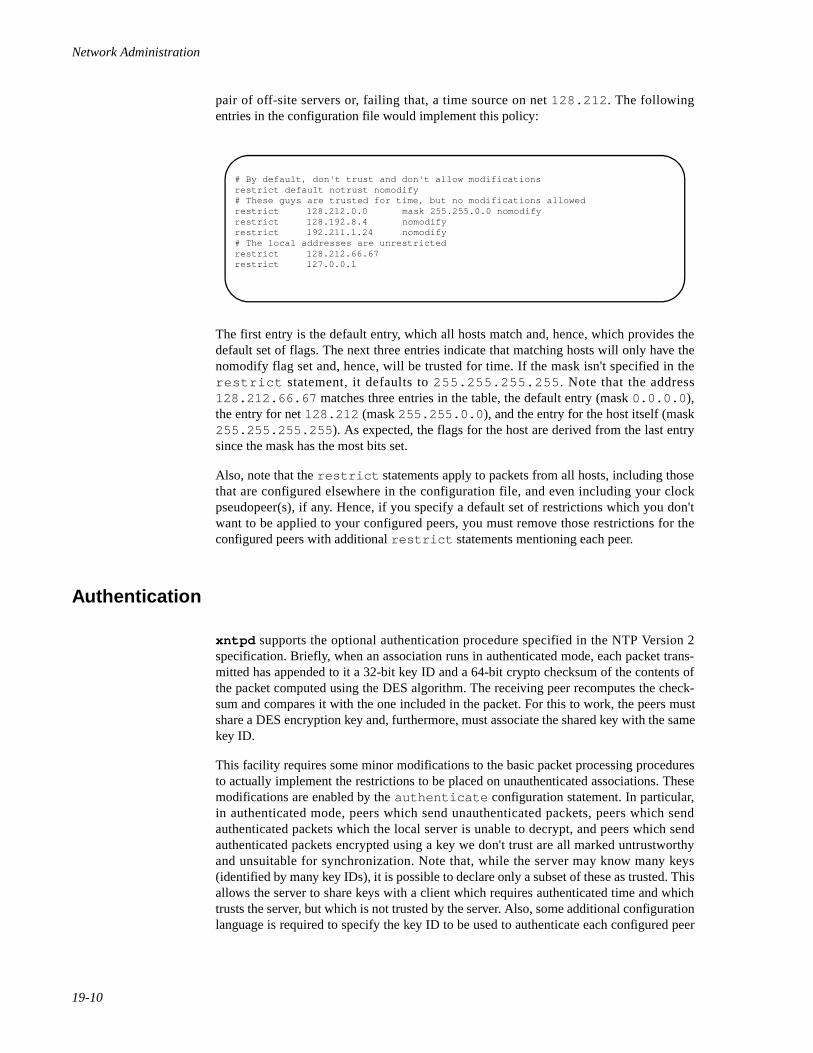
Network Administration
19-10
pair of off-site servers or, failing that, a time source on net 128.212 . The followingentries in the configuration file would implement this policy:
The first entry is the default entry, which all hosts match and, hence, which provides thedefault set of flags. The next three entries indicate that matching hosts will only have thenomodify flag set and, hence, will be trusted for time. If the mask isn't specified in therestrict statement, it defaults to 255.255.255.255 . Note that the address128.212.66.67 matches three entries in the table, the default entry (mask 0.0.0.0 ),the entry for net 128.212 (mask 255.255.0.0 ), and the entry for the host itself (mask255.255.255.255 ). As expected, the flags for the host are derived from the last entrysince the mask has the most bits set.
Also, note that the restrict statements apply to packets from all hosts, including thosethat are configured elsewhere in the configuration file, and even including your clockpseudopeer(s), if any. Hence, if you specify a default set of restrictions which you don'twant to be applied to your configured peers, you must remove those restrictions for theconfigured peers with additional restrict statements mentioning each peer.
Authentication 19
xntpd supports the optional authentication procedure specified in the NTP Version 2specification. Briefly, when an association runs in authenticated mode, each packet trans-mitted has appended to it a 32-bit key ID and a 64-bit crypto checksum of the contents ofthe packet computed using the DES algorithm. The receiving peer recomputes the check-sum and compares it with the one included in the packet. For this to work, the peers mustshare a DES encryption key and, furthermore, must associate the shared key with the samekey ID.
This facility requires some minor modifications to the basic packet processing proceduresto actually implement the restrictions to be placed on unauthenticated associations. Thesemodifications are enabled by the authenticate configuration statement. In particular,in authenticated mode, peers which send unauthenticated packets, peers which sendauthenticated packets which the local server is unable to decrypt, and peers which sendauthenticated packets encrypted using a key we don't trust are all marked untrustworthyand unsuitable for synchronization. Note that, while the server may know many keys(identified by many key IDs), it is possible to declare only a subset of these as trusted. Thisallows the server to share keys with a client which requires authenticated time and whichtrusts the server, but which is not trusted by the server. Also, some additional configurationlanguage is required to specify the key ID to be used to authenticate each configured peer
# By default, don't trust and don't allow modificationsrestrict default notrust nomodify# These guys are trusted for time, but no modifications allowedrestrict 128.212.0.0 mask 255.255.0.0 nomodifyrestrict 128.192.8.4 nomodifyrestrict 192.211.1.24 nomodify# The local addresses are unrestrictedrestrict 128.212.66.67restrict 127.0.0.1
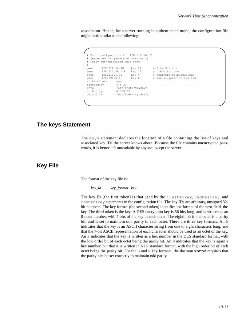
Network Time Synchronization
19-11
association. Hence, for a server running in authenticated mode, the configuration filemight look similar to the following:
The keys Statement 19
The keys statement declares the location of a file containing the list of keys andassociated key IDs the server knows about. Because the file contains unencrypted pass-words, it is better left unreadable by anyone except the server.
Key File 19
The format of the key file is:
key_id key_format key
The key ID (the first token) is that used by the trustedkey , requestkey , andcontrolkey statements in the configuration file. The key IDs are arbitrary, unsigned 32-bit numbers. The key format (the second token) identifies the format of the next field, thekey. The third token is the key. A DES encryption key is 56 bits long, and is written as an8-octet number, with 7 bits of the key in each octet. The eighth bit in the octet is a paritybit, and is set to maintain odd parity in each octet. There are three key formats. An Aindicates that the key is an ASCII character string from one to eight characters long, andthat the 7-bit ASCII representation of each character should be used as an octet of the key.An S indicates that the key is written as a hex number in the DES standard format, withthe low order bit of each octet being the parity bit. An N indicates that the key is again ahex number, but that it is written in NTP standard format, with the high order bit of eachoctet being the parity bit. For the S and N key formats, the daemon xntpd requires thatthe parity bits be set correctly to maintain odd parity.
# Peer configuration for 128.212.66.67# (expected to operate at stratum 2)# Fully authenticated this time#peer 128.212.66.90 key 22 # Zite.Sci.compeer 128.212.66.118 key 22 # DrWho.Sci.compeer 128.211.1.21 key 4 # bedivere.cs.purdue.edupeer 128.192.8.4 key 6 # asmus1.genetics.uga.eduauthenticate yestrustedkey 4 6 22keys /etc/inet/ntp.keysauthdelay 0.000323driftfile /etc/inet/ntp.drift
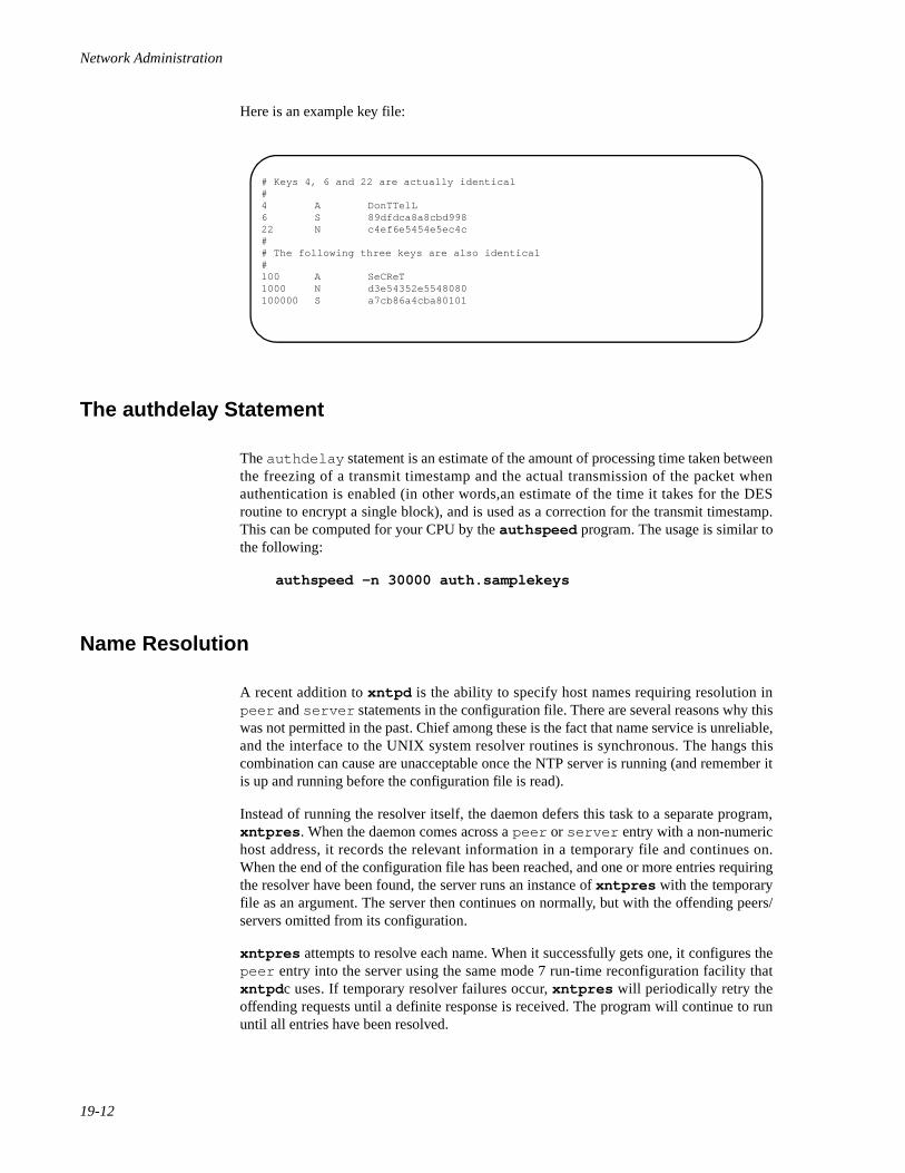
Network Administration
19-12
Here is an example key file:
The authdelay Statement 19
The authdelay statement is an estimate of the amount of processing time taken betweenthe freezing of a transmit timestamp and the actual transmission of the packet whenauthentication is enabled (in other words,an estimate of the time it takes for the DESroutine to encrypt a single block), and is used as a correction for the transmit timestamp.This can be computed for your CPU by the authspeed program. The usage is similar tothe following:
authspeed -n 30000 auth.samplekeys
Name Resolution 19
A recent addition to xntpd is the ability to specify host names requiring resolution inpeer and server statements in the configuration file. There are several reasons why thiswas not permitted in the past. Chief among these is the fact that name service is unreliable,and the interface to the UNIX system resolver routines is synchronous. The hangs thiscombination can cause are unacceptable once the NTP server is running (and remember itis up and running before the configuration file is read).
Instead of running the resolver itself, the daemon defers this task to a separate program,xntpres . When the daemon comes across a peer or server entry with a non-numerichost address, it records the relevant information in a temporary file and continues on.When the end of the configuration file has been reached, and one or more entries requiringthe resolver have been found, the server runs an instance of xntpres with the temporaryfile as an argument. The server then continues on normally, but with the offending peers/servers omitted from its configuration.
xntpres attempts to resolve each name. When it successfully gets one, it configures thepeer entry into the server using the same mode 7 run-time reconfiguration facility thatxntpd c uses. If temporary resolver failures occur, xntpres will periodically retry theoffending requests until a definite response is received. The program will continue to rununtil all entries have been resolved.
# Keys 4, 6 and 22 are actually identical#4 A DonTTelL6 S 89dfdca8a8cbd99822 N c4ef6e5454e5ec4c## The following three keys are also identical#100 A SeCReT1000 N d3e54352e5548080100000 S a7cb86a4cba80101

Network Time Synchronization
19-13
There are several configuration requirements if xntpres is to be used. The path to thexntpres program must be made known to the daemon via a resolver configuration entry,and mode 7 run-time reconfiguration must be enabled. The following fragment might beadded to /etc/inet/ntp.conf to accomplish this:
Note that xntpres sends packets to the server with a source address of 127.0.0.1 .You should obviously avoid restricting modification requests from this address, orxntpres will fail.
Clock Support Overview 19
xntpd was designed to support radio (and other external) clocks and does some parts ofthis function nicely. Clocks are treated by the protocol as favored NTP peers, even to thepoint of referring to them with an (invalid) IP host address. Clock addresses are of theform
127.127. type. unit
where type specifies the particular type of clock (or a particular clock driver), and unit is aunit number whose interpretation is clock driver dependent. This is analogous to the use ofmajor and minor device numbers by the UNIX system.
Because clocks look much like peers, both configuration file syntax and run-timereconfiguration commands can be adopted to control clocks unchanged. Clocks areconfigured via server declarations in the configuration file (peer declarations can alsobe used, but the server form is preferred). Clocks can be started and stopped usingxntpdc , and are subject to address-and-mask restrictions much like a normal peer. As aconcession to the need to sometimes transmit additional information to clock drivers, how-ever, an additional configuration file statement was added, the fudge statement. Thisenables you to specify the values of two time quantities, two integral values and two flags,the use of which is dependent on the particular clock driver the values are being given to.
For example, to configure a PST radio clock which can be accessed through the serialdevice /dev/pst1 , with propagation delays to WWV and WWVH of 7.5 and 26.5milliseconds, respectively, on a machine with an imprecise system clock and with thedriver set to disbelieve the radio clock once it has gone 30 minutes without an update, onemight use the following configuration file entries:
resolver /usr/sbin/xntpreskeys /etc/inet/ntp.keysrequestkey 65535
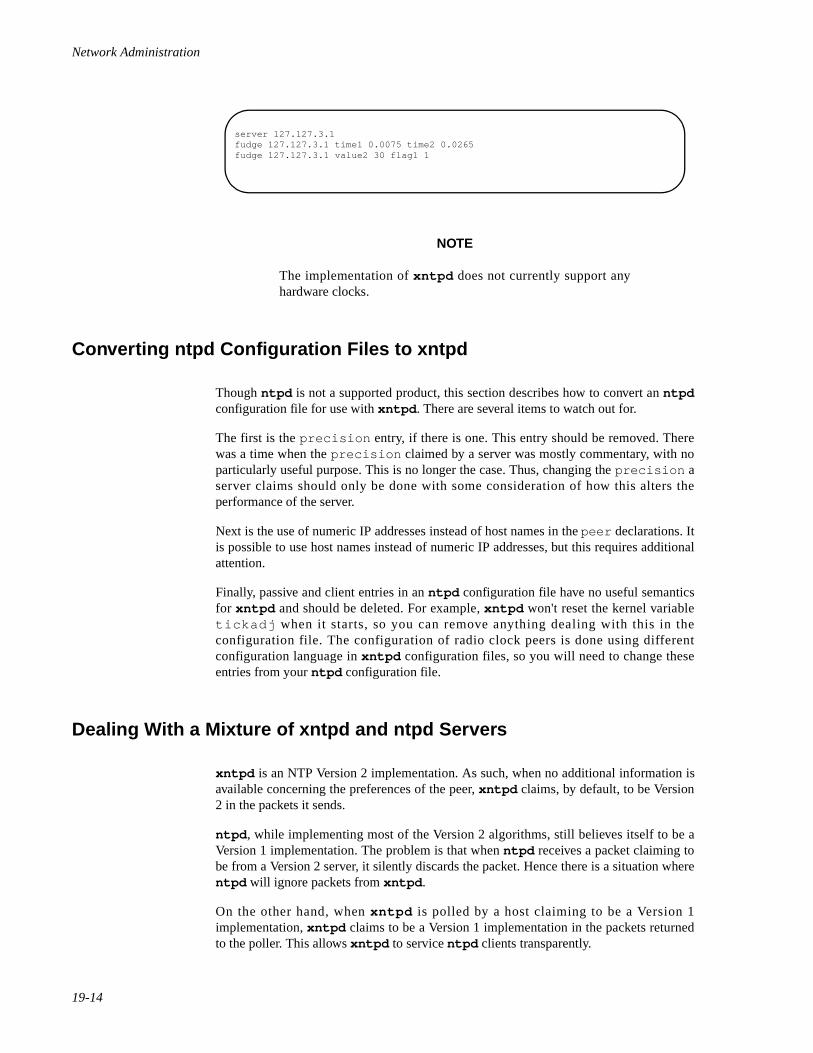
Network Administration
19-14
NOTE
The implementation of xntpd does not currently support anyhardware clocks.
Converting ntpd Configuration Files to xntpd 19
Though ntpd is not a supported product, this section describes how to convert an ntpdconfiguration file for use with xntpd . There are several items to watch out for.
The first is the precision entry, if there is one. This entry should be removed. Therewas a time when the precision claimed by a server was mostly commentary, with noparticularly useful purpose. This is no longer the case. Thus, changing the precision aserver claims should only be done with some consideration of how this alters theperformance of the server.
Next is the use of numeric IP addresses instead of host names in the peer declarations. Itis possible to use host names instead of numeric IP addresses, but this requires additionalattention.
Finally, passive and client entries in an ntpd configuration file have no useful semanticsfor xntpd and should be deleted. For example, xntpd won't reset the kernel variabletickadj when it starts, so you can remove anything dealing with this in theconfiguration file. The configuration of radio clock peers is done using differentconfiguration language in xntpd configuration files, so you will need to change theseentries from your ntpd configuration file.
Dealing With a Mixture of xntpd and ntpd Servers 19
xntpd is an NTP Version 2 implementation. As such, when no additional information isavailable concerning the preferences of the peer, xntpd claims, by default, to be Version2 in the packets it sends.
ntpd , while implementing most of the Version 2 algorithms, still believes itself to be aVersion 1 implementation. The problem is that when ntpd receives a packet claiming tobe from a Version 2 server, it silently discards the packet. Hence there is a situation wherentpd will ignore packets from xntpd .
On the other hand, when xntpd is polled by a host claiming to be a Version 1implementation, xntpd claims to be a Version 1 implementation in the packets returnedto the poller. This allows xntpd to service ntpd clients transparently.
server 127.127.3.1fudge 127.127.3.1 time1 0.0075 time2 0.0265fudge 127.127.3.1 value2 30 flag1 1
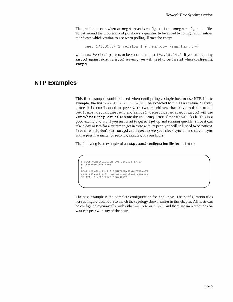
Network Time Synchronization
19-15
The problem occurs when an ntpd server is configured in an xntpd configuration file.To get around the problem, xntpd allows a qualifier to be added to configuration entriesto indicate which version to use when polling. Hence the entry:
peer 192.35.54.2 version 1 # nehd.gov (running ntpd)
will cause Version 1 packets to be sent to the host 192.35.54.2 . If you are runningxntpd against existing ntpd servers, you will need to be careful when configuringxntpd .
NTP Examples 19
This first example would be used when configuring a single host to use NTP. In theexample, the host rainbow.sci.com will be expected to run as a stratum 2 server,s ince i t is configured to peer with two machines that have rad io c locks:bedivere.cs.purdue.edu and asmus1.genetics.uga.edu . xntpd will use/etc/inet/ntp.drift to store the frequency error of rainbow 's clock. This is agood example to use if you just want to get xntpd up and running quickly. Since it cantake a day or two for a system to get in sync with its peer, you will still need to be patient.In other words, don't start xntpd and expect to see your clock sync up and stay in syncwith a peer in a matter of seconds, minutes, or even hours.
The following is an example of an ntp.conf configuration file for rainbow :
The next example is the complete configuration for sci.com . The configuration fileshere configure sci.com to match the topology shown earlier in this chapter. All hosts canbe configured dynamically with either xntpdc or ntpq . And there are no restrictions onwho can peer with any of the hosts.
# Peer configuration for 128.212.66.13# (rainbow.sci.com)#peer 128.211.1.24 # bedivere.cs.purdue.edupeer 128.192.8.4 # asmus1.genetics.uga.edudriftfile /etc/inet/ntp.drift
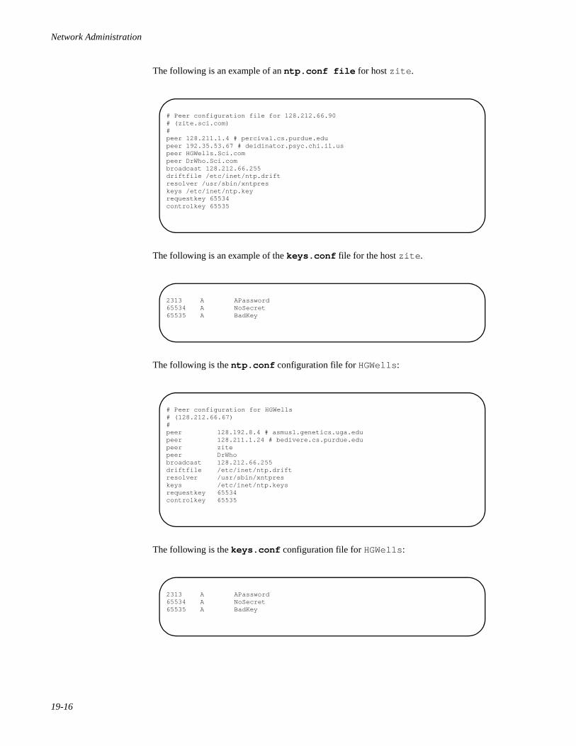
Network Administration
19-16
The following is an example of an ntp.conf file for host zite .
The following is an example of the keys.conf file for the host zite .
The following is the ntp.conf configuration file for HGWells :
The following is the keys.conf configuration file for HGWells :
# Peer configuration file for 128.212.66.90# (zite.sci.com)#peer 128.211.1.4 # percival.cs.purdue.edupeer 192.35.53.67 # deidinator.psyc.chi.il.uspeer HGWells.Sci.compeer DrWho.Sci.combroadcast 128.212.66.255driftfile /etc/inet/ntp.driftresolver /usr/sbin/xntpreskeys /etc/inet/ntp.keyrequestkey 65534controlkey 65535
2313 A APassword65534 A NoSecret65535 A BadKey
# Peer configuration for HGWells# (128.212.66.67)#peer 128.192.8.4 # asmus1.genetics.uga.edupeer 128.211.1.24 # bedivere.cs.purdue.edupeer zitepeer DrWhobroadcast 128.212.66.255driftfile /etc/inet/ntp.driftresolver /usr/sbin/xntpreskeys /etc/inet/ntp.keysrequestkey 65534controlkey 65535
2313 A APassword65534 A NoSecret65535 A BadKey
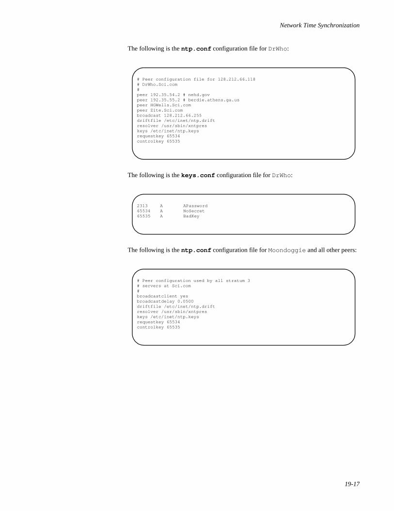
Network Time Synchronization
19-17
The following is the ntp.conf configuration file for DrWho:
The following is the keys.conf configuration file for DrWho:
The following is the ntp.conf configuration file for Moondoggie and all other peers:
# Peer configuration file for 128.212.66.118# DrWho.Sci.com#peer 192.35.54.2 # nehd.govpeer 192.35.55.2 # berdie.athens.ga.uspeer HGWells.Sci.compeer Zite.Sci.combroadcast 128.212.66.255driftfile /etc/inet/ntp.driftresolver /usr/sbin/xntpreskeys /etc/inet/ntp.keysrequestkey 65534controlkey 65535
2313 A APassword65534 A NoSecret65535 A BadKey
# Peer configuration used by all stratum 3# servers at Sci.com#broadcastclient yesbroadcastdelay 0.0500driftfile /etc/inet/ntp.driftresolver /usr/sbin/xntpreskeys /etc/inet/ntp.keysrequestkey 65534controlkey 65535
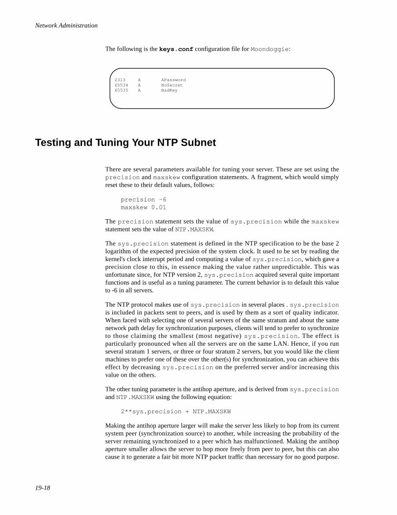
Network Administration
19-18
The following is the keys.conf configuration file for Moondoggie :
Testing and Tuning Your NTP Subnet 19
There are several parameters available for tuning your server. These are set using theprecision and maxskew configuration statements. A fragment, which would simplyreset these to their default values, follows:
precision -6maxskew 0.01
The precision statement sets the value of sys.precision while the maxskewstatement sets the value of NTP.MAXSKW.
The sys.precision statement is defined in the NTP specification to be the base 2logarithm of the expected precision of the system clock. It used to be set by reading thekernel's clock interrupt period and computing a value of sys.precision , which gave aprecision close to this, in essence making the value rather unpredictable. This wasunfortunate since, for NTP version 2, sys.precision acquired several quite importantfunctions and is useful as a tuning parameter. The current behavior is to default this valueto -6 in all servers.
The NTP protocol makes use of sys.precision in several places . sys.precisionis included in packets sent to peers, and is used by them as a sort of quality indicator.When faced with selecting one of several servers of the same stratum and about the samenetwork path delay for synchronization purposes, clients will tend to prefer to synchronizeto those claiming the smallest (most negative) sys.precision . The effect isparticularly pronounced when all the servers are on the same LAN. Hence, if you runseveral stratum 1 servers, or three or four stratum 2 servers, but you would like the clientmachines to prefer one of these over the other(s) for synchronization, you can achieve thiseffect by decreasing sys.precision on the preferred server and/or increasing thisvalue on the others.
The other tuning parameter is the antihop aperture, and is derived from sys.precisionand NTP.MAXSKW using the following equation:
2**sys.precision + NTP.MAXSKW
Making the antihop aperture larger will make the server less likely to hop from its currentsystem peer (synchronization source) to another, while increasing the probability of theserver remaining synchronized to a peer which has malfunctioned. Making the antihopaperture smaller allows the server to hop more freely from peer to peer, but this can alsocause it to generate a fair bit more NTP packet traffic than necessary for no good purpose.
2313 A APassword65534 A NoSecret65535 A BadKey
Network Time Synchronization
19-19
Given the agreement among current stratum 1 NTP servers and the performance typical ofthe Internet, it is recommended that the antihop aperture be maintained with a value ofbetween 0.020 and 0.030 (if you calculate the default value you will find it is about 0.026).You can change the antihop aperture by changing the value of NTP.MAXSKW via amaxskew configuration statement. Note, however, that if you wish to changesys.precision via a precision configuration statement, but don't wish to alter theantihop aperture, you must change NTP.MAXSKW to compensate.
Related xntp Commands 19
Two separate query programs are included with the xntp distribution: ntpq andxntpdc .
ntpq sends queries and receives responses using NTP standard mode 6 control messages.Since it uses the standard query protocol, it may be used to query the NTP servers as wellas xntpd .
xntpdc is a program which uses NTP private mode 7 messages to make requests to theserver. The format and content of these messages are specific to xntpd . The programallows inspection of a wide variety of internal counters and other state data. xntpdc alsoprovides a user interface to the run-time reconfiguration facility.
Both of these programs are nonessential to the operation of xntpd . The main reason fordescribing them here is to point out an important inconsistency. Both xntpdc and xntpddemand that anything which has dimensions of time be specified in units of seconds, bothin the configuration file and when doing run-time reconfiguration. Both programs alsoprint the values in seconds. ntpq , on the other hand, obeys the standard by printing alltime values in milliseconds. This makes the process of looking at values with ntpq , andthen changing them in the configuration file or with xntpdc , very prone to errors (bythree orders of magnitude).
xntpd was written specifically to allow its configuration to be fully modifiable at runtime. Indeed, the only way to configure the server is at run time. The configuration file isread only after the rest of the server has been initialized into a running, but defaultunconfigured, state. This facility was included not so much for the benefit of the UNIXsystem, where it is handy but not strictly essential, but rather for limited platforms wherethe feature is more important for maintenance. Nevertheless, run-time configuration worksvery nicely for UNIX servers as well.
Nearly all of the things it is possible to configure in the configuration file may be alteredvia NTP mode 7 messages using the xntpdc program. Mode 6 messages may alsoprovide some limited configuration functionality (though the only thing you can currentlydo with mode 6 messages is set the leap second warning bits) and the ntpq programprovides generic support for the latter.
Mode 6 and mode 7 messages which would modify the configuration of the server arerequired to be authenticated using standard NTP authentication. To enable the facilitiesyou must, in addition to specifying the location of a keys file, indicate in theconfiguration file, the key IDs to be used for authenticating reconfiguration requests.Hence, the following fragment might be added to a configuration file to enable the mode 6(ntpq ) and mode 7 (xntpdc ) facilities in the daemon:
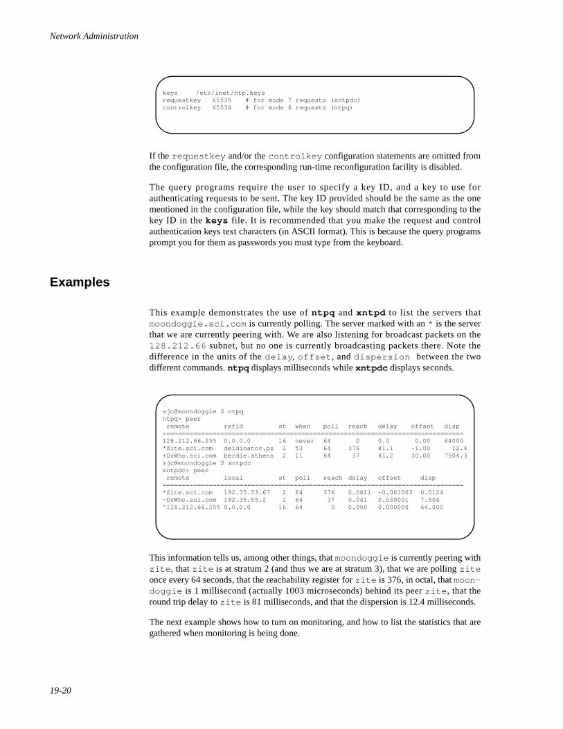
Network Administration
19-20
If the requestkey and/or the controlkey configuration statements are omitted fromthe configuration file, the corresponding run-time reconfiguration facility is disabled.
The query programs require the user to specify a key ID, and a key to use forauthenticating requests to be sent. The key ID provided should be the same as the onementioned in the configuration file, while the key should match that corresponding to thekey ID in the keys file. It is recommended that you make the request and controlauthentication keys text characters (in ASCII format). This is because the query programsprompt you for them as passwords you must type from the keyboard.
Examples 19
This example demonstrates the use of ntpq and xntpd to list the servers thatmoondoggie.sci.com is currently polling. The server marked with an * is the serverthat we are currently peering with. We are also listening for broadcast packets on the128.212.66 subnet, but no one is currently broadcasting packets there. Note thedifference in the units of the delay , offset , and dispersion between the twodifferent commands. ntpq displays milliseconds while xntpdc displays seconds.
This information tells us, among other things, that moondoggie is currently peering withzite , that zite is at stratum 2 (and thus we are at stratum 3), that we are polling ziteonce every 64 seconds, that the reachability register for zite is 376, in octal, that moon-doggie is 1 millisecond (actually 1003 microseconds) behind its peer zite , that theround trip delay to zite is 81 milliseconds, and that the dispersion is 12.4 milliseconds.
The next example shows how to turn on monitoring, and how to list the statistics that aregathered when monitoring is being done.
keys /etc/inet/ntp.keysrequestkey 65535 # for mode 7 requests (xntpdc)controlkey 65534 # for mode 6 requests (ntpq)
sjc@moondoggie $ ntpqntpq> peer remote refid st when poll reach delay offset disp==============================================================================128.212.66.255 0.0.0.0 16 never 64 0 0.0 0.00 64000*Zite.sci.com deidinator.ps 2 53 64 376 81.1 -1.00 12.4+DrWho.sci.com berdie.athens 2 11 64 37 41.2 30.00 7504.3sjc@moondoggie $ xntpdcxntpdc> peer remote local st poll reach delay offset disp==============================================================================*Zite.sci.com 192.35.53.67 2 64 376 0.0811 -0.001003 0.0124-DrWho.sci.com 192.35.55.2 2 64 37 0.041 0.030001 7.504^128.212.66.255 0.0.0.0 16 64 0 0.000 0.000000 64.000
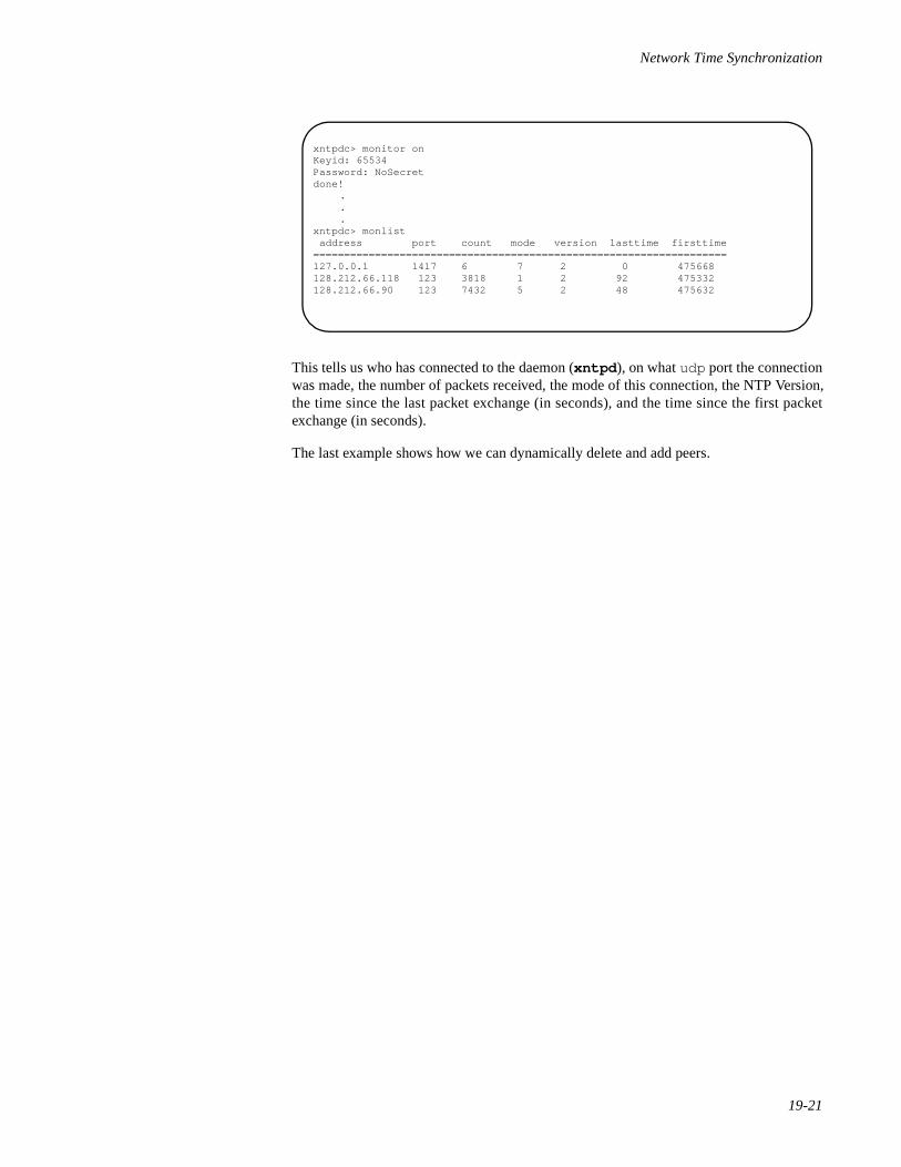
Network Time Synchronization
19-21
This tells us who has connected to the daemon (xntpd ), on what udp port the connectionwas made, the number of packets received, the mode of this connection, the NTP Version,the time since the last packet exchange (in seconds), and the time since the first packetexchange (in seconds).
The last example shows how we can dynamically delete and add peers.
xntpdc> monitor onKeyid: 65534Password: NoSecretdone!
.
.
.xntpdc> monlist address port count mode version lasttime firsttime===================================================================127.0.0.1 1417 6 7 2 0 475668128.212.66.118 123 3818 1 2 92 475332128.212.66.90 123 7432 5 2 48 475632
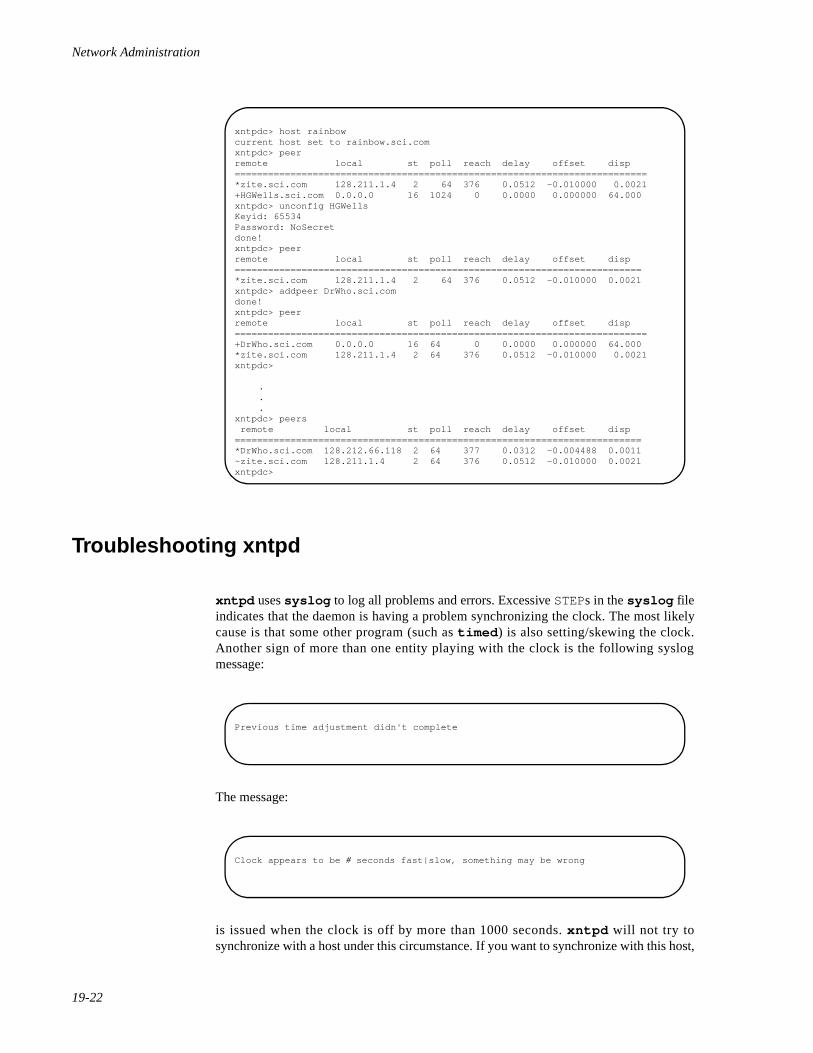
Network Administration
19-22
Troubleshooting xntpd 19
xntpd uses syslog to log all problems and errors. Excessive STEPs in the syslog fileindicates that the daemon is having a problem synchronizing the clock. The most likelycause is that some other program (such as timed ) is also setting/skewing the clock.Another sign of more than one entity playing with the clock is the following syslogmessage:
The message:
is issued when the clock is off by more than 1000 seconds. xntpd will not try tosynchronize with a host under this circumstance. If you want to synchronize with this host,
xntpdc> host rainbowcurrent host set to rainbow.sci.comxntpdc> peerremote local st poll reach delay offset disp==========================================================================*zite.sci.com 128.211.1.4 2 64 376 0.0512 -0.010000 0.0021+HGWells.sci.com 0.0.0.0 16 1024 0 0.0000 0.000000 64.000xntpdc> unconfig HGWellsKeyid: 65534Password: NoSecretdone!xntpdc> peerremote local st poll reach delay offset disp=========================================================================*zite.sci.com 128.211.1.4 2 64 376 0.0512 -0.010000 0.0021xntpdc> addpeer DrWho.sci.comdone!xntpdc> peerremote local st poll reach delay offset disp==========================================================================+DrWho.sci.com 0.0.0.0 16 64 0 0.0000 0.000000 64.000*zite.sci.com 128.211.1.4 2 64 376 0.0512 -0.010000 0.0021xntpdc>
.
.
.xntpdc> peers remote local st poll reach delay offset disp=========================================================================*DrWho.sci.com 128.212.66.118 2 64 377 0.0312 -0.004488 0.0011~zite.sci.com 128.211.1.4 2 64 376 0.0512 -0.010000 0.0021xntpdc>
Previous time adjustment didn't complete
Clock appears to be # seconds fast|slow, something may be wrong
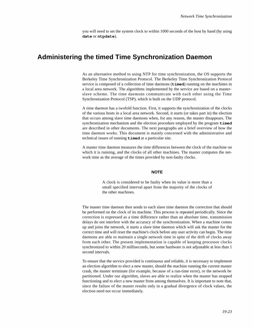
Network Time Synchronization
19-23
you will need to set the system clock to within 1000 seconds of the host by hand (by usingdate or ntpdate ).
Administering the timed Time Synchronization Daemon 19
As an alternative method to using NTP for time synchronization, the OS supports theBerkeley Time Synchronization Protocol. The Berkeley Time Synchronization Protocolservice is composed of a collection of time daemons (timed ) running on the machines ina local area network. The algorithms implemented by the service are based on a master-slave scheme. The time daemons communicate with each other using the TimeSynchronization Protocol (TSP), which is built on the UDP protocol.
A time daemon has a twofold function. First, it supports the synchronization of the clocksof the various hosts in a local area network. Second, it starts (or takes part in) the electionthat occurs among slave time daemons when, for any reason, the master disappears. Thesynchronization mechanism and the election procedure employed by the program timedare described in other documents. The next paragraphs are a brief overview of how thetime daemon works. This document is mainly concerned with the administrative andtechnical issues of running timed at a particular site.
A master time daemon measures the time differences between the clock of the machine onwhich it is running, and the clocks of all other machines. The master computes the net-work time as the average of the times provided by non-faulty clocks.
NOTE
A clock is considered to be faulty when its value is more than asmall specified interval apart from the majority of the clocks ofthe other machines.
The master time daemon then sends to each slave time daemon the correction that shouldbe performed on the clock of its machine. This process is repeated periodically. Since thecorrection is expressed as a time difference rather than an absolute time, transmissiondelays do not interfere with the accuracy of the synchronization. When a machine comesup and joins the network, it starts a slave time daemon which will ask the master for thecorrect time and will reset the machine's clock before any user activity can begin. The timedaemons are able to maintain a single network time in spite of the drift of clocks awayfrom each other. The present implementation is capable of keeping processor clockssynchronized to within 20 milliseconds, but some hardware is not adjustable at less than 1second intervals.
To ensure that the service provided is continuous and reliable, it is necessary to implementan election algorithm to elect a new master, should the machine running the current mastercrash, the master terminate (for example, because of a run-time error), or the network bepartitioned. Under our algorithm, slaves are able to realize when the master has stoppedfunctioning and to elect a new master from among themselves. It is important to note that,since the failure of the master results only in a gradual divergence of clock values, theelection need not occur immediately.
Network Administration
19-24
The machines that are gateways between distinct local area networks require particularcare. A time daemon on such machines may act as a submaster. This artifact depends onthe current inability of transmission protocols to broadcast a message on a network otherthan the one to which the broadcasting machine is connected. The submaster appears as aslave on one network, and as a master on one or more of the other networks to which it isconnected.
A submaster classifies each network as one of three types. A slave network is a network onwhich the submaster acts as a slave. There can only be one slave network. A master net-work is a network on which the submaster acts as a master. An ignored network is anyother network which already has a valid master. The submaster tries periodically tobecome master on an ignored network, but gives up immediately if a master already exists.
Guidelines 19
While the synchronization algorithm is quite general, the election algorithm, requiring abroadcast mechanism, puts constraints on the kind of network on which time daemons canrun. The time daemon will only work on networks with broadcast capability augmentedwith point-to-point links. Machines that are only connected to point-to-point, non-broad-cast networks, may not use the time daemon.
If we exclude submasters, there will normally be, at most, one master time daemon in alocal area internetwork. During an election, only one of the slave time daemons willbecome the new master. However, because of the characteristics of its machine, a slavecan be prevented from becoming the master. Therefore, a subset of machines must bedesignated as potential master time daemons. A master time daemon will require CPUresources proportional to the number of slaves, in general, more than a slave time daemon,so it may be advisable to limit master time daemons to machines with more powerfulprocessors or lighter loads. Also, machines with inaccurate clocks should not be used asmasters. This is a purely administrative decision; an organization may well allow all of itsmachines to run master time daemons.
At the administrative level, a time daemon on a machine with multiple network interfacesmay be told to ignore all but one network, or to ignore one network. This is done with the-n network and -i network options, respectively, at start-up time. Typically, the timedaemon would be instructed to ignore all but the networks belonging to the localadministrative control.
There are some limitations to the current implementation of the time daemon. Forexample, the maximum number of machines that may be directly controlled by one mastertime daemon is fixed at 99.
In addition, there is a pathological situation to be avoided at all costs, that might occurwhen time daemons run on multiply-connected local area networks. In this case, as wehave seen, time daemons running on gateway machines will be submasters, and they willact on some of those networks as master time daemons. For example, consider machines Aand B that are both gateways between networks X and Y. If time daemons were started onboth A and B without constraints, it would be possible for submaster time daemon A to bea slave on network X and the master on network Y, while submaster time daemon B is aslave on network Y and the master on network X. This loop of master time daemons willnot function properly or guarantee a unique time on both networks, and will cause the sub-
Network Time Synchronization
19-25
masters to use large amounts of system resources in the form of network bandwidth andCPU time. In fact, this kind of loop can also be generated with more than two master timedaemons, when several local area networks are interconnected.
Options 19
The flags are:
-n network consider the named network
-i network ignore the named network
-t place tracing information in /usr/adm/timed.log
-M allow this time daemon to become a master (a time daemon runwithout this option will be forced into the state of slave during anelection)
Daily Operation 19
The timedc command is used to control the operation of the time daemon. timedc maybe used to:
• measure the differences between clocks on different machines
• find the location where the master timed is running
• cause election timers on several machines to expire at the same time
• enable or disable tracing of messages received by timed
See the timed(1M) and timedc(1M) manual pages for more detailed information.Note that the netdate(1M) command can be used to set the network date.

Network Administration
19-26

-27
4Part 4Distributed File System Administration
Replace with Part 4 tab

Network Administration
-28
20Introduction to DFS Administration
About DFS Administration . . . . . . . . . . . . . . . . . . . . . . . . . . . . . . . . . . . . . . . . . . . . 20-1Organization . . . . . . . . . . . . . . . . . . . . . . . . . . . . . . . . . . . . . . . . . . . . . . . . . . . . 20-1
File Sharing . . . . . . . . . . . . . . . . . . . . . . . . . . . . . . . . . . . . . . . . . . . . . . . . . . . . . . . . 20-2An Overview of DFS Administration . . . . . . . . . . . . . . . . . . . . . . . . . . . . . . . . . . . . 20-3
DFS Commands and Files . . . . . . . . . . . . . . . . . . . . . . . . . . . . . . . . . . . . . . . . . 20-3

Network Administration
20-1
20Chapter 20Introduction to DFS Administration
202020
About DFS Administration 20
The DFS Administration chapters, “Introduction to DFS Administration”, “Setting UpDFS”, “Using DFS Commands and Files” and “DFS sysadm Interface”, describe the tasksyou can perform using Distributed File System Administration—a set of commands andfiles that allows you to administer NFS (as well as other distributed file system types thatmay be available in the future) in a consistent way. The files and commands that supportcommon administration of NFS are provided in the Distributed File System (DFS)Administration Utilities package.
Organization 20
The DFS Administration chapters are organized by the tasks that can be performed usingDFS Administration commands and files.
In addition to the command line interface, a menu interface is provided through which youcan enter DFS commands. The menus are included with System Administration Menus(sysadm ), a menu-based administration interface that is standard with the OS. Once youaccess a sysadm menu, help screens provide you with all the information you need tocomplete a task. Therefore, the “DFS sysadm Interface” chapter does not lead you step-by-step through the menu-based procedures. Instead, it documents DFS commands as youwould enter them at the command line. This chapter describes the DFS menus and directsyou to “Using the sysadm Interface” in the System Administration guide for instruction inusing the menu interface.
The organization of the DFS Administration chapters are as follows:
• “Introduction to DFS Administration” presents an overview of DFSAdministration, and describes all the commands and files that theDistributed File System Administration Utilities package either installs orutilizes.
• “Setting Up DFS” describes the software that must be installed before youcan use DFS Administration and directs you to installation instructions.
• “Using DFS Commands and Files” tells you how to share and unshare filesystem resources using DFS commands and files; how to mount andunmount remote resources; and how to display information about resourcesthat are shared and mounted on your local system and on network clients.
• “DFS sysadm Interface”, describes the System Administration Menu(sysadm ) interface to DFS Administration.
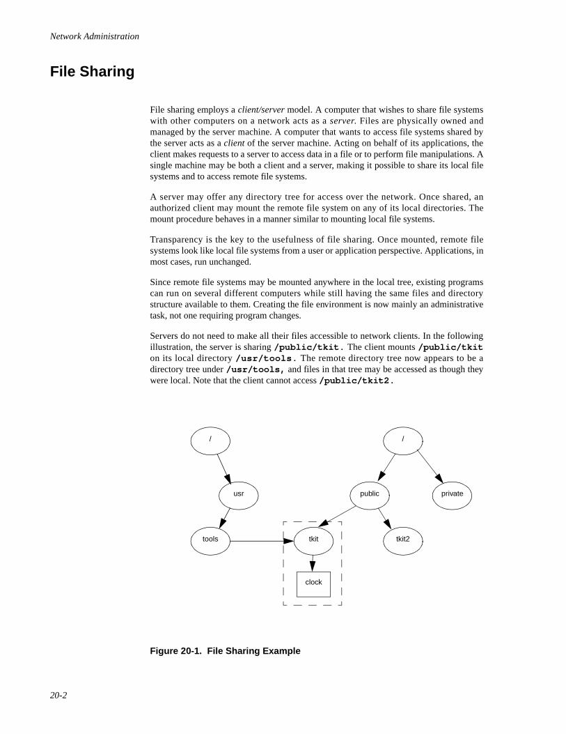
Network Administration
20-2
File Sharing 20
File sharing employs a client/server model. A computer that wishes to share file systemswith other computers on a network acts as a server. Files are physically owned andmanaged by the server machine. A computer that wants to access file systems shared bythe server acts as a client of the server machine. Acting on behalf of its applications, theclient makes requests to a server to access data in a file or to perform file manipulations. Asingle machine may be both a client and a server, making it possible to share its local filesystems and to access remote file systems.
A server may offer any directory tree for access over the network. Once shared, anauthorized client may mount the remote file system on any of its local directories. Themount procedure behaves in a manner similar to mounting local file systems.
Transparency is the key to the usefulness of file sharing. Once mounted, remote filesystems look like local file systems from a user or application perspective. Applications, inmost cases, run unchanged.
Since remote file systems may be mounted anywhere in the local tree, existing programscan run on several different computers while still having the same files and directorystructure available to them. Creating the file environment is now mainly an administrativetask, not one requiring program changes.
Servers do not need to make all their files accessible to network clients. In the followingillustration, the server is sharing /public/tkit. The client mounts /public/tkiton its local directory /usr/tools. The remote directory tree now appears to be adirectory tree under /usr/tools, and files in that tree may be accessed as though theywere local. Note that the client cannot access /public/tkit2.
Figure 20-1. File Sharing Example
/
usr
tkittools tkit2
public
/
private
clock
Introduction to DFS Administration
20-3
In a file sharing environment, a large number of users can access a program as though itwere on their local machines, when actually the program resides on a single file server.This is a great benefit to small workstations, where disk space is at a premium. A user canhave access to a much larger program repertoire than could fit on a private disk.
By having a resource reside physically on a single server, then distributed throughout thenetwork, you can greatly simplify administration. First, you reduce the number of copiesof various programs that need to be maintained on the network. Second, you reduce theproblems involved in performing backups for a number of machines dispersed over a widegeographical area. By keeping files in a single location, this task becomes comparable tobacking up a single machine.
Centralizing files on a few file servers not only simplifies administration, it helps maintainconsistency of shared data files. When changes are made to a shared file, they becomeavailable to all users immediately.
As an alternative to centralizing files on a few file servers, files may be shared in a peermanner. When a single computer runs out of capacity, more computers can be added to aconfiguration. Files can be moved to the new computers, while a consistent view of the filesystem from the user's perspective is maintained.
An Overview of DFS Administration 20
Some tasks involved in the administration of a distributed file system package are thesame, whether you are using NFS or some other file system package. The Virtual FileSystem architecture provides a mechanism for administering file system types in ageneral, or generic, way. Administrators of NFS or other file system types are providedwith a common set of commands which can be used to administer NFS (as well as anydistributed file system type that may be supported in the future).
For example, to share a resource on your computer with remote systems, you must makethe resource available and communicate its availability. To make a local resource availablerunning earlier versions of NFS, you would “export” it, using the exportfs command. Ifyou were to run another distributed file system package, keeping the corresponding pack-age-specific commands straight might be difficult. Multiply this by the number of corre-sponding package-specific commands in both packages, and the job becomes even moredifficult.
DFS Administration provides generic commands that call package-specific commands,freeing you of the need to learn two sets of corresponding commands.
DFS Commands and Files 20
The DFS Administration Utilities package installs seven commands: share , unshare ,shareall , unshareall , dfshares , and dfmounts . In addition to these commands,DFS Administration utilizes a number of files and commands installed by the otherpackages.
Network Administration
20-4
All the files and commands relevant to DFS administration are described in this section.Files and commands that operate on all file system types are described in this section onlyas they relate to administering distributed file systems.
The DFS Administration files are:
• /etc/dfs/fstypes , which is used to register the distributed file systempackages you have installed on your system and establishes the defaultpackage (the first line in this file is the default package). The fstypes fileis created by the distributed file system package you install first.
• /etc/dfs/dfstab , which allows you to share a resource or a set ofresources automatically when you enter system state 3.
• /etc/vfstab , which allows you to mount resources automatically whenyou enter system state 3.
• /etc/dfs/sharetab , which logs the resources currently shared onyour system. The sharetab file is created by the share command anddoes not require handling by an administrator.
• /etc/mnttab , which logs the file systems currently mounted by yoursystem, including remote file systems and directories. The mnttab file iscreated by the mount command and does not require handling by anadministrator.
DFS Administration commands are:
• share(1M), which allows you to make a resource available for mountingby clients, or to display a list of the resources on your system that arecurrently shared.
• unshare(1M), which allows you to make a previously availableresource unavailable for mounting by clients.
• shareall(1M) , which executes a script that shares a pre-determined setof resources, listed in /etc/dfs/dfstab .
• unshareall [see shareall(1M)] , which executes a script thatunshares all currently shared resources, listed in /etc/dfs/dfstab .
• mount(1M) , which allows you to mount a remote resource on yoursystem, or to display a list of resources, both local and remote, that arecurrently mounted on your system.
• umount [see mount(1M) ], which allows you to remove a remoteresource you previously mounted.
• mountall(1M) , which executes a script that mounts a pre-determined setof resources.
• umountall [see mountall(1M)], which executes a script thatunmounts all currently mounted resources.
• dfshares(1M) , which displays a list of remote resources that areavailable to you, as well as a list of local resources that are currentlyshared.

Introduction to DFS Administration
20-5
• dfmounts(1M), which shows you which local resources are mounted bywhich clients.

Network Administration
20-6
21Setting Up DFS
Introduction to DFS Setup. . . . . . . . . . . . . . . . . . . . . . . . . . . . . . . . . . . . . . . . . . . . . 21-1Installing the Software. . . . . . . . . . . . . . . . . . . . . . . . . . . . . . . . . . . . . . . . . . . . . . . . 21-1Logging in As the Network Administrator . . . . . . . . . . . . . . . . . . . . . . . . . . . . . . . . 21-1
Assigning the NET Role. . . . . . . . . . . . . . . . . . . . . . . . . . . . . . . . . . . . . . . . . . . 21-2Defining Additional Roles . . . . . . . . . . . . . . . . . . . . . . . . . . . . . . . . . . . . . . . . . 21-3
Changing the File Sharing Package Default . . . . . . . . . . . . . . . . . . . . . . . . . . . . . . . 21-3Starting Distributed File System Operation. . . . . . . . . . . . . . . . . . . . . . . . . . . . . . . . 21-4

Network Administration
21-1
21Chapter 21Setting Up DFS
212121
Introduction to DFS Setup 21
This chapter describes the tasks you must complete before you execute DFSAdministration commands. These tasks are installing the software, possibly editing a fileto establish a default file sharing package, and starting distributed file system operation.
Installing the Software 21
If you installed all the software when you received the operating system, DFSAdministration is already installed on your system. If you did not install all the add-onutilities, you'll need to install DFS Administration Utilities, as well as NFS Utilities and allthe hardware and software required to run NFS.
Installation instructions for all operating system software—including DFS AdministrationUtilities and NFS Utilities—appear in the Release Notes. Hardware and softwareprerequisites for NFS appear in Chapter 25, "Setting Up NFS".
Once all your network hardware and software are installed, you must set up your filesharing packages before you can enter DFS commands.
Logging in As the Network Administrator 21
If the Enhanced Security Utilities are installed, the role of the superuser is divided intomultiple roles, each with the authority to perform specific administrative tasks. There nolonger exists a single login that allows a user to override all system restrictions andperform any task associated with system administration or maintenance.
In place of the superuser, the Enhanced Security Utilities provide five distinctadministrative roles, each with responsibility for a certain aspect of the system. Each roleis associated with the commands and privileges required to complete the relevantadministrative tasks. Logins are then created and assigned an administrative role.
The database that associates commands with roles is the Trusted Facility Management(TFM) database. A command entry in the database includes an alias for the command, thepath to the executable file, and the privileges to be granted to an authorized user. A useridentified in the database as an administrator can execute the command with the privileges
Network Administration
21-2
listed. To execute the command, however, the user must preface it with tfadmin. Forexample, to shut down the system, a user must access the system using a login associatedwith the appropriate administrative role and enter the following command:
tfadmin shutdown -g0 -y -i6
The role with responsibility for network administration is NET. Before you can use any ofthe commands associated with DFS or NFS, you must create a login and assign it theadministrative role NET. Once the login has been created, you must access the systemusing that login, then include tfadmin on every DFS or NFS command line.
NOTE
For convenience, tfadmin does not appear in command lineexamples throughout this guide.
In addition to the roles pre-defined on the system, Trusted Facility Management provides aprivileged user with the ability to define other administrative roles. If you choose, you candivide network administration among several people in your organization. For example,you may want to have one person responsible for BNU, and another responsible fordistributed file systems. Using TFM commands, you can create a BNU administrative roleand a DFS administrative role, then assign each role to a different login.
The following section tells you how to assign the NET role to a user login, and how todefine additional administrative roles.
For more information about Trusted Facility Management and administrative roles ingeneral, see the chapter “Trusted Facility Management” in the System Administrationguide.
Assigning the NET Role 21
To assign a role to a user login, you enter the adminuser command with the followingsyntax:
adminuser [ -n ] -o role user
The -n option indicates that the user does not exist as yet in the TFM database. If anexisting entry assigns a different role to the same user login, omit the -n option.
Assume you want to assign the NET role to the login netadmin. If netadmin has noentries in the database, enter the following:
adminuser -n -o NET netadmin
If you want to verify that NET is assigned to netadmin, enter the following.
adminuser netadmin
Now, to set up distributed file system operation, you would log out and log in again asnetadmin.
Setting Up DFS
21-3
Defining Additional Roles 21
If you want to divide responsibility for network administration among several users, youcan create additional administrative roles and associate commands with each role. Forexample, you may want to create a role that has responsibili ty only for NFSadministration. To create a role and associate commands with the role, you need tobecome root in single-user mode. Then you enter the adminrole command with thefollowing syntax:
adminrole -n -a cmd:path[:priv[:priv]][, . . . ] role
The -n option indicates that role is a new administrative role.
Let's call the NFS administrative role nfsadmin. When you create the nfsadmin role,you'll need to associate all the NFS commands with it. The following command linecreates the role and associates the command nfstart and nfstop with the role:
adminrole -n -a nfstart:/usr/sbin/nfstart:allprivs,\ nfstop:/usr/sbin/nfstop:allprivs nfsadmin
To assign additional NFS commands to nfsadmin, enter the adminrole commandagain, omitting the -n option, as in the following command line:
adminrole -a dname:/usr/sbin/dname:allprivs nfsadmin
After you associated all the NFS commands with the NFS administrative role, you need tocreate a login and assign it the nfsadmin role. To assign the role to a login, you use theadminuser command, as described in the previous section. For example, if you want toassign the role to the login mike, you would enter the following:
adminuser -n -o nfsadmin mike
Once you've assigned nfsadmin to the login mike, a user can log in as mike and set upNFS.
Changing the File Sharing Package Default 21
So that the system can distinguish between local and remote file system types, thedistributed file system packages you have installed must be “registered.” When you installNFS, the installation script creates the fstypes file and populates it. If the file alreadyexists when you install the package, the installation script adds a line to the file:
nfs Network File System Utilities: Version number
where number indicates the version number of the package installed.
The package indicated in the first line of the file becomes your default file sharing pack-age. If you enter DFS Administration commands without specifying a package (or filesystem type), the system assumes the first entry in the /etc/dfs/fstypes file. There-fore, if you know that you will administer one package more frequently than the other,
Network Administration
21-4
make that the first entry in the file. This saves you from specifying the package every timeyou enter a DFS command.
To change the default package, edit the file using any supported text editor.
Starting Distributed File System Operation 21
NFS normally becomes operational automatically whenever you take your system to initstate 3; however, NFS can be started in other run levels by entering commands at thecommand prompt.
To start NFS automatically, use the init command to take your system to init state 3. Ifyou choose, you can have your system enter init state 3 automatically when you boot bychanging the initdefault line in the /etc/inittab file to read:
is:3:initdefault:
As explained earlier, DFS Administration allows you to share and mount resources explic-itly, by entering commands at the command line, and automatically, by editing files thatshare and mount resources when you take the system to init state 3. Commands can beentered explicitly in any init state once you start distributed file system operation.Automatic sharing and mounting is done only when your system enters init state 3. Whenyou exit init state 3, any resource you shared is automatically unshared, and any remoteresource you mounted is automatically unmounted.
22Using DFS Commands and Files
Sharing and Unsharing Resources. . . . . . . . . . . . . . . . . . . . . . . . . . . . . . . . . . . . . . . 22-1Sharing a Resource Explicitly—the share Command . . . . . . . . . . . . . . . . . . . . 22-1
Example. . . . . . . . . . . . . . . . . . . . . . . . . . . . . . . . . . . . . . . . . . . . . . . . . . . . 22-1Sharing a Resource Automatically—the /etc/dfs/dfstab File . . . . . . . . . . . . . . . 22-2
Example. . . . . . . . . . . . . . . . . . . . . . . . . . . . . . . . . . . . . . . . . . . . . . . . . . . . 22-2Unsharing a Resource—the unshare Command. . . . . . . . . . . . . . . . . . . . . . . . . 22-2
Example. . . . . . . . . . . . . . . . . . . . . . . . . . . . . . . . . . . . . . . . . . . . . . . . . . . . 22-3Sharing a Set of Resources—the shareall Command. . . . . . . . . . . . . . . . . . . . . 22-3
Example. . . . . . . . . . . . . . . . . . . . . . . . . . . . . . . . . . . . . . . . . . . . . . . . . . . . 22-3Unsharing a Set of Resources—the unshareall Command. . . . . . . . . . . . . . . . . 22-4
Example. . . . . . . . . . . . . . . . . . . . . . . . . . . . . . . . . . . . . . . . . . . . . . . . . . . . 22-4Mounting and Unmounting Remote Resources. . . . . . . . . . . . . . . . . . . . . . . . . . . . . 22-4
Mounting a Remote Resource Explicitly—the mount Command . . . . . . . . . . . 22-5Example 1 . . . . . . . . . . . . . . . . . . . . . . . . . . . . . . . . . . . . . . . . . . . . . . . . . . 22-5Example 2 . . . . . . . . . . . . . . . . . . . . . . . . . . . . . . . . . . . . . . . . . . . . . . . . . . 22-5Example 3 . . . . . . . . . . . . . . . . . . . . . . . . . . . . . . . . . . . . . . . . . . . . . . . . . . 22-5
Mounting a Remote Resource Automatically—the /etc/vfstab File. . . . . . . . . . 22-6Example. . . . . . . . . . . . . . . . . . . . . . . . . . . . . . . . . . . . . . . . . . . . . . . . . . . . 22-6
Unmounting a Remote Resource—the umount Command . . . . . . . . . . . . . . . . 22-6Example. . . . . . . . . . . . . . . . . . . . . . . . . . . . . . . . . . . . . . . . . . . . . . . . . . . . 22-7
Mounting a Set of Resources—the mountall Command . . . . . . . . . . . . . . . . . . 22-7Example. . . . . . . . . . . . . . . . . . . . . . . . . . . . . . . . . . . . . . . . . . . . . . . . . . . . 22-7
Unmounting a Set of Resources—the umountall Command . . . . . . . . . . . . . . . 22-8Example. . . . . . . . . . . . . . . . . . . . . . . . . . . . . . . . . . . . . . . . . . . . . . . . . . . . 22-8
Displaying Information . . . . . . . . . . . . . . . . . . . . . . . . . . . . . . . . . . . . . . . . . . . . . . . 22-8Displaying Shared Local Resources—the share Command. . . . . . . . . . . . . . . . 22-8Displaying Mounted Resources—the mount Command . . . . . . . . . . . . . . . . . . 22-9Browsing Shared Remote Resources—the dfshares Command. . . . . . . . . . . . . 22-9
Example. . . . . . . . . . . . . . . . . . . . . . . . . . . . . . . . . . . . . . . . . . . . . . . . . . . . 22-10Monitoring Local Resource Use by Remote Systems—the dfmounts Command 22-10
Example. . . . . . . . . . . . . . . . . . . . . . . . . . . . . . . . . . . . . . . . . . . . . . . . . . . . 22-11

Network Administration
22-1
22Chapter 22Using DFS Commands and Files
222222
Sharing and Unsharing Resources 22
This section tells you how to share and unshare NFS (or other file system type) resourcesin a consistent way, using a common commands and files. The commands and filesdescribed in this chapter are the share , unshare , shareall , and unshareallcommands; and the /etc/dfs/dfstab file.
Before you unshare a resource, using either the unshare or unshareall command, besure you understand the effect of unsharing on existing mounts. For example, when youunshare an NFS resource, access to existing mounts is inhibited; for more information, seeChapter 26, "Sharing and Mounting NFS Resources Explicitly".
Sharing a Resource Explicitly—the share Command 22
To make a resource on your computer available to clients, you use the share command,which has the following syntax:
share [ -F fstype] [ -o fs_options] [ -d description] [ pathname [ resourcename]]
See the share(1M) manual page for an explanation of the options accepted by theshare command.
For an explanation of the options available for sharing a resource over NFS, see the NFS-specific share(1M) manual page. For more information about NFS-specific options,see Chapter 26, "Sharing and Mounting NFS Resources Explicitly".
If no argument is specified when the share command is entered, then the commanddisplays all resources on your system that are currently shared. If only a file system type isspecified, then the share command displays all resources of the specified type that arecurrently shared. The share command can be used in this capacity by users as well asadministrators.
Example 22
You want to share a partial file system on your computer. The root directory of the branchof the file system is graphics , which is a subdirectory to your /export directory. Thedirectory is an NFS resource. You want to share the directory read-only to all clients
Network Administration
22-2
except a client named “art.dept,” with which you want to share the directory read/write. Atthe command line, type the following:
share -F nfs -o ro,rw=art.dept /export/graphics
Sharing a Resource Automatically—the /etc/dfs/dfstab File 22
The /etc/dfs/dfstab file allows you to share a set of resources automatically when-ever your system enters init state 3. For example, if you want a directory to be available toclients on a regular basis, and you can anticipate few occasions when you would need tomake it unavailable, you can enter a share command for that directory into the dfstabfile. Then, whenever you take the system to init state 3, the directory becomes available toclients automatically.
Each line of the file consists of the share command line needed to share a particularresource; the share command you enter in the file has the same syntax as the sharecommand you enter at the command line. (See the description of the share command inthe preceding section.)
If you want to add or delete a resource from a list of sharable resources, or to modify theway the sharing is done, edit the file with your text editor. The next time you enter initstate 3 from another init state, the changes you made to the file will take effect.
Example 22
You want the directory editors to be available to all clients at all times. The directory isan NFS resource, located in your /export directory. Use your text editor to add theshare command to the /etc/dfs/dfstab file. The file entry should look like this:
share -F nfs /export/editors
Unsharing a Resource—the unshare Command 22
If you want to reclassify a resource you have shared so that it is no longer available formounting by remote systems, you “unshare” it. To unshare a resource, you use theunshare command.
The unshare command can be used to unshare any resource—whether the resource wasshared explicitly with the share command or automatically through the dfstab file. Ifyou use the unshare command to unshare a resource that you shared through thedfstab file, remember that it will be shared again when you exit and re-enter init state 3.The syntax for the unshare command is:
unshare [ -F fstype] [ -o fs_options] { pathname | resourcename}
See unshare(1M) for an explanation of the options accepted by the unshare com-mand.
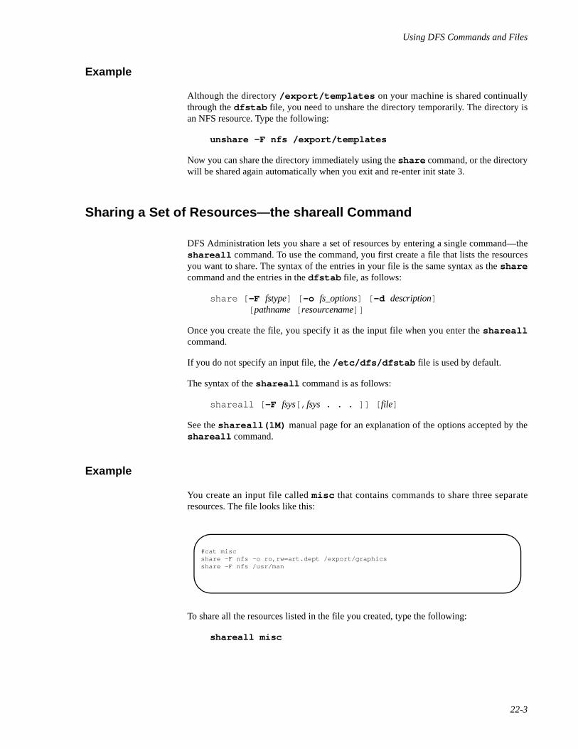
Using DFS Commands and Files
22-3
Example 22
Although the directory /export/templates on your machine is shared continuallythrough the dfstab file, you need to unshare the directory temporarily. The directory isan NFS resource. Type the following:
unshare -F nfs /export/templates
Now you can share the directory immediately using the share command, or the directorywill be shared again automatically when you exit and re-enter init state 3.
Sharing a Set of Resources—the shareall Command 22
DFS Administration lets you share a set of resources by entering a single command—theshareall command. To use the command, you first create a file that lists the resourcesyou want to share. The syntax of the entries in your file is the same syntax as the sharecommand and the entries in the dfstab file, as follows:
share [ -F fstype] [ -o fs_options] [ -d description] [ pathname [ resourcename]]
Once you create the file, you specify it as the input file when you enter the shareallcommand.
If you do not specify an input file, the /etc/dfs/dfstab file is used by default.
The syntax of the shareall command is as follows:
shareall [ -F fsys[, fsys . . . ]] [ file]
See the shareall(1M) manual page for an explanation of the options accepted by theshareall command.
Example 22
You create an input file called misc that contains commands to share three separateresources. The file looks like this:
To share all the resources listed in the file you created, type the following:
shareall misc
#cat miscshare -F nfs -o ro,rw=art.dept /export/graphicsshare -F nfs /usr/man

Network Administration
22-4
To share only the NFS resources listed in the misc file, type the following:
shareall -F nfs misc
Unsharing a Set of Resources—the unshareall Command 22
DFS Administration provides you with the unshareall command, which lets youunshare all the shared resources on your system, or all the shared resources of a specifiedfile system type. The syntax of the unshareall command is
unshareall [ -F fsys[, fsys . . . ]]
When you specify a file system type, the command unshares all local resources of thedistributed file system type you specified. If no -F option is specified, then the commandunshares all local resources currently shared.
For unshareall , see the shareall(1M) manual page for an explanation of theoptions accepted by the unshareall command.
Example 22
You want to unshare all currently shared local resources, regardless of file system type.Type the following:
unshareall
Mounting and Unmounting Remote Resources 22
This section tells you how to mount and unmount remote resources explicitly, using thegeneric mount, umount, mountall, and umountall commands. It also tells youhow to mount remote resources automatically, using the /etc/vfstab file. Thecommand and files described in this section are described only as they relate to theadministration of remote resources.
If you have the Enhanced Security Utilities installed, it is important that you understandthat privileges are assigned to executables locally. When you mount an executable from aserver, it is mounted without privileges, regardless of the privileges assigned to theexecutable on the server. For example, nfstart may have appropriate privilegesassigned to it on the server, however; when you mount the server's /usr, nfstart doesnot have privilege automatically on your system. If the executable requires privilege, youmust assign privileges to the executable using the filepriv command, just as youwould if the executable were local to your system. Once you assign privileges on theclient, you can mount the resource or add it to the vfstab file. If, later, you unmount theresource or remove the relevant entry from vfstab, you should also remove theexecutable's privileges on the client, using the filepriv command with the -d option. Ifyou fail to remove privileges on the client, the system displays an error message everytime you re-boot.
Using DFS Commands and Files
22-5
Mounting a Remote Resource Explicitly—the mount Command 22
The mount command allows you to mount both local and remote file systems. To mount aremote resource using the mount command, you must be able to reach, via a network, theserver that is sharing the resource you want to mount.
The syntax of the mount command as it relates to mounting distributed file systems is:
mount [ -F FSType] [ -V ] [ current_options] [ -o specific_options]{ special | mount_point}
mount [ -F FSType] [ -V ] [ current_options] [ -o specific_options]special mount_point
See the mount(1M) manual page for an explanation of the options accepted by themount command.
For information about NFS-specific options, see Chapter 26, "Sharing and Mounting NFSResources Explicitly".
Resources mounted explicitly with the mount command stay mounted unless youunmount them, using umount , or if you exit init state 3. If you exit init state 3 and re-enterit, the resource is no longer mounted (unless you edited the /etc/vfstab file to includethe mount automatically).
Example 1 22
You want to mount an NFS resource residing on a server called “tools.srv.” The resource isa directory called graphics in the server's /usr directory. You created a mount pointcalled graphics in your /usr/tools directory. You want to mount the resource read/write, and you want set-uid bits to be ignored. Type the following:
mount -F nfs -o nosuid tools.srv:/usr/graphics\ /usr/tools/graphics
Because no access rights are specified, the directory is mounted read/write.
Example 2 22
You want to hard mount a directory containing manual pages that resides on a servercalled “docgroup.” You want the directory mounted read-only, with interrupt enabled. Thedirectory is an NFS resource named /usr/man . You want to mount the directory to amount point of the same name on your machine. Type the following:
mount -F nfs -o ro,intr docgroup:/usr/man /usr/man
Example 3 22
Assume you have the Enhanced Security Utilities installed and you want to mount an NFSresource residing on a server called “tools.srv.” The resource is a directory calledgraphics in the server's /usr directory. You created a mount point called graphics
Network Administration
22-6
in your /usr/tools directory. You want the level ceiling of the resource to be a levelthat has the alias Tools. Type the following:
mount -l Tools -F nfs tools.srv:/usr/graphics \ /usr/tools/graphics
Mounting a Remote Resource Automatically—the /etc/vfstab File 22
The /etc/vfstab file allows you to mount a local file system automatically when youboot the system. If you edit the file to include a remote file system or directory, the remoteresource is mounted automatically when you take the system to init state 3.
To mount a remote resource automatically, create a mount point for the resource using themkdir command, then edit the vfstab file. Entries in the vfstab file require thefollowing syntax:
special fsckdev mountp fstype fsckpass automnt mntopts fsceiling
See the vfstab(4) manual page for a description of the fields in the /etc/vfstabfile.
Once you create the mount point and edit the /etc/vfstab file, the file system ordirectory will be mounted automatically when you enter init state 3. It will be mountedautomatically every time you enter init state 3 until you modify the vfstab file (unless,of course, the server sharing the directory unshares it). The contents of /etc/vfstabremain the same until you edit the file.
Example 22
Assume you want to mount the resource /usr/share from a server named “frontoffice.”You want the resource to be mounted automatically every time you take your system toinit state 3. The directory is an NFS resource. You want to mount the directory on themount point /usr/local/tmp with read-only access. First create the mount point bytyping the following:
mkdir /usr/local/tmp
Make sure the mode and permissions of the new mount point match those of the resourceyou want to mount on it. Then edit the /etc/vfstab file, using any supported texteditor. The file entry should look like this:
frontoffice:/usr/share - /usr/local/tmp nfs - yes ro
Unmounting a Remote Resource—the umount Command 22
The umount command allows you to unmount both local and remote file systems. Youcan unmount a resource with umount whether is was mounted explicitly using the mountcommand or automatically through the vfstab file.
Using DFS Commands and Files
22-7
The syntax of the umount command, as it relates to unmounting distributed file systems,is:
umount [ -V ] [ -o specific_options] { resource | mount_point}
For umount , see the mount(1M) manual page for an explanation of the optionsaccepted by the umount command.
Example 22
You want to unmount a remote NFS resource by specifying the server sharing the resourceand the pathname of the resource on the server. Type the following command:
umount docgroup:/usr/man
Mounting a Set of Resources—the mountall Command 22
DFS Administration lets you mount a set of resources by entering a single command—themountall command. To use the command, you first create a file that lists the resourcesyou want to mount. The syntax of the entries in your file is the same syntax as the entriesin the /etc/vfstab file, as follows:
special fsckdev mountp fstype fsckpass automnt mntopts fsceiling
See the vfstab(4) manual page for a description of the fields in the /etc/vfstabfile.
Once you create a file, you specify it as the input file for the mountall command.
If you do not specify an input file, the /etc/vfstab file is used by default.
The syntax of the mountall command is as follows:
mountall [ -F FSType] [ -l | -r ] [ file_system_table]
See the mountall(1M) manual page for an explanation of the options accepted by themountall command.
If the mountall command is entered without arguments, it mounts all local file systemsand remote resources in the vfstab file that have the automnt field set to “yes.”
Example 22
Your system mounts resources automatically when you entered init state 3, using the/etc/vfstab file. While resources are still mounted, you add entries to the vfstabfile. Now you want to mount the resources you added to the file, without exiting init state 3and unmounting currently mounted resources. Type the following command:
mountall -r
Network Administration
22-8
The system uses the updated vfstab file as the input file. It mounts all remote resourcesin the file that are not currently mounted and displays error messages for those resourcesthat are mounted already.
Unmounting a Set of Resources—the umountall Command 22
DFS Administration utilizes the umountall command, which lets you unmountmounted resources on your system or all the mounted resources of a specified file systemtype. The syntax of the umountall command is the following:
umountall [ -F FSType] [ -k ] [ -l | -r ]
For umountall , see the mountall(1M) manual page for an explanation of theoptions accepted by the umountall command.
Example 22
You want to unmount all remote file systems currently mounted on your system. You wantto kill all processes that have open files. Type the following:
umountall -k -r
Displaying Information 22
This section tells you how to determine what resources are available to you from networkservers, what resources are shared and mounted on your system, and what resourcesshared on your system have been mounted by network clients. The commands describedin this chapter are the share , mount , dfshares , and dfmounts commands.
Displaying Shared Local Resources—the share Command 22
You use the share command to share resources on your system with network clients;however, you can also use the command to display information about shared resources onyour system. The command's syntax when used in this capacity is:
share [ -F fstype]
If you enter the command without arguments, it displays all NFS resources on your systemthat are currently shared. If you specify a file system type and no other options, thecommand displays all resources of the specified type that are currently shared.
Using DFS Commands and Files
22-9
Displaying Mounted Resources—the mount Command 22
Generally, you use the mount command to mount local and remote resources on yoursystem. However, if you enter the command without arguments, it displays a list of localand remote resources that are currently mounted on your system.
NOTE
You cannot limit the display to remote resources or to resources ofa specific file system type by entering arguments. If you entermount -F nfs, for example, the system displays an error mes-sage.
Browsing Shared Remote Resources—the dfshares Command 22
To “browse” shared resources means to determine what resources are available fromremote systems. For browsing, DFS Administration gives you the dfshares command,which displays information about the NFS resources that are available from networkservers. The syntax of the dfshares command is:
dfshares [ -F fstype] [ -h ] [ -o fs_options] [ server . . .]
See dfshares(1M) for an explanation of the options accepted by the dfsharescommand.
The syntax of the server option depends on the server's file system type. You can use asystem name, which specifies a system in the domain of the local system, a domain name,which specifies all the systems in the domain, or you can enter both the domain and thesystem, in the form domain.system, to display resources on a specific remote system in aremote domain.
To display resources on an NFS server, you can enter a system name for the server option,which specifies a system on the network.
When you enter the command, your system displays output consisting of the fields:
resource server access transport description
where resource is the shared resource name; server is the system from which the resourceis available; access refers to the access granted to client systems—either read/write orread-only; transport is the transport provider over which communication is carried, such astcp; and description is a description of the resource provided by an administrator when theresource was shared.
For NFS resources, the command cannot determine the access rights granted to clientsystems or the transport provider; therefore, the access and transport fields are filled withhyphens (-) when dfshares displays a list of NFS resources. The description field doesnot appear at all in a display of NFS resources.
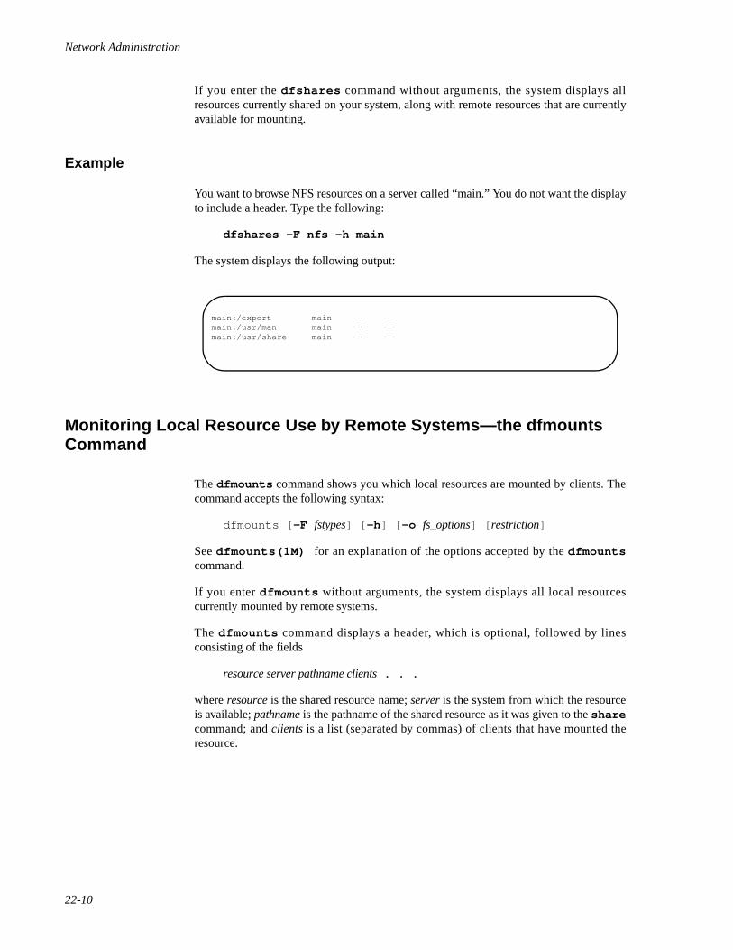
Network Administration
22-10
If you enter the dfshares command without arguments, the system displays allresources currently shared on your system, along with remote resources that are currentlyavailable for mounting.
Example 22
You want to browse NFS resources on a server called “main.” You do not want the displayto include a header. Type the following:
dfshares -F nfs -h main
The system displays the following output:
Monitoring Local Resource Use by Remote Systems—the dfmounts Command 22
The dfmounts command shows you which local resources are mounted by clients. Thecommand accepts the following syntax:
dfmounts [ -F fstypes] [ -h ] [ -o fs_options] [ restriction]
See dfmounts(1M) for an explanation of the options accepted by the dfmountscommand.
If you enter dfmounts without arguments, the system displays all local resourcescurrently mounted by remote systems.
The dfmounts command displays a header, which is optional, followed by linesconsisting of the fields
resource server pathname clients . . .
where resource is the shared resource name; server is the system from which the resourceis available; pathname is the pathname of the shared resource as it was given to the sharecommand; and clients is a list (separated by commas) of clients that have mounted theresource.
main:/export main - -main:/usr/man main - -main:/usr/share main - -

Using DFS Commands and Files
22-11
Example 22
You want to see which clients are mounting the NFS resources on the system called“main.” You do not want a header to be displayed. Type the following:
dfmounts -F nfs -h main
The system displays the following output:
- main /export dancer, runner- main /usr/man jogger- main /usr/share dancer, runner

Network Administration
22-12
23DFS sysadm Interface
Introduction to the DFS sysadm Interface . . . . . . . . . . . . . . . . . . . . . . . . . . . . . . . . . 23-1The DFS Management Menu Tree . . . . . . . . . . . . . . . . . . . . . . . . . . . . . . . . . . . . . . 23-1DFS Menu Options . . . . . . . . . . . . . . . . . . . . . . . . . . . . . . . . . . . . . . . . . . . . . . . . . . 23-2

Network Administration
23-1
23Chapter 23DFS sysadm Interface
232323
Introduction to the DFS sysadm Interface 23
The OS provides a menu interface to system administration called System AdministrationMenus (or sis-adam, because it is accessed through the sysadm command). When youinstall DFS Administration Utilities, menus are added to the interface for administeringdistributed file systems. These menus are known collectively as the Distributed FileSystem Management menus. This section describes the DFS Management menus and theoptions the menus provide.
A complete description of the menu interface, including a tutorial, appears in the chapter“Using the sysadm Interface” in the System Administration guide.
The DFS Management Menu Tree 23
All DFS Administration commands can be accessed through the Distributed File SystemManagement menus in the System Administration Menus.
To display the DFS Management menus, do the following:
1. Type sysadm network_services .
The Network Services Management menu is displayed.
2. From the Network Services Management menu, select the optionremote_files .
The Distributed File System Management menu is displayed.
From the Distributed File System Management menu, you can access submenus thatprovide you with commands that correspond to the commands described in this guide.
Here is an illustration of sysadm menus that relate to distributed file system administra-tion:
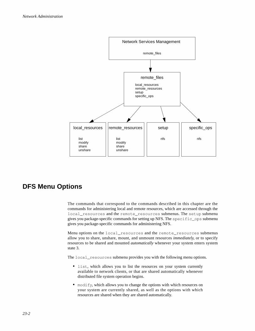
Network Administration
23-2
DFS Menu Options 23
The commands that correspond to the commands described in this chapter are thecommands for administering local and remote resources, which are accessed through thelocal_resources and the remote_resources submenus. The setup submenugives you package-specific commands for setting up NFS. The specific_ops submenugives you package-specific commands for administering NFS.
Menu options on the local_resources and the remote_resources submenusallow you to share, unshare, mount, and unmount resources immediately, or to specifyresources to be shared and mounted automatically whenever your system enters systemstate 3.
The local_resources submenu provides you with the following menu options.
• list , which allows you to list the resources on your system currentlyavailable to network clients, or that are shared automatically wheneverdistributed file system operation begins.
• modify , which allows you to change the options with which resources onyour system are currently shared, as well as the options with whichresources are shared when they are shared automatically.
Network Services Management
remote_files
setupremote_resourceslocal_resources specific_ops
remote_files
setupremote_resourceslocal_resources
specific_ops
sharemodifylist
unsharesharemodifylist
unshare
nfs nfs
DFS sysadm Interface
23-3
• share , which allows you to share selected resources on your system withnetwork clients. The menu option lets you share resources immediately orspecify resources to be shared automatically.
• unshare , which allows you to unshare resources on your system that arecurrently shared with network clients. The menu option also lets you cancelthe automatic sharing of local resources.
The remote_resources submenu provides you with the following menu options:
• list , which allows you to list the remote resources that are currentlymounted on your system and the remote resources that are mountedautomatically.
• modify , which allows you to change the options with which remoteresources are currently mounted on your system, as well as the options withwhich remote resources are mounted when they are mounted automatically.
• mount , which allows you to mount remote resources on your system andmake them available to your users. The menu option lets you mountresources immediately, and specify resources to be mounted automaticallyevery time distributed file system operation begins.
• unmount , which allows you to unmount currently mounted remoteresources. The menu option also lets you cancel the automatic mounting ofremote resources.
Once you select a menu option from either submenu, screen messages and prompts leadyou through the task you want to perform. If a message or a prompt is unclear to you, youcan display a help screen, which gives you additional information for completing the task.

Network Administration
23-4

-5
5Part 5Network File System Administration
Replace with Part 5 tab

Network Administration
-6
24Introduction to NFS Administration
About NFS Administration . . . . . . . . . . . . . . . . . . . . . . . . . . . . . . . . . . . . . . . . . . . . 24-1How This Part is Organized . . . . . . . . . . . . . . . . . . . . . . . . . . . . . . . . . . . . . . . . 24-1
Introduction to NFS . . . . . . . . . . . . . . . . . . . . . . . . . . . . . . . . . . . . . . . . . . . . . . . . . . 24-2NFS Version 3. . . . . . . . . . . . . . . . . . . . . . . . . . . . . . . . . . . . . . . . . . . . . . . . . . . 24-2NFS Resources . . . . . . . . . . . . . . . . . . . . . . . . . . . . . . . . . . . . . . . . . . . . . . . . . . 24-3NFS Servers and Clients. . . . . . . . . . . . . . . . . . . . . . . . . . . . . . . . . . . . . . . . . . . 24-4
An Overview of NFS Administration . . . . . . . . . . . . . . . . . . . . . . . . . . . . . . . . . . . . 24-5

Network Administration
24-1
24Chapter 24Introduction to NFS Administration
242424
About NFS Administration 24
The OS allows you to share files, file hierarchies, and entire file systems across a networkusing the Network File System (NFS).
The NFS administration chapters explain how to administer the implementation of theNetwork File System. They explain how NFS works, and provide the procedures forsharing resources on the network, and for accessing resources shared by other machines.
How This Part is Organized 24
The NFS administration chapters assume you are setting up your machine both to sharelocal resources on the network, and to mount remote resources shared by other systems. Ifyou are administering a machine that will mount but not share resources, you can limityour reading to the NFS overview in this chapter, and to the chapters that explain how tomount resources, set up network security, and diagnose problems on an NFS client.
The NFS chapters are organized as follows:
• “Introduction to NFS Administration,” which describes this guide andprovides an introduction to NFS.
• “Setting Up NFS,” which directs you to installation instructions and tellsyou how to start NFS operation and set up automatic sharing and mounting.If you have the Enhanced Security Utilities installed, you are directed toinstructions for setting up security on a server running Mandatory AccessControl (MAC) and the Least Privilege Mechanism (LPM).
• “Sharing and Mounting NFS Resources Explicitly,” which tells you how toshare and mount resources on an “as needed” basis, using the commandline.
• “Obtaining NFS Information,” which tells you how to get informationabout resources that have been shared and mounted across the network.
• “Troubleshooting and Tuning NFS,” which provides solutions to problemsyou may encounter when using NFS.
• “Setting Up Secure NFS,” which introduces options to NFS that providefor encryption and other security measures.
• “Using the NFS Automounter,” which tells you how to use the automaticmounting facility of NFS.
Network Administration
24-2
• “The NFS Network Lock Manager,” which discusses how to preventmultiple processes from modifying the same file at the same time.
• “Using the NFS sysadm Interface,” which tells you how to set up andadminister NFS through a series of sysadm(1M) menus.
Introduction to NFS 24
NFS is a service that enables machines of different architectures running differentoperating systems to share resources across a network. NFS makes it possible for amachine to share local files and directories, and permits remote users to access those filesand directories as though they were local to the user's machine.
NFS provides file sharing in a heterogeneous environment, potentially containing manydifferent operating systems; it has been implemented on operating systems including MS-DOS and VMS.
NFS can be implemented on different operating systems because it defines an abstractmodel of a file system. On each operating system, the NFS model is mapped into the localfile system semantics. As a result, normal file system operations, such as read/write,operate in the same way that they operate on a local file system.
The benefits of NFS are significant. NFS allows multiple machines to use the same files,so the same data can be accessible to everyone on the network. Storage costs can be keptdown by having machines share applications.
NFS Version 3 24
NFS Version 3 was an enhancement provided by PowerMAX OS Version 5.1. NFSVersion 3 offers substantial enhancements over NFS Version 2. These enhancementsinclude, but are not limited to, the following:
Improved client write throughput.
Reduced server load resulting in increased scalability and performance.
Support for large (multi-gigabyte) files on NFS servers.
To address backward compatibility with the installed base using NFS Version 2, Concur-rent has implemented NFS in this release so that both protocols are supported concur-rently.
Changes for NFS Version 3 are shown below. See the table below additional information.
• The NFS3 maximum file size is 17,179,869,184GB - 1 =18,446,744,073,709,551,615 bytes.
• The NFS2 maximum file size is 2GB - 1 = 2,147,483,647 bytes.
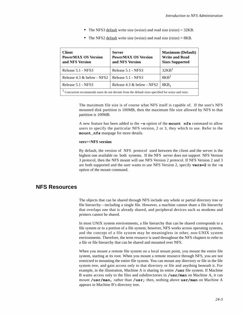
Introduction to NFS Administration
24-3
• The NFS3 default write size (wsize) and read size (rsize) = 32KB.
• The NFS2 default write size (wsize) and read size (rsize) = 8KB.
The maximum file size is of course what NFS itself is capable of. If the user's NFSmounted disk partition is 100MB, then the maximum file size allowed by NFS to thatpartition is 100MB.
A new feature has been added to the -o option of the mount nfs command to allowusers to specify the particular NFS version, 2 or 3, they which to use. Refer to themount_nfs manpage for more details.
vers=<NFS version
By default, the version of NFS protocol used between the client and the server is thehighest one available on both systems. If the NFS server does not support NFS Version3 protocol, then the NFS mount will use NFS Version 2 protocol. If NFS Version 2 and 3are both supported and the user wants to use NFS Version 2, specify vers=2 in the -ooption of the mount command.
NFS Resources 24
The objects that can be shared through NFS include any whole or partial directory tree orfile hierarchy—including a single file. However, a machine cannot share a file hierarchythat overlaps one that is already shared, and peripheral devices such as modems andprinters cannot be shared.
In most UNIX system environments, a file hierarchy that can be shared corresponds to afile system or to a portion of a file system; however, NFS works across operating systems,and the concept of a file system may be meaningless in other, non-UNIX systemenvironments. Therefore, the term resource is used throughout the NFS chapters to refer toa file or file hierarchy that can be shared and mounted over NFS.
When you mount a remote file system on a local mount point, you mount the entire filesystem, starting at its root. When you mount a remote resource through NFS, you are notrestricted to mounting the entire file system. You can mount any directory or file in the filesystem tree, and gain access only to that directory or file and anything beneath it. Forexample, in the illustration, Machine A is sharing its entire /usr file system. If MachineB wants access only to the files and subdirectories in /usr/man on Machine A, it canmount /usr/man, rather than /usr; then, nothing above usr/man on Machine Aappears in Machine B’s directory tree.
ClientPowerMAX OS Versionand NFS Version
ServerPowerMAX OS Versionand NFS Version
Maximum (Default)Write and Read Sizes Supported
Release 5.1 - NFS3 Release 5.1 - NFS3 32KB1
Release 4.3 & below - NFS2Release 5.1 - NFS3 8KB1
Release 5.1 - NFS3 Release 4.3 & below - NFS28KB1
1 Concurrent recommends users do not deviate from the default sizes specified for wsize and rsize.
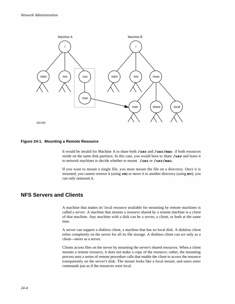
Network Administration
24-4
Figure 24-1. Mounting a Remote Resource
It would be invalid for Machine A to share both /usr and /usr/man if both resourcesreside on the same disk partition. In this case, you would have to share /usr and leave itto network machines to decide whether to mount /usr or /usr/man.
If you want to mount a single file, you must mount the file on a directory. Once it ismounted, you cannot remove it (using rm) or move it to another directory (using mv); youcan only unmount it.
NFS Servers and Clients 24
A machine that makes its' local resource available for mounting by remote machines iscalled a server. A machine that mounts a resource shared by a remote machine is a clientof that machine. Any machine with a disk can be a server, a client, or both at the sametime.
A server can support a diskless client, a machine that has no local disk. A diskless clientrelies completely on the server for all its file storage. A diskless client can act only as aclient—never as a server.
Clients access files on the server by mounting the server's shared resources. When a clientmounts a remote resource, it does not make a copy of the resource; rather, the mountingprocess uses a series of remote procedure calls that enable the client to access the resourcetransparently on the server's disk. The mount looks like a local mount, and users entercommands just as if the resources were local.
/
161160
/sbin /etc /usr
man
Machine A Machine B
/
/sbin /etc /man
man share local
Introduction to NFS Administration
24-5
An Overview of NFS Administration 24
Your responsibilities as an NFS administrator depend on your site's requirements and therole of your machine on the network. You may be responsible for all the machines on yourlocal network, in which case you may be responsible for installing the software on everymachine, determining which machines, if any, should be dedicated servers, which shouldact as both servers and clients, and which should be clients only.
If your site has a network administrator, and you are the administrator of a client-onlymachine, you may be responsible only for mounting and unmounting remote resources onthat machine.
Maintaining a machine once it has been set up involves the following tasks:
• Starting and stopping NFS operation.
• Sharing and unsharing resources.
• Mounting and unmounting resources.
• Modifying administrative files to update the lists of resources your machineshares and/or mounts automatically.
• Checking the status of the network.
• Diagnosing and fixing NFS-related problems as they arise.
• Maintaining security.
• Setting up maps to use the optional automatic mounting facility called theAutomounter.

Network Administration
24-6

25Setting Up NFS
Introduction to NFS Setup. . . . . . . . . . . . . . . . . . . . . . . . . . . . . . . . . . . . . . . . . . . . . 25-1Starting and Stopping NFS Operation . . . . . . . . . . . . . . . . . . . . . . . . . . . . . . . . . . . . 25-2Setting Up Automatic Sharing. . . . . . . . . . . . . . . . . . . . . . . . . . . . . . . . . . . . . . . . . . 25-2Setting Up Automatic Mounting . . . . . . . . . . . . . . . . . . . . . . . . . . . . . . . . . . . . . . . . 25-4
Automatic Mounting Example . . . . . . . . . . . . . . . . . . . . . . . . . . . . . . . . . . . . . . 25-5NFS as a Dynamically Loadable Module . . . . . . . . . . . . . . . . . . . . . . . . . . . . . . . . . 25-5

Network Administration
25-1
25Chapter 25Setting Up NFS
252525
Introduction to NFS Setup 25
Setting up NFS involves the following tasks:
• Installing NFS software on your servers and clients (for information oninstalling the NFS software, see the Release Notes).
• Setting up automatic sharing on servers
• Setting up automatic mounting on clients
• Starting NFS operation
The NFS software can be configured in multiple ways to suit the needs of your machine. Itcan be configured as:
• a client only NFS system
• a server only NFS system
• both a client and server NFS system
There are four NFS modules:
• nfss - code and structures common to both client and server NFS, static portion
• nfscmn - code and structures common to both client and server NFS, can be a DLM module
• nfs - code and structures for client NFS, can be a DLM module
• nfssrv - code and structures for server NFS, can be a DLM module
The nfss and nfscmn modules must always be enabled to use NFS. At least one of the nfsor nfssrv modules must be enabled. When the NFS software is installed on a machine, it isconfigured by default as both a client and a server NFS machine (all four modulesenabled).
The kernel lock manager module klm must be enabled for client NFS configurations, but itis not used by the server NFS module. Networking must be enabled for all NFSconfigurations.
Remember, a machine can be both a server and a client—both sharing local resources withremote machines and mounting remote resources. Throughout the NFS chapters, it isassumed you are setting up your machine as both a server and a client. If you are setting up
Network Administration
25-2
machines that are to be dedicated servers or clients, follow the instructions for sharing andmounting as appropriate.
Starting and Stopping NFS Operation 25
If NFS is installed on your system, your system will come up in init state 3, and NFS willbe started automatically.
If your system is not in init state 3, you can take your system to init state 3 by enteringinit 3, or you can set up your system to enter init state 3 immediately on rebooting (forinformation, see the chapter “Booting and System States” in the System Administrationguide.)
NFS allows you to share and mount resources explicitly, by entering commands at thecommand line. You can also set up the system to share and mount resources automatically,by editing a few of administration files. If you set up automatic sharing and mounting, apre-determined set of resources is shared and/or mounted whenever you start NFSoperation.
To start NFS using the command line, type the following command:
sh /etc/init.d/nfs start
To stop NFS using the command line, type the following command:
sh /etc/init.d/nfs stop
When NFS is stopped, the resources you shared and mounted are automatically unsharedand unmounted.
If your system does not automatically enter init state 3 upon start-up or reboot, edit the/etc/inittab file and change the line
is:2:initdefault:
to the following:
is:3:initdefault:
See inittab(4) for more information on the /etc/inittab file.
Setting Up Automatic Sharing 25
If you want to set up your system so that certain files and directories are sharedautomatically whenever you start NFS operation, you need to edit an administrative file. Itis recommended that you set up automatic sharing when you first set up NFS if you needto share the same set of resources on a regular basis. For example, if your machine is aserver that supports diskless clients, you need to make your clients' root directoriesavailable at all times.
Setting Up NFS
25-3
The file you need to edit to set up automatic sharing is dfstab , located in /etc/dfs .dfstab is installed by the Distributed File System Administration Utilities.
The dfstab file lists all the resources that your server shares with its clients and controlswhich clients may mount a resource. If you want to modify dfstab to add or delete aresource, or to modify the way sharing is done, simply edit the file with your text editor.The next time the machine enters init state 3, the system reads the updated dfstab todetermine which resources should be shared automatically.
Each line in the file consists of a share command—the same command you enter at thecommand line to share a resource explicitly. The share command is located in /usr/sbin . When it is used to share a resource over NFS, it has the following syntax:
share [ -F nfs] [ -o specific-options] [ -d description] pathname
See the NFS-specific share(1M) manual page for the options supported by theshare command.
You can omit the -F option if
nfs Network File System Utilities: Version x.x
is the first line in /etc/dfs/fstypes or if it is the only Distributed File System (DFS)package installed. If NFS is the only DFS package installed, it becomes the default for the-F option.
If you enter the -d option, the description is stored in your sharetab file. However,clients will not see the description displayed when they use the dfshares command tolist the resources shared on your system.
Under NFS, a server shares resources it owns so clients can mount them. However, a userwho becomes the superuser on a client may be denied superuser access to mounted remoteresources, unless the appropriate option is used when the resource is shared. Otherwise,when a user logged in as root on one host requests access to a remote file shared throughNFS, the user's ID is changed from 0 to the user ID of the username nobody. The accessrights of user nobody are the same as those given to the public for a particular file. Forexample, if the public only has execute permission for a file, then user nobody can onlyexecute that file.
When you share a resource, you can permit root on a particular machine to have rootaccess to that resource (provided you do not have the Enhanced Security Utilitiesinstalled) by editing /etc/dfs/dfstab on the server, or by specifying the appropriateoptions on the command line. For example, suppose you want the machine “samba” (butno others) to have superuser access to the shared directory /usr/src. You enter thefollowing command in /etc/dfs/dfstab, or on the command line.
share -F nfs -o root=samba /usr/src
If you want more than one client to have root access, you can specify a list, as follows:
share -F nfs -o root=samba:raks:jazz /usr/src
If you want all client processes with uid 0 to have superuser access to /usr/src, youenter
share -F nfs -o anon=0 /usr/src
Network Administration
25-4
anon is short for “anonymous.” Anonymous requests, by default, get their user IDchanged from its previous value (whatever it may be) to the user ID of usernamenobody. NFS servers label as anonymous any request from a root user (someone whosecurrent effective user ID is 0) who is not in the list following the root= option in theshare command. The command above tells the kernel to use the value 0 for anonymousrequests. The result is that all root users retain their user ID of 0.
Setting Up Automatic Mounting 25
Once a resource has been shared on a server through NFS, it can be accessed from a client.Mounting can be done automatically when NFS operation begins on the client (when theclient enters init state 3), or explicitly, by executing the NFS start-up script (/etc/init.d/nfs ) on the command line. If you need to mount certain remote resources on aregular basis, it is recommended that you set up automatic mounting when you first set upNFS operation. Automatic mounting is handled through the /etc/vfstab file.
NOTE
A server can be a client of another server on a local network, inwhich case, the server's vfstab may need to include both localand remote mounts. For information about adding local mounts tothe vfstab file, see the chapter “Managing File System Types”in the System Administration guide.
If you have the Enhanced Security Utilities installed and you're supporting the LeastPrivilege Mechanism (LPM), be aware that privileges are assigned to executables locally.When you mount an executable from a server, it is mounted without privileges, regardlessof the privileges assigned to the executable on the server. If the executable requiresprivilege, assign privileges to the executable using the filepriv command. If youunmount the resource, you should also remove the executable's privileges on the client,using the filepriv command with the -d option. If you fail to remove privileges on theclient, the system displays an error message every time you re-boot. For more information,see the filepriv(1M) manual page.
Entries in the /etc/vfstab file have the following syntax:
special fsckdev mountp fstype fsckpass automnt mntopts fsceiling
See the vfstab(4) manual page for an explanation of the fields in the /etc/vfstabfile.
The contents of /etc/vfstab remain the same until you change them.
Setting Up NFS
25-5
Automatic Mounting Example 25
To specify that the directory /usr/local of the server dancer should be mountedautomatically on the client's directory /usr/local/tmp with read/only permission, youadd the following line to the client's vfstab.
dancer:/usr/local - /usr/local/tmp nfs - yes ro
If you have the Enhanced Security Utilities package installed, you might enter
dancer:/usr/local - /usr/local/tmp nfs - yes ro USER_PUBLIC
where USER_PUBLIC is the level ceiling.
NFS as a Dynamically Loadable Module 25
NFS can be configured into the system as Dynamically Loadable Modules (DLMs).DLMs are kernel modules (such as device drivers, file systems, and streams modules) thatcan be loaded into and unloaded from the system during runtime.
By using DLMs, system administrators can avoid the work that was previously necessary(doing an idbuild, shutting down the system, bringing it back up, and so on) every timethey install or remove a new kernel module.
DLMs also conserve system resources by providing a mechanism for loading kernelmodules only when they are needed in the system. When a loaded kernel module is nolonger in-use, the DLM feature can unload the module to reclaim the resources itoccupied.
Loading and unloading of the NFS DLMs is slightly different than other DLMs. BecauseNFS daemons will be accessing the NFS DLM modules on a continual basis, the NFSDLM kernel modules will not be dynamically unloaded by the kernel DLM mechanismeven though NFS activity becomes infrequent. The NFS DLM modules will be unloadedon demand when the system goes from init state 3 to init state 2. Dynamic and demandunloading of NFS will only take place when all NFS daemons have been killed and allremotely mounted file systems have been unmounted.
Dynamic loading and unloading can be performed on demand by the systemadministrator, or automatically by the kernel. For more information about the DLMfeature, refer to the chapter “Managing Dynamically Loadable Modules” in the SystemAdministration guide.

Network Administration
25-6
26Sharing and Mounting NFS Resources Explicitly
Sharing and Unsharing NFS Resources. . . . . . . . . . . . . . . . . . . . . . . . . . . . . . . . . . . 26-1Sharing NFS Resources with the share Command. . . . . . . . . . . . . . . . . . . . . . . 26-1
NFS share Examples . . . . . . . . . . . . . . . . . . . . . . . . . . . . . . . . . . . . . . . . . . 26-1Sharing a Set of NFS Resources with the shareall Command . . . . . . . . . . . . . . 26-2
NFS shareall Example. . . . . . . . . . . . . . . . . . . . . . . . . . . . . . . . . . . . . . . . . 26-2Unsharing NFS Resources with the unshare Command. . . . . . . . . . . . . . . . . . . 26-3
NFS unshare Example. . . . . . . . . . . . . . . . . . . . . . . . . . . . . . . . . . . . . . . . . 26-3Unsharing NFS Resources with the unshareall Command. . . . . . . . . . . . . . . . . 26-3
Mounting and Unmounting NFS Resources . . . . . . . . . . . . . . . . . . . . . . . . . . . . . . . 26-3Mounting NFS Resources with the mount Command . . . . . . . . . . . . . . . . . . . . 26-4
NFS mount Examples . . . . . . . . . . . . . . . . . . . . . . . . . . . . . . . . . . . . . . . . . 26-4Unmounting NFS Resources with the umount Command . . . . . . . . . . . . . . . . . 26-5

Network Administration
26-1
26Chapter 26Sharing and Mounting NFS Resources Explicitly
262626
Sharing and Unsharing NFS Resources 26
In addition to sharing and unsharing resources automatically, you can share and unshareexplicitly by entering commands on the command line. To share resources explicitly, usethe share and shareall commands; to unshare explicitly, use the unshare andunshareall commands.
Sharing NFS Resources with the share Command 26
The share command lets you share resources as needed. You should use share at thecommand line prompt when you want to share a resource for a brief period of time, or onan irregular basis.
The share command is located in /usr/sbin and has the following syntax:
share [ -F nfs] [ -o specific-options] [ -d description] pathname
See NFS-specific share(1M) for the options supported by the share command.
If you enter the -d option, the description is stored in your sharetab file. However,clients will not see the description displayed when they use the dfshares command tolist the resources shared on your system.
NFS share Examples 26
1. To share the directory /usr with all the server's clients, enter the followingcommand:
share -F nfs /usr
The resource is shared with read/write permissions by default.
2. If you want to make sure that client dancer can access /usr with read-only permission, enter the following command:
share -F nfs -o rw,ro=dancer /usr
3. If you want to see a listing of the local resources currently availablethrough NFS, enter the following command:
share -F nfs
Network Administration
26-2
If you have more than one distributed file system package installed, theshare command without arguments displays a list of all the resourcesshared on your system through the default file sharing package, with thedefault being the first file system type listed in /etc/dfs/fstypes .
4. Assume you are running the Enhanced Security Utilities. If you want usersor processes on clients jogger and jumper with an effective UID of 0 toaccess /usr with superuser permission, enter the following command:
share -F nfs -o root=jogger:jumper /usr
5. If you want to permit root access on /usr by any user or process whoseuser ID is 0, enter the following command:
share -F nfs -o anon=0 /usr
You would share a resource this way only if you are in a trustingenvironment.
Sharing a Set of NFS Resources with the shareall Command 26
The shareall command allows you to share a set of resources. To use the command,you first create a file that lists the resources you want to share. The syntax of the entries inyour file is the same syntax as the NFS-specific share command and the entries in thedfstab file, as follows:
share [ -F nfs] [ -o specific_options] [ -d description] [ pathname]
Once you create the file, you specify it as the input file when you enter the shareallcommand.
If you do not specify an input file, the /etc/dfs/dfstab file is used by default.
The syntax of the shareall command is as follows:
shareall [ -F nfs] [ file]
See shareall(1M) for the options supported by the shareall command.
NFS shareall Example 26
You need to share the same set of resources on a fairly regular basis, but you do not wantthe resources shared automatically. You create an input file called misc that looks likethis:
#cat miscshare -F nfs -o ro,rw=artdept /export/graphicsshare -F nfs /usr/manshare -F nfs -o rw,ro=dancer,root=jogger:jumper /local
To share the resources listed in the misc file, type
shareall misc
Sharing and Mounting NFS Resources Explicitly
26-3
This example assumes that NFS is the only package installed; the -F option is omittedfrom the shareall command and from the share commands in the input file.
Unsharing NFS Resources with the unshare Command 26
Resources that are shared either explicitly or automatically (through the /etc/dfs/dfstab file) can be unshared at any time by using the command unshare.
unshare is located in /usr/sbin , and has the following syntax:
unshare [ -F nfs] pathname
where -F nfs indicates the kind of share, and pathname is the full name of the sharedresource, beginning with root (/). For information on the unshare command, see NFS-specific unshare(1M) .
NFS unshare Example 26
If you want to unshare the directory /usr , enter this command:
unshare -F nfs /usr
Unsharing NFS Resources with the unshareall Command 26
When you want to unshare all the resources that are currently shared on your systemthrough NFS, use the unshareall command, located in /usr/sbin. If NFS is theonly distributed file system installed, or it is the default file sharing package on your sys-tem, simply enter the following command:
unshareall
If you have more than one distributed file system installed and NFS is not the default,include the -F option, as follows:
unshareall -F nfs
For information on the unshareall command, see shareall(1M).
Mounting and Unmounting NFS Resources 26
Once a resource has been shared on a server through NFS, you can explicitly mount andunmount the resource, using the mount and umount commands.
Network Administration
26-4
Mounting NFS Resources with the mount Command 26
You can use the mount command any time during client operations to mount a remoteresource, provided the resource is shared and you can reach the server over the network.However, you must be a privileged user to use mount .
NFS supports two types of mounts—hard mounts and soft mounts. If a mount is a hardmount, an NFS request affecting any part of the mounted resource is issued repeatedlyuntil the request is satisfied (for example, the server crashes and comes back up at a latertime). When a mount is a soft mount, an NFS request returns an error if it cannot besatisfied (for example, the server is down), then quits.
Before you issue the mount command, use the mkdir command to create a mount pointfor the remote resource. As with a local mount, if you mount a remote resource on anexisting directory that contains files and sub-directories, the contents of the directory areobscured.
If you have the Enhanced Security Utilities installed and you're running the LeastPrivilege Mechanism (LPM), be aware that privileges are assigned to executables locally.When you mount an executable from a server, it is mounted without privileges, regardlessof the privileges assigned to the executable on the server. If the executable requiresprivilege, assign privileges to the executable using the filepriv command, just as youwould if the executable were local to your system. If, later, you unmount the resource,remove the executable's privileges on the client, using the filepriv command with the-d option. If you fail to remove privileges on the client, the system displays an errormessage every time you re-boot. For more information, see filepriv(1M) .
The syntax of the mount command, as it relates to an NFS mount, is:
mount [ -F fstype] [ -o specific_options] { special | mount_point}mount [ -F fstype] [ -o specific_options] special mount_point
See NFS-specific mount(1M) for the options supported by the mount command.
Resources accessed through the mount command stay mounted, unless you unmountthem with the umount command or exit init state 3. Also, if you exit and re-enter init state3, the resource will no longer be mounted (unless you edited the vfstab file to mount theresource automatically.)
When you mount an NFS resource, it is suggested that you do the following:
• Use the hard option with any resource you mount read-write. Then, if auser is writing to a file when the server goes down, the write will continuewhen the server comes up again, and nothing will be lost.
• Use the nosuid option with any resource you mount read-write, unlessyou have good reasons to do otherwise.
NFS mount Examples 26
1. You want to soft mount on-line manual pages from remote machinedancer on the local directory /usr/man . You want the pages mountedread-only. Type the following command:
Sharing and Mounting NFS Resources Explicitly
26-5
mount -F nfs -o ro,soft dancer:/usr/man /usr/man
2. You want to hard mount the resource /usr/local from the remotemachine dancer on the mount-point /usr/local/dancer . You wantthe resource mounted read-write, with the set-uid bits ignored and the key-board interrupt enabled. Enter the following, all on one line:
mount -F nfs -o hard,nosuid,intr \ dancer:/usr/local /usr/local/dancer
Unmounting NFS Resources with the umount Command 26
The umount command allows you to unmount a remote resource, whether the resourcewas mounted automatically or explicitly. However, you must be a privileged user to useumount .
The syntax of umount , as it relates to NFS, is:
umount [ -V ] { server: path | mount-point}
See mount(1M) for the options supported by the umount command.

Network Administration
26-6
27Obtaining NFS Information
Obtaining Information About NFS Resources . . . . . . . . . . . . . . . . . . . . . . . . . . . . . 27-1Browsing Available Resources with dfshares . . . . . . . . . . . . . . . . . . . . . . . . . . . . . . 27-1Displaying Shared Local Resources with share . . . . . . . . . . . . . . . . . . . . . . . . . . . . 27-2Monitoring Shared Local Resources with dfmounts . . . . . . . . . . . . . . . . . . . . . . . . . 27-2

Network Administration
27-1
27Chapter 27Obtaining NFS Information
272727
Obtaining Information About NFS Resources 27
System administrators have at their disposal a variety of tools to obtain information aboutthe status of the networked file system services.
This chapter tells you how to determine what resources are available to you from remoteservers, what resources you have shared and mounted on your machine, and what sharedresources have been mounted by remote clients.
Browsing Available Resources with dfshares 27
The command dfshares allows you to “browse” remote servers to find out the names ofremote resources available to your client machine. The syntax of the command is:
dfshares [ -F nfs] [ -h ] [ server ...]
See NFS-specific dfshares(1M) for the options supported by the dfsharescommand.
If NFS is the only file sharing package you have installed, you can omit the -F option.
Unless it is suppressed with the -h option, the output from the dfshares command ispreceded by the header:
resource server access transport
where resource is of the form server:pathname, and server is the name of the server sharingthe resource.
At this time, NFS does not populate the access and transport fields; a hyphen appears inplace of access and transport information.
Network Administration
27-2
Displaying Shared Local Resources with share 27
You can obtain a list of all the NFS resources currently shared on your machine byentering the following command:
share
If you have more than one distributed file system package installed, the share commandwithout arguments displays all the resources shared on your system, including theresources shared through NFS.
You do not have to be a privileged user to use the share command in this capacity. SeeNFS-specific share(1M) for the options supported by the share command.
Monitoring Shared Local Resources with dfmounts 27
The command dfmounts lets you display a list of shared resources by server that tellsyou which resources are currently mounted over NFS, and by which clients. The syntax ofthe command is shown below:
dfmounts [ -F nfs] [ -h ] [ server ...]
See NFS-specific dfmounts(1M) for the options supported by the dfmountscommand.
If NFS is the only file sharing package you have installed, you can omit the -F option.
Unless it is suppressed with the -h option, the output from the dfmounts command ispreceded by the header:
resource server pathname clients
where resource is of the form server:pathname; server is the name of the server fromwhich the resource was mounted; pathname is the pathname of the shared resource as itappears in the second part of resource; and clients is a commaseparated list of clients thathave mounted the resource.
The server can be any system on the network. If a server is not specified, dfmountsdisplays the resources of the local system that have been mounted by remote clients.
28Troubleshooting and Tuning NFS
Introduction to NFS Troubleshooting and Tuning. . . . . . . . . . . . . . . . . . . . . . . . . . . 28-1An Overview of the Mount Process. . . . . . . . . . . . . . . . . . . . . . . . . . . . . . . . . . . . . . 28-1Determining Where NFS Service Has Failed . . . . . . . . . . . . . . . . . . . . . . . . . . . . . . 28-3
Clearing Startup Problems . . . . . . . . . . . . . . . . . . . . . . . . . . . . . . . . . . . . . . . . . 28-4Clearing Server Problems. . . . . . . . . . . . . . . . . . . . . . . . . . . . . . . . . . . . . . . . . . 28-4Clearing Remote Mounting Problems . . . . . . . . . . . . . . . . . . . . . . . . . . . . . . . . 28-5
Fixing Hung Programs. . . . . . . . . . . . . . . . . . . . . . . . . . . . . . . . . . . . . . . . . . . . . . . . 28-7Fixing a Machine That Hangs Part Way through Boot . . . . . . . . . . . . . . . . . . . 28-8Improving Access Time . . . . . . . . . . . . . . . . . . . . . . . . . . . . . . . . . . . . . . . . . . . 28-8
Tuning NFS Tunable Parameters. . . . . . . . . . . . . . . . . . . . . . . . . . . . . . . . . . . . . . . . 28-9

Network Administration
28-1
28Chapter 28Troubleshooting and Tuning NFS
282828
Introduction to NFS Troubleshooting and Tuning 28
This chapter describes problems that may occur on machines using NFS services. It coversthe following topics:
• A summary of NFS sequence of events
• Strategies for tracking NFS problems
• NFS-related error messages
• NFS tunable parameters
Before trying to clear NFS problems, you need some understanding of the issues involved.The information in this chapter contains enough technical details to give experienced net-work administrators a thorough picture of what is happening with their machines. If youdo not yet have this level of expertise, note that it is not important to understand fully allthe daemons, system calls, and files. However, you should be able to at least recognizetheir names and functions. Before you read this chapter, familiarize yourself with thefollowing man pages:
NFS-specific mount(1M)NFS-specific share(1M)mountd(1M)nfsd(1M)biod(1M)
An Overview of the Mount Process 28
This section describes the remote mount process. It is not critical that you understand indepth how the daemons mentioned here work; however, you need to know that they exist,because you may need to restart them should they stop for any reason.
Here is the sequence of events when you first enter init state 3. (The /etc/rc3.d/S22nfs script contains other commands not related to the mounting process, and they arenot shown in the following list.)
1. The S22nfs file in /etc/rc3.d starts the nfsd daemon. The nfsddaemon is used in server operations.
Network Administration
28-2
2. The same file starts the biod daemon. The biod daemon is used in clientoperations.
3. S22nfs then starts mountd. This is used to process mount requests.
4. It then starts lockd, which is used to process lock requests, and statd,which interacts with lockd to provide crash and recovery functions for thelocking services.
5. The same file executes the shareall program, which reads the server's/etc/dfs/dfstab file, then tells the kernel which resources the servercan share and what access restrictions—if any—are on these files.
6. The same file starts the mountall program, which reads the client'svfstab file and mounts all NFS-type files mentioned there in a mannersimilar to an explicit mount (described below).
Here is the sequence of events when an administrator mounts a resource during a worksession, using the command line:
1. The administrator enters a command, such as
mount -F nfs -o ro,soft dancer:/usr/src \ /usr/src/dancer.src
2. The mount command verifies that the mount point is a full pathname andthat there is a file /usr/lib/fs/nfs/mount. /sbin/mount thenpasses all the relevant arguments and options to /usr/lib/fs/nfs/mount, which takes control of the process (when we say mount fromnow on in this section, we will be referring to this last file.)
3. mount then opens /etc/mnttab and checks that the mount was notpreviously done.
4. mount parses the argument dancer:/usr/src (server:path)into hostdancer and remote directory /usr/src.
5. mount calls dancer's rpcbind to get the port number of dancer 'smountd.
6. mount calls dancer's mountd daemon and passes it /usr/src,requesting it to send a file handle (fhandle ) for the directory.
7. The server's mountd daemon handles the client's mount requests. If thedirectory /usr/src is available to the client (or to the public), themountd daemon does a NFS_GETFH system call on /usr/src to get thefhandle, and it sends it to the client's mount process.
8. mount checks if /usr/src/dancer.src is a directory.
9. mount does a mount(2) system call with the fhandle and /usr/src/dancer.src.
10. The client kernel looks up the directory /usr/src/dancer.src and, ifeverything is in order, ties the file handle to the hierarchy in a mountrecord.
11. The client kernel looks up the directory /usr/src on dancer.
Troubleshooting and Tuning NFS
28-3
12. The client kernel does a statvfs(2) call to dancer 's NFS servernfsd.
13. The mount(2) system call from step 9 returns.
14. mount opens /etc/mnttab and adds an appropriate entry to the end,reflecting the new addition to the list of mounted files.
15. When the client kernel does a file operation, once the resource is mounted,it sends the NFS RPC information to the server, where it is read by one ofthe nfsd daemons to process the file request.
16. The nfsd daemons know how a resource is shared from the informationsent to the server's kernel by share. These daemons allow the client toaccess the resource according to its permissions.
Determining Where NFS Service Has Failed 28
When tracking down an NFS problem, keep in mind that there are three main points ofpossible failure: the server, the client, or the network itself. The strategy outlined in thissection tries to isolate each individual component to find the one that is not working.
For NFS to operate properly, the NFS daemons shown below must be running. To checkthe status of the NFS daemons, use nfsping . The syntax of the nfsping is:
nfsping [ -a | -s | -c | -o name]
For more information about nfsping , see nfsping(1M) .
The mountd daemon must be running on the server for a remote mount to succeed. Makesure mountd will be available for an RPC call by checking that /etc/init.d/nfs haslines similar to the following:
if [ -x /usr/lib/nfs/mountd ]then echo > /etc/rmtab $TFADMIN /usr/lib/nfs/mountd > /dev/console 2>&1fi
Remote mounts also need the nfsd daemon to execute on NFS servers. Check the server'sfile /etc/init.d/nfs for the following (or similar) lines:
if [ -x /usr/lib/nfs/nfsd ]then
$TFADMIN /usr/lib/nfs/nfsd -a > /dev/console 2>&1fi
To enable this daemon without rebooting, log in as the network administrator (or as aprivileged user) and type:
/usr/lib/nfs/nfsd -a
Network Administration
28-4
The client's biod daemon is not necessary for NFS to work, but it improves performance.Make sure the fo l lowing (or s imi lar) l ines are present in the c l ient 's fi le/etc/init.d/nfs:
if [ -x /usr/lib/nfs/biod ]then
$TFADMIN /usr/lib/nfs/biod > /dev/console 2>&1fi
To enable this daemon without rebooting, log in as the network administrator and type:
/usr/lib/nfs/biod
Clearing Startup Problems 28
A potential problem can occur if the name of the machine is changed with the unamecommand.
When the system hostname is changed with the uname command, the hostname entries inthe /etc/net/*/hosts files are not updated. This causes the NFS daemons and/or therpcbind daemon to fail. To check if the NFS daemons and the rpcbind daemon arerunning, use nfsping -a . For more information on nfsping , see nfsping(1M) .Next, check to see if the system hostname (uname -n ) matches the entry in the /etc/net/*/hosts files. For example, if the machine's hostname was hulk (use uname-n ), the entry in each of the /etc/net/*/hosts files should look like:
hulkhulk
If the first entry in each of the /etc/net/*/hosts files do not match the machine'shostname, you must stop NFS, update the first entry in the /etc/net/*/hosts files,and restart NFS. For information on starting and stopping NFS, see “Starting and StoppingNFS Operation” on page 25-2. You must also restart the rpcbind daemon, to do this,enter:
/usr/sbin/rpcbind
Clearing Server Problems 28
When the network or server has problems, programs that access hard mounted remote fileswill fail differently than those that access soft mounted remote files. Hard mounted remoteresources cause the client's kernel to retry the requests until the server responds again. Softmounted remote resources cause the client's system calls to return an error after trying fora while. mount is like any other program: if the server for a remote resource fails torespond, and the hard option has been used, the kernel retries the mount until it succeeds.When you use mount with the bg option, it retries the mount in the background if the firstmount attempt fails.
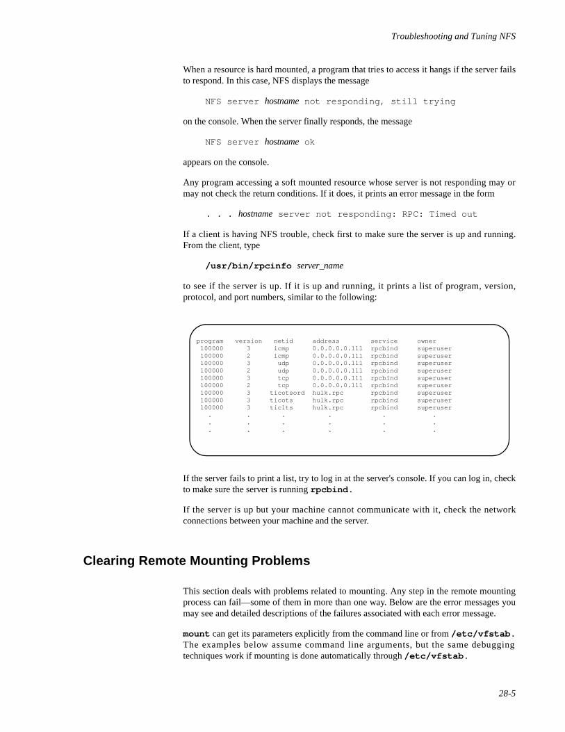
Troubleshooting and Tuning NFS
28-5
When a resource is hard mounted, a program that tries to access it hangs if the server failsto respond. In this case, NFS displays the message
NFS server hostname not responding, still trying
on the console. When the server finally responds, the message
NFS server hostname ok
appears on the console.
Any program accessing a soft mounted resource whose server is not responding may ormay not check the return conditions. If it does, it prints an error message in the form
. . . hostname server not responding: RPC: Timed out
If a client is having NFS trouble, check first to make sure the server is up and running.From the client, type
/usr/bin/rpcinfo server_name
to see if the server is up. If it is up and running, it prints a list of program, version,protocol, and port numbers, similar to the following:
If the server fails to print a list, try to log in at the server's console. If you can log in, checkto make sure the server is running rpcbind.
If the server is up but your machine cannot communicate with it, check the networkconnections between your machine and the server.
Clearing Remote Mounting Problems 28
This section deals with problems related to mounting. Any step in the remote mountingprocess can fail—some of them in more than one way. Below are the error messages youmay see and detailed descriptions of the failures associated with each error message.
mount can get its parameters explicitly from the command line or from /etc/vfstab.The examples below assume command line arguments, but the same debuggingtechniques work if mounting is done automatically through /etc/vfstab.
program version netid address service owner 100000 3 icmp 0.0.0.0.0.111 rpcbind superuser 100000 2 icmp 0.0.0.0.0.111 rpcbind superuser 100000 3 udp 0.0.0.0.0.111 rpcbind superuser 100000 2 udp 0.0.0.0.0.111 rpcbind superuser 100000 3 tcp 0.0.0.0.0.111 rpcbind superuser 100000 2 tcp 0.0.0.0.0.111 rpcbind superuser 100000 3 ticotsord hulk.rpc rpcbind superuser 100000 3 ticots hulk.rpc rpcbind superuser 100000 3 ticlts hulk.rpc rpcbind superuser . . . . . . . . . . . . . . . . . .
Network Administration
28-6
• mount: . . . server not responding: RPC:Program notregistered
Either the server sharing the resource you are trying to mount is down, or is at thewrong init state, or its rpcbind is dead or hung, or mount got through torpcbind, but the NFS mount daemon mountd is not registered. You can checkthe server's init state by entering (at the server) the following command:
who -r
If the server is at init state 3, try going to another init state and back, or try rebootingthe server to restart rpcbind. Try to log in to the server from your machine, usingthe rlogin command. If you can't log in, but the server is up, try to log in toanother remote machine to check your network connection. If that connection isworking, check the server's network connection. See who(1) for more informationon the who command. If mountd is not running, try restarting NFS. See “Startingand Stopping NFS Operation” on page 25-2 for information on restarting NFS.
• mount: . . . : No such file or directory
Either the remote directory or the local directory does not exist. Check the spellingof the directory names. Use ls on both directories.
• mount: not in share list for . . .
Your machine name is not in the list of clients allowed access to the resource youwant to mount. From the client, you can display the server's share list by entering thefollowing command:
dfshares -F nfs server
If the resource you want is not in the list, log in to the server and run the sharecommand without options.
• mount: . . . : Permission denied
This message indicates that the user does not have the appropriate permissions orthat some authentication failed on the server. It may be that you are not in the sharelist (see the preceding error message and explanation), or that the server could notverify that you are who you say you are. Check the server's /etc/dfs/sharetabfile.
• mount: . . . : Not a directory
The local path is not a directory. Check the spelling in your command, and try to runls on both directories.
• mount: mount-point does not exist.
The local directory where the resource in being mounted (mount-point) does notexist.
• nfs mount: access denied for host:path
This is similar to the mount: . . . : Permission denied error message.
Troubleshooting and Tuning NFS
28-7
• nfs mount: nfs file system; use host:path
The command used to mount a resource is missing information.
The mount command hangs indefinitely if there are no nfsd daemons running on theNFS server. This happens when there is no /etc/dfs/dfstab file on the server when itenters init state 3. To clear the problem, restart the nfsd daemon by executing thefollowing command:
/usr/lib/nfs/nfsd
If you are mounting resources from a fast server, it is advised that you use the NFS-specific mount options rsize and wsize . These options should be set to rsize=1024and wsize=1024 because fast servers cause data overruns on the ethernet driver on slowclient machines. One symptom of this problem has the following message being written tothe console of the client machines:
RPC: Timed out.
Another symptom of this problem may be that the client machine appears to be hung, withthe following message being written to the console of the client machine:
NFS server hostname not responding, still trying
Fixing Hung Programs 28
If programs hang while doing file-related work, your NFS server may be dead. You maysee the following message on your console:
NFS server hostname not responding, still trying
This message indicates that NFS server hostname is down, or that there is a problem withthe server or with the network.
If your machine hangs completely, check the server(s) from which you mounted theresource. If one or more are down, do not be concerned. When the server comes back up,programs resume automatically. No files are destroyed if the resource was hard mounted.
If you soft mount a resource and the server dies, other work should not be affected.Programs that time out trying to access soft mounted remote files will fail with errnoETIMEDOUT, but you should still be able to access other resources.
If all servers are running, ask someone else using these same servers if they are havingtrouble. If more than one machine is having problems getting service, there is a problemwith the server. Log in to the server. Use nfsping -o nfsd to see if nfsd is running.Enter ps -ef | grep nfsd a few times to see if nfsd is accumulating CPU time (letsome time pass between each call). If it is not accumulating CPU time, you may be able tokill and then restart nfsd. If this does not work, you have to reboot the server. If nfsd isnot running, it may be that the server has been taken to a init state that does not support filesharing. Use who -r to obtain the server's current init state.
Network Administration
28-8
If other systems seem to be up and running, check your network connection and theconnection of the server.
If programs on the client are hung but the server is up, NFS requests to the server otherthan reads and writes are succeeding, and messages of the form
xdr_opaque: encode FAILED
are appearing on either the client or the server console, you may be requesting more datathan the underlying transport provider can provide. Try remounting the file system usingthe -o rsize= nnn,wsize= nnn options to mount(1M) to restrict the request sizes theclient will generate. The maximum NFS Version 2 rsize and wsize , which is also thedefault, is 8KB. The maximum NFS Version 3 rsize and wsize , which is also thedefault, is 32KB.
Fixing a Machine That Hangs Part Way through Boot 28
If your machine boots normally, then hangs when it tries to mount resourcesautomatically, most likely one or more servers are down. Use init to go to single usermode or to a init state that does not mount remote resources automatically. Then start theappropriate daemons in the background and use the mount command to mount eachresource usually mounted automatically through the /etc/vfstab file. By mountingresources one at a time, you can determine which server is down. To restart a server that isdown or hung, see the preceding section.
If you cannot mount any of your resources, most likely your network connection is bad.
Improving Access Time 28
If access to remote files seems unusually slow, enter the following command:
ps -ef
on the server and look for abnormal (high) execution times for NFS daemon processes tocheck that the access time is not being affected adversely by a runaway daemon. If there isnothing unusual (processes with excessive CPU time) in the display, and other clients aregetting good response, make sure your biod daemons are running. At the client, type thefollowing command:
ps -ef | grep biod
Look for biod daemons in the display, then enter the command again. If the biods donot accumulate excessive CPU time, they are probably hung. If they are dead or hung,follow these steps:
1. Kill the daemon processes by determining their process ID (pid) numbers:
ps -ef | grep biod
Troubleshooting and Tuning NFS
28-9
The second field contains the pid number. Then enter the following command:
kill -9 pid
where pid is the process ID of the biod daemon.
2. Restart the biod daemon by typing:
/usr/lib/nfs/biod
If biod is running, check your network connection. The netstat -i command canhelp you determine if you are dropping packets; for more information, seenetstat(1M).
Tuning NFS Tunable Parameters 28
To maximize your system resources, you can modify the following NFS tunableparameters in the /etc/conf/cf.d/stune file. Note that the stune file should notbe edited directly. To change the value of a parameter in the stune file, you can use theconfig(1M) program. For more information about modifying parameters in the stunefile, see the chapter “Tunable Parameters” in the guide System Administration. You mayalso want to refer to the stune(4) manual page.
NRNODE Specifies the maximum number of rnode structures to be allocated for NFS.An rnode is a node specific to the NFS file system type. The default is 300nodes.
NFS_ASYNC_MAXSpecifies the maximum number of Light Weight Processes (LWPs) which canbe created for asynchronous I/O over NFS. The default value of 8 LWPs isexpected to be sufficient for most systems.
NFS_ASYNC_TIMEOUTSpecifies, in seconds, the time-to-live of the Light Weight Processes (LWPs)which do asynchronous I/O over NFS. If an asynchronous request is notgenerated in the system in NFS_ASYNC_TIMEOUT seconds, the LWPs exit.The default is 4 seconds.
NFS_MMAP_TIMEOUTSpecifies, in seconds, the interval between the time the NFS mmap LWPwakes up and the time the NFS mmap LWP updates file attributes for llmmaped files. The default is 30 seconds. Given the large amount of CPU timethe mmap LWP can potentially consume, in cases where a significant numberof files have been mmaped over NFS, this value should not be made too small.
NFS_MAXCLIENTSSpecifies the number of active RPC client handles which NFS can cache. Thedefault is 6 clients. This number should be increased only in cases when morememory is added to the system.
NFSD_TIMEOUTSpecifies, in seconds, the time-to-live of the Light Weight Processes (LWPs)
Network Administration
28-10
which service NFS requests from clients. If an NFS request is not received bythe system in NFSD_TIMEOUT seconds, the LWPs exit. The default is 8seconds.
NFSD_MAXSpecifies the maximum number of Light Weight Processes (LWPs) which canbe created for servicing NFS requests from clients. The default is 8 LWPs. Fordedicated NFS servers, this value should be increased.
NFSD_MINSpecifies the minimum number of Light Weight Processes (LWPs) whichshould always exist in the system for servicing NFS requests from NFSclients. The default is 2 LWPs. For dedicated NFS servers, this value shouldbe increased.
NFS_RETRIESSpecifies the maximum number of NFS retries before failing the NFSoperation for a soft mount. The default is 5 retries. Typically, this value shouldnot be changed.
NFS_TIMEOSpecifies, in seconds, the maximum initial time to wait for an NFS server torespond to a client request. The default is 10 seconds. On machines connectedto “lossy” networks (networks where packets tend to get lost), this valueshould be changed. On some “lossy” networks you will have greater successgetting the packet if you retry earlier; on other networks, you will have greatersuccess if you wait longer.
NFS_NRA Specifies the number of pages to read ahead for each read operation, ifpossible. The default is 1 page. Read-ahead over NFS may be turned off bychanging this value to 0.
29Setting Up Secure NFS
Introduction to Secure NFS . . . . . . . . . . . . . . . . . . . . . . . . . . . . . . . . . . . . . . . . . . . . 29-1An Overview of Secure RPC . . . . . . . . . . . . . . . . . . . . . . . . . . . . . . . . . . . . . . . . . . . 29-1
DES Authentication . . . . . . . . . . . . . . . . . . . . . . . . . . . . . . . . . . . . . . . . . . . . . . 29-2A Secure RPC Client/Server Session . . . . . . . . . . . . . . . . . . . . . . . . . . . . . . . . . 29-3
Administering Secure NFS . . . . . . . . . . . . . . . . . . . . . . . . . . . . . . . . . . . . . . . . . . . . 29-5Important Considerations . . . . . . . . . . . . . . . . . . . . . . . . . . . . . . . . . . . . . . . . . . . . . 29-7

Network Administration
29-1
29Chapter 29Setting Up Secure NFS
292929
Introduction to Secure NFS 29
NFS is a powerful and convenient way to share resources on a network of differentmachine architectures and operating systems. However, the same features that makesharing resources through NFS convenient also pose some security problems. An NFSserver authenticates a file request by authenticating the machine making the request, butnot the user.
When the Enhanced Security Utilities are installed, NFS supports the Enhanced Securityfeatures, including Mandatory Access Control (MAC) and the Least Privilege Mechanism(LPM). On a server running MAC and LPM, a client process is allowed access toresources at the same security level, but the user, by default, is granted no privileges tooverride security restrictions. Privileges granted to the user on the client side are notfiltered to the server.
Systems that are not running MAC and LPM do not place similar restrictions on a userprocess. If superuser privilege is not restricted when a resource is shared, a client usercould run su and impersonate the owner of a file.
Systems should take advantage of an authentication mechanism provided with NFS. Theauthentication system exists at the level of Remote Procedure Call (RPC)—themechanism on which NFS is built. The system, known as Secure RPC, greatly improvesthe security of network environments and provides additional security to NFS. Thesecurity features that Secure RPC provides to NFS are known collectively as Secure NFS.
Because Secure RPC is at the core of Secure NFS, it is necessary to understand howauthentication works in RPC to understand Secure NFS. This chapter first presents anoverview of Secure RPC, then tells you how to set up Secure NFS. Following the set upprocedure are a few important points you should be aware of if you plan to use SecureNFS.
An Overview of Secure RPC 29
The goal of Secure RPC is to build a system at least as secure as a normal time-sharingsystem. The way a user is authenticated in a time-sharing system is through a login pass-word. With Data Encryption Standard (DES) authentication, the same is true. Users canlog in on any remote machine, just as they can on a local terminal, and their login pass-words are used for authentication on the remote machines. For time-sharing systems, thetrusted person is the system administrator, who has an ethical obligation not to change a
Network Administration
29-2
password in order to impersonate someone. In secure RPC, the network administrator istrusted not to alter entries in a database that stores “public keys.
You need to be familiar with two terms to understand an RPC authentication system:credentials and verifiers. Using ID badges as an example, the credential is what identifiesa person: a name, address, birth date, and so on. The verifier is the photo attached to thebadge: you can be sure the badge has not been stolen by checking the photo on the badgeagainst the person carrying it. In RPC, the client process sends both credentials and averifier to the server with each RPC request. The server sends back only a verifier, sincethe client already knows the server's credentials. If the server doesn't recognize the client'scredentials, the server sends back an error message stating that the client sent invalidcredentials.
RPC's authentication is open-ended, which means that a variety of authentication systemsmay be plugged into it. Currently, there are two such systems: the UNIX system, and theData Encryption Standard (DES) system.
When the UNIX system authentication is used by a network service, the credentialscontain the client's machine-name, UID, gid, and group-access-list, but the verifiercontains nothing. This presents a problem. Because there is no verifier, users could deduceappropriate credentials. Another problem with UNIX system authentication is that itassumes all machines on a network are UNIX system machines. UNIX systemauthentication breaks down when applied to other operating systems in a heterogeneousnetwork.
To overcome the problems of UNIX system authentication, Secure RPC uses DESauthentication—a scheme that employs verifiers, yet allows Secure RPC to be generalenough to be used by most operating systems.
DES Authentication 29
DES authentication uses the Data Encryption Standard (DES) and public keycryptography to authenticate both users and machines in the network. DES is a standardencryption mechanism; public key cryptography is a cipher system that involves two keys:one public and one private.
The security of DES authentication is based on a sender's ability to encrypt the currenttime, which the receiver can then decrypt and check against its own clock. The timestampis encrypted with DES. Two things are necessary for this scheme to work: 1) the twoagents must agree on the current time, and 2) the sender and receiver must be using thesame encryption key.
If a network runs a time synchronization program, then the time on the client and theserver is synchronized automatically. If a time synchronization program is not available,timestamps can be computed using the server's time instead of the network time. Theclient asks the server for the time before starting the RPC session, then computes the timedifference between its own clock and the server's. This difference is used to offset theclient's clock when computing timestamps. If the client and server clocks get out of syncto the point where the server begins to reject the client's requests, the DES authenticationsystem resynchronizes with the server.
The client and server arrive at the same encryption key by generating a randomconversation key, then using public key cryptography to deduce a common key. The com-
Setting Up Secure NFS
29-3
mon key is a key that only the client and server are capable of deducing. The conversationkey is used to encrypt and decrypt the client's timestamp; the common key is used toencrypt and decrypt the conversation key.
A Secure RPC Client/Server Session 29
Here is the series of transactions effected in a client/server session using Secure RPC.
Step 1 Sometime prior to a transaction, the user runs a program that generates apublic key and a secret key. (Each user has a unique public key and secret key.)The public key is stored, in encrypted form, in a public database; the secretkey is stored, also in encrypted form, in a private database.
Step 2 The user logs in and runs the keylogin program (or the keyloginprogram may be included in $HOME/profile so that it runs automaticallywhenever the user logs in). The keylogin program prompts the user for asecure RPC password and uses the password to decrypt the secret key. Thekeylogin program then passes the decrypted secret key to a program calledthe Keyserver. (The Keyserver is an RPC service with a local instance onevery machine.) The Keyserver saves the decrypted secret key, and waits forthe user to initiate a transaction with a server.
Step 3 When the user initiates a transaction with a server
a. the Keyserver randomly generates a conversation key.
b. the kernel uses the conversation key to encrypt the client'stimestamp (among other things).
c. the Keyserver looks up the server's public key in the publicdatabase.
d. the Keyserver uses the client's secret key and the server's publickey to create a common key.
e. the Keyserver encrypts the conversation key with the commonkey.
Step 4 The transmission including the timestamp and the conversation key is thensent to the server. The transmission includes a credential and a verifier. Thecredential contains three things:
• the client's machine name.
• the conversation key, encrypted with the common key.
• a “window,” encrypted with the conversation key.
The window is the difference the client says should be allowed betweenthe server's clock and the client's timestamp. If the difference betweenthe server's clock and the timestamp is greater than the window, theserver should reject the client's request. (For secure NFS, the windowcurrently defaults to 30 minutes.)
Network Administration
29-4
The client's verifier contains
• the encrypted timestamp.
• an encrypted verifier of the specified window, incremented by1
The reason the window verifier is needed is this: Suppose somebodywants to impersonate a user and writes a program that, instead of fillingin the encrypted fields of the credential and verifier, just stuffs inrandom bits. The server will decrypt the conversation key into some ran-dom key, and use it to try to decrypt the window and the timestamp. Theresult will just be random numbers. After a few thousand trials, how-ever, there is a good chance that the random window/timestamp pair willpass the authentication system. The window verifier makes guessing theright credential much more difficult.
Step 5 When the server receives the transmission from the client
1. the Keyserver local to the server looks up the client's publickey in the public database.
2. the Keyserver uses the client's public key and the server's secretkey to deduce the common key—the same common keycomputed by the client. (No one but the server and the clientcan calculate the common key, since doing so requiresknowing one secret key or the other.)
3. the kernel uses the common key to decrypt the conversationkey.
4. the kernel calls the Keyserver to decrypt the client's timestampwith the decrypted conversation key.
Step 6 After the server decrypts the client's timestamp, it stores four things in acredential table:
• the client's machine name.
• the conversation key.
• the window.
• the client's timestamp.
The server stores the first three things for future use. It stores thetimestamp to protect against replays. The server will only accepttimestamps that are chronologically greater than the last one seen, soany replayed transactions are guaranteed to be rejected.
Step 7 The server returns a verifier to the client, which includes
• the index ID, which the server records in its credential table.
• the client's timestamp minus one, encrypted by conversationkey.
Setting Up Secure NFS
29-5
The reason for subtracting one from the timestamp is to insure that it isinvalid and cannot be reused as a client verifier.
Step 8 The client receives the verifier and authenticates the server. The client knowsthat only the server could have sent the verifier, since only the server knowswhat timestamp the client sent.
Step 9 The client returns the index ID to the server in its second transaction and sendsanother encrypted timestamp.
Step 10 The server sends back the client's timestamp minus 1, encrypted by theconversation key.
With every transaction after the first, the client sends its index ID and another encryptedtimestamp, and the server returns the timestamp minus 1.
NOTE
Implicit in these procedures is the name of caller, who must beauthenticated in some manner. The Keyserver cannot use DESauthentication to do this, since it would create a deadlock. TheKeyserver solves this problem by storing the secret keys by UID,and only granting requests to local root processes. The clientprocess then executes a set-UID process, owned by root, whichmakes the request on the part of the client, telling the Keyserverthe real UID of the client.
Administering Secure NFS 29
To use Secure NFS, all the machines for which you are responsible must have a domainname. A domain is an administrative entity, typically consisting of several machines, thatjoins a larger network. If you are running the Network Information Service (NIS), youshould also establish the NIS name service for the domain. See Chapter 34, "NetworkInformation Service Administration" for information on setting up NIS.
With UNIX system authentication, the name of a domain is the UID. UIDs are assignedper domain. A problem with this scheme is that UIDs clash when domains are linkedacross the network. Another problem with UNIX system authentication has to do withsuperusers; with UNIX system authentication, the superuser ID (uid 0) is assigned one permachine, not one per domain, which means that a domain can have multiple superusers—all with the same uid.
DES authentication corrects these problems by using netnames. A netname is simply astring of printable characters created by concatenating the name of the operating system, auser ID, and a domain name. For example, a UNIX system user with a user ID of 508 inthe domain eng.acme.COM would be assigned the fo l lowing netname:[email protected]. Because user IDs are unique within a domain, andbecause domain names are unique on a network, this scheme produces a unique netnamefor every user.
Network Administration
29-6
To overcome the problem of multiple super-users per domain, netnames are assigned tomachines as well as to users. A machine's netname is formed much like a users—by con-catenating the name of the operating system and the machine name with the domain name.A UNIX system machine named hal in the domain eng.acme.COM would have the net-name [email protected].
1. Assign your domain a domain name by following the instructions inChapter 12, "Setting Up TCP/IP", and make the domain name known toeach machine in the NIS/RPC domain by using domainname on eachmachine. See “The SRPC_DOMAIN Variable” on page 33-3 for furtherinformation on domainname .
2. Either establish public keys and secret keys for your clients' users using thenewkey command, or have each user establish their own public and secretkeys using the chkey command.
When public and secret keys have been generated, the public keys arestored in the publickey database, and users' secret keys are stored in/etc/keystore. Secret keys for root users are stored in /etc/.rootkey.
NOTE
For information about these commands, see newkey(1M) andthe chkey(1).
3. If you choose, put the keylogin program in /etc/profile so that itruns automatically whenever a user logs in. Otherwise, make sure usersknow to run keylogin when they log in.
4. If you are running NIS, verify that the ypbind daemon is running and thatthere is a ypserv running in the domain.
5. Verify that the keyserv daemon (the Keyserver) is running by typing
ps -ef | grep keyserv
If it isn't running, start the Keyserver by typing
/usr/sbin/keyserv
6. Edit the /etc/dfs/dfstab file and add the secure option to theappropriate entries (those that indicate resources you want clients to mountusing DES authentication).
7. On each client machine, edit /etc/vfstab to include secure as amount option in the appropriate entries (those that indicate resources thatshould be mounted using DES authentication).
Setting Up Secure NFS
29-7
NOTE
If a client does not mount as secure a resource that is shared assecure, everything works, but users have access as user nobody,rather than as themselves.
If you are not running NIS, all users must keep their secret keys synchronized with theirlogin passwords by invoking chkey if they change their entries in the password database.
When you reinstall, move, or upgrade a machine, remember to save /etc/keystoreand /etc/.rootkey.
Important Considerations 29
The following are points you should be aware of if you plan to use Secure RPC:
• If a server crashes when no one is around (after a power failure forexample), all of the secret keys that are stored on the system are wiped out.Now no process is able to access secure network services, or mount an NFSfile system. The important processes at this time are usually root processes,so things would work if root's secret key were stored away, but nobody isaround to type the password that decrypts it. If the machine has a localdisk, the solution to the problem is to store root's decrypted secret key in afile, which the Keyserver can read.
• Some systems boot in single-user mode, with a root login shell on theconsole and no password prompt. Physical security is imperative in suchcases.
• A problem with diskless clients is that diskless machine booting is nottotally secure. It is possible for somebody to impersonate the boot-server,and boot a devious kernel that, for example, makes a record of your secretkey on a remote machine. Secure NFS provides protection only after thekernel and the Keyserver are running. Before that, there is no way toauthenticate the replies given by the boot server. This is not considered aserious problem, because it is highly unlikely that somebody would be ableto write this compromised kernel without source code. Also, the crime isnot without evidence. If you polled the network for boot-servers, youwould discover the devious boot-server's location.
• Most set-UID programs are owned by root; since root's secret key is alwaysstored at boot time, these programs will behave as they always have. If aset-UID program is owned by a user, however, it may not always work. Forexample, if a set-UID program is owned by dave, and dave has notlogged into the machine since it booted, then the program would not beable to access secure network services.
• If you log in to a remote machine (using login, rlogin, or telnet)and use keylogin to gain access, you give away access to your account.This is because your secret key gets passed to that machine's Keyserver,which then stores it. This is only a concern if you don't trust the remote

Network Administration
29-8
machine. If you have doubts, however, don't log in to a remote machine if itrequires a password. Instead, use NFS to mount resources shared by theremote machine. If you used keylogin to gain access, you should usekeylogout(1) (for security reasons) on the machine where keyloginwas executed to remove your unencrypted secret key from the Keyserver'saddress space.
• Using secure NFS can result in some degrading of performance. However,that is the impact on network performance. Not all file operations go overthe network, so the impact on total system performance is actually lower.Secure NFS is an optional feature; environments that require higherperformance at the expense of security can turn it off.
30Using the NFS Automounter
The NFS Automounter . . . . . . . . . . . . . . . . . . . . . . . . . . . . . . . . . . . . . . . . . . . . . . . 30-1How the Automounter Works . . . . . . . . . . . . . . . . . . . . . . . . . . . . . . . . . . . . . . . . . . 30-1Preparing the Automounter Maps . . . . . . . . . . . . . . . . . . . . . . . . . . . . . . . . . . . . . . . 30-2Conventions . . . . . . . . . . . . . . . . . . . . . . . . . . . . . . . . . . . . . . . . . . . . . . . . . . . . . . . . 30-2
Writing a Master Map . . . . . . . . . . . . . . . . . . . . . . . . . . . . . . . . . . . . . . . . . . . . 30-3Writing a Direct Map . . . . . . . . . . . . . . . . . . . . . . . . . . . . . . . . . . . . . . . . . . . . . 30-4Writing an Indirect Map . . . . . . . . . . . . . . . . . . . . . . . . . . . . . . . . . . . . . . . . . . . 30-5
Example of an Indirect Map . . . . . . . . . . . . . . . . . . . . . . . . . . . . . . . . . . . . 30-5Specifying Multiple Mounts. . . . . . . . . . . . . . . . . . . . . . . . . . . . . . . . . . . . . . . . 30-6Specifying Multiple Locations . . . . . . . . . . . . . . . . . . . . . . . . . . . . . . . . . . . . . . 30-7Specifying Subdirectories. . . . . . . . . . . . . . . . . . . . . . . . . . . . . . . . . . . . . . . . . . 30-8Using Substitutions. . . . . . . . . . . . . . . . . . . . . . . . . . . . . . . . . . . . . . . . . . . . . . . 30-9Using Environment Variables . . . . . . . . . . . . . . . . . . . . . . . . . . . . . . . . . . . . . . . 30-10
Invoking the Automounter. . . . . . . . . . . . . . . . . . . . . . . . . . . . . . . . . . . . . . . . . . . . . 30-11Killing the Automounter . . . . . . . . . . . . . . . . . . . . . . . . . . . . . . . . . . . . . . . . . . . . . . 30-12Updating the Mount Table . . . . . . . . . . . . . . . . . . . . . . . . . . . . . . . . . . . . . . . . . . . . . 30-13Modifying the Maps . . . . . . . . . . . . . . . . . . . . . . . . . . . . . . . . . . . . . . . . . . . . . . . . . 30-13
Modifying Master and Direct Maps . . . . . . . . . . . . . . . . . . . . . . . . . . . . . . . . . . 30-13Modifying Indirect Maps . . . . . . . . . . . . . . . . . . . . . . . . . . . . . . . . . . . . . . . . . . 30-13
Troubleshooting the Automounter. . . . . . . . . . . . . . . . . . . . . . . . . . . . . . . . . . . . . . . 30-14

Network Administration
30-1
30Chapter 30Using the NFS Automounter
303030
The NFS Automounter 30
Resources shared through NFS can be mounted using a method called “automounting.”The automount program (located in /usr/lib/nfs/automount ) mounts andunmounts remote directories on an as-needed basis. Whenever a user on a client runningthe automounter invokes a command that needs to access a remote file, the shared resourceto which that file belongs is mounted automatically. When a certain amount of time haselapsed without the resource being accessed, it is automatically unmounted. For additionalinformation on automount , see automount(1M).
Once the automounter is invoked, an administrator does not have to set up automaticmounting with the vfstab file, or use the mount and umount commands at thecommand line. All mounting is done automatically and transparently.
NOTE
Mounting some resources with automount does not exclude thepossibility of mounting others with mount ; in fact, in a disklessmachine you must mount root (/ ) and /usr with mount .
This chapter explains how the automounter works and provides instructions for setting itup.
How the Automounter Works 30
Unlike mount, automount does not consult the file /etc/vfstab for a list ofresources to mount automatically. Rather, it consults a series of maps. These maps enablethe automounter to locate the appropriate NFS file server, the exported file system, and themount options for the requested resource.
The automounter mounts everything under the directory /tmp_mnt, and provides a sym-bolic l ink from the requested mount point to the actual mount point under/tmp_mnt. For instance, if a user wants to mount a remote directory src under /usr/src, the actual mount point will be /tmp_mnt/usr/src, and /usr/src will be asymbolic link to that location.
When automount is called, it forks a daemon (automountd ) to serve each mount pointin the maps and makes the kernel believe that the mount has taken place. The daemon
Network Administration
30-2
sleeps until a request is made to access the corresponding resource. In the mount state, thedaemon intercepts the request, mounts the remote resource, creates a symbolic linkbetween the requested mount point and the actual mount point under /tmp_mnt, passesthe symbolic link to the kernel, and steps aside.
When a predetermined amount of time has passed with the link not being touched(generally five minutes), the daemon unmounts the resource and resumes its previousposition.
Preparing the Automounter Maps 30
A server never knows, nor cares, whether the files it shares are accessed through mount orautomount. Nothing, therefore, needs to be done to a server to run the automounter.
A client, however, needs special files for the automounter. As mentioned earlier, auto-mount does not consult /etc/vfstab; rather, it consults a map file (or files) specifiedat the command line.
There are three basic kinds of automounter maps:
• a master map
• a direct map
• an indirect map
The master map is a general map that uses other maps that contain more specificinformation. When you enter a command to invoke the automounter and you specify themaster map, the master map is used to reference direct and indirect maps and get theinformation it needs to give to the automount command.
A direct map contains all the information automount needs to do the mount. It can becalled directly by the automounter, or through a master map.
An indirect map allows you to specify alternate servers for a set of resources. It also allowsyou to specify resources to be mounted as a hierarchy under the same mount point. Theindirect map is called only through a master map, which specifies the mount point onwhich all resources listed in the indirect map should be mounted.
You should create all your automounter maps in your /etc directory, using any supportedtext editor.
Conventions 30
When creating any of the automounter maps, follow these conventions:
• Use a backslash before characters that may confuse the automounter'sparser. For example, suppose you want to mount a directory whose name
Using the NFS Automounter
30-3
includes a colon, such as rc0:dk1. This resource name might result inthe map entry
/junk -ro vmsserver:rc0:dk1
The automounter will be confused by the second colon in this entry. To avoid aproblem, the entry should look like this:
/junk -ro vmsserver:rc0\:dk1
• Use double quotes around a resource name to hide white space.
• If you enter a comment into a map, make sure that it is preceded by #.
• If you include a long entry in a map, use backslashes to split the line intotwo or more shorter lines. For example, the entry
/usr/frame -ro,soft redwood:/usr/frame1.3 balsa:/export/frame
could be written as
/usr/frame -ro,soft redwood:/usr/frame1.3 \balsa:/export/frame
Writing a Master Map 30
Each line in a master map has the syntax:
mountpoint map [ mount-options]
where mountpoint is the full pathname of a directory on which resources should bemounted; map is the name of the map that lists the resources to be mounted and theirlocations; and mount-options is a comma-separated list of options that regulates themounting of the entries mentioned in the map (unless the map entries list other options).
The options that can be specified for mount-options are the same options that can bespecified with the mount command, except for fg and bg. See the NFS-specific mount(1M) manual page for information.
The mountpoint can be any mount point you have created for a remote mount. Here is asample entry in a master map:
/usr/man /etc/libmap -ro
This entry tells the automounter to look in the indirect map /etc/libmap and to mounteverything listed there on /usr/man on the local system. This entry also tells theautomounter to mount resources on /usr/man read-only; however, if libmap indicatesthat a resource should be mounted read-write, it will be mounted read-write.
If the master map calls a direct map, mount-point should be /- . This tells the automounterto mount the entries in a direct map on the mount point(s) specified in that map (thelocation field in a direct map contains a full pathname).
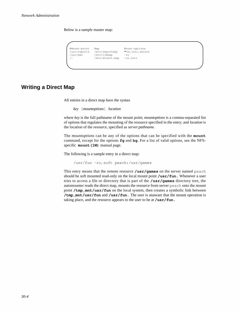
Network Administration
30-4
Below is a sample master map:
Writing a Direct Map 30
All entries in a direct map have the syntax
key [ mountoptions] location
where key is the full pathname of the mount point; mountoptions is a comma-separated listof options that regulates the mounting of the resource specified in the entry; and location isthe location of the resource, specified as server:pathname.
The mountoptions can be any of the options that can be specified with the mountcommand, except for the options fg and bg . For a list of valid options, see the NFS-specific mount(1M) manual page.
The following is a sample entry in a direct map:
/usr/fun -ro,soft peach:/usr/games
This entry means that the remote resource /usr/games on the server named peachshould be soft mounted read-only on the local mount point /usr/fun. Whenever a usertries to access a file or directory that is part of the /usr/games directory tree, theautomounter reads the direct map, mounts the resource from server peach onto the mountpoint /tmp_mnt/usr/fun on the local system, then creates a symbolic link between/tmp_mnt/usr/fun and /usr/fun. The user is unaware that the mount operation istaking place, and the resource appears to the user to be at /usr/fun.
#Mount-point Map Mount-options/usr/reports /etc/reportmap - rw,intr,secure/usr/man /etc/libmap -ro/- /etc/direct.map -ro,intr
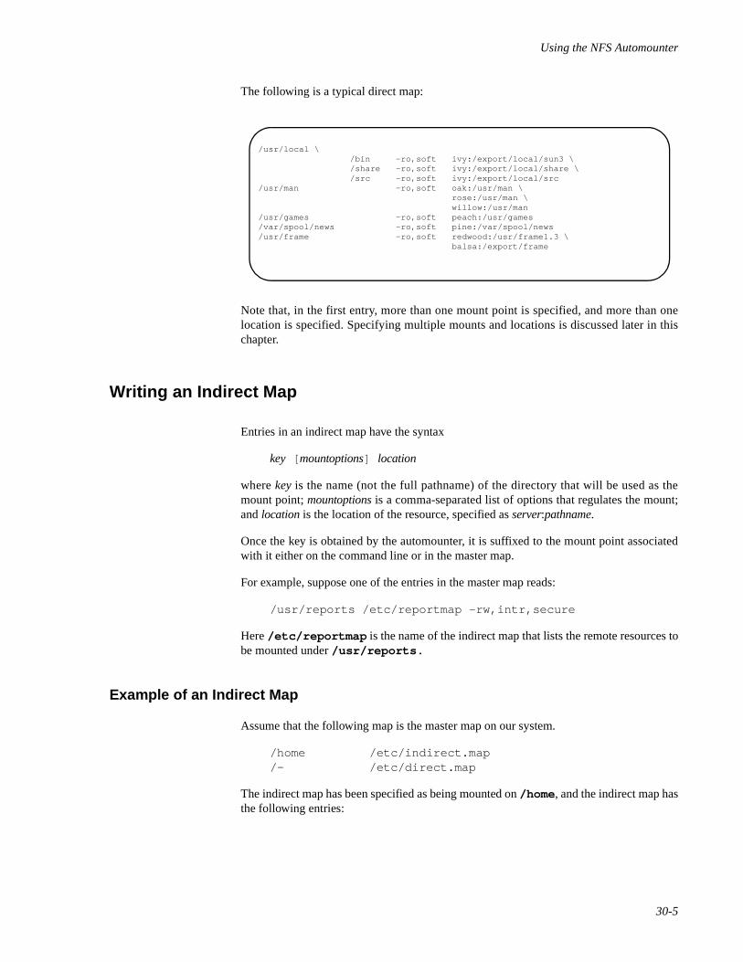
Using the NFS Automounter
30-5
The following is a typical direct map:
Note that, in the first entry, more than one mount point is specified, and more than onelocation is specified. Specifying multiple mounts and locations is discussed later in thischapter.
Writing an Indirect Map 30
Entries in an indirect map have the syntax
key [ mountoptions] location
where key is the name (not the full pathname) of the directory that will be used as themount point; mountoptions is a comma-separated list of options that regulates the mount;and location is the location of the resource, specified as server:pathname.
Once the key is obtained by the automounter, it is suffixed to the mount point associatedwith it either on the command line or in the master map.
For example, suppose one of the entries in the master map reads:
/usr/reports /etc/reportmap -rw,intr,secure
Here /etc/reportmap is the name of the indirect map that lists the remote resources tobe mounted under /usr/reports.
Example of an Indirect Map 30
Assume that the following map is the master map on our system.
/home /etc/indirect.map/- /etc/direct.map
The indirect map has been specified as being mounted on /home , and the indirect map hasthe following entries:
/usr/local \ /bin -ro,soft ivy:/export/local/sun3 \ /share -ro,soft ivy:/export/local/share \ /src -ro,soft ivy:/export/local/src/usr/man -ro,soft oak:/usr/man \ rose:/usr/man \ willow:/usr/man/usr/games -ro,soft peach:/usr/games/var/spool/news -ro,soft pine:/var/spool/news/usr/frame -ro,soft redwood:/usr/frame1.3 \ balsa:/export/frame
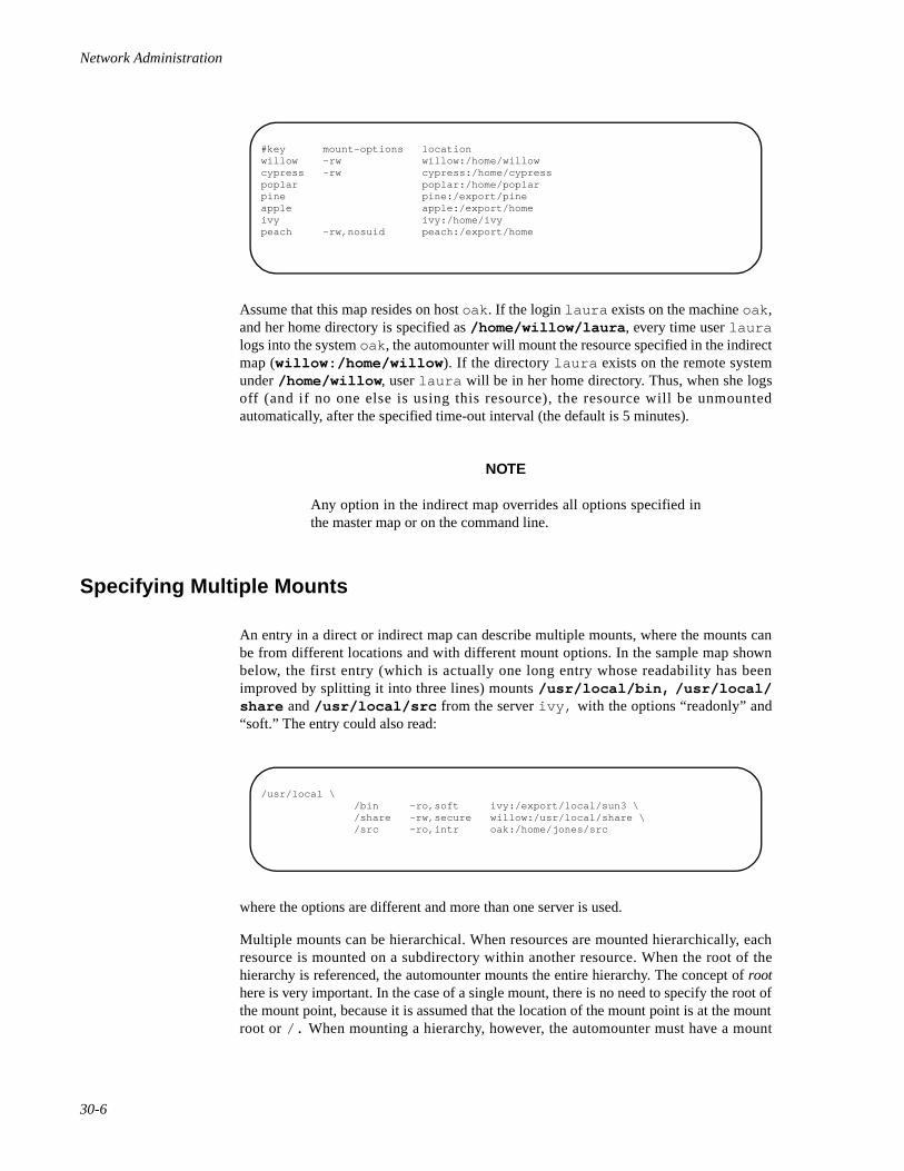
Network Administration
30-6
Assume that this map resides on host oak . If the login laura exists on the machine oak ,and her home directory is specified as /home/willow/laura , every time user lauralogs into the system oak , the automounter will mount the resource specified in the indirectmap (willow:/home/willow ). If the directory laura exists on the remote systemunder /home/willow , user laura will be in her home directory. Thus, when she logsoff (and if no one else is using this resource), the resource will be unmountedautomatically, after the specified time-out interval (the default is 5 minutes).
NOTE
Any option in the indirect map overrides all options specified inthe master map or on the command line.
Specifying Multiple Mounts 30
An entry in a direct or indirect map can describe multiple mounts, where the mounts canbe from different locations and with different mount options. In the sample map shownbelow, the first entry (which is actually one long entry whose readability has beenimproved by splitting it into three lines) mounts /usr/local/bin, /usr/local/share and /usr/local/src from the server ivy, with the options “readonly” and“soft.” The entry could also read:
where the options are different and more than one server is used.
Multiple mounts can be hierarchical. When resources are mounted hierarchically, eachresource is mounted on a subdirectory within another resource. When the root of thehierarchy is referenced, the automounter mounts the entire hierarchy. The concept of roothere is very important. In the case of a single mount, there is no need to specify the root ofthe mount point, because it is assumed that the location of the mount point is at the mountroot or /. When mounting a hierarchy, however, the automounter must have a mount
#key mount-options locationwillow -rw willow:/home/willowcypress -rw cypress:/home/cypresspoplar poplar:/home/poplarpine pine:/export/pineapple apple:/export/homeivy ivy:/home/ivypeach -rw,nosuid peach:/export/home
/usr/local \ /bin -ro,soft ivy:/export/local/sun3 \ /share -rw,secure willow:/usr/local/share \ /src -ro,intr oak:/home/jones/src
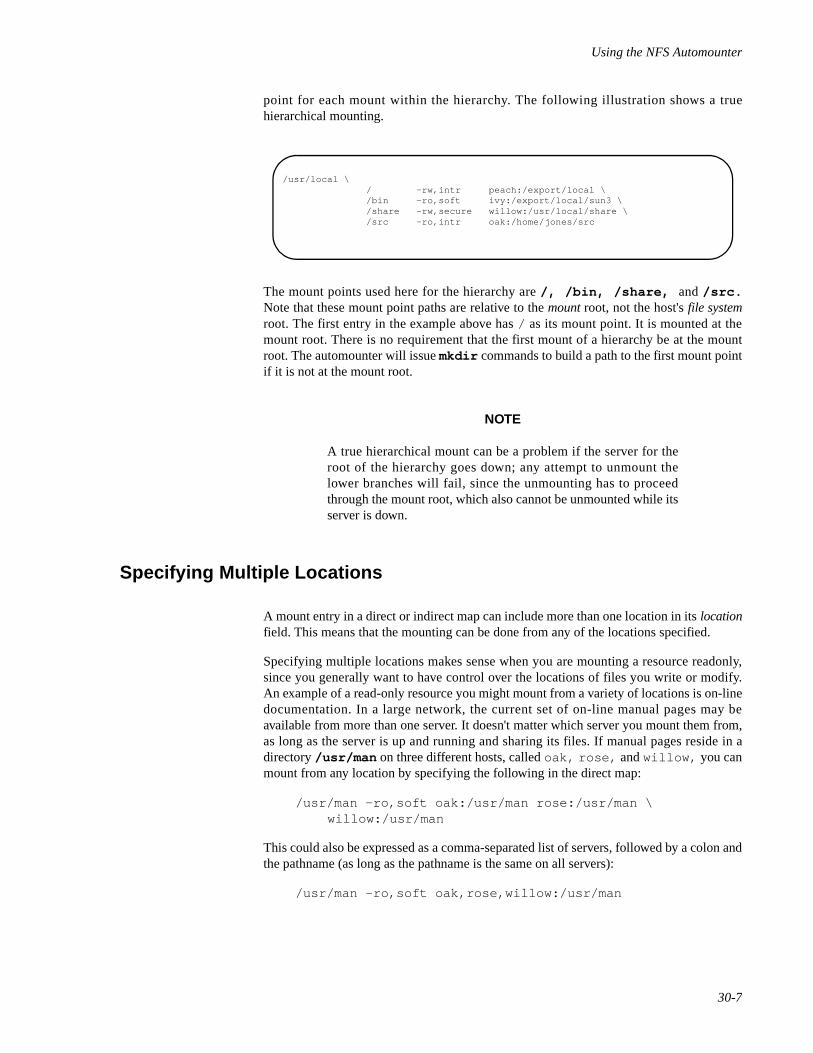
Using the NFS Automounter
30-7
point for each mount within the hierarchy. The following illustration shows a truehierarchical mounting.
The mount points used here for the hierarchy are /, /bin, /share, and /src.Note that these mount point paths are relative to the mount root, not the host's file systemroot. The first entry in the example above has / as its mount point. It is mounted at themount root. There is no requirement that the first mount of a hierarchy be at the mountroot. The automounter will issue mkdir commands to build a path to the first mount pointif it is not at the mount root.
NOTE
A true hierarchical mount can be a problem if the server for theroot of the hierarchy goes down; any attempt to unmount thelower branches will fail, since the unmounting has to proceedthrough the mount root, which also cannot be unmounted while itsserver is down.
Specifying Multiple Locations 30
A mount entry in a direct or indirect map can include more than one location in its locationfield. This means that the mounting can be done from any of the locations specified.
Specifying multiple locations makes sense when you are mounting a resource readonly,since you generally want to have control over the locations of files you write or modify.An example of a read-only resource you might mount from a variety of locations is on-linedocumentation. In a large network, the current set of on-line manual pages may beavailable from more than one server. It doesn't matter which server you mount them from,as long as the server is up and running and sharing its files. If manual pages reside in adirectory /usr/man on three different hosts, called oak, rose, and willow, you canmount from any location by specifying the following in the direct map:
/usr/man -ro,soft oak:/usr/man rose:/usr/man \willow:/usr/man
This could also be expressed as a comma-separated list of servers, followed by a colon andthe pathname (as long as the pathname is the same on all servers):
/usr/man -ro,soft oak,rose,willow:/usr/man
/usr/local \ / -rw,intr peach:/export/local \ /bin -ro,soft ivy:/export/local/sun3 \ /share -rw,secure willow:/usr/local/share \ /src -ro,intr oak:/home/jones/src
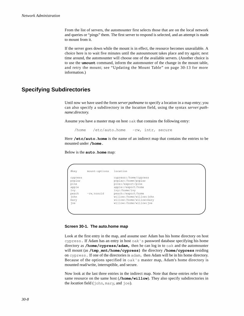
Network Administration
30-8
From the list of servers, the automounter first selects those that are on the local networkand queries or “pings” them. The first server to respond is selected, and an attempt is madeto mount from it.
If the server goes down while the mount is in effect, the resource becomes unavailable. Achoice here is to wait five minutes until the autounmount takes place and try again; nexttime around, the automounter will choose one of the available servers. (Another choice isto use the umount command, inform the automounter of the change in the mount table,and retry the mount; see “Updating the Mount Table” on page 30-13 for moreinformation.)
Specifying Subdirectories 30
Until now we have used the form server:pathname to specify a location in a map entry; youcan also specify a subdirectory in the location field, using the syntax server:path-name:directory.
Assume you have a master map on host oak that contains the following entry:
/home /etc/auto.home -rw, intr, secure
Here /etc/auto.home is the name of an indirect map that contains the entries to bemounted under /home.
Below is the auto.home map:
Screen 30-1. The auto.home map
Look at the first entry in the map, and assume user Adam has his home directory on hostcypress. If Adam has an entry in host oak's password database specifying his homedirectory as /home/cypress/adam, then he can log in to oak and the automounterwill mount (as /tmp_mnt/home/cypress) the directory /home/cypress residingon cypress. If one of the directories is adam, then Adam will be in his home directory.Because of the options specified in oak's master map, Adam's home directory ismounted read/write, interruptible, and secure.
Now look at the last three entries in the indirect map. Note that these entries refer to thesame resource on the same host (/home/willow ). They also specify subdirectories inthe location field (john , mary , and joe ).
#key mount-options location
cypress cypress:/home/cypresspoplar poplar:/home/poplarpine pine:/export/pineapple apple:/export/homeivy ivy:/home/ivypeach -rw,nosuid peach:/export/homejohn willow:/home/willow:johnmary willow:/home/willow:maryjoe willow:/home/willow:joe
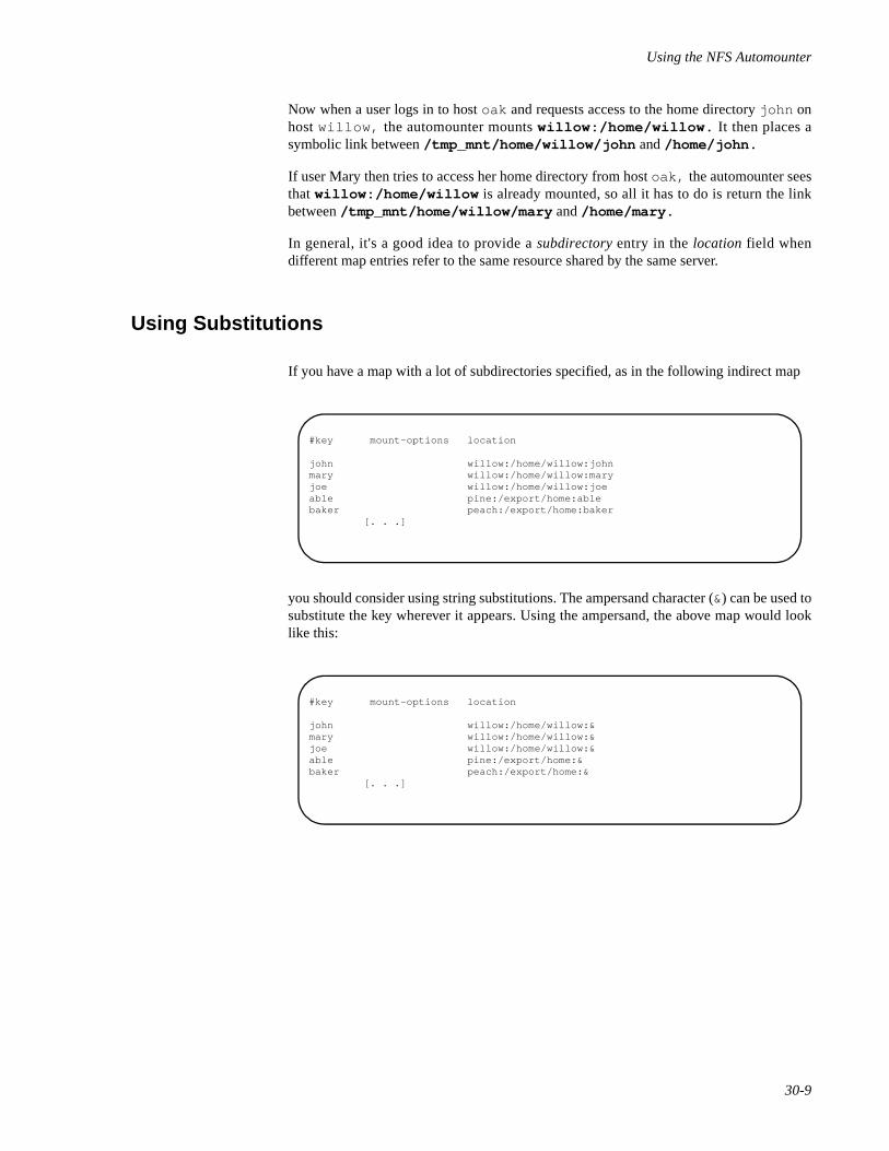
Using the NFS Automounter
30-9
Now when a user logs in to host oak and requests access to the home directory john onhost willow, the automounter mounts willow:/home/willow. It then places asymbolic link between /tmp_mnt/home/willow/john and /home/john.
If user Mary then tries to access her home directory from host oak, the automounter seesthat willow:/home/willow is already mounted, so all it has to do is return the linkbetween /tmp_mnt/home/willow/mary and /home/mary.
In general, it's a good idea to provide a subdirectory entry in the location field whendifferent map entries refer to the same resource shared by the same server.
Using Substitutions 30
If you have a map with a lot of subdirectories specified, as in the following indirect map
you should consider using string substitutions. The ampersand character (&) can be used tosubstitute the key wherever it appears. Using the ampersand, the above map would looklike this:
#key mount-options location
john willow:/home/willow:johnmary willow:/home/willow:maryjoe willow:/home/willow:joeable pine:/export/home:ablebaker peach:/export/home:baker [. . .]
#key mount-options location
john willow:/home/willow:&mary willow:/home/willow:&joe willow:/home/willow:&able pine:/export/home:&baker peach:/export/home:& [. . .]
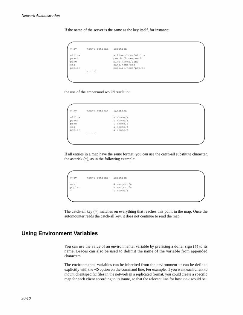
Network Administration
30-10
If the name of the server is the same as the key itself, for instance:
the use of the ampersand would result in:
If all entries in a map have the same format, you can use the catch-all substitute character,the asterisk (* ), as in the following example:
The catch-all key (* ) matches on everything that reaches this point in the map. Once theautomounter reads the catch-all key, it does not continue to read the map.
Using Environment Variables 30
You can use the value of an environmental variable by prefixing a dollar sign ($) to itsname. Braces can also be used to delimit the name of the variable from appendedcharacters.
The environmental variables can be inherited from the environment or can be definedexplicitly with the -D option on the command line. For example, if you want each client tomount clientspecific files in the network in a replicated format, you could create a specificmap for each client according to its name, so that the relevant line for host oak would be:
#key mount-options location
willow willow:/home/willowpeach peach:/home/peachpine pine:/home/pineoak oak:/home/oakpoplar poplar:/home/poplar [. . .]
#key mount-options location
willow &:/home/&peach &:/home/&pine &:/home/&oak &:/home/&poplar &:/home/& [. . .]
#key mount-options location
oak &:/export/&poplar &:/export/&* &:/home/&
Using the NFS Automounter
30-11
/mystuff cypress,ivy,balsa:/export/hostfiles/oak
and for willow:
/mystuff cypress,ivy,balsa:/export/hostfiles/willow
This scheme is viable within a small network, but maintaining this kind of host-specificmap across a large network usually isn't feasible. The solution in this case would be toinvoke the automounter with a command line similar to the following:
automount -D HOST=`ame -n` . .
and have the entry in the direct map read:
/mystuff cypress,ivy,balsa:/export/hostfiles/$HOST
Now each host would find its own files in the mystuff directory, and the task of centrallyadministering and distributing the maps becomes easier.
Invoking the Automounter 30
Once the maps are written, you should make sure that there are no equivalent entries in/etc/vfstab, and that all the entries in the maps refer to NFS shared resources.
The syntax to invoke the automounter is:
automount [ -mnTv ] [ -D name=value] [ -M mount-directory] \[ -f master-file] [ -t sub-options] [ directory map [ -mount-options]] . . .
See automount(1M) for a complete description of options. The suboptions are thesame as those for NFS mount, with the exception of bg (background) and fg (fore-ground), which do not apply.
The default mount point for all mounts is /tmp_mnt. Like the other names, this is anarbitrary name. It can be changed when you enter the automount command with the -Moption. For example,
automount -M /auto . . .
causes all mounts to happen under the directory /auto, which the automounter creates ifit doesn't already exist.
The automounter can be invoked in one of the following ways:
1. You can specify all arguments to the automounter without reference to themaster map:
automount /net /home /etc/ indirect_map \ -rw ,intr,secure /- /etc/ direct_map -ro ,intr
/net is the directory/mount-point, /home is the mount point for the indirect map,/etc/ indirect_map is the location for the indirect_map that is to be used,-rw ,intr,secure are the mount options for the indirect_map, /- means use a
Network Administration
30-12
direct_map, /etc/ direct_map is the location for the direct_map that is to be used,and -ro ,intr are the mount options for the direct_map.
2. You can specify all arguments in the master map and instruct the auto-mounter to look in it for instructions:
automount -f /etc/ master_map
3. You can specify more mount points and maps in addition to thosementioned in the master map:
automount -f /etc/ master_map /src /etc/auto.src -ro ,soft
4. You can nullify one of the entries in the master map (particularly useful ifyou are using a map that you cannot modify but does not meet the needs ofyour machine):
automount -f /usr/lib/ master_map /home -null
5. You can override an entry in the master map by specifying a different indi-rect map on the command line, as follows:
automount -f /usr/lib/ master_map /home \/myown/ indirect_map -rw ,intr
This command tells the automounter to mount /home according to instructions in/myown/ indirect_map, not according to instructions in the indirect map specified inthe master map.
Killing the Automounter 30
To kill the automounter, first find out the automount 's pid number by entering:
ps -ef | grep automount
The second field contains the pid number. Then enter the following command:
kill pid
where pid is the automount process ID.
NOTE
automount must not be terminated with the SIGKILL signal(kill -9 ). Without an opportunity to unmount itself, auto-mount 's mount points will appear to the kernel as belonging to anon-responding NFS server. The recommended way to terminateautomount services is to send a SIGTERM (kill -15 , thedefault signal) to the daemon. This allows the automounter tocatch the signal, and to unmount not only the mount points associ-ated with its daemon, but also to unmount any mounts in
Using the NFS Automounter
30-13
/tmp_mnt . Note that any mounts in /tmp_mnt that are busywill not be unmounted.
Updating the Mount Table 30
If you use umount to unmount explicitly one of the automounted resources, have theautomounter re-read the /etc/mnttab file to update the internal database used by theautomounter.
This can be accomplished by sending SIGTERM signal to the automount daemon. First,find out the automount 's pid number by entering:
ps -ef | grep automount
The second field contains the pid number. Then enter the following command:
kill pid
where pid is the automount process ID.
Modifying the Maps 30
You can modify the automounter maps at any time.
Modifying Master and Direct Maps 30
The automounter looks at the master and direct maps only when it is invoked. To makechanges to a master map or a direct map take effect, perform the following procedure:
1. Terminate the automount process, following the procedure described inthe section “Killing the Automounter” on page 30-12.
2. Restart the automount process, following the procedure described in thesection “Invoking the Automounter” on page 30-11.
Modifying Indirect Maps 30
You do not have to stop and restart the automounter to make changes to an indirect maptake effect. Changes to an indirect map will take effect the next time the automountermounts the modified entry.
Network Administration
30-14
Troubleshooting the Automounter 30
The following are error messages you may see if the automounter fails.
• mapname: Not found
The required map cannot be located. This message is produced only when the -v(verbose) option is given. Check the spelling and pathname of the map name.
• dir mountpoint must start with '/'
The automounter mount point must be given as full pathname. Check the spellingand pathname of the mount point.
• mountpoint: Not a directory
The mountpoint exists but it is not a directory. Check the spelling and pathname ofthe mount point.
• hierarchical mountpoint: mountpoint
The automounter will not allow itself to be mounted within an automounteddirectory. You will have to think of another strategy.
• WARNING: mountpoint not empty!
The mount point is not an empty directory. This message is produced only when the-v (verbose) option is given, and it is only a warning. All it means is that the previ-ous contents of mountpoint will not be accessible.
• Can't mount mountpoint: reason
The automounter cannot mount itself at mountpoint. The reason should be self-explanatory.
• hostname:filesystem already mounted on mountpoint
The automounter is attempting to mount a resource on a mount point, but theresource is already mounted on that mount point. This happens if an entry in /etc/vfstab is duplicated in an automounter map (either by accident or because the out-put of mount -p was redirected to vfstab). Delete one of the redundant entries.
• WARNING: hostname:filesystem already mounted on mountpoint
The automounter is mounting itself on top of an existing mount point.
• couldn't create directory: reason
The system could not create a directory. The reason should be selfexplanatory.
• bad entry in map mapname “map entry”
The map entry in map mapname is incorrect.
• map mapname, key map key: bad
Using the NFS Automounter
30-15
The map entry is malformed, and the automounter cannot interpret it. Recheck theentry; perhaps there are characters in it that need escaping.
• hostname: exports: rpc_err
There is an error when the automounter tries to get a share list from hostname. Thisindicates a server or network problem.
• host hostname not responding
A resource was trying to be mounted from host hostname while the host was down.
• hostname:filesystem server not responding
A resource that is currently mounted from host hostname (that is down) has beenaccessed.
• Mount of hostname:filesystem on mountpoint: reason
You will see these error messages after the automounter attempts to mount fromhostname but gets no response or fails. This may indicate a server or networkproblem.
• mountpoint - pathname from hostname: absolute symbolic link
When mounting a resource, the automounter has detected that mountpoint is anabsolute symbolic link (beginning with /). The content of the link is pathname.This may have undesired consequences on the client; for example, the content of thelink may be /usr.
• Cannot create socket for broadcast rpc: rpc_err
• Many_cast select problem: rpc_err
• Cannot send broadcast packet: rpc_err
• Cannot receive reply to many_cast: rpc_err
All these error messages indicate problems attempting to “ping” servers for areplicated file system. This may indicate a network problem.
• trymany: servers not responding: reason
No server in a replicated list is responding. This may indicate a network problem.
• Remount hostname:filesystem on mountpoint: server notresponding
An attempted remount after an unmount failed. This indicates a server problem.
• NFS server (pid n@mountpoint) not responding still try-ing
An NFS request made to the automount daemon with PID n serving mountpoint hastimed out. The automounter may be overloaded temporarily, or dead. Wait a fewminutes; if the condition persists, the easiest solution is to reboot the client. If youdon't want to reboot, exit all processes that make use of automounted resources (orchange to a non-automounted resource, in the case of a shell), kill the current auto-

Network Administration
30-16
mount process, and restart it again from the command line. If this fails, you mustreboot.

31The NFS Network Lock Manager
An Overview of the Network Lock Manager . . . . . . . . . . . . . . . . . . . . . . . . . . . . . . 31-1The Locking Protocol . . . . . . . . . . . . . . . . . . . . . . . . . . . . . . . . . . . . . . . . . . . . . 31-3The Network Status Monitor . . . . . . . . . . . . . . . . . . . . . . . . . . . . . . . . . . . . . . . 31-4

Network Administration
31-1
31Chapter 31The NFS Network Lock Manager
313131
An Overview of the Network Lock Manager 31
NFS takes advantage of a network locking facility, accomplished via a user-level daemoncalled the Network Lock Manager. The Lock Manager supports the style of advisory andmandatory file and record locking—provided via lockf() and fcntl(). Mandatoryfile and record locking is not supported over NFS.
Locking prevents multiple processes from modifying the same file at the same time, andallows cooperating processes to synchronize access to shared files. The user interfaceswith the network locking service by way of the standard fcntl() system-call interface,and rarely requires any detailed knowledge of how it works. The kernel maps user calls tothe fcntl() system call or the lockf() library call into RPC-based messages to thelocal lock manager. The fact that the file system may be spread across multiple machinesis really not a complication—until a crash occurs.
All computers crash from time to time, and in an NFS environment, where multiplemachines can have access to the same file at the same time, the process of recovering froma crash is necessarily more complex than in a non-network environment. First of all,locking is inherently stateful (it requires information about locks to be maintained on theserver). If a server crashes, clients with locked files must be able to recover their locks. If aclient crashes, its servers must release the locks held by processes running on the client.Second, to preserve NFS's overall transparency, the recovery of lost locks must not requirethe intervention of the applications themselves. This is accomplished as follows:
• Basic file access operations, such as read and write, use a stateless protocol(the NFS protocol). All interactions between NFS servers and clients areatomic—the server doesn't remember anything about its clients from oneinteraction to the next. In the case of a server crash, client applications willsimply sleep until the server comes back up and their NFS operations cancomplete.
• Stateful services (those that require the server to maintain clientinformation from one transaction to the next), such as the locking service,are not part of the NFS itself. They are separate services that use the statusmonitor to ensure that their implicit network state information remainsconsistent with the real state of the network. There are two specific state-related problems involved in providing the locking in a network context:
1. If the client has crashed, the lock can be held forever by the server.
2. If the server has crashed, it loses its state (including all its lockinformation) when it recovers.
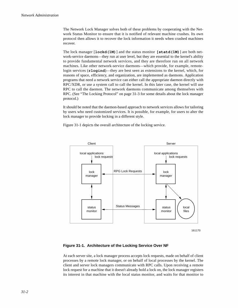
Network Administration
31-2
The Network Lock Manager solves both of these problems by cooperating with the Net-work Status Monitor to ensure that it is notified of relevant machine crashes. Its ownprotocol then allows it to recover the lock information it needs when crashed machinesrecover.
The lock manager [lockd(1M) ] and the status monitor [statd(1M) ] are both net-work-service daemons—they run at user level, but they are essential to the kernel's abilityto provide fundamental network services, and they are therefore run on all networkmachines. Like other network-service daemons—which provide, for example, remote-login services (rlogind )—they are best seen as extensions to the kernel, which, forreasons of space, efficiency, and organization, are implemented as daemons. Applicationprograms that need a network service can either call the appropriate daemon directly withRPC/XDR, or use a system call to call the kernel. In this later case, the kernel will useRPC to call the daemon. The network daemons communicate among themselves withRPC. (See “The Locking Protocol” on page 31-3 for some details about the lock managerprotocol.)
It should be noted that the daemon-based approach to network services allows for tailoringby users who need customized services. It is possible, for example, for users to alter thelock manager to provide locking in a different style.
Figure 31-1 depicts the overall architecture of the locking service.
Figure 31-1. Architecture of the Locking Service Over NF
At each server site, a lock manager process accepts lock requests, made on behalf of clientprocesses by a remote lock manager, or on behalf of local processes by the kernel. Theclient and server lock managers communicate with RPC calls. Upon receiving a remotelock request for a machine that it doesn't already hold a lock on, the lock manager registersits interest in that machine with the local status monitor, and waits for that monitor to
lockmanager
local applicationslock requests
statusmonitor
statusmonitor
161170
lockmanager
ServerClient
local applications
RPG Lock Requests
Status Messages
lock requests
localfiles
The NFS Network Lock Manager
31-3
notify it that the machine is up. The monitor continues to watch the status of registeredmachines, and notifies the lock manager if one of them is rebooted (after a crash). If thelock request is for a local file, the lock manager tries to satisfy it, and communicates backto the application along with the appropriate RPC path.
The crash recovery procedure is very simple. If the failure of a client is detected, the serverreleases the failed client's locks, on the assumption that the client application will requestlocks again as needed. If the recovery (and, by implication, the crash) of a server isdetected, the client lock manger retransmits all the lock requests previously granted by therecovered server. This retransmitted information is used by the server to reconstruct itslocking state.
The locking service, then, is essentially stateless. Or to be more precise, its stateinformation is carefully circumscribed within a pair of system daemons that are set up forautomatic, application-transparent crash recovery. If a server crashes, and thus loses itsstate, it expects that its clients will be notified of the crash and that they will send it theinformation it needs to reconstruct its state. The key in this approach is the status monitor,which the lock manager uses to detect both client and server failures.
For more information about the lock manager daemon, see the lockd(1M) manual page.
The Locking Protocol 31
There are four basic kernel-to-Lock Manager requests:
KLM_LOCK Lock the specified record.
KLM_UNLOCK Unlock the specified record.
KLM_TEST Test if the specified record is locked.
KLM_CANCEL Cancel an outstanding lock request.
Despite the fact that the network lock manager adheres to the lockf() and fcntl()semantics, there are a few subtle points about its behavior that deserve mention. Thesearise directly from the nature of the network:
• The first and most important point to be made about the lock manager'sbehavior has to do with crashes. When an NFS client goes down, the lockmanagers on all of its servers are notified by their status monitors, and theysimply release their locks, on the assumption that the client will requestthem again when it wants them. When a server crashes, however, mattersare different. Clients will wait for the server to come back up. When itdoes, the server's lock manager will give the client lock managers a graceperiod to submit lock reclaim requests; during this period, the server willaccept only reclaim requests. The client status monitors will notify theirrespective lock managers when the server recovers. The default graceperiod is 45 seconds.
• It is possible that, after a server crash, a client will not be able to recover alock that it had on a file on that server. This can happen for the simplereason that another process may have beaten the recovering application
Network Administration
31-4
process to the lock. In this case the SIGLOST signal will be sent to theprocess (the default action for this signal is to kill the application).
• The local lock manager does not reply to the kernel lock request until theserver lock manager has gotten back to it. Further, if the lock request is ona server new to the local lock manager, the lock manager registers itsinterest in that server with the local status monitor and waits for its reply.Thus, if either the status monitor or the server's lock manager areunavailable, the reply to a lock request for remote data is delayed until itbecomes available.
For more information about OS locking, see the fcntl(2) and lockf(3C) manualpages.
The Network Status Monitor 31
The lock manager relies heavily on a service called the Network Status Monitor tomaintain the inherently stateful locking service within the stateless NFS environment.However, the status monitor, implemented as statd(1M) , is very general and can also beused to support other kinds of stateful network services and applications. Normally, crashrecovery is one of the most difficult aspects of network application development, andrequires a major design and installation effort. The status monitor simplifies crashrecovery.
The status monitor works by providing a general framework for collecting network statusinformation. Implemented as a daemon that runs on all network machines, it provides asimple protocol that allows applications to monitor easily the status of other machines. Itsuse improves overall robustness, and avoids situations in which applications running ondifferent machines (or even on the same machine) come to disagree about the status of asite—a potentially dangerous situation that can lead to inconsistencies in manyapplications.
Applications using the status monitor do so by registering with it the machines that theyare interested in. The monitor then tracks the status of those machines, and when one ofthem crashes (actually, when one of them recovers from a crash), it notifies the interestedapplications to that effect. Then they take whatever actions are necessary to reestablish aconsistent state.
This approach provides the following advantages:
• Only applications that use stateful services must pay the overhead—in timeand in code—of dealing with the status monitor.
• The implementation of stateful network applications is eased, since thestatus monitor shields application developers from the complexity of thenetwork.
For more information about the status monitor, see the statd(1M) manual page.
32Using the NFS sysadm Interface
NFS sysadm Interface . . . . . . . . . . . . . . . . . . . . . . . . . . . . . . . . . . . . . . . . . . . . . . . . 32-1Procedure 1: Set Up Network File System . . . . . . . . . . . . . . . . . . . . . . . . . . . . . . . . 32-1Procedure 4: Remote Resource Mounting. . . . . . . . . . . . . . . . . . . . . . . . . . . . . . . . . 32-2

Network Administration
32-1
32Chapter 32Using the NFS sysadm Interface
323232
NFS sysadm Interface 32
The OS provides you with an interface, called sysadm , that lets you set up and administerNFS through a series of menus. The sysadm interface not only lets you enter basic NFSconfiguration information, but it also acts as a tutorial by introducing and explaining keyNFS concepts. Once you access a sysadm menu, help screens provide you with back-ground information and explanations regarding menu selections. Access the help screensby using the HELP function key; use the CANCEL function key to exit the help mode.Continue making menu selections until you complete the particular task.
NOTE
For instruction on moving through the interface, selecting menuoptions, and so on, see the tutorial in the chapter “Using thesysadm Interface” in the System Administration guide.
Here are the NFS procedures you can perform through the sysadm menu interface.
Procedure 1 Set Up Network File System To perform initial NFS setup.
Procedure 2 Start/Stop Network File System To start and stop NFS and check if it is currently running.
Procedure 3 Local Resource Sharing To manage the local resources you make available to othermachines.
Procedure 4 Remote Resource Mounting To manage remote resources made available to your machine.
Procedure 1: Set Up Network File System 32
This procedure is used to set up NFS on your machine. When the procedure is done, youwill have completed everything needed to run NFS on your system. This procedureassumes NFS software is installed on your system, as well as all the software utilities onwhich NFS depends. For information about installation, see the OS Release Notes.
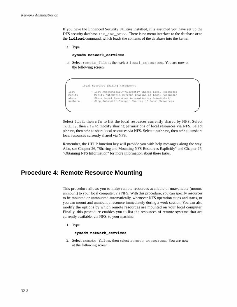
Network Administration
32-2
If you have the Enhanced Security Utilities installed, it is assumed you have set up theDFS security database lid_and_priv. There is no menu interface to the database or tothe lidload command, which loads the contents of the database into the kernel.
a. Type
sysadm network_services
b. Select remote_files ; then select local_resources . You are now atthe following screen:
Select list , then nfs to list the local resources currently shared by NFS. Selectmodify , then nfs to modify sharing permissions of local resources via NFS. Selectshare , then nfs to share local resources via NFS. Select unshare , then nfs to unsharelocal resources currently shared via NFS.
Remember, the HELP function key will provide you with help messages along the way.Also, see Chapter 26, "Sharing and Mounting NFS Resources Explicitly" and Chapter 27,"Obtaining NFS Information" for more information about these tasks.
Procedure 4: Remote Resource Mounting 32
This procedure allows you to make remote resources available or unavailable (mount/unmount) to your local computer, via NFS. With this procedure, you can specify resourcesto be mounted or unmounted automatically, whenever NFS operation stops and starts, oryou can mount and unmount a resource immediately during a work session. You can alsomodify the options by which remote resources are mounted on your local computer.Finally, this procedure enables you to list the resources of remote systems that arecurrently available, via NFS, to your machine.
1. Type
sysadm network_services
2. Select remote_files , then select remote_resources . You are nowat the following screen:
Local Resource Sharing Management
list - List Automatically-Currently Shared Local Resourcesmodify - Modify Automatic-Current Sharing of Local Resourcesshare - Share Local Resources Automatically-Immediatelyunshare - Stop Automatic-Current Sharing of Local Resources
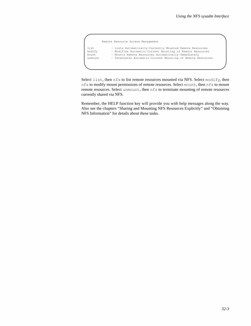
Using the NFS sysadm Interface
32-3
Select list , then nfs to list remote resources mounted via NFS. Select modify , thennfs to modify mount permissions of remote resources. Select mount , then nfs to mountremote resources. Select unmount , then nfs to terminate mounting of remote resourcescurrently shared via NFS.
Remember, the HELP function key will provide you with help messages along the way.Also see the chapters “Sharing and Mounting NFS Resources Explicitly” and “ObtainingNFS Information” for details about these tasks.
Remote Resource Access Management
list - Lists Automatically-Currently Mounted Remote Resourcesmodify - Modifies Automatic-Current Mounting of Remote Resourcesmount - Mounts Remote Resources Automatically-Immediatelyunmount - Terminates Automatic-Current Mounting of Remote Resources

Network Administration
32-4

-5
6Part 6Remote Procedure Call Administration
Replace with Part 6 tab

Network Administration
-6

33Remote Procedure Call (RPC) Administration
Introduction to RPC Administration . . . . . . . . . . . . . . . . . . . . . . . . . . . . . . . . . . . . . 33-1RPC in the Enhanced Security Environment . . . . . . . . . . . . . . . . . . . . . . . . . . . 33-1
Becoming the RPC Administrator. . . . . . . . . . . . . . . . . . . . . . . . . . . . . . . . 33-1The tfadmin Command . . . . . . . . . . . . . . . . . . . . . . . . . . . . . . . . . . . . . . . . 33-2
RPC Administration Files . . . . . . . . . . . . . . . . . . . . . . . . . . . . . . . . . . . . . . . . . . . . . 33-2RPC and Name-to-Address Mapping. . . . . . . . . . . . . . . . . . . . . . . . . . . . . . . . . 33-2System RC File /etc/rc2.d/S75rpc . . . . . . . . . . . . . . . . . . . . . . . . . . . . . . . . . . . 33-2The /etc/publickey File . . . . . . . . . . . . . . . . . . . . . . . . . . . . . . . . . . . . . . . . . . . . 33-3The SRPC_DOMAIN Variable . . . . . . . . . . . . . . . . . . . . . . . . . . . . . . . . . . . . . 33-3
Secure RPC Overview . . . . . . . . . . . . . . . . . . . . . . . . . . . . . . . . . . . . . . . . . . . . . . . . 33-4RPC Domains . . . . . . . . . . . . . . . . . . . . . . . . . . . . . . . . . . . . . . . . . . . . . . . . . . . 33-5
Secure RPC Administration. . . . . . . . . . . . . . . . . . . . . . . . . . . . . . . . . . . . . . . . . . . . 33-5Establishing Secure RPC Domains . . . . . . . . . . . . . . . . . . . . . . . . . . . . . . . . . . 33-6Master /etc/publickey File . . . . . . . . . . . . . . . . . . . . . . . . . . . . . . . . . . . . . . . . . 33-6
Adding RPC Users with the newkey Command . . . . . . . . . . . . . . . . . . . . . 33-7Network Passwords and the chkey Command . . . . . . . . . . . . . . . . . . . . . . 33-8
Troubleshooting Note . . . . . . . . . . . . . . . . . . . . . . . . . . . . . . . . . . . . . . . . . . . . . 33-8

Network Administration
33-1
33i
Chapter 33Remote Procedure Call (RPC) Administration
333333
Introduction to RPC Administration 33
Remote Procedure Call (RPC) administration consists of configuring administration filesthat:
• Establish name-to-address mapping relationships
• Start server daemons at boot time
• Prompt users for a network password at login (secure RPC)
• Edit a master machine /etc/publickey file that determines who canaccess secure RPC services (secure RPC)
• Start ypdaemons
Servers are started at boot time by editable system RC scripts. The file /etc/profile isedited to call keylogin to query for a network password at login time.
NIS is currently the recommended default mechanism for administering secure RPC (seeChapter 34, "Network Information Service Administration" for more information).
RPC in the Enhanced Security Environment 33
RPC administration will be different if you are running the Enhanced Security Utilities.This section describes what you, as RPC administrator, must do to execute RPCadministrative commands on a secure system.
Becoming the RPC Administrator 33
Because of the Least Privileged Mechanism (LPM) of the Enhanced Security Utilities, theconcept of the superuser has been replaced by administrative roles. Each administrativerole is associated with commands and privileges to administer certain aspects of thesystem. To administer RPC, you must assume the role of the network administrator, NET.
The NET role is predefined on your system, but before you can log in as RPCadministrator, the system administrator must create the login root and assign it the NETrole. This is done using the adminuser command.
Network Administration
33-2
Any time you want to administer RPC, you must log in as the root ID with theappropriate NET privileges. For information about assigning roles, see “Basic Security” inSystem Administration, or the adminuser(1M) manual page.
The tfadmin Command 33
To perform RPC administrative functions on an LPM system, you must precede eachadministrative command that requires special privileges with the tfadmin command.tfadmin checks the Trusted Facility Management (TFM) databases for the appropriateprivileges associated with the NET role or other TFM roles to which you may belong. Ifthe privileges are not associated with the command, tfadmin aborts the command.
For example, if you are administering a non-LPM system and you want to assign amachine to a domain, type
domainname name
On an LPM system, you would type
tfadmin domainname name
tfadmin is needed only for administrative commands in the TFM database.
NOTE
The examples used in this chapter assume the user is executingRPC commands on a non-LPM system, unless specified other-wise.
RPC Administration Files 33
RPC and Name-to-Address Mapping 33
Name-to-address mapping must be in effect for RPC (secure or otherwise) to work. Referto Chapter 3, "Administering Name-to-Address Mapping" for name-to-address mappingadministrative procedures.
System RC File /etc/rc2.d/S75rpc 33
RPC servers can be started at system boot time. When the system comes up in init state 2,all of the scripts in /etc/rc2.d are executed. One of these scripts, /etc/rc2.d/S75rpc, starts the RPC servers.
The system administrator can edit the script to start additional servers.
Remote Procedure Call (RPC) Administration
33-3
NOTE
The server keyserv must also be running for secure RPC towork properly. Administrators may wish to edit the /etc/rc2.d/S75rpc script and remove the comment character (#)for the keyserv lines so that keyserv will start at boot time. Ifnot, keyserv will have to be started manually.
The /etc/publickey File 33
Secure RPC information is kept in this file, which is controlled by a domain master server.For each secure RPC user known to a master, this file contains:
• operating system name
• user ID
• RPC domain name
• public key
• secret key
The triple (operating system, user ID, domain) forms a unique key into this database ofpublic/secret key pairs that are required by the RPC built-in security protocol.
NOTE
The user ID field in /etc/publickey may also be a host name.This allows more than one root user per domain.
The SRPC_DOMAIN Variable 33
All machines supporting secure RPC must have what is known as a secure RPC domainname. By default, a machine's secure RPC domain name is null and (because it is null),secure RPC will not work on the machine.
A domain name can be set using the domainname(1M) command, but it will not beremembered across reboots. For preservation of the name across reboots, administratorsneed to edit their /etc/conf/pack.d/name/space.c file to set the SRPC_DOMAINtunable to their desired secure RPC domain name. For example, to change a machine'sdomain name from null to finance, the system administrator would find the line:
#define SRPC_DOMAIN=""
in /etc/conf/pack.d/name/space.c and change it to
#define SRPC_DOMAIN="finance"
Network Administration
33-4
After this is done, the kernel must be rebuilt and the system rebooted for the change totake effect. To rebuild the kernel and reboot your system, type:
/etc/conf/bin/idbuild -B cd /; shutdown -y -g0 -i6
The above steps will rebuild the kernel, and reboot your system immediately. For moreinformation on the idbuild command, see idbuild(1M). For more information onthe shutdown command, see shutdown(1M) .
Secure RPC Overview 33
There is a security protocol, based on DES encryption, built into the RPC package.Remote programs that use secure RPC expect client users to have a public/secret key entryin a shared master /etc/publickey file. Access to secure RPC programs is controlledby the keyserv daemon which accesses the /etc/publickey file when users invokekeylogin. One /etc/publickey database exists for each secure RPC domain.
Secure RPC users must be given entries in /etc/publickey by the RPC administratorbefore they can use secure RPC programs.
In addition, the administrator of every client machine should edit /etc/profile toremove the comment character that has commented out the keylogin command; in thisway, keylogin will be invoked for each user at login time. Thereafter secure RPCcommands and programs can be used in the same way ordinary commands and programsare used.
NOTE
Every machine that allows use of secure RPC is a client machine.
One of the secure RPC commands, chkey, allows users to change their secure RPC pass-words.
The .profile files of secure RPC users should be set up to call keylogout(1)automatically at the end of a terminal session. For example:
# .profile code fragmenttrap "keylogout" 0
CAUTION
A secure RPC user should always execute keylogout beforelogging off the system. Failure to do so is a serious securityinfraction.
Remote Procedure Call (RPC) Administration
33-5
[See sh(1) for details on use of trap for executing commands at the end of a terminalsession.]
NOTE
The presence of secure RPC has no effect on remote programsthat do not use the secure protocol. Such programs work normally,whether or not the user is also a secure RPC user.
RPC Domains 33
All machines using secure RPC must have a secure RPC domain name. One machine perdomain acts as master server for the domain. The domainname(1M) command is usedto set a machine's domain name. The machine's SRPC_DOMAIN tunable should also be setto the secure RPC domain name. Otherwise, the name is forgotten across reboots. See“The SRPC_DOMAIN Variable” on page 33-3 for information on setting theSRPC_DOMAIN variable.
Secure RPC identifies users using a triple (operating system, uid, domain). Thus, users mayhave multiple registrations with RPC, provided all such triples are unique. For example, auser may belong to more than one domain, with operating system and uid identical foreach.
Secure RPC Administration 33
In general, administering secure RPC is accomplished as follows:
1. A domain name is chosen (for multiple domains, more than one domainname is chosen). Secure RPC domain names are set on participatingmachines , us ing the domainname(1M) command, and theSRPC_DOMAIN tunable is set to the secure RPC domain name. See “TheSRPC_DOMAIN Variable” on page 33-3.
2. For each user or host to be allowed access to secure RPC services, domainmaster machine administrators add entries to their master /etc/publickey file.
3. keyserv and NIS daemons are started.
4. Administrators start keyserv , either manually or by means of a boot-timescript.
5. The system administrators of client machines remove the commentcharacter that has commented out the keylogin command from theirmachine's /etc/profile and they direct their secure RPC users to add atrap to their $HOME/.profile so that keylogout will be called whentheir sessions end.
Network Administration
33-6
The following sections detail this procedure.
NOTE
When slave servers are in use, master servers may have clients aswell as slaves.
Establishing Secure RPC Domains 33
For many networked systems, a single secure RPC domain will suffice. Administrators arenotified of the domain name, and they use the domainname(1M) command to establishthat name as the secure RPC domain name for their machine. For example, to set the amachine's domain name to research :
# domainname research
For networked systems having multiple domains, the process is the same, except that twoor more different domains will be in use in the network.
Administrators should also set their machine's SRPC_DOMAIN tunable to their secureRPC domain name, as described in “The SRPC_DOMAIN Variable” on page 33-3. If thisis not done, the domain name will be forgotten across reboots.
A machine can be part of only one domain at any given time. The decision to use single ormultiple domains depends on need. In general, the advantages of multiple domainsinclude:
• Duplicate operating system/user ID pairs can be using secure RPC(provided they are in different domains).
• Access to secure RPC programs can be made selective, if some programsare not available to all domains.
The primary advantage of using a single domain is simplified administration.
Master /etc/publickey File 33
The /etc/publickey file is a database of public/secret key pairs. The file containspairs for users and hosts authorized to use secure RPC. Remote procedures that use theDES authentication protocol (built into the RPC package) expect to find public/secret keypairs (for the processes that call them) in /etc/publickey. A system administratormust therefore add an entry to /etc/publickey for each user/host to be granted accessto secure RPC resources. A single /etc/publickey file (on a master server or on acollection of master and slave servers) is used and shared over the network by machineshaving access to the file.
Remote Procedure Call (RPC) Administration
33-7
NOTE
Secure RPC programs are not required to be hosted by the samemachine that hosts the master /etc/publickey file. Themaster /etc/publickey machine is not necessarily the serverfor any of the secure RPC application programs or commands.
Adding RPC Users with the newkey Command 33
On the domain master server machine (only), the system administrator grants a user orhost access to secure RPC in that domain by adding an entry to the /etc/publickeyfile. This is accomplished using the newkey(1M) command.
NOTE
The newkey command must be executed on the master servermachine by the RPC administrator. Furthermore, prior to usingnewkey, the machine's secure RPC domain name must havebeen set.
For example, to add an entry for the user alice the system administrator would enter thefollowing on the master server:
The -u option signifies that alice is a user ID. The domain field for this entry is thedomain of the master server on which this command is executed. This is the only way thatuser alice can get access to this particular secure RPC domain.
The newkey command can also be used with the -h option to give access to hosts, that is,to root users on hosts on the network:
Within the domain of secure RPC users having entries in a master /etc/publickeyfile, all user names and IDs must be unique. The -h option is provided to allow more thanone root user to have access to secure RPC. Because root users on different machineshave the same name and ID, it would be impossible for more than one of them to be a
master# newkey -u alicepassword: passwordRe-enter new passwd: password
master# newkey -h clientpassword: passwordRe-enter new passwd: password
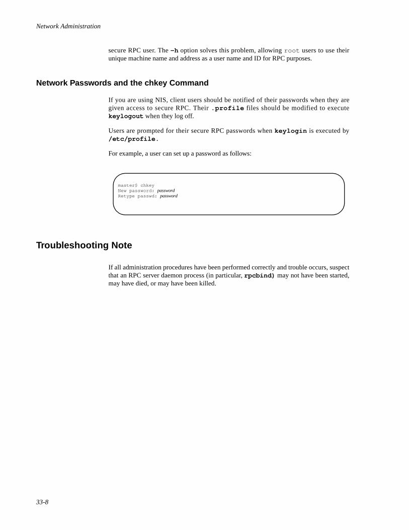
Network Administration
33-8
secure RPC user. The -h option solves this problem, allowing root users to use theirunique machine name and address as a user name and ID for RPC purposes.
Network Passwords and the chkey Command 33
If you are using NIS, client users should be notified of their passwords when they aregiven access to secure RPC. Their .profile files should be modified to executekeylogout when they log off.
Users are prompted for their secure RPC passwords when keylogin is executed by/etc/profile.
For example, a user can set up a password as follows:
Troubleshooting Note 33
If all administration procedures have been performed correctly and trouble occurs, suspectthat an RPC server daemon process (in particular, rpcbind) may not have been started,may have died, or may have been killed.
master$ chkeyNew password: passwordRetype passwd: password

-9
7Part 7Network Information Service Administration
Replace with Part 7 tab

Network Administration
-10
34Network Information Service Administration
Introduction to NIS Administration. . . . . . . . . . . . . . . . . . . . . . . . . . . . . . . . . . . . . . 34-1What Is NIS? . . . . . . . . . . . . . . . . . . . . . . . . . . . . . . . . . . . . . . . . . . . . . . . . . . . 34-1The NIS Elements. . . . . . . . . . . . . . . . . . . . . . . . . . . . . . . . . . . . . . . . . . . . . . . . 34-2NIS in the Enhanced Security Environment. . . . . . . . . . . . . . . . . . . . . . . . . . . . 34-2
Becoming the NIS Administrator . . . . . . . . . . . . . . . . . . . . . . . . . . . . . . . . 34-2The tfadmin Command . . . . . . . . . . . . . . . . . . . . . . . . . . . . . . . . . . . . . . . . 34-3The ypbuild Command . . . . . . . . . . . . . . . . . . . . . . . . . . . . . . . . . . . . . . . . 34-3
The NIS Environment. . . . . . . . . . . . . . . . . . . . . . . . . . . . . . . . . . . . . . . . . . . . . 34-3The NIS Domain . . . . . . . . . . . . . . . . . . . . . . . . . . . . . . . . . . . . . . . . . . . . . 34-4NIS Machine Types . . . . . . . . . . . . . . . . . . . . . . . . . . . . . . . . . . . . . . . . . . . 34-4
NIS Servers . . . . . . . . . . . . . . . . . . . . . . . . . . . . . . . . . . . . . . . . . . . . . 34-4NIS Clients. . . . . . . . . . . . . . . . . . . . . . . . . . . . . . . . . . . . . . . . . . . . . . 34-5NIS Binding . . . . . . . . . . . . . . . . . . . . . . . . . . . . . . . . . . . . . . . . . . . . . 34-5
Files Managed by NIS. . . . . . . . . . . . . . . . . . . . . . . . . . . . . . . . . . . . . . . . . 34-6NIS Maps. . . . . . . . . . . . . . . . . . . . . . . . . . . . . . . . . . . . . . . . . . . . . . . . . . . 34-7
Implementing the NIS . . . . . . . . . . . . . . . . . . . . . . . . . . . . . . . . . . . . . . . . . . . . . . . . 34-7Establishing the NIS Domain . . . . . . . . . . . . . . . . . . . . . . . . . . . . . . . . . . . . . . . 34-7Preparing the Maps. . . . . . . . . . . . . . . . . . . . . . . . . . . . . . . . . . . . . . . . . . . . . . . 34-9Making the Maps . . . . . . . . . . . . . . . . . . . . . . . . . . . . . . . . . . . . . . . . . . . . . . . . 34-9Choosing NIS Servers . . . . . . . . . . . . . . . . . . . . . . . . . . . . . . . . . . . . . . . . . . . . 34-9Setting the Master Server . . . . . . . . . . . . . . . . . . . . . . . . . . . . . . . . . . . . . . . . . . 34-9Setting Slave Servers . . . . . . . . . . . . . . . . . . . . . . . . . . . . . . . . . . . . . . . . . . . . . 34-10Setting up an NIS Client. . . . . . . . . . . . . . . . . . . . . . . . . . . . . . . . . . . . . . . . . . . 34-11NIS Masters as Clients . . . . . . . . . . . . . . . . . . . . . . . . . . . . . . . . . . . . . . . . . . . . 34-11Terminating NIS . . . . . . . . . . . . . . . . . . . . . . . . . . . . . . . . . . . . . . . . . . . . . . . . . 34-12
Relationship of NIS Maps to Local Files . . . . . . . . . . . . . . . . . . . . . . . . . . . . . . . . . 34-12Default NIS Maps. . . . . . . . . . . . . . . . . . . . . . . . . . . . . . . . . . . . . . . . . . . . . . . . 34-12Integration of Maps with Local files . . . . . . . . . . . . . . . . . . . . . . . . . . . . . . . . . 34-13Replaced Local Files . . . . . . . . . . . . . . . . . . . . . . . . . . . . . . . . . . . . . . . . . . . . . 34-14Appended Local Files. . . . . . . . . . . . . . . . . . . . . . . . . . . . . . . . . . . . . . . . . . . . . 34-14
Password File . . . . . . . . . . . . . . . . . . . . . . . . . . . . . . . . . . . . . . . . . . . . . . . 34-14Group File . . . . . . . . . . . . . . . . . . . . . . . . . . . . . . . . . . . . . . . . . . . . . . . . . . 34-15Mail and Sendmail Aliases File . . . . . . . . . . . . . . . . . . . . . . . . . . . . . . . . . 34-15
Administering NIS Maps. . . . . . . . . . . . . . . . . . . . . . . . . . . . . . . . . . . . . . . . . . . . . . 34-15Updating Existing Maps. . . . . . . . . . . . . . . . . . . . . . . . . . . . . . . . . . . . . . . . . . . 34-16
Modifying Standard Maps. . . . . . . . . . . . . . . . . . . . . . . . . . . . . . . . . . . . . . 34-16Creating and Modifying Non-Standard Maps. . . . . . . . . . . . . . . . . . . . . . . 34-16
Updating Maps Built from Existing ASCII Files. . . . . . . . . . . . . . . . . 34-17Updating Maps Built from Standard Input . . . . . . . . . . . . . . . . . . . . . 34-17
Propagating an NIS Map . . . . . . . . . . . . . . . . . . . . . . . . . . . . . . . . . . . . . . . . . . 34-18Using crontab with ypxfr. . . . . . . . . . . . . . . . . . . . . . . . . . . . . . . . . . . . . . . 34-19Using Shell Scripts with ypxfr . . . . . . . . . . . . . . . . . . . . . . . . . . . . . . . . . . 34-19Directly Invoking ypxfr . . . . . . . . . . . . . . . . . . . . . . . . . . . . . . . . . . . . . . . . 34-20Logging ypxfr's Activities. . . . . . . . . . . . . . . . . . . . . . . . . . . . . . . . . . . . . . 34-20
Password File Updates . . . . . . . . . . . . . . . . . . . . . . . . . . . . . . . . . . . . . . . . . . . . 34-20Adding New NIS Maps to the Makefile . . . . . . . . . . . . . . . . . . . . . . . . . . . . . . . 34-21
Adding a New NIS Server to the Original Set. . . . . . . . . . . . . . . . . . . . . . . . . . . . . . 34-21

Network Administration
Changing a Map's Master Server . . . . . . . . . . . . . . . . . . . . . . . . . . . . . . . . . . . . 34-22Summary of NIS-Related Commands . . . . . . . . . . . . . . . . . . . . . . . . . . . . . . . . . . . . 34-23Fixing NIS Problems . . . . . . . . . . . . . . . . . . . . . . . . . . . . . . . . . . . . . . . . . . . . . . . . . 34-25
Debugging an NIS Client . . . . . . . . . . . . . . . . . . . . . . . . . . . . . . . . . . . . . . . . . . 34-25Hanging Commands on the Client. . . . . . . . . . . . . . . . . . . . . . . . . . . . . . . . 34-25NIS Is Unavailable. . . . . . . . . . . . . . . . . . . . . . . . . . . . . . . . . . . . . . . . . . . . 34-26ypbind Crashes . . . . . . . . . . . . . . . . . . . . . . . . . . . . . . . . . . . . . . . . . . . . . . 34-27ypwhich Displays Are Inconsistent . . . . . . . . . . . . . . . . . . . . . . . . . . . . . . . 34-28
Debugging an NIS Server . . . . . . . . . . . . . . . . . . . . . . . . . . . . . . . . . . . . . . . . . . 34-28Servers Have Different Versions of an NIS Map. . . . . . . . . . . . . . . . . . . . . 34-28ypserv Crashes. . . . . . . . . . . . . . . . . . . . . . . . . . . . . . . . . . . . . . . . . . . . . . . 34-29
Turning off NIS . . . . . . . . . . . . . . . . . . . . . . . . . . . . . . . . . . . . . . . . . . . . . . . . . . . . . 34-30
34-1
34Chapter 34Network Information Service Administration
343434
Introduction to NIS Administration 34
This chapter explains how to administer the Network Information Service (NIS)—adistributed network lookup service formerly known as Yellow Pages.
Information in the chapter includes:
• The NIS environment
• Setting up NIS servers
• Setting up an NIS client
• Creating and updating maps
• NIS-related commands
• Fixing NIS problems
What Is NIS? 34
The Network Information System (NIS) is a distributed name service that replaces copiesof commonly replicated configuration files with a centralized management facility. Insteadof having to manage each host's files (like /etc/hosts , /etc/passwd , etc.), it is onlynecessary to maintain one version of the file on the central server. Hosts that are using NISretrieve information as needed from a server system. Changes to an NIS-managedconfiguration file will be automatically propagated to clients systems on the same network
NIS is best suited for files that have no host-specific information in them and hence aregenerally the same on all hosts in a network. Examples would be the files /etc/groupand /etc/services . Some files, like the services files, are ignored entirely once NIS isrunning. NIS provides all information to hosts from its centralized database. For otherfiles, like /etc/group , the local file is augmented by information from the centralizeddatabase
NIS may also be used for any general data file that is accessed on one or more key fields.Site-specific database files may also be managed by NIS.
Network Administration
34-2
The NIS Elements 34
The NIS service is composed of the following elements:
• domains
• maps
• daemons:
- ypserv -server process [see ypserv(1M) ]
- ypbind -binding process [for ypbind , see ypserv(1M)]
- ypupdated - server for changing map entries [seeypupdated(1M)]
- yppasswdd - server for changing /etc/passwd entries [seeyppasswdd(1M)]
• utilities:
- ypcat - lists data in a map [see ypcat(1)]
- ypwhich - lists name of NIS server [see ypwhich(1)]
- ypmatch - finds a key in a map [see ypmatch(1)]
- ypinit - builds and installs an NIS database, or initializes a clientAlso used to terminate and tear-down NIS. [see ypinit(1M)]
- yppoll - gets protocol version from server [see yppoll(1M)]
- yppush - propagates data from master to slave NIS server [seeyppush(1M)]
- ypset - sets binding to a particular server [see ypset(1M)]
- ypxfr - transfers data from master to slave NIS server [seeypxfr(1M)]
- makedbm — creates dbm file for an NIS map [seemakedbm(1M)]
NIS in the Enhanced Security Environment 34
NIS administration will be different if you are running the Enhanced Security Utilities.This section describes what you, as NIS administrator, must do to execute NISadministrative commands on a secure system.
Becoming the NIS Administrator 34
Because of the Least Privileged Mechanism (LPM) of the Enhanced Security Utilities, theconcept of the NIS administrator has been replaced by administrative roles. Eachadministrative role is associated with commands and privileges to administer certain
Network Information Service Administration
34-3
aspects of the system. To administer NIS, you must assume the role of the networkadministrator, NET.
The NET role is predefined on your system, but before you can log in as NIS administrator,the system administrator must create the login root and assign it the NET role. This isdone using the adminuser command.
Any time you want to administer NIS, you must log in as the root ID with theappropriate NET privileges. For information about assigning roles, see “Basic Security” inSystem Administration, or the adminuser(1M) manual page.
The tfadmin Command 34
To perform NIS administrative functions on an LPM system, you must precede eachadministrative command with the tfadmin command. Before executing a command,tfadmin checks the Trusted Facility Management (TFM) databases for the appropriateprivileges associated with the NET role or other TFM roles to which you belong. If theprivileges are not associated with the command, tfadmin aborts the command.
For example, if you are administering a non-LPM system and you want to assign amachine to a domain, type
domainname name
On an LPM system, you would type
tfadmin domainname name
Note that tfadmin is only needed for administrative commands in the TFM database.
The ypbuild Command 34
Use the /var/yp/ypbuild command only on systems running the Enhanced SecurityUtilities. /var/yp/ypbuild replaces the make(1) program for converting the NISmaps from ASCII to non-ASCII format. Enter ypbuild on the command line with its fullpathname and the type of shell to be invoked as shown in the following example.
/var/yp/ypbuild SHELL=/sbin/sh
NOTE
The examples used in this chapter assume the user is executingNIS commands on a non-LPM system, unless specified otherwise.
The NIS Environment 34
NIS service is based on information contained in NIS maps. Maps are non-ASCIIadministrative files, which usually derive from ASCII files traditionally found in the /etcdirectory. Each NIS map has a mapname used by programs to access it. On a network
Network Administration
34-4
running NIS, at least one NIS server per domain maintains a set of NIS maps for otherhosts in the domain to query.
The service is mediated by the daemons ypserv and ypbind, and updates arefacilitated by the daemons ypupdated and yppasswdd .
The NIS Domain 34
An NIS domain is an arbitrary name that designates which machines will make use of acommon set of maps. Maps for each domain are located in separate directories,/var/yp/ domainname, on the NIS server (see “NIS Servers” on page 34-4). Forexample, the maps for machines that belong to the domain accounting will be locatedin the directory /var/yp/accounting on their corresponding NIS server.
No restrictions are placed on whether a machine can belong to a given domain.Assignment to a domain is done at the local level of each machine by the systemadministrator logged in as the NIS administrator. See “Establishing the NIS Domain” onpage 34-7 for instructions on how to establish the NIS domain.
NIS Machine Types 34
There are three types of NIS machines:
• master server
• slave server
• client
Any machine can be an NIS client. Servers are generally also clients.
NIS Servers 34
Servers are divided into master and slave servers. The master server contains the masterset of maps that are updated as necessary. Slave servers have copies of the master's set ofNIS maps, but cannot modify NIS maps directly. The master server is responsible for allmap maintenance and distribution to slave servers.
Either type of server may handle client requests. If you have only one NIS server on thenetwork, it should be designated the master server. Otherwise, the master server should bethe system that can best propagate NIS updates with the least performance degradation.
Slave servers allow the system administrator to distribute evenly the load required inanswering NIS requests from client systems. A stylized representation of the relationshipbetween master, slaves and clients is shown in Figure 34-1.
A server may be a master in regard to one map, and a slave in regard to another. However,randomly assigning maps to NIS servers can cause a great deal of administrativeconfusion. You are strongly urged to make a single server the master for all the maps youcreate within a single domain. The examples in this chapter assume that one server is themaster for all maps in the domain.
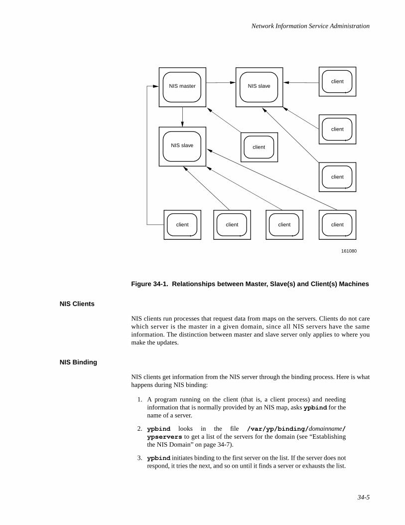
Network Information Service Administration
34-5
Figure 34-1. Relationships between Master, Slave(s) and Client(s) Machines
NIS Clients 34
NIS clients run processes that request data from maps on the servers. Clients do not carewhich server is the master in a given domain, since all NIS servers have the sameinformation. The distinction between master and slave server only applies to where youmake the updates.
NIS Binding 34
NIS clients get information from the NIS server through the binding process. Here is whathappens during NIS binding:
1. A program running on the client (that is, a client process) and needinginformation that is normally provided by an NIS map, asks ypbind for thename of a server.
2. ypbind looks in the file /var/yp/binding/ domainname/ypservers to get a list of the servers for the domain (see “Establishingthe NIS Domain” on page 34-7).
3. ypbind initiates binding to the first server on the list. If the server does notrespond, it tries the next, and so on until it finds a server or exhausts the list.
NIS master
161080
NIS slave
NIS slave
client client
client
client client
client
client
client
Network Administration
34-6
4. ypbind tells the client process which server to talk to. The client then for-wards the request directly to the server.
5. The ypserv daemon on the NIS server handles the request by consultingthe appropriate map.
6. ypserv then sends the requested information back to the client.
The binding between a client and a server can change with the network's load as theservice tries to compensate for current activity; that is, a client may get information fromone server at one time and from another server at a different time.
To find out which NIS server is currently providing service to a client, use the ypwhichcommand
ypwhich hostname
where hostname is the name of the client. If no hostname is mentioned, ypwhich defaultsto the local host (the machine on which the command is entered).
Files Managed by NIS 34
By default, the following system administrative files will be managed by NIS.
Once NIS is running, it will replace or supplement all of these files. The systemadministrator may choose to not have one or more of these files managed by NIS. Or, theadministrator may want to add additional files to this set. The procedure for doing this isdescribed in “Administering NIS Maps”.
File Contains
/etc/passwd User names, user IDs and password information.
/etc/group User groups and group IDs.
/etc/hosts Hostnames and IP addresses.
/etc/networks Network addresses.
/etc/rpc Remote procedure call program numbers.
/etc/services Network port numbers and services names.
/etc/protocols Network protocol names and numbers.
/etc/ethers Ethernet numbers.
/etc/publickey Public and private keys used for secure RPC.
/etc/netgroup Netgroup definitions (used by NIS).
/etc/netmasks Network masks.
/etc/mail/names Mail alias names.
/etc/ucbmail/alias Sendmail alias names.
Network Information Service Administration
34-7
NIS Maps 34
NIS itself, does not use the above files directly. Instead it will use “maps”. Information inNIS maps is organized in dbm(3) format. Input to makedbm(1M) must be in the formof key/value pairs where key is the first word of each line and value is whatever follows inthat line. The pairs of keys and values are preserved in the NIS maps so that programs canuse the keys to look up the values.
Sometimes an NIS managed file will have more than one map. Each map will use adifferent key that can be used to locate key/value pairs. For example, there are two mapsassociated with the /etc/passwd file
passwd.byname : looks up data in the passwd database based on username.
passwd.byuid : looks up data in the passwd database based on user ID.
The most commonly used maps will often have “nicknames” which correspond directly tothe name of the original file: for example, the nickname for passwd.byname is simplypasswd.
Implementing the NIS 34
Implementation of the NIS service consists of the following steps:
1. Establishing the domain(s) for your machines.
2. Writing or preparing the maps in ASCII form.
3. Making the maps
4. Choosing NIS servers
5. Setting the master server
6. Setting slave servers
7. Starting up an NIS client
8. NIS masters as clients
9. Terminating NIS
10. Starting daemons in the slave server(s)
11. Initializing the clients
The following sections describe each of these steps.
Establishing the NIS Domain 34
Before you configure machines as NIS servers or clients, you must prepare the NISdomain by:
Network Administration
34-8
• Giving it a name.
A domain name can be up to 256 characters long. The name of the databasedirectory /var/yp/ domainname will correspond to the shortened alias for thedomain name.
• Designating which machines will serve or be served by the NIS domain.
Once you have chosen a domain name, make a list of network hosts that will give orreceive NIS service within that domain.
• Determining which machine should be master server (you can alwayschange this at a later date).
• Listing which hosts on the network, if any, are to be slave servers.
• Finally, listing all the hosts that are to be NIS clients.
You will probably want all hosts in your network's administrative domain to receive NISservices, although this is not strictly necessary. If this is the case, give the NIS domain thesame name as the network administrative domain.
There are several methods used to establish the domain
1. By using the domainname(1M) command directly such as:
domainname 'name'
This method is only temporary.
A better way would be to modify the domain definition in the system start-up script /etc/rc2.d/S80nis . This script invokes the utilitydomainname(1M) with the indicated domain specified.
2. By use of the shell script ypinit(1M). ypinit(1M) is highlyrecommended as the mechanism used to initialize NIS masters, slaves andclients.
ypinit(1M) will prompt for the name of the domain. With thisinformation it will do -both- steps listed in #1 (i.e. call domainname(1M)and modify /etc/rc2.d/S80nis ).
3. By modifying the file /etc/conf/pack.d/name/space.c andassigning a name to SRPC_DOMAIN as follows:
#define SRPC_DOMAIN'name’
where name is the name of the domain.
After this is done, the kernel must be rebuilt and rebooted for the change totake effect.
Network Information Service Administration
34-9
Preparing the Maps 34
As released, all files listed in the table in “Files Managed by NIS” will be built into NISmaps. As a site administrator, it may be desirable to not have some of these files handledby NIS or to add additional ones. This can be done by editing the file /var/yp/Makefile as needed. More on customizing NIS maps wil l be provided in“Administering NIS Maps”.
Making the Maps 34
It is necessary to convert the ASCII versions of the NIS managed files into the nonASCIIfiles in dbm format that the NIS service expects. The prescribed method to do this is to usethe make program using /var/yp/Makefile .
Initially, this step is not required as the shell script ypinit will do this automatically. ypinitwill be described in the following sections.
Choosing NIS Servers 34
It is important to decide which systems will be NIS servers. Because client systems getalmost all of its configuration information from NIS, servers must be highly available andefficient in handling requests. An interruption in NIS service affects all NIS clients.
It is also important that slave servers contain the same data in their copies of the NIS mapsas on the master server. NIS contains several mechanisms for making changes to map filesand distributing these changes to servers on a regular basis. Described in more detail laterin “Administering NIS Maps.”
Setting the Master Server 34
The program that helps you establish NIS masters, slave servers and clients, and permitsthe initial mapping of ASCII files and their propagation, is /usr/sbin/ypinit.
You use the shell script ypinit to build a fresh set of NIS maps on the master server inthe following way:
1. Bring the machine that is going to be your master server to single-usermode, or to a mode that is not defined as running the NIS service, and login as NIS administrator.
2. Type
cd /var/yp/usr/sbin/ypinit -m
3. ypinit prompts for a domain name. The name will be set as described in“Establishing the Domain Name”.
Network Administration
34-10
4. ypinit prompts for a list of other hosts that are to become NIS servers.Enter the name of the server you are working on and the names of all otherNIS servers.
5. ypinit will ask if the yppasswdd daemon should be started. When thisdaemon is enabled, users on server and client may update passwdinformation on the master using yppasswd(1) or passwd(1) .
6. ypinit asks whether you want the procedure to die at the first non-fatalerror or to continue despite non-fatal errors.
If you choose the first option, ypinit will exit at the first problem; youcan then fix the problem and restart ypinit .This is recommended if youare running ypinit for the first time.
If successful, ypinit will do the following:
- rebuild the maps. This is done using the make(1) utility with the Make-file in /var/yp . This builds the map versions of the local administrativefiles using the makedbm(1M) utility.
- modify start-up script /etc/rc2.d/S80nis according to the domainname and options as specified. This script is used to invoke the properdaemons when the system is rebooted.
- invoke the start-up script with the command “sh /etc/rc2.d/S80nisstart” . This immediately gets the proper set of NIS daemons running(i.e. so that a reboot isn't required).
- adds the library tcpip_nis.so to /etc/netconfig. This enablesname to address t ranslat ion for hostnames v ia NIS managed/etc/hosts files. Refer to chapter called “Administering Name-to-Address Mapping”.
NOTE
For security reasons, you may want to restrict access to the masterNIS server.
Setting Slave Servers 34
Your network can have one or more NIS slave servers. Before actually running ypinit tocreate the slave servers, you should take several precautions.
Make sure that the network is working properly before you set up a slave NIS server. Inparticular, check that you can use rcp(1) to send files from the master NIS server toNIS slaves. If you cannot, follow the procedures outlined in User's Guide to permit the useof rcp(1).
Now you are ready to create a new slave server.
Network Information Service Administration
34-11
1. Log in to each slave server as NIS administrator and bring the slave serverto a runlevel, preferably single user, that does not imply running the NISservice. ypserv must not be running.
2. Change directory to /var/yp.
3. ypinit will prompt for the domain name. The domain name for eachslave must be the same as the domain name of the NIS master server.
4. Type
/usr/sbin/ypinit -s master
where master is the host name of the existing NIS master server. Ideally,the named host is the master server, but it can be any host with a stable setof NIS maps, such as another slave server.
5. ypinit will prompt you for a list of other servers. Enter the names of theNIS servers in order of preference. ypinit will not run make as it doeson the master server. Instead it will call the program ypxfr , which trans-fers a copy of the master's NIS map set to the slave server.
6. ypinit will also invoke the proper daemons for a slave server with asimilar procedure as discussed for master servers.
Repeat the procedures above for each machine you want configured as an NIS slaveserver.
Setting up an NIS Client 34
The NIS master system must be running to set up clients. To establish a machine as an NISclient, do the following:
1. Edit the client's local files, as you did for the local files in the slave servers,so that processes consulting those files are sent to the NIS maps.
2. Run
/usr/sbin/ypinit -c
to initialize the client.
With the relevant files in /etc abbreviated and ypbind running, the processes on themachine will be clients of the NIS servers.
At this point, you must have configured a NIS server on the network and have given thatserver's name to ypinit. Otherwise, processes on the client hang if no NIS server isavailable while ypbind is running.
NIS Masters as Clients 34
As the site administrator, you must decide whether or not the NIS master server shouldalso be an NIS client.
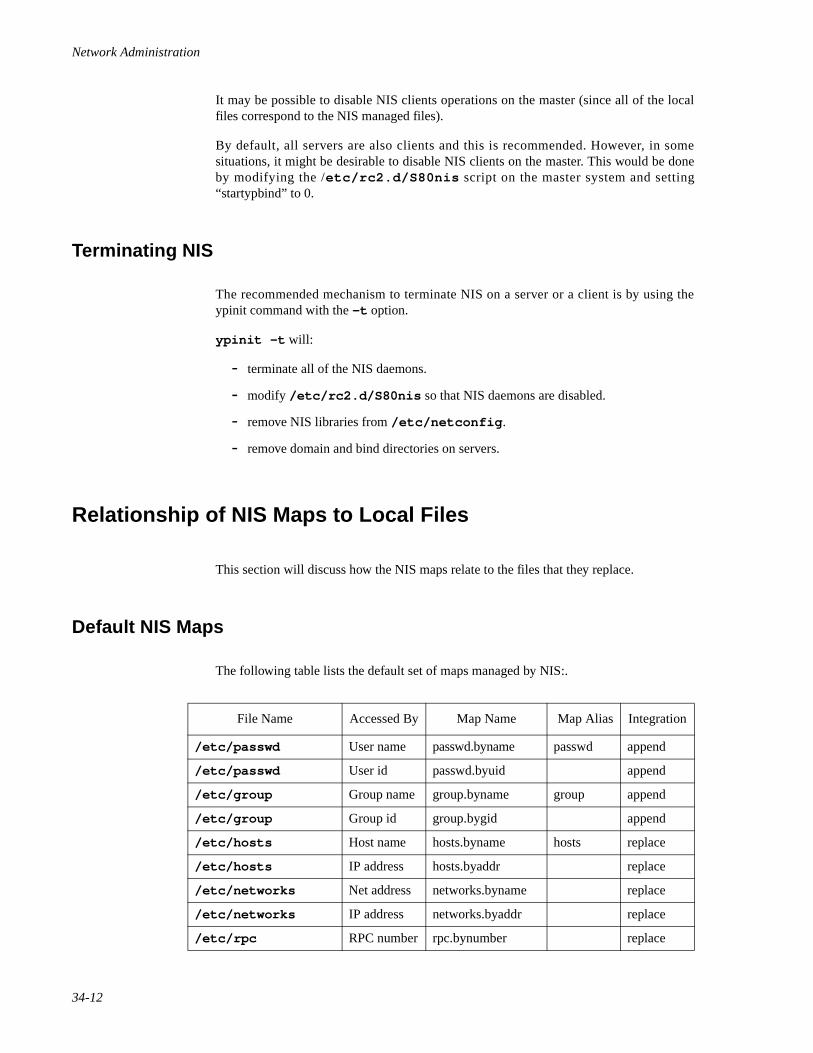
Network Administration
34-12
It may be possible to disable NIS clients operations on the master (since all of the localfiles correspond to the NIS managed files).
By default, all servers are also clients and this is recommended. However, in somesituations, it might be desirable to disable NIS clients on the master. This would be doneby modifying the /etc/rc2.d/S80nis script on the master system and setting“startypbind” to 0.
Terminating NIS 34
The recommended mechanism to terminate NIS on a server or a client is by using theypinit command with the -t option.
ypinit -t will:
- terminate all of the NIS daemons.
- modify /etc/rc2.d/S80nis so that NIS daemons are disabled.
- remove NIS libraries from /etc/netconfig .
- remove domain and bind directories on servers.
Relationship of NIS Maps to Local Files 34
This section will discuss how the NIS maps relate to the files that they replace.
Default NIS Maps 34
The following table lists the default set of maps managed by NIS:.
File Name Accessed By Map Name Map Alias Integration
/etc/passwd User name passwd.byname passwd append
/etc/passwd User id passwd.byuid append
/etc/group Group name group.byname group append
/etc/group Group id group.bygid append
/etc/hosts Host name hosts.byname hosts replace
/etc/hosts IP address hosts.byaddr replace
/etc/networks Net address networks.byname replace
/etc/networks IP address networks.byaddr replace
/etc/rpc RPC number rpc.bynumber replace
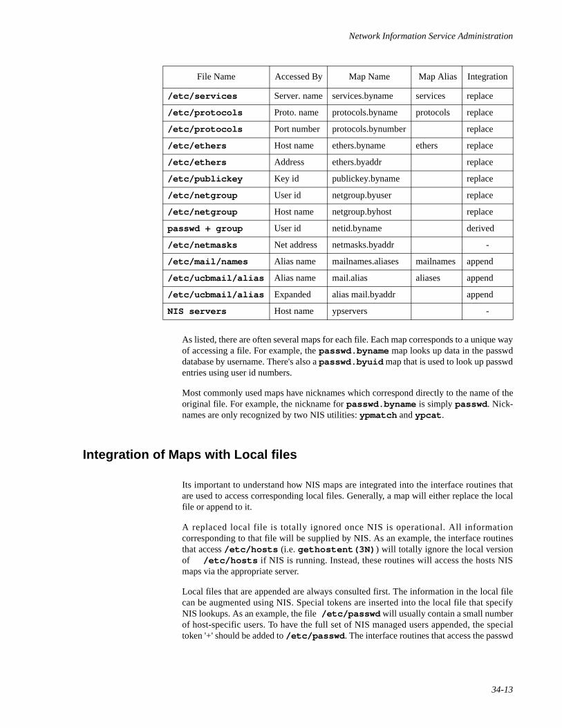
Network Information Service Administration
34-13
As listed, there are often several maps for each file. Each map corresponds to a unique wayof accessing a file. For example, the passwd.byname map looks up data in the passwddatabase by username. There's also a passwd.byuid map that is used to look up passwdentries using user id numbers.
Most commonly used maps have nicknames which correspond directly to the name of theoriginal file. For example, the nickname for passwd.byname is simply passwd . Nick-names are only recognized by two NIS utilities: ypmatch and ypcat .
Integration of Maps with Local files 34
Its important to understand how NIS maps are integrated into the interface routines thatare used to access corresponding local files. Generally, a map will either replace the localfile or append to it.
A replaced local file is totally ignored once NIS is operational. All informationcorresponding to that file will be supplied by NIS. As an example, the interface routinesthat access /etc/hosts (i.e. gethostent(3N) ) will totally ignore the local versionof /etc/hosts if NIS is running. Instead, these routines will access the hosts NISmaps via the appropriate server.
Local files that are appended are always consulted first. The information in the local filecan be augmented using NIS. Special tokens are inserted into the local file that specifyNIS lookups. As an example, the file /etc/passwd will usually contain a small numberof host-specific users. To have the full set of NIS managed users appended, the specialtoken '+' should be added to /etc/passwd . The interface routines that access the passwd
/etc/services Server. name services.byname services replace
/etc/protocols Proto. name protocols.byname protocols replace
/etc/protocols Port number protocols.bynumber replace
/etc/ethers Host name ethers.byname ethers replace
/etc/ethers Address ethers.byaddr replace
/etc/publickey Key id publickey.byname replace
/etc/netgroup User id netgroup.byuser replace
/etc/netgroup Host name netgroup.byhost replace
passwd + group User id netid.byname derived
/etc/netmasks Net address netmasks.byaddr -
/etc/mail/names Alias name mailnames.aliases mailnames append
/etc/ucbmail/alias Alias name mail.alias aliases append
/etc/ucbmail/alias Expanded alias mail.byaddr append
NIS servers Host name ypservers -
File Name Accessed By Map Name Map Alias Integration
Network Administration
34-14
file getpwent(3C) ) will then use both the small number of host-specific users inaddition to the set of NIS users.
Replaced Local Files 34
The following lists the local files that are replaced when NIS is operational. Note that it isnot possible to disable the corresponding interface routines from exclusively using NIS.
/etc/hosts/etc/networks/etc/rpc/etc/services/etc/protocols/etc/ethers/etc/publickey/etc/netgroup
Appended Local Files 34
This section discusses the local files that are appended by NIS.
In general, these files should be stripped to the minimum number of entries needed forbooting, in addition to the host-specific entries.
Password File 34
The following syntax is recognized within the file /etc/passwd :
'+' add entire NIS-managed passwd file.
'+username' add NIS entry for user username.
'+@group' add NIS entries for all users in netgroup group.
'-username' remove NIS entry for user username.
'-@group' remove NIS entries for users in netgroup group.
Note that if /etc/passwd does NOT contain the NIS token '+' then NIS is disabled forpasswd file entries.
Netgroups, as maintained in /etc/netgroup , provides a method for defining a group ofusers (or groups) for administrative purposes. In the /etc/passwd file it can be used toinclude or exclude an entire set of NIS users previously defined as a netgroup.
It will be necessary to have the same number of fields for an NIS entry in the file /etc/passwd as the other entries. Otherwise, the common set of utilities that access the pass-word file may get confused. In addition, it is important that an NIS entry not be consideredvalid when NIS is not running.
Network Information Service Administration
34-15
I t is recommended that the ut i l i t ies useradd(1M) , usermod(1M) anduserdel(1M) be used for adding NIS entries to the passwd file. These utilitiesrecognize NIS syntax and will do proper checking in addition to building correct NISentries for the password file.
Group File 34
The following syntax is recognized within the file /etc/group:
'+' add entire NIS-managed group file.
'+groupname' add NIS entry for group groupname.
'-groupname' remove NIS entry for group groupname.
Note that if /etc/group does NOT contain the NIS token '+' then NIS is disabled forgroup file entries.
As with the passwd file, it is possible to include or exclude an entire set of groups that isdefined as a netgroup (within /etc/netgroup ).
It is recommended that the utilities groupadd(1M) and groupdel(1M) be used foradding NIS entries to the group file. These utilities recognize NIS syntax and will doproper checking in addition to building correct NIS entries for the group file.
Mail and Sendmail Aliases File 34
The aliases files used by mail and sendmail (/etc/mail/names and /etc/ucbmail/alias respectively) can be augmented with NIS managed aliases.
The syntax recognized in these two files is:
'+' add entire NIS-managed name/alias file.
Note that if these files do NOT contain the NIS token '+' then NIS is disabled.
Administering NIS Maps 34
This section describes how to maintain the maps of an existing NIS domain. Subjectsdiscussed include:
• Updating NIS maps
• Propagating an NIS map
• Adding maps to an additional NIS server
• Moving the master map set to a new server
Network Administration
34-16
Updating Existing Maps 34
After you have installed NIS, you will discover that some maps require frequent updatingwhile others never need to change. For example, the hosts map may change frequently ona large company's network. On the other hand, the protocols map probably will changelittle, if at all.
When you need to update a map, you can use one of two updating procedures, dependingon whether the map is standard or non-standard. A standard map is a map in the default setcreated by ypinit from the network databases. Non-standard maps may be any of thefollowing:
• A map included with an application purchased from a vendor
• A map created specifically for your site
• A map existing in a form other than ASCII
The following text explains how to use various updating tools. In practice, you probablywill use them only if you add non-standard maps or change the set of NIS servers after thesystem is up and running.
Modifying Standard Maps 34
Use the following procedure for updating all standard maps:
1. Become NIS administrator on the master server. (Always modify NIS mapson the master server.)
2. Edit the file in /etc that has the same name as the map you want tochange.
3. Type the following:
cd /var/ypmake mapname
The make command will then update your map according to the changesyou made in its corresponding file. It will also propagate it among theservers (see “Propagating an NIS Map” on page 34-18 for moreinformation).
NOTE
Do not use this procedure with the publickey map. Instead, usethe newkey and chkey commands, as described in “Administer-ing Secure NFS” on page 29-5."
Creating and Modifying Non-Standard Maps 34
To update a non-standard map, you edit its corresponding ASCII file. Then you rebuild theupdated map using the /usr/sbin/makedbm command. (For information on the
Network Information Service Administration
34-17
makedbm command, see makedbm(1M). If the map has an entry in the /var/yp/Makefile, simply run make. If the map does not have an entry, try to create onefollowing the instructions in “Making the Maps” on page 34-9. Using make is thepreferred method; otherwise, you will have to use makedbm by hand.
There are two different methods for using makedbm:
• Redirect the command's output to a temporary file, modify the file, then usethe modified file as input to makedbm.
• Have the output of makedbm operated on within a pipeline that feeds intomakedbm again directly. This is appropriate if you can update thedisassembled map with either awk, sed, or a cat append.
You can use either of two possible procedures for creating new maps. The first uses anexisting ASCII file as input; the second uses standard input.
Updating Maps Built from Existing ASCII Files 34
Assume that an ASCII file /var/yp/mymap.asc was created with an editor or a shellscript on the NIS master (See “Preparing the Maps” on page 34-9 for information oncreating NIS maps). You want to create an NIS map from this file, and locate it in thehome_domain subdirectory. To do this, you type the following on the master server:
cd /var/yp/usr/sbin/makedbm mymap.asc home_domain/mymap
The mymap map now exists in the directory home_domain.
Adding entries to mymap is simple. First, you must modify the ASCII file mymap.asc.(If you modify the actual dbm files without modifying the corresponding ASCII file, themodifications are lost.) Type the following:
cd /var/ypedit mymap.asc/usr/sbin/makedbm mymap.asc home_domain/mymap
where edit is any editor that will allow you to modify an ASCII file. When you finishupdating the map, propagate it to the slave servers, as described in “Propagating an NISMap” on page 34-18.
Updating Maps Built from Standard Input 34
When no original ASCII file exists, create the NIS map from the keyboard by typing inputto makedbm, as shown below:
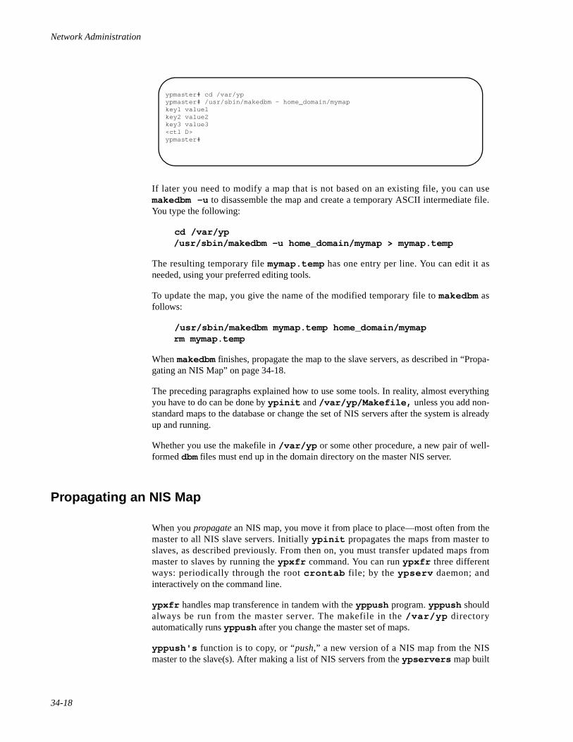
Network Administration
34-18
If later you need to modify a map that is not based on an existing file, you can usemakedbm -u to disassemble the map and create a temporary ASCII intermediate file.You type the following:
cd /var/yp/usr/sbin/makedbm -u home_domain/mymap > mymap.temp
The resulting temporary file mymap.temp has one entry per line. You can edit it asneeded, using your preferred editing tools.
To update the map, you give the name of the modified temporary file to makedbm asfollows:
/usr/sbin/makedbm mymap.temp home_domain/mymaprm mymap.temp
When makedbm finishes, propagate the map to the slave servers, as described in “Propa-gating an NIS Map” on page 34-18.
The preceding paragraphs explained how to use some tools. In reality, almost everythingyou have to do can be done by ypinit and /var/yp/Makefile, unless you add non-standard maps to the database or change the set of NIS servers after the system is alreadyup and running.
Whether you use the makefile in /var/yp or some other procedure, a new pair of well-formed dbm files must end up in the domain directory on the master NIS server.
Propagating an NIS Map 34
When you propagate an NIS map, you move it from place to place—most often from themaster to all NIS slave servers. Initially ypinit propagates the maps from master toslaves, as described previously. From then on, you must transfer updated maps frommaster to slaves by running the ypxfr command. You can run ypxfr three differentways: periodically through the root crontab file; by the ypserv daemon; andinteractively on the command line.
ypxfr handles map transference in tandem with the yppush program. yppush shouldalways be run from the master server. The makefile in the /var/yp directoryautomatically runs yppush after you change the master set of maps.
yppush's function is to copy, or “push,” a new version of a NIS map from the NISmaster to the slave(s). After making a list of NIS servers from the ypservers map built
ypmaster# cd /var/ypypmaster# /usr/sbin/makedbm - home_domain/mymapkey1 value1key2 value2key3 value3<ctl D>ypmaster#
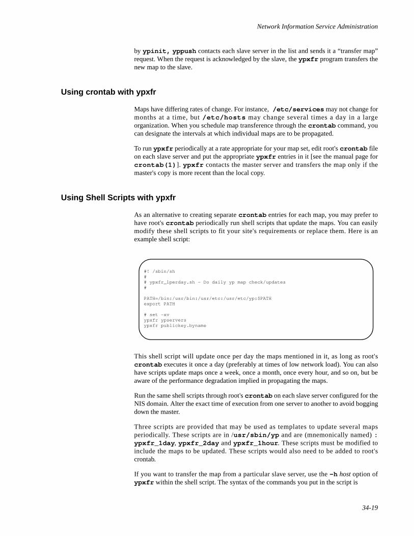
Network Information Service Administration
34-19
by ypinit, yppush contacts each slave server in the list and sends it a “transfer map”request. When the request is acknowledged by the slave, the ypxfr program transfers thenew map to the slave.
Using crontab with ypxfr 34
Maps have differing rates of change. For instance, /etc/services may not change formonths at a time, but /etc/hosts may change several times a day in a largeorganization. When you schedule map transference through the crontab command, youcan designate the intervals at which individual maps are to be propagated.
To run ypxfr periodically at a rate appropriate for your map set, edit root's crontab fileon each slave server and put the appropriate ypxfr entries in it [see the manual page forcrontab(1) ]. ypxfr contacts the master server and transfers the map only if themaster's copy is more recent than the local copy.
Using Shell Scripts with ypxfr 34
As an alternative to creating separate crontab entries for each map, you may prefer tohave root's crontab periodically run shell scripts that update the maps. You can easilymodify these shell scripts to fit your site's requirements or replace them. Here is anexample shell script:
This shell script will update once per day the maps mentioned in it, as long as root'scrontab executes it once a day (preferably at times of low network load). You can alsohave scripts update maps once a week, once a month, once every hour, and so on, but beaware of the performance degradation implied in propagating the maps.
Run the same shell scripts through root's crontab on each slave server configured for theNIS domain. Alter the exact time of execution from one server to another to avoid boggingdown the master.
Three scripts are provided that may be used as templates to update several mapsperiodically. These scripts are in /usr/sbin/yp and are (mnemonically named) :ypxfr_1day , ypxfr_2day and ypxfr_1hour . These scripts must be modified toinclude the maps to be updated. These scripts would also need to be added to root'scrontab.
If you want to transfer the map from a particular slave server, use the -h host option ofypxfr within the shell script. The syntax of the commands you put in the script is
#! /sbin/sh## ypxfr_1perday.sh - Do daily yp map check/updates#
PATH=/bin:/usr/bin:/usr/etc:/usr/etc/yp:$PATHexport PATH
# set -xvypxfr ypserversypxfr publickey.byname
Network Administration
34-20
/usr/sbin/ypxfr -h host mapname
where host is the name of the server with the maps you want to transfer, and mapname isthe name of the requested map. If you use the -h option without specifying host, ypxfrwill try to get the map from the master server.
You can use the -s domain option to transfer maps from another domain to your localdomain. These maps should be essentially the same across domains.
Directly Invoking ypxfr 34
The third method of invoking ypxfr is to run it as a command. Typically, you do this onlyin exceptional situations - for example, when setting up a temporary NIS server to create atest environment, or when trying to make an NIS server that has been out of serviceconsistent with the other servers.
Logging ypxfr's Activities 34
ypxfr's transfer attempts and the results can be captured in a log file. If a file called/var/yp/ypxfr.log exists, results are appended to it. No attempt to limit the size ofthe log file is made. To prevent it from growing indefinitely, empty it from time to time byentering:
cp /var/yp/ypxfr.log /var/yp/ypxfr.log.oldcat /dev/null > /var/yp/ypxfr.log
You can have crontab execute these commands once a week.
To turn off logging, remove the log file.
Password File Updates 34
The exception to the yppush push-on-demand strategy are the passwd maps. Users needto be able to change their passwords without intervention from the system administrator.To change a password when NIS is running, the change must be made on the master serverand distributed to all slave servers before the change is visible to all clients.
The yppasswd(1) utility is provided for a user to change a password on the NIS masterserver. For the change to take affect, the yppasswdd(1M) daemon must be running onthe master server. The script ypinit when invoked for the master will ask whether thisdaemon should automatically be run. To manually enable or disable yppasswdd(1M)the script /etc/rc2.d/S80nis should be modified and the “startyppass” setappropriately.
The yppasswdd(1M) can also force the password maps to be automatically rebuilt andpushed to the slave servers. Some sites may instead choose not to rebuild and distribute themaps automatically. The script ypinit when invoked for the master will ask whether theautomatic propagation should be done. To manually enable or disable yppasswdd(1M)the script /etc/rc2.d/S80nis should be modified and the “yppass_make” setappropriately.
Network Information Service Administration
34-21
Note also that passwd(1) will check to see if the specified password is managed by NISand will invoke yppasswd if this is the case.
Adding New NIS Maps to the Makefile 34
Adding a new NIS map entails getting copies of the map's dbm files into the /var/yp/domain_name directory on each of the NIS servers in the domain. The actual mechanism isdescribed above in “Propagating an NIS Map” on page 34-18. This section only describeshow to update the makefile so that propagation works correctly.
After deciding which NIS server is the master of the map, modify /var/yp/Makefileon the master server so that you can conveniently rebuild the map. As indicatedpreviously, different servers can be masters of different maps. This can, however, lead toadministrative confusion, and it is strongly recommended that you set only one server asthe master of all maps. Actual case-by-case modification is too varied to describe here, buttypically a human-readable ASCII file is filtered through awk, sed, and/or grep tomake it suitable for input to makedbm. Refer to the existing /var/yp/Makefile forexamples.
Use the mechanisms already in place in /var/yp/Makefile when deciding how tocreate dependencies that make will recognize; specifically, the use of .time files allowsyou to see when the makefile was last run for the map.
To get an initial copy of the map, you can have make run yppush on the NIS masterserver. The map must be available globally before clients begin to access it.
NOTE
If the map is available from some NIS servers, but not all, you willencounter unpredictable behavior from client programs.
Adding a New NIS Server to the Original Set 34
After NIS is running, you may need to create an NIS slave server that you did not includein the initial set given to ypinit. The following procedure explains how to do this:
1. Log in to the master server as NIS administrator.
2. Go to the NIS domain directory by typing:
cd /var/yp/ domain_name
3. Disassemble ypservers, as follows:
/usr/sbin/makedbm -u ypservers > /tmp/ temp_file
makedbm converts ypservers from dbm format to the temporary ASCII file/tmp/ temp_file.
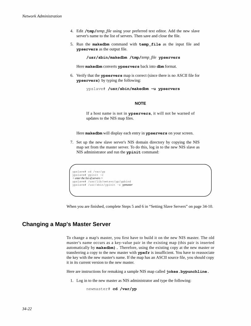
Network Administration
34-22
4. Edit /tmp/ temp_file using your preferred text editor. Add the new slaveserver's name to the list of servers. Then save and close the file.
5. Run the makedbm command with temp_file as the input file andypservers as the output file.
/usr/sbin/makedbm /tmp/ temp_file ypservers
Here makedbm converts ypservers back into dbm format.
6. Verify that the ypservers map is correct (since there is no ASCII file forypservers) by typing the following:
ypslave# /usr/sbin/makedbm -u ypservers
NOTE
If a host name is not in ypservers , it will not be warned ofupdates to the NIS map files.
Here makedbm will display each entry in ypservers on your screen.
7. Set up the new slave server's NIS domain directory by copying the NISmap set from the master server. To do this, log in to the new NIS slave asNIS administrator and run the ypinit command:
When you are finished, complete Steps 5 and 6 in “Setting Slave Servers” on page 34-10.
Changing a Map's Master Server 34
To change a map's master, you first have to build it on the new NIS master. The oldmaster's name occurs as a key-value pair in the existing map (this pair is insertedautomatically by makedbm). Therefore, using the existing copy at the new master ortransferring a copy to the new master with ypxfr is insufficient. You have to reassociatethe key with the new master's name. If the map has an ASCII source file, you should copyit in its current version to the new master.
Here are instructions for remaking a sample NIS map called jokes.bypunchline.
1. Log in to the new master as NIS administrator and type the following:
newmaster# cd /var/yp
ypslave# cd /var/ypypslave# ypinit -c< enter the list of servers >ypslave# /usr/lib/netsvc/yp/ypbindypslave# /usr/sbin/ypinit -s ypmaster
Network Information Service Administration
34-23
2. /var/yp/Makefile must have an entry for the new map before youspecify the map to make. If this isn't the case, edit the makefile now (see“Making the Maps” on page 34-9).
3. Type the following:
newmaster# make jokes.bypunchline
4. If the old master will remain an NIS server, rlogin in to it and edit/var/yp/Makefile. Comment out the section of /var/yp/Makefile that made jokes.bypunchline so that it is no longer madethere.
5. If jokes.bypunchline only exists as a dbm file, remake it on the newmaster by disassembling a copy from any NIS server, then running thedisassembled version through makedbm:
newmaster# cd /var/ypnewmaster# ypcat -k jokes.bypunchline | \ /usr/sbin/makedbm - domain/jokes.bypunchline
Don't forget that jokes.bypunchline should be in the alias file too.
After making the map on the new master, you must send a copy of it to the other slaveservers. However, do not use yppush, as the other slaves will try to get new copies fromthe old master, rather than the new one. A typical method for circumventing this is totransfer a copy of the map from the new master back to the old master. Become NISadministrator on the old master server and type:
oldmaster# /usr/sbin/ypxfr -h newmaster jokes.bypunchline
Now it is safe to run yppush. The remaining slave servers still believe that the oldmaster is the current master. They will attempt to get the current version of the map fromthe old master. When they do so, they will get the new map, which names the new masteras the current master.
If this method fails, you can try this cumbersome but sure-fire option. Log in as NISadministrator on each NIS server and execute the ypxfr command shown above.
Summary of NIS-Related Commands 34
In addition to maps, NIS service also includes specialized daemons, system programs, andcommands, which are summarized below.
ypserv Looks up requested information in a map. ypserv is a daemonthat runs on NIS servers with a complete set of maps. At least oneypserv daemon must be present on the network for NIS serviceto function.
ypbind Initiates binding. ypbind is the NIS binder daemon. It must bepresent on both clients and servers. It initiates binding by finding aypserv process that serves maps within the domain of the
Network Administration
34-24
requesting client. ypserv must run on each NIS server. ypbindmust run on all servers and clients.
ypinit Automatically creates maps for an NIS server from files located in/etc. ypinit also constructs the initial maps that are not builtfrom files in /etc, such as ypservers. Use ypinit to set upthe master NIS server and the slave NIS servers for the first time,as well as to initialize all clients. ypinit is also used toterminate NIS on servers and clients.
make Updates NIS maps by reading the Makefile in /var/yp. Youcan use make to update all maps based on the files in /etc or toupdate individual maps. The manual page ypmake(1M)describes make functionality for NIS.
makedbm Takes an input file and converts it into dbm .dir and .pagfiles—valid dbm files that NIS can use as maps. You can also use makedbm -u to “disassemble” a map, so that you can see thekey-value pairs that comprise it.
ypxfr Moves an NIS map from one server to another, using NIS itself asthe transport medium. You can run ypxfr interactively, orperiodically from a crontab file. It is also called by ypserv toinitiate a transfer.
yppush Copies a new version of an NIS map from the NIS master serverto its slaves. You run it on the master NIS server.
ypset Tells a ypbind process to bind to a named NIS server. ypset isnot for casual use.
yppoll Tells which version of an NIS map is running on a server that youspecify. It also lists the master server for the map.
ypcat Displays the contents of an NIS map.
ypmatch Prints the value for one or more specified keys in an NIS map. Youcannot specify which NIS server's version of the map you are see-ing.
ypwhich Shows which NIS server a client is using at the moment for NISservices, or, if invoked with the -m mapname option, which NISserver is master of each of the maps.
ypupdated Facilitates the updating of NIS information.
yppasswd Utility that allows an NIS user on a client system to change his/herpassword.
rpc.yppasswdd Daemon to allow password updating via yppasswd.
Network Information Service Administration
34-25
Fixing NIS Problems 34
This section explains how to clear problems encountered on networks running NIS. It hastwo parts, one covering problems seen on an NIS client and another covering problemsseen on an NIS server.
Debugging an NIS Client 34
Before trying to debug an NIS client, review the first part of the chapter, which explainsthe NIS environment. Then look for the subheading in this section that best describes yourproblem.
Hanging Commands on the Client 34
The most common problem of NIS clients is for a command to hang and generate consolemessages such as:
yp: server not responding for domain <domainname>. Still trying
Sometimes many commands begin to hang, even though the system as a whole seemsnormal and you can run new commands.
The message above indicates that ypbind on the local machine is unable to communicatewith ypserv in the domain domainname. This happens when a machine running ypservhas crashed or is down or unavailable for any reason. It may also occur if the network orNIS server is so overloaded that ypserv cannot get a response back to the client'sypbind within the time-out period.
Under these circumstances, every client on the network will experience the same orsimilar problems. The condition is temporary in most cases. The messages will usually goaway when the NIS server reboots and restarts ypserv, or when the load on the NISserver or network itself decreases.
However, commands may hang and require direct action to clear them. The following listdescribes the causes of such problems and gives suggestions for fixing them:
• The NIS client has not set, or has incorrectly set, the machine's domainname. Clients must use a domain name that the NIS servers know.
• On the client, type domainname to see which domain name is set.Compare that with the actual domain name in /var/yp on the NIS masterserver. If a machine's domain name is not the same as the server's, themachine's domain name entry in its installation scripts is incorrect. Log inas NIS administrator, edit the client's installation scripts, and correct thedomainname entry. This assures the domain name is correct every timethe machine boots. Then set domainname manually by typing thefollowing:
domainname good_domain_name
Network Administration
34-26
• If commands still hang, make sure the server is up and running. Checkother machines on your local network. If several clients also haveproblems, suspect a server problem. Try to find a client machine behavingnormally, and type the ypwhich command on it. If ypwhich does notrespond, kill it and go to a terminal on the NIS server. Type the following:
ypserver# ps -ef | grep ypypserver# kill -9 pid
where pid is the process-ID for ypbind . Look for ypserv and ypbindprocesses. If a ypserv process is running, type
ypserver# ypwhich
on the NIS server. If ypwhich does not respond, ypserv has probablyhung, and you should restart it. Type the following while logged in as NISadministrator:
ypserver# kill -9 [ypserv's pid # from ps]ypserver# /usr/lib/netsvc/yp/ypserv
If ps shows no ypserv process running, start one up.
• If the server's ypbind daemon is not running, start it up by typing the fol-lowing:
ypserver# /usr/lib/netsvc/yp/ypbind
Notice that if you run ypbind and you type ypwhich immediately,ypwhich will return the error message not found in all cases. Runypwhich again; it should now return the name of a server.
• If commands still hang, you may try the following:
1. Kill the existing ypbind:
ps -ef | grep ypbind
2. Restart ypbind with the ypset option that permits root to changethe server:
ypbind -ypsetme
3. Reset the server to one you know is reliable:
ypset servername
NIS Is Unavailable 34
When most machines on the network appear to be behaving normally, but one client can-not receive NIS service, that client may experience many different symptoms. Forexample, some commands appear to operate correctly while others terminate with an errormessage about the unavailability of NIS. Other commands limp along in a backup-strategymode particular to the program involved. Still other commands or daemons crash with
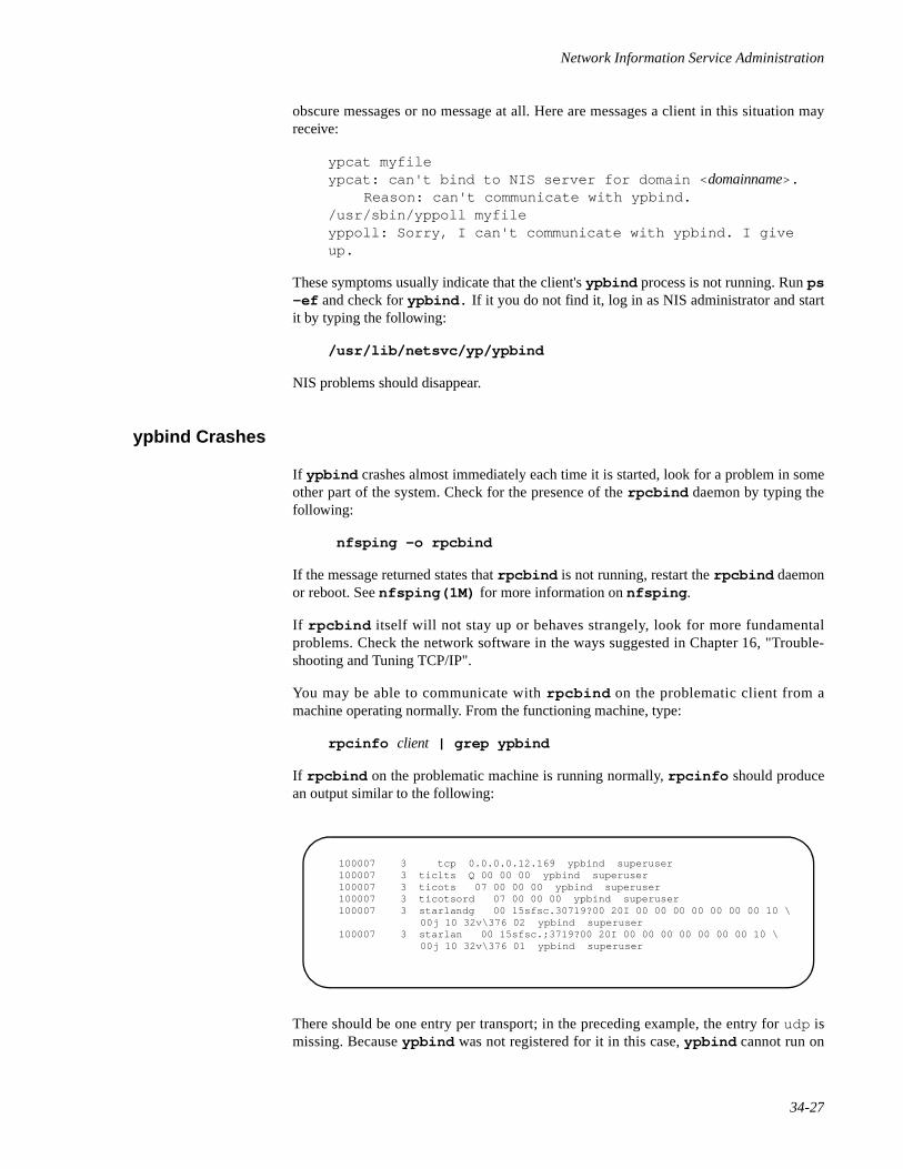
Network Information Service Administration
34-27
obscure messages or no message at all. Here are messages a client in this situation mayreceive:
ypcat myfileypcat: can't bind to NIS server for domain < domainname>.
Reason: can't communicate with ypbind./usr/sbin/yppoll myfileyppoll: Sorry, I can't communicate with ypbind. I give up.
These symptoms usually indicate that the client's ypbind process is not running. Run ps-ef and check for ypbind. If it you do not find it, log in as NIS administrator and startit by typing the following:
/usr/lib/netsvc/yp/ypbind
NIS problems should disappear.
ypbind Crashes 34
If ypbind crashes almost immediately each time it is started, look for a problem in someother part of the system. Check for the presence of the rpcbind daemon by typing thefollowing:
nfsping -o rpcbind
If the message returned states that rpcbind is not running, restart the rpcbind daemonor reboot. See nfsping(1M) for more information on nfsping .
If rpcbind itself will not stay up or behaves strangely, look for more fundamentalproblems. Check the network software in the ways suggested in Chapter 16, "Trouble-shooting and Tuning TCP/IP".
You may be able to communicate with rpcbind on the problematic client from amachine operating normally. From the functioning machine, type:
rpcinfo client | grep ypbind
If rpcbind on the problematic machine is running normally, rpcinfo should producean output similar to the following:
There should be one entry per transport; in the preceding example, the entry for udp ismissing. Because ypbind was not registered for it in this case, ypbind cannot run on
100007 3 tcp 0.0.0.0.12.169 ypbind superuser 100007 3 ticlts Q 00 00 00 ypbind superuser 100007 3 ticots 07 00 00 00 ypbind superuser 100007 3 ticotsord 07 00 00 00 ypbind superuser 100007 3 starlandg 00 15sfsc.30719?00 20I 00 00 00 00 00 00 00 10 \
00j 10 32v\376 02 ypbind superuser 100007 3 starlan 00 15sfsc.;3719?00 20I 00 00 00 00 00 00 00 10 \
00j 10 32v\376 01 ypbind superuser
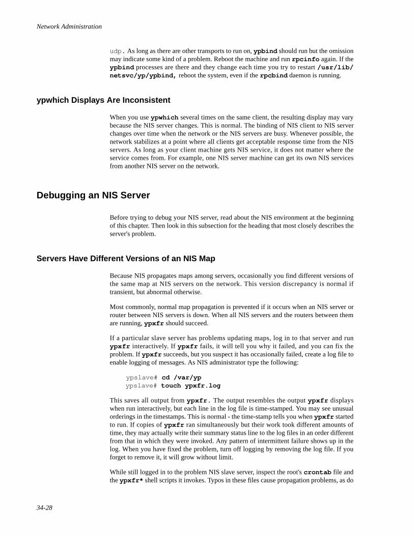
Network Administration
34-28
udp. As long as there are other transports to run on, ypbind should run but the omissionmay indicate some kind of a problem. Reboot the machine and run rpcinfo again. If theypbind processes are there and they change each time you try to restart /usr/lib/netsvc/yp/ypbind, reboot the system, even if the rpcbind daemon is running.
ypwhich Displays Are Inconsistent 34
When you use ypwhich several times on the same client, the resulting display may varybecause the NIS server changes. This is normal. The binding of NIS client to NIS serverchanges over time when the network or the NIS servers are busy. Whenever possible, thenetwork stabilizes at a point where all clients get acceptable response time from the NISservers. As long as your client machine gets NIS service, it does not matter where theservice comes from. For example, one NIS server machine can get its own NIS servicesfrom another NIS server on the network.
Debugging an NIS Server 34
Before trying to debug your NIS server, read about the NIS environment at the beginningof this chapter. Then look in this subsection for the heading that most closely describes theserver's problem.
Servers Have Different Versions of an NIS Map 34
Because NIS propagates maps among servers, occasionally you find different versions ofthe same map at NIS servers on the network. This version discrepancy is normal iftransient, but abnormal otherwise.
Most commonly, normal map propagation is prevented if it occurs when an NIS server orrouter between NIS servers is down. When all NIS servers and the routers between themare running, ypxfr should succeed.
If a particular slave server has problems updating maps, log in to that server and runypxfr interactively. If ypxfr fails, it will tell you why it failed, and you can fix theproblem. If ypxfr succeeds, but you suspect it has occasionally failed, create a log file toenable logging of messages. As NIS administrator type the following:
ypslave# cd /var/ypypslave# touch ypxfr.log
This saves all output from ypxfr. The output resembles the output ypxfr displayswhen run interactively, but each line in the log file is time-stamped. You may see unusualorderings in the timestamps. This is normal - the time-stamp tells you when ypxfr startedto run. If copies of ypxfr ran simultaneously but their work took different amounts oftime, they may actually write their summary status line to the log files in an order differentfrom that in which they were invoked. Any pattern of intermittent failure shows up in thelog. When you have fixed the problem, turn off logging by removing the log file. If youforget to remove it, it will grow without limit.
While still logged in to the problem NIS slave server, inspect the root's crontab file andthe ypxfr* shell scripts it invokes. Typos in these files cause propagation problems, as do
Network Information Service Administration
34-29
failures to refer to a shell script within /var/spool/cron/crontabs/root, orfailures to refer to a map within any shell script.
Also, make sure that the NIS slave server is in the map ypservers within the domain. Ifit is not, it still operates perfectly as a server, but yppush will not tell it when a new copyof a map exists.
If the NIS slave server's problem is not obvious, you can work around it while you debugit using rcp or tftp to copy a recent version of the inconsistent map from any healthyNIS server. You must not do this remote copy as root, but you can probably do it whilelogged in as daemon. For instance, here is how you might transfer the map busted :
Here the * character has been escaped in the command line so that it will be expanded onypmaster, instead of locally on ypslave. Notice that the map files should be ownedby root, so you must change their ownership after the transfer.
ypserv Crashes 34
When the ypserv process crashes almost immediately and does not stay up even withrepeated activations, the debug process is virtually identical to that previously described in“ypbind Crashes” on page 34-27. Check for the existence of the rpcbind daemon asfollows:
ypserver# ps -ef | grep rpcbind
Reboot the server if you do not find the daemon. If it is there, type
rpcinfo yp_server | grep ypserv
and look for output similar to the following:
ypslave# chmod go+w /var/yp/mydomainypslave# su daemonrcp ypmaster:/var/yp/mydomain/busted.\* /var/yp/mydomainexitypslave# chown root /var/yp/mydomain/busted.*ypslave# chmod go-w /var/yp/mydomain
Network Administration
34-30
Your machine will have different port numbers. As in the case of ypbind, there shouldbe one entry per transport. If a transport is missing, ypserv has been unable to register itsservices with it. Reboot the machine. If the ypserv processes are there, and they changeeach time you try to restart /usr/lib/netsvc/yp/ypserv, reboot the machine.
Turning off NIS 34
If ypserv on the master is disabled, you can no longer update any of the NIS maps. Onthe other hand, if there is no ypserv daemon running but clients have ypbind running,machines may hang indefinitely until they find a ypserv .
To turn off NIS services safely, make sure all the clients stop running ypbind beforeinvoking ypinit -t to terminate the NIS daemons and make changes to NISconfiguration files.
100004 2 tcp 0.0.0.0.12.168 ypserv superuser 100004 2 udp 0.0.0.0.4.8 ypserv superuser 100004 2 ticlts B 00 00 00 ypserv superuser 100004 2 ticots 06 00 00 00 ypserv superuser 100004 2 ticotsord 06 00 00 00 ypserv superuser 100004 2 starlandg 00 15sfsc.2>219?00 20I 00 00 00 00 00 00 00 10 \
00j 10 32v\376 02 ypserv superuser 100004 2 starlan 00 15sfsc.31319?00 20I 00 00 00 00 00 00 00 10 \
00j 10 32v\376 01 ypserv superuser
Glossary-1
Glossary
3535
address
A unique number that identifies a machine on a network (see IP address).
ARP
Address Resolution Protocol, a protocol that maps an IP address to its correspondingEthernet address.
ARPANET
The Advanced Research Projects Agency funded network, for which TCP/IP wasoriginally developed (see DoD Internet).
binding
The process by which a client locates the server that shares the information desired, andthen sets up communication with that server.
bridge
A device used at the Data Link layer that selectively copies packets between networks ofthe same type.
caller process
A process that uses RPC to have another process execute a procedure call.
client
A machine that uses the resources of another machine; a machine can be both a client,utilizing resources that reside on other machines, and a server, making local resourcesavailable to other machines.
credentials
Information that is used to prove that something is as it claims to be—for example, anidentification badge. (See also “verifiers”).
daemon
A program that runs autonomously, performing actions that facilitate more complexoperations; for example, the mail service is run by several daemons, all of which workmore or less without human oversight.
Network Administration
Glossary-2
DARPA Internet
The Defense Advanced Research Projects Agency Internet (see Internet).
Data Encryption Standard (DES)
A standard cryptography algorithm used to ensure data security.
datagram
Transmission unit at the IP level.
diskless client
A machine that has no local disk and is, therefore, dependent upon the server for all its filestorage. Diskless machines can act only as clients, never as servers.
DDN Internet
The Defense Data Network Internet (see Internet).
DoD Internet
The Department of Defense Internet, a wide area network to which the ARPANETbelongs (see Internet).
domain
An administrative entity, typically consisting of several machines, that joins a larger net-work.
Domain Name Service
The name service of the Internet Protocol family.
file handle
A key obtained by a client from a server to facilitate all further requests between that clientand server.
gateway
An IP router (see router).
group identification number (GID)
A number that refers to a specific group of users on a system. Each user can belong to oneor more groups.
header
Information attached to the beginning of data. Headers usually contain information aboutthe following data to aid in processing it.

Glossary
Glossary-3
hierarchy
A part or all of a file structure. The term “hierarchy” refers to both the directories of thefile structure, and the files within the structure.
host
An individual machine on a network.
hung
When a process has been stopped abnormally, with no way to restart that process.
ICMP
Internet Control Message Protocol, which is responsible for handling errors and printingerror messages.
Internet
A wide area network originally funded by the Department of Defense, which utilizes TCP/IP for data interchange. The term Internet is used to refer to any and all of ARPANET,DARPANET, DDN, or DoD Internets.
internetwork
A group of networks connected by routers.
IP
Internet Protocol, which allows host-to-host datagram delivery.
IP address
A unique number that identifies each host in a network.
IP network number
A unique number that identifies each IP network (See net number).
IP router
See router.
local machine
The machine you are currently logged in to, as opposed to a remote machine.
map
A file that contains a listing of mount points and their corresponding resources. The mapsare used by the automounter program to locate where a file structure should be mountedwhen it is needed.
Network Administration
Glossary-4
mount
The action a client performs to access files in a server's shared directories. When a clientmounts a resource, it does not copy that resource, but rather accesses the resource acrossthe network as if it were a local file system.
mount point
A location within the directory tree through which a machine accesses a mountedresource. You need to create and/or specify a mount point when you mount a remoteresource. The mount point for a resource is usually an empty directory.
netname
A string of printable characters created by concatenating the name of the operatingsystem, a user ID, and a domain name. Netnames are used in DES authentication.
Network File System (NFS)
A service that enables machines to share file resources across a network.
Network Information Service (NIS)
A distributed naming service used to identify and locate objects and resources accessibleto a computing community. It provides a uniform, network-wide storage and retrievalmethod that is both protocol- and media-independent.
NIS Server
A machine with a disk that stores a set of NIS maps that it makes available to networkhosts.
network mask
A number used by software to separate the local subnet address from the rest of a given IPaddress.
network protocols
Sets of rules that explain how software and hardware should interact within a network totransmit information.
NIC
Network Information Center, a service that administers IP network numbers and domainnames.
NIC handle
A unique NIC database identifier assigned to a network's administrator and technicalcontact.

Glossary
Glossary-5
node name
The name you assign to your computer to use for communications needs. Networkingsoftware, such as Basic Networking Utilities, use this name to identify your machine.
packet switching
A concept which states that a network transmits packets over connections that last only forthe duration of the transmission.
packets
A piece of data smaller than a datagram. A datagram is made up of one or more packets.
port numbers
Numbers used by UDP and TCP to identify the end points of communication.
privileged user
In a system with Enhanced Security installed and the Least Privileged Mechanism (LPM)running, a privileged user is a user in the NET (network administrator's) role. Seeadminuser(1M) . Otherwise, root is the privileged user.
process identification number (PID)
A number that identifies a process to the operating system. Every process has a PID bywhich it is referenced.
public key cryptography
A cipher system that uses a published public key and an encoded secret key.
RARP
Reverse Address Resolution Protocol, a protocol that is the reverse of ARP. RARP mapsEthernet addresses to its corresponding IP addresses.
Remote File Sharing (RFS)
A service that enables machines to share resources across a network. RFS is no longersupplied as part of the operating system.
remote machine
The machine to which you are connected across the network.
Remote Procedure Call (RPC)
Procedures that provide the means by which one process (the caller) can have anotherprocess (the server) execute a procedure call as if the caller had done so itself locally.
Network Administration
Glossary-6
resource
A file system, a portion of a file system, a directory, or a single file shared by a serveracross a network.
router
A device that forwards (routes) packets of a protocol family, from one network to another.
run level
A user mode, also called a run state or init state.
server
A machine that shares file systems or portions of file systems; a machine can be both aserver, making local resources available to other machines, and a client, utilizing resourcesthat reside on other machines. Individual files may be shared if both the server and clientare using NFS.
server process
A process that receives directives from a caller process to execute procedures locally.
share
The action a server machine performs to allow some or all of its resources to becomeavailable to other hosts.
subnet
An administrative division of a network into smaller networks.
subnet number
The part of an IP address that refers to the specific subnet desired.
TCP
Transmission Control Protocol.
TCP/IP
A term used to refer to the entire Internet family of protocols, consisting of the names ofthe two most important protocols.
transport provider
The software that provides a path through which network applications can communicate.
Glossary
Glossary-7
UDP
User Datagram Protocol, a protocol at the same layer as TCP, but withoutacknowledgment of transmission and therefore unreliable.
unsharing
Making a shared local resource unavailable to remote systems.
user/group ID number
Every user and group name has a corresponding number that is used by the UNIXoperating system to handle permissions to files, directories, devices, and so on. Thesenumbers are defined in the third field of the /etc/passwd or /etc/group files,respectively.
user/group name
The names associated with each local user and group that is allowed access to yourcomputer. This information can be found in the first field of the /etc/passwd or /etc/group files, respectively.
user identification number (UID)
A number that identifies a user to the operating system. Every user has a unique numberthat identifies that user to the operating system.
verifiers
Information that is used to prove that credentials are valid.
virtual circuits
An apparent connection between processes which is facilitated by TCP. A virtual circuitallows applications to talk to each other as if they had a physical circuit.
zones
Administrative boundaries within a domain, often made up of one or more sub-domains(see domain).

Network Administration
Glossary-8
Index-1
Symbols
/etc/, cs/auth 4-8-4-9/etc/, dfs/dfstab(4) 20-4, 22-1, 22-2-22-3, 25-3, 26-2,
26-3, 28-2, 28-7, 29-6/etc/, dfs/fstypes(4) 20-4, 21-3-21-4, 25-3, 26-2/etc/, dfs/sharetab(4) 20-4, 25-3, 28-6/etc/, hosts(4) 3-2, 4-7, 5-3, 8-3/etc/, iaf/cr1/keys 5-1/etc/, iaf/serve.alias 1-7, 4-1, 4-4/etc/, iaf/serve.allow 1-6, 4-1, 4-3, 5-4, 5-6, 7-58, 8-3/etc/, idmap/attrmap 6-16, 6-18/etc/, idmap/cr1/idata 6-6, 6-8, 6-10, 6-11/etc/, idmap/cr1/uidata 6-6, 6-11/etc/, mnttab(4) 20-4, 28-2, 28-3, 30-13/etc/, net/ticots/hosts 4-8/etc/, net/ticots/services 4-8/etc/, net/transport 1-6/etc/, net/transport/hosts 3-2, 3-3-3-4, 5-3/etc/, net/transport/services 3-2, 3-3-3-4, 5-3/etc/, netconfig(4) 1-5, 2-2-2-5, 3-1/etc/, publickey(4) 29-6, 33-1, 33-3, 33-4, 33-5, 33-6-
33-8/etc/, rc2.d/S75rpc 33-2-33-3/etc/, rexec/services 1-8, 8-4, 8-6/etc/, services(4) 3-2, 5-3/etc/, uucp 1-8/etc/, uucp/Config 7-21/etc/, uucp/Devconfig 7-18/etc/, uucp/Devices 7-22-7-28/etc/, uucp/Dialcodes 7-38-7-39/etc/, uucp/Dialers 7-29-7-31/etc/, uucp/Grades 7-39-7-41/etc/, uucp/Limits 7-19-7-20/etc/, uucp/Permissions 7-10-7-18/etc/, uucp/Poll 7-39/etc/, uucp/Sysfiles 7-19/etc/, uucp/Systems 7-31-7-38/etc/, vfstab(4) 20-4, 22-4, 22-5, 22-6, 22-7, 25-4-25-5,
26-4, 28-2, 28-5, 28-8, 29-6, 30-1, 30-2, 30-11, 30-14
/etc/mail/charset 9-17/etc/uucp/paths(1), routing 9-8/tmp_mnt, special directory (NFS) 30-1
/usr, /include/netconfig.h 2-3/usr, /lib/1af/cr1 6-1/usr, /lib/cron/log 7-65/usr, /lib/iaf/cr1/scheme 5-1/usr, /lib/uucp/remote.unknown 7-6-7-7/var, /mail 9-1, 9-5/var, spool/smtpq/LOG 9-10/var/, adm/log/cs.debug 4-10/var/, adm/log/cs.log 4-9/var/, iaf/cr1 5-1/var/, spool/uucp/.Admin/account 7-49/var/, spool/uucp/.Admin/command 7-44/var/, spool/uucp/.Admin/errors 7-46/var/, spool/uucp/.Admin/Foreign 7-56/var/, spool/uucp/.Admin/perflog 7-52-7-55/var/, spool/uucp/.Admin/security 7-50-7-51/var/, spool/uucp/.Admin/xferstats 7-47-7-48/var/, spool/uucp/.Log 7-45
A
Accept 9-8account log (BNU) 7-49Address Resolution Protocol (ARP) 11-2, 11-4address style translation (see mail(1)) 9-3administrative files, BNU 7-8alias lists, mail(1) 9-6anon, option to NFS share(1M) command 25-4Appended Local Files 34-14application layer, TCP/IP 11-5-11-6ARP 11-4ARPANET 11-2attradmin(1M) 6-4-6-5, 6-17-6-21attribute maps 6-17-6-25attribute maps, adding an entry to 6-17-6-19attribute maps, checking and fixing 6-20-6-21attribute maps, deleting 6-20attribute maps, deleting an entry in 6-20attribute maps, displaying information 6-21attribute maps, setting up 6-18authentication scheme See cr1 4-2authentication scheme, registering client machine 4-3-
4-4
Index

Network Administration
Index-2
authentication, DES 29-2authentication, ENIGMA 1-3, 5-1authentication, RPC 29-1authentication, UNIX 29-2auto.home map 30-8automount(1M) (NFS), 30-1, 30-11-30-13automounter (NFS), 30-1automounter (NFS), debugging 30-14-30-16automounter (NFS), hierarchical mounts 30-6automounter (NFS), how it works 30-1automounter (NFS), invoking 30-11automounter (NFS), purpose of 30-1automounter (NFS), special mount point 30-1automounter (NFS), updating the mount table 30-13automounter maps (NFS), 30-2automounter maps (NFS), conventions 30-2automounter maps (NFS), modifying 30-13automounter maps (NFS), preparing 30-2-30-10automounter maps (NFS), specifying multiple locations
30-7automounter maps (NFS), specifying multiple mounts
30-6-30-7automounter maps (NFS), using environment variables
30-10automounter maps (NFS), using substitution 30-9, 30-10automounter maps (NFS), writing a direct map 30-4-
30-11automounter maps (NFS), writing a master map 30-3-
30-4automounter maps (NFS), writing an indirect map 30-5-
30-6
B
bang style addressing 9-1Basic Networking Utilities See BNU 7-1binding, (NIS) 34-5-34-6biod(1M) 28-2, 28-3-28-4, 28-8BNU administrative support files 7-41-7-43BNU administrative support files, (C.) work files 7-42-
7-43BNU administrative support files, (D.) authentication
file 7-43BNU administrative support files, (D.) data files 7-43BNU administrative support files, (LCK.) lock files 7-42BNU administrative support files, (P.) checkpoint files
7-42BNU administrative support files, (TM.) temporary data
files 7-41BNU administrative support files, (X.) execute files
7-43BNU database support files 7-7-7-8
BNU database support files, Config file 7-7, 7-21BNU database support files, Devconfig file 7-7, 7-18BNU database support files, Devices file 7-7, 7-22-7-28BNU database support files, Dialcodes file 7-7, 7-38-
7-39BNU database support files, Dialers file 7-7, 7-29-7-31BNU database support files, Grades file 7-7, 7-39-7-41BNU database support files, LIDAUTH.map file 7-20BNU database support files, Limits file 7-7, 7-19BNU database support files, Permissions file 7-8, 7-10-
7-18BNU database support files, Poll file 7-8, 7-39BNU database support files, remote.unknown file 7-6-
7-7BNU database support files, RLID.map file 7-20BNU database support files, Sysfiles file 7-8, 7-19BNU database support files, Systems file 7-8, 7-31-7-38BNU log files 7-43-7-56BNU log files, account 7-49BNU log files, command 7-44BNU log files, errors 7-46BNU log files, Foreign (unknown system) 7-56BNU log files, perflog 7-52-7-55BNU log files, perflog (conn) 7-53BNU log files, perflog (xfer) 7-54-7-55BNU log files, security 7-50-7-51BNU log files, security (rexe) 7-51BNU log files, security (xfer) 7-50BNU log files, system history 7-45BNU log files, xferstats (transfer) 7-47-7-48BNU, administration 7-8-7-63BNU, administrative programs 7-5-7-6BNU, check basic information 7-67BNU, components 7-4-7-8BNU, daemons 7-6-7-7BNU, debugging 7-9, 7-66-7-68BNU, escape characters 7-36-7-37BNU, log files 7-8BNU, maintenance 7-63-7-66BNU, maintenance (automatic) 7-63-7-65BNU, maintenance (manual) 7-65BNU, networking programs 7-4-7-7BNU, perflog (conn) 7-53BNU, perflog (xfer) 7-54-7-55BNU, poll remote machines 7-39BNU, procedural overview 1-5-1-8BNU, process diagram 7-2BNU, queue jobs for remote machines 7-39-7-41BNU, security 7-6-7-7, 7-10-7-18, 7-50-7-51BNU, security (rexe) 7-51BNU, security (xfer) 7-50BNU, setting up 1-7, 1-8BNU, support files 7-7-7-8BNU, unknown calling machines 7-6-7-7

Index
Index-3
BNU, user programs 7-4-7-5booting problems, NFS 29-7Building a Configuration File 10-13Building Mailer Descriptions 10-16
C
C and F - Define Classes 10-4character set 9-17chkey(1) 33-8Choosing NIS Servers 34-9circuit switching network 11-3Class A addresses 11-7Class B addresses 11-7Class C addresses 11-7class field record client(s), (NIS) 34-5, 34-11, 34-25-
34-27command log (BNU) 7-44common key 29-2Config file (BNU) 7-21Configuration File Syntax and Semantics 10-3connection server 4-1-4-11, 7-2connection server, application interface 4-1-4-2connection server, auth (authentication scheme file) 4-8-
4-9connection server, client machine administration 4-3-
4-6connection server, components of 4-1connection server, cs.debug (debug file) 4-10-4-11connection server, cs.log (log file) 4-9-4-10connection server, server machine administration 4-2-
4-3connection server, setting up 1-6-1-7connection server, setting up for CS dialer type-client
machine 7-58-7-59connection server, setting up for CS dialer type-server
machine 7-59-7-60connection server, setting up when CS dialer type not
used-client machine 7-61-7-62connection server, setting up when CS dialer type not
used-server machine 7-62-7-63conversation key 29-2cr1, administration of 5-1-5-10cr1, bilateral authentication scheme 5-1-5-10cr1, client/server exchanges 5-2cr1, command alternatives to 5-5cr1, components 5-1cr1, cryptkey(1) 1-7, 5-5, 5-7, 5-9-5-10, 8-3cr1, daemon 5-7cr1, identification and authentication facility 1-3-1-4cr1, key creating a master 5-8cr1, key database 5-8
cr1, key management daemon 5-7-5-8cr1, keymaster(1M) daemon 1-7, 5-1, 5-5, 5-7-5-8cr1, master key 5-7cr1, menu 5-4cr1, registering with a port monitor 5-6cr1, registering with the connection server 5-6cr1, setting up authentication scheme 1-7cr1, setting up the key database 5-8-5-10cr1, setting up the RLID.map file 6-22-6-25cr1, shared keys 5-1-5-2credentials, in RPC authentication 29-2cryptkey(1) 1-7, 5-5, 5-7, 5-9-5-10, 8-3cs_perror See cs_connect(3N) 1-6ct(1C) 7-1, 7-4, 7-37cu(1C) 7-1, 7-4, 7-8, 7-18, 7-19, 7-28, 7-37, 7-38, 7-66,
7-67
D
D - Define Macro 10-4daemons (network) 7-6-7-7daemons (network), biod(1M) 28-2, 28-3-28-4, 28-8daemons (network), lockd(1M) 28-2, 31-2, 31-3daemons (network), mountd(1M) 28-2, 28-3, 28-6daemons (network), nfsd(1M) 28-1, 28-3, 28-7daemons (network), rlogind(1M) 31-2daemons (network), rpcbind(1M) 28-2, 28-4-28-6, 33-8,
34-27-34-28, 34-29daemons (network), statd(1M) 28-2, 31-2, 31-4daemons (NIS), 34-2Data Encryption Standard (DES), authentication 29-2data link layer, TCP/IP 11-4datagram 11-4debugging, NFS 28-1-28-9debugging, NIS 34-25-34-30Default NIS Maps 34-12Deny 9-8DES authentication 29-2Devconfig file (BNU) 7-18Devices file (BNU) 7-22-7-28Devices, Class field 7-23Devices, Dialer-Token-Pairs field 7-24-7-27Devices, Line field 7-23Devices, Line2 field 7-23Devices, Protocol 7-27-7-28Devices, Type field 7-22dfmounts(1M) 20-5, 22-10-22-11dfmounts(1M), NFS 27-2DFS Administration 20-3DFS Administration, commands 20-4DFS Administration, files 20-4DFS Administration, menus 23-1-23-3

Network Administration
Index-4
DFS Administration, operating states (init states) 21-4dfshares(1M) 20-4, 22-9-22-10dfshares(1M), NFS 25-3, 26-1, 27-1dfstab(4) 20-4, 22-1, 22-2-22-3, 25-3, 26-3, 28-2, 28-7,
29-6dfstab(4), used as input to shareall(1M) 22-3, 26-2diagnostics, automounter problems (NFS) 30-14-30-16diagnostics, fixing hung NFS programs 28-7diagnostics, NFS client problems 28-5diagnostics, NFS mounting problems 28-5-28-7diagnostics, NFS server problems 28-4-28-5Dialcodes file (BNU) 7-38-7-39Dialers file (BNU) 7-29-7-31diff(1) 2-1Distributed File System (DFS), administration 21-1-
21-4, 22-1-22-11Distributed File System (DFS), changing default
package 21-3Distributed File System (DFS), commands and files
20-3-20-5, 22-1-22-11Distributed File System (DFS), displaying information
about 22-8-22-11Distributed File System (DFS), installing software 21-1Distributed File System (DFS), management menu tree
23-1Distributed File System (DFS), menu options 23-2-23-3Distributed File System (DFS), mounting and
unmounting remote resources 22-4-22-8Distributed File System (DFS), organization 20-1Distributed File System (DFS), overview of 20-3-20-5Distributed File System (DFS), setting a default type
21-3Distributed File System (DFS), setting up 21-1-21-4Distributed File System (DFS), sharing and unsharing
resources 22-1-22-4Distributed File System (DFS), starting 21-4Distributed File System (DFS), system V file sharing
20-2-20-3DLM 25-5Domain Name Service (DNS) 3-3Domain Name Service (DNS), TCP/IP 11-5domain NIS/RPC 29-6, 33-5, 33-6, 34-7-??domain NIS/RPC, names 34-4domain TCP/IP, levels of Internet 11-10-11-12domain TCP/IP, local administrative 11-12domain TCP/IP, registering 11-13domain TCP/IP, root-level 11-12domain TCP/IP, second-level 11-12domain TCP/IP, selecting a name 11-12domain TCP/IP, top-level 11-12domain, style addressing 9-1, 9-4dynamically loadable modules 25-5
E
Enabling Sendmail 10-18encryption keys 29-3enhanced security package 12-29ENIGMA encryption 1-3, 5-1environment variables (NFS) 30-10error messages, See debugging 1-6error reporting routine 1-6errors log (BNU) 7-46escape character 7-26Ethernet 11-3
F
File Transfer Protocol (FTP) 11-5Files Managed by NIS 34-6Foreign log (BNU) 7-56fstypes(4) 20-4, 25-3, 26-2fstypes(4), changing defaults 21-3-21-4
G
GID map 6-17Grades 7-7Grades file (BNU) 7-39-7-41Grades file (BNU), default 7-41Grades file (BNU), ID-list 7-40Grades file (BNU), Job-size field 7-39-7-41Grades file (BNU), System-job-grade field 7-39-7-41Grades file (BNU), User-job-grade field 7-39-7-41Group File 34-15
H
H - Define Header 10-5hard mounts 26-4, 28-5hierarchical mounts (NFS) 30-6host address database 8-2host ID 11-7hosts(4) 3-2, 4-7, 5-3, 8-3
I
ID Mapping, administration of 6-1-6-25

Index
Index-5
ID Mapping, attribute mapping menu 6-4ID Mapping, attribute maps 6-16-6-21ID Mapping, command alternatives to attribute mapping
menu 6-4ID Mapping, command alternatives to name mapping
menu 6-3ID Mapping, command alternatives to second level
attribute mapping menu 6-5ID Mapping, command alternatives to second-level
name mapping menu 6-3ID Mapping, login maps 6-5-6-16ID Mapping, REXEC 8-2ID Mapping, setting up 1-7ID Mapping, setting up the RLID.map file 6-22-6-25ID Mapping, sub-menu for attribute mapping
administration 6-4ID Mapping, sub-menu for name mapping
administration 6-3ID Mapping, user-controlled maps 6-14-6-16idadmin(1M) 1-7, 6-7idata file, adding an entry to 6-6idata file, administration of 6-6-6-12idata file, checking and fixing 6-11-6-12idata file, displaying information 6-12idata file, setting up 6-7-6-8Identification and Authentication Facility, (IAF) 1-3-1-4Integration of Maps with Local files 34-13Internet 11-2Internet Control Message Protocol (ICMP) 11-2, 11-4Internet domains 11-10Internet Protocol (IP) 11-2, 11-4Internet Protocol (IP), header 11-4internet protocol suite 11-2Introduction to Sendmail 10-1invocation function, identification and, authentication
facility and 1-3IP addresses 11-6IP, See Internet Protocol 1-3
K
keymaster(1M) daemon 5-7keys See encryption keys 29-3keyserv(1M) 29-6, 33-3, 33-4, 33-5
L
LHS 10-4LIDAUTH.map 4-4-4-6LIDAUTH.map file (BNU) 7-20
Limits file (BNU) 7-19-7-20listen port monitor 1-2-1-3listen port monitor, registering cr1 with 5-6listen port monitor, registering REXEC with 8-3-8-4listen port monitor, setting up 1-6loadable modules 25-5local administrative TCP/IP domains 11-12local_resources submenu (DFS) 23-2localmail 9-14-9-15lock manager, NFS 31-1-31-4lockd(1M) 28-2, 31-2, 31-3log files BNU 7-8, 7-43-7-56log files BNU, account 7-49log files BNU, cleaning up 7-65log files BNU, command 7-44log files BNU, errors 7-46log files BNU, Foreign 7-56log files BNU, perflog 7-52-7-55log files BNU, perflog (conn) 7-53log files BNU, perflog (xfer) 7-54-7-55log files BNU, security 7-50-7-51log files BNU, security (rexe) 7-51log files BNU, security (xfer) 7-50log files BNU, summary of 7-66log files BNU, system history 7-45log files BNU, xferstats (transfer) 7-47-7-48login maps, setting up 6-5-6-16logins, adding 7-56logs, mail 9-7logs, SMTP (see mail(1)) 9-10
M
M - Define Mailer 10-5Mail and Sendmail Aliases File 34-15mail header rewriting 9-11-9-14mail service, addressing styles 9-3mail service, administering alias lists 9-6mail service, administration files 9-2mail service, controlling access 9-8-9-9mail service, establishing a cluster or gateway 9-4mail service, establishing a smarter host 9-3mail service, establishing domain addresses 9-4mail service, logging 9-7mail service, path translation 9-8mail service, sharing of services 9-5-9-6mail service, Simple Mail Transfer Protocol (SMTP)
9-1, 9-9-9-11Mail vs. Sendmail 10-1mail(1) 10-1mail(1), address style translation 9-3mail(1), administration 9-1-9-11

Network Administration
Index-6
mail(1), alias lists 9-1, 9-6mail(1), bang addressing 9-1mail(1), cluster 9-1, 9-4mail(1), controlling access 9-8mail(1), Deny command 9-8mail(1), domain addressing 9-1, 9-4mail(1), files 9-2-9-3, 9-5mail(1), gateway 9-1, 9-4mail(1), LAN 9-1, 9-5-9-6mail(1), logging 9-7mail(1), NFS 9-1, 9-5-9-6mail(1), routing 9-8mail(1), smart host 9-1mail(1), SMTP (Simple Mail Transfer Protocol) 9-1,
9-9-9-11mailcnfg(4) 9-2Mailer Flags etc 10-11mailR(5) 9-11-9-14mailsurr(4) 9-2mailx(1) 10-1main.cf 10-3maintenance, BNU 7-9make(1) 34-3, 34-16, 34-17, 34-21, 34-24makedbm(1M) 34-2, 34-17, 34-18, 34-21, 34-22, 34-23,
34-24makefile, adding (NIS) maps to 34-21Mandatory Access Control (MAC) 12-29maps (NIS), 34-3, 34-7, ??-34-10, 34-15-34-21maps (NIS), adding new 34-21maps (NIS), adding to makefile 34-21maps (NIS), changing master server 34-22-34-23maps (NIS), changing server 34-22-34-23maps (NIS), creating 34-16-??maps (NIS), creating and modifying non-standard
34-16-34-18maps (NIS), makefiles 34-9-??maps (NIS), modifying standard 34-16-??maps (NIS), propagating 34-18-34-20maps (NIS), updating 34-16-34-18maps (NIS), updating existing 34-16maps (NIS), writing and preparing maps 34-9-??maps automount(1M) 30-2maps automount(1M), conventions 30-2-30-3maps automount(1M), direct 30-2, 30-4-30-5maps automount(1M), indirect 30-2, 30-5-30-6maps automount(1M), master 30-2, 30-3-30-4maps automount(1M), modifying 30-13maps automount(1M), preparing 30-2-30-10maps automount(1M), specifying multiple locations
30-7maps automount(1M), specifying multiple mounts 30-6-
30-7maps automount(1M), specifying subdirectories 30-8-
30-9
maps automount(1M), using environment variables 30-10
maps automount(1M), using substitutions 30-9-30-10master key, cr1 See cr1 master key 5-7master server (NIS), 34-4-34-6master server (NIS), map changing 34-22-34-23master server (NIS), set with ypinit(1M) 34-9-34-10master servers (NIS), 34-4master servers (NIS), changing 34-22-34-23master servers (NIS), setting 34-9-34-10menus (sysadm(1M)), NFS interface 32-1-32-3Metamail 9-15-9-17MIME 9-15-9-17mount point, automounter 30-3, 30-14-30-15mount point, definition Glossary-4mount point, special 30-1mount(1M) 20-4, 22-4, 22-6, 22-7, 23-3, 30-1, 30-2,
30-3, 30-4, 30-11, 30-14mount(1M), debugging NFS problems 28-5-28-7mount(1M), display mounted remote resources 22-9mount(1M), mount remote resources 22-5-22-6mount(1M), NFS 26-4-26-5, 28-2, 28-3, 28-4, 28-7,
28-8mount(1M), NFS parameters 26-4mountall(1M) 20-4, 22-4mountall(1M), mount a set of remote resources 22-7-
22-8mountall(1M), NFS 28-2mountd(1M) 28-2, 28-3, 28-6mounting NFS resources, explicitly 26-4-26-5mounting, automounter options, 30-3, 30-4-30-5mounting, NFS and problems with 28-1-28-7mounting, NFS automatic 25-2, 26-4-26-5Multi-day technique 7-65multilevel directories 9-1MX records 9-10
N
named.local 15-33namefiles mail file 9-2nameserver 9-10name-to-address mapping 1-4, 3-1-3-4name-to-address mapping, connection server and 1-3name-to-address mapping, management menu 1-9name-to-address mapping, RPC 33-2name-to-address mapping, setting up 1-6name-to-address mapping, setting up libraries 3-1name-to-address mapping, shell commands for 3-2NET network administrative role 21-1netconfig(4) 1-5, 2-2-2-5netconfig(4), fields 2-3-2-5

Index
Index-7
netconfig(4), network_id 2-3netconfig(4), sample file 2-5NETPATH 1-5, 2-2, 2-4, 2-6netstat(1M), -i 28-9network addressing 3-1-3-4network addressing, string address providers 3-3network addressing, TCP/IP 3-2network administration See BNU 7-1network administration, model of 1-1network device 2-3Network File System (NFS) 1-4, 9-5Network File System (NFS), administration 24-1Network File System (NFS), automounter 30-1-30-16Network File System (NFS), clients 24-4Network File System (NFS), debugging 28-1-28-9Network File System (NFS), DES authentication and
29-2Network File System (NFS), fixing hung programs
28-7-28-9Network File System (NFS), mounting and unmounting
25-2, 26-3-26-5, 28-1-28-7Network File System (NFS), network lock manager
31-1-31-4Network File System (NFS), obtaining information on
27-1-27-2Network File System (NFS), overview of administration
24-5Network File System (NFS), purpose of 24-2Network File System (NFS), remote procedure call and
29-1-29-5Network File System (NFS), resource sharing and
unsharing 25-2-25-4, 26-1-26-3Network File System (NFS), resources 24-3-24-4Network File System (NFS), secure 29-1-29-8Network File System (NFS), secure RPC 29-3-29-5Network File System (NFS), servers 24-4Network File System (NFS), setting up 25-1-25-5Network File System (NFS), setting up automatic
mounting 25-4Network File System (NFS), setting up automatic
sharing 25-2-25-4Network File System (NFS), start/stop 25-2network ID 2-3, 11-7Network Information Center (NIC) 11-6Network Information Service (NIS), adding slave
servers 34-21-34-22Network Information Service (NIS), binding 34-5Network Information Service (NIS), changing master
servers 34-22-34-23Network Information Service (NIS), clients 34-5Network Information Service (NIS), commands 34-23-
34-24Network Information Service (NIS), daemons 34-2Network Information Service (NIS), debugging 34-25-
34-30Network Information Service (NIS), defining 34-1Network Information Service (NIS), domain 34-4Network Information Service (NIS), elements 34-2-34-3Network Information Service (NIS), environment 34-3-
??Network Information Service (NIS), maps 34-15-34-21Network Information Service (NIS), servers 34-4Network Information Service (NIS), turning off 34-30Network Information Service implementing,
establishing domain 34-7-??Network Information Service implementing, initializing
clients 34-11Network Information Service implementing, setting
master servers 34-9-34-10Network Information Service implementing, setting
slave servers 34-10-34-11Network Information Service implementing, setting up
clients 34-11Network Information Service implementing, writing and
preparing maps 34-9-??Network Information System 34-1network layer, TCP/IP 11-4network lock manager 31-1-31-4network lock manager NFS, locking protocol 31-3-31-4network lock manager NFS, network status monitor
31-4network lock manager NFS, overview of 31-1-31-4network protocol 11-2network security, NFS 29-1-29-8network security, Secure NFS 29-5network security, username “nobody” 25-3network selection 2-1network selection, command alternatives 2-2network selection, connection server and 1-3network selection, default search path 2-5-2-6network selection, management menu 1-9network selection, nametoaddr_libs 2-5network selection, netconfig(4) 1-5, 2-2, 2-3network selection, NETPATH 1-5, 2-2, 2-4, 2-6network selection, overview of 2-2network selection, protocol family identifiers 2-4-2-5network selection, protocol name identifiers 2-5network selection, setting up 1-5network services management menu 1-9network services, shell command list 1-9network services, sysadm(1M) menu 1-9network status monitor 31-4network, configuration database file 2-3network, definition 11-2Networking Applications Architecture (NAA),
description and diagram of 1-2networking utilities package See BNU 7-1newkey(1M) 29-6, 33-7-33-8

Network Administration
Index-8
NFS error messages 28-6-28-7NFS lock manager 31-1-31-4NFS mounting process 28-1-28-3NFS resources hard mounted 28-5NFS resources soft mounted 28-5NFS resources, defined 24-3NFS resources, granting root access 25-3-25-4NFS resources, mount automatically 25-4NFS resources, unmounting 26-5NFS resources, unsharing 22-2, 22-4NFS resources, unsharing with unshare(1M) 26-3NFS resources, unsharing with unshareall See
shareall(1M) 26-3NFS Version 3 24-2NFS, booting and setuid problems 29-7NFS, menu interface 32-1-32-3NFS, overview of administration 24-5NFS, security 29-1-29-8NFS, starting 25-2nfsd(1M) 28-1, 28-3, 28-7nfsping(1M) 28-3nfsping(1M) -o 34-27nfsping(1M), -a 28-4nfsping(1M), -o 28-7NIS 34-1NIS (network information service), binding 34-5-34-6NIS (network information service), client 34-5, 34-11NIS (network information service), debugging 34-25-??NIS (network information service), domain 34-4, 34-7-
??NIS (network information service), machine types 34-4NIS (network information service), maps See maps
(NIS) 34-3NIS (network information service), master server 34-9-
??NIS (network information service), servers 34-4-34-6,
34-21-34-22NIS (network information service), slave server 34-10-
??NIS (network information service), steps to implement
34-7-34-11NIS (network information service), turning off 34-30-??NIS and Sendmail Aliases 10-2NIS Masters as Clients 34-11
O
O - Set Option 10-6
P
packet 11-3packet switching network 11-3Password File 34-14Password File Updates 34-20passwords and chkey(1), RPC 33-8passwords, assigning 7-56pathrouter(1), routing 9-8perflog (BNU) 7-52-7-55perflog (conn) (BNU) 7-53perflog (xfer) (BNU) 7-54-7-55Permissions file (BNU) 7-10-7-18physical layer, TCP/IP 11-3pmadm(1M) 1-6, 1-8, 4-2, 4-3, 5-5, 5-6, 7-59, 7-60,
7-62, 8-4Poll file (BNU) 7-39Poll file (BNU), 7-8port monitor listen, registering cr1 with 5-6port monitor listen, registering REXEC with 8-3port monitor listen, setting up 1-6port monitor, listen 1-2-1-3Precedence Definitions 10-6Pre-User Forwarding 10-3Protocol 7-27-7-28protofamily 2-4protoname 2-4public key 29-2public key cryptography 29-2publickey(4) 29-6, 33-1, 33-3, 33-4, 33-5, 33-6-33-8
R
R and S - Rewriting Rules 10-4RARP 11-4rcp(1) (remote copy) 34-10, 34-29Rebuilding the Sendmail Alias Database 10-2registering client machine 4-3-4-4Relationship of NIS Maps to Local Files 34-12Remote Procedure Call (RPC), administration files
33-1-33-8Remote Procedure Call (RPC), domains 33-5-33-6Remote Procedure Call (RPC), name-to-address
mapping 33-2Remote Procedure Call (RPC), newkey(1M) 33-7Remote Procedure Call (RPC), overview of 29-1-29-5Remote Procedure Call (RPC), overview of secure 33-4-
33-5Remote Procedure Call (RPC), passwords and chkey(1)
33-8Remote Procedure Call (RPC), secure administration

Index
Index-9
33-5-33-8Remote Procedure CAll (RPC), SRPC_DOMAIN 33-3-
33-4, 33-5, 33-6remote resource mounting, sysadm(1M) interface and
32-2remote resources, automatic mounting of 22-6remote resources, automatic sharing of 22-2remote resources, explicit mounting of 22-5remote resources, explicit sharing of 22-1remote resources, mounting a set of 22-7remote resources, unmounting 22-6remote.unknown 7-6-7-7, 7-31, 7-56remote_resources submenu (DFS) 23-3Replaced Local Files 34-14reportscheme(1M) 1-6, 1-7, 4-2, 4-3, 4-7-4-8, 5-2, 5-3,
5-4, 7-59, 7-60, 8-2resolv.so library 2-5, 3-2, 3-3resource sharing NFS, setting up automatic 25-2-25-4resource sharing NFS, using commands for 26-1-26-3Reverse Address Resolution Protocol (RARP) 11-2,
11-4REXEC listing defined services 8-6REXEC, adding services 8-4-8-5REXEC, administration 8-2-8-3REXEC, authentication scheme 8-2-8-3REXEC, connection server 8-2-8-3REXEC, host address database 8-3REXEC, ID Mapping 8-2REXEC, linking services to 8-7REXEC, purpose of 8-1REXEC, registering, with port monitor 8-3-8-4REXEC, removing services 8-6REXEC, rl 8-1REXEC, rquery 8-1REXEC, rx 8-1REXEC, services defined by 8-1REXEC, setting up 1-8RHS 10-4RLID.map file (BNU) 6-22, 7-20rlogin(1) (remote login) 1-2, 8-1, 28-6, 29-7, 34-23rlogind(1M) 31-2RPC authentication 29-1RPC See Remote Procedure Call 8-7rpc.yppasswdd(1M) 34-24rpcbind(1M) 28-2, 28-4-28-6, 33-8, 34-27-34-28, 34-29rquery 8-7RR See Resource Record 8-7rxservice(1M) 8-4-8-5, 8-6
S
sacadm(1M) 1-6
secret key 1-3, 29-3secure NFS 29-1-29-8Secure NFS, administering 29-5-29-7Secure RPC 29-1secure RPC 29-3-29-5security logs (BNU) 7-50-7-51security logs (BNU), (rexe) 7-51security logs (BNU), (xfer) 7-50security, NFS See network security 29-1semantics 2-3Semantics Of Rewriting Rule Sets 10-10sender/receiver interaction 11-3Sendmail Aliases 10-1Sendmail Configuration File 10-3Sendmail Log 10-19Sendmail Mail Queue 10-19Sendmail Utilities 10-18sendmail(1M) 10-1, 10-2, 10-3server(s), NFS 28-4-28-5server(s), See also master servers 28-4servers, (NIS) 34-4-34-6, 34-9-??Service Access Controller (SAC) 1-6Service Access Facility (SAF) 1-3Service Access Facility (SAF), menu 5-5setuid problems, NFS 29-7share(1M) 20-4, 22-1-22-2, 22-8share(1M), in dfstab(4) file 25-3share(1M), NFS 25-3-25-4, 26-1-26-2, 27-2shareall(1M) 20-4, 22-3-22-4, 26-2-26-3shared/sharing resources, as a set 22-3shared/sharing resources, automatically 22-2shared/sharing resources, browsing 22-9-22-10shared/sharing resources, displaying a list of 22-8, 22-9-
22-10shared/sharing resources, displaying resources mounted
by remote systems 22-10-22-11shared/sharing resources, explicitly 22-1shared/sharing resources, through NFS 26-1-26-3sharetab(4) 20-4, 25-3, 28-6Simple Mail Transfer Protocol (see mail(1)) 9-1, 9-9Simple Mail Transfer Protocol (SMTP) 9-1, 9-9-9-11Single-day technique 7-66slave server (NIS), set with ypinit(1M) 34-10-34-11slave server, (NIS) 34-4-34-6, 34-21-34-22slave servers 28-4, 34-4slave servers, adding 34-21-34-22slave servers, debugging 34-28-34-29slave servers, setting 34-10-34-11SMTP (see mail(1)) 9-1, 9-9smtpd 9-10smtpsched(1M) 9-10soft mounts 28-5Special Classes 10-8Special Macros, Conditionals 10-7

Network Administration
Index-10
SRPC_DOMAIN 33-3-33-4, 33-5, 33-6statd(1M) 28-2, 31-2, 31-4straddr.so library 2-5, 3-2, 3-3-3-4subnet ID 11-7subsidiary.cf 10-3support files, BNU 7-7-7-8sysadm(1M), basic_networking 7-10sysadm(1M), DFS 23-1-23-3sysadm(1M), menu interface 1-9sysadm(1M), name_map 6-2sysadm(1M), network_services 1-9sysadm(1M), network_services/cr1 5-4sysadm(1M), NFS 32-1-32-3sysadm(1M), ports 5-5Sysfiles file (BNU), 7-8, 7-19system administration menus See also sysadm(1M)
23-1-23-3System Determinism
how to increase 16-18system history log (BNU) 7-45System-name field 7-32Systems file (BNU) 7-8, 7-31-7-38systems file, checking 7-67Systems, basic management menu 7-32Systems, Class field 7-34Systems, Login field 7-35-7-37Systems, Phone field 7-34-7-35Systems, Time field 7-33Systems, Type field 7-33
T
T - Define Trusted Users 10-6TCP or TLI-conformant provider 7-18TCP/IP 1-4, 9-9, 11-2-11-3TCP/IP, application layer 11-5-11-6TCP/IP, creation of 11-2TCP/IP, data link layer 11-4TCP/IP, establishing a domain 11-9-11-13TCP/IP, network layer 11-4TCP/IP, physical layer 11-3TCP/IP, protocol layers 11-2-11-6TCP/IP, top-level domains 11-12TCP/IP, transport layer 11-4-11-5TCP/IP, use of the term 11-2tcpip.so library 2-5, 3-2, 3-2-3-3Telnet 11-5Terminating NIS 34-12Testing The Rewriting Rules - The -bt Flag 10-15The error Mailer 10-12The Left Hand Side 10-9The Right Hand Side 10-9
The Semantics 10-6Time field 7-33TM. (temporary data file) (BNU) 7-41transfer log (xferstats) (BNU) 7-47-7-48Transmission Control Protocol (TCP) 11-2, 11-4transmissions, debug 7-67-7-68transport layer, TCP/IP 11-4-11-5Transport Level Interface (TLI) 11-3
U
uidadmin(1) 6-13uidata file, adding an entry to 6-14uidata file, administration of 6-12-6-16uidata file, checking and fixing 6-15uidata file, deleting an entry in 6-15uidata file, displaying information 6-16uidata file, enabling and disabling user-controlled
mapping 6-14uidata file, setting up 6-13umount See mount(1M) 20-4, 22-4, 22-6umount See mount(1M), NFS 26-5umountall See mountall(1M) 20-4, 22-8UNIX System, authentication 29-2unshare(1M) 20-4, 22-2-22-3unshare(1M), NFS 26-3unshareall See shareall(1M) 20-4, 22-4, 26-3User Datagram Protocol (UDP) 11-2, 11-4user programs, BNU 7-4-7-5user-level services 1-4username “nobody” 25-3uucheck(1M) 7-5, 7-66uucico(1M) 7-2, 7-6, 7-56uucleanup(1M) 7-5uucp(1C) 6-10, 7-1, 7-4, 7-5, 7-6, 7-10, 7-16, 7-19, 7-35,
7-42, 7-43, 7-45, 7-47, 7-48, 7-49, 7-56, 7-60, 7-63, 7-67
uucp(1C), logins 7-56uudecode See uuencode(1C) 7-5uudemon.admin 7-64uudemon.clean 7-65uudemon.hour 7-64uudemon.poll 7-63uuencode(1C) 7-5uuglist(1C) 7-5uulog 7-66uulog See uucp(1C) 7-5uuname 7-66uuname See uucp(1C) 7-5uupick See uuto(1C) 7-4uusched(1M) 7-6uustat(1C) 7-5, 7-66

Index
Index-11
uuto(1C) 7-1, 7-4, 7-6Uutry(1M) 7-5, 7-66uux(1C) 7-5uuxqt(1M) 7-2, 7-6
V
verifiers, in RPC authentication 29-2vfstab(4) 20-4, 22-4, 22-5, 22-6, 22-7, 25-4-25-5, 26-4,
28-2, 28-5, 28-8, 29-6, 30-1, 30-2, 30-11, 30-14
X
xferstats (transfer) log (BNU) 7-47-7-48
Y
Yellow Pages 34-1ypbind See ypserv(1M) 34-2, 34-3-34-6, 34-23, 34-27-
34-28ypcat(1) 34-2, 34-24ypinit(1M) 34-2, 34-9-34-11, 34-21, 34-24ypmatch(1) 34-2, 34-24yppasswd(1) 34-20yppasswd(1M) 34-24yppasswdd(1M) 34-2, 34-20yppoll(1M) 34-2, 34-24yppush(1M) 34-2, 34-24ypserv(1M) 34-2, 34-3-34-6, 34-23, 34-29-34-30ypset(1M) 34-2, 34-24ypupdated(1M) 34-2, 34-24ypwhich(1) 34-2, 34-6, 34-24, 34-28ypxfr(1M) 34-2, 34-19-34-20, 34-24

Network Administration
Index-12


Spine for 2” Binder
Product Name: 0.5" fromtop of spine, Helvetica,36 pt, Bold
Volume Number (if any):Helvetica, 24 pt, Bold
Volume Name (if any):Helvetica, 18 pt, Bold
Manual Title(s):Helvetica, 10 pt, Bold,centered vertically within space above bar,double space betweeneach title
Bar: 1" x 1/8" beginning1/4" in from either side
Part Number: Helvetica,6 pt, centered, 1/8" up
Pow
erMA
X O
S
Network Administration
0890432
User/Administrator