Embed Size (px)
Citation preview
Mechatronics 3
NC Part Programming
Google Books Link
• NC Part programming: Manual Programming-Concepts tape form atstab sequential fixed block word address and variable block formats - Part Programming examples- Point to point programming and simple contour programming-
• Computer aided programming Concepts – Post processor
• programming languages - APT programming- Part programming examples.
• NC part programming comprises the collection of all data required to produce the part, the calculation of a tool path along which the machine operations will be performed, and the arrangement of those given and calculated in standard format, which could be converted to an acceptable form for a particular MCU.
• Necessary data for producing a part may be classified as– Information directly taken from a drawing. tool path is
calculated
– Machining parameters which depends on surface quality , required tolerance, and type of work piece and drilling tool
– Data determined by the part programmer such as cutting direction and changing of tools.
– Information depending on particular NC system , such as acceleration or deceleration intervals.
• All data is fed into NC system in such a form that it can be read and processed by the MCU.
• Two types of data processing techniques employed to produce the punched tape.
– Manual (with use of calculator )
– Computer assisted preparation of tapes
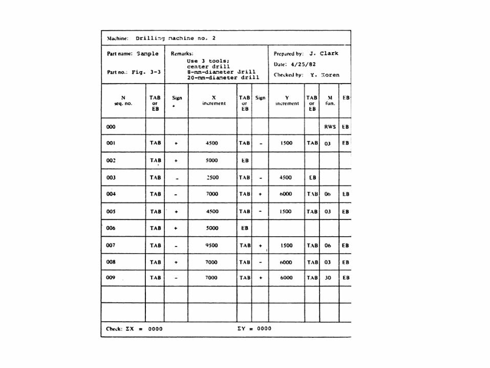
• In manual programming the data required for machining a part is written in a standard format on a special manuscript.
• The manuscript is planning chart or list of instructions which describes the operations necessary to produce the part.
• The manuscript is typed with teletype or flexowriter
• Part programming of simple parts can be performed manually with calculators.
• Its suitable for point to point machines.
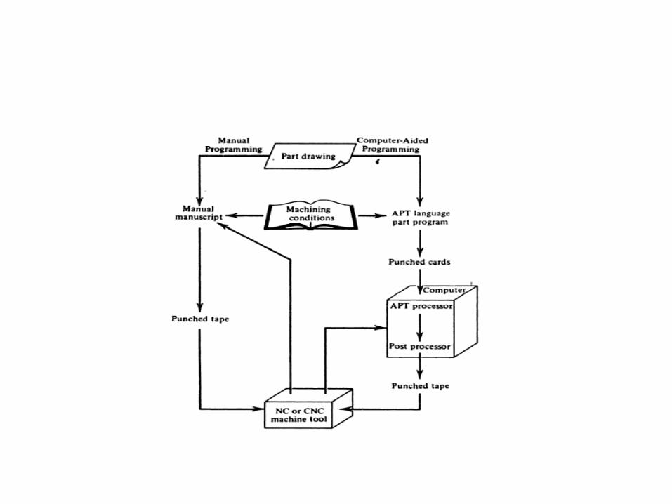
• Computers are used as an aid in NC programming by applying special purpose programming languages.
• It consist of series of statement which are punched on cards and are used as the input to the computer.
Manual Programming - Basic Concepts
• Manual tape preparation is executed by part programmers.
• Determine machining parameters and optimal sequence of operation to be performed
• Calculate tool path and write a manuscript.
• Each line is block,
• Should be in standard format eg_ RS273-A
• eg for 1 block – N102 g04 x-52000 y09100 f315 s717 t 65432 m03
(EB)
– The letter and number referred to a word
– The first letter of word is word address
– EB- end of block is not printed , but only punched. The EB indicates to the MCU that the present reading is completed and the axes of motion have to start up. When motion is accomplished the next block is read.
• Word address
– N sequential number
– G – preparatory function
– X & Y – dimensional word
– F – federate code
– S – spindle speed code
– T – tool code
– M - Miscellaneous function
• Tab sequential format, a tab character is inserted between two words in the block.
• The + sign dimension words may be ignored in most systems, where no sign means that a positive coordinate or positive increment would be used.
• RWS rewind stop code – usually placed as the first character on the tape. This code stops the tape reader when it is automatically rewinding while executing the m30 function.
Tape Format
• Perforated tape as input medium
• Electronic Industry Alliance (EIA) has prepared standard RS-273A ,RS 274-B (may 1967)
• Each line of the manuscript is equivalent to one block.
Sequence number - n
• Sequence number word n consist of three digits.
• First in block
• The major purpose is to identify specific machining operations through the block number.
• When tape is read, each sequence number is displayed at the operator console while the block commands are performed.
• Operator can compare the actual performance with the programmed commnds.
Preparatory function- g
• Preparatory function- g consist of two digit.
• Preparatory functions are used to set up the mode in which the rest of the operation is to be executed.
• G codes
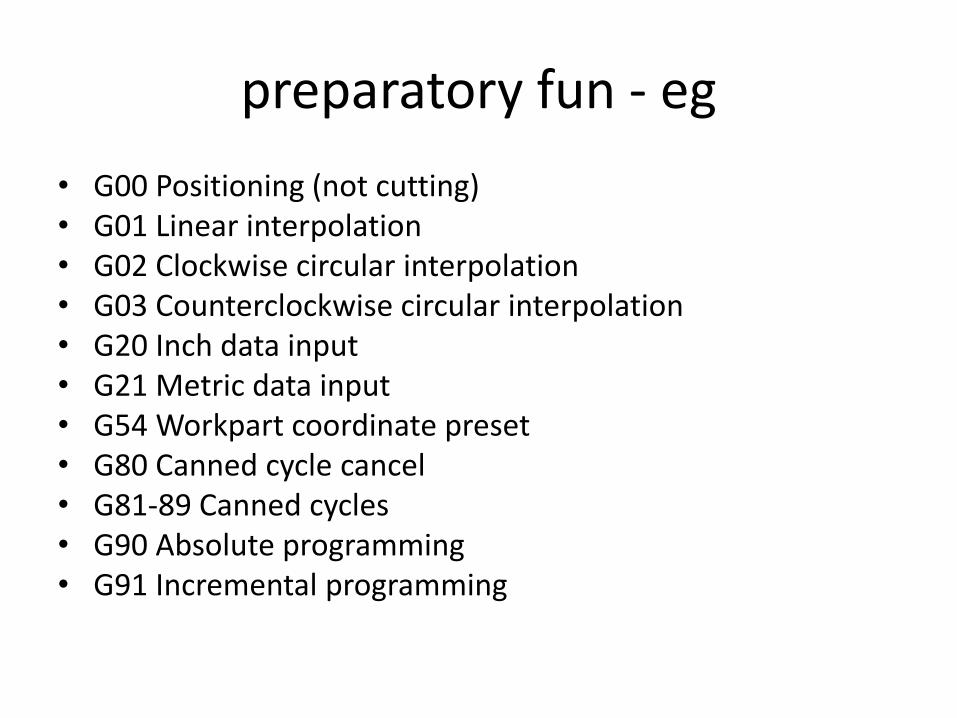
preparatory fun - eg
• G00 Positioning (not cutting)• G01 Linear interpolation• G02 Clockwise circular interpolation• G03 Counterclockwise circular interpolation• G20 Inch data input• G21 Metric data input• G54 Workpart coordinate preset• G80 Canned cycle cancel• G81-89 Canned cycles• G90 Absolute programming• G91 Incremental programming
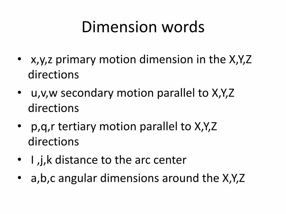
Dimension words
• x,y,z primary motion dimension in the X,Y,Z directions
• u,v,w secondary motion parallel to X,Y,Z directions
• p,q,r tertiary motion parallel to X,Y,Z directions
• I ,j,k distance to the arc center
• a,b,c angular dimensions around the X,Y,Z
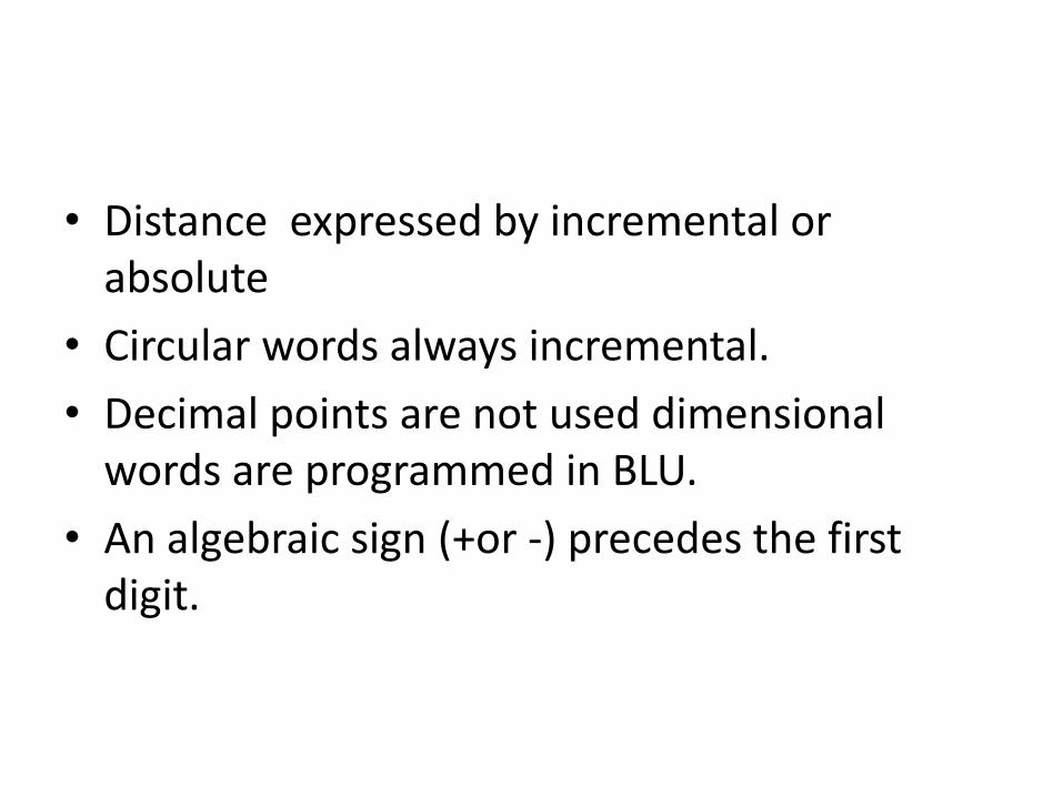
• Distance expressed by incremental or absolute
• Circular words always incremental.
• Decimal points are not used dimensional words are programmed in BLU.
• An algebraic sign (+or -) precedes the first digit.
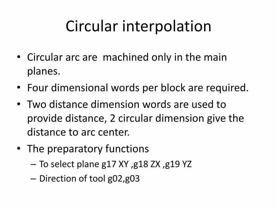
Circular interpolation
• Circular arc are machined only in the main planes.
• Four dimensional words per block are required.
• Two distance dimension words are used to provide distance, 2 circular dimension give the distance to arc center.
• The preparatory functions
– To select plane g17 XY ,g18 ZX ,g19 YZ
– Direction of tool g02,g03
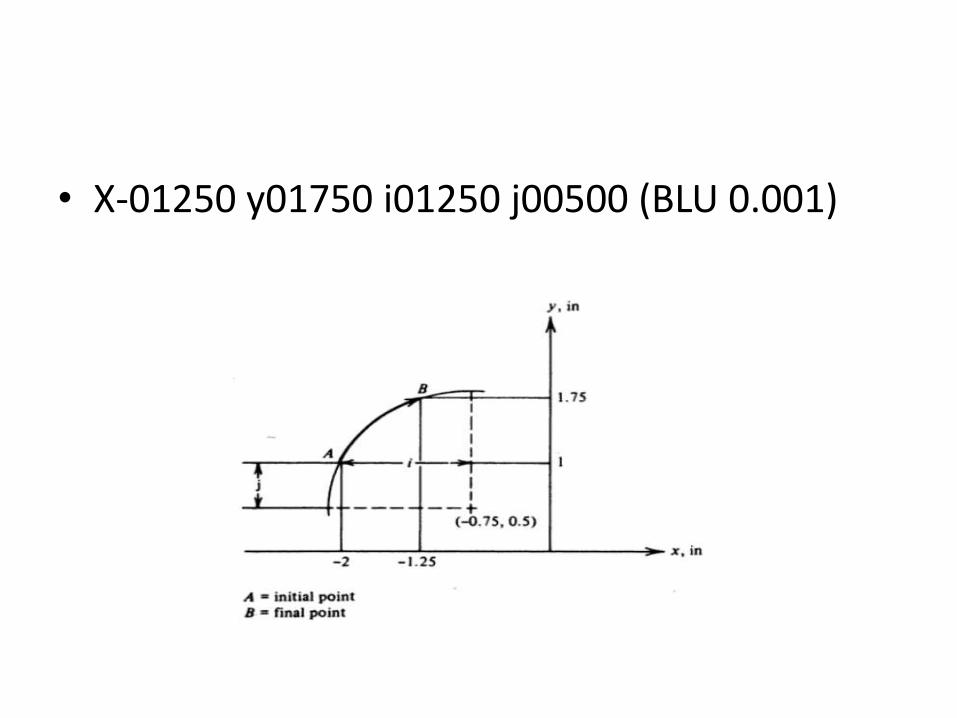
• X-01250 y01750 i01250 j00500 (BLU 0.001)
Feed word f
• The f word is generally used in contouring or straight-out systems.
• Constant maximum feedrate for point to point
Expressed asinches per minute,millimeter per minute rather than inches per revolution
Spindle speed word s
• The spindle speed word is programmed in revolution per minute and is expressed by a three digit coded number .
• Speed is rounded to 2 digit accuracy, (2nd & 3rd
digit)
• Speed is written in the form of biggest decimal fraction multiplied by the power of 10.
• First digit code has value of 3 greater than power of 10 ( power + 3)
• 1645 rpm
• Rounded to 1600
• 0.16 X 10 ^ 4
• 716
Tool word t
• Tool word may consist of a max of five digits in a coded number.
• The tool is automatically selected by the automatic tool changer when its code number is programmed in a block
Miscellaneous function m
• Consist of two digit
• It contains auxiliary information
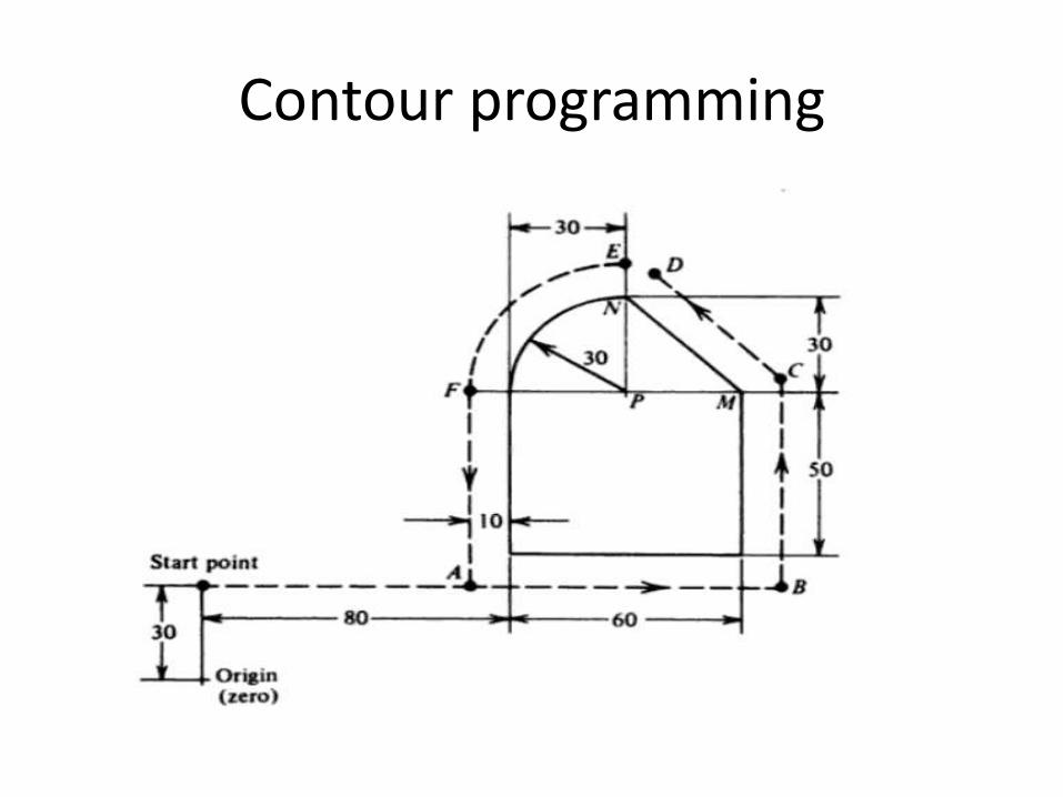
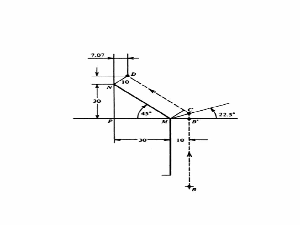
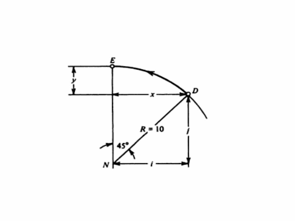
Contour programming
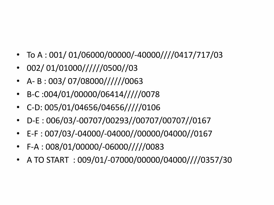
• To A : 001/ 01/06000/00000/-40000////0417/717/03
• 002/ 01/01000//////0500//03
• A- B : 003/ 07/08000//////0063
• B-C :004/01/00000/06414/////0078
• C-D: 005/01/04656/04656/////0106
• D-E : 006/03/-00707/00293//00707/00707//0167
• E-F : 007/03/-04000/-04000//00000/04000//0167
• F-A : 008/01/00000/-06000/////0083
• A TO START : 009/01/-07000/00000/04000////0357/30
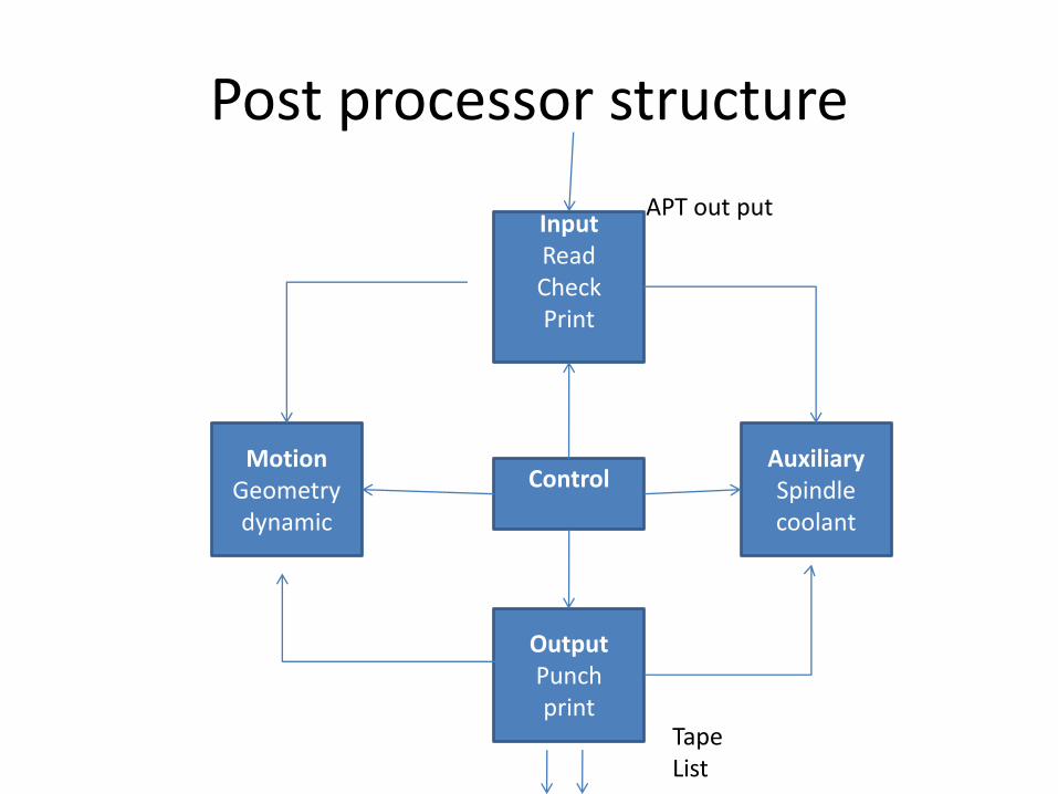
Post processor structure
InputReadCheckPrint
AuxiliarySpindlecoolant
MotionGeometrydynamic
OutputPunchprint
Control
APT out put
TapeList
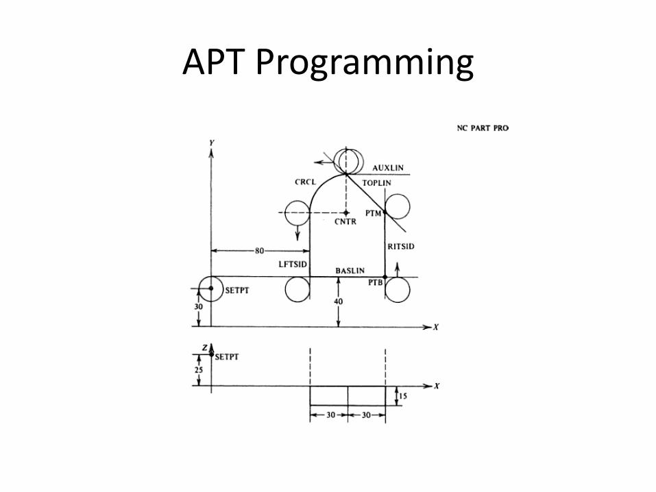
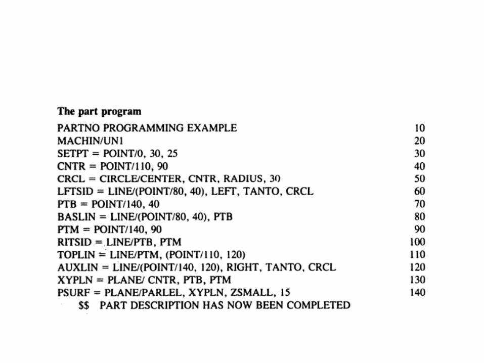
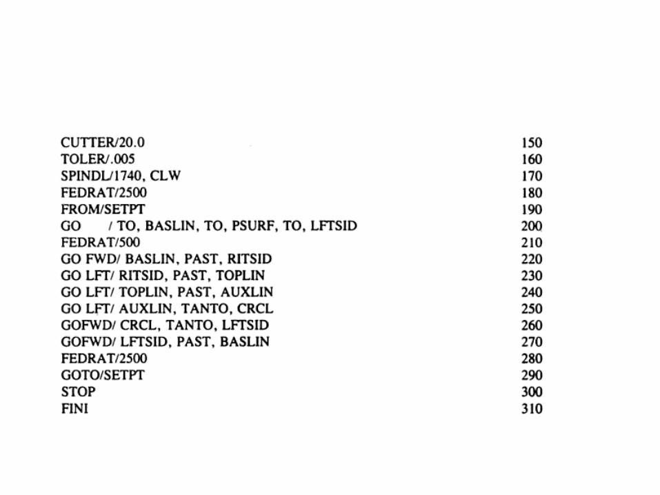
APT Programming