Embed Size (px)
Citation preview
MechatronicsModule 2
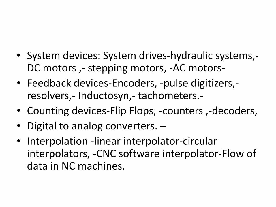
• System devices: System drives-hydraulic systems,-DC motors ,- stepping motors, -AC motors-
• Feedback devices-Encoders, -pulse digitizers,-resolvers,- Inductosyn,- tachometers.-
• Counting devices-Flip Flops, -counters ,-decoders,
• Digital to analog converters. –
• Interpolation -linear interpolator-circular interpolators, -CNC software interpolator-Flow of data in NC machines.

HYDRAULIC SYSTEMS
• Hydraulic systems are used extensively for driving high power machine tools and industrial robots.
• higher maximum angular acceleration than dc motors of the same peak power.
• Hydraulic systems, however, present some problems in terms of maintenance and leakage of oil from the transmission lines and the system components.
• The oil must be kept clean and protected against contamination.
• dynamic lags caused by the transmission lines and viscosity variations with oil temperature.
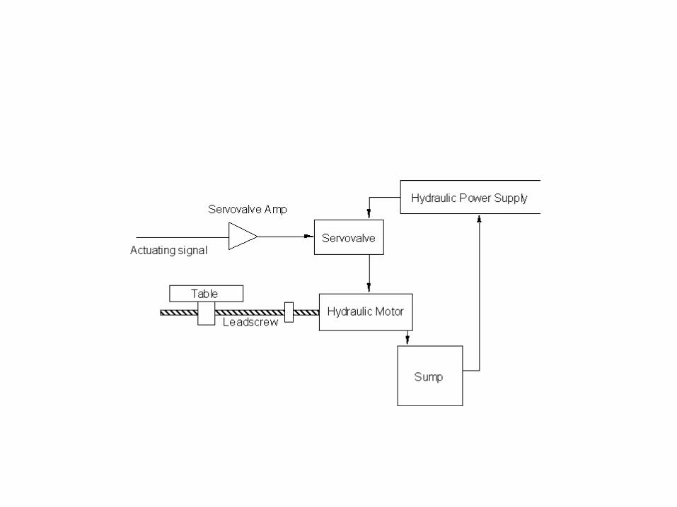
components
• a hydraulic power supply
• a servovalve for each axis of motion
• a sump
• a hydraulic motor for each axis of motion
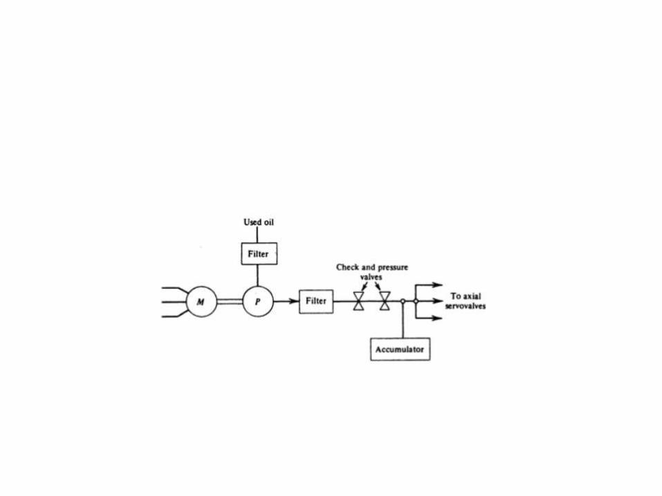
• A pump p for supplying the high pressure oil. The frequently used types are the gear pumps, and radial or axial displacement pumps.
• An electric motor M, usually a three phase induction motor,for driving the pump.
• A fine filter for protecting the servo system from any dirt or chips.
• A coarse filter, located at the input of the pump, for protecting the latter against contamination that has entered the oil supply.
• A check valve for eliminating a reverse flow from the accumulator to the pump.
• A pressure regulating valve for controlling the supply power to the servo system.
• An accumulator for storing hydraulic energy and for smoothing pulsating flow.
Servovalve
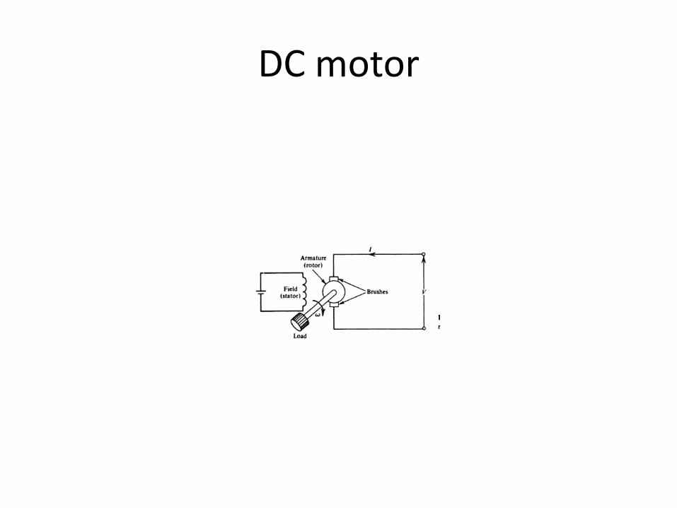
DC motor
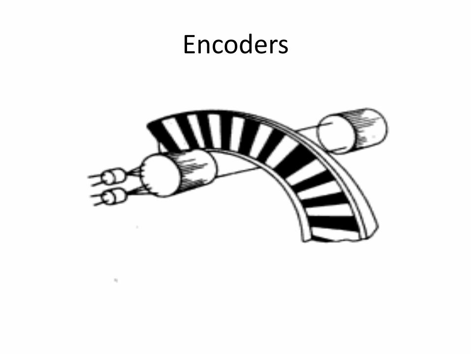
Encoders
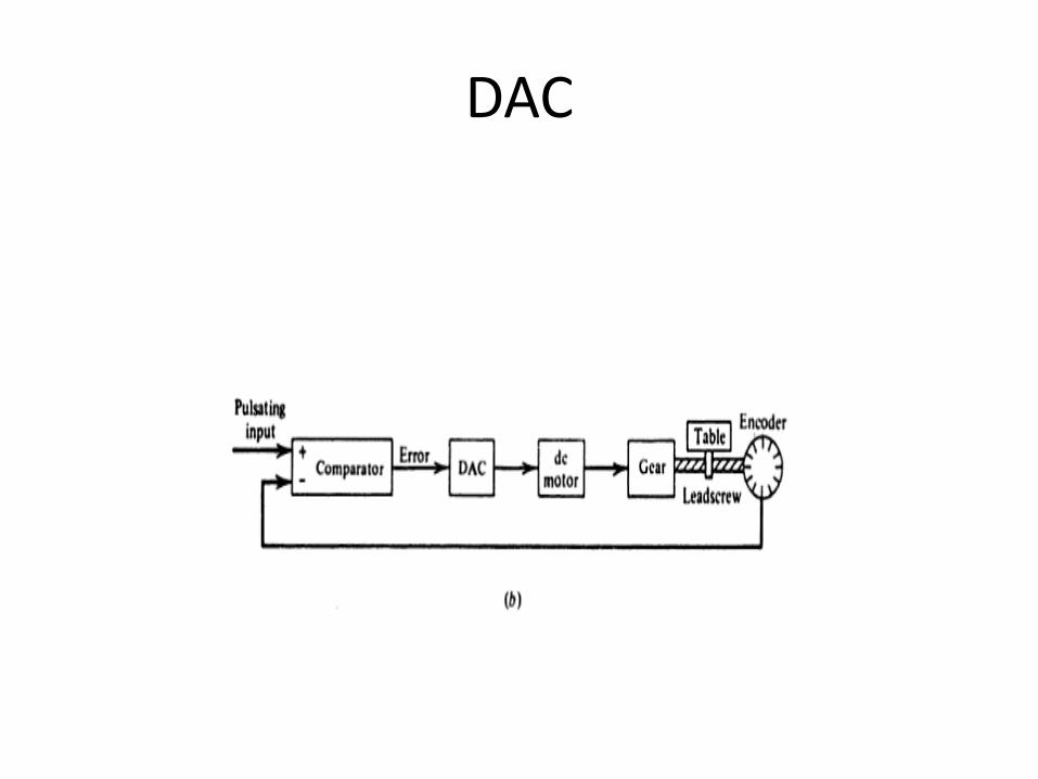
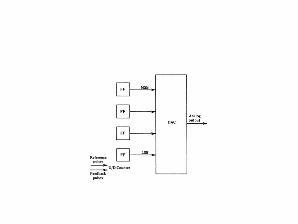
DAC
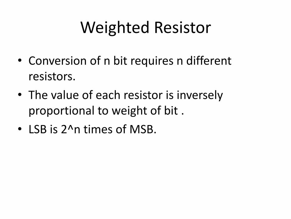
Weighted Resistor
• Conversion of n bit requires n different resistors.
• The value of each resistor is inversely proportional to weight of bit .
• LSB is 2^n times of MSB.
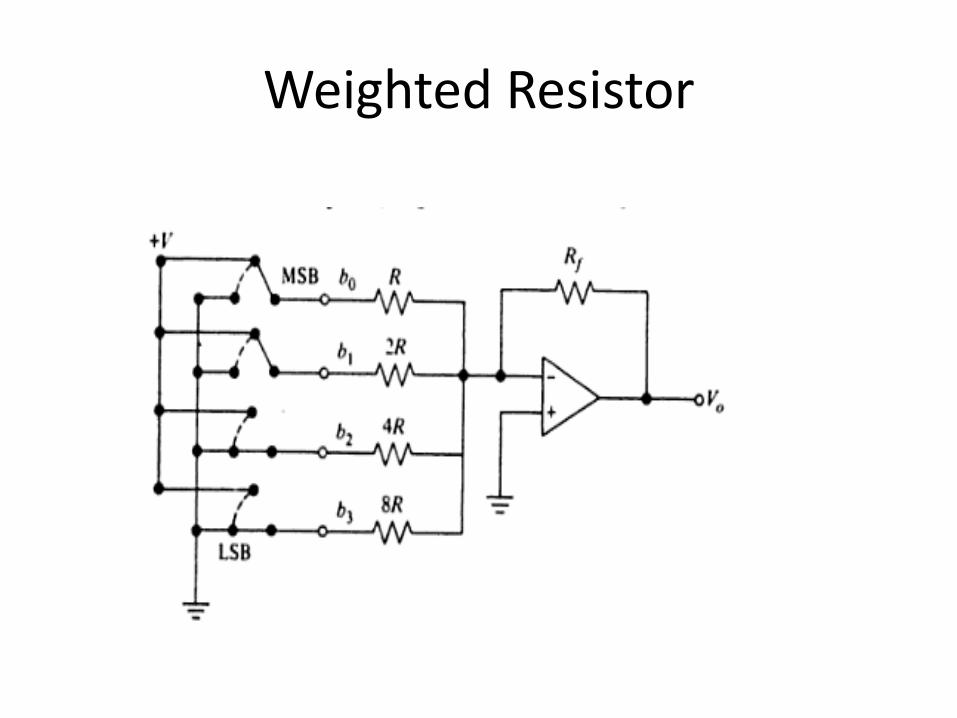
Weighted Resistor
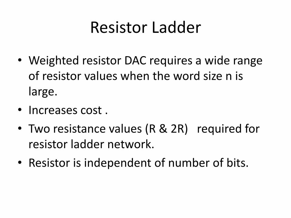
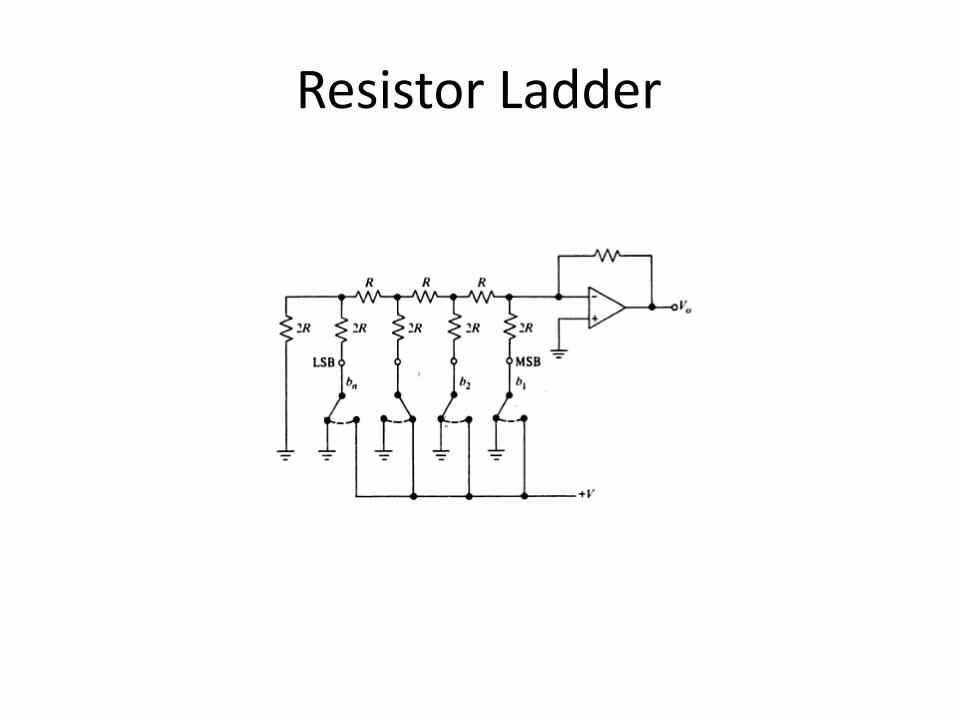
Resistor Ladder
• Weighted resistor DAC requires a wide range of resistor values when the word size n is large.
• Increases cost .
• Two resistance values (R & 2R) required for resistor ladder network.
• Resistor is independent of number of bits.
Resistor Ladder
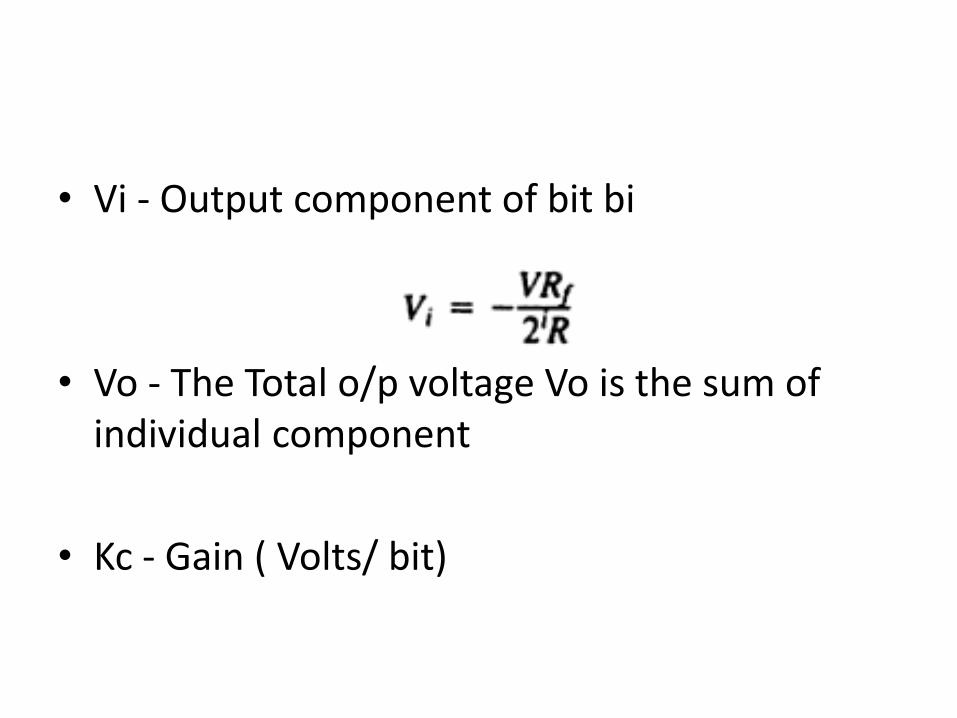
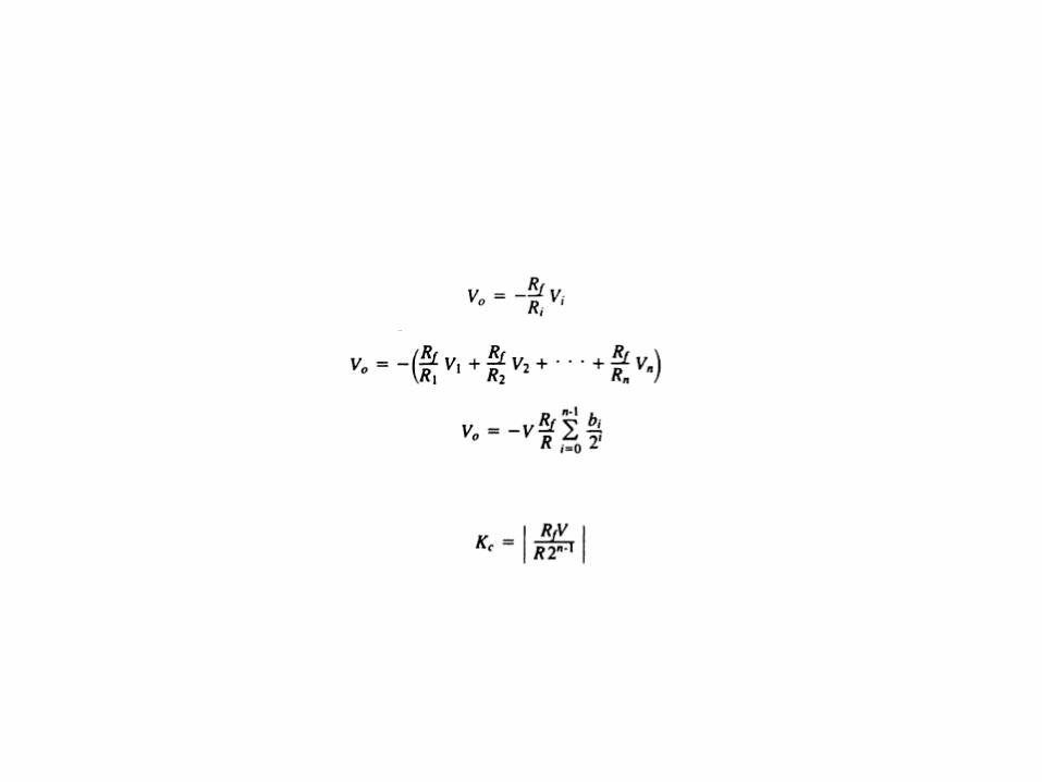
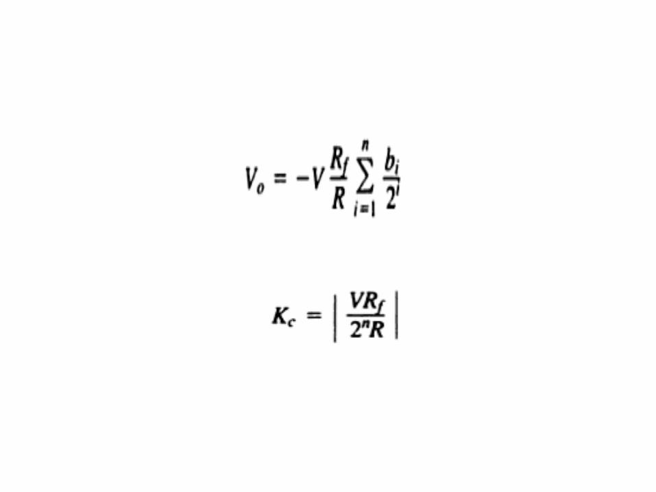
• Vi - Output component of bit bi
• Vo - The Total o/p voltage Vo is the sum of individual component
• Kc - Gain ( Volts/ bit)
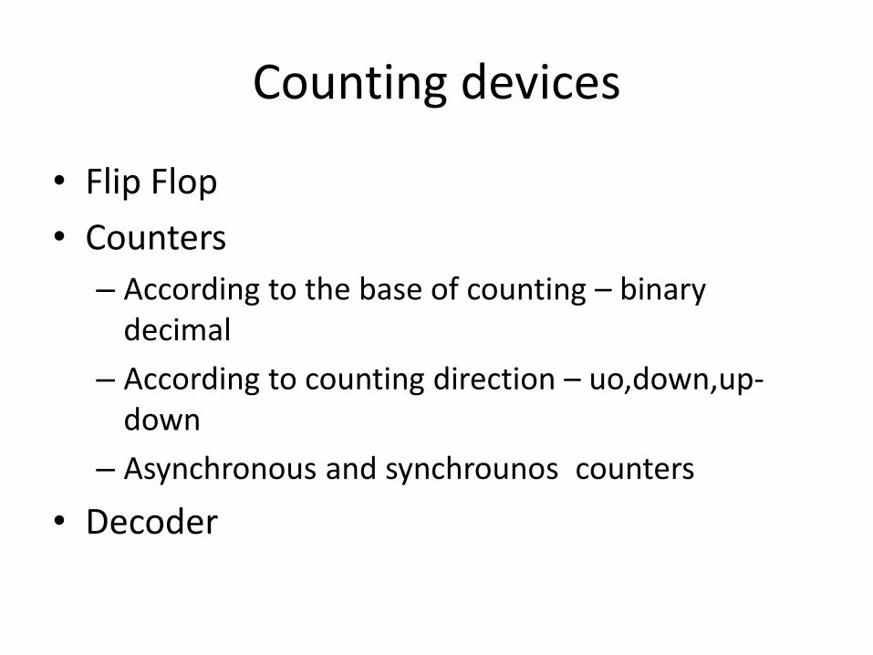
Counting devices
• Flip Flop
• Counters
– According to the base of counting – binary decimal
– According to counting direction – uo,down,up-down
– Asynchronous and synchrounos counters
• Decoder

Decoder
• Interpolators
– Linear Interpolator
– Circular interpolator
– Software interpolator

Interpolators
• The most critical and specialised activity in a CNC is axis management, which involves interpolation, servo control and drive of the motion axes.
• NC systems contain hardware interpolator which consist of digital circuits where as in CNC systems the interpolator is implemented in software
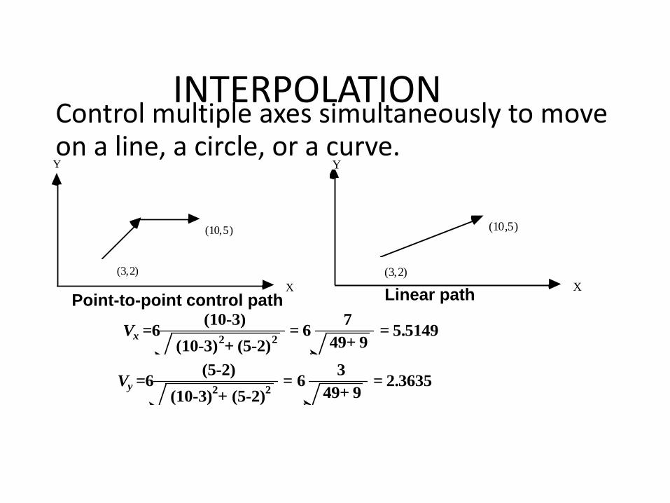
INTERPOLATIONControl multiple axes simultaneously to move on a line, a circle, or a curve.
(3,2)
(10,5)
X
Y
Point-to-point control path
(3,2)
(10,5)
X
Y
Linear path
Vy =6
(5-2)
(10-3)2+ (5-2)
2= 6
3
49+ 9= 2.3635
Vx =6
(10-3)
(10-3)2+ (5-2)
2= 6
7
49+ 9= 5.5149
INTERPOLATORS• Most common : linear and circular
• Since interpolation is right above the servo level, speed is critical, and the process must not involve excessive computation.
• Traditional NC interpolators: Digital Differential Analyzer (DDA)
• Higher order curves, such as Bezier's curve, use off-line approximation algorithms to break the curves into linear or circular segments.
DDA Integrator
• DDA is essentially an algorithm for digital integration and generates a pulse train varying in frequency.
• DIGITAL differential analyzers (DDA) are a special type of computer in which all variables are represented by digital words
• Fundamental element of DDA computer is the DDA integrator, which plays a role similar to the op amp in analog computer and forms basic block for integration.
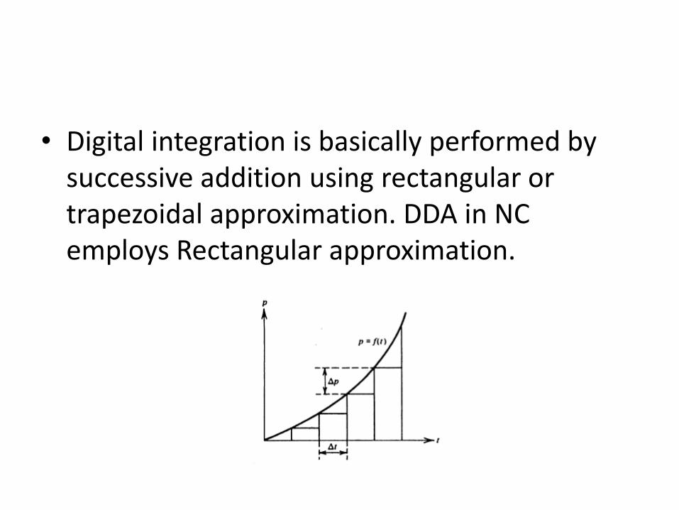
• Digital integration is basically performed by successive addition using rectangular or trapezoidal approximation. DDA in NC employs Rectangular approximation.
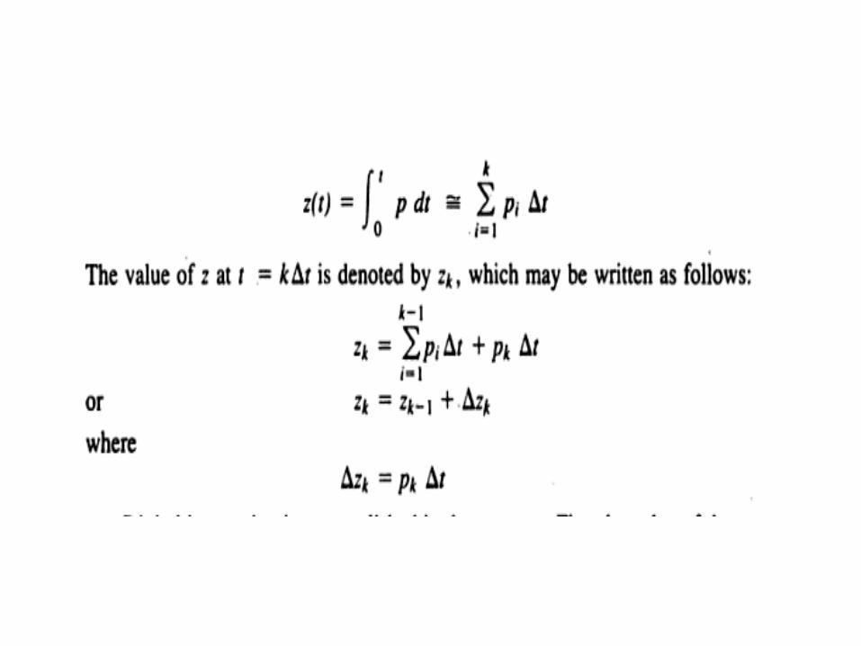

Digital Integration Steps
• 1- value of ordinate pk is computed by adding the increment ∆pk to , or subtracting it from preceding ordinate.Pk=pk-1 ± ∆pk
2. Integration increment ∆z is calculated
∆zk=pk *∆t
3. It is added to the previous z , ∆zk= ∆zk-1 + ∆zk
DDA integrator operates in an iterative mode at a frequency f provided by an external clock,
f=1 / ∆t
• Values ∆p and ∆z must be either 1 or 0.
• The DDA integrator operates cyclically at a frequency f provided by an external clock. At each iteration the variable p is added to the register q so that,
• qk= qk-1 + pk
• At intervals this addition would generate an overflow bit (∆z) , which is fed as the output reference pulse.
• The higher the value of p the higher would be the frequency of generation of an overflow and a reference pulse. Thus the rate of generation of the reference pulse would be proportional to the value of p.
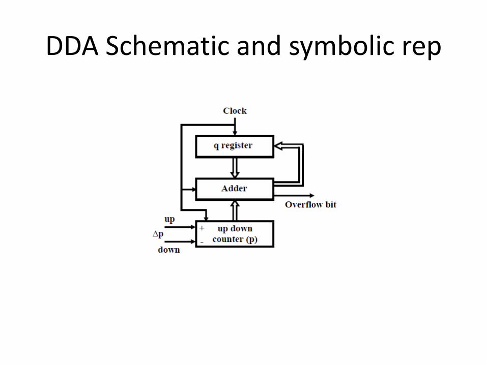
DDA Schematic and symbolic rep
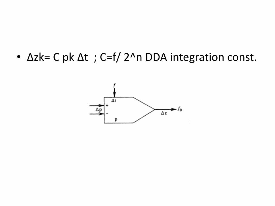
• ∆zk= C pk ∆t ; C=f/ 2^n DDA integration const.

DDA Hardware Interpolator
• In contouring systems the machining path is usually constructed from a combination of linear and circular segments.
• It is only necessary to specify the coordinates of the initial and final points of each segment, and the feed rate.
• The operation of producing the required shape based on this information is termed interpolationand the corresponding unit is the interpolator.
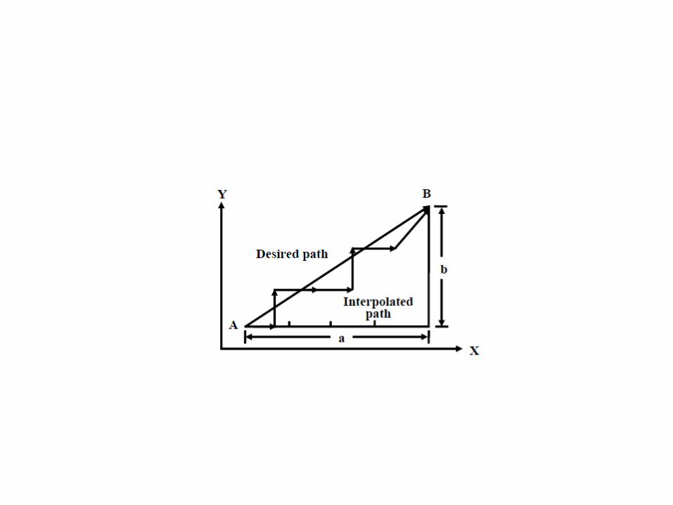
Linear Interpolation
• The ability to control the movement along a straight line between given initial and final coordinates is termed linear interpolation.
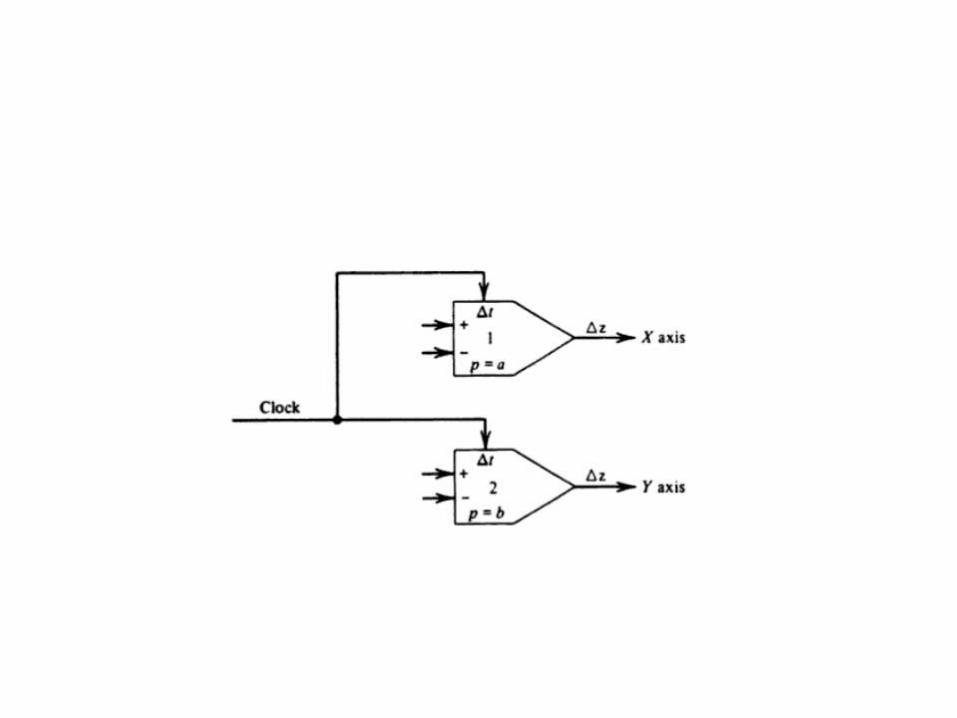
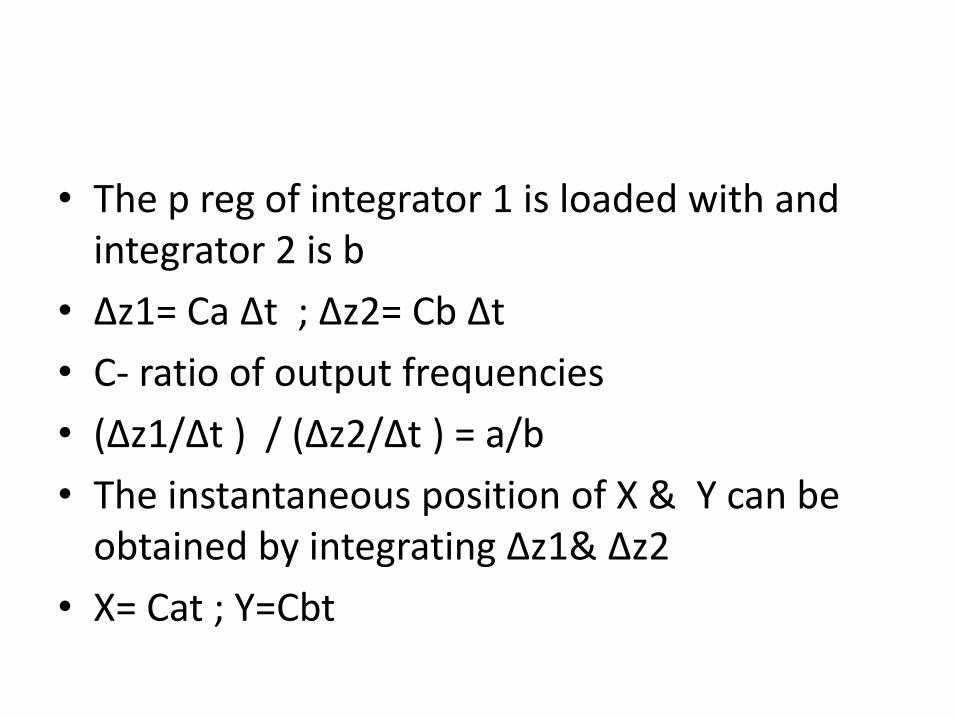
• The p reg of integrator 1 is loaded with and integrator 2 is b
• ∆z1= Ca ∆t ; ∆z2= Cb ∆t
• C- ratio of output frequencies
• (∆z1/∆t ) / (∆z2/∆t ) = a/b
• The instantaneous position of X & Y can be obtained by integrating ∆z1& ∆z2
• X= Cat ; Y=Cbt
• The ability to control the movement along a straightline between given initial and final coordinates istermed linear interpolation.
• A 2-D linear interpolator supplies velocity commands,in pulses per second, simultaneously to two machineaxes, and adjusts the ratio between the pulsefrequencies
• Movement along each axis takes place by 1 BLU forevery reference pulse along the axis. The interpolatortherefore has to provide pulses to each axis at definiterates, a and b pulses per second, along X and y axesrespectively) with respect to time.
• A common clock controls both the integrators.
• The output pulses actuate stepping motors inopen-loop systems, where each pulse causes asingle step motion, or can be fed as reference toclosed-loop systems.
• In addition to maintaining the proper velocityratio between the two axes, a desired velocityalong the path need also be maintained. This isachieved by controlling the clock frequency of thefirst two DDAs.
Circular Interpolator
• The circular interpolator eliminates the need to define many points along a circular arc.
• Center coordinate, initial point, final point, radius are required.
• For producing a circular arc the following path eqn must be satisfied
• (X-R)²+Y²=R² , R- radius
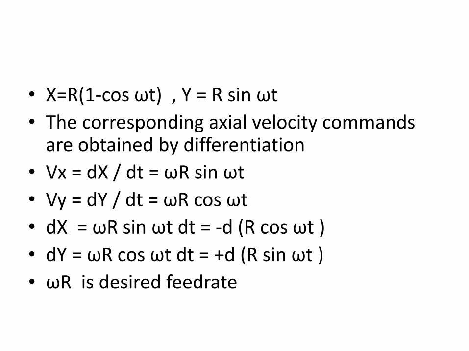
• X=R(1-cos ωt) , Y = R sin ωt
• The corresponding axial velocity commands are obtained by differentiation
• Vx = dX / dt = ωR sin ωt
• Vy = dY / dt = ωR cos ωt
• dX = ωR sin ωt dt = -d (R cos ωt )
• dY = ωR cos ωt dt = +d (R sin ωt )
• ωR is desired feedrate
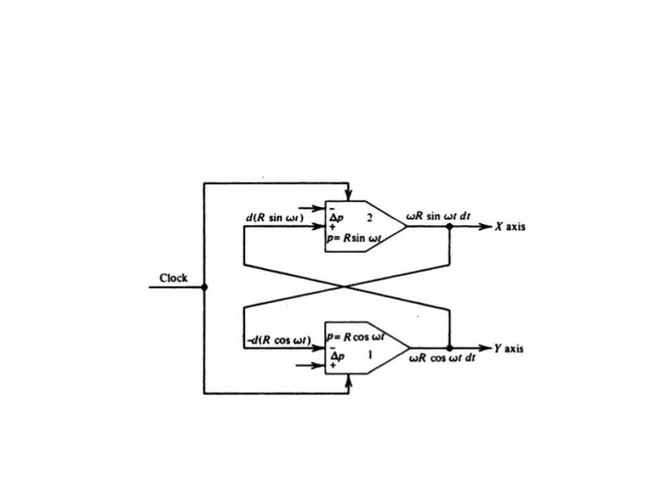
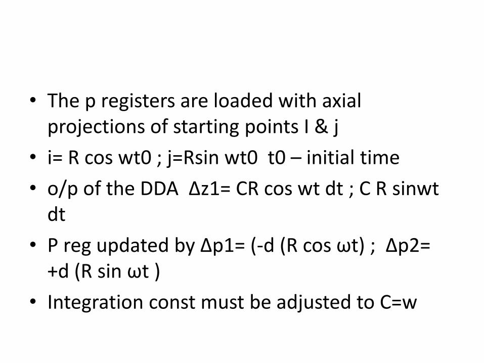
• The p registers are loaded with axial projections of starting points I & j
• i= R cos wt0 ; j=Rsin wt0 t0 – initial time
• o/p of the DDA ∆z1= CR cos wt dt ; C R sinwtdt
• P reg updated by ∆p1= (-d (R cos ωt) ; ∆p2=+d (R sin ωt )
• Integration const must be adjusted to C=w
Circular interpolator operation
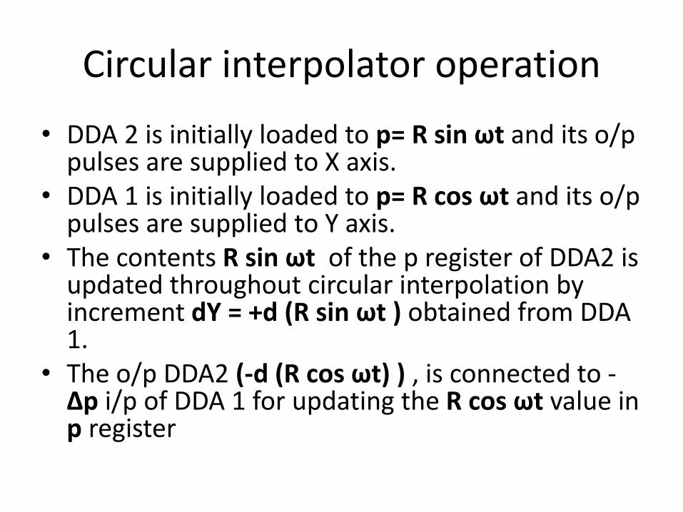
• DDA 2 is initially loaded to p= R sin ωt and its o/p pulses are supplied to X axis.
• DDA 1 is initially loaded to p= R cos ωt and its o/p pulses are supplied to Y axis.
• The contents R sin ωt of the p register of DDA2 is updated throughout circular interpolation by increment dY = +d (R sin ωt ) obtained from DDA 1.
• The o/p DDA2 (-d (R cos ωt) ) , is connected to -∆p i/p of DDA 1 for updating the R cos ωt value in p register
CNC Software Interpolator
• Interpolation carried out using a computer program instead of a logic arithmetic hardware
• CNC Classification according to Interpotation
– Reference pulse
– Reference word / sampled data systems.
• Both will generate reference signal (pulse or binary word)
Reference pulse system
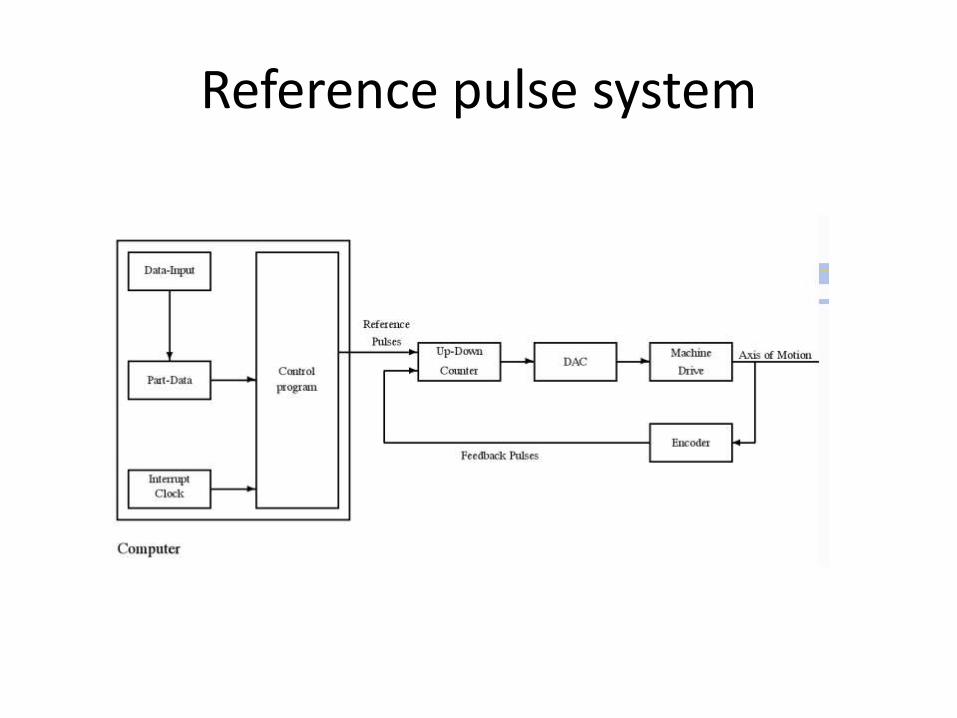
• The hardware produces a sequence of reference pulses for axis of motion .
• Each pulse generating a motion of one BLU.• The accumulated number of pulses represents
position, and the pulse frequency is proportionalto the axis velocity.
• These pulses can either actuate a stepping motorin an open loop system, or be fed as a referenceto a closed-loop system.
• Reference-pulse interpolators execute cyclicallywith a clock.
Reference pulse system
• Reference pulse interpolators are preferably written in assembly
• Floating point technique should be avoided.
• The max axis velocity is proportional to the max attainable frequency, which in turn , depends on the execution time of interpolator algorithm.
Reference pulse system
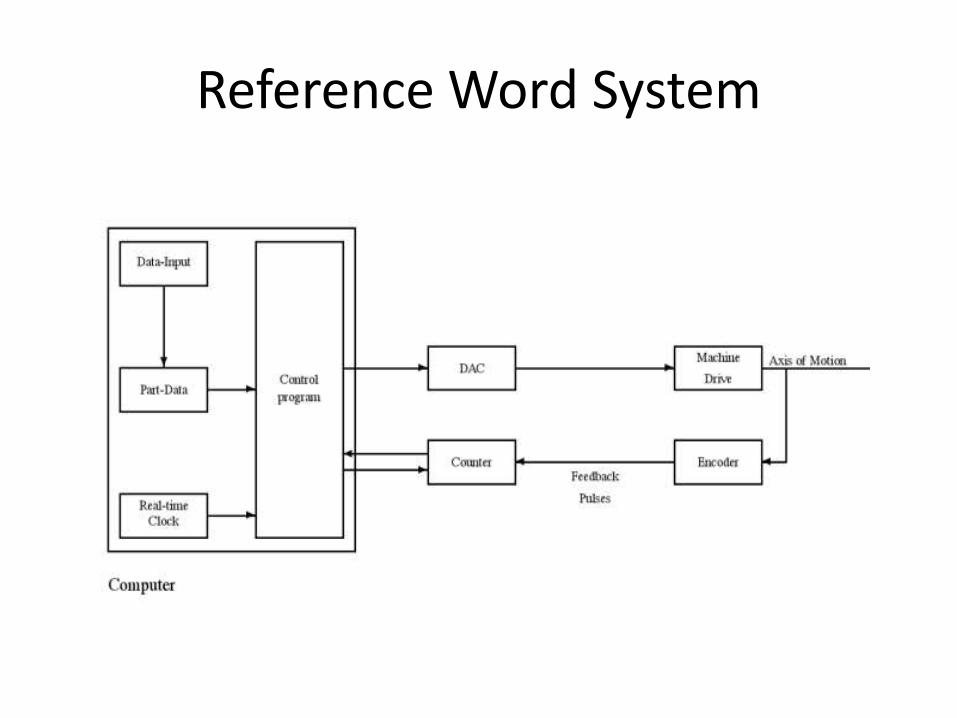
Reference Word System
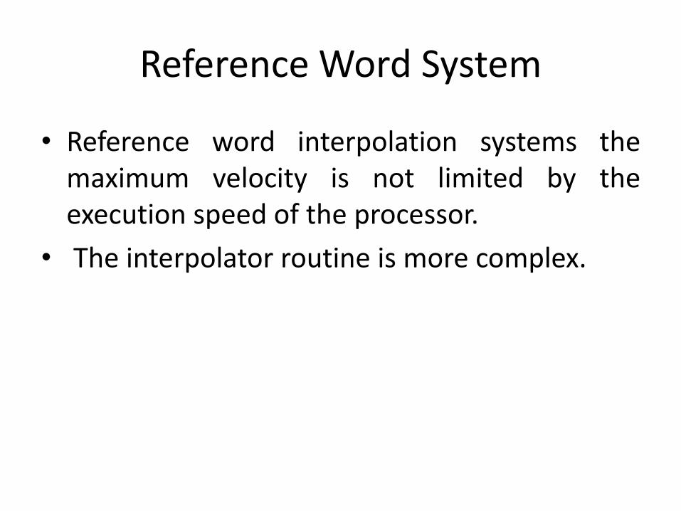
• Reference word interpolation systems themaximum velocity is not limited by theexecution speed of the processor.
• The interpolator routine is more complex.
Reference Word System
Reference Word System
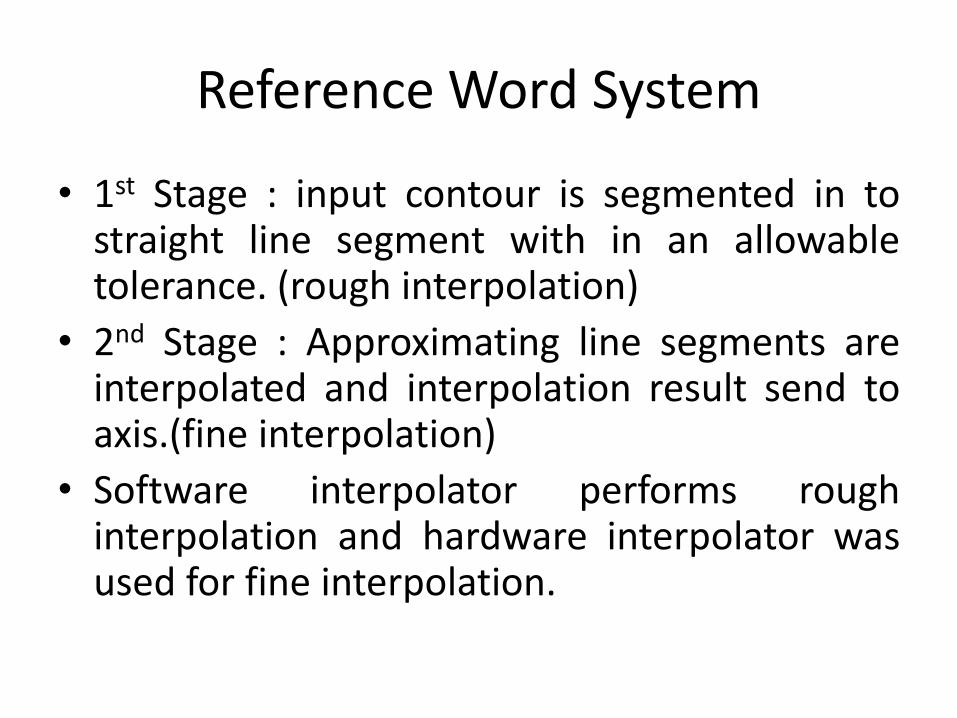
• 1st Stage : input contour is segmented in tostraight line segment with in an allowabletolerance. (rough interpolation)
• 2nd Stage : Approximating line segments areinterpolated and interpolation result send toaxis.(fine interpolation)
• Software interpolator performs roughinterpolation and hardware interpolator wasused for fine interpolation.
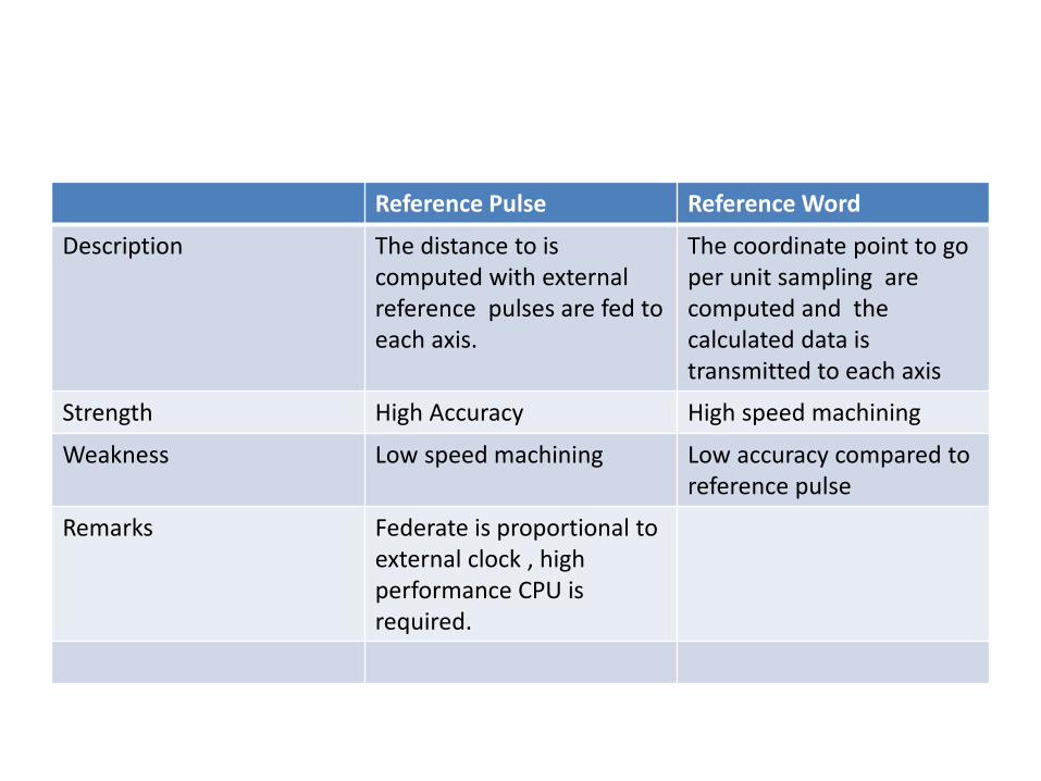
Reference Pulse Reference Word
Description The distance to is computed with external reference pulses are fed to each axis.
The coordinate point to go per unit sampling are computed and the calculated data is transmitted to each axis
Strength High Accuracy High speed machining
Weakness Low speed machining Low accuracy compared to reference pulse
Remarks Federate is proportional to external clock , high performance CPU is required.