Embed Size (px)
Citation preview
MechatronicsModule 1
• Introduction to Mechatronics.Mechatronics in manufacturing -Mechatronics in products-Scope of Mechatronics.-
• Fundamentals of numerical control-advantages of NC systems-Classification of NC systems-Point to point and contouring systems-NC and CNC – Incremental and absolute systems-Open loop and closed loop systems-
• features of NC machine tools-Fundamentals of machining-Design consideration of NC machine tools-Methods of improving machine accuracy and productivity -Special tool holders

Introduction
• The word "mechatronics" was first coined by Mr.Tetsuro Moria, a senior engineer of a Japanesecompany, Yaskawa, in 1969.
• Mechatronics may alternatively be referred to as"electromechanical systems," or as "smartproducts.“
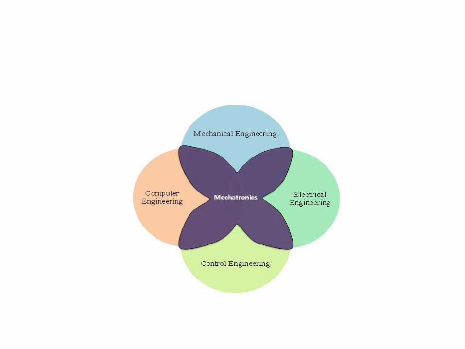
• Mechatronics is centered on mechanics,electronics and computing which, combined,make possible the generation of simpler, moreeconomical, reliable and versatile systems.

Definition
• Mechatronics is “the synergistic integration ofMechanical Engineering with Electronics andintelligent control algorithms in the designand manufacture of products process”.
• The Prime Example – Industrial Robots.
• Mechatronics can also be termed asreplacement of mechanics with electronics orenhance mechanics with electronics. Eg- FuelInjection Systems
Evolution of Mechatronics
• Primary Level : Integrates electrical signaling with mechanical action at the basic control level for e.g.fluid valves and relay switches
• Secondary Level : Integrates microelectronics into electrically controlled devices for e.g. cassette tape player.

Evolution of Mechatronics
• Tertiary Level : Incorporates advanced controlstrategy using microelectronics, microprocessorsand other application specific integrated circuitsfor e.g. microprocessor based electrical motorused for actuation purpose in robots.
• Quaternary Level : This level attempts to improvesmartness a step ahead by introducingintelligence ( artificial neural network and fuzzylogic ) and fault detection and isolation ( F.D.I.)capability into the system.

Constituents of a mechatronics system
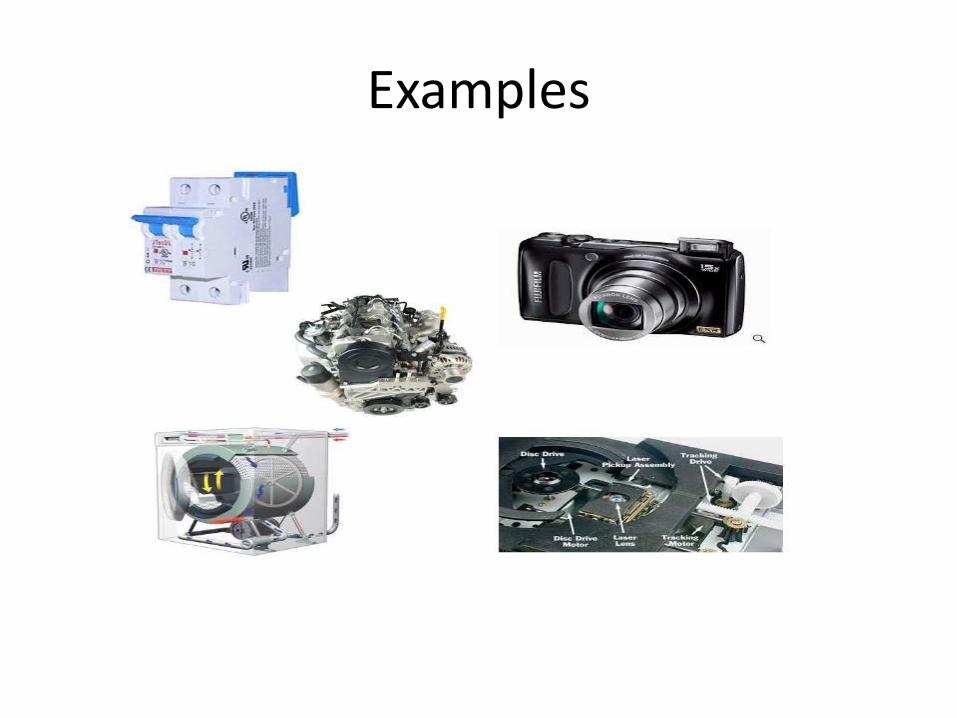
Examples
Scope
• Marketing: Signifies market research, identification ofuser needs, information analysis and formulation ofproduct specification.
• Manufacturing: Looks into process development,production planning, material handling and qualitycontrol.
• Design: The concentration is on studying fundamentalaspects of sensors, actuators, control and integrationmethods. Broadly the core of a mechatronics systemincorporates Mechanical,Electronics, Control andInformation system engineering.
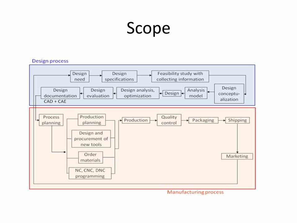
Scope

Water Fall Model

Mechatronics: products and systems in manufacturing
• Computer numerical control (CNC) machines
• Tool monitoring systems
• Industrial robots
• Advanced manufacturing systems
– a) Flexible manufacturing system (FMS)
– b) Computer integrated manufacturing (CIM)

Computer numerical control (CNC) machines
• CNC machine is the best and basic example of application of Mechatronics in manufacturing automation.
• Mechatronics based automation in these machine tools has greatly reduced the human intervention in manufacturing operation and improved the process efficiency and product quality.
• CNC is the operation of a machine tool by a series of coded instructions consisting of numbers, letters of the alphabets, and symbols which the machine control unit can understand.

Tool monitoring systems
• Tool wear is a critical factor in productivity of a machining operation.

Flexible Manufacturing Systems
• Nowadays customers are demanding a widevariety of products.
• To satisfy this demand, the manufacturers’“production” concept has moved away from“mass” to small “batch” type of production.
• Batch production offers more flexibility in productmanufacturing.
• FMS is a manufacturing cell or system consistingof one or more CNC machines, connected byautomated material handling system, and alloperated under the control of a central computer.

Benefits of an FMS
• Flexibility to change part variety • Higher productivity • Higher machine utilization • Less rejections • High product quality • Better control over production • Just-in-time manufacturing • Minimally manned operation• Easier to expand

Just-in-time manufacturing
• Just-in-time (JIT) manufacturing is aproduction model in which items are createdto meet demand, not created in surplus or inadvance of need. The purpose of JITproduction is to avoid the waste associatedwith overproduction.

Computer Integrated Manufacturing (CIM)
• Computer-integrated manufacturing (CIM) is the manufacturing approach of using computers to control the entire production process.

Industrial robots
• Parts handling
• Parts processing
• Product building
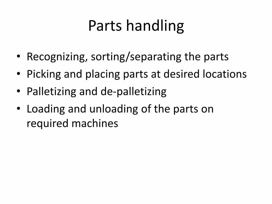
Parts handling
• Recognizing, sorting/separating the parts
• Picking and placing parts at desired locations
• Palletizing and de-palletizing
• Loading and unloading of the parts on required machines

Parts processing
• Routing • Drilling • Riveting • Arc welding • Grinding • Spray painting • Coating • Sand blasting • Gluing • Polishing
• Fundamentals of NC
• Advantages of NC
• Classification of NC
– PTP- Contour
– NC-CNC
– Incremental – absolute
– Open loop – closed loop
• Punched Card

Manufacturing Systems Evolution
• Construction of simple production machine started in 1770
• Fixed automatic mechanisms and transfer lines for mass production came along at this century
• Introduction to Numerical control NC in 1952• The logical extension of NC – CNC• Industrial robots were developed simultaneously with
CNC• First commercial robot in 1961• 1969 Mechatronics –• FMS with CAD / CAM
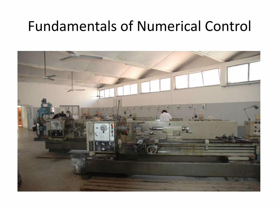
Fundamentals of Numerical Control
• Fundamentals of Numerical Control

Definition – EIAElectronics Industries Assoc.
• Numerical Control is a system in which
actions are controlled by the direct insertion of
numerical data at some point. The system
must automatically interpret at least some
portion of the data.

MACHINE UNIT
NUMERICAL
CONTROLLER
NUMERICAL
DATA
(NC CODE)
MANUFACTURING
OPERATOR
PROCESSED
PART
Drive Control
28

Types of Numerical Control
• Conventional Numerical Control (NC)
– Data is sent to the machine tool by means of
punch cards or tapes. The reader at the machine
performs no calculations or interpolations.
• Computer Numerical Control (CNC)
– The idea of computer numerical control is to
position a computer right at the machine tool.
29
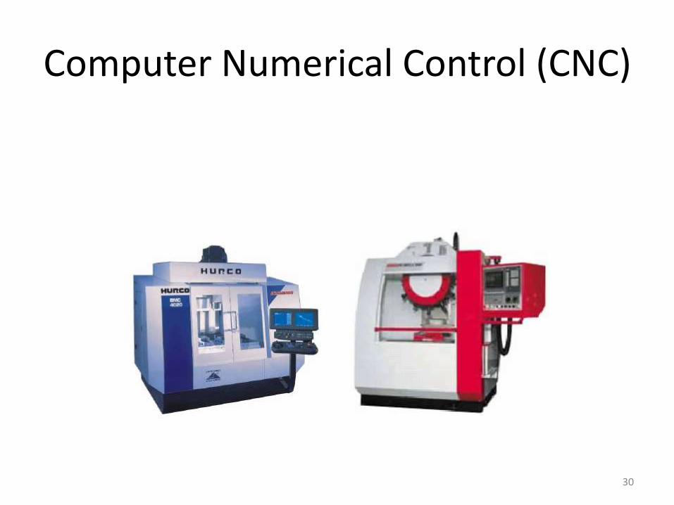
Computer Numerical Control (CNC)
30

• Part Program- Numerical data on a punched tape.
• The block contains , in coded form , all information for processing a segment of work piece like Segment length, cutting speed,
• NC replaces the manual actions of the skilled operator.

• Part Programmer V/s Skilled operator.
• APT – Automatically Programmed Tool
• BLU- Each unit corresponds to the position resolution of axes of motion referred to Basic Length Unit.
• BLU is also known as ‘increment size’ or ‘bit weight’.
•
• The part dimensions are expressed in part programs by integers
• To calculate position command in NC, the actual length is divided by the BLU value.
• To move 0.7 inch in positive X direction , with BLU =0.001, the position command is X+700

• Axis of motion – An axis in which the cutting tool moves relative to the work piece.XYZ
• Machine tools- drilling,milling,lathe
• Rotary motions also possible.

NC machine parts
• MCU
– Data Processing Unit
• To decode the information received from tape, process it, and provide data to CLU
– Control Loops Unit.
• Operated Drive attached.
• Machine tool

Advantages of NC
• First NC- 1952.
• Accuracy- Measuring Time
• 70-80 % Time wasted on measurements
• Tolerance improved.
• A Further saving of time is achieved while passingfrom one operation to another during themachining of the work space.
• Rate of production decreases in conventionalmethod

• Contour cutting in 3 D or 2D can not performed by manual operation
• Two Hand wheels required for this operation

CNC - Disadvantages
• High initial investment
• A long preparation time for each production series.
• Inflexibility of the process. Machine is planned to make a certain fixed cycle of operation. If the part configuration changed , The machine adjustment must be rebuilt or altered.
• A big stock of parts is required for the process.
• NC in Flexible Manufacturing System
• Production in low quantity
• Eg . Aircraft
• Machines should be economical.
• When a new product required , only the part program has to b chgange.

Advantages of NC
1. A Full flexibility ; a part pgm is needed for producing a new part
2. Accuracy is maintained through the full range of speeds and feeds.
3. A shorter production time4. Easy adjustment of the machine. Less time than other
manufacturing methods5. The possibility of manufacturing a part of complicated
contour.6. Need for highly skilled & Experienced labor is avoided7. The operator has free time

Disadvantages of NC
• A relatively high cost
• More complicated maintenance- Special maintenance crew is desirable.
• Highly Skilled & properly Traned part programmer is needed
•

Classification of NC
• According to type
– Point to point / contouring
• According to Structure
– NC/ CNC
• According to programmed method
– Incremental / absolute
• According to type of control loops
– Open loop / closed loop

Point to point
• Drilling machine
• Work piece is moved along axis of motion until center of hole is drilled is exactly beneath the drill
• Drill is automatically moved to the work piece, hole is drilled , and the drill moves out in a rapid traverse speed.

Contouring systems
• In countering or continuous-path systems, the tool is cutting while the axis of motion are moving.
• Eg. milling machine
•
Interpolator
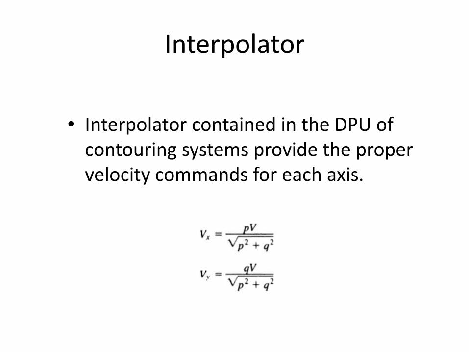
• Interpolator contained in the DPU of contouring systems provide the proper velocity commands for each axis.
Straight Cut Systems
• PTP machine equipped with milling tool.

NC & CNC
• NC- Hard ware based
• CNC- software based
• The digital control in NC employs voltage pulse.
• 1 pulse = BLU (NC)
• Pulses to actuate motors.
– Stepper- open loop
– DC motor – closed loop

• 1 bit = BLU (CNC)
• Simplest hardware configurations – emulates hardware based NC and transmit output pulse.
• 1 bit =1 pulse =BLU
• The main difference in the operation between NC and CNC is in the way that the punched tape is read.– NC – read 1 block and cut
– CNC – store complete data , stored in memory before cutting starts.

Incremental / Absolute

Absolute - Advantages
• With an incremental system , each time the work is interrupted the operator must restart the part pgm and repeat the entire operation
• Dimensional data can change at any time.
• One reference point

Incremental - Advantages
• Inspection of the part pgm is easy. Sum ofposition commands must be zero
• The performance of the incremental system canbe checked by a closed-loop tape. This is adiagnostic punched tape which test the variousoperations and performance of the NC Machine
• Mirror image programming is facilitated withincremental systems. The sign of thecorresponding position commands is changedfrom + to - . No new calculation required for theposition

Open Loop / Closed loop

Topics
• Fundamentals of machining
• Design Consideration of NC Machine Tools
• Method to increase accuracy and productivity
• Special Tool Holders

~
Servo Controller
Counter Comparator
Encoder A/C Motor
Input (converted from analog to digital value)
TableLeadscrew
Fundamentals of machining
• Machining is the manufacturing process in which the size, shape or surface properties of a part are changed by removing excess materiel.
• High Accuracy and good surface finish are required.
Basic machine Tool
• Lathe or turning machine
• Drilling or boring machine
• Milling machine
• Shaper or planer
• Grinder

Material Removal
• Chemical – Electro Chemical machining(ECM)
• Electrical – electrical discharge machining (EDM)
• Thermal – laser beam machining.

Metal removal rate
• Cutting speed
• Size of cut
– Feed
– depth

Cutting Speed (v)
• Cutting speed defined as the relative velocity between cutting tool and work materiel.
• Unit- feet per minute , meters per minute
• NC- Spindle speed (angular velocity of work piece , rev/min)
• Spindle speed N= 12v/∏D
• D average diameter in inches


Depth of cut (d)
• Defined as the distance the cutting tool projects below the original surface of the work
• Expressed in thousandths in an inch or in millimeter

Feed (f)
• Defined as the relative lateral movement between tool and work piece during the machine operation.
• Inches per revolution , mm per revolution
• Milling operation- length units per tooth –inches per tooth, mm per tooth
• NC machine- length per minute- feed rate.
• Feed rate – feed X spindle speed

Metal removal rate
• The product of proper speed feed, and depth of cut determines the metal removal rate(MRR)
• Volume – units per minute.
• Productivity of the machine during cutting is proportional to MRSR
Design Consideration of NC Tools
• Better Accuracy to increase productivity
• Design Control techniques and computers have undoubtedly contributed towards achieving these goals.
• The term accuracy is often mistakenly interchanged with the terms resolution and repeatability.
• Resolution mainly dependent on position feedback sensor

• Resolution– Programming Resolution – smallest allowable
position increment (BLU)
– Control Resolution- smallest change in position that the feedback device can sense.
– Eg assume that an optical encoder which emits 1000 voltage pulses per revolution of shaft is directly attached to 10 mm pitch lead screw . This encoder will emits one pulse for each 0.01 mm. the unit 0.01 is control resolution
• To obtain the best systems accuracy programming resolution is equal to control resolution(System resolution).
• Accuracy also depends on computer control algorithms, system resolution and machine inaccuracies.
• System in accuracy due to resolution is usually considered to be ½ BLU. Since displacement smaller than 1 BLU can be neither programmed nor measured .

• System accuracy = ½ BLU + machine accuracy
• The machine designer tries to ensure that accumulated effect of all in accuracies associated with machine tool will be under ½ BLU

Methods of Improving Machine Accuracy
• Tool Deflection & Chatter
• Lead screws
• Thermal Deformations

Tool Deflection & Chatter
• The force of the tool edge against the work piece in milling & turning deflects the tool and tool holder and causes dimensional error.
• This error can be removed by increasing stiffness of the construction of tool mounting

• Chatter -Vibratory response due to tool deflection
• If cutting tool deflects at one more than average, and as result a lump is left on the workpiece at the point .
• Chatter occurs as a function Of the machine structure, too, workpiece material, and cutting condition.
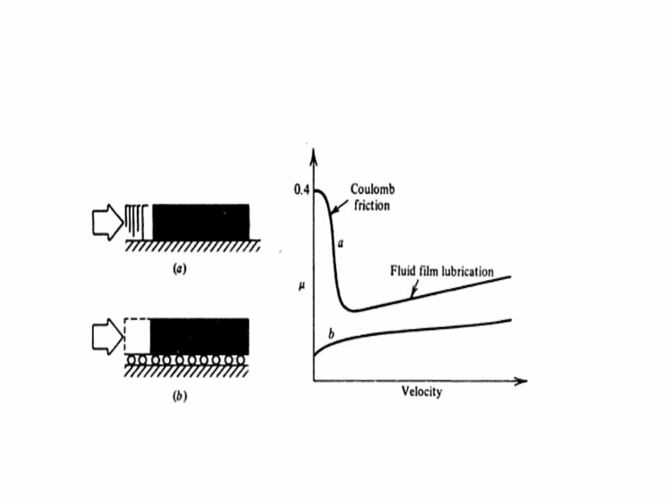
Lead screws
• In accuracies due to mechanical linkage between leadscrew and the tool.
• In order to improve the accuracy , this mechanism must be time in varient ( no heating effect) and linear ( no backlash and friction)

Thermal deformation
• Sources of heat
– Marching process
– Spindle and driving motors
– Friction of slideways & lead screws

• A temp difference of 1˚C along 1000 mm can cause an error of 0.01 mm
• Machine tool manufacture must take the thermal effects into considerations in design stage of the machine.
• It can avoid by removing hi-power motor, providing large heat removing surface, use of low friction bearings,symmetrical distribution of heat sources.

• Heat effect can not completely removed
• Precise machining are always located in an air-conditioned environment or separate room

Increasing Productivity With NC Machine
• Actual cutting time
• idle and traverse motion time
• Loading and unloading time
• Tool changing time

Special Tool Holders
• A substantial saving in time is obtained with automatic tool changing methods.
• For simple turning and drilling operations, six or eight tools may be adequate, and this restricted number would enable the use of simple turret machine.
• Turret is not regarded as an ATC
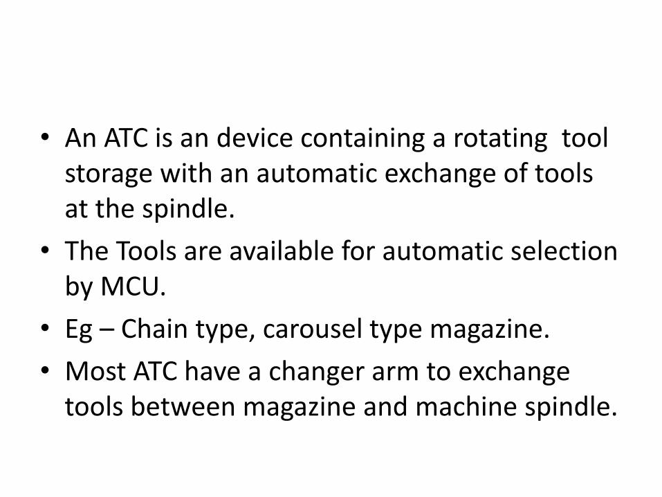
• An ATC is an device containing a rotating tool storage with an automatic exchange of tools at the spindle.
• The Tools are available for automatic selection by MCU.
• Eg – Chain type, carousel type magazine.
• Most ATC have a changer arm to exchange tools between magazine and machine spindle.

• The changer arm rotates 90 degree and engages the tools in the spindle and magazine simultaneously.
• The arm grips the tools mechanically, Move forward to remove tools from the socket.
• The changer arm continuous the rotation with the two tools to change the position of the tools by 180
• The arm retracts back to the machine column and places the selected tools in machine spindle and the used tool in spindle.
• The arm rotates an additional 90 to its rest position, while machining operation resumes.


![DIY Mechatronics[1]](https://img.pdfslide.us/doc/110x75/55cf999d550346d0339e4a92/diy-mechatronics1.jpg)


