Embed Size (px)
Citation preview
Meeting 16 – 4/15/16
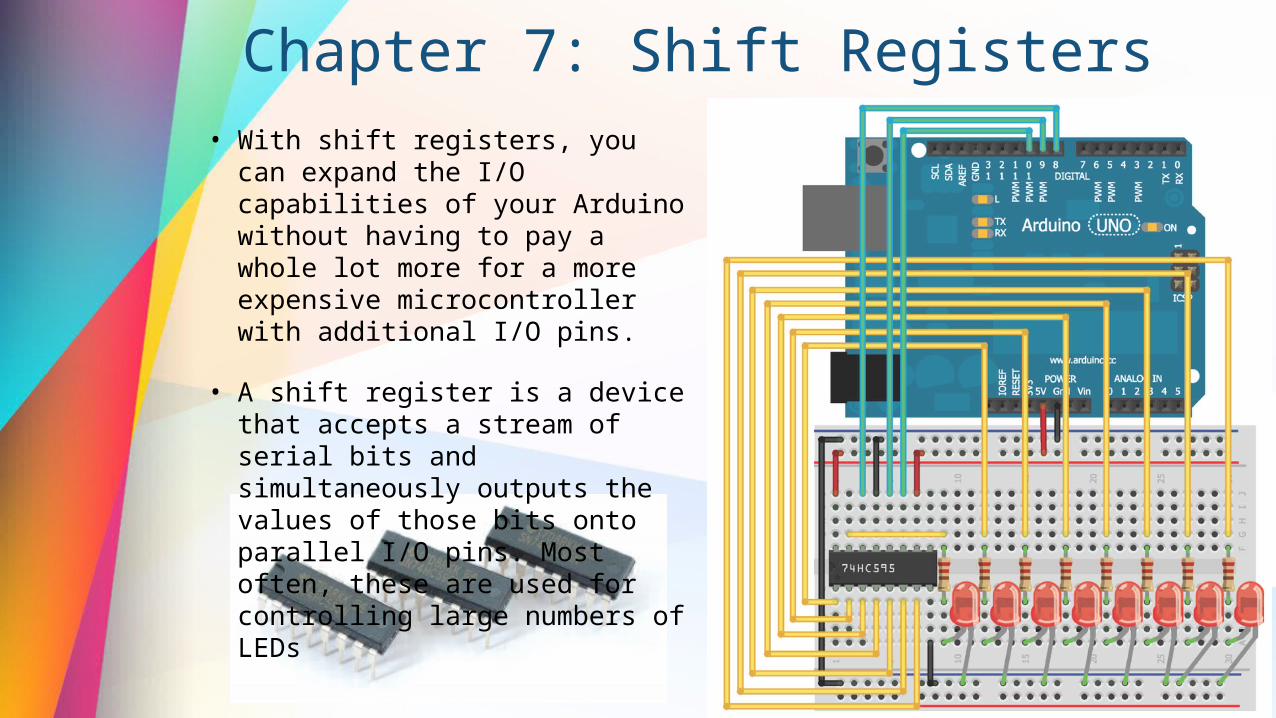
Chapter 7: Shift Registers • With shift registers, you can expand the
I/O capabilities of your Arduino without having to pay a whole lot more for a more expensive microcontroller with additional I/O pins.
• A shift register is a device that accepts a stream of serial bits and simultaneously outputs the values of those bits onto parallel I/O pins. Most often, these are used for controlling large numbers of LEDs
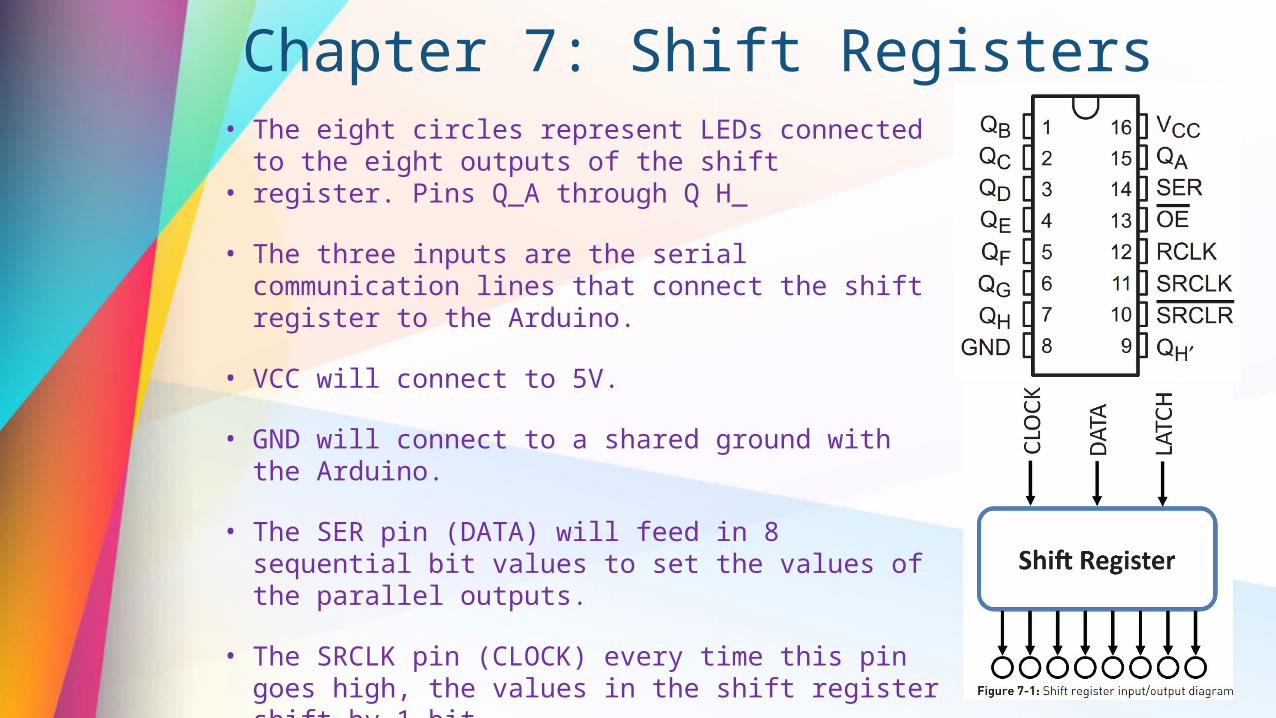
Chapter 7: Shift Registers • The eight circles represent LEDs connected to the eight outputs
of the shift• register. Pins Q_A through Q H_
• The three inputs are the serial communication lines that connect the shift register to the Arduino.
• VCC will connect to 5V.
• GND will connect to a shared ground with the Arduino.
• The SER pin (DATA) will feed in 8 sequential bit values to set the values of the parallel outputs.
• The SRCLK pin (CLOCK) every time this pin goes high, the values in the shift register shift by 1 bit.
• The RCLK pin (LATCH) allows you to sequentially shift data into the chip and have all the values show up on the parallel outputs at the same time.
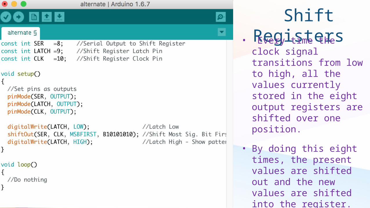
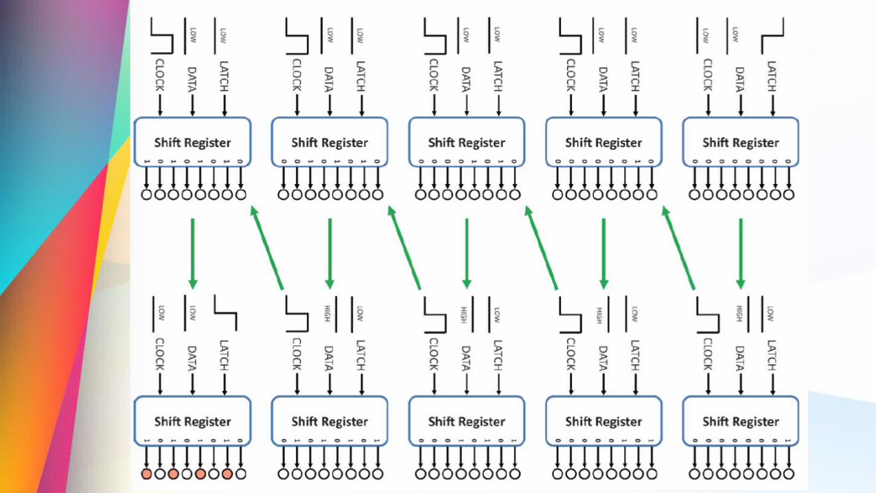
Shift Registers • Every time the clock signal
transitions from low to high, all the values currently stored in the eight output registers are shifted over one position.
• By doing this eight times, the present values are shifted out and the new values are shifted into the register.
• The LATCH pin is set high at the end of this cycle to make the newly shifted values appear on the outputs.
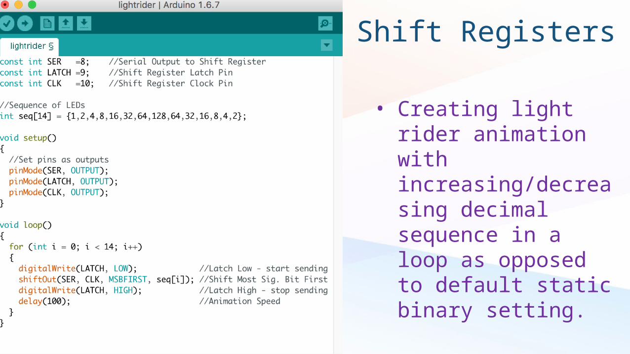
Shift Registers
• Creating light rider animation with increasing/decreasing decimal sequence in a loop as opposed to default static binary setting.
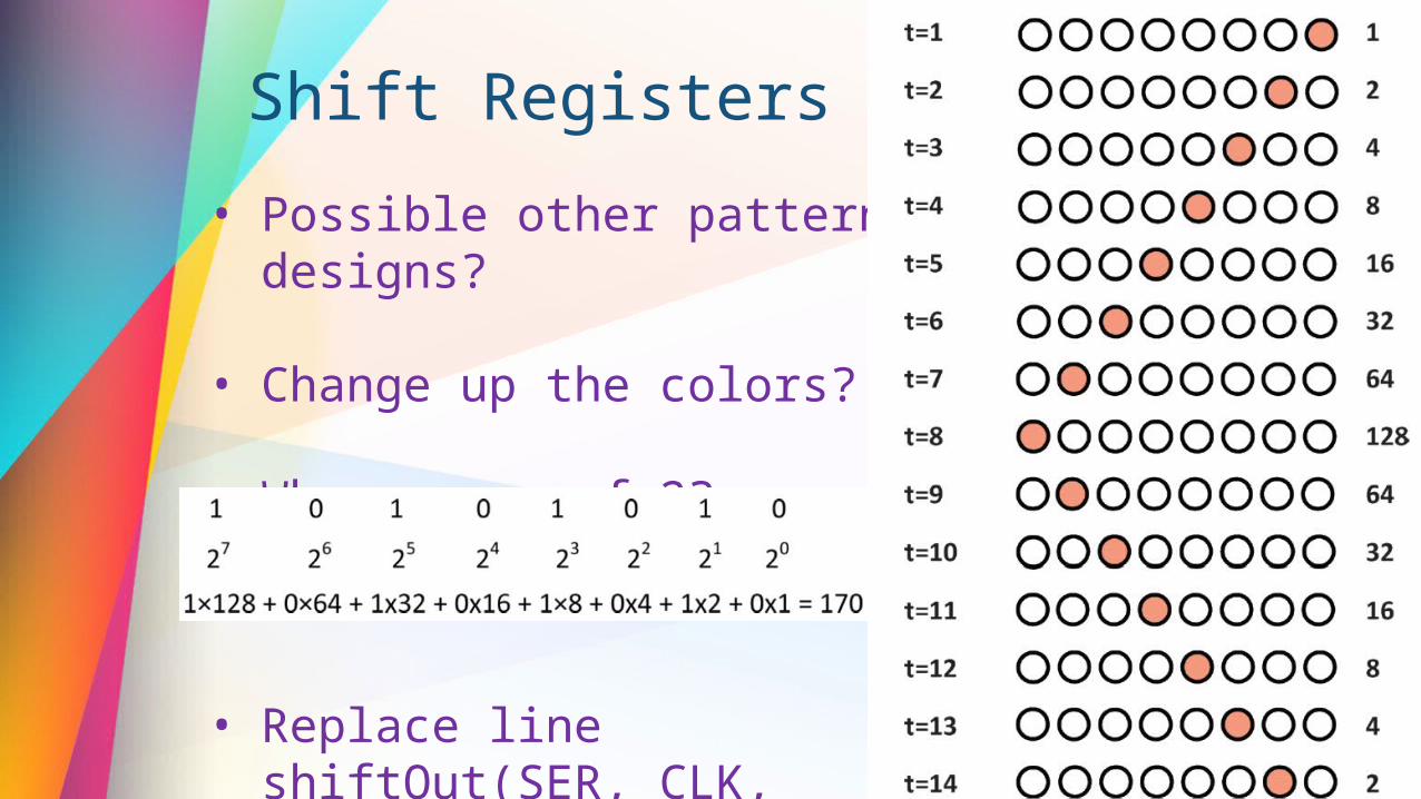
Shift Registers
• Possible other pattern designs?
• Change up the colors?
• Why powers of 2?
• Replace line shiftOut(SER, CLK, MSBFIRST, 170);

For next time... (4/22) • Read Chapter 7
• up to pg 156
• Pulse Sensor (finally!) here
• For next year...?