Embed Size (px)
Citation preview

New insights on diapirism in the Adriatic Sea: the Tremiti salt
structure (Apulia offshore, southeastern Italy)
Vincenzo Festa, Gianvito Teofilo, Marcello Tropeano, Luisa Sabato and Luigi SpallutoDipartimento di Scienze della Terra e Geoambientali - via E. Orabona 4, Universit�a degli Studi “Aldo Moro” di Bari, Bari 70125, Italy
ABSTRACT
The reinterpretation of public seismic profiles in the Adriatic
offshore of Gargano (Apulia, southern Italy) allowed the
detection of a kilometre-scale salt-anticline, the Tremiti dia-
pir, within the larger Tremiti Structure. This anticline was
generated by diapirism of Upper Triassic anhydrites within a
thick Mesozoic to Quaternary basinal sedimentary succession.
Both internal stratal patterns and shapes of Plio-Quaternary
units, and the occurrence of an angular unconformity
between early Tortonian and Pliocene rocks on the Tremiti
Islands, suggest that halokinesis began during the late
Miocene and is still active today. An ancient extensional
SE-dipping fault, cutting an older Mesozoic low-amplitude an-
hydritic ridge, played an important role during salt mobiliza-
tion, which was promoted by NW-SE shortening. The diapir
grew in the footwall of this fault, causing its upward propa-
gation. In some places, the ancient fault served as a preferen-
tial channel for the upward migration of the anhydrites.
Terra Nova, 0, 1–10, 2013
Introduction
Triassic to Lower Jurassic evaporites
developed in the peri-Tethyan and
proto-Atlantic areas over epicratonic
platforms (e.g. Courel et al., 2003;
Alves et al., 2006; Hudec and Jack-
son, 2007). Near and along the
fronts of the Apennines, Dinarides-
Albanides and Hellenides orogens
(Mediterranean Sea region), these
evaporites migrated upwards to form
diapirs, mostly during the Neogene,
often inducing sea-floor deformation
in the form of ridges (e.g. Underhill,
1988; Zelilidis et al., 1998; Kamberis
et al., 2000; Kokinou et al., 2005;
Scrocca, 2006; Alves et al., 2007;
Geletti et al., 2008; Kokkalas et al.,
2013). Tectonic shortening associated
with the accretion of the orogens
enhanced salt mobilization within
both the external thrusts area (e.g.
Kokkalas et al., 2013) and the fore-
deep sensu stricto (i.e. the sector not
involved in thrusting; Scrocca, 2006).
Geletti et al. (2008, and references
therein) highlighted the occurrence of
several diapirs in the central Adriatic
Sea, between the opposite fronts of
the Apennines and Dinarides
(Fig. 1). Here, diapirs are character-
ized by elongated shapes, mostly
200 km
Adriatic
Platform
Apulian
Platform
TYRRHENIAN
SEA
GarganoPromontory
A P U L I A
Fig. 2SEA
SEA
ADRIATIC
AdriaticBasin
halokinetic
SE
NI
N
N
E
AP
ALB
AN
IDE
S
structuresTremitiIslands
IONIAN
N40°
N42°
N44°
E17
°
E19
°
E15
°
D
IN
AR
ID
S
E
Fig. 1 Schematic structural map of the region around the Adriatic Sea (after
Zappaterra, 1990, 1994; modified). In the area not involved in the Apennines and
Dinarides opposite orogens, the Meso-Cenozoic paleogeographic position of the
Adriatic Basin between the Apulian and Adriatic carbonate platforms is shown.
The fronts of the Apennines and Dinarides are according to Scrocca (2006), and
Fantoni and Franciosi (2010), respectively. The halokinetic structures inferred or
hypothesized (e.g. the SW–NE-striking structure along the Tremiti Islands) by
previous studies are also indicated (after Geletti et al., 2008; modified). The inset
indicates the study area.
Correspondence: Dr. Vincenzo Festa,
Dipartimento di Scienze della Terra e
Geoambientali - via E. Orabona 4, Uni-
versit�a degli Studi “Aldo Moro” di Bari,
Bari 70125, Italy. Tel.: 0039 080 5443468;
e-mail: [email protected]
Colouronline,B&W
inprint
1
2
3
4
5
6
7
8
9
10
11
12
13
14
15
16
17
18
19
20
21
22
23
24
25
26
27
28
29
30
31
32
33
34
35
36
37
38
39
40
41
42
43
44
45
46
47
48
49
50
51
52
53
54
55
56
57
58
59
60
61
62
© 2013 John Wiley & Sons Ltd 1
doi: 10.1111/ter.12082
T E R 1 2 0 8 2 Dispatch: 13.11.13 CE: Malarvizhi
Journal Code Manuscript No. No. of pages: 10 PE: Revathi-
NW–SE and secondly, NE–SW
trending. Geletti et al. (2008) also
hypothesized that the NE–SW-strik-
ing ridge, whose culmination forms
the Tremiti Islands, could represent a
halokinesis structure. The ridge,
about 15 km north of Gargano
(Apulia, southeastern Italy; Figs 1
and 2), corresponds to the Tremiti
Structure of Andr�e and Doulcet
(1991).
Several different interpretations
based on local seismicity and/or
seismic profiles and/or regional geo-
dynamic modelling have been sug-
gested for the origin of the Tremiti
Structure. It has been suggested to
be a pushed-up ridge, accommodat-
ing deformation occurring along
faults of regional extent characterized
by either E–W right-lateral kinemat-
ics (Mele et al., 1990; Argnani et al.,
1993; Favali et al., 1993; Doglioni
et al., 1994; Gambini and Tozzi,
1996) or NE–SW left strike-slip
movement (Finetti and Del Ben,
2005) or undefined kinematics lead-
ing to a compressional or transpres-
sional setting (Scisciani and
Calamita, 2009).
The diapiric origin hypothesized
by Geletti et al. (2008) can be sup-
ported by comparing sea-floor defor-
mation along the Tremiti Structure
with that induced by Plio-Quaternary
diapirism of the Triassic anhydrites
in the subsurface of the Adriatic Sea
(Scrocca, 2006; Nicolai and Gambini,
2007; Geletti et al., 2008; Grandic
and Kolbah, 2009). In addition, a
few kilometres south of the Tremiti
Islands, around Lesina Marina vil-
lage (Fig. 2), the cropping out of
exotic gypsum rocks that rose up
from the Triassic anhydrite source
(Bigazzi et al., 1996) could represent
further evidence supporting the
hypothesized diapiric origin for the
Tremiti Structure.
To verify this hypothesis, the seis-
mic reflection profile M13 of the
CROP Project (Scrocca et al., 2003),
and both free exploration wells and
seismic reflection profiles of the
ViDEPI Project (2012; Fig. 2) dating
back to the 1980–1990s, was inter-
preted. The profiles of the ViDEPI
Project have been scaled to make
times and distances consistent with
the M13 CROP Project line. Owing
to the low quality of these old, non-
migrated seismic profiles, which can
lead to different interpretations (e.g.
Finetti and Del Ben, 2005; Scisciani
and Calamita, 2009), particular
attention has been paid to those typi-
cal pre- to post-halokinesis geome-
tries and terminations of the
reflectors within the host-rock of a
salt-diapir (e.g. Pascucci et al., 1999;
Alves et al., 2002, 2009; Rowan
et al., 2003; Stewart, 2007).
Geological setting
During the Mesozoic, in the Adria
Plate (sensu Channell et al., 1979), a
narrow pelagic basin (the Adriatic
Basin), flanked by carbonate plat-
forms (Apulian, to the SW, and
Adriatic, to the NE), occupied
roughly the same position as the
present-day Adriatic Sea (Zappater-
ra, 1990, 1994; Bernoulli, 2001;
Fig. 1). This pelagic domain devel-
oped as a consequence of early
Jurassic rifting of an epeiric area
dominated by carbonates (Rhaetian
dolostones and overlying early Juras-
sic limestones of the Calcare Massic-
cio Fm, Fig. 3). The epeiric platform
was rooted on Norian anhydrites
and shallow-water limestones and
dolostones (Burano Fm; Foresta
Umbra1 well, Fig. 3), which overlie
Permian continental deposits (Verru-
cano Fm) draping the Hercynian
basement (Ricchetti et al., 1988). The
Adriatic Basin succession rests on
the Calcare Massiccio Fm and con-
sists mainly of Jurassic to late Mio-
cene pelagic limestones; thin
Messinian evaporites separate this
succession from the overlying
MESOZOICPLATFORM
MESOZOIC
SHELF MARGIN
MESOZOICBASINAL
DOMAIN
BR16
8-10
B42
8
B42
7
B441
BR169-32
B442
BR265
BR264
BR263
BR262
BR261
BR260
BR168-21
M13
Fig. 4
Fig. 5b
Fig. 5a
B43
0
1500
1000500
500
1000
500
BR12
7
B42
6
Famoso 1Eterno 1
Peschici 1
ForestaUmbra 1
LesinaMarina
TremitiIslands
Fig. 6
10 km
N
Fig. 7
15
°06
’13
”
41°47’07”
16
°03
’26
”
42°31’57”
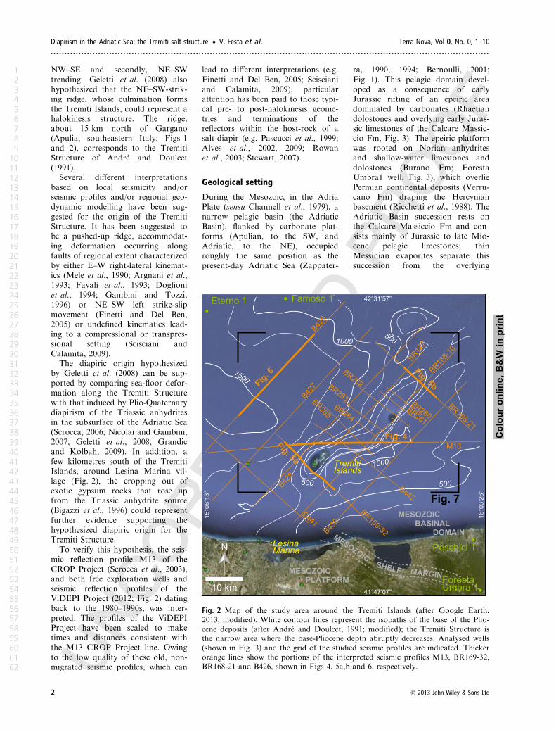
Fig. 2 Map of the study area around the Tremiti Islands (after Google Earth,
2013; modified). White contour lines represent the isobaths of the base of the Plio-
cene deposits (after Andr�e and Doulcet, 1991; modified); the Tremiti Structure is
the narrow area where the base-Pliocene depth abruptly decreases. Analysed wells
(shown in Fig. 3) and the grid of the studied seismic profiles are indicated. Thicker
orange lines show the portions of the interpreted seismic profiles M13, BR169-32,
BR168-21 and B426, shown in Figs 4, 5a,b and 6, respectively.
Colouronline,B&W
inprint
2 © 2013 John Wiley & Sons Ltd
Diapirism in the Adriatic Sea: the Tremiti salt structure • V. Festa et al. Terra Nova, Vol 0, No. 0, 1–10
.............................................................................................................................................................
1
2
3
4
5
6
7
8
9
10
11
12
13
14
15
16
17
18
19
20
21
22
23
24
25
26
27
28
29
30
31
32
33
34
35
36
37
38
39
40
41
42
43
44
45
46
47
48
49
50
51
52
53
54
55
56
57
58
59
60
61
62
Foresta Umbra 1
Marne a Fucoidi
Late Lias
Aquit.-Langh.
Eterno 1
Plio
-Qu
ate
rna
ry
Schlier
Scaglia Cinerea Bisciaro
Gessoso-
Scaglia Calcarea
Maiolica
Calcari ad Aptici
Rosso Ammonitico
Corniola
Calcare Massiccio Fm
2270 m
0 m(–160 m)
Peschici 1
Maiolica
Marne a Fucoidi
Calcari ad Aptici
0 m(55 m)
1275 m
Aptian-Albian
Late
Ju
rass
icM
idd
le
Jura
ssic
Ea
rly
Jura
ssic
Ea
rly
Cre
tace
ou
sMiddle Lias
Dogger - Malm
Early Lias
La
te C
reta
ceo
us-
Eo
cen
e
Oligoc.
Serrav.-Torton.
Messin.
Rh
ae
tia
nN
ori
an
Bu
ran
o F
m
Ea
rly
-Mid
dle
Ju
rass
ic
Pe
rsis
ten
t sh
all
ow
-wa
ter
con
dit
ion
s th
rou
gh
th
e E
arl
y-M
idd
le J
ura
ssic
Late
Ju
rass
ic
Rip
e R
oss
e F
m
Ca
lca
ri a
d A
pti
ci
eq
uiv
. in
slo
pe
fa
cie
s
0 m(809 m)
5912 m
Lithology
Marly limestones and marls
Limestones
Cherty limestones
Dolostones
Anhydrites
?
Seismostratigraphic units
Base of Pliocene
Top of
Calcare Massiccio Fm
Top of
Triassic anhydrites
A
B
C
D
Vp = 1800 m/s
Thickness: variable, up to 1400 m
Vp = 4100 m/s
Thickness: variable, up to 2600 m
Vp = 5900 m/s
Thickness: variable, up to 2500 m
Vp = 6400 m/s
0
300
600
900m
3290 m
Marne a Fucoidi
Famoso 1
Plio
-Qu
ate
rna
ry
Gessoso-
Schlier
Scaglia Cinerea
Scaglia Calcarea
Maiolica
Calcari ad Aptici
RossoAmmonitico
Corniola
Calcare Massiccio Fm
Messinian
Ea
rly
Lia
sciss
air T et
aL
Middle Lias
Late Lias
Dogger -
Malm
Thitonian-Barremian
Aptian-Albian
Cenomanian-middle Eocene
Late Eocene-middle Oligocene
Tortonian
0 m(–143 m)
4303 m
3126 m
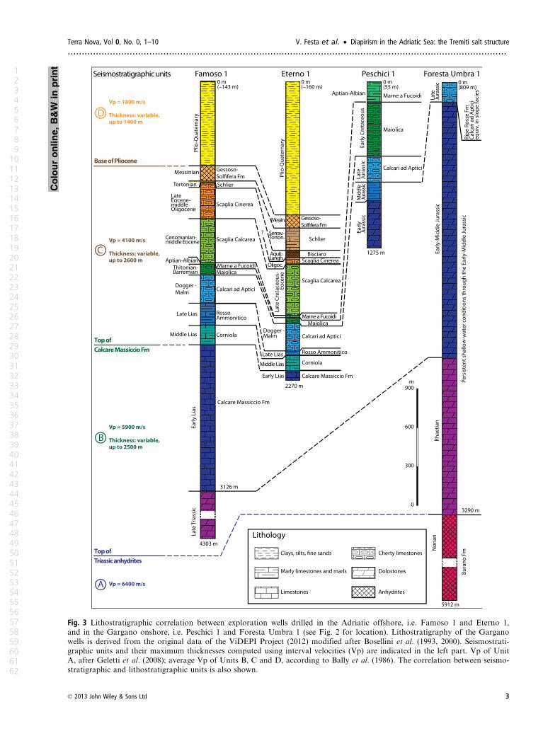
Fig. 3 Lithostratigraphic correlation between exploration wells drilled in the Adriatic offshore, i.e. Famoso 1 and Eterno 1,
and in the Gargano onshore, i.e. Peschici 1 and Foresta Umbra 1 (see Fig. 2 for location). Lithostratigraphy of the Gargano
wells is derived from the original data of the ViDEPI Project (2012) modified after Bosellini et al. (1993, 2000). Seismostrati-
graphic units and their maximum thicknesses computed using interval velocities (Vp) are indicated in the left part. Vp of Unit
A, after Geletti et al. (2008); average Vp of Units B, C and D, according to Bally et al. (1986). The correlation between seismo-
stratigraphic and lithostratigraphic units is also shown.
Colouronline,B&W
inprint
© 2013 John Wiley & Sons Ltd 3
Terra Nova, Vol 0, No. 0, 1–10 V. Festa et al. • Diapirism in the Adriatic Sea: the Tremiti salt structure
............................................................................................................................................................
1
2
3
4
5
6
7
8
9
10
11
12
13
14
15
16
17
18
19
20
21
22
23
24
25
26
27
28
29
30
31
32
33
34
35
36
37
38
39
40
41
42
43
44
45
46
47
48
49
50
51
52
53
54
55
56
57
58
59
60
61
62

Plio-Pleistocene foreland basin clays
(Santantonio et al., 2013; Famoso1
and Eterno1 wells, Fig. 3).
Seismic stratigraphy
Four main seismostratigraphic units
(A–D, from the bottom; Fig. 3) were
identified in the studied area by
reviewing seismic- and well-data in
accordance with the most recent liter-
ature (e.g. Santantonio et al., 2013).
Unit A, exhibiting a semi-transpar-
ent seismic facies topped by a high
amplitude reflector (e.g. Fig. 4), is
represented by the anhydritic portion
of the Burano Fm.
Unit B, topped by a strong reflec-
tor, exhibits discontinuous and
poorly defined reflectors (Figs 4, 5a,b
and 6), and consists of Burano Fm
limestones and dolostones, Rhaetian
dolostones and Calcare Massiccio
Fm limestones (Fig. 3).
Unit C groups middle Lias to
Messinian lithostratigraphic units
(Famoso 1 and Eterno 1 wells,
Fig. 3) corresponding to the Adriatic
Basin succession. It shows well-
defined, continuous, subparallel
reflectors and is topped by strong
reflectors of the Gessoso-Solfifera
Fm (Figs 4, 5a,b and 6). In the Tre-
miti Islands, the top of the unit crops
out, in the form of an angular
unconformity between tilted Palaeo-
cene, Eocene and Miocene (Langhian
to early Tortonian) rocks below and
thin Plio-Pleistocene deposits above
(Cremonini et al.,1971; Andriani
et al., 2005; Brozzetti et al., 2006;
Miccadei et al., 2011).
Finally, Unit D consists of Plio-
Quaternary emipelagites (Famoso 1,
Eterno 1 wells, Fig. 3), and is char-
acterized by some continuous reflec-
tors, and, locally, semi-transparent
seismic facies (Figs 4, 5a,b and 6).
Seismic interpretation of theTremiti Structure
The interpretation of seismic lines
along the Tremiti Structure required
first the identification of the top of
Unit A in poorly deformed areas. In
agreement with the literature (Finetti
and Del Ben, 2005; Geletti et al.,
2008; Scisciani and Calamita, 2009),
the top of Unit A around the Tremiti
Structure has been located at c. 3.5 s
in seismic profile M13 (Fig. 4). Con-
sidering the interval velocities (Vp) of
the overlying sedimentary rocks, a
depth of ca. 4500 m has been calcu-
lated for this high amplitude reflector.
Along the Tremiti Structure
(Figs 4 and 5a,b), seismic wave dif-
fractions, reflected refractions and
velocity distortion phenomena
strongly suggest halokinesis of the
Triassic anhydrites. In addition, and
as shown on seismic profile M13, the
same seismic record may result from
a fault located above the steeply
inclined eastern flank of a halokinesis
structure, i.e. the Tremiti diapir
(Fig. 4). A chaotic and poorly
defined seismic signal typically char-
acterizes the diapir, while the reflec-
tors of the wall-rock appear
generally continuous and better
developed. Often, the reflected refrac-
tions, in association with the steeply
inclined flanks of the diapir, can be
observed crosscutting the primary
reflections of the host Unit B and the
lowermost part of Unit C (Figs 4
and 5a,b). Due to the relatively high
Vp value of the anhydrites, the
reflections related to the interbedded
dolostones are affected by velocity
pull-up phenomena within the diapir.
The top of the diapir stands at c.
1.8 s in seismic profile M13 (Fig. 4),
and between c. 0.4 and 0.8 s in the
profiles BR168-21 and BR169-32
(Fig. 5a,b). Considering the Vp value
of the overlying sediments, the roof
is at a minimum depth of c. 750 m
from the sea bottom. Therefore, the
diapir has risen up to c. 3750 m from
the Triassic anhydrite source.
On the flanks of the diapir, reflec-
tors of Unit B, which has a nearly
constant thickness, and Unit A are
geometrically concordant. In con-
trast, the overlying units C and D
exhibit variable thickness. Unit C is
definitely thinner above the diapir,
while an abrupt increase in thickness
is observed laterally, especially on the
eastern and southeastern sides (Figs 4
and 5a,b). A local thickening of this
B428 B430
0
1
2
3
4
BR169-32
s
TWTW - E
Salt
diapir
Unit D
Unit B
Unit A - anhydrites
Unit C
0
1
2
3
4
5 km
Fig. 4 Uninterpreted (above) and interpreted (below) non-migrated and multi-chan-
nel stacked seismic profile M13 (see Fig. 2 for location).
Colouronline,B&W
inprint
4 © 2013 John Wiley & Sons Ltd
Diapirism in the Adriatic Sea: the Tremiti salt structure • V. Festa et al. Terra Nova, Vol 0, No. 0, 1–10
.............................................................................................................................................................
1
2
3
4
5
6
7
8
9
10
11
12
13
14
15
16
17
18
19
20
21
22
23
24
25
26
27
28
29
30
31
32
33
34
35
36
37
38
39
40
41
42
43
44
45
46
47
48
49
50
51
52
53
54
55
56
57
58
59
60
61
62

unit can be appreciated in the western
sector of seismic profile M13, i.e. on
the hangingwalls of synsedimentary
faults showing a dip-slip component
(Fig. 4). These faults belong to a sys-
tem of NE-dipping extensional faults
(Fig. 6), which determined thickness
variations in the lower part of Unit C
(Figs 4 and 6) and likely of Unit B
(Fig. 6) during the Mesozoic exten-
sional stage linked to the Jurassic rif-
ting. The abrupt increase in thickness
observed on the eastern side of the
Tremiti Structure along seismic pro-
file M13 (Fig. 4) is additional evi-
dence of extensional tectonics.
Furthermore, a low-amplitude ridge
structure, involving the NE-dipping
faults (Fig. 6), developed with a NW–
SE trend (Fig. 7).
On the flanks of the Tremiti Struc-
ture, reflectors show that gentle drag
folds involve both Unit B (Fig. 5a,b)
and the lower part of Unit C (Figs 4
and 5a,b), which were upturned by
rising anhydrite. From the sides to
the roof of the diapir, the geometries
of reflectors within the wall-rock are
compatible with an open, asymmet-
ric anticline affecting both Unit B
and Unit C (Figs 4 and 5a,b), which
is thinner in its uppermost portion
(e.g. Fig. 5a). As shown on seismic
profile M13 (Fig. 4), compressive
minor faults have been recognized in
the eastern side of the diapir. In
Unit D, internal unconformities, and
reflectors recording upturned strata,
are locally observed. Furthermore,
the unit exhibits a decrease in thick-
ness approaching the anticline,
whose crest is truncated by an
erosional surface (Figs 4 and 5a,b).
The latter corresponds to an
unconformity below the apparently
undisturbed Plio-Quaternary sedi-
ments.
According to well-known shape
classifications of salt structures (Jack-
son and Talbot, 1991; Stewart, 2007;
Guerra and Underhill, 2012), a salt-
anticline-type geometry may be
inferred from the seismic profiles of
the Tremiti diapir, which is c. 7–
8 km wide (Fig. 5a,b). In map view,
the salt-anticline is developed for c.
30 km and its axial-plane trace is
arched with a gentle concavity
towards the NW; northwards, it
strikes NNE–SSW, whereas south-
wards, it curves towards an ENE–
WSW trend (Fig. 7). A strong
asymmetry of this salt-anticline can
be appreciated in seismic profile M13
(Fig. 4), i.e. along the intermediate
part of the NE–SW-striking Tremiti
diapir (Fig. 7).
Discussion: age and mode ofhalokinesis
Two stages of halokinesis of the Tri-
assic anhydrites can be recognized in
the Tremiti Islands area.
0
1
2
BR127
NW - SE
Salt
diapir
s
TWT
5 km
0
1
2
NW - SE
BR168-10B428M13
s
TWT
Salt
diapir
0
1
2
5 km
BR168-10
Unit D
Unit B
Unit C
Unit D
Unit B
Unit C
(a)
(b)
Fig. 5 (a) Uninterpreted (above) and interpreted (below) non-migrated and multi-
channel stacked seismic profile BR169-32 (see Fig. 2 for location). (b) Uninter-
preted (left) and interpreted (right) non-migrated and multi-channel stacked seismic
profile BR168-21 (see Fig. 2 for location).
Colouronline,B&W
inprint
© 2013 John Wiley & Sons Ltd 5
Terra Nova, Vol 0, No. 0, 1–10 V. Festa et al. • Diapirism in the Adriatic Sea: the Tremiti salt structure
............................................................................................................................................................
1
2
3
4
5
6
7
8
9
10
11
12
13
14
15
16
17
18
19
20
21
22
23
24
25
26
27
28
29
30
31
32
33
34
35
36
37
38
39
40
41
42
43
44
45
46
47
48
49
50
51
52
53
54
55
56
57
58
59
60
61
62
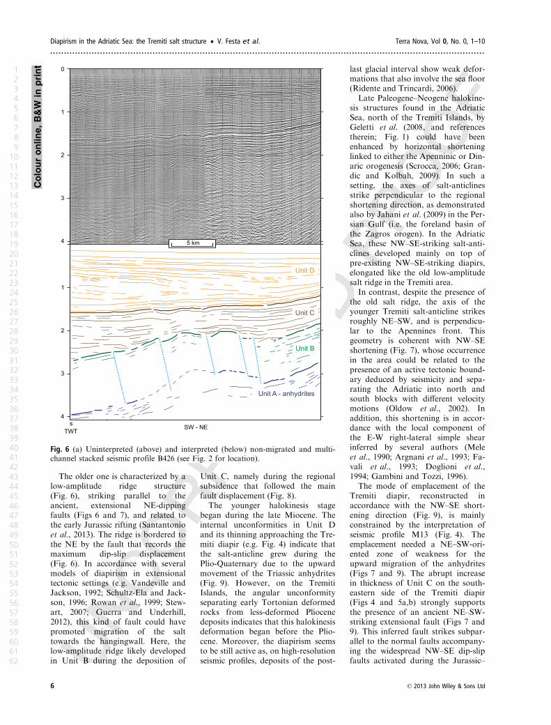
The older one is characterized by a
low-amplitude ridge structure
(Fig. 6), striking parallel to the
ancient, extensional NE-dipping
faults (Figs 6 and 7), and related to
the early Jurassic rifting (Santantonio
et al., 2013). The ridge is bordered to
the NE by the fault that records the
maximum dip-slip displacement
(Fig. 6). In accordance with several
models of diapirism in extensional
tectonic settings (e.g. Vandeville and
Jackson, 1992; Schultz-Ela and Jack-
son, 1996; Rowan et al., 1999; Stew-
art, 2007; Guerra and Underhill,
2012), this kind of fault could have
promoted migration of the salt
towards the hangingwall. Here, the
low-amplitude ridge likely developed
in Unit B during the deposition of
Unit C, namely during the regional
subsidence that followed the main
fault displacement (Fig. 8).
The younger halokinesis stage
began during the late Miocene. The
internal unconformities in Unit D
and its thinning approaching the Tre-
miti diapir (e.g. Fig. 4) indicate that
the salt-anticline grew during the
Plio-Quaternary due to the upward
movement of the Triassic anhydrites
(Fig. 9). However, on the Tremiti
Islands, the angular unconformity
separating early Tortonian deformed
rocks from less-deformed Pliocene
deposits indicates that this halokinesis
deformation began before the Plio-
cene. Moreover, the diapirism seems
to be still active as, on high-resolution
seismic profiles, deposits of the post-
last glacial interval show weak defor-
mations that also involve the sea floor
(Ridente and Trincardi, 2006).
Late Paleogene–Neogene halokine-
sis structures found in the Adriatic
Sea, north of the Tremiti Islands, by
Geletti et al. (2008, and references
therein; Fig. 1) could have been
enhanced by horizontal shortening
linked to either the Apenninic or Din-
aric orogenesis (Scrocca, 2006; Gran-
dic and Kolbah, 2009). In such a
setting, the axes of salt-anticlines
strike perpendicular to the regional
shortening direction, as demonstrated
also by Jahani et al. (2009) in the Per-
sian Gulf (i.e. the foreland basin of
the Zagros orogen). In the Adriatic
Sea, these NW–SE-striking salt-anti-
clines developed mainly on top of
pre-existing NW–SE-striking diapirs,
elongated like the old low-amplitude
salt ridge in the Tremiti area.
In contrast, despite the presence of
the old salt ridge, the axis of the
younger Tremiti salt-anticline strikes
roughly NE–SW, and is perpendicu-
lar to the Apennines front. This
geometry is coherent with NW–SE
shortening (Fig. 7), whose occurrence
in the area could be related to the
presence of an active tectonic bound-
ary deduced by seismicity and sepa-
rating the Adriatic into north and
south blocks with different velocity
motions (Oldow et al., 2002). In
addition, this shortening is in accor-
dance with the local component of
the E-W right-lateral simple shear
inferred by several authors (Mele
et al., 1990; Argnani et al., 1993; Fa-
vali et al., 1993; Doglioni et al.,
1994; Gambini and Tozzi, 1996).
The mode of emplacement of the
Tremiti diapir, reconstructed in
accordance with the NW–SE short-
ening direction (Fig. 9), is mainly
constrained by the interpretation of
seismic profile M13 (Fig. 4). The
emplacement needed a NE–SW-ori-
ented zone of weakness for the
upward migration of the anhydrites
(Figs 7 and 9). The abrupt increase
in thickness of Unit C on the south-
eastern side of the Tremiti diapir
(Figs 4 and 5a,b) strongly supports
the presence of an ancient NE–SW-
striking extensional fault (Figs 7 and
9). This inferred fault strikes subpar-
allel to the normal faults accompany-
ing the widespread NW–SE dip-slip
faults activated during the Jurassic–
0
1
2
3
4
1
2
3
4
5 km
s
TWTSW - NE
Unit D
Unit B
Unit A - anhydrites
Unit C
Fig. 6 (a) Uninterpreted (above) and interpreted (below) non-migrated and multi-
channel stacked seismic profile B426 (see Fig. 2 for location).
Colouronline,B&W
inprint
6 © 2013 John Wiley & Sons Ltd
Diapirism in the Adriatic Sea: the Tremiti salt structure • V. Festa et al. Terra Nova, Vol 0, No. 0, 1–10
.............................................................................................................................................................
1
2
3
4
5
6
7
8
9
10
11
12
13
14
15
16
17
18
19
20
21
22
23
24
25
26
27
28
29
30
31
32
33
34
35
36
37
38
39
40
41
42
43
44
45
46
47
48
49
50
51
52
53
54
55
56
57
58
59
60
61
62
Cretaceous (Festa, 2003; Santantonio
et al., 2013). Much later, during the
NW-SE shortening, the anhydrites
migrated in the footwall of the fault,
beneath Unit B (Fig. 9). Above the
southeastern flank of the diapir, the
growth of the anhydritic body deter-
mined an upward propagation, with
a dip-slip displacement, of the
ancient fault (Fig. 9). Drape upbend-
ing of Units B and C occurred, and
an asymmetric salt-anticline devel-
oped (Figs 4 and 9). In addition, the
NW–SE shortening may have led to
the arching of this fault, which has a
gentle concavity towards the NW
(Fig. 7).
Towards the north-east and south-
west terminations of the salt-anticline
(Fig. 7), the anhydrites simply used
the weakened zone of the ancient
fault as a preferential channel for
their upward migration through Unit
B (e.g. Fig. 10). Upward dragging of
Unit B, piercing of the lower part of
Unit C, and folding of the intermedi-
ate and upper parts of this unit also
occurred (Fig. 5a,b). In addition, in
the south-west termination of the
salt-anticline, an inversion of the
ancient dip-slip fault, which occurred
during piercing of the anhydrites,
would explain both the highest posi-
tion of Unit C, and the thinness of
Unit D in the hangingwall, compared
with the footwall (Fig. 10).
Concluding remarks
The occurrence of the Tremiti ridge
and its outstanding size are the
result of late Miocene to present-day
salt tectonics overprinting a Meso-
zoic low-amplitude salt ridge. A
halokinesis structure, the Tremiti
diapir, made up of Triassic anhy-
drites, is located beneath this ridge.
The Tremiti diapir forms an anti-
cline whose axis is approximately
perpendicular to both the elonga-
tions of most of the Neogene dia-
pirs, and the Apenninic and Dinaric
fronts, which strike NW–SE in the
sector of the Adriatic Sea north of
Gargano Promontory. The develop-
ment of this diapir required NW–SE
shortening, and occurred along a
pre-existing SE-dipping extensional
fault, whose origin dates back to the
Jurassic–Cretaceous. In its central
part, the diapir was emplaced in the
footwall of this fault. Both shorten-
Shortening
BR169-32
BR168-21
M13
Fig. 4
Fig. 5b
B42
6
Fig. 6
10 km
N
dip-slip faultsMesozoic
15°1
3’2
4”
42°02’38”
15°5
8’4
9”
42°26’09”
AnticlineaxisM
esozoic low-am
plitude ascent of the
Fault
Tremiti diapir
Fig. 9
Fig. 9
anhydritic ridge
Fig.
8
favouring the
Saltanticline,i.e. Tremitidiapir
Fig. 10Tremitidiapir
Tremitiridge
Fig. 5a
TremitiIslands
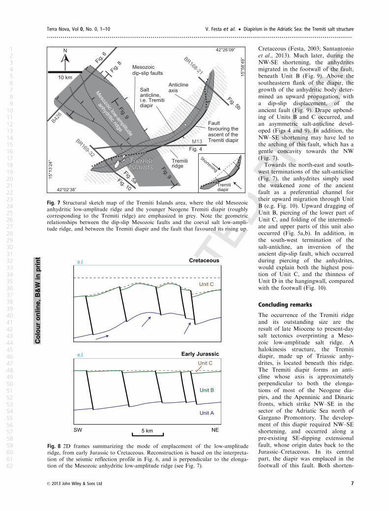
Fig. 7 Structural sketch map of the Tremiti Islands area, where the old Mesozoic
anhydritic low-amplitude ridge and the younger Neogene Tremiti diapir (roughly
corresponding to the Tremiti ridge) are emphasized in grey. Note the geometric
relationships between the dip-slip Mesozoic faults and the coeval salt low-ampli-
tude ridge, and between the Tremiti diapir and the fault that favoured its rising up.
Unit B
Unit C
Early Jurassic
Unit C
Cretaceous
Unit A
5 km NESW
s.l.
s.l.
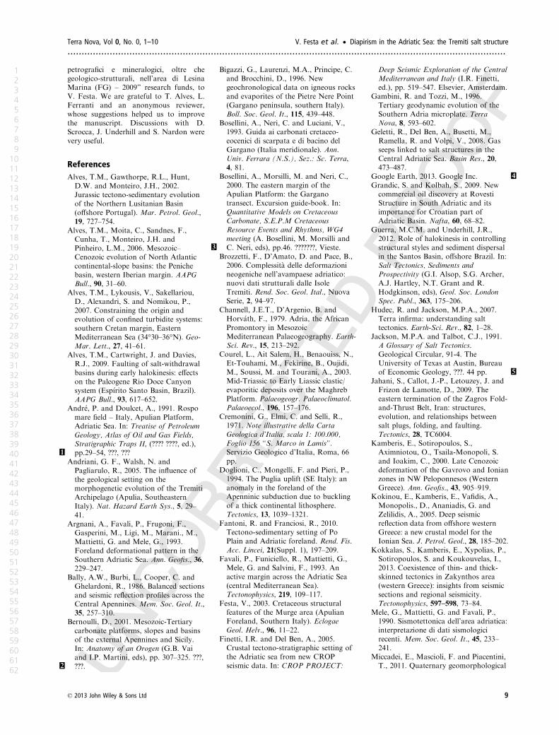
Fig. 8 2D frames summarizing the mode of emplacement of the low-amplitude
ridge, from early Jurassic to Cretaceous. Reconstruction is based on the interpreta-
tion of the seismic reflection profile in Fig. 6, and is perpendicular to the elonga-
tion of the Mesozoic anhydritic low-amplitude ridge (see Fig. 7).
Colouronline,B&W
inprint
© 2013 John Wiley & Sons Ltd 7
Terra Nova, Vol 0, No. 0, 1–10 V. Festa et al. • Diapirism in the Adriatic Sea: the Tremiti salt structure
............................................................................................................................................................
1
2
3
4
5
6
7
8
9
10
11
12
13
14
15
16
17
18
19
20
21
22
23
24
25
26
27
28
29
30
31
32
33
34
35
36
37
38
39
40
41
42
43
44
45
46
47
48
49
50
51
52
53
54
55
56
57
58
59
60
61
62

ing and upward growth of the diapir
were able to uplift the entire foot-
wall. As a consequence, upward
propagation of the fault with dip-
slip kinematics occurred. Towards
the terminations of the diapir, the
fault, which was locally reactivated
with reverse kinematics, represented
a path for the upward migration
and squeezing of the anhydrites,
which pierced and folded the above
wall-rock.
These results could represent an
interpretive key for the scattered
halokinetic structures occurring in
the Adriatic Basin, north of the
Tremiti Islands. NW-SE-elongated
diapirs originally developed during
the Mesozoic in the form of low-
amplitude ridges, whose geometric
features were driven by the activity
of extensional faults. During the
Neogene, two sets of diapirs with
opposite elongations developed. The
most representative set consists of
halokinesis structures that grew on
top of, and parallel to, the pre-exist-
ing low-amplitude diapirs. Their fold
axes strike NW–SE, i.e. perpendicu-
lar to the shortening direction due to
the opposite propagation of the
Apenninic and Dinaric fronts. In
contrast, NW–SE shortening could
have locally promoted both salt
mobilization and NE–SW-elongated
salt-anticlines representing the other
set. These halokinesis structures
developed parallel to the Tremiti dia-
pir, likely along Jurassic–Cretaceous
faults.
Acknowledegments
This study was supported by “Convenzi-
one tra Autorit�a di Bacino della Puglia e
Dipartimento Geomineralogico dell’Uni-
versit�a degli Studi di Bari per studi
Pleistocene
Present-days.l.
s.l.
Unit D
Late Miocene
Pliocene
Unit C
Unit B
Unit A
10 km SENW
s.l.
s.l.
Fig. 9 2D frames summarizing the mode of emplacement of the Tremiti diapir, from late Miocene to present-day. Reconstruc-
tion is based on the interpretation of the seismic profile M13 (Fig. 4), and is subparallel to the elongation of the old Mesozoic
anhydritic low-amplitude ridge (see Fig. 7).
5 km SENW
s.l.
Unit C
Unit B
Unit A
Unit D
Fig. 10 2D schematic interpretation of the seismic profile BR169-32 (Fig. 5a),
crossing the southwestern termination of the Tremiti diapir (see Fig. 7 for loca-
tion). The path taken during upward migration and squeezing of the anhydrites is
indicated by the blue arrows, near the fault plane. Note in Unit C, piercing and
folding due to the Tremiti diapir. The inversion of the originally dip-slip fault is
indicated by the red arrow. The highest position of Unit C, and the thinness of
Unit D in the hangingwall, compared with the footwall, can be appreciated.
Colouronline,B&W
inprint
8 © 2013 John Wiley & Sons Ltd
Diapirism in the Adriatic Sea: the Tremiti salt structure • V. Festa et al. Terra Nova, Vol 0, No. 0, 1–10
.............................................................................................................................................................
1
2
3
4
5
6
7
8
9
10
11
12
13
14
15
16
17
18
19
20
21
22
23
24
25
26
27
28
29
30
31
32
33
34
35
36
37
38
39
40
41
42
43
44
45
46
47
48
49
50
51
52
53
54
55
56
57
58
59
60
61
62
petrografici e mineralogici, oltre che
geologico-strutturali, nell’area di Lesina
Marina (FG) – 2009” research funds, to
V. Festa. We are grateful to T. Alves, L.
Ferranti and an anonymous reviewer,
whose suggestions helped us to improve
the manuscript. Discussions with D.
Scrocca, J. Underhill and S. Nardon were
very useful.
References
Alves, T.M., Gawthorpe, R.L., Hunt,
D.W. and Monteiro, J.H., 2002.
Jurassic tectono-sedimentary evolution
of the Northern Lusitanian Basin
(offshore Portugal). Mar. Petrol. Geol.,
19, 727–754.
Alves, T.M., Moita, C., Sandnes, F.,
Cunha, T., Monteiro, J.H. and
Pinheiro, L.M., 2006. Mesozoic–
Cenozoic evolution of North Atlantic
continental-slope basins: the Peniche
basin, western Iberian margin. AAPG
Bull., 90, 31–60.
Alves, T.M., Lykousis, V., Sakellariou,
D., Alexandri, S. and Nomikou, P.,
2007. Constraining the origin and
evolution of confined turbidite systems:
southern Cretan margin, Eastern
Mediterranean Sea (34°30–36°N). Geo-
Mar. Lett., 27, 41–61.
Alves, T.M., Cartwright, J. and Davies,
R.J., 2009. Faulting of salt-withdrawal
basins during early halokinesis: effects
on the Paleogene Rio Doce Canyon
system (Esp�ırito Santo Basin, Brazil).
AAPG Bull., 93, 617–652.
Andr�e, P. and Doulcet, A., 1991. Rospo
mare field – Italy, Apulian Platform,
Adriatic Sea. In: Treatise of Petroleum
Geology, Atlas of Oil and Gas Fields,
Stratigraphic Traps II, (???? ????, ed.),
pp.29–54, ???, ???1
Andriani, G. F., Walsh, N. and
Pagliarulo, R., 2005. The influence of
the geological setting on the
morphogenetic evolution of the Tremiti
Archipelago (Apulia, Southeastern
Italy). Nat. Hazard Earth Sys., 5, 29–
41.
Argnani, A., Favali, P., Frugoni, F.,
Gasperini, M., Ligi, M., Marani., M.,
Mattietti, G. and Mele, G., 1993.
Foreland deformational pattern in the
Southern Adriatic Sea. Ann. Geofis., 36,
229–247.
Bally, A.W., Burbi, L., Cooper, C. and
Ghelardoni, R., 1986. Balanced sections
and seismic reflection profiles across the
Central Apennines. Mem. Soc. Geol. It.,
35, 257–310.
Bernoulli, D., 2001. Mesozoic-Tertiary
carbonate platforms, slopes and basins
of the external Apennines and Sicily.
In: Anatomy of an Orogen (G.B. Vai
and I.P. Martini, eds), pp. 307–325. ???,
???.2
Bigazzi, G., Laurenzi, M.A., Principe, C.
and Brocchini, D., 1996. New
geochronological data on igneous rocks
and evaporites of the Pietre Nere Point
(Gargano peninsula, southern Italy).
Boll. Soc. Geol. It., 115, 439–448.
Bosellini, A., Neri, C. and Luciani, V.,
1993. Guida ai carbonati cretaceo-
eocenici di scarpata e di bacino del
Gargano (Italia meridionale). Ann.
Univ. Ferrara (N.S.), Sez.: Sc. Terra,
4, 81.
Bosellini, A., Morsilli, M. and Neri, C.,
2000. The eastern margin of the
Apulian Platform: the Gargano
transect. Excursion guide-book. In:
Quantitative Models on Cretaceous
Carbonate, S.E.P.M Cretaceous
Resource Events and Rhythms, WG4
meeting (A. Bosellini, M. Morsilli and
C. Neri, eds), pp.46. ???????, Vieste.3
Brozzetti, F., D’Amato, D. and Pace, B.,
2006. Complessit�a delle deformazioni
neogeniche nell’avampaese adriatico:
nuovi dati strutturali dalle Isole
Tremiti. Rend. Soc. Geol. Ital., Nuova
Serie, 2, 94–97.
Channell, J.E.T., D’Argenio, B. and
Horv�ath, F., 1979. Adria, the African
Promontory in Mesozoic
Mediterranean Palaeogeography. Earth-
Sci. Rev., 15, 213–292.
Courel, L., Ait Salem, H., Benaouiss, N.,
Et-Touhami, M., Fekirine, B., Oujidi,
M., Soussi, M. and Tourani, A., 2003.
Mid-Triassic to Early Liassic clastic/
evaporitic deposits over the Maghreb
Platform. Palaeogeogr. Palaeoclimatol.
Palaeoecol., 196, 157–176.
Cremonini, G., Elmi, C. and Selli, R.,
1971. Note illustrative della Carta
Geologica d’Italia, scala 1: 100.000,
Foglio 156 “S. Marco in Lamis”.
Servizio Geologico d’Italia, Roma, 66
pp.
Doglioni, C., Mongelli, F. and Pieri, P.,
1994. The Puglia uplift (SE Italy): an
anomaly in the foreland of the
Apenninic subduction due to buckling
of a thick continental lithosphere.
Tectonics, 13, 1039–1321.
Fantoni, R. and Franciosi, R., 2010.
Tectono-sedimentary setting of Po
Plain and Adriatic foreland. Rend. Fis.
Acc. Lincei, 21(Suppl. 1), 197–209.
Favali, P., Funiciello, R., Mattietti, G.,
Mele, G. and Salvini, F., 1993. An
active margin across the Adriatic Sea
(central Mediterranean Sea).
Tectonophysics, 219, 109–117.
Festa, V., 2003. Cretaceous structural
features of the Murge area (Apulian
Foreland, Southern Italy). Eclogae
Geol. Helv., 96, 11–22.
Finetti, I.R. and Del Ben, A., 2005.
Crustal tectono-stratigraphic setting of
the Adriatic sea from new CROP
seismic data. In: CROP PROJECT:
Deep Seismic Exploration of the Central
Mediterranean and Italy (I.R. Finetti,
ed.), pp. 519–547. Elsevier, Amsterdam.
Gambini, R. and Tozzi, M., 1996.
Tertiary geodynamic evolution of the
Southern Adria microplate. Terra
Nova, 8, 593–602.
Geletti, R., Del Ben, A., Busetti, M.,
Ramella, R. and Volpi, V., 2008. Gas
seeps linked to salt structures in the
Central Adriatic Sea. Basin Res., 20,
473–487.
Google Earth, 2013. Google Inc. 4
Grandic, S. and Kolbah, S., 2009. New
commercial oil discovery at Rovesti
Structure in South Adriatic and its
importance for Croatian part of
Adriatic Basin. Nafta, 60, 68–82.
Guerra, M.C.M. and Underhill, J.R.,
2012. Role of halokinesis in controlling
structural styles and sediment dispersal
in the Santos Basin, offshore Brazil. In:
Salt Tectonics, Sediments and
Prospectivity (G.I. Alsop, S.G. Archer,
A.J. Hartley, N.T. Grant and R.
Hodgkinson, eds), Geol. Soc. London
Spec. Publ., 363, 175–206.
Hudec, R. and Jackson, M.P.A., 2007.
Terra infirma: understanding salt
tectonics. Earth-Sci. Rev., 82, 1–28.
Jackson, M.P.A. and Talbot, C.J., 1991.
A Glossary of Salt Tectonics.
Geological Circular, 91-4. The
University of Texas at Austin, Bureau
of Economic Geology, ???. 44 pp. 5
Jahani, S., Callot, J.-P., Letouzey, J. and
Frizon de Lamotte, D., 2009. The
eastern termination of the Zagros Fold-
and-Thrust Belt, Iran: structures,
evolution, and relationships between
salt plugs, folding, and faulting.
Tectonics, 28, TC6004.
Kamberis, E., Sotiropoulos, S.,
Aximniotou, O., Tsaila-Monopoli, S.
and Ioakim, C., 2000. Late Cenozoic
deformation of the Gavrovo and Ionian
zones in NW Peloponnesos (Western
Greece). Ann. Geofis., 43, 905–919.
Kokinou, E., Kamberis, E., Vafidis, A.,
Monopolis., D., Ananiadis, G. and
Zelilidis, A., 2005. Deep seismic
reflection data from offshore western
Greece: a new crustal model for the
Ionian Sea. J. Petrol. Geol., 28, 185–202.
Kokkalas, S., Kamberis, E., Xypolias, P.,
Sotiropoulos, S. and Koukouvelas, I.,
2013. Coexistence of thin- and thick-
skinned tectonics in Zakynthos area
(western Greece): insights from seismic
sections and regional seismicity.
Tectonophysics, 597–598, 73–84.
Mele, G., Mattietti, G. and Favali, P.,
1990. Sismotettonica dell’area adriatica:
interpretazione di dati sismologici
recenti. Mem. Soc. Geol. It., 45, 233–
241.
Miccadei, E., Mascioli, F. and Piacentini,
T., 2011. Quaternary geomorphological
© 2013 John Wiley & Sons Ltd 9
Terra Nova, Vol 0, No. 0, 1–10 V. Festa et al. • Diapirism in the Adriatic Sea: the Tremiti salt structure
............................................................................................................................................................
1
2
3
4
5
6
7
8
9
10
11
12
13
14
15
16
17
18
19
20
21
22
23
24
25
26
27
28
29
30
31
32
33
34
35
36
37
38
39
40
41
42
43
44
45
46
47
48
49
50
51
52
53
54
55
56
57
58
59
60
61
62

evolution of the Tremiti Islands
(Puglia, Italy). Quatern. Int., 233, 3–15.
Nicolai, C. and Gambini, R., 2007.
Structural architecture of the Adria
platform-and-basin system. Boll. Soc.
Geol. Ital., (Suppl. 7, 21–37.
Oldow, J.S., Ferranti, L., Lewis, D.S.,
Campbell, J.K., D’Argenio, B.,
Catalano, R., Pappone, G.,
Carmignani, L., Conti, P. and Aiken,
C.L.V, 2002. Active fragmentation of
Adria, the north African promontory,
central Mediterranean orogen. Geology,
30, 779–782.
Pascucci, V., Gibling, M.R. and
Williamson, M.A., 1999. Seismic
stratigraphic analysis of Carboniferous
strata on the Burin Platform, offshore
Eastern Canada. Bull. Can. Petrol.
Geol., 47, 298–316.
Ricchetti, G., Ciaranfi, N., Luperto Sinni,
E., Mongelli, F. and Pieri, P., 1988.
Geodinamica ed evoluzione sedimentaria
e tettonica dell’Avampaese Apulo. Mem.
Soc. Geol. It., 41, 57–82.
Ridente, D. and Trincardi, F., 2006.
Active foreland deformation evidenced
by shallow folds and faults affecting
late Quaternary shelf-slope deposits
(Adriatic Sea, Italy). Basin Res., 18,
171–188.
Rowan, M.G., Jackson, M.P.A. and
Trudgill, B.D., 1999. Salt-Related Fault
Families and Fault Welds in the
Northern Gulf of Mexico. AAPG Bull.,
83, 1454–1484.
Rowan, M.G., Lawton, T.F., Giles, K.A.
and Ratliff, R.A., 2003. Near-salt
deformation in La Popa basin, Mexico,
and the northern Gulf of Mexico: a
general model for passive diapirism.
AAPG Bull., 87, 733–756.
Santantonio, M., Scrocca, D. and
Lipparini, L., 2013. The Ombrina-
Rospo Plateau (Apulian Platform):
evolution of a Carbonate Platform and
its Margins during the Jurassic and
Cretaceous. Mar. Petrol. Geol., 42, 4–
29.
Schultz-Ela, D.D. and Jackson, M.P.A.,
1996. Relation of Subsalt Structures to
Suprasalt Structures During Extension.
AAPG Bull., 80, 1896–1924.
Scisciani, V. and Calamita, F., 2009.
Active intraplate deformation within
Adria: examples from the Adriatic
region. Tectonophysics, 476, 57–72.
Scrocca, D., 2006. Thrust front
segmentation induced by differential
slab retreat in the Apennines (Italy).
Terra Nova, 18, 154–161.
Scrocca, D., Doglioni, C., Innocenti, F.,
Manetti, P., Mazzotti, A., Bertelli, L.,
Burbi, L. and D’Offizi, S. (eds.), 2003.
CROP Atlas: seismic reflection profiles
of the Italian crust. Memorie Descrittive
della Carta Geologica d’Italia, 62, 193,
71 plates.
Stewart, S.A., 2007. Salt tectonics in the
North Sea Basin: a structural style
template for seismic interpreters. In:
Deformation of the Continental Crust:
The Legacy of Mike Coward (A.C.
Ries, R.W.H. Butler and R.H.
Graham, eds), Geol. Soc. London Spec.
Publ., 272, 361–396.
Underhill, J.R., 1988. Triassic evaporites
and Plio-Quaternary diapirism in
western Greece. J. Geol. Soc. London,
145, 269–282.
Vandeville, B.C. and Jackson, M.P.A.,
1992. The fall of diapirs during thin-
skinned extension. Mar. Petrol. Geol.,
9, 354–371.
ViDEPI Project, 2012 (last upgrade).
Progetto ViDEPI - Visibilit�a Dati
Esplorazione Petrolifera in Italia.
http://unmig.sviluppoeconomico.gov.it/
videpi/
Zappaterra, E., 1990. Carbonate
paleogeographic sequences of the
periadriatic region. Boll. Soc. Geol. It.,
109, 5–20.
Zappaterra, E., 1994. Source-rock
distribution model of the Periadriatic
region. AAPG Bull., 78, 333–354.
Zelilidis, A., Kontopoulos, N., Avramidis,
P. and Piper, D.J.W., 1998. Tectonic
and sedimentological evolution of the
Pliocene-Quaternary basins of
Zakynthos island, Greece: case study of
the transition from compressional to
extensional tectonics. Basin Res., 10,
393–408.
Received 4 June 2013; revised version
accepted 21 October 2013
10 © 2013 John Wiley & Sons Ltd
Diapirism in the Adriatic Sea: the Tremiti salt structure • V. Festa et al. Terra Nova, Vol 0, No. 0, 1–10
.............................................................................................................................................................
1
2
3
4
5
6
7
8
9
10
11
12
13
14
15
16
17
18
19
20
21
22
23
24
25
26
27
28
29
30
31
32
33
34
35
36
37
38
39
40
41
42
43
44
45
46
47
48
49
50
51
52
53
54
55
56
57
58
59
60
61
62
Author Query Form
Journal: TERArticle: 12082
Dear Author,
During the copy-editing of your paper, the following queries arose. Please respond to these by marking up
your proofs with the necessary changes/additions. Please write your answers on the query sheet if there is
insufficient space on the page proofs. Please write clearly and follow the conventions shown on the
attached corrections sheet. If returning the proof by fax do not write too close to the paper’s edge. Please
remember that illegible mark-ups may delay publication.
Many thanks for your assistance.
Query reference Query Remarks
1 AUTHOR: Please provide the publisher name, publisher location for reference
Andr�e and Doulcet (1991).
2 AUTHOR: Please provide the publisher name, publisher location for reference Ber-
noulli (2001).
3 AUTHOR: Please provide the publisher name for reference Bosellini et al. (2000).
4 AUTHOR: Please provide more details (if applicable) for reference Google Earth
(2013).
5 AUTHOR: Please provide the publisher location for reference Jackson and Talbot
(1991).
USING e-ANNOTATION TOOLS FOR ELECTRONIC PROOF CORRECTION
Required software to e-Annotate PDFs: Adobe Acrobat Professional or Adobe Reader (version 8.0 or
above). (Note that this document uses screenshots from Adobe Reader X)
The latest version of Acrobat Reader can be downloaded for free at: http://get.adobe.com/reader/
Once you have Acrobat Reader open on your computer, click on the Comment tab at the right of the toolbar:
1. Replace (Ins) Tool Î for replacing text.
Strikes a line through text and opens up a text
box where replacement text can be entered.
How to use it
‚ Highlight a word or sentence.
‚ Click on the Replace (Ins) icon in the Annotations
section.
‚ Type the replacement text into the blue box that
appears.
This will open up a panel down the right side of the document. The majority of
tools you will use for annotating your proof will be in the Annotations section,
rkevwtgf"qrrqukvg0"YgÓxg"rkemgf"qwv"uqog"qh"vjgug"vqqnu"dgnqy<
2. Strikethrough (Del) Tool Î for deleting text.
Strikes a red line through text that is to be
deleted.
How to use it
‚ Highlight a word or sentence.
‚ Click on the Strikethrough (Del) icon in the
Annotations section.
3. Add note to text Tool Î for highlighting a section
to be changed to bold or italic.
Highlights text in yellow and opens up a text
box where comments can be entered.
How to use it
‚ Highlight the relevant section of text.
‚ Click on the Add note to text icon in the
Annotations section.
‚ Type instruction on what should be changed
regarding the text into the yellow box that
appears.
4. Add sticky note Tool Î for making notes at
specific points in the text.
Marks a point in the proof where a comment
needs to be highlighted.
How to use it
‚ Click on the Add sticky note icon in the
Annotations section.
‚ Click at the point in the proof where the comment
should be inserted.
‚ Type the comment into the yellow box that
appears.

USING e-ANNOTATION TOOLS FOR ELECTRONIC PROOF CORRECTION
For further information on how to annotate proofs, click on the Help menu to reveal a list of further options:
5. Attach File Tool Î for inserting large amounts of
text or replacement figures.
Inserts an icon linking to the attached file in the
appropriate pace in the text.
How to use it
‚ Click on the Attach File icon in the Annotations
section.
‚ Enkem"qp"vjg"rtqqh"vq"yjgtg"{qwÓf"nkmg"vjg"cvvcejgf"file to be linked.
‚ Select the file to be attached from your computer
or network.
‚ Select the colour and type of icon that will appear
in the proof. Click OK.
6. Add stamp Tool Î for approving a proof if no
corrections are required.
Inserts a selected stamp onto an appropriate
place in the proof.
How to use it
‚ Click on the Add stamp icon in the Annotations
section.
‚ Select the stamp you want to use. (The Approved
stamp is usually available directly in the menu that
appears).
‚ Enkem"qp"vjg"rtqqh"yjgtg"{qwÓf"nkmg"vjg"uvcor"vq"appear. (Where a proof is to be approved as it is,
this would normally be on the first page).
7. Drawing Markups Tools Î for drawing shapes, lines and freeform
annotations on proofs and commenting on these marks.
Allows shapes, lines and freeform annotations to be drawn on proofs and for
comment to be made on these marks..
How to use it
‚ Click on one of the shapes in the Drawing
Markups section.
‚ Click on the proof at the relevant point and
draw the selected shape with the cursor.
‚ To add a comment to the drawn shape,
move the cursor over the shape until an
arrowhead appears.
‚ Double click on the shape and type any
text in the red box that appears.