Embed Size (px)
Citation preview
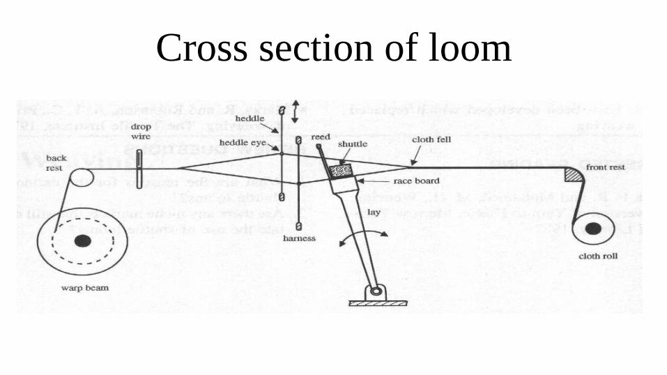
Cross section of loom
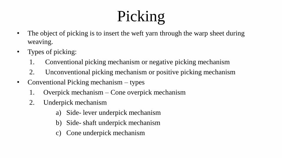
Picking• The object of picking is to insert the weft yarn through the warp sheet during
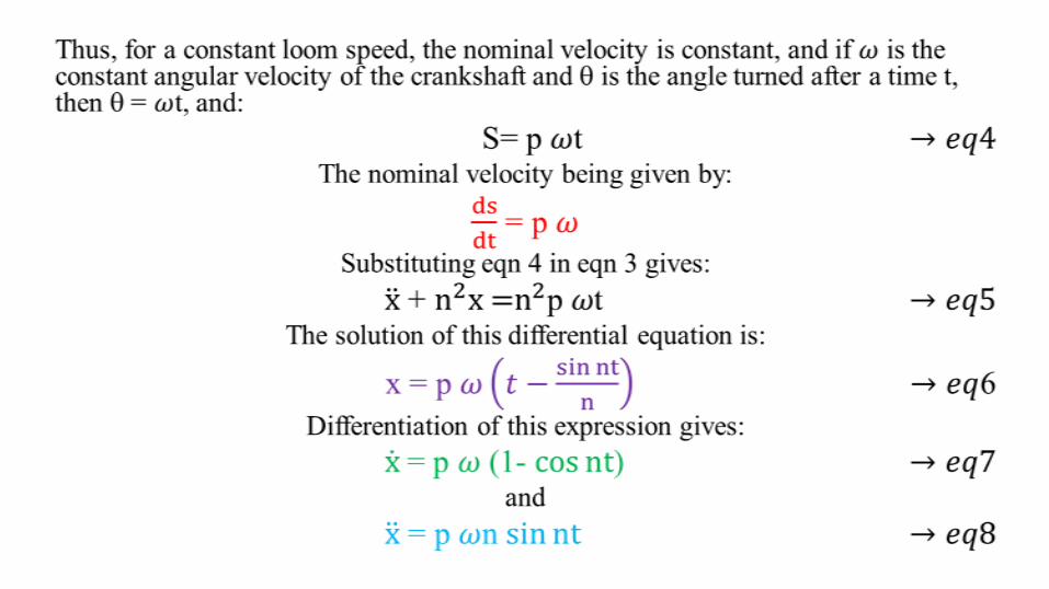
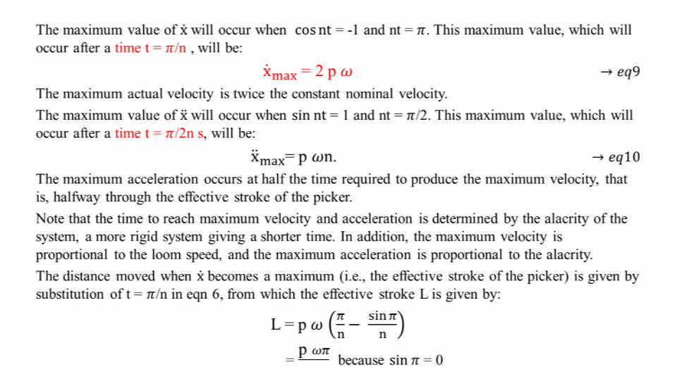
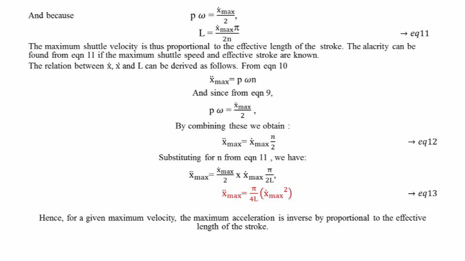
weaving.
• Types of picking:
1. Conventional picking mechanism or negative picking mechanism
2. Unconventional picking mechanism or positive picking mechanism
• Conventional Picking mechanism – types
1. Overpick mechanism – Cone overpick mechanism
2. Underpick mechanism
a) Side- lever underpick mechanism
b) Side- shaft underpick mechanism
c) Cone underpick mechanism
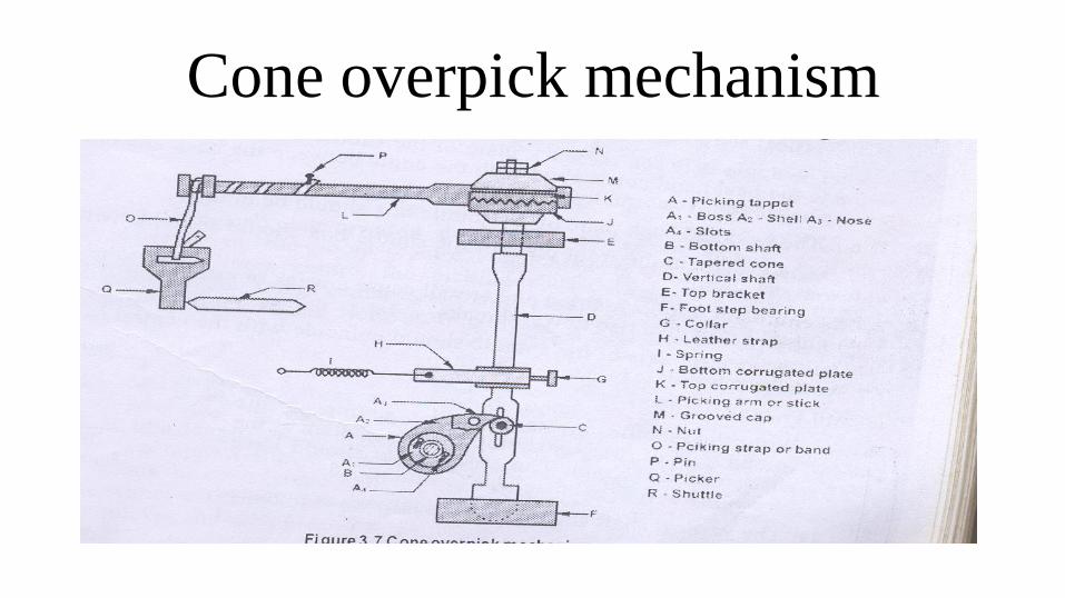
Cone overpick mechanism
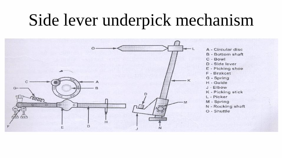
Side lever underpick mechanism
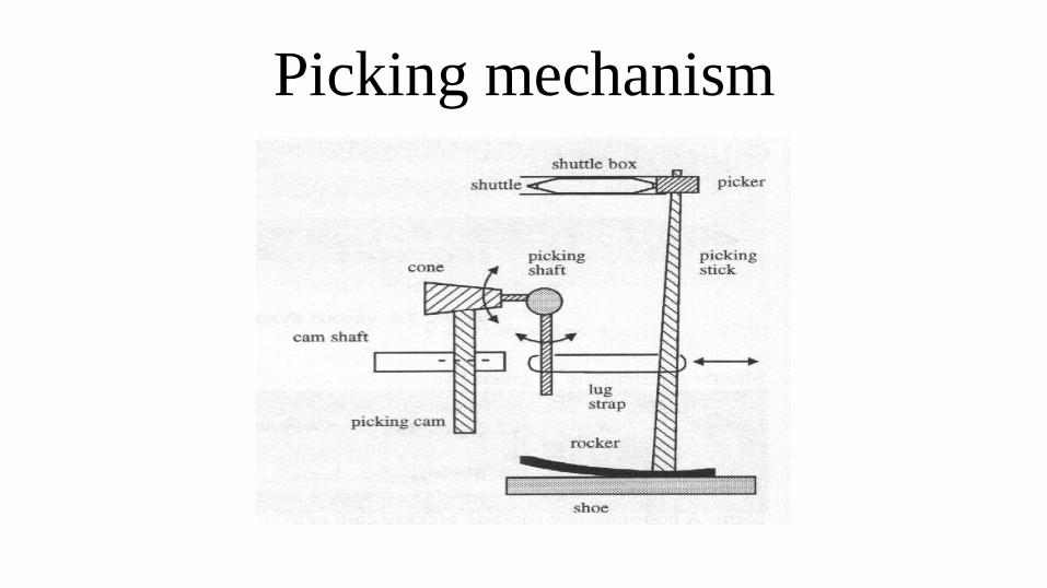
Picking mechanism
Picking mechanism• In shuttle weaving, the filling is inserted by a shuttle that traverses forth and
back across the loom width.
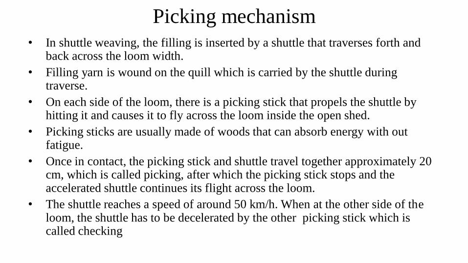
• Filling yarn is wound on the quill which is carried by the shuttle during traverse.
• On each side of the loom, there is a picking stick that propels the shuttle by hitting it and causes it to fly across the loom inside the open shed.
• Picking sticks are usually made of woods that can absorb energy with out fatigue.
• Once in contact, the picking stick and shuttle travel together approximately 20 cm, which is called picking, after which the picking stick stops and the accelerated shuttle continues its flight across the loom.
• The shuttle reaches a speed of around 50 km/h. When at the other side of the loom, the shuttle has to be decelerated by the other picking stick which is called checking
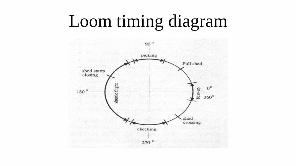
Loom Timing diagram
• All events on the loom are to be properly synchronised which can be demonstrated
on a loom timing diagram.
• However, all the basic motions of a loom have to be completed in 360°
• The shuttle starts moving at around 80° following the beatup.
• The contact between the shuttle and the picker lasts around 30° which corresponds
to approximately 20 cm.
• At this position, the shuttle reaches a speed of around 15 m/sec, the picker stops
pushing the shuttle and the shuttle flies across the loom by itself.
• Once at the other side of the loom, the shuttle is brought to a stop by the checking
mechanism which is similar to picking.
• Insertion with shuttle is an inefficient process in the sense, that the shuttle weighs
0.5 kg while the weight of the inserted weft is less than 1/1000 of the shuttle weight
Loom timing diagram
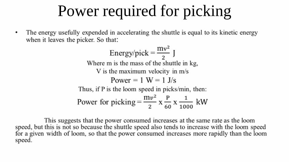
Power required for picking
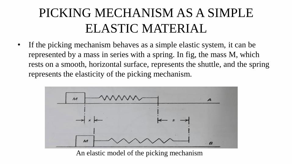
• If the picking mechanism behaves as a simple elastic system, it can be
represented by a mass in series with a spring. In fig, the mass M, which
rests on a smooth, horizontal surface, represents the shuttle, and the spring
represents the elasticity of the picking mechanism.
PICKING MECHANISM AS A SIMPLE
ELASTIC MATERIAL
An elastic model of the picking mechanism

Beat – up mechanism
Beat-up
• The object of the beatup mechanism is to push the last laid weft thread into
the fell of the cloth by means of a reed.
• Types of beat-up mechanism
1. Crank and connecting arm beat-up mechanism
2. Cam beat-up mechanism
• Reed:
A reed is a comb fixed in the sley by means of a cap at the top. It is
secured at the bottom in between the reed case and race board. The comb has
flat strips or wires spaced uniformly. The open space between two adjacent
wires is known as “dent”. The warp yarns are passed through the dents.
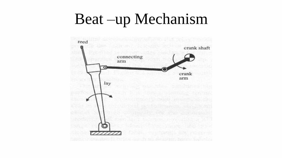
Beat –up Mechanism
Beat-up Mechanism
• After picking, the shuttle travels on the race board, the lower portion of the
warp yarns being in between the shuttle and the race board.
• The race board supports the shuttle while the reed helps guide the shuttle.
• The reed and the race board are assembled together which is called lay or
sley.
• The lay oscillates back and forth by two levers that are called lay swords.
• Lay swords pivot about rocking shafts which are driven by a crank and
connecting rod.
• The lay operates once every weaving cycle to beat-up the filling yarn and
performs a continuous harmonic motion.
Beating mechanism
•
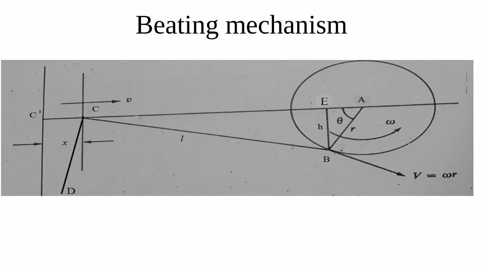
Beating mechanism• The beating mechanism is shown in fig. It will be seen that the mechanism
is in reality a four bar chain in which the loom frame forms the link AD.
• The link AB is the crank, the link BC is the connecting rod and the link CD
too will oscillate as required.
• It is highly desirable that the sley should stay in the back position as long as
possible so as to give the shuttle more time to pass.
• This requires that the sley should move in a fairly complex harmonic
motion.
• To simplify the motion, it is possible to assume that the point C along a
straight line rather than along an arc.
• For the purposes of explanation, let it be further assumed that the line of
action of C passes through A and that the loom speed remains constant.
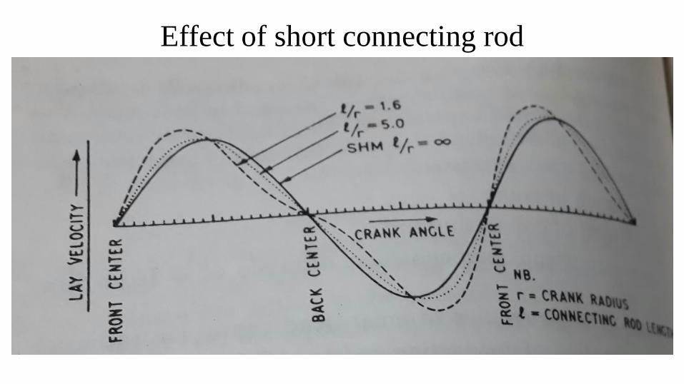
Effect of short connecting rod
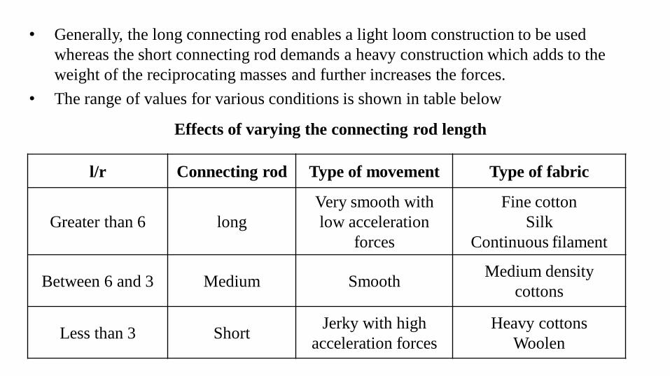
• Generally, the long connecting rod enables a light loom construction to be used
whereas the short connecting rod demands a heavy construction which adds to the
weight of the reciprocating masses and further increases the forces.
• The range of values for various conditions is shown in table below
l/r Connecting rod Type of movement Type of fabric
Greater than 6 long
Very smooth with
low acceleration
forces
Fine cotton
Silk
Continuous filament
Between 6 and 3 Medium SmoothMedium density
cottons
Less than 3 ShortJerky with high
acceleration forces
Heavy cottons
Woolen
Effects of varying the connecting rod length
Reference• Handbook of weaving – Sabit Adanur
• Weaving – Conversion of yarn to fabric – R.P.Lord
• Principles of weaving – Marks & Robinson

Thank You