Embed Size (px)
Citation preview

Chapter 10Chapter 10
BINARY ARITHMETIC,
DECODING AND MUX LOGIC UNITS

Ch10L7-"Digital Principles and Design", Raj Kamal, Pearson Education, 2006 2
Lesson 7
Demultiplexer

Ch10L7-"Digital Principles and Design", Raj Kamal, Pearson Education, 2006 3
Outline
• Demultiplexer • 1 of 2 and 1 of 4 line demultiplexer• 1 of 8 • Decoder from demultiplexer

Ch10L7-"Digital Principles and Design", Raj Kamal, Pearson Education, 2006 4
Demultiplexer• A demultiplexer is a circuit that gives
the binary information from one end to another as an output at a unique channel (one-line or multiple line) according to a unique combination of the channel selector inputs at an input at one-line (or at multiple lines).

Ch10L7-"Digital Principles and Design", Raj Kamal, Pearson Education, 2006 5
Demultiplexer• Assume that we have 2n circuits to
implement different functions. One is for addition; other is for subtraction; other for incrementing; and so on. We have to activate only one by giving appropriate input 1 or 0.

Ch10L7-"Digital Principles and Design", Raj Kamal, Pearson Education, 2006 6
Demultiplexer• A 1 of 2n demultiplexer will let us
select only one using n-bit address or channel-select input. For example, we want to de-multiplex and get at selected output 9th pin when the select-input is 1001 and activate the circuit, one of 16 circuits connected at output of demultiplexer.
Ch10L7-"Digital Principles and Design", Raj Kamal, Pearson Education, 2006 7
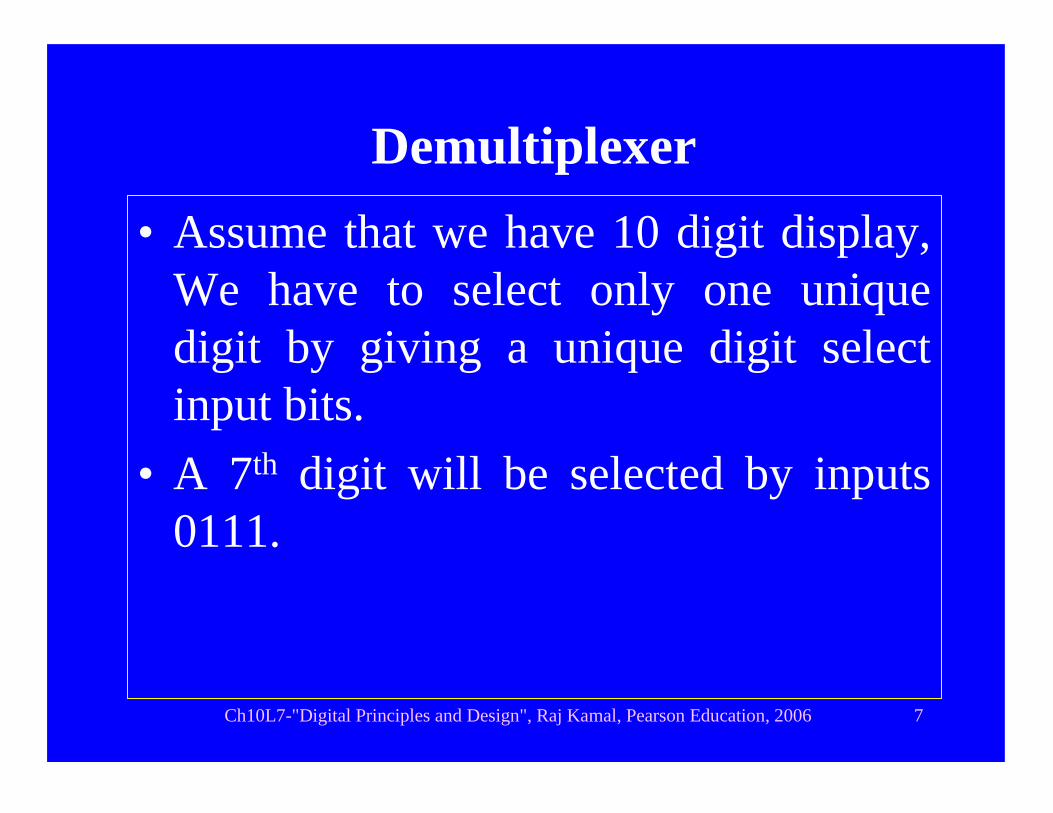
Demultiplexer• Assume that we have 10 digit display,
We have to select only one unique digit by giving a unique digit select input bits.
• A 7th digit will be selected by inputs 0111.

Ch10L7-"Digital Principles and Design", Raj Kamal, Pearson Education, 2006 8
1 to n Demultiplexer
• A circuit, which takes the n-bit channel or address select input, activates only one of the output out of 2n outputs and remaining remains inactive. That output equals the input. [Input is multiplexed and has data fro different channels at different instances. Inactive output can be taken as tristate or 1 or 0
• Active output be taken as 1 or 0
Ch10L7-"Digital Principles and Design", Raj Kamal, Pearson Education, 2006 9
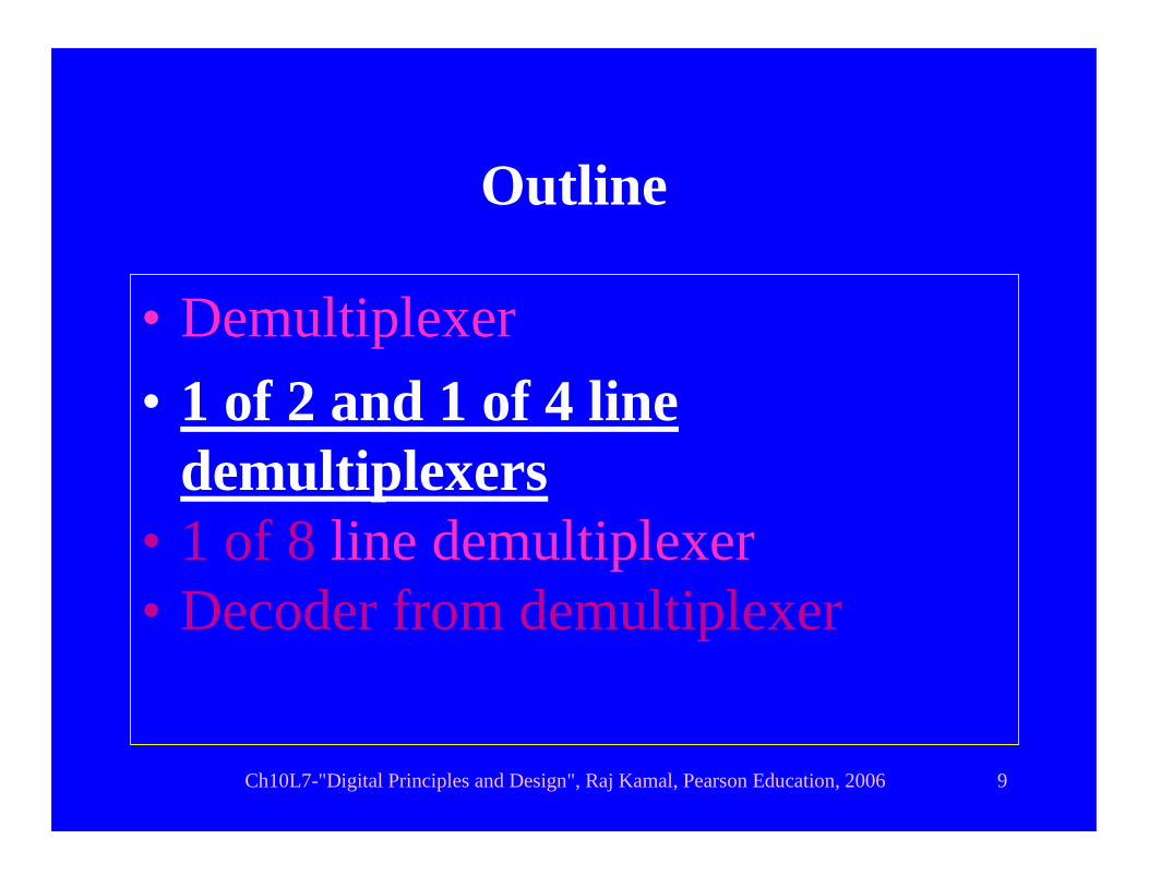
Outline
• Demultiplexer • 1 of 2 and 1 of 4 line
demultiplexers• 1 of 8 line demultiplexer• Decoder from demultiplexer

Ch10L7-"Digital Principles and Design", Raj Kamal, Pearson Education, 2006 10
1 of 2 Demultiplexer with inactive tristate output
F0 0 F0 *
Input Address-select input Outputs I A Y0 Y1
* means tristate or 1 or 0. F0 is a Boolean Function or logic circuit output
Y0Y1A
F0 1 * F0
IF0

Ch10L7-"Digital Principles and Design", Raj Kamal, Pearson Education, 2006 11
1 of 2 Demultiplexer with inactive 0 output
F0 = 1 0 1 0
Input Address-select input Outputs I A Y0 Y1
Y0Y1A
F0 = 1 1 0 1
I1

Ch10L7-"Digital Principles and Design", Raj Kamal, Pearson Education, 2006 12
1 of 2 Demultiplexer with inactive 1 output
F0 = 0 0 0 1
Input Address-select input Outputs I A Y0 Y1
Y0Y1A
F0 = 0 1 1 0
I0
Ch10L7-"Digital Principles and Design", Raj Kamal, Pearson Education, 2006 13
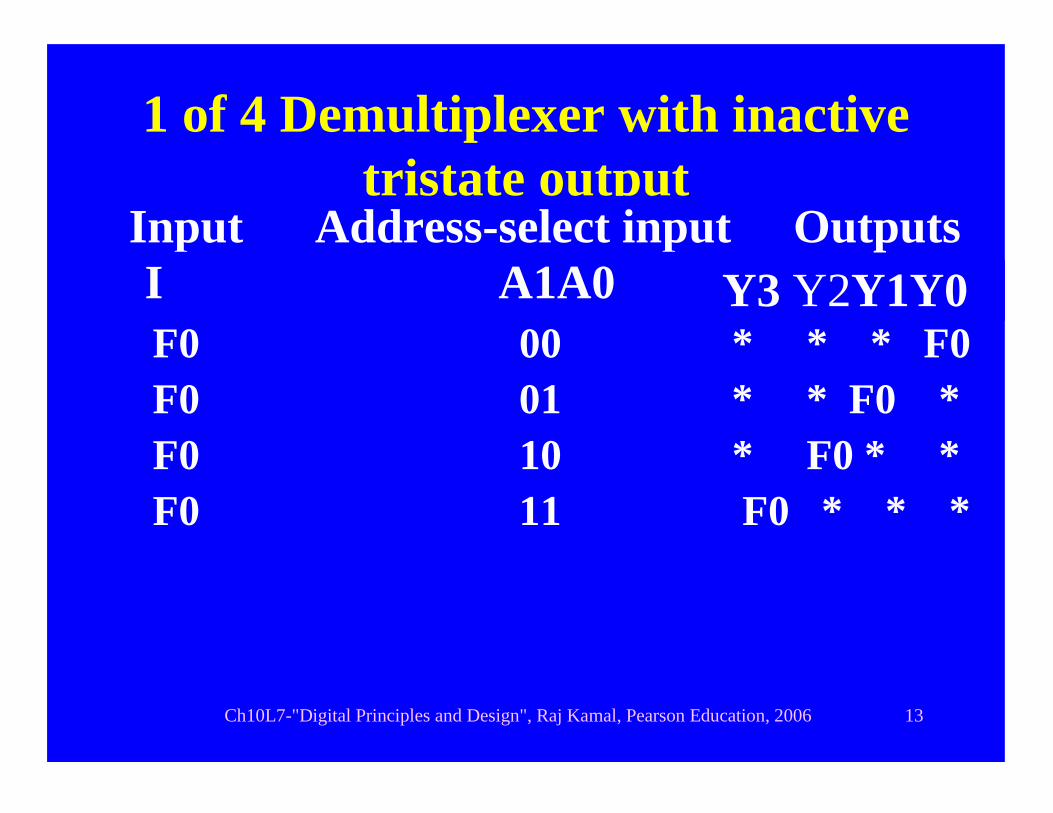
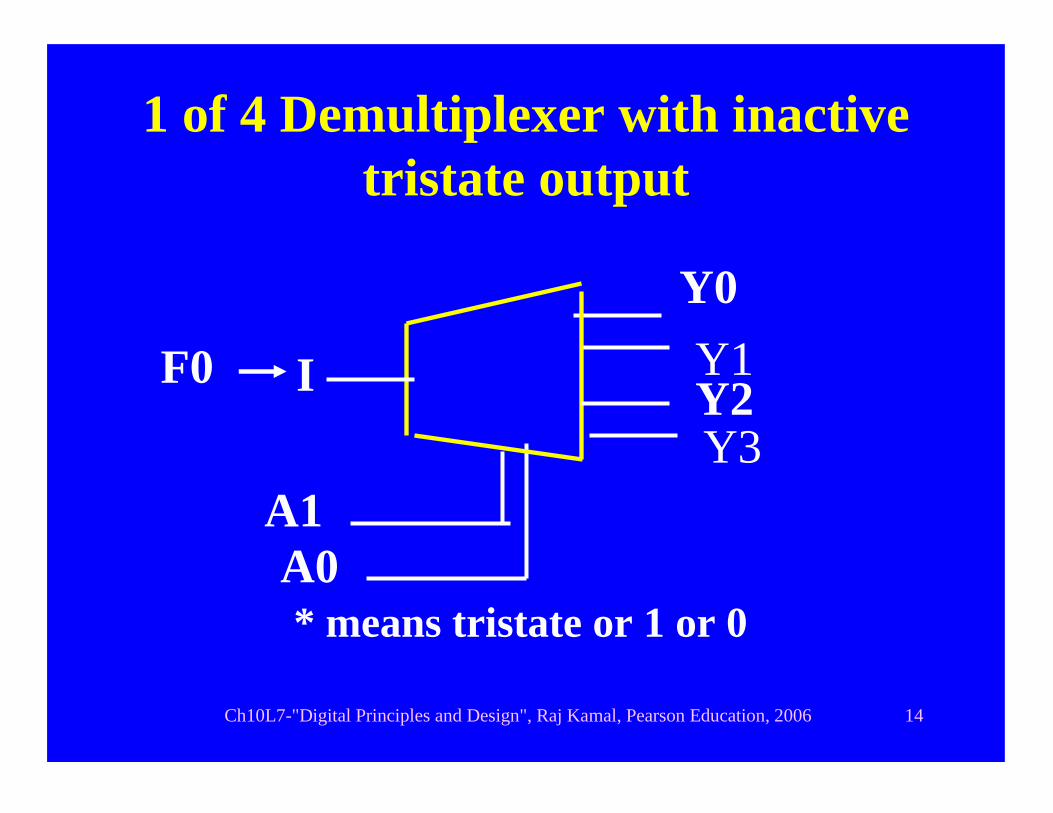
1 of 4 Demultiplexer with inactive tristate output
F0 00 * * * F0
Input Address-select input Outputs I A1A0 Y3 Y2Y1Y0
F0 01 * * F0 *F0 10 * F0 * *F0 11 F0 * * *
Ch10L7-"Digital Principles and Design", Raj Kamal, Pearson Education, 2006 14
1 of 4 Demultiplexer with inactive tristate output
* means tristate or 1 or 0
Y0Y1
A0
IF0Y2Y3
A1

Ch10L7-"Digital Principles and Design", Raj Kamal, Pearson Education, 2006 15
Outline
• Demultiplexer • 1 of 2 and 1 of 4 line
demultiplexers• 1 of 8 line demultiplexer• Decoder from demultiplexer

Ch10L7-"Digital Principles and Design", Raj Kamal, Pearson Education, 2006 16
1 of 8 Demultiplexer with inactive tristate output
* means tristate or 1 or 0
Y0Y1
A0
IF0Y2Y3
A1A2
Y4Y5
Y7Y6

Ch10L7-"Digital Principles and Design", Raj Kamal, Pearson Education, 2006 17
1 of 8 Demultiplexer with inactive output 1
Y0Y1
A0
I0Y2Y3
A1A2
Y4Y5
Y7Y6

Ch10L7-"Digital Principles and Design", Raj Kamal, Pearson Education, 2006 18
Outline
• Demultiplexer • 1 of 2 and 1 of 4 line
demultiplexers• 1 of 8 line demultiplexer• Decoder from demultiplexer

Ch10L7-"Digital Principles and Design", Raj Kamal, Pearson Education, 2006 19
Decoder from a 1 of 8 Demultiplexer with one control (enabling/disabling)
pin. Active 0 output
Y0
Y7
Address Select Input bits
G
I
Y1Y2
Y3Y4
Y5Y6
A0A1A2
0

Ch10L7-"Digital Principles and Design", Raj Kamal, Pearson Education, 2006 20
Summary

Ch10L7-"Digital Principles and Design", Raj Kamal, Pearson Education, 2006 21
Demultiplexer
• Demultiplexer active one output pin among 2n output pins and has n address or channel select inputs to enable circuit to select corresponding output.

Ch10L7-"Digital Principles and Design", Raj Kamal, Pearson Education, 2006 22
Demultiplexer
• A demultiplexer can have inactive outputs in tristate and active output as 0 or 1
• A demultiplexer can have control gate pins
• A demultiplexer function as decoder with active 1 or 0 as per input pin

Ch10L7-"Digital Principles and Design", Raj Kamal, Pearson Education, 2006 23
End of Lesson 7 on
Demultiplexer

Ch10L7-"Digital Principles and Design", Raj Kamal, Pearson Education, 2006 24
THANK YOU


![Etu02 Mux Man[1]](https://img.pdfslide.us/doc/110x75/5436e8ae219acd5b118b477c/etu02-mux-man1.jpg)