Embed Size (px)
Citation preview
Submitted By:A.Pradeep
(11B71A0244)
Seminar Title
DETECTING POWER GRID SYNCHRONISATION FAILURE ON SENSING
BAD VOLTAGE OR FREQUENCY

ABSTRACTThis paper presents the development of a microcontroller based
islanding detection for grid connected inverter with very simple
under/over voltage and under/over frequency islanding detection
algorithms.
The microcontroller monitors the under/over voltage and under/over
frequency from utility grid and the processed value of voltage and
frequency for turning ON/OFF the relay between a grid connected
inverter and the utility grid.
The project would alternatively use a variable frequency generator
using 555timer for changing the frequency while a standard variac
shall be used to vary the input voltage for achieving the test
conditions as stated above.

HARDWARE REQUIREMENTS
POWER SUPPLY BLOCK
MICROCONTROLLER (AT89S52/AT89C51)
555 TIMER
LM358
LM339
RELAYS
BC547(NPN TRANSISTOR)
LIQUID CRYSTAL DISPLAY
LED
IN4007
RESISTORS
CAPACITORS

POWER SUPPLY
230 V AC 50 Hz
5VDC
230/12V step down transformer
Filter(470µf)
5v RegulatorBridge rectifier

MICROCONTROLLER
• It is a smaller computer
• Has on-chip RAM, ROM, I/O ports...
Pin Description

555 TIMERThe 555 Timer IC is an integrated circuit (chip) implementing a variety of timer and multivibrator applications
The 555 has three operating modes:
•Monostable mode: in this mode, the 555 functions as a "one-
shot". Applications include timers, missing pulse detection,
switches, touch switches, frequency divider, capacitance
measurement, pulse-width modulation (PWM) etc.
•Astable - free running mode: the 555 can operate as an
oscillator. Uses include LED and lamp flashers, pulse
generation, logic clocks, tone generation, security alarms,
pulse position modulation, etc.
•Bistable mode or Schmitt trigger: the 555 can operate as a
flip-flop, if the DIS pin is not connected and no capacitor is
used. Uses include bounce free latched switches, etc.
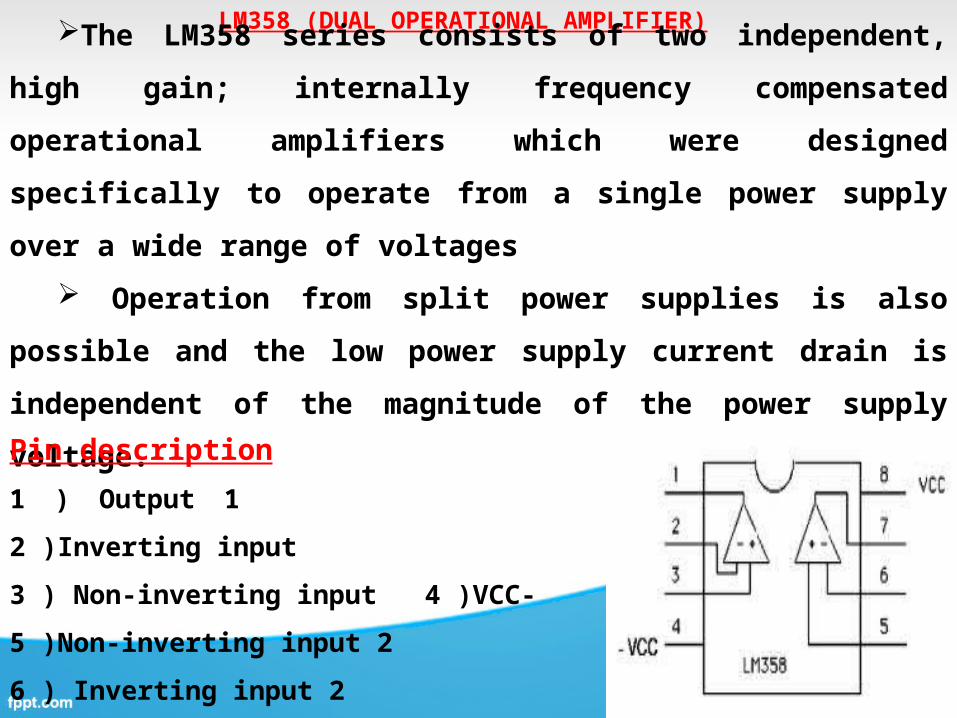
LM358 (DUAL OPERATIONAL AMPLIFIER)
The LM358 series consists of two independent, high gain; internally
frequency compensated operational amplifiers which were designed
specifically to operate from a single power supply over a wide range of
voltages
Operation from split power supplies is also possible and the low
power supply current drain is independent of the magnitude of the power
supply voltage.
Pin description
1 ) Output 1 2 )Inverting input
3 ) Non-inverting input 4 )VCC-
5 )Non-inverting input 2
6 ) Inverting input 2
7 ) Output 2 8 ) VCC+

LM339( COMPARATOR)
The LM339 consists of four independent precision voltage comparators.
The LM339 series was designed to
directly interface with TTL and CMOS.
When operated from both plus and
minus power supplies, the LM339 series
will directly interface with MOS logic
where their low power drain is a distinct
advantage over standard comparators.

RELAY
IT IS A ELECTRO MAGNETIC SWITCH
USED TO CONTROL THE ELECTRICAL DEVICES
COPPER CORE MAGNETIC FLUX PLAYS MAIN ROLE HERE
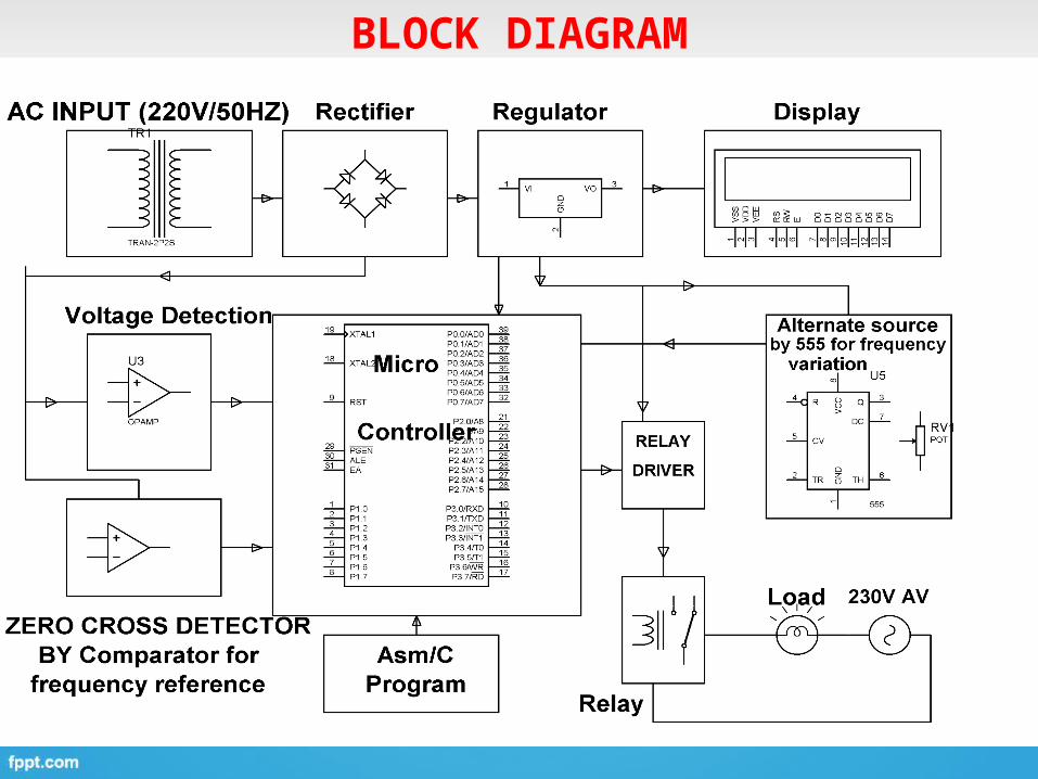
BLOCK DIAGRAM

Islanding of grid is connected to inverter which is basically managing two
parameters voltage and frequency
In the program it is so written that the output from 555 timer which is fed to
the MC goes to be low 48KHz or above 52Hz. The corresponding outputs of MC
will go high and which will result in switching “ON or OFF” a load to indicate
that the islanding has taken place. (for frequency concerned).
As per the voltage is concerned we have taken 2 comparators. Both the
comparators are given to i.e., one for inverting input and other for non-
inverting input which are given at a particular voltage.
This program is that in either of these cases whether the few is low / high (or)
it could be either in high / low condition the duration will be 50, 49, 48 06
greater than 52.
Working of project
Advantages
The advantage of this project is, it’s secured the Power of the Grid i.e., Power Plants should supply power to the grid rather than drawing the power from the grid.

DISADVANTAGE
The disadvantage of this project is, it’s available in
single phase supply where power Grid is of Three
Phase supply.

Applications
This project is applicable for Solar Power Plant
where frequency varies; frequency and voltage
parameters should match with the Power grid.

THANK YOU