Embed Size (px)
Citation preview
D.C. CircuitsCurrent and Potential Difference in Circuits
Series and Parallel Circuits

Current and Potential Difference in
Circuits
Draw circuit diagrams with power sources (cell, battery or a.c. mains), switches (closed and open), resistors (fixed and variable), light-dependent resistors, thermistors, lamps, ammeters, voltmeters, magnetising coils, bells, fuses, relays, diodes and light-emitting diodes.

Electric Ciruit An electric circuit is a complete or closed path through which
charge can flow from one terminal of an electrical source to
the other.
It consists of four main parts or components:
One that drives the electric charge round the circuit, e.g. a
battery;
One on which the moving charge can do a useful job, e.g. a
lamp;
Conductors to join them together, e.g. copper wire;
Switches to break or complete the circuit.

Symbols in Drawing Circuit
a.c. supplycell battery d.c. supply
open switch
lamp
resistor variable resistor
light dependent
resistor (LDR)thermistor
closed switch
ammeter
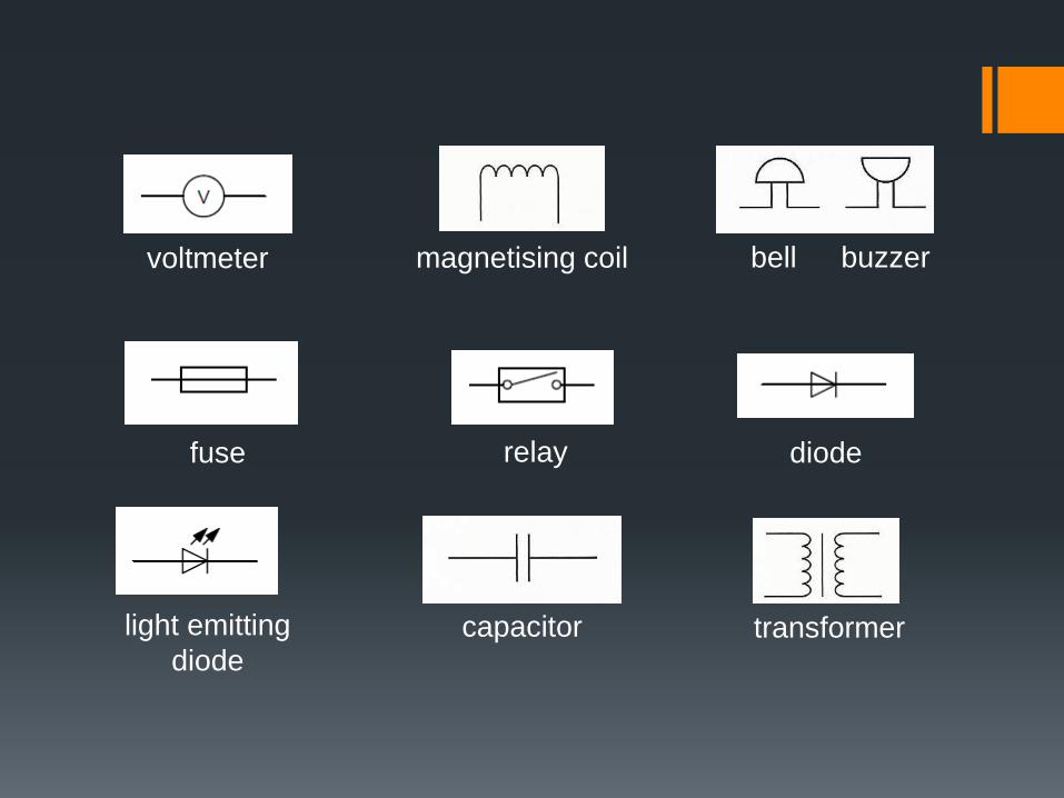
fuse
capacitor
bell buzzermagnetising coil
transformer
diode
voltmeter
relay
light emitting
diode

Current and Potential Difference in
Circuits
State that the current at every point in a series circuit is the
same, and use this in calculations.
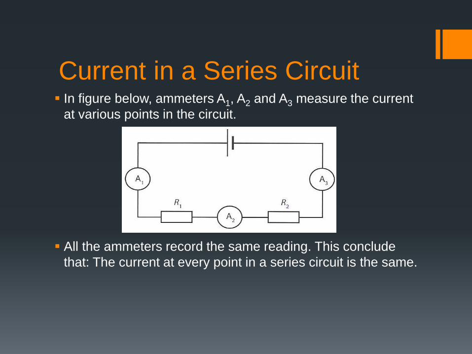
Current in a Series Circuit In figure below, ammeters A1, A2 and A3 measure the current
at various points in the circuit.
All the ammeters record the same reading. This conclude
that: The current at every point in a series circuit is the same.

Current and Potential Difference in
Circuits
State that the sum of the potential differences in a series circuit
is equal to the potential difference across the whole circuit and
use this in calculations.

Potential Difference in a Series
Circuit In figure below, voltmeters V1 and V2 measure the potential
differences across R1 and R2 respectively. Voltmeter V
measures the potential difference across the whole circuit.
The sum of the potential differences in a series circuit is
equal to the potential difference across the whole circuit, i.e.
V = V1 + V2.
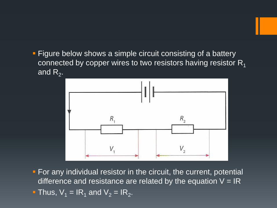
Figure below shows a simple circuit consisting of a battery
connected by copper wires to two resistors having resistor R1
and R2.
For any individual resistor in the circuit, the current, potential
difference and resistance are related by the equation V = IR
Thus, V1 = IR1 and V2 = IR2.
In a series circuit, the component with largest resistance has
the highest potential difference across it.
If the internal resistance of cell is neglected, the e.m.f. E of
the cell equals to the potential difference across the whole
circuit V.
In series circuit, the current will cease to flow if there is a
break anywhere in the circuit.
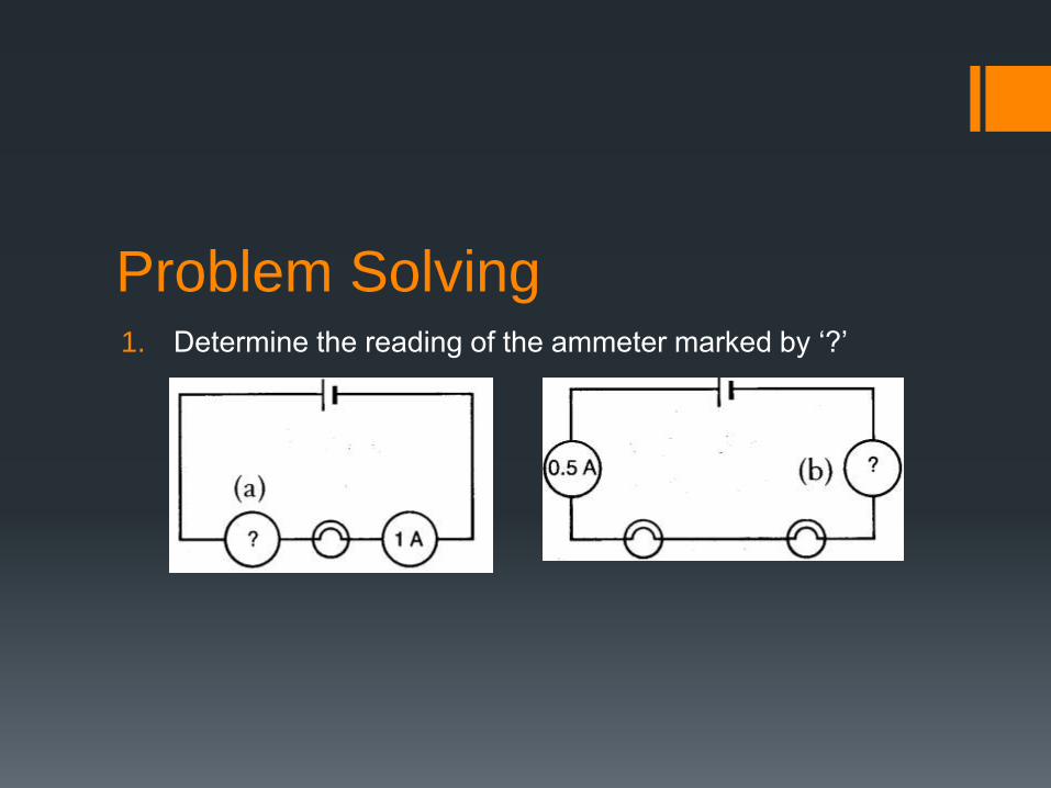
Problem Solving 1. Determine the reading of the ammeter marked by ‘?’
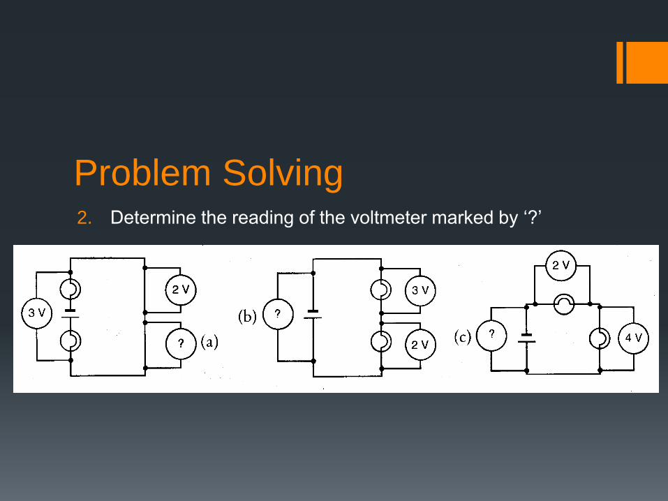
Problem Solving2. Determine the reading of the voltmeter marked by ‘?’

3. Two resistors valued 30 Ω and 15 Ω are connected in
series.
a. Calculate its effective resistance.
b. Calculate the current which a 4.5 V battery supplies to each
combination.
c. Calculate the potential difference across each separate resistor
when the 4.5 V battery is connected across each combination.
Problem Solving

4. In a circuit four resistors valued 8 Ω, 20 Ω, 24 Ω and 30 Ω
are connected in series to a 60 V cell. Find
a. The combined resistance,
b. The current ,
c. The potential difference across the 20 Ω resistor.
Problem Solving

5. Three resistors are connected in series to a 24 V battery,
and an ammeter in the circuit reads 0.5 A. The first resistor
is rated at 22 Ω, and the second at 8 Ω. Find
a. The total resistance,
b. The resistance of the third resistor,
c. The potential difference across the third resistor.
Problem Solving

Current and Potential Difference in
Circuits
State that the current from the source is the sum of the currents
in the separate branches of a parallel circuit.
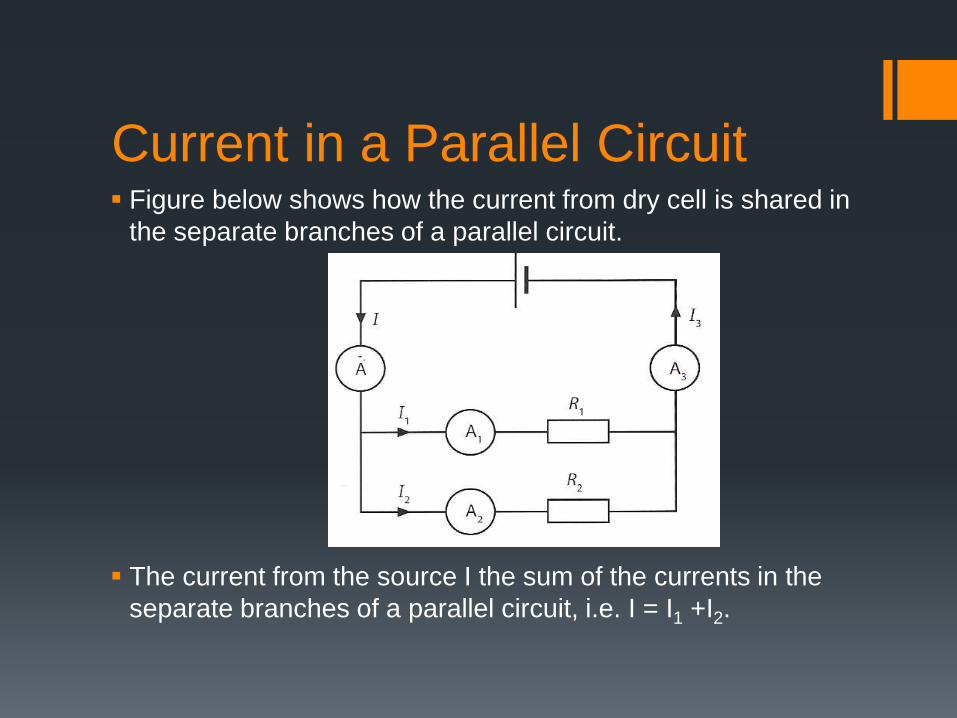
Current in a Parallel Circuit Figure below shows how the current from dry cell is shared in
the separate branches of a parallel circuit.
The current from the source I the sum of the currents in the
separate branches of a parallel circuit, i.e. I = I1 +I2.
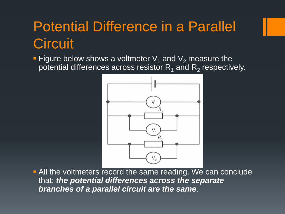
Potential Difference in a Parallel
Circuit Figure below shows a voltmeter V1 and V2 measure the
potential differences across resistor R1 and R2 respectively.
All the voltmeters record the same reading. We can conclude that: the potential differences across the separate branches of a parallel circuit are the same.

In parallel circuit, the component with the smallest resistance
has the highest current flowing through it.
The current flowing out from the cell, I, is the same as the
current flowing back to the cell, I3.
Any breakdown in one of the parallel branches does not
affect the current flow in the other branches of the circuit.
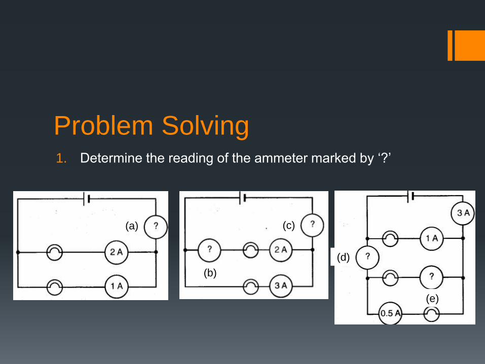
Problem Solving 1. Determine the reading of the ammeter marked by ‘?’
(a)
(b)
(c)
(d)
(e)
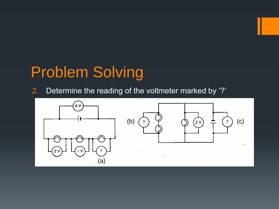
Problem Solving 2. Determine the reading of the voltmeter marked by ‘?’
(a)
(b) (c)
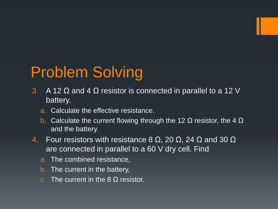
Problem Solving3. A 12 Ω and 4 Ω resistor is connected in parallel to a 12 V
battery.
a. Calculate the effective resistance.
b. Calculate the current flowing through the 12 Ω resistor, the 4 Ω
and the battery.
4. Four resistors with resistance 8 Ω, 20 Ω, 24 Ω and 30 Ω
are connected in parallel to a 60 V dry cell. Find
a. The combined resistance,
b. The current in the battery,
c. The current in the 8 Ω resistor.

Series and Parallel Circuits
Do calculations on the whole circuit, recalling and using
formulae including R = V/ I and those for potential differences
in series, resistors in series and resistors in parallel.
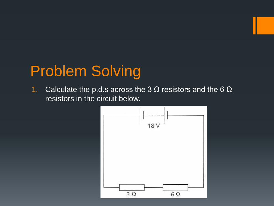
Problem Solving 1. Calculate the p.d.s across the 3 Ω resistors and the 6 Ω
resistors in the circuit below.

Problem Solving2. Calculate the currents I, I2 and I3 in the circuit below.
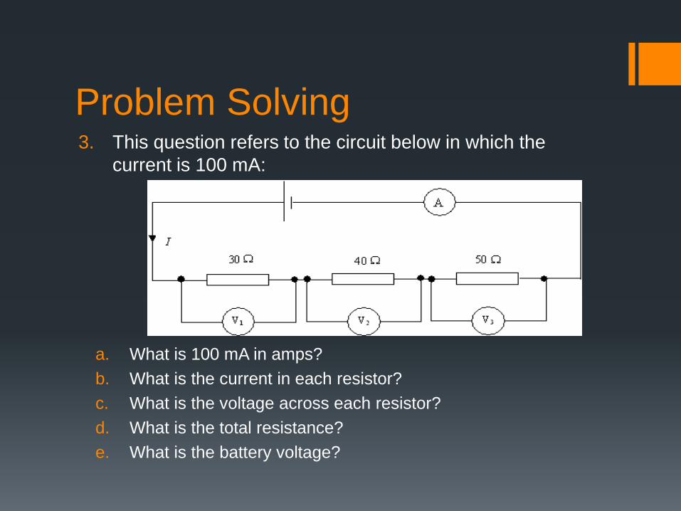
Problem Solving 3. This question refers to the circuit below in which the
current is 100 mA:
a. What is 100 mA in amps?
b. What is the current in each resistor?
c. What is the voltage across each resistor?
d. What is the total resistance?
e. What is the battery voltage?
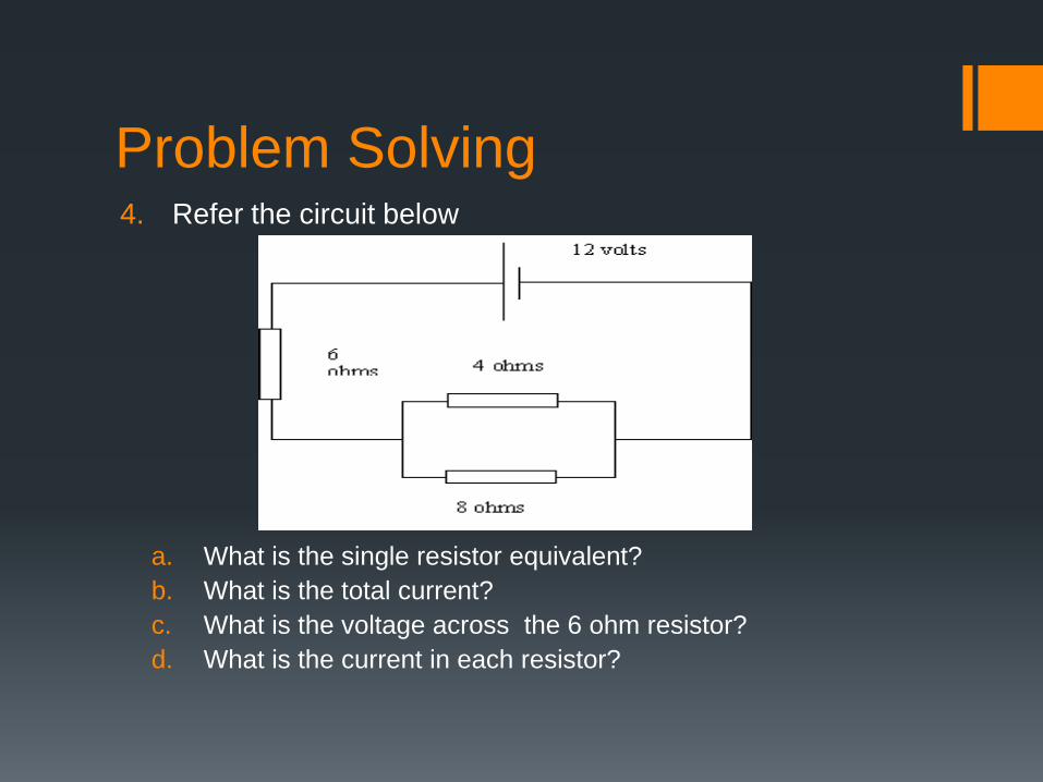
Problem Solving4. Refer the circuit below
a. What is the single resistor equivalent?
b. What is the total current?
c. What is the voltage across the 6 ohm resistor?
d. What is the current in each resistor?
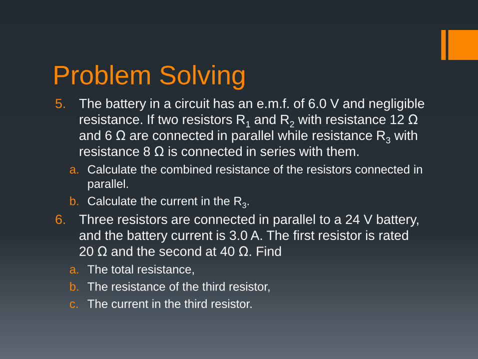
Problem Solving5. The battery in a circuit has an e.m.f. of 6.0 V and negligible
resistance. If two resistors R1 and R2 with resistance 12 Ω
and 6 Ω are connected in parallel while resistance R3 with
resistance 8 Ω is connected in series with them.
a. Calculate the combined resistance of the resistors connected in
parallel.
b. Calculate the current in the R3.
6. Three resistors are connected in parallel to a 24 V battery,
and the battery current is 3.0 A. The first resistor is rated
20 Ω and the second at 40 Ω. Find
a. The total resistance,
b. The resistance of the third resistor,
c. The current in the third resistor.
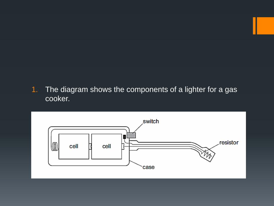
1. The diagram shows the components of a lighter for a gas
cooker.

1. Which circuit diagram is correct for this lighter?
A
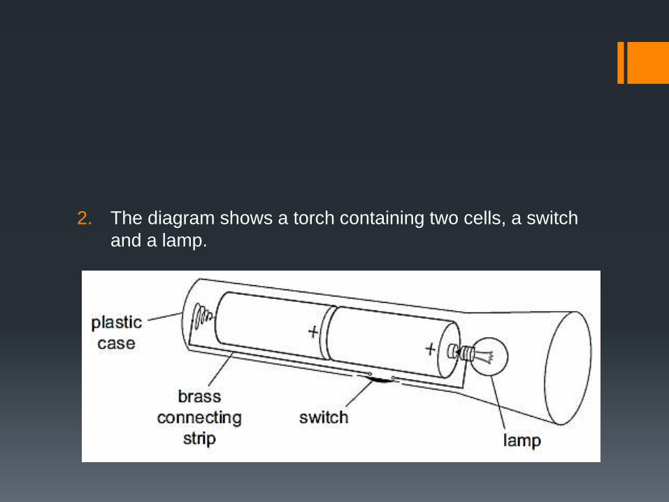
2. The diagram shows a torch containing two cells, a switch
and a lamp.
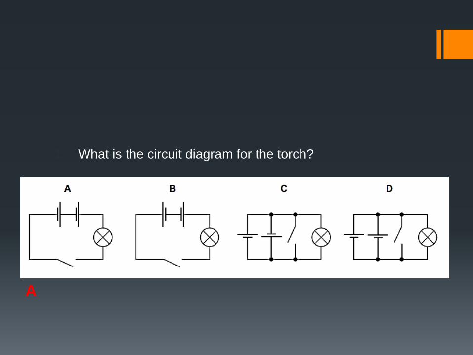
1. What is the circuit diagram for the torch?
A
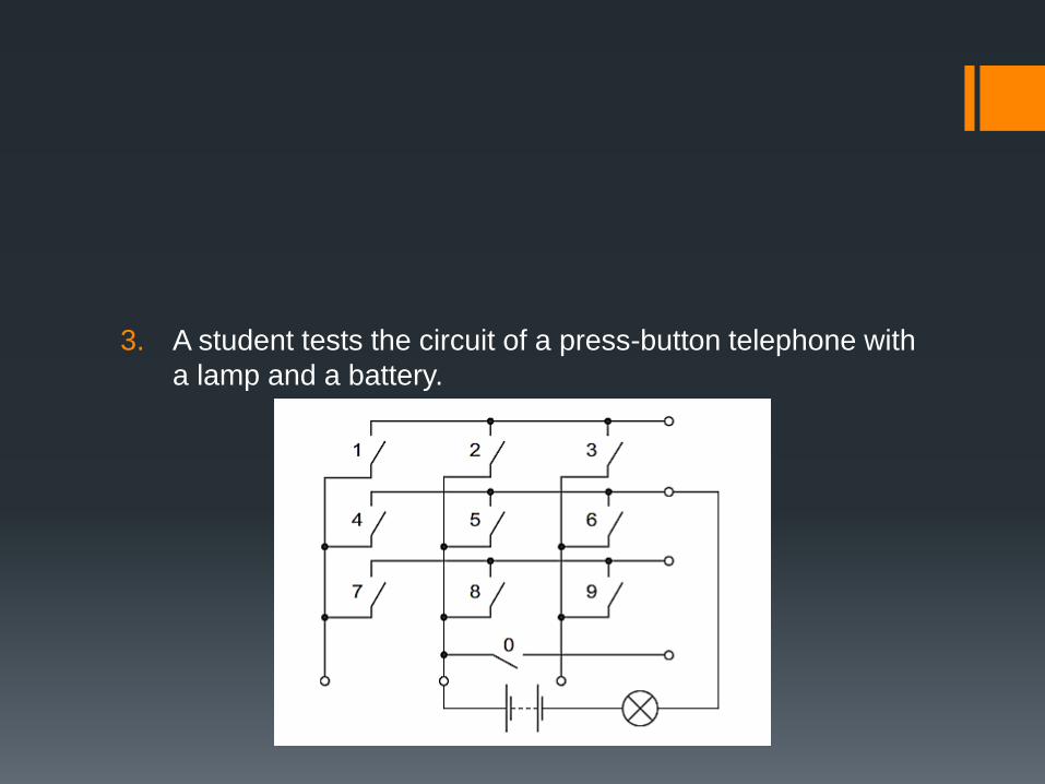
3. A student tests the circuit of a press-button telephone with
a lamp and a battery.
1. Which single switch can be pressed to make the lamp
light?
A. 0
B. 1
C. 5
D. 6
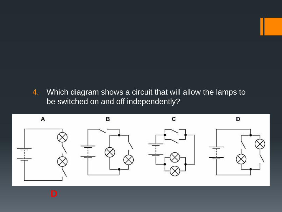
4. Which diagram shows a circuit that will allow the lamps to
be switched on and off independently?
D
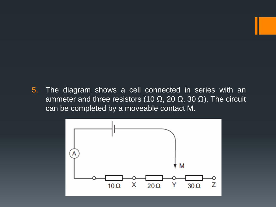
5. The diagram shows a cell connected in series with an
ammeter and three resistors (10 Ω, 20 Ω, 30 Ω). The circuit
can be completed by a moveable contact M.

1. When M is connected to X, the ammeter reads 0.6 A.
2. What is the ammeter reading when M is connected to Y?
A. 0.1 A
B. 0.2 A
C. 0.3 A
D. 0.6 A
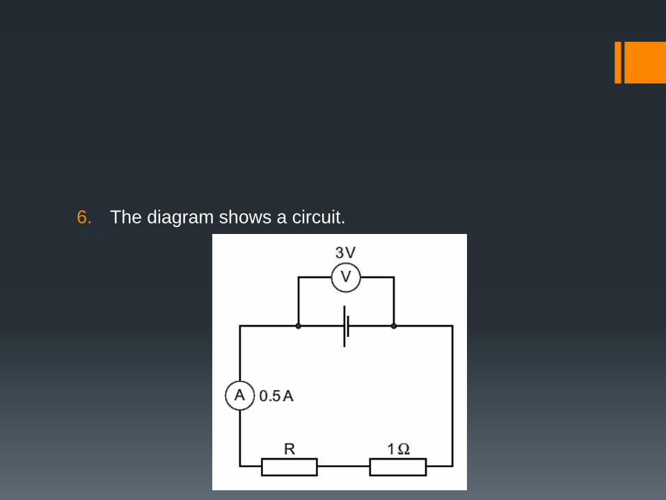
6. The diagram shows a circuit.
1. The ammeter has negligible resistance.
2. What is the resistance of the resistor R?
A. 0.5 Ω
B. 1.5 Ω
C. 5 Ω
D. 6 Ω

7. In the circuit shown, ammeter X reads 0.5 A.

1. What does ammeter Y read?
A. 0
B. 0.5 A
C. 3.5 A
D. 4.0 A
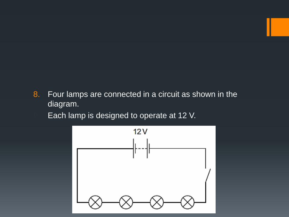
8. Four lamps are connected in a circuit as shown in the
diagram.
9. Each lamp is designed to operate at 12 V.
1. The circuit is now switched on.
2. Which statement is correct?
A. Each lamp can be switched off independently.
B. If one lamp breaks all the others will stay alight.
C. The current is the same in all the lamps.
D. The lamps will all light at normal brightness.
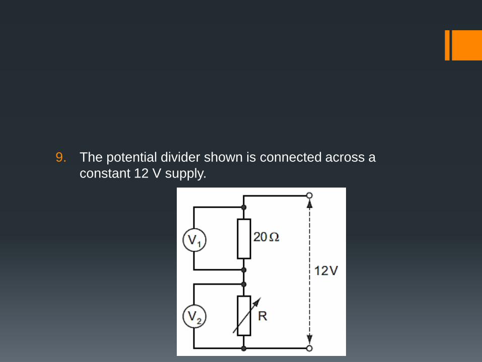
9. The potential divider shown is connected across a
constant 12 V supply.
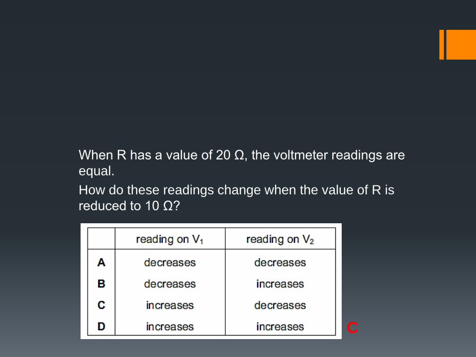
1. When R has a value of 20 Ω, the voltmeter readings are
equal.
2. How do these readings change when the value of R is
reduced to 10 Ω?
C
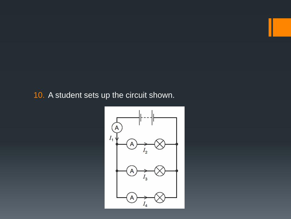
10. A student sets up the circuit shown.
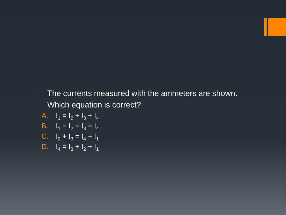
1. The currents measured with the ammeters are shown.
2. Which equation is correct?
A. I1 = I2 + I3 + I4
B. I1 = I2 = I3 = I4
C. I2 + I3 = I4 + I1
D. I4 = I3 + I2 + I1
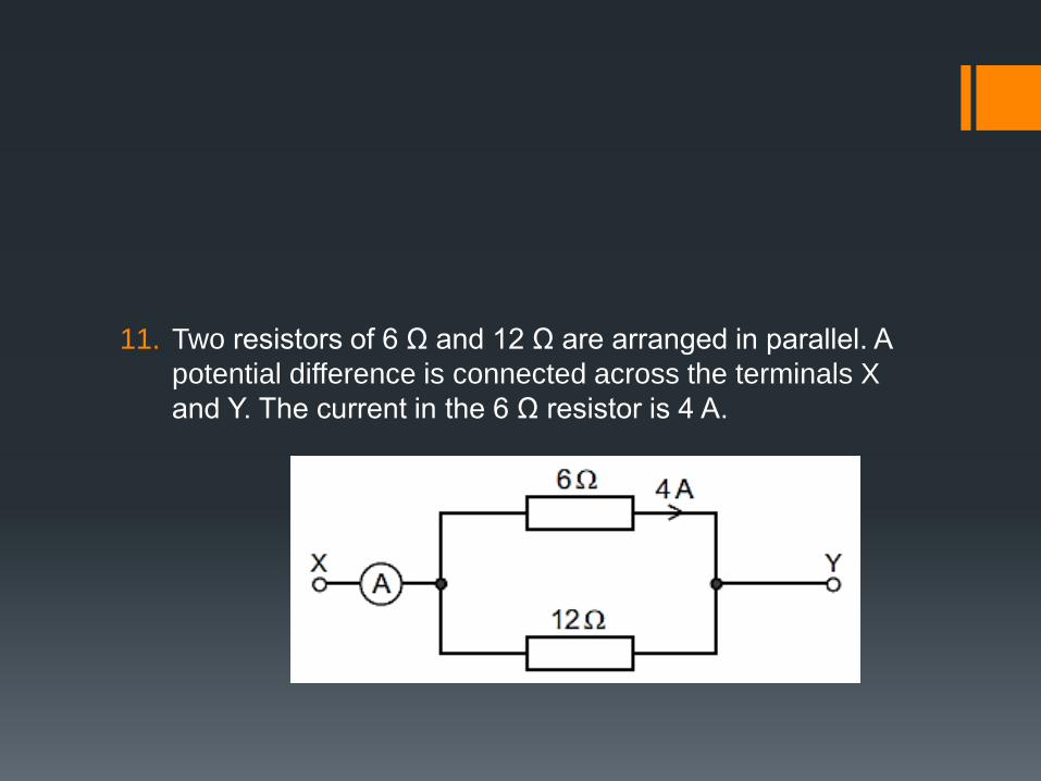
11. Two resistors of 6 Ω and 12 Ω are arranged in parallel. A
potential difference is connected across the terminals X
and Y. The current in the 6 Ω resistor is 4 A.
1. What is the current in the ammeter?
A. 4 A
B. 6 A
C. 8 A
D. 12 A

12. In the circuit shown, the switches S1 and S2 may be open
(off) or closed (on).
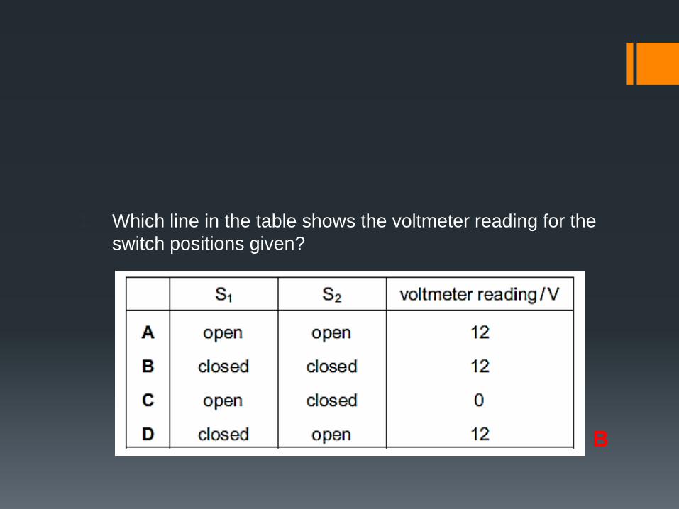
1. Which line in the table shows the voltmeter reading for the
switch positions given?
B
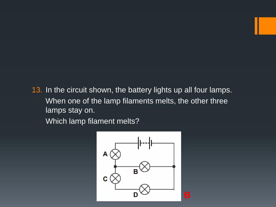
13. In the circuit shown, the battery lights up all four lamps.
14. When one of the lamp filaments melts, the other three
lamps stay on.
15. Which lamp filament melts?
B

14. In the circuit below, one of the lamps breaks, causing all
the other lamps to go out.
15. Which lamp breaks?
D
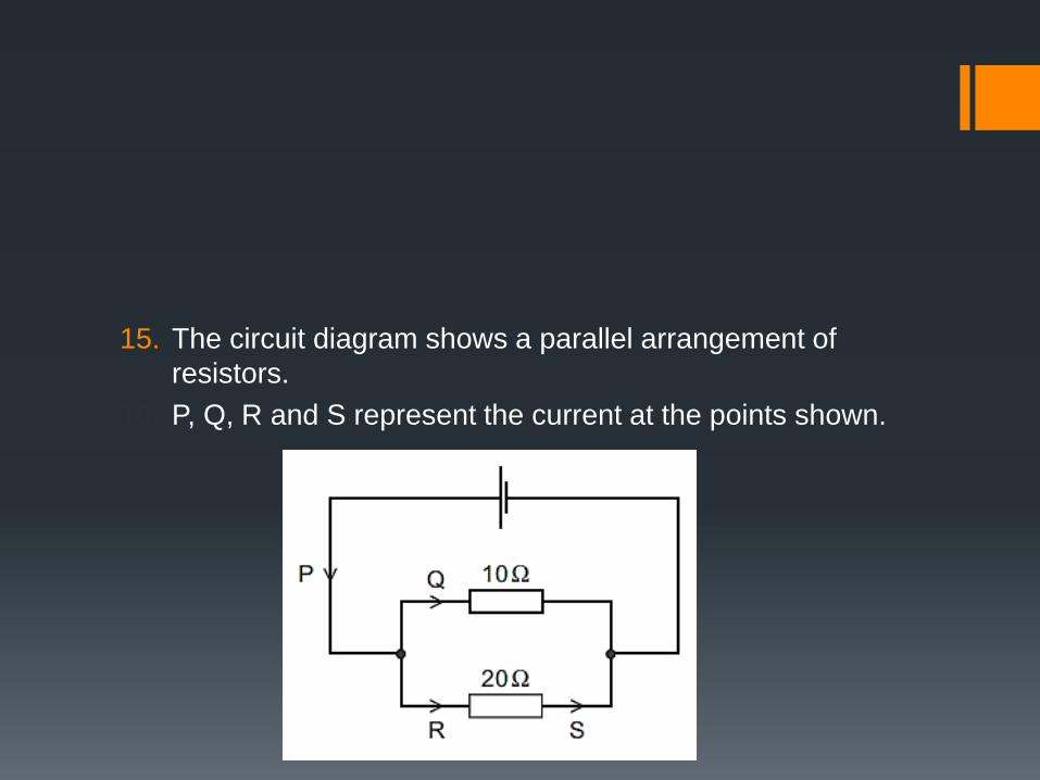
15. The circuit diagram shows a parallel arrangement of
resistors.
16. P, Q, R and S represent the current at the points shown.
1. Which statement is correct?
A. P is greater than Q.
B. Q is equal to R.
C. R is greater than S.
D. S is equal to P.
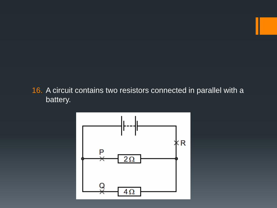
16. A circuit contains two resistors connected in parallel with a
battery.
1. Which of the following statements about the currents at P,
Q and R is true?
A. The current at P is the greatest.
B. The current at Q is the greatest.
C. The current at R is the greatest.
D. The current is the same at points P, Q and R.
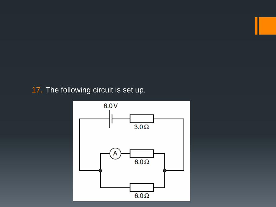
17. The following circuit is set up.

1. What is the reading on the ammeter?
A. 0.33 A
B. 0.50 A
C. 0.67 A
D. 1.0 A
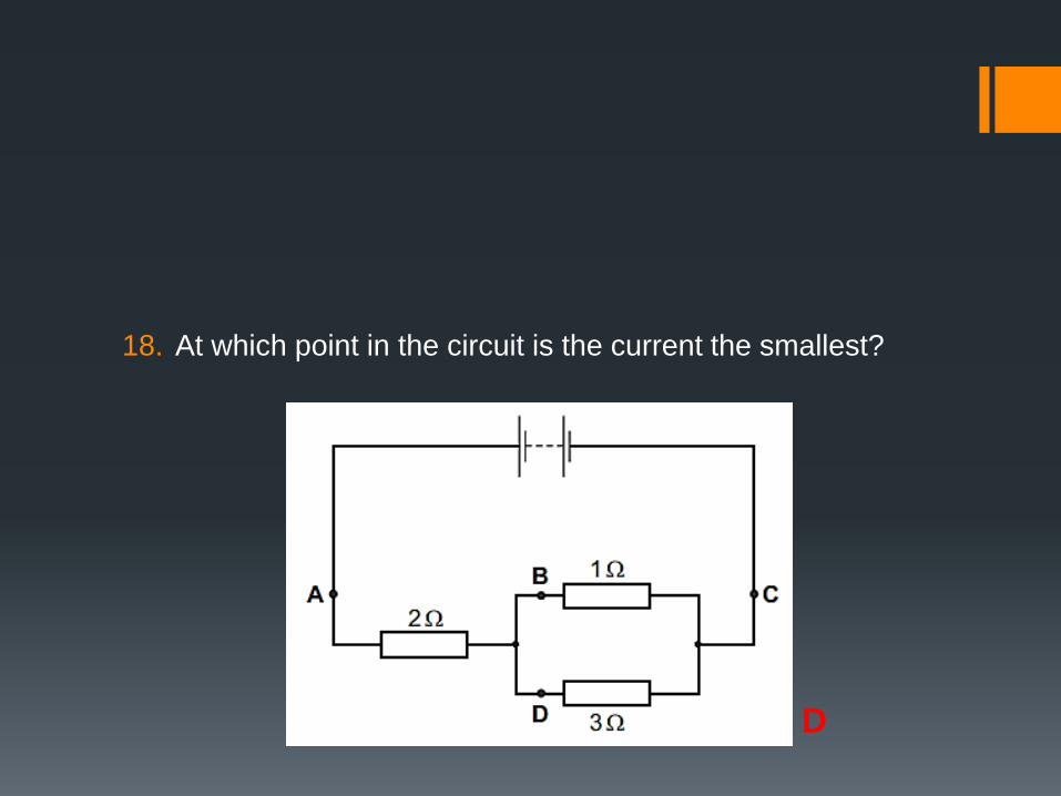
18. At which point in the circuit is the current the smallest?
D
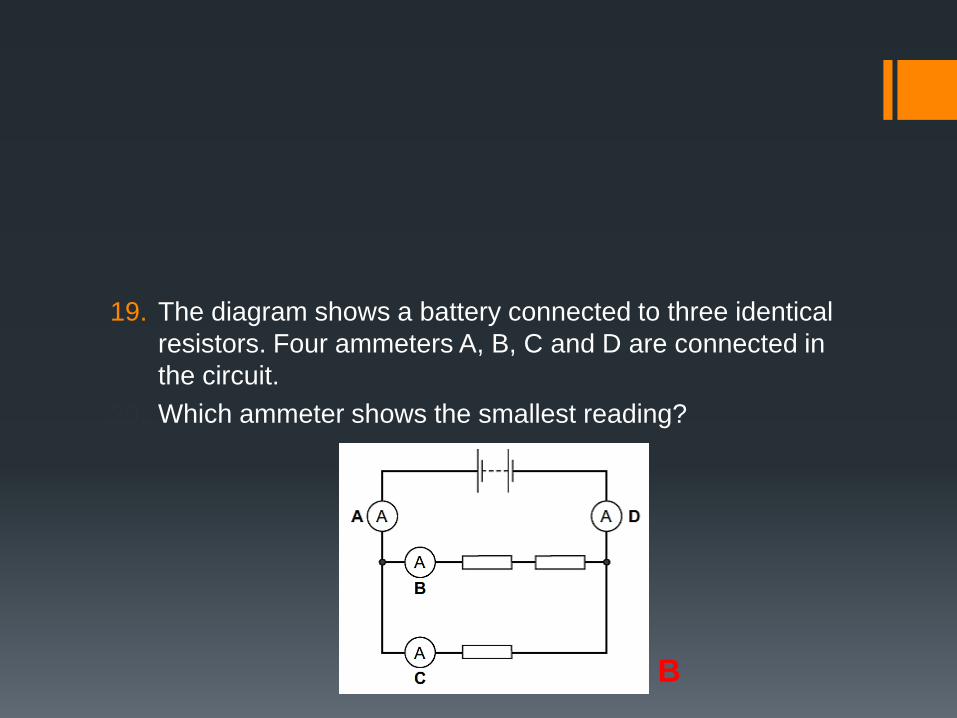
19. The diagram shows a battery connected to three identical
resistors. Four ammeters A, B, C and D are connected in
the circuit.
20. Which ammeter shows the smallest reading?
B