Embed Size (px)
Citation preview
Tutorial On CRO (Cathode Ray Oscilloscope) Working
and Applications
http://www.elprocus.com/
Tutorial On CRO (Cathode Ray Oscilloscope) Working and
ApplicationsIntroduction:
The CRO stands for a cathode ray oscilloscope. In modern electronics, the CRO plays an important role in the electronic circuits. It is typically divided into four sections which are display, vertical controllers, horizontal controllers, and Triggers. Most of the oscilloscopes are used the probes and they are used for the input of any instrument. We can analyze the waveform by plotting amplitude along with the x-axis and y-axis.
http://www.elprocus.com/
Tutorial On CRO (Cathode Ray Oscilloscope) Working and
Applications
The cathode ray oscilloscope is an electronic test instrument.
It is used to obtain waveforms when the different input signals are given.
In the early days, it is called as an Oscillograph.
The oscilloscope observes the changes in the electrical signals over time.
What Is A CRO
http://www.elprocus.com/
Tutorial On CRO (Cathode Ray Oscilloscope) Working and
ApplicationsWhat Is A CRO
Thus the voltage and time describe a shape and it is continuously graphed beside a scale.
By seeing the waveform, we can analyze some properties like amplitude, frequency, rise time, distortion, time interval and etc.
http://www.elprocus.com/
Tutorial On CRO (Cathode Ray Oscilloscope) Working and
ApplicationsWhat is a CRO
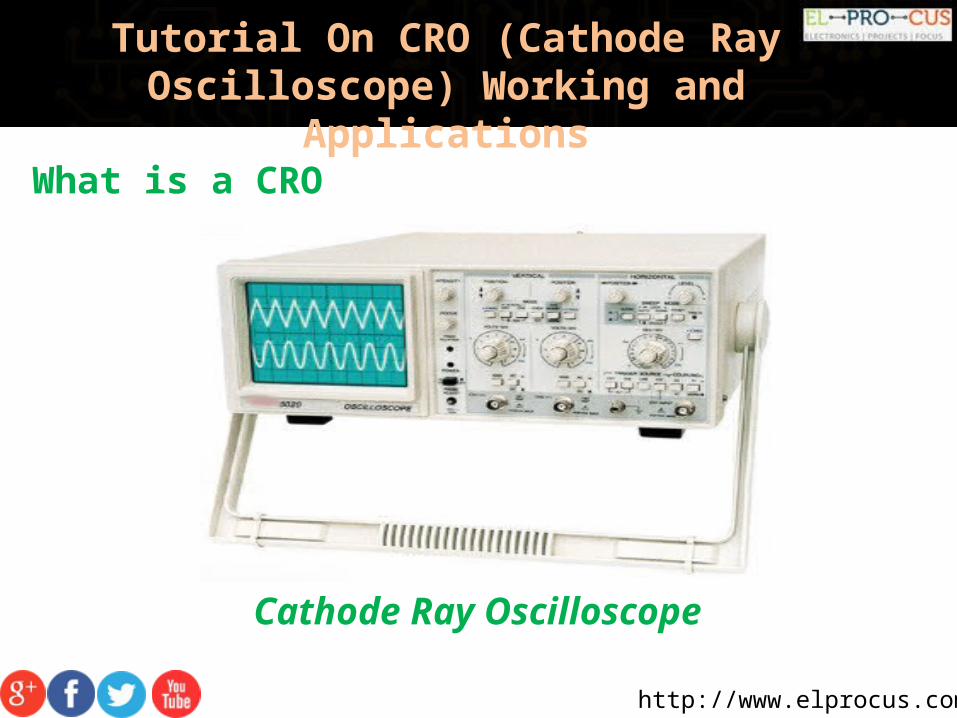
Cathode Ray Oscilloscope
http://www.elprocus.com/
Tutorial On CRO (Cathode Ray Oscilloscope) Working and
ApplicationsBlock Diagram of CRO
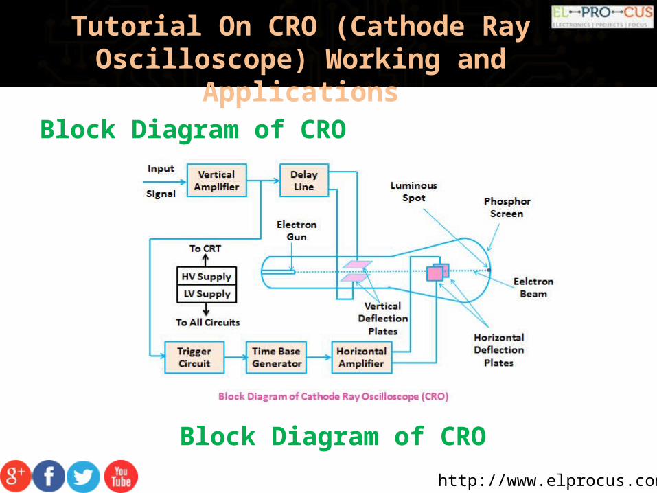
Block Diagram of CRO
http://www.elprocus.com/
Tutorial On CRO (Cathode Ray Oscilloscope) Working and
ApplicationsBlock Diagram of CRO
The CRO recruit the cathode ray tube and acts as a heat of the oscilloscope.
In an oscilloscope, the CRT produces the electron beam which is accelerated to a high velocity.
It brings to the focal point on a fluorescent screen.
http://www.elprocus.com/
Tutorial On CRO (Cathode Ray Oscilloscope) Working and
ApplicationsBlock Diagram of CRO
Thus, the screen produces a visible spot where the electron beam strikes with it.
By detecting the beam above the screen in reply to the electrical signal.
The electrons can act as an electrical pencil of light which produces a light where it strikes.
http://www.elprocus.com/
Tutorial On CRO (Cathode Ray Oscilloscope) Working and
ApplicationsBlock Diagram of CRO
To complete this task we need various electrical signals and voltages.
This provides the power supply circuit of the oscilloscope.
Here we will use high voltage and low voltage.
The low voltage is used for the heater of the electron gun to generate the electron beam.
The high voltage is required for the cathode ray tube to speed up the beam.
http://www.elprocus.com/
Tutorial On CRO (Cathode Ray Oscilloscope) Working and
Applications
The normal voltage supply is necessary for other control units of the oscilloscope.
The horizontal and vertical plates are placed between the electron gun and the screen.
Thus it can detect the beam according to the input signal.
Just before detecting the electron beam on the screen in the horizontal direction which is in X-axis a constant time-dependent rate, a time base generator is given by the oscillator.
Block Diagram of CRO
http://www.elprocus.com/
Tutorial On CRO (Cathode Ray Oscilloscope) Working and
ApplicationsBlock Diagram of CRO
The signals are passed from the vertical deflection plate through the vertical amplifier.
Thus, it can amplify the signal to a level will be provided the deflection of the electron beam.
If the electron beam is detected in the X-axis and the Y- axis a trigger circuit is given for the synchronizing these two types detections.
Hence the horizontal deflection starts at the same point of the input signal.
http://www.elprocus.com/
Tutorial On CRO (Cathode Ray Oscilloscope) Working and
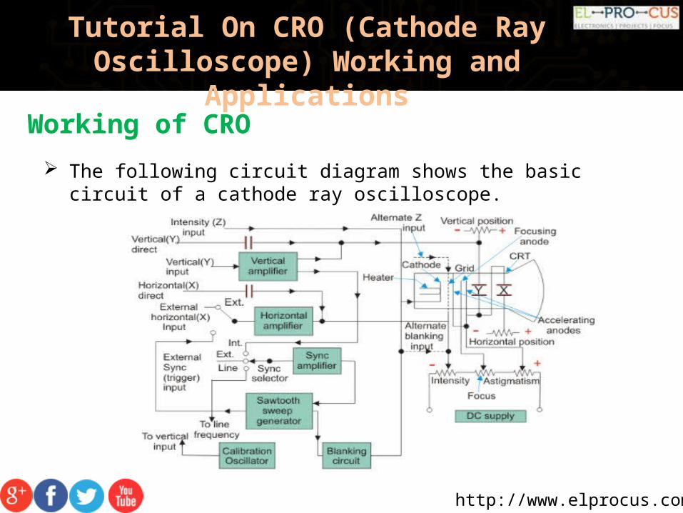
ApplicationsWorking of CRO The following circuit diagram shows the basic circuit of a cathode ray
oscilloscope.
http://www.elprocus.com/
Tutorial On CRO (Cathode Ray Oscilloscope) Working and
Applications
Vertical Deflection System
The main function of this amplifier is to amplify the weak signal.
so that the amplified signal can produce the desired signal.
To examine the input signals are penetrated to the vertical deflection plates through the input attenuator and number of amplifier stages.
Working of CRO
http://www.elprocus.com/
Tutorial On CRO (Cathode Ray Oscilloscope) Working and
ApplicationsHorizontal Deflection System
The vertical and horizontal system consists of horizontal amplifiers to amplify the weak input signals.
It is different to the vertical deflection system.
The horizontal deflection plates are penetrated by a sweep voltage that gives a time base.
By seeing the circuit diagram the sawtooth sweep generator is triggered by the synchronizing amplifier.
http://www.elprocus.com/
Tutorial On CRO (Cathode Ray Oscilloscope) Working and
ApplicationsHorizontal Deflection System
While the sweep selector switches in the internal position.
So the trigger saw tooth generator gives the input to the horizontal amplifier by following the mechanism.
Here we will discuss the four types of Sweeps.
• Recurrent Sweep
• Triggered Sweep
• Driven Sweep
• Non-Saw Tooth Sweep
http://www.elprocus.com/
Tutorial On CRO (Cathode Ray Oscilloscope) Working and
ApplicationsRecurrent Sweep
As the name, itself says that the saw tooth is respective that is a new sweep is started immodestly at the end of the previous sweep.
If the input signal is periodic, the sweep repetition rate can be adjusted to display a few cycles of the waveform.
They have a few (widely spaced) frequency ranges.
Relatively wide-range continuous frequency control within a given range.
http://www.elprocus.com/
Tutorial On CRO (Cathode Ray Oscilloscope) Working and
ApplicationsTriggered Sweep
Sometimes the waveform should be observed that it may not be predicted.
Thus the desired that the sweep circuit remains inoperative .
The sweep should be initiated by the waveform under the examination.
In these cases, we will use the triggered sweep.
A triggered sweep starts at a selected point on the signal, providing a stable display.
http://www.elprocus.com/
Tutorial On CRO (Cathode Ray Oscilloscope) Working and
ApplicationsDriven Sweep
In general, the drive sweep is used when the sweep is a free running.
But it is a triggered by the signal under the test.
Adriven sweep is triggered either by a command given by the device that controls the appearance of the process.
A delay line is used to observe the initial part of the electric process, which precedes the triggering of the driven sweep.
http://www.elprocus.com/
Tutorial On CRO (Cathode Ray Oscilloscope) Working and
ApplicationsNon-Saw Tooth Sweep
This sweep is used to find the difference between the two voltages.
By using the non-sawtooth sweep we can compare the frequency of the input voltages.
Sometimes, non-sawtooth sweep is also used in CRO for some special applications.
http://www.elprocus.com/
Tutorial On CRO (Cathode Ray Oscilloscope) Working and
ApplicationsSynchronization
The synchronization is done to produce the stationary pattern.
The synchronization is between the sweep and the signal should measure.
There are some sources of synchronization which can be selected by the synchronization selector.
http://www.elprocus.com/
Tutorial On CRO (Cathode Ray Oscilloscope) Working and
ApplicationsInternal
In this the signal is measured by the vertical amplifier and the trigger is abstained by the signal.
External In the external trigger, the external trigger should be present.
Line The line trigger is produced by the power supply.
http://www.elprocus.com/
Tutorial On CRO (Cathode Ray Oscilloscope) Working and
ApplicationsIntensity Modulation
This modulation is produced by inserting the signal between the ground and cathode.
This modulation causes by brightening the display.
Positioning Control By applying the small independent internal direct voltage source to the detecting plates through the potentiometer.
The position can be controlled and also we can control the position of the signal.
http://www.elprocus.com/
Tutorial On CRO (Cathode Ray Oscilloscope) Working and
ApplicationsIntensity Control
The intensity has a difference by changing the grid potential with respect to the cathode.
http://www.elprocus.com/
Tutorial On CRO (Cathode Ray Oscilloscope) Working and
ApplicationsApplications of CRO
Voltage measurement
Current measurement
Examination of waveform
Measurement of phase and frequency
http://www.elprocus.com/
Tutorial On CRO (Cathode Ray Oscilloscope) Working and
ApplicationsUses of CRO
In laboratory, the CRO can be used as
It can display different types of waveforms
It can measure short time interval
In voltmeter, it can measure potential difference
http://www.elprocus.com/
Tutorial On CRO (Cathode Ray Oscilloscope) Working and
Applications
An Cathode Ray Oscilloscope is a type of electronic test instrument that allows observation of constantly varying signal voltages, usually as a two-dimensional plot of one or more signals as a function of time. Other signals (such as sound or vibration) can be converted to voltages and displayed.
Conclusion