Embed Size (px)
Citation preview

1
Concentrating Power
Technologies
Solar

Overview
Principle: Sunlight – Heat – Electricity
Sunlight is concentrated, using mirrors or
directly, on to receivers heating the circulating fluid
which further generates steam &/or electricity.
Solar Radiation Components:
Direct, Diffuse & Global
CSP uses- Direct Normal Irradiance (DNI)
Measuring Instrument: Pyrheliometer
2
3
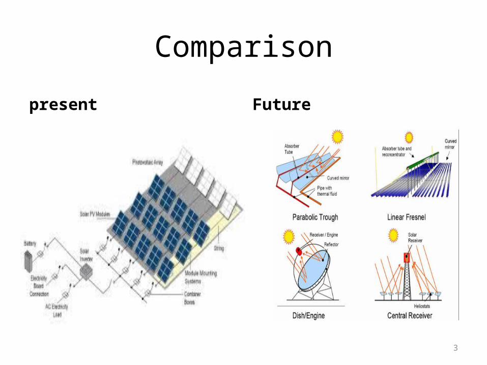
Comparison
present Future

Solar Power Potential Globally:
4
5
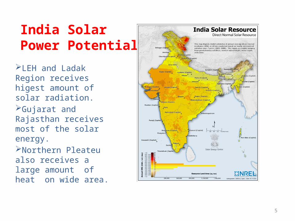
India Solar Power Potential
LEH and Ladak Region receives higest amount of solar radiation.Gujarat and Rajasthan receives most of the solar energy.Northern Pleateu also receives a large amount of heat on wide area.

Concentrating Solar Technologies
Low Temperature (<100°C)
Flat Plate Collectors
Solar Chimney
Solar Pond
High Temperature- Point Focusing
(>400°C)
Central Tower
Parabolic Dish
Medium Temperature – Line Focusing (≈ 400°C)
Parabolic Trough
Fresnel Collectors
6
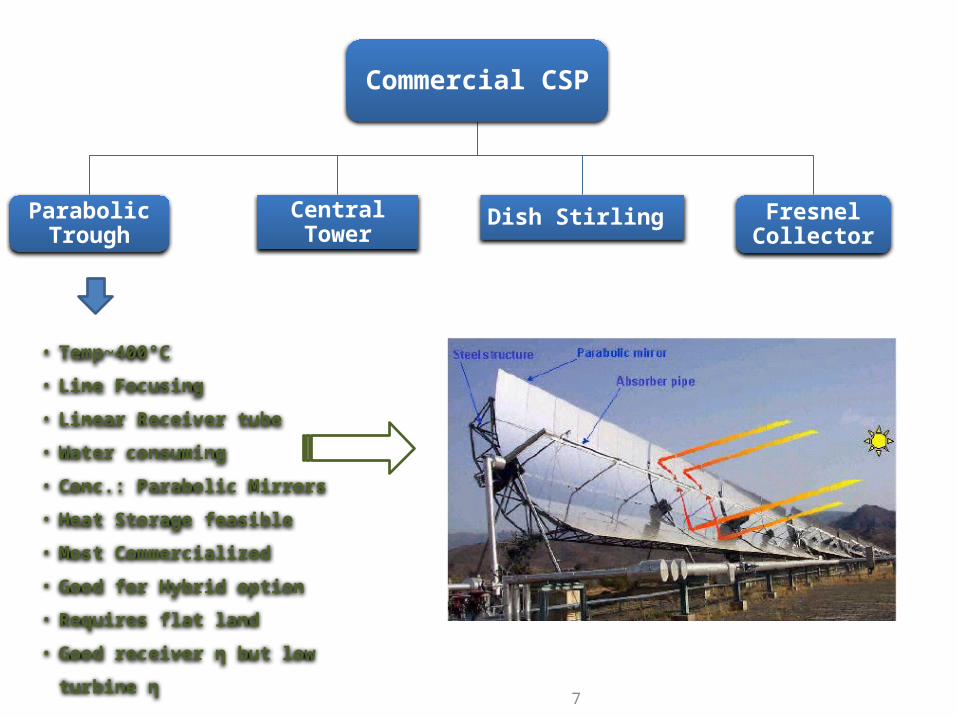
Commercial CSP
Parabolic Trough
Central Tower
Dish Stirling Fresnel Collector
7
• Temp~400°C
• Line Focusing
• Linear Receiver tube
• Water consuming
• Conc.: Parabolic Mirrors
• Heat Storage feasible
• Most Commercialized
• Good for Hybrid option
• Requires flat land
• Good receiver η but low turbine η

Commercial CSP
Parabolic Trough
Central Tower
Dish Stirling Fresnel Collector
8
• Temp~600-800°C
• Point Focusing
• Flat Conc. Mirrors
• Commercially proven
• Central Receiver
• Water consuming
• Heat Storage capability
• Feasible on Non Flat sites
• Good performance for large capacity &
temperatures
• Low receiver η but good turbine η

Commercial CSP
Parabolic Trough
Central Tower
Dish Stirling Fresnel Collector
9
• Temp~700-800°C
• Point Focusing
• Uses Dish concentrator
• Stirling Engine
• Generally 25 kW units
• High Efficiency ~ 30%
• Dry cooling
• No water requirement
• Heat storage difficult
• Commercially under development
• Dual Axis Tracking
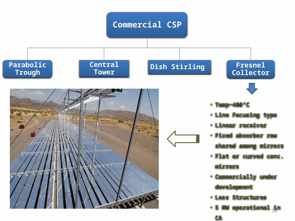
Commercial CSP
Parabolic Trough
Central Tower
Dish Stirling Fresnel Collector
10
• Temp~400°C
• Line Focusing type
• Linear receiver
• Fixed absorber row shared
among mirrors
• Flat or curved conc. mirrors
• Commercially under
development
• Less Structures
• 5 MW operational in CA

CSP Power - Brief Good DNI range ≥ 5-6 kWh/sq.m/day Capital Cost: $ 4-8 Million / MW (Increases with Heat Storage) Land Required: ~ 6-10 acres / MW Generation Potential: 25-35 MW / sq.km Units Generated: 1.81 Million Units / year (Increases with Heat Storage)
Capacity Factor: 20 – 25% (Can be increased to 40% using Heat storage)
COGN: $ 0.10 - 0.20 / kWh Lifespan: ~ 40 years, PPA’s are generally for 20-25 years Pay back Period: 5-12 years (Depends on the Tariff, subsidies, incentives)
Installation Period: ~ 2-3 years (Capacity dependent)
11

Existing and In-pipeline capacity
12
Source: Estela 2010 (Figures subject to 2009-10 scenario)
Current Status:
• Operational- ~1.2 GW; Spain 732.4 MW, US 507.5 MW, Iran 17.3 MW, etc.
• Under Construction- ~2.2 GW; Spain 1.4 GW, US 650 MW, India 28.5 MW, etc.

Commercialized Project Analysis
Andasol 1, 2 & 3Andasol 1- First Project in EuropeCapacity: 50 MWLat- 37°13’ N, Long.- 3°4’ W, 1100m above sea levelLocation: Granada Province, Southern Spain
Andasol 3Under Const. - Mid-2011
Andasol 1Nov. 2008
Andasol 2June 2009
13

Andasol 1- Specifications
Annual DNI: 2,136 kWh / sq.m. A
Technology Used: Parabolic Trough – Skal-ET 150
Land Utilization: ~ 195 Hectares (9.6 Acres/MW)
Construction Period: July 2006 – October 2008
Estimated Lifespan: 40 years
Entire Efficiency: ~28% peak, ~ 15% annual avg.
Capacity Factor: 20%
Units Generated: upto 180 GWh / Year
Uses Heat storage and Wet Cooling systems
14

Major Component- Specifications
Solar Field: Area: 510,120 m2 209,664 mirrors – 580, 500 sq.m. ~ 90 km receiver pipes (Schott Solar & Solel Solar) Field η = ~ 70% peak, 50% annual avg. Sustains wind speed of 13.6 m/s
Heat Storage: • Nitrate Molten Salt type (60% NaNO3 + 40% kNO3)• Two Tank Indirect: Cold- 292°C, Hot- 386°C• Storage: 28,000t • Back up: 7.5 Hours
Water Cooling Systems: • 870,000 cu.m./year• 1.2 gal/kWh
15

Working
16

Key Points
Capital Cost: $ 380 Million
Financing: Equity- 20%, Debt- 80%
Carbon Emission reduction: 150,000 tonnes/year
Electricity Supply Contract: Endesa
Feed In Tariff: EUR 0.27 / kWh ($ 0.38 /kWh)
PPA: Date- Sept. 15 / 2008, Tenure- 25 years
Electricity to 200,000 people
Annual O & M jobs: 40
17
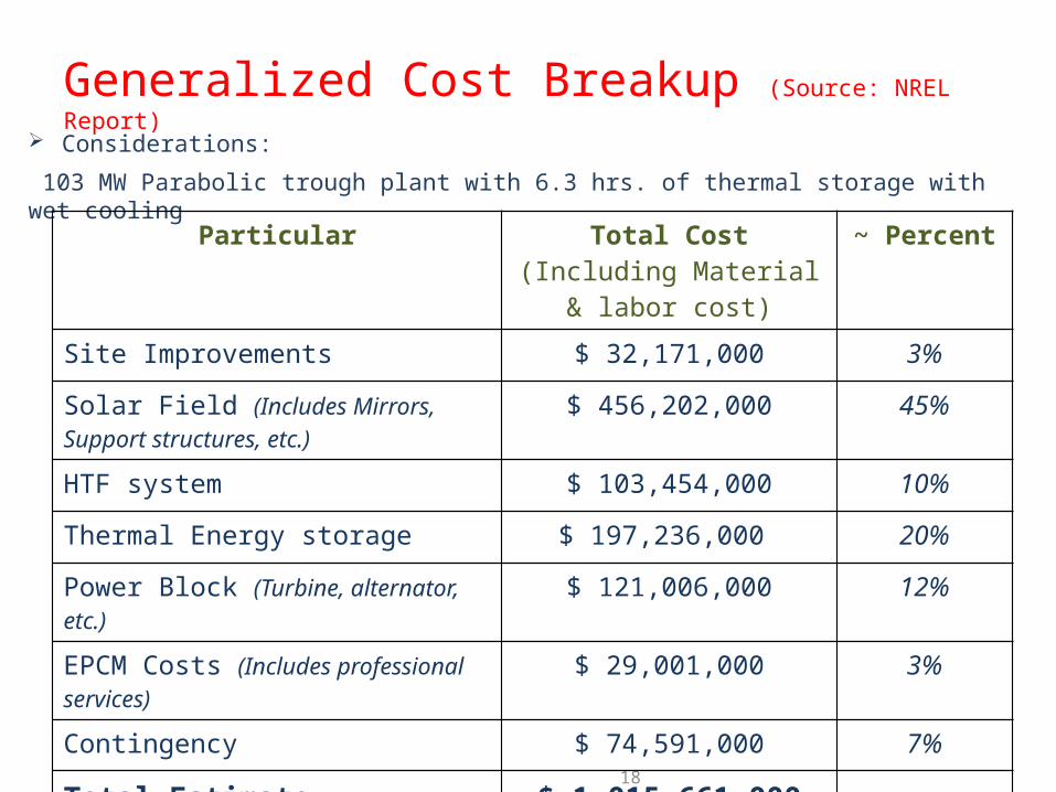
Generalized Cost Breakup (Source: NREL Report)
Considerations:
103 MW Parabolic trough plant with 6.3 hrs. of thermal storage with wet cooling
18
Particular Total Cost (Including Material & labor cost)
~ Percent
Site Improvements $ 32,171,000 3%
Solar Field (Includes Mirrors, Support structures, etc.)
$ 456,202,000 45%
HTF system $ 103,454,000 10%
Thermal Energy storage $ 197,236,000 20%
Power Block (Turbine, alternator, etc.) $ 121,006,000 12%
EPCM Costs (Includes professional services) $ 29,001,000 3%
Contingency $ 74,591,000 7%
Total Estimate $ 1,015,661,000
Cost per kW $ 9,861
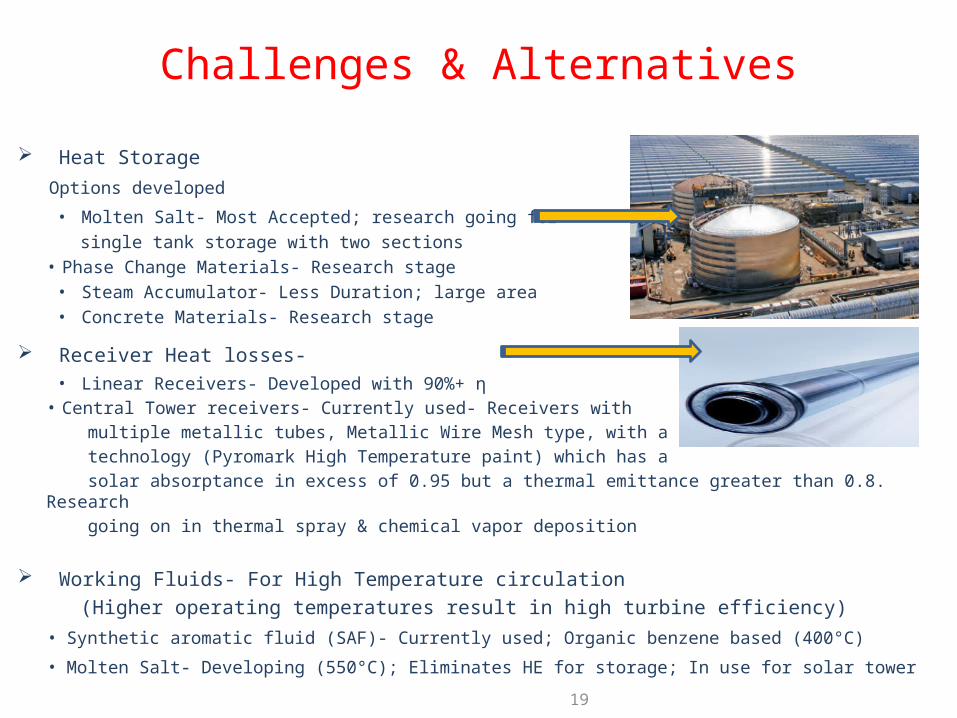
Challenges & Alternatives
Heat Storage
Options developed
• Molten Salt- Most Accepted; research going for
single tank storage with two sections• Phase Change Materials- Research stage• Steam Accumulator- Less Duration; large area• Concrete Materials- Research stage
Receiver Heat losses-• Linear Receivers- Developed with 90%+ η• Central Tower receivers- Currently used- Receivers with
multiple metallic tubes, Metallic Wire Mesh type, with a coating
technology (Pyromark High Temperature paint) which has a
solar absorptance in excess of 0.95 but a thermal emittance greater than 0.8. Research
going on in thermal spray & chemical vapor deposition
Working Fluids- For High Temperature circulation
(Higher operating temperatures result in high turbine efficiency)
• Synthetic aromatic fluid (SAF)- Currently used; Organic benzene based (400°C)
• Molten Salt- Developing (550°C); Eliminates HE for storage; In use for solar tower 19

Challenges & Alternatives
Water Consumption- Cooling Towers, Steam cycle make-up &
Mirror cleaning
• Wet cooling: ~ 865gal/MWh; Currently used; Water consumption
• Dry cooling: ~78gal/MWh; Developing stage, Costlier, low thermal η
• Hybrid cooling: ~338gal/MWh; Developing stage
NREL Findings for southwest US: Switching from 100% wet to 100% dry cooling will result in levelized cost of electricity (LCOE) increase of approximately 3% to 8% for parabolic trough plants, but reduces water consumption by 90 %
Receiver Materials- For Sustaining High Temp and pressure;
Research going on for developing high nickel alloy materials
High Capital Costs
Low Capacity Factors 20

Heat Storage option – Electricity Supply after Sunset
Process Heat Generation
Hybrid Option
Good for High temperature regions
Predictable and reliable power (less variable)
Water desalination along with electricity generation (Adv. In Middle east &
N. Africa)
21
Advantages over Competitive Technologies (Eg. PV & Wind)
Other Benefits:
Carbon Emission Reduction- CDM benefits Each square meter of CSP can avoid annual emissions of 200 to 300 kilograms (kg) of carbon dioxide, depending on its configuration.
No Fuel or its transportation cost - Substitutes Fossil Fuel use
Energy Security
High share of local contents
Employment Generation

Feasible Applications
Utility / Commercial scale Domestic/small Scale
22
Electricity Generation
• Stand alone
• Grid projects
• Hybrid projects
Industrial Process
Heat
• Boiling
• Melting
• Sterilizing
Cooling systems
Water Desalination
Hot Water collectors
Solar HVAC
Solar steam Cooking
Solar Ovens/cookers
Solar Food dryers
SOPOGYMicro-CSP: SopoFlare

Development Measures
Attractive FiT, SREC and Policy Mechanisms; Eg: SREC Mechanism in NJ, CA
Tax credits /Rebates; Like: ITC of 30% in US
Grid Interconnection with HVDC; Eg: DESERTEC project
Low Interest Loans, RPS and long tenure PPA’s
On-site Resource Assessment Stations- Reliable resource Database
Setting up Demonstration Projects on Emerging Technologies
Combining CSP with existing conventional projects
R & D in major challenge areas
Promote Domestic manufacturing - Cheaper equipment costs for developers
Government Land allotments; Forming SEZ’s, Solar farms for large scale
installations
23

Thank You
Earth receives around 174 Petawatts of energy from sun and only a small part of it is sufficient to meet the annual world electricity consumption of 20 Trillion kWh
Thank You