Embed Size (px)
DESCRIPTION
Citation preview

Chapter 8
81
Artificial actuation systems
I N T R O D U C T I O N
Chapter 7 described methods for artificial support of the impaired motor control system by means of passive mechanical systems. In addition or alternatively, active actuation may be part of the support system. In the case of stimulation of paralyzed muscles (Functional Electrical Stimulation), the actuators of the body are artificially actuated (section 8.2). Alternatively, artificial actuators may be applied (section 8.3). Actuators with dynamic behavior comparable to physiological muscles have been designed, but also other actuators have been proposed.
Controller:Artificialcontroller
Motors:Artificialactuators
Orthosis/Prosthesis
Sensors:ArtificialsensorsArtificial
SensoryFeedback
Forces
Movement
IntentionController:Central NervousSystem (CNS)
Motors:Muscles
Sensors:PhysiologicalSensorySystem
Physiological
ArtificialFES
Activation
PhysiologicalSensoryFeedback
1Skeletalsystems
Plant:
externalload
Figure 8-1 Schematic block diagram of an assistive system that supports the impaired neuromuscular system. Subject of this chapter is artificial actuation.
OBJECTIVES
This chapter will • show that power exchange and dynamic characteristics are important aspects to
consider when designing actuation systems for human motor function • present how paralyzed muscles can be stimulated and therefore used as artificially
controlled actuators of the human body • give an overview of artificial actuators in several physical domains which are
applicable for actuation of human mobility.

Biomechatronics
82
CONTENTS
8.1 Actuation
When designing actuators for support of human motor functions, several aspects need to be considered: • What is the required power exchange with the human body (Hannaford et al.
1990)? In some applications actuators continuously supply energy (active system). This may be unpractical for ambulatory systems, since it requires relatively large storage of energy to be carried by the user. Alternatively, actuators may store surplus energy at one instance, while releasing it at another moment in time, possibly at another joint. If no net energy is exchanged the actuator is called passive.
• What are the required dynamic characteristics? The actuators dynamically interact with the human body. They can be considered as dynamic loads to the human body, while the human body also acts as a load to the actuator. It is therefore important that the dynamic characteristics of the actuators are well adapted to the dynamics of the human motor system and requirements of the task to be performed (Lemay et al. 1998). A minimal requirement is that the load – body system is stable.
It should be noted that power exchange is directly related to the dynamic characteristics of the actuators and the body. Actuators can be conceived as a system that imposes a dynamic relation between an effort and flow quantity in the physical domain of operation (table 8-1 and figure 8-2) (see e.g. EL course Dynamic Systems and (Hannaford et al. 1990)).
Physical Domain effort quantity flow quantity electrical potential difference current mechanics (translational) force velocity mechanics (rotational) moment angular velocity hydraulic (liquid) / pneumatic (gas)
pressure flow
Table 8-1 effort and flow quantities defined in several physical domains.
humanmotorsystem
effort (F, V)
flow(v,I)
actuator
humanmotorsystem
effort (F, V)
flow(v,I)
actuatora.
b.
Figure 8-2 (a) The dynamic interaction between actuator and actuated system is characterized by the relation between the effort both systems impose on each other and their flow (b) This interaction can also be represented by a so called power bond.

Chapter 8 Artificial actuation systems
83
The power exchange between actuator and actuated system is given by the time integral of the product of effort and flow.
PROBLEM 8-1 ENERGY EXCHANGE DURING CYCLIC TASKS
Consider the dynamic interaction between the human body and an actuator during the performance of a cyclical motor task, like walking. Figure 8-3 represents the relation between effort and flow during one cycle. Show that the area surrounded by this trajectory in effort – flow space represents the energy exchange per cycle between both systems (work done by one system on the other).
effort
flow
work done in one cycle
Figure 8.3 Trajectory in effort-flow space representing one cycle of interaction between an actuator and the human body. the surface area surrounded by this trajectory represents the energy exchange per cycle between both systems, or the work done by the actuator during this cycle.
8.2 Artificial actuators
Actuators used in artificial human motor control should be designed to interact in an optimal manner with the human motor control system. Especially the dynamic characteristics and the power exchange with the human body are important (see paragraph 8.1).
Actuators normally transfer energy from one domain (input domain) to another domain (output domain). In the case of mechanical actuators used in human motor control the output domain is the mechanical domain. Actuators with several input domains have been designed for human motor control support (Hannaford et al. 1990), (Seth et al. 1990): • mechanical springs and dampers (mechanical input domain). The use of
mechanical springs and dampers are most straight-forward. In most cases it concerns mechanical components with fixed characteristics.
• Electrical motors. Electrical motors are in principle controlled effort sources. The principle of operation is the generation of Lorentz forces by electromagnetic induction acting on a coil with an electrical current positioned in a magnetic field. An electrical DC motor can be transferred into a position actuator by applying a feedback control system, feeding back position and velocity (servo controller).

Biomechatronics
84
Efforts have been made to design electrical DC motors which behave like a spring with varying offset lengths (stiffness control) (Fasse 1995).
• hydraulic actuators. Hydraulic actuators are in principle controlled flow sources because of the high incompressibility of the fluid in these systems. Force and impedance control require additional control systems around the actuator. Hydraulic controllable dampers are being used in the knee joint of controlled above knee prostheses (e.g. Otto Bock). Figure 8-4 gives an example of a hydraulic actuator used in a leg prosthesis design, coupling knee and ankle.
Figure 8-4. Example of an hydraulic actuator applied in a prosthetic leg design, coupling knee and ankle function. The design enables energy transfer from knee to ankle. Energy is generated at the knee during the stance phase of gait and used for push-off at the ankle at the transition from stance to swing phase (Koganezawa et al. 1987). This coupling is also reported to be functional in walking stairs.

Chapter 8 Artificial actuation systems
85
• pneumatic actuators Because of the compressibility of air, pneumatic actuators are much more compliant than hydraulic actuators by nature. Pneumatic muscle-like pneumatic actuators have been designed (artificial muscle, McKibben Muscle: figure 8-5) (Hannaford et al. 1990). These actuators consist of a bladder in which air can be flown, surrounded by a mesh of stiff material (e.g. nylon). These actuators have a relative large maximum tensile force as compared to the more regular piston actuators (Hannaford et al. 1990)
Figure 8-5 Pneumatic actuators with muscle like properties (McKibben type). These actuators consist of a bladder in which air can be flown, surrounded by a mesh of stiff material (e.g. nylon) (Hannaford et al. 1990). Inflating the actuator increases the stiffness and the zero-force length of the actuator.
8.3 Actuating the muscular actuation system of the body
Muscles are the motors of the human body. They are activated by electrical impulses (action potentials) transported along the nerve (chapter 2). If a muscle is paralysed because of an upper motor neuron lesion, the muscle and the peripheral nerves are still intact. Under this condition, a paralyzed muscle can be actuated artificially by inducing electrical currents through the nerve fiber membranes. This can be achieved by: • intracellular activation: electrode is positioned in the nerve fibers. This method is
only used in physiological experiments. • extracellular stimulation. Volume conduction currents can be generated in the
tissue by: • electrical current injection (electrical stimulation). • magnetically induced currents (magnetic stimulation).
8.3.1 ELECTRICAL OR MAGNETIC STIMULATION AND MEMBRANE DYNAMICS
Muscles consist of functional units, which are called motor units (see chapter 3). Each motor unit is activated by a motor neuron in the spinal cord. The axon of the motor neuron transports action potentials to the endplates of the motor unit fibers (figure 8-6). Each action potential elicits a short contraction of the muscle fibers of the motor unit (twitch contraction).

Biomechatronics
86
myelinated motor neuron axonα
muscle fibersof a motor unit
αmotorneuron
actionpotential
Vm
Figure 8-6 Muscles consist of motor units. The muscle fibers of a motor unit are activated by action potentials which are transported along the axons of the α-motor neurons.
If a muscle is paralyzed, it does not receive action potentials from the motor neuron and therefore does not contract. If the paralysis is due to a central lesion in the spinal cord or higher brain centers, the motor neurons and their axons may still be intact, but do not receive contraction commands from higher centres. In such a case, the axons can be stimulated artificially by inducing electrical currents through the membranes of the axons. This may result in the generation of action potentials which are transported to the muscle, where they trigger contractions (Mortimer 1996). Electrical currents can be induced in the tissue by injecting electrical currents via electrodes (electrical stimulation: figure 8-7) or by generating varying magnetic fields which generate electrical currents in the tissue by electromagnetic induction (magnetic stimulation: figure 8-8).
myelinated motor neuron axonα
muscle fibersof a motor unit
αmotorneuron
actionpotential
VmJ
I
Figure 8-7 Muscles can be activated by electrically stimulating the α-motor neuron axons using electrodes which inject current in the tissue (electrical stimulation).

Chapter 8 Artificial actuation systems
87
myelinated motor neuron axonα
muscle fibersof a motor unit
αmotorneuron
actionpotential
VmJ
I
Bt
Figure 8-8 Muscles can be activated by magnetically by inducing electrical currents in the tissue by electromagnetic induction (magnetic stimulation)
In the case of electrical stimulation, electrodes can be positioned on the skin (transcutaneous stimulation), in the tissue via electrodes through the skin (percutaneous) or in the tissue via electrodes connected to implanted stimulator (subcutaneous) (figure 8-9).
Figure 8-9 Transcutaneous, percutaneous and implanted stimulation electrodes
Two processes determine the excitation of motor axons by electrical or magnetic stimulation: 1. The electrical current density field induced in the tissue by the electrical or
magnetic stimulation. The tissue can be conceived as a volume conductor. 2. The change of nerve fiber membrane potential resulting from the induced
membrane currents. The first process (electrical current field induction in the tissue) is mostly considered as a static process, although it has some dynamics which normally is non-dominant in comparison with the nerve fiber membrane dynamics, and therefore can be discarded. The dominant dynamics in the artificial activation of nerve fibers are the membrane dynamics (second process). They have to be taken into account when analysing nerve fiber stimulation (McNeal 1976), (Ranck 1975): the membrane of a myelinated nerve fiber can be conceived as a network of parallel resistors and capacitors (RC network) (figure 8-10). At regular instances the myeline sheet is interrupted. Only at these places, the nodes of Ranvier, current can flow through the membrane.

Biomechatronics
88
Let us define nV to be the change of membrane potential of node n from it’s steady
state reference value rV . nV is related to the intraneural potential niV , and externeural
potential neV , at node n as follows:
rnenin VVVV −−= ,, (8.1)
nV relates to the second order difference of the membrane potentials and extraneural
potentials at node n and the neighboring nodes n-1 and n-2:
)2()2()( ,1,1,11 nenenei
mnnn
i
mndt
dVmm VVV
R
RVVV
R
RVCR n −+=−+−+ +−+−
(8.2)
The second order difference term of the extraneural potentials nenene VVV ,1,1, 2−+ +−
is the input term to this differential equation. It is called activation function (Rattay 1989).
Figure 8-10 The electrical behavior of the membrane of a myelinated motor axon can be modeled as an RC-network. The fiber is insulated at the outside by a myeline sheath, which is interrupted at regular distances (nodes of Ranvier). The axon is excited if the membrane potential is changed beyond a certain threshold.
The nerve fiber is excited if the membrane potential surpasses a certain threshold. Beyond this threshold, the membrane capacitance changes in a time dependent and nonlinear way, as described by the Hudgin and Huxley or Frankenhauser-Huxley equations (see course electrophysiological signals), (Frankenhaeuser et al. 1964), (Chiu et al. 1979).
In the case of a rectangular stimulation pulse ( eV at all nodes is constant during the
pulse and is zero before and after the pulse) the membrane potential can be increased by increasing either pulse width or amplitude. The relation between stimulation pulse width and amplitude yielding threshold stimulation of a nerve fiber is called the strength-duration curve (figure 8-9a) (Mortimer 1996). For long stimulation pulse width, the threshold pulse amplitude reaches an asymptote, called rheobase. The pulse width at which the threshold pulse amplitude is twice the rheobase is called chronaxy. The strength-duration curve normally fits the characteristics of a parallel resistor and

Chapter 8 Artificial actuation systems
89
capacitor network (figure 8-11b), which is associated with the membrane dynamics of the excited fiber (figure 8-10). It should however be noted that the excitation is not
only determined by the time constant mmm CR=τ of the membrane, but also of the
distances between the nodes of Ranvier, the intraneural resistance iR and the external
potentials eV at several nodes of Ranvier (see figure 8-10 and formula 8.2). Therefore,
an effective time constant RC=τ is obtained. If the strength-duration curve is fitted with the characteristics of a parallel resistor and capacitor (figure 8-11b), the following relation between pulse width PWt and
amplitude PAI is found (expressed in terms of rheobase and chronaxy):
chronaxyPW ttrheobase
PA
eI
I/2ln
1
1−−
= (8.3)
The effective time constant of the excitation dynamics RC=τ can therefore be related to the chronaxy in the following manner:
2lnchronaxyt
=τ (8.4)
Measurement of the strength-duration curve is a simple tool used in neurophysiology to determine the effective excitation dynamics of the fiber.
PW
PAI
rheobase
tchronaxy
excitation
no excitation
a. b.
R C
t
I
Figure 8-11 (a) The strength-duration curve is the relation between stimulus pulse width ( PWt ) and amplitude ( PAI ) for which a nerve fiber is stimulated
at threshold level. Excitation occurs above and no excitation below this curve. (b) The strength-duration curve satisfies the characteristics of an RC network, when injecting a current pulse and determining the relation between amplitude and width of the pulse which results in a certain potential difference over the network.
Biomechatronics
90
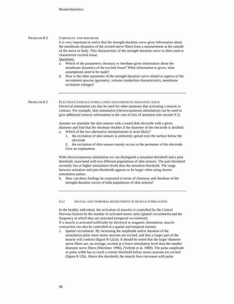
PROBLEM 8-2 CHRONAXY AND RHEOBASE
It is very important to notice that the strength-duration curve gives information about the membrane dynamics of the excited nerve fibers from a measurement at the outside of the nerve or body. This characteristic of the strength-duration curve is often used to characterize excited tissue. Questions:
a. Which of the parameters chronaxy or rheobase gives information about the
membrane dynamics of the excited tissue? What information is given, what assumptions need to be made?
b. How is the other parameter of the strength-duration curve related to aspects of the recruitment process (geometry, volume conduction characteristics, membrane excitation voltage)?
PROBLEM 8.3 ELECTROCUTANEOUS STIMULATION AND STRENGTH-DURATION CURVE
Electrical stimulation can also be used for other purposes that activating a muscle to contract. For example, skin stimulation (electrocutaneous stimulation) can be used to give additional sensory information in the case of loss of sensation (see section 9.3).
Assume we stimulate the skin sensors with a round disk electrode with a given diameter and find that the rheobase doubles if the diameter of the electrode is doubled. a. Which of the two alternative interpretations is most likely?
1. the excitation of skin sensors is uniformly spread over the surface below the electrode
2. the excitation of skin sensors mainly occurs at the perimeter of the electrode. Give an explanation.
With electrocutaneous stimulation we can distinguish a sensation threshold and a pain threshold, associated with two different populations of skin sensors. The pain threshold normally lies at higher stimulation levels than the sensation threshold. The range between sensation and pain thresholds appears to be larger when using shorter stimulation pulses. b. How can these findings be expressed in terms of chronaxy and rheobase of the
strength-duration curves of both populations of skin sensors?
8.3.2 SPATIAL AND TEMPORAL RECRUITMENT IN MUSCLE STIMULATION
In the healthy individual, the activation of muscles is controlled by the Central Nervous System by the number of activated motor units (spatial recruitment) and the frequency at which they are activated (temporal recruitment). If a muscle is activated artificially by electrical or magnetic stimulation, muscle contraction can also be controlled in a spatial and temporal manner: 1. Spatial recruitment: By increasing the amplitude and/or duration of the
stimulation pulse more motor neurons are excited, and thus a larger part of the muscle will contract (figure 8-12a,b). It should be noted that the larger diameter nerve fibers are, on average, excited at a lower stimulation level than the smaller diameter nerve fibers (Mortimer 1996), (Veltink et al. 1988). The pulse amplitude or pulse width has to reach a certain threshold before motor neurons are excited (figure 8-12b). Above this threshold, the muscle force increases with pulse

Chapter 8 Artificial actuation systems
91
amplitude or width until a saturation level is reached, at which the whole muscle is excited.
2. Temporal recruitment: If the stimulation frequency is increased, the muscle force increases (figure 8-12c,d). Muscle twitch contractions sum in a nonlinear manner: the muscle forces saturates above a certain stimulation frequency. This frequency depends on the characteristics of the muscle (fast or slowly contracting). At low stimulation frequencies the summation of twitches results in a ripple on the force signal, which reduces at higher frequencies.
c.
b. d.
a.
Figure 8-12 Spatial and temporal recruitment. When stimulation pulse amplitude and/or width are increased, more motor neuron fibers are excited, the thickest fibers first (a), resulting in increased muscle force (b). When stimulation frequency is increased, the motor neuron fibers are more often excited (c), resulting in increased muscle force (d).
PROBLEM 8-4 RECRUITMENT CURVE
a. Explain the sigmoid shape of the recruitment curve in figure 8-12.
b. the recruitment curve of figure 8-12 is the resultant of recruitment curves of motor units with differently sized motor neurons. Show in a drawing how the recruitment curves of differently sized motor neurons differ.
8.3.3. PHYSIOLOGICAL VERSUS ARTIFICIAL ACTIVATION OF MUSCLES
Differences between physiological muscle activation and activation by artificial stimulation: • in the case of physiological activation all functional parts of the muscle (motor
units) are activated asynchronously, while in artificial stimulation, the whole muscle, or large parts of the muscle, are stimulated synchronously.

Biomechatronics
92
• in case of physiological activation, motor units are recruited in a physiological order (in most cases from small to large: size princple of Henneman), while in artificial stimulation, the motor units are recruited in inverse order, because thicker nerve fibers (connected to larger motor units) have a lower threshold for stimulation than smaller nerve fibers (connected to smaller motor units). It should be stated however, that methods have been developed to obtain the physiological recruitment order with artificial stimulation.
Many attempts have been made to improve artificial stimulation of muscles such that it is closer to the physiological way of muscle activation: • Sequential activation of different populations of motor units by use of multiple
stimulation electrodes have been proposed. The limitation of this approach is the limited spatial selectivity associated with electrical stimulation, resulting in an overlap between the groups of motor neuron fibers which are excited by different electrodes (figure 8-13) (Veltink et al. 1989), (Thomsen et al. 1997), (Deurloo et al. 1998), (Grill et al. 1997), (Grill et al. 1995).
• Restoring natural recruitment order by anodal blocking of the larger nerve fibers (Fang et al. 1991), making use of the nonlinear membrane dynamics (Grill et al. 1997) or high frequency stimulation (Solomonow et al. 1983), (Grill et al. 1995)
Figure 8-13 Overlap of spatial recruitment areas of different electrodes because of limited spatial selectivity of electrical stimulation.
8.3.4 MODELS OF ELECTRICALLY ACTIVATED MUSCLES
If paralyzed muscles activated by electrical or magnetic stimulation are to be used as actuators in a neural prosthetic system, their dynamic properties need to be taken into account. Muscle dynamics have already been discussed in chapter 3, mainly under conditions of physiological activation. However, most of the physiological experiments on which this knowledge is based concern animal experiments in which the muscles were stimulated artificially. If muscles are activated by electrical or magnetic stimulation the dynamic characteristics are influenced by the fact that large parts of the muscle are activated synchronously and the recruitment order of motor units may not be in physiological order (see section 8.3.3). This aspects need to be included in dynamic models of stimulated muscles used as the basis for motor control strategies. The complexity of such models depend on the condition under which the muscle is being used: • If muscle force is to be controlled under isometric conditions (the muscle-tendon
complex does not vary in length), the muscle dynamics can be described by second order linear dynamic models (Bernotas et al. 1986; Baratta et al. 1989).

Chapter 8 Artificial actuation systems
93
The dynamics are dependent on muscle length and stimulation frequency (Bernotas et al. 1986; Huijing 1998). If the stimulation recruitment characteristics (relation between stimulation amplitude or pulse width and part of the muscle which is activated), the total model is consists of a static nonlinearity in series with a linear dynamic system (Hunter et al. 1986; Durfee et al. 1989) (figure 8-14).
• If muscle change length varies during contraction, essential non-linearities (e.g. muscle length and velocity dependencies: see chapter 3) need to be taken into account (Veltink et al. 1992; Franken et al. 1995).
Physiological experiments indicate that the actual dynamic behaviour of muscles is much more complex than assumed in most of the models used as a basis for FES (Huijing 1998), (Huijing 1999).
IPA
tPW
u Fu
IPA tPWor
staticnonlinearity
linearsecond order
dynamics
Figure 8-14 Under isometric conditions, the dynamics of electrically stimulated muscles can be modelled by a static nonlinearity (recruitment curve) in series with a linear dynamic system (Bernotas et al. 1986; Durfee et al. 1989). The dynamics are dependent on muscle length and stimulation frequency.
REFERENCES
Baratta R, Zhou B-H and Solomonow M (1989): Frequency resonse model of skeletal muscle: effect of perturbation level, and control strategy. Med. & Biol. Eng. & Comput. 27: 337-345.
Bernotas LA, Crago PE and Chizeck HJ (1986): A discrete-time model of electrically stimulated muscle. IEEE Transactions on Biomedical Engineering 33: 829-838.
Chiu SY, Ritchie JM, Bogart RB and Stagg D (1979): A quantitative description of membrane currents in rabbit myelinated nerve. J. Physiology 292: 149-196.
Deurloo KEI, Holsheimer J and Boom HBK (1998): Transverse tripolar stimulation of peripheral nerve: a modelling study of spatial selectivity. Medical and Biological Engineering and Computing 36: 66-74.
Durfee WK and Maclean KE (1989): Methods for estimating isometric recruitment curves of electrically stimulated muscles. IEEE Transactions on Biomedical Engineering 36: 654-667.
Fang Z-P and Mortimer JT (1991): A method to effect physiological recruitment order in electrically activated muscle. IEEE Transactions on Biomedical Engineering 38: 175-179.
Fasse ED (1995). Variable mechanical-impedance actuators - muscle-like? Control of ambulation using functional neuromuscular stimulation, topical workshop RAFT, University of Twente, Enschede, the Netherlands, University of Twente, pp. 19-25.
Franken HM, Veltink PH, Tijsmans R, Nijmeijer H and Boom HBK (1995): Identification of quadriceps - shank dynamics using randomized interpulse interval stimulation. IEEE Transactions on rehabilitation engineering 3: 182-192.

Biomechatronics
94
Frankenhaeuser B and Huxley AF (1964): The action potential in the myelinated nerve fibre of xenopus laevis as computed on the basis of voltage clamp data. J. Physiol. 171: 302-315.
Grill WM and Mortimer JT (1995): Stimulus waveforms for selective neural stimulation. IEEE Engineering in Medicine and Biology Society Magazine 14: 375-385.
Grill WM and Mortimer JT (1997): Inversion of the current-distance relationship by transient depolarization. IEEE Transactions on Biomedical Engineering 44: 1-9.
Hannaford B and Winters JM (1990). Actuator properties and movement control: biological and technical models. In: W. J.M. and S. L.-Y. Woo,eds., Multiple muscle systems - biomechanics and movement organization. New York, Springer Verlag. pp. 101-120.
Huijing PA (1998): Muscle, the motor of movement: properties in function, experiment and modelling. J. Electromyography and Kinesiology 8: 61-77.
Huijing PA (1999): Muscle as a collagen fiber reinforced composite material: force transmission in muscle and whole limbs. Journal of Biomechanics 32: 329-345.
Hunter IW and Korenberg MJ (1986): The identification of nonlinear biological systems: Wiener and Hammerstein cascade models. Biological Cybernetics 47: 135-144.
Koganezawa K, Fujimoto H and Kato I (1987): multifunctional above-knee prosthesis for stairs' walking. Prosthet. Orthot. Int. 11: 139-145.
Lemay MA, Hogan N and van Dorsten JW (1998): Issues in impedance selection and input devices for multijoint powered orthotics. IEEE Trans Rehabil Eng 6: 102-5.
McNeal DR (1976): Analysis of a model for excitation of myelinated nerve. IEEE Trans. on Biomed. Eng. Bme: 329-337.
Mortimer JT (1996). Motor Prostheses. In: Handbook of Physiology - The Nervous System II. New York, Oxford, Oxford University Press. pp. 155-187.
Ranck JB (1975): Which Elements are Excited in Electrical Stimulation of Mammalian Central Nervous System : A Review. Brain Research 98: 417-440.
Rattay F (1989): Analysis of Models for Extracellular Fiber Stimulation. IEEE Transactions on Biomedical Engineering 36: 676-682.
Seth B and Flowers WC (1990): generalized actuator concept for the study of the efficiency of energetic systems. Journal of Dynamic Systems, Measurement and Control 112: 233-238.
Solomonow M, Eldred E, Lyman J and Foster J (1983): Control of muscle contractile force through indirect high-frequency stimulation. Americal Journal of Physical Medicine 62: 71-82.
Thomsen M and Veltink PH (1997): Influence of synchronous and sequential stimulation on muscle fatigue. Medical and Biological Engineering and Computing 35: 186-192.
Veltink PH, Chizeck HJ, Crago PE and El-Bialy A (1992): Nonlinear joint angle control for artificially stimulated muscle. IEEE Transacttions on Biomedical Engineering 39: 368-380.
Veltink PH, Van Alste JA and Boom HBK (1988): Simulation of intrafascicular and extraneural nerve stimulation. IEEE Transactins on Biomedical Engineering 35: 69-75.
Veltink PH, Van Veen BK, Struijk JJ, Holsheimer J and Boom HBK (1989): A modeling study of nerve fascicle stimulation. IEEE Transactions on Biomedical Engineering 36: 683-691.