Embed Size (px)
Citation preview

ANALOG COMMUNICATIONS
MAIN TOPICS
Introduction to Communication SystemsAmplitude ModulationAM ReceiversAM TransmittersSuppressed-Carrier AM Systems
Elements of a Communication System
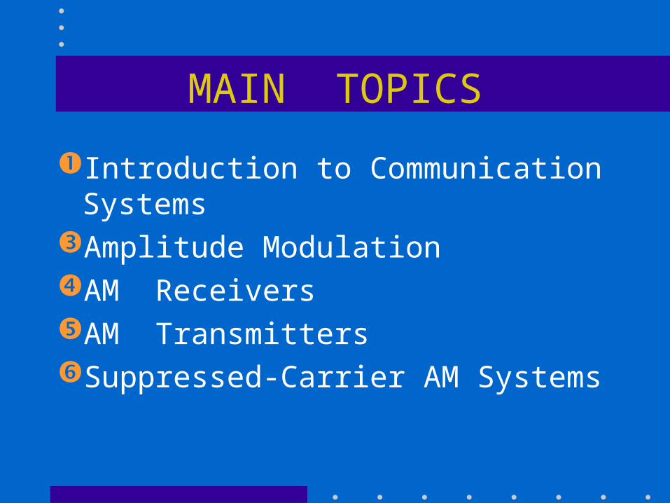
Communication involves the transfer of information or intelligence from a source to a recipient via a channel or medium.
Basic block diagram of a communication system:
Source Transmitter Receiver Recipient
Brief Description
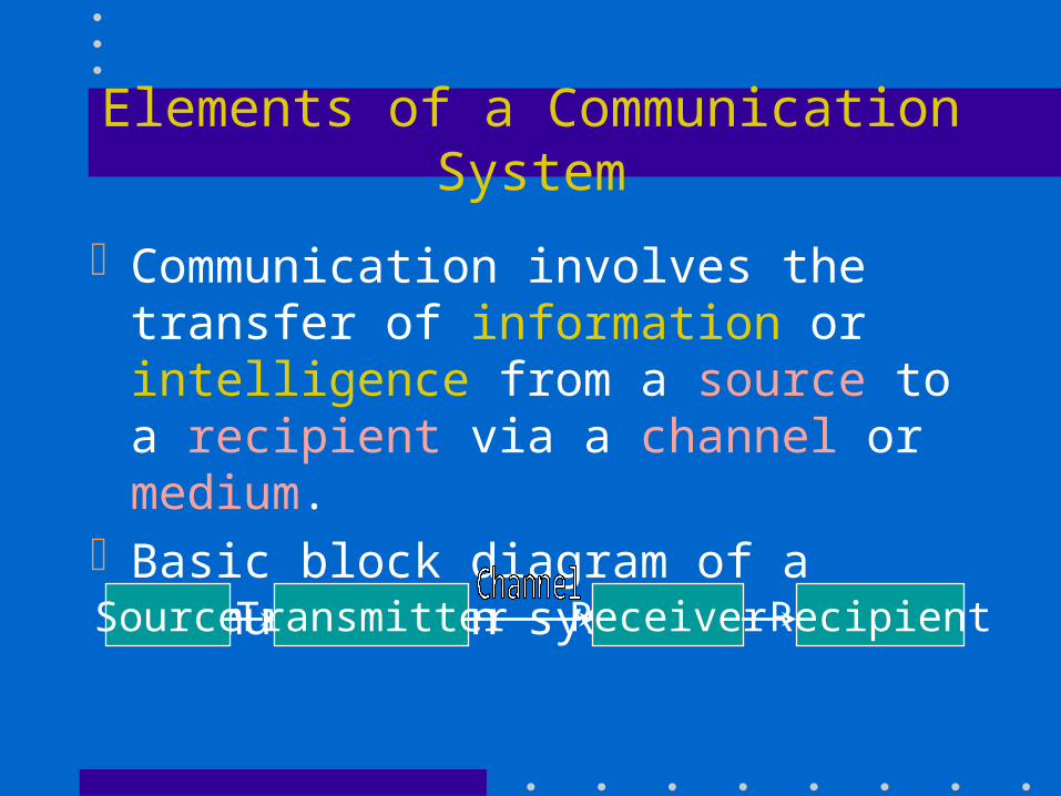
Source: analogue or digital Transmitter: transducer, amplifier,
modulator, oscillator, power amp., antenna Channel: e.g. cable, optical fibre, free space Receiver: antenna, amplifier, demodulator,
oscillator, power amplifier, transducer Recipient: e.g. person, speaker, computer
Modulation
Modulation is the process of impressing information onto a high-frequency carrier for transmission.
Reasons for modulation:– to prevent mutual interference between stations– to reduce the size of the antenna required
Types of modulation: AM, FM, and PM
Information and Bandwidth
Bandwidth required by a modulated signal depends on the baseband frequency range (or data rate) and the modulation scheme.
Hartley’s Law: I = k t B
where I = amount of information
k = a constant of the system
t = time available
B = channel bandwidth
Frequency Bands
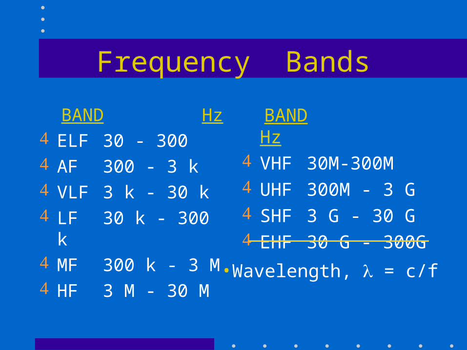
BAND Hz ELF 30 - 300 AF 300 - 3 k VLF 3 k - 30 k LF 30 k - 300 k MF 300 k - 3 M HF 3 M - 30 M
BAND Hz VHF 30M-300M UHF 300M - 3 G SHF 3 G - 30 G EHF 30 G - 300G
•Wavelength, = c/f
Types of Signal Distortion
Types of distortion in communications:harmonic distortion intermodulation distortionnonlinear frequency responsenonlinear phase responsenoise interference
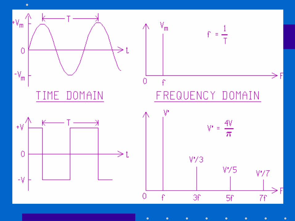
Time and Frequency Domains
Time domain: an oscilloscope displays the amplitude versus time
Frequency domain: a spectrum analyzer displays the amplitude or power versus frequency
Frequency-domain display provides information on bandwidth and harmonic components of a signal

Jean Baptiste Joseph Fourier (1768-1830)
Had crazy idea (1807): Any periodic function
can be rewritten as a weighted sum of Sines and Cosines of different frequencies.
Don’t believe it? – Neither did Lagrange,
Laplace, Poisson and other big wigs
– Not translated into English until 1878!
But it’s true!– called Fourier Series
– Possibly the greatest tool
used in Engineering
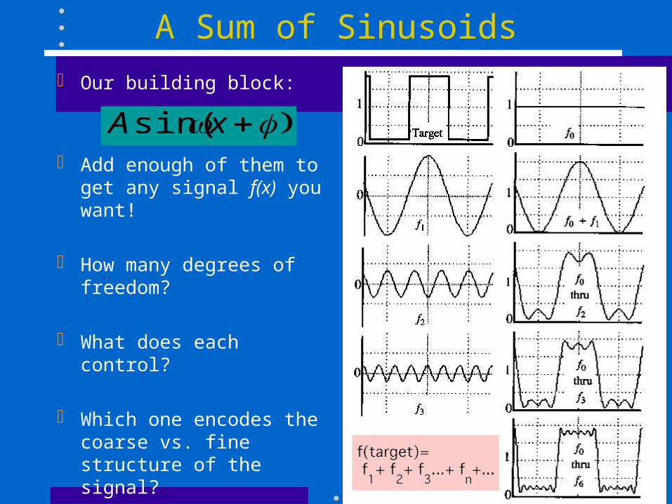
A Sum of Sinusoids
Our building block:
Add enough of them to get any signal f(x) you want!
How many degrees of freedom?
What does each control?
Which one encodes the coarse vs. fine structure of the signal?
xAsin(
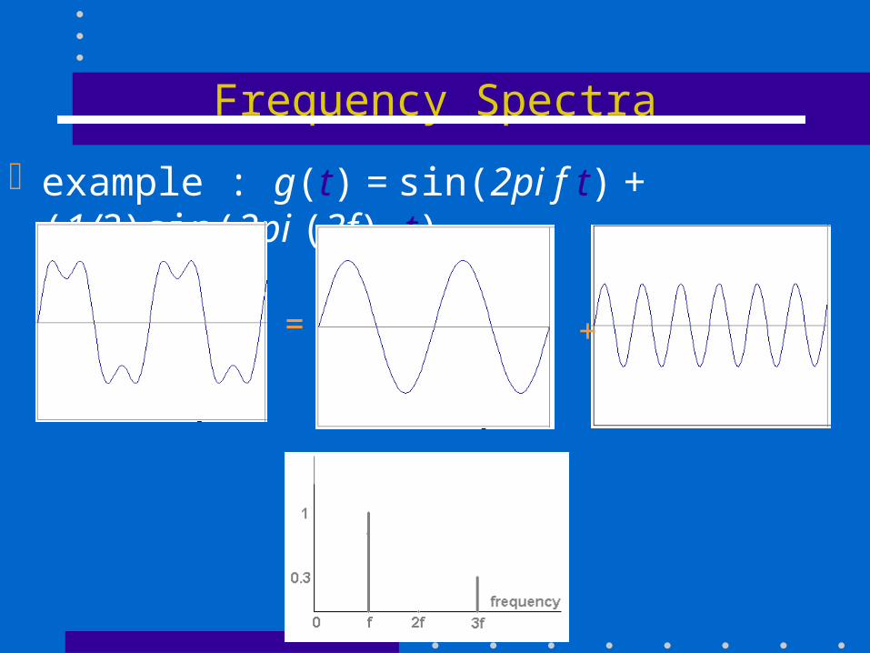
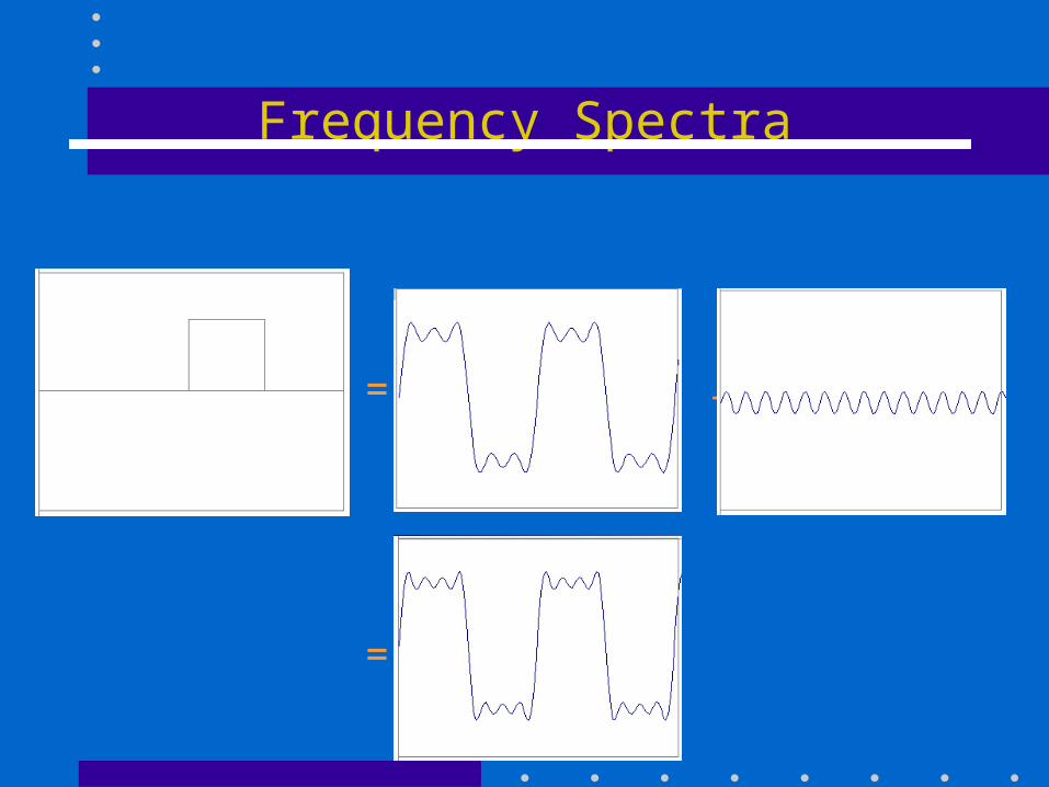
Frequency Spectra
example : g(t) = sin(2pi f t) + (1/3)sin(2pi (3f) t)
= +
= +
=
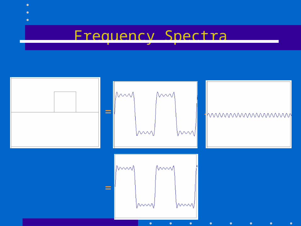
Frequency Spectra
= +
=
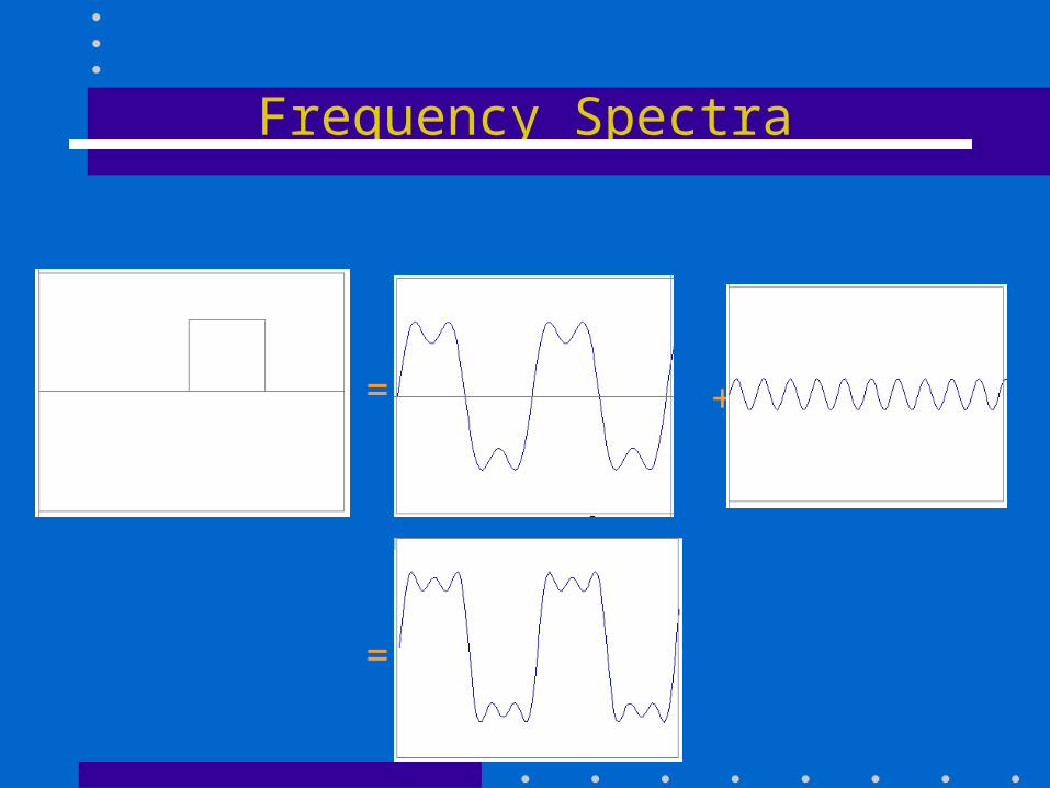
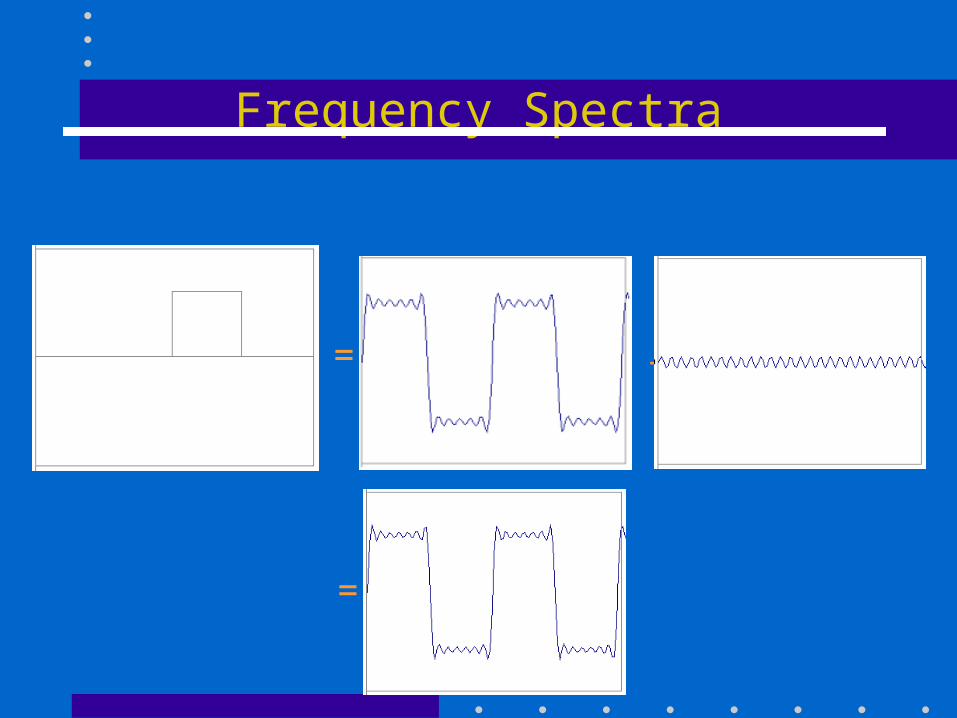
Frequency Spectra
= +
=
Frequency Spectra
= +
=
Frequency Spectra
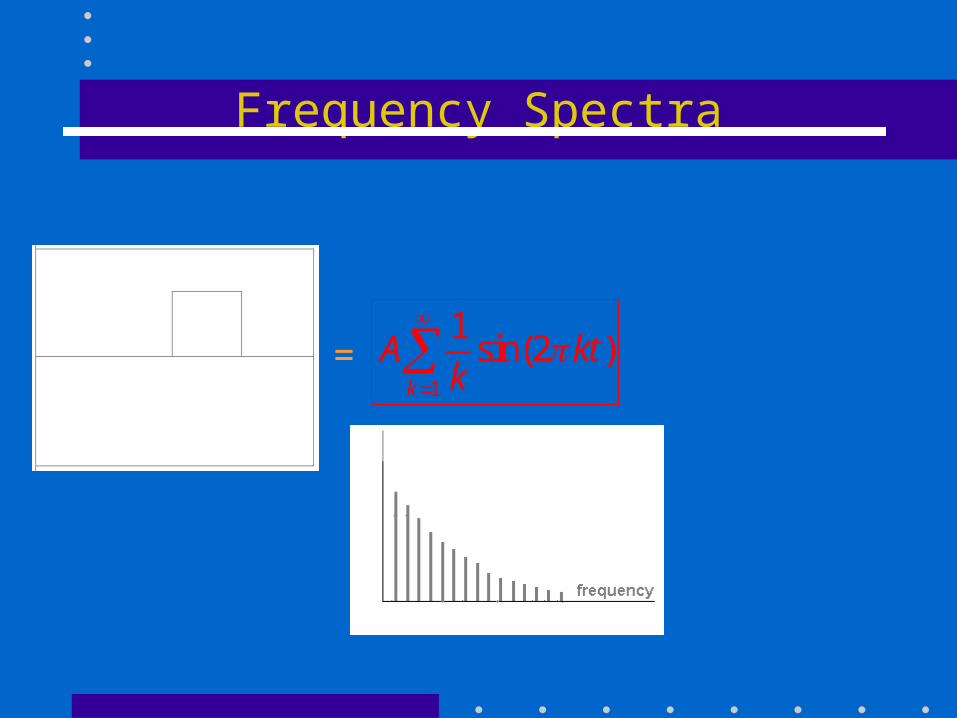
= 1
1sin(2 )
k
A ktk
Frequency Spectra
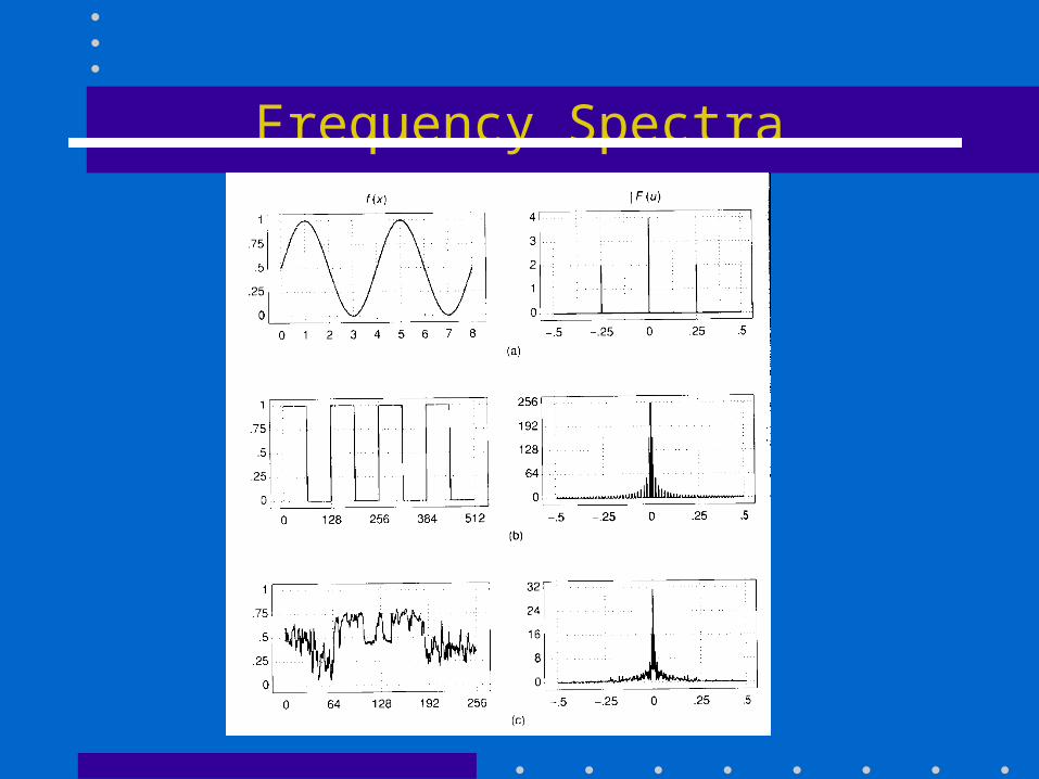
Frequency Spectra
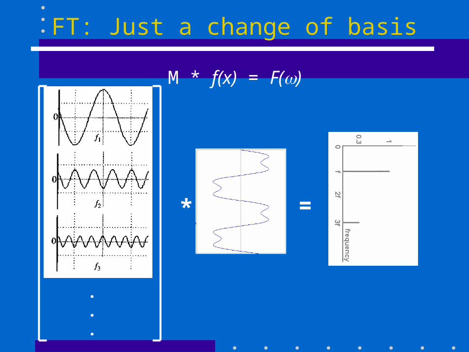
FT: Just a change of basis
.
.
.
* =
M * f(x) = F()
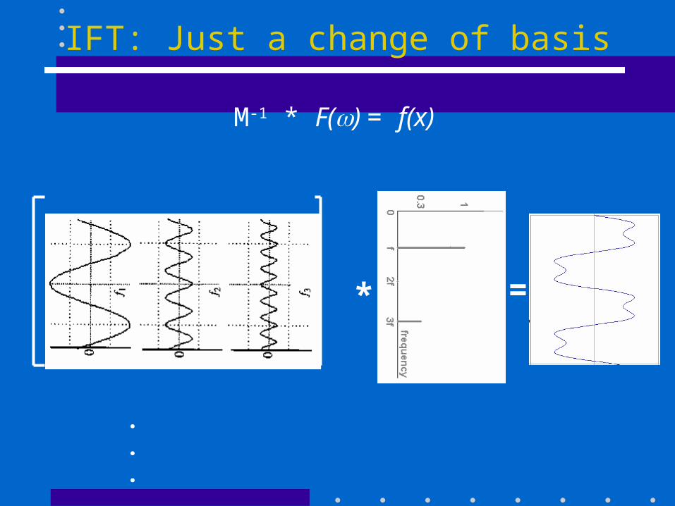
IFT: Just a change of basis
.
.
.
* =
M-1 * F() = f(x)
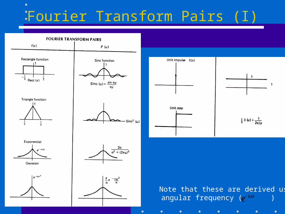
Fourier Transform Pairs (I)
angular frequency ( )iuxeNote that these are derived using
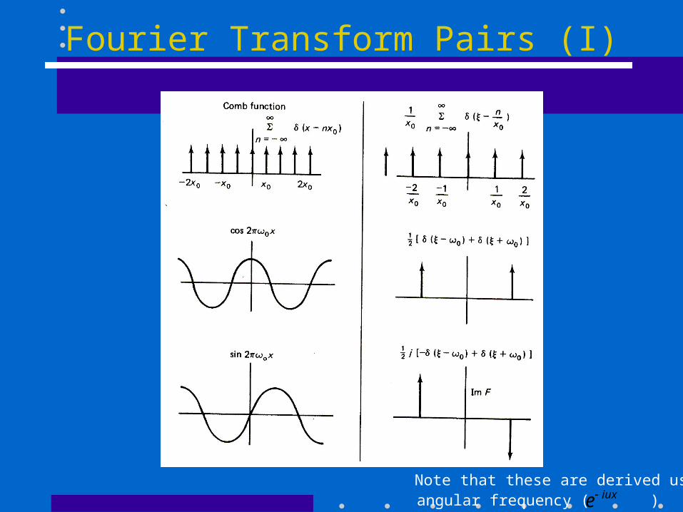
angular frequency ( )iuxeNote that these are derived using
Fourier Transform Pairs (I)
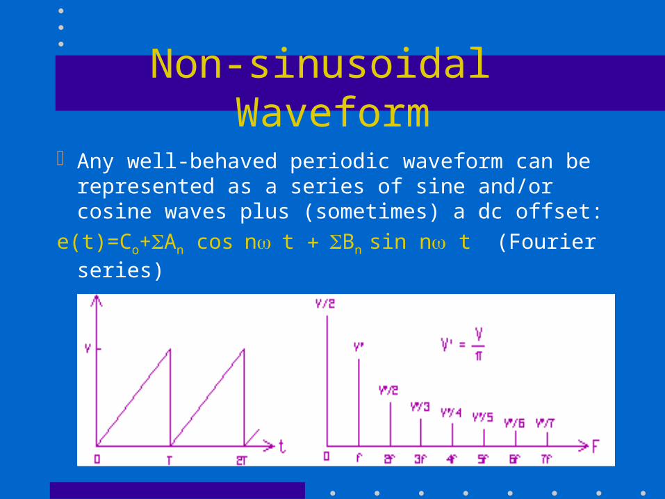
Non-sinusoidal Waveform
Any well-behaved periodic waveform can be represented as a series of sine and/or cosine waves plus (sometimes) a dc offset:
e(t)=Co+An cosnt Bn sin n t (Fourier series)
Effect of Filtering
Theoretically, a non-sinusoidal signal would require an infinite bandwidth; but practical considerations would band-limit the signal.
Channels with too narrow a bandwidth would remove a significant number of frequency components, thus causing distortions in the time-domain.
A square-wave has only odd harmonics
External Noise
Equipment / Man-made Noise is generated by any equipment that operates with electricity
Atmospheric Noise is often caused by lightning
Space Noise is strongest from the sun and, at a much lesser degree, from other stars
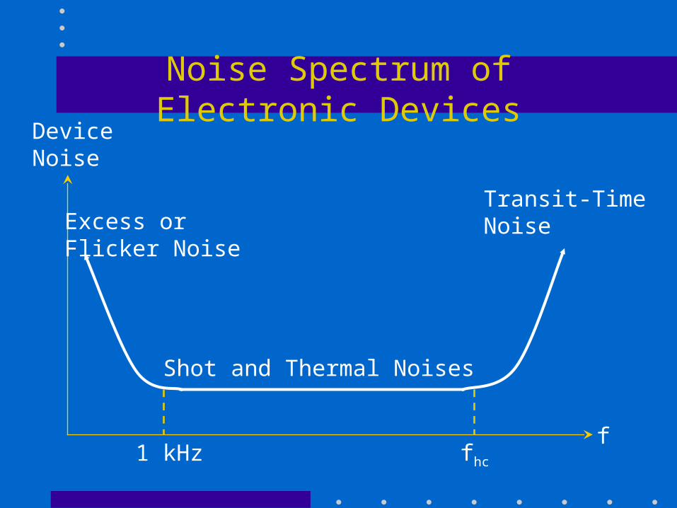
Noise Spectrum of Electronic DevicesDeviceNoise
Shot and Thermal Noises
Excess orFlicker Noise
Transit-Time Noise
1 kHz fhc
f
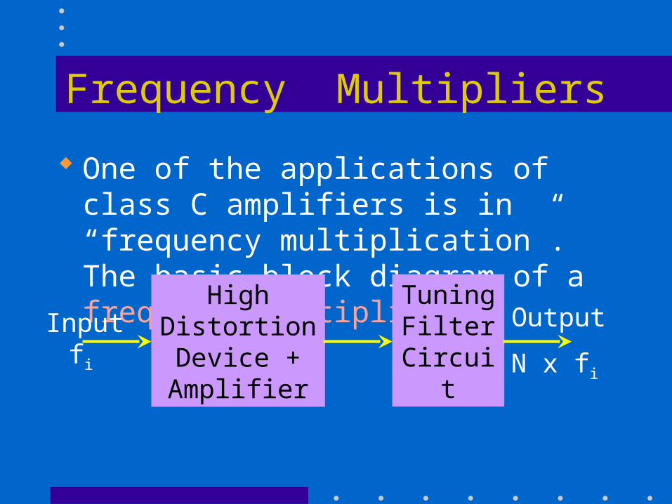
Frequency Multipliers
One of the applications of class C amplifiers is in “frequency multiplication”. The basic block diagram of a frequency multiplier:
High DistortionDevice +Amplifier
TuningFilter
Circuit
Inputfi
Output
N x fi
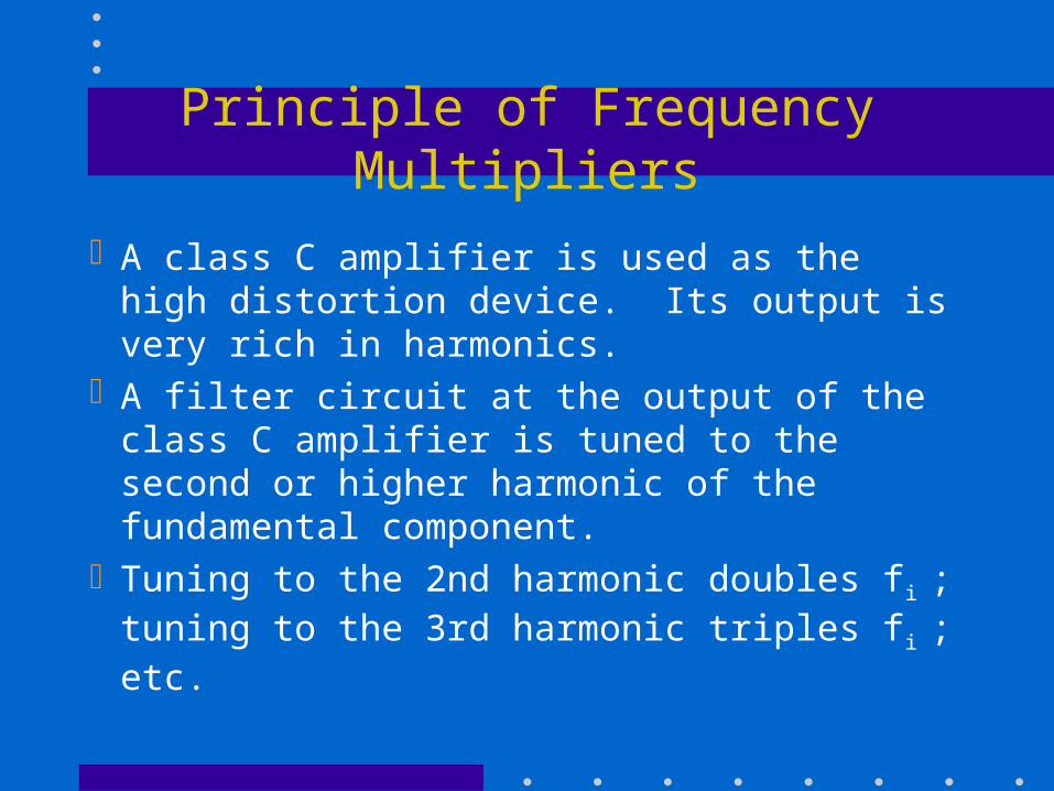
Principle of Frequency Multipliers
A class C amplifier is used as the high distortion device. Its output is very rich in harmonics.
A filter circuit at the output of the class C amplifier is tuned to the second or higher harmonic of the fundamental component.
Tuning to the 2nd harmonic doubles fi ; tuning to the 3rd harmonic triples fi ; etc.
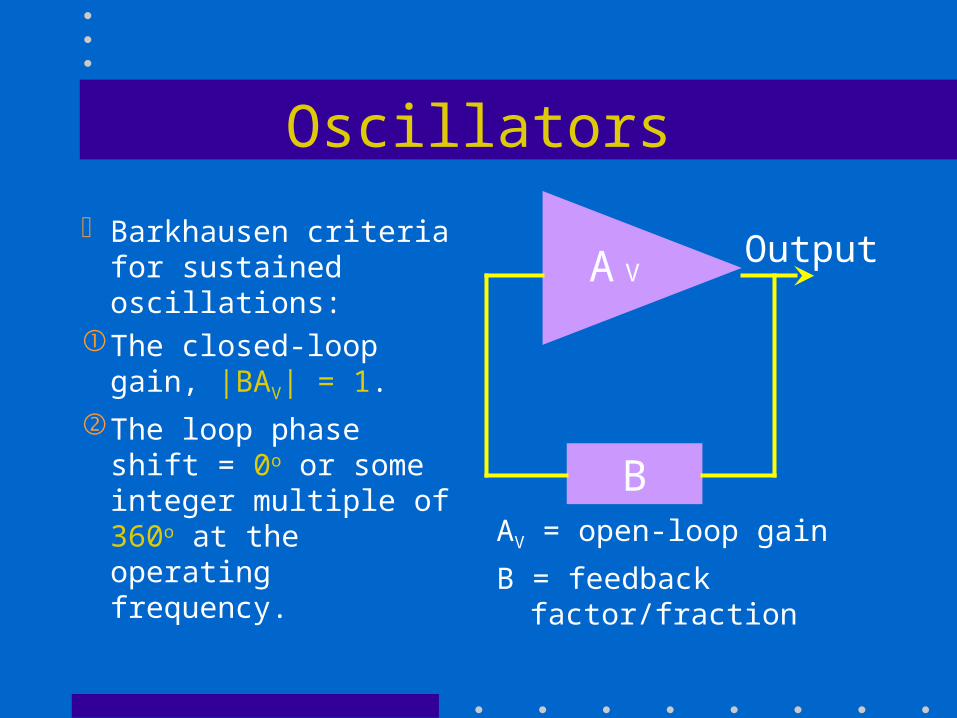
Oscillators
Barkhausen criteria for sustained oscillations:
The closed-loop gain, |BAV| = 1.
The loop phase shift = 0o or some integer multiple of 360o at the operating frequency. AV = open-loop gain
B = feedback factor/fraction
AV
B
Output
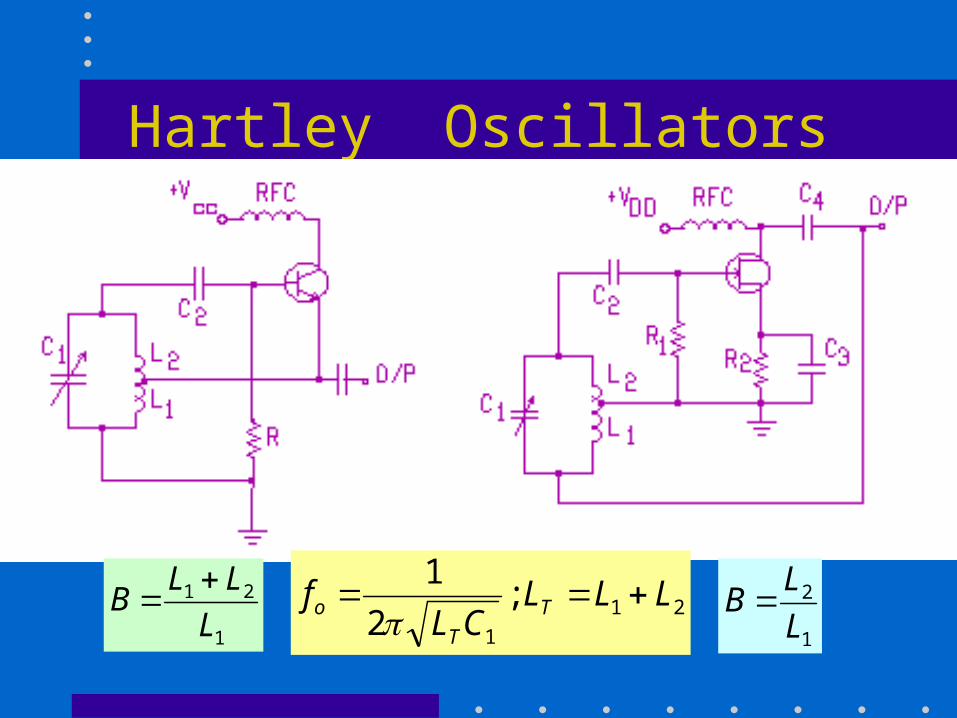
Hartley Oscillators
21
1
;2
1LLL
CLf T
T
o 1
21
L
LLB
1
2
L
LB
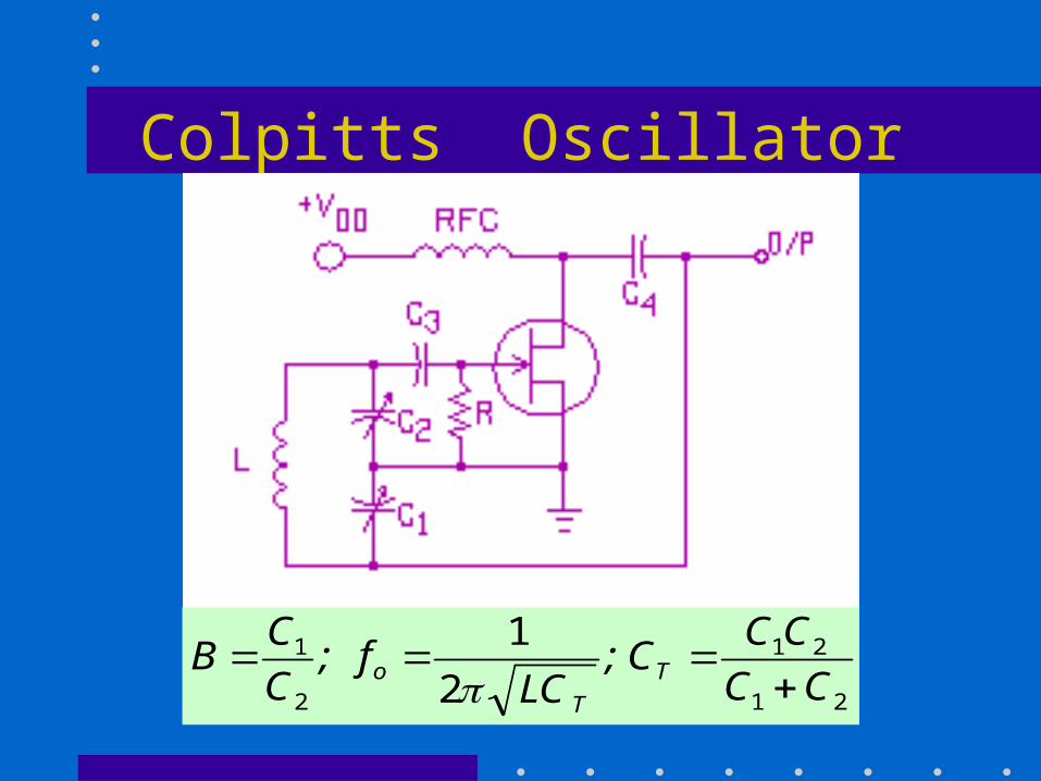
Colpitts Oscillator
21
21
2
1
2
1
CC
CCC;
LCf;
C
CB T
T
o
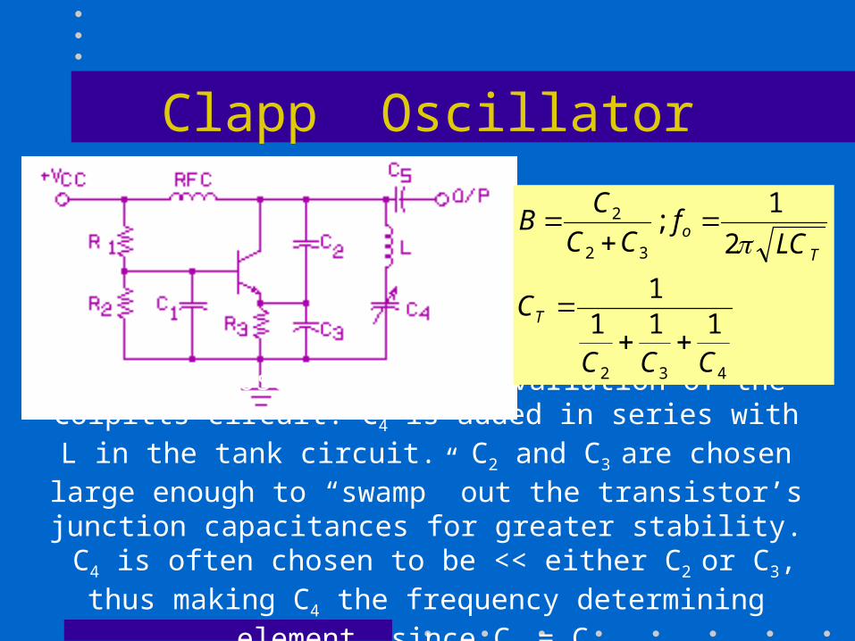
Clapp Oscillator
The Clapp oscillator is a variation of the Colpitts circuit. C4 is added in series with L in the tank circuit. C2 and C3 are chosen
large enough to “swamp” out the transistor’s junction capacitances for greater stability. C4 is often chosen to be << either C2 or C3,
thus making C4 the frequency determining element, since CT = C4.
432
32
2
1111
2
1;
CCC
C
LCf
CC
CB
T
T
o
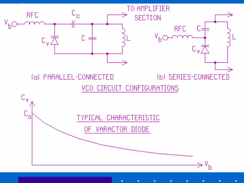
Voltage-Controlled Oscillator
VCOs are widely used in electronic circuits for AFC, PLL, frequency tuning, etc.
The basic principle is to vary the capacitance of a varactor diode in a resonant circuit by applying a reverse-biased voltage across the diode whose capacitance is approximately:
b
oV
V
CC
21
Mixers
A mixer is a nonlinear circuit that combines two signals in such a way as to produce the sum and difference of the two input frequencies at the output.
A square-law mixer is the simplest type of mixer and is easily approximated by using a diode, or a transistor (bipolar, JFET, or MOSFET).
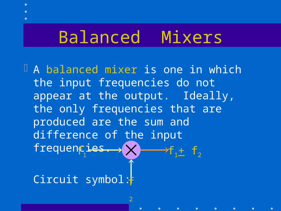
Balanced Mixers
A balanced mixer is one in which the input frequencies do not appear at the output. Ideally, the only frequencies that are produced are the sum and difference of the input frequencies.
Circuit symbol:f1
f2
f1+ f2
Equations for Balanced Mixer
Let the inputs be v1 = sin 1t and v2 = sin t.
A balanced mixer acts like a multiplier. Thus
its output, vo = Av1v2 = A sin 1t sin 2t.
Since sin X sin Y = 1/2[cos(X-Y) - cos(X+Y)]
Therefore, vo = A/2[cos(1-2)t-cos(t].The last equation shows that the output of the
balanced mixer consists of the sum and difference of the input frequencies.
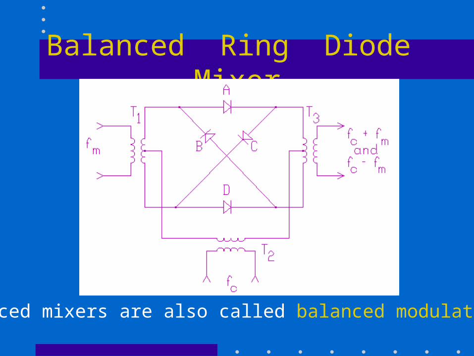
Balanced Ring Diode Mixer
Balanced mixers are also called balanced modulators.
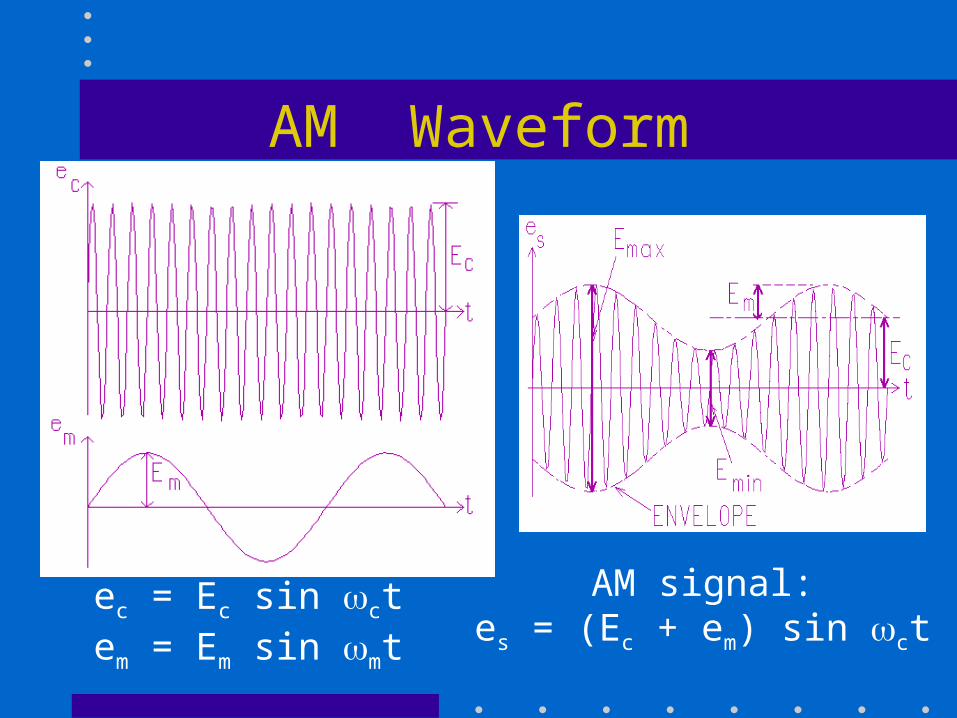
AM Waveform
ec = Ec sin ctem = Em sin mt
AM signal:es = (Ec + em) sin ct
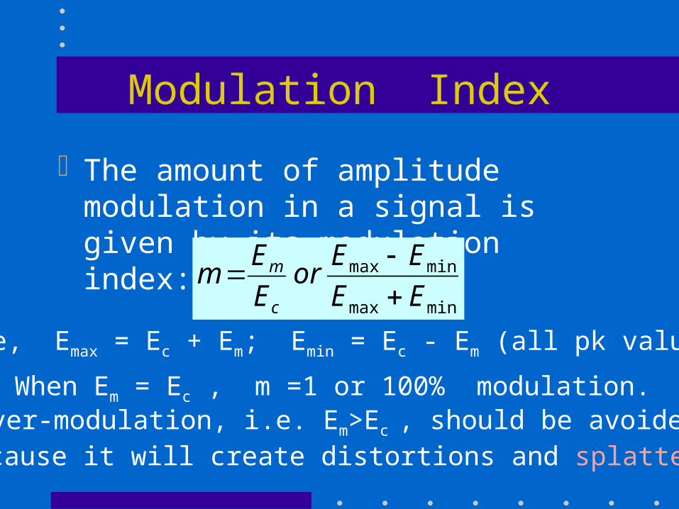
Modulation Index
The amount of amplitude modulation in a signal is given by its modulation index:
minmax
minmax
EE
EEor
E
Em
c
m
When Em = Ec , m =1 or 100% modulation.Over-modulation, i.e. Em>Ec , should be avoided
because it will create distortions and splatter.
where, Emax = Ec + Em; Emin = Ec - Em (all pk values)
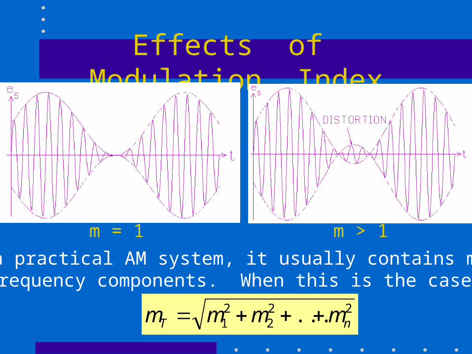
Effects of Modulation Index
m = 1 m > 1
In a practical AM system, it usually contains manyfrequency components. When this is the case,
222
21 ... nT mmmm
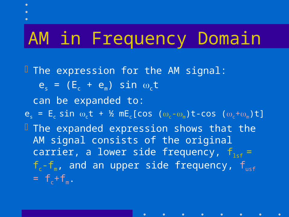
AM in Frequency Domain
The expression for the AM signal:
es = (Ec + em) sin ct
can be expanded to:es = Ec sin ct + ½ mEc[cos (c-m)t-cos (c+m)t]
The expanded expression shows that the AM signal consists of the original carrier, a lower side frequency, flsf = fc-fm, and an upper side frequency, fusf = fc+fm.
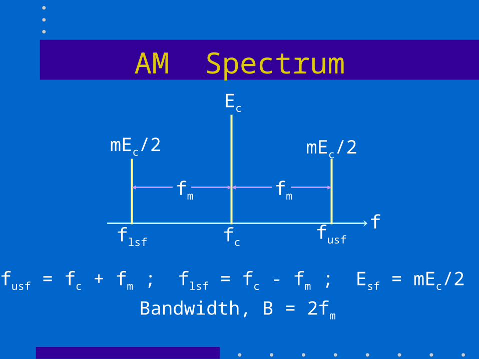
AM Spectrum
ffc
Ec
fusf
mEc/2mEc/2
flsf
fmfm
fusf = fc + fm ; flsf = fc - fm ; Esf = mEc/2
Bandwidth, B = 2fm
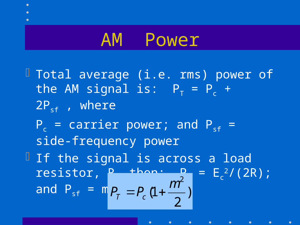
AM Power
Total average (i.e. rms) power of the AM signal is: PT = Pc + 2Psf , where
Pc = carrier power; and Psf = side-frequency power
If the signal is across a load resistor, R, then: Pc = Ec
2/(2R); and Psf = m2Pc/4. So,
)2
1(2m
PP cT
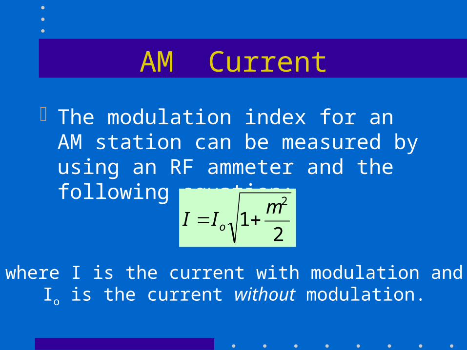
AM Current
The modulation index for an AM station can be measured by using an RF ammeter and the following equation:
21
2mII o
where I is the current with modulation and Io is the current without modulation.
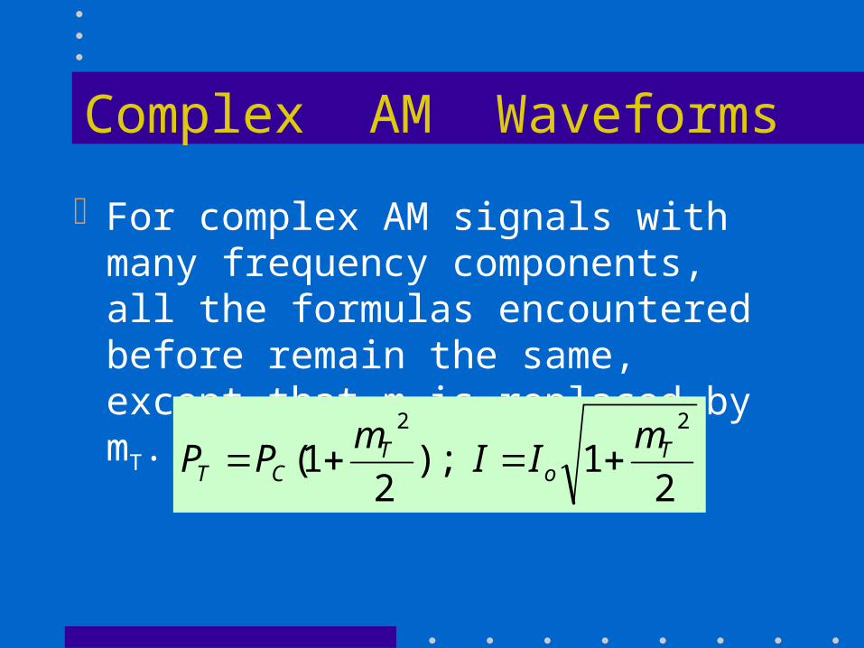
Complex AM Waveforms
For complex AM signals with many frequency components, all the formulas encountered before remain the same, except that m is replaced by mT. For example:
21);
21(
22T
oT
CT
mII
mPP
AM Receivers
Basic requirements for receivers:ability to tune to a specific signalamplify the signal that is picked upextract the information by demodulationamplify the demodulated signalTwo important receiver specifications:
sensitivity and selectivity
by H Chan, Mohawk College
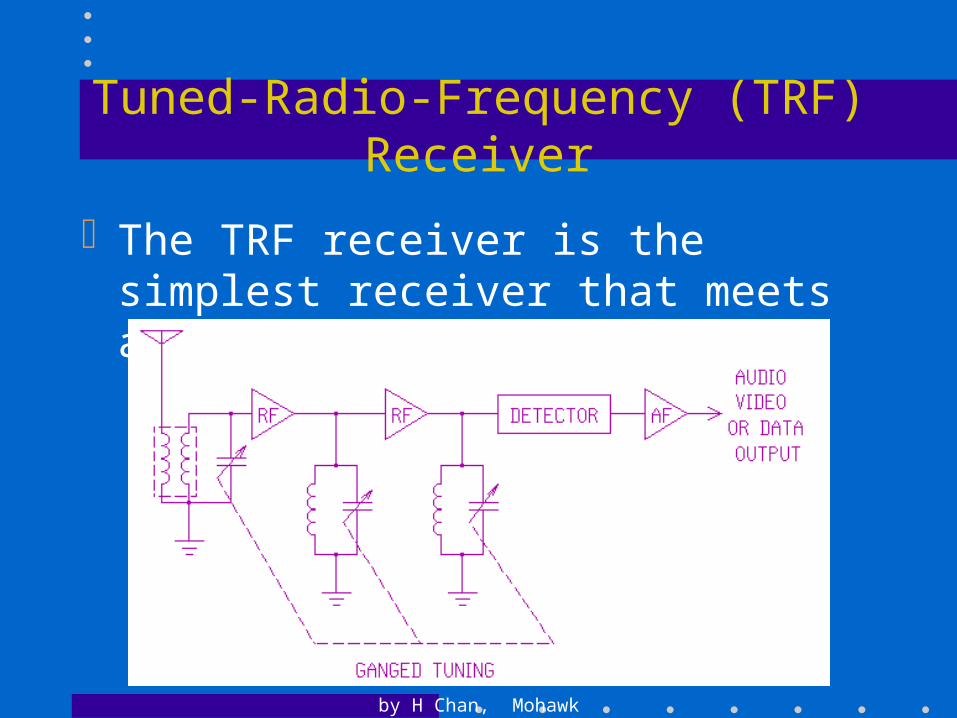
Tuned-Radio-Frequency (TRF) Receiver
The TRF receiver is the simplest receiver that meets all the basic requirements.
Superheterodyne Receiver
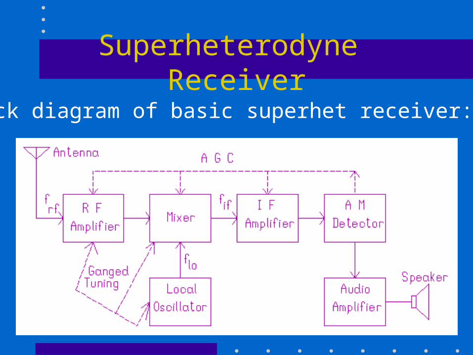
Block diagram of basic superhet receiver:
Antenna and Front End
The antenna consists of an inductor in the form of a large number of turns of wire around a ferrite rod. The inductance forms part of the input tuning circuit.
Low-cost receivers sometimes omit the RF amplifier.
Main advantages of having RF amplifier: improves sensitivity and image frequency rejection.
Mixer and Local Oscillator
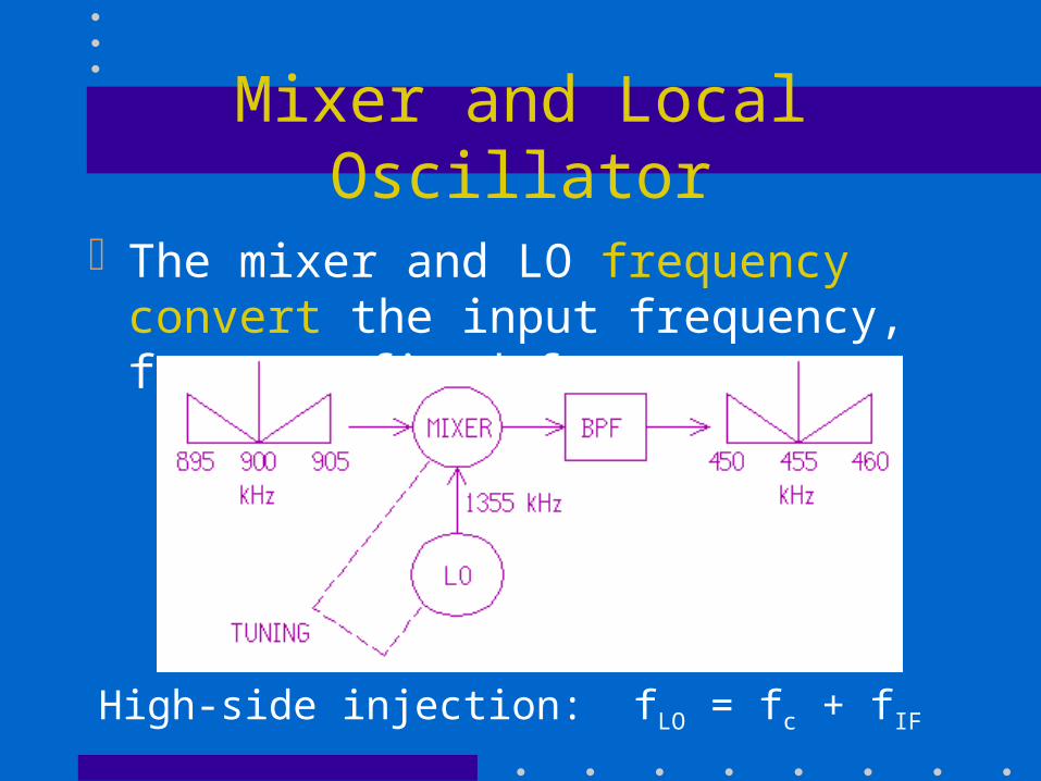
The mixer and LO frequency convert the input frequency, fc, to a fixed fIF:
High-side injection: fLO = fc + fIF
IF Amplifier and AGC
Most receivers have two or more IF stages to provide the bulk of their gain (i.e. sensitivity) and their selectivity.
Automatic gain control (AGC) is obtained from the detector stage to adjusts the gain of the IF (and sometimes the RF) stages inversely to the input signal level. This enables the receiver to cope with large variations in input signal.
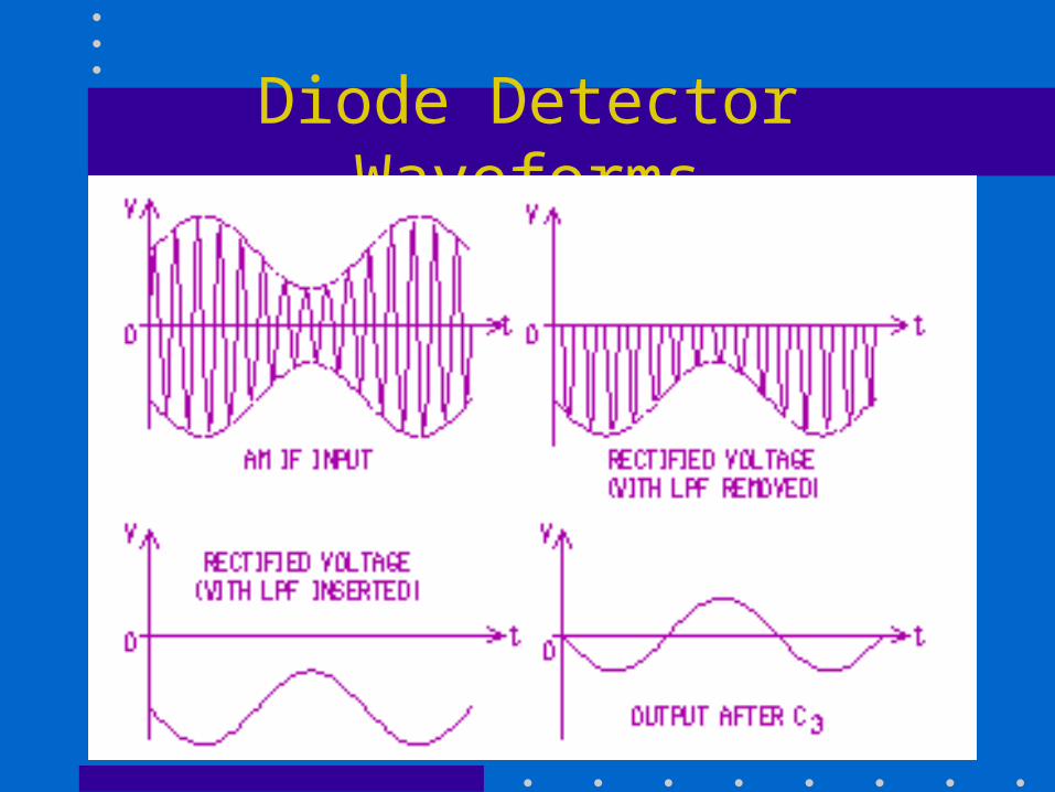
Diode Detector Waveforms
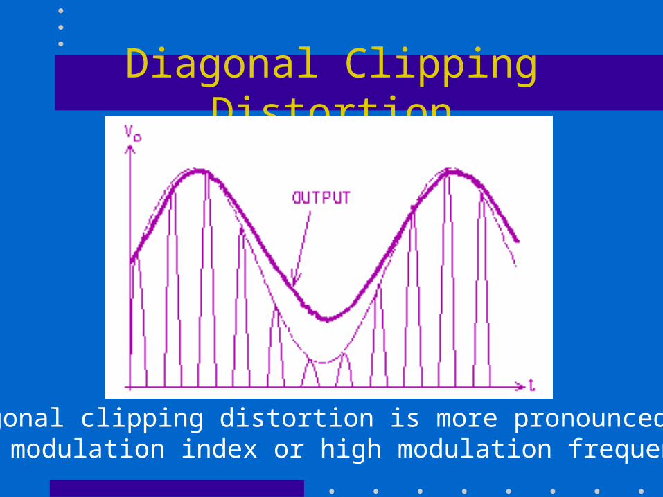
Diagonal Clipping Distortion
Diagonal clipping distortion is more pronounced athigh modulation index or high modulation frequency.
Sensitivity and Selectivity
Sensitivity is expressed as the minimum input signal required to produce a specified output level for a given (S+N)/N ratio.
Selectivity is the ability of the receiver to reject unwanted or interfering signals. It may be defined by the shape factor of the IF filter or by the amount of adjacent channel rejection.
Image Frequency
One of the problems with the superhet receiver is that an image frequency signal could interfere with the reception of the desired signal. The image frequency is given by: fimage = fsig + 2fIF
where fsig = desired signal.
An image signal must be rejected by tuning circuits prior to mixing.
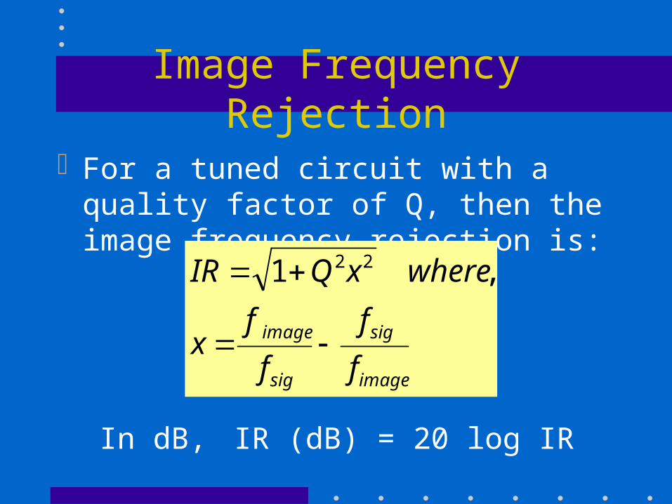
Image Frequency Rejection
For a tuned circuit with a quality factor of Q, then the image frequency rejection is:
image
sig
sig
image
f
f
f
fx
wherexQIR
,1 22
In dB, IR (dB) = 20 log IR
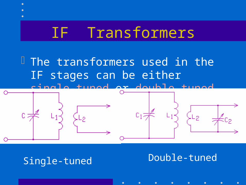
IF Transformers
The transformers used in the IF stages can be either single-tuned or double-tuned.
Single-tuned Double-tuned
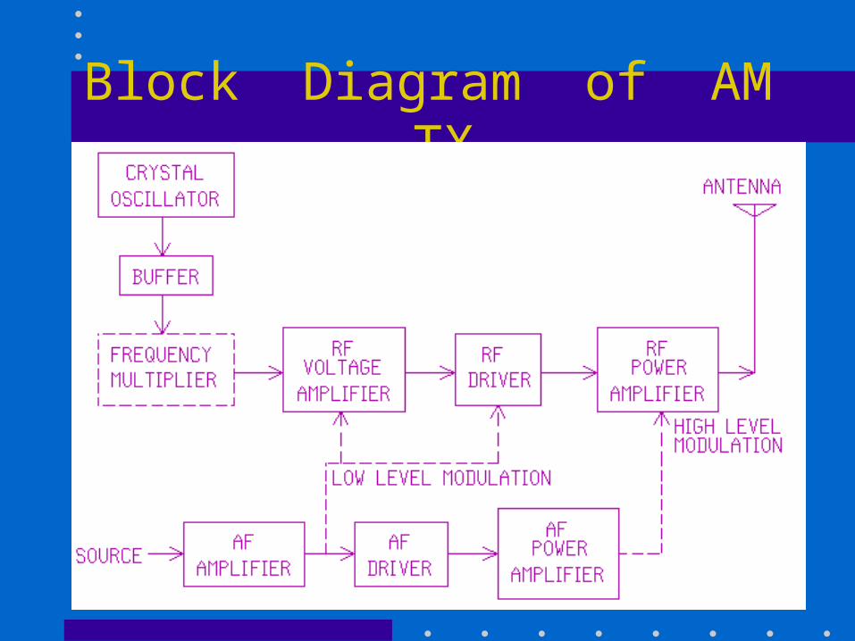
Block Diagram of AM TX
Transmitter Stages
Crystal oscillator generates a very stable sinewave carrier. Where variable frequency operation is required, a frequency synthesizer is used.
Buffer isolates the crystal oscillator from any load changes in the modulator stage.
Frequency multiplier is required only if HF or higher frequencies is required.
Transmitter Stages (cont’d)
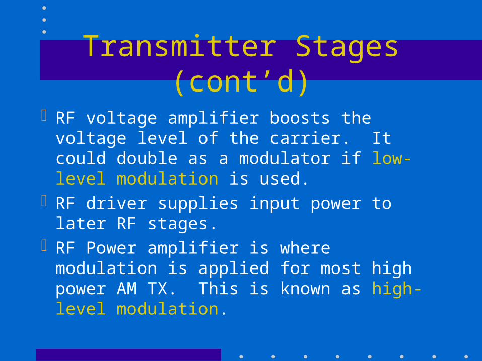
RF voltage amplifier boosts the voltage level of the carrier. It could double as a modulator if low-level modulation is used.
RF driver supplies input power to later RF stages.
RF Power amplifier is where modulation is applied for most high power AM TX. This is known as high-level modulation.
Transmitter Stages (cont’d)
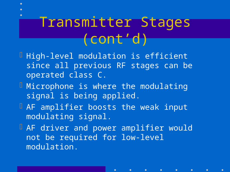
High-level modulation is efficient since all previous RF stages can be operated class C.
Microphone is where the modulating signal is being applied.
AF amplifier boosts the weak input modulating signal.
AF driver and power amplifier would not be required for low-level modulation.
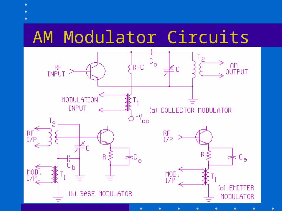
AM Modulator Circuits
Impedance Matching Networks
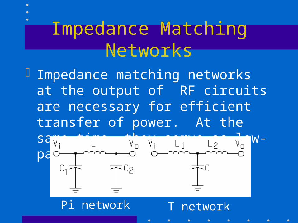
Impedance matching networks at the output of RF circuits are necessary for efficient transfer of power. At the same time, they serve as low-pass filters.
Pi network T network
Trapezoidal Pattern
Instead of using the envelope display to look at AM signals, an alternative is to use the trapezoidal pattern display. This is obtained by connecting the modulating signal to the x input of the ‘scope and the modulated AM signal to the y input.
Any distortion, overmodulation, or non-linearity is easier to observe with this method.
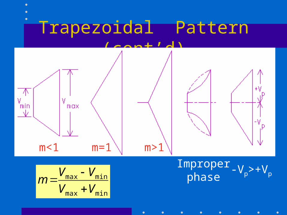
Trapezoidal Pattern (cont’d)
Improperphase
-Vp>+Vp
minmax
minmax
VV
VVm
m<1 m=1 m>1
Suppressed-Carrier AM Systems
Full-carrier AM is simple but not efficient in terms of transmitted power, bandwidth, and SNR.
Using single-sideband suppressed-carrier (SSBSC or SSB) signals, since Psf = m2Pc/4, and Pt=Pc(1+m2/2 ), then at m=1, Pt= 6 Psf .
SSB also has a bandwidth reduction of half, which in turn reduces noise by half.
Generating SSB - Filtering Method
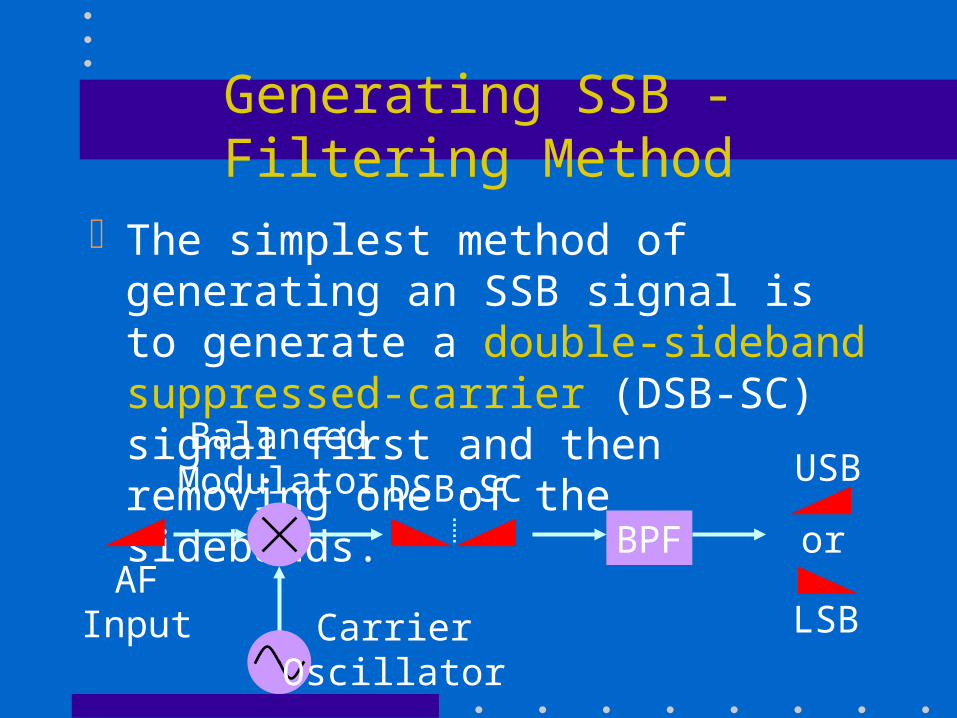
The simplest method of generating an SSB signal is to generate a double-sideband suppressed-carrier (DSB-SC) signal first and then removing one of the sidebands.
BPF orAF
Input
BalancedModulator
CarrierOscillator
DSB-SCUSB
LSB
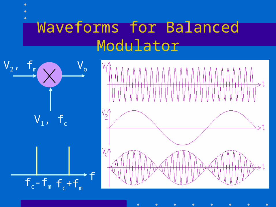
Waveforms for Balanced Modulator
V1, fc
V2, fm Vo
ffc+fm
fc-fm
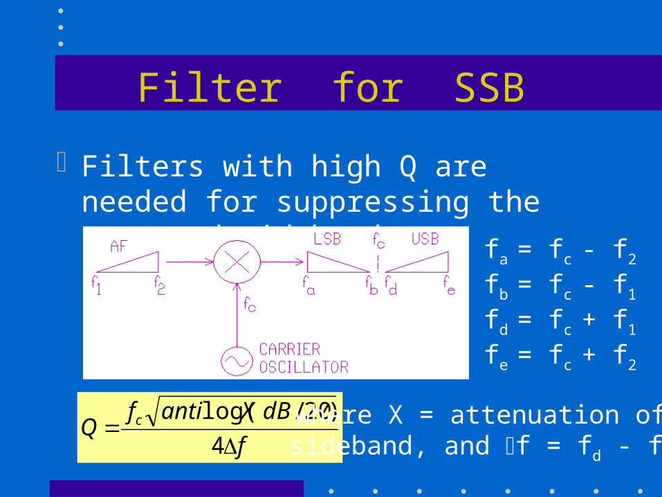
Filter for SSB
Filters with high Q are needed for suppressing the unwanted sideband.
fa = fc - f2
fb = fc - f1
fd = fc + f1
fe = fc + f2
f
dBXantifQ c
4
)20/log( where X = attenuation ofsideband, and f = fd - fb
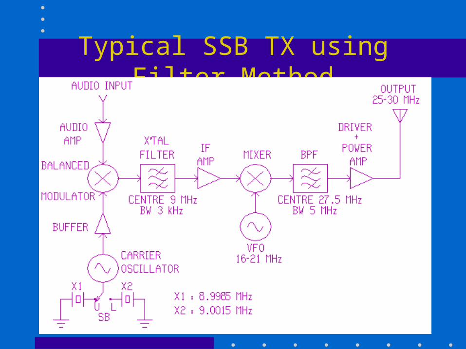
Typical SSB TX using Filter Method