Embed Size (px)
Citation preview

Yanfei Liu
International Journal of Robotics and Automation (IJRA), Volume (2) : Issue (1) : 2011 65
A Robotic Prototype System for Child Monitoring
Yanfei Liu [email protected] Department of Engineering Indiana University – Purdue University Fort Wayne, 46805-1499, US
Abstract
Child monitoring systems can use different technologies, such as camera systems, wireless technology using RFID sensors, and GPS based systems. These systems are capable of remotely reporting the status of the children but not able to take actions based on the interpretation of the scenarios. A robotic child monitoring system has the advantage that it can take actions to warn and possibly protect the child from danger. In this paper we present the design and experimental testing of a robotic child monitoring prototype system. The whole system consists of a Khepera robot, a host computer, the distraction/alarm circuitry and a testing table. The experimental testing results show that this prototype system fulfills the requirement of finding and following the baby prop and also taking certain actions when the baby prop approaches a danger area.
Keywords: Autonomous Robots, Household Robots, Child Monitoring.
1. INTRODUCTION
Different technologies have been used to implement child monitoring systems to release parents from continuous observation of their children. These techniques include camera systems, wireless technology using RFID sensors, and GPS systems. Cooper et al. [1] collected data about the outdoor physical activity of over 1000 children to study their behavior patterns. The data was collected through accelerometers and GPS receivers. Al-Ali et al. [2] described a Kids Tracking System using RFID sensors. The system was designed to track moving children in an area such as a large park or a shopping center. The children to be tracked were given an RFID tag to wear. Several wireless RFID readers were installed in the park. These readers sent the locations of the children to a central station through wireless LANs. Rai et al. [3] described a multiple camera system using FireWire web cameras. One of the potential applications for this system was to track the position of a moving person. The aforementioned systems are examples of three technologies that have been used in child monitoring systems. There has been also research work that combined some of the aforementioned techniques. Jawad et al. [4] presented a child tracking system that used GPS outdoors and RF signals indoors to provide the locations of children. Nakagawa et al. [5] developed a system that used multi-camera system and RFID to monitor children. Based on the information provided from the RFID tags, the parents can choose the camera that will take and transmit the images. Ishikawa et al. [6] described a system that combined an omni-directional camera and a GPS receiver to remotely monitor a child. This system allows the parents to open Google Maps using the position provided by the GPS system. The images transmitted from the omni-directional cameras would compensate for the measurement error of the GPS system. Sampath and Sundaram [7] described a mobile unit that combined an omni-directional camera, a basic health monitoring gadget module, and wireless transceivers to serve as a remote monitoring system for children. Wong et al. [8] proposed a child care system that combined GPS and Bluetooth technologies. The system detects the location of the child with the GPS system and the distance between the child and the parent through received the signal strength indicator (RSSI) from Bluetooth.
Yanfei Liu
International Journal of Robotics and Automation (IJRA), Volume (2) : Issue (1) : 2011 66
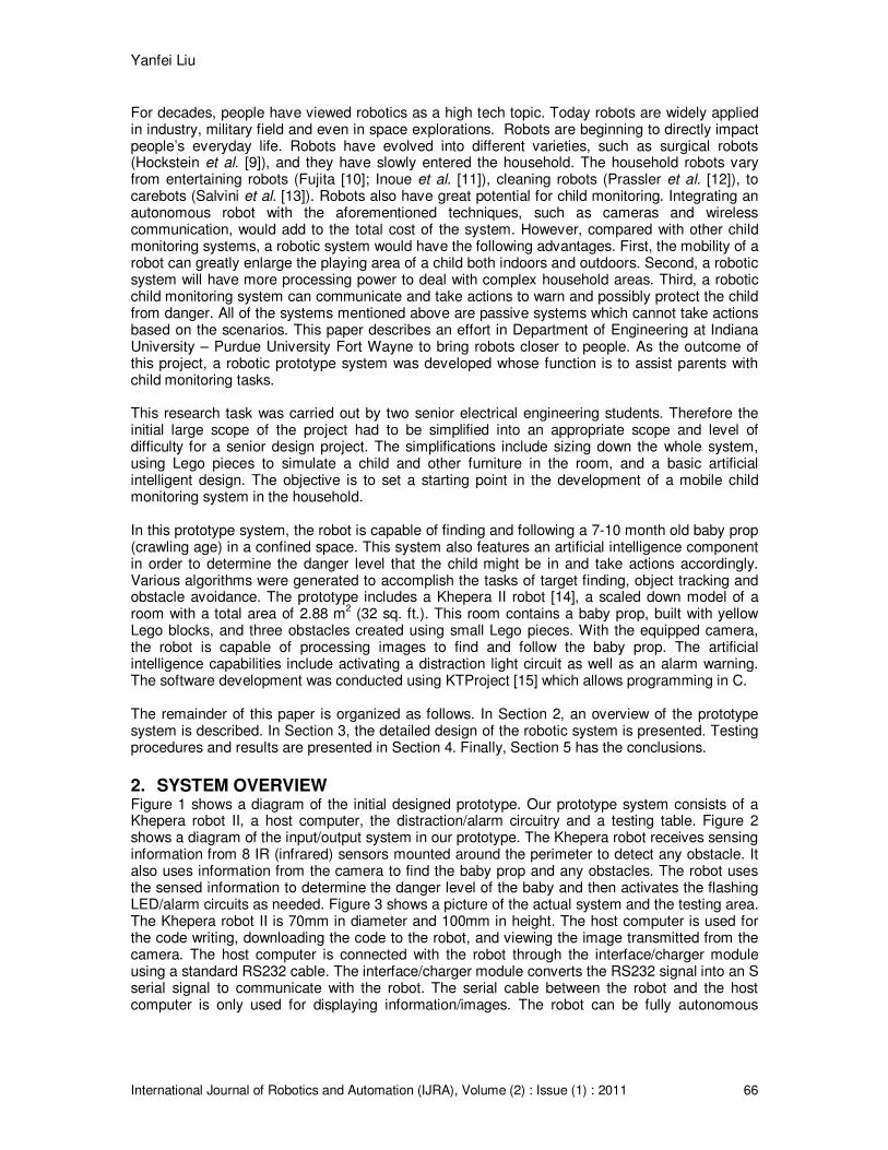
For decades, people have viewed robotics as a high tech topic. Today robots are widely applied in industry, military field and even in space explorations. Robots are beginning to directly impact people’s everyday life. Robots have evolved into different varieties, such as surgical robots (Hockstein et al. [9]), and they have slowly entered the household. The household robots vary from entertaining robots (Fujita [10]; Inoue et al. [11]), cleaning robots (Prassler et al. [12]), to carebots (Salvini et al. [13]). Robots also have great potential for child monitoring. Integrating an autonomous robot with the aforementioned techniques, such as cameras and wireless communication, would add to the total cost of the system. However, compared with other child monitoring systems, a robotic system would have the following advantages. First, the mobility of a robot can greatly enlarge the playing area of a child both indoors and outdoors. Second, a robotic system will have more processing power to deal with complex household areas. Third, a robotic child monitoring system can communicate and take actions to warn and possibly protect the child from danger. All of the systems mentioned above are passive systems which cannot take actions based on the scenarios. This paper describes an effort in Department of Engineering at Indiana University – Purdue University Fort Wayne to bring robots closer to people. As the outcome of this project, a robotic prototype system was developed whose function is to assist parents with child monitoring tasks. This research task was carried out by two senior electrical engineering students. Therefore the initial large scope of the project had to be simplified into an appropriate scope and level of difficulty for a senior design project. The simplifications include sizing down the whole system, using Lego pieces to simulate a child and other furniture in the room, and a basic artificial intelligent design. The objective is to set a starting point in the development of a mobile child monitoring system in the household. In this prototype system, the robot is capable of finding and following a 7-10 month old baby prop (crawling age) in a confined space. This system also features an artificial intelligence component in order to determine the danger level that the child might be in and take actions accordingly. Various algorithms were generated to accomplish the tasks of target finding, object tracking and obstacle avoidance. The prototype includes a Khepera II robot [14], a scaled down model of a room with a total area of 2.88 m
2 (32 sq. ft.). This room contains a baby prop, built with yellow
Lego blocks, and three obstacles created using small Lego pieces. With the equipped camera, the robot is capable of processing images to find and follow the baby prop. The artificial intelligence capabilities include activating a distraction light circuit as well as an alarm warning. The software development was conducted using KTProject [15] which allows programming in C. The remainder of this paper is organized as follows. In Section 2, an overview of the prototype system is described. In Section 3, the detailed design of the robotic system is presented. Testing procedures and results are presented in Section 4. Finally, Section 5 has the conclusions.
2. SYSTEM OVERVIEW
Figure 1 shows a diagram of the initial designed prototype. Our prototype system consists of a Khepera robot II, a host computer, the distraction/alarm circuitry and a testing table. Figure 2 shows a diagram of the input/output system in our prototype. The Khepera robot receives sensing information from 8 IR (infrared) sensors mounted around the perimeter to detect any obstacle. It also uses information from the camera to find the baby prop and any obstacles. The robot uses the sensed information to determine the danger level of the baby and then activates the flashing LED/alarm circuits as needed. Figure 3 shows a picture of the actual system and the testing area. The Khepera robot II is 70mm in diameter and 100mm in height. The host computer is used for the code writing, downloading the code to the robot, and viewing the image transmitted from the camera. The host computer is connected with the robot through the interface/charger module using a standard RS232 cable. The interface/charger module converts the RS232 signal into an S serial signal to communicate with the robot. The serial cable between the robot and the host computer is only used for displaying information/images. The robot can be fully autonomous

Yanfei Liu
International Journal of Robotics and Automation (IJRA), Volume (2) : Issue (1) : 2011 67
when in action. The robot activates the distraction/alarm circuitry using a wireless transmission to the radio base. A testing field was built to simulate a baby’s scaled down playpen area. The field was a table with approximate dimensions of 1.2m X 2.4m (4ft. X 8ft.). There is a red outer marking to indicate the out of bounds area and a blue inner marking to indicate the warning area (Figure 3). The red marking encompasses the playpen and has a total surface area of 1.3m
2 (14sq.ft.). The blue
marking is 5cm to the inside of the red line and it also encompasses the playpen area. Additionally, a white vertical boundary of height 0.3m (1ft) on the table’s perimeter was created as a wall.
FIGURE 1: Robot and host computer configuration.
FIGURE 2: System diagram.
3. DETAILED DESIGN
3.1 Robot Set In our prototype, the robot is the Khepera II [14]. The robot has a Motorola 68331 microcontroller with 512K RAM and flash memory on board. The robot was assembled with the following turrets, mounted in the given order, from bottom to top: Base unit, General I/O turret, Radio turret and the Camera turret. Figure 4 shows the pictures of each individual turret, the assembling order and the final robot. To attach these turrets to the robot base, they have to be placed on the extension

Yanfei Liu
International Journal of Robotics and Automation (IJRA), Volume (2) : Issue (1) : 2011 68
connector with all the pins seated correctly. The serial connection of the radio turret is used by the robot to communicate with the host computer. The K6300 Camera Turret comes equipped with a Freescale MC68331 processor, along with a flash memory. The camera turret holds a V6300 digital CMOS color camera and its optical elements. The color images acquired through this camera are 160 pixels wide and 120 pixels high. A detailed description of the Khepera II robot and the aforementioned turrets can be found in [16].
FIGURE 3: The actual system and testing area.
FIGURE 4: The composition of the Khepera II robot.

Yanfei Liu
International Journal of Robotics and Automation (IJRA), Volume (2) : Issue (1) : 2011 69
3.2 Hardware Design The hardware design includes a flashing lights circuit and an alarm system. The flashing lights circuit is designed to distract the child from going into dangerous situations. Four bright LEDs are placed in the four corners of the room. This guarantees that the baby will see at least one light no matter which direction the baby is facing. The alarm system is used to alert the parents for three different purposes. First, if the robot doesn’t find the baby after searching the entire room, the robot needs to alert the parents. Next, if the robot is trapped between the wall and the baby, i.e. the baby might pick the robot up and the robot has no room to back up, it needs to send an alarm to alert the parents. Finally if the baby is in the out of bounds area the robot needs to notify the parents that the child might be in danger. Figure 5 shows the complete diagram for the LED/alarm circuits. In the next several paragraphs, the function and design of each individual circuit will be briefly described. A more detailed description of these circuits can be found in [17].
FIGURE 5: Complete diagram of the LED/alarm circuits.
The LED/alarm circuits are triggered by the robot sending a signal from the radio turret to the radio base. After the robot sends a signal to the radio base, the same signal is then instantaneously transmitted out from the RS232 port to the radio base. Since the signal goes high for only 10ms, there is not enough time to turn on a transistor and activate necessary hardware components. So, in order to extend the time of the input signal to a few seconds a timer circuit (shown in Figure 5) utilizing a 555 timer IC (integrated circuit) is used.
The output of the timer goes to a 7474 D- flip-flop. This set-up is to properly alternate the circuits (shown in Figure 5) between the LED circuit and the alarm circuit. The Q output of the flip-flop is
reversed back to the D input and the timer output acts as the clock. The Q andQ outputs are
ANDed with the clock. This ensures that only one circuit is ON at any particular time.
In the alarm circuit, a high signal is sent to trigger the transistor to start conducting and thus a current begins to flow from the transformer and through the switch. This current flow causes the normally open switch to close and create a connection. The circuit is completed creating a ground connection to the door chime. A current flows through the encasing, retracting the solenoid. When the pulse stops flowing through the transistor, the current stops flowing, and the solenoid is released quickly, hitting the metal strips, creating a chime.

Yanfei Liu
International Journal of Robotics and Automation (IJRA), Volume (2) : Issue (1) : 2011 70
3.3 Image Processing and Obstacle Avoidance The processor on the camera turret is a VV6300 manufactured by VLSI Vision Limited. The camera has an integrated CMOS (complementary metal oxide semiconductor) color image sensor with an on-chip ADC (analog/digital converter). The image resolution is 120X160 (row x column) and stored in the Bayer pattern color pixel array showed in Figure 6. In this pattern each pixel is divided into red, green and blue values that can range from 0 to 255. From Figure 3 we can see that there are four colors needed to be distinguished, yellow (the baby prop), purple (obstacles), and the blue and red lines on the table. Due to the low quality of the images received from the camera, the colors of the actual objects are distorted. So the filtering ranges of these four colors are experimentally determined. With only one of the color object present in front of the camera, the ranges of red, green and blue values in the Bayer pattern were determined. Results of the filtering ranges for the four colors can be found in [17].
FIGURE 6: Bayer filter pattern
The obstacle avoidance was accomplished via both image processing and the IR sensor readings. The obstacle was first detected by using image filtering. Once an obstacle is found, the robot will keep moving forward and checking the results from the IR sensors located around the robots. Once the IR sensors detect the obstacle, the robot will turn right and move forward for 20cm(max length of the biggest obstacle), then turn left and move forward 10cm(max width of the biggest obstacle), then turn left and go forward 20cm again to reach the same distance as started before the obstacle was reached, and then turn left to face in the same direction as was before the obstacle was reached.
4. TESTING PROCEDURES AND RESULTS
The baby prop was created by stacking up eight Lego blocks and is 3cm long, 1.5cm wide and 7.5cm high. The dimensions of the obstacles are given in Table 1. Figure 7 also shows a picture of the three obstacles.
Obstacle # Length (cm) Height (cm) Width/diameter (cm)
1 7.5 3 0.9 2 10 5 4 3 10 5 0.9
TABLE 1: Dimensions of the obstacles.

Yanfei Liu
International Journal of Robotics and Automation (IJRA), Volume (2) : Issue (1) : 2011 71
Three different scenarios were tested for the prototype system. Each scenario represents one level of complexity of the environment, ranging from no obstacle, only one obstacle to three obstacles.
FIGURE 7: The obstacles.
4.1 Scenario I – no Obstacle In this scenario there were no obstacles placed in the room. During this test the baby prop was present in the room 5 out of the 10 times. Each time the test was conducted the position and direction of the robot was changed. Figure 8 illustrates the approximate positions of the robot and the baby prop during each of the tests. Figure 9 shows a picture of one of the testing positions of the robot and the baby prop. During the first 5 trials the baby prop was not present, and then the baby prop was placed in different locations in the room for the other 5 trials. The testing results are presented in Table 2. Out of the ten tests, only one false result was produced. Errors are produced because the objects in the image become out of focus when the baby prop is more than 60 cm away from the robot.
Baby found Baby not found
No baby present 0 5
Baby present 4 1
TABLE 2: Testing results for scenario I.

Yanfei Liu
International Journal of Robotics and Automation (IJRA), Volume (2) : Issue (1) : 2011 72
FIGURE 8: The locations for the robot and the baby in scenario I
FIGURE 9: The robot and baby prop in scenario I.
4.2 Scenario II – With one Obstacle This setup is of an intermediate difficulty level. Thus, even after the robot has located the baby prop there is an obstacle that the robot has to avoid in order to get to the child. The rectangular box shaped obstacle with dimensions 10 cm long, 5 cm high and 0.9 cm wide was placed between the robot and the baby prop. Also, the robot has to use the camera to detect whether the obstacle is present or not. The test was performed 5 times with the obstacle present and 5 times with the obstacle absent. Figure 10 illustrates the approximate positions of the objects during the tests. Figure 11 shows a picture of the testing scenario. Table 3 shows the testing results of whether the obstacle was found. Out of ten tests, only two false results were produced. During each test it is important to determine whether the robot maintains its course or deviates

Yanfei Liu
International Journal of Robotics and Automation (IJRA), Volume (2) : Issue (1) : 2011 73
from it. This determination is needed to assert whether the robot will reach the baby prop after it has passed around the obstacle. Such situation was also tested in this scenario. Once the robot has successfully avoided the obstacle it still needs to determine the baby prop’s location in the room and reach it successfully. Table 4 shows the results of whether the robot can reach the baby. Out of ten tests, there were two instances when the robot couldn’t reach the baby prop. This is due to two reasons. First, the two motors on the robot do not always move at the same speed. The left motor turns faster than the right motor all the time. This speed difference causes the robot to compute inaccurate results regarding the distance traveled across the table. Second, the low quality camera creates difficulties for the vision algorithm to distinguish between the color of the obstacle, the baby prop, and the blue or red borders. This problem causes the robot to sometimes assume that the baby prop or the boundary lines is an obstacle which make the robot go around the baby prop instead of following it around the room.
FIGURE 10: The top view of scenario II.
FIGURE 11: Testing environment in scenario II.

Yanfei Liu
International Journal of Robotics and Automation (IJRA), Volume (2) : Issue (1) : 2011 74
Obstacle found Obstacle not found
Obstacle present 5 0
Obstacle absent 2 3
TABLE 3: Testing results of finding the obstacle in scenario II.
Reached baby Didn’t reach the baby
Obstacle present 5 0
Obstacle absent 3 2
TABLE 4: Testing results of reaching the baby prop in scenario II.
4.3 Scenario III – Complex Environment This is the most difficult situation for the robot. Three obstacles were placed between the robot and the baby prop. Each time the test was run the location of the obstacles stayed the same. But sometimes the obstacle exactly in front of the child was switched with another of a different size and shape. Figure 12 shows a sample layout of one of the test variations. Two out of the 5 times, obstacle 3 was in front of the baby prop. Two times obstacle 2 was present and finally once obstacle 1 was present. The rest of the five times the test was run, there was no obstacle between the robot and the baby. Figure 13 shows a picture of the testing scenario. Table 5 shows the testing results of whether the obstacle was found. Out of ten tests, only one produced a false result. Table 6 shows the results of whether the robot can reach the baby prop. Out of ten tests, there was only one case when the robot couldn’t reach the baby prop. The reason is similar as the one for scenario II.
FIGURE 12: Top view of scenario III.

Yanfei Liu
International Journal of Robotics and Automation (IJRA), Volume (2) : Issue (1) : 2011 75
FIGURE 13: Picture of the testing environment in scenario III.
Found Obstacle Obstacle not found
Obstacle present 4 0
Obstacle absent 1 5
TABLE 5: Testing results of finding the obstacle in scenario III.
Reached Baby Didn’t reach the baby
Obstacle present 4 0
Obstacle absent 5 1
TABLE 6: Testing results of reaching the baby in scenario III.
4.4 Distraction and Alarm Circuits Once the robot finds the baby prop, the robot should follow it around the room. If the baby prop gets close to the blue line the robot should send a signal to distract the baby prop with the help of the flashing LEDs. Also, if the baby prop gets into the out of bounds area the robot should send another signal and activate the alarm to alert the parents. Table 7 and 8 show the results.
Lights on Lights off
Within range 3 0
Out of range 2 5
TABLE 7: Testing results of the LED circuit.
Alarm on Alarm off
Within range 4 1
Out of range 1 4
TABLE 8: Testing results of the alarm circuit.
Other experiments were conducted to test the system’s capability. These experiments include the estimation of the camera’s field of view, the infrared (IR) sensor’s capability and the autonomous behavior of the robots. A detailed description of all of these experiments and the software design can be found in [17].

Yanfei Liu
International Journal of Robotics and Automation (IJRA), Volume (2) : Issue (1) : 2011 76
5. CONCLUSIONS In this paper, the design and experimental testing of a robotic child monitoring prototype system is presented. The whole system consists of a Khepera robot, a host computer, the distraction/alarm circuitry and a testing table. The design of each component was described in detail. Compared with the existing passive child monitoring systems, our system does not require the child to wear any sensor, which means it’s safer. Also, our system can warn the parents when the child is in danger. With further development using a more advanced robotic platform, the system can even take actions to prevent the children from danger. Human interactive systems are always challenging; this system is only a prototype which aims at shedding some lights on a child monitoring robotic system. Therefore it has limitations and drawbacks. For example, the low quality of the image sensor affects the performance in scenarios where more color objects are present. Therefore it is suggested that a better quality camera be used when this type of system is adopted in other robots. Also one robot might not be enough when the environment is more complex than what was experimented in our system. For future work, a network of robots needs to be considered for better performance.
6. REFERENCES 1. A. Cooper, A. Page, B. Wheeler, M. Hillsdon, P. Griew, and R. Jago, “Patterns of GPS
measured time outdoors after school and objective physical activity in English children: the PEACH project,” International journal of Behavioral/Nutrition and Physical Activity 2010, 7:31
2. Al-Ali, A.R.; Aloul, F.A.; Aji, N.R.; Al-Zarouni, A.A.; Fakhro, N.H.; “Mobile RFID Tracking System,” In Proceedings of the 3rd International Conference on Information and Communication Technologies (ICTTA): From Theory to Applications, April 7-11, 2008
3. P. Rai, K. Tiwari, P. Guha, A. Mukerjee, “A Cost-effective Multiple Camera Vision System
using. FireWire Cameras and Software Synchronization,” In Proceedings of the 10th Annual International Conference on High Performance Computing (HiPC 2003)
4. S. Jawad, A. M. Yousef, B. Al-Shagoor, “A Multipurpose Child Tracking System Design and
Implementation,” International Journal of Soft Computing Applications, Issue 4 (2009), pp. 57-68.
5. S. Nakagawa, K. Soh, S. Mine, and H. Saito, “Image Systems Using RFID Tag Positioning
Information,” NTT Tech Rev, Vol.1, NO.7, pp.79-83, 2003 6. T. Ishikawa, K. Yamazawa, T. Kurata, and N. Yokoya, “Mobile Omnidirectional Monitoring
System for Remote Personal Security,” In Proceedings of the 4th International Conference on Collaboration Technologies, August 2008
7. D. Sampath and S. Sundaram, “Telecommunication system for remote monitoring and
access in child care,” in 2008. IET International Conference on Wireless, Mobile and Multimedia Networks, pp. 81-84
8. Kok Sun Wong; Wei Lun Ng; Jin Hui Chong; Chee Kyun Ng; Sali, A.; Noordin, N.K, “GPS
based child care system using RSSI technique,” in 2009 IEEE 9th Malaysia International Conference on Communications (MICC),, pp. 899-904.
9. N. G. Hockstein, , C. G. Gourin, , R. A. Faust, and D. J. Terris, “A history of robots: from
fiction to surgical robotics,” Journal of Robotic Surgery, Vol. 1, No. 2, pg. 113-118, 2007

Yanfei Liu
International Journal of Robotics and Automation (IJRA), Volume (2) : Issue (1) : 2011 77
10. M. Fujita, “On Activating Human Communications with Pet-Type Robot AIBO,” Proceeding of IEEE, Vol. 92, No. 11, pg. 1804-1813, 2004
11. H. Inoue, and H. Miagoshi, “Behavior Evolution of Pet Robots with Human Interaction,” 2007
Second International Conference on Innovative Computing, Information and Control, pg. 23-23
12. E. Prassler, A. Ritter, C. Schaeffer, and P. Fiorini, “A Short History of Cleaning Robots,”
Autonomous Robots, Vol. 9, No. 3, pp. 211-226., 2000 13. P. Salvini, C. Laschi, and P. Dario, “Roboethics in biorobotics: discussion of case studies,”
International Conference on Robotics and Automation (ICRA 2007) Workshop on Robo-Ethics, Rome, Italy, 2007
14. K-team home page, http://www.k-team.com/mobile-robotics-products/khepera-ii, last
accessed December 2010 15. Khepera II programming manual (version 1.1, March 2000), K-team http://ftp.k-
team.com/khepera/documentation/Kh2ProgrammingManual.pdf, last accessed December 2010
16. Y. Liu, C. Griffith, and P. Reddy, “Baby Bot, a Child Monitoring Robotic System,” in Proceedings of the ASEE Illinois-Indiana and North Central Joint Section Conference, Fort Wayne, IN, USA, March 2006
17. C. Griffith, and P. Reddy, “The BabyBot – Robotic Child Monitoring System,” Capstone
Senior Design Report II, http://www.engr.ipfw.edu/capstone/sd_2_fall06/Baby_Bot_FINALReport.pdf , last accessed December 2010


![IEEE TRANSACTIONS ON AUTOMATION SCIENCE …lowkh/pubs/tase2015.pdfsystem to be enhanced by deploying robotic shared vehicles (e.g., General Motors Chevrolet EN-V 2.0 prototype [13])](https://img.pdfslide.us/doc/110x75/5f47268a49d46a39143d6423/ieee-transactions-on-automation-science-lowkhpubs-system-to-be-enhanced-by-deploying.jpg)

![Prototype of Robotic Ankle-Foot Prosthesis with Active ... · fuzzy logic and expert systems), artificial intelligence and control based on the level of coordination [4] [5]. Linear](https://img.pdfslide.us/doc/110x75/605c7af1ee7c495bd16b0cc5/prototype-of-robotic-ankle-foot-prosthesis-with-active-fuzzy-logic-and-expert.jpg)
![Model identification for impact dynamics of a ...microsystems.engin.umich.edu/wp-content/uploads/sites/141/2017/06/2012... · frequency of prototype micro-robotic leg joints [15]](https://img.pdfslide.us/doc/110x75/5e1cb9e144a1d932e53f0689/model-identification-for-impact-dynamics-of-a-frequency-of-prototype-micro-robotic.jpg)