Embed Size (px)
Citation preview

Electrical Engg.
Get Homework/Assignment Done
Homeworkping.comHomework Help https://www.homeworkping.com/
Research Paper helphttps://www.homeworkping.com/
Online Tutoringhttps://www.homeworkping.com/
click here for freelancing tutoring sites
DEDICATED TO
MY
BELOVED PARENTS
AND
BABA
GITS, Udaipur 1
Electrical Engg.
CERTIFICATE
Certificate that the work entitled "SIMULATION STUDY
OF HVDC SYSTEM" has been carried out by SHAILENDRA
SINGH BHATI under my supervision and has not been submitted
elsewhere for the award of degree.
Internal Examiner
GITS, Udaipur 2
Electrical Engg.
DECLARATION
The thesis "Simulations Study of HVDC SYSTEM" has
been examined on 19-06-2004 as partial fulfillment of Master of
Technology in Power Electronics.
Internal Examine
Head of the Department
Dr. K.K. RayProf. & Head, EEE Dept.
VIT, Vellore
GITS, Udaipur 3
Electrical Engg.
ACKNOWLEDGEMENTS
First of all I thank THE ALMIGHTY for bestowing his blessings on
me so that I am able to complete this project successfully.
1 am very much indebted and thankful to Dr. S. Nyati (Ph.D.. Manitoba
University, Canada) and Prof. C.S.Upadhyay, MNIT, Jaipur, for having given
me a wonderful opportunity to work under them for this project work.
I am thankful to Chief Engineer and Senior Engineers at HVDC
project, Dadri to work in that friendly environment under their guidance.
1 am also thankful to Mr.V.Velmurugan, M.E.. Lecturer, Electrical &
Electronics for his guidance and valuable suggestions and also for the help
extended whenever needed and for constant encouragement.
I also take this opportunity to sincerely thank Dr. T. Jayafoarathi,
Project co-ordinator, for having confidence in me and allocating this work.
I take this opportunity to sincerely thank Dr. K.K.Ray, Head of
Department of Electrical & Electronics Engineering, for help and constant
encouragement.
I also express my gratitude to all the faculties for their timely-help and
assistance.
I express my immense gratitude to our Chancellor. Sri. G. Visvanathan
and our Principle. Dr. Samuel.A.Anand. who always cared for us from the
beginning of course by providing us with all facilities.
Last but not least. I express my heartful thanks for all the staff
members and my friends for their kind help.
GITS, Udaipur 4
Electrical Engg.
ABSTRACT
The project "SIMULATION STUDY OF HVDC SYSTEM" deals with
the PSCAD/EMTDC based design and testing of a High Voltage Direct Current
(HVDC) system operating with weak AC systems. It also incorporates the
VDCOL unit and Mater power control feature.
This scheme has the advantage of wide range of power control and ability
to recover from the fault conditions. The modeled system takes the power input
from the user and controls are produced accordingly. The modeled system
provides a starting point for:
(a) Educators teaching HVDC transmission courses, and
(b) For utility planners to develop their own low-cost
dedicated simulators for training purposes
Modeling details for the following subsystems are provided:
DC converters including representation on snlibber circuits,
DC controls for rectifier and inverter,
AC system including filters,
DC system including filers,
VDCOL unit.
Mater power controls
To validate the performance of the system and DC controllers. the HVDC
system is tested under 11 types of typical AC-DC system faults and ail faults
are cleared by the system itself.
GITS, Udaipur 5
Electrical Engg.
Further it also aims to study and simulate Delhi-Rihand HVDC project and
during the investigation few operational problems like failures of cotter bolts on
HVDC link, flash over m DC yard at Dadri converter station, frequent operation
of an on load tap changer and switching of filter banks, which affects the
performance of the link, were observed. Further to ensure better performance
and to improve availability and reliability of system, these problems were
properly analyzed and suggestions have been given for modification of system.
GITS, Udaipur 6
Electrical Engg.
CONTENTS
TOPIC PAGE. NO.
CHAPTER 1 INTRODUCTION
1.1 General Introduction 1
1.2 HVDC Installations in World today 2
1.3 Rationale for choosing HVDC 2
1.4 Introduction of my work 3
1. Highlights 3
CHAPTER-II FEATURES OF DC TRANSMISSION
2.1 Advantage of DC Over AC 5
2.2 Basic DC Transmission System 6
CHAPTER-III HVDC TRANSMISSION TECHNOLOGY
3.1 Types Of DC Link 9
3.2 Component Of a DC Transmission Line 10
3.3 Basic Principles Of HVDC Control
3.3.1 Types Of DC Control 13
3.3.2 Rectifier And Inverter Characteristics 14
3.3.3 Voltage Dependent Current Order.Limit 15
3.4 Power Control 16
3.5 Review And Scope Of Present Work ** 16
CHAPTER-IV SIMULATION OF HVDC SYSTEM
4.1 Digital Dynamic Simulation 22
4.2 Advantage Of Digital Simulation 23
4.3 PSCAD/EMTDC Simulation Tool 23
4.4 Modeling Of HVDC System4.4.1 Power System4.4.2 Control System
2325
4.5 Modeling Of AC system Strength
4.6 Harmonic Instability
4.7 Frequency Scanning Technique
CHAPTER-V TRANSIENT BEHAVIOUR OF HVDC SYSTEM 42
CHAPTER VI THE RJHAND-DELHI PROJECT
6.1 Introduction 111
GITS, Udaipur 7
Electrical Engg.
6.2 Description of HVDC Terminal 111
6.3 Control Principles 115
6.4 Protection Scheme 116
6.5 Operational Performance 118
6.6 Transfer between metallic and ground return 118
6.7 System During Commutation Failure 122
CONCLUSIONS
APPENDICES
BIBLIOGRAPHY
GITS, Udaipur 8
Electrical Engg.
LIST OF TABLE
TABLE NO. TITLE PAGE NO.
4.1 AC SUPPLY SYSTEM 3 1
4.2 AC FILTER PARAMETERS 32
4.3 CONVERTER TRANSFORMER PARAMETERS 33
4.4 CONVERTER BRIDGE PARAMETERS 34
4.5 GATE FIRING UNIT 35
4.6 DC LINE PARAMETERS 36
4.7 RECTIFIER CONTROL SYSTEM 37
4.8 VDCOL CHARACTERISTICS 38
4.9 INVERTER CONTROL SYSTEM 39
6.1 SPECIFICATION OF DELHI-RIHAND SYSTEM
GITS, Udaipur 9
Electrical Engg.
LIST OF FIGURES
FIGURE NO. TITLE PAGE NO.
1.1 HVDC TRANSMISSIONS AROUND THE WORLD
IN THE YEAR 2000
4
2.1 ELEMENTARY DC TRANSMISSION SYSTEM 8
3.1 DC LINK CONFIGURATION 18
3.2 COMPONENTS OF HVDC TRANSMISSION
SYSTEM
19
J.J CONVERTER CONTROL CHARATERISTICS 20
3.4 VDCOL CHARACTERISTICS 21
3 5 OPERATING POINT WHEN DELIVERING 20% OF
RATED POWER
16
4.1 AC SUPPLY NETWORK 31
4.2 AC FILTERS 32
4.3 CONVERTER TRANFORMERS JJ
4.4 CONVERTER BRIDGES 34
4.5 GATE FIRING UNIT 35
4.6 DC LINEMOQEI 36
4.7 RECTIFIER CONTROL SYSTEM 37
4.8 INVERTER CONTROL SYSTEM 39
4.9 MASTER POWER CONTROL 40
4.10 FREQUENCY SCANNING METHOD 41
GITS, Udaipur 10
Electrical Engg.
NOMENCLATURE
α − Delay Angle for Rectifier
γ − Extinction Angle for Inverter
Ω − Ohms
αmin - Minimum Delay Angle for Rectifier
γ min - Minimum Extinction angle for Inverter
AC - Capacitance
DC - Direct Current
EMTDC - Electro Magnetic Transients for Direct
Current Transmission
ESCR - Effective Short Cirucit Ratio
Eth - Thevenin Voltage
F - Frequency
FACTS - Flexible AC transmission system
GFU - Gate Firing Unit
HVDC - High Voltage Direct
Hz - Hertz
Im - Current Margin
IMIN - Minimum Current
IOLIM - Current Order Limit
ITP - Independent Transmission Project
KV - Kilovolts
GITS, Udaipur 11
Electrical Engg.
L - Inductance
mH - Milli henry
MVA - Mega volt ampere
PSCAD - Power System Computer Aided Design
Q - Reactive power
RMS - Root Mean Square
SCMVA - Short circuit mega volt- ampere
SCR - Short circuit ratio
SVC - Static var compensator
VCO - Voltage Controller Oscillator
VDCOL - Voltage Dependent Current Order Limit
VCD - Voltage control device
Zth - Thevenin Impedance
GITS, Udaipur 12
Electrical Engg.
INTRODUCTION
1.1 GENERAL INTRODUCTION
It has been widely documented in history of electricity industry, that the
first commercial electricity generated (by Thomas alva Edison) was direct
current (DC) electrical power. The first electricity transmission systems were
also direct current systems. However, DC power at low voltage could not be
transmitted over long distances, thus giving rise to high voltage alternating
current (AC) electrical system. Nevertheless, with the development of the high
voltage valves, it was possible to once again transmit DC power at high
voltages and over long distances giving rise to HVDC transmission system.
Some important milestones of DC transmission technology are
Hewith mercury-vapour rectifier, which appeared in 1901
Experiments with thyratron in America and mercury arc valves in Europe
before1940.
First commercial HVDC transmission, Gotland in Sweden in 1954
Highest DC transmission voltage (+/- 600 KV) in Itaipu, Brazil, 1984
First active DC filters for outstanding filtering performance in 1994
First capacitor commutated converter(CCC) in Argentina-Brazil
interconnection, 1998
First voltage source converter for transmission in Gotland, Sweden, 1999
GITS, Udaipur 13
Electrical Engg.
"HVDC light" transmission interconnection that has linked the Queensland
and New South Wales energy markets in the year 2000
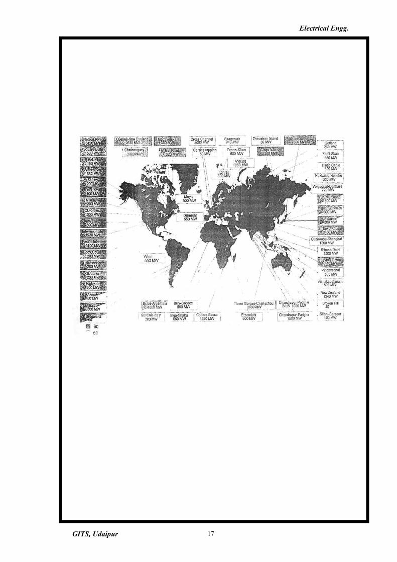
1.2HVDC INSTALLATIONS IN WORLD TODAY [1]
Since the first commercial installation in 1954 a large number of HVDC
transmission systems have been installed around the world. Figure 1.1 shows by
region, the different HVDC transmissions around the world.
1.3 RATIONALE FOR CHOOSING HVDC
There are many different reasons as to why HVDC was chosen in above
projects. A few of the reasons in selected projects are
In Itaipu, Brazil ,HVDC was chosen to supply 50 Hz power into a 60 Hz
system and to economically transmit large amount if hydro power (6300
MW) over large distances (800 KM)
In Leyte-Luzon project in Philippines, HVDC was chosen to enable supply
©f-bulk geothermal power across an ibiand mtercomrectiorr,ai"id to improve
stability to the Manila AC network
In Rihand-Delhi project in India, HVDC was chosen to transmit bulk
(thermal) power (1500 MW) to Delhi, to ensure minimum losses, least
amount right of way and better stability and control.
In Garabi, -an independent transmission project (ITP) transferring power
from Argentina to Brazil, HVDC back to back system was chosen to ensure
supply of 50 Hz bulk power to a 60 Hz system under a 20 year power supply
contract.
In Gotland, Sweden, HVDC was chosen to connect a newly developed wind
power site to main city of Visby, in consideration of environmental
sensitivity of the project area and improve power quality.
In Queensland, Australia, HVDC was chosen in an ITP to interconnect two
independent grids, ensure very low environmental time and reduce
construction
GITS, Udaipur 14
Electrical Engg.
GITS, Udaipur 15
Electrical Engg.
1.4 INTRODUCTION ON MY WORK
The dynamic simulation of HVDC system by digital computer was
first suggested by N. G. Hingorani [3] in 1970.
The growth of HVDC, SVC, and FACTS related power electronic
equipment has advanced the development of electromagnetic transient
simulation packages based onEMTDC[4,5].
These and other simulation packages offer possibility of developing low
cost digital simulators, which can be used for
Training students, operators and engineers on HVDC system operation.
Development of operating control strategies.
Validation of system performance with specific system projects.
1.5 HIGHLIGHTS
1. A basic generic model of HVDC system operating with weak AC systems has been
modeled using EMTDC.
2. The model provides the"basic building blocks found in typical HVDC system.
3. A voltage dependent current order limit unit is developed which provides the
reference to the current controller after 50% drop in DC voltage.
4. A master power control unit is developed which provides current order to current
controller.
5. To demonstrate the dynamic behavior of typical HVDC system, 11 disturbances
and faults were developed and typical results have been presented. These tests
demonstrate the ability of the DC system, the control and protection system tc
recover from such faults.
GITS, Udaipur 16
Electrical Engg.
GITS, Udaipur 17
Electrical Engg.
2.0 FEATURES OF DC TRANSMISSION [6,7]
The development of high power, high voltage electronic converters has made it
possible to transmit and control large blocks of power using direct current. Direct-
current transmission offers unique features that complement the characteristics of
existing AC networks.
2.1ADVANTAGES OF DC OVER AC
1. DC power can be controlled more quickly. For example, power in megawatt range
can be reversed in a DC line in less than one second. This feature makes it useful to
operate DC transmission lines in parallel with existing AC networks. When
instability is about to occur (due to disturbance on AC system), the DC power can
be changed in amplitude to counteract and dampen out power oscillations.
2. DC power can be transmitted in cables over great distances. The capacitance of
the cable limits AC power transmission to few tens of kilometers. Beyond this
limit, the reactive power generated by cable capacitance exceeds the rating of the
cable itself. Because capacitance does not come into play under steady state DC
conditions, there is theoretically no limit to the distance that power may be carried
this way. As a result, power can be transmitted by cable under large bodies of
water, where the use of AC cables is unthinkable. Furthermore, underground DC
cable may be used to deliver power into large urban centers.
3. The AC power can be transmitted between centers operating at the same frequency
only. Furthermore, the power transmitted depends upon line reactance and phase
angle between the voltages at each end of the line. But when power is transmitted
by DC.frequencies and phase angles do not come into come into picture, and the
line reactance does not limit the steady state power flow. This also means that
power can be transmitted over great distances by using DC.
4. At the opposite extreme of great distance are back-to-back converters, which
interconnect large adjacent AC systems with a DC transmission line that is only
few kilometers long. Back to Back converters enable two systems to operate at
their respective frequencies and phase angles. As a result, disturbances on one
system do not destabilize the other system. Furthermore, the power flow between
the systems can be modified and even reversed in a matter of milliseconds.
GITS, Udaipur 18
Electrical Engg.
2.2 BASIC DC TRANSMISSION SYSTEM
A DC transmission system consists basically of a DC transmission line
connecting two AC systems. A converter at one end of the line converts AC power
into DC power while a similar" converter at the other end reconverts the DC power
into AC power. One converter acts therefore as rectifier, the other as an inverter. The
DC transmission is represented by the circuit shown in figure 2.1.
Converter 1 is a 3-phase, 6-pulse rectifier that converts the AC power of line 1
into DC power. The DC power is carried over a 2-conductor transmission line and
reconverted to AC power by means of converter 2, acting as an inverter. Both
rectifier and inverter are line commutated by the respective line voltages to which
they are connected. Consequently, the networks can function at entirely different
frequencies without effecting the power transmission between them. Power flow may
be reversed by changing the firing angles oti and CC2, so that converter 1 becomes an
inverter and converter2 becomes a rectifier. Changing the angles reverses the
polarities of the conductors, but the direction of current flow remains the same. This
mode of operation is required because thyristors can conduct only in one direction.
The DC voltages Edi and Ed2 at each converter station are identical, except
for the IR drop in the line. Due to the high voltages encountered in transmission lines,
.each thyristor is composed of several thyristors connected in series and such a group
of thyristors is often called a valve.
GITS, Udaipur 19
Electrical Engg.
GITS, Udaipur 20
Electrical Engg.
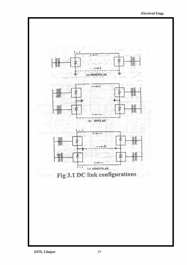
3.1 TYPES OF DC LINKS [7]
HVDC links may be broadly classified into the following categories:
1)Monopolar links
2)Bipolar links
3)Homopolar links
The basic configurations of monopolar link, bipolar link, and homopolar
link are shown in figure 3.1
The monopolar link uses one conductor, usually of negative polarity.
Cost considerations often leads to the use of such systems, particularly for
cable transmission. This type of configuration may also be the first stage in
development of bipolar system. Instead of ground return, a metallic return may
also be used in situations where the earth resistivity is too high or possible
interference with underground/underwater metallic structures is objectionable.
The conductor forming the metallic return is at low voltage.
The bipolar link has two conductors one positive and another negative.
Each terminal has two converters of equal rated voltage, connected in series on
DC side. The junctions between the converters are grounded. Normally, the
currents in the two poles are equal, and there is no ground current. The two
poles can operate, independently. If one pole is isolated due to fault on its
conductor, the other pole can operate with ground and thus carry half the rated
load or more by using the overload capabilities of its converters and line.
The homopolar link has two or more conductors, all having the same
polarity. Usually a negative polarity is preferred because it causes less radio
interference due to corona. The return path for such a system is through ground.
When there is fault on one conductor the entire converter is available for
feeding the remaining conductors which, Wing same overload capability and
can carry more than the normal power.
GITS, Udaipur 21
Electrical Engg.
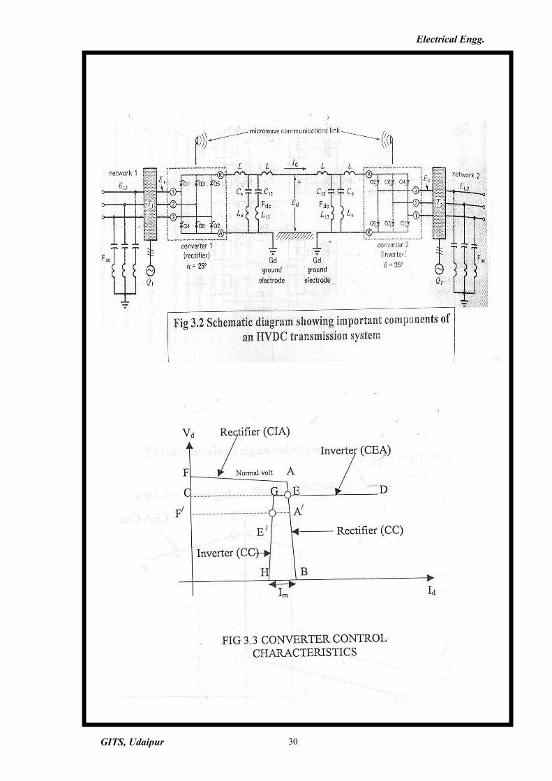
3.2 COMPONENTS OF A DC TRANSMISSION LINE [6]
In order to function properly, a DC transmission system must have
auxiliary components, in addition to the basic converters. Referring to fig.3.2
the important components are
1)DC line inductors (L)
2) Harmonic filters on DC side (FdC)
3)Converter transformers (Ti,T2)
4)Reactive power source (Qi,Ch)
5)Harmonic filters on AC side (Fac)
6)Microwave communication link between the converter stations
7)Ground electrodes (Gd)
The need for these components is explained in the following sections
INDUCTORS AND HARMONIC FILTERS ON DC SIDE
Voltage harmonics are produced on DC side of both the rectifier and
inverter. They give rise to 6th and 12th harmonic currents, and such currents, if
allowed to flow over the DC line could produce serious noise on telephone
lines. Consequently, filters are required to prevent the currents from flowing
over the line. The shunt filters are tuned respectively to short-circuit 6th
harmonic currents to ground.
The inductor L prevents the DC line current from increasing too rapidly
if a line fault occurs.
CONVERTER TRANSFORMERS
The basic purpose of the converter transformer on the rectifier side is to
transform network voltage to yield the AC voltage required by the converter.
Three-phase transformers connected in either in wye-wye or wye-delta are
GITS, Udaipur 22
Electrical Engg.
used. A lower voltage tertiary winding is sometimes used for direct connection
to a source of reactive power.
The DC line voltage is kept essentially constant from no load to full
load. Furthermore to reduce the reactive power absorbed by the converter,
firing angle a should be kept small. This means the ratio between the AC input
and DC voltage output of the converter is essentially fixed. Because DC voltage
is constant, it follows that AC voltage must also be constant.
Unfortunately, the network voltage may vary significantly throughout
the day. Consequently, the converter transformer on rectifier side is equipped
with taps so that variable input voltage will give reasonably constant output
voltage. The taps are switched automatically by the motorized tap changer
whenever the network voltage changes for significant length of time. For the
same reasons taps are needed on the converter transformers on the inverter
side.
The same general remarks are applied to the inverter side of the
transmission line.
REACTIVE POWER SOURCE
The reactive power Q absorbed by the converters must be supplied by the
AC network or by local reactive power source. Because the active power
transmitted varies throughout the day, the reactive source must also be varied.
Consequently, either variable static capacitors or a synchronous capacitor are
required.
HARMONIC FILTERS ON THE AC SIDE
Three phase, 6-pulse converters produce 5th, 7th, 11 ,13 (and higher)
current harmonics on the AC side. For the reasons for telephonic interference,
these currents must not be allowed to flow over the AC lines. Consequently, the
currents are bypassed through low impedance filters connected between 3-
phase AC lines and ground. On a 50 Hz network, each filter is composed of
series resonant IX circuits tuned respectively to 250,350,550, and 650 Hz./
GITS, Udaipur 23
Electrical Engg.
At 50 Hz these LC circuits are almost entirely capacitive. Consequently
they
also .furnish part of reactive power 0 absorbed by each converter.
COMMUNICATIONS LINK
In order to control the converters at both ends of the line, a communication
link between them is essential.. For example, to maintain the current margin AI, the
inverter at one end of the line must know the rectifier current setting Ii. This
information is continually relayed by a high speed communication link between the
two converters.
GROUND ELECTRODES
Direct currents in the ground have a corrosive effect on pipes, cables and
metallic structures. The actual ground electrode is usually located several kilometers
from the converter station to ensure that the ground currents create no local problem
around the station.
3.3 BASIC PRINCIPLES OF IIVDC CONTROL [7]
An HVDC system is highly controllable. Its effective use depends on
appropriate utilization of this controllability to ensure desired performance of
the power system.
3.3.1 BASIC MEANS OF CONTROL
The direct voltage at any point on the line and the current (or power) can be
controlled by controlling the internal voltages (Vdorcosa) and (Vdoicosy). This
is accomplished by grid control or control of the AC voltage through tap
changing of converter transformer.
Grid control, which is rapid (1 to 10 ms), and tap changing, which is
slow (5 to 6 s per step), are used in complementary manner. Grid control is used
GITS, Udaipur 24
Electrical Engg.
initially for rapid action, followed by tap changing to restore the converter
quantities, (a for rectifier and y for inverter) to their normal range.
Power reversal can be obtained by reversal of polarity of direct voltages
at both ends.
3.3.2 TYPICAL RECTIFIER AND INVERTER
CHARACTERISTICS
The rectifier maintains constant current by changing a. However, a
cannot be less than its minimum value αmin. Once αmin was reached, no
further voltage increase is possible, and the rectifier will operate at constant
ignition angle (CIA). Therefore, the rectifier characteristic has really two
segments (AB and FA) as shown in figure 3.3. The segment FA corresponds to
minimum ignition angle and represents the CIA control mode, the segment AB
represents the normal constant current (CC) control mode.
In practice, the constant current characteristic may not be truly vertical,
depending on the current regulator. With a proportional controller, it has a high
negative slope due to finite gain of the current regulator. With a proportional
integral controller, the CC characteristic is quite vertical. The complete
rectifier characteristic at normal voltage is determined by FAB. At a reduced
voltage it shifts, as indicated by FA7B.
The CEA characteristic of the inverter intersects the rectifier
characteristic at E for normal voltage. However the inverter CEA characteristic
(CD) does not intersect the rectifier characteristic at reduced voltage
represented by FAB. Therefore, a big reduction in rectifier voltage would
cause the current and power to be reduced to zero after a short time depending
on the DC reactors. This makes the system to shut down.
In order to avoid the above problem, the inverter is also provided with a
current controller, which is set at a lower value than the current setting for the
GITS, Udaipur 25
Electrical Engg.
rectifier. The complete inverter characteristic is given by DGH, consisting of
two segments: one of CEA and another of constant current.
The difference between rectifier current order and the inverter current
order is called the current margin, denoted by Im in the figure. It is usually set at
10 to 15% of the rated current so as to ensure that the two constant current
characteristics do not cross each other due to errors in measurements or other
causes.
Under normal operating conditions (represented by the intersection point
E), the rectifier controls the direct current and the inverter the direct voltage.
With a reduced rectifier voltage (possibly caused by nearby fault), the
operating condition is represented by the intersection point E. The inverter
takes over the current control and the rectifier establishes the voltage. In this
operating mode the roles of the rectifier and inverter are reversed. The change
from one mode to another is referred to as a mode shift.
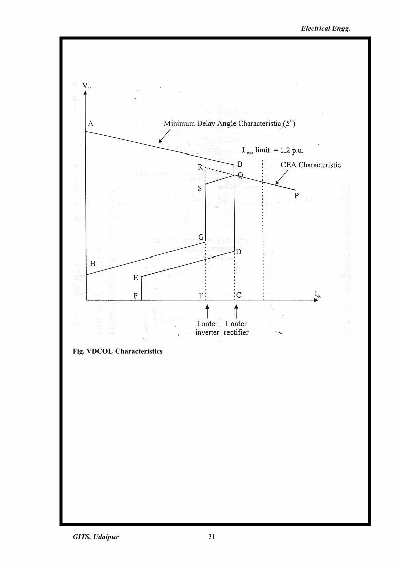
3.3.3 VOLTAGE DEPENDENT CURRENT ORDER LIMIT (VDCOL)Under low voltage conditions, it may not b? desirable-or possible to
maintain rated direct current or power for the following reasons:
(a) When voltage at one converter drops by more than 30%, the reactive
power demand of remote converter increases and this may have adverse
effect on AC system.
(b) At reduced voltages, there are also risks of commutation failure and
voltage instability.
These problems associated with operation under low voltage conditions
may be prevented by using "Voltage-dependent current -order limit"
(VDCOL). This limit reduces the maximum allowable direct current when the
voltage drops below a predetermined value. The rectifier inverter
characteristics, including VDCOL is shown in fig.3.4
GITS, Udaipur 26
Electrical Engg.
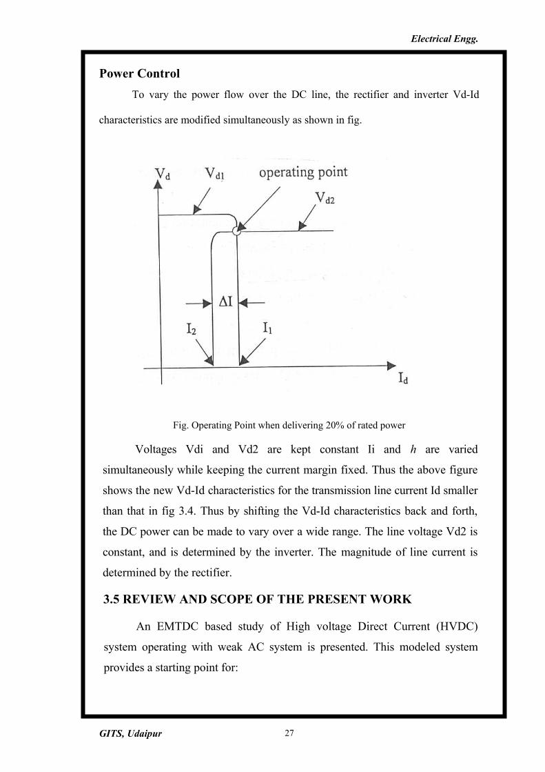
Power Control
To vary the power flow over the DC line, the rectifier and inverter Vd-Id
characteristics are modified simultaneously as shown in fig.
Fig. Operating Point when delivering 20% of rated power
Voltages Vdi and Vd2 are kept constant Ii and h are varied
simultaneously while keeping the current margin fixed. Thus the above figure
shows the new Vd-Id characteristics for the transmission line current Id smaller
than that in fig 3.4. Thus by shifting the Vd-Id characteristics back and forth,
the DC power can be made to vary over a wide range. The line voltage Vd2 is
constant, and is determined by the inverter. The magnitude of line current is
determined by the rectifier.
3.5 REVIEW AND SCOPE OF THE PRESENT WORK
An EMTDC based study of High voltage Direct Current (HVDC)
system operating with weak AC system is presented. This modeled system
provides a starting point for:
GITS, Udaipur 27
Electrical Engg.
Educators teaching HVDC transmission courses
For utility planners to develop their own low cost dedicated digital simulators for
training purposes.
Modeling details for the following subsystems are provided:
DC converters including representation of snubber circuits.
DC controls for rectifier and inverter
AC system including filters
DC system including filters.
GITS, Udaipur 28
Electrical Engg.
GITS, Udaipur 29
Electrical Engg.
GITS, Udaipur 30
Electrical Engg.
Fig. VDCOL Characteristics
GITS, Udaipur 31
Electrical Engg.
SIMULATION OF HVDC SYSTEMS [7]:
The planning, design and operation of HVDC systems requires the
detailed study of various options and prediction of system performance. The
system performance involves simulation in both steady state and transient
conditions.
Large and complex systems are usually described by non-linear models
and thus are not tractable for analytical approaches. Simulation is the only tool
for predicting accurately the system performance under various operating
conditions or when subjected to certain disturbances.
The simulation of HVDC system are aimed at determining the following
1. DC power transfer under various normal and contingency conditions.
2. Reactive power, requirements.
3. Over voltages at fundamental frequency
4. Post fault DC power recovery
5. Resonance problems
6. AC and DC filter design
7. Controller requirement's under normal and faulted system conditions.
4.1 DIGITAL DYNAMIC SIMULATION
Every utility can have a computer program, while only a few
establishments can have physical simulator. With the availability of
inexpensive micro or mini computers, it is possible to have dedicated
computers for DC simulation and the costs are considerably reduced. It is
possible to develop a digital simulator with most general model of a component
that is risible. The parameters of this model can be varied over a wide range.
GITS, Udaipur 32
Electrical Engg.
4.2ADVANTAGES OF DIGITAL SIMULATION
1. Easy transportability and maintenance
2. Reduced cost of simulation
3. Flexibility in terms of representing any component of the system
4.3PSCAD/EMTDC SIMULATION TOOL
PSCAD/EMTDC has been used in this project to perform the
modeling and analysis of HVDC systems. PSCAD/EMTDC is an industry
standard simulation tool for studying the transient behavior of electrical
networks. Its graphical user interface enables all aspects of the simulation
to be conducted within a single integrated environment including circuit
assembly, run-time control, analysis of results, and reporting.
4.4 MODELLING OF HVDC SYSTEMS
The HVDC system modeled is operating with weak AC system
having short circuit ratio of 2.6. A six-pulse converter system is utilized
here. It is thus necessary to add 5th , 7th 11th and 13* harmonic filters to
compensate1-for the harmonics generated by the converter.
4.4.1 POWER SYSTEM
The power system consists of AC side of the system, DC side of the
system and converter units.
The AC side of the HVDC system consists of an AC supply network,
AC filters and transformers on both the rectifier and inverter side.
AC SIDE OF THE SYSTEM
The AC side of the HVDC system consists of AC supply network, AC
filters and transformers on both rectifier and inverter side.
GITS, Udaipur 33
Electrical Engg.
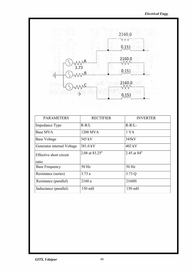
AC SUPPLY NETWORK
The AC supply network is represented by a Thevenin equivalent circuit
as shown in fig.4.1. The Thevenins equivalent voltage represents the source
voltage and the equivalent impedance represents the source impedance.
AC FILTERS
The AC filters are used to absorb the harmonics generated by the
converter. In addition, they are also used to provide reactive power required by
the converter unit. The AC fillers !.:clude filters for 5th, 7th, 11th and 13th-harmonics
as shown in fig 4.2
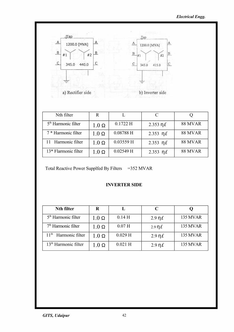
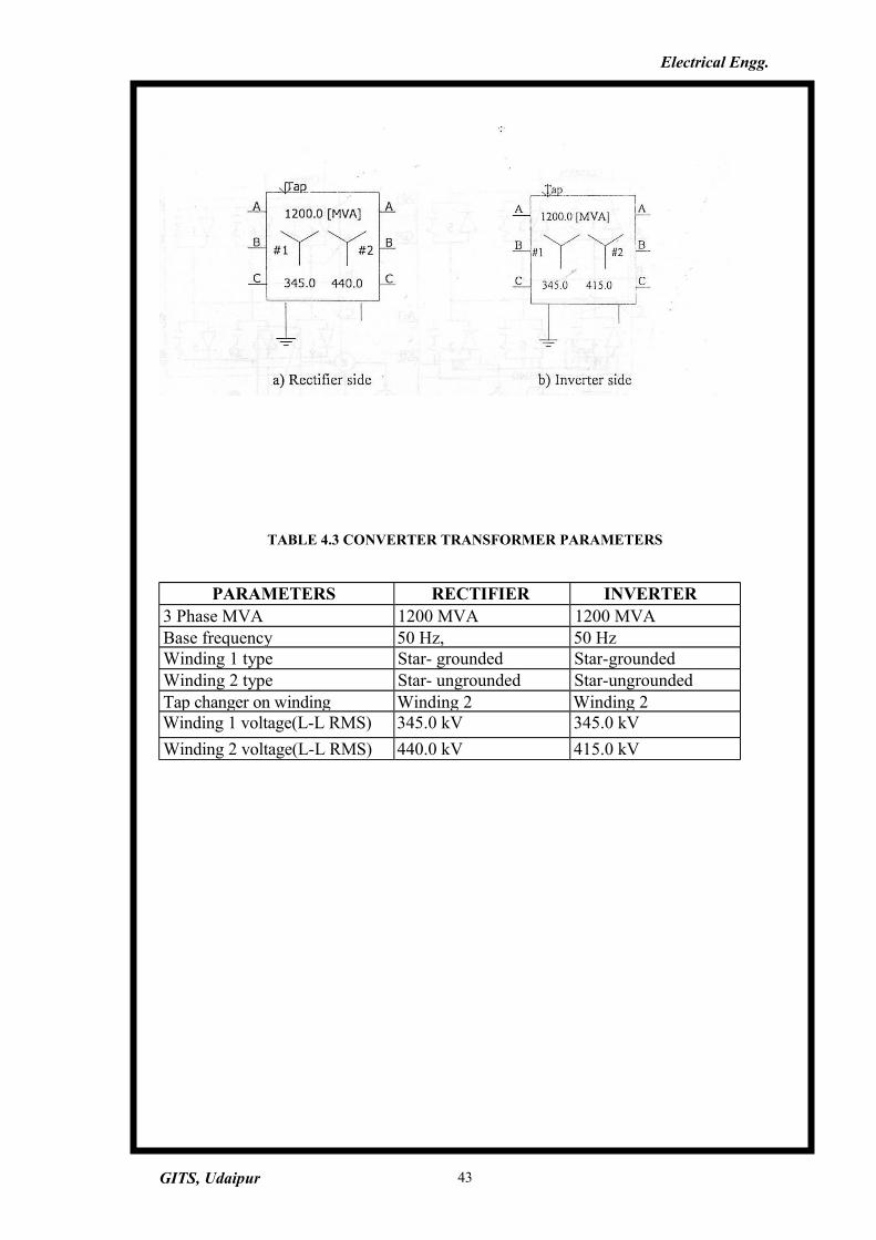
CONVERTER TRANSFORMERS:
The converter transformers are connected in star with neutral point
ungrounded on the valve side as shown in fig 4.3. On AC side the transformers
are connected in parallel with neutral grounded.
DC SIDE OF THE SYSTEM
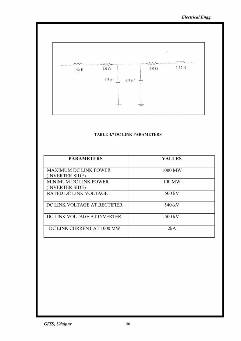
The DC side of the converter system consists of smoothing reactor for
the rectifier arid the inverter bridges. The DC transmission line is represented by
an equivalent T-network as shown in fig 4.4. The DC transmission line is tuned
close to the fundamental frequency providing a difficult resonant condition for
the modeled.
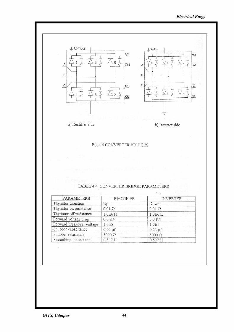
CONVERTER UNITS
In converter model shown in fig.4.5,' each of the 6 valves of the
converter is modeled as an ideal switch. Each valve model has a RC snubber
circuit placed in parallel with ideal switch for dv/dt protection. The RC snubber
circuit provides an alternative current flow path when the switch opens.
4.4.2 CONTROL SYSTEM
The control system consists of gate firing unit (GFU), rectifier control
system and inverter control system.
GITS, Udaipur 34
Electrical Engg.
The gate firing unit consists of synchronization and triggering systems
for rectifier side and inverter side.
The control system at rectifier side is a current controller. The control
system at inverter side is comprised of a current controller and a gamma
controller operating in parallel. At any particular moment only one of these
controllers will be in command while the other one was biased off with the aid
of a current margin signal.
GATE FIRING UNIT
Due to weak AC system, the commutation bus voltage has harmonics
present. The converter is connected to this bus, therefore requires a gate firing
unit (GFU) to provide gating signals to the converter valves which are
synchronised to the commutation voltage. In this project, to model HVDC
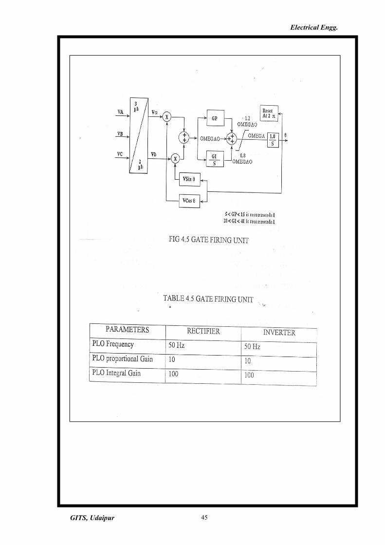
converter system a DQ type GFU is used. The GFU consists of phase locked
loop in conjunction with Voltage controlled oscillator. The block diagram of a
DQ-type GFU is shown in fig 4.6. The three phase commutation voltages Va,
Vb and Vc are transformed into DQ axis voltages Valpha and Vbeta using equations
2 and 3 respectively.
Valpha = 2/3 Va -1/3 Vb - 1/3 Vc ----------- (1)
Vbeta =l/V3(Vb-Vc) ---------- (2)
Error = -ValphaVsin + VbetaVcos -------------- (3)
An error signal is derived using equation (3). The error signal is fed to a
PI controller, which generates a reference value for VCO. This reference value
can be added to a fixed voltage bias Vref which sets the center frequency (50
Hz) of VCO.
Under steady state, this error is reduced to zero and the output of sine-
cosine oscillator will be in synchronism with the commutation voltage.
GITS, Udaipur 35
Electrical Engg.
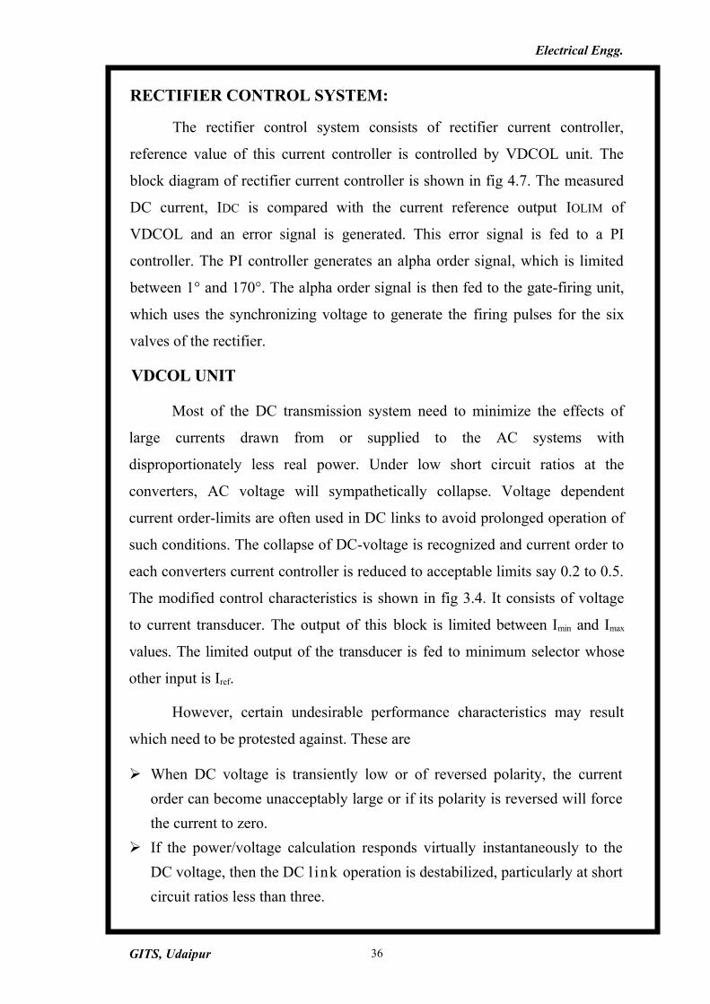
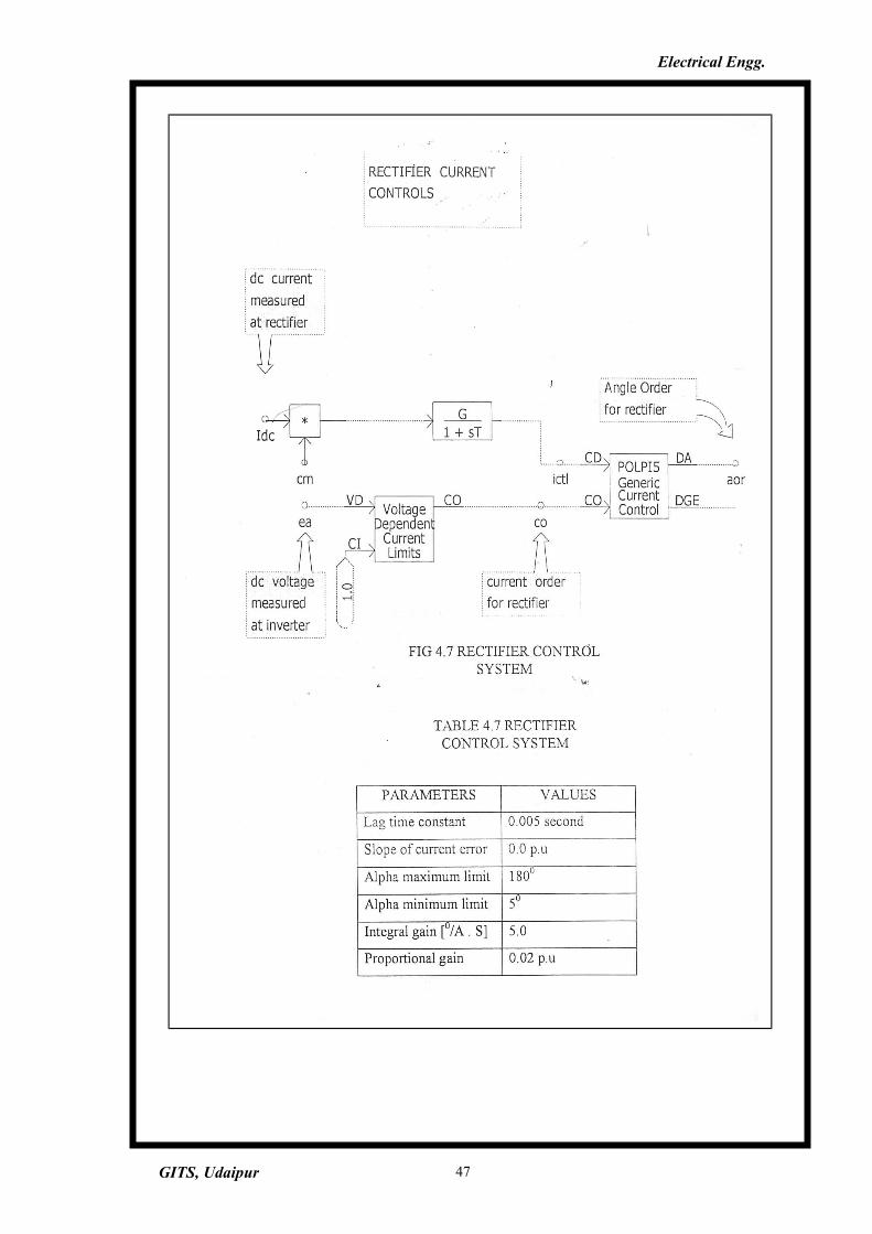
RECTIFIER CONTROL SYSTEM:
The rectifier control system consists of rectifier current controller,
reference value of this current controller is controlled by VDCOL unit. The
block diagram of rectifier current controller is shown in fig 4.7. The measured
DC current, IDC is compared with the current reference output IOLIM of
VDCOL and an error signal is generated. This error signal is fed to a PI
controller. The PI controller generates an alpha order signal, which is limited
between 1° and 170°. The alpha order signal is then fed to the gate-firing unit,
which uses the synchronizing voltage to generate the firing pulses for the six
valves of the rectifier.
VDCOL UNIT
Most of the DC transmission system need to minimize the effects of
large currents drawn from or supplied to the AC systems with
disproportionately less real power. Under low short circuit ratios at the
converters, AC voltage will sympathetically collapse. Voltage dependent
current order-limits are often used in DC links to avoid prolonged operation of
such conditions. The collapse of DC-voltage is recognized and current order to
each converters current controller is reduced to acceptable limits say 0.2 to 0.5.
The modified control characteristics is shown in fig 3.4. It consists of voltage
to current transducer. The output of this block is limited between Imin and Imax
values. The limited output of the transducer is fed to minimum selector whose
other input is Iref.
However, certain undesirable performance characteristics may result
which need to be protested against. These are
When DC voltage is transiently low or of reversed polarity, the current
order can become unacceptably large or if its polarity is reversed will force
the current to zero.
If the power/voltage calculation responds virtually instantaneously to the
DC voltage, then the DC l ink operation is destabilized, particularly at short
circuit ratios less than three.
GITS, Udaipur 36
Electrical Engg.
To overcome these two difficulties, a master power controller should
be constructed with limits and lag functions applied. In the figure 4.9, if T2 is
of small duration, the P/V divider responds quickly. Therefore T2 lag function
time constant cannot be too large, but in the order of 5 to 50 milliseconds to
represent the dynamic response of the P/V divider. Further if DC link
instability at low short circuit ratios is to be avoided, the Tl time constant in
the measured voltage signal must be large. For SCR less than two. Tl should
be greater than one or two seconds.
4.5 INFLUENCE OF AC SYSTEM STRENGTH [7]
The nature of AC/DC system interactions and associated problems are
very much dependent on the strength of AC system relative to the capacity of
the DC link. The AC system can be considered as weak from two aspects
AC system impedance may be high
AC system mechanical inertia may be low
SHORT CIRCUIT RATIO
Short circuit ratio is defined as
SCR - short rirr.int MVA of AC system DC converter MW rating
The short circuit MVA is given by
SC MVA = E2ac / Zth
Where Eac is the commutation bus voltage at rated DC power and Zy, is
the thevinin equivalent impedance of the AC system.
The basic SCR gives the inherent strength of the AC system. From the
view point of the HVDC system performance, it is more meaningful to
consider the effective short circuit ratio (ESCR), which includes the effects
GITS, Udaipur 37
Electrical Engg.
of AC side equipment associated with the DC link: filters, shunt capacitors,
synchronous condensers, etc.
The AC system strength has been classified as follows
High, if ESCR is greater than 5
Moderate, if ESCR is between 3 and 5
Low, if ESCR is less than 3
PROBLEMS WITH LOW ESCR SYSTEMSThe following are the problems associated with the operation of a DC system
when connected to a weak AC system.
High dynamic over voltages
Voltage instability
Harmonic resonance and
Objectionable voltage flicker
4.6 HARMONIC INSTABILITY (7) :
Harmonic instability is a phenomenon that occurs when AC and DC side
networks in an HVDC transmission system have impedance, which results in the
amplification of voltage or current at one particular frequency [1]. It has often been
assumed that harmonic instabilities arise if the AC and DC side networks are tuned to
complementary frequencies that is if the AC side has a resonance at a frequency fi and the
DC side is resonant at f2 where f-.-fo = ±fo. fo being the fundamental operating frequency
(50 Hz in our case). The reason given is that the converter transforms.
frequencies f on one side to frequencies f + of on the other. Thus if resonance s
on either side differ by of, the converter action would couple them and cause
instability.
4.7 FREQUENCY SCANNING TECHNIQUE [8]
GITS, Udaipur 38
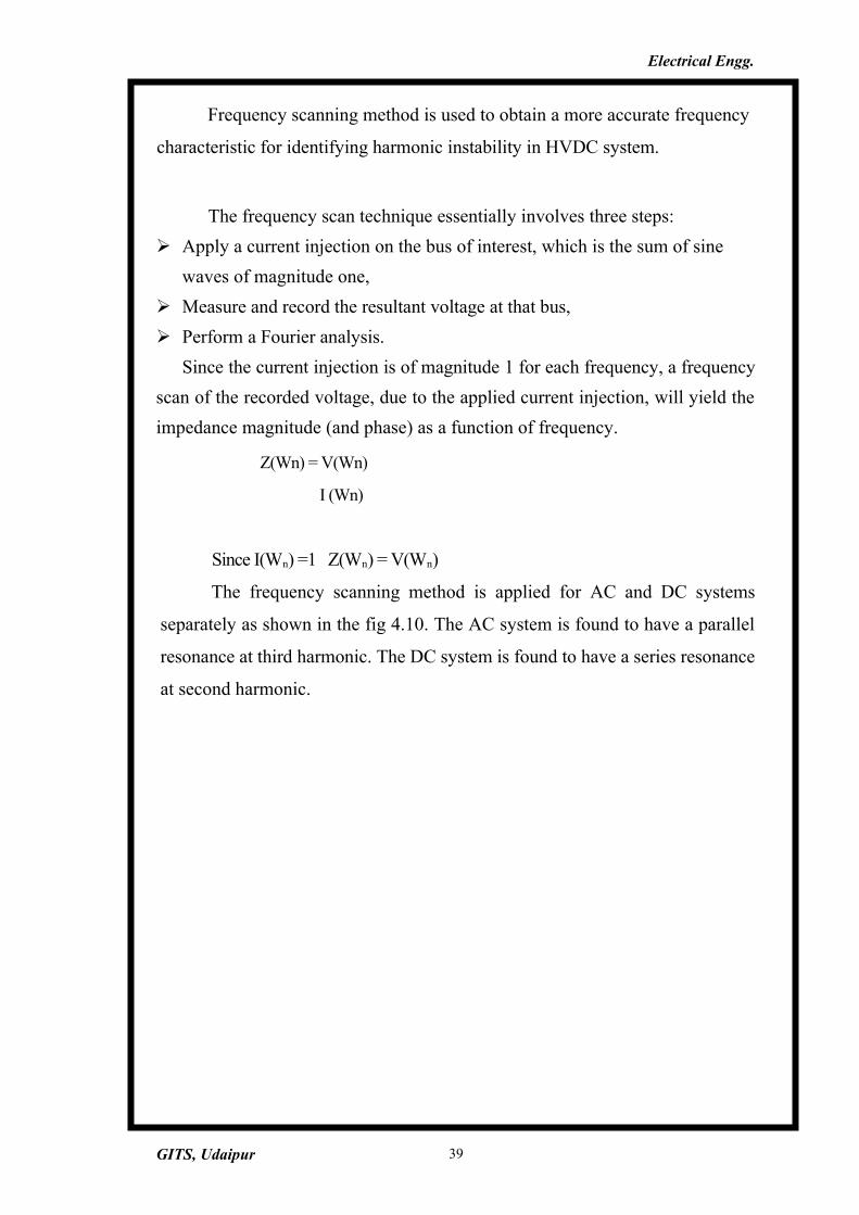
Electrical Engg.
Frequency scanning method is used to obtain a more accurate frequency
characteristic for identifying harmonic instability in HVDC system.
The frequency scan technique essentially involves three steps:
Apply a current injection on the bus of interest, which is the sum of sine
waves of magnitude one,
Measure and record the resultant voltage at that bus,
Perform a Fourier analysis.
Since the current injection is of magnitude 1 for each frequency, a frequency
scan of the recorded voltage, due to the applied current injection, will yield the
impedance magnitude (and phase) as a function of frequency.
Z(Wn) = V(Wn)
I (Wn)
Since I(Wn) =1 Z(Wn) = V(Wn)
The frequency scanning method is applied for AC and DC systems
separately as shown in the fig 4.10. The AC system is found to have a parallel
resonance at third harmonic. The DC system is found to have a series resonance
at second harmonic.
GITS, Udaipur 39
Electrical Engg.
PARAMETERS RECTIFIER INVERTER
Impedance Type R-R/L R-R/L-
Base MVA 1200 MVA 1 VA
Base Voltage 345 kV 345kV
Generator internal Voltage 381.0 kV 402 kV
Effective short circuit
ratio
2.08 at 83.250 2.45 at 840
Base Frequency 50 Hz 50 Hz
Resistance (series) 3.73 a 3.73 Q
Resistance (parallel) 2160 a 2160H
Inductance (parallel) 150 mH 150 mH
GITS, Udaipur 40
Electrical Engg.
GITS, Udaipur 41
Electrical Engg.
Fig. CONVERTER TRANSFORMER
Nth filter R L C Q
5th Harmonic filter 1.0 Ω 0.1722 H 2.353 η£ 88 MVAR
7 * Harmonic filter 1.0 Ω 0.08788 H 2.353 η£ 88 MVAR
11 Harmonic filter 1.0 Ω 0.03559 H 2.353 η£ 88 MVAR
13* Flarmonic filter 1.0 Ω 0.02549 H 2.353 η£ 88 MVAR
Total Reactive Power Supplfed By Filters =352 MVAR
INVERTER SIDE
Nth filter R L C Q
5th Harmonic filter 1.0 Ω 0.14 H 2.9 η£ 135 MVAR
7th Harmonic filter 1.0 Ω 0.07 H 2.9 η£ 135 MVAR
11th Harmonic filter 1.0 Ω 0.029 H 2.9 η£ 135 MVAR
13th Harmonic filter 1.0 Ω 0.021 H 2.9 η£ 135 MVAR
GITS, Udaipur 42
Electrical Engg.
TABLE 4.3 CONVERTER TRANSFORMER PARAMETERS
PARAMETERS RECTIFIER INVERTER3 Phase MVA 1200 MVA 1200 MVABase frequency 50 Hz, 50 HzWinding 1 type Star- grounded Star-groundedWinding 2 type Star- ungrounded Star-ungroundedTap changer on winding Winding 2 Winding 2Winding 1 voltage(L-L RMS) 345.0 kV 345.0 kV
Winding 2 voltage(L-L RMS) 440.0 kV 415.0 kV
GITS, Udaipur 43
Electrical Engg.
GITS, Udaipur 44
--
Electrical Engg.
GITS, Udaipur 45
Electrical Engg.
TABLE 4.7 DC LINK PARAMETERS
PARAMETERS VALUES
MAXIMUM DC LINK POWER (INVERTER SIDE)
1000 MW
MINIMUM DC LINK POWER (INVERTER SIDE)
100 MW
RATED DC LINK VOLTAGE 500 kV
DC LINK VOLTAGE AT RECTIFIER 540-kV
DC LINK VOLTAGE AT INVERTER 500 kV
DC LINK CURRENT AT 1000 MW 2kA
GITS, Udaipur 46
Electrical Engg.
GITS, Udaipur 47
Electrical Engg.
VDCOL PARAMETERS VALUES
Range of voltage between which
VDCOL is applied
0.7 pu to 0.3 pu
Lag time constant 0.02 seconds
Current limit 0.2 pu
Current order recovery rate 15 [pu/sec]
Voltage rating/group 500 KV
GITS, Udaipur 48
Electrical Engg.
CURRENT CONTROLLER GAMMA CONTROLLER
Current margin 0.15 pu Alpha minimum limit 18°
Alpha minimum limit 90° Minimum gamma order 180
Alpha maximum limit 180° Proportional gain 0.2 pu
Proportional gain 0.02 Integral gain (°/ A . s) 20.0
Integral gain (0/ A . s) 5.0
GITS, Udaipur 49
Electrical Engg.
GITS, Udaipur 50
Electrical Engg.
GITS, Udaipur 51
Electrical Engg.
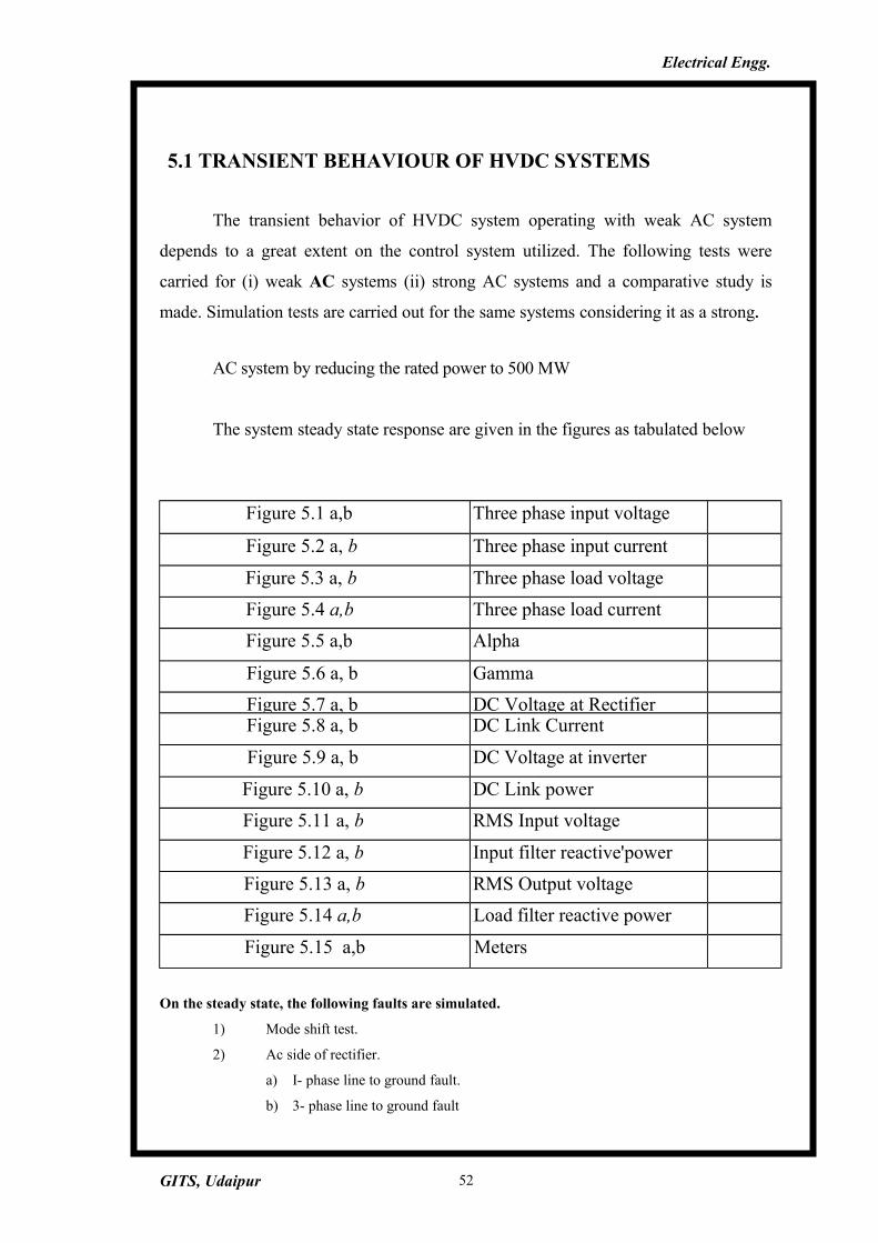
5.1 TRANSIENT BEHAVIOUR OF HVDC SYSTEMS
The transient behavior of HVDC system operating with weak AC system
depends to a great extent on the control system utilized. The following tests were
carried for (i) weak AC systems (ii) strong AC systems and a comparative study is
made. Simulation tests are carried out for the same systems considering it as a strong.
AC system by reducing the rated power to 500 MW
The system steady state response are given in the figures as tabulated below
Figure 5.1 a,b Three phase input voltage
Figure 5.2 a, b Three phase input current
Figure 5.3 a, b Three phase load voltage
Figure 5.4 a,b Three phase load current
Figure 5.5 a,b Alpha
Figure 5.6 a, b Gamma
Figure 5.7 a, b DC Voltage at RectifierFigure 5.8 a, b DC Link Current
Figure 5.9 a, b DC Voltage at inverter
Figure 5.10 a, b DC Link power
Figure 5.11 a, b RMS Input voltage
Figure 5.12 a, b Input filter reactive'power
Figure 5.13 a, b RMS Output voltage
Figure 5.14 a,b Load filter reactive power
Figure 5.15 a,b Meters
On the steady state, the following faults are simulated.
1) Mode shift test.
2) Ac side of rectifier.
a) I- phase line to ground fault.
b) 3- phase line to ground fault
GITS, Udaipur 52
Electrical Engg.
3) AC side of inverter.
a) I-phase line to ground fault
b) 3-phase line to ground fault.
4) DC Link fault
a) Rectifier side
b) Inverter side
The following time response waveforms for both weak and strong AC
systems are shown
1. Alpha
2. Gamma
3. DC voltage at rectifier
4. DC voltage at inverter
5. DC link current
6. DC link power
7. RMS input voltage
8. RMS output voltage
9. Input filter reactive power
10. Output filter reactive power
Mode Shift Test:
This test is a particularly interesting test to study the dynamics of the dc
system when the control mode is shifted from the rectifier current controller to
the inverter current.controller, £nd vice-versa. Initially the rectifier current
controller is in control at the rectifier, whilst the gamma controller is in control
at the inverter. At t=2s, the AC voltage at the rectifier end is reduced by 5%
which causes the rectifier to hit its alpha-min limit and lose control over the
DC system current. The inverter current controller which has been biased off
by its current margin of 10%, is forced to take over current control to its
GITS, Udaipur 53
Electrical Engg.
reference value of 0.9 pu. This transition is usually not a difficult one for the
DC system since the DC current is being reduced to 0.9 pu and the rectifier
current controller is being forced to its hard limit. At t=5s, the AC voltage at
the rectifier is returned to its nominal value of 1 pu, and the rectifier current
controller is forced off its alpha-min limit an takes charge of the DC current.
This transition is usually more difficult and dramatic since the current is being
increased, and the rectifier current controller is being forced to come off its hard limit
which normally requires more time. This transition can therefore result in a
communication failure at the inverter when dealing with vulnerable DC systems
operating with weak AC systems.
The waveforms for both weak and strong AC systems are presented in
the figures as below.
Figure 5.16 a, b Alpha
Figure 5.17 a, b Gamma
Figure 5.18 a, b DC Voltage at Rectifier
Figure 5.19 a, b DC Link Current
Figure 5.20 a, b DC Voltage at inverter
Figure 5.21 a, b DC Link power
Figure 5.22 a, b RMS Input voltage
Figure 5.23 a, b Input filter reactive power
Figure 5.24 a, b RMS Output voltage
Figure 5.25 a, b Load filter reactive power
From the simulation study results conducted in strong and weak AC
systems following conclusions are drawn. From figures 5.16 to 5.25 its clear that
1- The voltage flicker is more in weak AC systems.
2- The dynamic over voltages is high in weak AC systems when compared
to strong AC systems.
1 - Phase line to ground fault at inverter (fault time=0.1)
A commutation failure at the inverter is simulated by creating a single
-phase 1- cycle at the inverter AC bus at t=2s to 2.1s. The resulting
commutation failure causes the DC voltage to momentarily drop to zero. This
causes the sloped portion of the VDCOL to operate and limit the DC current to
IMIN. The recovery process is initiated almost immediately resulting in the
GITS, Udaipur 54
Electrical Engg.
DC current to ramp up according to the VDCOL. A transition from the
inverter current controller to the rectifier current controller is also observed.
Figure 5.36 a, b Alpha
Figure 5.37 a, b Gamma
Figure 5.38 a, b DC Voltage at Rectifier
Figure 5.39 a, b DC Link Current
Figure 5.40 a, b DC Voltage at inverter
Figure 5.41 a, b DC Link power
Figure 5.42 a, b RMS Input voltage
Figure 5.43 a, b Input filter reactive power
Figure 5.44 a, b RMS Output voltage
Figure 5.45 a, b Load filter reactive power
From the simulation study results conducted in strong and weak AC
systems following conclusions are drawn. From figures 5.36 to 5.45 its clear that
1 The voltage flicker is more in weak AC systems.
2 The dynamic over voltages are high in weak AC systems when compared
to strong AC systems.
3 - Phase ground fault at inverter (fault time = Is)
The response of the system under this fault is identical to the
response obtained during a single - phase fault . The only obvious difference
is seen at the inverter end DC voltage, where oscillations are present due to the
reflections on the DC transmission line.
The waveforms for both weak and strong AC systems are presented in
the figures as below.
Figure 5.46 a, b Alpha
Figure 5.47 a, b Gamma
Figure 5.48 a, b DC Voltage at Rectifier
Figure 5.49 a, b DC Link Current
Figure 5.50 a, b DC Voltage at inverter
Figure 5.51 a, b DC Link power
GITS, Udaipur 55
Electrical Engg.
Figure 5.52 a, b RMS Input voltage
Figure 5.53 a, b Input filter reactive power
Figure 5.54 a, b RMS Output voltage
Figure 5.55 a, b Load filter reactive power
From the simulation study results conducted in strong and weak AC
systems following conclusions are drawn. From figures 5.46 to 5.55 its clear that
1 The voltage flicker is more in weak AC systems.
2 The dynamic over voltages are high in weak AC systems when
compared to strong AC systems.
1 - Phase line to ground fault at rectifier (fault time =0.1 s)
A single - phase 5 cycle fault is applied at the rectifier AC bus. The DC
current during the fault from t=2s to 3s contains a second harmonic component
(100 Hz) which is characteristic of such a fault. The DC current then follows a
pattern similar to the single - phase one - cycle fault at the inverter.
The waveforms for both weak and strong AC systems are presented in the figures as below.
Figure 5.56 a, b Alpha
Figure 5.57 a, b Gamma
Figure 5.58 a, b DC Voltage at Rectifier
Figure 5.59 a, b DC Link Current
Figure 5.60 a, b DC Voltage at inverter
Figure 5.61 a, b DC Link power
Figure 5.62 a, b RMS Input voltage
Figure 5.63 a, b Input filter reactive power
Figure 5.64 a, b RMS Output voltage
Figure 5.65 a, b Load filter reactive power
From the simulation study results conducted in strong and weak AC systems following conclusions are drawn. From figures 5.56 to 5.65 its clear that.
GITS, Udaipur 56
Electrical Engg.
1 The voltage flicker is more in weak AC systems.
1 The dynamic over voltages are high in weak AC systems when compared
to strong AC systems.
3 - phase line to ground fault at rectifier (fault time = Is)
The fault.-causes the DC voltage to collapse and hence reduces the
DC current to zero due to the lack of a driving source voltage. The
behaviour of the VDCL drops IOLIM to IMIN, however, the absence of the
AC voltage at the rectifier prevents the current from recovering. Upon removal
of the AC fault at the rectifier bus, the DC voltage reaches 1.0 pu and the
current follows the same pattern as during initialization the case.
The waveforms for both weak and strong AC systems are presented in
the figures as below.
Figure 5.66 a, b Alpha
Figure 5.67 a, b Gamma
Figure 5.68 a, b DCVoltage at Rectifier
Figure 5.69 a, b DC Link Current
Figure 5.70 a, b DC Voltage at inverter
Figure 5.71 a, b DC Link power
Figure 5.72 a, b - RMS Input voltage
Figure 5.73 a, b Input filter reactive power
Figure 5.74 a, b RMS Output voltage
Figure 5.75 a, b
From the simulation study results conducted in strong and weak AC systems
following conclusions are drawn. From figures 5.66 to 5.75 its clear that
1 The voltage flicker is more in weak AC systems.
2 The dynamic over voltages are high in weak AC systems when compared to strong
AC systems
GITS, Udaipur 57
Electrical Engg.
DC line fault at the rectifier sideA DC line - fault is applied from 2.0s to 2.3s at the DC line side of the
rectifier. The fault causes the DC voltage to collapse and the DC current to
rise rapidly to a value greater than 2.0 pu, a characteristic of this type of fault.
The subsequent action of the VDCL causes the current to be limited to IMIN.
Upon removal of the fault, the DC current ramps up due to the action of the
VDCL. The small delay observed between Idc and IOLIM is due to use of a
low - pass filter in the VDCL limit.
The waveforms for both weak and strong AC systems are presented in
the figures as below.
Figure 5.76 a, b Alpha
Figure 5.77 a, b Gamma
Figure 5.78 a, b DC Voltage at Rectifier
. Figure 5.79 a, b DC Link Current
Figure 5.80 a, b DC Voltage at inverter
Figure 5.81 a, b DC Link power
Figure 5.82 a, b RMS Input voltage
Figure 5.83 a, b Input filter reactive power
Figure 5.84 a, b RMS Output voltage
From the simulation study 'results conducted in strong and weak AC
systems following conclusions are drawn. From figures 5.76 to 5.85 its clear
that-
1- The voltage ficker is more in weak AC system.
2- The dynamic over voltages are high in weak. AC systems when
compared to strong AC System.
DC Line fault at the inverter side.
GITS, Udaipur 58
Electrical Engg.
A DC fault is applied from 2.0s to 2.3s at the DC line side of the
inverter. The fault causes the DC voltage to collapse and the DC current
to rise to a value greater than 2.0 pu. Since the current in the inverter side
is shorted out of the DC line fault, hence during the fault duration the DC
current at the inverter end is zero.
The subsequent action of the VDCL causes the current to be limited to IMIN.
Upon removal of the fault, the DC current ramps up due to the action of the
sloping portion of the VDCL. The small delay observed between Idc and
IOLIM is due to the use of a low - pass filter in the VDCL unit.
The waveforms for both weak and strong AC systems are presented in
the figures as below.
Figure 5.86 a, b Alpha
Figure 5.87 a, b Gamma
Figure 5.88 a, b DC Voltage at Rectifier
Figure 5.89 a, b DC Link Current
Figure 5.90 a, b DC Voltage at inverter
Figure 5.91 a, b DC Link power
Figure 5.92 a, b RMS Input voltage
Figure 5.93 a, b Input filter reactive power
Figure 5.94 a, b RMS Output voltage
Figure 5.95 a, b Load filter reactive power
From the simulation study results conducted in strong and weak AC systems
following conclusions are drawn. From figures 5.86 to 5.95 its clear that
1 The voltage flicker is more in weak AC systems-.-
2 The dynamic over voltages are high in weak AC systems when
compared to strong AC systems.
GITS, Udaipur 59
Electrical Engg.
6.1 INTRODUCTION
The Rihand-Delhi HVDC Transmission Line, the first one in the country,
linking Rihand in UP. to Dadri, with two-converter stations at both ends to handle 1500
MW of power for conversion from 400 KV AC. to ± 500 KV D.C. and vice-versa,
with a considerable reduction in transmission loses. The project also includes two
electrode stations, one at Chapki, about 22 km from Rihand and the other at Dhankaur,
about 25 km from Dadri.
Biographical information of Dadri
Latitude N 28° 35' Longitude E 077° 36'
6.2 DESCRIPTION OF THE HVDC TERMINAL
Valve Hall
The valve hall houses the thyristor valves, which operate in the inverter
mode. The thyristor valves are air-insulated and cooled with dc-mineralized
water. Mechanically the valves are built up as quadruple valve units; i.e. each
physical structure contains four valve functions. For each pole, three quadruple
valves form a 12- pulse group. The quadruple valves are suspended from the
ceiling. Each single valve contains 96 series connected thyristor, three of
which are redundant. Each thyristor has a power handling capacity of 1.1 MYA.
One quadruple valve consists of 384 series-connected thyristors.
A thypistor or valve module is that part of a valve in a mechanical
assembly of series connected thyristors and their immediate auxiliaries
including heat sinks cooled by water in this case; damping circuits and valve
GITS, Udaipur 60
Electrical Engg.
firing electronics A thyristor module is usually interchangeable for
maintenance purposes and consists of electric components. The current rating
of the thyristors are of the magnitudes of the line current required for
transmission. However, the individual thyristor voltage capability is very small
as compared to the line voltage Therefore, a large number of thyristors have to
be connected in series to give the proper voltage rating. Thus a thyristor valve
is connected by a large number of thyristors connected in series. The valves are
of indoor design in the present case and are water-cooled. Since, the thyristor
may fail to an internal short circuit, the thyristor valve is equipped with a
number id extra (redundant) thyristors in series so that even if some of the
thyristors fail, the valve operation is not affected. The valves as already
mentioned have a modular design with each module having its associated heat
sink, control pulse generating circuits and voltage dividing circuits The purpose
of the voltage dividing circuit is to ensure a uniform voltage distribution along
a chain of thyristors when the valve is not conducting. The scheme uses a 12-
pulse converter. In a 12-pulse converter there are 12 pulsations (cycles of
ripple) of direct voltage per cycle of alternating equipment.
The Converter Transformers:
They are of the single-phase, three-winding type. The ungrounded-Y
valve winding bushings protrude inside the valve hall, while the delta valve-
side bushings are out- side. The salient features are; Single-Phase. 3 winding.
Quantity: 12-2 spare. Total weight 358 tones. The star winding bushings
protrude directly into the valve hall. The delta connections, which have a lower
GITS, Udaipur 61
Electrical Engg.
DC voltage, are made outside the valve hall The converter transformer
transforms the ac voltage to a suitable value for feeding the converter In
addition it serves the following functions:
• Reactive power is supplied to the converter through tap changing.
• Short circuit currents are controlled by suitable impedance values of
these transformers.
• The reactance of the converter transformer helps in harmonic
suppression.
• By suitable star-star and star-delta connections the required 30-degree
phase shift for the 12-pulse operation is achieved.
Smoothing reactors:
Two smoothing reactors are installed per pole. One oil-insulated of 360
mH and one air-insulated of 180 mH. The valve-side bushing of the oil-
insulated smoothing reactor protrudes directly into the valve hall. It serves the
following purposes:
• It prevents consequent commutation failures in the inverter by limiting the
rate of increase of direct current during commutation in one bridge when
the direct voltage of another bridge collapses.
• It decreases the incidence of commutation failures in the inverter during dips
in the alternating voltage.
• It decreases the harmonic voltages and currents in the dc line.
• It smoothens the ripple in the direct current sufficiently to prevent the
current from becoming discontinuous at light loads.
GITS, Udaipur 62
Electrical Engg.
• It limits the current on the rectifier when a short circuit occurs on lines
Two D.C Filters:
Two DC filters are installed in each pole, one double-tuned to the 12th and
24th harmonics, the other single-tuned to the 12th harmonic. The HVDC
transmission link can be operated without DC filters. However, the drawback is
the higher telephone interference associated with it. Characteristic D.C. side
voltage harmonics generated by a 6-pulse converter are of the order 6n and when
generated by a 12-pulse converter, are of the order 12n. D.C. side filters reduce
harmonic current flow on D.C. transmission lines to minimize coupling and
interference to adjacent voice frequency communication circuits. Where there
is no D.C. line such as in the back-to-back configuration, D.C. side filters may
not be required.
The AC filter banks:
To meet the filtering requirements and to control the interchange of
reactive power with the 400 kV network, three AC filter banks, each rated at
230 MVAR are installed in each station. Each AC filter bank consists of two
branches double-tuned to the 11th and 13th harmonics. One double- tuned to
the 3rd and 36th harmonics and one double-tuned to the 5th and 27th
harmonics. The characteristic a.c. side current harmonics generated by 6 pulse
converters are 6n ± 1 and 12n i 1 for 12 pulse converters, where n equals all
positive integers. A.C. filters are typically tuned to 11th, 13th, 23rd and 25 ,h
harmonics for 12 pulse converters.
The control and protection equipment:
GITS, Udaipur 63
Electrical Engg.
The control and protection equipment is of modem microprocessor-based
design with a high degree of redundancy. This allows the control and protection
systems to be serviced and maintained without disturbing the operation of the
system. The control of firing angle is very important in HVDC systems.
Electrical impulses, for firing have to be sent simultaneously to all thyristors
connected in series. The system adopted in most of the modem HVDC systems
and also in Rihand -Dadri HVDC system, uses light pulses, conducted through
fiber optic light guides. At each thyristor level, a light pulse is converted by
electronic circuits to an electric pulse, which is sent to thyristor gate.
Earth Electrode:
The project includes two electrode stations one at Chapki, about 22 km
from Rihand and the other at Dhankaur, about 25 Km from Dadri. The reasons
for situating the earth electrode at a safe distance from the terminal station is to
protect the pipelines (of gas power plant) and other apparatus in contact or
buried in soil from damage. The terminal station is connected to the earth
electrode through an insulated cable known as earth electrode line.
The following points are kept in mind while designing the earth station: -
Material of Earth Electrode: The electrolytic corrosion of anode is an
important consideration in selection of material and design of earth electrode.
Iron is not used due to its high rate of corrosion. Graphite has a somewhat lower
rate of corrosion but its direct burial in the earth also causes significant loss of
material due to corrosion. Instead graphite electrodes buried in a pit filled with
crushed coke are used.
GITS, Udaipur 64
Electrical Engg.
Design of earth electrode: The design aspects include the current density at
electrode surface, which should generally not exceed 1.5 A/m; the temperature
rise of electrodes and surroundings should be limited to 60 degree centigrade.
Shape of earth electrode: It may be a straight electrode, a ring electrode or a
radial star electrode.
6.3 CONTROL PRINCIPLES
The basic control concept for the Rihand- Delhi HVDC transmission is
based on pole current control performed by the rectifier through a feedback
control system and on pole- voltage control performed by the inverter through
minimum commutation margin and tap changer control. The inverter is
provided with a similar current control system as the rectifier to secure power
transmission under conditions of reduced sending end ac voltage. The current
order at the converter is however lower than that of the rectifier by an amount
known as the current margin, in order to prevent conflicts between the two
controllers. The basic control concept also includes tap changer control on all
converter transformers in both ends of the HVDC transmission. Since the
inverter is normally operating against its voltage limit (constant commutation
margin control), it will be possible to use its tap changers to keep the direct
voltage constant within desired limits. The tap changer controller at the rectifier
maintains the rectifier -firing angle within the range 12.5° to 17.5°
Thus the basic control concept provides a constant voltage system with
current control. When current control is transferred to the inverter for example
as a result of reducing sending end voltage, the tap changer action on the
GITS, Udaipur 65
Electrical Engg.
inverter side must be stopped. The reason being the inverter voltage ceiling no
longer determines the pole voltage. Without being able to intervene, the tap
changer would reach its end position and achieve nothing but a worsening of
the power factor.
6.4 PROTECTION SCHEMES
FOR D.C. SIDE
The D.C. side of the protection includes two categories of protection.
These are D.C. side protections detecting faults on the D.C. side of the
converter transformer. The other is beii\g the D.C. apparatus protection detecting
internal equipment faults.
Block A Protection
Commutation Failure Protection
The protection zone is 12-pulse converter and the objective is to detect the
jommutation failure within the protective zone and if the fault is persistent the
converter will be taken out of service. The commutation failures are detected on
a 6-pulse bridge basis. At commutation failures there are intervals, where all ac
phase currents are zero while a D.C. is still flowing two opposite valves in the
bridge, and so these intervals are detected
D.C. over voltage protection
The protective zone is all the equipment exposed to the d.c. lie voltage.
It detects the over voltages on the D.C. line. In such faults the steady state over
voltage will be limited to 1.15 p.u. by the over voltage limiter in the pole
control equipment. At the same time the D.C. on the D.C over voltage
protection will be very low due to open circuit. This is the basis for the
detection.
GITS, Udaipur 66
Electrical Engg.
D.C. line protection
The protective zone is the D.C line. The primary objective is to detect the
ground faults on the D.C. line .A ground fault on the D.C. line is characterized
by the fact that the direct voltage collapses to a low level at a certain
comparatively high rate. The protection utilizes the level and the derivative
criterion to detect a ground fault on the de line. This is the detection principle
employed for the D.C. line protection.
Block B Protection
D.C. harmonic protection
The protective zone .is the converter and the objective's to detect the
abnormal harmonics in the converter current. Such harmonics are generated at
valve disturbances. A.C. network disturbances and control equipment
malfunctioning.
Pole D.C. differential protection
The protective zone is the D.C side of the converter pole including the
D.C. filters The primary objective is to detect the ground faults within the
protective zone and take the faulty converter pole out of service.
D.C. minimum voltage protection
Protective zone is the DC line and all equipment connected to the DC.
line and thyristor valves. The primary objective is to detect the ground faults on
the dc line thus seeing as a backup fort the D.C. line protection and to protect the
thyristor valves from getting overloaded during low voltage conditions In case
the voltage dependent current order limit is malfunctioning.
Reverse power protection
GITS, Udaipur 67
Electrical Engg.
Protective zones are the Rihand and Singrauli generators. The primary
objective is to detect the power reversals due to control system failures. The
protection measured the DC current and the D.C. Voltage and calculated the
transmitted power if the calculated power is on direction from Delhi to Rihand
the protection will take the pole out of operation.
Excessive Delay angle protection
Protective zone is the damping circuit in the thyristor valves and primary
objective is to protect the resistors in the valve damping circuits against
overload during operations at too large firing and extinction angles. The
protection will also detect large delay angle operation due to faults in the tap
changers control equipment or faults in the converter firing control system.
For A.C. Side
Bus protection
For the bus differential protection there are two blocks, which are
electrically and physically separated. Block 1 consists of Check zone
differential protection A and B and the breaker failure protection. Block 2 of the
protection scheme consists of the bus differential protections A and B.
Bus bar protection
Bus bar differential protection: A high-speed differential relay RADSS is
used. RADSS is static, high-speed differential relays and a percentage restraint
differential relay in operating characteristic. The protective zone is one bus bar
per protection. The primary objective is to detect the phase-to-phase and ground
faults within the zone and isolate the faulty bus.
GITS, Udaipur 68
Electrical Engg.
6.5 OPERATIONAL PERFORMANCE
A few of the operational problems as mentioned below which affected
the performance of the link are as given below. However after thorough study,
necessary suggestions has been provided to ensure better performance of the
system.
Frequent operation of on load tap changer and switching of Filter bank:
In the Northern Region, voltage variations of the 400kV system of the
order of 50-60 KV were common in a day. Wide voltage variations resulted in
excessive operation of OLTC and filter circuit breakers. The setting of RPC
(Reactive Power Control) was changed to ± 18 kV from the original setting of
± 10 kV as a result of which the filter breaker and OLTC operation was
drastically reduced.
Failure Of Cotter Bolts On HVDC Line:
A series of mechanical failures of tension fitting due to shearing of
cotter bolts mounted on the anchor plate for the Quadruple Tension (OT) fitting
resulted in dropping of the conductor to the ground The hole provided in the
anchor plate for the cotter bolt is approximately 40 mm diameter, where as the
cotter bolt is 30mm diameter. The oversize hole of the anchor plate allowed
considerable movement of the cotter bolt resulting in wear and subsequent
stress failure. A bush made of hot dip galvanized forged (mild) steel or
electrically resistance welded high-pressure pipe was inserted in the anchor
plate to match the size of cotter bolt. Execution of work involved changing 1312
GITS, Udaipur 69
Electrical Engg.
bolts at 328 locations was completed in 24 days without lowering conductors or
fittings to the ground under induced volt condition with mono-polar operation
Flashover in de switchyard at Dadri converter station:
After energisation, Dadri HVDC terminal faced severe flash over in the
D.C. yard on 500kv insulators during intermittent light rain condition as well as
foggy whether condition. Even cleaning by high pressure or hand wiping did not
prevent flashover. However it was found that there has been almost a 100%
success with regard to the elimination of flashover with the application of
silicon grease is that must be applied every year. Lastly, it can be concluded that
the Rihand-Dadri HVDC link plays a major role in the stability of the northern
grid of India and has established a very high standard of availability and
reliability.
6.6 TRANSFER BETWEEN METALLIC AND GROUND RETURN
6.6.1 Transfer to Metallic return
To avoid high continuous currents through the ground when one pole in a
bipolar scheme is out of service, the remaining pole may use the non-energized
pole line conductor as return path (metallic return). The transfer between
ground and metallic return is normally done during operation. The figure below
shows the configuration at transfer from ground return to metallic return. The
figures on the switches show the recommended switching sequence.
GITS, Udaipur 70
Electrical Engg.
6.6.2 Transfer to Ground Return
The figure below shows the configuration at transfer from metallic return
to ground return. The figures on the switches show the recommended switching
sequence.
GITS, Udaipur 71