© Siemens AG 2010. All Rights Reserved.
Zone Selective Interlocking (ZSI) Functionality and Structure of ZSI For short circuit and ground fault as well Application Guide
© Siemens AG 2010. All Rights Reserved. Industry Sector Page 2
Selective tripping?
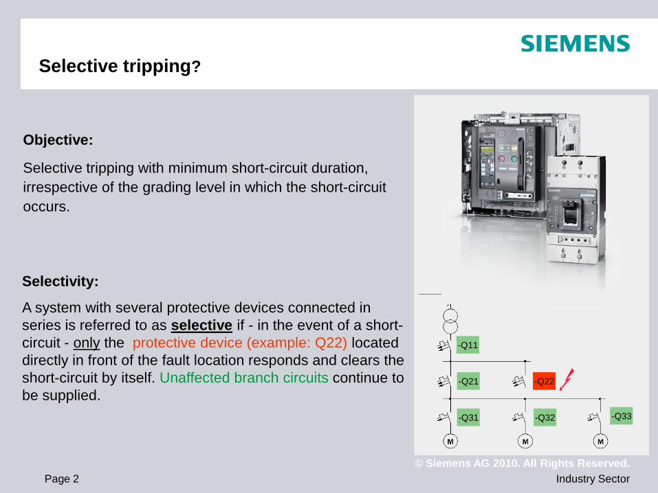
Objective:
Selective tripping with minimum short-circuit duration, irrespective of the grading level in which the short-circuit occurs.
Selectivity:
A system with several protective devices connected in series is referred to as selective if - in the event of a short-circuit - only the protective device (example: Q22) located directly in front of the fault location responds and clears the short-circuit by itself. Unaffected branch circuits continue to be supplied.
-Q11
-Q21
-Q33 -Q31 -Q32
-Q22
© Siemens AG 2010. All Rights Reserved. Industry Sector Page 3
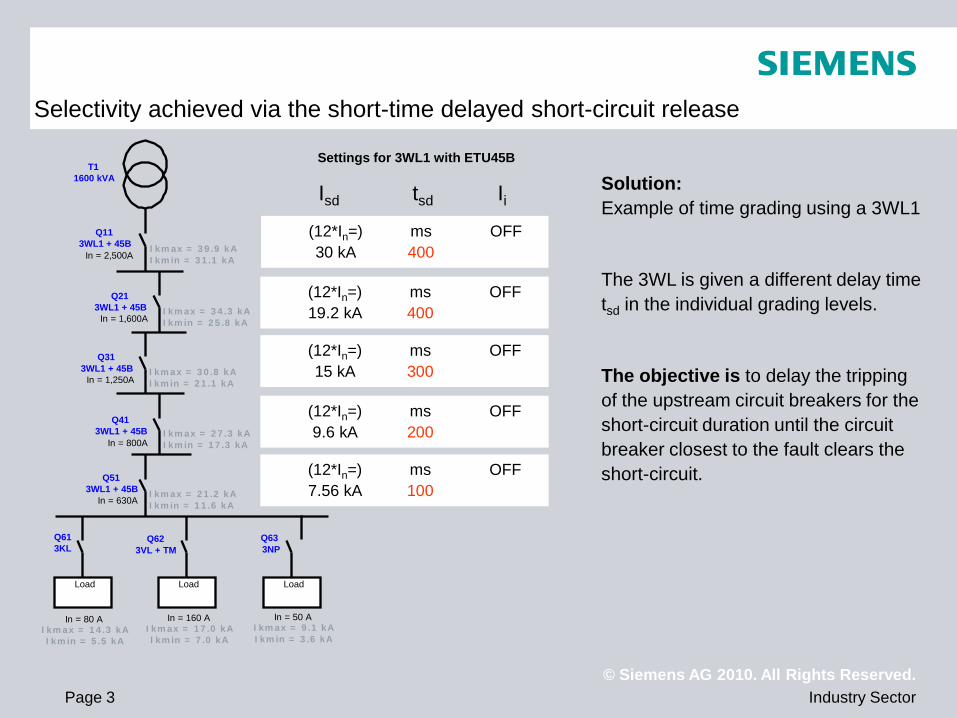
Isd tsd Ii (12*In=) ms OFF 30 kA 400
(12*In=) ms OFF 19.2 kA 400
(12*In=) ms OFF 15 kA 300
(12*In=) ms OFF 9.6 kA 200
(12*In=) ms OFF 7.56 kA 100
Solution: Example of time grading using a 3WL1
The 3WL is given a different delay time tsd in the individual grading levels.
The objective is to delay the tripping of the upstream circuit breakers for the short-circuit duration until the circuit breaker closest to the fault clears the short-circuit.
Load Load Load
Q11 3WL1 + 45B
Q21 3WL1 + 45B
Q31 3WL1 + 45B
Q41 3WL1 + 45B
Q51 3WL1 + 45B
Q61 3KL
Q62 3VL + TM
Q63 3NP
In = 80 A
T1 1600 kVA
In = 2,500A
In = 1,600A
In = 1,250A
In = 800A
In = 630A
In = 50 A In = 160 A Ikmax = 14.3 kA Ikmin = 5.5 kA
Ikmax = 39.9 kA Ikmin = 31.1 kA
Ikmax = 9.1 kA Ikmin = 3.6 kA
Ikmax = 17.0 kA Ikmin = 7.0 kA
Ikmax = 34.3 kA Ikmin = 25.8 kA
Ikmax = 30.8 kA Ikmin = 21.1 kA
Ikmax = 27.3 kA Ikmin = 17.3 kA
Ikmax = 21.2 kA Ikmin = 11.6 kA
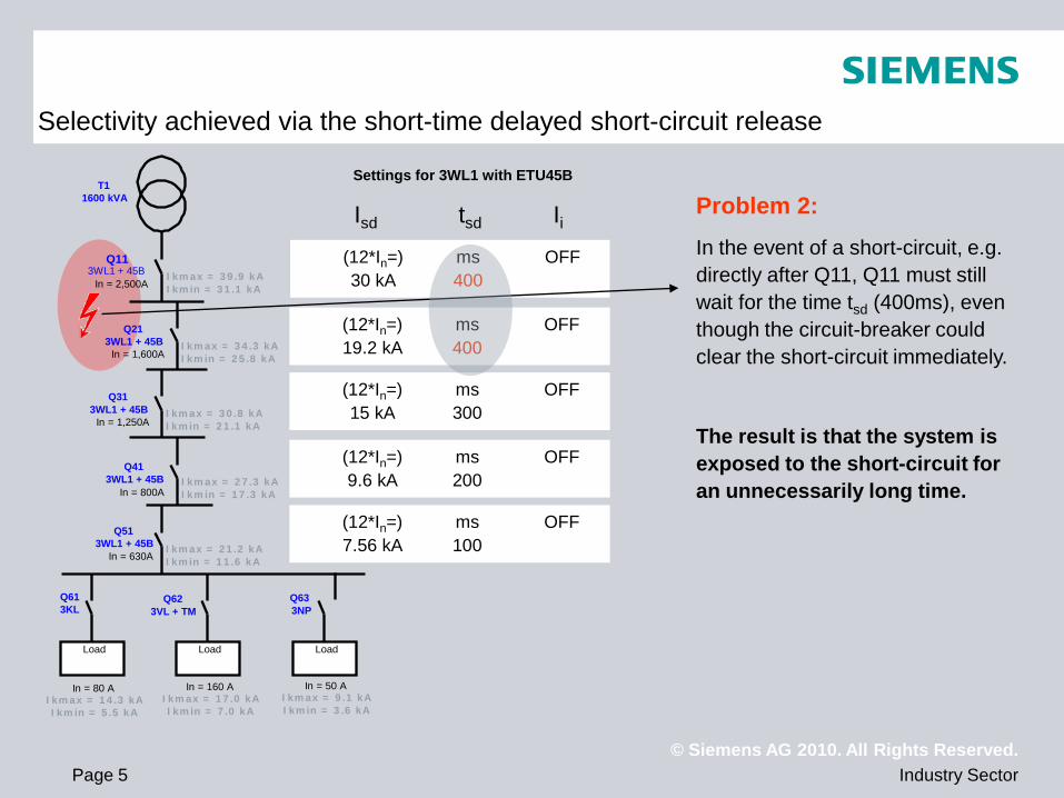
Selectivity achieved via the short-time delayed short-circuit release
Settings for 3WL1 with ETU45B
© Siemens AG 2010. All Rights Reserved. Industry Sector Page 4
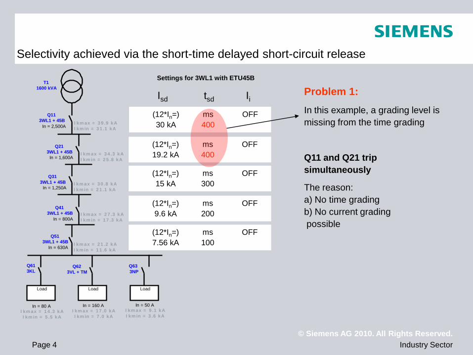
Isd tsd Ii (12*In=) ms OFF 30 kA 400
(12*In=) ms OFF 19.2 kA 400
(12*In=) ms OFF 15 kA 300
(12*In=) ms OFF 9.6 kA 200
(12*In=) ms OFF 7.56 kA 100
Problem 1: In this example, a grading level is missing from the time grading
Q11 and Q21 trip simultaneously
The reason: a) No time grading b) No current grading possible
Load Load Load
Q11 3WL1 + 45B
Q21 3WL1 + 45B
Q31 3WL1 + 45B
Q41 3WL1 + 45B
Q51 3WL1 + 45B
Q61 3KL
Q62 3VL + TM
Q63 3NP
In = 80 A
T1 1600 kVA
In = 2,500A
In = 1,600A
In = 1,250A
In = 800A
In = 630A
In = 50 A In = 160 A Ikmax = 14.3 kA Ikmin = 5.5 kA
Ikmax = 39.9 kA Ikmin = 31.1 kA
Ikmax = 9.1 kA Ikmin = 3.6 kA
Ikmax = 17.0 kA Ikmin = 7.0 kA
Ikmax = 34.3 kA Ikmin = 25.8 kA
Ikmax = 30.8 kA Ikmin = 21.1 kA
Ikmax = 27.3 kA Ikmin = 17.3 kA
Ikmax = 21.2 kA Ikmin = 11.6 kA
Selectivity achieved via the short-time delayed short-circuit release
Settings for 3WL1 with ETU45B
© Siemens AG 2010. All Rights Reserved. Industry Sector Page 5
Isd tsd Ii (12*In=) ms OFF 30 kA 400
(12*In=) ms OFF 19.2 kA 400
(12*In=) ms OFF 15 kA 300
(12*In=) ms OFF 9.6 kA 200
(12*In=) ms OFF 7.56 kA 100
Problem 2: In the event of a short-circuit, e.g. directly after Q11, Q11 must still wait for the time tsd (400ms), even though the circuit-breaker could clear the short-circuit immediately.
The result is that the system is exposed to the short-circuit for an unnecessarily long time.
Load Load Load
Q11 3WL1 + 45B
Q21 3WL1 + 45B
Q31 3WL1 + 45B
Q41 3WL1 + 45B
Q51 3WL1 + 45B
Q61 3KL
Q62 3VL + TM
Q63 3NP
In = 80 A
T1 1600 kVA
In = 2,500A
In = 1,600A
In = 1,250A
In = 800A
In = 630A
In = 50 A In = 160 A Ikmax = 14.3 kA Ikmin = 5.5 kA
Ikmax = 39.9 kA Ikmin = 31.1 kA
Ikmax = 9.1 kA Ikmin = 3.6 kA
Ikmax = 17.0 kA Ikmin = 7.0 kA
Ikmax = 34.3 kA Ikmin = 25.8 kA
Ikmax = 30.8 kA Ikmin = 21.1 kA
Ikmax = 27.3 kA Ikmin = 17.3 kA
Ikmax = 21.2 kA Ikmin = 11.6 kA
Selectivity achieved via the short-time delayed short-circuit release
Settings for 3WL1 with ETU45B
© Siemens AG 2010. All Rights Reserved. Industry Sector Page 6
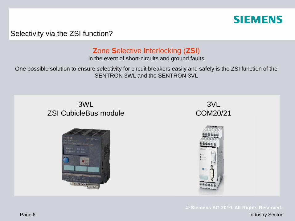
Selectivity via the ZSI function?
Zone Selective Interlocking (ZSI) in the event of short-circuits and ground faults
One possible solution to ensure selectivity for circuit breakers easily and safely is the ZSI function of the SENTRON 3WL and the SENTRON 3VL
3WL ZSI CubicleBus module
3VL COM20/21
© Siemens AG 2010. All Rights Reserved. Industry Sector Page 7
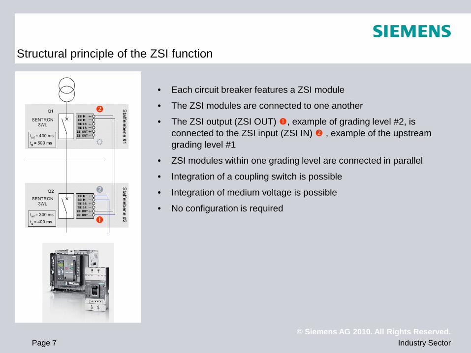
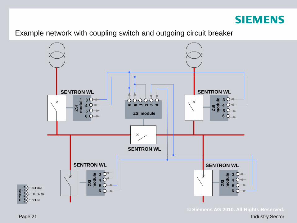
Structural principle of the ZSI function
• Each circuit breaker features a ZSI module
• The ZSI modules are connected to one another
• The ZSI output (ZSI OUT) , example of grading level #2, is connected to the ZSI input (ZSI IN) , example of the upstream grading level #1
• ZSI modules within one grading level are connected in parallel
• Integration of a coupling switch is possible
• Integration of medium voltage is possible
• No configuration is required
© Siemens AG 2010. All Rights Reserved. Industry Sector Page 8
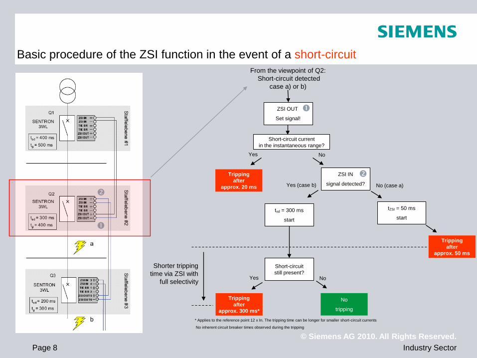
Basic procedure of the ZSI function in the event of a short-circuit
* Applies to the reference point 12 x In. The tripping time can be longer for smaller short-circuit currents
No inherent circuit breaker times observed during the tripping
ZSI OUT
Set signal!
From the viewpoint of Q2: Short-circuit detected
case a) or b)
Short-circuit current in the instantaneous range?
ZSI IN
signal detected?
Tripping after
approx. 20 ms
tZSI = 50 ms
start
Tripping after
approx. 50 ms
No
tripping
tsd = 300 ms
start
Short-circuit still present?
Tripping after
approx. 300 ms*
Shorter tripping time via ZSI with
full selectivity
Yes No
Yes (case b) No (case a)
Yes No
© Siemens AG 2010. All Rights Reserved. Industry Sector Page 9
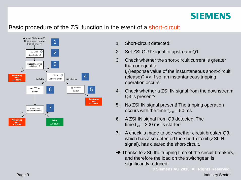
1. Short-circuit detected!
2. Set ZSI OUT signal to upstream Q1
3. Check whether the short-circuit current is greater than or equal to Ii (response value of the instantaneous short-circuit release)? => If so, an instantaneous tripping operation occurs
4. Check whether a ZSI IN signal from the downstream Q3 is present?
5. No ZSI IN signal present! The tripping operation occurs with the time tZSI = 50 ms
6. A ZSI IN signal from Q3 detected. The time tsd = 300 ms is started
7. A check is made to see whether circuit breaker Q3, which has also detected the short-circuit (ZSI IN signal), has cleared the short-circuit.
Thanks to ZSI, the tripping time of the circuit breakers, and therefore the load on the switchgear, is significantly reduced!
1
2
3
4
6 5
7
Basic procedure of the ZSI function in the event of a short-circuit
© Siemens AG 2010. All Rights Reserved. Industry Sector Page 10
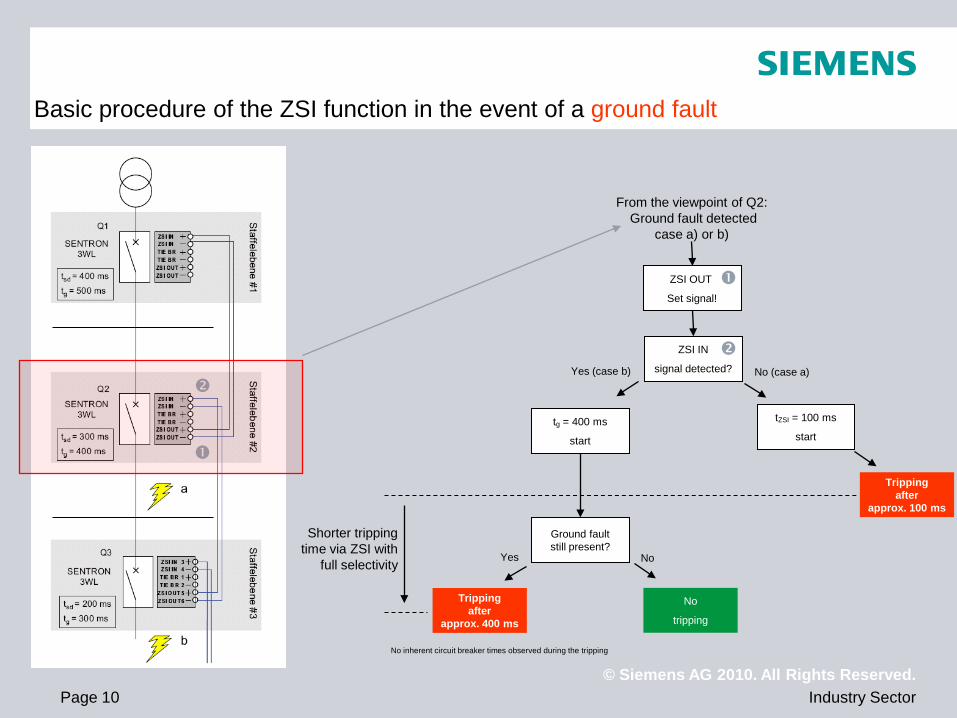
Basic procedure of the ZSI function in the event of a ground fault
No inherent circuit breaker times observed during the tripping
ZSI OUT
Set signal!
From the viewpoint of Q2: Ground fault detected
case a) or b)
ZSI IN
signal detected?
tZSI = 100 ms
start
Tripping after
approx. 100 ms
No
tripping
tg = 400 ms
start
Ground fault still present?
Tripping after
approx. 400 ms
Shorter tripping time via ZSI with
full selectivity
Yes (case b) No (case a)
Yes No
© Siemens AG 2010. All Rights Reserved. Industry Sector Page 11
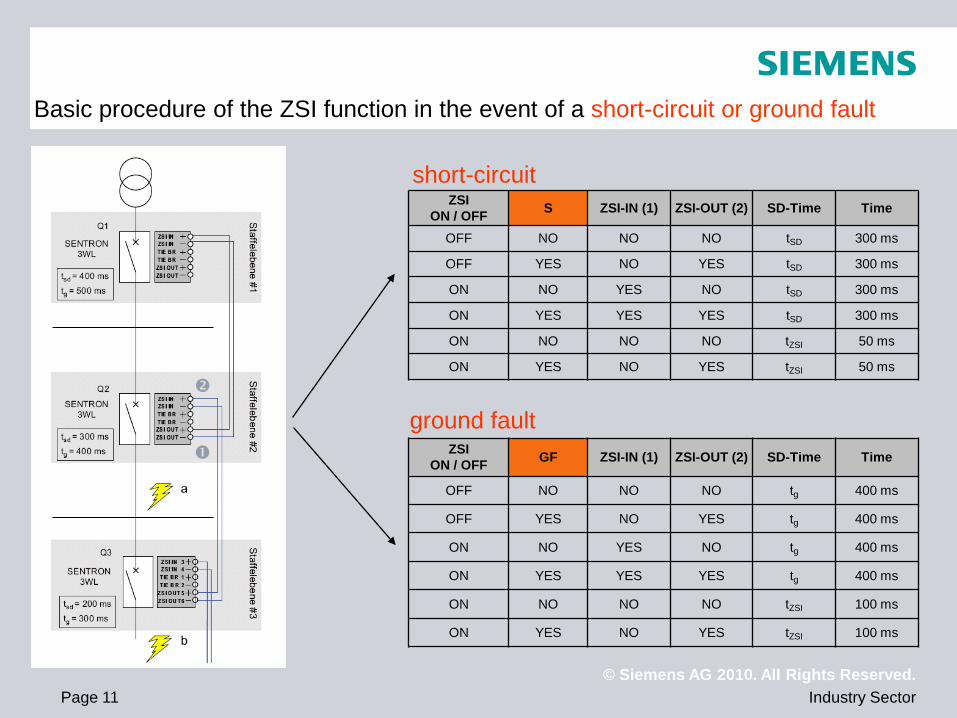
Basic procedure of the ZSI function in the event of a short-circuit or ground fault
ZSI ON / OFF S ZSI-IN (1) ZSI-OUT (2) SD-Time Time
OFF NO NO NO tSD 300 ms
OFF YES NO YES tSD 300 ms
ON NO YES NO tSD 300 ms
ON YES YES YES tSD 300 ms
ON NO NO NO tZSI 50 ms
ON YES NO YES tZSI 50 ms
ZSI ON / OFF GF ZSI-IN (1) ZSI-OUT (2) SD-Time Time
OFF NO NO NO tg 400 ms
OFF YES NO YES tg 400 ms
ON NO YES NO tg 400 ms
ON YES YES YES tg 400 ms
ON NO NO NO tZSI 100 ms
ON YES NO YES tZSI 100 ms
ground fault
short-circuit
© Siemens AG 2010. All Rights Reserved. Industry Sector Page 12
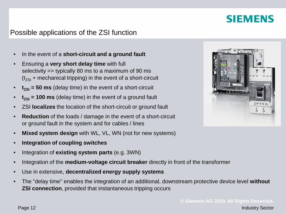
Possible applications of the ZSI function
• In the event of a short-circuit and a ground fault
• Ensuring a very short delay time with full selectivity => typically 80 ms to a maximum of 90 ms (tZSI + mechanical tripping) in the event of a short-circuit
• tZSI = 50 ms (delay time) in the event of a short-circuit
• tZSI = 100 ms (delay time) in the event of a ground fault
• ZSI localizes the location of the short-circuit or ground fault
• Reduction of the loads / damage in the event of a short-circuit or ground fault in the system and for cables / lines
• Mixed system design with WL, VL, WN (not for new systems)
• Integration of coupling switches
• Integration of existing system parts (e.g. 3WN)
• Integration of the medium-voltage circuit breaker directly in front of the transformer
• Use in extensive, decentralized energy supply systems
• The "delay time" enables the integration of an additional, downstream protective device level without ZSI connection, provided that instantaneous tripping occurs
© Siemens AG 2010. All Rights Reserved. Industry Sector Page 13
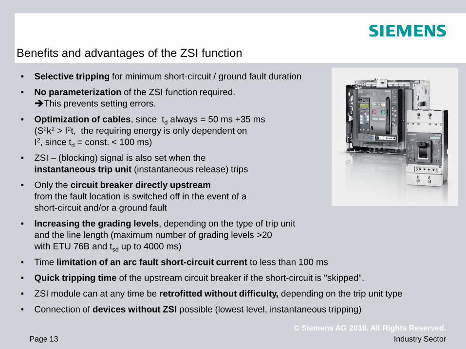
Benefits and advantages of the ZSI function
• Selective tripping for minimum short-circuit / ground fault duration
• No parameterization of the ZSI function required. This prevents setting errors.
• Optimization of cables, since td always = 50 ms +35 ms (S2k2 > I2t, the requiring energy is only dependent on I2, since td = const. < 100 ms)
• ZSI – (blocking) signal is also set when the instantaneous trip unit (instantaneous release) trips
• Only the circuit breaker directly upstream from the fault location is switched off in the event of a short-circuit and/or a ground fault
• Increasing the grading levels, depending on the type of trip unit and the line length (maximum number of grading levels >20 with ETU 76B and tsd up to 4000 ms)
• Time limitation of an arc fault short-circuit current to less than 100 ms
• Quick tripping time of the upstream circuit breaker if the short-circuit is "skipped".
• ZSI module can at any time be retrofitted without difficulty, depending on the trip unit type
• Connection of devices without ZSI possible (lowest level, instantaneous tripping)
© Siemens AG 2010. All Rights Reserved. Industry Sector Page 14
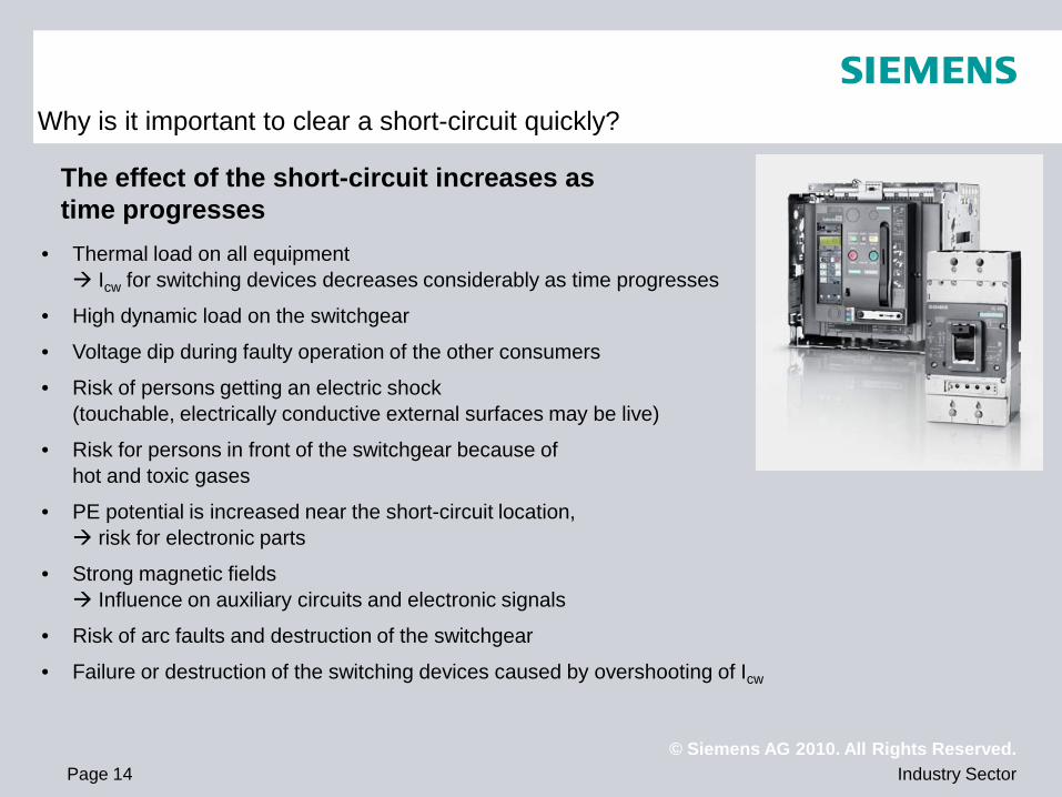
Why is it important to clear a short-circuit quickly?
• Thermal load on all equipment Icw for switching devices decreases considerably as time progresses
• High dynamic load on the switchgear
• Voltage dip during faulty operation of the other consumers
• Risk of persons getting an electric shock (touchable, electrically conductive external surfaces may be live)
• Risk for persons in front of the switchgear because of hot and toxic gases
• PE potential is increased near the short-circuit location, risk for electronic parts
• Strong magnetic fields Influence on auxiliary circuits and electronic signals
• Risk of arc faults and destruction of the switchgear
• Failure or destruction of the switching devices caused by overshooting of Icw
The effect of the short-circuit increases as time progresses
© Siemens AG 2010. All Rights Reserved. Industry Sector Page 15
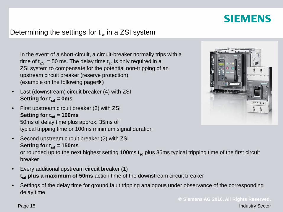
Determining the settings for tsd in a ZSI system
In the event of a short-circuit, a circuit-breaker normally trips with a time of tZSI = 50 ms. The delay time tsd is only required in a ZSI system to compensate for the potential non-tripping of an upstream circuit breaker (reserve protection). (example on the following page)
• Last (downstream) circuit breaker (4) with ZSI Setting for tsd = 0ms
• First upstream circuit breaker (3) with ZSI Setting for tsd = 100ms 50ms of delay time plus approx. 35ms of typical tripping time or 100ms minimum signal duration
• Second upstream circuit breaker (2) with ZSI Setting for tsd = 150ms or rounded up to the next highest setting 100ms tsd plus 35ms typical tripping time of the first circuit breaker
• Every additional upstream circuit breaker (1) tsd plus a maximum of 50ms action time of the downstream circuit breaker
• Settings of the delay time for ground fault tripping analogous under observance of the corresponding delay time
© Siemens AG 2010. All Rights Reserved. Industry Sector Page 16
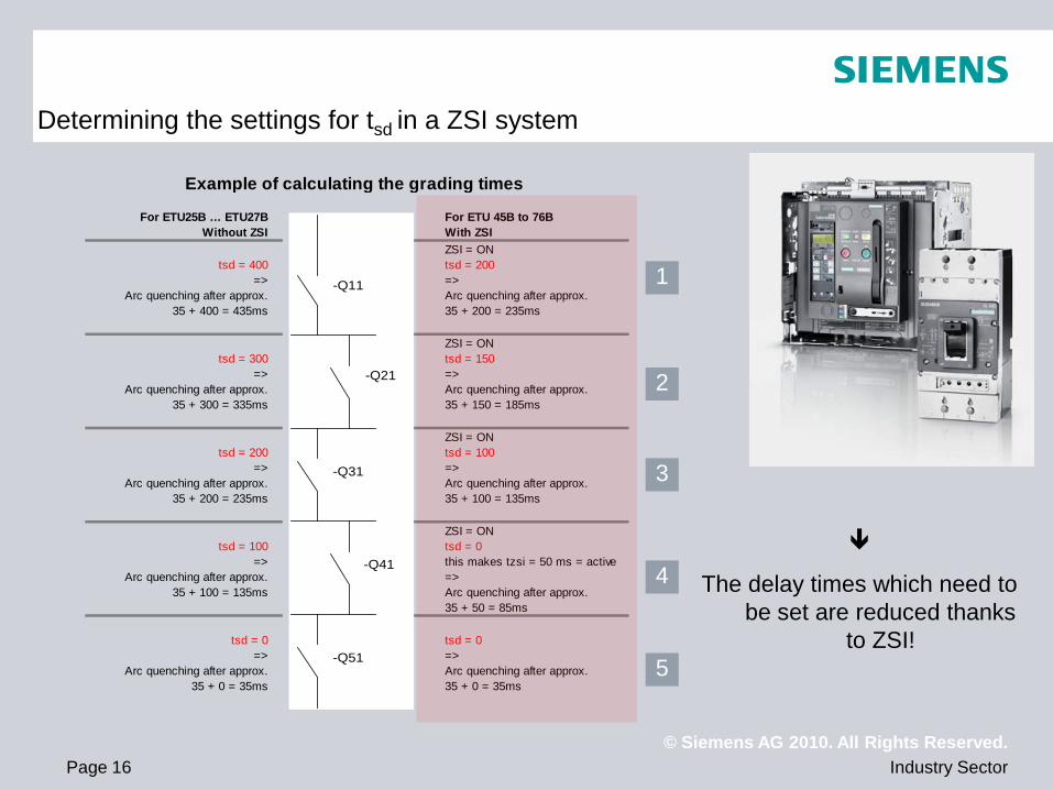
For ETU25B … ETU27B For ETU 45B to 76BWithout ZSI With ZSI
ZSI = ONtsd = 400 tsd = 200
=> =>Arc quenching after approx. Arc quenching after approx.
35 + 400 = 435ms 35 + 200 = 235ms
ZSI = ONtsd = 300 tsd = 150
=> =>Arc quenching after approx. Arc quenching after approx.
35 + 300 = 335ms 35 + 150 = 185ms
ZSI = ONtsd = 200 tsd = 100
=> =>Arc quenching after approx. Arc quenching after approx.
35 + 200 = 235ms 35 + 100 = 135ms
ZSI = ONtsd = 100 tsd = 0
=> this makes tzsi = 50 ms = activeArc quenching after approx. =>
35 + 100 = 135ms Arc quenching after approx.35 + 50 = 85ms
tsd = 0 tsd = 0=> =>
Arc quenching after approx. Arc quenching after approx.35 + 0 = 35ms 35 + 0 = 35ms
Example of calculating the grading times
-Q11
-Q21
-Q31
-Q41
-Q51
Determining the settings for tsd in a ZSI system
The delay times which need to be set are reduced thanks
to ZSI!
1
2
3
4
5
© Siemens AG 2010. All Rights Reserved. Industry Sector Page 17
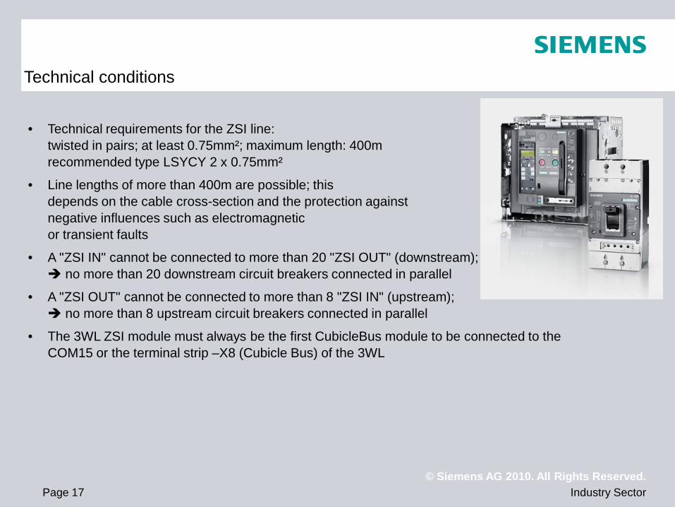
Technical conditions
• Technical requirements for the ZSI line: twisted in pairs; at least 0.75mm²; maximum length: 400m recommended type LSYCY 2 x 0.75mm²
• Line lengths of more than 400m are possible; this depends on the cable cross-section and the protection against negative influences such as electromagnetic or transient faults
• A "ZSI IN" cannot be connected to more than 20 "ZSI OUT" (downstream); no more than 20 downstream circuit breakers connected in parallel
• A "ZSI OUT" cannot be connected to more than 8 "ZSI IN" (upstream); no more than 8 upstream circuit breakers connected in parallel
• The 3WL ZSI module must always be the first CubicleBus module to be connected to the COM15 or the terminal strip –X8 (Cubicle Bus) of the 3WL
© Siemens AG 2010. All Rights Reserved. Industry Sector Page 18
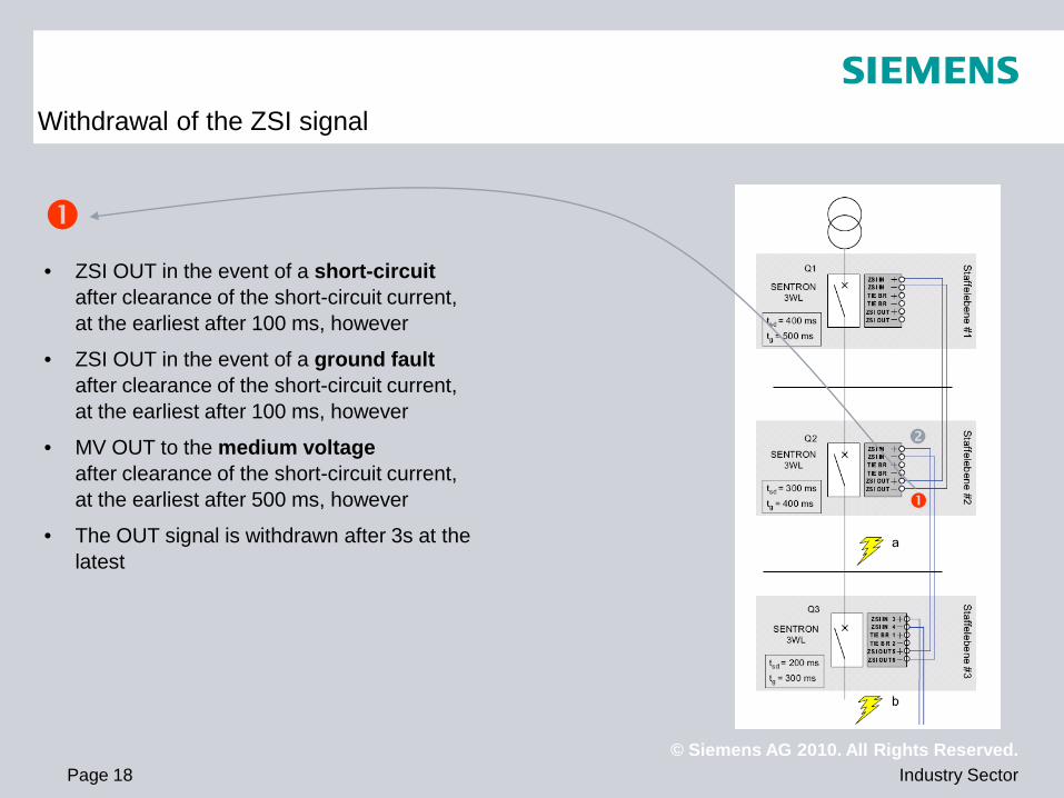
Withdrawal of the ZSI signal
• ZSI OUT in the event of a short-circuit
after clearance of the short-circuit current, at the earliest after 100 ms, however
• ZSI OUT in the event of a ground fault after clearance of the short-circuit current, at the earliest after 100 ms, however
• MV OUT to the medium voltage after clearance of the short-circuit current, at the earliest after 500 ms, however
• The OUT signal is withdrawn after 3s at the latest
© Siemens AG 2010. All Rights Reserved. Industry Sector Page 19
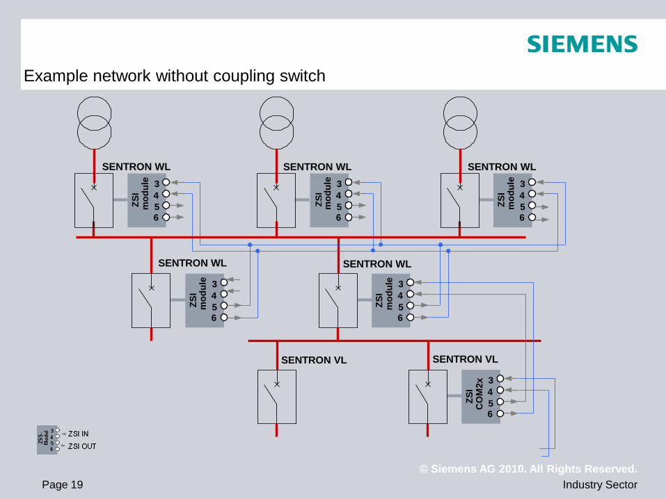
Example network without coupling switch
3 4 5 6
ZSI
mod
ule
SENTRON WL 3 4 5 6
SENTRON WL
ZSI
mod
ule 3
4 5 6
SENTRON WL
ZSI
mod
ule
3 4 5 6
SENTRON VL
ZSI
CO
M2x
3 4 5 6
SENTRON WL
ZSI
mod
ule 3
4 5 6
SENTRON WL
ZSI
mod
ule
SENTRON VL
© Siemens AG 2010. All Rights Reserved. Industry Sector Page 20
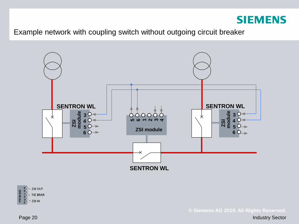
Example network with coupling switch without outgoing circuit breaker
3 4 5 6
ZSI
mod
ule
SENTRON WL 3 4 5 6
SENTRON WL
ZSI
mod
ule
1 2 3 4 SENTRON WL
ZSI module 5 6
© Siemens AG 2010. All Rights Reserved. Industry Sector Page 21
Example network with coupling switch and outgoing circuit breaker
3 4 5 6
ZSI
mod
ule
SENTRON WL 3 4 5 6
SENTRON WL
ZSI
mod
ule
3 4 5 6
SENTRON WL
ZSI
mod
ule 3
4 5 6
SENTRON WL
ZSI
mod
ule
1 2 3 4
SENTRON WL
ZSI module
5 6
© Siemens AG 2010. All Rights Reserved. Industry Sector Page 22
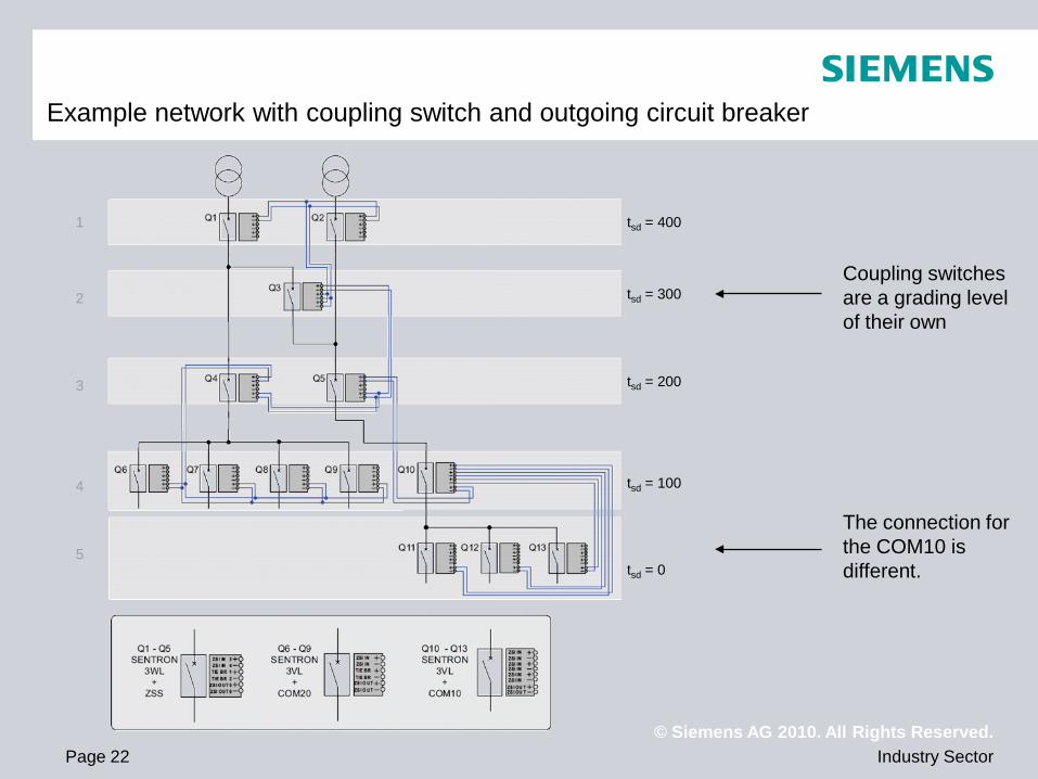
Example network with coupling switch and outgoing circuit breaker
Coupling switches are a grading level of their own
The connection for the COM10 is different.
1
2
3
4
5 tsd = 0
tsd = 100
tsd = 200
tsd = 300
tsd = 400
© Siemens AG 2010. All Rights Reserved. Industry Sector Page 23
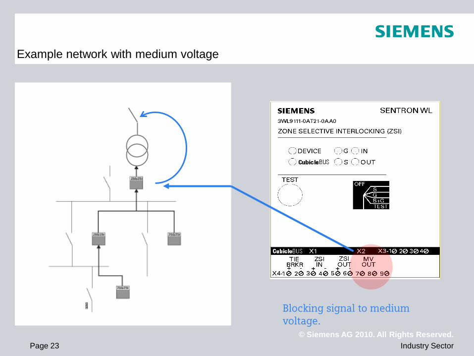
Example network with medium voltage
Blocking signal to medium voltage.
© Siemens AG 2010. All Rights Reserved. Industry Sector Page 24
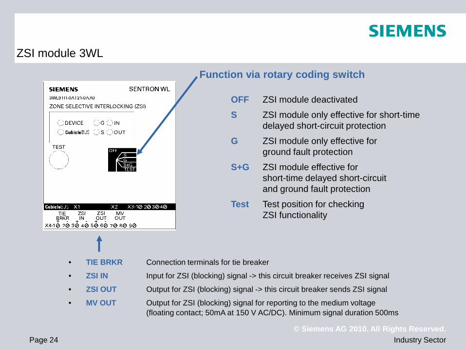
ZSI module 3WL
OFF ZSI module deactivated
S ZSI module only effective for short-time delayed short-circuit protection
G ZSI module only effective for ground fault protection
S+G ZSI module effective for short-time delayed short-circuit and ground fault protection
Test Test position for checking ZSI functionality
Function via rotary coding switch
• TIE BRKR Connection terminals for tie breaker
• ZSI IN Input for ZSI (blocking) signal -> this circuit breaker receives ZSI signal
• ZSI OUT Output for ZSI (blocking) signal -> this circuit breaker sends ZSI signal
• MV OUT Output for ZSI (blocking) signal for reporting to the medium voltage (floating contact; 50mA at 150 V AC/DC). Minimum signal duration 500ms
© Siemens AG 2010. All Rights Reserved. Industry Sector Page 25
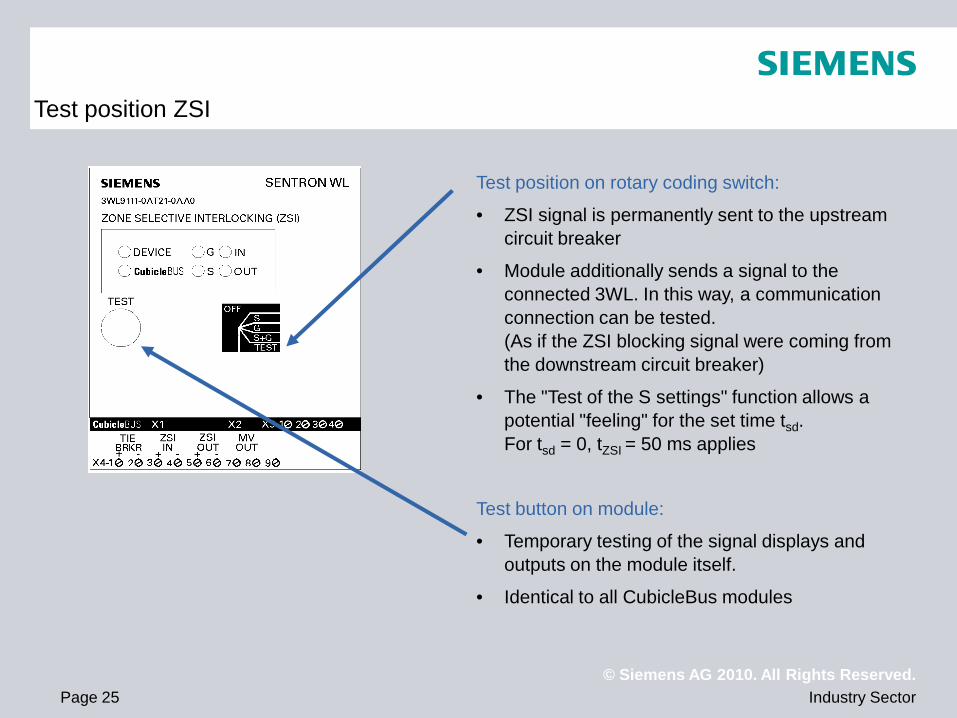
Test position ZSI
Test position on rotary coding switch:
• ZSI signal is permanently sent to the upstream circuit breaker
• Module additionally sends a signal to the connected 3WL. In this way, a communication connection can be tested. (As if the ZSI blocking signal were coming from the downstream circuit breaker)
• The "Test of the S settings" function allows a potential "feeling" for the set time tsd. For tsd = 0, tZSI = 50 ms applies
Test button on module:
• Temporary testing of the signal displays and outputs on the module itself.
• Identical to all CubicleBus modules
© Siemens AG 2010. All Rights Reserved. Industry Sector Page 26
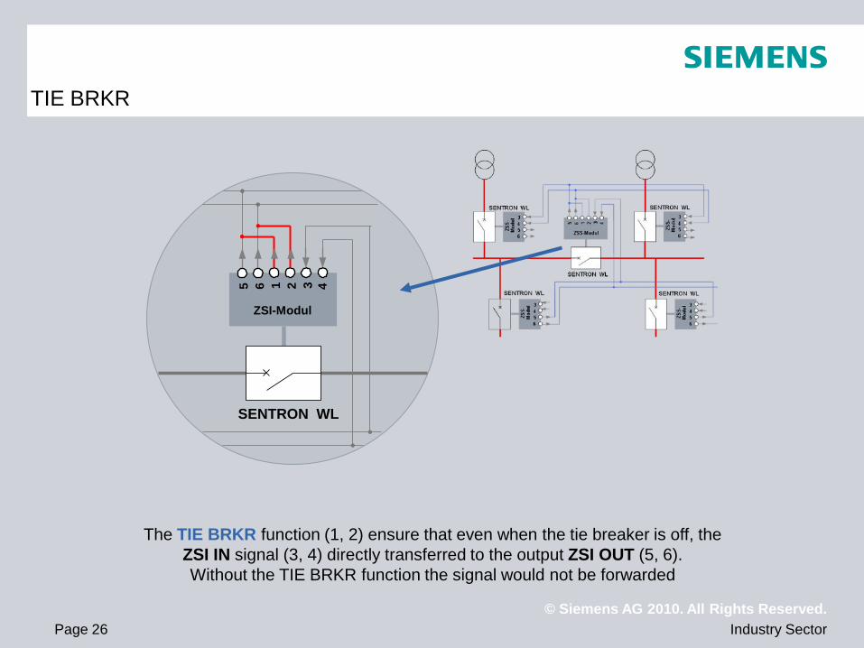
TIE BRKR
The TIE BRKR function (1, 2) ensure that even when the tie breaker is off, the ZSI IN signal (3, 4) directly transferred to the output ZSI OUT (5, 6). Without the TIE BRKR function the signal would not be forwarded
1 2 3 4
SENTRON WL
ZSI-Modul
5 6
© Siemens AG 2010. All Rights Reserved. Industry Sector Page 27
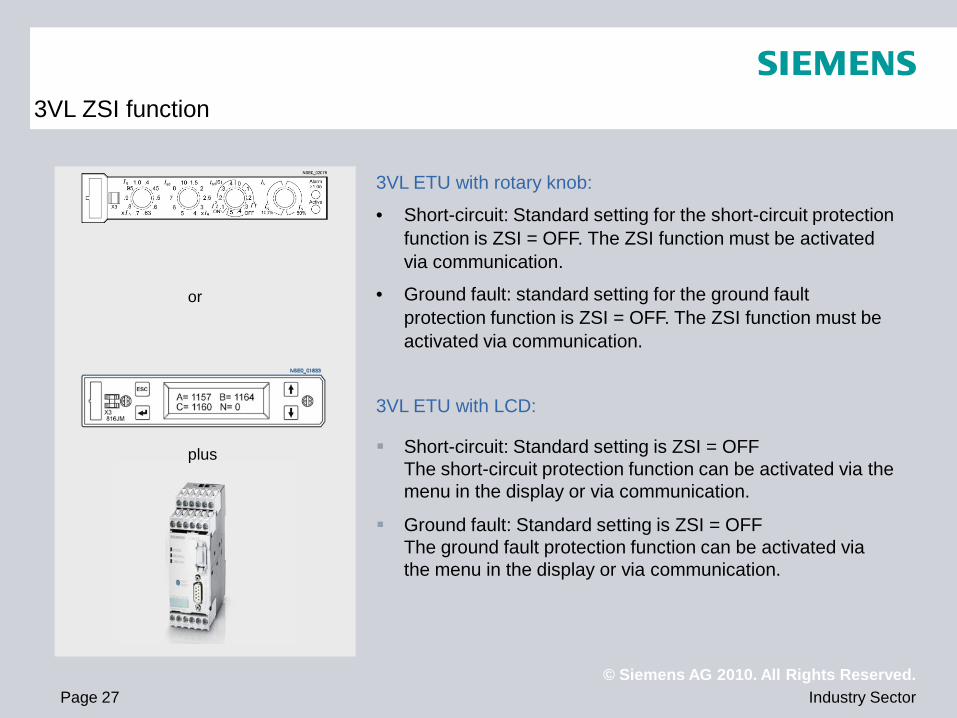
3VL ZSI function
3VL ETU with rotary knob:
• Short-circuit: Standard setting for the short-circuit protection function is ZSI = OFF. The ZSI function must be activated via communication.
• Ground fault: standard setting for the ground fault protection function is ZSI = OFF. The ZSI function must be activated via communication.
3VL ETU with LCD:
Short-circuit: Standard setting is ZSI = OFF The short-circuit protection function can be activated via the menu in the display or via communication.
Ground fault: Standard setting is ZSI = OFF The ground fault protection function can be activated via the menu in the display or via communication.
or
plus
© Siemens AG 2010. All Rights Reserved. Industry Sector Page 28
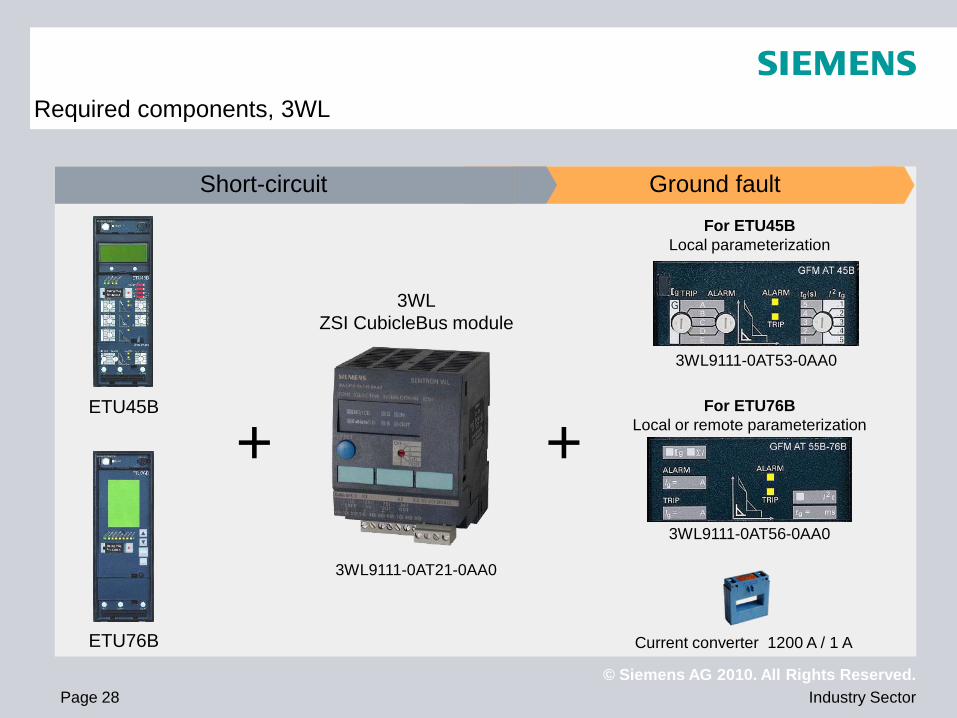
ETU45B
ETU76B
3WL ZSI CubicleBus module
+ 3WL9111-0AT53-0AA0
For ETU45B Local parameterization
For ETU76B Local or remote parameterization
3WL9111-0AT56-0AA0
+
Short-circuit Ground fault
Current converter 1200 A / 1 A
3WL9111-0AT21-0AA0
Required components, 3WL
© Siemens AG 2010. All Rights Reserved. Industry Sector Page 29
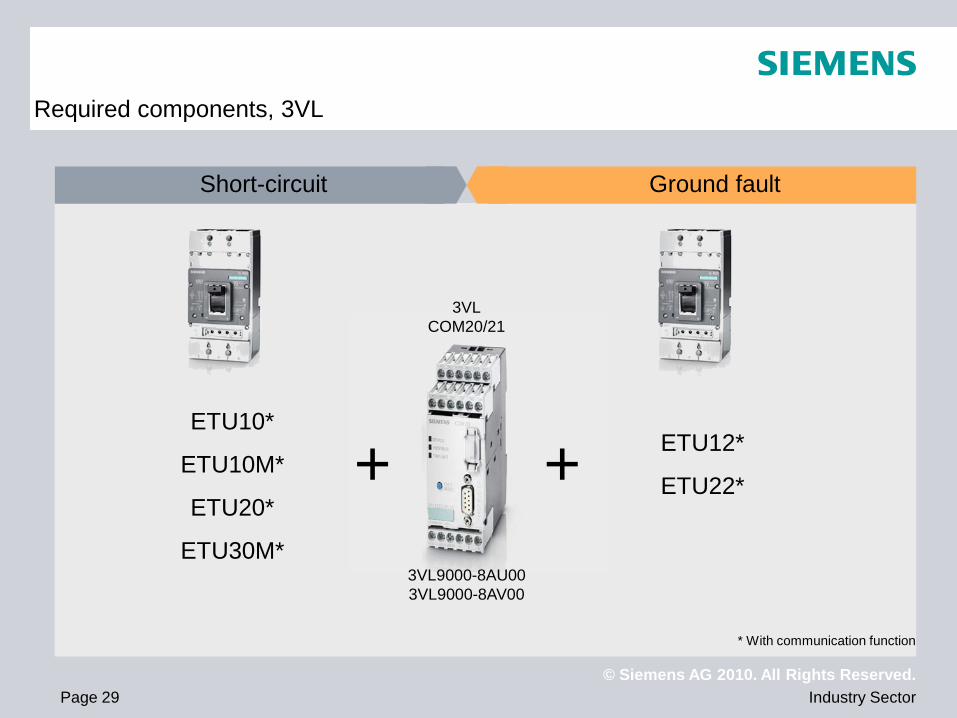
Short-circuit Ground fault
3VL COM20/21
+ + 3VL9000-8AU00 3VL9000-8AV00
ETU10*
ETU10M*
ETU20*
ETU30M*
ETU12*
ETU22*
* With communication function
Required components, 3VL
© Siemens AG 2010. All Rights Reserved. Industry Sector Page 30
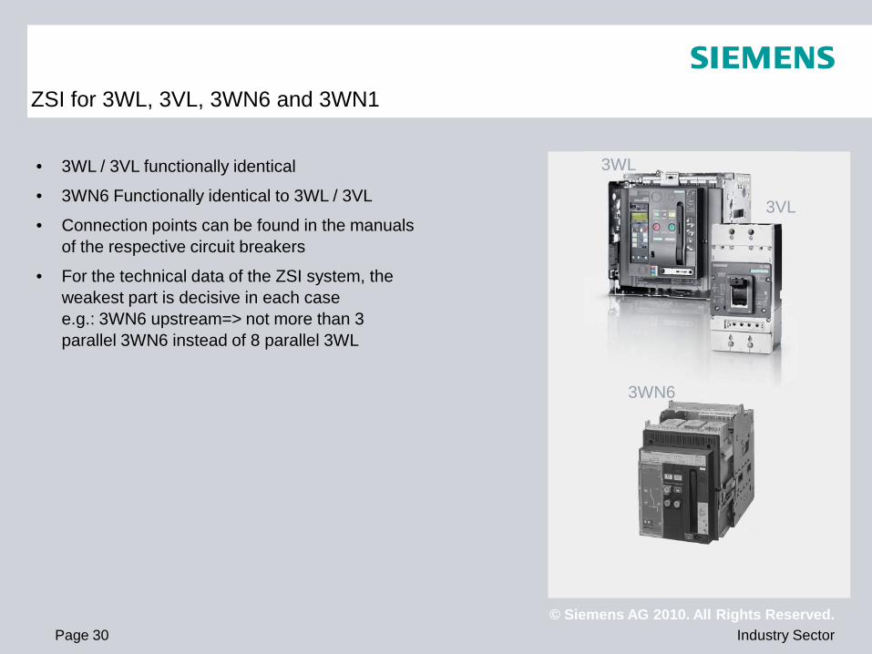
ZSI for 3WL, 3VL, 3WN6 and 3WN1
• 3WL / 3VL functionally identical
• 3WN6 Functionally identical to 3WL / 3VL
• Connection points can be found in the manuals of the respective circuit breakers
• For the technical data of the ZSI system, the weakest part is decisive in each case e.g.: 3WN6 upstream=> not more than 3 parallel 3WN6 instead of 8 parallel 3WL
3WL
3VL
3WN6
© Siemens AG 2010. All Rights Reserved. Industry Sector Page 31
ZSI
ZSI
ZSI
ZSI
ZSI
ZSI
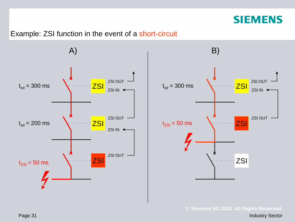
tZSI = 50 ms
tsd = 200 ms
tsd = 300 ms
ZSI
ZSI
ZSI
ZSI
ZSI
tZSI = 50 ms
tsd = 300 ms
A) B)
Example: ZSI function in the event of a short-circuit
ZSI OUT
ZSI OUT
ZSI IN
ZSI IN
ZSI OUT
ZSI OUT
ZSI IN
ZSI OUT
ZSI
ZSI
© Siemens AG 2010. All Rights Reserved. Industry Sector Page 32
ZSI
ZSI
ZSI
ZSI
ZSI
ZSI
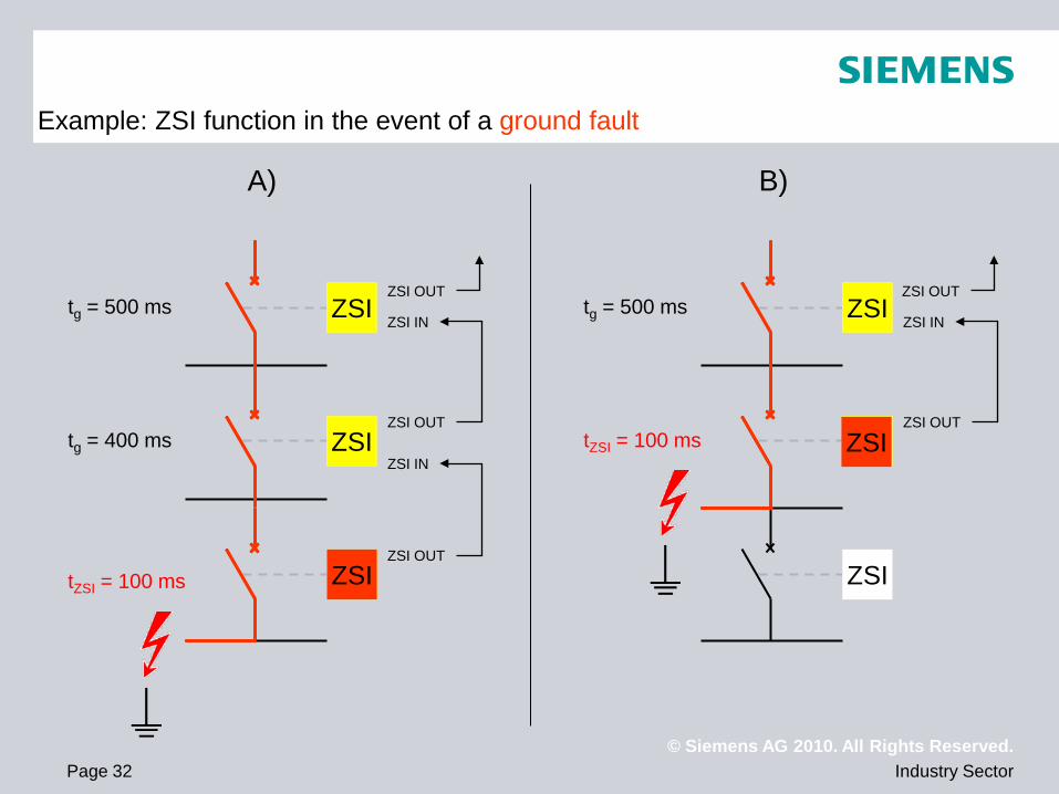
tZSI = 100 ms
tg = 400 ms
tg = 500 ms
ZSI
ZSI
ZSI
ZSI
ZSI
tZSI = 100 ms
tg = 500 ms
A) B)
Example: ZSI function in the event of a ground fault
ZSI OUT
ZSI OUT
ZSI IN
ZSI IN
ZSI OUT
ZSI OUT
ZSI IN
ZSI OUT
ZSI
ZSI
© Siemens AG 2010. All Rights Reserved. Industry Sector Page 33
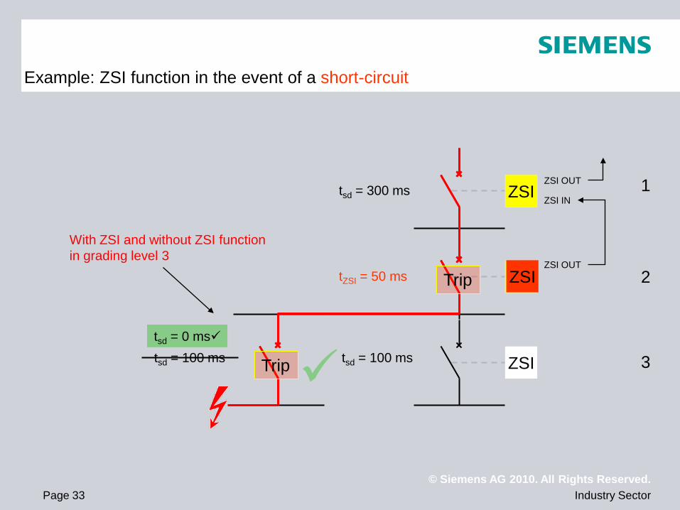
tsd = 200 ms
ZSI
ZSI
ZSI
ZSI
ZSI
tZSI = 50 ms
tsd = 300 ms
Example: ZSI function in the event of a short-circuit
ZSI OUT
ZSI IN
ZSI OUT
tsd = 100 ms
ZSI Trip
tsd = 0 ms tsd = 100 ms Trip
With ZSI and without ZSI function in grading level 3
1
2
3
© Siemens AG 2010. All Rights Reserved. Industry Sector Page 34
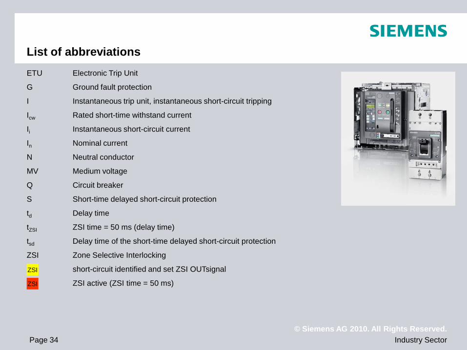
ETU Electronic Trip Unit
G Ground fault protection
I Instantaneous trip unit, instantaneous short-circuit tripping
Icw Rated short-time withstand current
Ii Instantaneous short-circuit current
In Nominal current
N Neutral conductor
MV Medium voltage
Q Circuit breaker
S Short-time delayed short-circuit protection
td Delay time
tZSI ZSI time = 50 ms (delay time)
tsd Delay time of the short-time delayed short-circuit protection
ZSI Zone Selective Interlocking
short-circuit identified and set ZSI OUTsignal
ZSI active (ZSI time = 50 ms)
ZSI
ZSI
List of abbreviations

© Siemens AG 2010. All Rights Reserved.
Rainer Huentemeier Productmanager IC LMV LV GP ACB&F V2.5 2011 Huentemeier / Pikulicki
Thank you for your attention!
Recommended