High Voltage Electrolyte for Lithium Batteries
Zhengcheng Zhang (PI) Huiming Wu, Libo Hu, and Khalil Amine
Argonne National Laboratory
Vehicle Technologies Program Annual Merit Review and Peer Evaluation Meeting
Washington, D.C. May 14-18, 2012
Project ID #: ES113
This presentation does not contain any proprietary, confidential, or otherwise restricted information
Project Overview
2
Timeline Barriers
Budget Partners
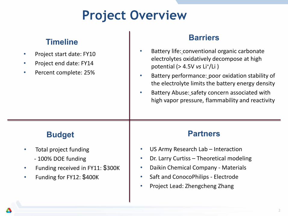
• Project start date: FY10 • Project end date: FY14 • Percent complete: 25%
• Battery life: conventional organic carbonate electrolytes oxidatively decompose at high potential (> 4.5V vs Li+/Li )
• Battery performance: poor oxidation stability of the electrolyte limits the battery energy density
• Battery Abuse: safety concern associated with high vapor pressure, flammability and reactivity
• Total project funding - 100% DOE funding • Funding received in FY11: $300K • Funding for FY12: $400K
• US Army Research Lab – Interaction • Dr. Larry Curtiss – Theoretical modeling • Daikin Chemical Company - Materials • Saft and ConocoPhilips - Electrode • Project Lead: Zhengcheng Zhang
3 3
Project Objective The objective of this project is to develop advanced electrolyte materials that can significantly
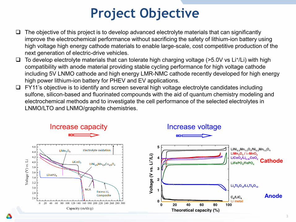
improve the electrochemical performance without sacrificing the safety of lithium-ion battery using high voltage high energy cathode materials to enable large-scale, cost competitive production of the next generation of electric-drive vehicles.
To develop electrolyte materials that can tolerate high charging voltage (>5.0V vs Li+/Li) with high compatibility with anode material providing stable cycling performance for high voltage cathode including 5V LNMO cathode and high energy LMR-NMC cathode recently developed for high energy high power lithium-ion battery for PHEV and EV applications.
FY11’s objective is to identify and screen several high voltage electrolyte candidates including sulfone, silicon-based and fluorinated compounds with the aid of quantum chemistry modeling and electrochemical methods and to investigate the cell performance of the selected electrolytes in LNMO/LTO and LNMO/graphite chemistries.
Increase capacity Increase voltage
Cathode
Anode
4
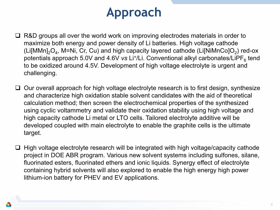
R&D groups all over the world work on improving electrodes materials in order to maximize both energy and power density of Li batteries. High voltage cathode (Li[MMn]2O4, M=Ni, Cr, Cu) and high capacity layered cathode (Li[NiMnCo]O2) red-ox potentials approach 5.0V and 4.6V vs Li+/Li. Conventional alkyl carbonates/LiPF6 tend to be oxidized around 4.5V. Development of high voltage electrolyte is urgent and challenging.
Our overall approach for high voltage electrolyte research is to first design, synthesize and characterize high oxidation stable solvent candidates with the aid of theoretical calculation method; then screen the electrochemical properties of the synthesized using cyclic voltammetry and validate their oxidation stability using high voltage and high capacity cathode Li metal or LTO cells. Tailored electrolyte additive will be developed coupled with main electrolyte to enable the graphite cells is the ultimate target.
High voltage electrolyte research will be integrated with high voltage/capacity cathode project in DOE ABR program. Various new solvent systems including sulfones, silane, fluorinated esters, fluorinated ethers and ionic liquids. Synergy effect of electrolyte containing hybrid solvents will also explored to enable the high energy high power lithium-ion battery for PHEV and EV applications.
Approach
5
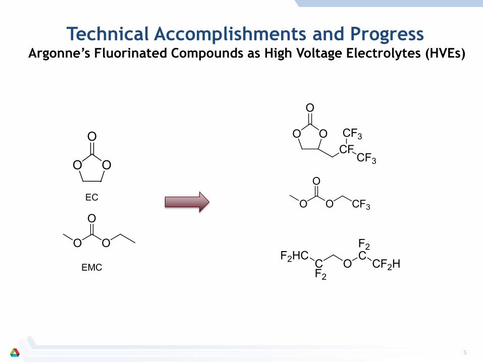
Technical Accomplishments and Progress Argonne’s Fluorinated Compounds as High Voltage Electrolytes (HVEs)
O
OO
O
O O
EC
EMC
OO
O
CFCF3
CF3
O
OO CF3
F2HCCF2
O
F2C
CF2H
6
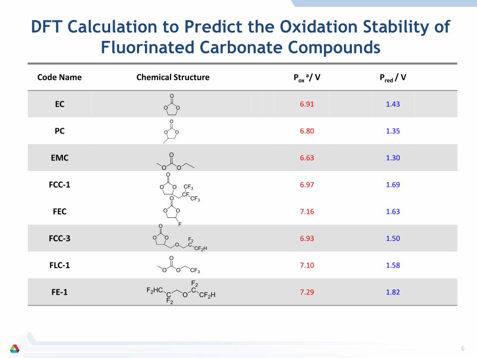
Code Name Chemical Structure Pox a/ V Pred / V
EC 6.91 1.43
PC 6.80 1.35
EMC 6.63 1.30
FCC-1 6.97 1.69
FEC 7.16 1.63
FCC-3 6.93 1.50
FLC-1 7.10 1.58
FE-1 7.29 1.82
DFT Calculation to Predict the Oxidation Stability of Fluorinated Carbonate Compounds
O
OO
O
OO
O
O O
OO
O
CFCF3
CF3
OO
O
F
OO
O
OF2C
CF2H
O
OO CF3
F2HCCF2
O
F2C
CF2H
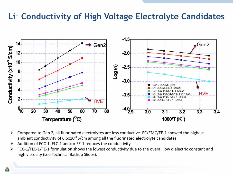
Li+ Conductivity of High Voltage Electrolyte Candidates
Compared to Gen 2, all fluorinated electrolytes are less conductive. EC/EMC/FE-1 showed the highest ambient conductivity of 6.5x10⁻³ S/cm among all the fluorinated electrolyte candidates.
Addition of FCC-1, FLC-1 and/or FE-1 reduces the conductivity. FCC-1/FLC-1/FE-1 formulation shows the lowest conductivity due to the overall low dielectric constant and
high viscosity (see Technical Backup Slides).
10 20 30 40 50 60 70 800
2
4
6
8
10
12
14
Cond
uctiv
ity (x
10-3 S
/cm
)
Temperature (OC)2.9 3.0 3.1 3.2 3.3 3.4-4.0
-3.5
-3.0
-2.5
-2.0
-1.5
Gen 2 EC/EMC (3:7) E1: EC/EMC/FE-1 (2:6:2) E3: FCC-1/EMC/FE-1 (2:6:2) E4: FCC-1/EC/EMC/FE-1 (1:1:6:2) E5: FCC-1/FLC-1/FE-1 (2:6:2) E6: EC/FLC-1/FE-1 (2:6:2)
Log
(α)
1000/T (K-1)
Gen2
HVE
Gen2
HVE
8
0 100 200 300 400 500 600 7000.000
0.010
0.020
0.030
0.040
0.050
0.060
0.070
0.080
5.6V
5.7V
5.0-5.4V
6.0~6.4V
5.8V
Gen2 (EC/EMC = 3:7)
5.5V
5.9V
Time (s)
I (m
A/c
m-2)
0 100 200 300 400 500 600 7000.00
0.01
0.02
0.03
0.04
0.05
0.06
0.07
0.08
E1 (EC/EMC/FE-1 = 2:6:2)
5.3-5.7V5.8 V
6.0 V
6.1 V
5.9 V
Time (s)0 100 200 300 400 500 600 700
0.00
0.01
0.02
0.03
0.04
0.05
0.06
0.07
0.08
E2 (EC/EMC/FE-1 = 2:5:3)
5.3-5.7V5.8 V
6.0 V6.1 V
5.9 V
Time (s)
0 100 200 300 400 500 600 700
0.000
0.010
0.020
0.030
0.040
0.050
0.060
0.070
0.080
6.1V
E4 (FCC-1/EC/EMC/FE-1 = 1:1:6:2)
5.3~5.7V5.8V
6.0V
6.2V
5.9V
Time (s)0 100 200 300 400 500 600 700
0.000
0.010
0.020
0.030
0.040
0.050
0.060
0.070
0.080
5.0~6.4V
E6 (EC/FLC-1/FE-1 = 2:6:2)
Time (s)0 100 200 300 400 500 600 700
0.000
0.010
0.020
0.030
0.040
0.050
0.060
0.070
0.080
E5 (FCC-1/FLC-1/FE-1 = 2:6:2)
5.3-6.2 V
Time (s)
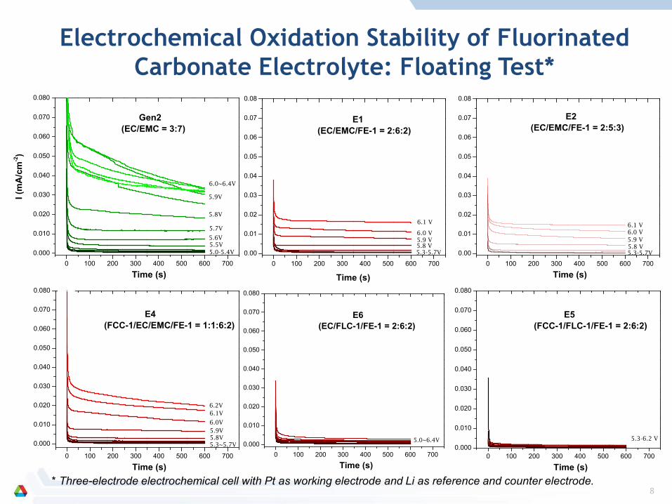
Electrochemical Oxidation Stability of Fluorinated Carbonate Electrolyte: Floating Test*
* Three-electrode electrochemical cell with Pt as working electrode and Li as reference and counter electrode.
9
0 100 200 300 400 500 6000.000
0.010
0.020
0.030
0.040
0.050
0.060
0.070
0.080
Gen 2 E1-E6
5.3 V
Time (s)
I (m
A/c
m-2
)
0 100 200 300 400 500 6000.000
0.010
0.020
0.030
0.040
0.050
0.060
0.070
0.080
E1~E6
E3
Gen 2
5.7 V
Time (s)
0 100 200 300 400 500 6000.000
0.010
0.020
0.030
0.040
0.050
0.060
0.070
0.080
E5 E6 E1E2E4
E3
Gen 2
6.0V
Time (s)
0 100 200 300 400 500 600 700
0.000
0.010
0.020
0.030
0.040
0.050
I (m
A/c
m-2
)
5.3-6.4V
6.8 V
6.6 V
E6 (EC/FLC-1/FE-1 = 2:6:2)
6.5 V
6.7 V
Time (s)
0 100 200 300 400 500 600 7000.000
0.010
0.020
0.030
0.040
0.050
6.8 V
E5 (FCC-1/FLC-1/FE-1 = 2:6:2)
5.3-6.6V6.7 V
Time (s)
I (m
A/c
m-2
)
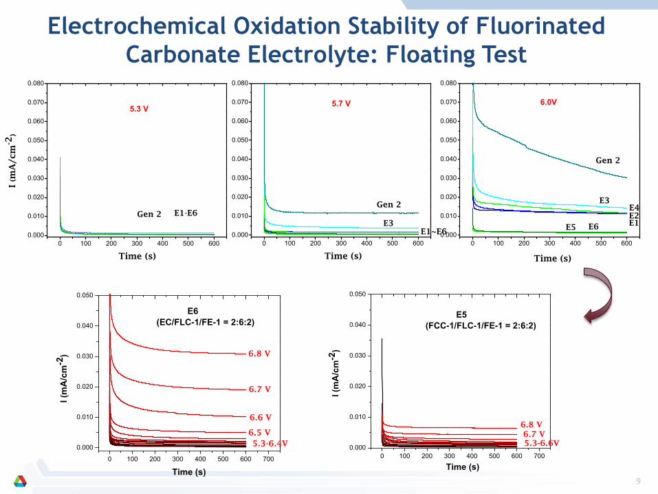
Electrochemical Oxidation Stability of Fluorinated Carbonate Electrolyte: Floating Test
10
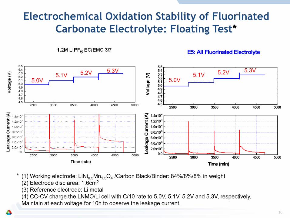
Electrochemical Oxidation Stability of Fluorinated Carbonate Electrolyte: Floating Test*
2500 3000 3500 4000 4500 50004.54.64.74.84.95.05.15.25.35.45.5
2500 3000 3500 4000 4500 50000.0
2.0x10-54.0x10-56.0x10-58.0x10-51.0x10-41.2x10-41.4x10⁻⁴
Volta
ge (V
)
Leak
age
Curr
ent (
A)
Time (min)
E5: All Fluorinated Electrolyte
(1) Working electrode: LiNi0.5Mn1.5O4 /Carbon Black/Binder: 84%/8%/8% in weight (2) Electrode disc area: 1.6cm2
(3) Reference electrode: Li metal (4) CC-CV charge the LNMO/Li cell with C/10 rate to 5.0V, 5.1V, 5.2V and 5.3V, respectively. Maintain at each voltage for 10h to observe the leakage current.
*
5.0V 5.1V 5.2V 5.3V
5.0V 5.1V 5.2V 5.3V
11
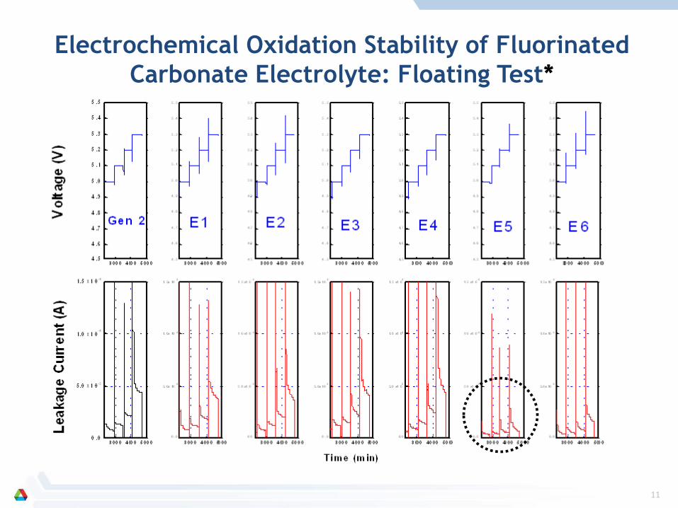
Electrochemical Oxidation Stability of Fluorinated Carbonate Electrolyte: Floating Test*
12
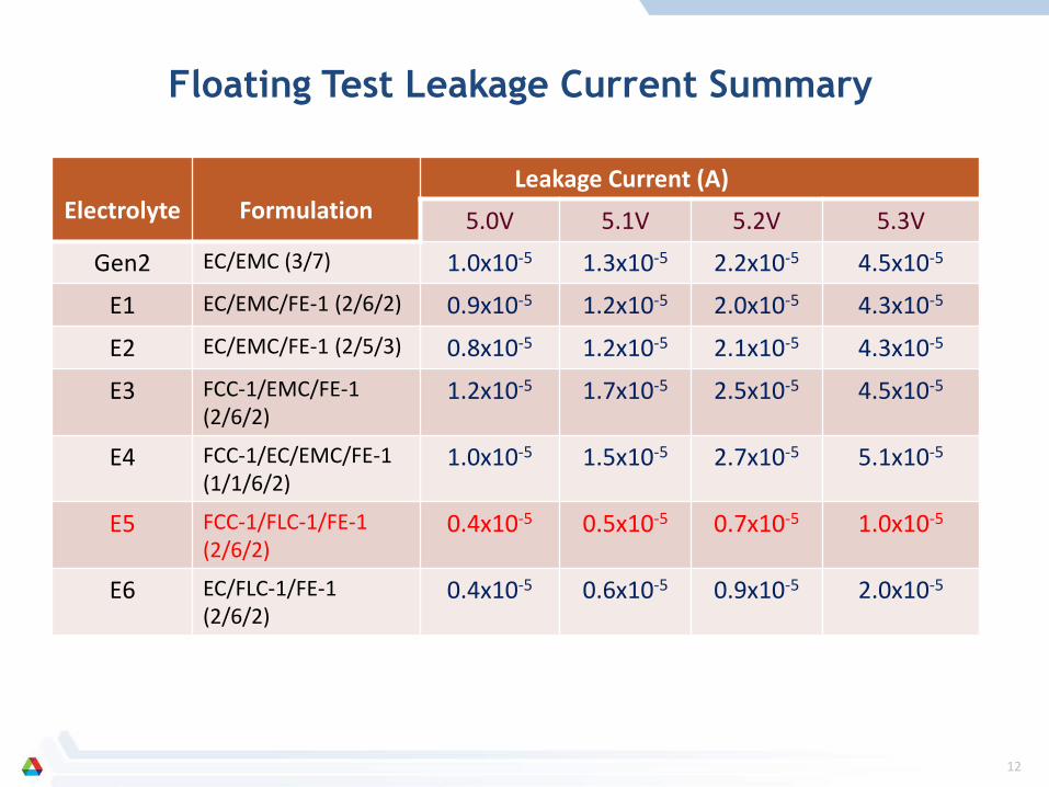
Electrolyte
Formulation
Leakage Current (A)
5.0V 5.1V 5.2V 5.3V
Gen2 EC/EMC (3/7) 1.0x10⁻⁵ 1.3x10⁻⁵ 2.2x10⁻⁵ 4.5x10⁻⁵
E1 EC/EMC/FE-1 (2/6/2) 0.9x10⁻⁵ 1.2x10⁻⁵ 2.0x10⁻⁵ 4.3x10⁻⁵
E2 EC/EMC/FE-1 (2/5/3) 0.8x10⁻⁵ 1.2x10⁻⁵ 2.1x10⁻⁵ 4.3x10⁻⁵
E3 FCC-1/EMC/FE-1 (2/6/2)
1.2x10⁻⁵ 1.7x10⁻⁵ 2.5x10⁻⁵ 4.5x10⁻⁵
E4 FCC-1/EC/EMC/FE-1 (1/1/6/2)
1.0x10⁻⁵ 1.5x10⁻⁵ 2.7x10⁻⁵ 5.1x10⁻⁵
E5 FCC-1/FLC-1/FE-1 (2/6/2)
0.4x10⁻⁵ 0.5x10⁻⁵ 0.7x10⁻⁵ 1.0x10⁻⁵
E6 EC/FLC-1/FE-1 (2/6/2)
0.4x10⁻⁵ 0.6x10⁻⁵ 0.9x10⁻⁵ 2.0x10⁻⁵
Floating Test Leakage Current Summary
13
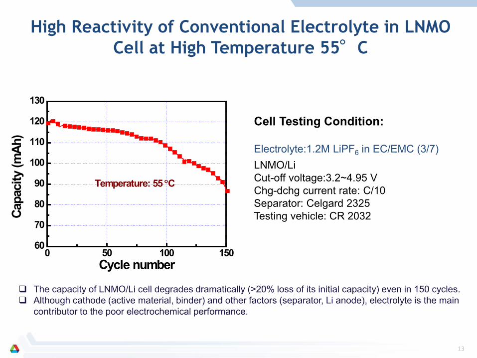
The capacity of LNMO/Li cell degrades dramatically (>20% loss of its initial capacity) even in 150 cycles. Although cathode (active material, binder) and other factors (separator, Li anode), electrolyte is the main
contributor to the poor electrochemical performance.
0 50 100 15060
70
80
90
100
110
120
130
Capa
city
(mAh
)
Cycle number
Temperature: 55 °C
Cell Testing Condition: LNMO/Li Cut-off voltage:3.2~4.95 V Chg-dchg current rate: C/10 Separator: Celgard 2325 Testing vehicle: CR 2032
Electrolyte:1.2M LiPF6 in EC/EMC (3/7)
High Reactivity of Conventional Electrolyte in LNMO Cell at High Temperature 55°C
14
25oC
0 50 100 150 200 250 300 350 4000.0
0.2
0.4
0.6
0.8
1.0
1.2
1.2M LiPF6 EC/EMC 3/7 (Gen 2 electrolyte) 1.0M LiPF6 FEC/DMC/FE-1(3/4/3 in volume)
Capa
city
(mAh
)
Cycle Number0 50 100 150 200
0.0
0.2
0.4
0.6
0.8
1.0
1.2
1.2M LiPF6 EC/EMC 3/7 (Gen 2 electrolyte) 1.0M LiPF6 FEC/DMC/FE-1(3/4/3 in volume)
Capa
city
(mAh
)
Cycle Number
55oC 2C Cycling
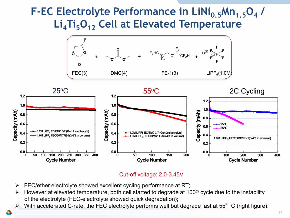
FEC/ether electrolyte showed excellent cycling performance at RT; However at elevated temperature, both cell started to degrade at 100th cycle due to the instability of the electrolyte (FEC-electrolyte showed quick degradation); With accelerated C-rate, the FEC electrolyte performs well but degrade fast at 55°C (right figure).
Cut-off voltage: 2.0-3.45V
F-EC Electrolyte Performance in LiNi0.5Mn1.5O4 / Li4Ti5O12 Cell at Elevated Temperature
O O
F
OO O
OP
F
FF
F
FFLi
FEC(3) DMC(4) FE-1(3) LiPF6(1.0M)
+ + +
0 100 200 300 4000.0
0.2
0.4
0.6
0.8
1.0
1.2
25°C 55°C
1.0M LiPF6 FEC/DMC/FE-1(3/4/3 in volume)
Capa
city
(mAh
)
Cycle Number
F2HCCF2
O
F2C
CF2H
O O
F
O
FE-1
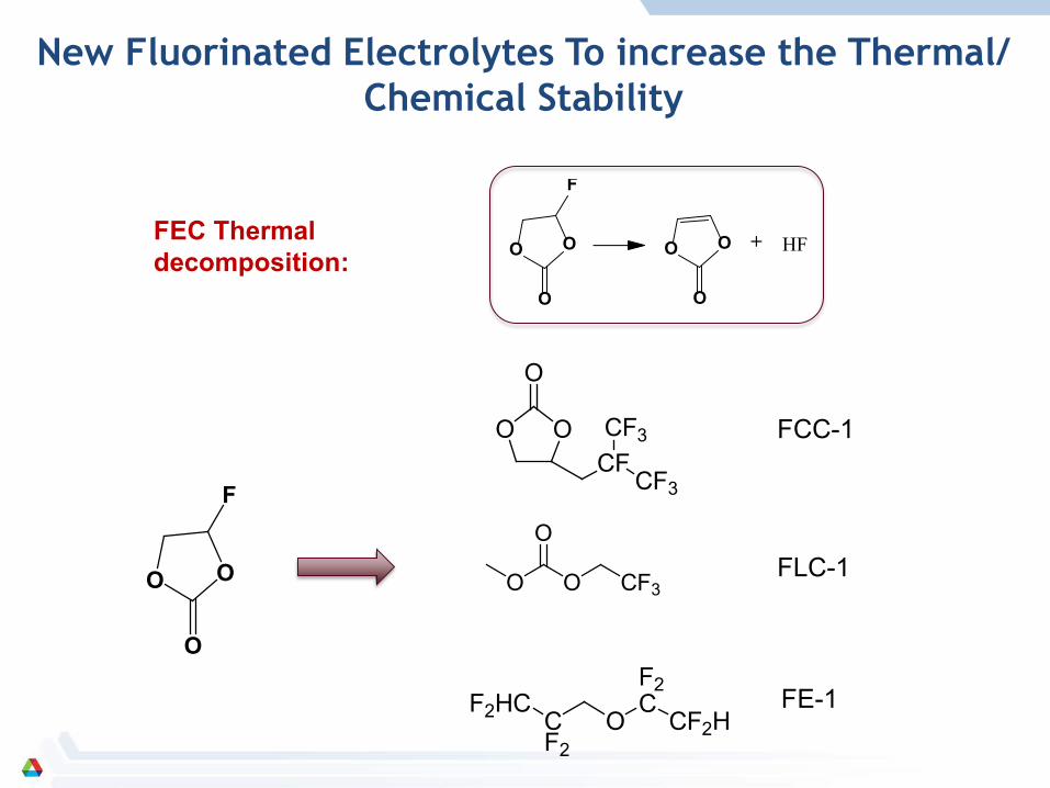
FEC Thermal decomposition: O O
F
O
O O
O
+ HF
New Fluorinated Electrolytes To increase the Thermal/ Chemical Stability
FCC-1
FLC-1
OO
O
CFCF3
CF3
O
OO CF3
F2HCCF2
O
F2C
CF2H
16
25oC
0 50 100 150 2000
20
40
60
80
100
Gen 2 electrolyte 1.0M LiPF6 FEC/DMC/FE-1(3/4/3) 1.2M LiPF6 EC/DMC/FE-1(2/6/2) 1.2M LiPF6 EC/EMC/FE-1(2/6/2)
Cap
acity
Ret
entio
n (%
)
Cycle Number0 50 100 150 200 250 300 350 400
0
20
40
60
80
100
Gen 2 electrolyte 1.0M LiPF6 FEC/DMC/FE-1(3/4/3) 1.2M LiPF6 EC/DMC/FE-1(2/6/2) 1.2M LiPF6 EC/EMC/FE-1(2/6/2)
Capa
city
Ret
entio
n (%
)
Cycle Number
55oC
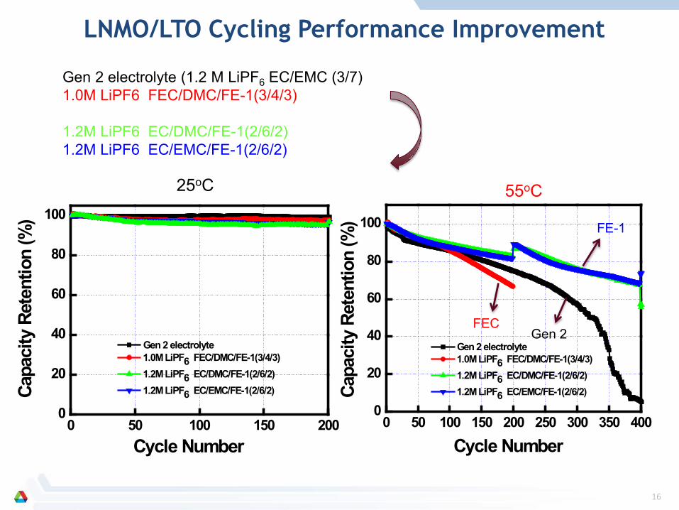
Gen 2 electrolyte (1.2 M LiPF6 EC/EMC (3/7) 1.0M LiPF6 FEC/DMC/FE-1(3/4/3) 1.2M LiPF6 EC/DMC/FE-1(2/6/2) 1.2M LiPF6 EC/EMC/FE-1(2/6/2)
FEC Gen 2
FE-1
LNMO/LTO Cycling Performance Improvement
0 20 40 60 80 10040
50
60
70
80
90
100
Gen 2 (EC/EMC (3:7) 1.2 M LiPF6
FCC-1/EMC/FE-1 (2:6:2) 1.2 M LiPF6
FCC-1/FLC-1/FE-1 (2:6:2) 1.2 M LiPF6
EC/FLC-1/FE-1 (2:6:2) 1.2 M LiPF6
Capa
city
Ret
ensi
on (%
)
Cycle Number
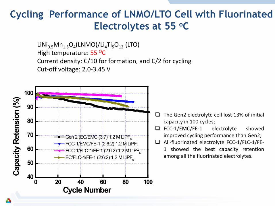
LiNi0.5Mn1.5O4(LNMO)/Li4Ti5O12 (LTO) High temperature: 55 OC Current density: C/10 for formation, and C/2 for cycling Cut-off voltage: 2.0-3.45 V
The Gen2 electrolyte cell lost 13% of initial capacity in 100 cycles;
FCC-1/EMC/FE-1 electrolyte showed improved cycling performance than Gen2;
All-fluorinated electrolyte FCC-1/FLC-1/FE-1 showed the best capacity retention among all the fluorinated electrolytes.
Cycling Performance of LNMO/LTO Cell with Fluorinated Electrolytes at 55 oC
18
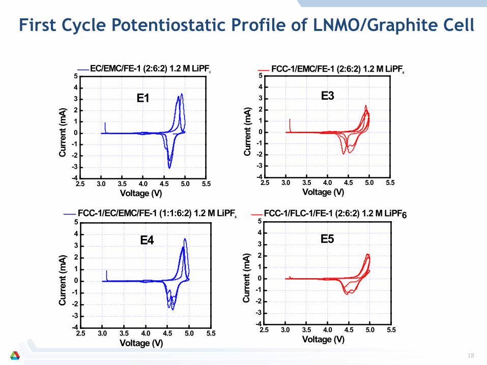
2.5 3.0 3.5 4.0 4.5 5.0 5.5-4-3-2-1012345
FCC-1/EMC/FE-1 (2:6:2) 1.2 M LiPF6
Curre
nt (m
A)
Voltage (V)
E3
2.5 3.0 3.5 4.0 4.5 5.0 5.5-4-3-2-1012345 FCC-1/EC/EMC/FE-1 (1:1:6:2) 1.2 M LiPF6
Curre
nt (m
A)
Voltage (V)
E4
2.5 3.0 3.5 4.0 4.5 5.0 5.5-4-3-2-1012345
FCC-1/FLC-1/FE-1 (2:6:2) 1.2 M LiPF6
Curre
nt (m
A)
Voltage (V)
E5
2.5 3.0 3.5 4.0 4.5 5.0 5.5-4-3-2-1012345
EC/EMC/FE-1 (2:6:2) 1.2 M LiPF6
Cu
rrent
(mA)
Voltage (V)
E1
First Cycle Potentiostatic Profile of LNMO/Graphite Cell
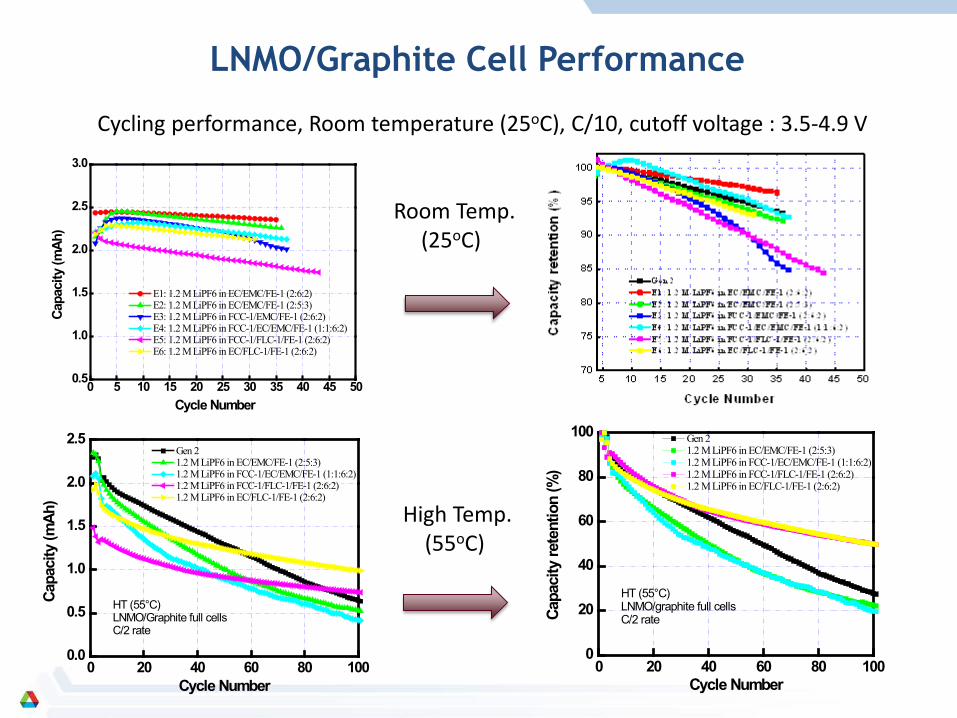
Cycling performance, Room temperature (25oC), C/10, cutoff voltage : 3.5-4.9 V
LNMO/Graphite Cell Performance
0 5 10 15 20 25 30 35 40 45 500.5
1.0
1.5
2.0
2.5
3.0
E1: 1.2 M LiPF6 in EC/EMC/FE-1 (2:6:2) E2: 1.2 M LiPF6 in EC/EMC/FE-1 (2:5:3) E3: 1.2 M LiPF6 in FCC-1/EMC/FE-1 (2:6:2) E4: 1.2 M LiPF6 in FCC-1/EC/EMC/FE-1 (1:1:6:2) E5: 1.2 M LiPF6 in FCC-1/FLC-1/FE-1 (2:6:2) E6: 1.2 M LiPF6 in EC/FLC-1/FE-1 (2:6:2)
Capa
city
(mAh
)
Cycle Number
0 20 40 60 80 1000.0
0.5
1.0
1.5
2.0
2.5 Gen 2 1.2 M LiPF6 in EC/EMC/FE-1 (2:5:3) 1.2 M LiPF6 in FCC-1/EC/EMC/FE-1 (1:1:6:2) 1.2 M LiPF6 in FCC-1/FLC-1/FE-1 (2:6:2) 1.2 M LiPF6 in EC/FLC-1/FE-1 (2:6:2)
Capa
city
(mAh
)
Cycle Number
HT (55°C)LNMO/Graphite full cellsC/2 rate
0 20 40 60 80 1000
20
40
60
80
100 Gen 2 1.2 M LiPF6 in EC/EMC/FE-1 (2:5:3) 1.2 M LiPF6 in FCC-1/EC/EMC/FE-1 (1:1:6:2) 1.2 M LiPF6 in FCC-1/FLC-1/FE-1 (2:6:2) 1.2 M LiPF6 in EC/FLC-1/FE-1 (2:6:2)
Capa
city
rete
ntio
n (%
)
Cycle Number
HT (55°C) LNMO/graphite full cellsC/2 rate
Room Temp. (25oC)
High Temp. (55oC)
20
Partners: o Center of Nano-Materials at Argonne (DOE Lab) Dr. Larry Curtiss for theoretical calculation of red-ox potentials by quantum chemical methods. o Daikin Industries, Ltd. (Chemical Industry) Dr. Meiten Koh for the electrolyte material synthesis discussions.
Collaborators: o US Army Research Laboratory (DOD Lab) Dr. Richard Jow and Kang Xu for information and technical exchanges. o ConocoPhillips, Saft, and EnerDel (Battery Industry) High voltage spinel cathode, LTO and A12 graphite anode supply.
Collaboration and Coordination with Other Institutions
21
During the rest of the FY12, our research will continue the exploration of the fluorinated carbonate-based electrolytes as high voltage electrolytes:
- Scientific write-up for publication in peer-reviewed journals; - Optimal formulation including hybrid electrolyte approach will be sought for best performance (Power, Cycling); - New fluorinated carbonate solvent design, synthesis, characterization and electrochemical performance evaluation; - Tailored SEI additives to enable the graphite high voltage cell especially at elevated temperatures.
In the year of FY13, we propose the following work in order to achieve the milestones
and the final goal of this project:
- Design and synthesis of fluorinated non-carbonate solvents as backup high voltage electrolytes; - Electrochemical properties investigation of new electrolyte systems.
Proposed Future Work
22
Summary
PHEV and EV batteries face many challenges including energy density, calendar life, cost, and abuse tolerance. The approach of this project to overcome the above barriers is to develop highly stable electrolyte materials that can significantly improve the high voltage cell performance without sacrificing the safety to enable large-scale, cost competitive production of the next generation of electric-drive vehicles.
Argonne has initiated the fluorinated carbonate-based electrolytes as high voltage
electrolyte to improve the battery energy density by enabling the high voltage cells; Determination of electrolyte oxidation stability was established by floating test using both
inert working electrode and high voltage cathode; Fluorinated carbonate electrolytes showed promising performance both in theory and in
real cell: superior capacity retention at elevated temperature compared to the conventional one using 5V spinel LNMO/LTO cell.
Argonne’s fluorinated carbonate electrolytes improved the cell capacity fading for graphite cells. FY12 plan was prosed to address the low first cycle capacity loss through additive approach.
Recommended