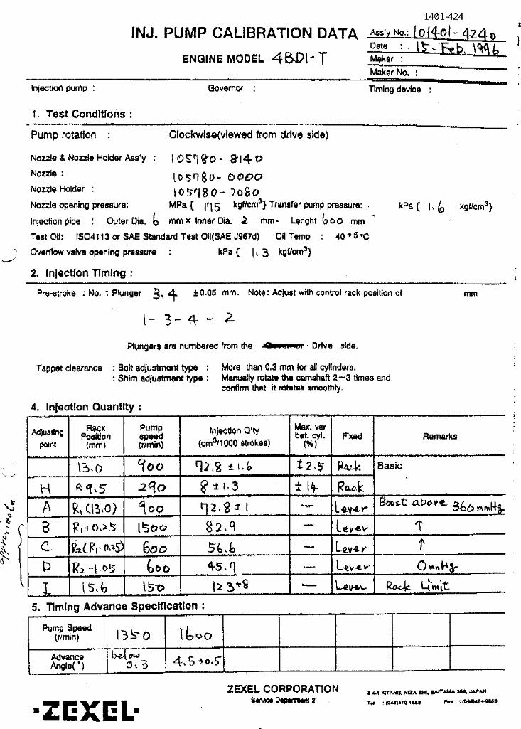

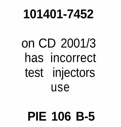
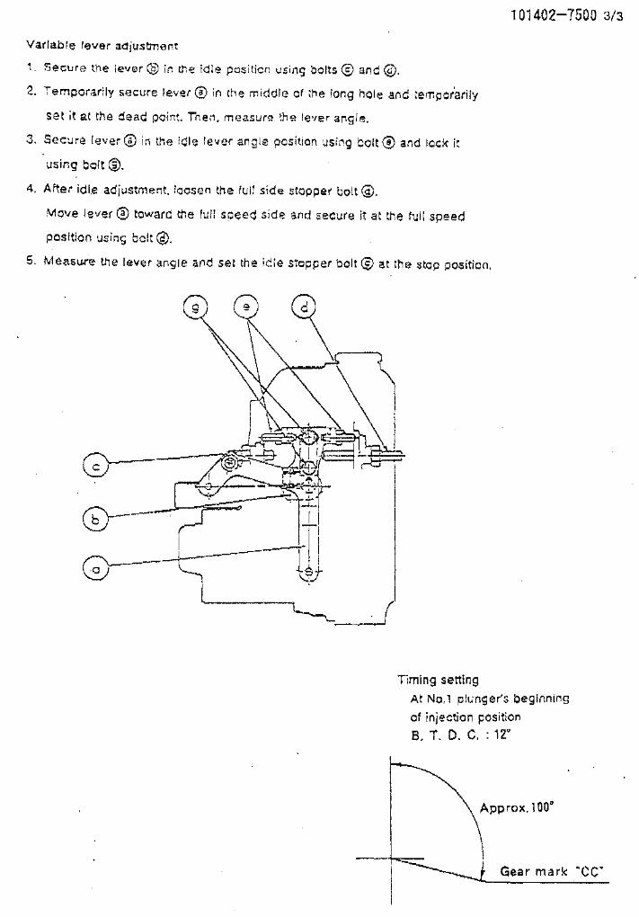
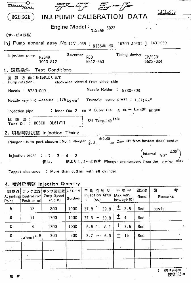
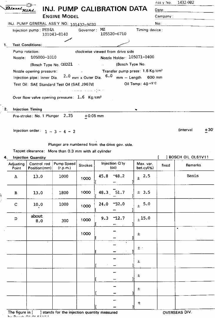
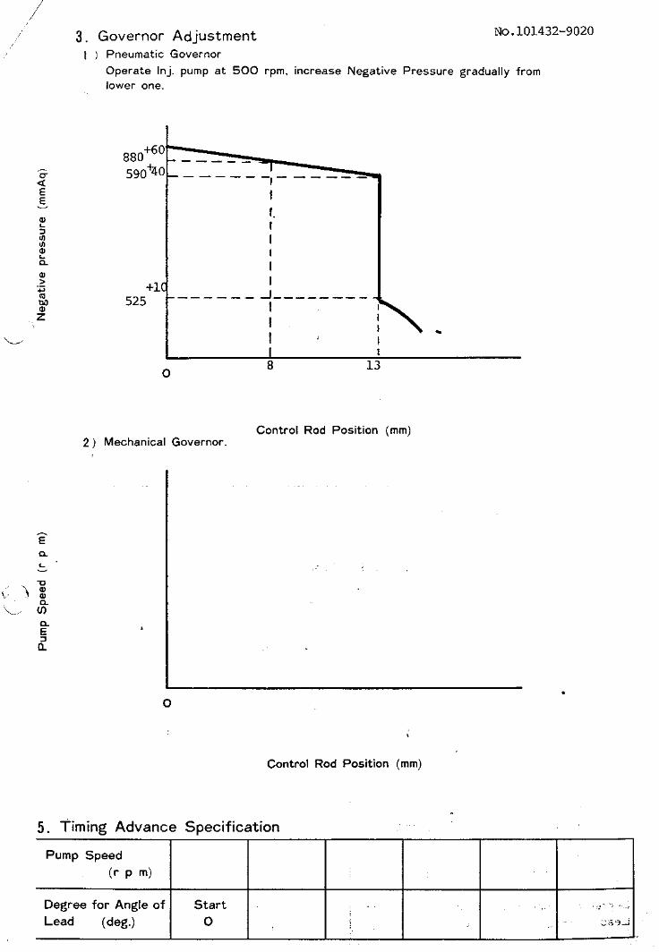
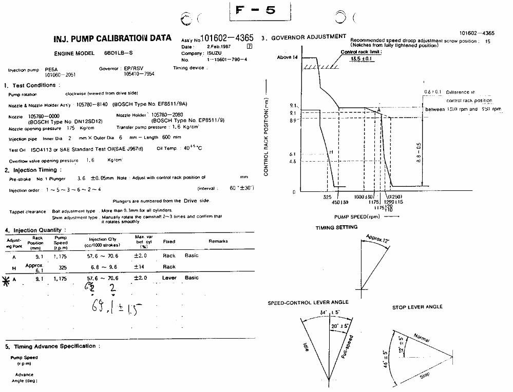
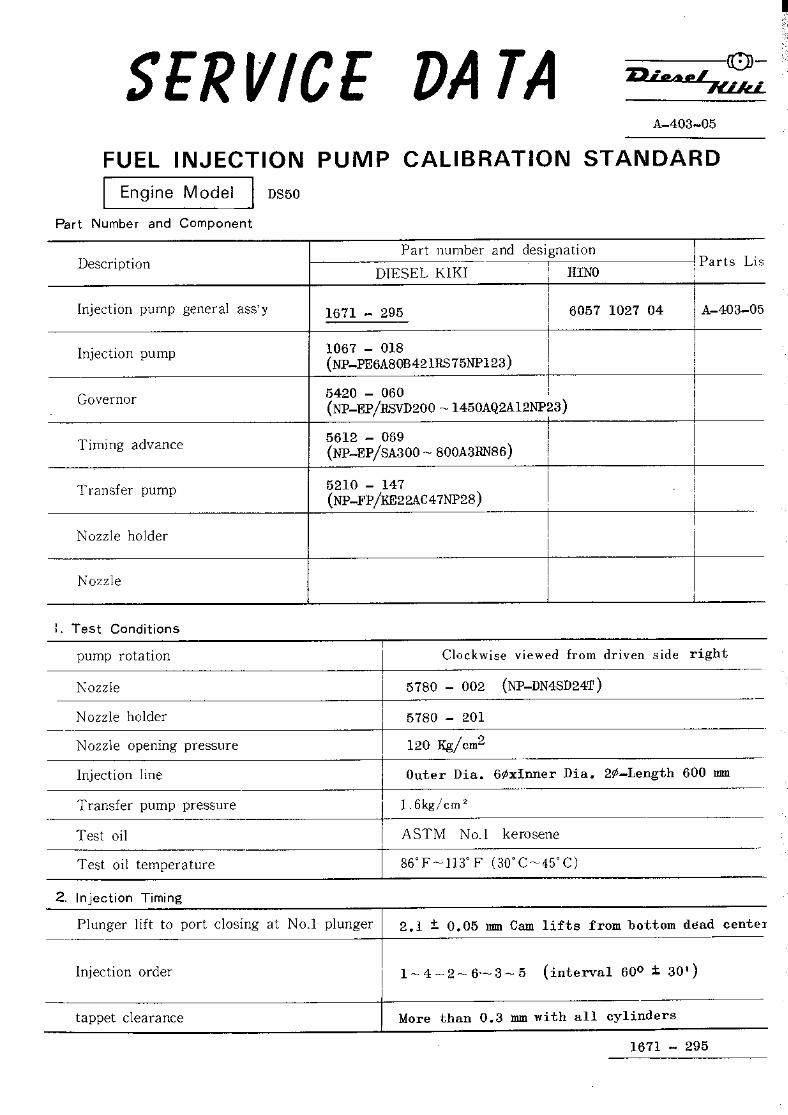
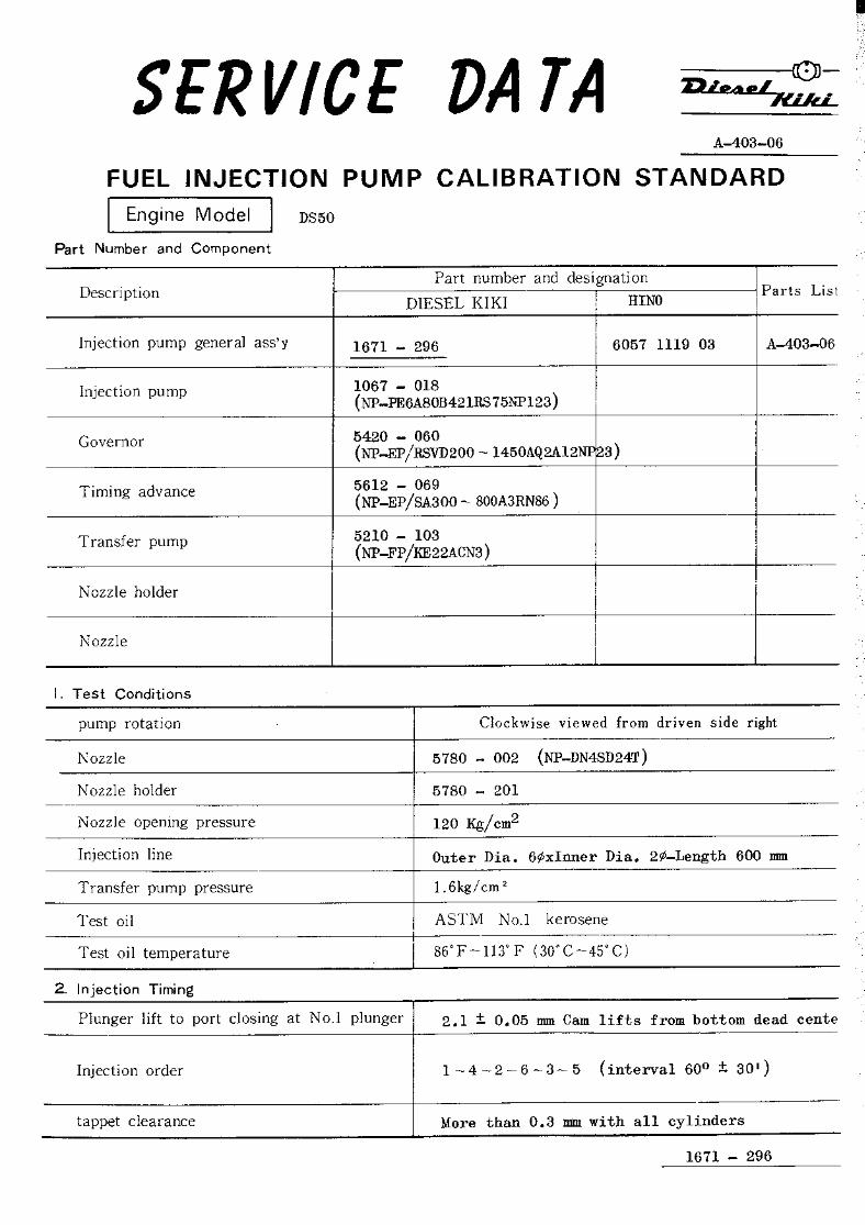
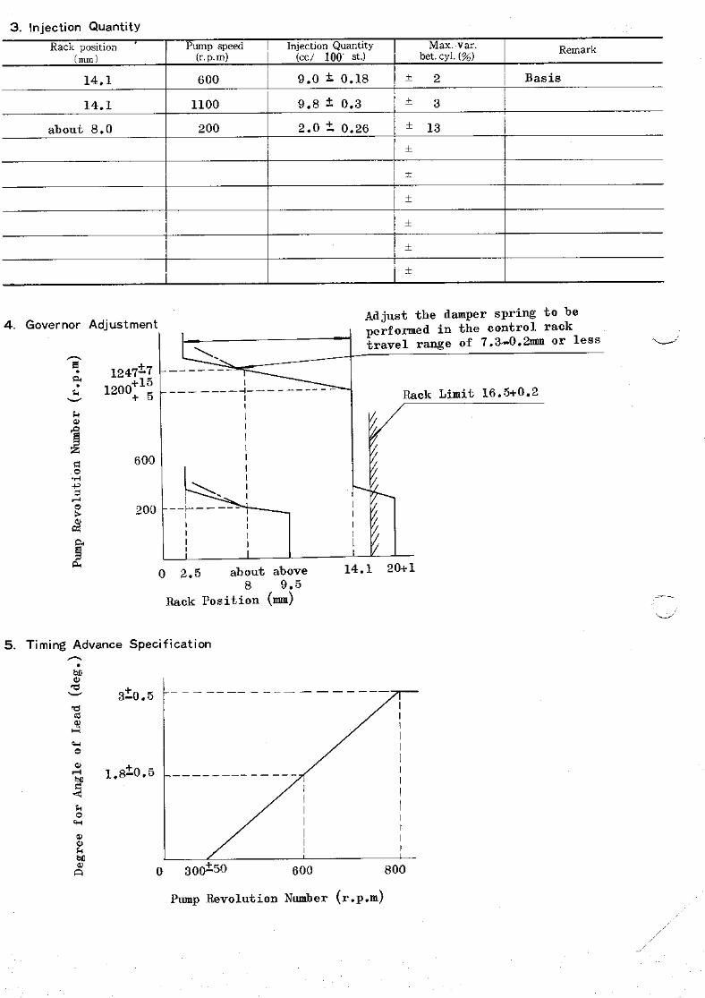
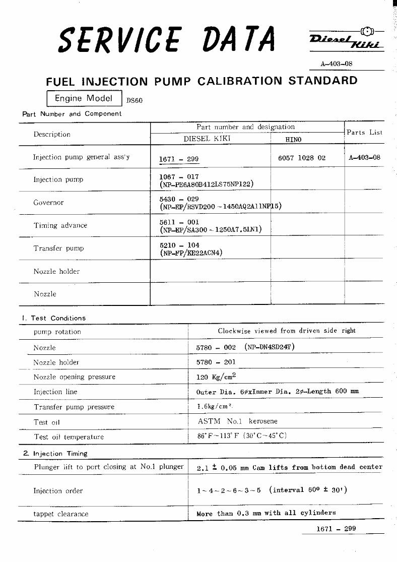
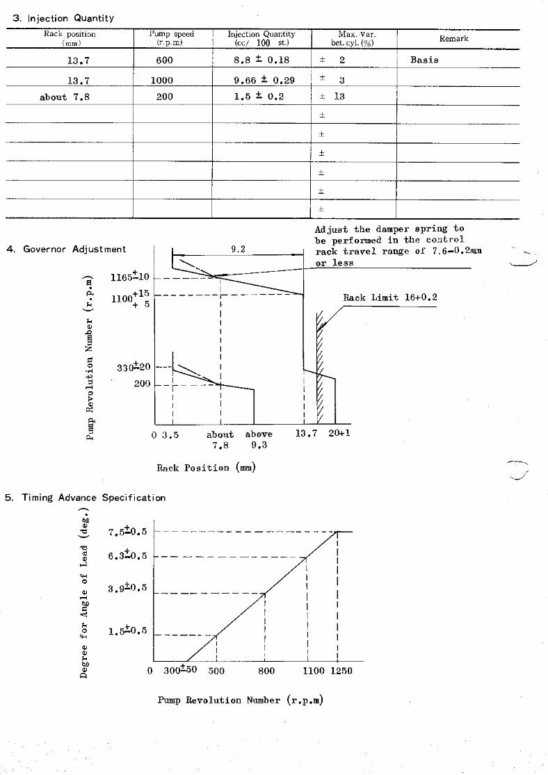
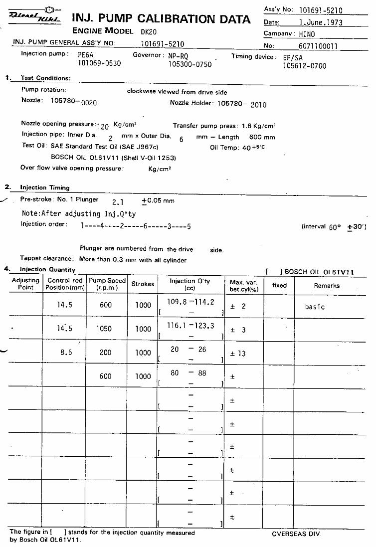
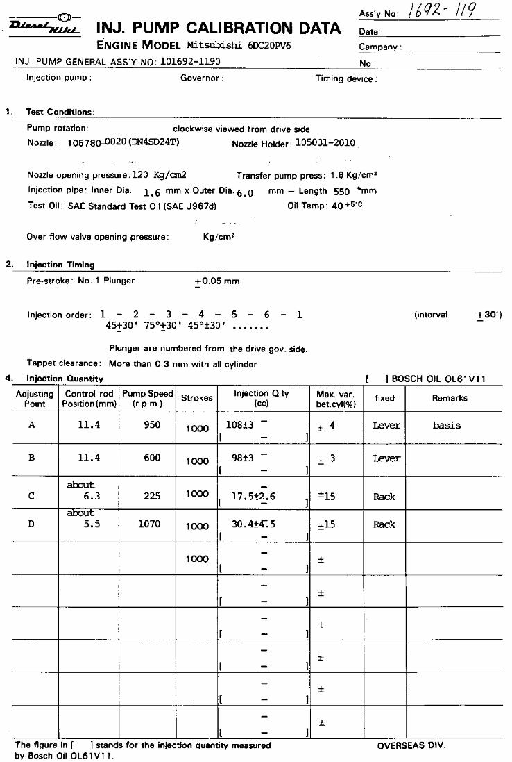
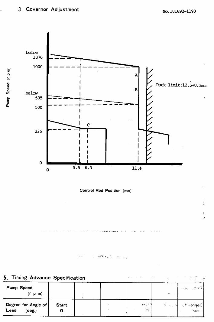
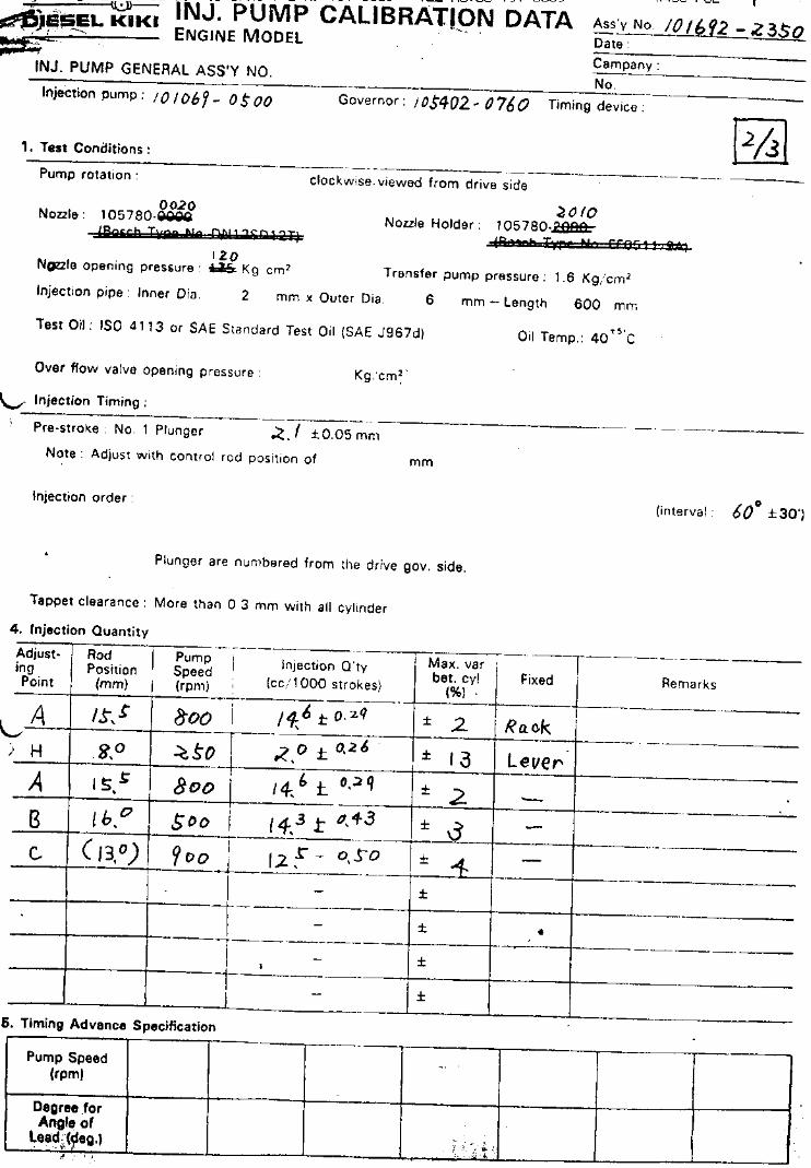
101401-7452
on CD 2001/3has incorrecttest injectors
use
PIE 106 B-5

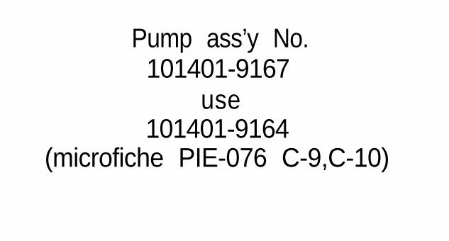
Pump ass’y No.101401-9167
use101401-9164
(microfiche PIE-076 C-9,C-10)
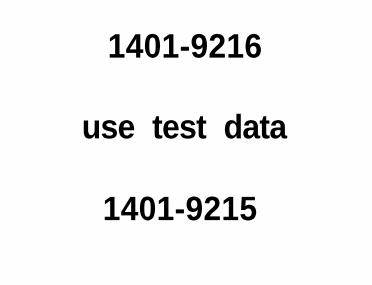
1401-9216
use test data
1401-9215
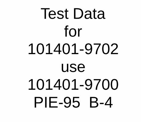
Test Datafor
101401-9702use
101401-9700PIE-95 B-4


Test data1441-9460
use1441-9020


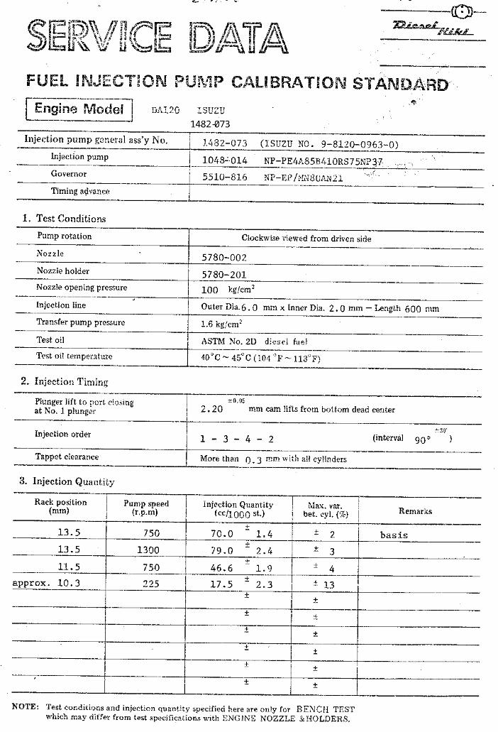
Test data
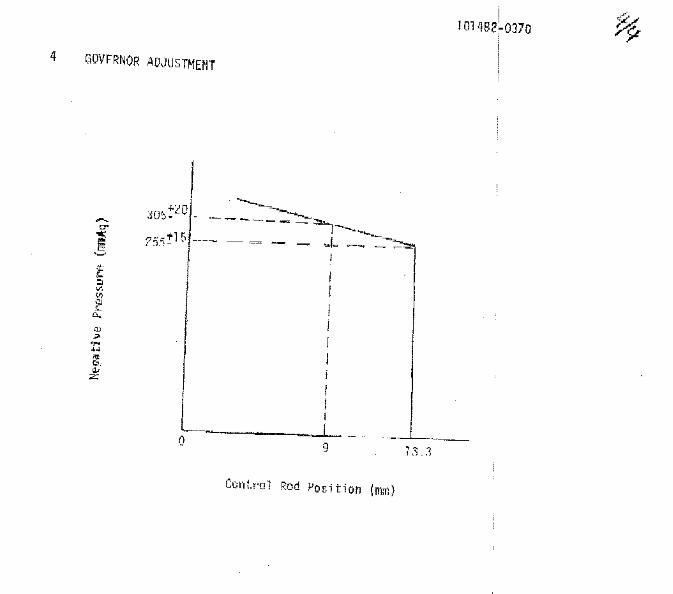
14950350...351...352
use
01491-031


Test data
1601-5061
use
1601-5051


Test data
1603-046
use
1603-886

Test data
1605-9490
use
1605-9081


Test data
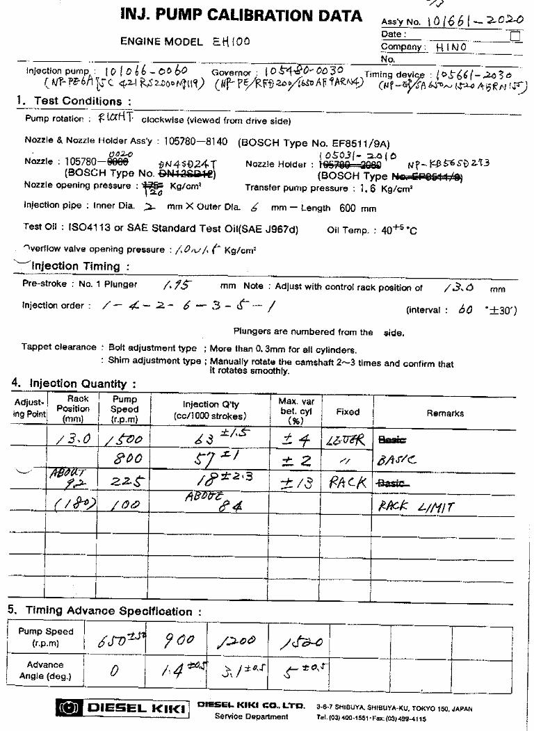
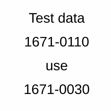
1671-0110
use
1671-0030


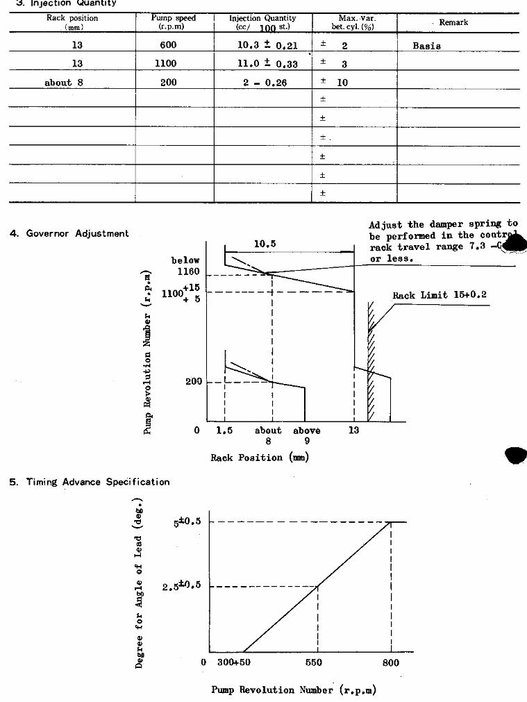
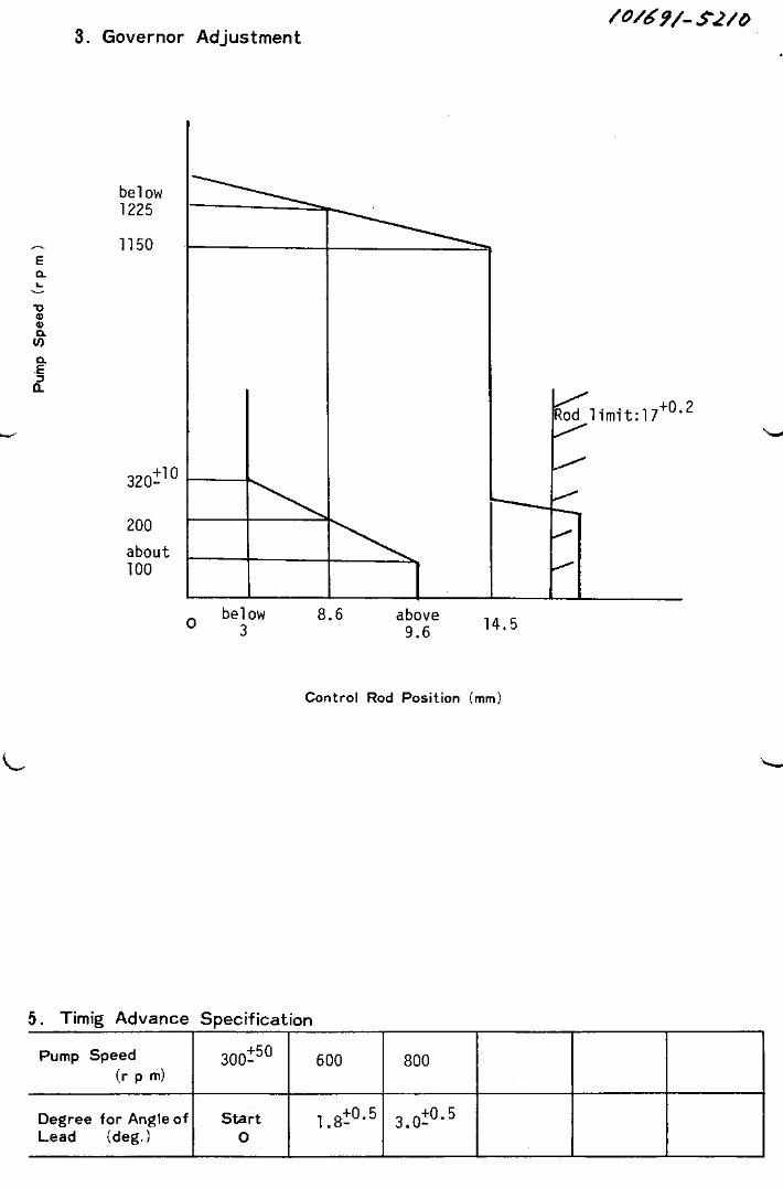
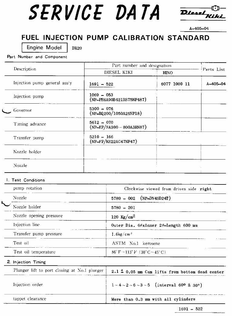
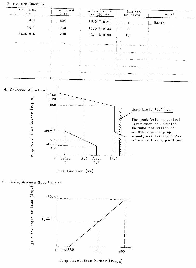
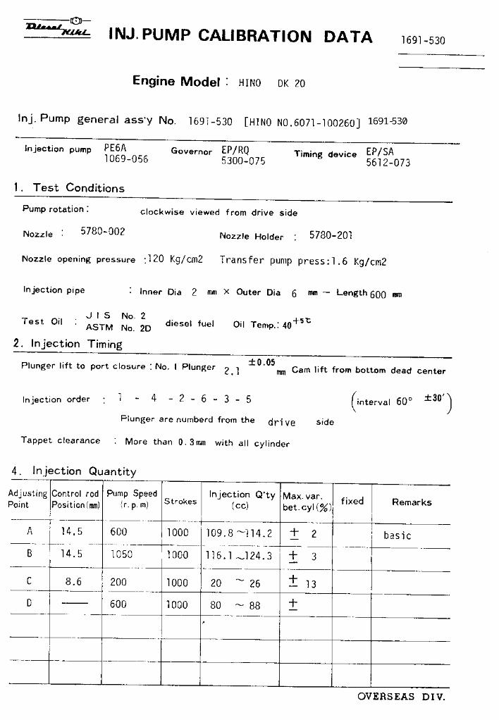
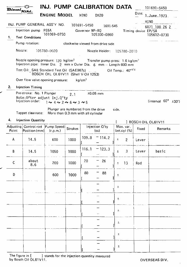
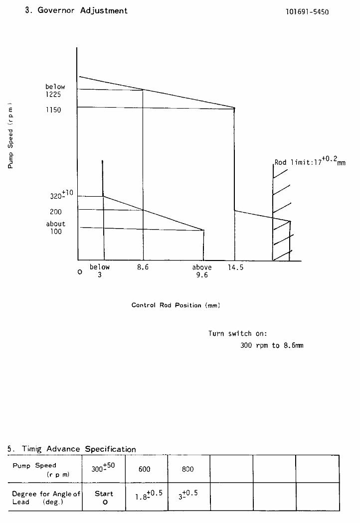
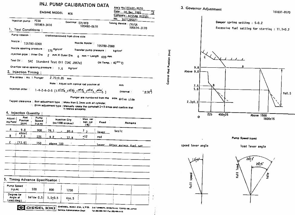
101691-506S/S to 523
No info availablethrough Zexel


Oil temperature: 40+5 °C
BOSCH K.K.Sales Automotive Aftermarket Division
3-4-1 Kitano, Niiza-shi, Saitama-ken, 352-8572, JAPAN
Tel. 81-48-475-2521 Fax. 81-48-475-2520
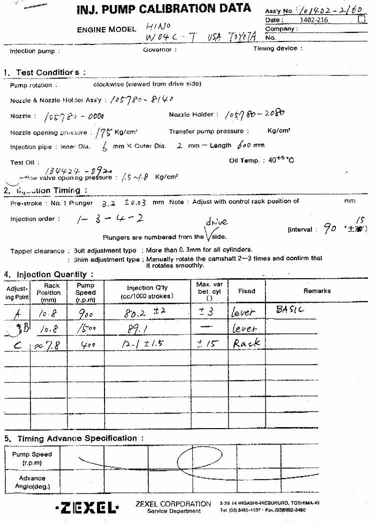
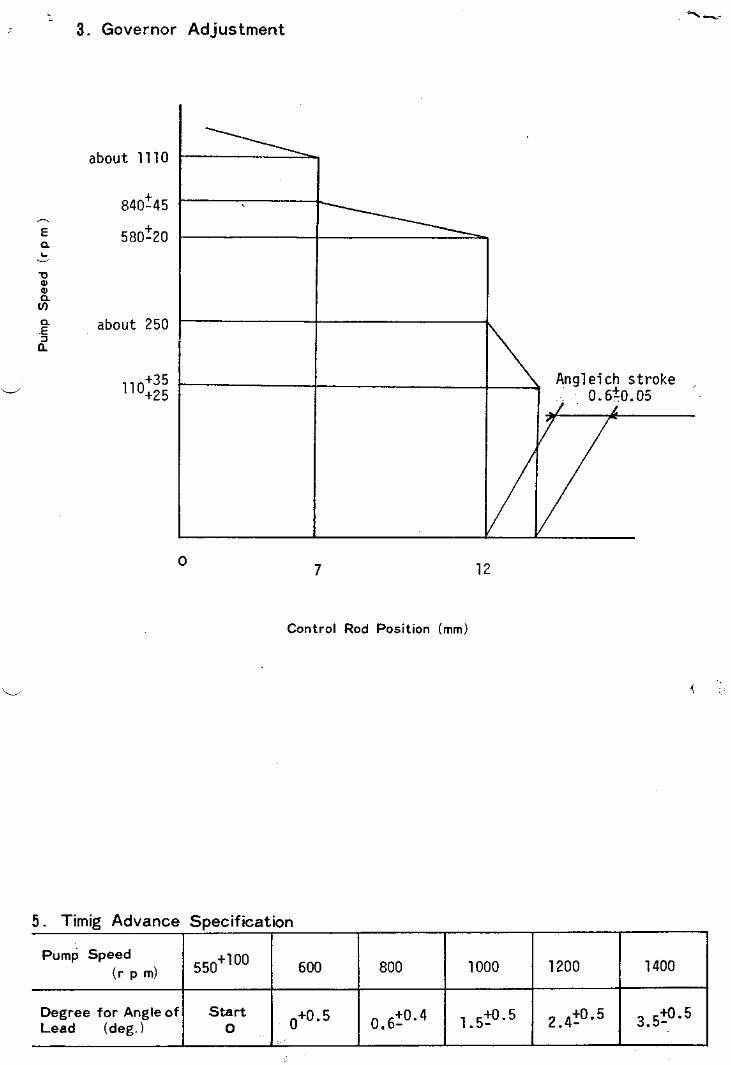
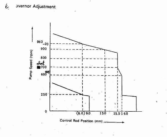
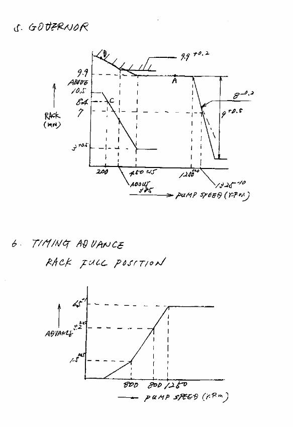
Adjustingpoint
Rackposition
(mm)
Pumpspeed(r/min)
Injection quantity(cm3/1000 strokes)
Max. variationbetween
cylinders (%)Fixed Remarks
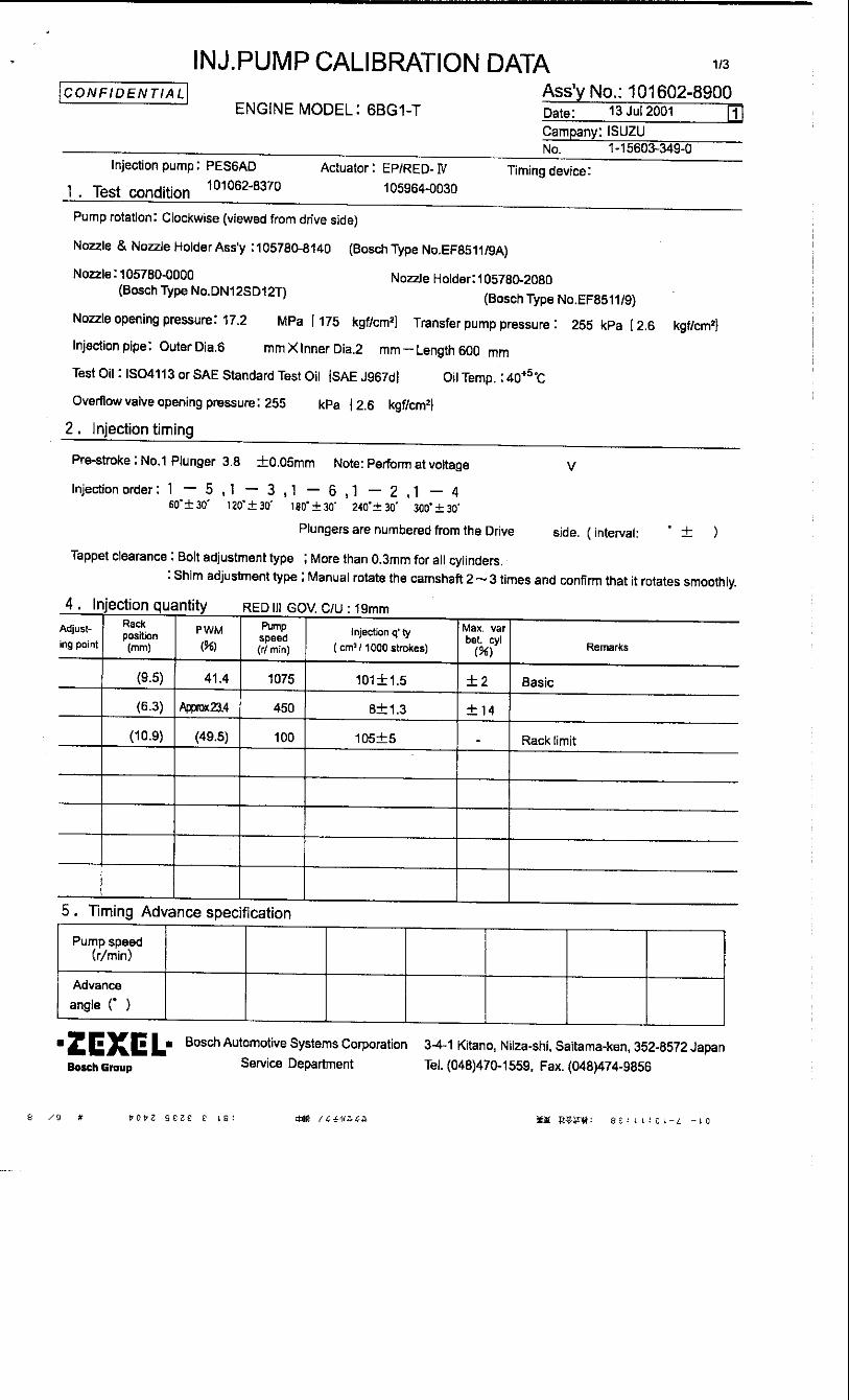
11.9 1310 64.5 ± 1.6 ± 4 Rack
H Approx 9.8 285 15.5 ± 1.3 ± 10 Rack
A R1(11.9) 1310 64.5 ± 1 - Lever
B R1 1600 (67.5) ± 2 - Lever
C R1-0.5 500 (44.7) ± 2 - Lever
E R1-0.05 960 (58.5) ± 2 - Lever
I Above 19.5 150 (80) + 16 - Lever
Injection order: 1 3 , 1 4 , 1 290°± 30' 180°± 30' 270°± 30'
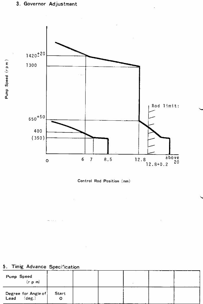
Pump speed(r/min)
(Measure) (Measure)
Advanceangle (° )
Start
0
Finish
5.0±0.5
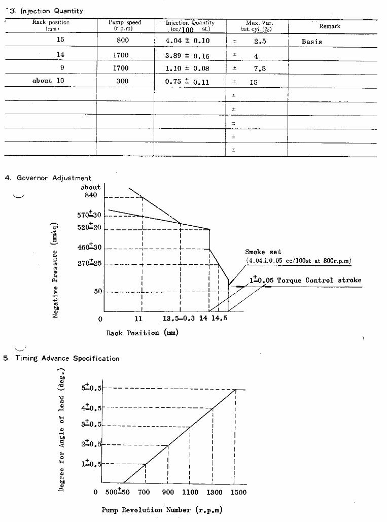
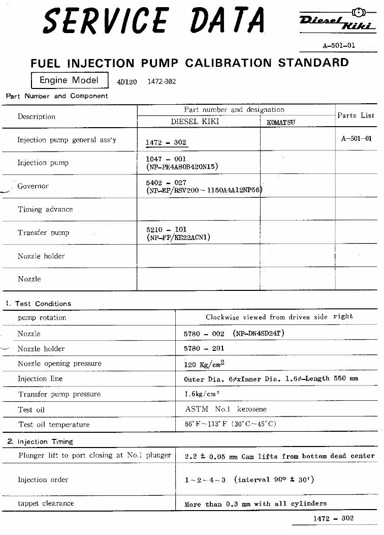
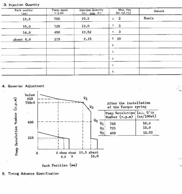
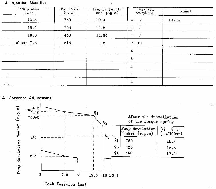
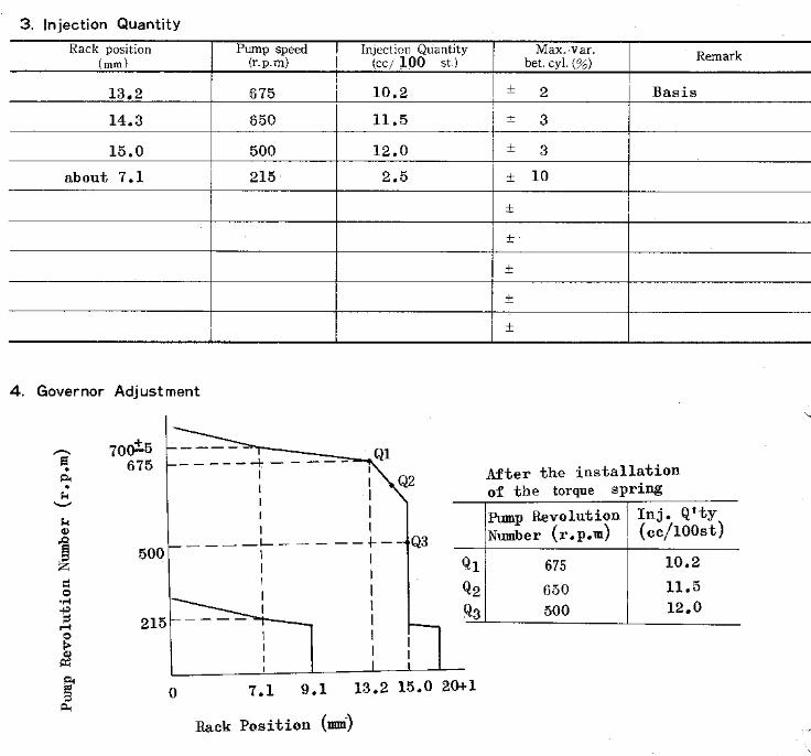
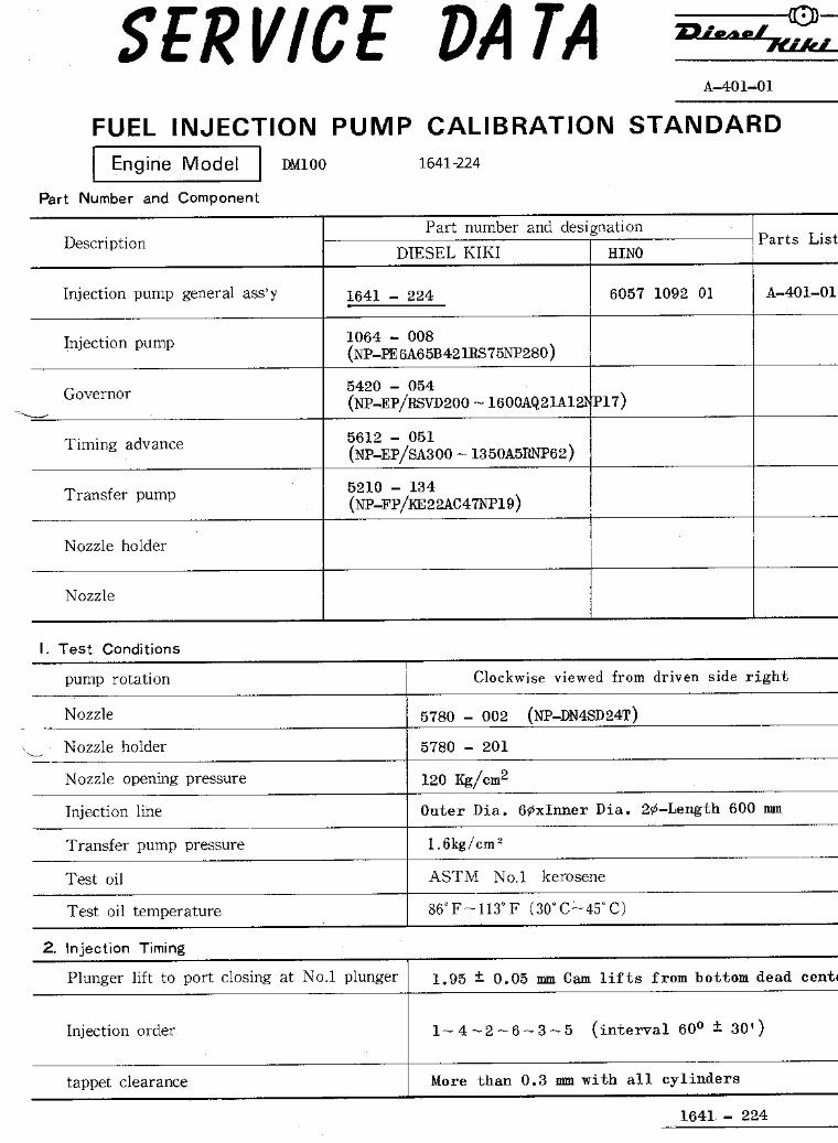
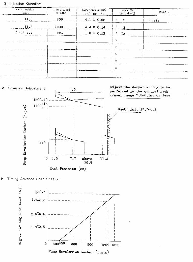
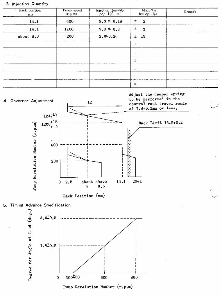
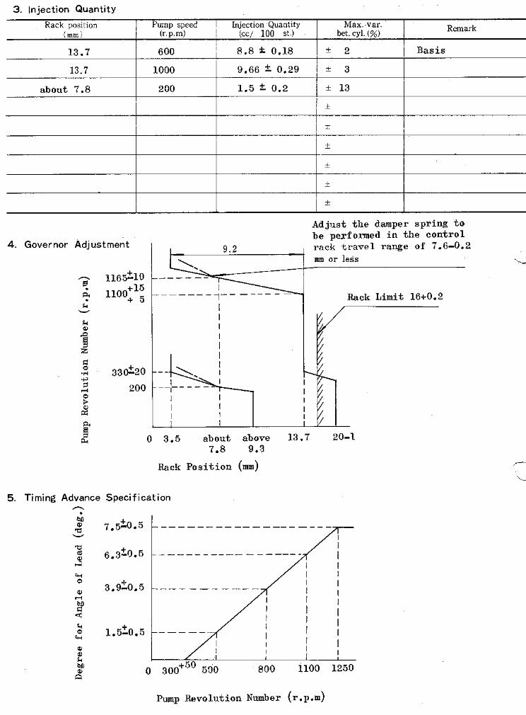
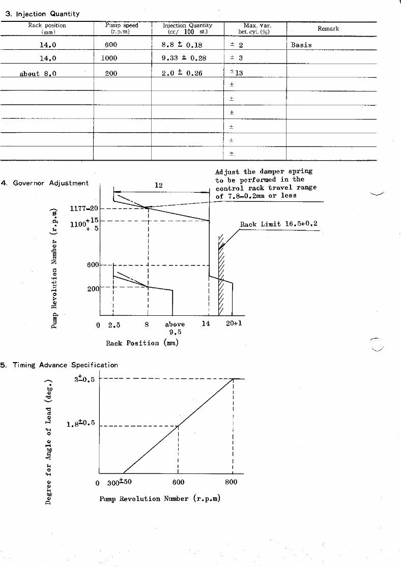
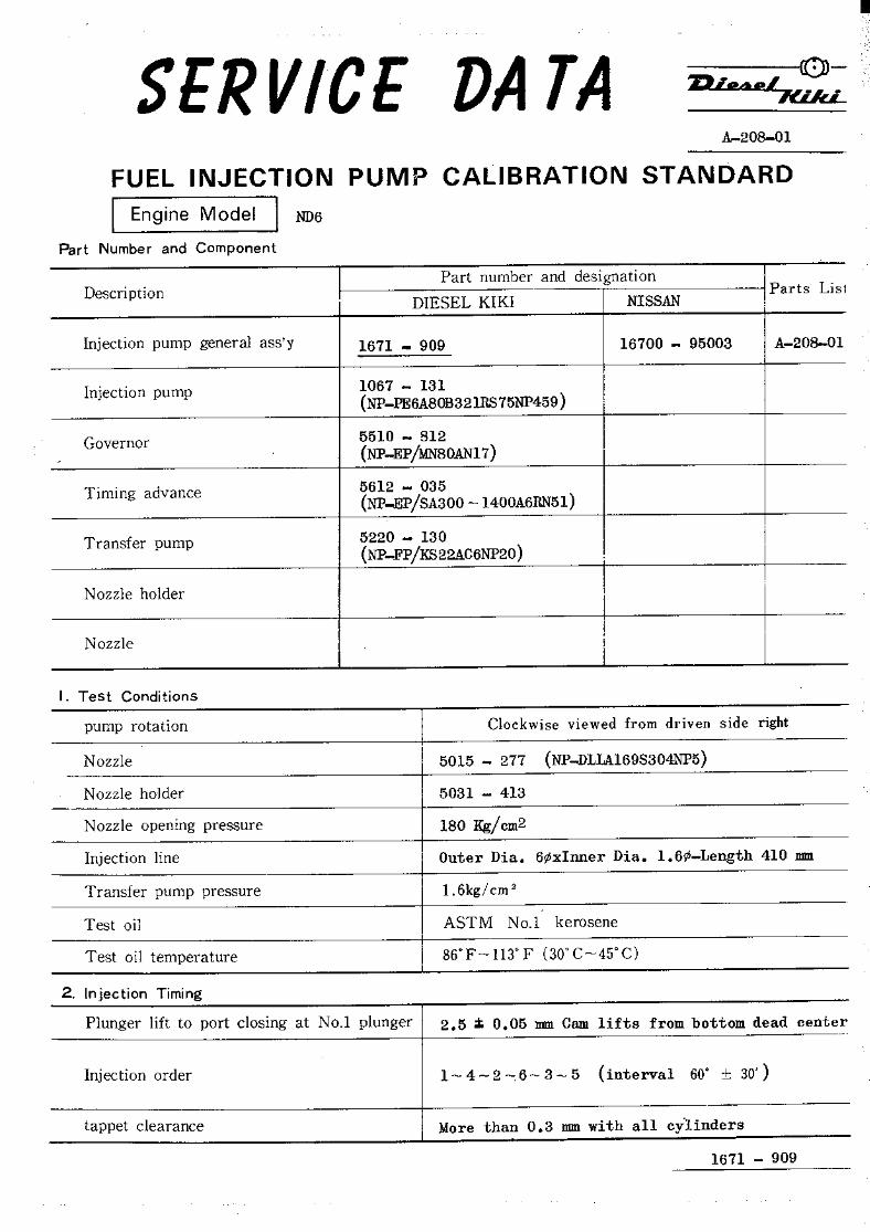
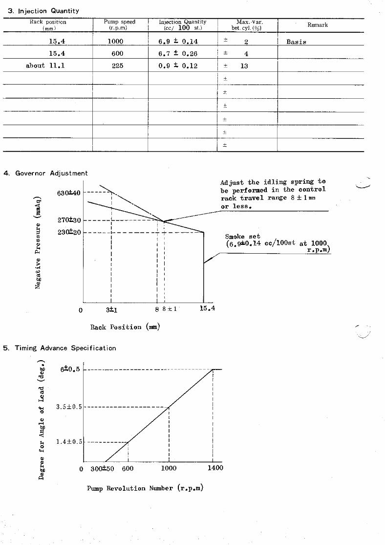
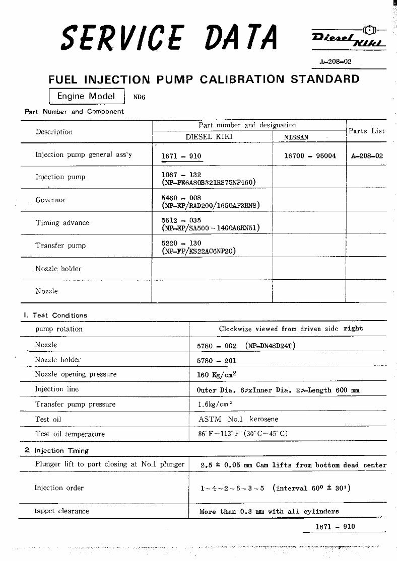
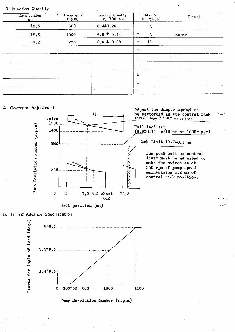
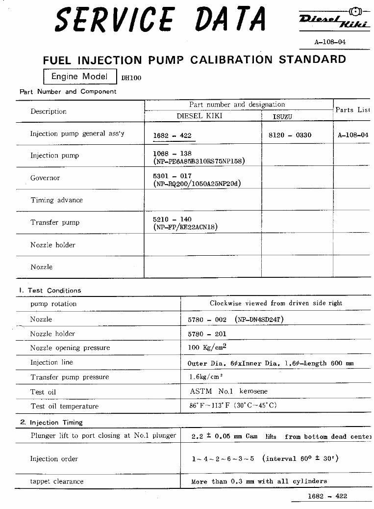
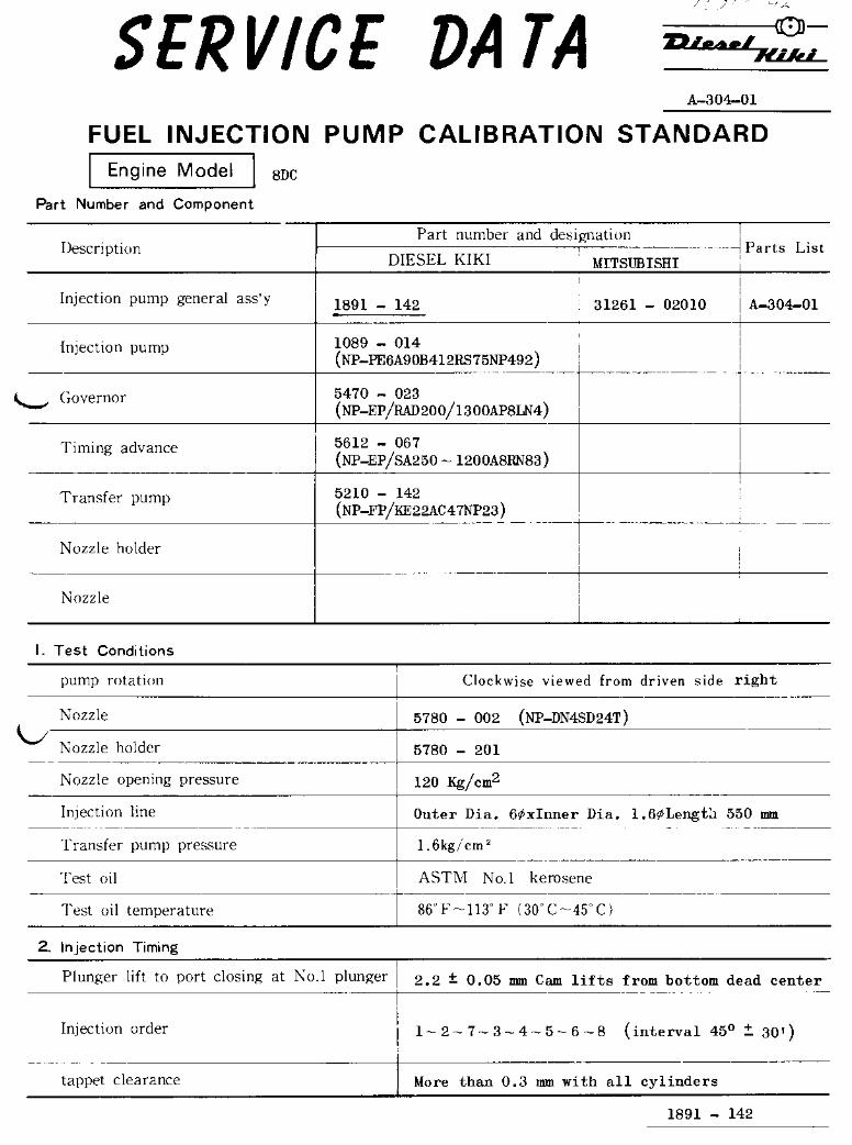
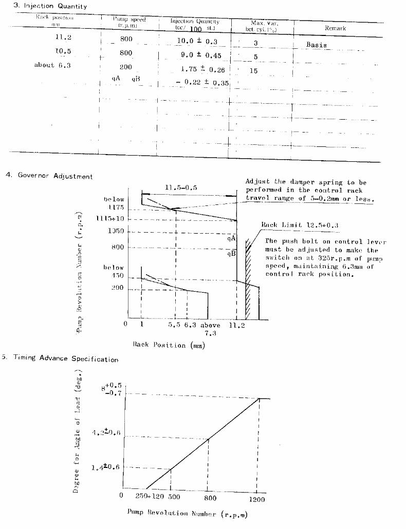
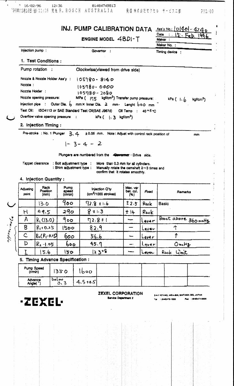
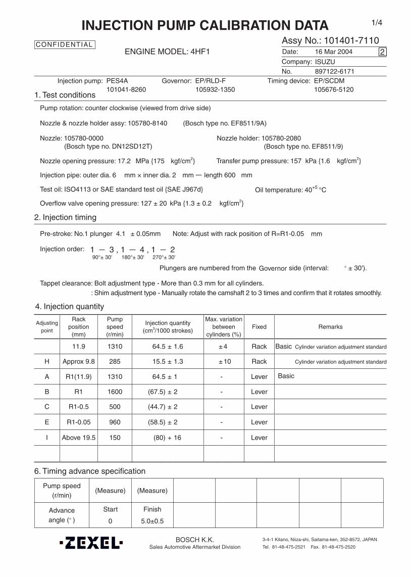
4. Injection quantity
6. Timing advance specification
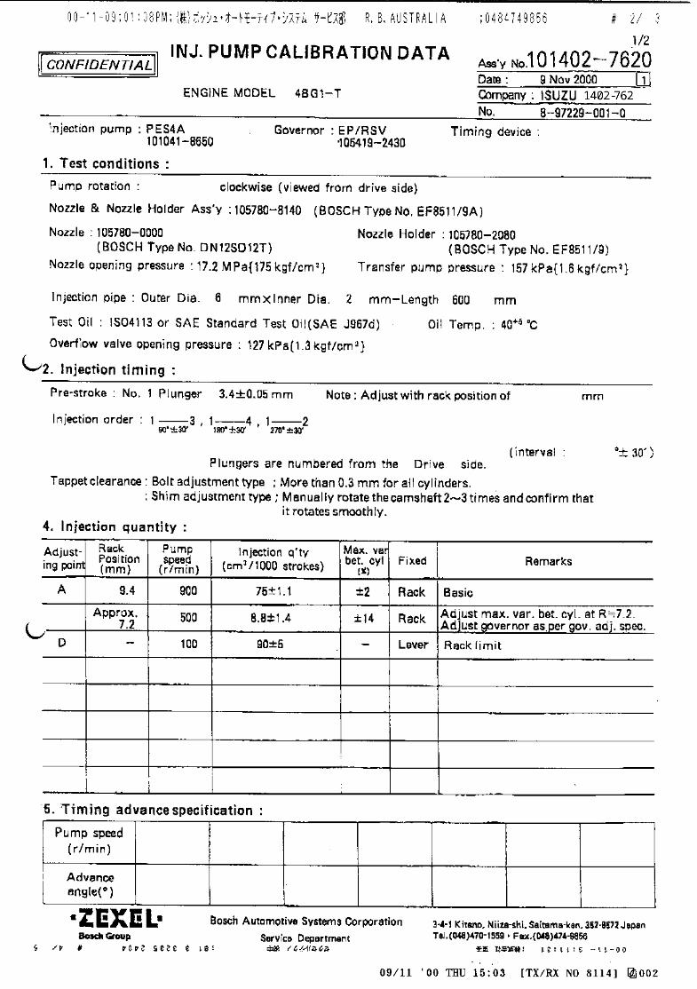
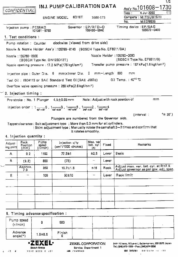
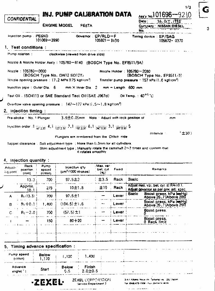
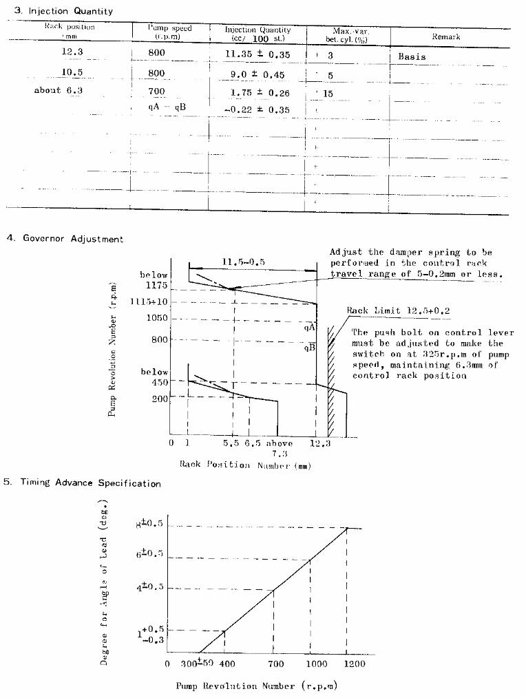
Company:
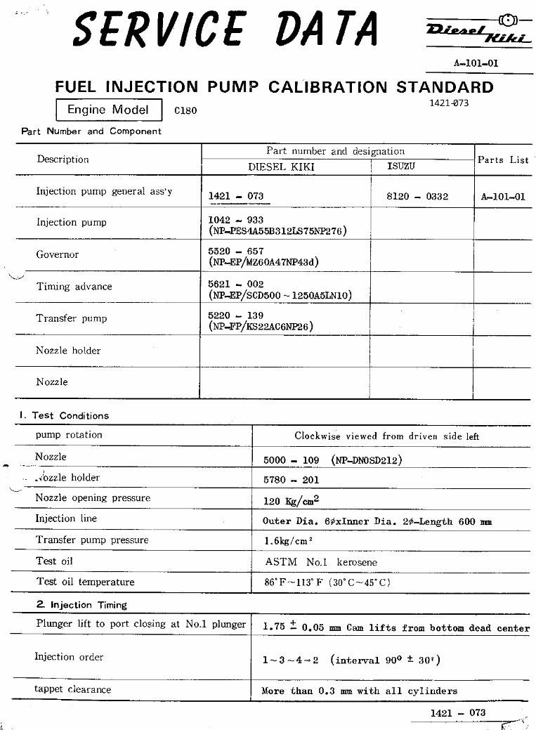
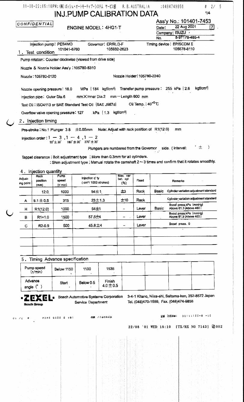
Assy No.: 101401-7110ENGINE MODEL: 4HF1
No. Governor: EP/RLD-F Timing device: EP/SCDM
1. Test conditions
Date:
Pump rotation: counter clockwise (viewed from drive side)
Injection pump: PES4A105932-1350 105676-5120
kgf/cm2}
2. Injection timing
Pre-stroke: No.1 plunger 4.1 ± 0.05mm mm
Plungers are numbered from the ° ± 30').
Tappet clearance: Bolt adjustment type - More than 0.3 mm for all cylinders.: Shim adjustment type - Manually rotate the camshaft 2 to 3 times and confirm that it rotates smoothly.
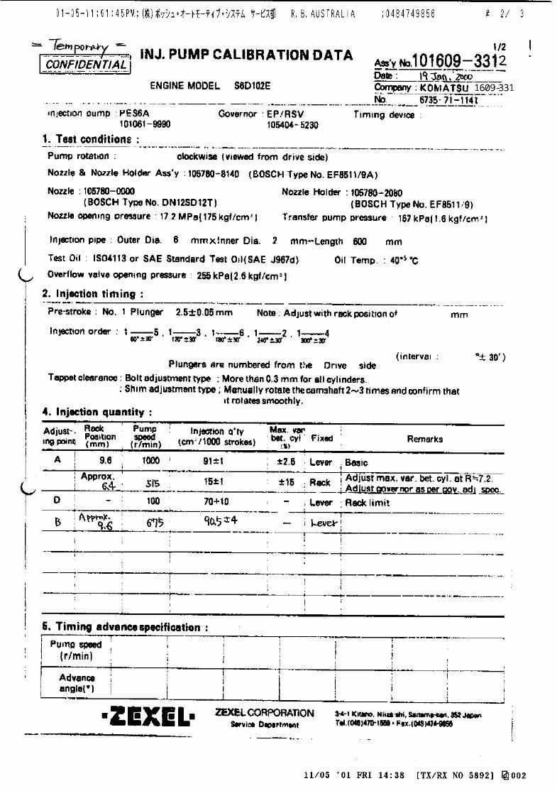
CONFIDENTIAL
INJECTION PUMP CALIBRATION DATA
16 Mar 2004
897122-6171
101041-8260
Injection pipe: outer dia. 6 mm × inner dia. 2 mm length 600 mm
Nozzle opening pressure: 17.2 MPa {175 kgf/cm2}
Nozzle: 105780-0000 Nozzle holder: 105780-2080(Bosch type no. DN12SD12T) (Bosch type no. EF8511/9)
Nozzle & nozzle holder assy: 105780-8140 (Bosch type no. EF8511/9A)
Test oil: ISO4113 or SAE standard test oil {SAE J967d}
side (interval:
2
Transfer pump pressure: 157 kPa {1.6
Note: Adjust with rack position of R=R1-0.05
ISUZU
Governor
1/4
Overflow valve opening pressure: 127 ± 20 kPa {1.3 ± 0.2 kgf/cm2}
Basic Cylinder variation adjustment standard
Basic
Cylinder variation adjustment standard

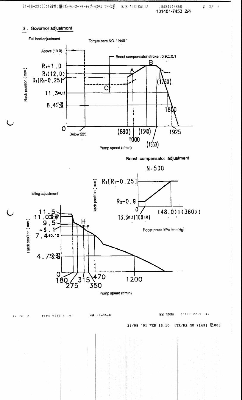
101401-7110 2/4
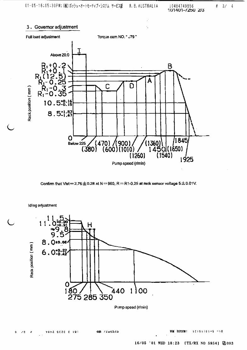
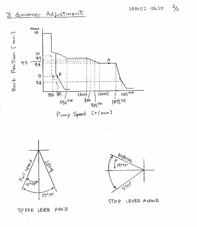
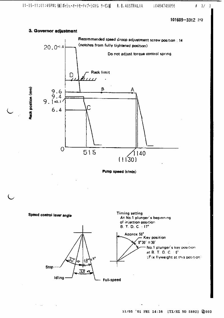
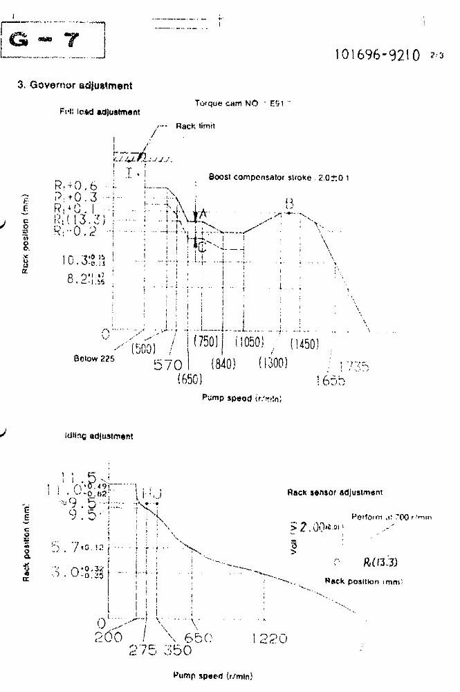
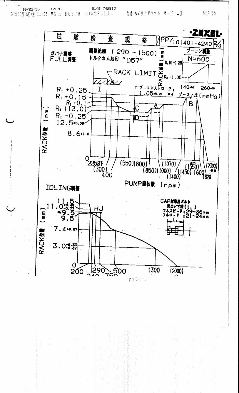
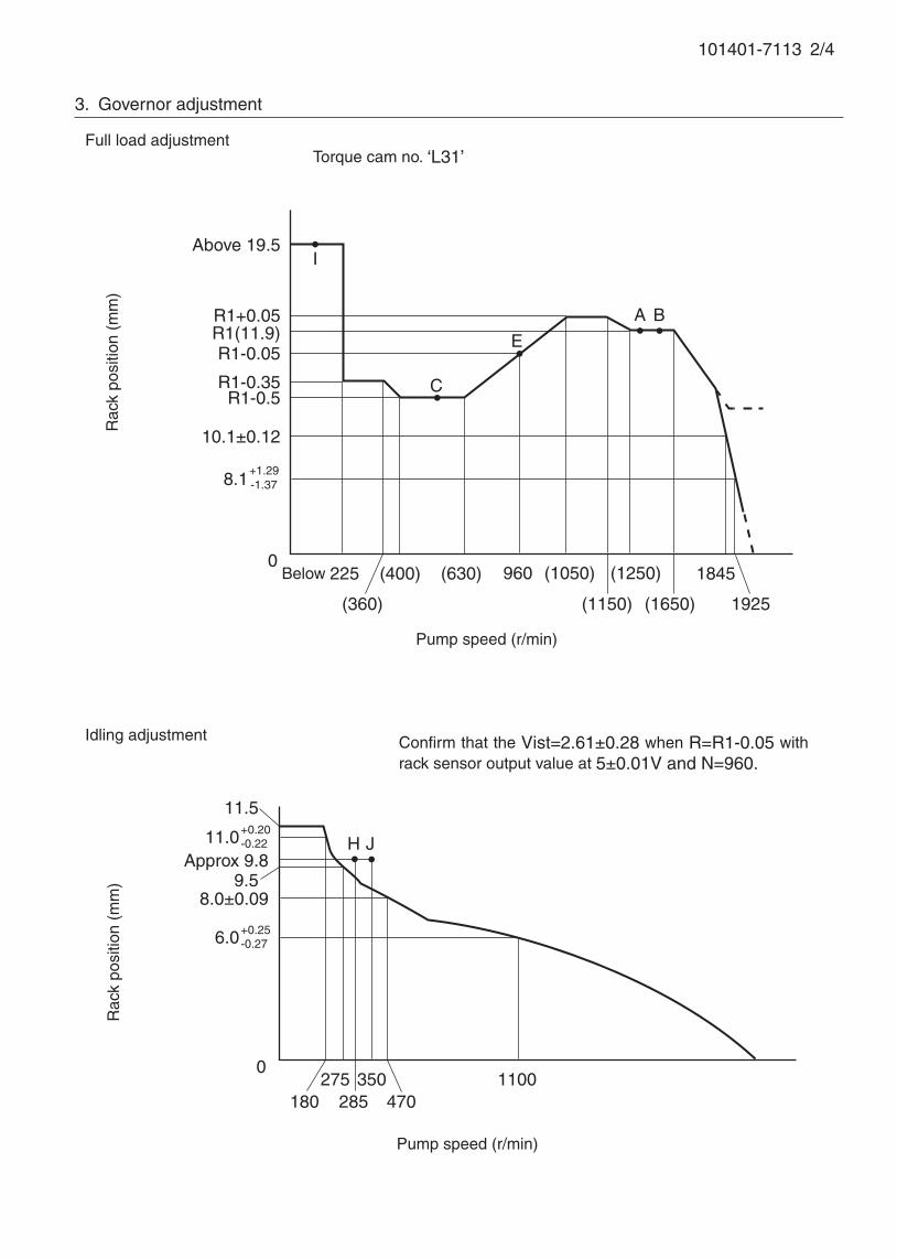
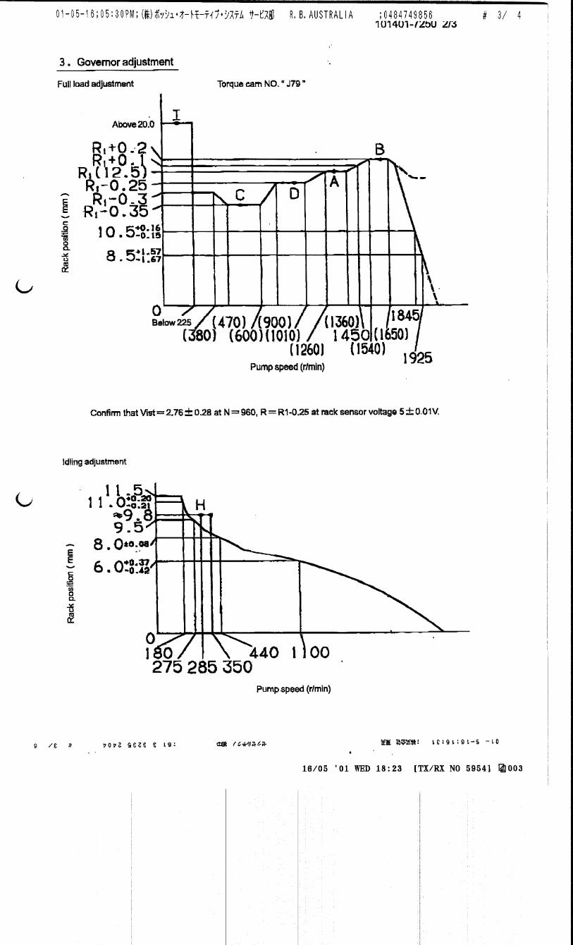
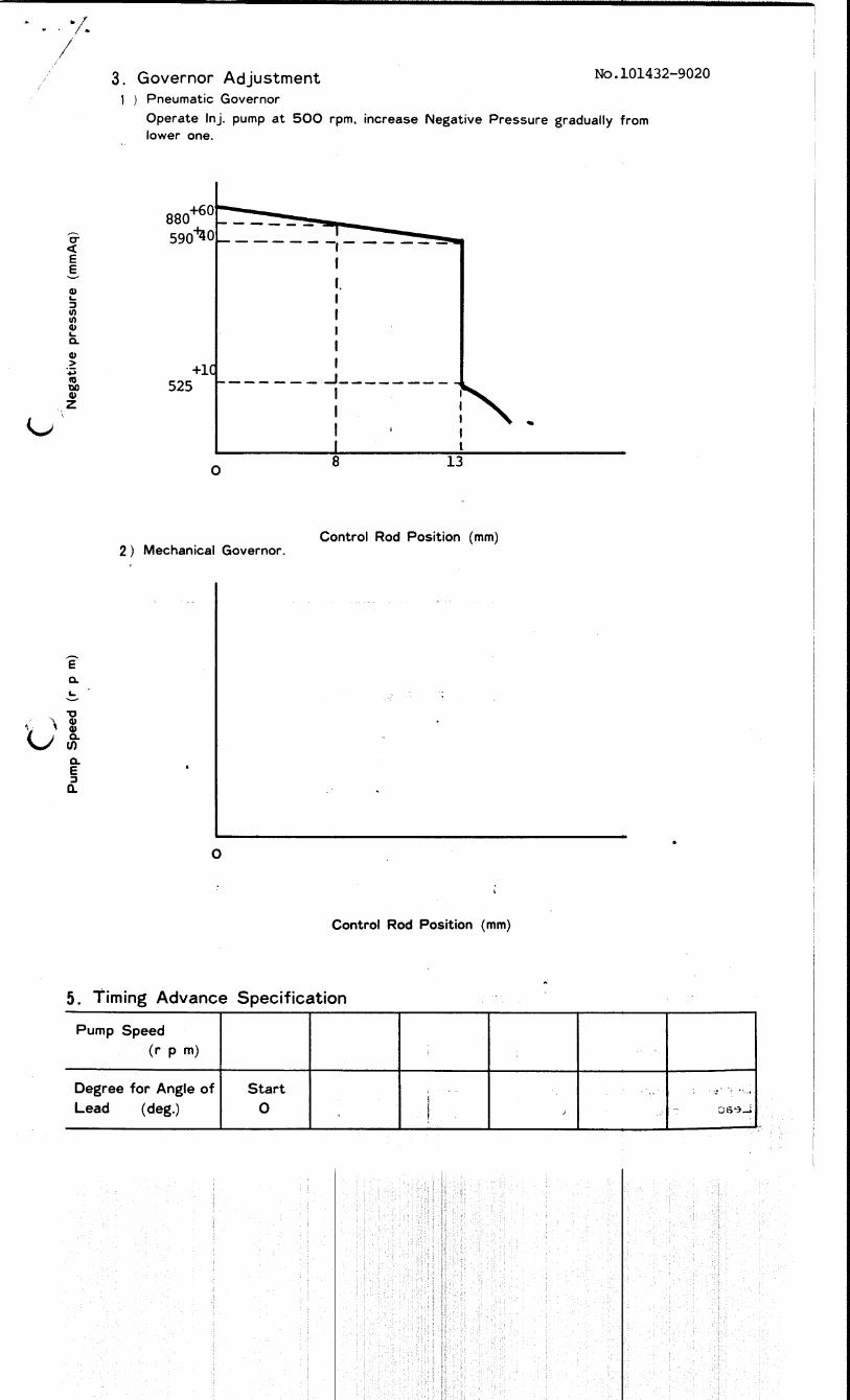
3. Governor adjustment
I
0
180
Rac
k po
sitio
n (m
m)
Pump speed (r/min)
0Below 225 (400) (1250)
A B
Rac
k po
sitio
n (m
m)
Pump speed (r/min)
Torque cam no. ‘L31’
R1+0.05R1(11.9)
(630)
(360)
960
(1650)
1845
8.0±0.09
Approx 9.8
Full load adjustment
Idling adjustment
Above 19.5
9.5
H J
11.5
275285
350 1100
C
R1-0.05
(1150)
11.0+0.20-0.22
E
10.1±0.12
R1-0.35R1-0.5
+1.29-1.378.1
(1050)
1925
6.0+0.25-0.27
470
Confirm that the Vist=2.61±0.28 when R=R1-0.05 with rack sensor output value at 5±0.01V and N=960.

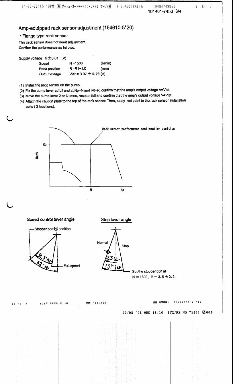
101401-7110 3/4
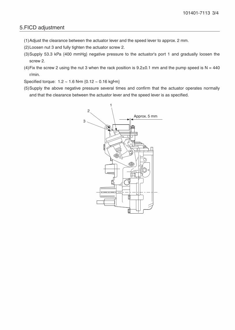
5.FICD adjustment
(1) Adjust the clearance between the actuator lever and the speed lever to approx. 2 mm.
(2) Loosen nut 3 and fully tighten the actuator screw 2.
(3) Supply 53.3 kPa {400 mmHg} negative pressure to the actuator's port 1 and gradually loosen the
screw 2.
(4) Fix the screw 2 using the nut 3 when the rack position is 9.2±0.1 mm and the pump speed is N = 440
r/min.
Specified torque: 1.2 ~ 1.6 N•m {0.12 ~ 0.16 kgf•m}
(5) Supply the above negative pressure several times and confirm that the actuator operates normally
and that the clearance between the actuator lever and the speed lever is as specified.
Approx. 5 mm
1
2
3

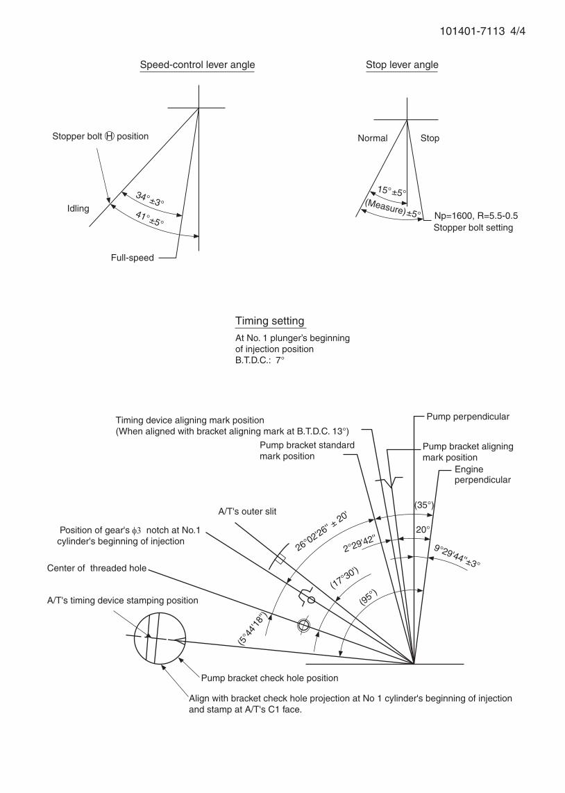
101401-7110 4/4
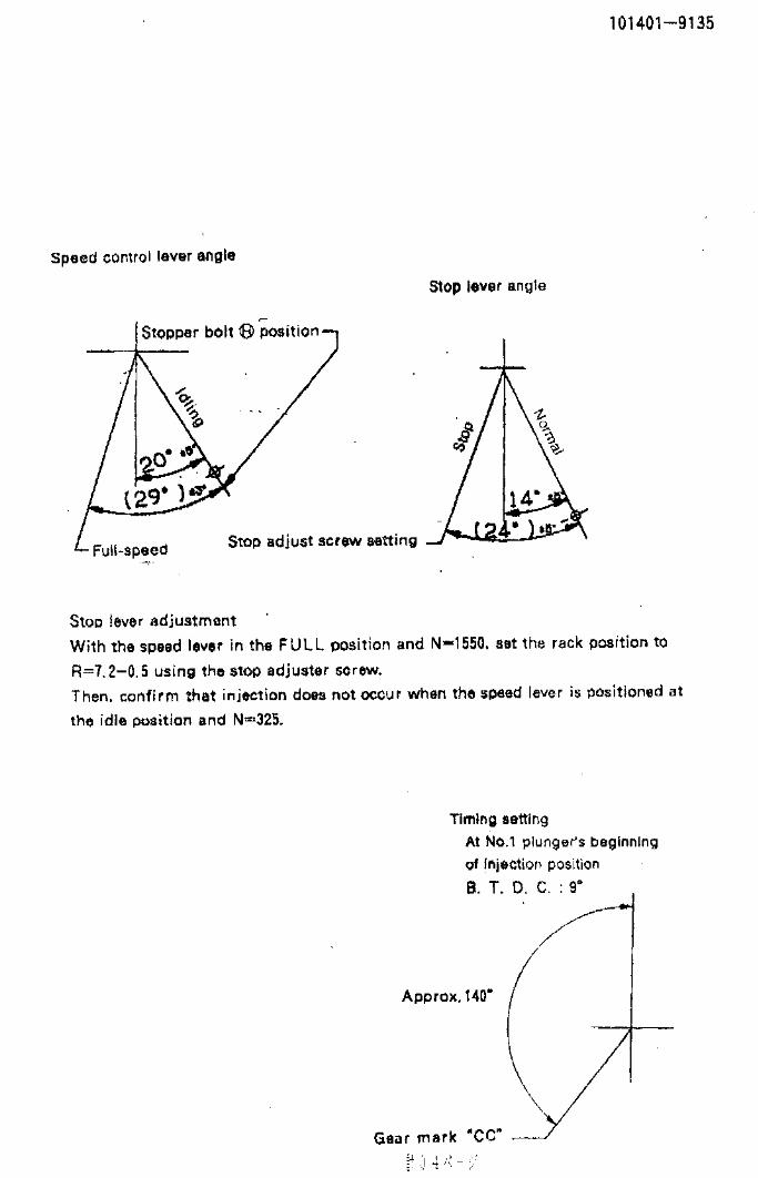
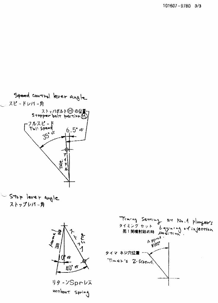
Stopper bolt setting
Stop lever angle
(35°)
Timing setting
At No. 1 plunger’s beginning of injection positionB.T.D.C.: 7°
Position of gear's 3 notch at No.1 cylinder's beginning of injection
Stopper bolt H position
Np=1600, R=5.5-0.5
Stop Normal
34°±3° (Measure)±5°
15°±5°
Speed-control lever angle
Idling 41°±5°
Center of threaded hole
(5°4
4'18''
)
26°36'38'' ± 20'
3°
20°
10°03'56''±3°
(17°30')
(95°)
Timing device aligning mark position(When aligned with bracket aligning mark at B.T.D.C. 13°)
Engine perpendicular
Pump perpendicular
Pump bracket aligning mark position
Pump bracket standard mark position
Align with bracket check hole projection at No 1 cylinder's beginning of injection and stamp at A/T's C1 face.
A/T's timing device stamping position
A/T's outer slit
Pump bracket check hole position
Full-speed

Oil temperature: 40+5 °C
BOSCH K.K.Sales Automotive Aftermarket Division
3-4-1 Kitano, Niiza-shi, Saitama-ken, 352-8572, JAPAN
Tel. 81-48-475-2521 Fax. 81-48-475-2520
Adjustingpoint
Rackposition
(mm)
Pumpspeed(r/min)
Injection quantity(cm3/1000 strokes)
Max. variationbetween
cylinders (%)Fixed Remarks
11.9 1310 64.5 ± 1.6 ± 4 Rack
H Approx 9.8 285 15.5 ± 1.3 ± 10 Rack
A R1(11.9) 1310 64.5 ± 1 - Lever
B R1 1600 (67.5) ± 2 - Lever
C R1-0.5 500 (44.7) ± 2 - Lever
E R1-0.05 960 (58.5) ± 2 - Lever
I Above 19.5 150 (80) + 16 - Lever
Injection order: 1 3 , 1 4 , 1 290°± 30' 180°± 30' 270°± 30'
Pump speed(r/min)
(Measure) (Measure)
Advanceangle (° )
Start
0
Finish
5.0±0.5
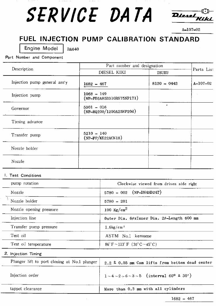
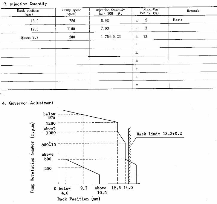
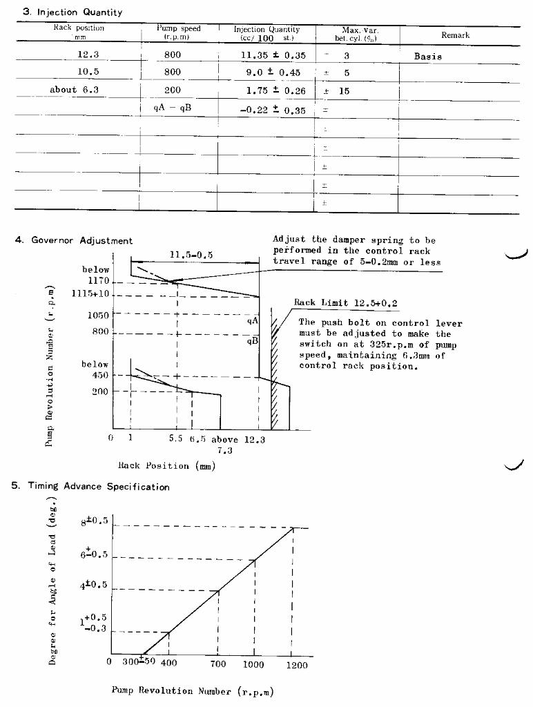
4. Injection quantity
6. Timing advance specification
Company:
Assy No.: 101401-7113ENGINE MODEL: 4HF1
No. Governor: EP/RLD-F Timing device: EP/SCDM
1. Test conditions
Date:
Pump rotation: counter clockwise (viewed from drive side)
Injection pump: PES4A105932-1352 105676-5121
kgf/cm2}
2. Injection timing
Pre-stroke: No.1 plunger 4.1 ± 0.05mm mm
Plungers are numbered from the ° ± 30').
Tappet clearance: Bolt adjustment type - More than 0.3 mm for all cylinders.: Shim adjustment type - Manually rotate the camshaft 2 to 3 times and confirm that it rotates smoothly.
CONFIDENTIAL
INJECTION PUMP CALIBRATION DATA
29 Jan 2004
897146-7880
101041-8510
Injection pipe: outer dia. 6 mm × inner dia. 2 mm length 600 mm
Nozzle opening pressure: 17.2 MPa {175 kgf/cm2}
Nozzle: 105780-0000 Nozzle holder: 105780-2080(Bosch type no. DN12SD12T) (Bosch type no. EF8511/9)
Nozzle & nozzle holder assy: 105780-8140 (Bosch type no. EF8511/9A)
Test oil: ISO4113 or SAE standard test oil {SAE J967d}
side (interval:
3
Transfer pump pressure: 157 kPa {1.6
Note: Adjust with rack position of R=R1-0.05
ISUZU
Governor
1/4
Overflow valve opening pressure: 127 ± 20 kPa {1.3 ± 0.2 kgf/cm2}
Cylinder variation adjustment standard
Basic Cylinder variation adjustment standard
Basic
101401-7113 2/4
3. Governor adjustment
I
0
180
Rac
k po
sitio
n (m
m)
Pump speed (r/min)
0Below 225 (400) (1250)
A B
Rac
k po
sitio
n (m
m)
Pump speed (r/min)
Torque cam no. ‘L31’
R1+0.05R1(11.9)
(630)
(360)
960
(1650)
1845
8.0±0.09
Approx 9.8
Full load adjustment
Idling adjustment
Above 19.5
9.5
H J
11.5
275285
350 1100
C
R1-0.05
(1150)
11.0+0.20-0.22
E
10.1±0.12
R1-0.35R1-0.5
+1.29-1.378.1
(1050)
1925
6.0+0.25-0.27
470
Confirm that the Vist=2.61±0.28 when R=R1-0.05 with rack sensor output value at 5±0.01V and N=960.
101401-7113 3/4
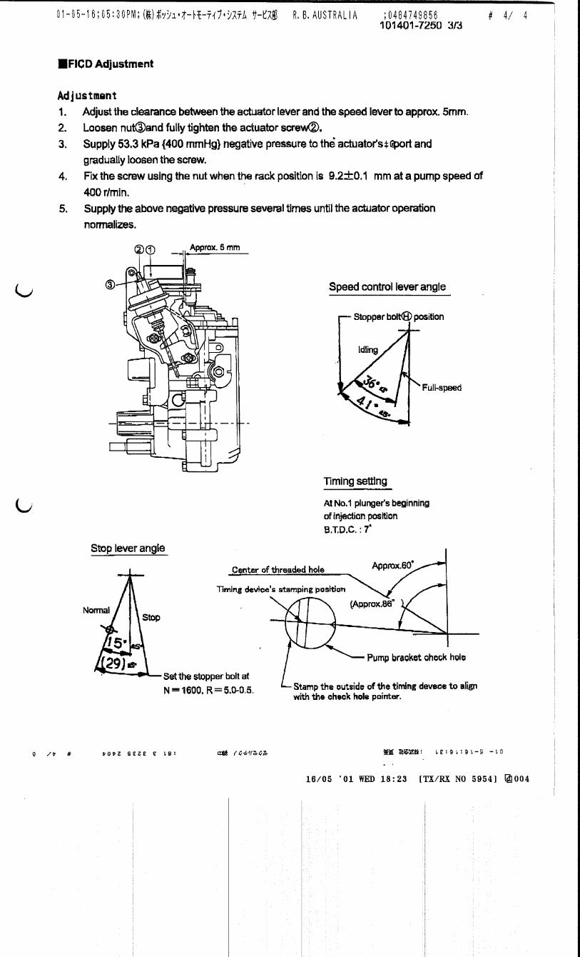
5.FICD adjustment
(1) Adjust the clearance between the actuator lever and the speed lever to approx. 2 mm.
(2) Loosen nut 3 and fully tighten the actuator screw 2.
(3) Supply 53.3 kPa {400 mmHg} negative pressure to the actuator's port 1 and gradually loosen the
screw 2.
(4) Fix the screw 2 using the nut 3 when the rack position is 9.2±0.1 mm and the pump speed is N = 440
r/min.
Specified torque: 1.2 ~ 1.6 N•m {0.12 ~ 0.16 kgf•m}
(5) Supply the above negative pressure several times and confirm that the actuator operates normally
and that the clearance between the actuator lever and the speed lever is as specified.
Approx. 5 mm
1
2
3
101401-7113 4/4
Stopper bolt setting
Stop lever angle
(35°)
Timing setting
At No. 1 plunger’s beginning of injection positionB.T.D.C.: 7°
Position of gear's φ3 notch at No.1 cylinder's beginning of injection
Stopper bolt H position
Np=1600, R=5.5-0.5
Stop Normal
34°±3° (Measure)±5°
15°±5°
Speed-control lever angle
Idling 41°±5°
Center of threaded hole
(5°4
4'18''
)
26°02'26'' ± 20'
2°29'42'' 20°
9°29'44''±3°
(17°30')
(95°)
Timing device aligning mark position(When aligned with bracket aligning mark at B.T.D.C. 13°)
Engine perpendicular
Pump perpendicular
Pump bracket aligning mark position
Pump bracket standard mark position
Align with bracket check hole projection at No 1 cylinder's beginning of injection and stamp at A/T's C1 face.
A/T's timing device stamping position
A/T's outer slit
Pump bracket check hole position
Full-speed


Adjustingpoint
Rackposition
(mm)
Pumpspeed(r/min)
Injection q'ty(cm3 / 1000 strokes )
Max. variationbetween
cylinders (%)Fixed Remarks
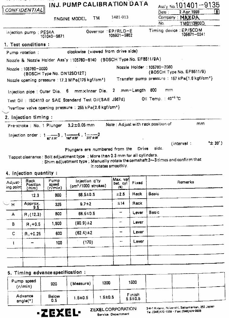
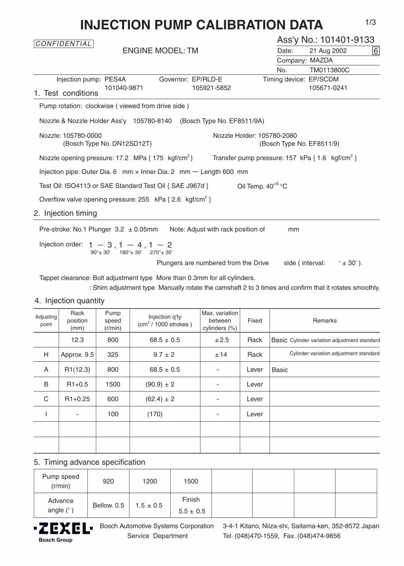
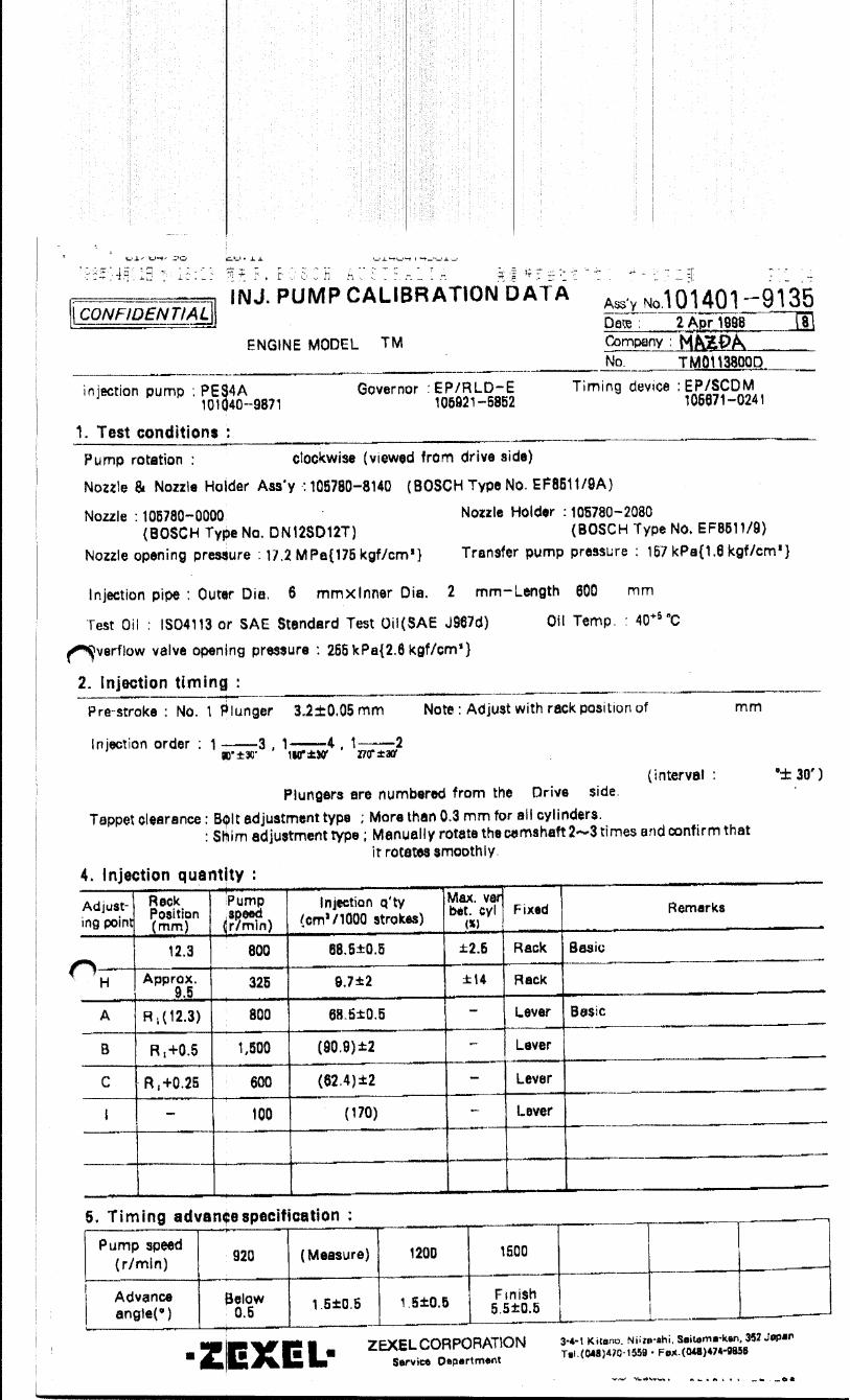
12.3 800 68.5 ± 0.5 ± 2.5 Rack
H Approx. 9.5 325 9.7 ± 2 ± 14 Rack
A R1(12.3) 800 68.5 ± 0.5 - Lever
B R1+0.5 1500 (90.9) ± 2 - Lever
C R1+0.25 600 (62.4) ± 2 - Lever
I - 100 (170) - Lever
Injection order: 1 3 , 1 4 , 1 290°± 30' 180°± 30' 270°± 30'
Pump speed(r/min)
920 1200 1500
Advanceangle (° )
Bellow. 0.5 1.5 ± 0.5 Finish
5.5 ± 0.5
4. Injection quantity
5. Timing advance specification
Bosch Automotive Systems Corporation
Service Department
3-4-1 Kitano, Niiza-shi, Saitama-ken, 352-8572 Japan
Tel. (048)470-1559, Fax. (048)474-9856
Company:
Ass'y No.: 101401-9133ENGINE MODEL: TM
No. Governor: EP/RLD-E Timing device: EP/SCDM
1. Test conditions
Date:
Pump rotation: clockwise ( viewed from drive side )
Injection pump: PES4A105921-5852 105671-0241
kgf/cm2 }
2. Injection timing
Pre-stroke: No.1 Plunger 3.2 ± 0.05mm mm
Plungers are numbered from the Drive ° ± 30' ).
Tappet clearance: Bolt adjustment type More than 0.3mm for all cylinders.
: Shim adjustment type Manually rotate the camshaft 2 to 3 times and confirm that it rotates smoothly.
CONFIDENTIAL
INJECTION PUMP CALIBRATION DATA
21 Aug 2002
TM0113800C
101040-9871
Injection pipe: Outer Dia. 6 mm × Inner Dia. 2 mm Length 600 mm
Nozzle opening pressure: 17.2 MPa { 175 kgf/cm2 }
Nozzle: 105780-0000 Nozzle Holder: 105780-2080(Bosch Type No. DN12SD12T) (Bosch Type No. EF8511/9)
Nozzle & Nozzle Holder Ass'y: 105780-8140 (Bosch Type No. EF8511/9A)
Overflow valve opening pressure: 255 kPa { 2.6 kgf/cm2 }
Test Oil: ISO4113 or SAE Standard Test Oil { SAE J967d } Oil Temp. 40+5 °C
side ( interval:
6
Transfer pump pressure: 157 kPa { 1.6
Note: Adjust with rack position of
MAZDA
1/3
Cylinder variation adjustment standard
Cylinder variation adjustment standard
Basic
Basic
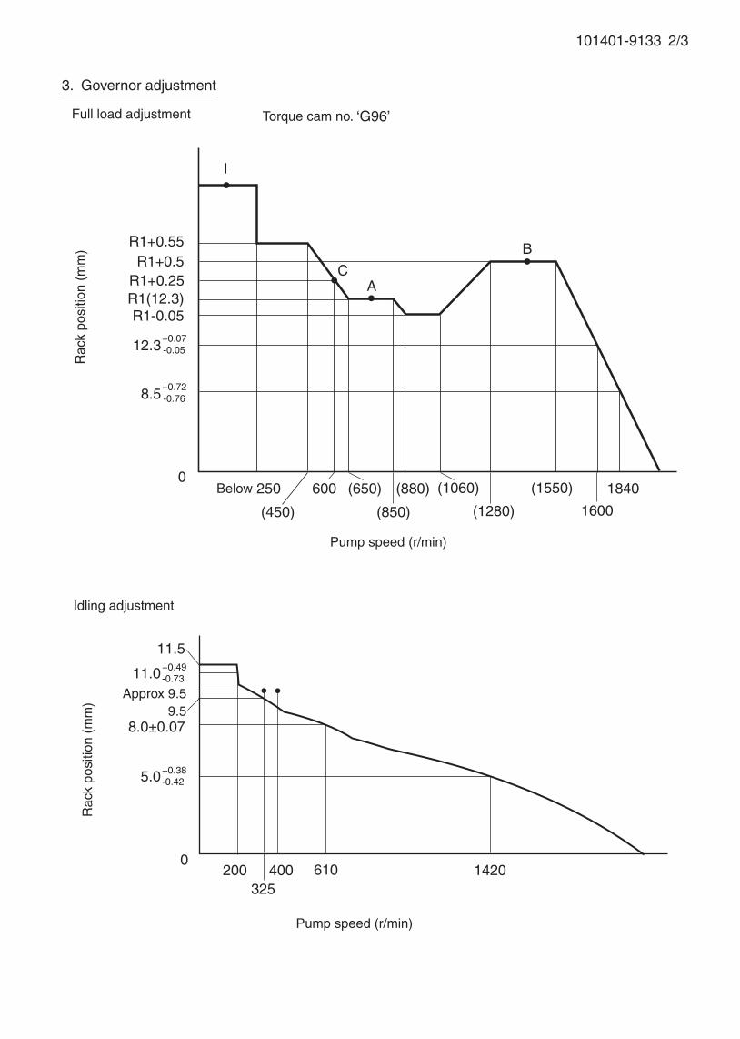
101401-9133 2/3
3. Governor adjustment
R1+0.55R1+0.5
R1+0.25R1(12.3)
0Below 250
(450)
600 (650) (880)
(1280)
1840(1060)
Rac
k po
sitio
n (m
m)
Pump speed (r/min)
(1550)
1600
AC
I
B
Torque cam no. ‘G96’
R1-0.05
11.5
0200
325400 610 1420
Rac
k po
sitio
n (m
m)
Pump speed (r/min)
Approx 9.5
5.0+0.38-0.42
8.0±0.07
Full load adjustment
Idling adjustment
+0.07-0.0512.3
+0.72-0.768.5
(850)
11.0+0.49-0.73
9.5
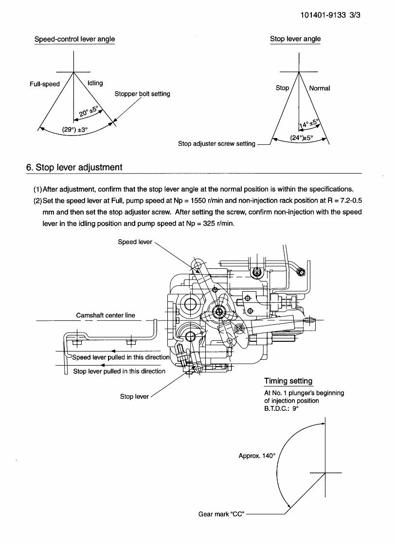


Adjustingpoint
Rackposition
(mm)
Pumpspeed(r/min)
Injection q'ty(cm3 / 1000 strokes )
Max. variationbetween
cylinders (%)Fixed Remarks
12.8 1000 70.5 ± 0.5 ± 2.5 Rack
H Approx 9.5 325 9 ± 2 ± 10 Rack
A R1(12.8) 1000 70.5 ± 0.5 - Lever Basic
B R1+0.5 1625 (84.1) ± 2 - Lever
C R1-0.5 625 (49.6) ± 2 - Lever
I - 100 Above 160 - Lever
Injection order: 1 3 , 1 4 , 1 290°± 30' 180°± 30' 270°± 30'
Pump speed(r/min)
700 1300 1600-25
Advanceangle (° )
Bellow 0.3 2 + 0.5 Finish
5-0.5
4. Injection quantity
5. Timing advance specification
Bosch Automotive Systems Corporation
Service Department
3-4-1 Kitano, Niiza-shi, Saitama-ken, 352-8572 Japan
Tel. (048)470-1559, Fax. (048)474-9856
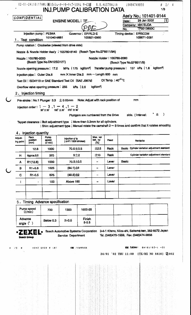
Company:
Ass'y No.: 101401-9143ENGINE MODEL: TF
No. Governor: EP/RLD-E Timing device: EP/SCDM
1. Test conditions
Date:
Pump rotation: clockwise ( viewed from drive side )
Injection pump: PES4A105921-5960 105671-0081
kgf/cm2 }
2. Injection timing
Pre-stroke: No.1 Plunger 3.3 ± 0.05mm mm
Plungers are numbered from the Drive ° ± 30' ).
Tappet clearance: Bolt adjustment type More than 0.3mm for all cylinders.
: Shim adjustment type Manually rotate the camshaft 2 to 3 times and confirm that it rotates smoothly.
CONFIDENTIAL
INJECTION PUMP CALIBRATION DATA
12 May 2003
TF2013800C
101040-9881
Injection pipe: Outer Dia. 6 mm × Inner Dia. 2 mm Length 600 mm
Nozzle opening pressure: 17.2 MPa { 175 kgf/cm2 }
Nozzle: 105780-0000 Nozzle Holder: 105780-2080(Bosch Type No. DN12SD12T) (Bosch Type No. EF8511/9)
Nozzle & Nozzle Holder Ass'y: 105780-8140 (Bosch Type No. EF8511/9A)
Overflow valve opening pressure: 255 ± 34 kPa { 2.6 ± 0.35 kgf/cm2 }
Test Oil: ISO4113 or SAE Standard Test Oil { SAE J967d } Oil Temp. 40+5 °C
side ( interval:
0
Transfer pump pressure: 157 kPa { 1.6
Note: Adjust with rack position of
MAZDA
1/4
Cylinder variation adjustment standard
Cylinder variation adjustment standard
Basic
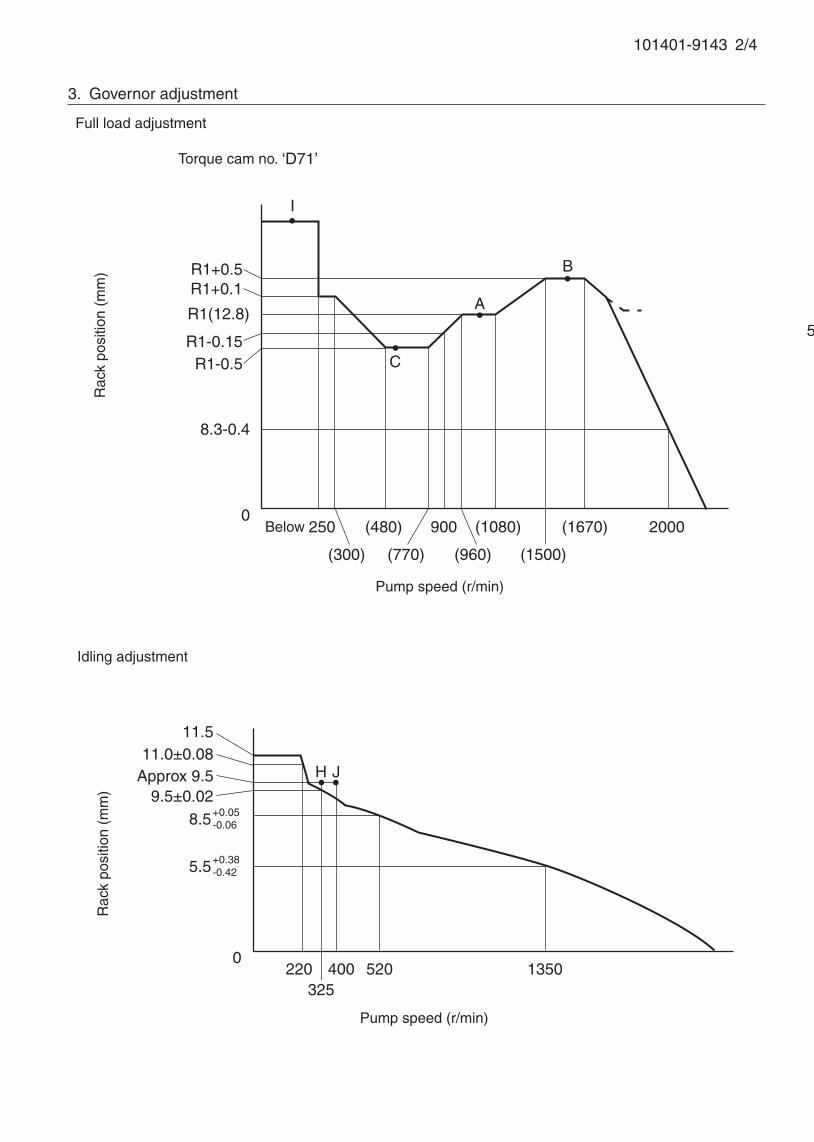
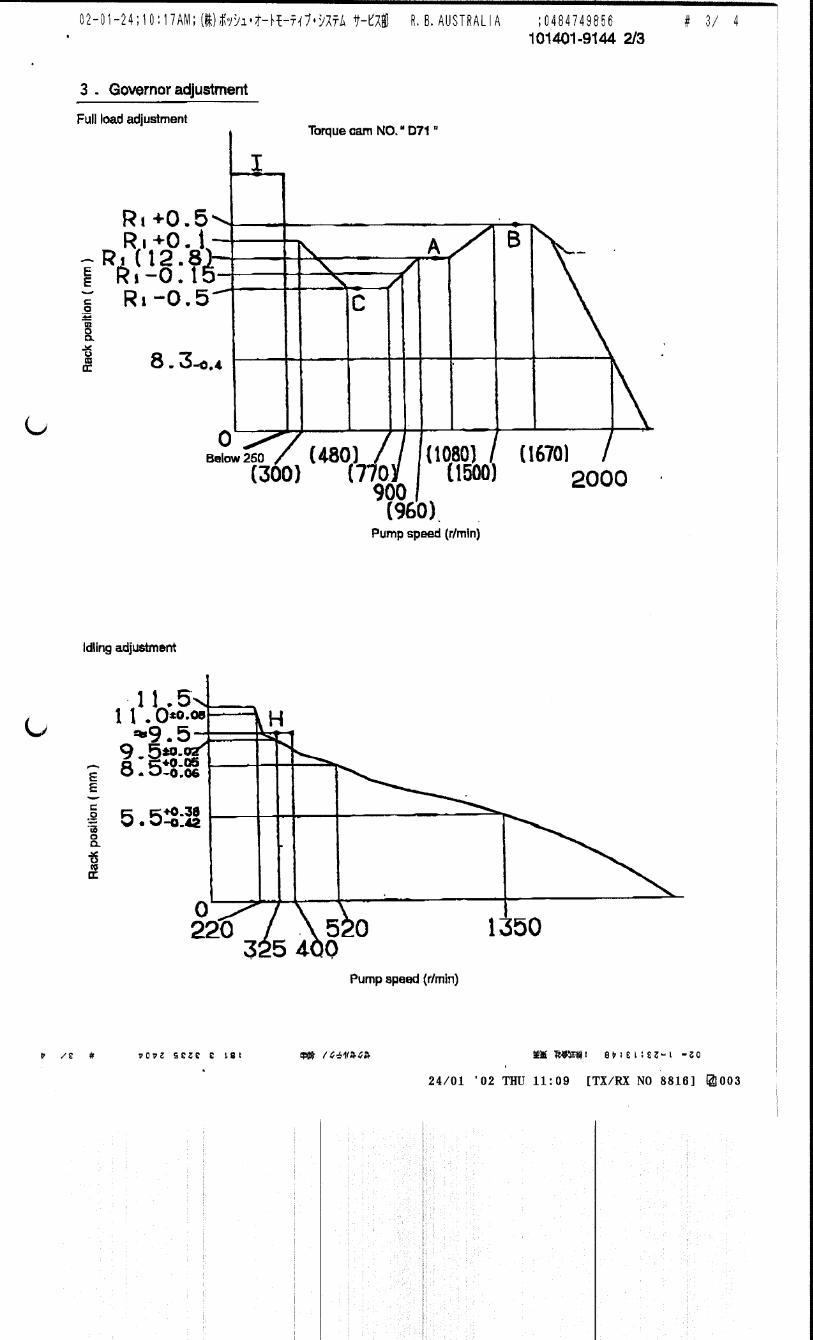
101401-9143 2/4
5. Timing advance specification
Adjust the clearance between the pickup and the gear tooth to 1-0.2mm.
3. Governor adjustment
0220
325400 1350
Rac
k po
sitio
n (m
m)
Pump speed (r/min)
11.5
8.5+0.05-0.06
R1(12.8)
0Below 250 (480) (1670)
A
B
Rac
k po
sitio
n (m
m)
Pump speed (r/min)
Torque cam no. ‘D71’
R1+0.5
(770)
900
(1500)
520
Approx 9.5
Full load adjustment
Idling adjustment
R1-0.15R1-0.5
8.3-0.4
2000
(300)
I
H J
C
R1+0.1
(960)
(1080)
11.0±0.08
9.5±0.02
5.5+0.38-0.42
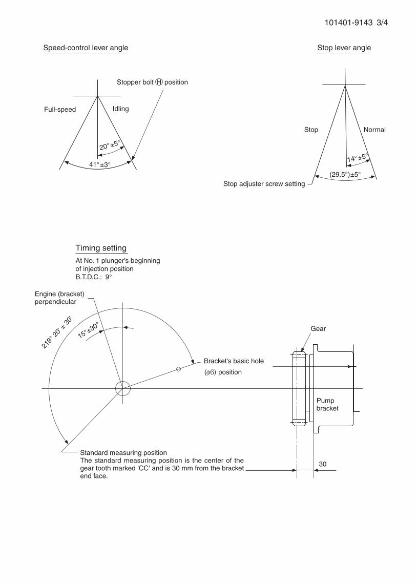
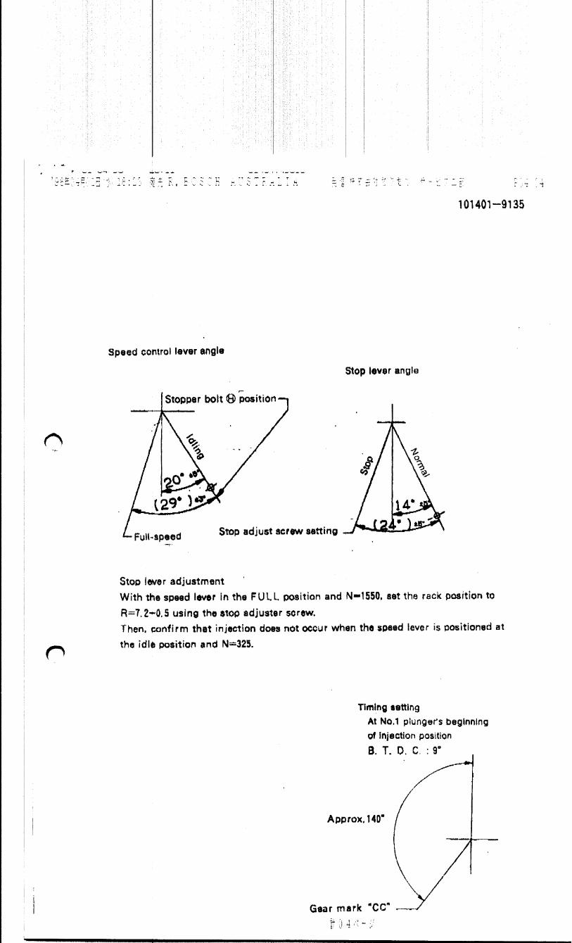
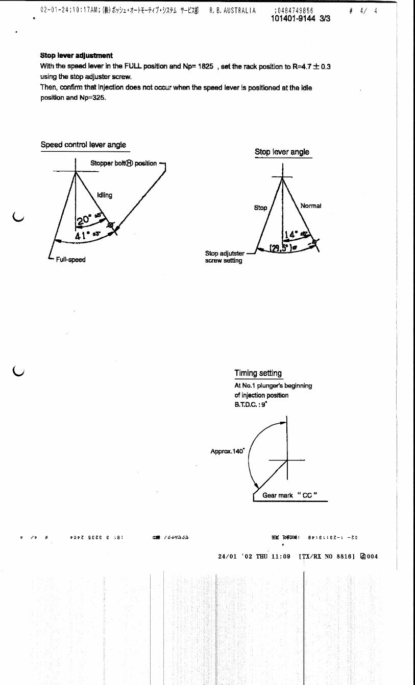
101401-9143 3/4
Bracket's basic hole
Stopper bolt H position
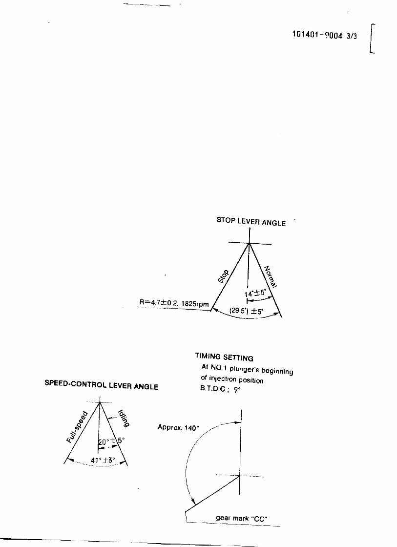
Speed-control lever angle
IdlingFull-speed
41°±3°
20°±5°
14°±5°
Stop adjuster screw setting
Stop lever angle
Stop Normal
(29.5°)±5°
Engine (bracket)perpendicular
30
Pumpbracket
Gear
Timing setting
At No. 1 plunger’s beginning of injection positionB.T.D.C.: 9°
Standard measuring positionThe standard measuring position is the center of the gear tooth marked 'CC' and is 30 mm from the bracket end face.
219°
20'
± 30
'
15°±30°
( 6) position

101401-9143 4/4
5. Timing advance specification
Adjust the clearance between the pickup and the gear tooth to 1-0.2mm.
6. Stop lever adjustment
Set the speed lever at Full and pump speed at Np = 1825 r/min, and then set the stop adjuster screw so
that the rack position is R = 4.7±0.3 mm. After setting the screw, confirm non-injection with the speed
lever in the idling position and pump speed at Np = 325 r/min.
Camshaft center line
Speed lever pulled in this direction
Stop lever pulled in this direction
Speed lever
Stop lever
Stop adjuster screw
Adjustingpoint
Rackposition
(mm)
Pumpspeed(r/min)
Injection quantity(cm3/1000 strokes)
Max. variationbetween
cylinders (%)Fixed Remarks
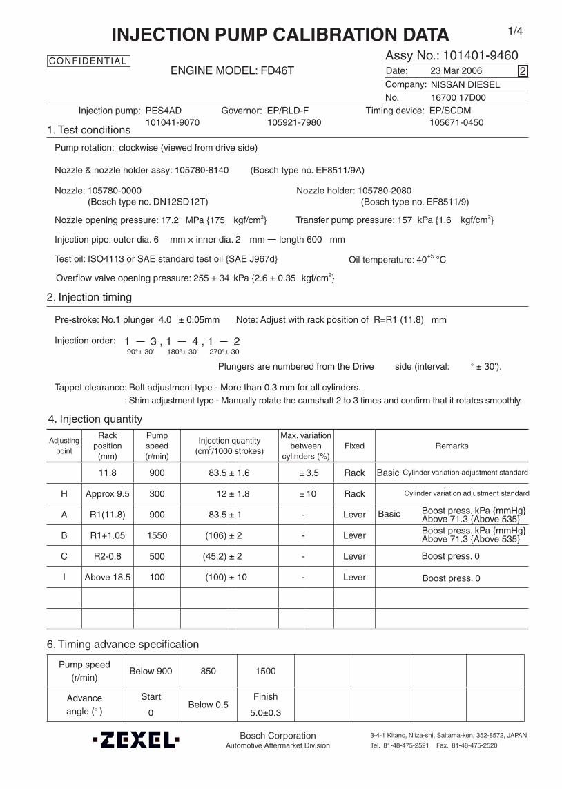
11.8 900 83.5 ± 1.6 ± 3.5 Rack
H Approx 9.5 300 12 ± 1.8 ± 10 Rack
A R1(11.8) 900 83.5 ± 1 - Lever
B R1+1.05 1550 (106) ± 2 - Lever
C R2-0.8 500 (45.2) ± 2 - Lever
I Above 18.5 100 (100) ± 10 - Lever
Oil temperature: 40+5 °C
Injection order:
4. Injection quantity
6. Timing advance specification
Company:
Assy No.: 101401-9460ENGINE MODEL: FD46T
No. Governor: EP/RLD-F Timing device: EP/SCDM
1. Test conditions
Date:
Pump rotation: clockwise (viewed from drive side)
Injection pump: PES4AD105921-7980 105671-0450
kgf/cm2}
2. Injection timing
Pre-stroke: No.1 plunger 4.0 ± 0.05mm mm
Plungers are numbered from the Drive ° ± 30').
Tappet clearance: Bolt adjustment type - More than 0.3 mm for all cylinders.: Shim adjustment type - Manually rotate the camshaft 2 to 3 times and confirm that it rotates smoothly.
CONFIDENTIAL
INJECTION PUMP CALIBRATION DATA
23 Mar 2006
16700 17D00
101041-9070
Injection pipe: outer dia. 6 mm × inner dia. 2 mm length 600 mm
Nozzle opening pressure: 17.2 MPa {175 kgf/cm2}
Test oil: ISO4113 or SAE standard test oil {SAE J967d}
side (interval:
2
Transfer pump pressure: 157 kPa {1.6
Note: Adjust with rack position of R=R1 (11.8)
1/4
Boost press. kPa {mmHg}Above 71.3 {Above 535}
Boost press. 0
Cylinder variation adjustment standardBasic
1 3 , 1 4 , 1 290°± 30' 180°± 30' 270°± 30'
Overflow valve opening pressure: 255 ± 34 kPa {2.6 ± 0.35 kgf/cm2}
NISSAN DIESEL
Nozzle: 105780-0000 Nozzle holder: 105780-2080(Bosch type no. DN12SD12T) (Bosch type no. EF8511/9)
Nozzle & nozzle holder assy: 105780-8140 (Bosch type no. EF8511/9A)
Pump speed(r/min)
Below 900 850 1500
Advanceangle (° )
Start
0 Below 0.5
Finish
5.0±0.3
Bosch CorporationAutomotive Aftermarket Division
3-4-1 Kitano, Niiza-shi, Saitama-ken, 352-8572, JAPAN
Tel. 81-48-475-2521 Fax. 81-48-475-2520
Cylinder variation adjustment standard
Basic
Boost press. kPa {mmHg}Above 71.3 {Above 535}
Boost press. 0
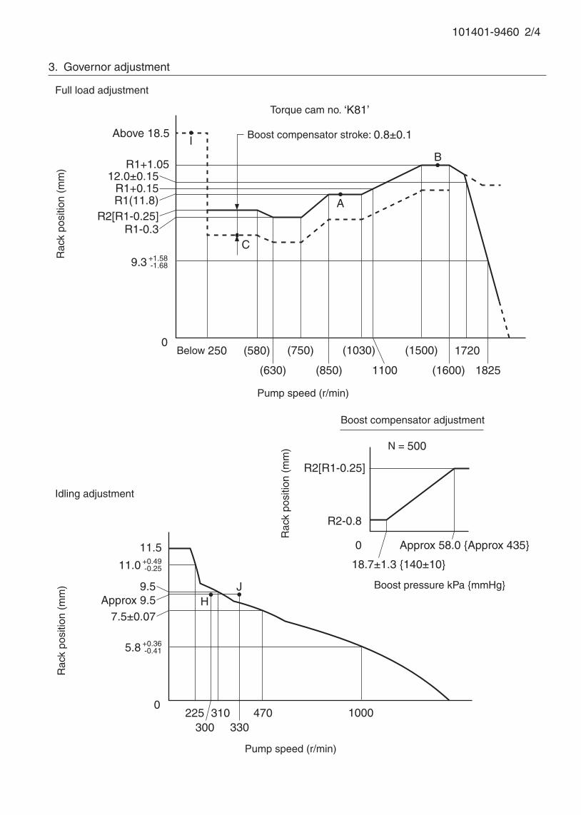
101401-9460 2/4
3. Governor adjustment
I
0
Rac
k po
sitio
n (m
m)
Pump speed (r/min)
0Below 250 (1500)
B
A
Rac
k po
sitio
n (m
m)
Pump speed (r/min)
Torque cam no. ‘K81’
R1+1.05
(580)
(1600)
1720
7.5±0.07 Approx 9.5
Full load adjustment
Idling adjustment
Above 18.5
HJ
225300
310
12.0±0.15
1100
9.3
R1+0.15
(1030)
330
Boost compensator stroke: 0.8±0.1
R1(11.8)
(850)
11.5
9.5
1000
R2[R1-0.25]
R2-0.8
0
18.7±1.3 {140±10}
Approx 58.0 {Approx 435}
N = 500
Rac
k po
sitio
n (m
m)
Boost pressure kPa {mmHg}
Boost compensator adjustment
470
(630)
C
R2[R1-0.25]R1-0.3
+1.58-1.68
(750)
1825
11.0 +0.49-0.25
5.8 +0.36-0.41

101401-9460 3/4
Bolts A
Potentiometer
5.0±
0.02
V
Potentiometer connections
Output voltage
Direction of potentiometer rotation
Idle Full
(5.0)
(3.83)±0.2
0.5±0.3
0
Specified output voltage
1
2
3
Vol
tage
(V
)
5. Potentiometer adjustment
(1) Supply DC 5.0±0.2V to the potentiometer harness terminals shown in the circuit below to obtain the
specified output voltage.
(2) Fix the speed lever in the full position and loosen bolts A shown below.
Then, move the potentiometer left and right until the output voltage for the full position is as specified.
Tighten bolts A, move the speed lever between full and idle and confirm that the values for full and idle
are as specified.
Potentiometer voltage: Measure actual lever angle at 2.84±0.3 V
101401-9460 4/4
Stopper bolt H position
Speed-control lever angle
Idling
Full-speed
70°±5°
(40)°±3°
Stop lever angle
Stop Normal
Center of threaded hole
10°±5°
29°±5°
Timing setting
At No. 1 plunger’s beginning of injection positionB.T.D.C.: 8°
Approx. 50°
(Gear mark position)

Adjustingpoint
Rackposition
(mm)
Pumpspeed(r/min)
Injection q'ty(cm3 / 1000 strokes )
Max. variationbetween
cylinders (%)Fixed Remarks
A 9.3 950 84.7 ± 1 ± 2.5 Lever Basic
Approx. 5.9 400 8 ± 1.3 ± 14 Rack
D - 100 60 + 5 - Lever Rack limit
Injection order: 1 3 , 1 4 , 1 290°± 30' 180°± 30' 270°± 30'
Pump speed(r/min)
Advanceangle (° )
4. Injection quantity
5. Timing advance specification
Bosch Automotive Systems Corporation
Service Department
3-4-1 Kitano, Niiza-shi, Saitama-ken, 352-8572 Japan
Tel. (048)470-1559, Fax. (048)474-9856
Company:
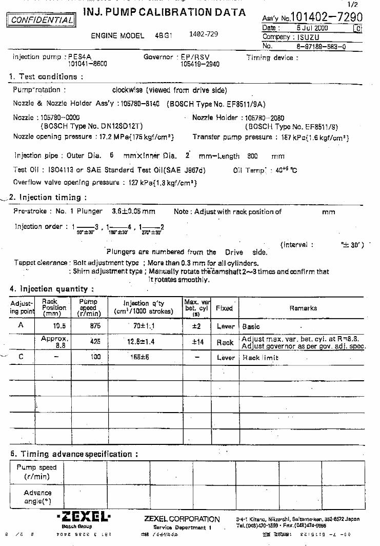
Ass'y No.: 101402-9460ENGINE MODEL: S4K-T
No. Governor: EP/RSV Timing device:
1. Test conditions
Date:
Pump rotation: clockwise ( viewed from drive side )
Injection pump: PES4A105419-1011
kgf/cm2 }
2. Injection timing
Pre-stroke: No.1 Plunger 3.6 ± 0.05mm mm
Plungers are numbered from the Drive ° ± 30' ).
Tappet clearance: Bolt adjustment type More than 0.3mm for all cylinders.
: Shim adjustment type Manually rotate the camshaft 2 to 3 times and confirm that it rotates smoothly.
CONFIDENTIAL
INJECTION PUMP CALIBRATION DATA
24 Jul 2002
34261-02080
101041-8040
Injection pipe: Outer Dia. 6 mm × Inner Dia. 2 mm Length 600 mm
Nozzle opening pressure: 17.2 MPa { 175 kgf/cm2 }
Nozzle: 105780-0000 Nozzle Holder: 105780-2080(Bosch Type No. DN12SD12T) (Bosch Type No. EF8511/9)
Nozzle & Nozzle Holder Ass'y: 105780-8140 (Bosch Type No. EF8511/9A)
Overflow valve opening pressure: 255 kPa { 2.6 kgf/cm2 }
Test Oil: ISO4113 or SAE Standard Test Oil { SAE J967d } Oil Temp. 40+5 °C
side ( interval:
0
Transfer pump pressure: 157 kPa { 1.6
Note: Adjust with rack position of
MITSUBISHI
1/3
Adjust max. var. bet. cyl. of R≒ 5.9.Adjust governor as per gov. adj. spec.
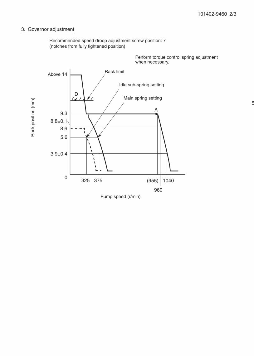
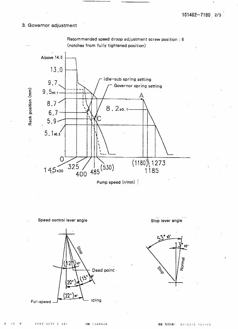
101402-9460 2/3
5. Timing advance specification
Adjust the clearance between the pickup and the gear tooth to 1-0.2mm.
3. Governor adjustment
Pump speed (r/min)
0325
8.8±0.1
960
(955) 1040
D
A9.3
8.6
Rac
k po
sitio
n (m
m)
5.6
Above 14
3.9±0.4
Rack limit
Idle sub-spring setting
Main spring setting
Recommended speed droop adjustment screw position: 7(notches from fully tightened position)
375
Perform torque control spring adjustment when necessary.
101402-9460 3/3
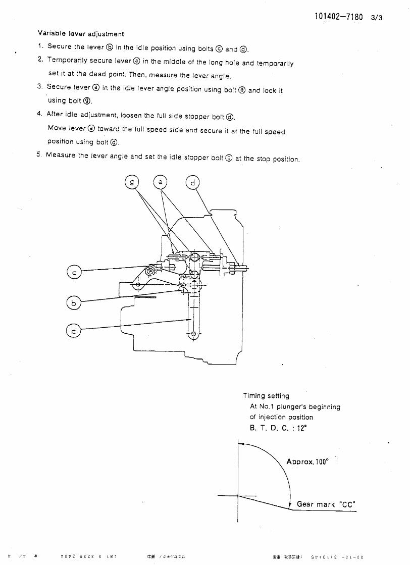
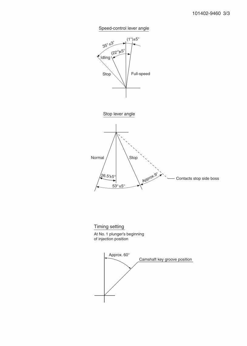
Speed-control lever angle
Idling
Approx.9°
Stop lever angle
Stop
Full-speed
Normal
Camshaft key groove position
35°±3°
(22°)±5°
(1°)±5°
Contacts stop side boss
53°±5°
26.5°±5°
Stop
Timing setting
At No. 1 plunger’s beginning of injection position
Approx. 60°

Adjustingpoint
Rackposition
(mm)
Pumpspeed(r/min)
Injection q'ty(cm3 / 1000 strokes )
Max. variationbetween
cylinders (%)Fixed Remarks
A 8.2 1000 56 ± 1 ± 2.5 Lever Basic
- Approx.6.9 425 12 ± 1.3 ± 1.4 Rack
D - 100 70 + 10 - Lever Rack limit
Injection order: 1 3 , 1 4 , 1 290°± 30' 180°± 30' 270°± 30'
Pump speed(r/min)
Advanceangle (° )
4. Injection quantity
5. Timing advance specification
Bosch Automotive Systems Corporation
Service Department
3-4-1 Kitano, Niiza-shi, Saitama-ken, 352-8572 Japan
Tel. (048)470-1559, Fax. (048)474-9856
Company:
Ass'y No.: 101402-9810ENGINE MODEL: S4K
No. Governor: EP/RSV Timing device:
1. Test conditions
Date:
Pump rotation: clockwise ( viewed from drive side )
Injection pump: PES4A105419-3440
kgf/cm2 }
2. Injection timing
Pre-stroke: No.1 Plunger 3.6 ± 0.05mm mm
Plungers are numbered from the Drive ° ± 30' ).
Tappet clearance: Bolt adjustment type More than 0.3mm for all cylinders.
: Shim adjustment type Manually rotate the camshaft 2 to 3 times and confirm that it rotates smoothly.
CONFIDENTIAL
INJECTION PUMP CALIBRATION DATA
11 Jun 2002
I
34261-04050
101041-8040
Injection pipe: Outer Dia. 6 mm × Inner Dia. 2 mm Length 600 mm
Nozzle opening pressure: 17.2 MPa { 175 kgf/cm2 }
Nozzle: 105780-0000 Nozzle Holder: 105780-2080(Bosch Type No. DN12SD12T) (Bosch Type No. EF8511/9)
Nozzle & Nozzle Holder Ass'y: 105780-8140 (Bosch Type No. EF8511/9A)
Overflow valve opening pressure: 255 kPa { 2.6 kgf/cm2 }
Test Oil: ISO4113 or SAE Standard Test Oil { SAE J967d } Oil Temp. 40+5 °C
side ( interval:
1
Transfer pump pressure: 157 kPa { 1.6
Note: Adjust with rack position of
MITSUBISHI
1/3
Adjust max. var. bet. cyl. of R≒ 6.9.Adjust governor as per gov. adj. spec.

3. Governor adjustment
101402-9810 2/3
Pump speed (r/min)
0(300)
400
425
7.7±0.1
1025
(1015) 1100
D
A
6.0
Rac
k po
sitio
n (m
m)
Above 14
4.5±0.4
Rack limit
Recommended speed droop adjustment screw position: 15(notches from fully tightened position)
(450)
8.6
8.2
1.0±
0.1
Difference in control rack position between 1000 r/min and 250 r/min
Idle sub-spring setting:4.5-0.5 mm
101402-9810 3/3
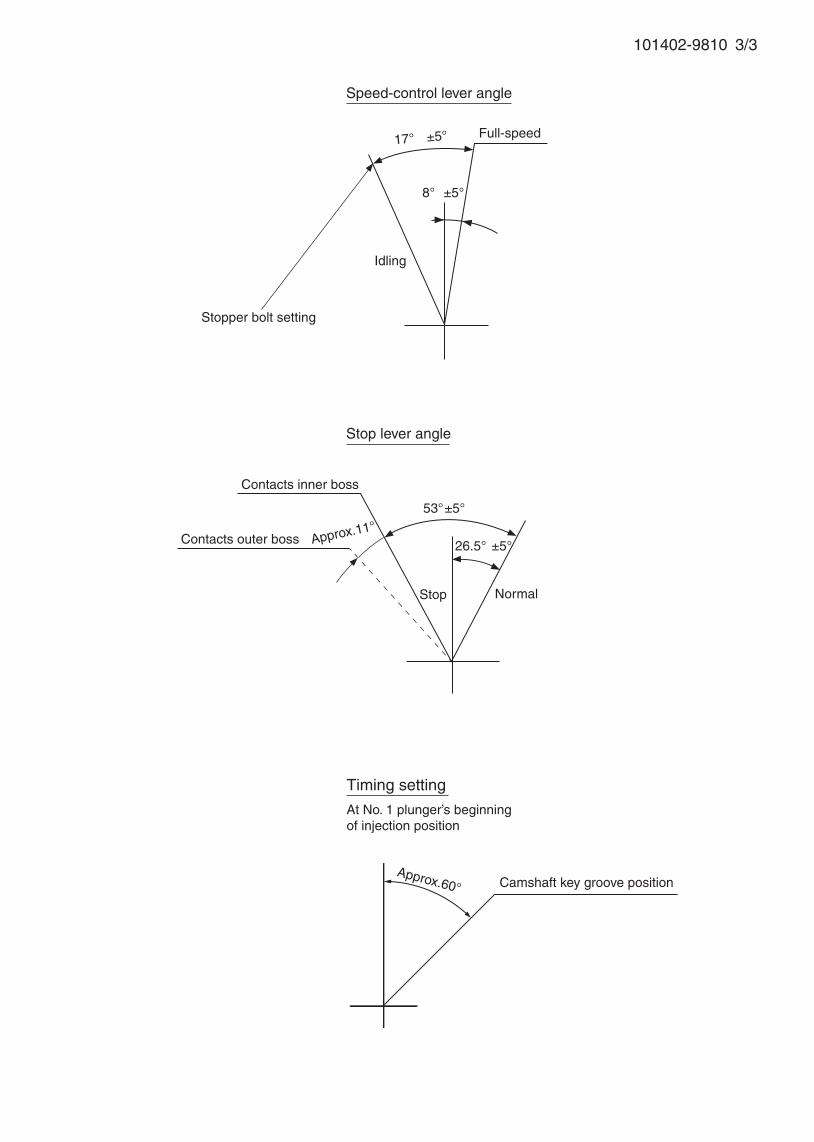
Speed-control lever angle
Idling
Stopper bolt setting
Stop lever angle
Stop
Full-speed
Normal
17° ±5°
Camshaft key groove positionApprox.60°
8° ±5°
Approx.11°53°±5°
26.5° ±5°Contacts outer boss
Contacts inner boss
Timing setting
At No. 1 plunger’s beginning of injection position

Adjustingpoint
Rackposition
(mm)
Pumpspeed(r/min)
Injection q'ty(cm3 / 1000 strokes )
Max. variationbetween
cylinders (%)Fixed Remarks
A 8.9 1000 72.5 ± 1 ± 2.5 Rack Basic
- Approx.6.8 425 12 ± 1.3 ± 14 Rack
D - 100 60 + 10 - Lever Rack limit
Injection order: 1 3 , 1 4 , 1 290°± 30' 180°± 30' 270°± 30'
Pump speed(r/min)
Advanceangle (° )
4. Injection quantity
5. Timing advance specification
Bosch Automotive Systems Corporation
Service Department
3-4-1 Kitano, Niiza-shi, Saitama-ken, 352-8572 Japan
Tel. (048)470-1559, Fax. (048)474-9856
Company:
Ass'y No.: 101402-9880ENGINE MODEL:S4K-T
No. Governor: EP/RSV Timing device:
1. Test conditions
Date:
Pump rotation: clockwise ( viewed from drive side )
Injection pump: PES4A105419-3450
kgf/cm2 }
2. Injection timing
Pre-stroke: No.1 Plunger 3.6 ± 0.05mm mm
Plungers are numbered from the Drive ° ± 30' ).
Tappet clearance: Bolt adjustment type More than 0.3mm for all cylinders.
: Shim adjustment type Manually rotate the camshaft 2 to 3 times and confirm that it rotates smoothly.
CONFIDENTIAL
INJECTION PUMP CALIBRATION DATA
11 Jun 2002
34261-04060
101041-8040
Injection pipe: Outer Dia. 6 mm × Inner Dia. 2 mm Length 600 mm
Nozzle opening pressure: 17.2 MPa { 175 kgf/cm2 }
Nozzle: 105780-0000 Nozzle Holder: 105780-2080(Bosch Type No. DN12SD12T) (Bosch Type No. EF8511/9)
Nozzle & Nozzle Holder Ass'y: 105780-8140 (Bosch Type No. EF8511/9A)
Overflow valve opening pressure: 255 kPa { 2.6 kgf/cm2 }
Test Oil: ISO4113 or SAE Standard Test Oil { SAE J967d } Oil Temp. 40+5 °C
side ( interval:
1
Transfer pump pressure: 157 kPa { 1.6
Note: Adjust with rack position of
MITSUBISHI
1/3
Adjust max. var. bet. cyl. of R≒ 6.8.Adjust governor as per gov. adj. spec.
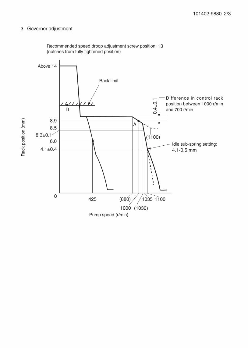
3. Governor adjustment
101402-9880 2/3
Pump speed (r/min)
0425
8.3±0.1
1000
(880)
(1100)
D
A
6.0
Rac
k po
sitio
n (m
m)
Above 14
4.1±0.4
Rack limit
Recommended speed droop adjustment screw position: 13(notches from fully tightened position)
8.9
8.5
0.4±
0.1 Difference in control rack
position between 1000 r/min and 700 r/min
Idle sub-spring setting:4.1-0.5 mm
(1030)
1035 1100
101402-9880 3/3
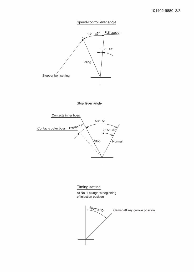
Approx.60°
Speed-control lever angle
Idling
Stopper bolt setting
Stop lever angle
Stop
Full-speed
Normal
18° ±5°
Camshaft key groove position
2° ±5°
Approx.11°53°±5°
26.5° ±5°Contacts outer boss
Contacts inner boss
Timing setting
At No. 1 plunger’s beginning of injection position
Adjustingpoint
Rackposition
(mm)
Pumpspeed(r/min)
Injection quantity(cm3/1000 strokes)
Max. variationbetween
cylinders (%)Fixed Remarks
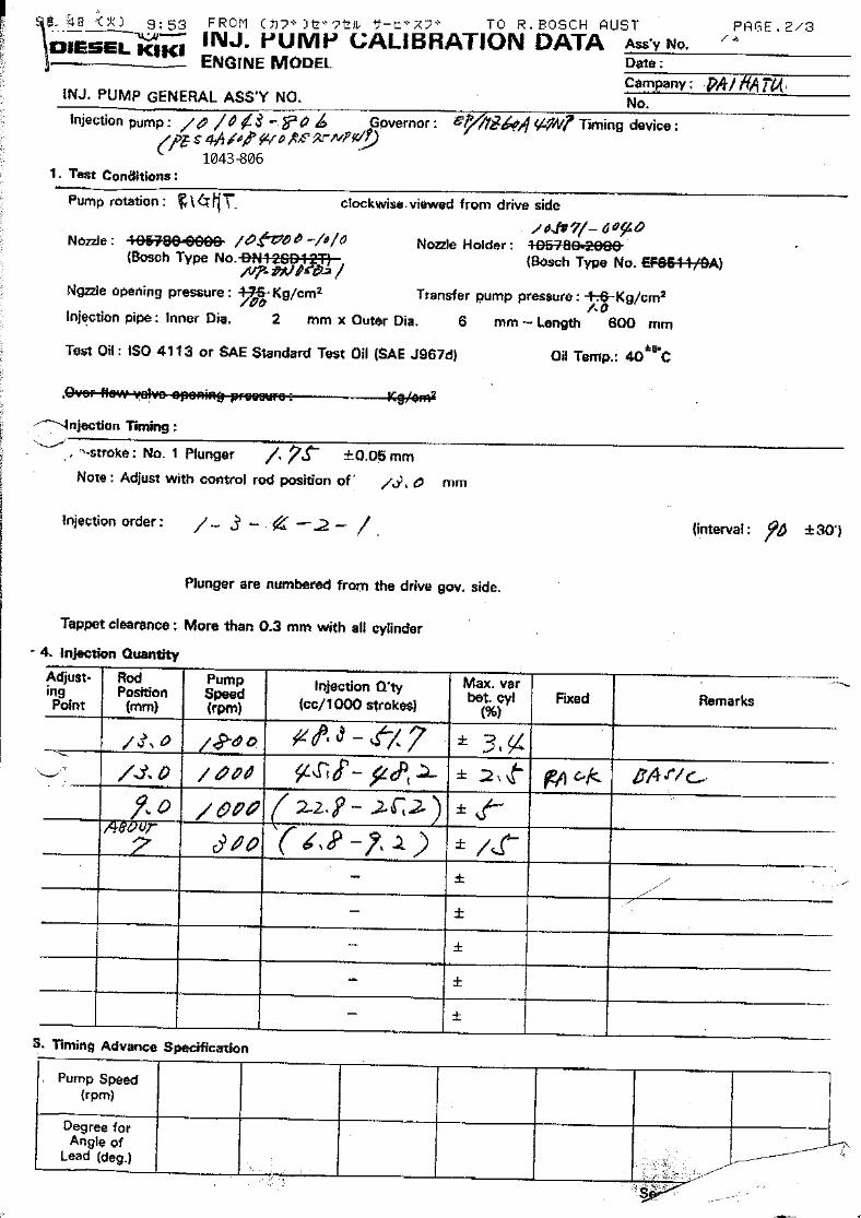
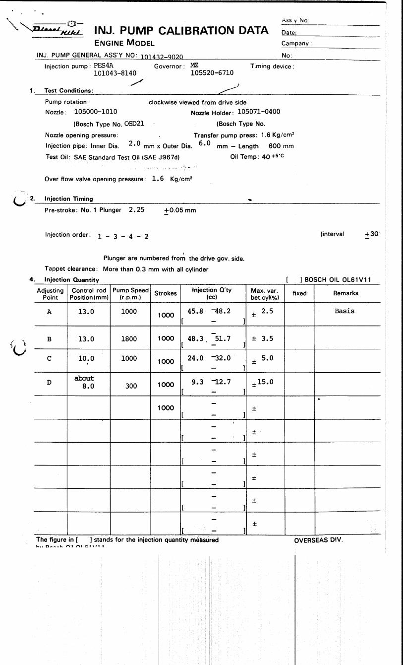
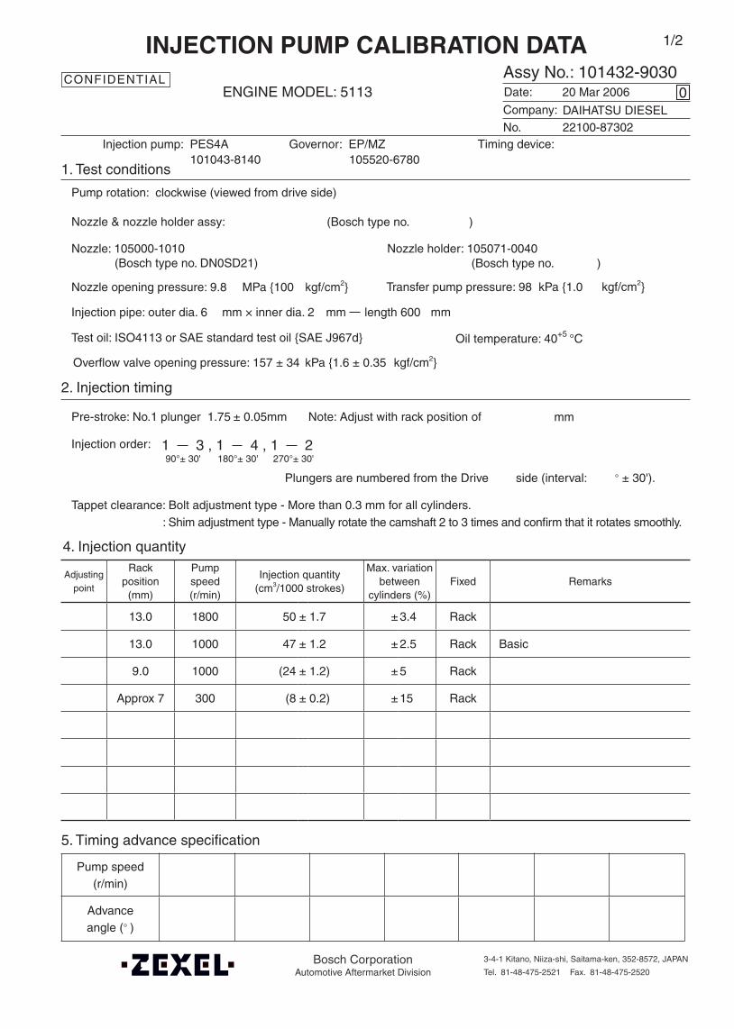
13.0 1800 50 ± 1.7 ± 3.4 Rack
13.0 1000 47 ± 1.2 ± 2.5 Rack Basic
9.0 1000 (24 ± 1.2) ± 5 Rack
Approx 7 300 (8 ± 0.2) ± 15 Rack
Oil temperature: 40+5 °C
Injection order:
4. Injection quantity
5. Timing advance specification
Company:
Assy No.: 101432-9030ENGINE MODEL: 5113
No. Governor: EP/MZ Timing device:
1. Test conditions
Date:
Pump rotation: clockwise (viewed from drive side)
Injection pump: PES4A105520-6780
kgf/cm2}
2. Injection timing
Pre-stroke: No.1 plunger 1.75 ± 0.05mm mm
Plungers are numbered from the Drive ° ± 30').
Tappet clearance: Bolt adjustment type - More than 0.3 mm for all cylinders.: Shim adjustment type - Manually rotate the camshaft 2 to 3 times and confirm that it rotates smoothly.
CONFIDENTIAL
INJECTION PUMP CALIBRATION DATA
20 Mar 2006
22100-87302
101043-8140
Injection pipe: outer dia. 6 mm × inner dia. 2 mm length 600 mm
Nozzle opening pressure: 9.8 MPa {100 kgf/cm2}
Test oil: ISO4113 or SAE standard test oil {SAE J967d}
side (interval:
0
Transfer pump pressure: 98 kPa {1.0
Note: Adjust with rack position of
DAIHATSU DIESEL
1/2
1 3 , 1 4 , 1 290°± 30' 180°± 30' 270°± 30'
Overflow valve opening pressure: 157 ± 34 kPa {1.6 ± 0.35 kgf/cm2}
Nozzle: 105000-1010 Nozzle holder: 105071-0040(Bosch type no. DN0SD21) (Bosch type no. )
Nozzle & nozzle holder assy: (Bosch type no. )
Pump speed(r/min)
Advanceangle (° )
Bosch CorporationAutomotive Aftermarket Division
3-4-1 Kitano, Niiza-shi, Saitama-ken, 352-8572, JAPAN
Tel. 81-48-475-2521 Fax. 81-48-475-2520

101432-9030 2/2
3. Governor adjustment
13
0
9
Rac
k po
sitio
n (m
m)
Negative pressure kPa {mmAq}
Pneumatic governor
Operate injection pump at 500 r/min and increase negative pressure gradually from lower pressure.
7
3.43±0.1{350±15}
4.31±0.2{440±20}
7.26±0.3{740±30}

Adjustingpoint
Rackposition
(mm)
Pumpspeed(r/min)
Injection q'ty(cm3 / 1000 strokes )
Max. variationbetween
cylinders (%)Fixed Remarks
A 9.9 1300 42.2 ± 1 ± 2.5 Lever Basic
C Approx. 6.0 500 8 ± 1.1 ± 14 Rack
E - 100 65 ± 5 - Lever Rack limit
Injection order: 1 3 , 1 4 , 1 290°± 30' 180°± 30' 270°± 30'
Pump speed(r/min)
Below
750700 1300 (Measure))
Advanceangle (° )
Start
0 Below 0.5 1.6 ± 0.5
Finish
(6.0)
4. Injection quantity
5. Timing advance specification
Bosch Automotive Systems Corporation
Service Department
3-4-1 Kitano, Niiza-shi, Saitama-ken, 352-8572 Japan
Tel. (048)470-1559, Fax. (048)474-9856
Company:
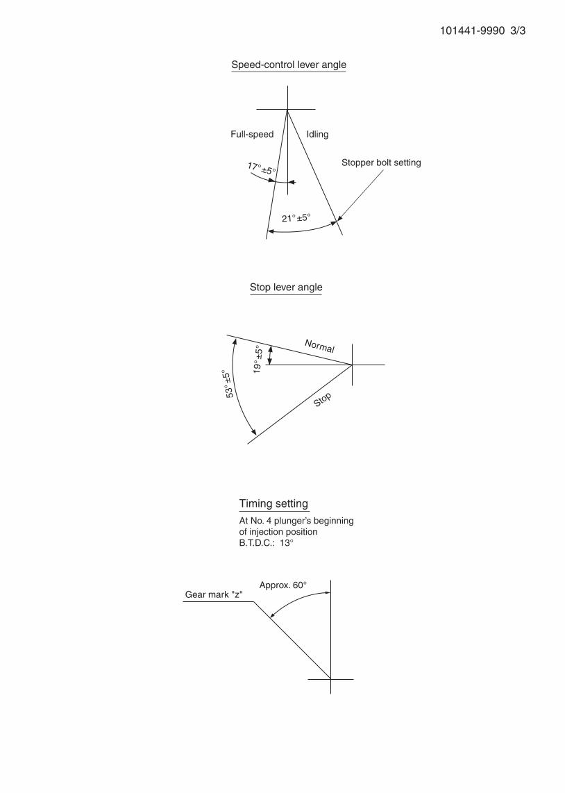
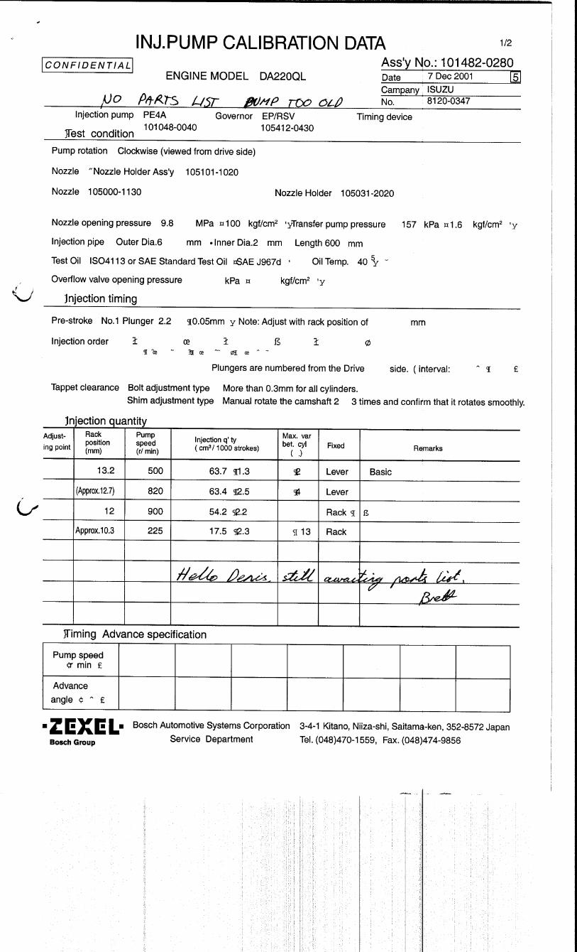
Ass'y No.: 101441-9990ENGINE MODEL: DC24T
No. Governor: EP/RSV Timing device: EP/SCD
1. Test conditions
Date:
Pump rotation: counter clockwise ( viewed from drive side )
Injection pump: PES4A105419-4360 105621-0500
kgf/cm2 }
2. Injection timing
Pre-stroke: No.1 Plunger 2.25± 0.05mm mm
Plungers are numbered from the Drive ° ± 30' ).
Tappet clearance: Bolt adjustment type More than 0.3mm for all cylinders.
: Shim adjustment type Manually rotate the camshaft 2 to 3 times and confirm that it rotates smoothly.
CONFIDENTIAL
INJECTION PUMP CALIBRATION DATA
7 Feb 2003
DAEWOO HEAVY
101044-9170
Injection pipe: Outer Dia. 6 mm × Inner Dia. 2 mm Length 600 mm
Nozzle opening pressure: 17.2 MPa { 175 kgf/cm2 }
Nozzle: 105780-0000 Nozzle Holder: 105780-2080(Bosch Type No. DN12SD12T) (Bosch Type No. EF8511/9)
Nozzle & Nozzle Holder Ass'y: 105780-8140 (Bosch Type No. EF8511/9A)
Overflow valve opening pressure: 157 ± 34 kPa { 1.6 ± 0.35 kgf/cm2 }
Test Oil: ISO4113 or SAE Standard Test Oil { SAE J967d } Oil Temp. 40+5 °C
side ( interval:
0
Transfer pump pressure: 157 kPa { 1.6
Note: Adjust with rack position of
1/3
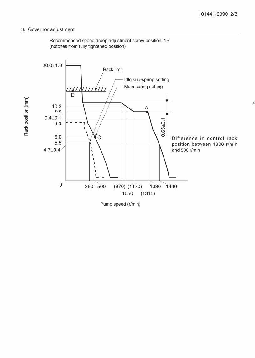
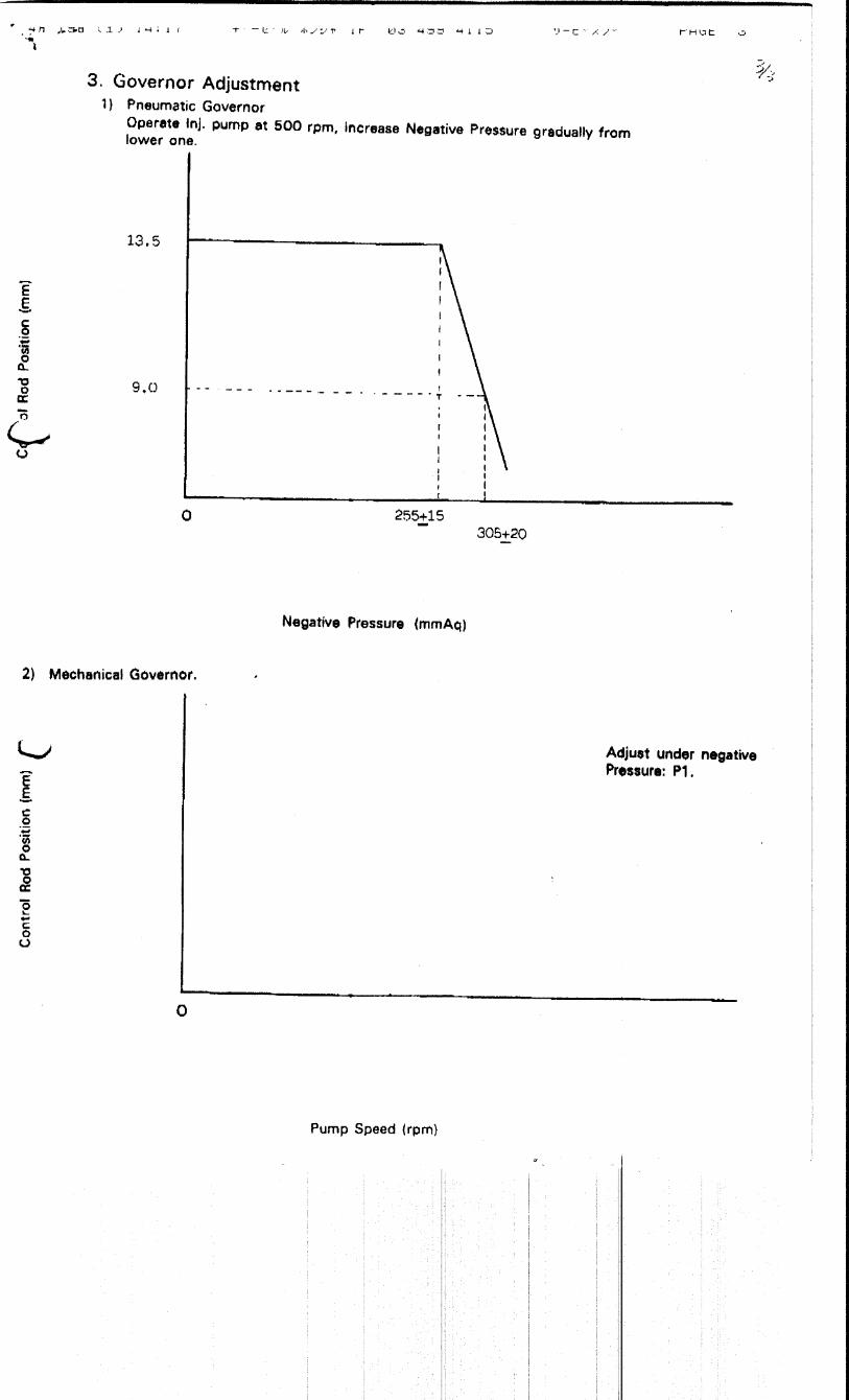
101441-9990 2/3
5. Timing advance specification
Adjust the clearance between the pickup and the gear tooth to 1-0.2mm.
3. Governor adjustment
Recommended speed droop adjustment screw position: 16 (notches from fully tightened position)
20.0+1.0
9.910.3
0
4.7±0.4
(1170)
A
Rac
k po
sitio
n (m
m)
Pump speed (r/min)
0.65
±0.
1
500
Rack limit
9.0
6.0
360 (970)1050
1330 1440
C Di f ference in cont ro l rack position between 1300 r/min and 500 r/min
9.4±0.1
(1315)
E
5.5
Idle sub-spring setting
Main spring setting
101441-9990 3/3
Speed-control lever angle
Idling
Stopper bolt setting
Full-speed
21°±5°
17°±5°
Stop lever angle
Stop
Normal
53°
±5°
19°
±5°
Timing setting
At No. 4 plunger’s beginning of injection positionB.T.D.C.: 13°
Approx. 60°Gear mark "z"

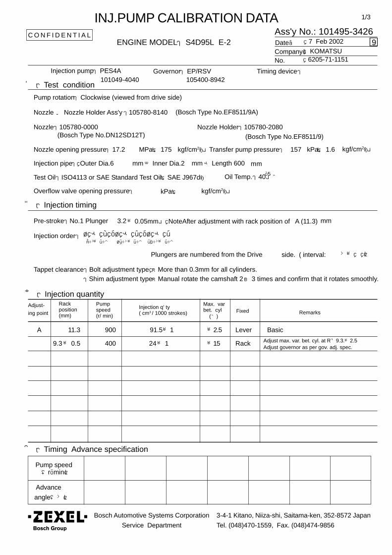
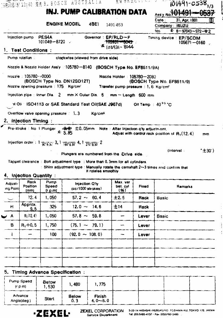
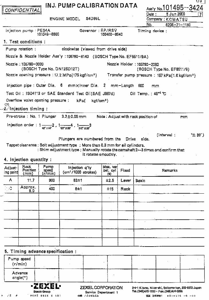
Ass'y No.: 101495-3426
1/3
ENGINE MODEL: S4D95L E-2
No.
Governor: EP/RSV Timing device:
1.Test condition
Date:
4.Injection quantity
5.Timing Advance specification
Pump speed(r/min)
Advance
angle(°)
Pump rotation: Clockwise (viewed from drive side)
Injection pump: PES4A 105400-8942
kgf/cm2}
2.Injection timing
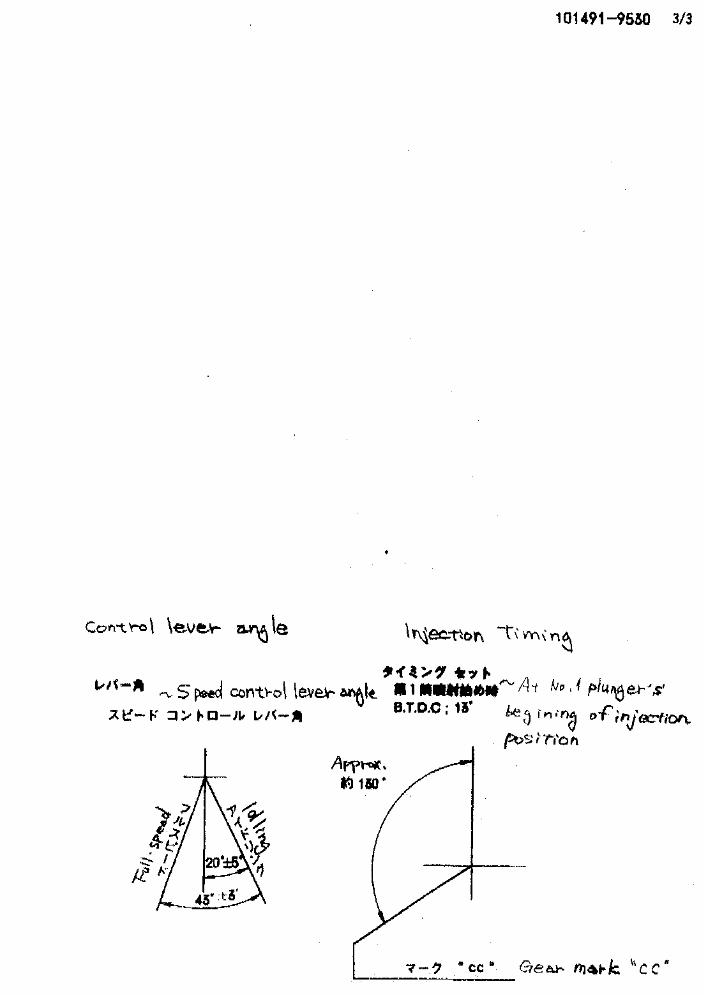
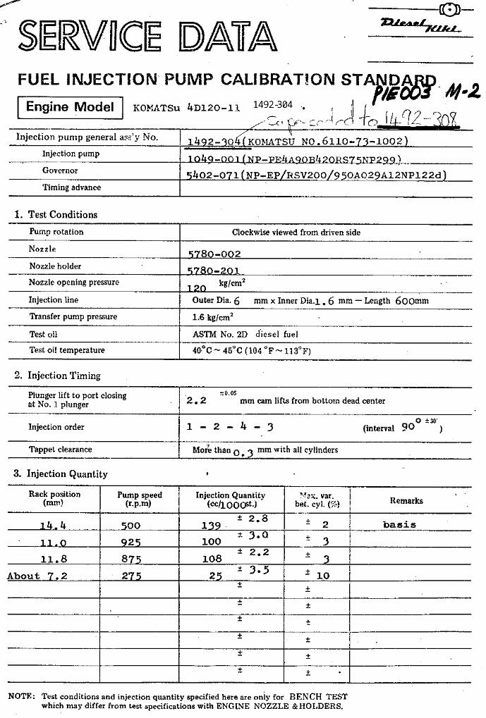
Pre-stroke:No.1 Plunger 3.2±0.05mm NoteAfter adjustment with rack position of A (11.3) mm
Injection order:
Plungers are numbered from the Drive °± )
Tappet clearance:Bolt adjustment type ;More than 0.3mm for all cylinders.:Shim adjustment type;Manual rotate the camshaft 2~3 times and confirm that it rotates smoothly.
C O N F I D E N T I A L
INJ.PUMP CALIBRATION DATA
Company: 7 Feb 2002
KOMATSU 6205-71-1151
101049-4040
Injection pipe: Outer Dia.6 mm× Inner Dia.2 mm- Length 600 mm
Nozzle opening pressure: 17.2 MPa{ 175 kgf/cm2} Transfer pump pressure: 157 kPa{ 1.6
Nozzle:105780-0000 Nozzle Holder:105780-2080(Bosch Type No.DN12SD12T) (Bosch Type No.EF8511/9)
Nozzle & Nozzle Holder Ass'y :105780-8140 (Bosch Type No.EF8511/9A)
Overflow valve opening pressure: kPa{
Test Oil:ISO4113 or SAE Standard Test Oil{SAE J967d} Oil Temp.:40 ℃+5
side. ( interval:
Adjust-
ing point
Rackposition(mm)
Pumpspeed(r/ min)
Injection q' ty( cm3 / 1000 strokes)
Max. varbet. cyl Fixed Remarks
9
Bosch Automotive Systems Corporation
Service Department
3-4-1 Kitano, Niiza-shi, Saitama-ken, 352-8572 Japan
Tel. (048)470-1559, Fax. (048)474-9856
(%)
A 11.3 900 91.5±1 ±2.5 Lever Basic
kgf/cm2}
1 - 2 ,1 - 4 ,1 - 390°±30′ 180°±30′ 270°±30′
9.3± 0.5 400 24±1 ±15 Rack Adjust max. var. bet. cyl. at R≒9.3.±2.5Adjust governor as per gov. adj. spec.
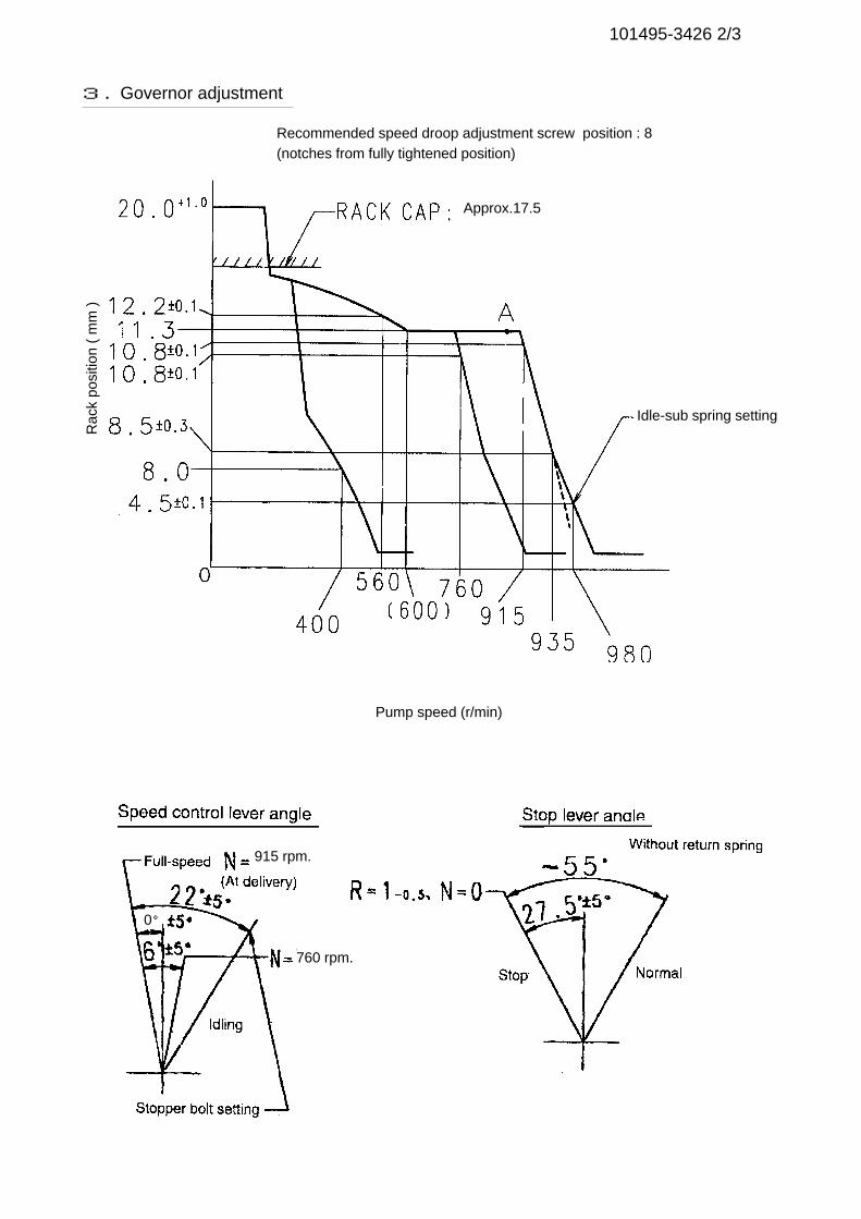
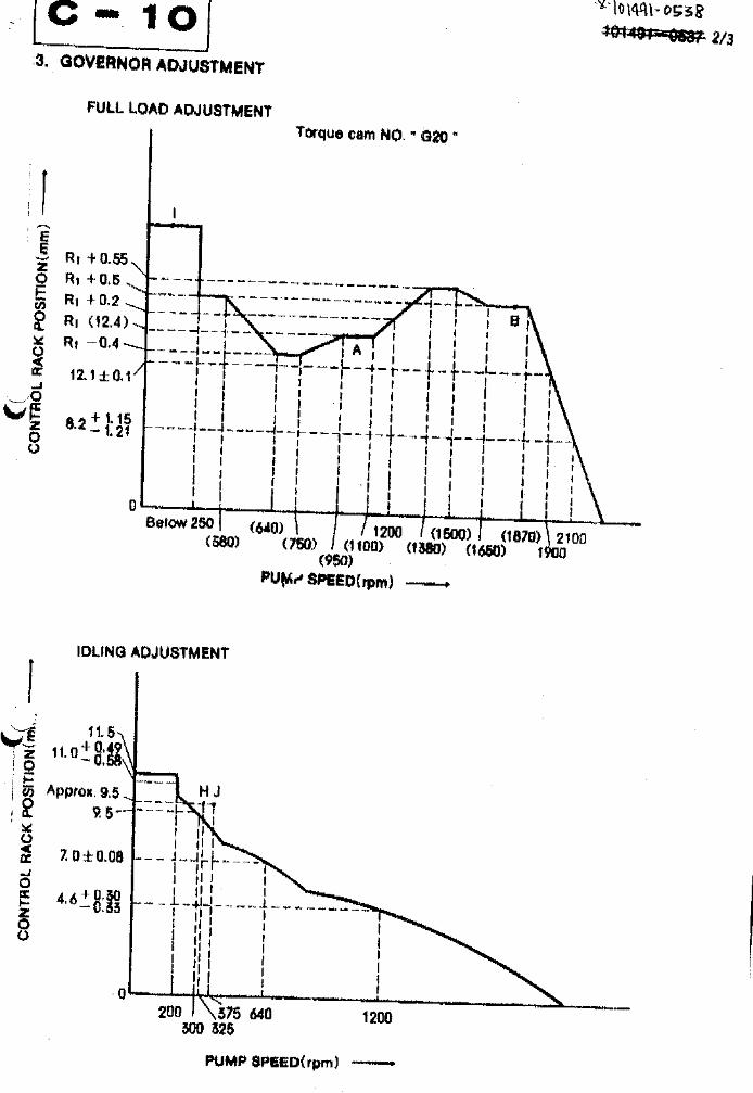
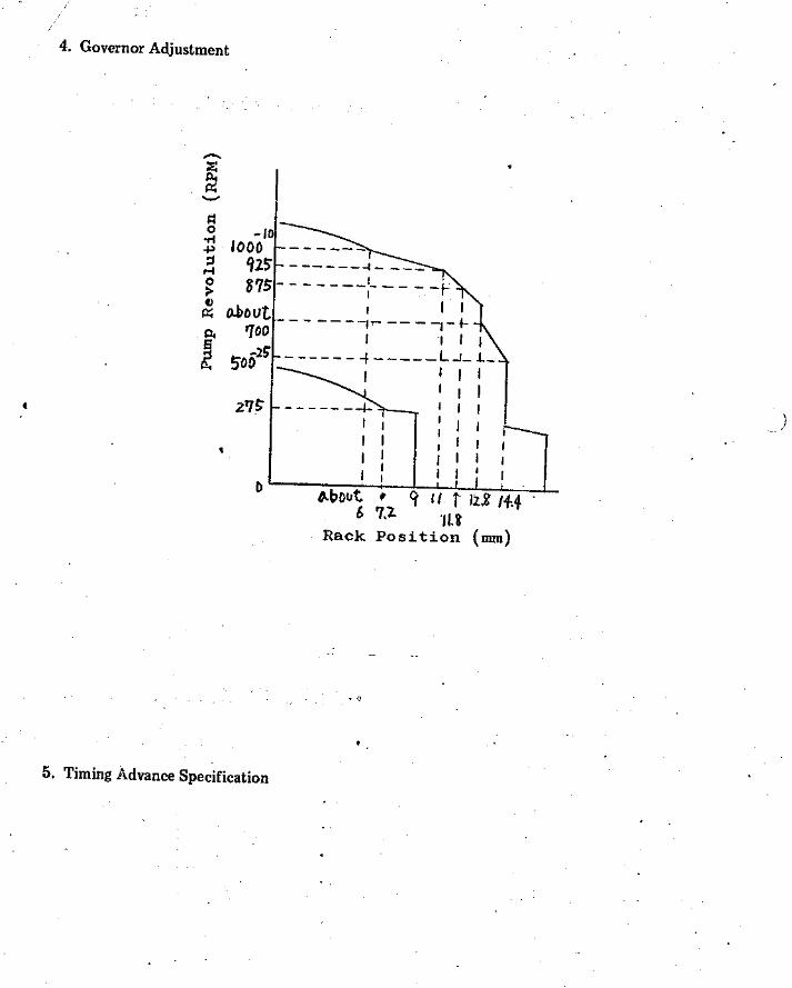
101495-3426 2/3
Pump speed (r/min)
Rac
k po
sitio
n (
mm
)3. Governor adjustment
Recommended speed droop adjustment screw position : 8(notches from fully tightened position)
Idle-sub spring setting
Approx.17.5
915 rpm.
0°
760 rpm.
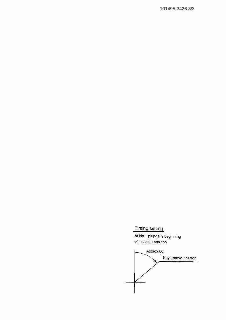
101495-3426 3/3
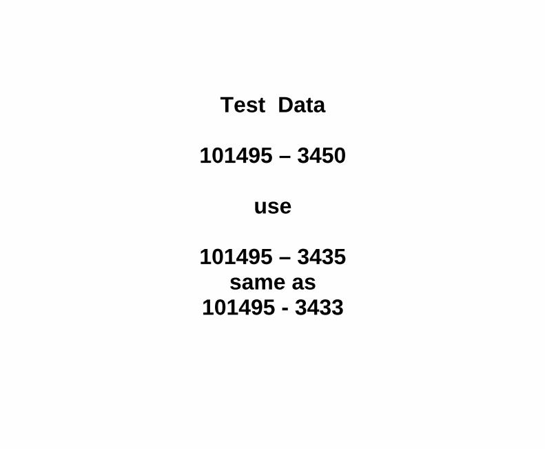
Test Data
101495 – 3450
use
101495 – 3435same as
101495 - 3433
Adjustingpoint
Rackposition
(mm)
Pumpspeed(r/min)
Injection q'ty(cm3 / 1000 strokes )
Max. variationbetween
cylinders (%)Fixed Remarks
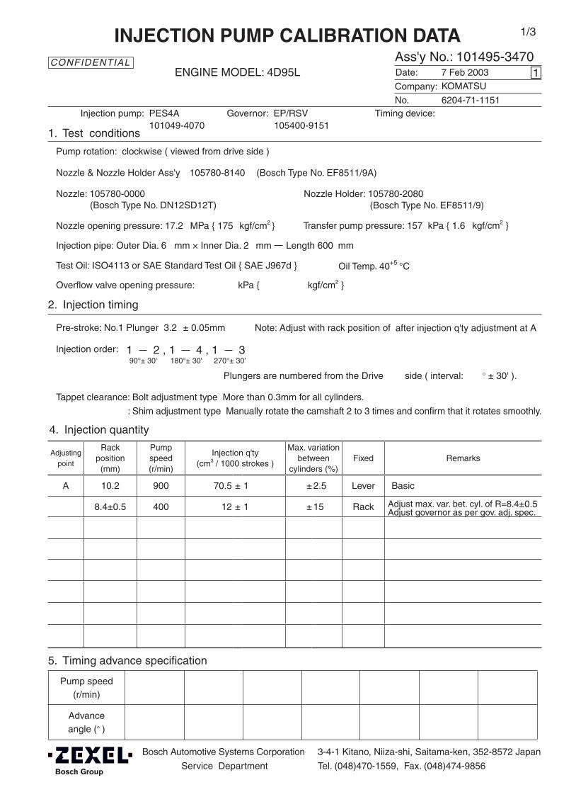
A 10.2 900 70.5 ± 1 ± 2.5 Lever Basic
8.4±0.5 400 12 ± 1 ± 15 Rack
Injection order: 1 2 , 1 4 , 1 390°± 30' 180°± 30' 270°± 30'
Pump speed(r/min)
Advanceangle (° )
4. Injection quantity
5. Timing advance specification
Bosch Automotive Systems Corporation
Service Department
3-4-1 Kitano, Niiza-shi, Saitama-ken, 352-8572 Japan
Tel. (048)470-1559, Fax. (048)474-9856
Company:
Ass'y No.: 101495-3470ENGINE MODEL: 4D95L
No. Governor: EP/RSV Timing device:
1. Test conditions
Date:
Pump rotation: clockwise ( viewed from drive side )
Injection pump: PES4A105400-9151
kgf/cm2 }
2. Injection timing
Pre-stroke: No.1 Plunger 3.2 ± 0.05mm
Plungers are numbered from the Drive ° ± 30' ).
Tappet clearance: Bolt adjustment type More than 0.3mm for all cylinders.
: Shim adjustment type Manually rotate the camshaft 2 to 3 times and confirm that it rotates smoothly.
CONFIDENTIAL
INJECTION PUMP CALIBRATION DATA
7 Feb 2003
6204-71-1151
101049-4070
Injection pipe: Outer Dia. 6 mm × Inner Dia. 2 mm Length 600 mm
Nozzle opening pressure: 17.2 MPa { 175 kgf/cm2 }
Nozzle: 105780-0000 Nozzle Holder: 105780-2080(Bosch Type No. DN12SD12T) (Bosch Type No. EF8511/9)
Nozzle & Nozzle Holder Ass'y: 105780-8140 (Bosch Type No. EF8511/9A)
Overflow valve opening pressure: kPa { kgf/cm2 }
Test Oil: ISO4113 or SAE Standard Test Oil { SAE J967d } Oil Temp. 40+5 °C
side ( interval:
1
Transfer pump pressure: 157 kPa { 1.6
Note: Adjust with rack position of
KOMATSU
1/3
Adjust max. var. bet. cyl. of R=8.4±0.5Adjust governor as per gov. adj. spec.
after injection q'ty adjustment at A
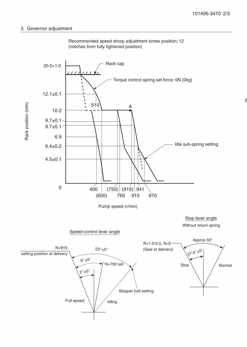
101495-3470 2/3
5. Timing advance specification
Adjust the clearance between the pickup and the gear tooth to 1-0.2mm.
3. Governor adjustment
10.2
0 400
A
Rac
k po
sitio
n (m
m)
Pump speed (r/min)
Recommended speed droop adjustment screw position: 12 (notches from fully tightened position)
20.0+1.0
12.1±0.1
9.7±0.1
6.4±0.2
(600)941
Idle sub-spring setting
Rack cap
9.7±0.1
6.9
4.5±0.1
(750)760
(910)915 970
510
Torque control spring set force: 0N {0kg}
N=760 set
23°±5°
Speed-control lever angle
Idling
Stopper bolt setting
N=915
setting position at delivery
Full-speed
6°±5°
2°±5°
Stop lever angle
Approx.55°
Stop Normal
27.5°±5°
R=1.0-0.5, N=0
(Seal at delivery)
Without return spring

101495-3470 3/3
58° ±3°
Timing setting
At No. 1 plunger’s beginning of injection position
Key groove position
After injection q'ty adjustment at A point
2°±30°
6. Load plunger equipped injection pump adjustment
(1) Confirm the plunger assembly stamping from the part catalogue.
(2) Temporarily insert a pre-stroke adjusting shim t mm into each cylinder and adjust the injection quantity
and the maximum variation between cylinders.
(3) At full load point A adjust the pre-stroke so that it is as specified.
(4) After adjusting the pre-stroke, reconfirm that the injection quantity and the maximum variation between
cylinders are as specified.
t mm 0.8
Mark an aligning mark on the pump housing(Width,depth 0.3 mm)


Adjustingpoint
Rackposition
(mm)
Pumpspeed(r/min)
Injection quantity(cm3/1000 strokes)
Max. variationbetween
cylinders (%)Fixed Remarks
12.5 850 91 ± 2 ± 3.5 Rack
H Approx 9.5 275 - Rack
A R1(12.5) 850 91 ± 1 - Lever
B 1450 (92) ± 2 - Lever
C R1+0.45 1160 (94.5) ± 2 - Lever
I - 100 160 + 10 - Lever Rack limit
F (R1-0.85) 580 (77) - Lever
G R1-1.05 435 (70.5) ± 2 - Lever
Oil temperature: 40+5 °C
BOSCH K.K.Sales Automotive Aftermarket Division
3-4-1 Kitano, Niiza-shi, Saitama-ken, 352-8572, JAPAN
Tel. 81-48-475-2521 Fax. 81-48-475-2520
Injection order:
4. Injection quantity
5. Timing advance specification
Company:
Assy No.: 101603-2361ENGINE MODEL: J-2
No. Governor: EP/RLD-F Timing device: EP/SPG
1. Test conditions
Date:
Pump rotation: counter clockwise (viewed from drive side)
Injection pump: PE6MD105932-2171 105680-5010
kgf/cm2}
2. Injection timing
Pre-stroke: No.1 plunger 3.8 ± 0.03mm mm
Plungers are numbered from the ° ± 30').
Tappet clearance: Bolt adjustment type - More than 0.3 mm for all cylinders.: Shim adjustment type - Manually rotate the camshaft 2 to 3 times and confirm that it rotates smoothly.
CONFIDENTIAL
INJECTION PUMP CALIBRATION DATA
29 Jun 2007
22000-9591A
101060-6170
Injection pipe: outer dia. 6 mm × inner dia. 2 mm length 600 mm
Test oil: ISO4113 or SAE standard test oil {SAE J967d}
side (interval:
0
Transfer pump pressure: 255 kPa {2.6
Note: Adjust with rack position of
Governor
1/3
Cylinder variation adjustment standardBasic
TEMPORARILY
1 4 , 1 2 , 1 6 , 1 3 , 1 560°± 15' 120°± 15' 180°± 15' 240°± 15' 300°± 15'
Overflow valve opening pressure: 255 ± 34 kPa {2.6 ± 0.35 kgf/cm2}
HINO
Nozzle opening pressure: 1st 16.7 MPa { 170 kgf/cm2 } 2nd 21.6 kgf/cm2 }MPa { 220
Each cylinder 13±1
+0.1-0.05[R1+0.8]
Nozzle: 105025-0360 Nozzle holder: 105030-3700(Bosch type no. ) (Bosch type no. )
Nozzle & nozzle holder assy: 105101-8160 (Bosch type no. )
Pump speed(r/min)
(Measure) (Measure) 1255 - 50 1420 - 50
Advanceangle (° )
Start
0 1.25 ± 0.3 1.25 ± 0.3
Finish
5.5±0.3
Cylinder variation adjustment standard
Basic
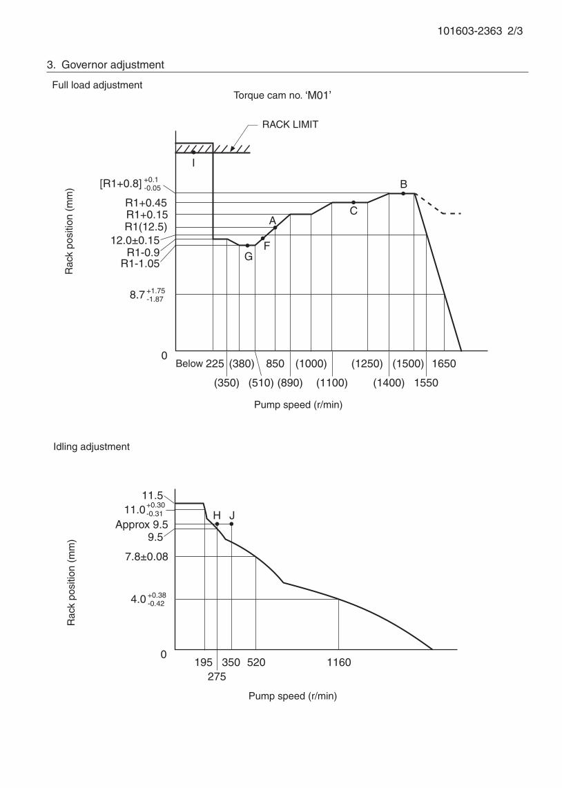
101603-2363 2/3
3. Governor adjustment
0195
275350 1160
Rac
k po
sitio
n (m
m)
Pump speed (r/min)
11.0+0.30-0.31
R1(12.5)R1+0.15
0Below 225 (380)
A
B
Rac
k po
sitio
n (m
m)
Pump speed (r/min)
Torque cam no. ‘M01’
R1+0.45
(1000)
520
Approx 9.5
Full load adjustment
Idling adjustment
RACK LIMIT
R1-0.9
7.8±0.08
I
H J
F
C
8.7 +1.75-1.87
[R1+0.8] +0.1-0.05
R1-1.05
12.0±0.15
(350) (510)
850
(890) (1100)
(1250)
(1400)
(1500)
1550
1650
4.0 +0.38-0.42
9.5
11.5
G

101603-2363 3/3
R=17.8±0.2
Free
Timing setting
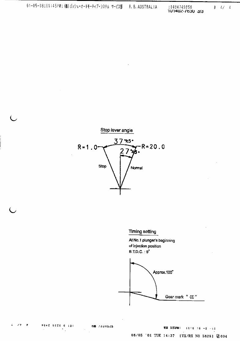
At No. 1 plunger’s beginning of injection position
(40°)
Stopper bolt H position
(Apply red paint after setting)
Stopper screw setting
Coupling key groove positionApprox.20°
40° ±3°
Speed-control lever angle
Idling
Full-speed
6° ±5°
Stop lever angle
33°±
5°
0°±5°
Stop
7°±5°
Normal
(Speed lever: full, N=100)

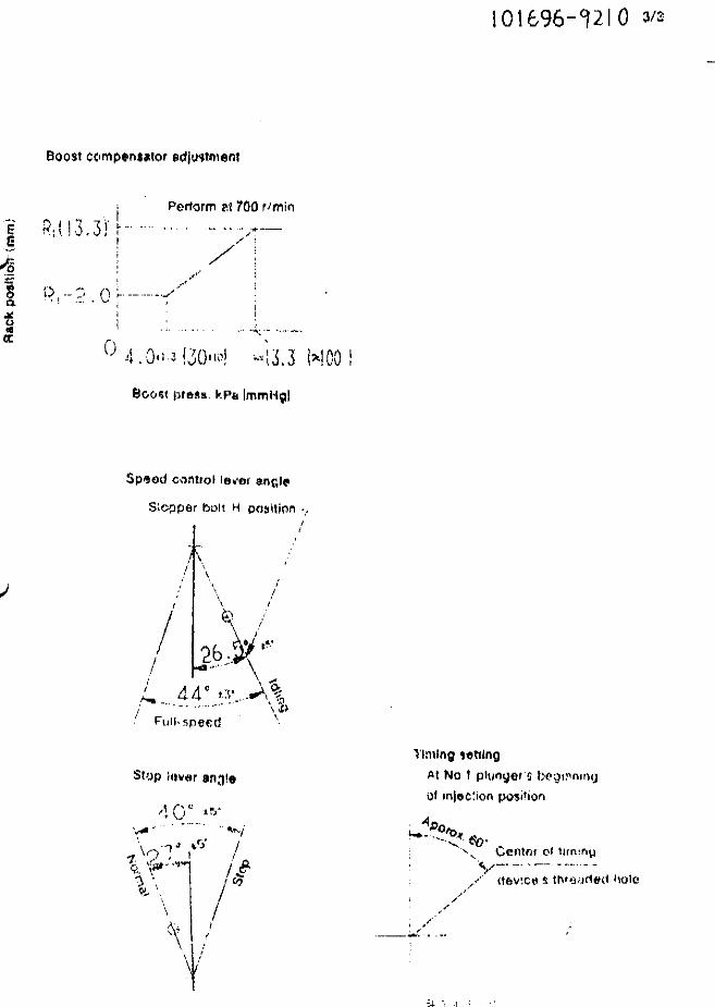
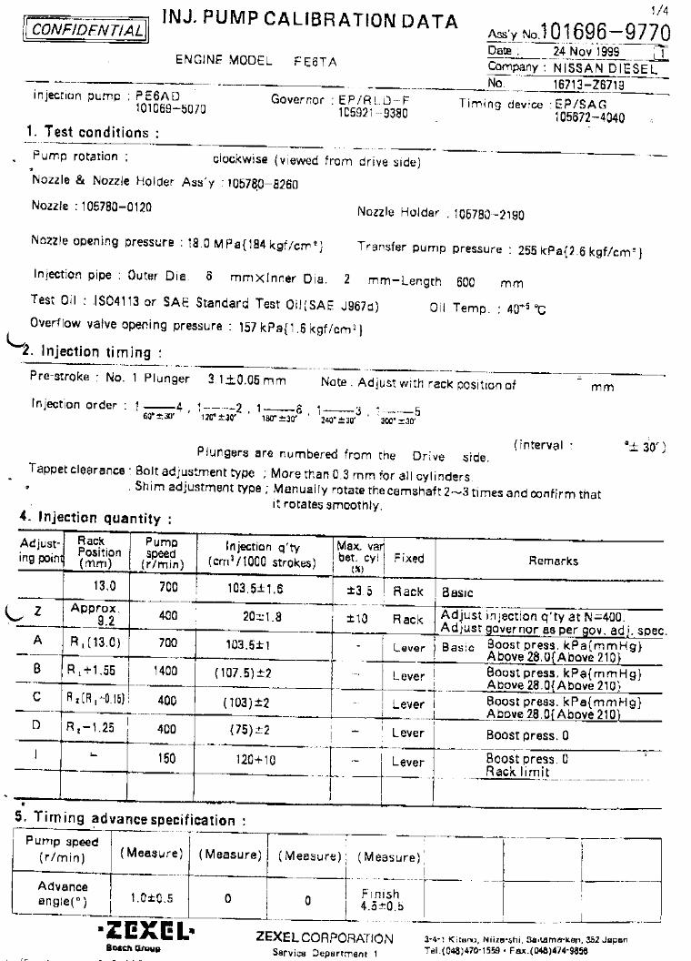
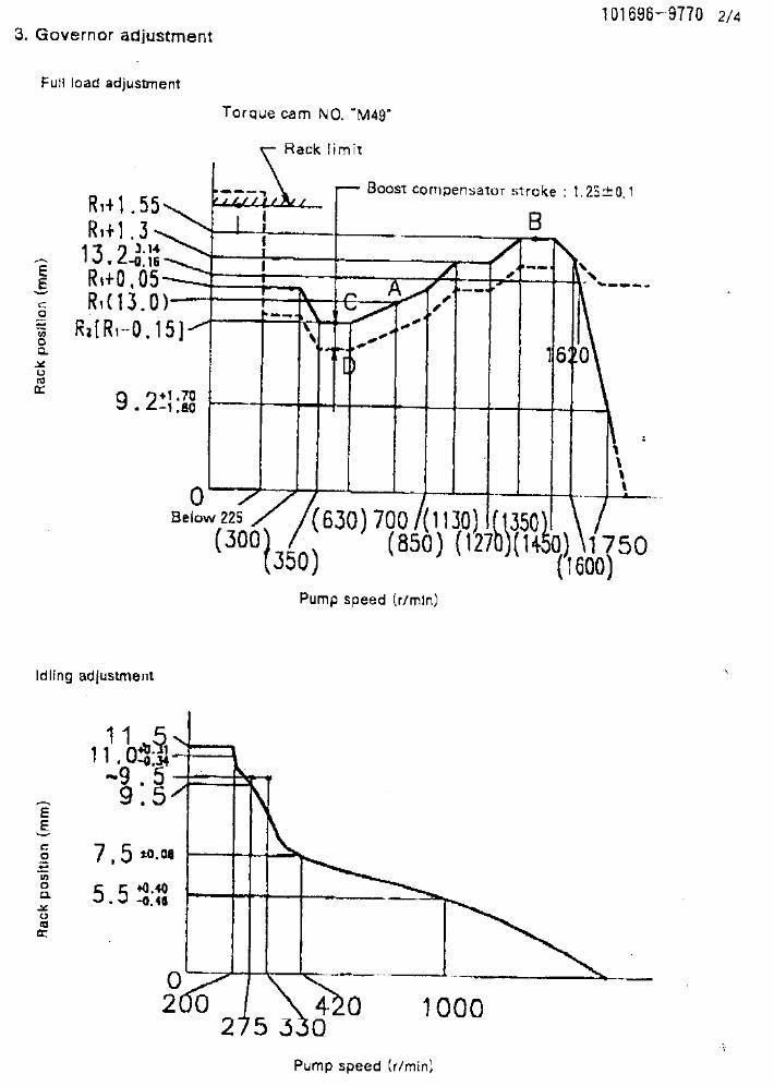
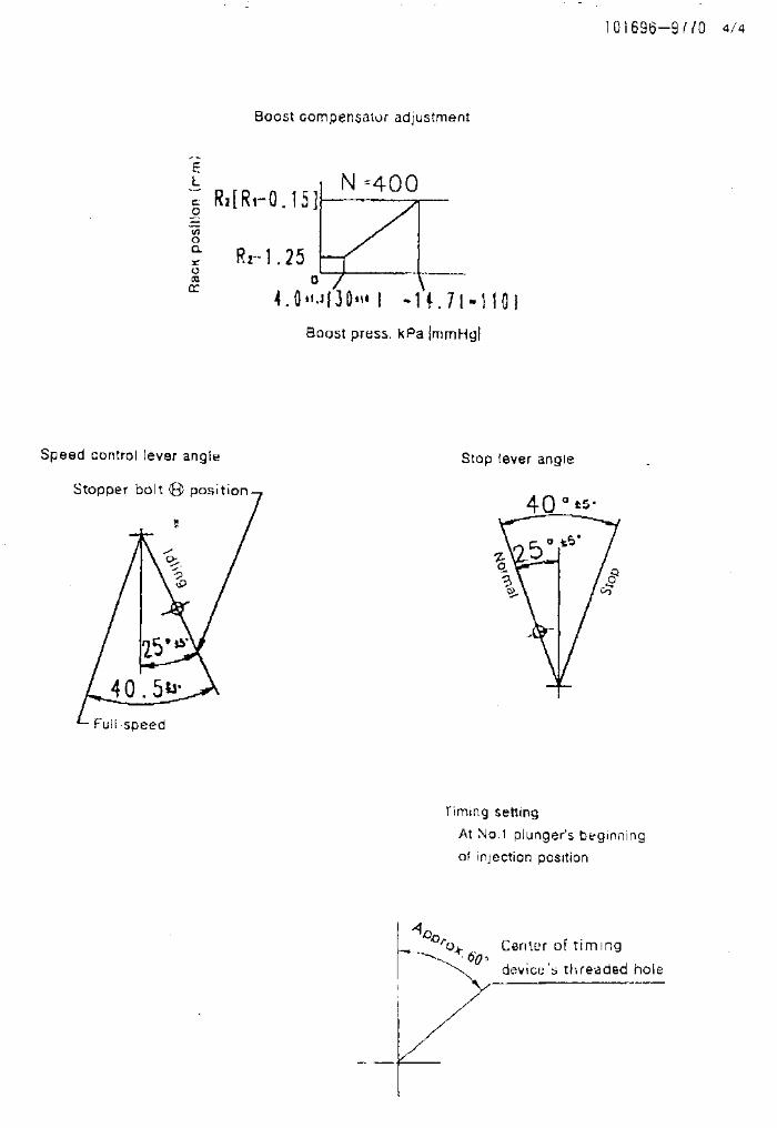
101603-8900 ZEXEL test values diesel fuel-injection equipment 12/11/08 13:19:56 Page 1
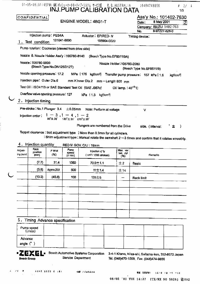
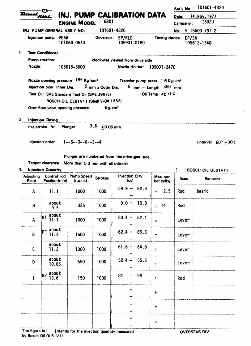
ZEXEL Ass'y No. 101603-8900Bosch Ass'y No. 9 400 610 684Bosch TypecodeEngine Type 6BG1-TManufacturer ISUZUEdition date 31/05/06 (1)
1 Adjustment conditionsCAT Designation Unit Set value min. max. Actual values OT
Test oil ISO4113 or {SAEJ967d}
1404 Test oilP Test Oil Temperature degC 40 40 45
Nozzle and nozzle holder 105780-8140Bosch type code EF8511/9ANozzle 105780-0000Bosch type code DN12SD12TNozzle holder 105780-2080Bosch type code EF8511/9
P Opening Pressure MPa 17.2P Opening Pressure kgf/cm2 175
Injection pipe mm 6-2-600Outer diameter - inner diameter - length (mm)
Overflow valve 131424-4920P Overflow valve opening pressure kPa 127 107 147P Overflow valve opening pressure kgf/cm2 1.3 1.1 1.5P Tester oil delivery pressure kPa 157 157 157P Tester oil delivery pressure kgf/cm2 1.6 1.6 1.6
Direction of rotation (viewed from drive side) RRight
2 Adjustment specification2.1 Injection timing adjustmentCAT Designation Unit Set value min. max. Actual values OT
P Direction of rotation (viewed from drive side) RRight
P Injection order 1-5-3-6-2-4S Pre-stroke mm 3.6 3.55 3.65P Beginning of injection position NO.1
Drive sideS Difference between angles 1 deg. 60 59.5 60.5
Cal 1-5S Difference between angles 2 deg. 120 119.5 120.5
Cal 1-3S Difference between angles 3 deg. 180 179.5 180.5
Cal 1-6S Difference between angles 4 deg. 240 239.5 240.5
Cyl.1-2S Difference between angles 5 deg. 300 299.5 300.5
Cal 1-42.2 Injection quantity adjustmentCAT Designation Unit Set value min. max. Actual values OT
P Adjusting point AP Rack position 10.9P Pump speed r/min 1100 1100 1100S Average injection quantity mm3/st. 98.5 97 100S Max variation between cylinders % 0 -2.5 2.5P Basic *P Fixing the lever *P Boost pressure kPa 66.7 66.7P Boost pressure mmHg 500 500
CAT Designation Unit Set value min. max. Actual values OTP Adjusting point CP Rack position 6.4+-0.5P Pump speed r/min 415 415 415S Average injection quantity mm3/st. 9 7.7 10.3S Max variation between cylinders % 0 -14 14P Fixing the rack *P Boost pressure kPa 0 0 0P Boost pressure mmHg 0 0 0
CAT Designation Unit Set value min. max. Actual values OTP Adjusting point EP Rack position -P Pump speed r/min 100 100 100S Average injection quantity mm3/st. 110 105 115
C = Check value)OT = Outside Tolerance (X is set)
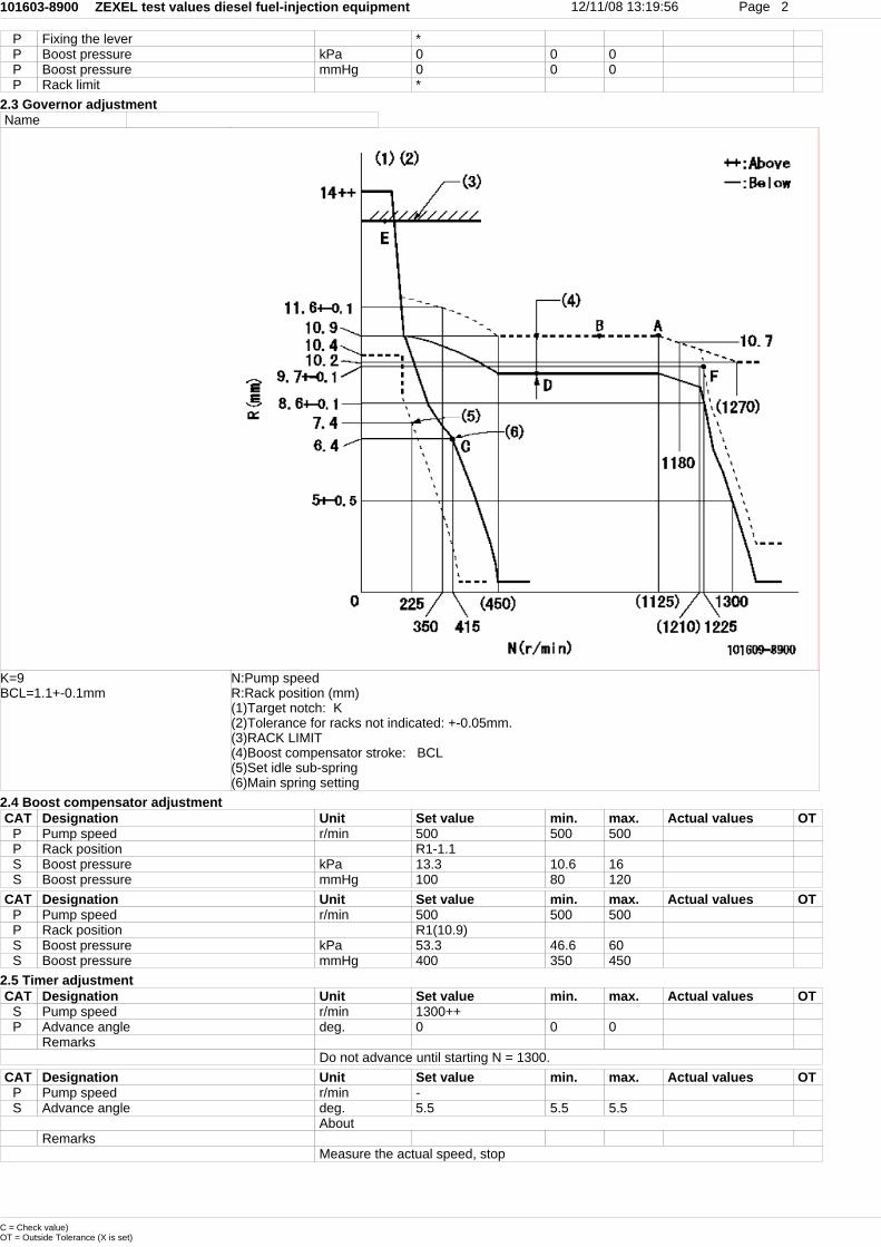
101603-8900 ZEXEL test values diesel fuel-injection equipment 12/11/08 13:19:56 Page 2
P Fixing the lever *P Boost pressure kPa 0 0 0P Boost pressure mmHg 0 0 0P Rack limit *
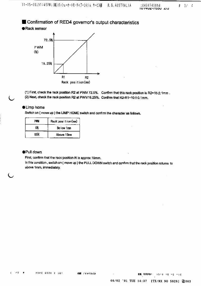
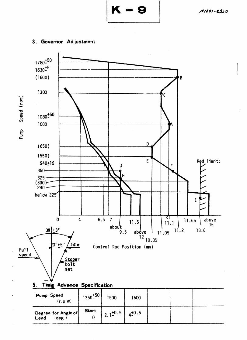
2.3 Governor adjustmentName
K=9BCL=1.1+-0.1mm
N:Pump speedR:Rack position (mm)(1)Target notch: K(2)Tolerance for racks not indicated: +-0.05mm.(3)RACK LIMIT(4)Boost compensator stroke: BCL(5)Set idle sub-spring(6)Main spring setting
2.4 Boost compensator adjustmentCAT Designation Unit Set value min. max. Actual values OT
P Pump speed r/min 500 500 500P Rack position R1-1.1S Boost pressure kPa 13.3 10.6 16S Boost pressure mmHg 100 80 120
CAT Designation Unit Set value min. max. Actual values OTP Pump speed r/min 500 500 500P Rack position R1(10.9)S Boost pressure kPa 53.3 46.6 60S Boost pressure mmHg 400 350 450
2.5 Timer adjustmentCAT Designation Unit Set value min. max. Actual values OT
S Pump speed r/min 1300++P Advance angle deg. 0 0 0
RemarksDo not advance until starting N = 1300.
CAT Designation Unit Set value min. max. Actual values OTP Pump speed r/min -S Advance angle deg. 5.5 5.5 5.5
AboutRemarks
Measure the actual speed, stop
C = Check value)OT = Outside Tolerance (X is set)

101603-8900 ZEXEL test values diesel fuel-injection equipment 12/11/08 13:19:56 Page 3
2.6 Speed control lever angleName
a=6deg+-5degb=23deg+-5deg
F:Full speedI:Idle(1)Stopper bolt setting
2.7 Stop lever angleName
a=32deg+-5degb=(55deg)
aa=0r/minbb=1-0.5mm
N:Pump normalS:Stop the pump.(1)Pump speed aa and rack position bb (to be sealed at delivery)
2.8 Timing settingName
a=(60deg)
aa=12deg (1)Pump vertical direction(2)Position of timer's threaded hole at No 1 cylinder's beginning of injection(3)B.T.D.C.: aa(4)-
C = Check value)OT = Outside Tolerance (X is set)
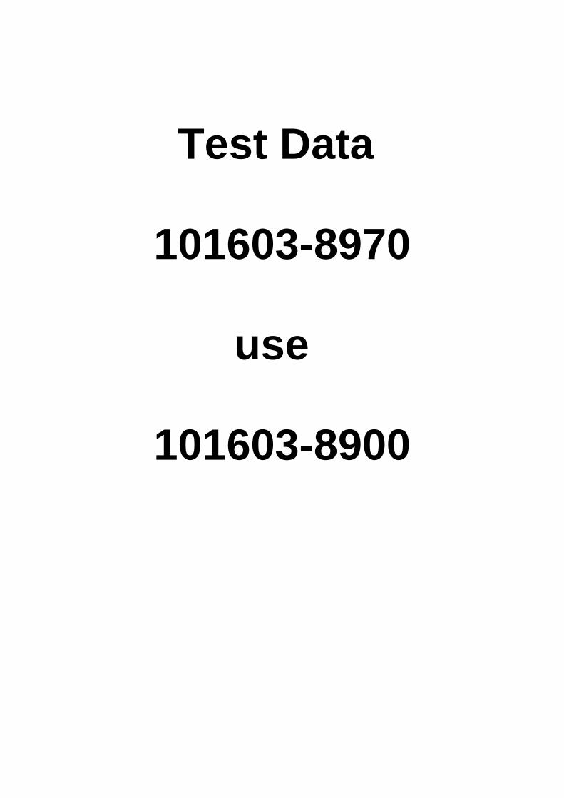
Test Data
101603-8970
use
101603-8900
Adjustingpoint
Rackposition
(mm)
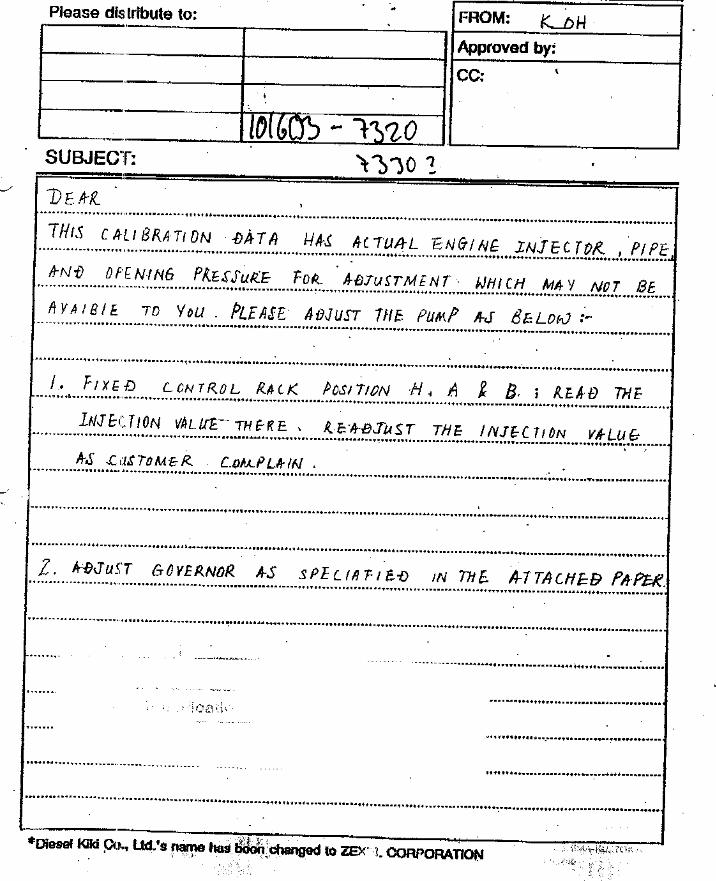
Pumpspeed(r/min)
Injection q'ty(cm3 / 1000 strokes )
Max. variationbetween
cylinders (%)Fixed Remarks
A 11.0 1075 110.5 ± 1.5 ± 2 Lever Basic
7.7±0.5 450 12 ± 1.3 ± 14 Rack
D Above. 11.2 100 105 ± 5 - Lever Rack limit
Injection order:
Pump speed(r/min)
Advanceangle (° )
4. Injection quantity
5. Timing advance specification
Bosch Automotive Systems Corporation
Service Department
3-4-1 Kitano, Niiza-shi, Saitama-ken, 352-8572 Japan
Tel. (048)470-1559, Fax. (048)474-9856
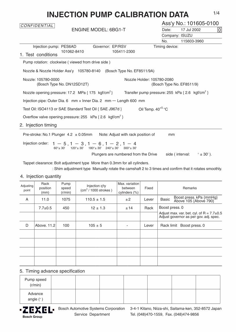
Company:
Ass'y No.: 101605-0100ENGINE MODEL: 6BG1-T
No. Governor: EP/RSV Timing device:
1. Test conditions
Date:
Pump rotation: clockwise ( viewed from drive side )
Injection pump: PES6AD105411-2300
kgf/cm2 }
2. Injection timing
Pre-stroke: No.1 Plunger 4.2 ± 0.05mm mm
Plungers are numbered from the Drive ° ± 30' ).
Tappet clearance: Bolt adjustment type More than 0.3mm for all cylinders.
: Shim adjustment type Manually rotate the camshaft 2 to 3 times and confirm that it rotates smoothly.
CONFIDENTIAL
INJECTION PUMP CALIBRATION DATA
17 Jul 2002
ISUZU
115603-3960
101062-8410
Injection pipe: Outer Dia. 6 mm × Inner Dia. 2 mm Length 600 mm
Nozzle opening pressure: 17.2 MPa { 175 kgf/cm2 }
Nozzle: 105780-0000 Nozzle Holder: 105780-2080(Bosch Type No. DN12SD12T) (Bosch Type No. EF8511/9)
Nozzle & Nozzle Holder Ass'y: 105780-8140 (Bosch Type No. EF8511/9A)
Overflow valve opening pressure: 255 kPa { 2.6 kgf/cm2 }
Test Oil: ISO4113 or SAE Standard Test Oil { SAE J967d } Oil Temp. 40+5 °C
side ( interval:
0
Transfer pump pressure: 255 kPa { 2.6
Note: Adjust with rack position of
1 5 , 1 3 , 1 6 , 1 2 , 1 460°± 30' 120°± 30' 180°± 30' 240°± 30' 300°± 30'
1/4
Boost press. 0
Adjust max. var. bet. cyl. of R = 7.7±0.5Adjust governor as per gov. adj. spec.
Boost press. kPa {mmHg}Above 105 {Above 790}
Boost press. 0
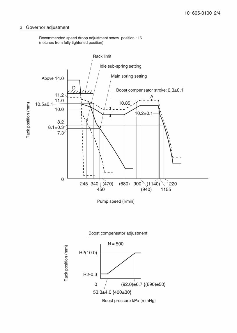
101605-0100 2/4
3. Governor adjustment
Recommended speed droop adjustment screw position : 16(notches from fully tightened position)
A
D
Pump speed (r/min)
12200
245450
340 900
Above 14.0
10.5±0.1
Rac
k po
sitio
n (m
m)
7.3
Rack limit
Idle sub-spring setting
Main spring setting
Boost compensator stroke: 0.3±0.1
1155(1140)
(940)(680)
11.2
8.1±0.3
10.85
R2(10.0)
R2-0.3
0
53.3±4.0 {400±30}
(92.0)±6.7 {(690)±50}
N = 500
Rac
k po
sitio
n (m
m)
Boost pressure kPa {mmHg}
Boost compensator adjustment
11.0
10.0
8.2
(470)
10.2±0.1
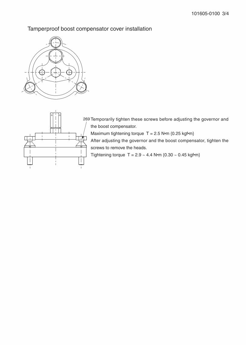
101605-0100 3/4
■ Tamperproof boost compensator cover installation
Temporarily tighten these screws before adjusting the governor and
the boost compensator.
Maximum tightening torque T = 2.5 N•m {0.25 kgf•m}
After adjusting the governor and the boost compensator, tighten the
screws to remove the heads.
Tightening torque T = 2.9 ~ 4.4 N•m {0.30 ~ 0.45 kgf•m}
269

101605-0100 4/4
Speed-control lever angle
Idling
Stopper bolt setting
Approx.55°
Stop lever angle
N=0, R=1.0-0.5
Stop
Full-speed
Normal
(20°) ±5°
(3°)±5°
50°±5°
Timing setting
At No. 1 plunger’s beginning of injection positionB.T.D.C.: 9°
Approx. 100°
Gear mark “CC”
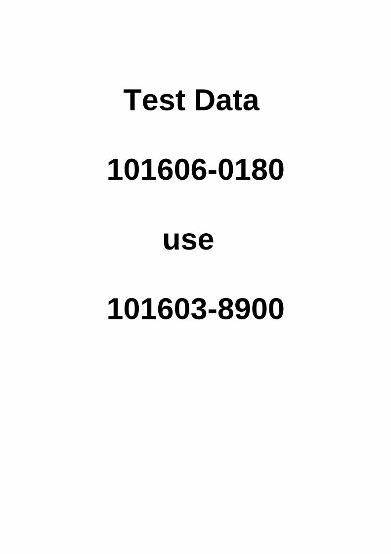
Test Data
101606-0180
use
101603-8900
Adjustingpoint
Rackposition
(mm)
Pumpspeed(r/min)
Injection quantity(cm3/1000 strokes)
Max. variationbetween
cylinders (%)Fixed Remarks
13.0 700 - Rack
H Approx 9.5 275 - Rack
A R1(13.0) 700 96.8 ± 1 - Lever
B R1-0.35 1400 (100.3) ± 2 - Lever
C R2-0.6 300 (66.9) ± 2 - Lever
D R2(R1+0.25) 500 (96.5) ± 2 - Lever
I - 100 95 ± 20 - Lever Rack limit
Oil temperature: 40+5 °C
BOSCH K.K.Sales Automotive Aftermarket Division
3-4-1 Kitano, Niiza-shi, Saitama-ken, 352-8572, JAPAN
Tel. 81-48-475-2521 Fax. 81-48-475-2520
Injection order:
4. Injection quantity
5. Timing advance specification
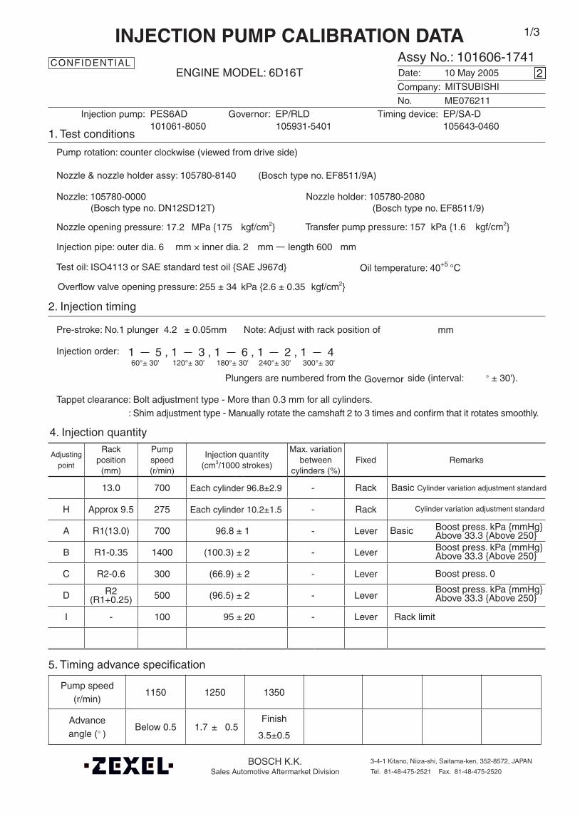
Company:
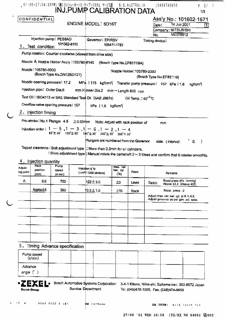
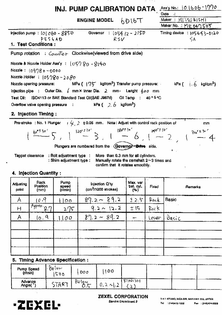
Assy No.: 101606-1741ENGINE MODEL: 6D16T
No. Governor: EP/RLD Timing device: EP/SA-D
1. Test conditions
Date:
Pump rotation: counter clockwise (viewed from drive side)
Injection pump: PES6AD105931-5401 105643-0460
kgf/cm2}
2. Injection timing
Pre-stroke: No.1 plunger 4.2 ± 0.05mm mm
Plungers are numbered from the ° ± 30').
Tappet clearance: Bolt adjustment type - More than 0.3 mm for all cylinders.: Shim adjustment type - Manually rotate the camshaft 2 to 3 times and confirm that it rotates smoothly.
CONFIDENTIAL
INJECTION PUMP CALIBRATION DATA
10 May 2005
ME076211
101061-8050
Injection pipe: outer dia. 6 mm × inner dia. 2 mm length 600 mm
Nozzle opening pressure: 17.2 MPa {175 kgf/cm2}
Test oil: ISO4113 or SAE standard test oil {SAE J967d}
side (interval:
2
Transfer pump pressure: 157 kPa {1.6
Note: Adjust with rack position of
1 5 , 1 3 , 1 6 , 1 2 , 1 460°± 30' 120°± 30' 180°± 30' 240°± 30' 300°± 30'
Governor
1/3
Boost press. kPa {mmHg}Above 33.3 {Above 250}
Boost press. 0
Cylinder variation adjustment standard
Basic
Overflow valve opening pressure: 255 ± 34 kPa {2.6 ± 0.35 kgf/cm2}
MITSUBISHI
Each cylinder 10.2±1.5
Nozzle: 105780-0000 Nozzle holder: 105780-2080(Bosch type no. DN12SD12T) (Bosch type no. EF8511/9)
Nozzle & nozzle holder assy: 105780-8140 (Bosch type no. EF8511/9A)
Pump speed(r/min)
1150 1250 1350
Advanceangle (° )
Below 0.5 1.7 ± 0.5 Finish
3.5±0.5
Each cylinder 96.8±2.9 Basic
Cylinder variation adjustment standard
Boost press. kPa {mmHg}Above 33.3 {Above 250}
Boost press. kPa {mmHg}Above 33.3 {Above 250}

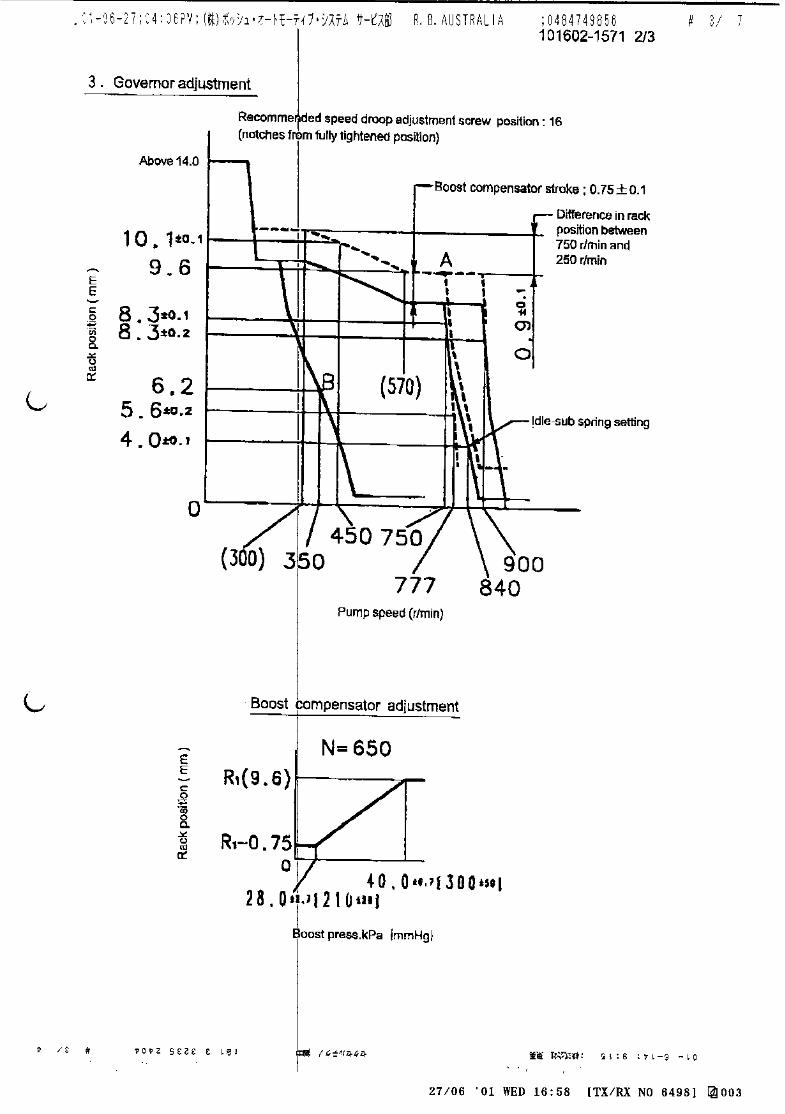
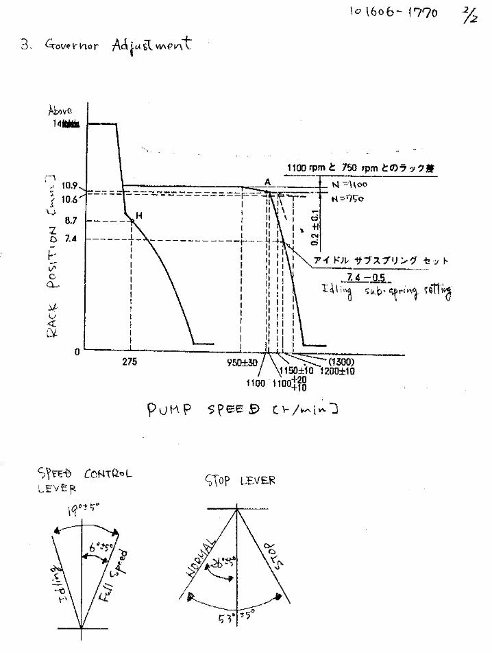
101606-1741 2/3
3. Governor adjustment
0200±5
275 350
1000±70
Rac
k po
sitio
n (m
m)
Pump speed (r/min)
11.5
R1(13.0)
0Below 225 (600)
(1300)
A
B
Rac
k po
sitio
n (m
m)
Pump speed (r/min)
Torque cam no. ‘D24’
R1+0.25
700
(900) (1150)
650±15
Full load adjustment
Idling adjustment
R1-0.05
R1-0.35
8.7
(750)
I
H J
C
(1050)
Boost compensator stroke: 0.6±0.1
Rack limit
1600±50
1500±5
10.8
4.4
6.2
Approx 9.59.5
R2(R1+0.25)
R2-0.6
0
6.0±1.3 {45±10}
(20.0) {(150)}
N = 450
Rac
k po
sitio
n (m
m)
Boost pressure kPa {mmHg}
Boost compensator adjustment
R1-0.15
R1-0.85
D
(1480)
Microswitch adjustmentAdjust the bolt so that the microswitch operates at a control lever position of R = 9.2mm and a pump speed of N=400±5 r/min.
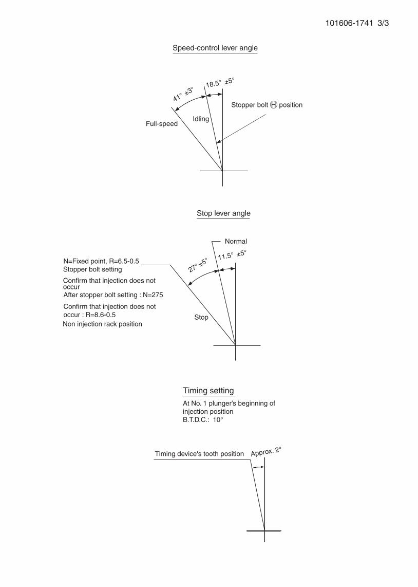
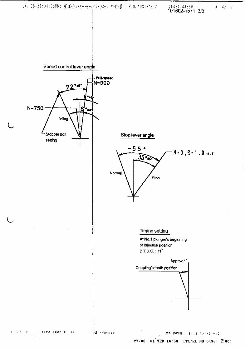
101606-1741 3/3
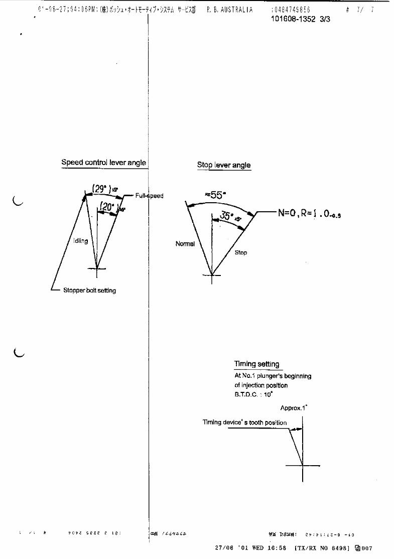
Stopper bolt setting
Timing device's tooth position Approx. 2°
Timing setting
At No. 1 plunger’s beginning of injection positionB.T.D.C.: 10°
N=Fixed point, R=6.5-0.5
Stopper bolt H position 41° ±3°
Speed-control lever angle
IdlingFull-speed
18.5° ±5°
Stop lever angle
Stop
Normal
11.5° ±5°
27°±5°
After stopper bolt setting : N=275
Confirm that injection does not occur
Confirm that injection does not occur : R=8.6-0.5Non injection rack position
Adjustingpoint
Rackposition
(mm)
Pumpspeed(r/min)
Injection quantity(cm3/1000 strokes)
Max. variationbetween
cylinders (%)Fixed Remarks
11.2 850 - Rack
H approx 9.5 275 - Rack
A R1(11.2) 850 57.7 ± 1 - Lever
B R1+0.1 1450 (72.6) ± 2 - Lever
C R1+0.8 500 (59.7) ± 2 - Lever
D R1+1.25 300 (57.1) ± 2 - Lever
I - 100 140 ± 10 - Lever Rack limit
Oil temperature: 40+5 °C
Injection order:
4. Injection quantity
7. Timing advance specification
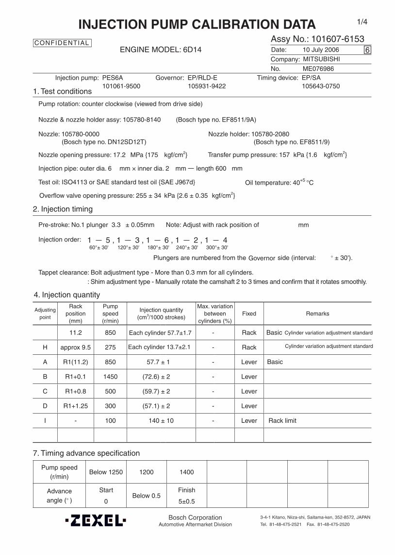
Company:
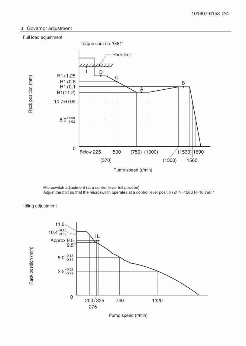
Assy No.: 101607-6153ENGINE MODEL: 6D14
No. Governor: EP/RLD-E Timing device: EP/SA
1. Test conditions
Date:
Pump rotation: counter clockwise (viewed from drive side)
Injection pump: PES6A105931-9422 105643-0750
kgf/cm2}
2. Injection timing
Pre-stroke: No.1 plunger 3.3 ± 0.05mm mm
Plungers are numbered from the ° ± 30').
Tappet clearance: Bolt adjustment type - More than 0.3 mm for all cylinders.: Shim adjustment type - Manually rotate the camshaft 2 to 3 times and confirm that it rotates smoothly.
CONFIDENTIAL
INJECTION PUMP CALIBRATION DATA
10 July 2006
ME076986
101061-9500
Injection pipe: outer dia. 6 mm × inner dia. 2 mm length 600 mm
Nozzle opening pressure: 17.2 MPa {175 kgf/cm2}
Test oil: ISO4113 or SAE standard test oil {SAE J967d}
side (interval:
6
Transfer pump pressure: 157 kPa {1.6
Note: Adjust with rack position of
1 5 , 1 3 , 1 6 , 1 2 , 1 460°± 30' 120°± 30' 180°± 30' 240°± 30' 300°± 30'
Governor
1/4
Cylinder variation adjustment standard
Basic
Overflow valve opening pressure: 255 ± 34 kPa {2.6 ± 0.35 kgf/cm2}
MITSUBISHI
Each cylinder 57.7±1.7
Nozzle: 105780-0000 Nozzle holder: 105780-2080(Bosch type no. DN12SD12T) (Bosch type no. EF8511/9)
Nozzle & nozzle holder assy: 105780-8140 (Bosch type no. EF8511/9A)
Pump speed(r/min)
Below 1250 1200 1400
Advanceangle (° )
Start
0 Below 0.5
Finish
5±0.5
Bosch CorporationAutomotive Aftermarket Division
3-4-1 Kitano, Niiza-shi, Saitama-ken, 352-8572, JAPAN
Tel. 81-48-475-2521 Fax. 81-48-475-2520
Each cylinder 13.7±2.1 Cylinder variation adjustment standard
Basic
101607-6153 2/4
3. Governor adjustment
0200
275325 1320
Rac
k po
sitio
n (m
m)
Pump speed (r/min)
11.5
10.4+0.10-0.09
R1(11.2)
R1+0.8
0Below 225 500
(1300)
AB
Rac
k po
sitio
n (m
m)
Pump speed (r/min)
Torque cam no. ‘G81’
R1+1.25
R1+0.1
(370)
(750)
740
9.5Approx 9.5
Full load adjustment
Idling adjustment
Rack limit
I
(1000)
HJ
DC
8.0+1.08-1.02
10.7±0.09
(1530)
1560
1690
5.0+0.12-0.11
2.5+0.32-0.29
Microswitch adjustment (at a control lever full position)Adjust the bolt so that the microswitch operates at a control lever position of N=1560,R=10.7±0.1

101607-6153 3/4
5. Load sensor adjustment
[1] Measurement circuit
1 (black)
2 (yellow)
3 (red) (black)
(yellow)
(red)
Output voltage
Trimmer1k
Supply voltage: 3.57±0.02 V
[2] Adjustment(1) With the load lever contacting the FULL side, turn the shaft until the voltage between 1 and 2 is Vf (V).
(2) With the load lever contacting the IDLE side, adjust the trimmer until the voltage between 1 and 2 is Vi
(V).
Load lever
Trimmer
Nuts
Shaft
Vf (V) 3.0+0.05 At full
Vi (V) 1.0+0.1 At idle
(3) Repeat the above adjustments until the specifications are satisfied, and then tighten the nuts.
Specified torque: 3.4 ~ 4.9 N•m {0.35 ~ 0.5 kgf•m}

101607-6153 4/4
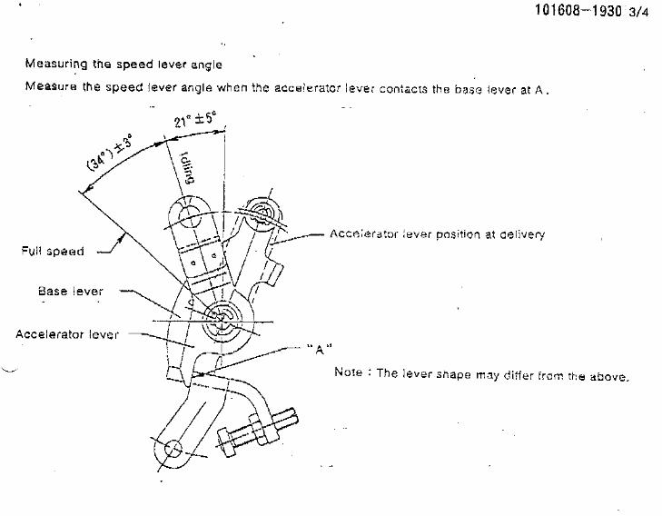
6. Measuring the speed lever angle
Measure the speed lever angle when the accelerator lever contacts the base lever at A.
Full speed
Base lever
Accelerator lever
A
(39°) ±3°
18.5°±5°
Accelerator lever position at delivery
Idling
Timing device's tooth positionApprox. 0°
Timing setting
At No. 1 plunger’s beginning of injection positionB.T.D.C.: 13°
Speed-control lever angle
Idling
Full-speed
18.5°±5°
(39°
)±3°
Stopper bolt H position
Free(25°)
36.5°±5°
Stop lever angle
(At delivery)
Normal
Stop
17°±5°
R=(16.8)
N=1550, R=7.0-0.5Stopper bolt setting
Confirm that injection does not occurAfter stopper bolt setting N=275Confirm that injection does not occu R=(Measure)Non injection rack position

Oil temperature: 40+5 °C
BOSCH K.K.Sales Automotive Aftermarket Division
3-4-1 Kitano, Niiza-shi, Saitama-ken, 352-8572, JAPAN
Tel. 81-48-475-2521 Fax. 81-48-475-2520
Adjustingpoint
Rackposition
(mm)
Pumpspeed(r/min)
Injection quantity(cm3/1000 strokes)
Max. variationbetween
cylinders (%)Fixed Remarks
A 10.0 1400 88.9 ± 1 ± 2.5 Lever Basic
B 10.0 800 (83.5) - Lever
C Approx 7.8 340 9.2 ± 1.5 ± 15 Rack
F (10.7) 100 (65) - Lever
Injection order:
Pump speed(r/min)
Below 1050 1000 1400
Advanceangle (° )
Start
0 Below 0.5
Finish
2±0.5
4. Injection quantity
5. Timing advance specification
Company:
Assy No.: 101607-6390ENGINE MODEL: 6D14T
No. Governor: EP/RFD-D Timing device: EP/SA-D
1. Test conditions
Date:
Pump rotation: counter clockwise (viewed from drive side)
Injection pump: PES6A105490-5720 105643-0450
kgf/cm2}
2. Injection timing
Pre-stroke: No.1 plunger 3.0 ± 0.05mm mm
Plungers are numbered from the ° ± 30').
Tappet clearance: Bolt adjustment type - More than 0.3 mm for all cylinders.: Shim adjustment type - Manually rotate the camshaft 2 to 3 times and confirm that it rotates smoothly.
CONFIDENTIAL
INJECTION PUMP CALIBRATION DATA
25 May 2004
ME046025
101061-9790
Injection pipe: outer dia. 6 mm × inner dia. 2 mm length 600 mm
Nozzle opening pressure: 17.2 MPa {175 kgf/cm2}
Nozzle: 105780-0000 Nozzle holder: 105780-2080(Bosch type no. DN12SD12T) (Bosch type no. EF8511/9)
Nozzle & nozzle holder assy: 105780-8140 (Bosch type no. EF8511/9A)
Test oil: ISO4113 or SAE standard test oil {SAE J967d}
side (interval:
1
Transfer pump pressure: 157 kPa {1.6
Note: Adjust with rack position of
1 5 , 1 3 , 1 6 , 1 2 , 1 460°± 30' 120°± 30' 180°± 30' 240°± 30' 300°± 30'
MITSUBISHI
Governor
1/3
Overflow valve opening pressure: 255 ± 34 kPa {2.6 ± 0.35 kgf/cm2}
After setting excessive fuel for starting
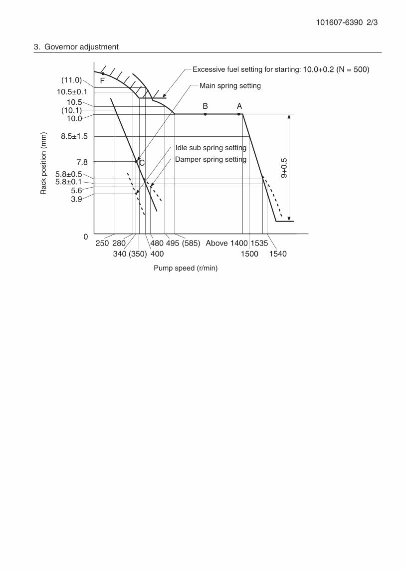
101607-6390 2/3
3. Governor adjustment
A
C
B
F
7.8
0250
9+0.
5
Rac
k po
sitio
n (m
m)
Pump speed (r/min)
Excessive fuel setting for starting: 10.0+0.2 (N = 500)
Damper spring setting
Main spring setting
Idle sub spring setting
(11.0)
10.5±0.110.5
(10.1)10.0
8.5±1.5
5.8±0.55.8±0.1
5.63.9
280340 (350)
(585)495480400
Above 14001500
15351540
101607-6390 3/3
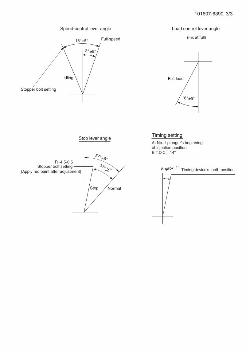
16°±5°
Stopper bolt setting
Stop lever angle
R=4.5-0.5
Stop
(Fix at full)
Normal
Timing setting
At No. 1 plunger’s beginning of injection positionB.T.D.C.: 14°
Full-load
Timing device's tooth position
Speed-control lever angle
Idling
Stopper bolt setting
Full-speed 18°±5°
3° ±5°
Approx. 1°
Load control lever angle
57°±5°57°
-5°+7°(Apply red paint after adjustment)
101608-1486 ZEXEL test values diesel fuel-injection equipment 07/05/03 11:17:29 Page 1
ZEXEL Ass'y No. 101608-1486
Bosch Ass'y No.
Bosch Typecode
Engine Type
Manufacturer
Edition date 27/09/00 (10)
1 Adjustment conditions
CAT Designation Unit Set value min. max. Actual values OT
Test oil ISO4113 or {SAEJ967d}
...
P Test Oil Temperature degC 40 40 45
Nozzle and nozzle holder 1005780-8260
Bosch type code 9 430 610 133
Nozzle 105780-0120
Bosch type code 1 688 901 990
Nozzle holder 105780-2190
P Opening Pressure MPa 18.0
P Opening Pressure kgf/cm2 184
Iinjection Pipe mm 6-2-600
Outer diameter - inner diameter - length (mm)
Overflow valve 131424-8420
P Overflow valve opening pressure kPa 255 255 255
P Overflow valve opening pressure kgf/cm2 2.6 2.6 2.6
P Tester oil delivery pressure kPa 255 255 255
P Tester oil delivery pressure kgf/cm2 2.6 2.6 2.6
Direction of rotation (viewed from drive side) L
Left
2 Adjustment specification
2.1 Injection timing adjustment
CAT Designation Unit Set value min. max. Actual values OT
P Direction of rotation (viewed from drive side) L
Left
P Injection order 1-5-3-6-2-4
S Pre-stroke mm 3.2 3.15 3.25
P Beginning of injection position No.1
Governor side
S Difference between angles 1 deg. 60 59.5 60.5
Cyl 1-5
S Difference between angles 2 deg. 120 119.5 120.5
Cyl 1-3
S Difference between angles 3 deg. 180 179.5 180.5
Cyl 1-6
S Difference between angles 4 deg. 240 239.5 240.5
Cyl.1-2
S Difference between angles 5 deg. 300 299.5 300.5
Cyl 1-4
2.2 Injection quantity adjustment
CAT Designation Unit Set value min. max. Actual values OT
P Adjusting point -
S = Setting value, C = Check value)OT = Outside Tolerance (X is set)

101608-1486 ZEXEL test values diesel fuel-injection equipment 07/05/03 11:17:29 Page 2
P Rack position 12.1
P Pump speed r/min 700 700 700
S Each cylinder's injection q'ty mm3/st. 110 106.7 113.3
P Basic *
P Fixing the rack *
P Standard for adjustment of the maximum variation between cylinders
*
CAT Designation Unit Set value min. max. Actual values OT
P Adjusting point Z
P Rack position 9.5+-0.5
P Pump speed r/min 275 275 275
S Each cylinder's injection q'ty mm3/st. 12.5 10.6 14.4
P Fixing the rack *
P Standard for adjustment of the maximum variation between cylinders
*
CAT Designation Unit Set value min. max. Actual values OT
P Adjusting point A
P Rack position R1(12.1)
P Pump speed r/min 700 700 700
S Average injection quantity mm3/st. 110 109 111
P Basic *
P Fixing the lever *
P Boost pressure kPa 23.3 23.3
P Boost pressure mmHg 175 175
CAT Designation Unit Set value min. max. Actual values OT
P Adjusting point B
P Rack position R1+1.0
P Pump speed r/min 1400 1400 1400
S Average injection quantity mm3/st. 114.5 110.5 118.5
P Fixing the lever *
P Boost pressure kPa 23.3 23.3
P Boost pressure mmHg 175 175
CAT Designation Unit Set value min. max. Actual values OT
P Adjusting point C
P Rack position R2(R1-0.4)
P Pump speed r/min 500 500 500
S Average injection quantity mm3/st. 108.5 104.5 112.5
P Fixing the lever *
P Boost pressure kPa 23.3 23.3
P Boost pressure mmHg 175 175
CAT Designation Unit Set value min. max. Actual values OT
P Adjusting point D
P Rack position R2-0.35
P Pump speed r/min 400 400 400
S Average injection quantity mm3/st. 95 91 99
P Fixing the lever *
P Boost pressure kPa 0 0 0
P Boost pressure mmHg 0 0 0
CAT Designation Unit Set value min. max. Actual values OT
P Adjusting point I
P Rack position (R1+1.7)
P Pump speed r/min 100 100 100
S = Setting value, C = Check value)OT = Outside Tolerance (X is set)

101608-1486 ZEXEL test values diesel fuel-injection equipment 07/05/03 11:17:29 Page 3
S Average injection quantity mm3/st. 160 160 160
P Fixing the lever *
P Boost pressure kPa 0 0 0
P Boost pressure mmHg 0 0 0
CAT Designation Unit Set value min. max. Actual values OT
P Adjusting point E
P Rack position (R1+0.4)
P Pump speed r/min 1100 1100 1100
S Average injection quantity mm3/st. 108.5 104.5 112.5
P Fixing the lever *
P Boost pressure kPa 23.3 23.3
P Boost pressure mmHg 175 175
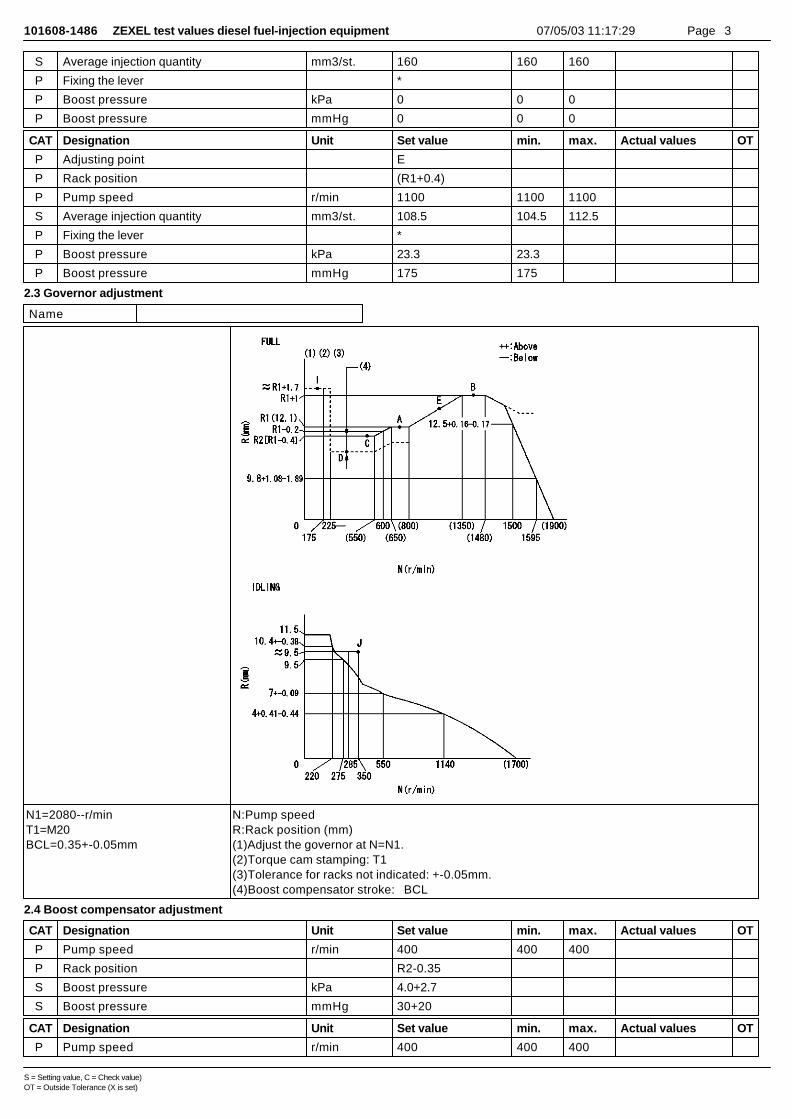
2.3 Governor adjustment
Name
N1=2080--r/minT1=M20BCL=0.35+-0.05mm
N:Pump speedR:Rack position (mm)(1)Adjust the governor at N=N1.(2)Torque cam stamping: T1(3)Tolerance for racks not indicated: +-0.05mm.(4)Boost compensator stroke: BCL
2.4 Boost compensator adjustment
CAT Designation Unit Set value min. max. Actual values OT
P Pump speed r/min 400 400 400
P Rack position R2-0.35
S Boost pressure kPa 4.0+2.7
S Boost pressure mmHg 30+20
CAT Designation Unit Set value min. max. Actual values OT
P Pump speed r/min 400 400 400
S = Setting value, C = Check value)OT = Outside Tolerance (X is set)
101608-1486 ZEXEL test values diesel fuel-injection equipment 07/05/03 11:17:29 Page 4
P Rack position R2(R1-0.4)
S Boost pressure kPa (10.0)
S Boost pressure mmHg (75)
2.5 Timer adjustment
CAT Designation Unit Set value min. max. Actual values OT
S Pump speed r/min 1000--
P Advance angle deg. 0 0 0
Remarks
Start
CAT Designation Unit Set value min. max. Actual values OT
P Pump speed r/min 950
S Advance angle deg. 0.5 0.5
CAT Designation Unit Set value min. max. Actual values OT
P Pump speed r/min 1400
S Advance angle deg. 3.5 3 4
Remarks
Finish
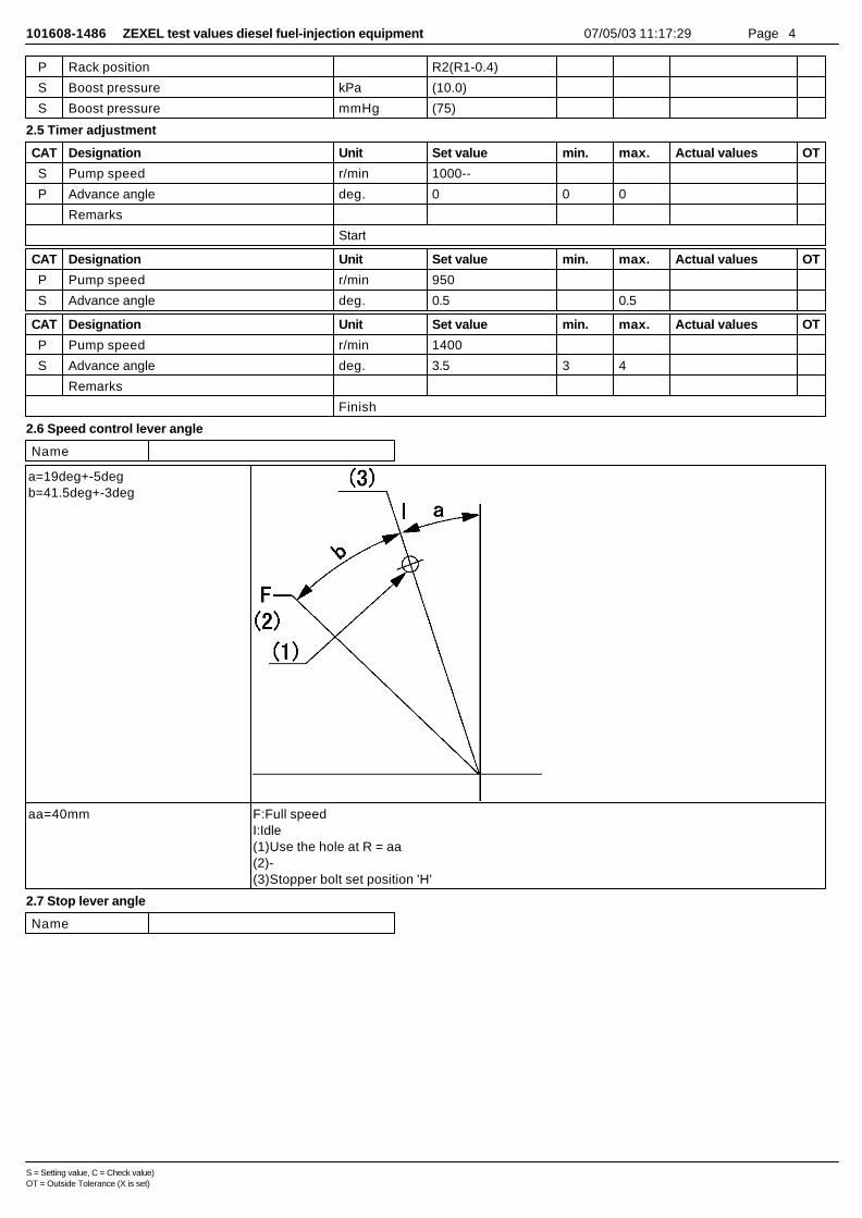
2.6 Speed control lever angle
Name
a=19deg+-5degb=41.5deg+-3deg
aa=40mm F:Full speedI:Idle(1)Use the hole at R = aa(2)-(3)Stopper bolt set position 'H'
2.7 Stop lever angle
Name
S = Setting value, C = Check value)OT = Outside Tolerance (X is set)

101608-1486 ZEXEL test values diesel fuel-injection equipment 07/05/03 11:17:29 Page 5
a=11.5deg+-5degb=28deg+-5deg
aa=1400r/minbb=7.0-0.5mmcc=285r/mindd=(8.4)mm
N:Pump normalS:Stop the pump.(1)After setting the stopper bolt so that the speed lever is in the full position, confirm that there isno injection at pump speed aa and rack position bb.(2)After setting the stopper bolt at the speed lever's idle position, confirm that there is no injection at pump speed cc and rack position dd.
2.8 Timing setting
Name
a=6deg30min+-30minb=7deg+-2deg
aa=13deg (1)Pump vertical direction(2)Position of the timer's tooth at the beginning of injection of the No. 1 cylinder(3)Bracket's center line stamping position.(4)B.T.D.C.: aa(5)Tooth stamping
S = Setting value, C = Check value)OT = Outside Tolerance (X is set)
101608-1486 ZEXEL test values diesel fuel-injection equipment 07/05/03 11:17:29 Page 1
ZEXEL Ass'y No. 101608-1486
Bosch Ass'y No.
Bosch Typecode
Engine Type
Manufacturer
Edition date 27/09/00 (10)
1 Adjustment conditions
CAT Designation Unit Set value min. max. Actual values OT
Test oil ISO4113 or {SAEJ967d}
...
P Test Oil Temperature degC 40 40 45
Nozzle and nozzle holder 1005780-8260
Bosch type code 9 430 610 133
Nozzle 105780-0120
Bosch type code 1 688 901 990
Nozzle holder 105780-2190
P Opening Pressure MPa 18.0
P Opening Pressure kgf/cm2 184
Iinjection Pipe mm 6-2-600
Outer diameter - inner diameter - length (mm)
Overflow valve 131424-8420
P Overflow valve opening pressure kPa 255 255 255
P Overflow valve opening pressure kgf/cm2 2.6 2.6 2.6
P Tester oil delivery pressure kPa 255 255 255
P Tester oil delivery pressure kgf/cm2 2.6 2.6 2.6
Direction of rotation (viewed from drive side) L
Left
2 Adjustment specification
2.1 Injection timing adjustment
CAT Designation Unit Set value min. max. Actual values OT
P Direction of rotation (viewed from drive side) L
Left
P Injection order 1-5-3-6-2-4
S Pre-stroke mm 3.2 3.15 3.25
P Beginning of injection position No.1
Governor side
S Difference between angles 1 deg. 60 59.5 60.5
Cyl 1-5
S Difference between angles 2 deg. 120 119.5 120.5
Cyl 1-3
S Difference between angles 3 deg. 180 179.5 180.5
Cyl 1-6
S Difference between angles 4 deg. 240 239.5 240.5
Cyl.1-2
S Difference between angles 5 deg. 300 299.5 300.5
Cyl 1-4
2.2 Injection quantity adjustment
CAT Designation Unit Set value min. max. Actual values OT
P Adjusting point -
S = Setting value, C = Check value)OT = Outside Tolerance (X is set)
101608-1486 ZEXEL test values diesel fuel-injection equipment 07/05/03 11:17:29 Page 2
P Rack position 12.1
P Pump speed r/min 700 700 700
S Each cylinder's injection q'ty mm3/st. 110 106.7 113.3
P Basic *
P Fixing the rack *
P Standard for adjustment of the maximum variation between cylinders
*
CAT Designation Unit Set value min. max. Actual values OT
P Adjusting point Z
P Rack position 9.5+-0.5
P Pump speed r/min 275 275 275
S Each cylinder's injection q'ty mm3/st. 12.5 10.6 14.4
P Fixing the rack *
P Standard for adjustment of the maximum variation between cylinders
*
CAT Designation Unit Set value min. max. Actual values OT
P Adjusting point A
P Rack position R1(12.1)
P Pump speed r/min 700 700 700
S Average injection quantity mm3/st. 110 109 111
P Basic *
P Fixing the lever *
P Boost pressure kPa 23.3 23.3
P Boost pressure mmHg 175 175
CAT Designation Unit Set value min. max. Actual values OT
P Adjusting point B
P Rack position R1+1.0
P Pump speed r/min 1400 1400 1400
S Average injection quantity mm3/st. 114.5 110.5 118.5
P Fixing the lever *
P Boost pressure kPa 23.3 23.3
P Boost pressure mmHg 175 175
CAT Designation Unit Set value min. max. Actual values OT
P Adjusting point C
P Rack position R2(R1-0.4)
P Pump speed r/min 500 500 500
S Average injection quantity mm3/st. 108.5 104.5 112.5
P Fixing the lever *
P Boost pressure kPa 23.3 23.3
P Boost pressure mmHg 175 175
CAT Designation Unit Set value min. max. Actual values OT
P Adjusting point D
P Rack position R2-0.35
P Pump speed r/min 400 400 400
S Average injection quantity mm3/st. 95 91 99
P Fixing the lever *
P Boost pressure kPa 0 0 0
P Boost pressure mmHg 0 0 0
CAT Designation Unit Set value min. max. Actual values OT
P Adjusting point I
P Rack position (R1+1.7)
P Pump speed r/min 100 100 100
S = Setting value, C = Check value)OT = Outside Tolerance (X is set)
101608-1486 ZEXEL test values diesel fuel-injection equipment 07/05/03 11:17:29 Page 3
S Average injection quantity mm3/st. 160 160 160
P Fixing the lever *
P Boost pressure kPa 0 0 0
P Boost pressure mmHg 0 0 0
CAT Designation Unit Set value min. max. Actual values OT
P Adjusting point E
P Rack position (R1+0.4)
P Pump speed r/min 1100 1100 1100
S Average injection quantity mm3/st. 108.5 104.5 112.5
P Fixing the lever *
P Boost pressure kPa 23.3 23.3
P Boost pressure mmHg 175 175
2.3 Governor adjustment
Name
N1=2080--r/minT1=M20BCL=0.35+-0.05mm
N:Pump speedR:Rack position (mm)(1)Adjust the governor at N=N1.(2)Torque cam stamping: T1(3)Tolerance for racks not indicated: +-0.05mm.(4)Boost compensator stroke: BCL
2.4 Boost compensator adjustment
CAT Designation Unit Set value min. max. Actual values OT
P Pump speed r/min 400 400 400
P Rack position R2-0.35
S Boost pressure kPa 4.0+2.7
S Boost pressure mmHg 30+20
CAT Designation Unit Set value min. max. Actual values OT
P Pump speed r/min 400 400 400
S = Setting value, C = Check value)OT = Outside Tolerance (X is set)

101608-1486 ZEXEL test values diesel fuel-injection equipment 07/05/03 11:17:29 Page 4
P Rack position R2(R1-0.4)
S Boost pressure kPa (10.0)
S Boost pressure mmHg (75)
2.5 Timer adjustment
CAT Designation Unit Set value min. max. Actual values OT
S Pump speed r/min 1000--
P Advance angle deg. 0 0 0
Remarks
Start
CAT Designation Unit Set value min. max. Actual values OT
P Pump speed r/min 950
S Advance angle deg. 0.5 0.5
CAT Designation Unit Set value min. max. Actual values OT
P Pump speed r/min 1400
S Advance angle deg. 3.5 3 4
Remarks
Finish
2.6 Speed control lever angle
Name
a=19deg+-5degb=41.5deg+-3deg
aa=40mm F:Full speedI:Idle(1)Use the hole at R = aa(2)-(3)Stopper bolt set position 'H'
2.7 Stop lever angle
Name
S = Setting value, C = Check value)OT = Outside Tolerance (X is set)
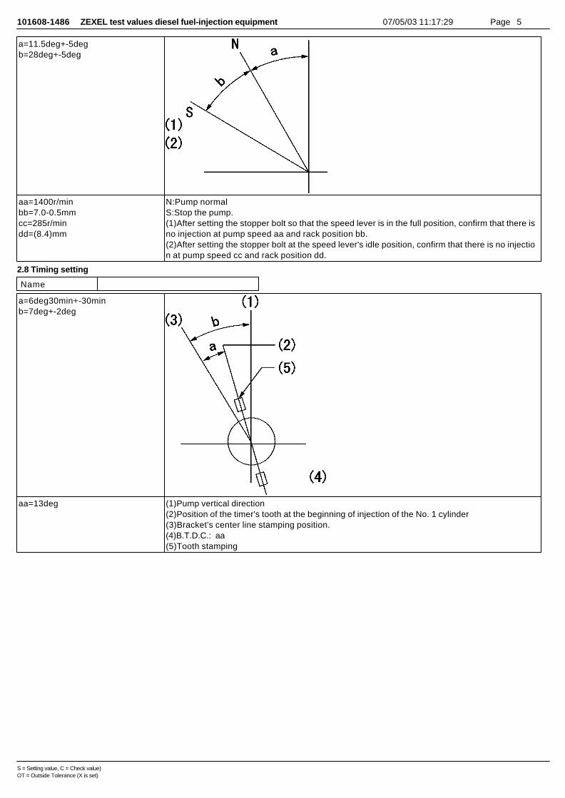
101608-1486 ZEXEL test values diesel fuel-injection equipment 07/05/03 11:17:29 Page 5
a=11.5deg+-5degb=28deg+-5deg
aa=1400r/minbb=7.0-0.5mmcc=285r/mindd=(8.4)mm
N:Pump normalS:Stop the pump.(1)After setting the stopper bolt so that the speed lever is in the full position, confirm that there isno injection at pump speed aa and rack position bb.(2)After setting the stopper bolt at the speed lever's idle position, confirm that there is no injection at pump speed cc and rack position dd.
2.8 Timing setting
Name
a=6deg30min+-30minb=7deg+-2deg
aa=13deg (1)Pump vertical direction(2)Position of the timer's tooth at the beginning of injection of the No. 1 cylinder(3)Bracket's center line stamping position.(4)B.T.D.C.: aa(5)Tooth stamping
S = Setting value, C = Check value)OT = Outside Tolerance (X is set)
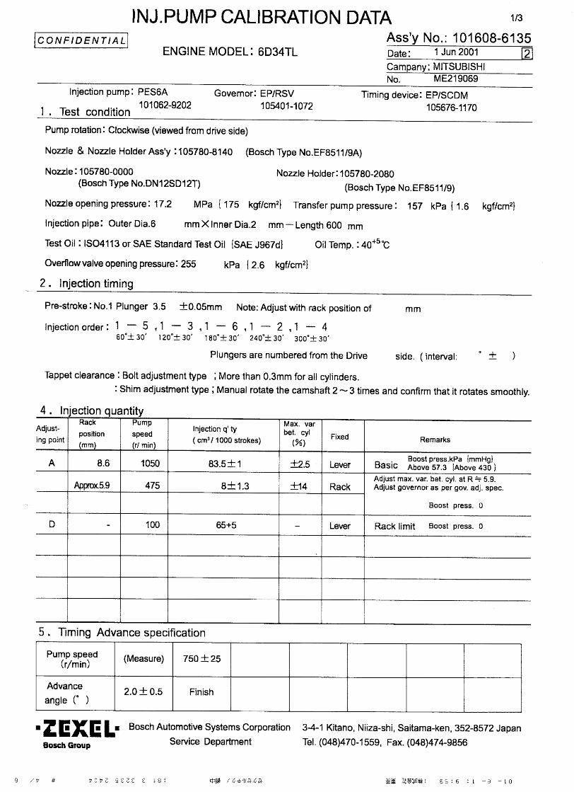
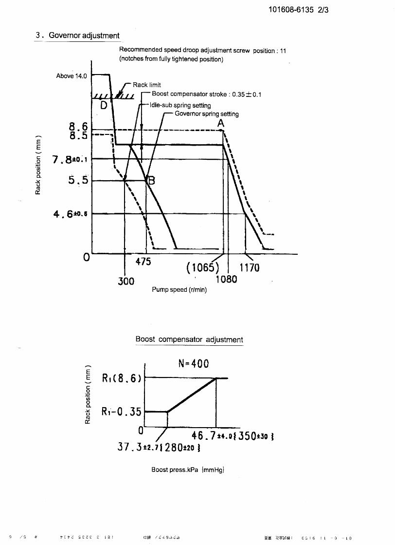
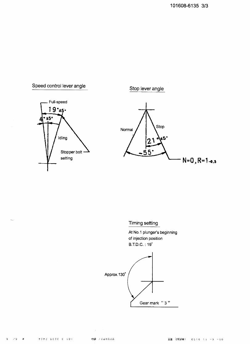
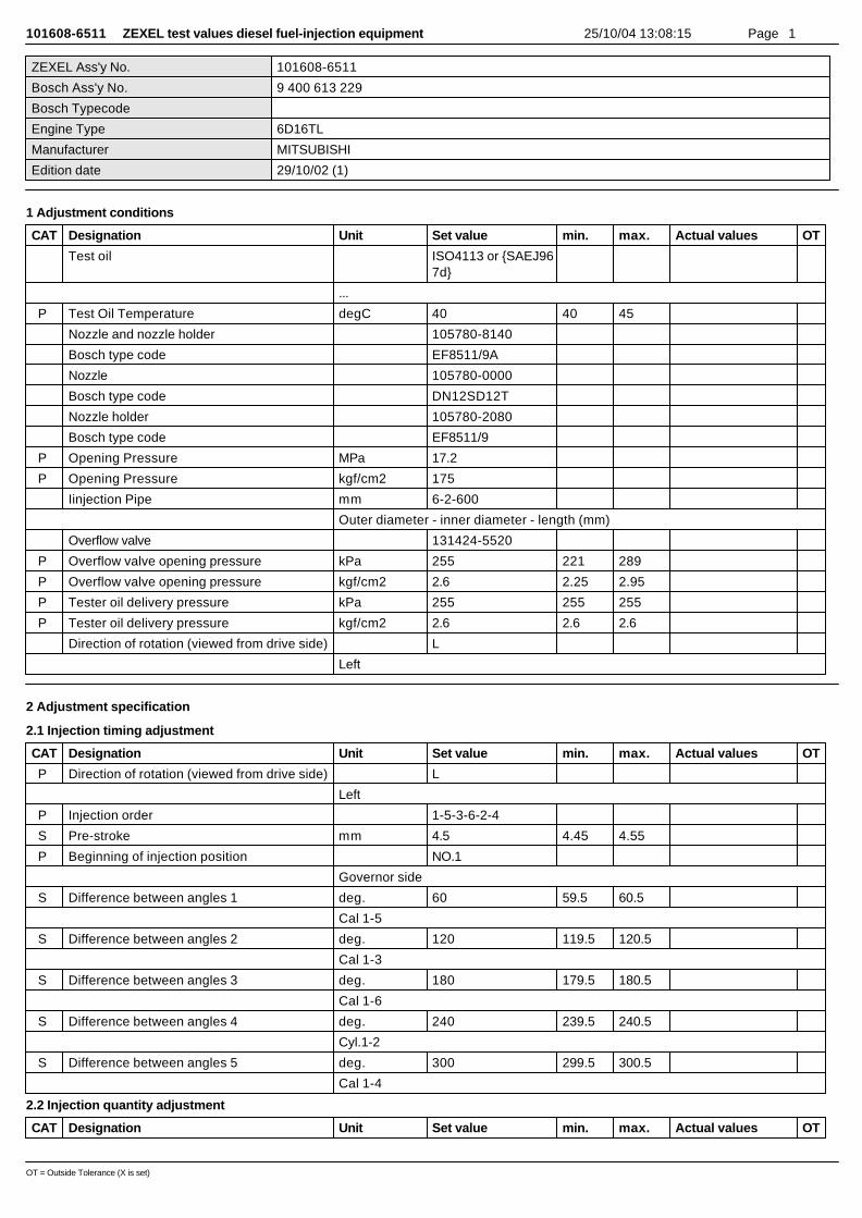
101608-6511 ZEXEL test values diesel fuel-injection equipment 25/10/04 13:08:15 Page 1
ZEXEL Ass'y No. 101608-6511
Bosch Ass'y No. 9 400 613 229
Bosch Typecode
Engine Type 6D16TL
Manufacturer MITSUBISHI
Edition date 29/10/02 (1)
1 Adjustment conditions
CAT Designation Unit Set value min. max. Actual values OT
Test oil ISO4113 or {SAEJ967d}
...
P Test Oil Temperature degC 40 40 45
Nozzle and nozzle holder 105780-8140
Bosch type code EF8511/9A
Nozzle 105780-0000
Bosch type code DN12SD12T
Nozzle holder 105780-2080
Bosch type code EF8511/9
P Opening Pressure MPa 17.2
P Opening Pressure kgf/cm2 175
Iinjection Pipe mm 6-2-600
Outer diameter - inner diameter - length (mm)
Overflow valve 131424-5520
P Overflow valve opening pressure kPa 255 221 289
P Overflow valve opening pressure kgf/cm2 2.6 2.25 2.95
P Tester oil delivery pressure kPa 255 255 255
P Tester oil delivery pressure kgf/cm2 2.6 2.6 2.6
Direction of rotation (viewed from drive side) L
Left
2 Adjustment specification
2.1 Injection timing adjustment
CAT Designation Unit Set value min. max. Actual values OT
P Direction of rotation (viewed from drive side) L
Left
P Injection order 1-5-3-6-2-4
S Pre-stroke mm 4.5 4.45 4.55
P Beginning of injection position NO.1
Governor side
S Difference between angles 1 deg. 60 59.5 60.5
Cal 1-5
S Difference between angles 2 deg. 120 119.5 120.5
Cal 1-3
S Difference between angles 3 deg. 180 179.5 180.5
Cal 1-6
S Difference between angles 4 deg. 240 239.5 240.5
Cyl.1-2
S Difference between angles 5 deg. 300 299.5 300.5
Cal 1-4
2.2 Injection quantity adjustment
CAT Designation Unit Set value min. max. Actual values OT
OT = Outside Tolerance (X is set)
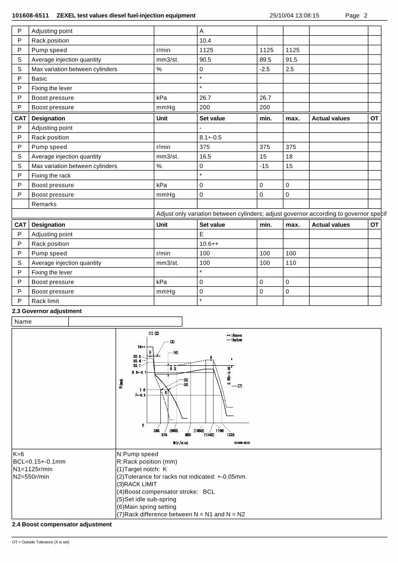
101608-6511 ZEXEL test values diesel fuel-injection equipment 25/10/04 13:08:15 Page 2
P Adjusting point A
P Rack position 10.4
P Pump speed r/min 1125 1125 1125
S Average injection quantity mm3/st. 90.5 89.5 91.5
S Max variation between cylinders % 0 -2.5 2.5
P Basic *
P Fixing the lever *
P Boost pressure kPa 26.7 26.7
P Boost pressure mmHg 200 200
CAT Designation Unit Set value min. max. Actual values OT
P Adjusting point -
P Rack position 8.1+-0.5
P Pump speed r/min 375 375 375
S Average injection quantity mm3/st. 16.5 15 18
S Max variation between cylinders % 0 -15 15
P Fixing the rack *
P Boost pressure kPa 0 0 0
P Boost pressure mmHg 0 0 0
Remarks
Adjust only variation between cylinders; adjust governor according to governor specifications.
CAT Designation Unit Set value min. max. Actual values OT
P Adjusting point E
P Rack position 10.6++
P Pump speed r/min 100 100 100
S Average injection quantity mm3/st. 100 100 110
P Fixing the lever *
P Boost pressure kPa 0 0 0
P Boost pressure mmHg 0 0 0
P Rack limit *
2.3 Governor adjustment
Name
K=6BCL=0.15+-0.1mmN1=1125r/minN2=550r/min
N:Pump speedR:Rack position (mm)(1)Target notch: K(2)Tolerance for racks not indicated: +-0.05mm.(3)RACK LIMIT(4)Boost compensator stroke: BCL(5)Set idle sub-spring(6)Main spring setting(7)Rack difference between N = N1 and N = N2
2.4 Boost compensator adjustment
OT = Outside Tolerance (X is set)

101608-6511 ZEXEL test values diesel fuel-injection equipment 25/10/04 13:08:15 Page 3
CAT Designation Unit Set value min. max. Actual values OT
P Pump speed r/min 500 500 500
P Rack position R1-0.15
S Boost pressure kPa 11.3 11.3 11.3
About
S Boost pressure mmHg 85 85 85
About
CAT Designation Unit Set value min. max. Actual values OT
P Pump speed r/min 500 500 500
P Rack position R1-0.1
S Boost pressure kPa 12 9.3 14.7
S Boost pressure mmHg 90 70 110
CAT Designation Unit Set value min. max. Actual values OT
P Pump speed r/min 500 500 500
P Rack position R1(9.75)
S Boost pressure kPa 13.3 13.3 13.3
About
S Boost pressure mmHg 100 100 100
About
2.5 Timer adjustment
CAT Designation Unit Set value min. max. Actual values OT
P Pump speed r/min 0
S Advance angle deg. 3 2.5 3.5
Load 0/4
CAT Designation Unit Set value min. max. Actual values OT
P Pump speed r/min 550+50
S Advance angle deg. 3 2.5 3.5
Load 0/4
Remarks
Start
CAT Designation Unit Set value min. max. Actual values OT
P Pump speed r/min 650-50
S Advance angle deg. 0 0 0
Load 0/4
Remarks
Finish
2.6 Speed control lever angle
Name
a=20deg+-5degb=1deg+-5deg
OT = Outside Tolerance (X is set)
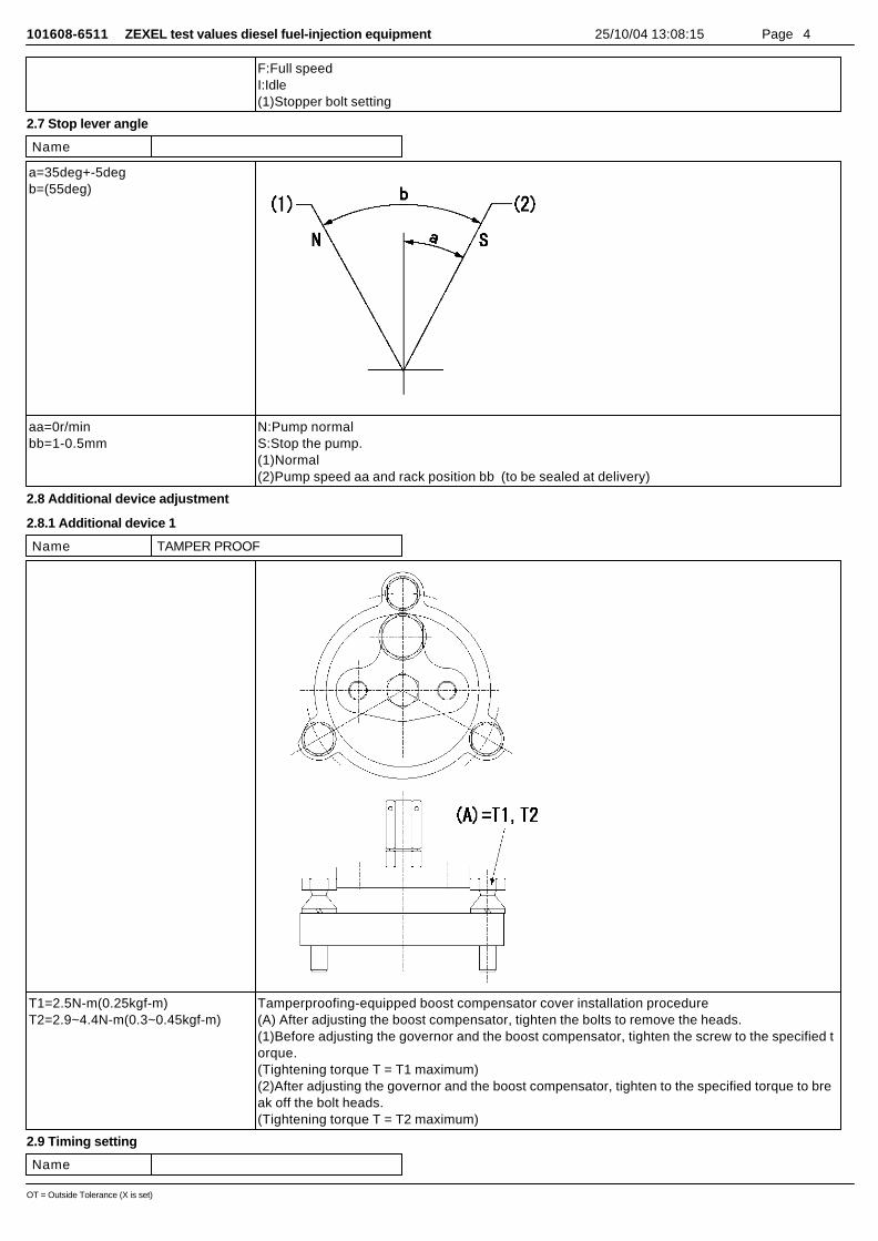
101608-6511 ZEXEL test values diesel fuel-injection equipment 25/10/04 13:08:15 Page 4
F:Full speedI:Idle(1)Stopper bolt setting
2.7 Stop lever angle
Name
a=35deg+-5degb=(55deg)
aa=0r/minbb=1-0.5mm
N:Pump normalS:Stop the pump.(1)Normal(2)Pump speed aa and rack position bb (to be sealed at delivery)
2.8 Additional device adjustment
2.8.1 Additional device 1
Name TAMPER PROOF
T1=2.5N-m(0.25kgf-m)T2=2.9~4.4N-m(0.3~0.45kgf-m)
Tamperproofing-equipped boost compensator cover installation procedure(A) After adjusting the boost compensator, tighten the bolts to remove the heads.(1)Before adjusting the governor and the boost compensator, tighten the screw to the specified torque.(Tightening torque T = T1 maximum)(2)After adjusting the governor and the boost compensator, tighten to the specified torque to break off the bolt heads.(Tightening torque T = T2 maximum)
2.9 Timing setting
Name
OT = Outside Tolerance (X is set)
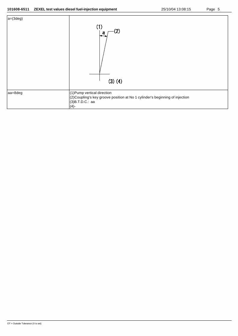
101608-6511 ZEXEL test values diesel fuel-injection equipment 25/10/04 13:08:15 Page 5
a=(3deg)
aa=8deg (1)Pump vertical direction(2)Coupling's key groove position at No 1 cylinder's beginning of injection(3)B.T.D.C.: aa(4)-
OT = Outside Tolerance (X is set)
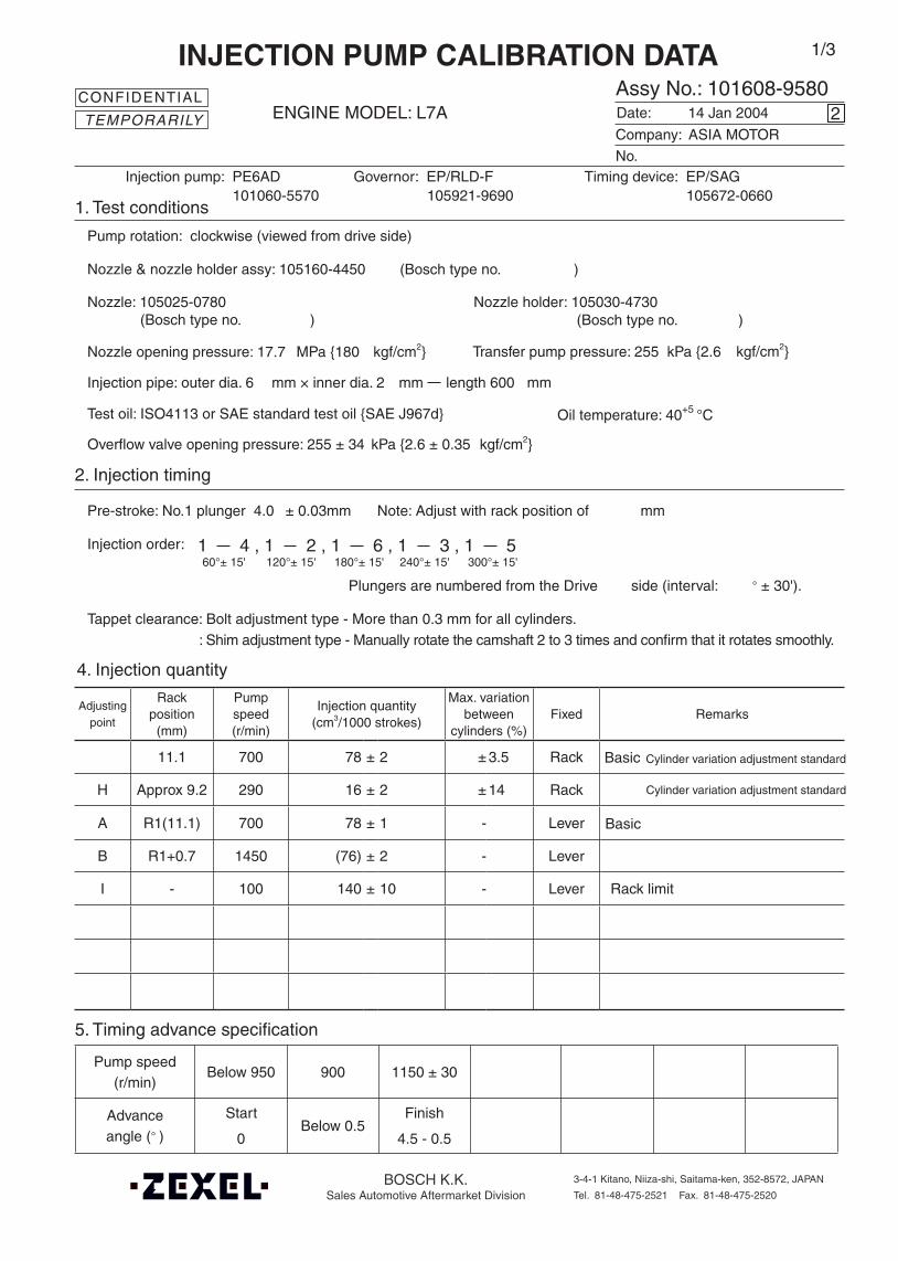
Oil temperature: 40+5 °C
BOSCH K.K.Sales Automotive Aftermarket Division
3-4-1 Kitano, Niiza-shi, Saitama-ken, 352-8572, JAPAN
Tel. 81-48-475-2521 Fax. 81-48-475-2520
Adjustingpoint
Rackposition
(mm)
Pumpspeed(r/min)
Injection quantity(cm3/1000 strokes)
Max. variationbetween
cylinders (%)Fixed Remarks
11.1 700 78 ± 2 ± 3.5 Rack
H Approx 9.2 290 16 ± 2 ± 14 Rack
A R1(11.1) 700 78 ± 1 - Lever
B R1+0.7 1450 (76) ± 2 - Lever
I - 100 140 ± 10 - Lever Rack limit
Injection order:
Pump speed(r/min)
Below 950 900 1150 ± 30
Advanceangle (° )
Start
0 Below 0.5
Finish
4.5 - 0.5
4. Injection quantity
5. Timing advance specification
Company:
Assy No.: 101608-9580ENGINE MODEL: L7A
No. Governor: EP/RLD-F Timing device: EP/SAG
1. Test conditions
Date:
Pump rotation: clockwise (viewed from drive side)
Injection pump: PE6AD105921-9690 105672-0660
kgf/cm2}
2. Injection timing
Pre-stroke: No.1 plunger 4.0 ± 0.03mm mm
Plungers are numbered from the Drive ° ± 30').
Tappet clearance: Bolt adjustment type - More than 0.3 mm for all cylinders.: Shim adjustment type - Manually rotate the camshaft 2 to 3 times and confirm that it rotates smoothly.
CONFIDENTIAL
INJECTION PUMP CALIBRATION DATA
14 Jan 2004
ASIA MOTOR
101060-5570
Injection pipe: outer dia. 6 mm × inner dia. 2 mm length 600 mm
Nozzle opening pressure: 17.7 MPa {180 kgf/cm2}
Nozzle: 105025-0780 Nozzle holder: 105030-4730(Bosch type no. ) (Bosch type no. )
Nozzle & nozzle holder assy: 105160-4450 (Bosch type no. )
Test oil: ISO4113 or SAE standard test oil {SAE J967d}
side (interval:
2
Transfer pump pressure: 255 kPa {2.6
Note: Adjust with rack position of
1 4 , 1 2 , 1 6 , 1 3 , 1 560°± 15' 120°± 15' 180°± 15' 240°± 15' 300°± 15'
1/3
Overflow valve opening pressure: 255 ± 34 kPa {2.6 ± 0.35 kgf/cm2}
Cylinder variation adjustment standardBasic
TEMPORARILY
Cylinder variation adjustment standard
Basic

101608-9580 2/3
3. Governor adjustment
0190300 325
850
Rac
k po
sitio
n (m
m)
Pump speed (r/min)
11.5
11.0+0.35-0.30
R1+0.55
0Below 225 (1400)
A
B
Rac
k po
sitio
n (m
m)
Pump speed (r/min)
Torque cam no. ‘M76’
R1+0.7
R1(11.1)
(900)
(1100)
1550±10
400
5.5±0.3
9.0Approx 9.2
Full load adjustment
Idling adjustment
I
7.8±0.07
290
Microswitch adjustment Adjust the bolt so that the microswitch operates at a control lever position ofR= 8.6 ± 0.1 mm and a pump speed of 415r/min.
Rack limit
R1+0.15
R1-0.65
8.35
700
(800)
(1300)
1660±50
HJ
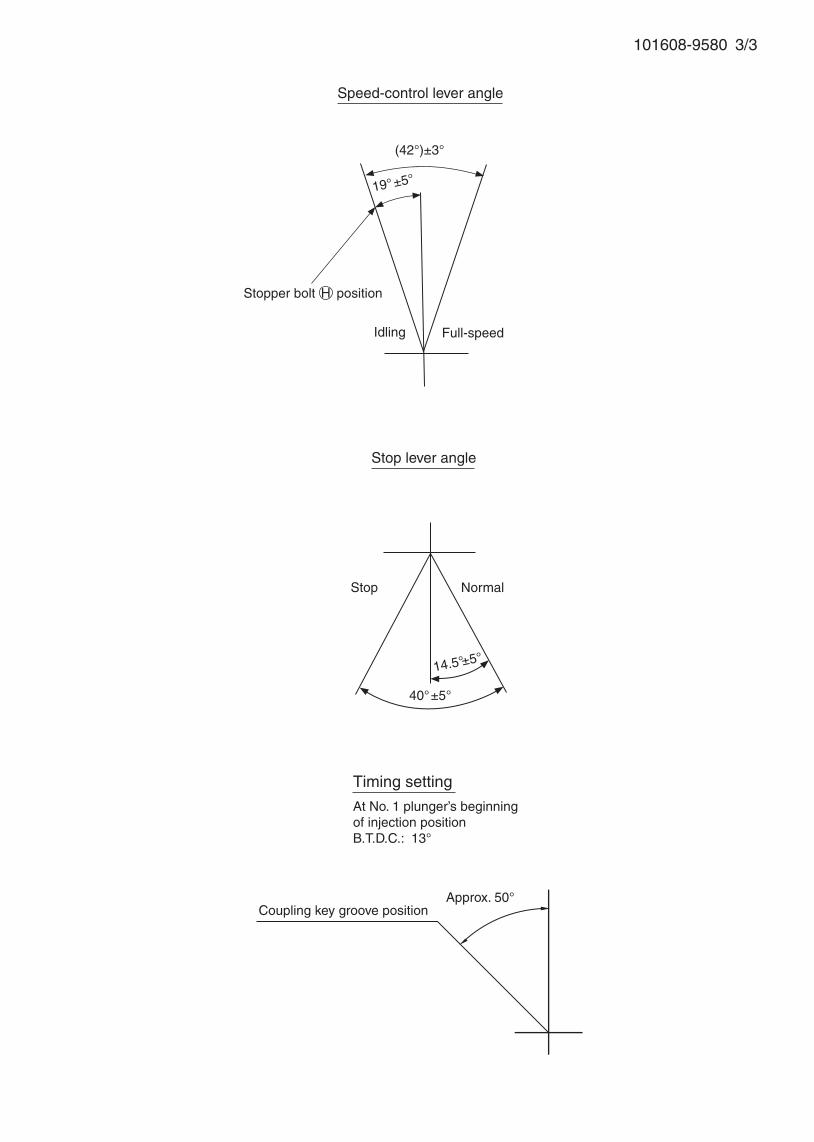
101608-9580 3/3
Speed-control lever angle
Idling Full-speed
Coupling key groove position
Stopper bolt H position
Timing setting
At No. 1 plunger’s beginning of injection positionB.T.D.C.: 13°
Approx. 50°
14.5°±5°
Stop lever angle
40°±5°
19°±5°
(42°)±3°
Stop Normal
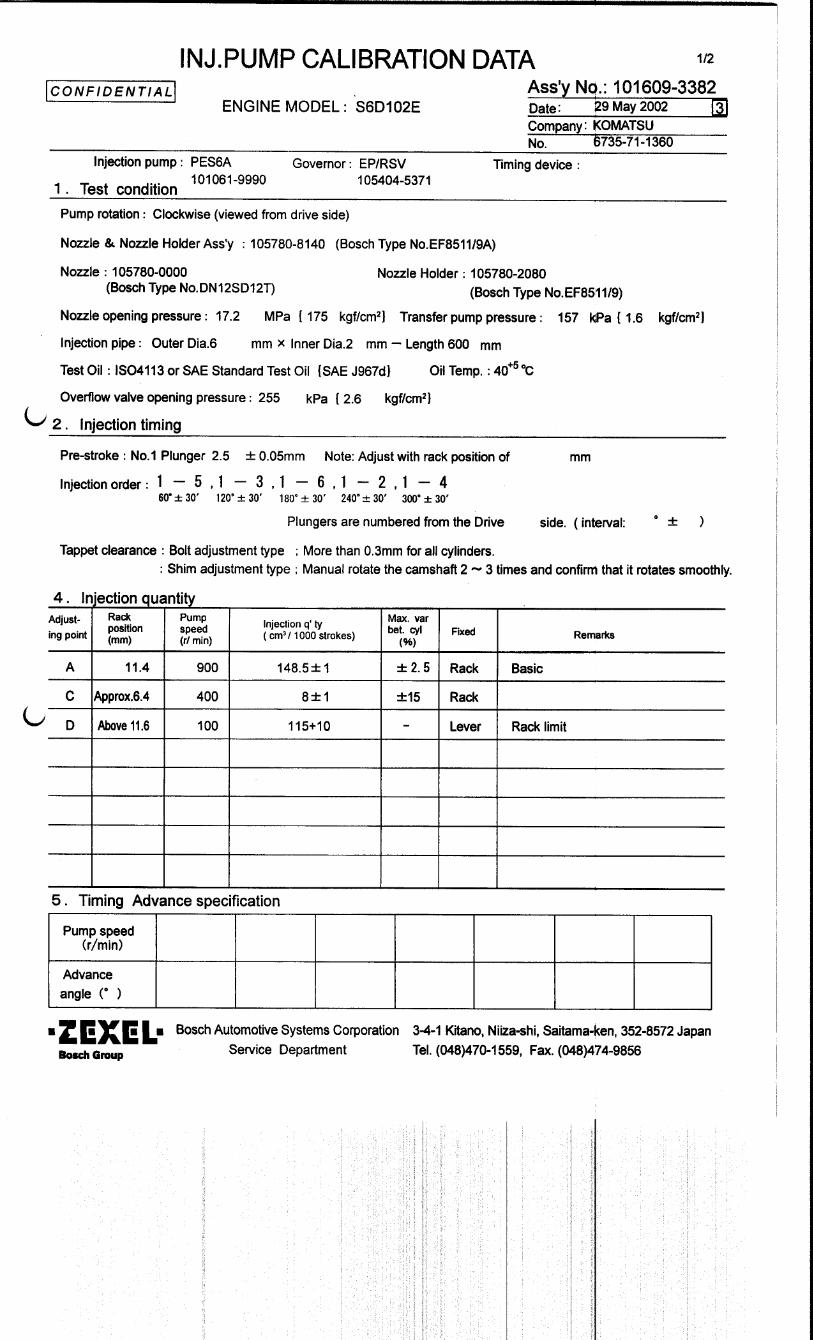
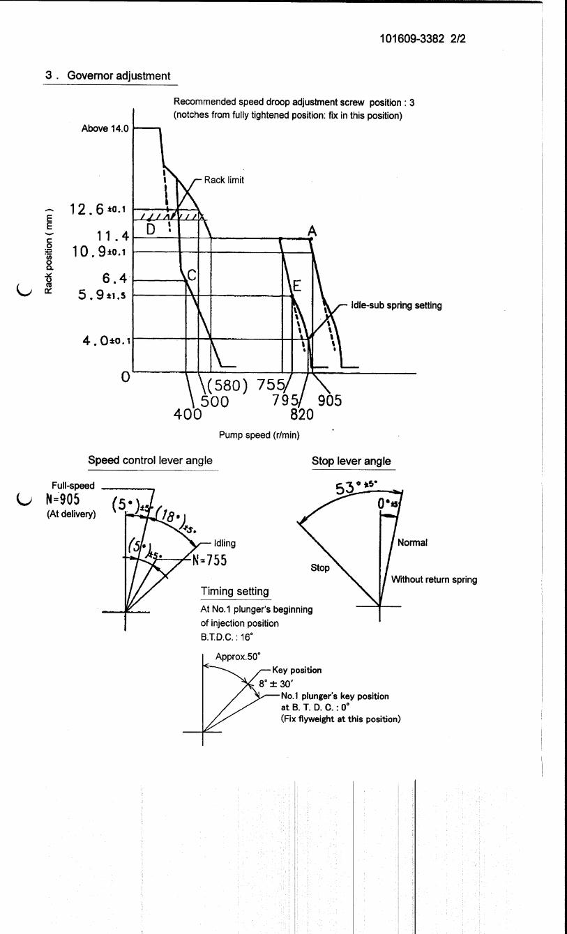

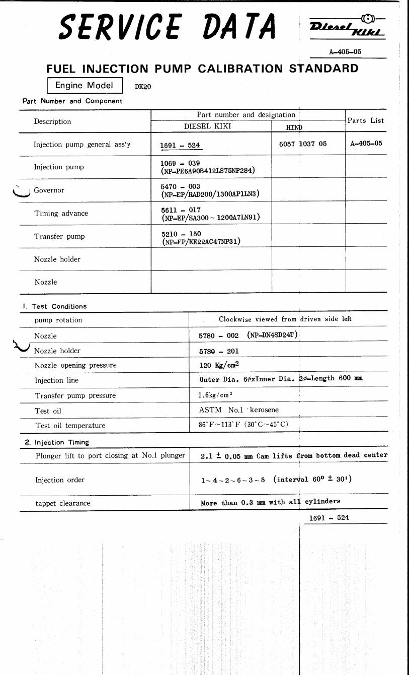
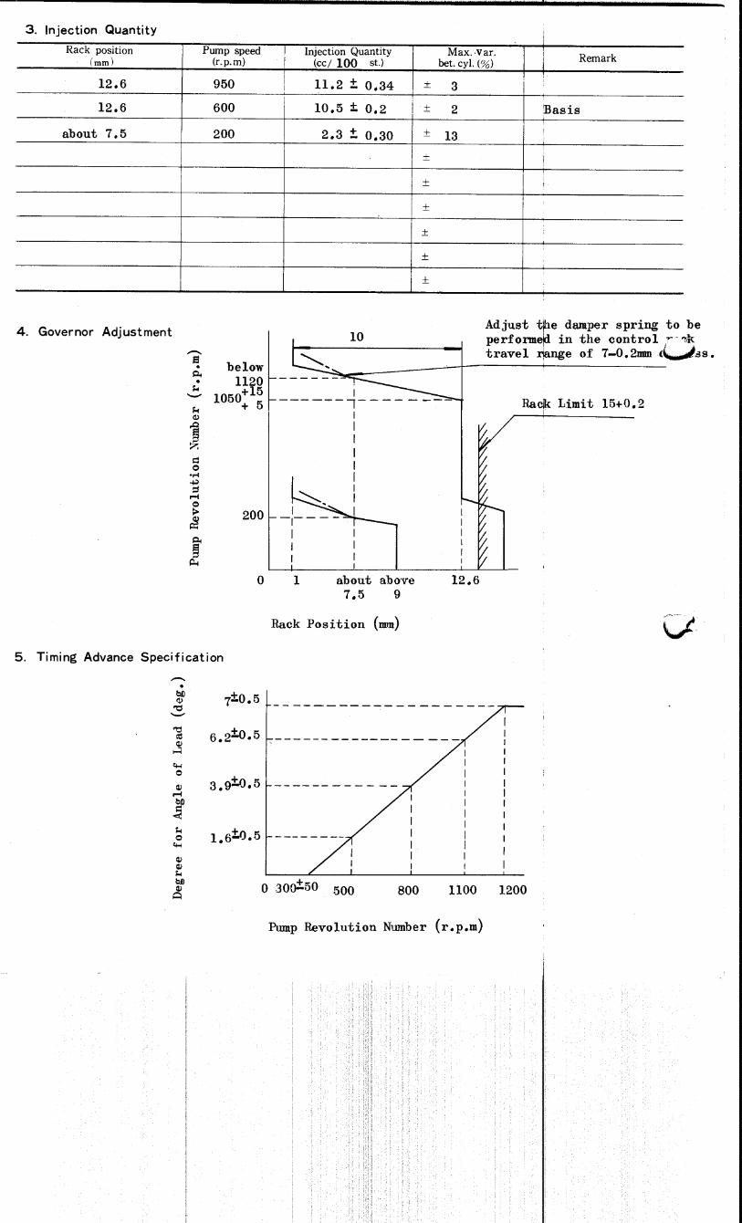
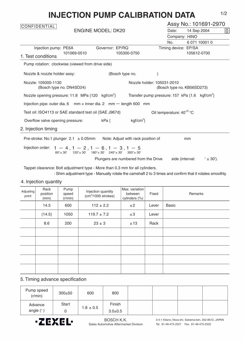
Oil temperature: 40+5 °C
BOSCH K.K.Sales Automotive Aftermarket Division
3-4-1 Kitano, Niiza-shi, Saitama-ken, 352-8572, JAPAN
Tel. 81-48-475-2521 Fax. 81-48-475-2520
Adjustingpoint
Rackposition
(mm)
Pumpspeed(r/min)
Injection quantity(cm3/1000 strokes)
Max. variationbetween
cylinders (%)Fixed Remarks
14.5 600 112 ± 2.2 ± 2 Lever Basic
(14.5) 1050 119.7 ± 7.2 ± 3 Lever
8.6 200 23 ± 3 ± 13 Rack
Injection order:
4. Injection quantity
5. Timing advance specification
Company:
Assy No.: 101691-2970ENGINE MODEL: DK20
No. Governor: EP/RQ Timing device: EP/SA
1. Test conditions
Date:
Pump rotation: clockwise (viewed from drive side)
Injection pump: PE6A105300-0750 105612-0700
kgf/cm2}
2. Injection timing
Pre-stroke: No.1 plunger 2.1 ± 0.05mm mm
Plungers are numbered from the Drive ° ± 30').
Tappet clearance: Bolt adjustment type - More than 0.3 mm for all cylinders.: Shim adjustment type - Manually rotate the camshaft 2 to 3 times and confirm that it rotates smoothly.
CONFIDENTIAL
INJECTION PUMP CALIBRATION DATA
14 Sep 2004
6 071 10001 0
101069-0510
Injection pipe: outer dia. 6 mm × inner dia. 2 mm length 600 mm
Nozzle opening pressure: 11.8 MPa {120 kgf/cm2}
Test oil: ISO4113 or SAE standard test oil {SAE J967d}
side (interval:
0
Transfer pump pressure: 157 kPa {1.6
Note: Adjust with rack position of
1/2
1 4 , 1 2 , 1 6 , 1 3 , 1 560°± 30' 120°± 30' 180°± 30' 240°± 30' 300°± 30'
Overflow valve opening pressure: kPa { kgf/cm2}
HINO
Nozzle: 105000-1130 Nozzle holder: 105031-2010(Bosch type no. DN4SD24) (Bosch type no. KB56SD273)
Nozzle & nozzle holder assy: (Bosch type no. )
Pump speed(r/min)
300±50 600 800
Advanceangle (° )
Start
0 1.8 ± 0.5
Finish
3.0±0.5
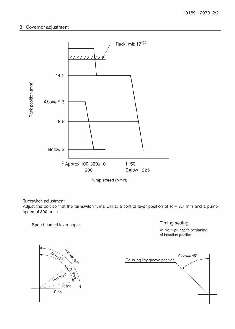
101691-2970 2/2
3. Governor adjustment
0 Approx 100
Rac
k po
sitio
n (m
m)
Pump speed (r/min)
Above 9.6
1150
Rack limit: 17+0.2 0
8.6
14.5
Below 3
200320±10
Below 1225
Speed-control lever angle
26.5°±3°
Full-load
Stop
Idling
54.5°±5° Coupling key groove position
Timing setting
At No. 1 plunger’s beginning of injection position
Approx. 40°
Turnswitch adjustmentAdjust the bolt so that the turnswitch turns ON at a control lever position of R = 8.7 mm and a pump speed of 300 r/min.
Approx. 90°
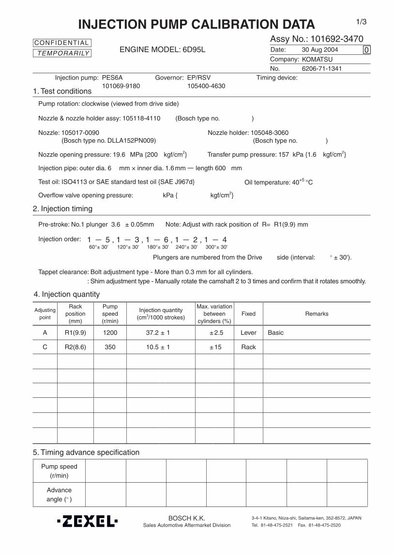
Oil temperature: 40+5 °C
BOSCH K.K.Sales Automotive Aftermarket Division
3-4-1 Kitano, Niiza-shi, Saitama-ken, 352-8572, JAPAN
Tel. 81-48-475-2521 Fax. 81-48-475-2520
Adjustingpoint
Rackposition
(mm)
Pumpspeed(r/min)
Injection quantity(cm3/1000 strokes)
Max. variationbetween
cylinders (%)Fixed Remarks
A R1(9.9) 1200 37.2 ± 1 ± 2.5 Lever Basic
C R2(8.6) 350 10.5 ± 1 ± 15 Rack
Injection order:
Pump speed(r/min)
Advanceangle (° )
4. Injection quantity
5. Timing advance specification
Company:
Assy No.: 101692-3470ENGINE MODEL: 6D95L
No. Governor: EP/RSV Timing device:
1. Test conditions
Date:
Pump rotation: clockwise (viewed from drive side)
Injection pump: PES6A105400-4630
kgf/cm2}
2. Injection timing
Pre-stroke: No.1 plunger 3.6 ± 0.05mm mm
Plungers are numbered from the Drive ° ± 30').
Tappet clearance: Bolt adjustment type - More than 0.3 mm for all cylinders.: Shim adjustment type - Manually rotate the camshaft 2 to 3 times and confirm that it rotates smoothly.
CONFIDENTIAL
INJECTION PUMP CALIBRATION DATA
30 Aug 2004
6206-71-1341
101069-9180
Injection pipe: outer dia. 6 mm × inner dia. 1.6mm length 600 mm
Nozzle opening pressure: 19.6 MPa {200 kgf/cm2}
Nozzle: 105017-0090 Nozzle holder: 105048-3060(Bosch type no. DLLA152PN009) (Bosch type no. )
Nozzle & nozzle holder assy: 105118-4110 (Bosch type no. )
Test oil: ISO4113 or SAE standard test oil {SAE J967d}
side (interval:
0
Transfer pump pressure: 157 kPa {1.6
Note: Adjust with rack position of R= R1(9.9)
1 5 , 1 3 , 1 6 , 1 2 , 1 460°± 30' 120°± 30' 180°± 30' 240°± 30' 300°± 30'
KOMATSU
1/3
Overflow valve opening pressure: kPa { kgf/cm2}
TEMPORARILY
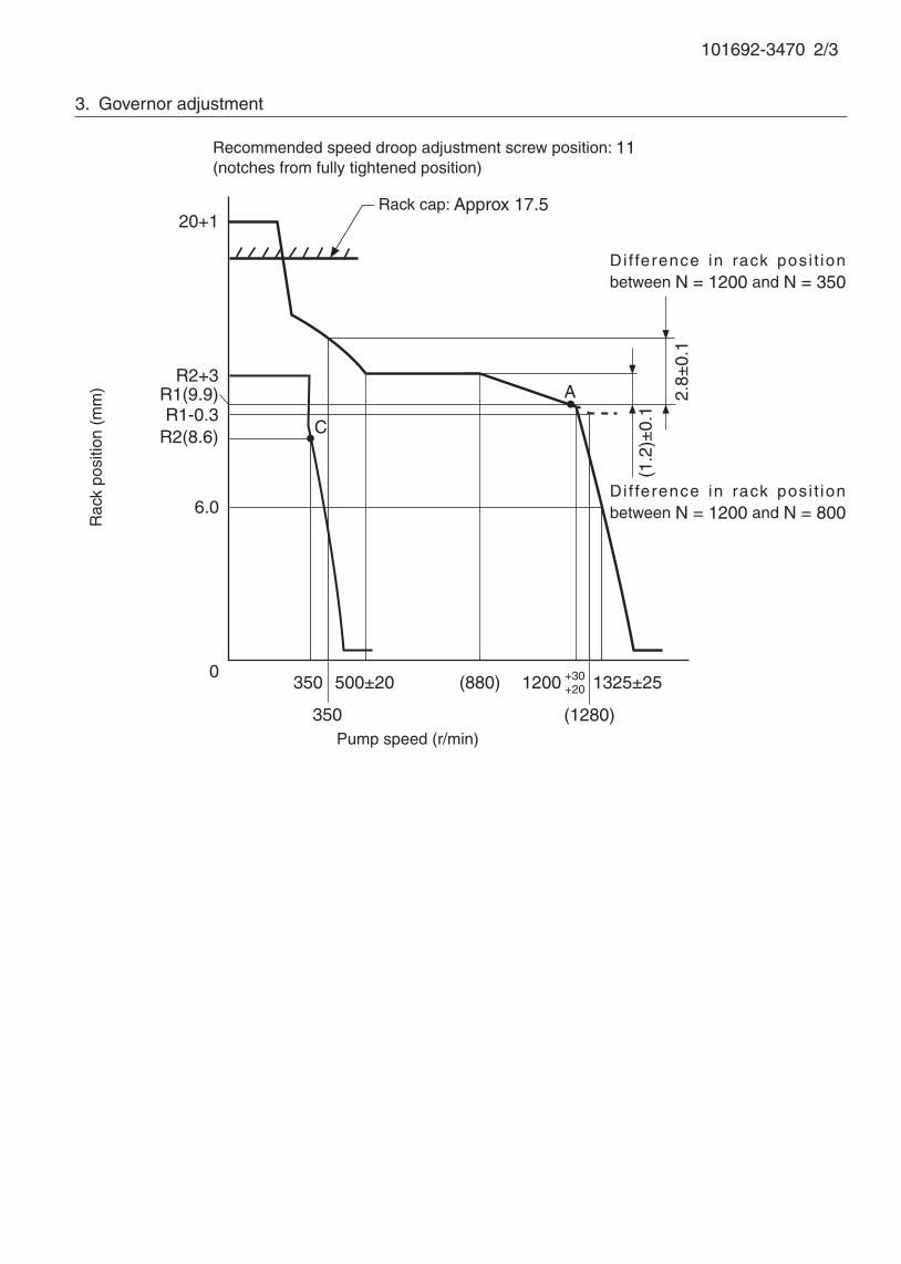
101692-3470 2/3
Recommended speed droop adjustment screw position: 11(notches from fully tightened position)
3. Governor adjustment
Pump speed (r/min)
0500±20 (880)
A
R2(8.6)
Rac
k po
sitio
n (m
m)
6.0
Rack cap: Approx 17.5
R2+3
(1280)
1200 1325±25350
C
20+1
R1(9.9)
350
+30+20
R1-0.3
Di f ference in rack posi t ion between N = 1200 and N = 800
Di f ference in rack posi t ion between N = 1200 and N = 350
(1.2
)±0.
1
2.8±
0.1
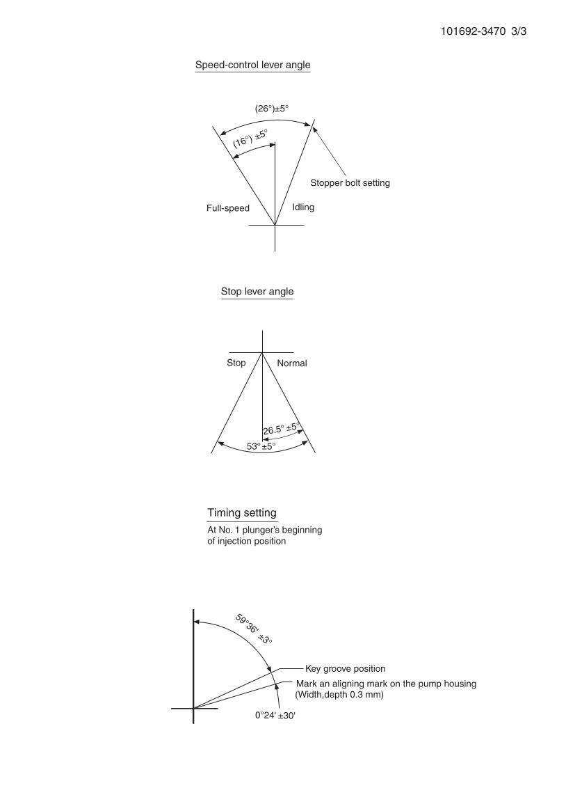
101692-3470 3/3
Stopper bolt setting
Speed-control lever angle
Idling
Stop lever angle
Stop
Full-speed
Normal
(16°) ±5°
(26°)±5°
53°±5° 26.5° ±5°
59°36' ±3°
Timing setting
At No. 1 plunger’s beginning of injection position
Key groove position
0°24' ±30'
Mark an aligning mark on the pump housing(Width,depth 0.3 mm)
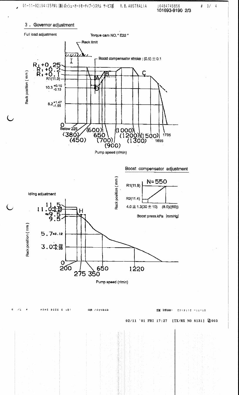
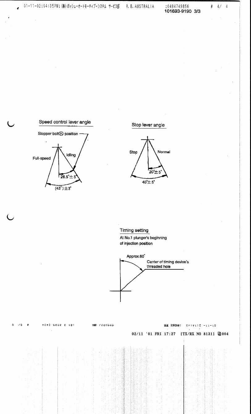
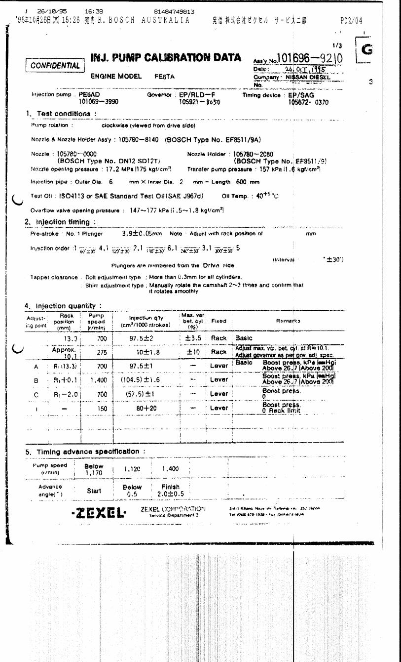
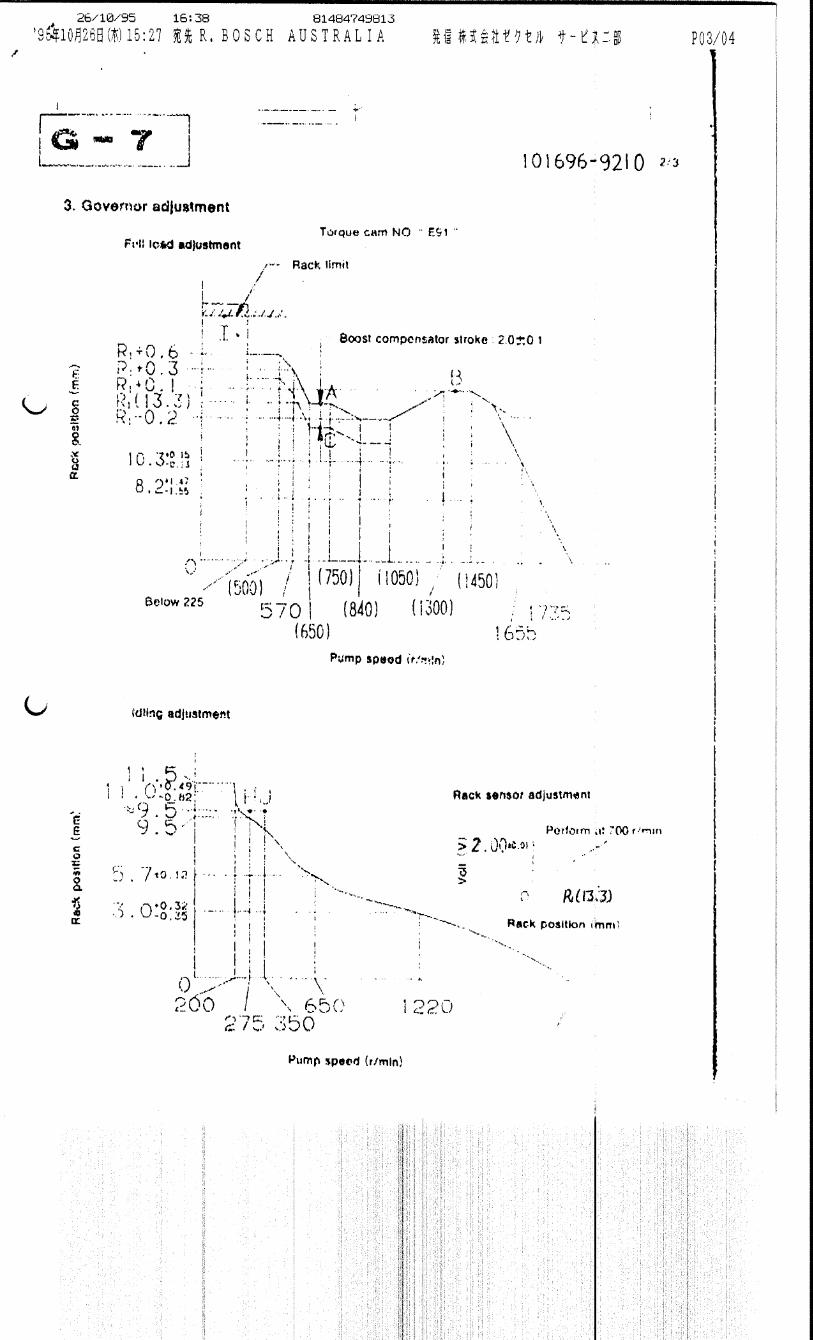
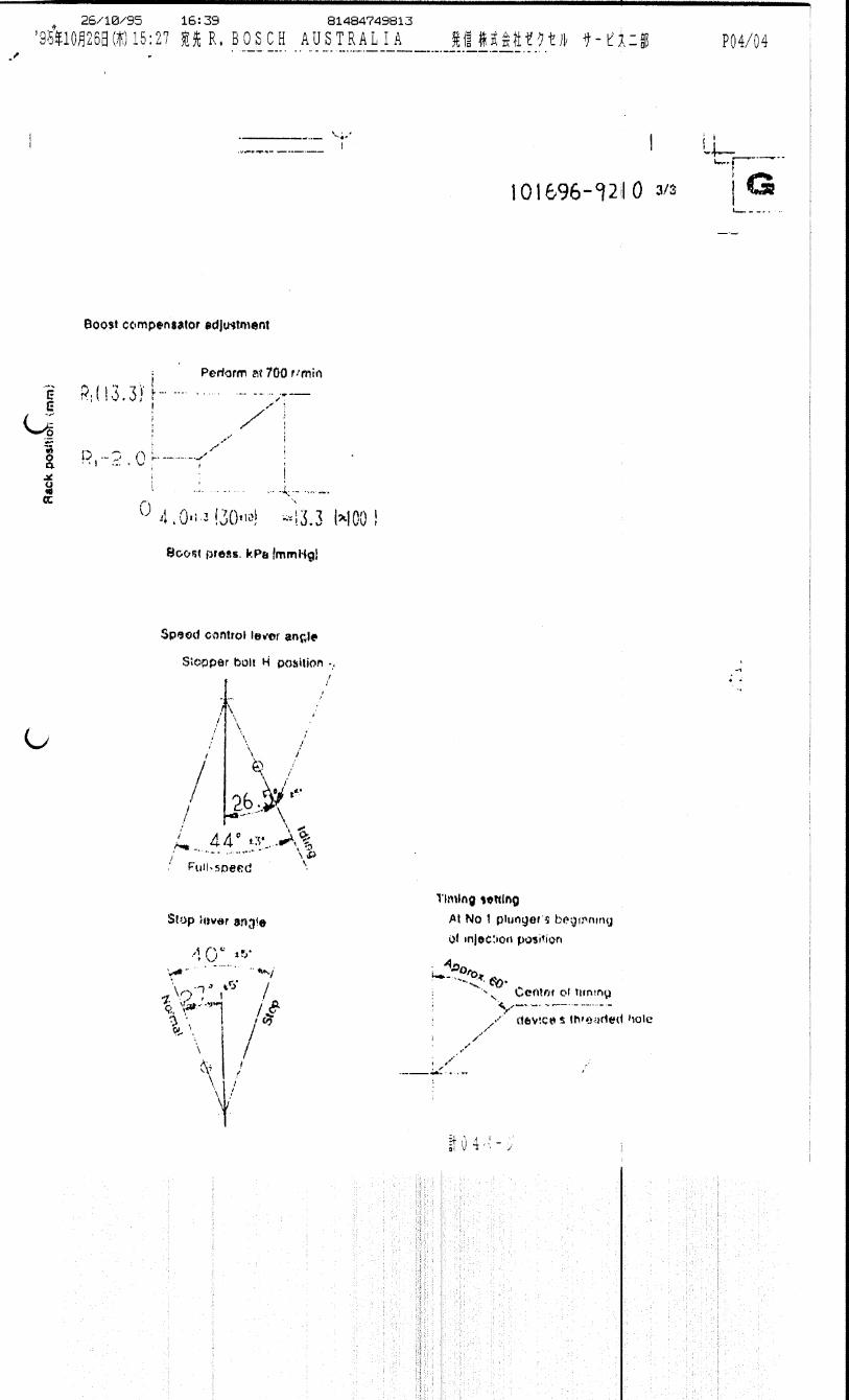
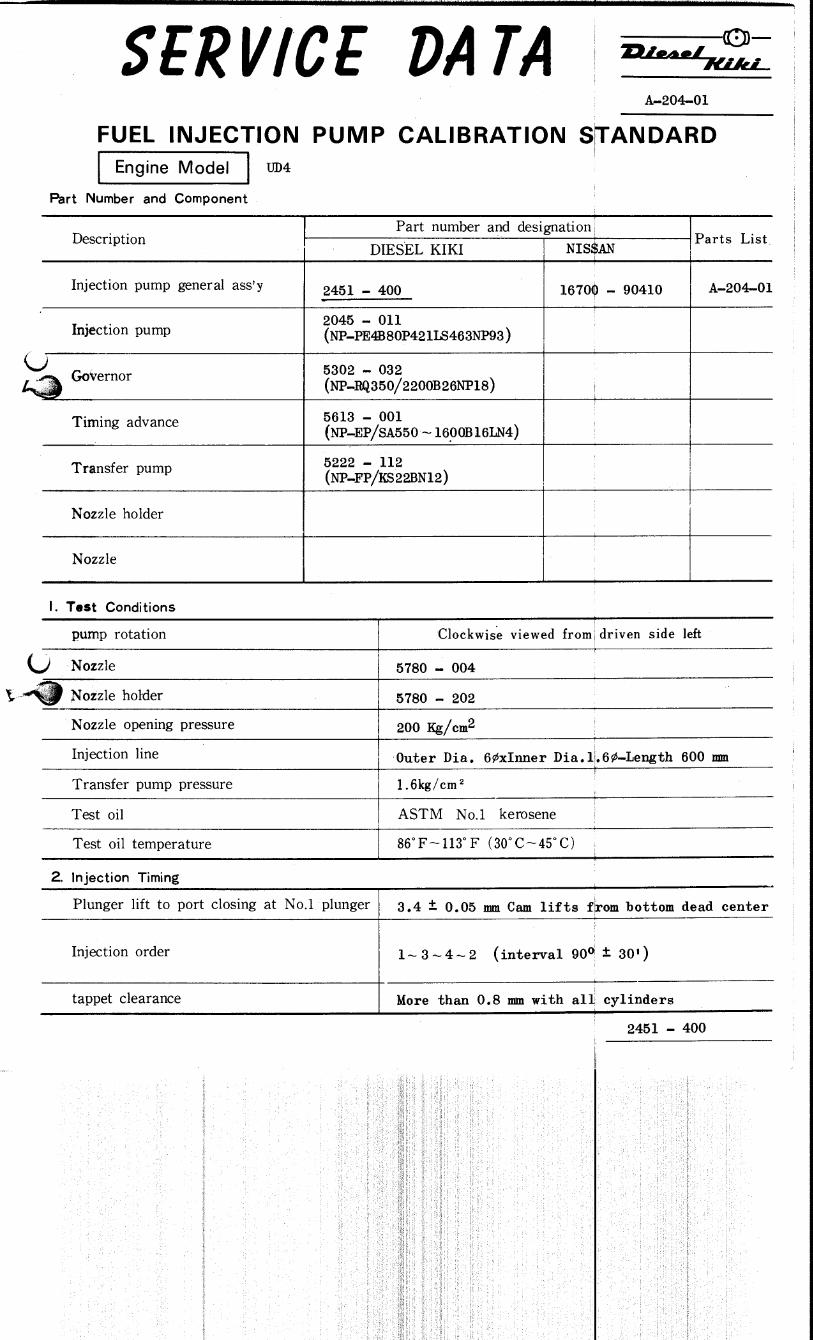
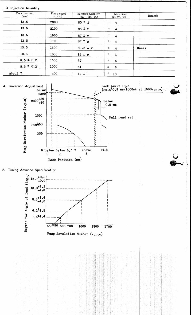
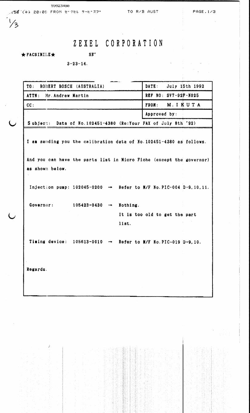

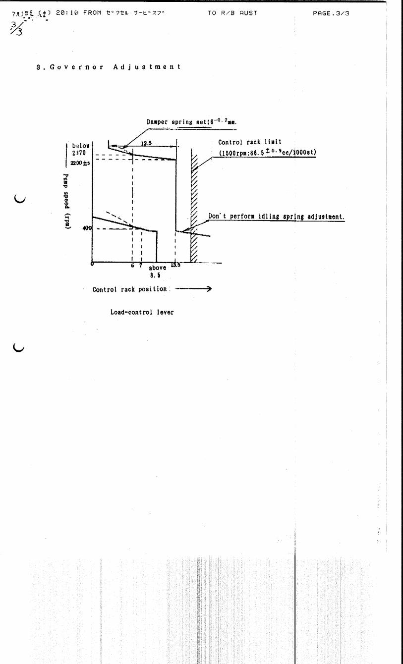
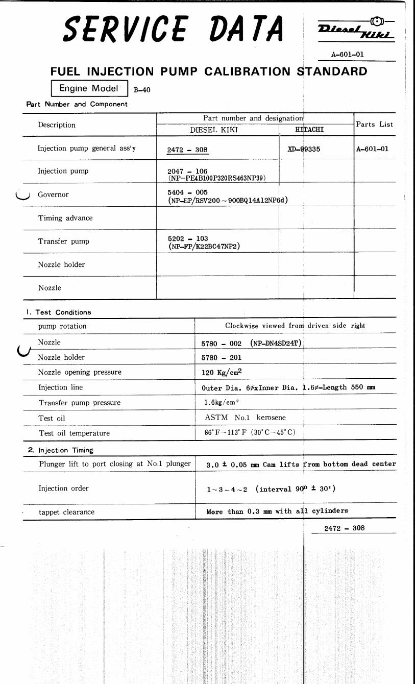
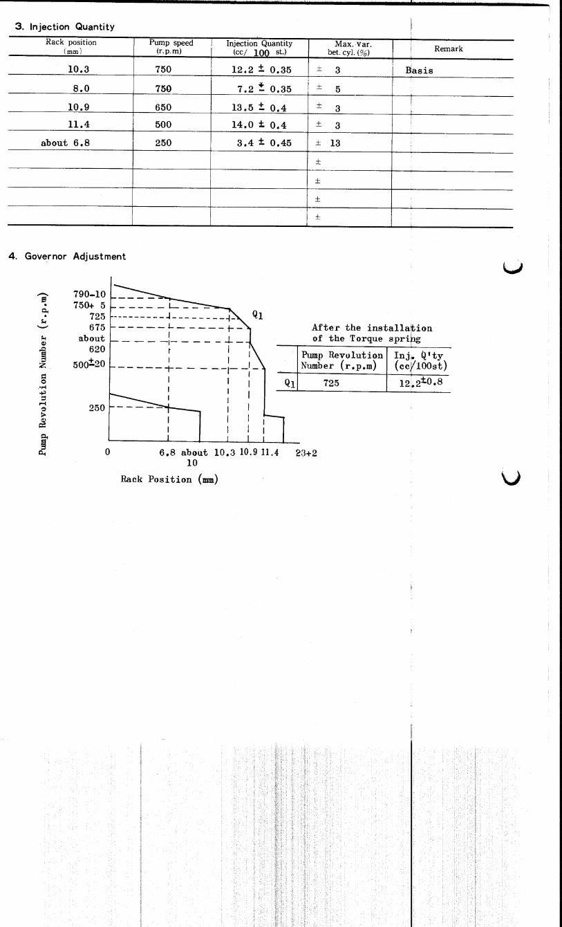
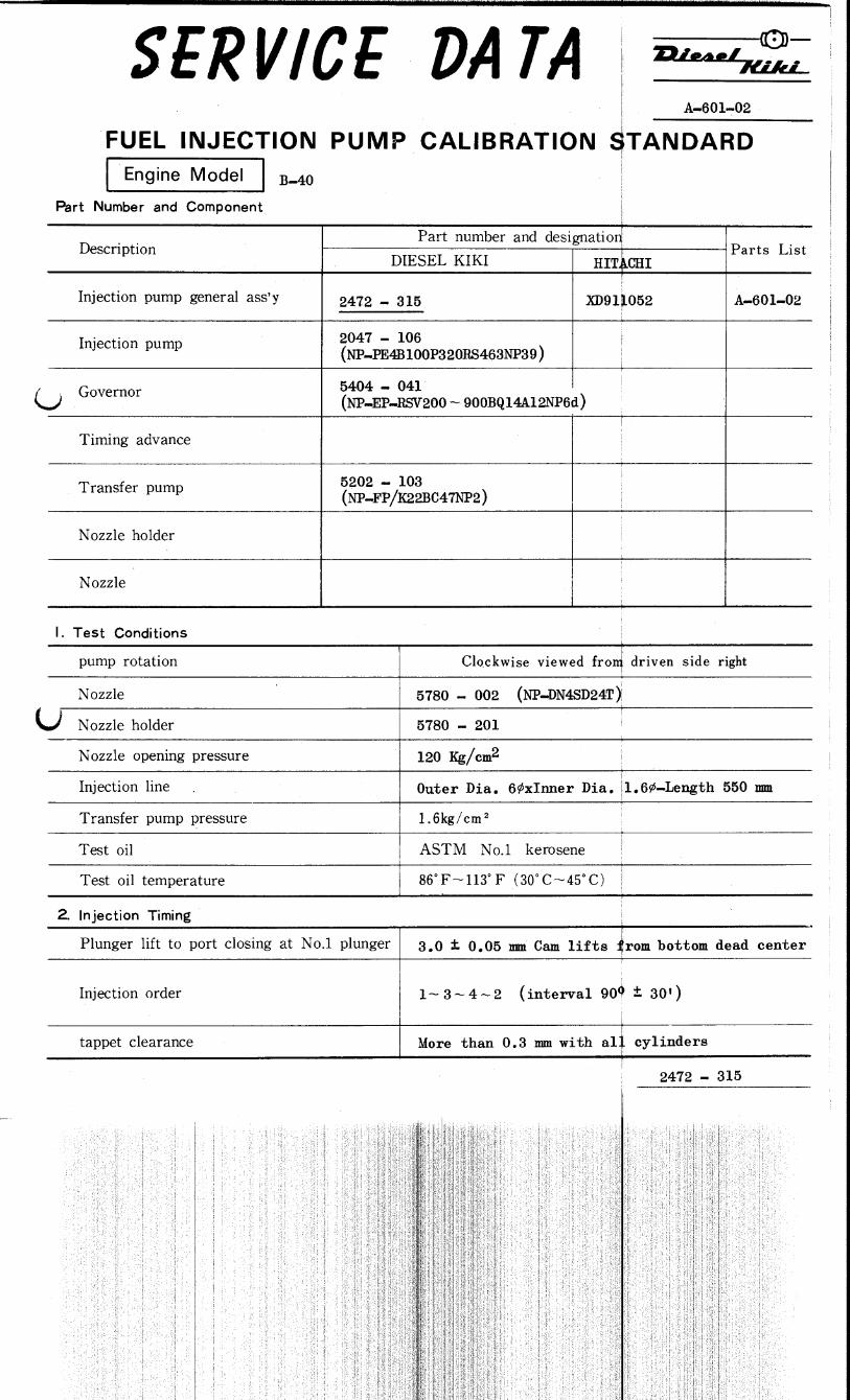
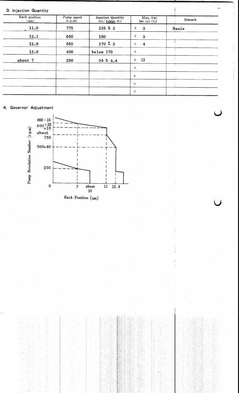
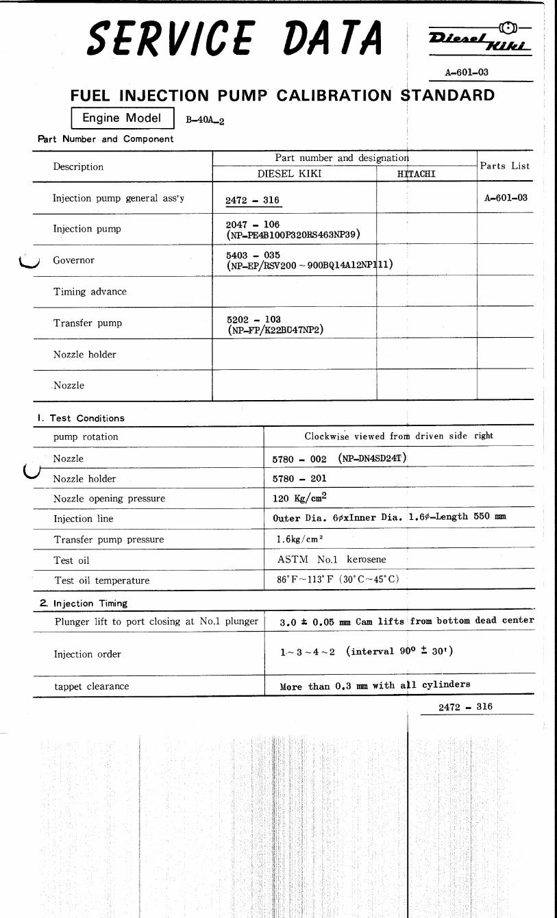
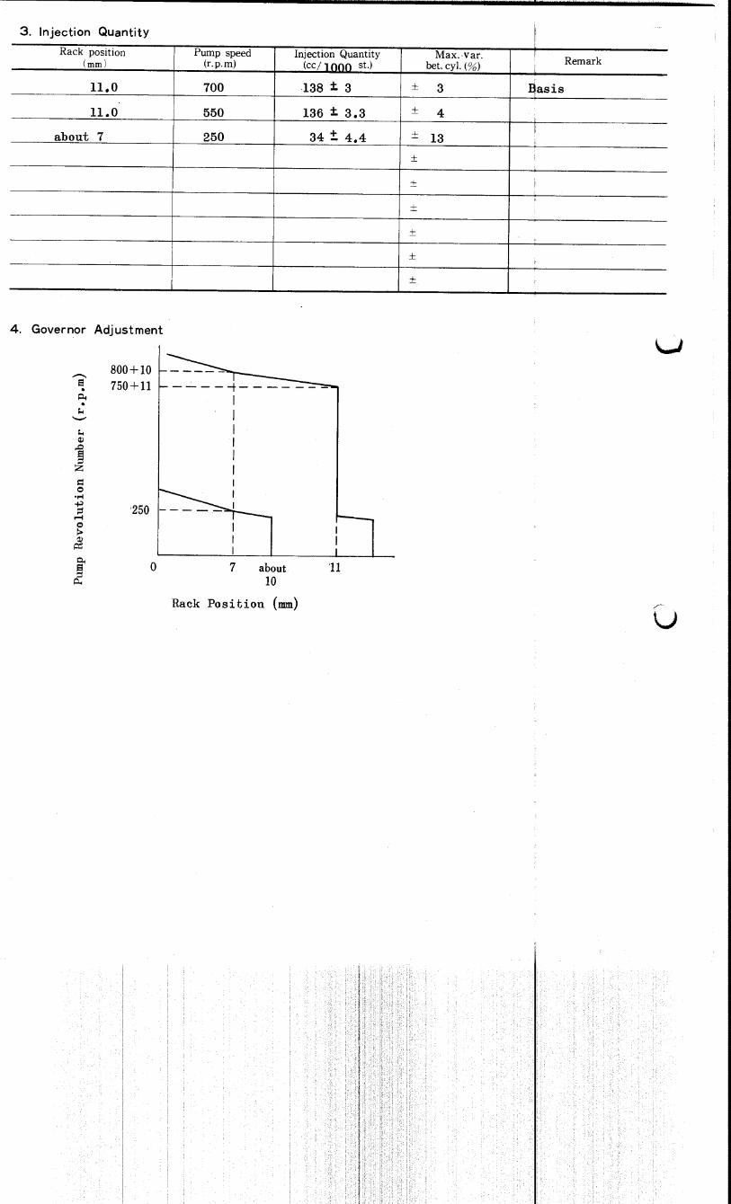
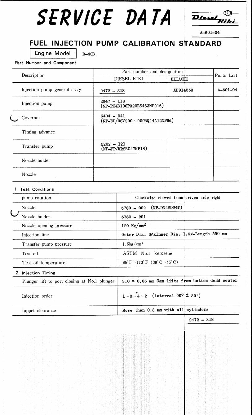


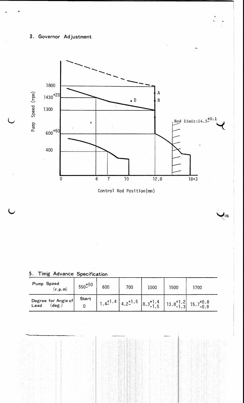
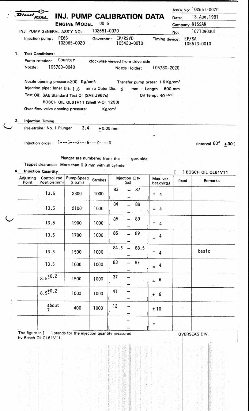
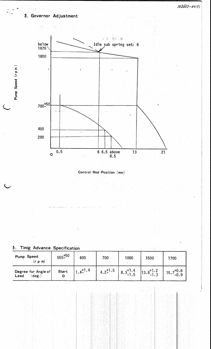
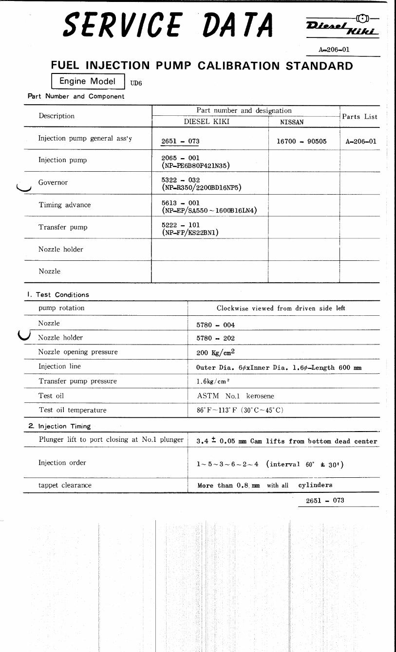
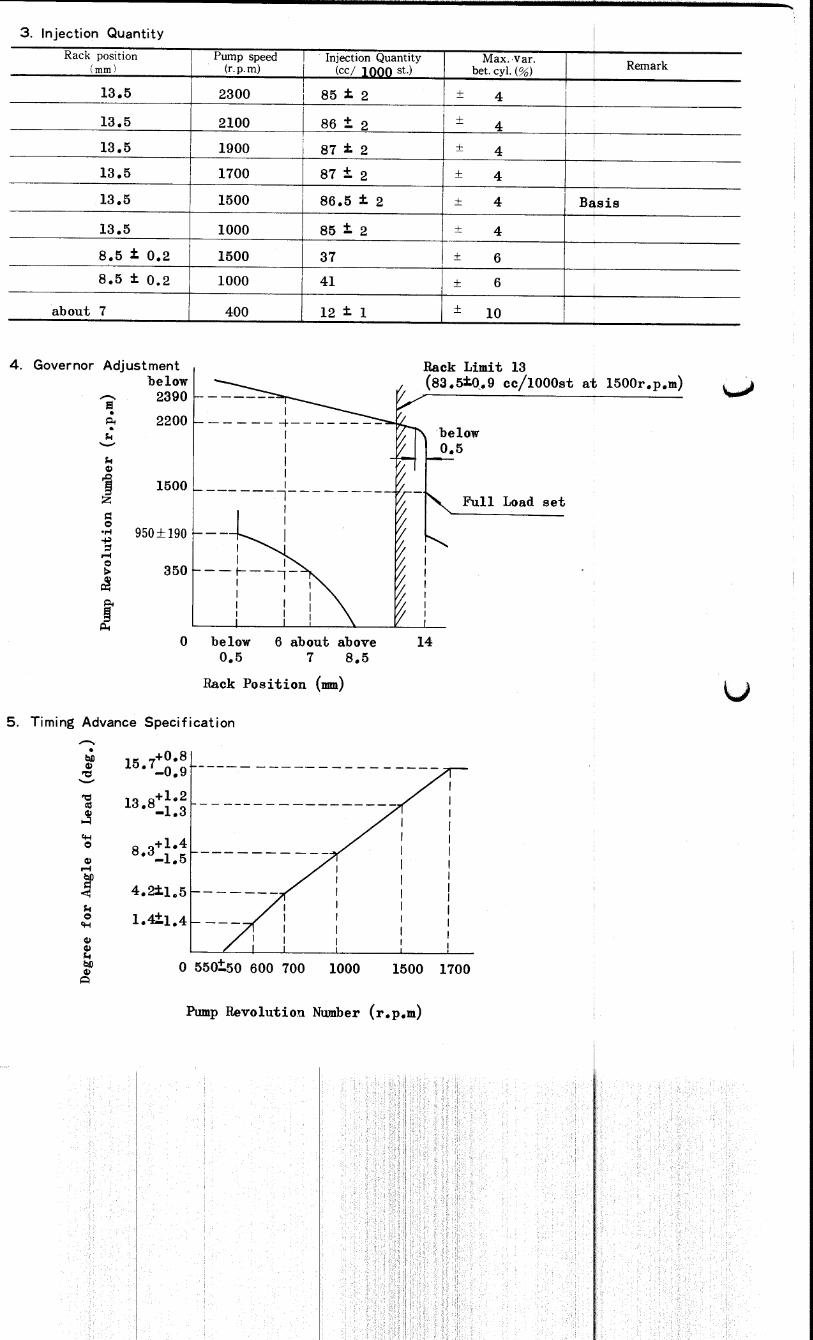
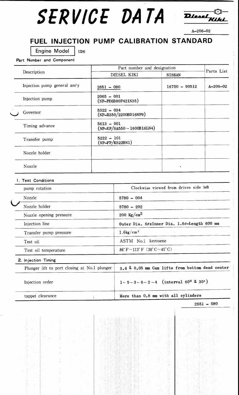
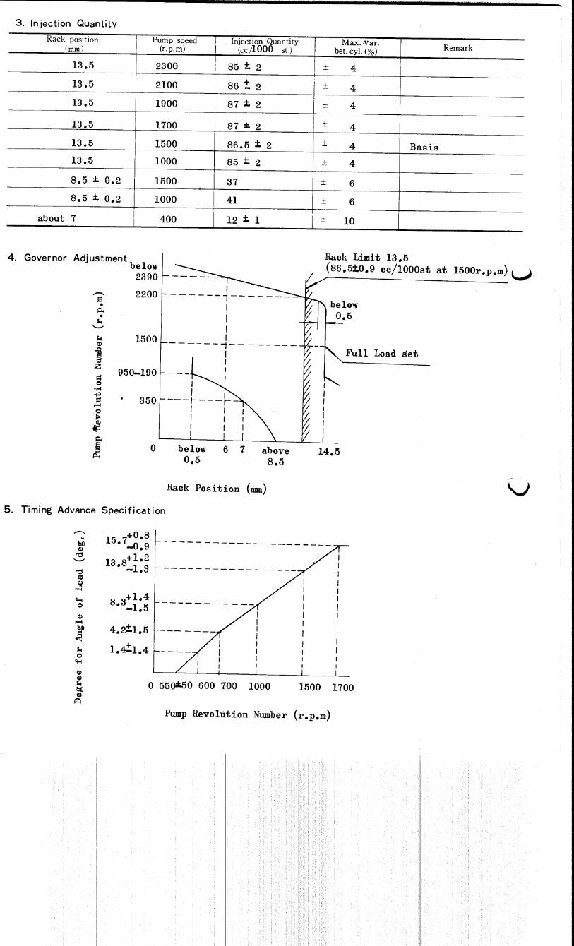
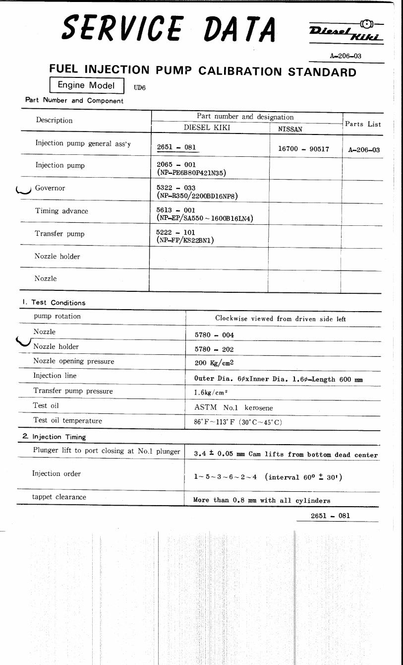
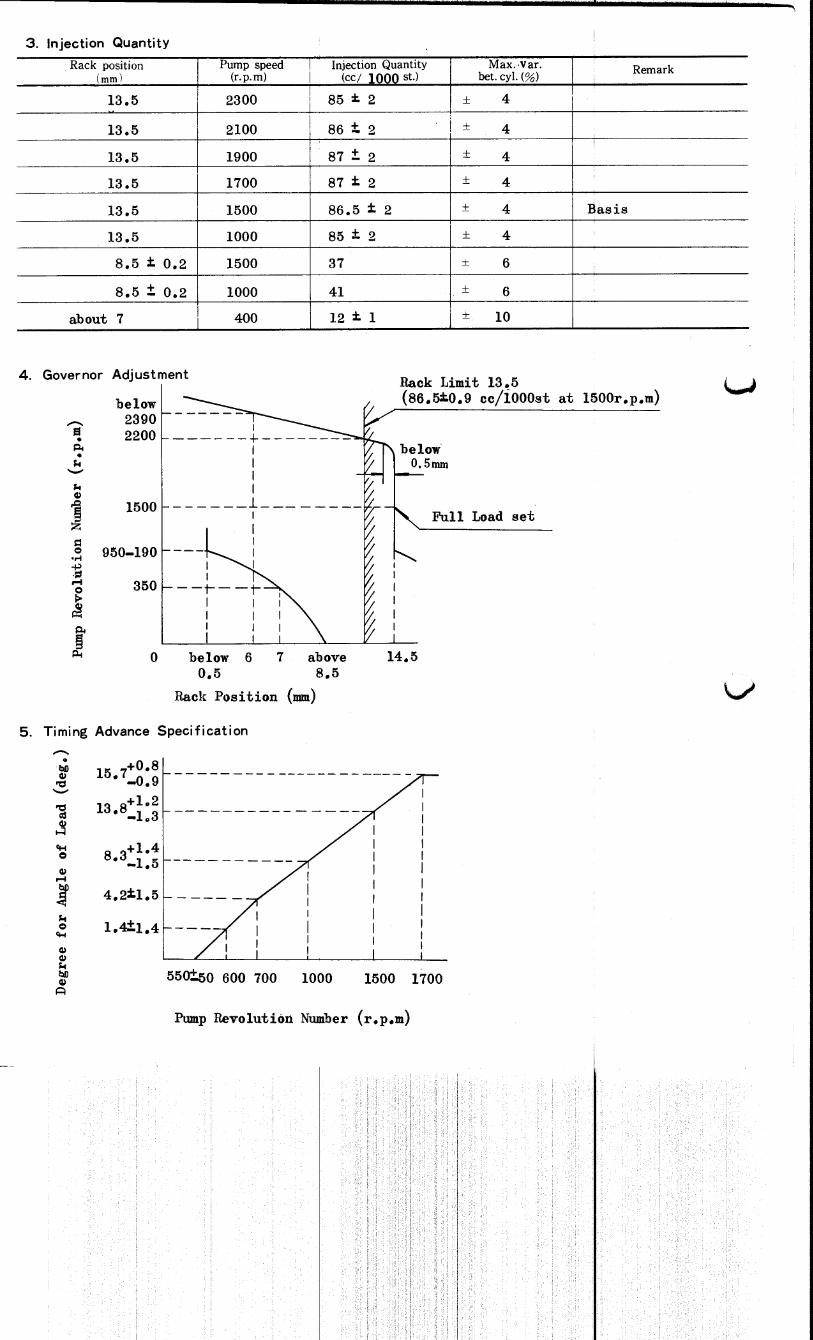
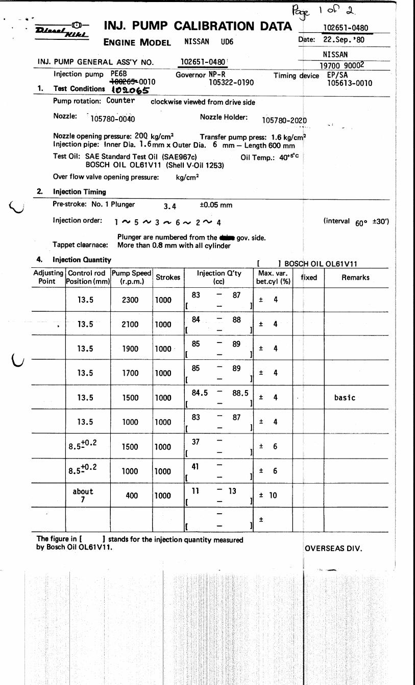
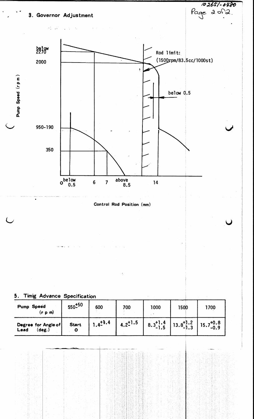
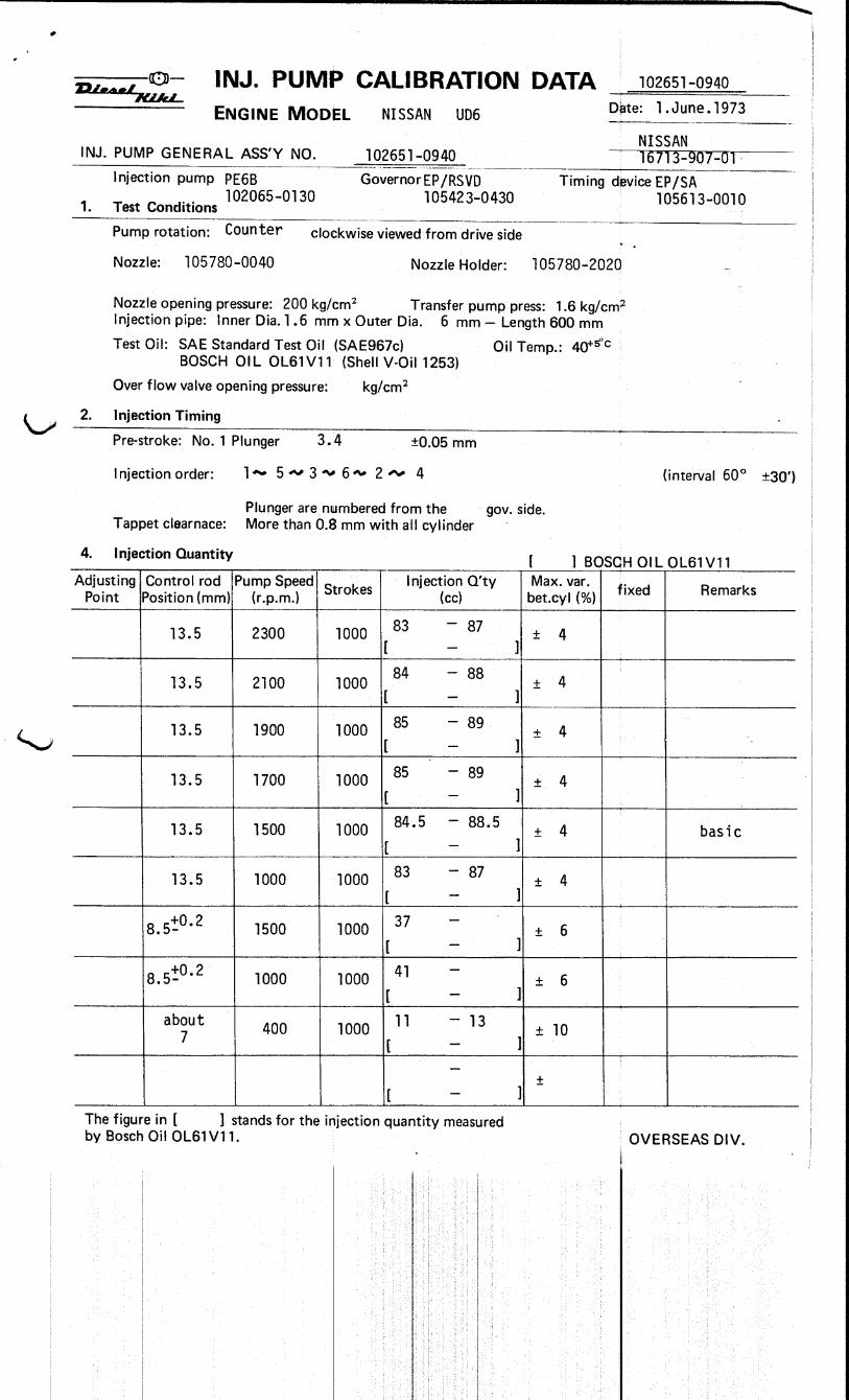

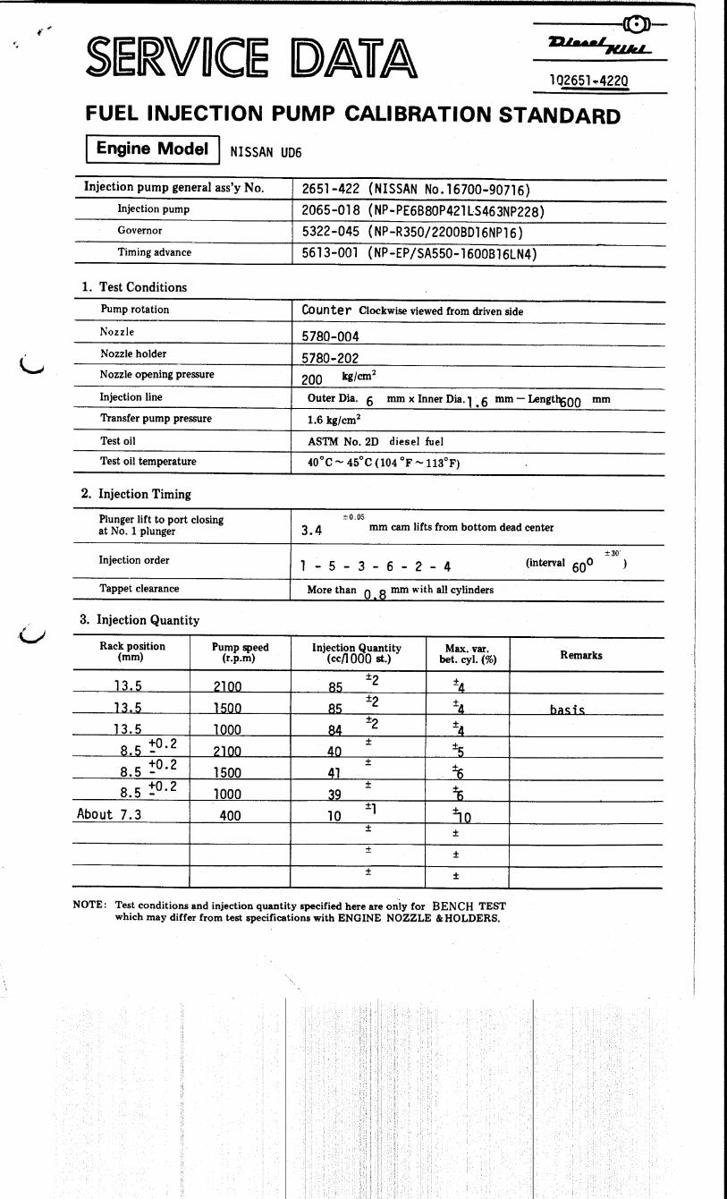
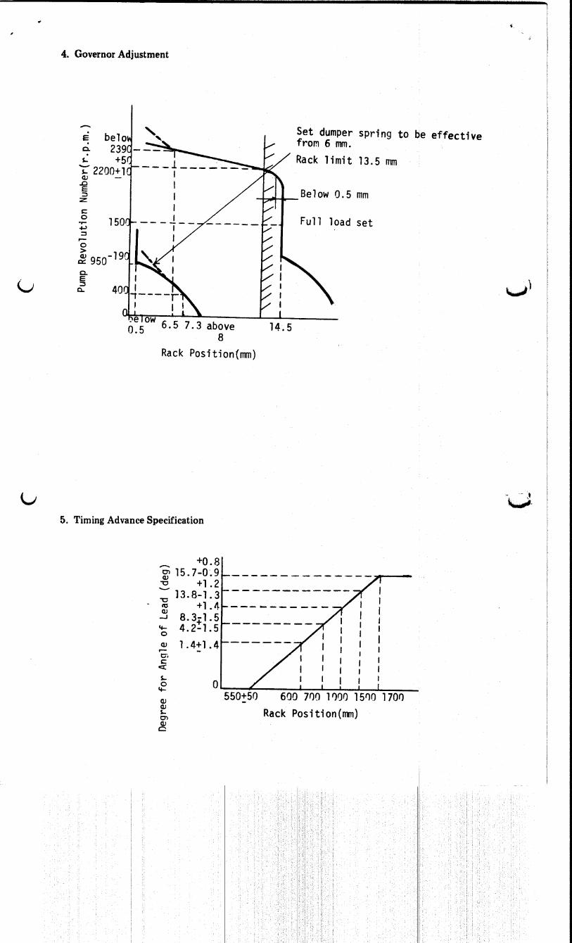
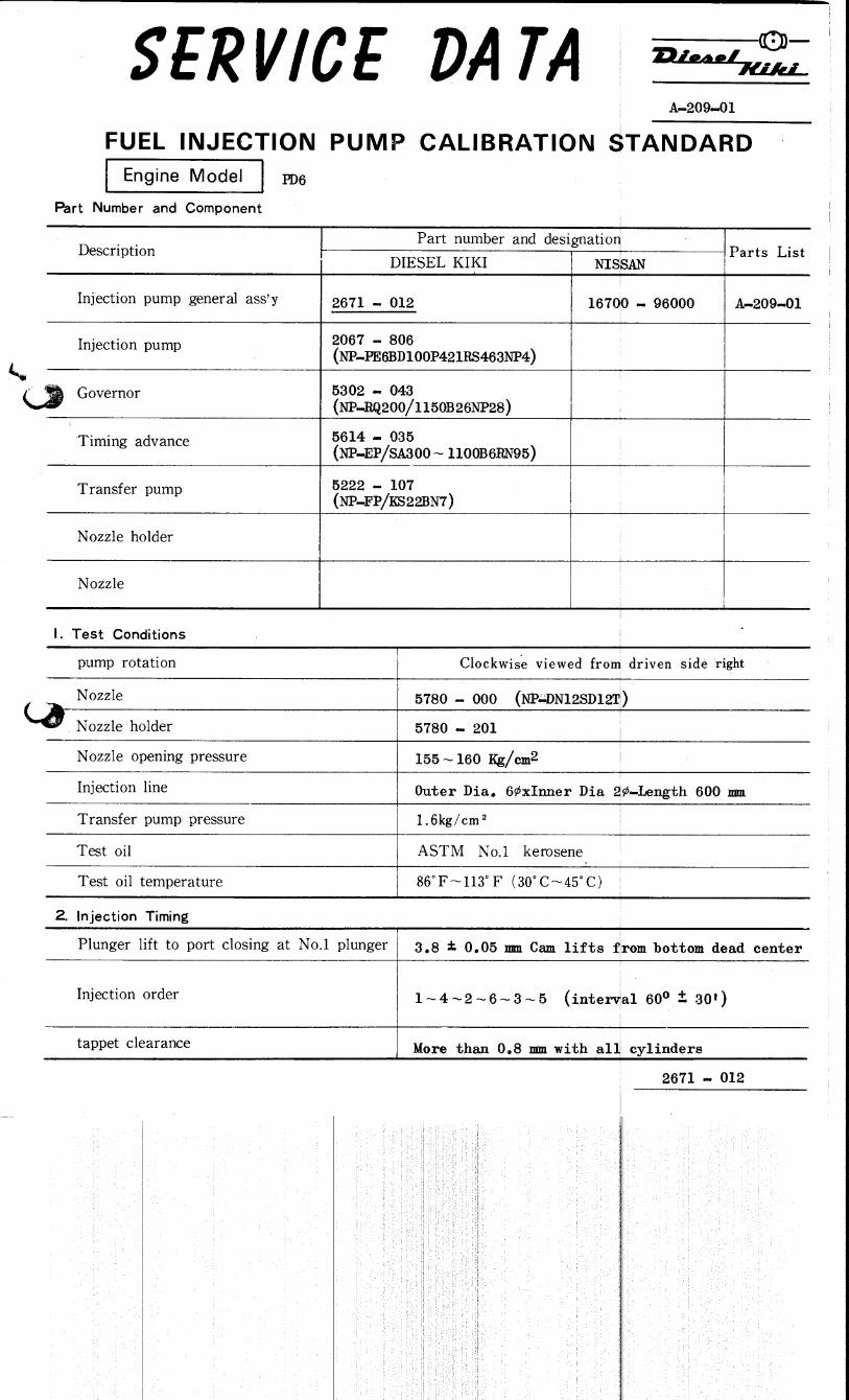
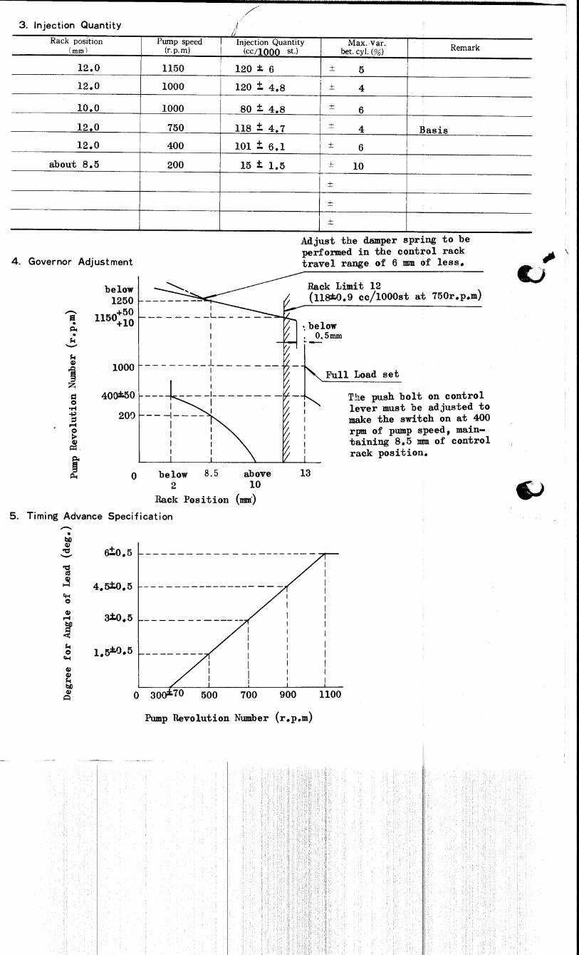
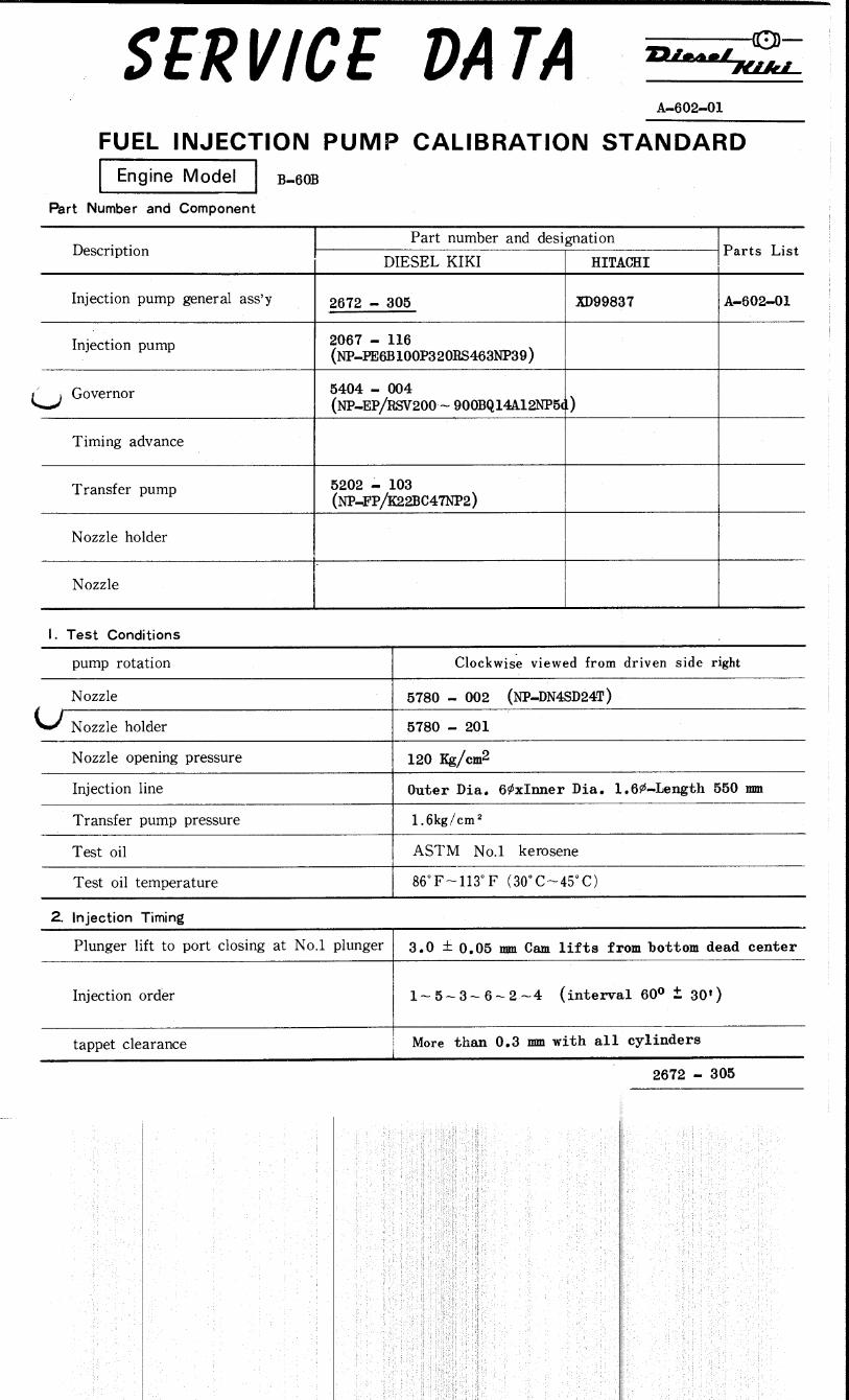
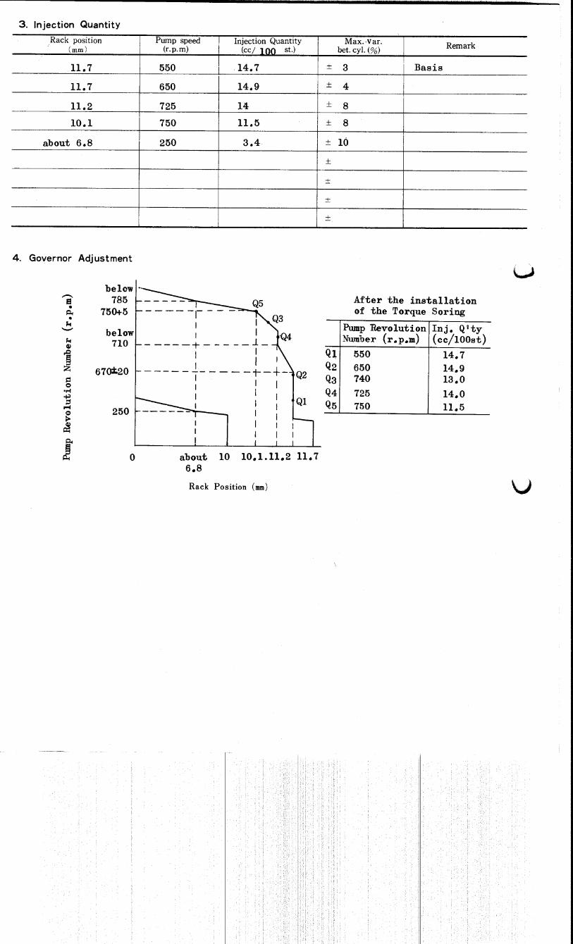
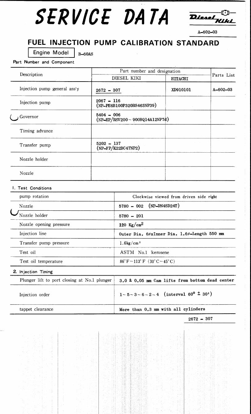
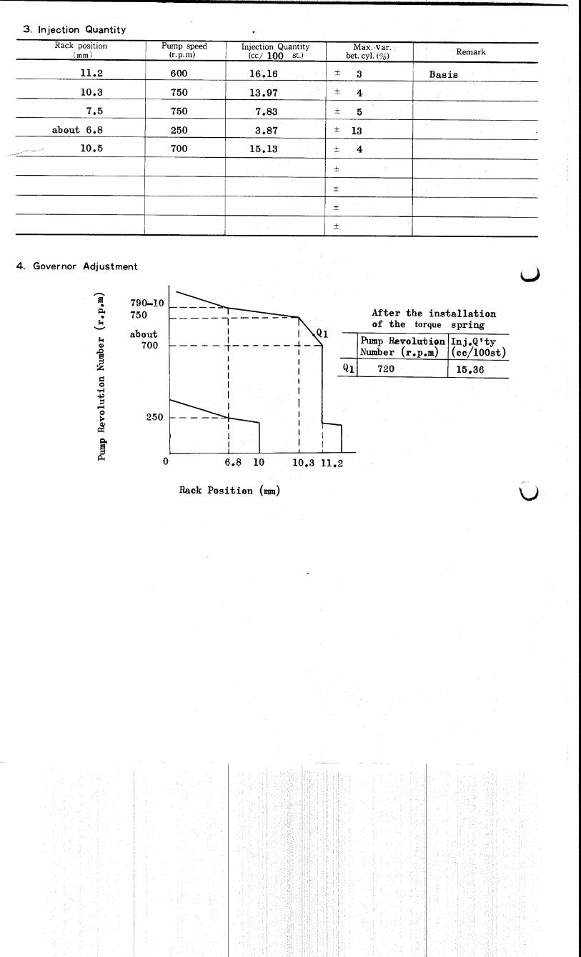
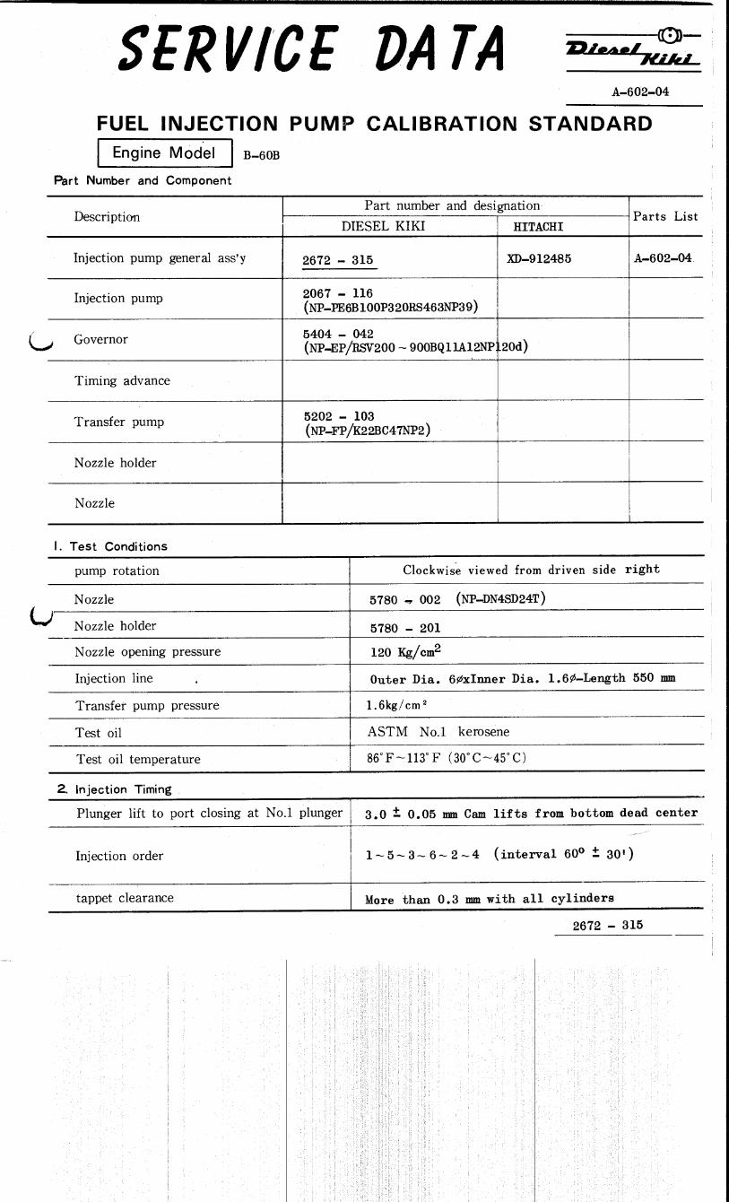

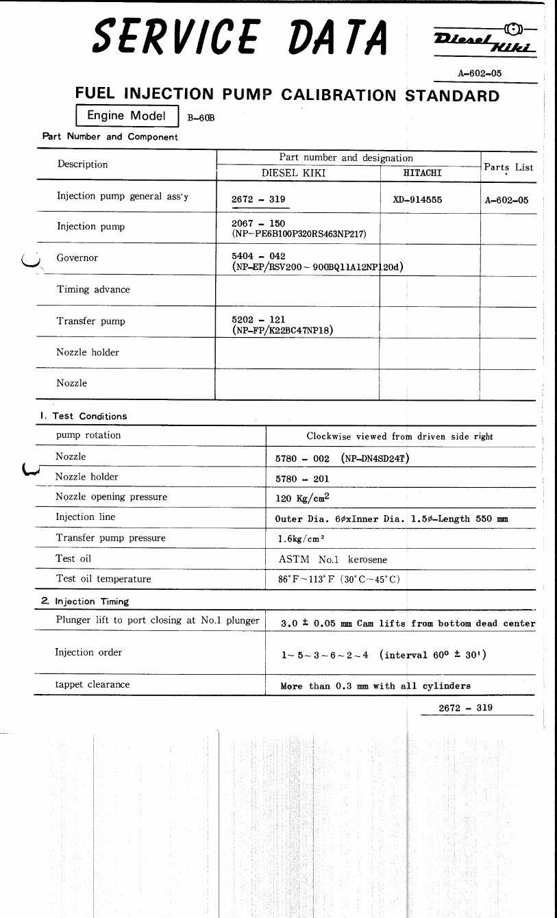
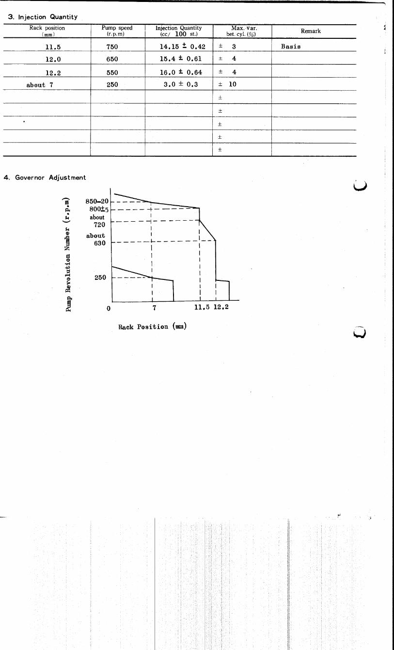
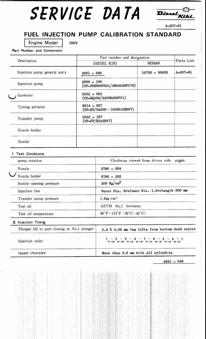

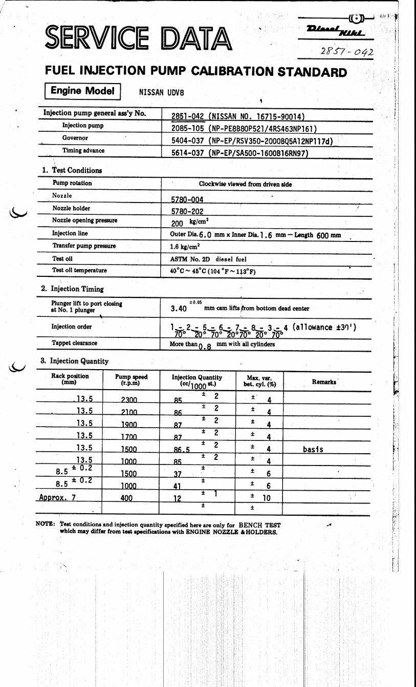
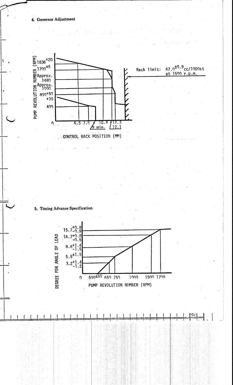
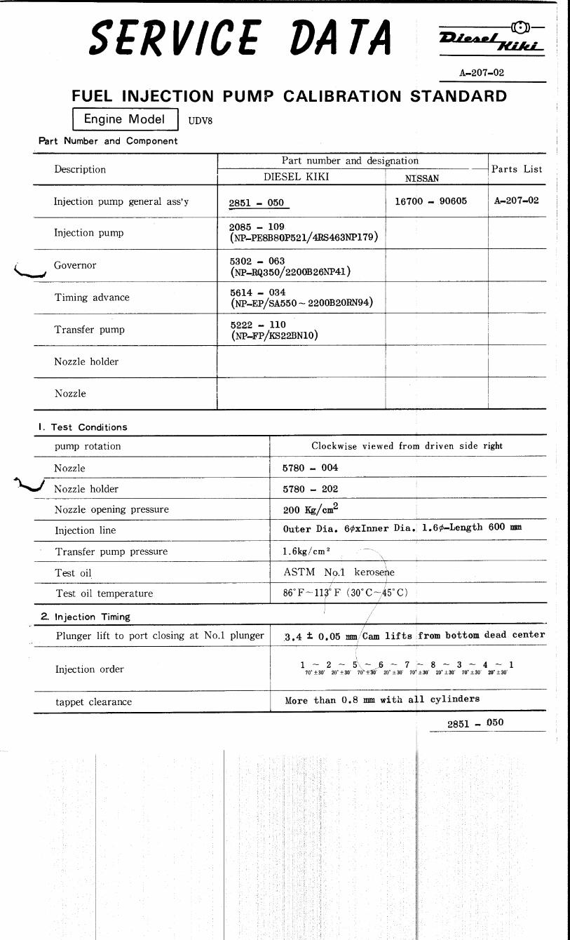
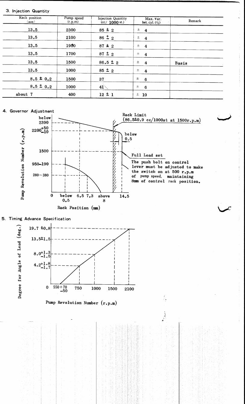
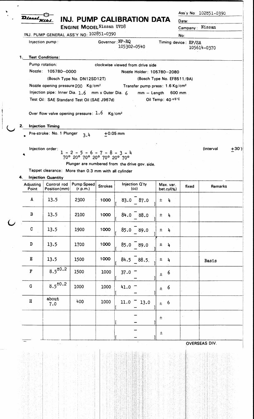
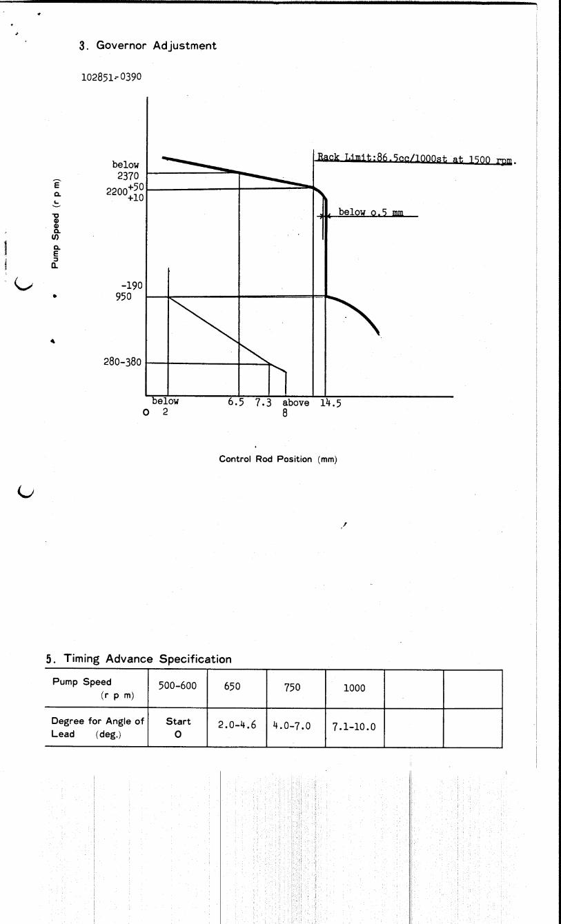
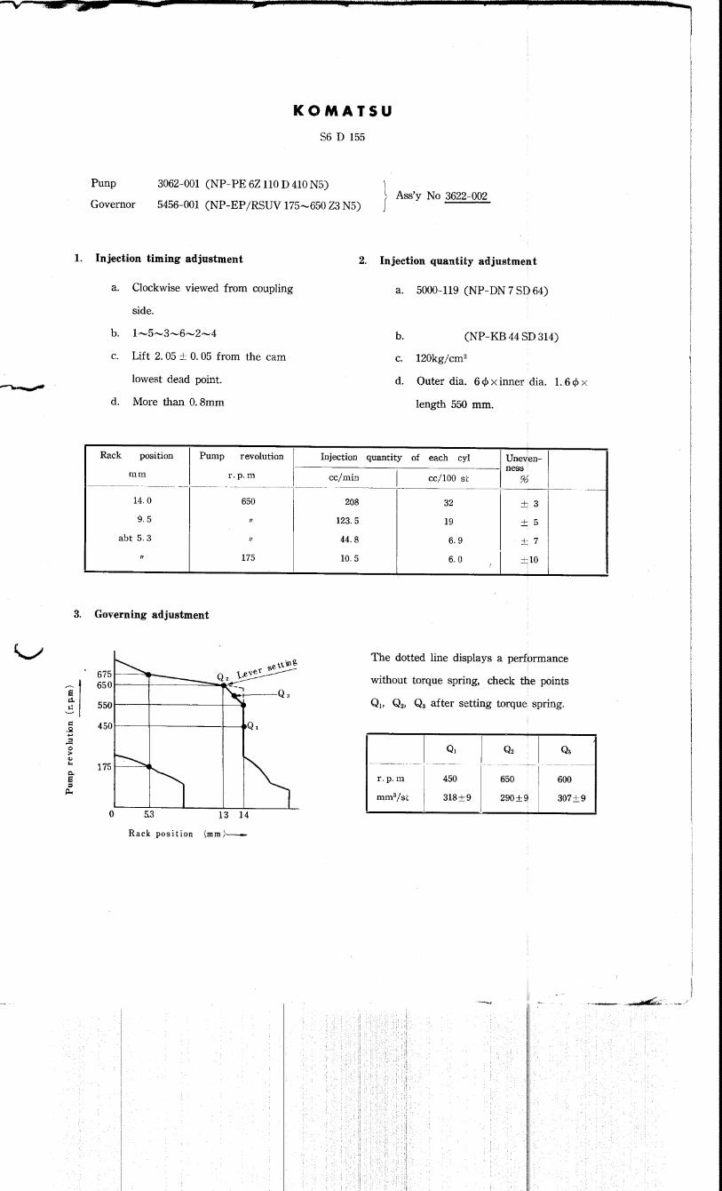
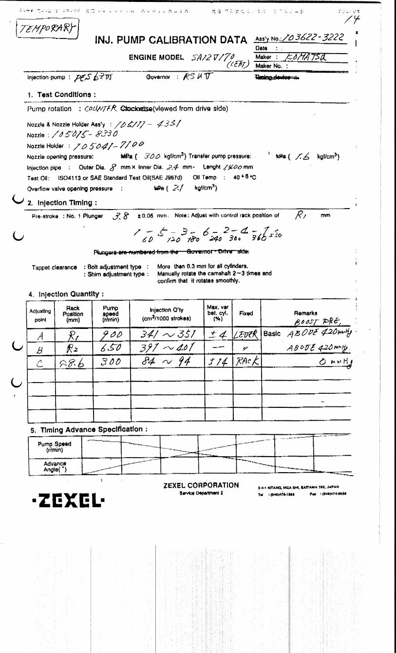
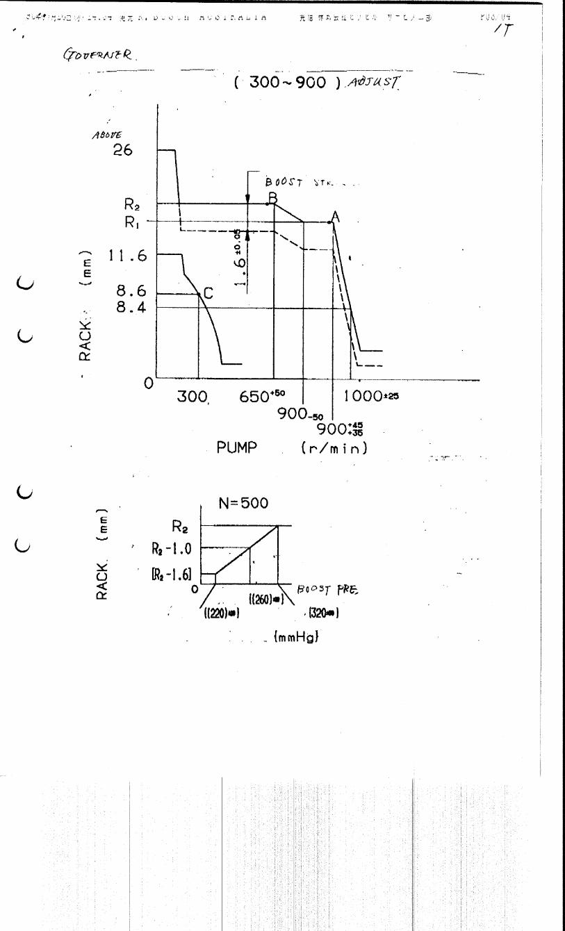


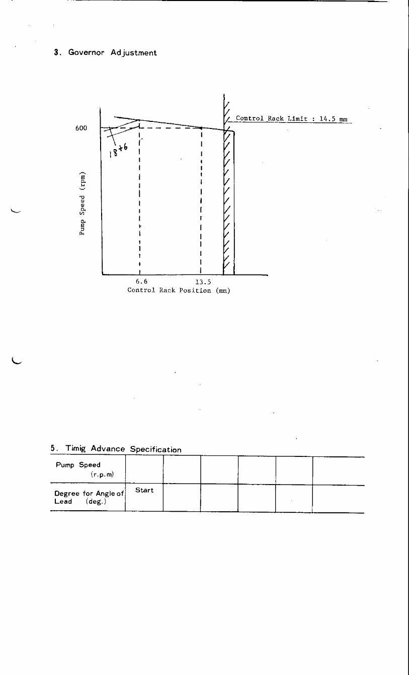
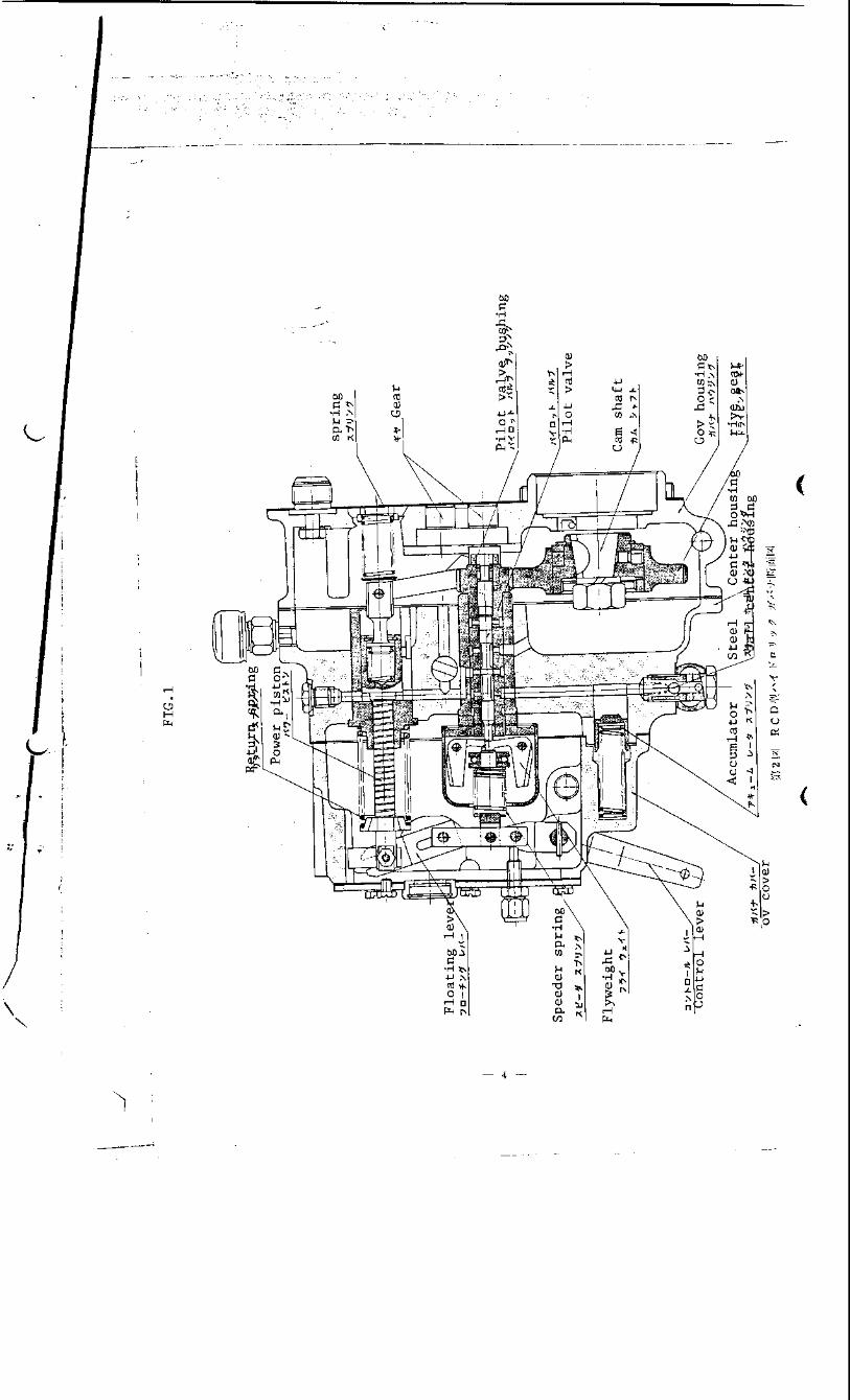
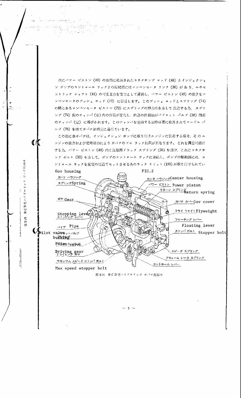
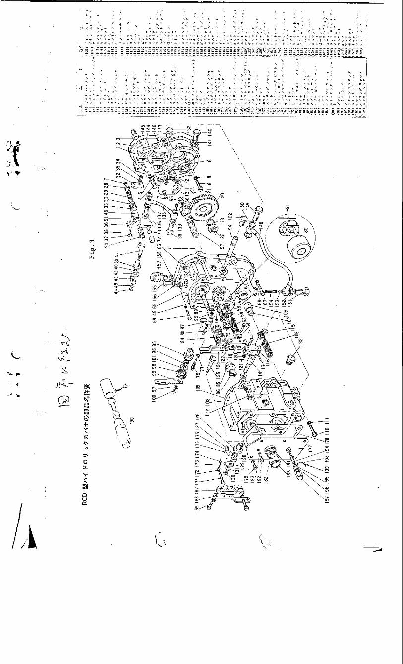
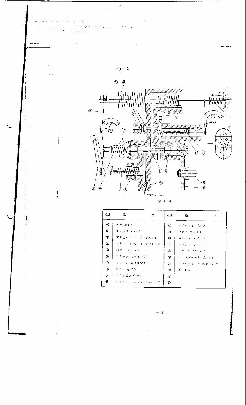
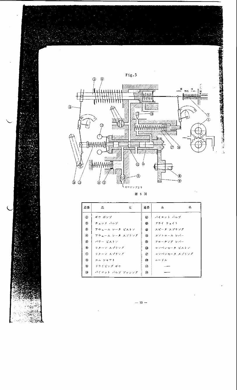

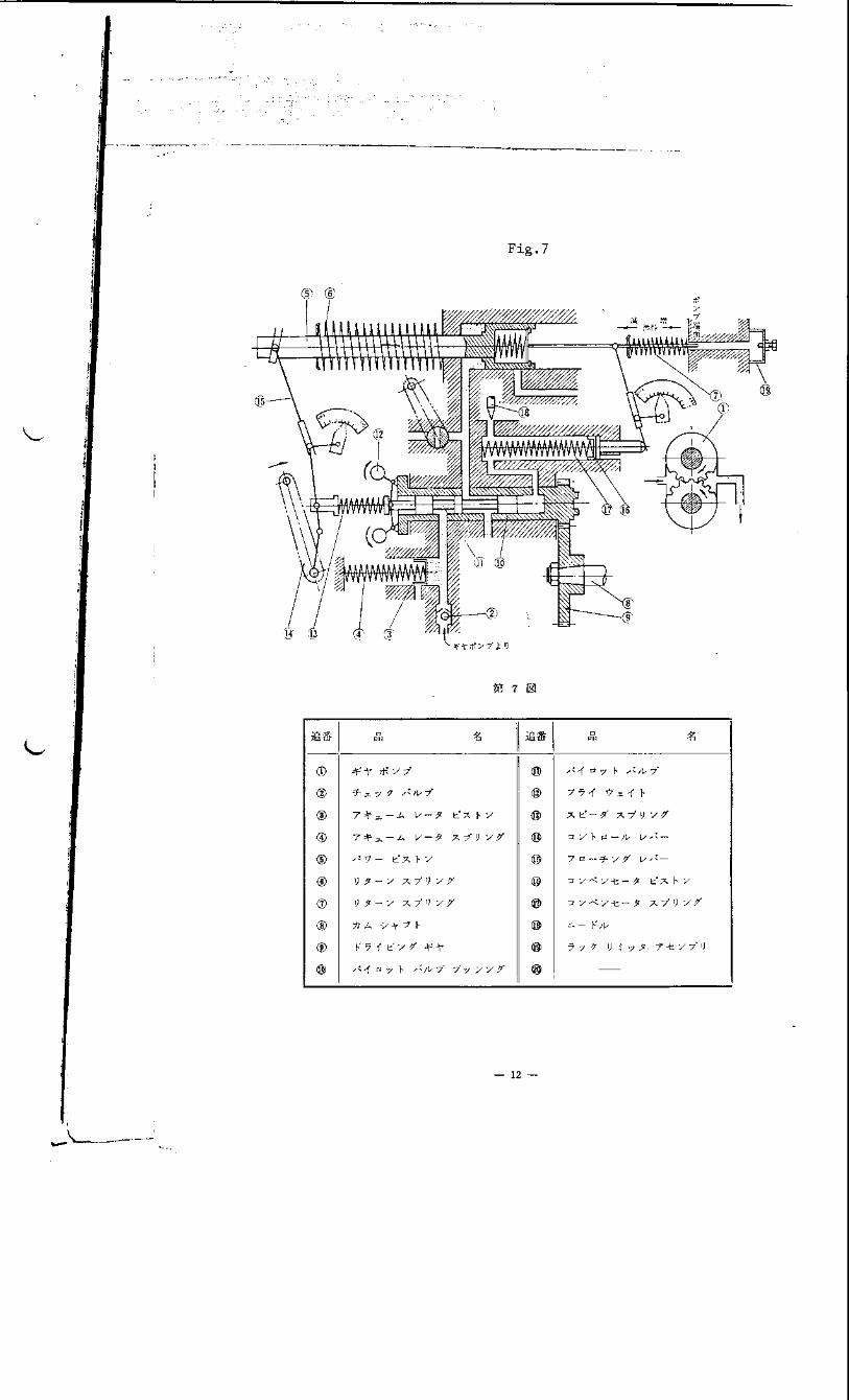
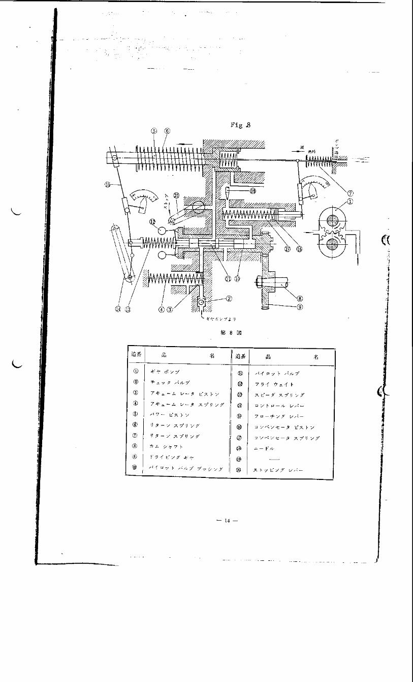
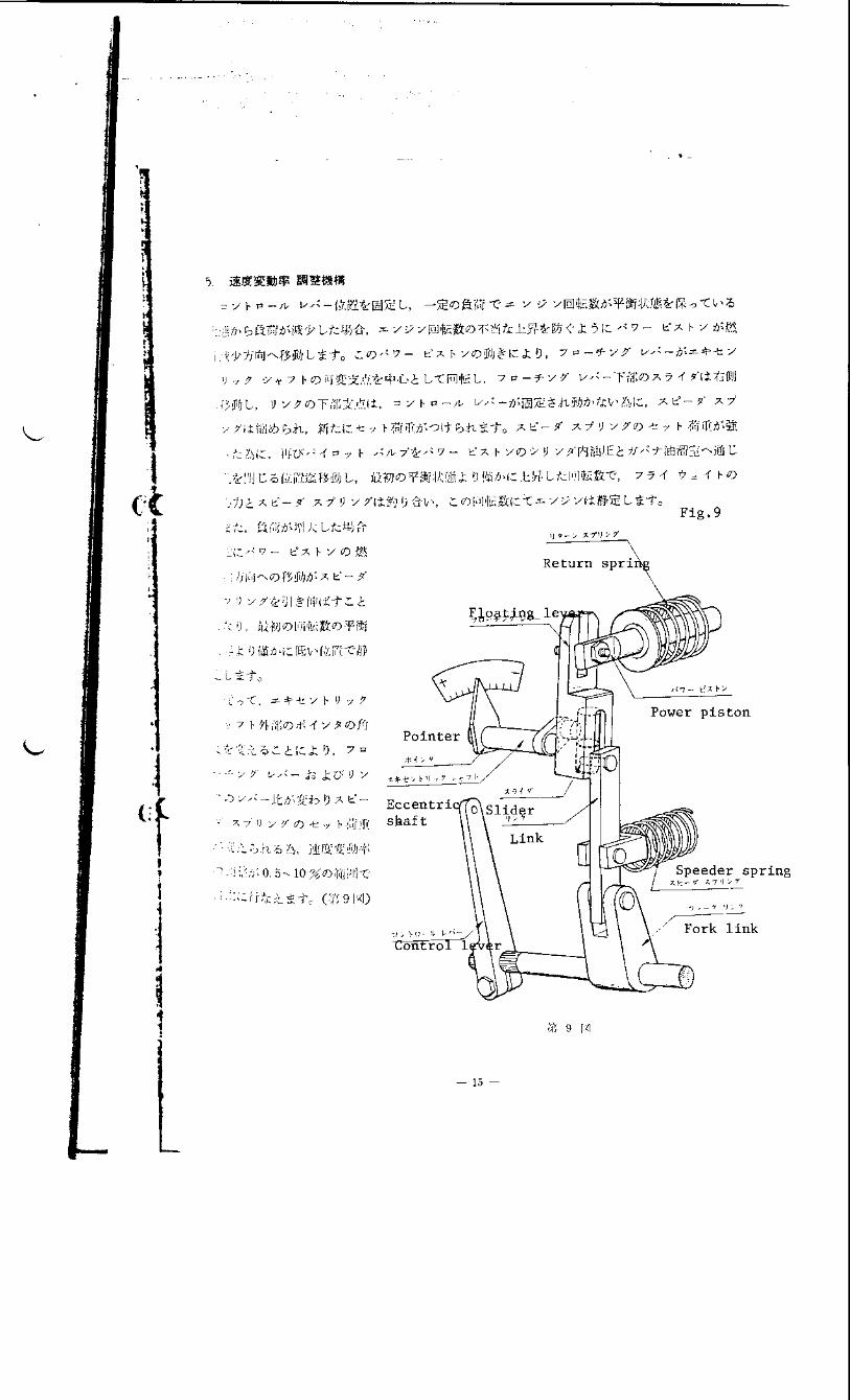
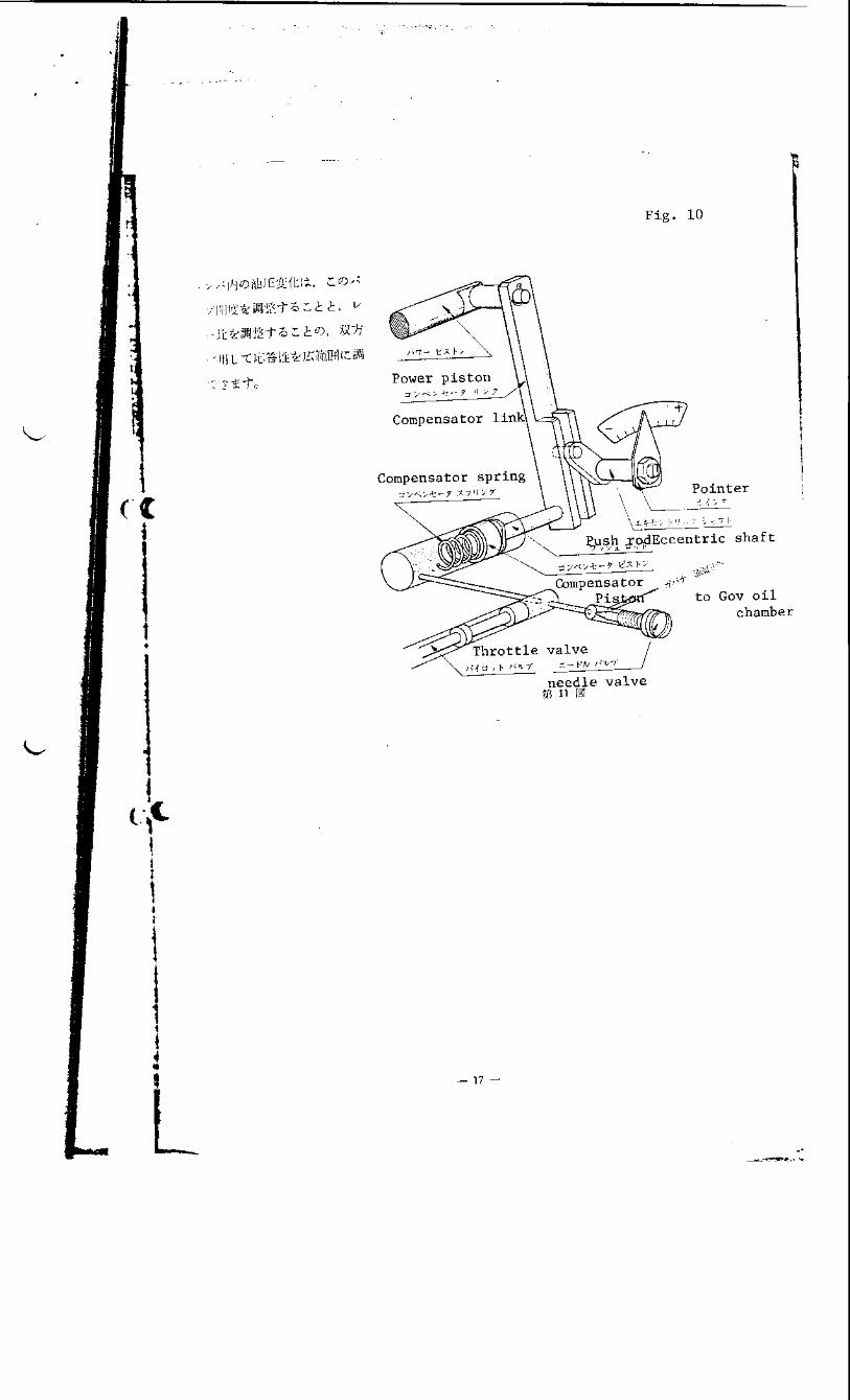
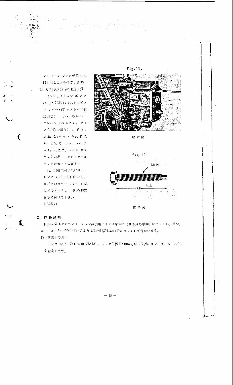
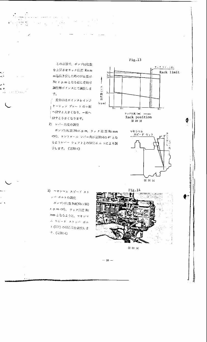
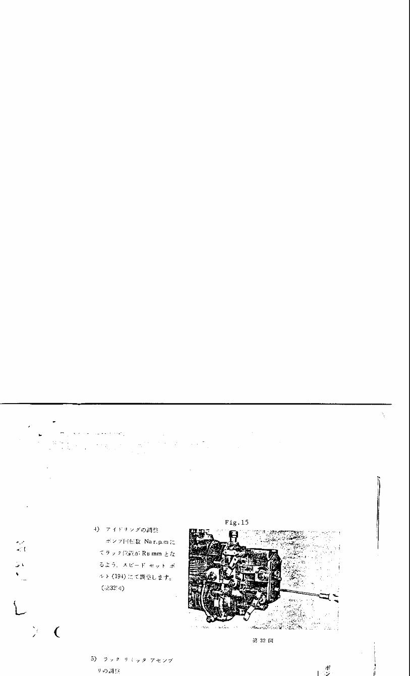
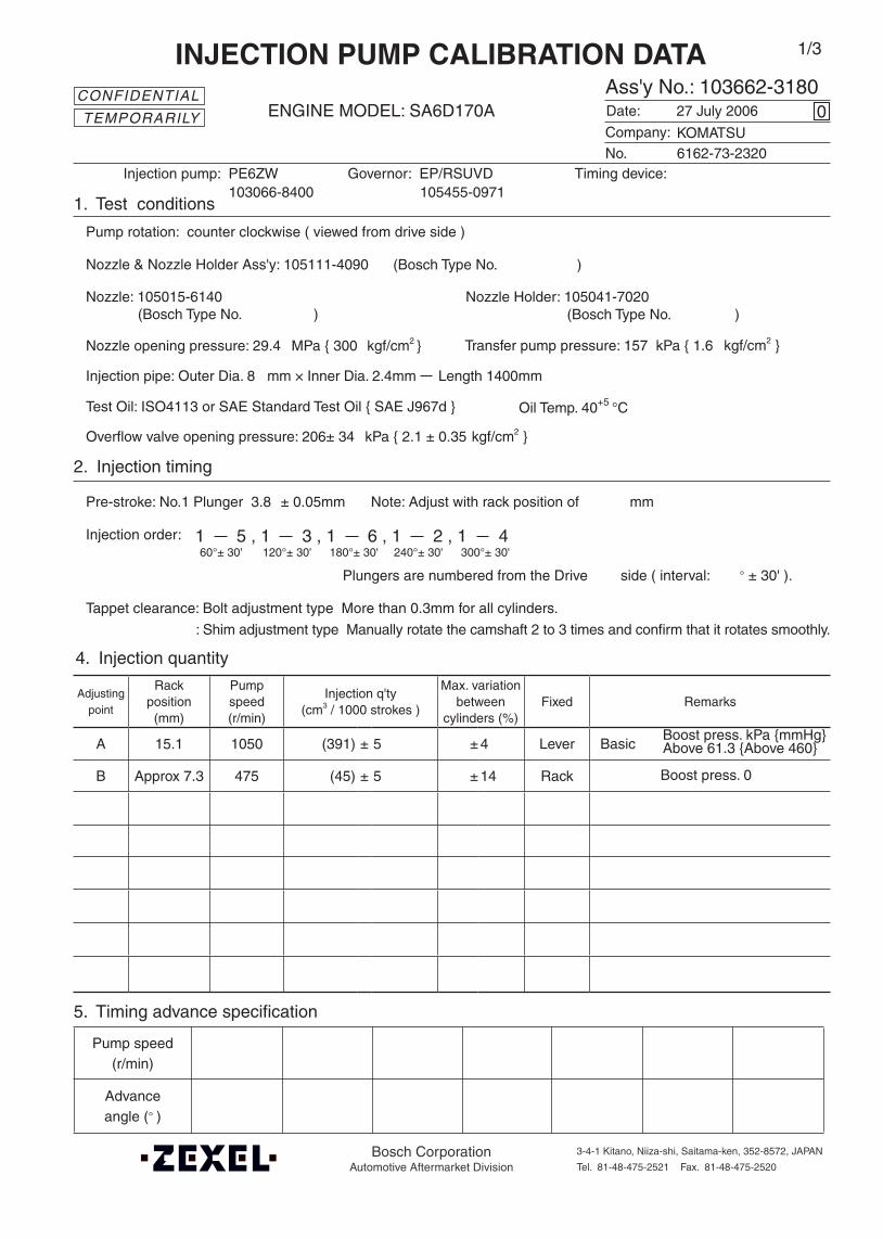
Adjustingpoint
Rackposition
(mm)
Pumpspeed(r/min)
Injection q'ty(cm3 / 1000 strokes )
Max. variationbetween
cylinders (%)Fixed Remarks
A 15.1 1050 (391) ± 5 ± 4 Lever Basic
B Approx 7.3 475 (45) ± 5 ± 14 Rack
Injection order:
Pump speed(r/min)
Advanceangle (° )
4. Injection quantity
5. Timing advance specification
Company:
Ass'y No.: 103662-3180ENGINE MODEL: SA6D170A
No. Governor: EP/RSUVD Timing device:
1. Test conditions
Date:
Pump rotation: counter clockwise ( viewed from drive side )
Injection pump: PE6ZW105455-0971
kgf/cm2 }
2. Injection timing
Pre-stroke: No.1 Plunger 3.8 ± 0.05mm mm
Plungers are numbered from the Drive ° ± 30' ).
Tappet clearance: Bolt adjustment type More than 0.3mm for all cylinders.
: Shim adjustment type Manually rotate the camshaft 2 to 3 times and confirm that it rotates smoothly.
CONFIDENTIAL
INJECTION PUMP CALIBRATION DATA
27 July 2006
6162-73-2320
103066-8400
Injection pipe: Outer Dia. 8 mm × Inner Dia. 2.4mm Length 1400mm
Nozzle opening pressure: 29.4 MPa { 300 kgf/cm2 }
Nozzle: 105015-6140 Nozzle Holder: 105041-7020(Bosch Type No. ) (Bosch Type No. )
Nozzle & Nozzle Holder Ass'y: 105111-4090 (Bosch Type No. )
Overflow valve opening pressure: 206± 34 kPa { 2.1 ± 0.35 kgf/cm2 }
Test Oil: ISO4113 or SAE Standard Test Oil { SAE J967d } Oil Temp. 40+5 °C
side ( interval:
0
Transfer pump pressure: 157 kPa { 1.6
Note: Adjust with rack position of
1 5 , 1 3 , 1 6 , 1 2 , 1 460°± 30' 120°± 30' 180°± 30' 240°± 30' 300°± 30'
KOMATSU
1/3
Boost press. kPa {mmHg}Above 61.3 {Above 460}
Boost press. 0
TEMPORARILY
Bosch CorporationAutomotive Aftermarket Division
3-4-1 Kitano, Niiza-shi, Saitama-ken, 352-8572, JAPAN
Tel. 81-48-475-2521 Fax. 81-48-475-2520
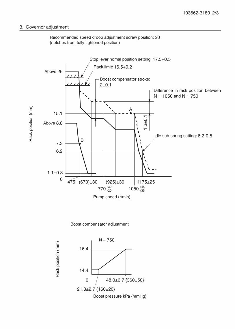
103662-3180 2/3
3. Governor adjustment
Pump speed (r/min)
0475
770 1050
A15.1
Rac
k po
sitio
n (m
m)
6.2
Above 26
1.1±0.3
Recommended speed droop adjustment screw position: 20(notches from fully tightened position)
(670)±30
Boost compensator stroke:2±0.1
16.4
14.4
0
N = 750
Rac
k po
sitio
n (m
m)
Boost pressure kPa {mmHg}
Boost compensator adjustment
B1.
3±0.
1
Difference in rack position between N = 1050 and N = 750
Rack limit: 16.5+0.2
7.3
Above 8.8
+30-20
(925)±30+45+35
1175±25
Stop lever nomal position setting: 17.5+0.5
Idle sub-spring setting: 6.2-0.5
48.0±6.7 {360±50}
21.3±2.7 {160±20}

103662-3180 3/3
Idling
Stopper bolt setting
R=17.5+0.5
Full-load
Speed-control lever angle
Load lever angle
Full-speed
(22°) ±5°
Stop lever angle
Stop Normal
N=0, R=2-0.2
(After lever angle setting,put the seal.)
(After lever angle setting,put the seal.)
(m
easu
re)
±5°
Approx 2
Confirm that the clearance is approx
2mm when contacts inner stopper.
(mea
sure
)±5
°
32° ±5°
15° ±5°

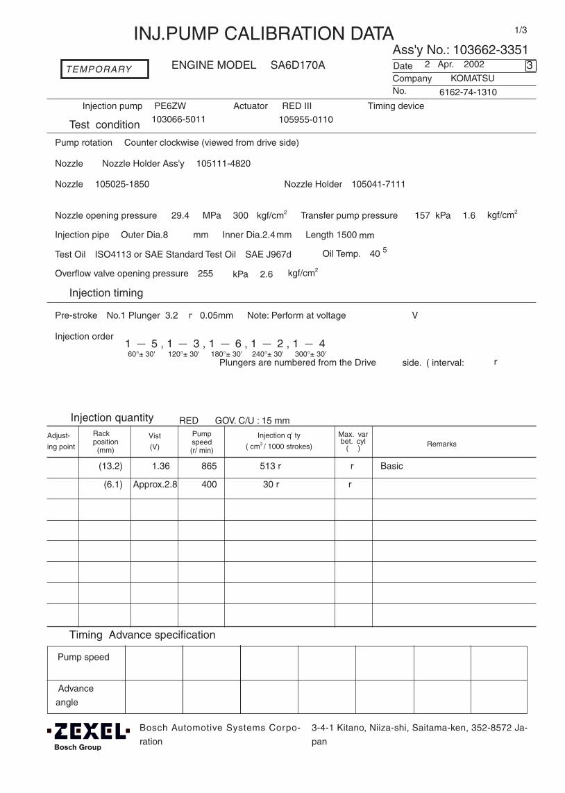
1/3
Ass'y No.: 103662-3351ENGINE MODEL: SA6D170A
No.
Actuator: RED III Timing device:
1.Test condition
Date:
4.Injection quantity
5.Timing Advance specification
Pump speed
Advance
angle(°)
Pump rotation: Counter clockwise (viewed from drive side)
Injection pump: PE6ZW
kgf/cm2}
2.Injection timing
Pre-stroke:No.1 Plunger 3.2 ± 0.05mm Note: Perform at voltage
V
Injection order:
Plungers are numbered from the Drive °± )
(13.2) 1.36 865 513 ± 5 ± 4 Basic
INJ.PUMP CALIBRATION DATA
Company:
2 Apr. 2002
KOMATSU
6162-74-1310
103066-5011
Injection pipe: Outer Dia.8 mm × Inner Dia.2.4mm - Length 1500 mm
Nozzle opening pressure: 29.4 MPa{ 300 kgf/cm2} Transfer pump pressure: 157 kPa{ 1.6
Nozzle: 105025-1850 Nozzle Holder:105041-7111
Nozzle & Nozzle Holder Ass'y :105111-4820
Overflow valve opening pressure:255 kPa{ 2.6 kgf/cm2}
Test Oil:ISO4113 or SAE Standard Test Oil{SAE J967d} Oil Temp.:40 ℃+5
side. ( interval:
Adjust-
ing point
Rackposition (mm)
Pumpspeed(r/ min)
Max. varbet. cyl
(% ) Remarks
3
Bosch Automotive Systems Corpo-
ration
3-4-1 Kitano, Niiza-shi, Saitama-ken, 352-8572 Ja-
pan
105955-0110
RED Ⅲ GOV. C/U : 15 mm
Injection q' ty
( cm3 / 1000 strokes)Vist
(V)
1 5 , 1 3 , 1 6 , 1 2 , 1 460°± 30' 120°± 30' 180°± 30' 240°± 30' 300°± 30'
TEMPORARY
(6.1) Approx.2.8 400 30 ± 5 ± 14
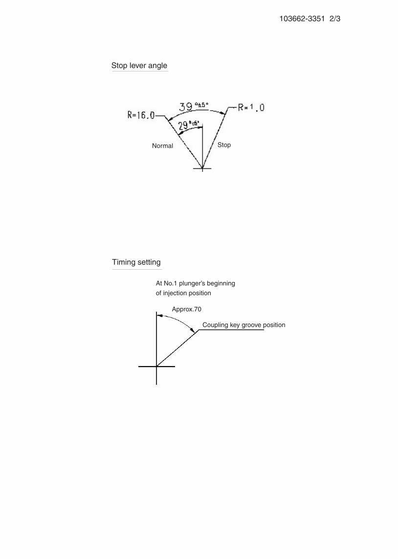
103662-3351 2/3
At No.1 plunger’s beginning
of injection position
Timing setting
Approx.70°
Coupling key groove position
Stop lever angle
StopNormal
103662-3351 3/3
■ RED Ⅲ governor
Confirmation of the control rack position sensor's output characteristics
(Rack 15mm , Span 6mm)
When the rack sensor output voltages are V1 and V2, confirm that rack positions R1
and R2 are as specified below.
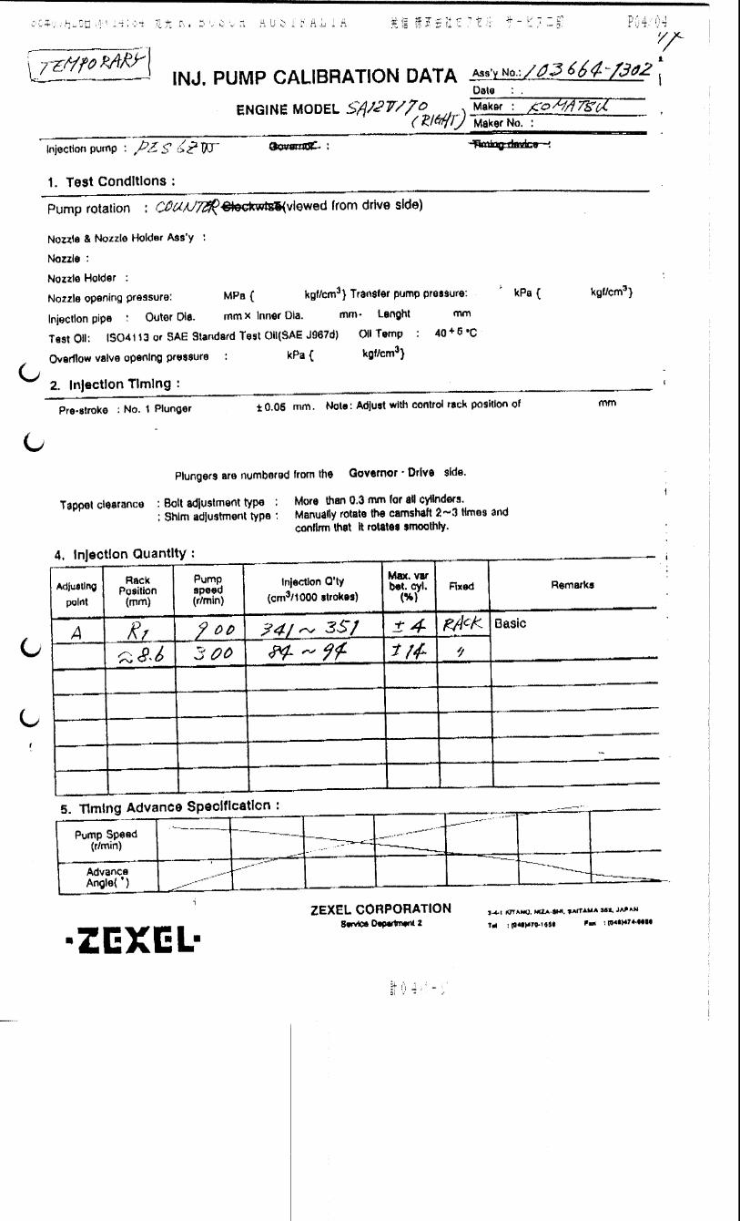
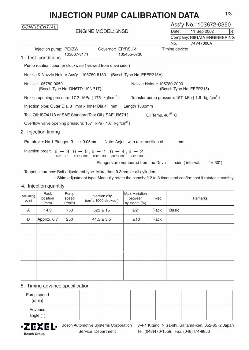
Adjustingpoint
Rackposition
(mm)
Pumpspeed(r/min)
Injection q'ty(cm3 / 1000 strokes )
Max. variationbetween
cylinders (%)Fixed Remarks
A 14.3 750 523 ± 15 ± 2 Rack Basic
B Approx. 6.7 250 41.5 ± 3.5 ± 10 Rack
Injection order:
Pump speed(r/min)
Advanceangle (° )
4. Injection quantity
5. Timing advance specification
Bosch Automotive Systems Corporation
Service Department
3-4-1 Kitano, Niiza-shi, Saitama-ken, 352-8572 Japan
Tel. (048)470-1559, Fax. (048)474-9856
Company:
Ass'y No.: 103672-0350ENGINE MODEL: 6NSD
No. Governor: EP/RSUV Timing device:
1. Test conditions
Date:
Pump rotation: counter clockwise ( viewed from drive side )
Injection pump: PE6ZW105455-0730
kgf/cm2 }
2. Injection timing
Pre-stroke: No.1 Plunger 3 ± 0.05mm mm
Plungers are numbered from the Drive ° ± 30' ).
Tappet clearance: Bolt adjustment type More than 0.3mm for all cylinders.
: Shim adjustment type Manually rotate the camshaft 2 to 3 times and confirm that it rotates smoothly.
CONFIDENTIAL
INJECTION PUMP CALIBRATION DATA
11 Sep 2002
NIIGATA ENGINEERING74V47000A
103067-8171
Injection pipe: Outer Dia. 8 mm × Inner Dia.4 mm Length 1500mm
Nozzle opening pressure: 17.2 MPa { 175 kgf/cm2 }
Nozzle: 105780-0050 Nozzle Holder: 105780-2090(Bosch Type No. DN6TD119NP1T) (Bosch Type No. EFEP215)
Nozzle & Nozzle Holder Ass'y: 105780-8130 (Bosch Type No. EFEP215A)
Overflow valve opening pressure: 157 kPa { 1.6 kgf/cm2 }
Test Oil: ISO4113 or SAE Standard Test Oil { SAE J967d } Oil Temp. 40+5 °C
side ( interval:
3
Transfer pump pressure: 157 kPa { 1.6
Note: Adjust with rack position of
1/3
6 3 , 6 5 , 6 1 , 6 4 , 6 260°± 30' 120°± 30' 180°± 30' 240°± 30' 300°± 30'

103672-0350 2/3
5. Timing advance specification
Adjust the clearance between the pickup and the gear tooth to 1-0.2mm.
3. Governor adjustment
Above 26
6.7
0 235Below 815
A
BRac
k po
sitio
n (m
m)
Pump speed (r/min)
Rack limit: 21+1
Recommended speed droop adjustment screw position: 19(notches from fully tightened position)
14.39.0
5.7
250 750±5
Do not adjust idling spring
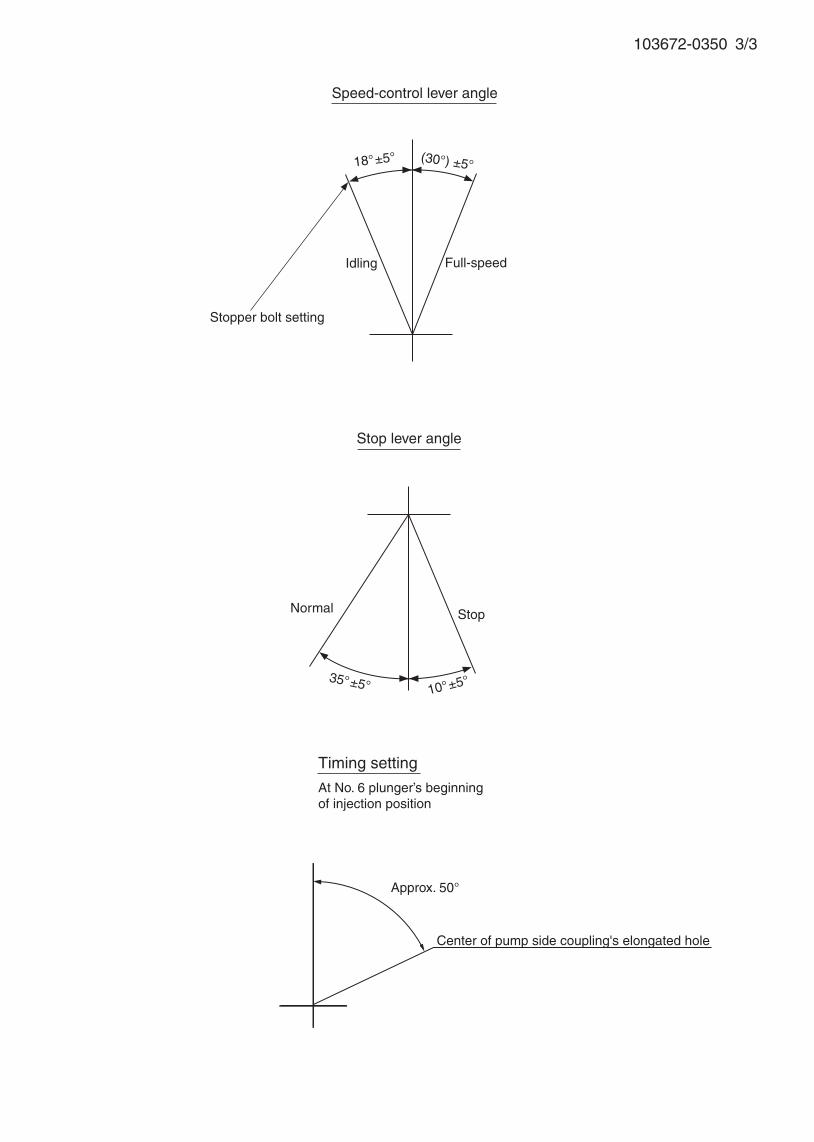
103672-0350 3/3
35°±5°
Speed-control lever angle
Idling
Stopper bolt setting
Stop lever angle
Stop
Full-speed
Normal
(30°) ±5°18°±5°
10°±5°
Timing setting
At No. 6 plunger’s beginning of injection position
Approx. 50°
Center of pump side coupling's elongated hole
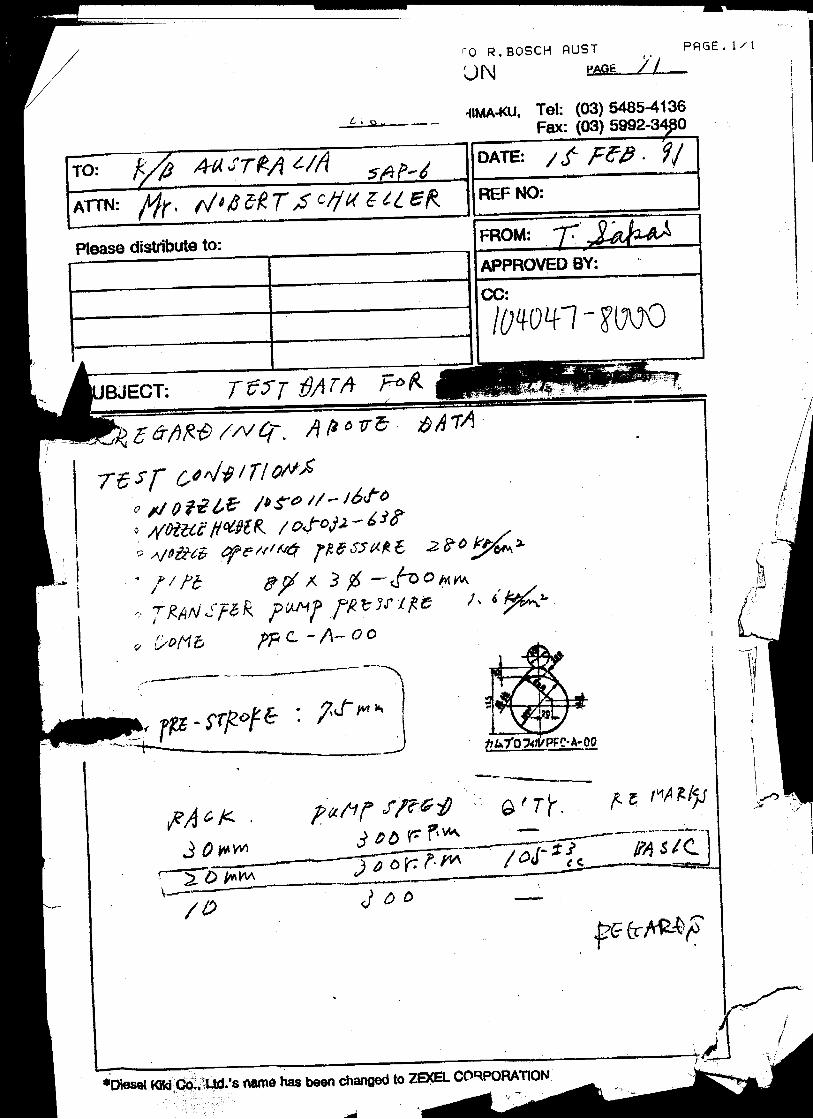
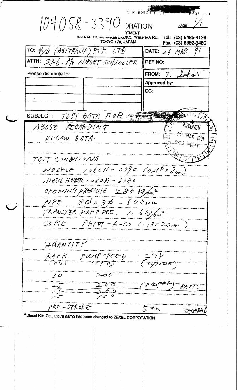
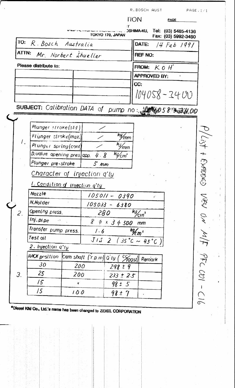
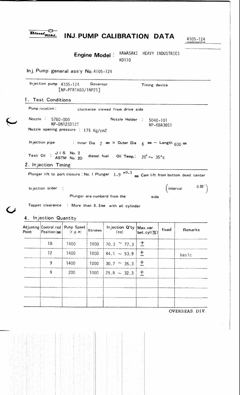

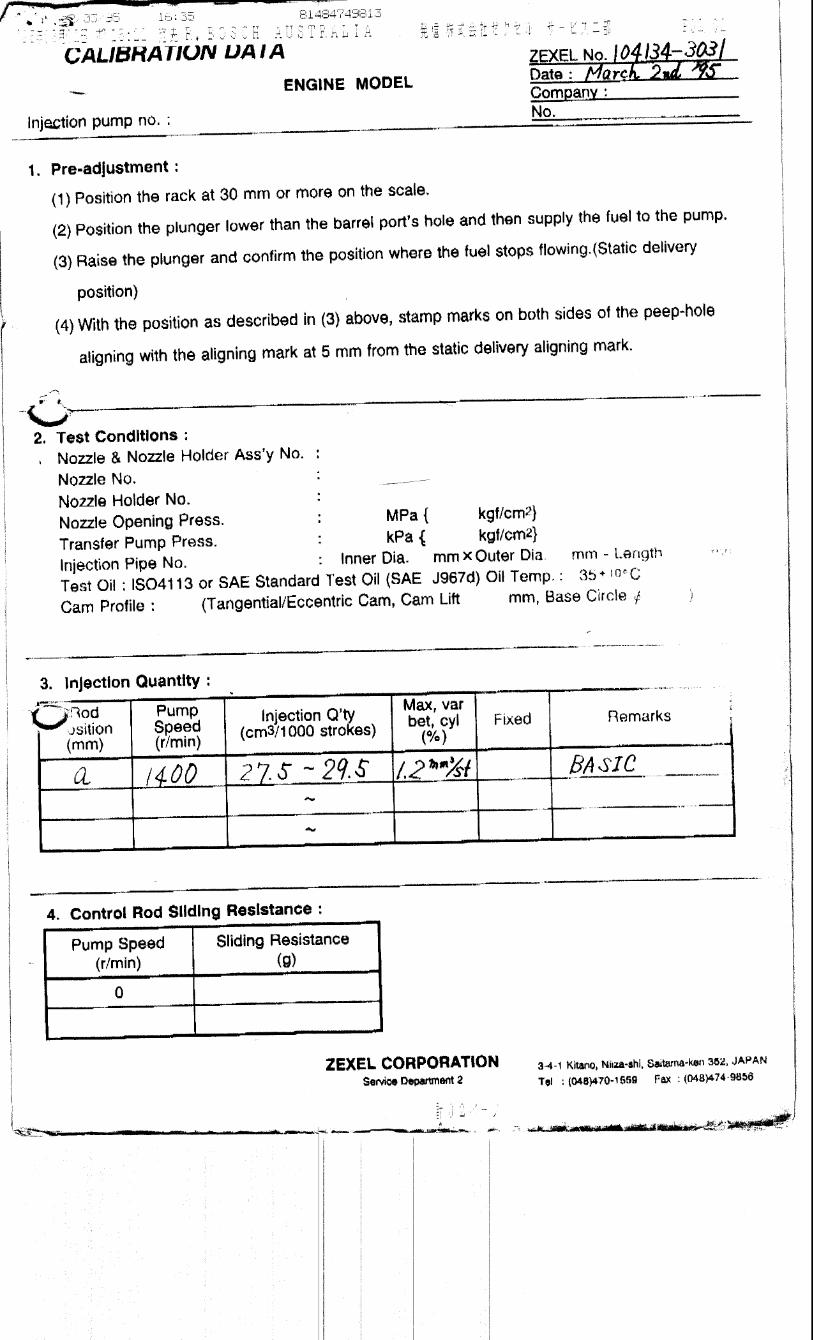


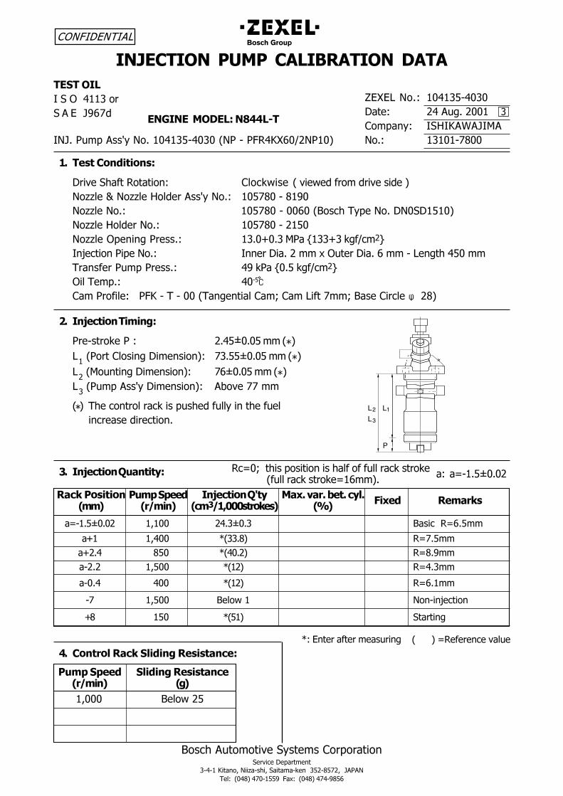
������������ ���� ������������� ���� �� ��� �
������������������������������� ����� �!�" ���#�$��
% &'��()�!*��")����+��,�-'��()�!*��"��+!�.
�� ��������� ������
����������������������������������
/0102���3' �)������)�)
���������������� !!�"��� ' ����43� ))�
������' 5�65��7�#58�
5�#3�$������9����3��)������)�)�(�$���$,:��1.); �$�)* ��3' ���)��"!))
#� ��$����%��$�
���� ����<�:�����' �&���=�� �(��� = >�<���>��� ���> �*
����& �?�����& �6�&> �����9����3' �)�"!)���!�+)
����& ���3' �)�"!)���)).)�(������%�� ���3���)�����)*
����& �6�&> ����3' �)�"!)��� ��)
����& �@� ���4�$� ��3' ��3)A)3��8$��B���A���4<;� C
5�D �����$�� ���3' 5�� �����3� ��-�@� �����3�.����2 �4����)�
%����< ��$���$� ��3' �+��$��B)3���4<;� C
@�&�% �3' �)��℃���$��<�& '���$,����%���))�(%��4 ���&���E����2�<�"E���� �����& �φ !*
&� ���������'�(�
$� ����� �$�' 3��F)3)���(G*
2��($����&����4��� �����*' "�3��F)3)���(G*
2 �(8�����4��� �����*' ".F)3)���(G*
2��($������9���� �����*' �H�� �""�
(G* %� ������&������������� >�<�&&������ �<� &
���� �� �>�� ����3
!� ���)*����+�,*%�(���$$������
� '-�,-��% ,*%�(���$$������.)/'�0 .(0
��))) � &�=� �
�I��3�F)3) ���)) �3�F)3� �������:I.3�
�A� ���)) G(��3!* :I"3�
�A 3� !�) G(�)3 * :I!3+
�� 3 ���)) G(� * :I�3�
��)3� �)) G(� * :I.3�
�" ���)) � &�=�� ������D ����
A! ��) G(��* �����4
���+��$�� � '-�,-��% ���������1�� ��2��3�)��4������*�52�% ��'�)+$
.''0 �.)/'�0 .�'�/#6777�$�)+�$0 �.80
��,�����
5 � @ �������
� � 0 #+.">
:�I)E�������������������&<��<�<�&&���������� (<�&&���������� I�.*3
�'���I��3�F)3)
(������*�I: < � �� ���&� G'�0� ���< �� ������4
�
����������
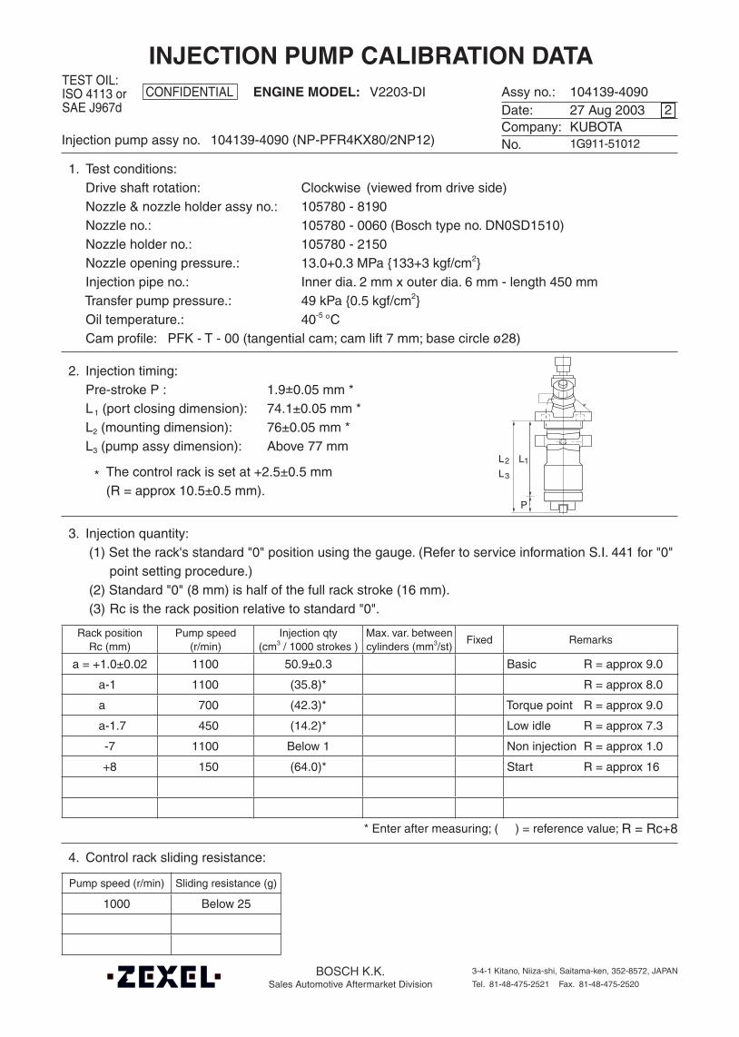
Assy no.:Date:Company:No.
CONFIDENTIALTEST OIL:ISO 4113 orSAE J967d
ENGINE MODEL:
BOSCH K.K.Sales Automotive Aftermarket Division
3-4-1 Kitano, Niiza-shi, Saitama-ken, 352-8572, JAPAN
Tel. 81-48-475-2521 Fax. 81-48-475-2520
Injection pump assy no.
INJECTION PUMP CALIBRATION DATA104139-409027 Aug 2003KUBOTA1G911-51012
V2203-DI
104139-4090 (NP-PFR4KX80/2NP12)
2
1. Test conditions: Drive shaft rotation: Clockwise (viewed from drive side) Nozzle & nozzle holder assy no.: 105780 - 8190 Nozzle no.: 105780 - 0060 (Bosch type no. DN0SD1510) Nozzle holder no.: 105780 - 2150 Nozzle opening pressure.: 13.0+0.3 MPa {133+3 kgf/cm2} Injection pipe no.: Inner dia. 2 mm x outer dia. 6 mm - length 450 mm Transfer pump pressure.: 49 kPa {0.5 kgf/cm2} Oil temperature.: 40-5 °C Cam profile: PFK - T - 00 (tangential cam; cam lift 7 mm; base circle ø28)
2. Injection timing: Pre-stroke P : 1.9±0.05 mm * L1 (port closing dimension): 74.1±0.05 mm * L2 (mounting dimension): 76±0.05 mm * L3 (pump assy dimension): Above 77 mm
* The control rack is set at +2.5±0.5 mm (R = approx 10.5±0.5 mm).
3. Injection quantity:(1) Set the rack's standard "0" position using the gauge. (Refer to service information S.I. 441 for "0"
point setting procedure.) (2) Standard "0" (8 mm) is half of the full rack stroke (16 mm). (3) Rc is the rack position relative to standard "0".
Rack positionRc (mm)
Pump speed(r/min)
Injection qty(cm3 / 1000 strokes )
Max. var. betweencylinders (mm3/st)
Fixed Remarks
a = +1.0±0.02 1100 50.9±0.3 Basic R = approx 9.0
a-1 1100 (35.8)* R = approx 8.0
a 700 (42.3)* Torque point R = approx 9.0
a-1.7 450 (14.2)* Low idle R = approx 7.3
-7 1100 Below 1 Non injection R = approx 1.0
+8 150 (64.0)* Start R = approx 16
* Enter after measuring; ( ) = reference value; R = Rc+8
4. Control rack sliding resistance:
Pump speed (r/min) Sliding resistance (g)
1000 Below 25
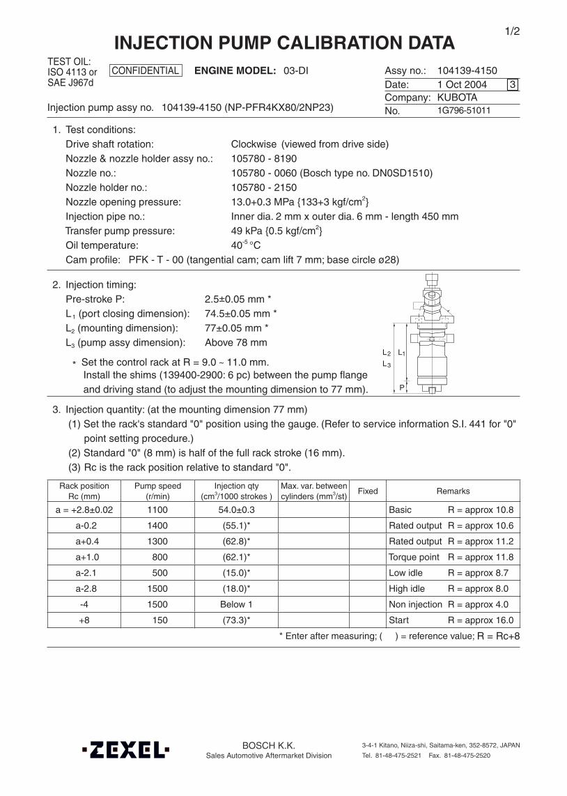
Assy no.:Date:Company:No.
CONFIDENTIALTEST OIL:ISO 4113 orSAE J967d
ENGINE MODEL:
BOSCH K.K.Sales Automotive Aftermarket Division
3-4-1 Kitano, Niiza-shi, Saitama-ken, 352-8572, JAPAN
Tel. 81-48-475-2521 Fax. 81-48-475-2520
Injection pump assy no.
INJECTION PUMP CALIBRATION DATA104139-41501 Oct 2004KUBOTA1G796-51011
03-DI
104139-4150 (NP-PFR4KX80/2NP23)
3
1. Test conditions: Drive shaft rotation: Clockwise (viewed from drive side) Nozzle & nozzle holder assy no.: 105780 - 8190 Nozzle no.: 105780 - 0060 (Bosch type no. DN0SD1510) Nozzle holder no.: 105780 - 2150 Nozzle opening pressure: 13.0+0.3 MPa {133+3 kgf/cm2} Injection pipe no.: Inner dia. 2 mm x outer dia. 6 mm - length 450 mm Transfer pump pressure: 49 kPa {0.5 kgf/cm2} Oil temperature: 40-5 °C Cam profile: PFK - T - 00 (tangential cam; cam lift 7 mm; base circle ø28)
2. Injection timing: Pre-stroke P: 2.5±0.05 mm * L1 (port closing dimension): 74.5±0.05 mm * L2 (mounting dimension): 77±0.05 mm * L3 (pump assy dimension): Above 78 mm
* Set the control rack at R = 9.0 ~ 11.0 mm.
3. Injection quantity: (at the mounting dimension 77 mm)(1) Set the rack's standard "0" position using the gauge. (Refer to service information S.I. 441 for "0"
point setting procedure.) (2) Standard "0" (8 mm) is half of the full rack stroke (16 mm). (3) Rc is the rack position relative to standard "0".
Rack positionRc (mm)
Pump speed(r/min)
Injection qty(cm3/1000 strokes )
Max. var. betweencylinders (mm3/st)
Fixed Remarks
a = +2.8±0.02 1100 54.0±0.3 Basic R = approx 10.8
a-0.2 1400 (55.1)* Rated output R = approx 10.6
a+0.4 1300 (62.8)* Rated output R = approx 11.2
a+1.0 800 (62.1)* Torque point R = approx 11.8
a-2.1 500 (15.0)* Low idle R = approx 8.7
a-2.8 1500 (18.0)* High idle R = approx 8.0
-4 1500 Below 1 Non injection R = approx 4.0
+8 150 (73.3)* Start R = approx 16.0
* Enter after measuring; ( ) = reference value; R = Rc+8
1/2
Install the shims (139400-2900: 6 pc) between the pump flangeand driving stand (to adjust the mounting dimension to 77 mm).
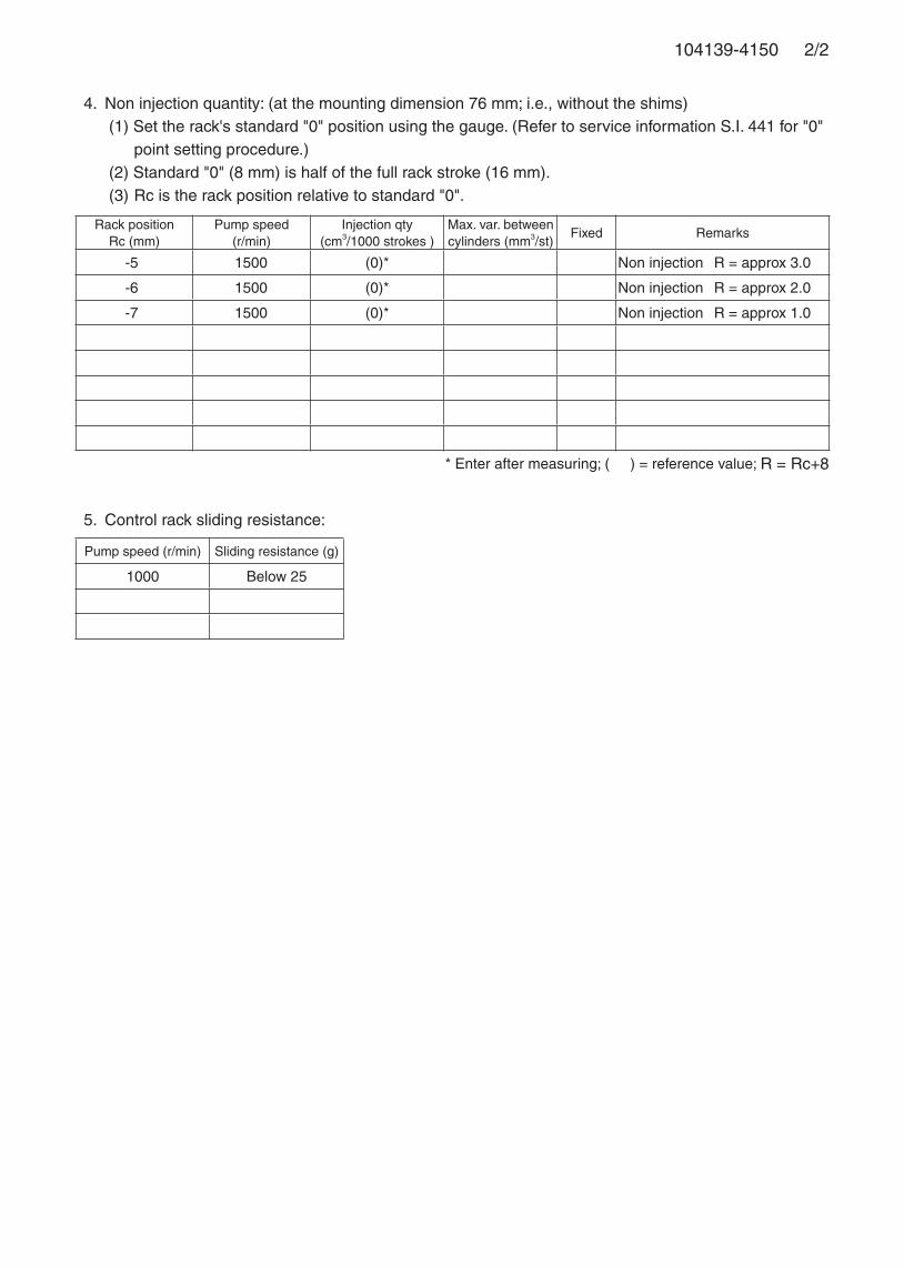
2/2104139-4150
5. Control rack sliding resistance:
Pump speed (r/min) Sliding resistance (g)
1000 Below 25
Rack positionRc (mm)
Pump speed(r/min)
Injection qty(cm3/1000 strokes )
Max. var. betweencylinders (mm3/st)
Fixed Remarks
-5 1500 (0)* Non injection R = approx 3.0
-6 1500 (0)* Non injection R = approx 2.0
-7 1500 (0)* Non injection R = approx 1.0
* Enter after measuring; ( ) = reference value; R = Rc+8
4. Non injection quantity: (at the mounting dimension 76 mm; i.e., without the shims)(1) Set the rack's standard "0" position using the gauge. (Refer to service information S.I. 441 for "0"
point setting procedure.) (2) Standard "0" (8 mm) is half of the full rack stroke (16 mm). (3) Rc is the rack position relative to standard "0".
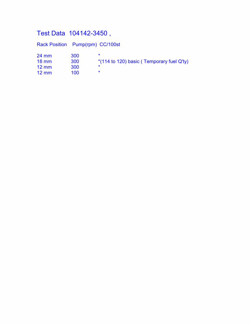
Test Data 104142-3450 ,Rack Position Pump(rpm) CC/100st
24 mm 300 *18 mm 300 *(114 to 120) basic ( Temporary fuel Q'ty)12 mm 300 *12 mm 100 *
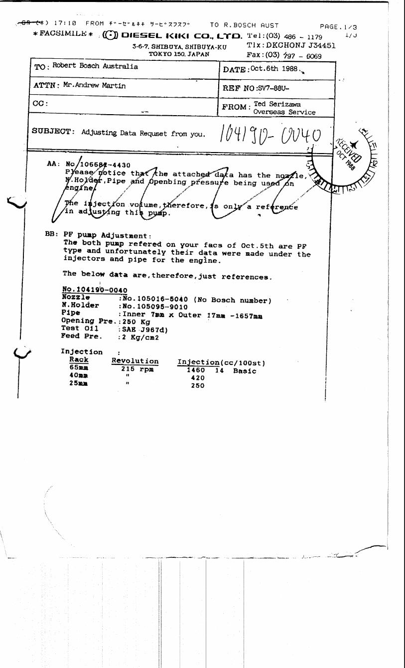
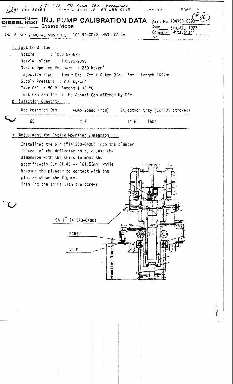
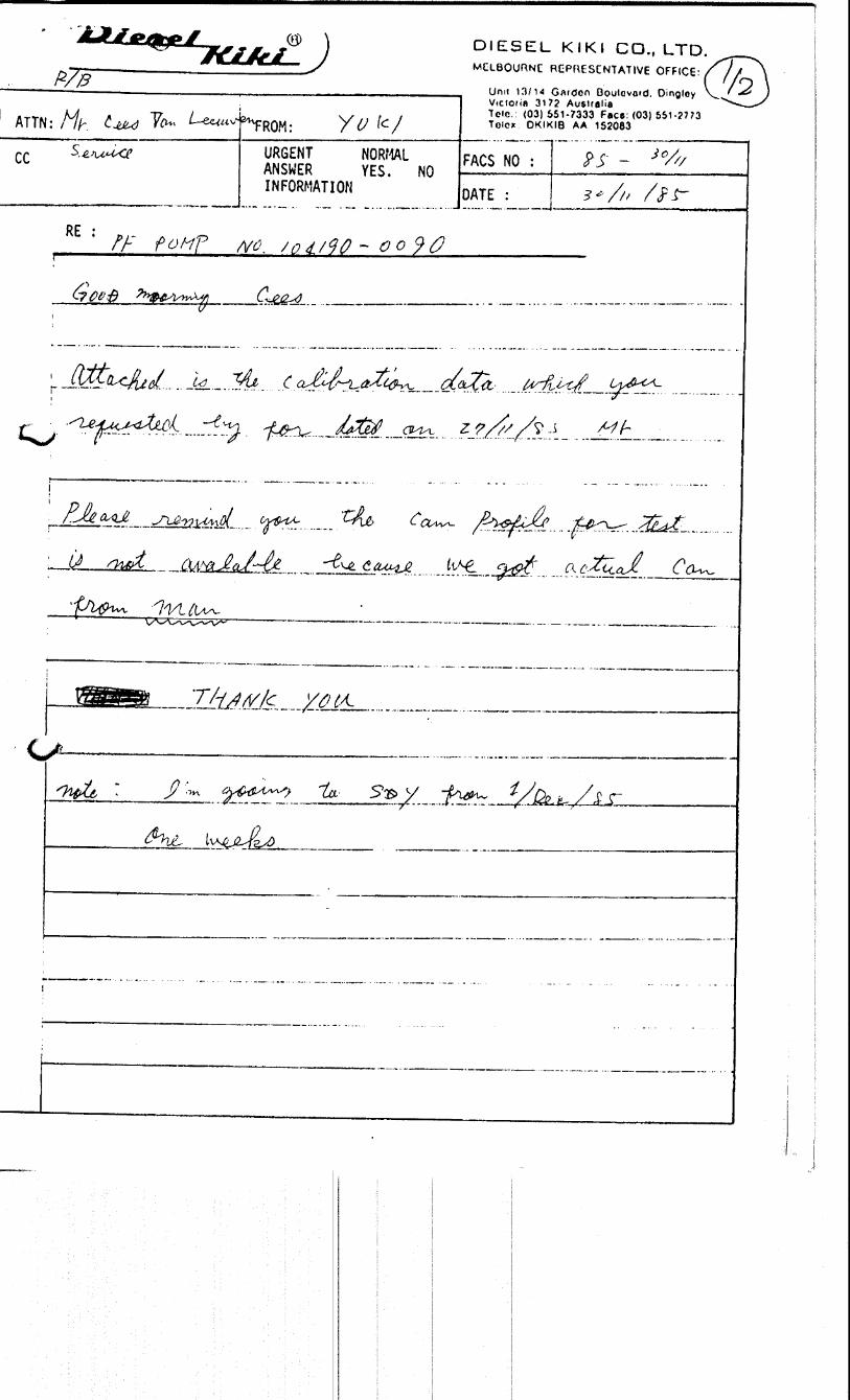
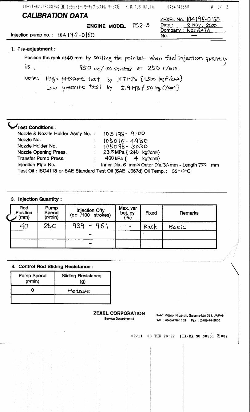
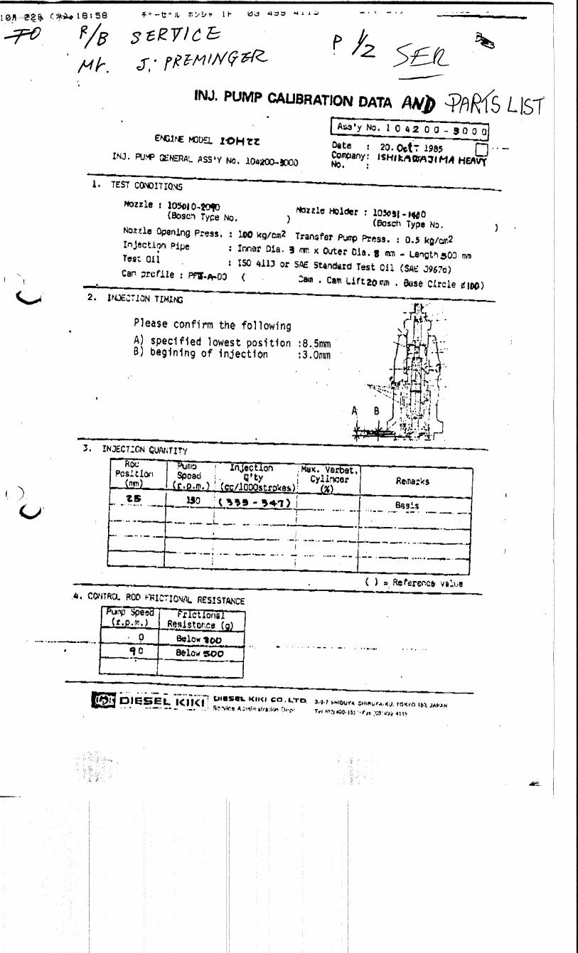
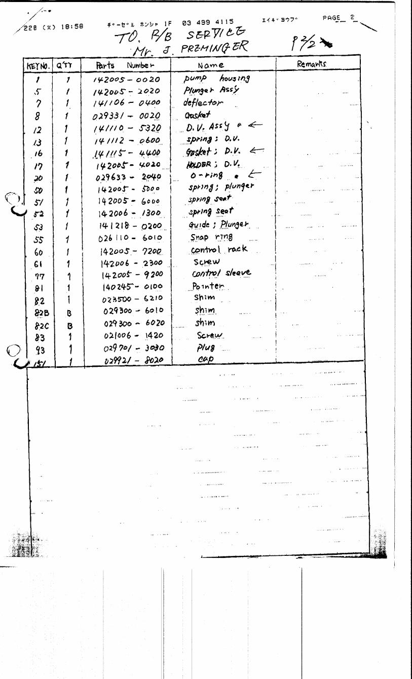
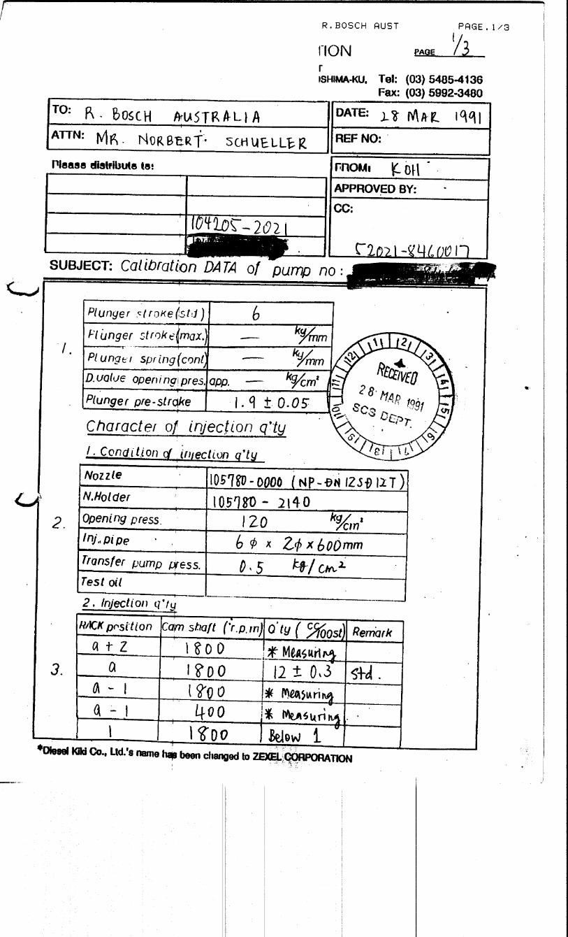
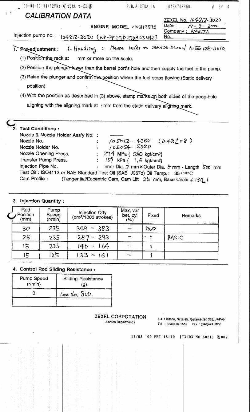
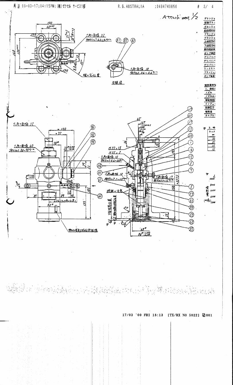
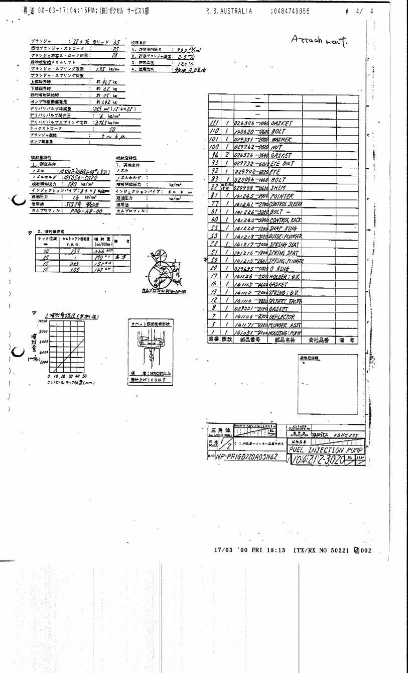
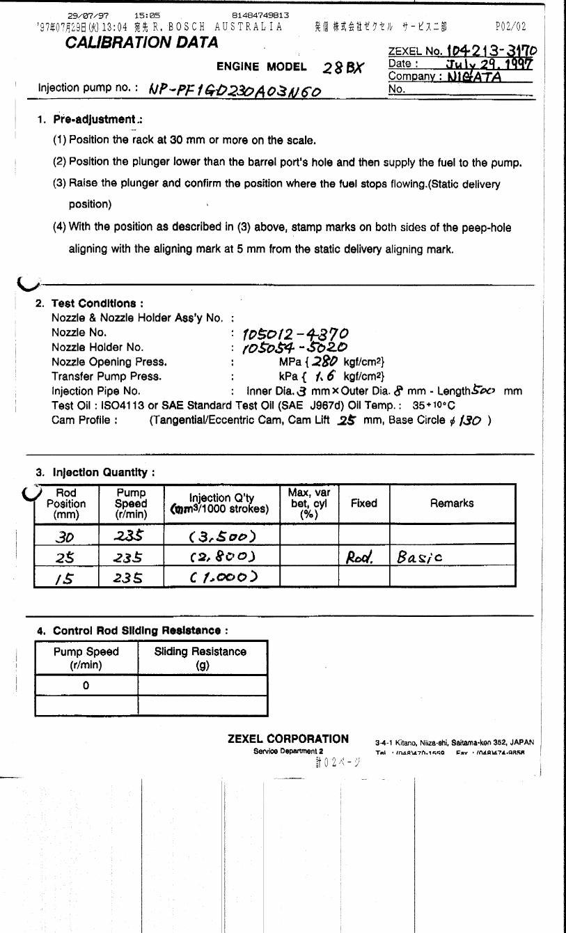
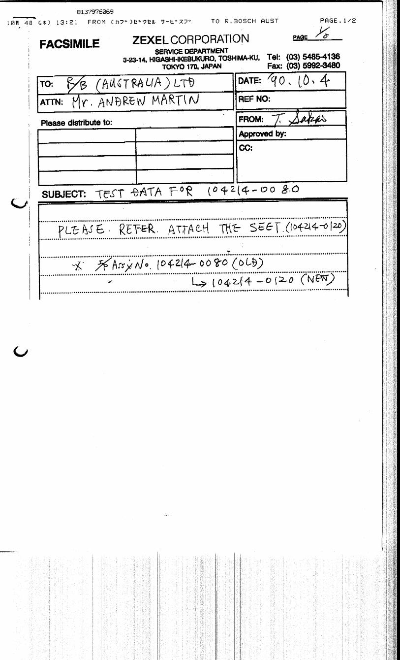

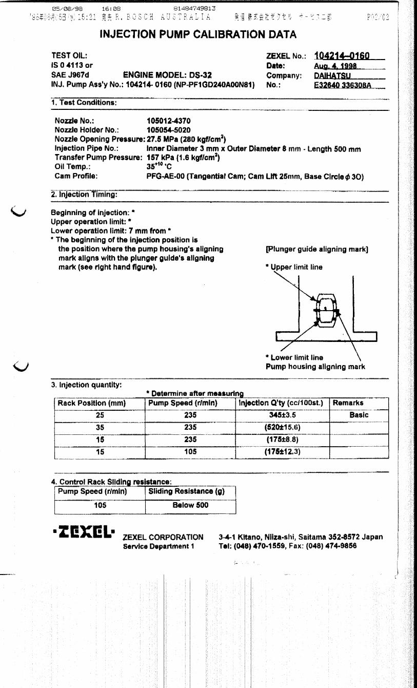
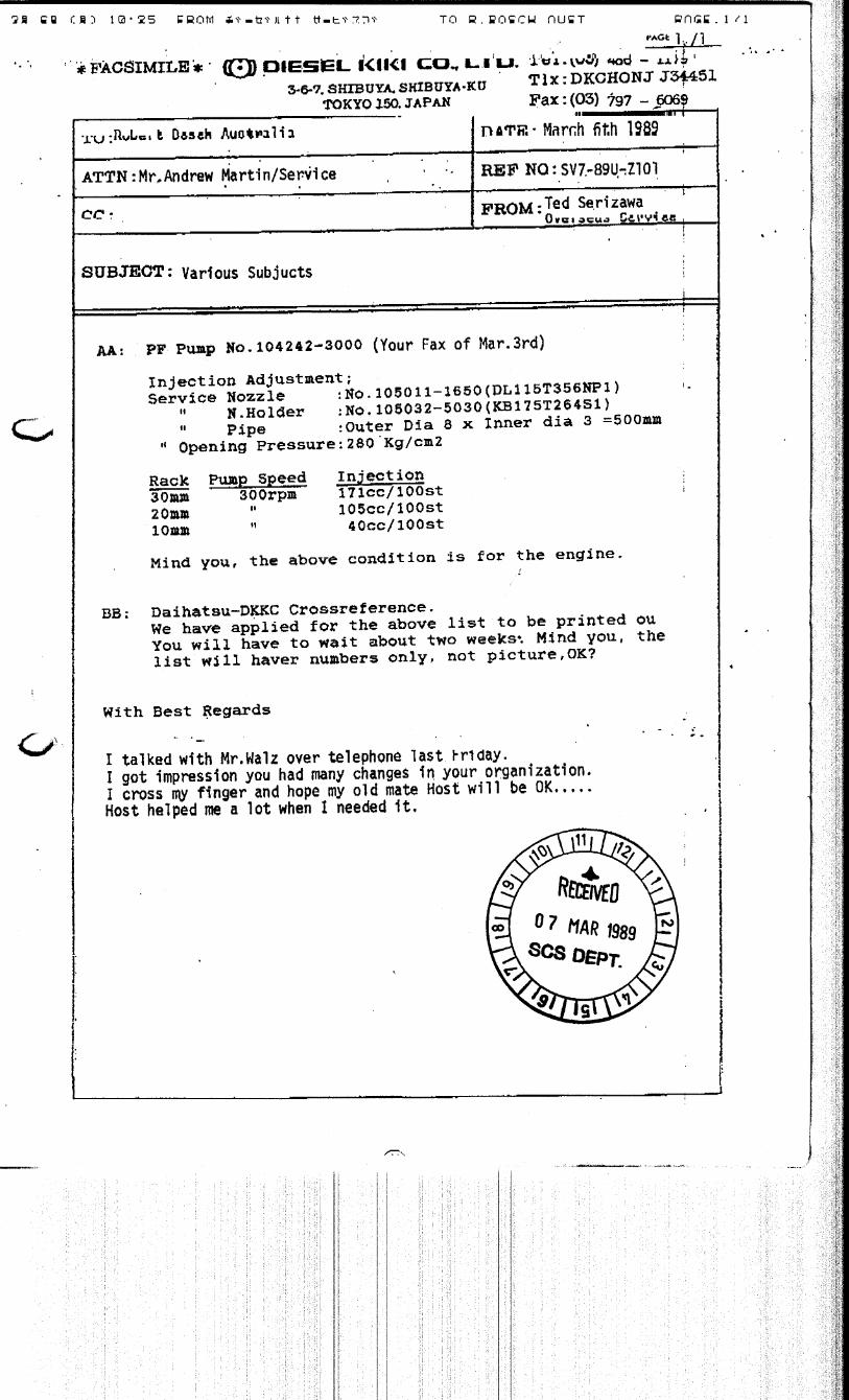
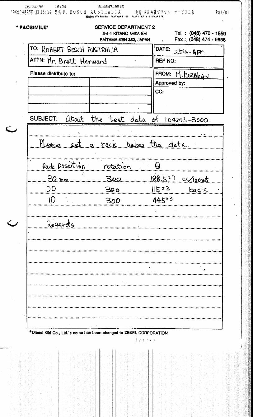


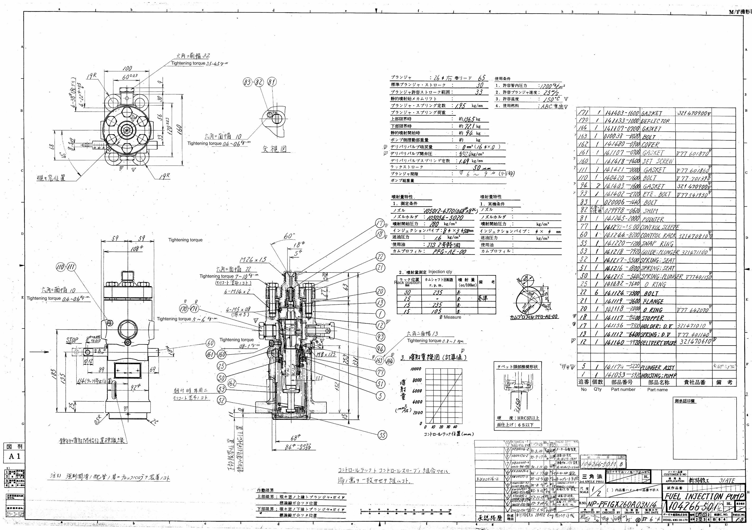
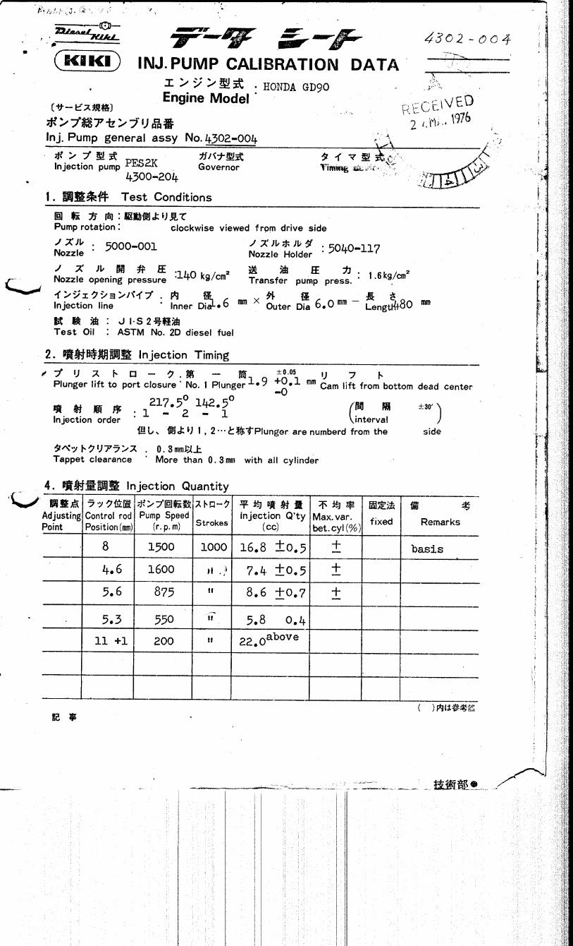
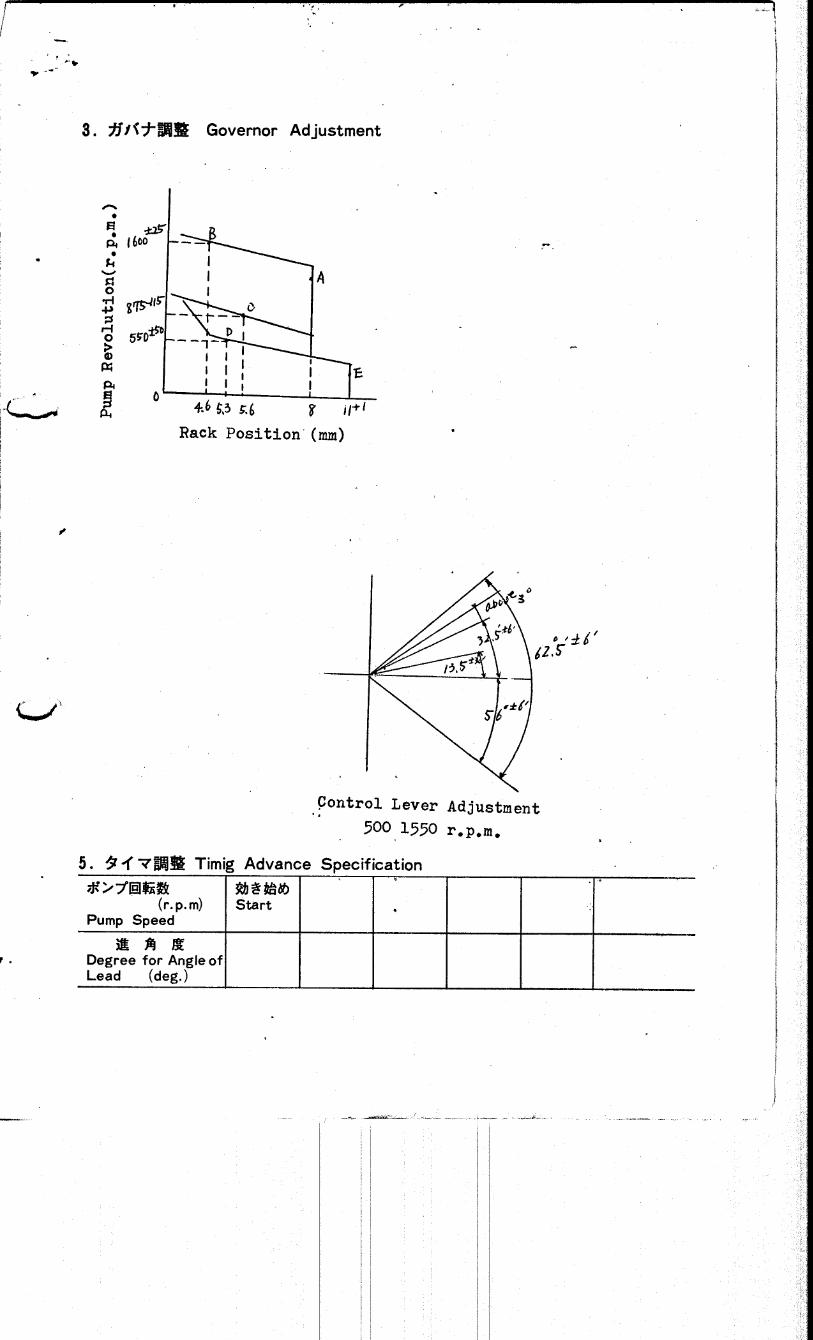


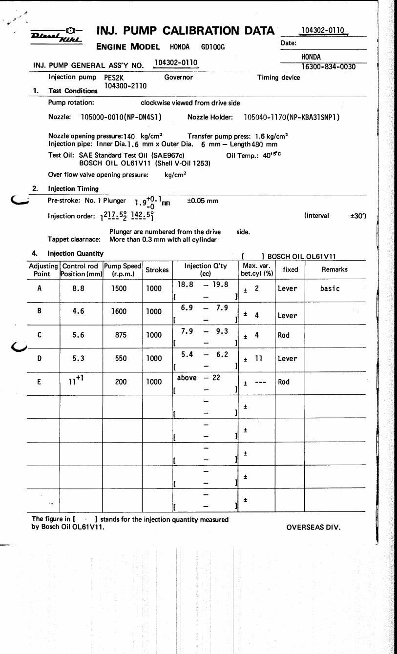
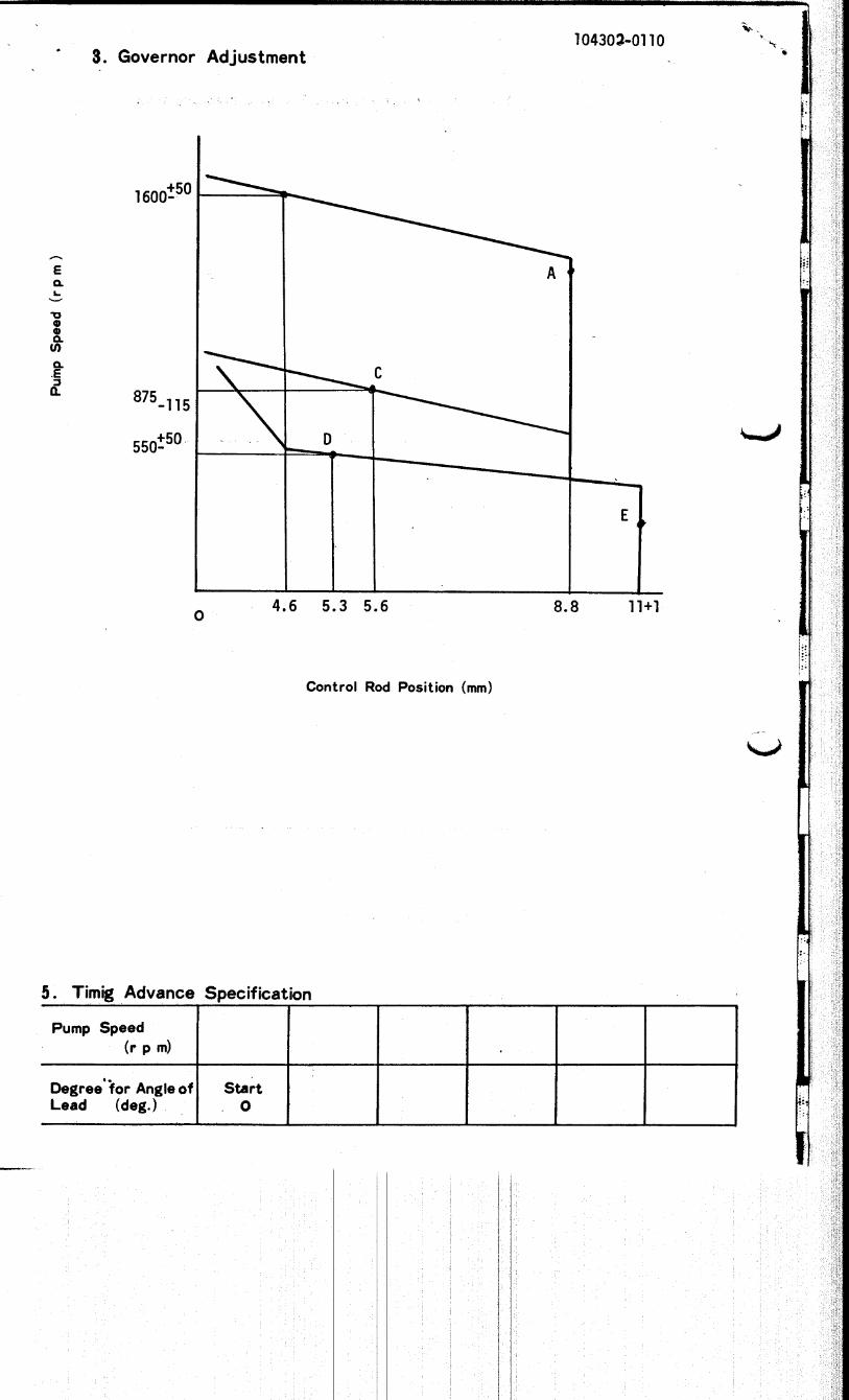

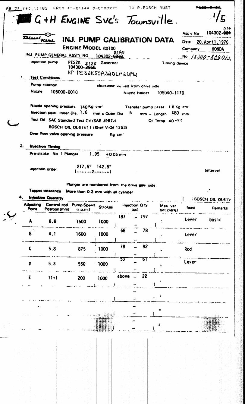


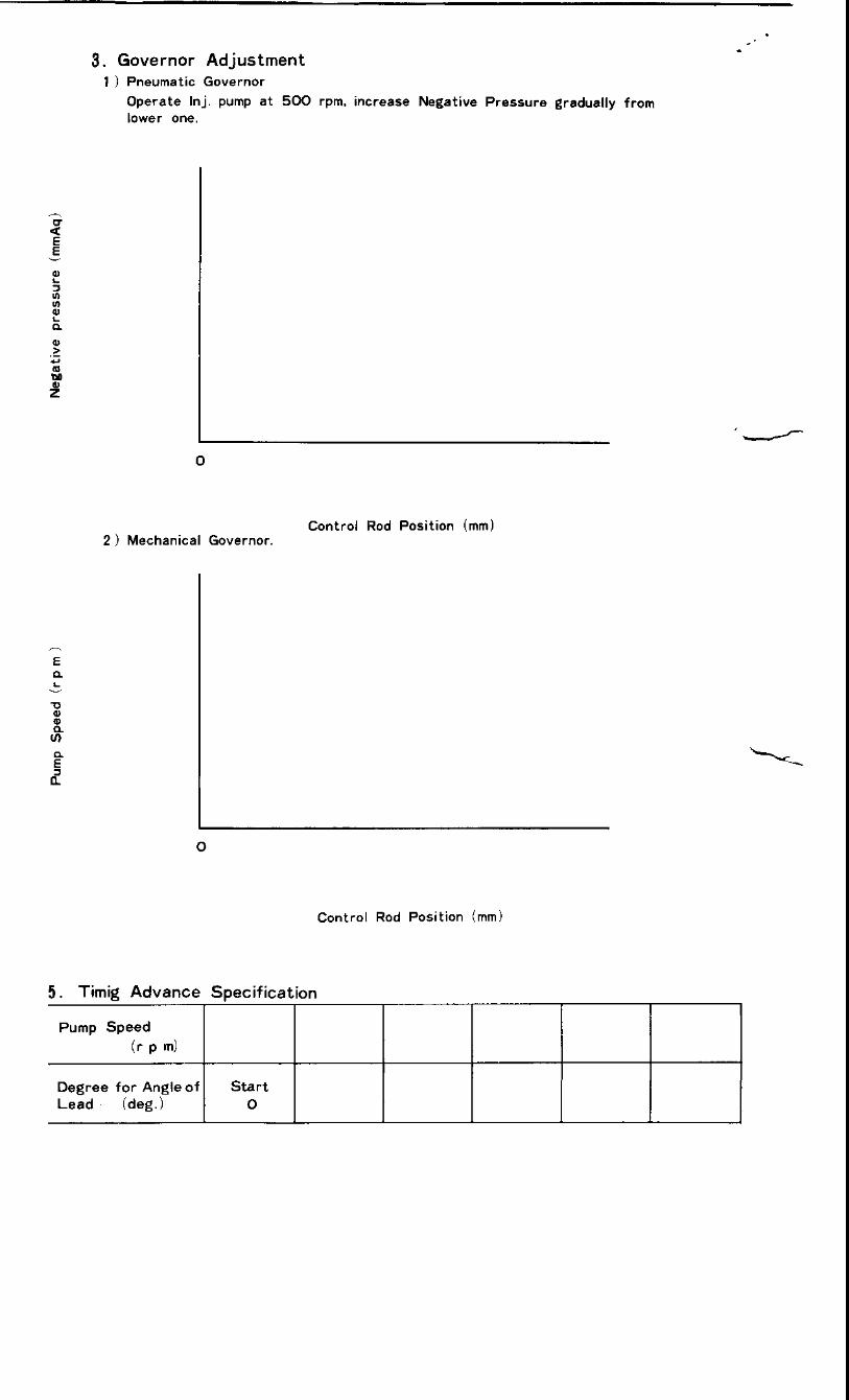
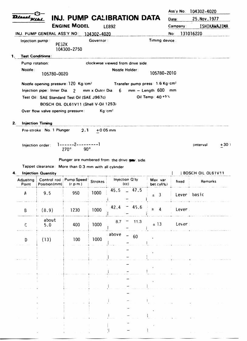
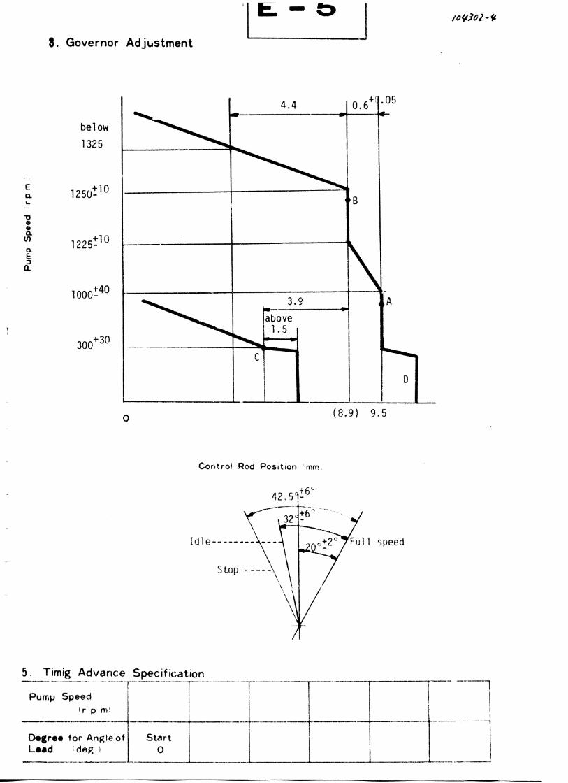
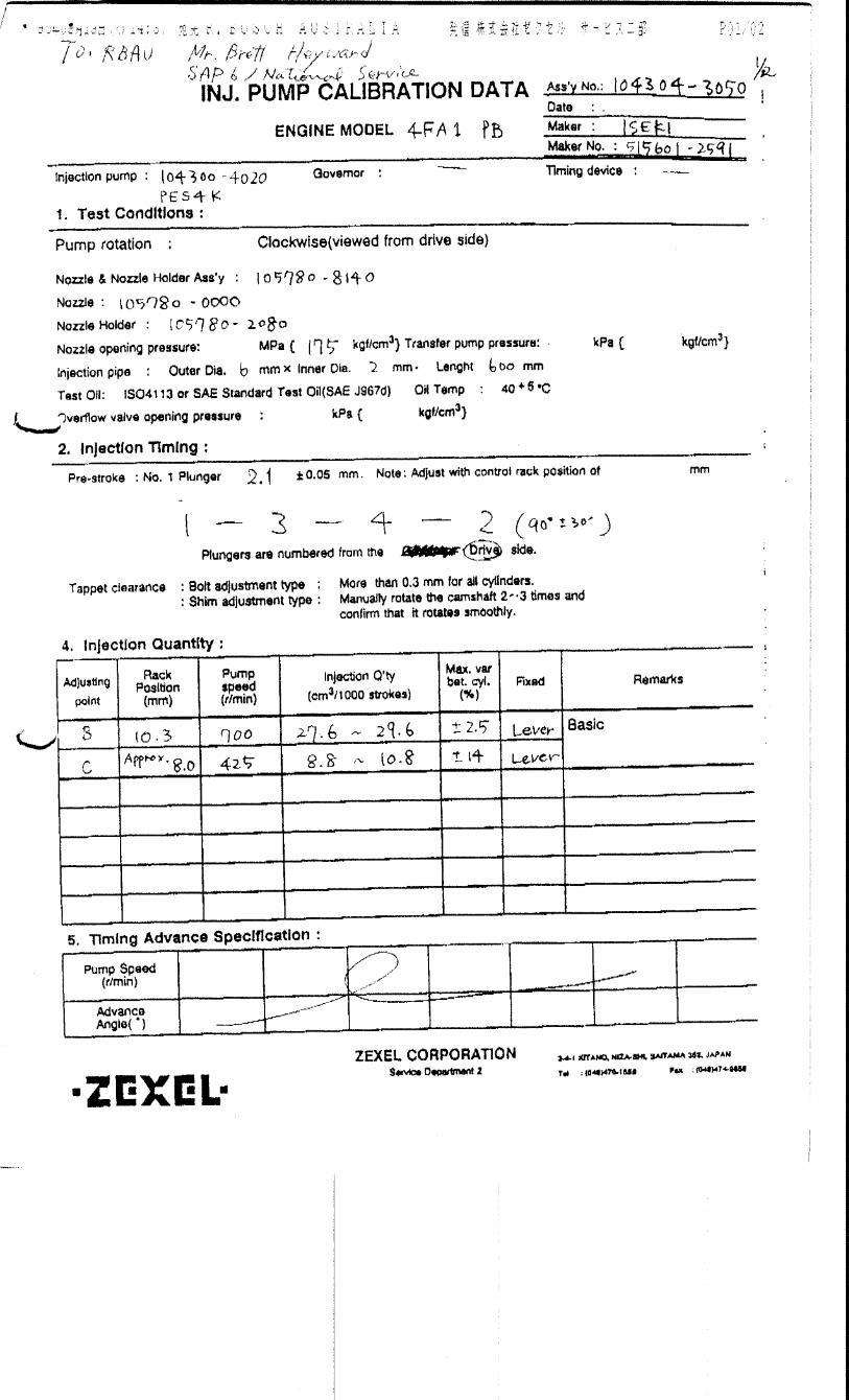
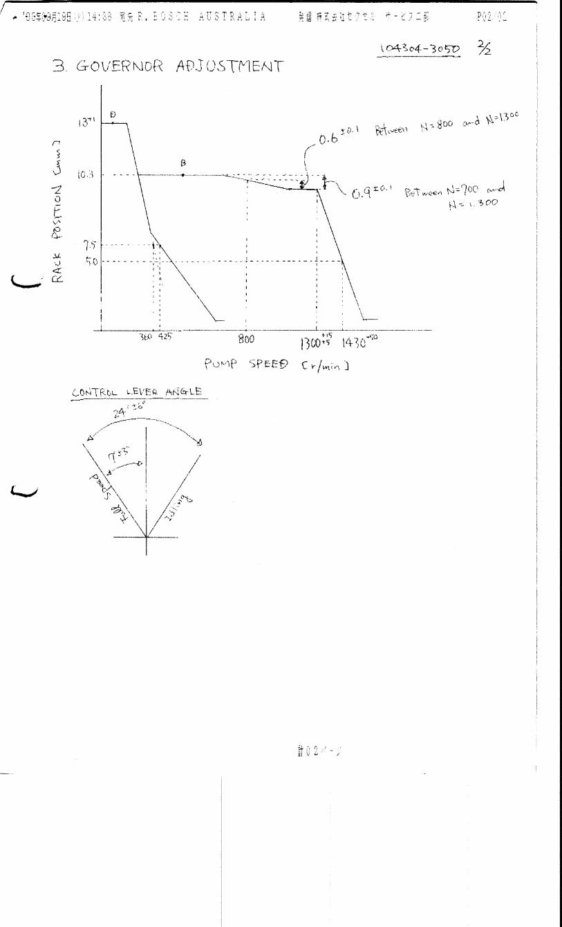
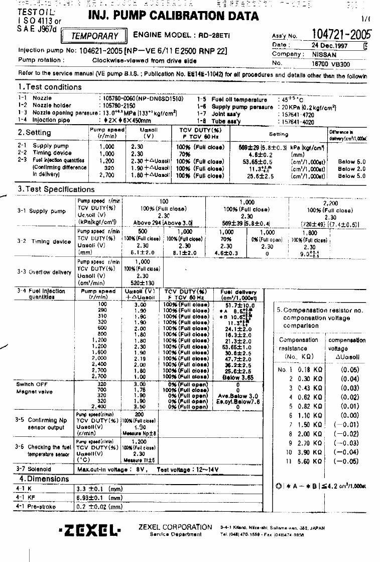
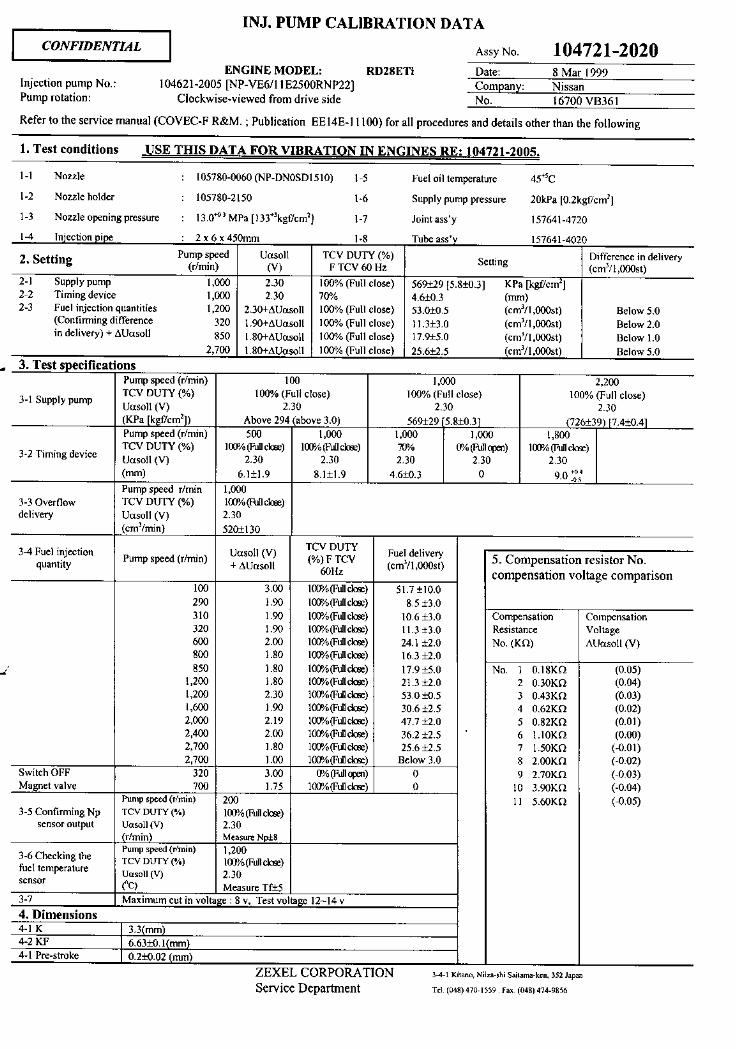
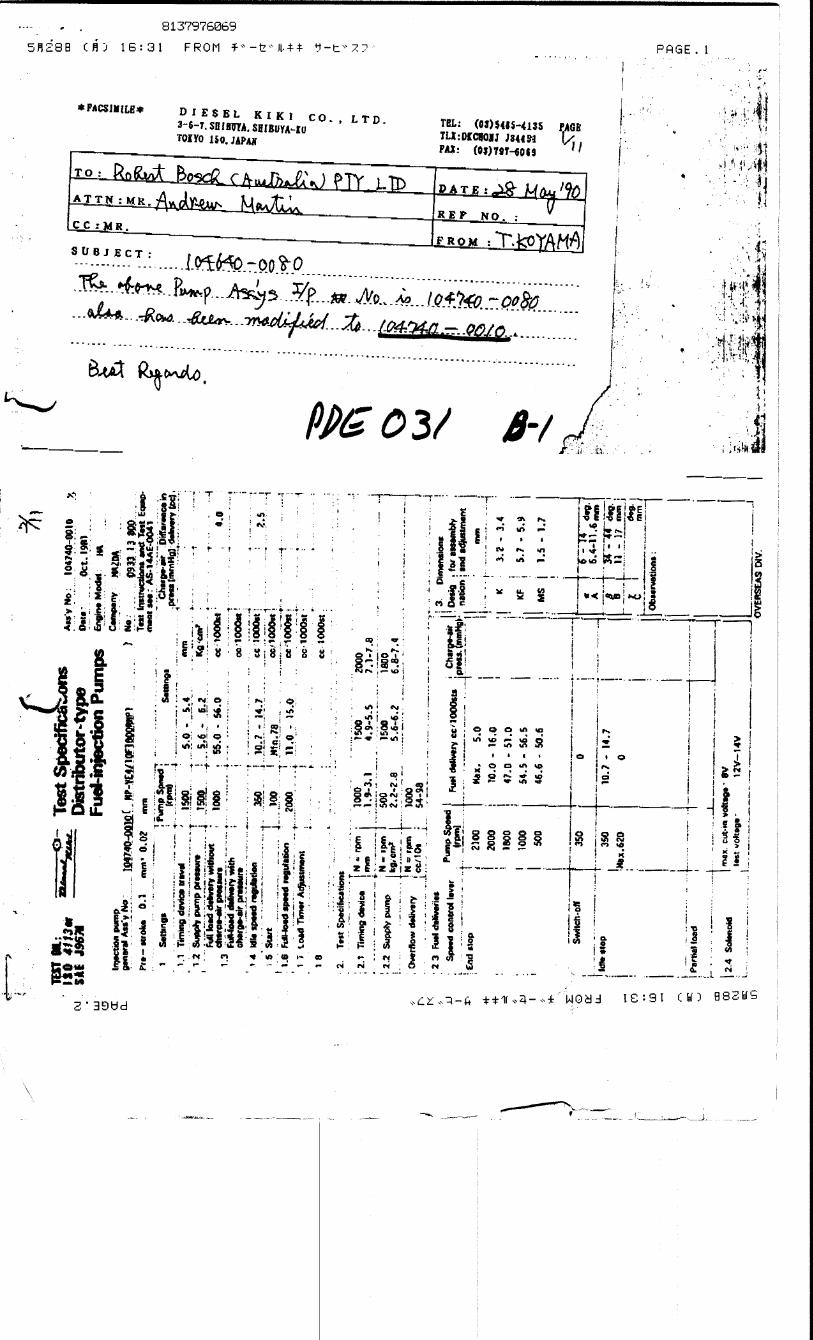
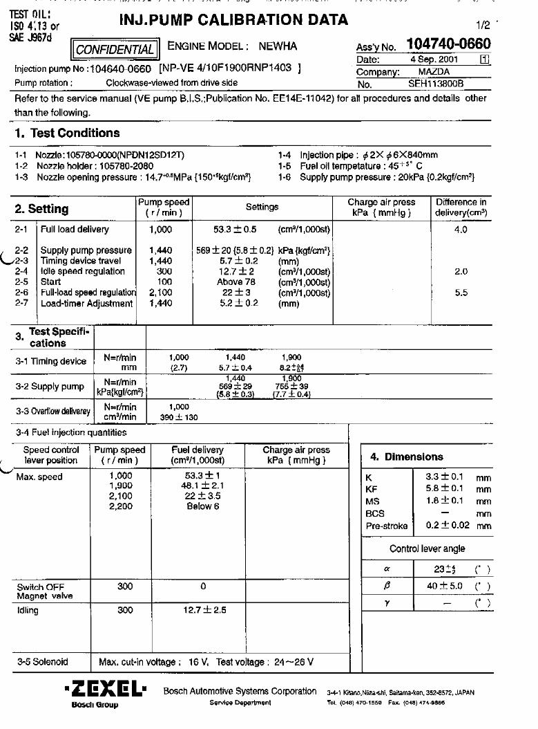
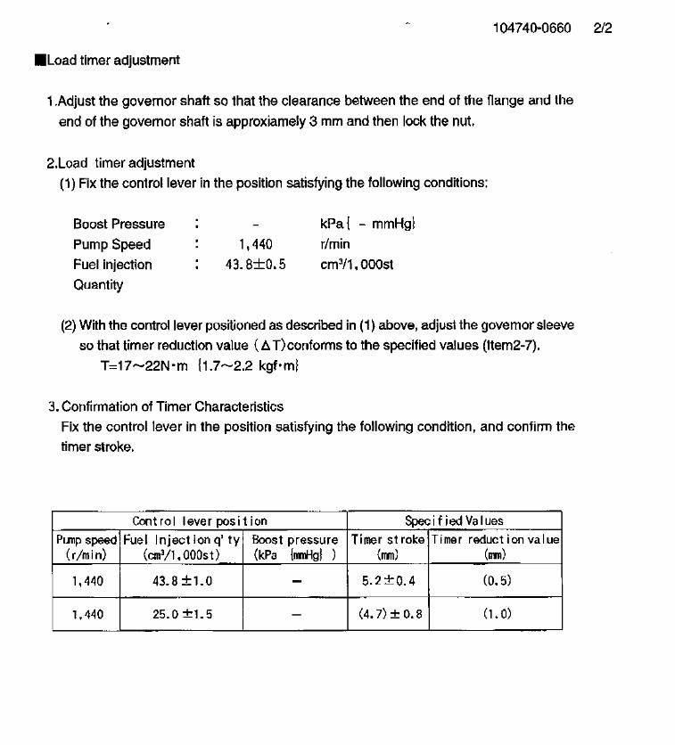
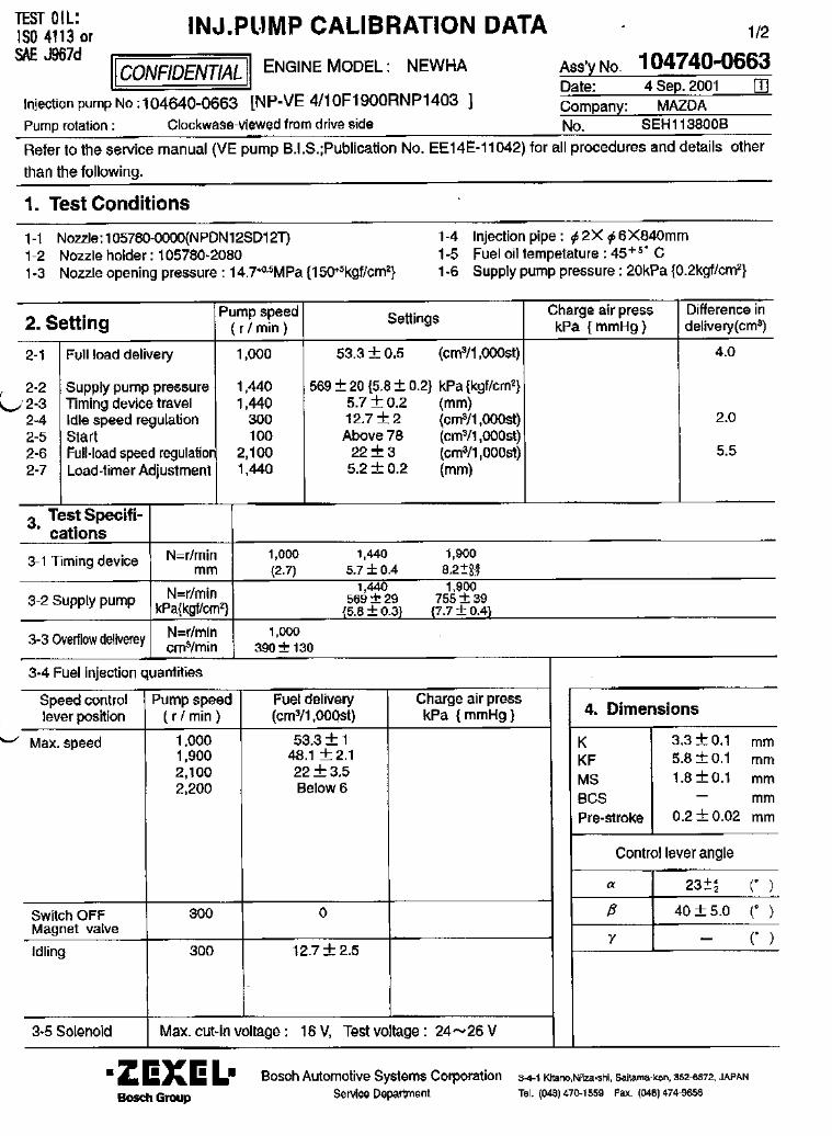


104740-0756 ZEXEL test values diesel fuel-injection equipment 14/02/02 18:32:57 Page 1
ZEXEL Ass'y No. 104740-0756Bosch Ass'y No. 9 460 612 455Bosch TypecodeEngine Type WL-NAManufactures MAZDAEdition date 20/09/00 (5)
1 Adjustment conditionsCAT Designation Unit Set value min. max. Actual values OT
Test oil ISO4113orSAEJ967d
...P Test Oil Temperature degC 45 45 50
Nozzle 105780-0060Bosch type code NP-DN0SD1510Nozzle holder 105780-2150
P Opening Pressure MPa 13 13 13.3P Opening Pressure kgf/cm2 133 133 136
Iinjection Pipe 157805-7320P Iinjection Pipe mm 2-6-450
Inside diameter - outside diameter - length (mm)Joint Assembly 157641-4720Tube Assembly 157641-4020
P Transfer pump pressure kPa 20 20 20P Transfer pump pressure kgf/cm2 0.2 0.2 0.2
Direction of rotation (viewed from drive side) LLeft
2 Adjustment specification2.1 Full load deliveryCAT Designation Unit Set value min. max. Actual values OT
P Pump speed r/min 1000 1000 1000S Average injection quantity mm3/st. 47.7 47.2 48.2S Differnce in delivery mm3/st. 4 4P Basic *P Oil temperature degC 50 48 52
CAT Designation Unit Set value min. max. Actual values OTP Pump speed r/min 500 500 500C Average injection quantity mm3/st. 46 43 49
AboutP Oil temperature degC 48 46 50
CAT Designation Unit Set value min. max. Actual values OTP Pump speed r/min 1000 1000 1000C Average injection quantity mm3/st. 47.7 46.7 48.7C Differnce in delivery mm3/st. 4.5 4.5P Basic *P Oil temperature degC 50 48 52
CAT Designation Unit Set value min. max. Actual values OTP Pump speed r/min 2000 2000 2000C Average injection quantity mm3/st. 44.4 41.9 46.9
AboutP Oil temperature degC 50 48 52
2.2 GoverningCAT Designation Unit Set value min. max. Actual values OT
P Pump speed r/min 2450 2450 2450S Average injection quantity mm3/st. 15.7 12.7 18.7S Differnce in delivery mm3/st. 5 5P Basic *P Oil temperature degC 55 52 58
CAT Designation Unit Set value min. max. Actual values OTP Pump speed r/min 2700 2700 2700C Average injection quantity mm3/st. 5 5P Oil temperature degC 55 52 58
CAT Designation Unit Set value min. max. Actual values OTP Pump speed r/min 2450 2450 2450C Average injection quantity mm3/st. 15.7 5.7 25.7C Differnce in delivery mm3/st. 5.5 5.5P Basic *P Oil temperature degC 55 52 58
2.3 IdleCAT Designation Unit Set value min. max. Actual values OT
P Pump speed r/min 360 360 360
S = Setting value, C = Check value)OT = Outside Tolerance (X is set)
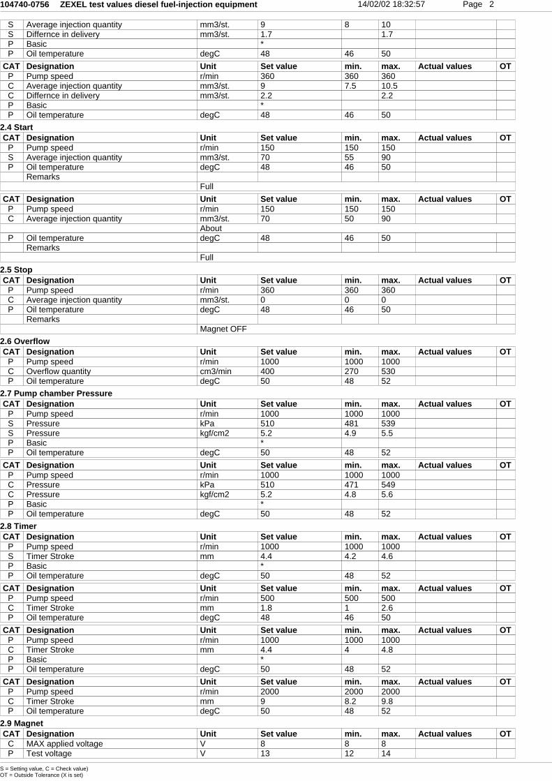
104740-0756 ZEXEL test values diesel fuel-injection equipment 14/02/02 18:32:57 Page 2
S Average injection quantity mm3/st. 9 8 10S Differnce in delivery mm3/st. 1.7 1.7P Basic *P Oil temperature degC 48 46 50
CAT Designation Unit Set value min. max. Actual values OTP Pump speed r/min 360 360 360C Average injection quantity mm3/st. 9 7.5 10.5C Differnce in delivery mm3/st. 2.2 2.2P Basic *P Oil temperature degC 48 46 50
2.4 StartCAT Designation Unit Set value min. max. Actual values OT
P Pump speed r/min 150 150 150S Average injection quantity mm3/st. 70 55 90P Oil temperature degC 48 46 50
RemarksFull
CAT Designation Unit Set value min. max. Actual values OTP Pump speed r/min 150 150 150C Average injection quantity mm3/st. 70 50 90
AboutP Oil temperature degC 48 46 50
RemarksFull
2.5 StopCAT Designation Unit Set value min. max. Actual values OT
P Pump speed r/min 360 360 360C Average injection quantity mm3/st. 0 0 0P Oil temperature degC 48 46 50
RemarksMagnet OFF
2.6 OverflowCAT Designation Unit Set value min. max. Actual values OT
P Pump speed r/min 1000 1000 1000C Overflow quantity cm3/min 400 270 530P Oil temperature degC 50 48 52
2.7 Pump chamber PressureCAT Designation Unit Set value min. max. Actual values OT
P Pump speed r/min 1000 1000 1000S Pressure kPa 510 481 539S Pressure kgf/cm2 5.2 4.9 5.5P Basic *P Oil temperature degC 50 48 52
CAT Designation Unit Set value min. max. Actual values OTP Pump speed r/min 1000 1000 1000C Pressure kPa 510 471 549C Pressure kgf/cm2 5.2 4.8 5.6P Basic *P Oil temperature degC 50 48 52
2.8 TimerCAT Designation Unit Set value min. max. Actual values OT
P Pump speed r/min 1000 1000 1000S Timer Stroke mm 4.4 4.2 4.6P Basic *P Oil temperature degC 50 48 52
CAT Designation Unit Set value min. max. Actual values OTP Pump speed r/min 500 500 500C Timer Stroke mm 1.8 1 2.6P Oil temperature degC 48 46 50
CAT Designation Unit Set value min. max. Actual values OTP Pump speed r/min 1000 1000 1000C Timer Stroke mm 4.4 4 4.8P Basic *P Oil temperature degC 50 48 52
CAT Designation Unit Set value min. max. Actual values OTP Pump speed r/min 2000 2000 2000C Timer Stroke mm 9 8.2 9.8P Oil temperature degC 50 48 52
2.9 MagnetCAT Designation Unit Set value min. max. Actual values OT
C MAX applied voltage V 8 8 8P Test voltage V 13 12 14
S = Setting value, C = Check value)OT = Outside Tolerance (X is set)
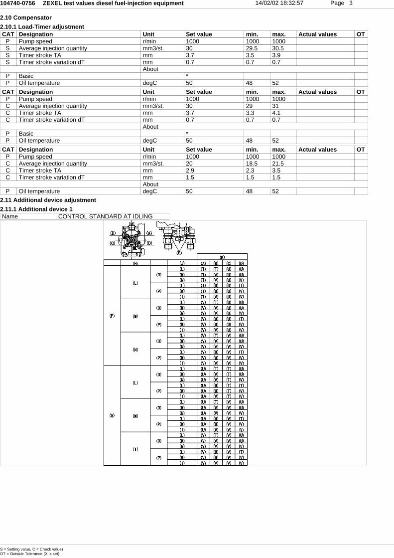
104740-0756 ZEXEL test values diesel fuel-injection equipment 14/02/02 18:32:57 Page 3
2.10 Compensator2.10.1 Load-Timer adjustmentCAT Designation Unit Set value min. max. Actual values OT
P Pump speed r/min 1000 1000 1000S Average injection quantity mm3/st. 30 29.5 30.5S Timer stroke TA mm 3.7 3.5 3.9S Timer stroke variation dT mm 0.7 0.7 0.7
AboutP Basic *P Oil temperature degC 50 48 52
CAT Designation Unit Set value min. max. Actual values OTP Pump speed r/min 1000 1000 1000C Average injection quantity mm3/st. 30 29 31C Timer stroke TA mm 3.7 3.3 4.1C Timer stroke variation dT mm 0.7 0.7 0.7
AboutP Basic *P Oil temperature degC 50 48 52
CAT Designation Unit Set value min. max. Actual values OTP Pump speed r/min 1000 1000 1000C Average injection quantity mm3/st. 20 18.5 21.5C Timer stroke TA mm 2.9 2.3 3.5C Timer stroke variation dT mm 1.5 1.5 1.5
AboutP Oil temperature degC 50 48 52
2.11 Additional device adjustment2.11.1 Additional device 1Name CONTROL STANDARD AT IDLING
S = Setting value, C = Check value)OT = Outside Tolerance (X is set)
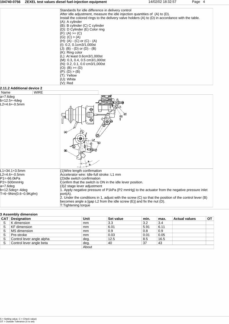
104740-0756 ZEXEL test values diesel fuel-injection equipment 14/02/02 18:32:57 Page 4
Standards for idle difference in delivery controlAfter idle adjustment, measure the idle injection quantities of (A) to (D).Install the colored rings to the delivery valve holders (A) to (D) in accordance with the table.(A): A cylinder(B): B cylinder (C) C cylinder(D): D Cylinder (E) Color ring(F): (A) >= (C)(G): (C) > (A)(H): (A) - (C) or (C) - (A)(I): 0.2, 0.1cm3/1,000st(J): (B) - (D) or (D) - (B)(K): Ring color(L): At least 0.6cm3/1,000st(M): 0.3, 0.4, 0.5 cm3/1,000st(N): 0.2, 0.1, 0.0 cm3/1,000st(O): (B) >= (D)(P): (D) > (B)(T): Yellow(U): White(V): Red
2.11.2 Additional device 2Name WIRE
a=7.6degb=12.5+-4degL2=4.6+-0.5mm
L1=34.1+3.5mmL2=4.6+-0.5mmP1=-66.0kPaP2=-500mmHga=7.6degb=12.5deg+-4degT=6~9Nm(0.6~0.9Kgfm)
(1)Wire length confirmationAccelerator wire: Idle-full stroke: L1 mm(2)Idle switch confirmationConfirm that the switch is ON in the idle lever position.(3)2 stage lever adjustment1. Apply negative pressure of P1kPa {P2 mmHg} to the actuator from the negative pressure inletport(A).2. Under the conditions in 1, adjust with the screw (C) so that the position of the control lever (B)becomes angle a [gap L2 from the idle screw (E)] and fix the nut (D).T:Tightening torque
3 Assembly dimensionCAT Designation Unit Set value min. max. Actual values OT
S K dimension mm 3.3 3.2 3.4S KF dimension mm 6.01 5.91 6.11S MS dimension mm 0.9 0.8 0.9S Pre-stroke mm 0.03 0.01 0.05S Control lever angle alpha deg. 12.5 8.5 16.5S Control lever angle beta deg. 40 37 43
About
S = Setting value, C = Check value)OT = Outside Tolerance (X is set)


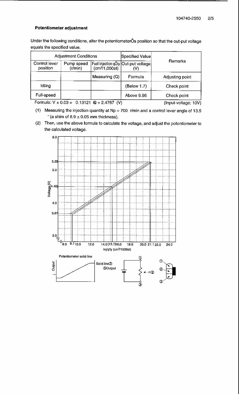
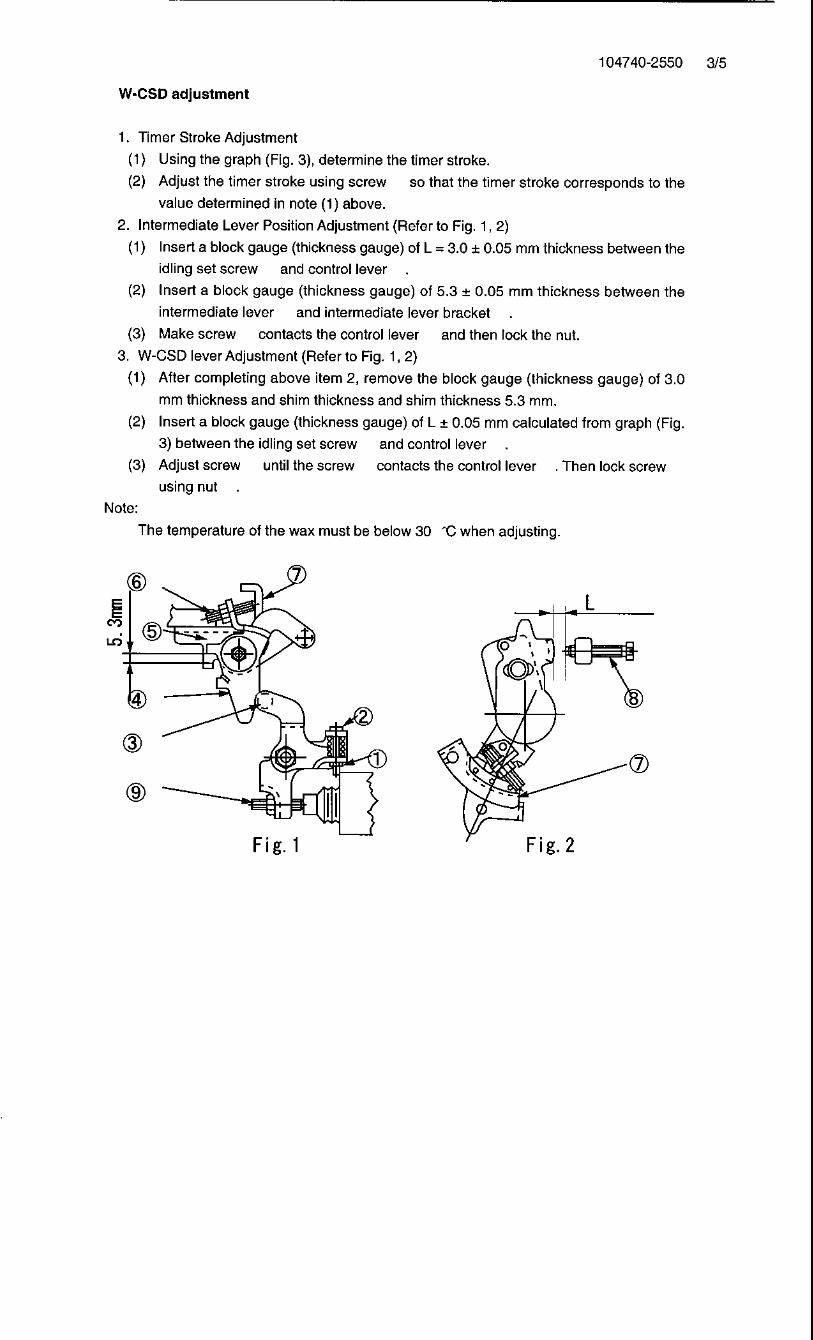
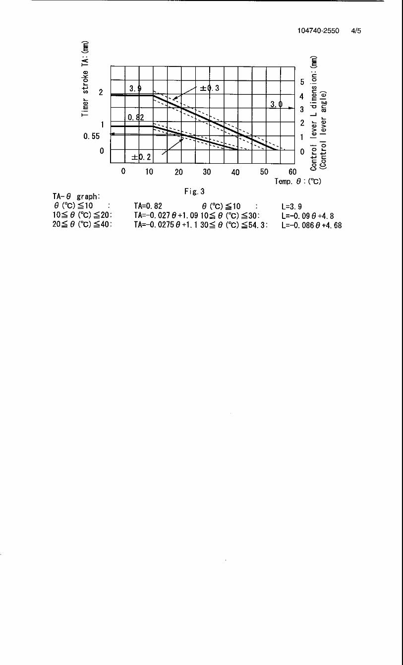
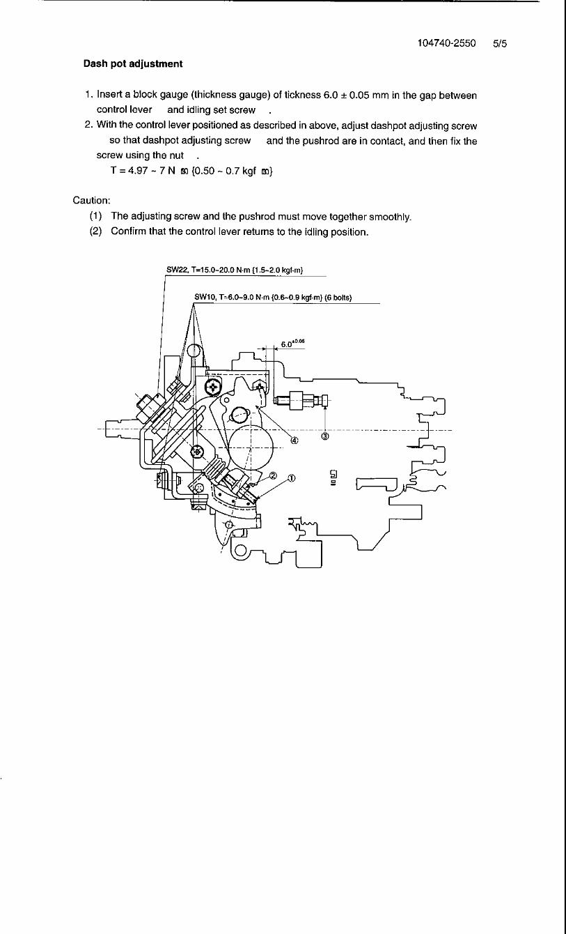
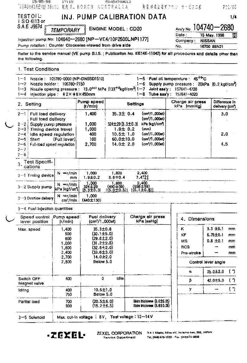
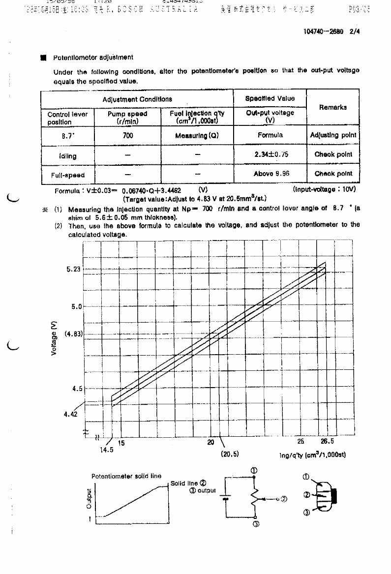
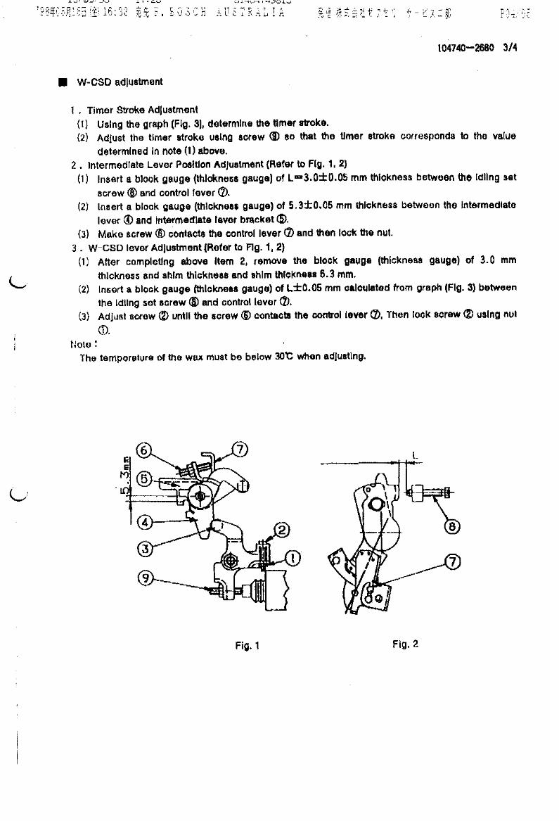
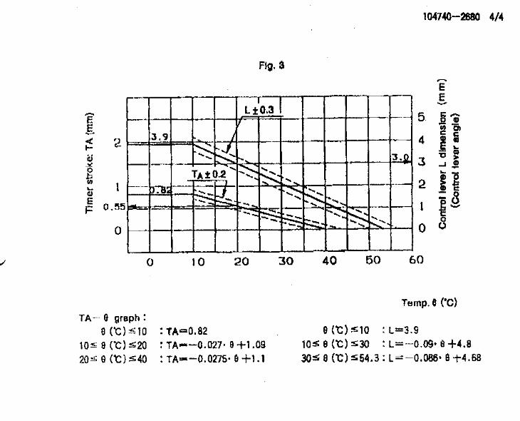


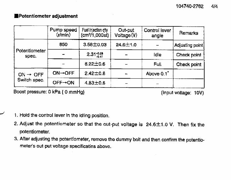

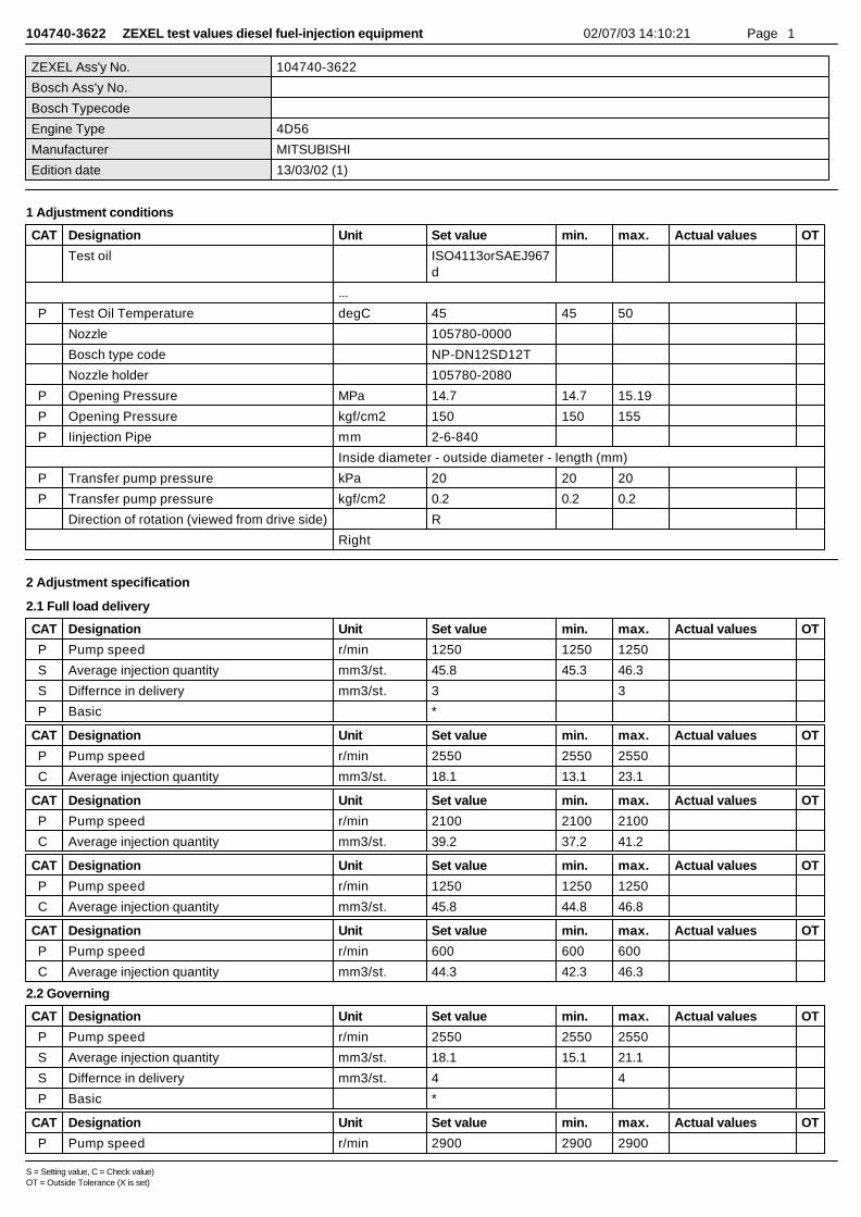
104740-3622 ZEXEL test values diesel fuel-injection equipment 02/07/03 14:10:21 Page 1
ZEXEL Ass'y No. 104740-3622
Bosch Ass'y No.
Bosch Typecode
Engine Type 4D56
Manufacturer MITSUBISHI
Edition date 13/03/02 (1)
1 Adjustment conditions
CAT Designation Unit Set value min. max. Actual values OT
Test oil ISO4113orSAEJ967d
...
P Test Oil Temperature degC 45 45 50
Nozzle 105780-0000
Bosch type code NP-DN12SD12T
Nozzle holder 105780-2080
P Opening Pressure MPa 14.7 14.7 15.19
P Opening Pressure kgf/cm2 150 150 155
P Iinjection Pipe mm 2-6-840
Inside diameter - outside diameter - length (mm)
P Transfer pump pressure kPa 20 20 20
P Transfer pump pressure kgf/cm2 0.2 0.2 0.2
Direction of rotation (viewed from drive side) R
Right
2 Adjustment specification
2.1 Full load delivery
CAT Designation Unit Set value min. max. Actual values OT
P Pump speed r/min 1250 1250 1250
S Average injection quantity mm3/st. 45.8 45.3 46.3
S Differnce in delivery mm3/st. 3 3
P Basic *
CAT Designation Unit Set value min. max. Actual values OT
P Pump speed r/min 2550 2550 2550
C Average injection quantity mm3/st. 18.1 13.1 23.1
CAT Designation Unit Set value min. max. Actual values OT
P Pump speed r/min 2100 2100 2100
C Average injection quantity mm3/st. 39.2 37.2 41.2
CAT Designation Unit Set value min. max. Actual values OT
P Pump speed r/min 1250 1250 1250
C Average injection quantity mm3/st. 45.8 44.8 46.8
CAT Designation Unit Set value min. max. Actual values OT
P Pump speed r/min 600 600 600
C Average injection quantity mm3/st. 44.3 42.3 46.3
2.2 Governing
CAT Designation Unit Set value min. max. Actual values OT
P Pump speed r/min 2550 2550 2550
S Average injection quantity mm3/st. 18.1 15.1 21.1
S Differnce in delivery mm3/st. 4 4
P Basic *
CAT Designation Unit Set value min. max. Actual values OT
P Pump speed r/min 2900 2900 2900
S = Setting value, C = Check value)OT = Outside Tolerance (X is set)
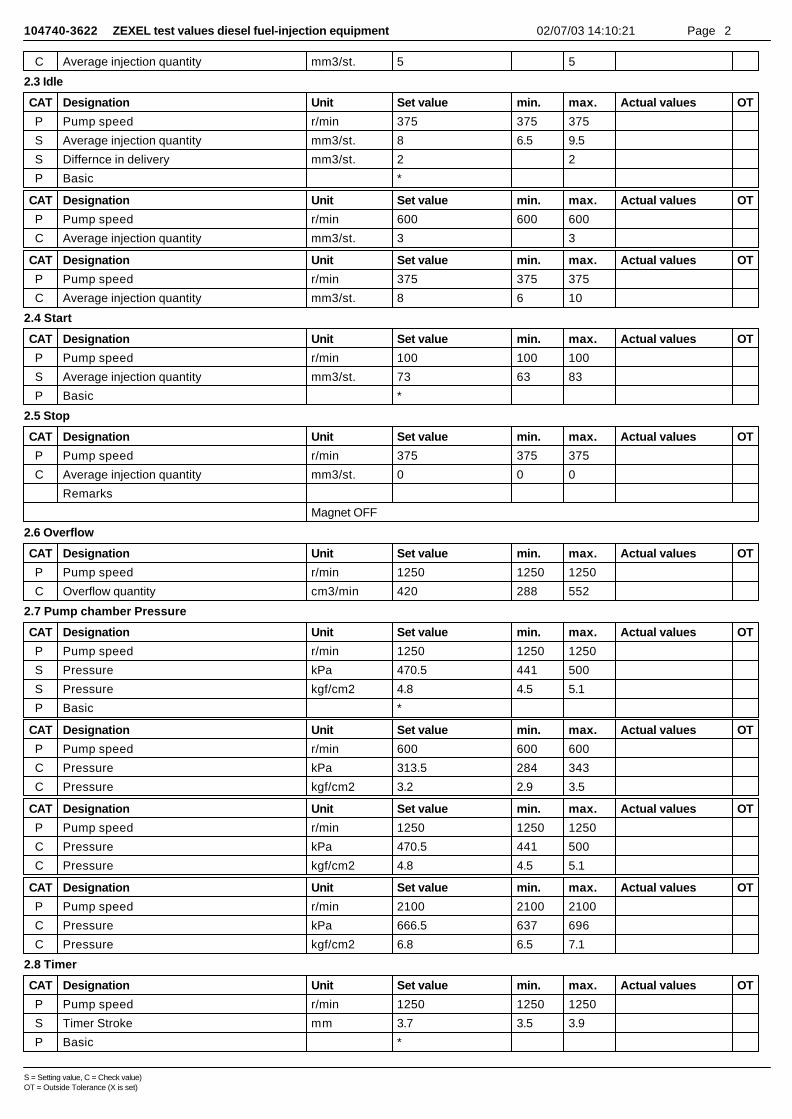
104740-3622 ZEXEL test values diesel fuel-injection equipment 02/07/03 14:10:21 Page 2
C Average injection quantity mm3/st. 5 5
2.3 Idle
CAT Designation Unit Set value min. max. Actual values OT
P Pump speed r/min 375 375 375
S Average injection quantity mm3/st. 8 6.5 9.5
S Differnce in delivery mm3/st. 2 2
P Basic *
CAT Designation Unit Set value min. max. Actual values OT
P Pump speed r/min 600 600 600
C Average injection quantity mm3/st. 3 3
CAT Designation Unit Set value min. max. Actual values OT
P Pump speed r/min 375 375 375
C Average injection quantity mm3/st. 8 6 10
2.4 Start
CAT Designation Unit Set value min. max. Actual values OT
P Pump speed r/min 100 100 100
S Average injection quantity mm3/st. 73 63 83
P Basic *
2.5 Stop
CAT Designation Unit Set value min. max. Actual values OT
P Pump speed r/min 375 375 375
C Average injection quantity mm3/st. 0 0 0
Remarks
Magnet OFF
2.6 Overflow
CAT Designation Unit Set value min. max. Actual values OT
P Pump speed r/min 1250 1250 1250
C Overflow quantity cm3/min 420 288 552
2.7 Pump chamber Pressure
CAT Designation Unit Set value min. max. Actual values OT
P Pump speed r/min 1250 1250 1250
S Pressure kPa 470.5 441 500
S Pressure kgf/cm2 4.8 4.5 5.1
P Basic *
CAT Designation Unit Set value min. max. Actual values OT
P Pump speed r/min 600 600 600
C Pressure kPa 313.5 284 343
C Pressure kgf/cm2 3.2 2.9 3.5
CAT Designation Unit Set value min. max. Actual values OT
P Pump speed r/min 1250 1250 1250
C Pressure kPa 470.5 441 500
C Pressure kgf/cm2 4.8 4.5 5.1
CAT Designation Unit Set value min. max. Actual values OT
P Pump speed r/min 2100 2100 2100
C Pressure kPa 666.5 637 696
C Pressure kgf/cm2 6.8 6.5 7.1
2.8 Timer
CAT Designation Unit Set value min. max. Actual values OT
P Pump speed r/min 1250 1250 1250
S Timer Stroke mm 3.7 3.5 3.9
P Basic *
S = Setting value, C = Check value)OT = Outside Tolerance (X is set)

104740-3622 ZEXEL test values diesel fuel-injection equipment 02/07/03 14:10:21 Page 3
CAT Designation Unit Set value min. max. Actual values OT
P Pump speed r/min 500 500 500
C Timer Stroke mm 1.2 0.6 1.8
CAT Designation Unit Set value min. max. Actual values OT
P Pump speed r/min 750 750 750
C Timer Stroke mm 2 1.4 2.6
CAT Designation Unit Set value min. max. Actual values OT
P Pump speed r/min 1250 1250 1250
C Timer Stroke mm 3.7 3.3 4.1
CAT Designation Unit Set value min. max. Actual values OT
P Pump speed r/min 2100 2100 2100
C Timer Stroke mm 7.2 6.6 7.8
2.9 Magnet
CAT Designation Unit Set value min. max. Actual values OT
C MAX applied voltage V 8 8 8
P Test voltage V 13 12 14
2.10 Compensator
2.10.1 Load-Timer adjustment
CAT Designation Unit Set value min. max. Actual values OT
P Pump speed r/min 1250 1250 1250
S Average injection quantity mm3/st. 35.7 35.2 36.2
S Timer stroke variation dT mm 0.6 0.4 0.8
P Basic *
CAT Designation Unit Set value min. max. Actual values OT
P Pump speed r/min 1250 1250 1250
C Average injection quantity mm3/st. 35.7 34.7 36.7
C Timer stroke TA mm 3.1 3.1 3.1
About
C Timer stroke variation dT mm 0.6 0.2 1
CAT Designation Unit Set value min. max. Actual values OT
P Pump speed r/min 1250 1250 1250
C Average injection quantity mm3/st. 28.2 26.7 29.7
C Timer stroke TA mm 2.3 2.3 2.3
About
C Timer stroke variation dT mm 1.4 0.8 2
3 Assembly dimension
CAT Designation Unit Set value min. max. Actual values OT
S K dimension mm 3.3 3.2 3.4
S KF dimension mm 5.8 5.7 5.9
S MS dimension mm 1.2 1.1 1.3
S Control lever angle alpha deg. 59 55 63
S Control lever angle beta deg. 46 41 51
S = Setting value, C = Check value)OT = Outside Tolerance (X is set)

104740-3632 ZEXEL test values diesel fuel-injection equipment 02/07/03 14:10:54 Page 1
ZEXEL Ass'y No. 104740-3632
Bosch Ass'y No. 9 460 610 297
Bosch Typecode
Engine Type 4D56
Manufacturer MITSUBISHI
Edition date 13/03/02 (1)
1 Adjustment conditions
CAT Designation Unit Set value min. max. Actual values OT
Test oil ISO4113orSAEJ967d
...
P Test Oil Temperature degC 45 45 50
Nozzle 105780-0000
Bosch type code NP-DN12SD12T
Nozzle holder 105780-2080
P Opening Pressure MPa 14.7 14.7 15.19
P Opening Pressure kgf/cm2 150 150 155
P Iinjection Pipe mm 2-6-840
Inside diameter - outside diameter - length (mm)
P Transfer pump pressure kPa 20 20 20
P Transfer pump pressure kgf/cm2 0.2 0.2 0.2
Direction of rotation (viewed from drive side) R
Right
2 Adjustment specification
2.1 Full load delivery
CAT Designation Unit Set value min. max. Actual values OT
P Pump speed r/min 1250 1250 1250
S Average injection quantity mm3/st. 45.8 45.3 46.3
S Differnce in delivery mm3/st. 3 3
P Basic *
CAT Designation Unit Set value min. max. Actual values OT
P Pump speed r/min 2550 2550 2550
C Average injection quantity mm3/st. 18.1 13.1 23.1
CAT Designation Unit Set value min. max. Actual values OT
P Pump speed r/min 2100 2100 2100
C Average injection quantity mm3/st. 39.2 37.2 41.2
CAT Designation Unit Set value min. max. Actual values OT
P Pump speed r/min 1250 1250 1250
C Average injection quantity mm3/st. 45.8 44.8 46.8
CAT Designation Unit Set value min. max. Actual values OT
P Pump speed r/min 600 600 600
C Average injection quantity mm3/st. 44.3 42.3 46.3
2.2 Governing
CAT Designation Unit Set value min. max. Actual values OT
P Pump speed r/min 2550 2550 2550
S Average injection quantity mm3/st. 18.1 15.1 21.1
S Differnce in delivery mm3/st. 4 4
P Basic *
CAT Designation Unit Set value min. max. Actual values OT
P Pump speed r/min 2900 2900 2900
C = Check value)OT = Outside Tolerance (X is set)
104740-3632 ZEXEL test values diesel fuel-injection equipment 02/07/03 14:10:54 Page 2
C Average injection quantity mm3/st. 5 5
2.3 Idle
CAT Designation Unit Set value min. max. Actual values OT
P Pump speed r/min 375 375 375
S Average injection quantity mm3/st. 8 6.5 9.5
S Differnce in delivery mm3/st. 2 2
P Basic *
CAT Designation Unit Set value min. max. Actual values OT
P Pump speed r/min 600 600 600
C Average injection quantity mm3/st. 3 3
CAT Designation Unit Set value min. max. Actual values OT
P Pump speed r/min 375 375 375
C Average injection quantity mm3/st. 8 6 10
2.4 Start
CAT Designation Unit Set value min. max. Actual values OT
P Pump speed r/min 100 100 100
S Average injection quantity mm3/st. 73 63 83
P Basic *
2.5 Stop
CAT Designation Unit Set value min. max. Actual values OT
P Pump speed r/min 375 375 375
C Average injection quantity mm3/st. 0 0 0
Remarks
Magnet OFF
2.6 Overflow
CAT Designation Unit Set value min. max. Actual values OT
P Pump speed r/min 1250 1250 1250
C Overflow quantity cm3/min 420 288 552
2.7 Pump chamber Pressure
CAT Designation Unit Set value min. max. Actual values OT
P Pump speed r/min 1250 1250 1250
S Pressure kPa 470.5 441 500
S Pressure kgf/cm2 4.8 4.5 5.1
P Basic *
CAT Designation Unit Set value min. max. Actual values OT
P Pump speed r/min 600 600 600
C Pressure kPa 313.5 284 343
C Pressure kgf/cm2 3.2 2.9 3.5
CAT Designation Unit Set value min. max. Actual values OT
P Pump speed r/min 1250 1250 1250
C Pressure kPa 470.5 441 500
C Pressure kgf/cm2 4.8 4.5 5.1
CAT Designation Unit Set value min. max. Actual values OT
P Pump speed r/min 2100 2100 2100
C Pressure kPa 666.5 637 696
C Pressure kgf/cm2 6.8 6.5 7.1
2.8 Timer
CAT Designation Unit Set value min. max. Actual values OT
P Pump speed r/min 1250 1250 1250
S Timer Stroke mm 3.7 3.5 3.9
P Basic *
C = Check value)OT = Outside Tolerance (X is set)
104740-3632 ZEXEL test values diesel fuel-injection equipment 02/07/03 14:10:54 Page 3
CAT Designation Unit Set value min. max. Actual values OT
P Pump speed r/min 500 500 500
C Timer Stroke mm 1.2 0.6 1.8
CAT Designation Unit Set value min. max. Actual values OT
P Pump speed r/min 750 750 750
C Timer Stroke mm 2 1.4 2.6
CAT Designation Unit Set value min. max. Actual values OT
P Pump speed r/min 1250 1250 1250
C Timer Stroke mm 3.7 3.3 4.1
CAT Designation Unit Set value min. max. Actual values OT
P Pump speed r/min 2100 2100 2100
C Timer Stroke mm 7.2 6.6 7.8
2.9 Magnet
CAT Designation Unit Set value min. max. Actual values OT
C MAX applied voltage V 8 8 8
P Test voltage V 13 12 14
2.10 Compensator
2.10.1 Load-Timer adjustment
CAT Designation Unit Set value min. max. Actual values OT
P Pump speed r/min 1250 1250 1250
S Average injection quantity mm3/st. 35.7 35.2 36.2
S Timer stroke variation dT mm 0.6 0.4 0.8
P Basic *
CAT Designation Unit Set value min. max. Actual values OT
P Pump speed r/min 1250 1250 1250
C Average injection quantity mm3/st. 35.7 34.7 36.7
C Timer stroke TA mm 3.1 3.1 3.1
About
C Timer stroke variation dT mm 0.6 0.2 1
CAT Designation Unit Set value min. max. Actual values OT
P Pump speed r/min 1250 1250 1250
C Average injection quantity mm3/st. 28.2 26.7 29.7
C Timer stroke TA mm 2.3 2.3 2.3
About
C Timer stroke variation dT mm 1.4 0.8 2
3 Assembly dimension
CAT Designation Unit Set value min. max. Actual values OT
S K dimension mm 3.3 3.2 3.4
S KF dimension mm 5.8 5.7 5.9
S MS dimension mm 1.2 1.1 1.3
S Control lever angle alpha deg. 59 55 63
S Control lever angle beta deg. 46 41 51
C = Check value)OT = Outside Tolerance (X is set)

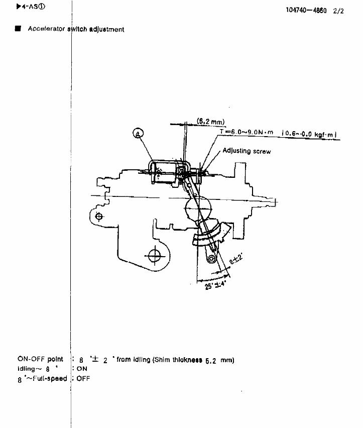
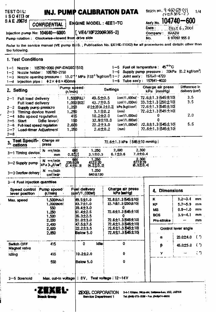
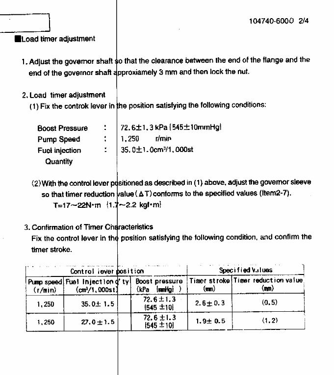
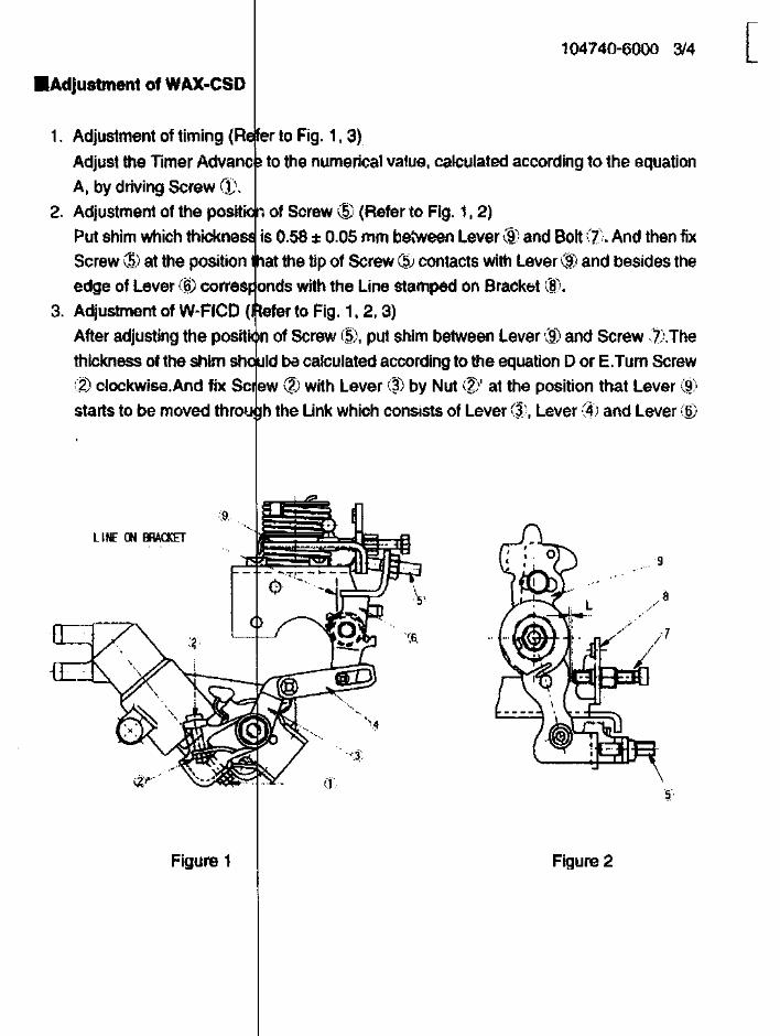
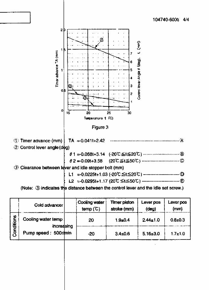
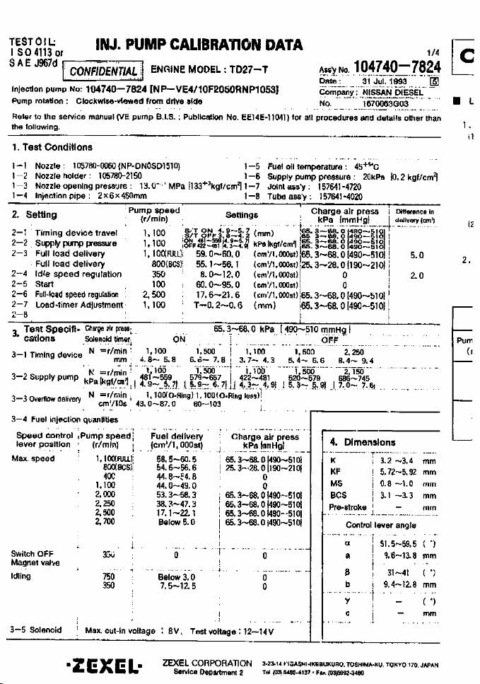

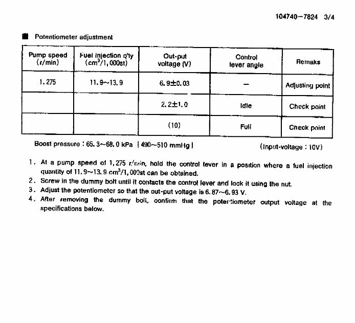
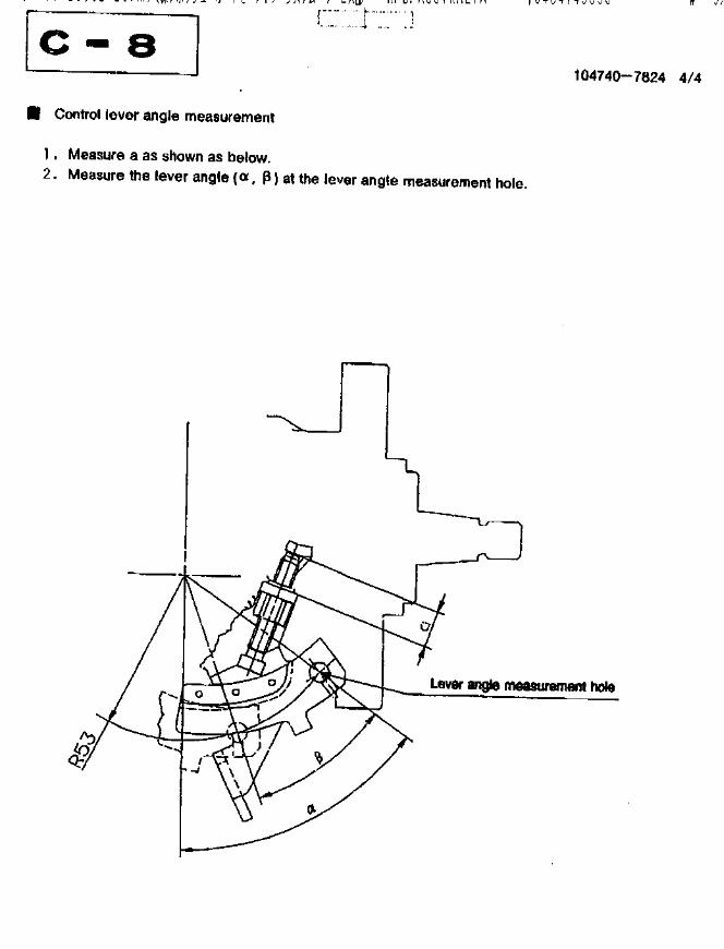
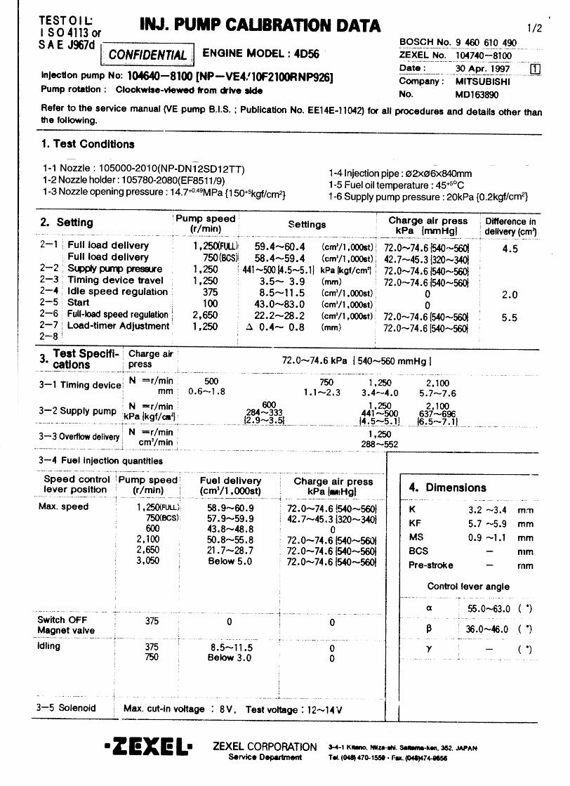
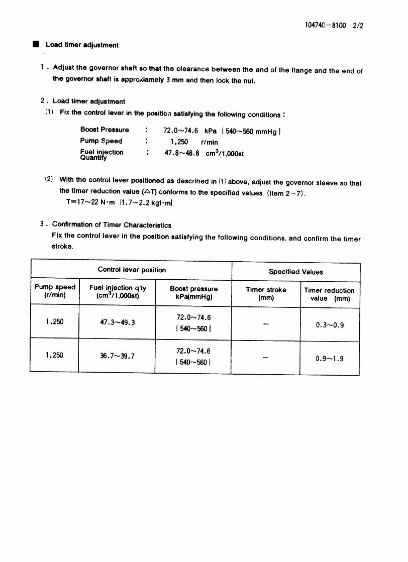
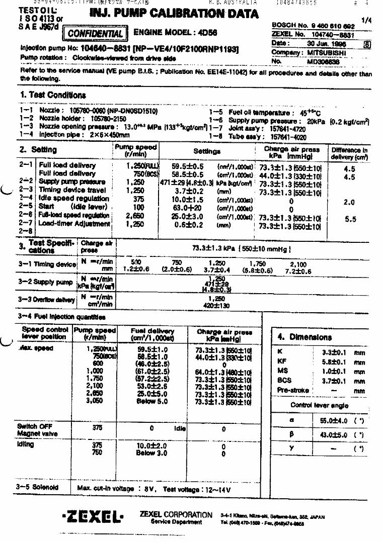
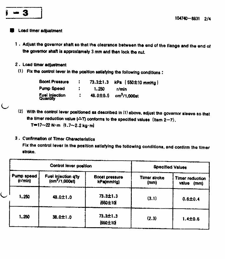

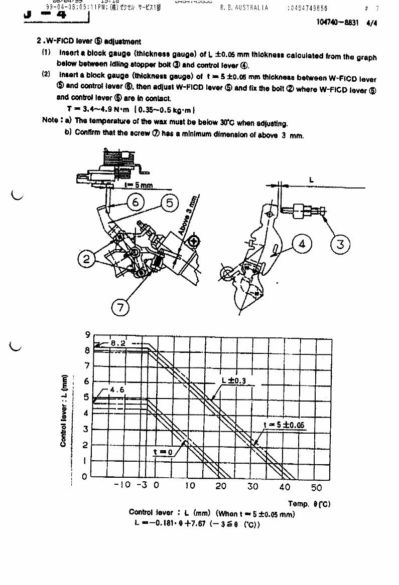
Magnet valveswitch OFF
Assy no.:Date:Company:No.
Refer to the service manual (VE pump B.I.S.: Publication No. EE14E-11042) for all procedures and details other than the following.
1. Test conditions
2. Setting
4. Dimensions
CONFIDENTIAL
TEST OIL:ISO 4113 orSAE J967d ENGINE MODEL:
Injection pump no.:
Pump speed(r/min)
Settings Charge air pressurekPa {mmHg}
Difference indelivery (cm3)
Full load delivery
Supply pump pressureTiming device travelIdle speed regulationStart Full-load speed regulation
2-1
2-22-32-42-52-62-7
(cm3/1,000st)
kPa {kgf/cm2}(mm)(cm3/1,000st)(cm3/1,000st)(cm3/1,000st)
Pump speed(r/min)
Charge air pressurekPa { mmHg }
3.
3-1 Timing device
3-2 Supply pump
3-3 Overflow delivery
N = r/min mm
N = r/minkPa {kgf/cm2}
N = r/mincm3/min
3-4 Fuel injection quantities
Speed controllever position
Fuel delivery(cm3/1,000st)
Maximum speed
Idling
3-5 Solenoid
KKFMSBCSPre-stroke
mmmmmmmmmm
(°)
(°)
(°)
Control lever angle
BOSCH K.K.Sales Automotive Aftermarket Division
3-4-1 Kitano, Niiza-shi, Saitama-ken, 352-8572, JAPAN
Tel. 81-48-475-2521 Fax. 81-48-475-2520
Pump rotation:
[ NP-VE ]clockwise - viewed from drive side
Testspecifications
α
β
γ
INJECTION PUMP CALIBRATION DATA
1,000
1,5501,550 390 1002,100
44.6±0.5
520±20 {5.3±0.2}1.9±0.29.0±2.0
95.0±20.012.7±3.1
3.5
2.0
3.5
730±100 1,440±50 1,550 1,850 0.5 0.5 1.9±0.3 5.7±0.4
1,000 1,550 1,850 314±29 520±20 618±29 {3.2±0.3} {5.3±0.2} {6.3±0.3}
1,550 530±130
2.8±0.15.0±0.11.0±0.1
-0.45±0.02
18.0±4.0
35.0±5.0
-
44.6±1.036.6±2.047.5±2.047.3±2.512.8±3.5Below 7.0
0
9.0±2.0 Below 3.0
390 550
390
1,000 7001,3501,7002,1002,300
104741-103023 Nov 2004ISUZU8 94153 194 0
1/2
4JB1A
4/11F1800RNP251104641-10110
Maximum cut-in voltage: 8 V, Test voltage: 12 - 14 V
Full load delivery
Solenoid Timer
(Full lever)
1-4 Injection pipe: ø2×ø6×840mm1-5 Fuel oil temperature: 45+5°C
1-6 Supply pump pressure: 20kPa {0.2kgf/cm2}
1-1 Nozzle: 105780-0000 (NP-DN12SD12T)1-2 Nozzle holder: 105780-2080 (EF8511/9)1-3 Nozzle opening pressure: 14.7+0.5 MPa {150+5 kgf/cm2}
Full load delivery
(without O-ring)
(with O-ring)
Charge air pressureSolenoid timer
(cm3/1,000st)
(Idle)
ON OFF
104741-1513
use
104741-1514
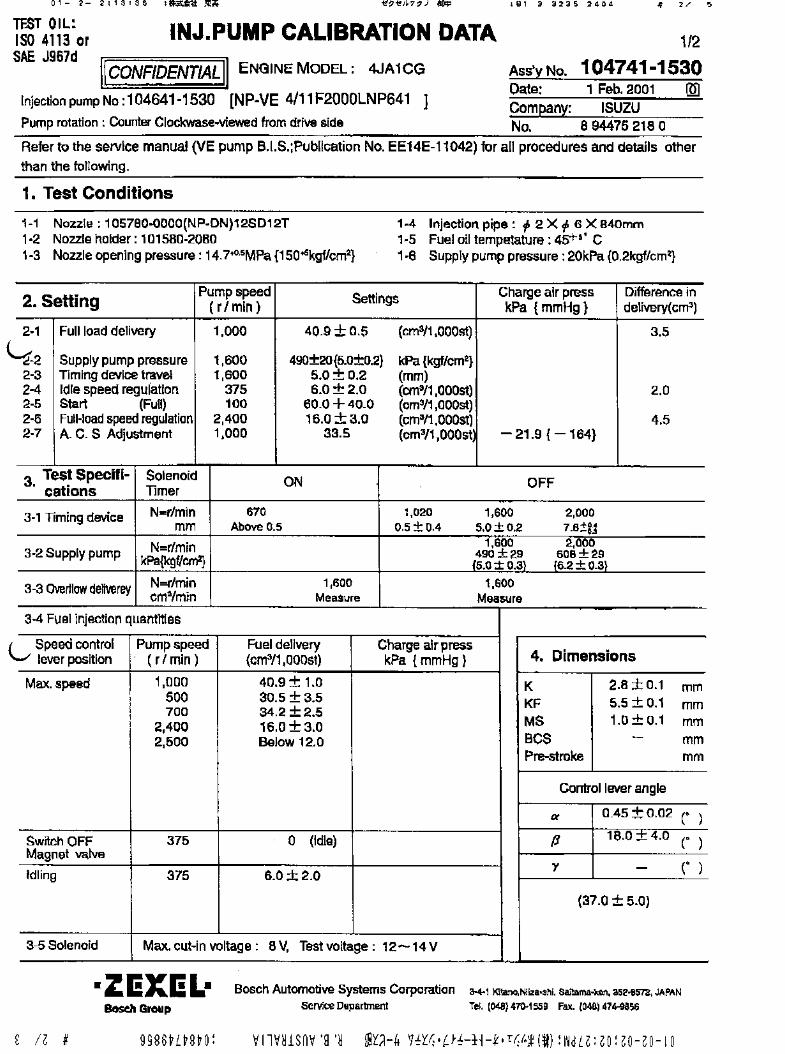
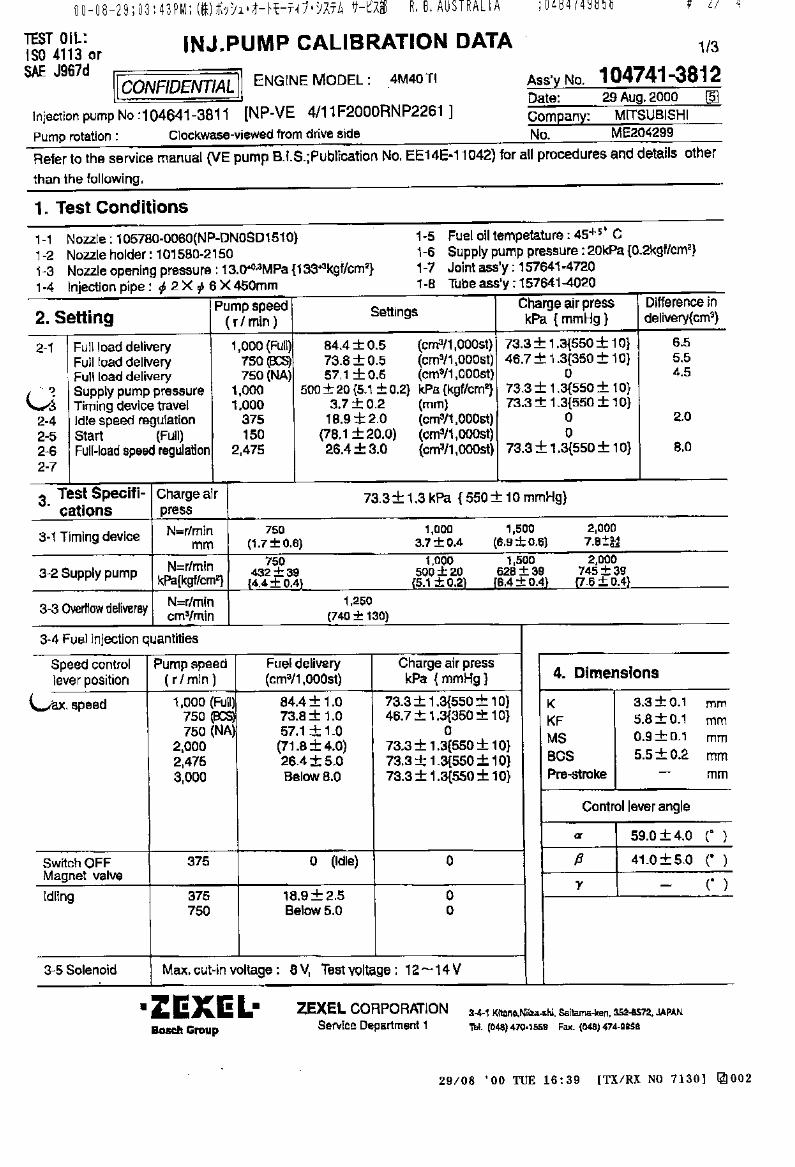
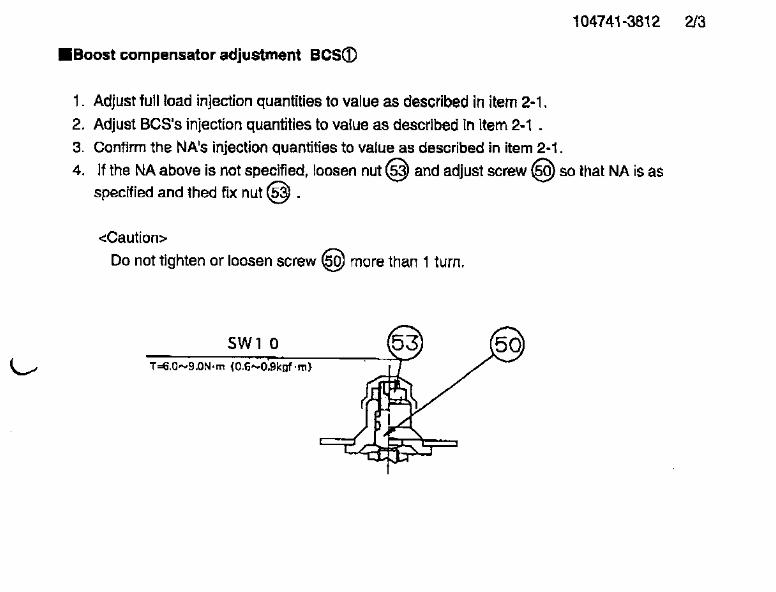
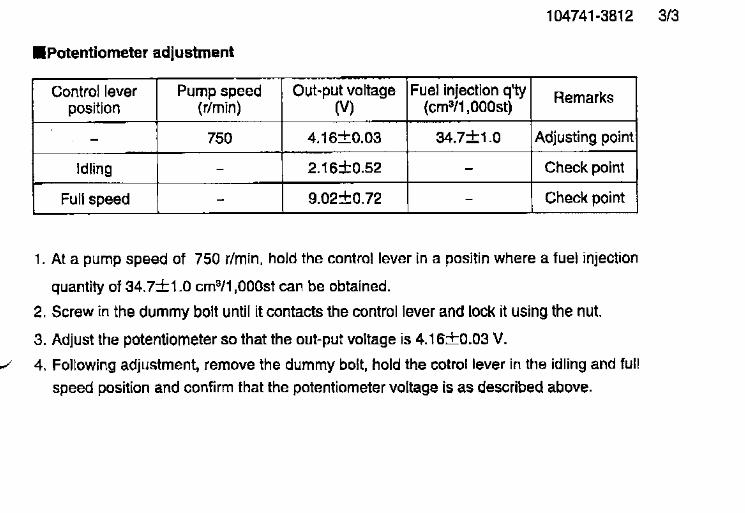
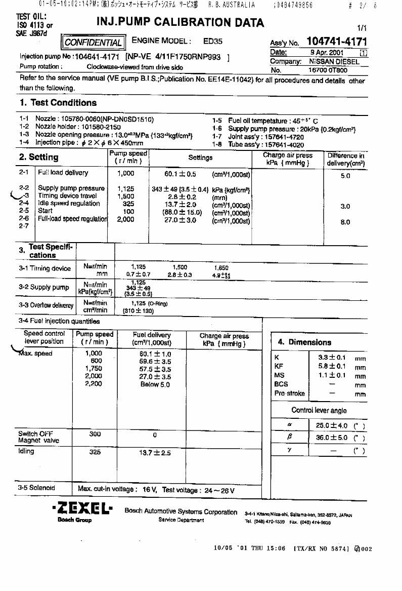
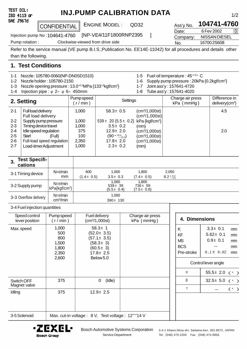
Ass’y No.Date:Company:No.
Refer to the service manual (VE pump B.I.S.;Publication No. EE14E-11042) for all procedures and details other
than the following.
1. Test Conditions
2. Setting
4. Dimensions
CONFIDENTIAL
INJ.PUMP CALIBRATION DATATEST OIL:TEST OIL:TEST OIL:TEST OIL:TEST OIL:ISO 4113ISO 4113ISO 4113ISO 4113ISO 4113 or or or or orSAE J967dSAE J967dSAE J967dSAE J967dSAE J967d
ENGINE MODEL :
Injection pump No : [NP-VE ]Pump rotation : Clockwise-viewed from drive side
Pump speed( r / min )
Settings Charge air presskPa { mmHg }
Difference indelivery(cm3)
Full load delivery
Supply pump pressureTiming device travelIdle speed regulationStartFull-load speed regulation
2-1
2-22-32-42-52-62-7
(cm3/1,000st)
kPa {kgf/cm2}(mm)(cm3/1,000st)(cm3/1,000st)(cm3/1,000st)
Pump speed( r / min )
Charge air presskPa { mmHg }
3. Test Specifi- cations
3-1 Timing device
3-2 Supply pump
3-3 Overflow delivery
N=r/min mm
N=r/minkPa{kgf/cm2}
N=r/mincm3/min
3-4 Fuel injection quantities
Speed controllever position
Fuel delivery(cm3/1,000st)
Max. speed
Switch OFFMagnet valve
Idling
3-5 Solenoid
KKFMSBCSPre-stroke
mmmmmmmmmm
α
β
γ
(°)
(°)
(°)-
Control lever angle
Bosch Automotive Systems CorporationService Department
3-4-1 Kitano,Niiza-shi, Saitama-ken, 352-8572, JAPAN
Tel. (048) 470-1559 Fax. (048) 474-9856
1,000
1,0001,000 375 1002,3501,000
600 1,000 1,800 2,050(1.4±0.5) 3.5±0.3 (7.4±0.5) 8.2+ 0.4 - 0.5
1,000 1,800539±39 736±59
{5.5±0.4} {7.5±0.6}
1,000390±130
6 Fev 2002
104741-47600
NISSAN DIESEL16700 2S608
4/11F1800RNP2395104641-4760
QD32
58.3±0.5
539± 20 {5.5± 0.2} 3.5±0.212.9±2.0
(90+ 20.0 - 15.0)17.8±2.0 2.3±0.2
4.5
2.0
1,000 500 8001,5001,8002,3502,600
1/2
58.3±1(52.0±3.5)(57.1±3.5)(58.3±3)(60.5±3)17.8±2.5Below 5.0
375 0
375 12.9±2.5
3.3±0.15.62±0.10.9±0.1-
0.1±0.02
55.5±2.0
32.5±5.0
Max. cut-in voltage : 8 V, Test voltage : 12~14 V
Load-timer Adjustment (mm)
Full load delivery (cm3/1,000st)
1-1 Nozzle : 105780-0060(NP-DN0SD1510)1-2 Nozzle holder : 105780-21501-3 Nozzle opening pressure : 13.0+0.3MPa {133+3kgf/cm2}1-4 Injection pipe : φ2×φ6×450mm
1-5 Fuel oil temperature : 45+5°C1-6 Supply pump pressure : 20kPa {0.2kgf/cm2}1-7 Joint ass’y : 157641-47201-8 Tube ass’y : 157641-4020
(Idle)
(Full)
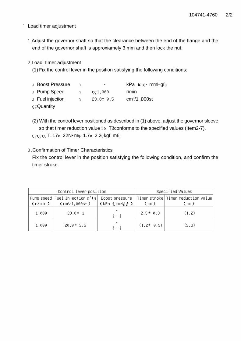
104741-4760 2/2
■Load timer adjustment
1.Adjust the governor shaft so that the clearance between the end of the flange and the
end of the governor shaft is approxiamely 3 mm and then lock the nut.
2.Load timer adjustment
(1) Fix the control lever in the position satisfying the following conditions:
Boost Pressure : - kPa { - mmHg} Pump Speed : 1,000 r/min
Fuel injection : 29.0±0.5 cm3/1,000st
Quantity
(2) With the control lever positioned as described in (1) above, adjust the governor sleeve
so that timer reduction value (ΔT)conforms to the specified values (Item2-7).
T=17~22N・m {1.7~2.2 kgf・m}
3.Confirmation of Timer Characteristics
Fix the control lever in the position satisfying the following condition, and confirm the
timer stroke.
Control lever position Specified ValuesPump speed(r/min)
Fuel Injection q'ty(cm3/1,000st)
Boost pressure(kPa {mmHg})
Timer stroke(mm)
Timer reduction value(mm)
1,000 29.0 1 -{ - } 2.3 0.3 (1.2)
1,000 20.0 2.5 -{ - } (1.2 0.5) (2.3)±
±
±
±
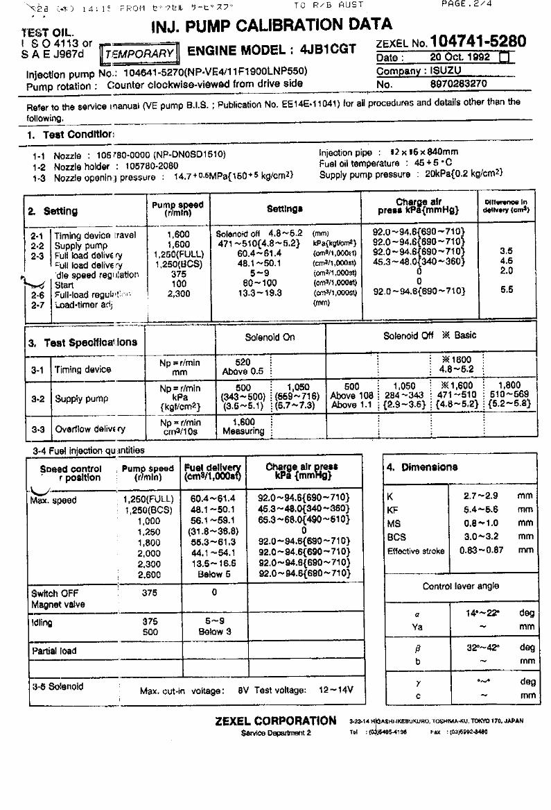
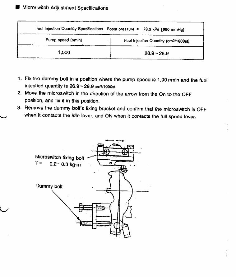

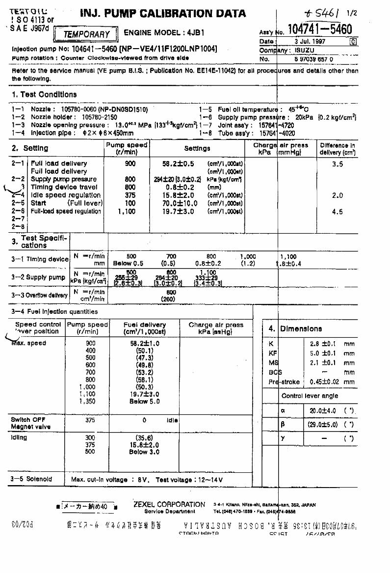
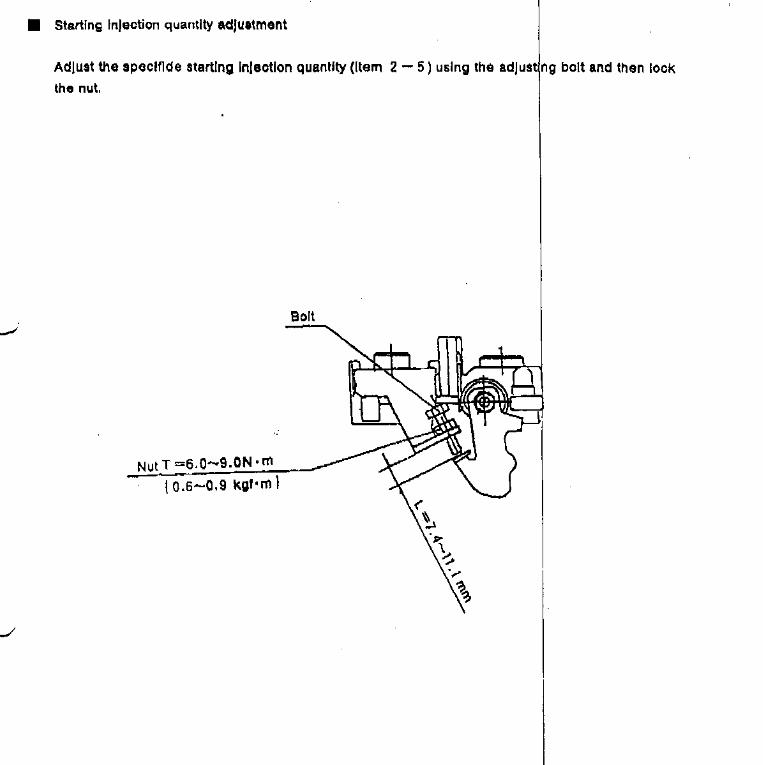

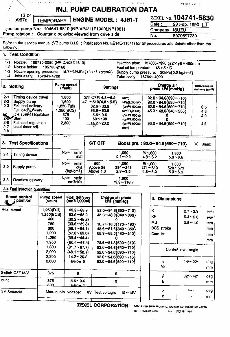
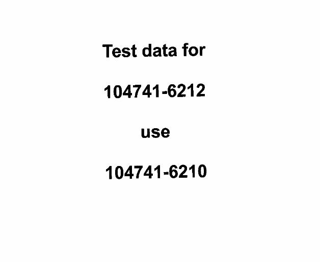

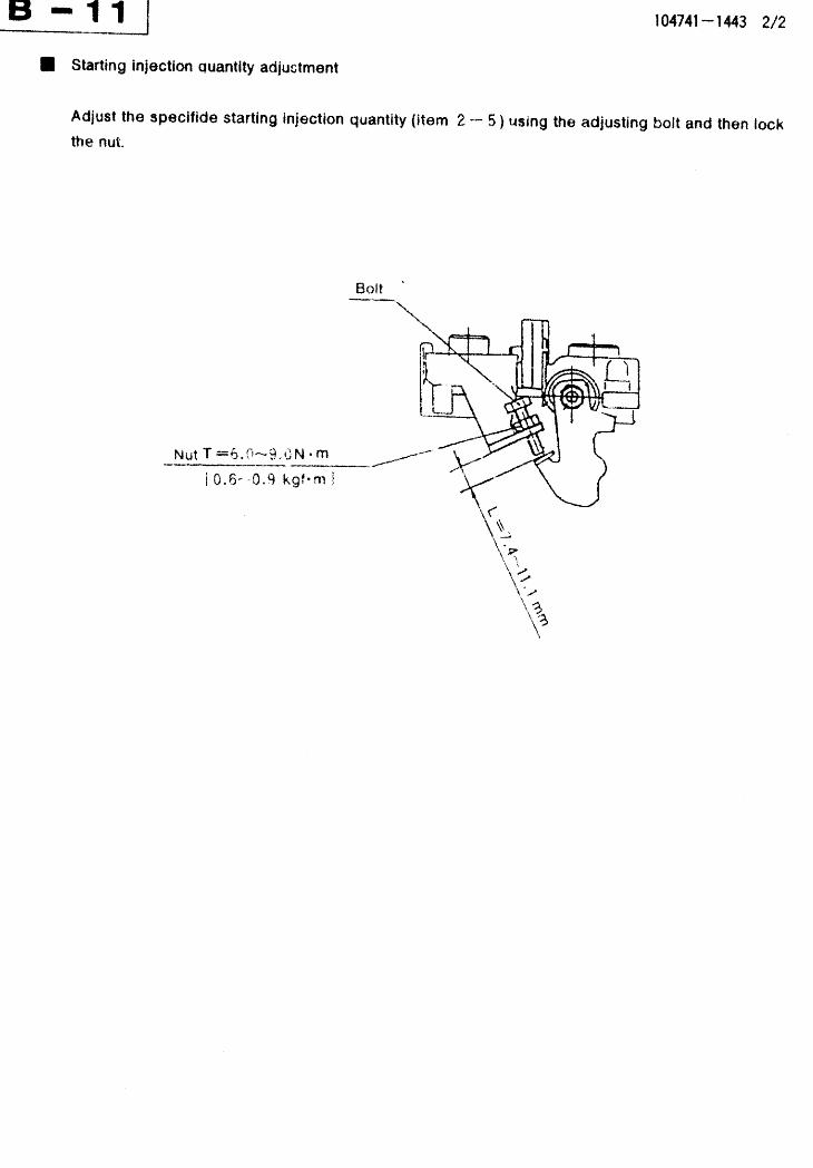
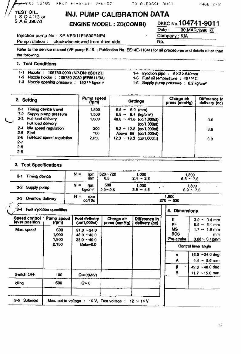
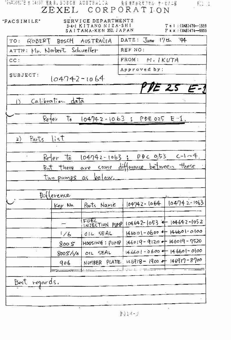


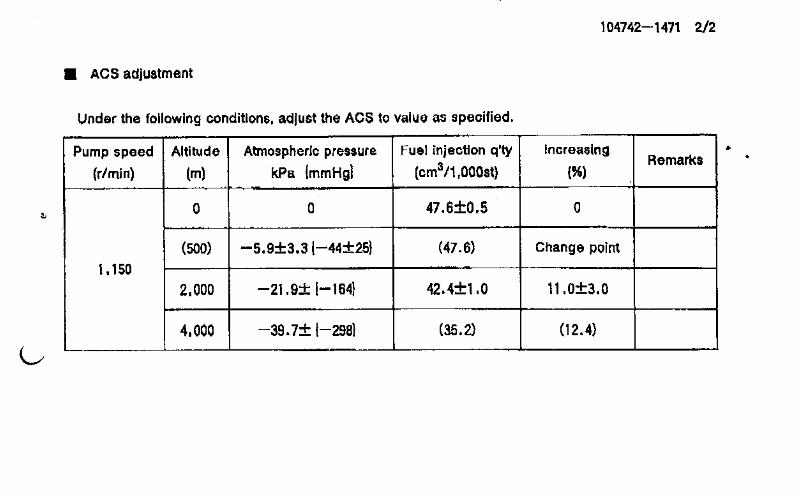
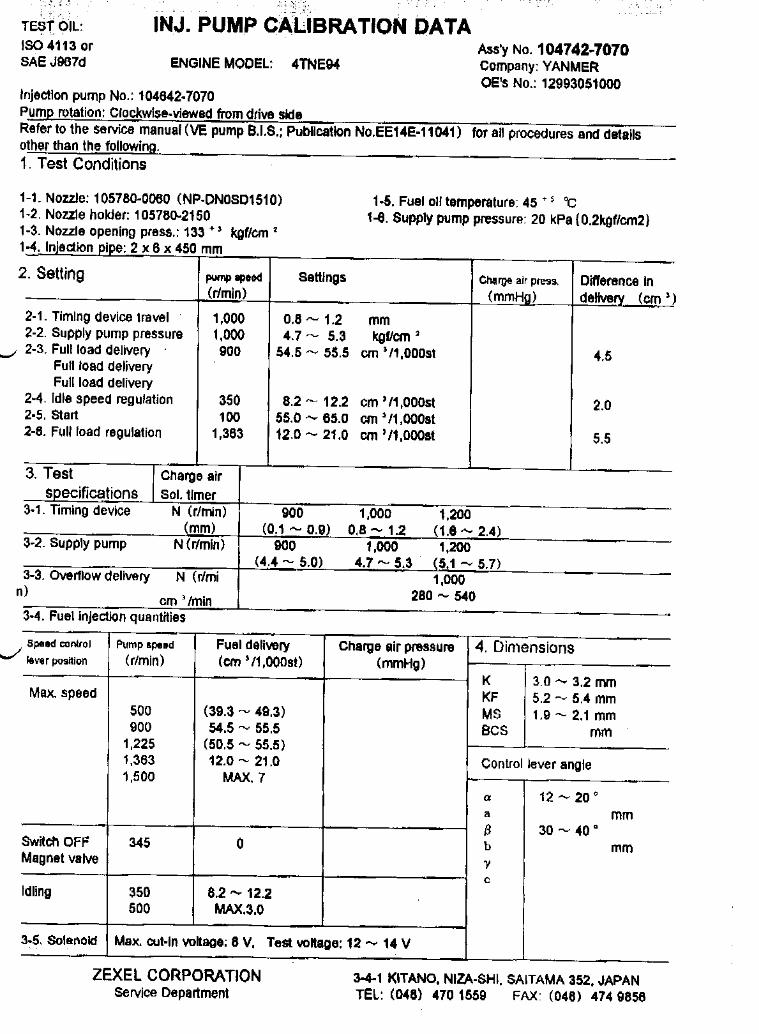

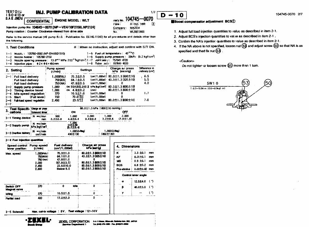


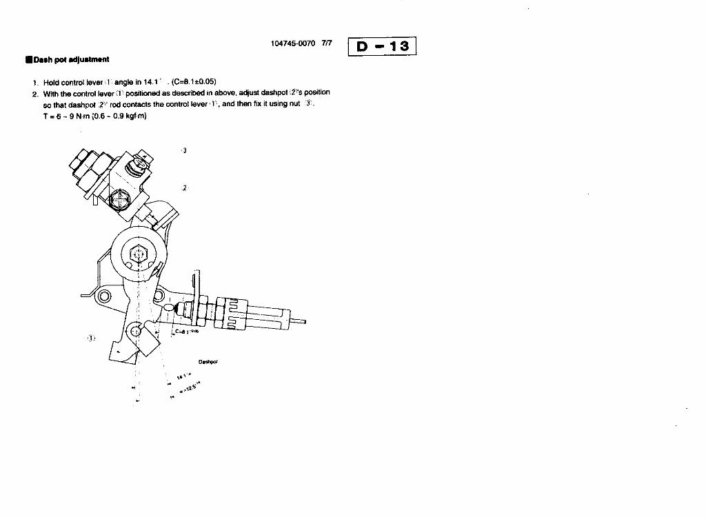
104745-0074 ZEXEL test values diesel fuel-injection equipment 28/05/07 13:16:08 Page 1
ZEXEL Ass'y No. 104745-0074
Bosch Ass'y No. 9 460 614 810
Bosch Typecode
Engine Type WLT
Manufacturer MAZDA
Edition date 23/10/06 (5)
1 Adjustment conditions
CAT Designation Unit Set value min. max. Actual values OT
Test oil ISO4113orSAEJ967d
1404 Test oil
P Test Oil Temperature degC 45 45 50
Nozzle 105780-0060
Bosch type code NP-DN0SD1510
Nozzle holder 105780-2150
P Opening Pressure MPa 13 13 13.3
P Opening Pressure kgf/cm2 133 133 136
Injection pipe 157805-7320
P Injection pipe mm 2-6-450
Inside diameter - outside diameter - length (mm)
Joint assembly 157641-4720
Tube assembly 157641-4020
P Transfer pump pressure kPa 20 20 20
P Transfer pump pressure kgf/cm2 0.2 0.2 0.2
Direction of rotation (viewed from drive side) L
Left
(Sorenoid Timer Adjustment Condition) ON
With S/T O-ring; S/T ON.
2 Adjustment specification
2.1 Full load delivery
CAT Designation Unit Set value min. max. Actual values OT
P Pump speed r/min 750 750 750
P Boost pressure kPa 0 0 0
P Boost pressure mmHg 0 0 0
S Average injection quantity mm3/st. 47.9 47.4 48.4
S Differnce in delivery mm3/st. 4 4
P Basic *
P Oil temperature degC 50 48 52
Remarks
NA
CAT Designation Unit Set value min. max. Actual values OT
P Pump speed r/min 750 750 750
P Boost pressure kPa 43.3 42 44.6
P Boost pressure mmHg 325 315 335
S Average injection quantity mm3/st. 64.1 63.6 64.6
S Differnce in delivery mm3/st. 5.5 5.5
P Basic *
P Oil temperature degC 50 48 52
Remarks
CBS
S = Setting value, C = Check value)OT = Outside Tolerance (X is set)
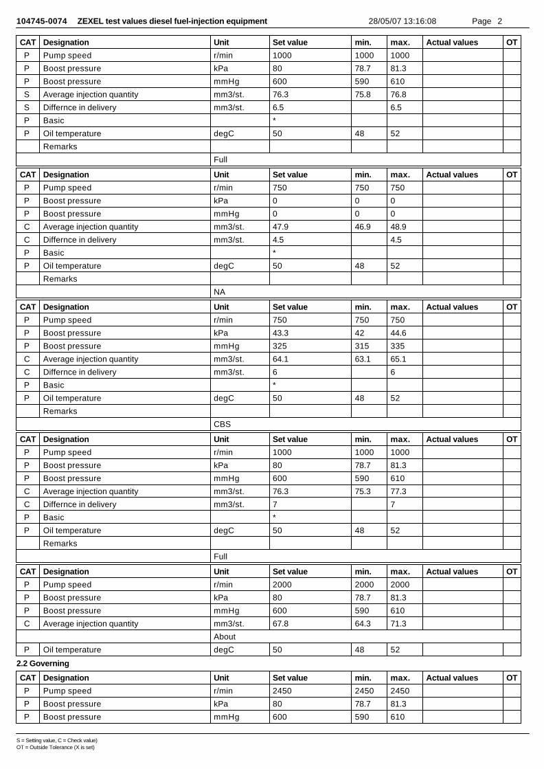
104745-0074 ZEXEL test values diesel fuel-injection equipment 28/05/07 13:16:08 Page 2
CAT Designation Unit Set value min. max. Actual values OT
P Pump speed r/min 1000 1000 1000
P Boost pressure kPa 80 78.7 81.3
P Boost pressure mmHg 600 590 610
S Average injection quantity mm3/st. 76.3 75.8 76.8
S Differnce in delivery mm3/st. 6.5 6.5
P Basic *
P Oil temperature degC 50 48 52
Remarks
Full
CAT Designation Unit Set value min. max. Actual values OT
P Pump speed r/min 750 750 750
P Boost pressure kPa 0 0 0
P Boost pressure mmHg 0 0 0
C Average injection quantity mm3/st. 47.9 46.9 48.9
C Differnce in delivery mm3/st. 4.5 4.5
P Basic *
P Oil temperature degC 50 48 52
Remarks
NA
CAT Designation Unit Set value min. max. Actual values OT
P Pump speed r/min 750 750 750
P Boost pressure kPa 43.3 42 44.6
P Boost pressure mmHg 325 315 335
C Average injection quantity mm3/st. 64.1 63.1 65.1
C Differnce in delivery mm3/st. 6 6
P Basic *
P Oil temperature degC 50 48 52
Remarks
CBS
CAT Designation Unit Set value min. max. Actual values OT
P Pump speed r/min 1000 1000 1000
P Boost pressure kPa 80 78.7 81.3
P Boost pressure mmHg 600 590 610
C Average injection quantity mm3/st. 76.3 75.3 77.3
C Differnce in delivery mm3/st. 7 7
P Basic *
P Oil temperature degC 50 48 52
Remarks
Full
CAT Designation Unit Set value min. max. Actual values OT
P Pump speed r/min 2000 2000 2000
P Boost pressure kPa 80 78.7 81.3
P Boost pressure mmHg 600 590 610
C Average injection quantity mm3/st. 67.8 64.3 71.3
About
P Oil temperature degC 50 48 52
2.2 Governing
CAT Designation Unit Set value min. max. Actual values OT
P Pump speed r/min 2450 2450 2450
P Boost pressure kPa 80 78.7 81.3
P Boost pressure mmHg 600 590 610
S = Setting value, C = Check value)OT = Outside Tolerance (X is set)
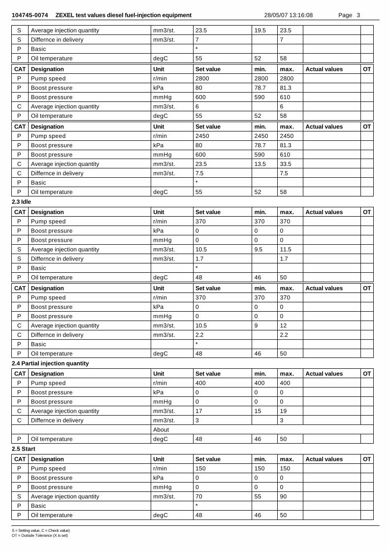
104745-0074 ZEXEL test values diesel fuel-injection equipment 28/05/07 13:16:08 Page 3
S Average injection quantity mm3/st. 23.5 19.5 23.5
S Differnce in delivery mm3/st. 7 7
P Basic *
P Oil temperature degC 55 52 58
CAT Designation Unit Set value min. max. Actual values OT
P Pump speed r/min 2800 2800 2800
P Boost pressure kPa 80 78.7 81.3
P Boost pressure mmHg 600 590 610
C Average injection quantity mm3/st. 6 6
P Oil temperature degC 55 52 58
CAT Designation Unit Set value min. max. Actual values OT
P Pump speed r/min 2450 2450 2450
P Boost pressure kPa 80 78.7 81.3
P Boost pressure mmHg 600 590 610
C Average injection quantity mm3/st. 23.5 13.5 33.5
C Differnce in delivery mm3/st. 7.5 7.5
P Basic *
P Oil temperature degC 55 52 58
2.3 Idle
CAT Designation Unit Set value min. max. Actual values OT
P Pump speed r/min 370 370 370
P Boost pressure kPa 0 0 0
P Boost pressure mmHg 0 0 0
S Average injection quantity mm3/st. 10.5 9.5 11.5
S Differnce in delivery mm3/st. 1.7 1.7
P Basic *
P Oil temperature degC 48 46 50
CAT Designation Unit Set value min. max. Actual values OT
P Pump speed r/min 370 370 370
P Boost pressure kPa 0 0 0
P Boost pressure mmHg 0 0 0
C Average injection quantity mm3/st. 10.5 9 12
C Differnce in delivery mm3/st. 2.2 2.2
P Basic *
P Oil temperature degC 48 46 50
2.4 Partial injection quantity
CAT Designation Unit Set value min. max. Actual values OT
P Pump speed r/min 400 400 400
P Boost pressure kPa 0 0 0
P Boost pressure mmHg 0 0 0
C Average injection quantity mm3/st. 17 15 19
C Differnce in delivery mm3/st. 3 3
About
P Oil temperature degC 48 46 50
2.5 Start
CAT Designation Unit Set value min. max. Actual values OT
P Pump speed r/min 150 150 150
P Boost pressure kPa 0 0 0
P Boost pressure mmHg 0 0 0
S Average injection quantity mm3/st. 70 55 90
P Basic *
P Oil temperature degC 48 46 50
S = Setting value, C = Check value)OT = Outside Tolerance (X is set)
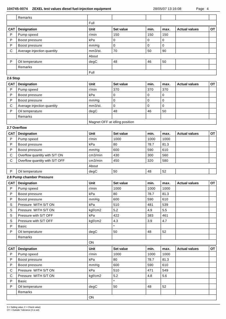
104745-0074 ZEXEL test values diesel fuel-injection equipment 28/05/07 13:16:08 Page 4
Remarks
Full
CAT Designation Unit Set value min. max. Actual values OT
P Pump speed r/min 150 150 150
P Boost pressure kPa 0 0 0
P Boost pressure mmHg 0 0 0
C Average injection quantity mm3/st. 70 50 90
About
P Oil temperature degC 48 46 50
Remarks
Full
2.6 Stop
CAT Designation Unit Set value min. max. Actual values OT
P Pump speed r/min 370 370 370
P Boost pressure kPa 0 0 0
P Boost pressure mmHg 0 0 0
C Average injection quantity mm3/st. 0 0 0
P Oil temperature degC 48 46 50
Remarks
Magnet OFF at idling position
2.7 Overflow
CAT Designation Unit Set value min. max. Actual values OT
P Pump speed r/min 1000 1000 1000
P Boost pressure kPa 80 78.7 81.3
P Boost pressure mmHg 600 590 610
C Overflow quantity with S/T ON cm3/min 430 300 560
C Overflow quantity with S/T OFF cm3/min 450 320 580
About
P Oil temperature degC 50 48 52
2.8 Pump chamber Pressure
CAT Designation Unit Set value min. max. Actual values OT
P Pump speed r/min 1000 1000 1000
P Boost pressure kPa 80 78.7 81.3
P Boost pressure mmHg 600 590 610
S Pressure WITH S/T ON kPa 510 481 539
S Pressure WITH S/T ON kgf/cm2 5.2 4.9 5.5
S Pressure with S/T OFF kPa 422 383 461
S Pressure with S/T OFF kgf/cm2 4.3 3.9 4.7
P Basic *
P Oil temperature degC 50 48 52
Remarks
ON
CAT Designation Unit Set value min. max. Actual values OT
P Pump speed r/min 1000 1000 1000
P Boost pressure kPa 80 78.7 81.3
P Boost pressure mmHg 600 590 610
C Pressure WITH S/T ON kPa 510 471 549
C Pressure WITH S/T ON kgf/cm2 5.2 4.8 5.6
P Basic *
P Oil temperature degC 50 48 52
Remarks
ON
S = Setting value, C = Check value)OT = Outside Tolerance (X is set)
104745-0074 ZEXEL test values diesel fuel-injection equipment 28/05/07 13:16:08 Page 5
2.9 Timer
CAT Designation Unit Set value min. max. Actual values OT
P Pump speed r/min 1000 1000 1000
P Boost pressure kPa 80 78.7 81.3
P Boost pressure mmHg 600 590 610
S Timer stroke with S/T ON mm 4.8 4.6 5
S Timer stroke with S/T OFF mm 3.2 2.8 3.6
P Basic *
P Oil temperature degC 50 48 52
Remarks
ON
CAT Designation Unit Set value min. max. Actual values OT
P Pump speed r/min 500 500 500
P Boost pressure kPa 80 78.7 81.3
P Boost pressure mmHg 600 590 610
C Timer stroke with S/T ON mm 2.2 1.4 3
P Oil temperature degC 48 46 50
CAT Designation Unit Set value min. max. Actual values OT
P Pump speed r/min 1000 1000 1000
P Boost pressure kPa 80 78.7 81.3
P Boost pressure mmHg 600 590 610
C Timer stroke with S/T ON mm 4.8 4.4 5.2
C Timer stroke with S/T OFF mm 3.2 2.6 3.8
P Basic *
P Oil temperature degC 50 48 52
Remarks
ON
CAT Designation Unit Set value min. max. Actual values OT
P Pump speed r/min 2000 2000 2000
P Boost pressure kPa 80 78.7 81.3
P Boost pressure mmHg 600 590 610
C Timer stroke with S/T ON mm 9.4 8.6 10.2
C Timer stroke with S/T OFF mm 7.8 6.8 8.8
About
P Oil temperature degC 50 48 52
2.10 Magnet
CAT Designation Unit Set value min. max. Actual values OT
C MAX applied voltage V 8 8 8
P Test voltage V 13 12 14
2.11 Additional device adjustment
S = Setting value, C = Check value)OT = Outside Tolerance (X is set)

104745-0074 ZEXEL test values diesel fuel-injection equipment 28/05/07 13:16:08 Page 6
2.11.1 Additional device 1
Name CONTROL STANDARD AT IDLING
Standards for idle difference in delivery controlAfter idle adjustment, measure the idle injection quantities of (A) to (D).Install the colored rings to the delivery valve holders (A) to (D) in accordance with the table.(A): A cylinder (B) :B cylinder (C) : C cylinder (D): D cylinder(E): Collar ring(F): (A) >= (C)(G): (C) > (A)(H): (A) - (C) or (C) - (A)(I): 0.2, 0.1(mm3/st)(J): (B) - (D) or (D) - (B)(K): Ring color(L): At least 0.6 mm3/st(M): 0.3, 0.4, 0.5 (mm3/st)(N): 0.2, 0.1, 0.0 (mm3/st)(O): (B) >= (D)(P): (D) > (B)(T): Yellow(U): White(V): Red
S = Setting value, C = Check value)OT = Outside Tolerance (X is set)
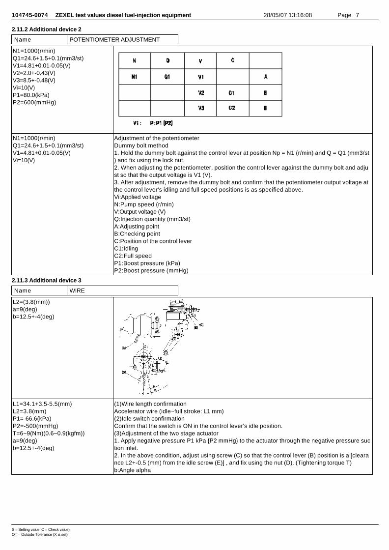
104745-0074 ZEXEL test values diesel fuel-injection equipment 28/05/07 13:16:08 Page 7
2.11.2 Additional device 2
Name POTENTIOMETER ADJUSTMENT
N1=1000(r/min)Q1=24.6+1.5+0.1(mm3/st)V1=4.81+0.01-0.05(V)V2=2.0+-0.43(V)V3=8.5+-0.48(V)Vi=10(V)P1=80.0(kPa)P2=600(mmHg)
N1=1000(r/min)Q1=24.6+1.5+0.1(mm3/st)V1=4.81+0.01-0.05(V)Vi=10(V)
Adjustment of the potentiometerDummy bolt method1. Hold the dummy bolt against the control lever at position Np = N1 (r/min) and Q = Q1 (mm3/st) and fix using the lock nut.2. When adjusting the potentiometer, position the control lever against the dummy bolt and adjust so that the output voltage is V1 (V).3. After adjustment, remove the dummy bolt and confirm that the potentiometer output voltage atthe control lever's idling and full speed positions is as specified above.Vi:Applied voltageN:Pump speed (r/min)V:Output voltage (V)Q:Injection quantity (mm3/st)A:Adjusting pointB:Checking pointC:Position of the control leverC1:IdlingC2:Full speedP1:Boost pressure (kPa)P2:Boost pressure (mmHg)
2.11.3 Additional device 3
Name WIRE
L2=(3.8(mm))a=9(deg)b=12.5+-4(deg)
L1=34.1+3.5-5.5(mm)L2=3.8(mm)P1=-66.6(kPa)P2=-500(mmHg)T=6~9(Nm)(0.6~0.9(kgfm))a=9(deg)b=12.5+-4(deg)
(1)Wire length confirmationAccelerator wire (idle~full stroke: L1 mm)(2)Idle switch confirmationConfirm that the switch is ON in the control lever's idle position.(3)Adjustment of the two stage actuator1. Apply negative pressure P1 kPa {P2 mmHg} to the actuator through the negative pressure suction inlet.2. In the above condition, adjust using screw (C) so that the control lever (B) position is a [clearance L2+-0.5 (mm) from the idle screw (E)] , and fix using the nut (D). (Tightening torque T)b:Angle alpha
S = Setting value, C = Check value)OT = Outside Tolerance (X is set)
104745-0074 ZEXEL test values diesel fuel-injection equipment 28/05/07 13:16:08 Page 8
2.11.4 Additional device 4
Name DASHPOT ADJUSTMENT
L=8.1+-0.05(mm)a=14.1(deg)b=12.5+-4(deg)
L=8.1+-0.05(mm)T=6~9(N-m)(0.6~0.9(kgf-m))a=14.1(deg)b=12.5+-4(deg)
Adjustment of the dash pot1. Hold the control lever (A) at position a (clearance L).2. In the above condition, adjust the position of the dash pot so that the end of the dash pot (B) contacts the control lever (A) and fix using the nut (C).(Tightening torque T)D:Dash pot contact positionb:Angle alpha
3 Assembly dimension
CAT Designation Unit Set value min. max. Actual values OT
S K dimension mm 3.3 3.2 3.4
S KF dimension mm 6.01 5.91 6.11
S MS dimension mm 0.9 0.8 1
S BCS stroke mm 6.8 6.6 7
S Pre-stroke mm 0.03 0.01 0.05
S Control lever angle alpha deg. 12.5 8.5 16.5
S Control lever angle beta deg. 40 37 43
S = Setting value, C = Check value)OT = Outside Tolerance (X is set)
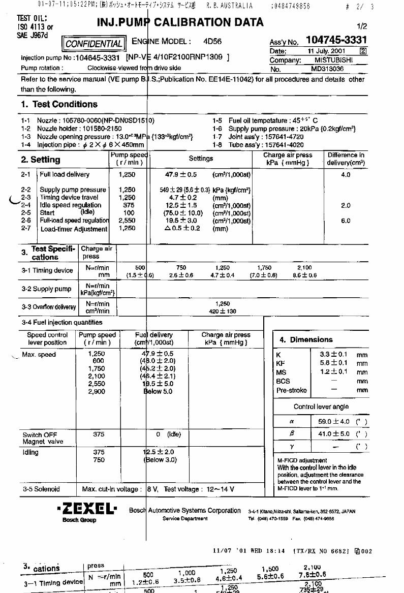


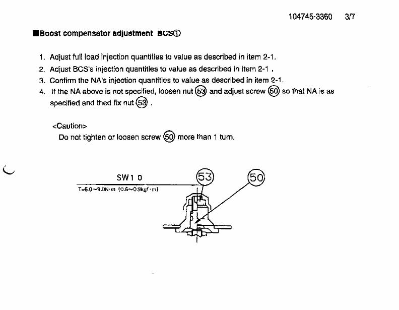
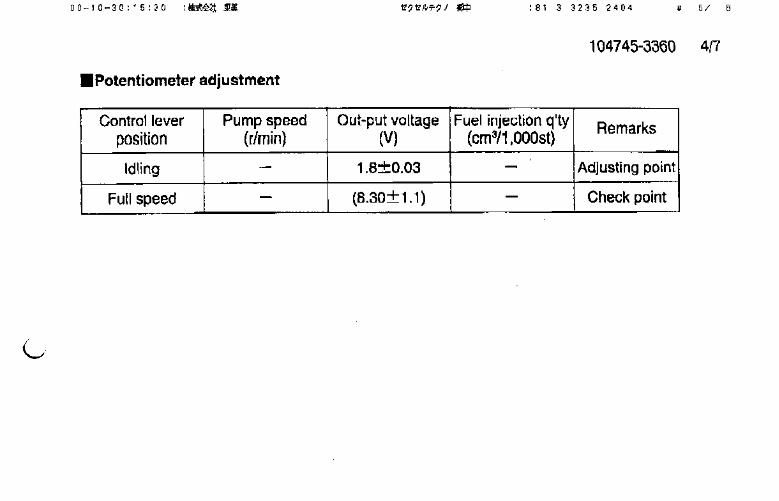
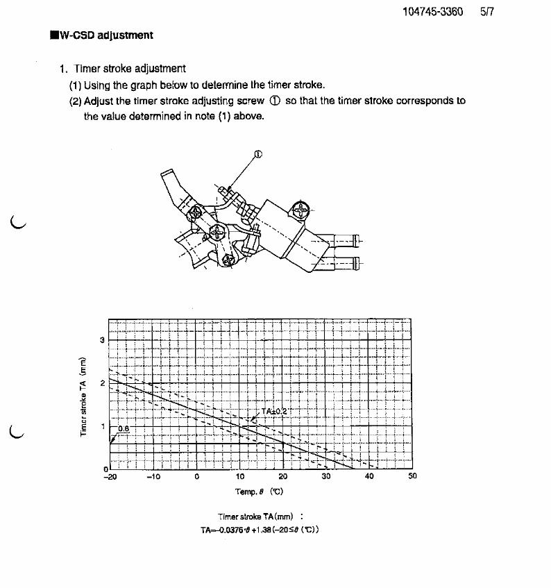
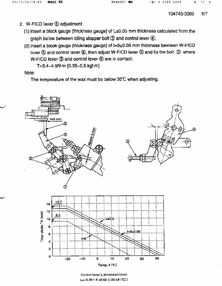
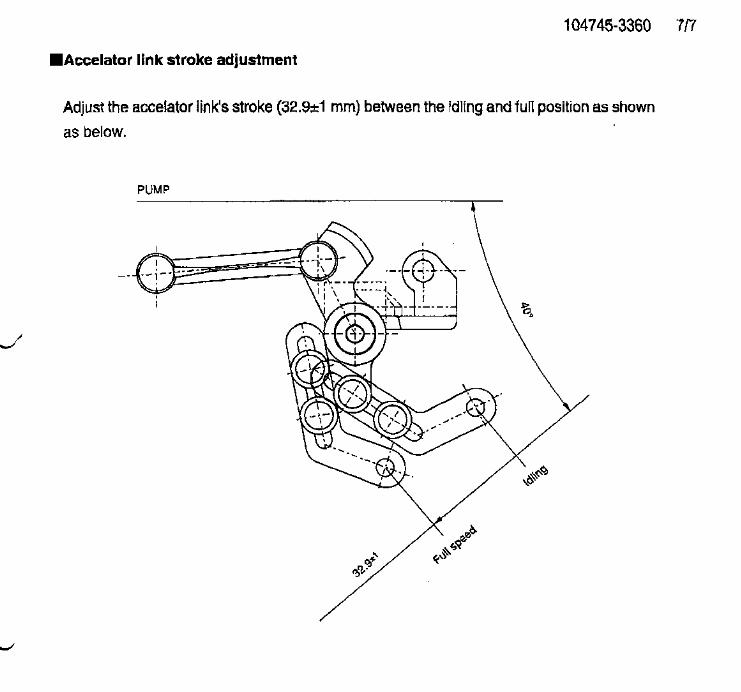
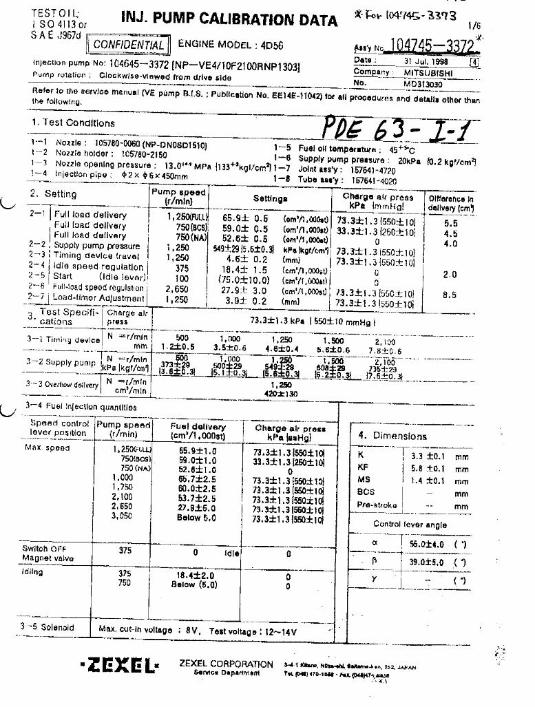
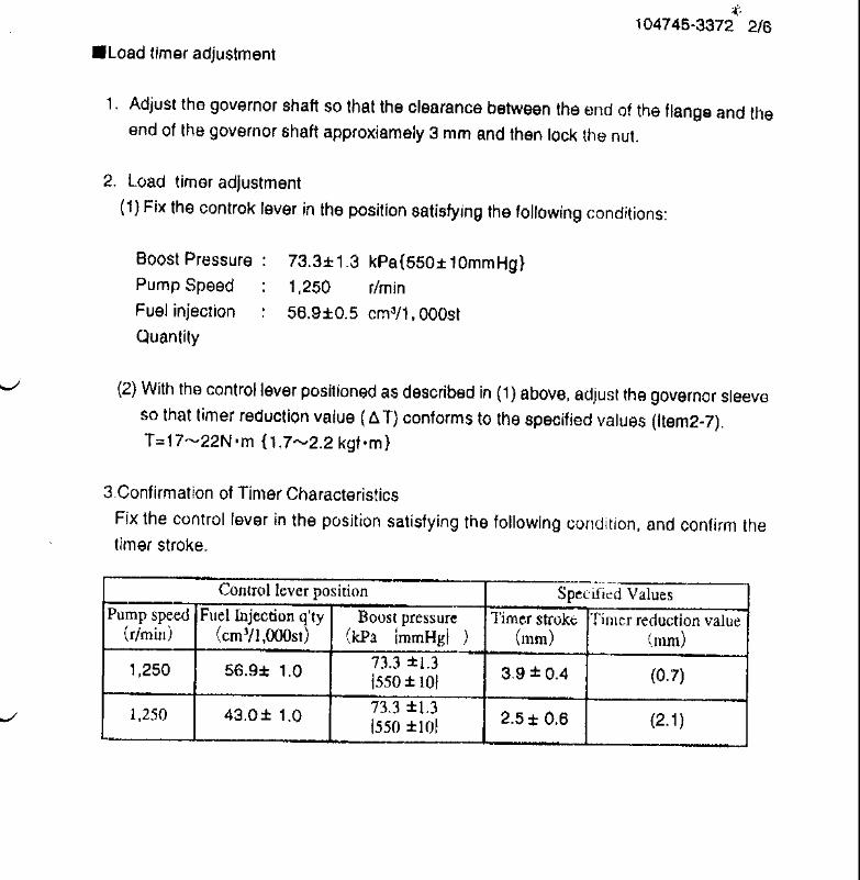

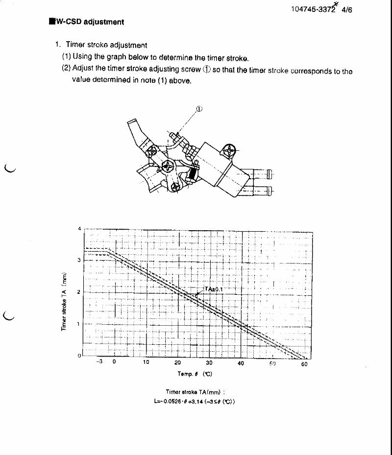
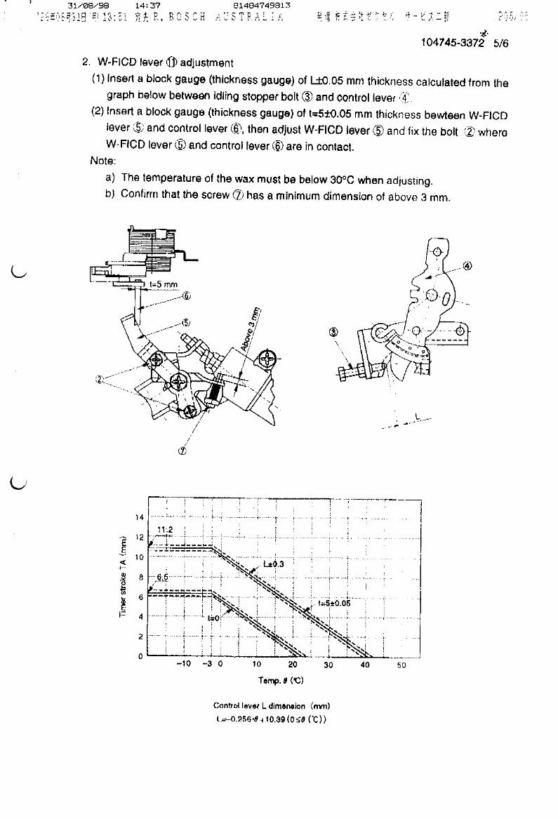
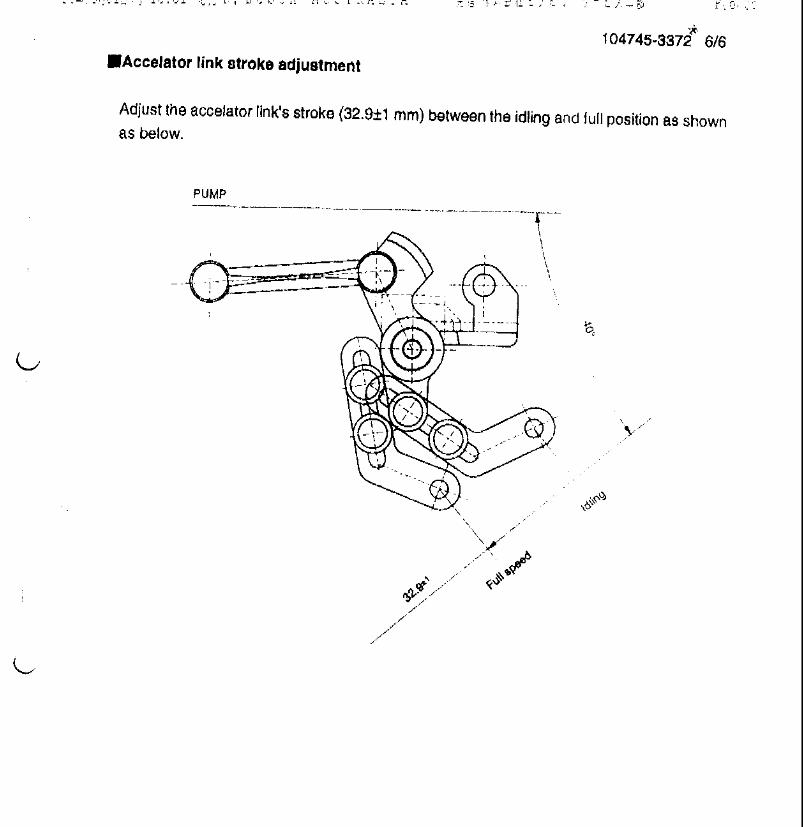
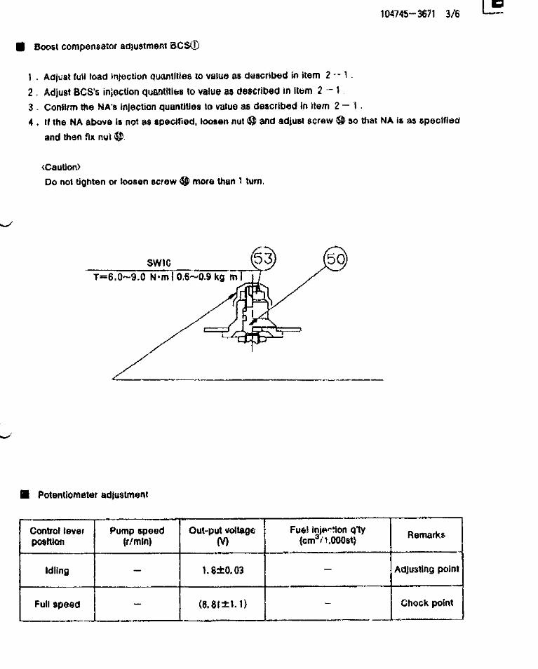
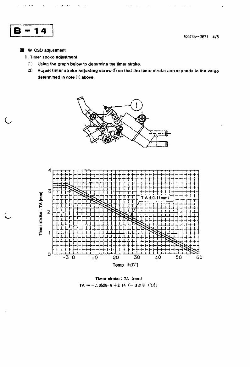
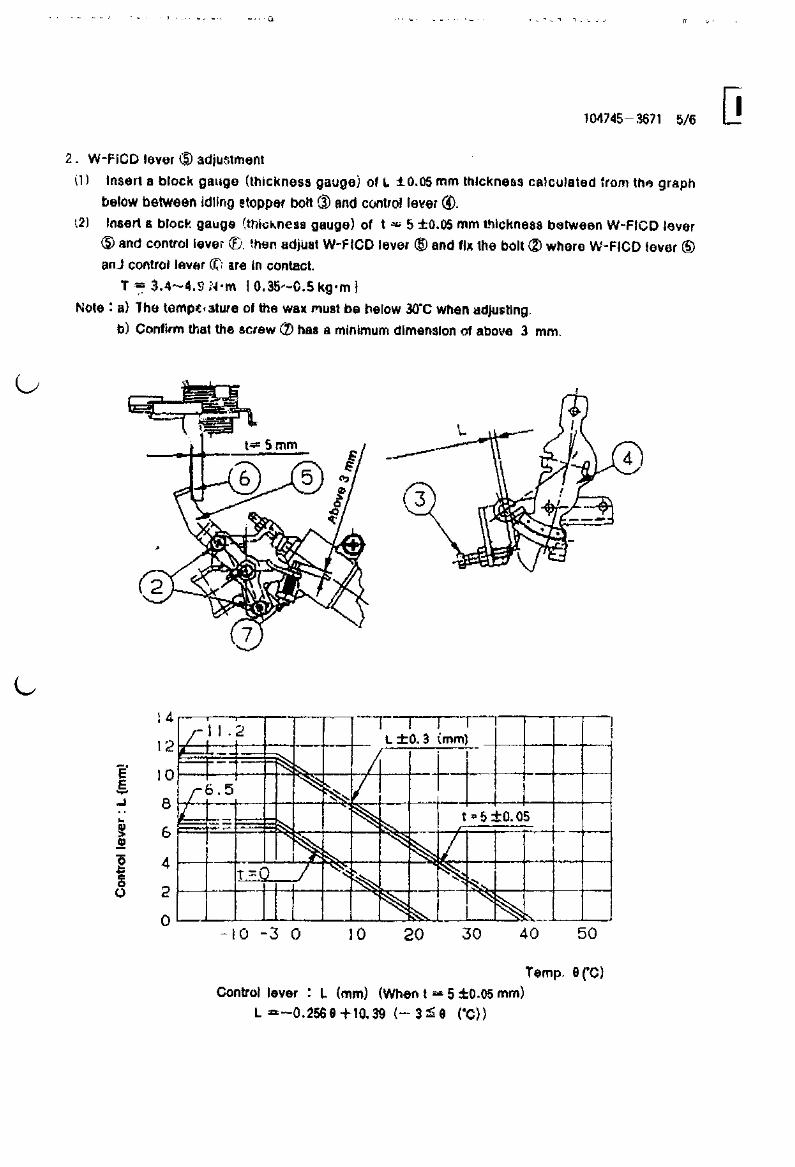
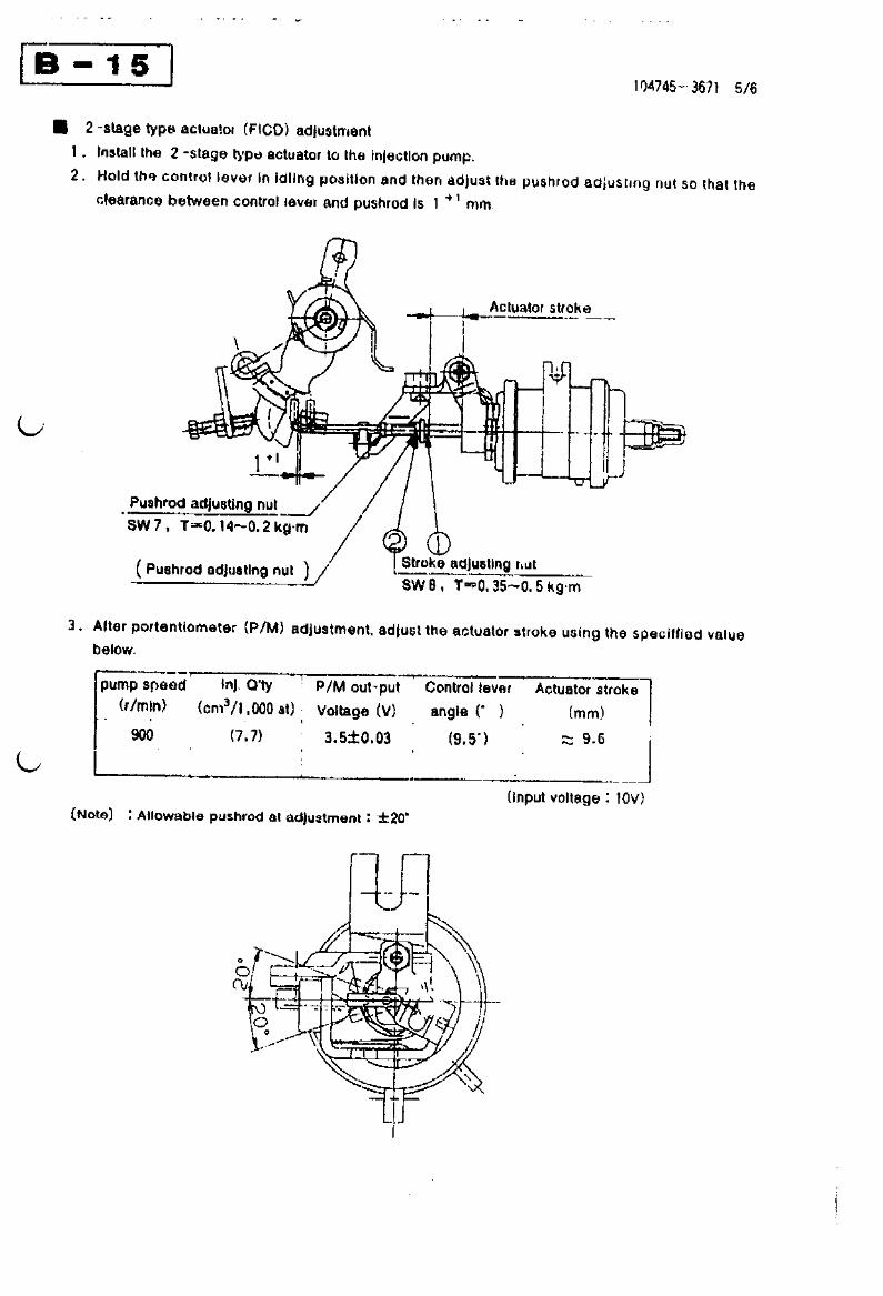
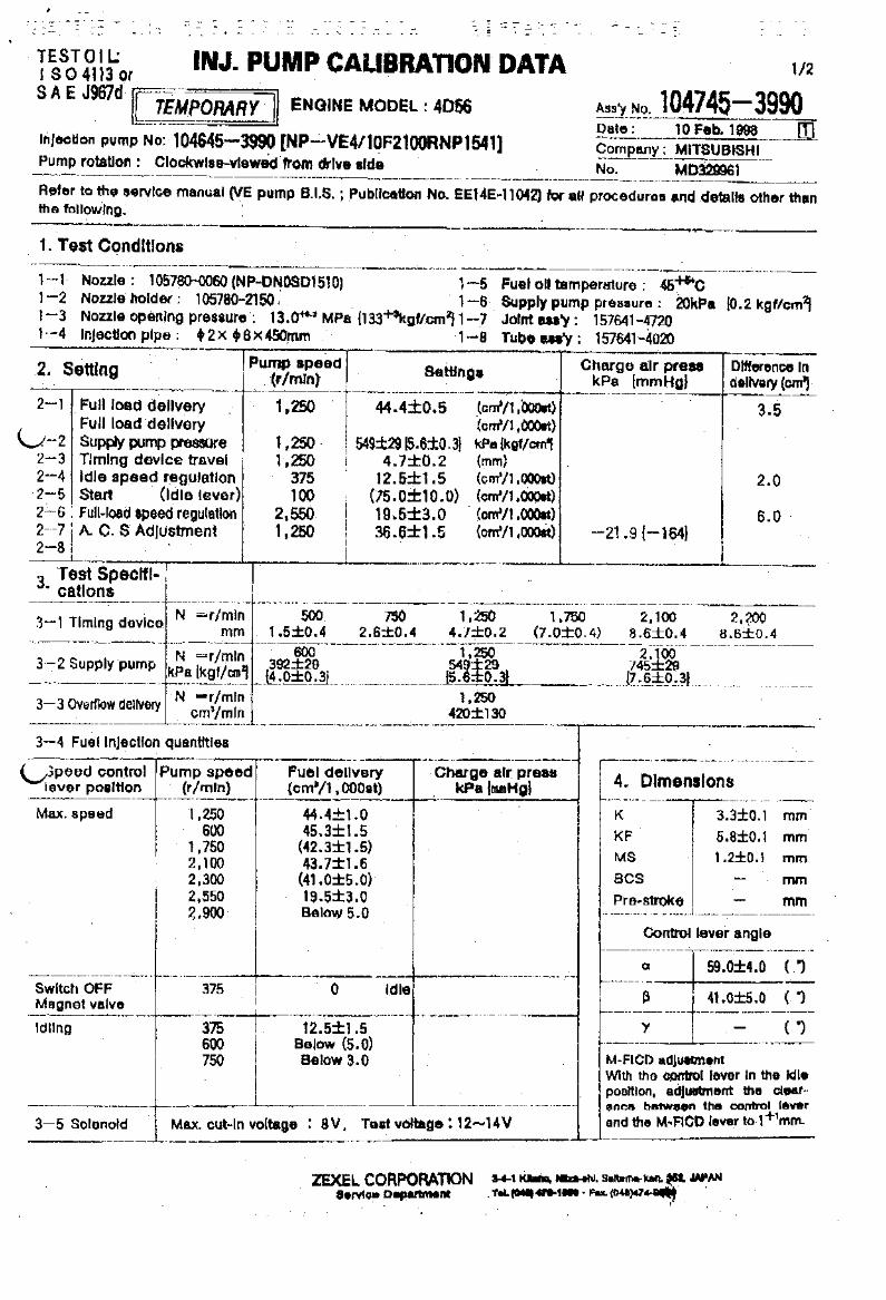
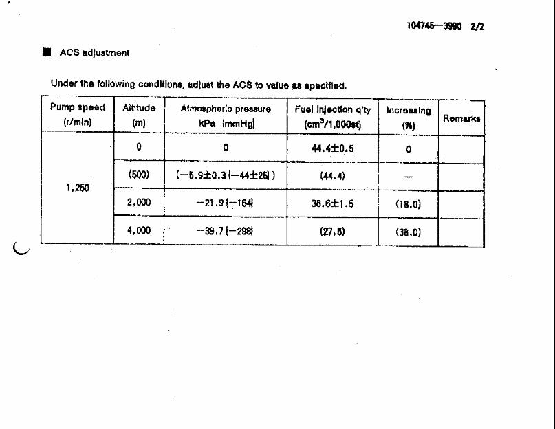

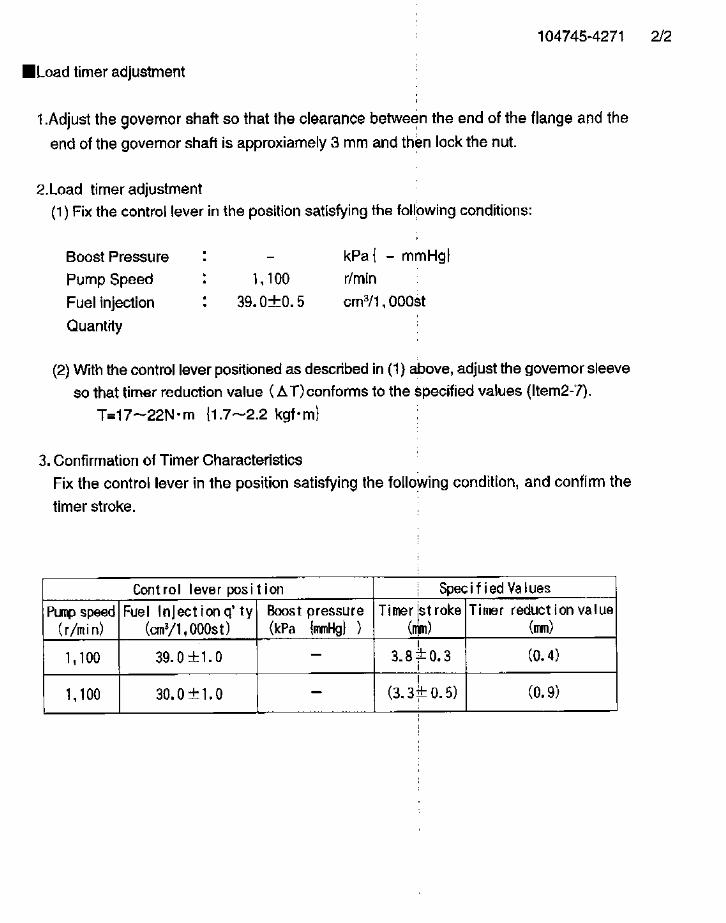


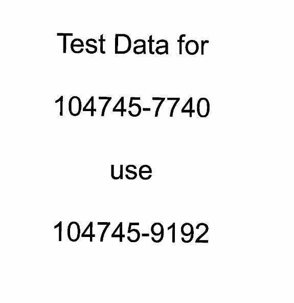
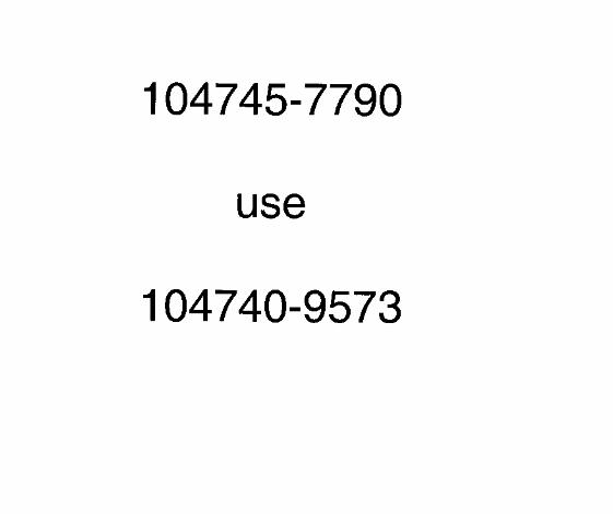

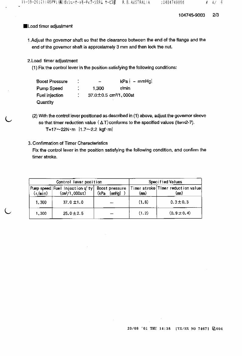
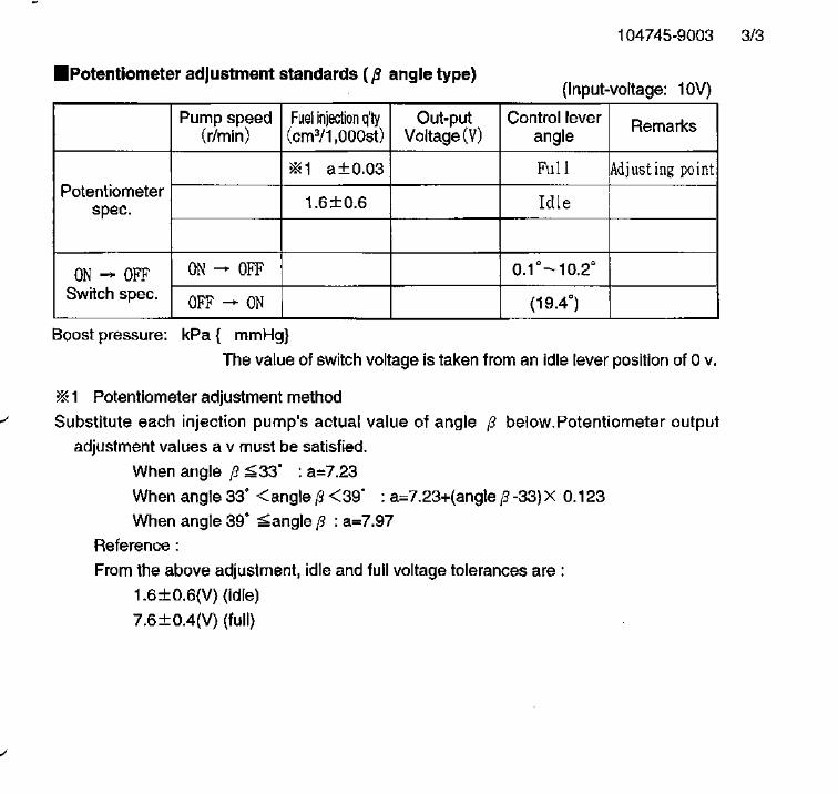

104745-9160 ZEXEL test values diesel fuel-injection equipment 26/06/03 09:56:56 Page 1
ZEXEL Ass'y No. 104745-9160
Bosch Ass'y No. 9 460 613 020
Bosch Typecode
Engine Type TD27-T
Manufacturer NISSAN DIESEL
Edition date 01/11/02
1 Adjustment conditions
CAT Designation Unit Set value min. max. Actual values OT
Test oil ISO4113orSAEJ967d
...
P Test Oil Temperature degC 45 45 50
Nozzle 105780-0060
Bosch type code NP-DN0SD1510
Nozzle holder 105780-2150
P Opening Pressure MPa 13 13 13.3
P Opening Pressure kgf/cm2 133 133 136
Iinjection Pipe 157805-7320
P Iinjection Pipe mm 2-6-450
Inside diameter - outside diameter - length (mm)
Joint Assembly 157641-4720
Tube Assembly 157641-4020
P Transfer pump pressure kPa 20 20 20
P Transfer pump pressure kgf/cm2 0.2 0.2 0.2
Direction of rotation (viewed from drive side) R
Right
2 Adjustment specification
2.1 Full load delivery
CAT Designation Unit Set value min. max. Actual values OT
P Pump speed r/min 850 850 850
P Boost pressure kPa 32 30.7 33.3
P Boost pressure mmHg 240 230 250
S Average injection quantity mm3/st. 56 55.5 56.5
P Basic *
P Oil temperature degC 50 48 52
Remarks
BCS
CAT Designation Unit Set value min. max. Actual values OT
P Pump speed r/min 1100 1100 1100
P Boost pressure kPa 66.7 65.4 68
P Boost pressure mmHg 500 490 510
S Average injection quantity mm3/st. 66.2 65.7 66.7
S Differnce in delivery mm3/st. 5 5
P Basic *
P Oil temperature degC 50 48 52
Remarks
Full
CAT Designation Unit Set value min. max. Actual values OT
P Pump speed r/min 500 500 500
P Boost pressure kPa 0 0 0
S = Setting value, C = Check value)OT = Outside Tolerance (X is set)
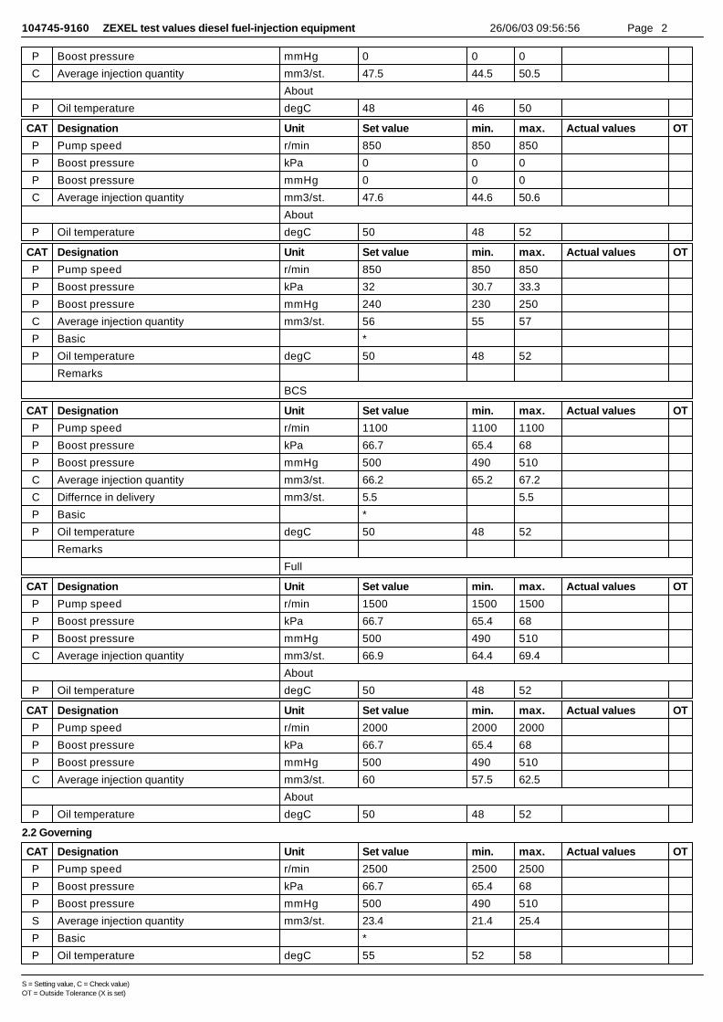
104745-9160 ZEXEL test values diesel fuel-injection equipment 26/06/03 09:56:56 Page 2
P Boost pressure mmHg 0 0 0
C Average injection quantity mm3/st. 47.5 44.5 50.5
About
P Oil temperature degC 48 46 50
CAT Designation Unit Set value min. max. Actual values OT
P Pump speed r/min 850 850 850
P Boost pressure kPa 0 0 0
P Boost pressure mmHg 0 0 0
C Average injection quantity mm3/st. 47.6 44.6 50.6
About
P Oil temperature degC 50 48 52
CAT Designation Unit Set value min. max. Actual values OT
P Pump speed r/min 850 850 850
P Boost pressure kPa 32 30.7 33.3
P Boost pressure mmHg 240 230 250
C Average injection quantity mm3/st. 56 55 57
P Basic *
P Oil temperature degC 50 48 52
Remarks
BCS
CAT Designation Unit Set value min. max. Actual values OT
P Pump speed r/min 1100 1100 1100
P Boost pressure kPa 66.7 65.4 68
P Boost pressure mmHg 500 490 510
C Average injection quantity mm3/st. 66.2 65.2 67.2
C Differnce in delivery mm3/st. 5.5 5.5
P Basic *
P Oil temperature degC 50 48 52
Remarks
Full
CAT Designation Unit Set value min. max. Actual values OT
P Pump speed r/min 1500 1500 1500
P Boost pressure kPa 66.7 65.4 68
P Boost pressure mmHg 500 490 510
C Average injection quantity mm3/st. 66.9 64.4 69.4
About
P Oil temperature degC 50 48 52
CAT Designation Unit Set value min. max. Actual values OT
P Pump speed r/min 2000 2000 2000
P Boost pressure kPa 66.7 65.4 68
P Boost pressure mmHg 500 490 510
C Average injection quantity mm3/st. 60 57.5 62.5
About
P Oil temperature degC 50 48 52
2.2 Governing
CAT Designation Unit Set value min. max. Actual values OT
P Pump speed r/min 2500 2500 2500
P Boost pressure kPa 66.7 65.4 68
P Boost pressure mmHg 500 490 510
S Average injection quantity mm3/st. 23.4 21.4 25.4
P Basic *
P Oil temperature degC 55 52 58
S = Setting value, C = Check value)OT = Outside Tolerance (X is set)
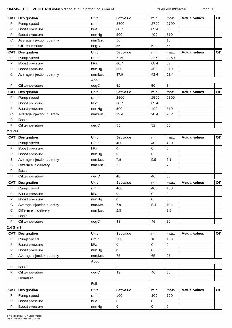
104745-9160 ZEXEL test values diesel fuel-injection equipment 26/06/03 09:56:56 Page 3
CAT Designation Unit Set value min. max. Actual values OT
P Pump speed r/min 2700 2700 2700
P Boost pressure kPa 66.7 65.4 68
P Boost pressure mmHg 500 490 510
C Average injection quantity mm3/st. 10 10
P Oil temperature degC 55 52 58
CAT Designation Unit Set value min. max. Actual values OT
P Pump speed r/min 2250 2250 2250
P Boost pressure kPa 66.7 65.4 68
P Boost pressure mmHg 500 490 510
C Average injection quantity mm3/st. 47.9 43.4 52.4
About
P Oil temperature degC 52 50 54
CAT Designation Unit Set value min. max. Actual values OT
P Pump speed r/min 2500 2500 2500
P Boost pressure kPa 66.7 65.4 68
P Boost pressure mmHg 500 490 510
C Average injection quantity mm3/st. 23.4 20.4 26.4
P Basic *
P Oil temperature degC 55 52 58
2.3 Idle
CAT Designation Unit Set value min. max. Actual values OT
P Pump speed r/min 400 400 400
P Boost pressure kPa 0 0 0
P Boost pressure mmHg 0 0 0
S Average injection quantity mm3/st. 7.9 5.9 9.9
S Differnce in delivery mm3/st. 2 2
P Basic *
P Oil temperature degC 48 46 50
CAT Designation Unit Set value min. max. Actual values OT
P Pump speed r/min 400 400 400
P Boost pressure kPa 0 0 0
P Boost pressure mmHg 0 0 0
C Average injection quantity mm3/st. 7.9 5.4 10.4
C Differnce in delivery mm3/st. 2.5 2.5
P Basic *
P Oil temperature degC 48 46 50
2.4 Start
CAT Designation Unit Set value min. max. Actual values OT
P Pump speed r/min 100 100 100
P Boost pressure kPa 0 0 0
P Boost pressure mmHg 0 0 0
S Average injection quantity mm3/st. 75 65 95
About
P Basic *
P Oil temperature degC 48 46 50
Remarks
Full
CAT Designation Unit Set value min. max. Actual values OT
P Pump speed r/min 100 100 100
P Boost pressure kPa 0 0 0
P Boost pressure mmHg 0 0 0
S = Setting value, C = Check value)OT = Outside Tolerance (X is set)
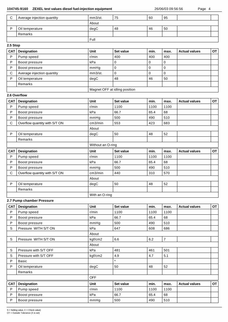
104745-9160 ZEXEL test values diesel fuel-injection equipment 26/06/03 09:56:56 Page 4
C Average injection quantity mm3/st. 75 60 95
About
P Oil temperature degC 48 46 50
Remarks
Full
2.5 Stop
CAT Designation Unit Set value min. max. Actual values OT
P Pump speed r/min 400 400 400
P Boost pressure kPa 0 0 0
P Boost pressure mmHg 0 0 0
C Average injection quantity mm3/st. 0 0 0
P Oil temperature degC 48 46 50
Remarks
Magnet OFF at idling position
2.6 Overflow
CAT Designation Unit Set value min. max. Actual values OT
P Pump speed r/min 1100 1100 1100
P Boost pressure kPa 66.7 65.4 68
P Boost pressure mmHg 500 490 510
C Overflow quantity with S/T ON cm3/min 553 423 683
About
P Oil temperature degC 50 48 52
Remarks
Without an O-ring
CAT Designation Unit Set value min. max. Actual values OT
P Pump speed r/min 1100 1100 1100
P Boost pressure kPa 66.7 65.4 68
P Boost pressure mmHg 500 490 510
C Overflow quantity with S/T ON cm3/min 440 310 570
About
P Oil temperature degC 50 48 52
Remarks
With an O-ring
2.7 Pump chamber Pressure
CAT Designation Unit Set value min. max. Actual values OT
P Pump speed r/min 1100 1100 1100
P Boost pressure kPa 66.7 65.4 68
P Boost pressure mmHg 500 490 510
S Pressure WITH S/T ON kPa 647 608 686
About
S Pressure WITH S/T ON kgf/cm2 6.6 6.2 7
About
S Pressure with S/T OFF kPa 481 461 501
S Pressure with S/T OFF kgf/cm2 4.9 4.7 5.1
P Basic *
P Oil temperature degC 50 48 52
Remarks
OFF
CAT Designation Unit Set value min. max. Actual values OT
P Pump speed r/min 1100 1100 1100
P Boost pressure kPa 66.7 65.4 68
P Boost pressure mmHg 500 490 510
S = Setting value, C = Check value)OT = Outside Tolerance (X is set)
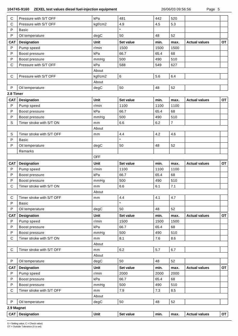
104745-9160 ZEXEL test values diesel fuel-injection equipment 26/06/03 09:56:56 Page 5
C Pressure with S/T OFF kPa 481 442 520
C Pressure with S/T OFF kgf/cm2 4.9 4.5 5.3
P Basic *
P Oil temperature degC 50 48 52
CAT Designation Unit Set value min. max. Actual values OT
P Pump speed r/min 1500 1500 1500
P Boost pressure kPa 66.7 65.4 68
P Boost pressure mmHg 500 490 510
C Pressure with S/T OFF kPa 588 549 627
About
C Pressure with S/T OFF kgf/cm2 6 5.6 6.4
About
P Oil temperature degC 50 48 52
2.8 Timer
CAT Designation Unit Set value min. max. Actual values OT
P Pump speed r/min 1100 1100 1100
P Boost pressure kPa 66.7 65.4 68
P Boost pressure mmHg 500 490 510
S Timer stroke with S/T ON mm 6.6 6.2 7
About
S Timer stroke with S/T OFF mm 4.4 4.2 4.6
P Basic *
P Oil temperature degC 50 48 52
Remarks
OFF
CAT Designation Unit Set value min. max. Actual values OT
P Pump speed r/min 1100 1100 1100
P Boost pressure kPa 66.7 65.4 68
P Boost pressure mmHg 500 490 510
C Timer stroke with S/T ON mm 6.6 6.1 7.1
About
C Timer stroke with S/T OFF mm 4.4 4.1 4.7
P Basic *
P Oil temperature degC 50 48 52
CAT Designation Unit Set value min. max. Actual values OT
P Pump speed r/min 1500 1500 1500
P Boost pressure kPa 66.7 65.4 68
P Boost pressure mmHg 500 490 510
C Timer stroke with S/T ON mm 8.1 7.6 8.6
About
C Timer stroke with S/T OFF mm 6.2 5.7 6.7
About
P Oil temperature degC 50 48 52
CAT Designation Unit Set value min. max. Actual values OT
P Pump speed r/min 2000 2000 2000
P Boost pressure kPa 66.7 65.4 68
P Boost pressure mmHg 500 490 510
C Timer stroke with S/T OFF mm 7.9 7.3 8.5
About
P Oil temperature degC 50 48 52
2.9 Magnet
CAT Designation Unit Set value min. max. Actual values OT
S = Setting value, C = Check value)OT = Outside Tolerance (X is set)

104745-9160 ZEXEL test values diesel fuel-injection equipment 26/06/03 09:56:56 Page 6
C MAX applied voltage V 8 8 8
P Test voltage V 13 12 14
2.10 Compensator
2.10.1 Load-Timer adjustment
CAT Designation Unit Set value min. max. Actual values OT
P Pump speed r/min 1100 1100 1100
P Boost pressure kPa 66.7 65.4 68
P Boost pressure mmHg 500 490 510
S Average injection quantity mm3/st. 45 44.5 45.5
S Timer stroke TA mm 3.8 3.6 4
S Timer stroke variation dT mm 0.6 0.6 0.6
About
P Basic *
P Oil temperature degC 50 48 52
CAT Designation Unit Set value min. max. Actual values OT
P Pump speed r/min 1100 1100 1100
P Boost pressure kPa 66.7 65.4 68
P Boost pressure mmHg 500 490 510
C Average injection quantity mm3/st. 45 44 46
C Timer stroke TA mm 3.8 3.5 4.1
P Basic *
P Oil temperature degC 50 48 52
CAT Designation Unit Set value min. max. Actual values OT
P Pump speed r/min 1100 1100 1100
P Boost pressure kPa 66.7 65.4 68
P Boost pressure mmHg 500 490 510
C Average injection quantity mm3/st. 34 31.5 36.5
C Timer stroke TA mm 3 2.5 3.5
About
P Oil temperature degC 50 48 52
2.11 Additional device adjustment
2.11.1 Additional device 1
Name POTENTIOMETER ADJUSTMENT
N1=850r/minQ1=22.9+-1.0cm3/1,000stV1=3.72+-0.03VV2=(2.0+-0.43)VV3=(7.86+-0.58)VC3=(2.5)degC4=(17.0)deg
S = Setting value, C = Check value)OT = Outside Tolerance (X is set)
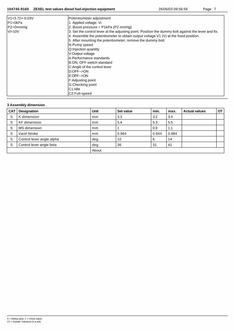
104745-9160 ZEXEL test values diesel fuel-injection equipment 26/06/03 09:56:56 Page 7
V1=3.72+-0.03VP1=0kPaP2=0mmHgVi=10V
Potentiometer adjustment1. Applied voltage: Vi2. Boost pressure = P1kPa {P2 mmHg}3. Set the control lever at the adjusting point. Position the dummy bolt against the lever and fix.4. Assemble the potentiometer to obtain output voltage V1 (V) at the fixed position.5. After mounting the potentiometer, remove the dummy bolt.N:Pump speedQ:Injection quantityV:Output voltageA:Performance standardsB:ON, OFF switch standardC:Angle of the control leverD:OFF-->ONE:OFF-->ONF:Adjusting pointG:Checking pointC1:IdleC2:Full-speed
3 Assembly dimension
CAT Designation Unit Set value min. max. Actual values OT
S K dimension mm 3.3 3.2 3.4
S KF dimension mm 5.4 5.3 5.5
S MS dimension mm 1 0.9 1.1
S Varid Stroke mm 0.964 0.944 0.984
S Control lever angle alpha deg. 10 6 14
S Control lever angle beta deg. 36 31 41
About
S = Setting value, C = Check value)OT = Outside Tolerance (X is set)
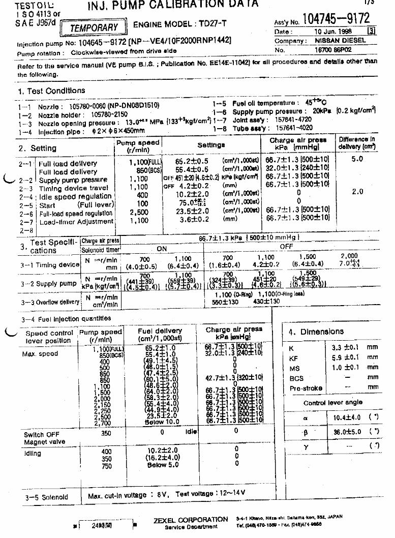
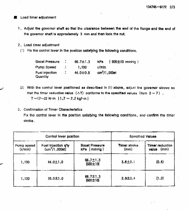
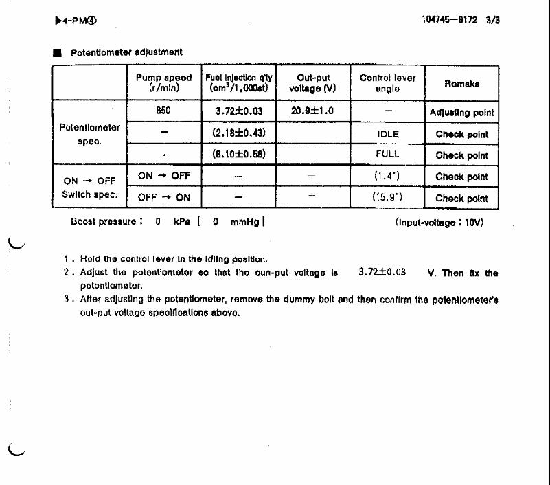
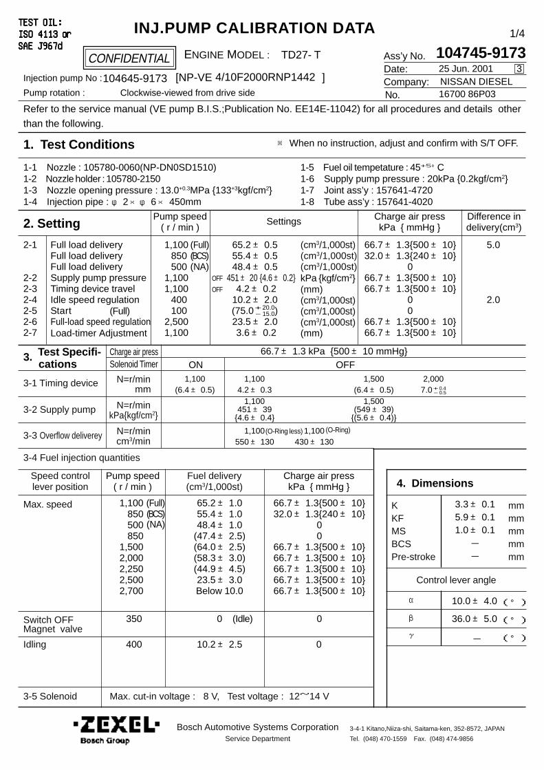
Ass’y No.Date:Company:No.
Refer to the service manual (VE pump B.I.S.;Publication No. EE14E-11042) for all procedures and details other
than the following.
1. Test Conditions
2. Setting
4. Dimensions
CONFIDENTIAL
INJ.PUMP CALIBRATION DATATEST OIL:TEST OIL:TEST OIL:TEST OIL:TEST OIL:ISO 4113ISO 4113ISO 4113ISO 4113ISO 4113 or or or or orSAE J967dSAE J967dSAE J967dSAE J967dSAE J967d
ENGINE MODEL :
Injection pump No : [NP-VE ]Pump rotation : Clockwise-viewed from drive side
Pump speed( r / min )
Settings Charge air presskPa { mmHg }
Difference indelivery(cm3)
Full load delivery
Supply pump pressureTiming device travelIdle speed regulationStartFull-load speed regulation
2-1
2-22-32-42-52-62-7
(cm3/1,000st)
kPa {kgf/cm2}(mm)(cm3/1,000st)(cm3/1,000st)(cm3/1,000st)
Pump speed( r / min )
Charge air presskPa { mmHg }
3. Test Specifi- cations
3-1 Timing device
3-2 Supply pump
3-3 Overflow deliverey
N=r/min mm
N=r/minkPa{kgf/cm2}
N=r/mincm3/min
3-4 Fuel injection quantities
Speed controllever position
Fuel delivery(cm3/1,000st)
Max. speed
Switch OFFMagnet valve
Idling
3-5 Solenoid
KKFMSBCSPre-stroke
mmmmmmmmmm
α
β
γ
(°)
(°)
(°)-
Control lever angle
Bosch Automotive Systems CorporationService Department
3-4-1 Kitano,Niiza-shi, Saitama-ken, 352-8572, JAPAN
Tel. (048) 470-1559 Fax. (048) 474-9856
1,100 850 5001,1001,100 400 1002,5001,100
1,100 1,100 1,500 2,000(6.4± 0.5) 4.2± 0.3 (6.4± 0.5) 7.0+ 0.4 - 0.5
1,100 1,500451± 39 (549± 39)
{4.6± 0.4} {(5.6± 0.4)}
1,100 1,100550± 130 430± 130
66.7± 1.3 kPa {500± 10 mmHg}
25 Jun. 2001
104745-91733
NISSAN DIESEL16700 86P03
4/10F2000RNP1442104645-9173
TD27- T
65.2± 0.555.4± 0.548.4± 0.5
451± 20 {4.6± 0.2} 4.2± 0.210.2± 2.0(75.0+ 20.0 - 15.0)23.5± 2.0 3.6± 0.2
66.7± 1.3{500± 10}32.0± 1.3{240± 10}
066.7± 1.3{500± 10}66.7± 1.3{500± 10}
00
66.7± 1.3{500± 10}66.7± 1.3{500± 10}
5.0
2.0
1,100 850 500 8501,5002,0002,2502,5002,700
1/4
65.2± 1.055.4± 1.048.4± 1.0
(47.4± 2.5)(64.0± 2.5)(58.3± 3.0)(44.9± 4.5)23.5± 3.0Below 10.0
66.7± 1.3{500± 10}32.0± 1.3{240± 10}
00
66.7± 1.3{500± 10}66.7± 1.3{500± 10}66.7± 1.3{500± 10}66.7± 1.3{500± 10}66.7± 1.3{500± 10}
350 0 0
400 10.2± 2.5 0
3.3± 0.15.9± 0.11.0± 0.1--
10.0± 4.0
36.0± 5.0
Max. cut-in voltage : 8 V, Test voltage : 12~14 V
OFF
OFF
Load-timer Adjustment (mm)
ON OFFCharge air pressSolenoid Timer
Full load delivery
(Full)(BCS)(NA)
(Full)(BCS)(NA)
(cm3/1,000st)Full load delivery (cm3/1,000st)
1-1 Nozzle : 105780-0060(NP-DN0SD1510)1-2 Nozzle holder : 105780-21501-3 Nozzle opening pressure : 13.0+0.3MPa {133+3kgf/cm2}1-4 Injection pipe : φ 2×φ 6× 450mm
1-5 Fuel oil tempetature : 45+5°C1-6 Supply pump pressure : 20kPa {0.2kgf/cm2}1-7 Joint ass’y : 157641-47201-8 Tube ass’y : 157641-4020
(Idle)
(Full)
(O-Ring)
※ When no instruction, adjust and confirm with S/T OFF.
(O-Ring less)
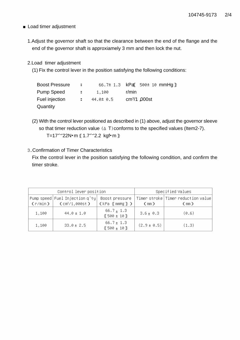
104745-9173 2/4
■Load timer adjustment
1.Adjust the governor shaft so that the clearance between the end of the flange and the
end of the governor shaft is approxiamely 3 mm and then lock the nut.
2.Load timer adjustment
(1) Fix the control lever in the position satisfying the following conditions:
Boost Pressure : 66.7±1.3 kPa{ 500±10 mmHg} Pump Speed : 1,100 r/min
Fuel injection : 44.0±0.5 cm3/1,000st
Quantity
(2) With the control lever positioned as described in (1) above, adjust the governor sleeve
so that timer reduction value (ΔT)conforms to the specified values (Item2-7).
T=17~22N・m {1.7~2.2 kgf・m}
3.Confirmation of Timer Characteristics
Fix the control lever in the position satisfying the following condition, and confirm the
timer stroke.
Control lever position Specified ValuesPump speed(r/min)
Fuel Injection q'ty(cm3/1,000st)
Boost pressure(kPa {mmHg})
Timer stroke(mm)
Timer reduction value(mm)
1,100 44.0 1.0 66.7 1.3{500 10} 3.6 0.3 (0.6)
1,100 33.0 2.5 66.7 1.3{500 10} (2.9 0.5) (1.3)±
±
±
±±±
±±

104745-9173 3/4
■Boost compensator adjustment BCS ①①①①①
1. Adjust full load injection quantities to value as described in item 2-1.
2. Adjust BCS's injection quantities to value as described in item 2-1 .3. Confirm the NA's injection quantities to value as described in item 2-1.
4. If the NA above is not specified, loosen nut 53 and adjust screw 50 so that NA is as
specified and thed fix nut 53 .
<Caution>
Do not tighten or loosen screw 50 more than 1 turn.
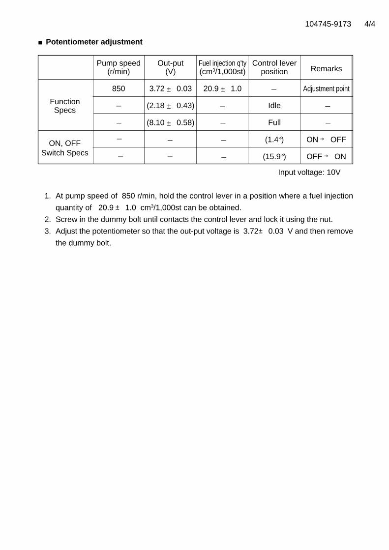
104745-9173 4/4
■Potentiometer adjustment
Pump speed Out-put Fuel injection q'ty Control leverRemarks(r/min) (V) (cm3/1,000st) position
850 3.72 ± 0.03 20.9 ± 1.0 Adjustment point
Function (2.18 ± 0.43) IdleSpecs
(8.10 ± 0.58) Full
ON, OFF (1.4°) ON → OFF
Switch Specs (15.9°) OFF → ON
Input voltage: 10V
1. At pump speed of 850 r/min, hold the control lever in a position where a fuel injection
quantity of 20.9± 1.0 cm3/1,000st can be obtained.
2. Screw in the dummy bolt until contacts the control lever and lock it using the nut.
3. Adjust the potentiometer so that the out-put voltage is 3.72± 0.03 V and then remove
the dummy bolt.
- -
-
-
-
-
-
-
-
-
-
-
-

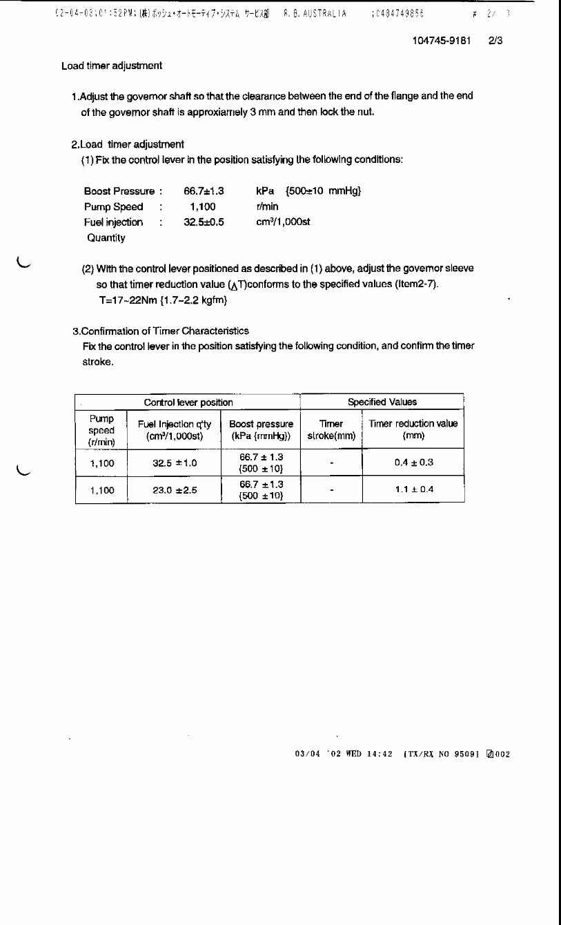
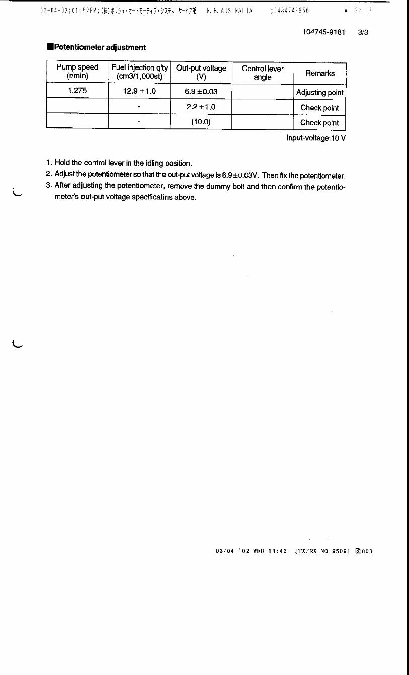

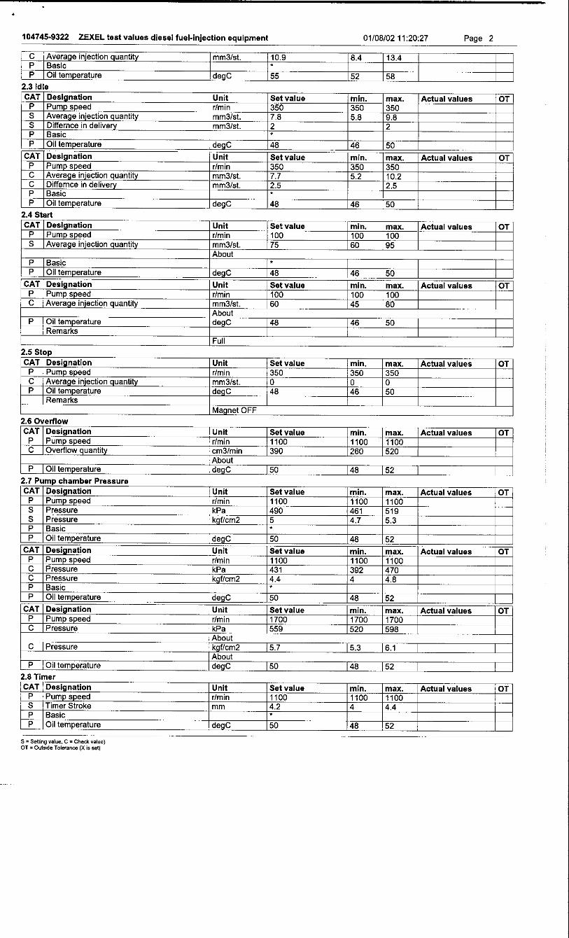

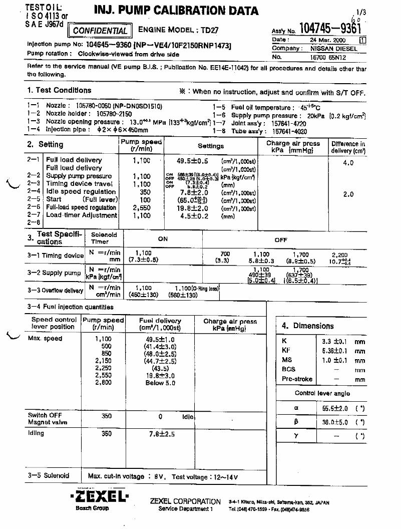

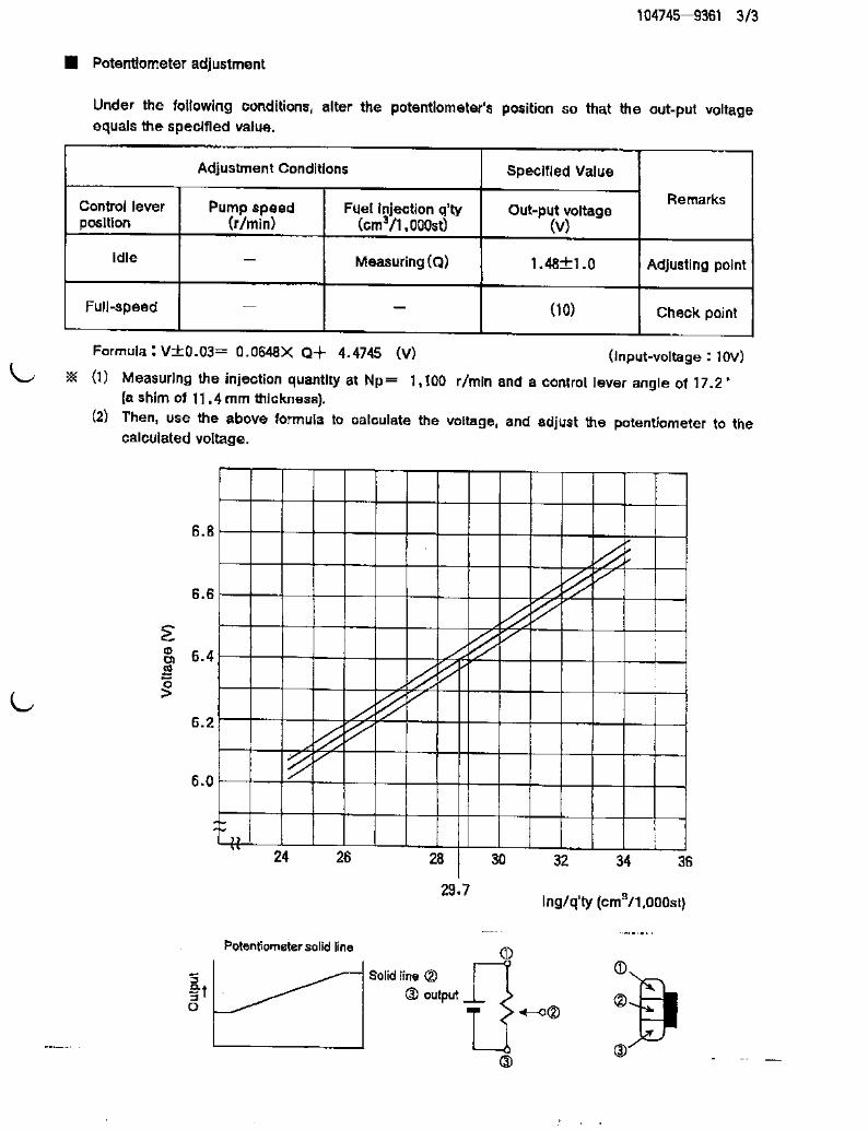
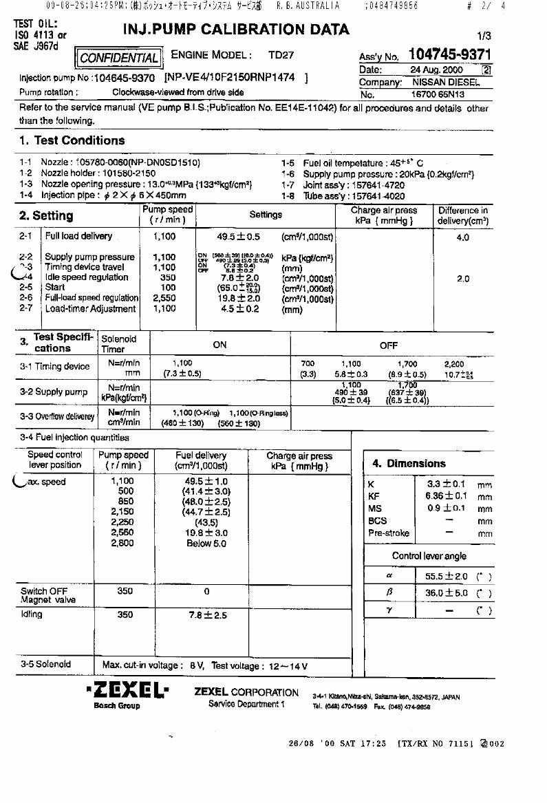
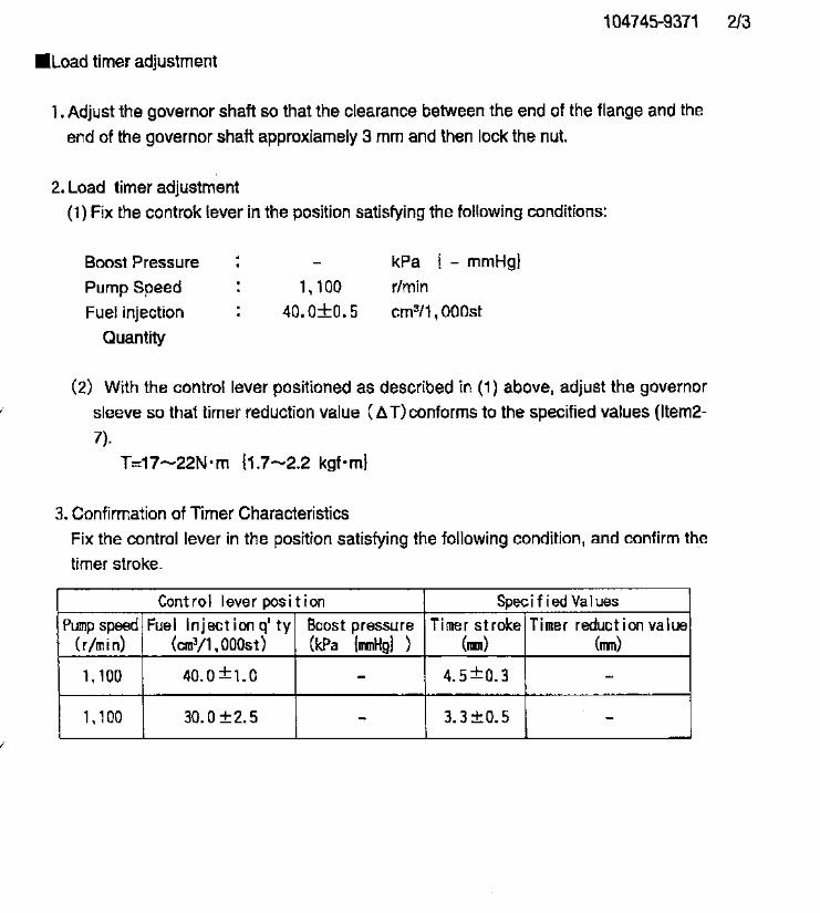

104745-9570
Doowon
Refer to Kia
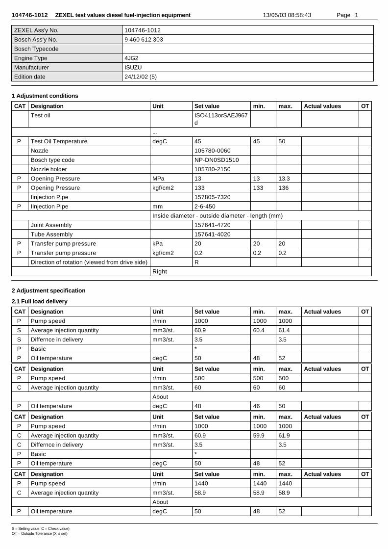
104746-1012 ZEXEL test values diesel fuel-injection equipment 13/05/03 08:58:43 Page 1
ZEXEL Ass'y No. 104746-1012
Bosch Ass'y No. 9 460 612 303
Bosch Typecode
Engine Type 4JG2
Manufacturer ISUZU
Edition date 24/12/02 (5)
1 Adjustment conditions
CAT Designation Unit Set value min. max. Actual values OT
Test oil ISO4113orSAEJ967d
...
P Test Oil Temperature degC 45 45 50
Nozzle 105780-0060
Bosch type code NP-DN0SD1510
Nozzle holder 105780-2150
P Opening Pressure MPa 13 13 13.3
P Opening Pressure kgf/cm2 133 133 136
Iinjection Pipe 157805-7320
P Iinjection Pipe mm 2-6-450
Inside diameter - outside diameter - length (mm)
Joint Assembly 157641-4720
Tube Assembly 157641-4020
P Transfer pump pressure kPa 20 20 20
P Transfer pump pressure kgf/cm2 0.2 0.2 0.2
Direction of rotation (viewed from drive side) R
Right
2 Adjustment specification
2.1 Full load delivery
CAT Designation Unit Set value min. max. Actual values OT
P Pump speed r/min 1000 1000 1000
S Average injection quantity mm3/st. 60.9 60.4 61.4
S Differnce in delivery mm3/st. 3.5 3.5
P Basic *
P Oil temperature degC 50 48 52
CAT Designation Unit Set value min. max. Actual values OT
P Pump speed r/min 500 500 500
C Average injection quantity mm3/st. 60 60 60
About
P Oil temperature degC 48 46 50
CAT Designation Unit Set value min. max. Actual values OT
P Pump speed r/min 1000 1000 1000
C Average injection quantity mm3/st. 60.9 59.9 61.9
C Differnce in delivery mm3/st. 3.5 3.5
P Basic *
P Oil temperature degC 50 48 52
CAT Designation Unit Set value min. max. Actual values OT
P Pump speed r/min 1440 1440 1440
C Average injection quantity mm3/st. 58.9 58.9 58.9
About
P Oil temperature degC 50 48 52
S = Setting value, C = Check value)OT = Outside Tolerance (X is set)
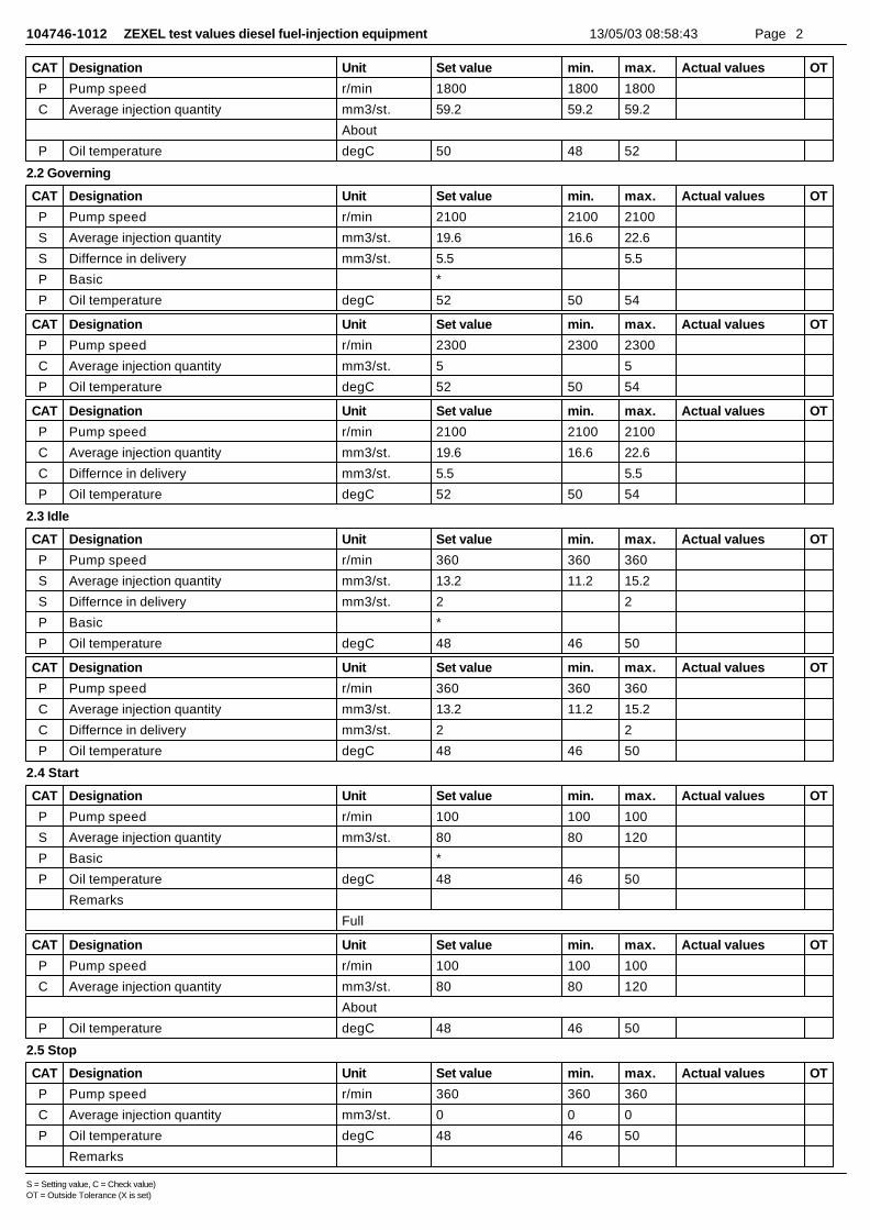
104746-1012 ZEXEL test values diesel fuel-injection equipment 13/05/03 08:58:43 Page 2
CAT Designation Unit Set value min. max. Actual values OT
P Pump speed r/min 1800 1800 1800
C Average injection quantity mm3/st. 59.2 59.2 59.2
About
P Oil temperature degC 50 48 52
2.2 Governing
CAT Designation Unit Set value min. max. Actual values OT
P Pump speed r/min 2100 2100 2100
S Average injection quantity mm3/st. 19.6 16.6 22.6
S Differnce in delivery mm3/st. 5.5 5.5
P Basic *
P Oil temperature degC 52 50 54
CAT Designation Unit Set value min. max. Actual values OT
P Pump speed r/min 2300 2300 2300
C Average injection quantity mm3/st. 5 5
P Oil temperature degC 52 50 54
CAT Designation Unit Set value min. max. Actual values OT
P Pump speed r/min 2100 2100 2100
C Average injection quantity mm3/st. 19.6 16.6 22.6
C Differnce in delivery mm3/st. 5.5 5.5
P Oil temperature degC 52 50 54
2.3 Idle
CAT Designation Unit Set value min. max. Actual values OT
P Pump speed r/min 360 360 360
S Average injection quantity mm3/st. 13.2 11.2 15.2
S Differnce in delivery mm3/st. 2 2
P Basic *
P Oil temperature degC 48 46 50
CAT Designation Unit Set value min. max. Actual values OT
P Pump speed r/min 360 360 360
C Average injection quantity mm3/st. 13.2 11.2 15.2
C Differnce in delivery mm3/st. 2 2
P Oil temperature degC 48 46 50
2.4 Start
CAT Designation Unit Set value min. max. Actual values OT
P Pump speed r/min 100 100 100
S Average injection quantity mm3/st. 80 80 120
P Basic *
P Oil temperature degC 48 46 50
Remarks
Full
CAT Designation Unit Set value min. max. Actual values OT
P Pump speed r/min 100 100 100
C Average injection quantity mm3/st. 80 80 120
About
P Oil temperature degC 48 46 50
2.5 Stop
CAT Designation Unit Set value min. max. Actual values OT
P Pump speed r/min 360 360 360
C Average injection quantity mm3/st. 0 0 0
P Oil temperature degC 48 46 50
Remarks
S = Setting value, C = Check value)OT = Outside Tolerance (X is set)
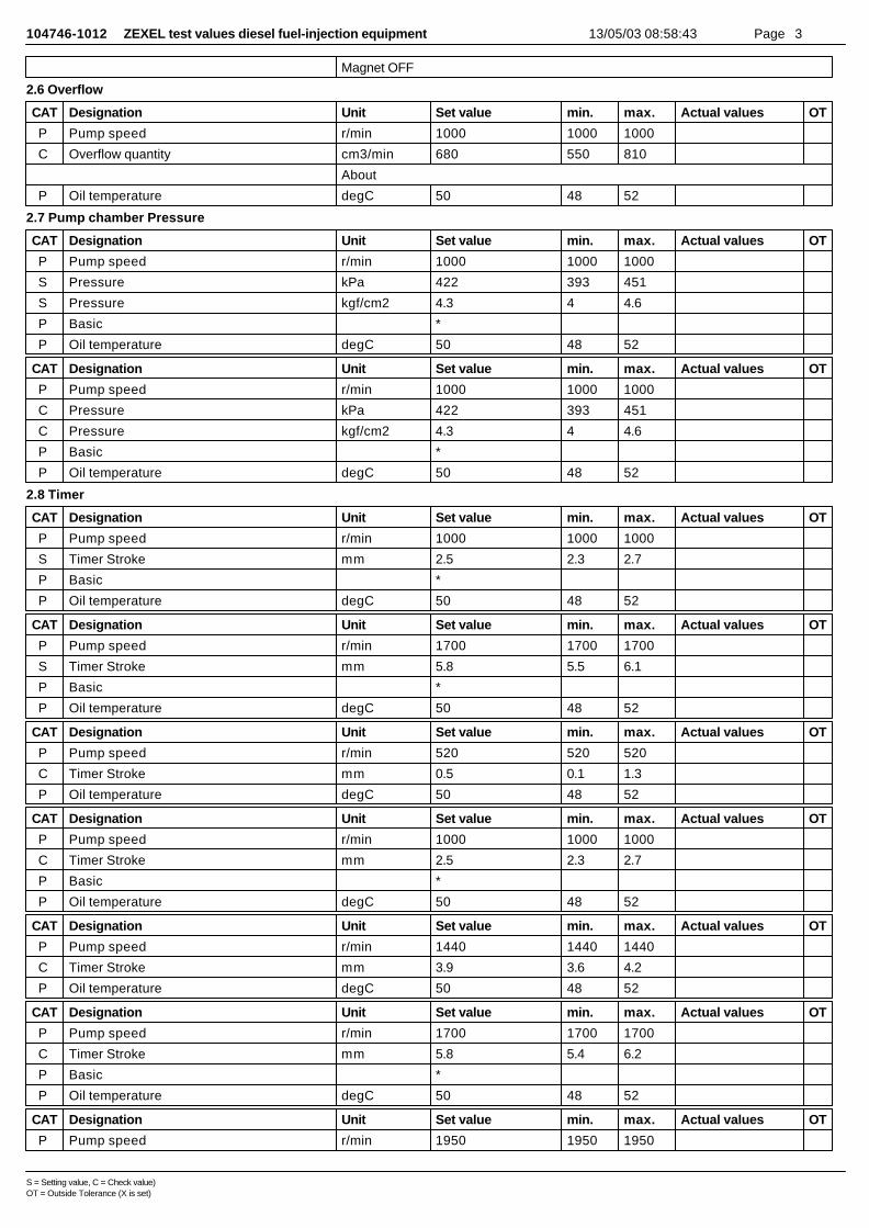
104746-1012 ZEXEL test values diesel fuel-injection equipment 13/05/03 08:58:43 Page 3
Magnet OFF
2.6 Overflow
CAT Designation Unit Set value min. max. Actual values OT
P Pump speed r/min 1000 1000 1000
C Overflow quantity cm3/min 680 550 810
About
P Oil temperature degC 50 48 52
2.7 Pump chamber Pressure
CAT Designation Unit Set value min. max. Actual values OT
P Pump speed r/min 1000 1000 1000
S Pressure kPa 422 393 451
S Pressure kgf/cm2 4.3 4 4.6
P Basic *
P Oil temperature degC 50 48 52
CAT Designation Unit Set value min. max. Actual values OT
P Pump speed r/min 1000 1000 1000
C Pressure kPa 422 393 451
C Pressure kgf/cm2 4.3 4 4.6
P Basic *
P Oil temperature degC 50 48 52
2.8 Timer
CAT Designation Unit Set value min. max. Actual values OT
P Pump speed r/min 1000 1000 1000
S Timer Stroke mm 2.5 2.3 2.7
P Basic *
P Oil temperature degC 50 48 52
CAT Designation Unit Set value min. max. Actual values OT
P Pump speed r/min 1700 1700 1700
S Timer Stroke mm 5.8 5.5 6.1
P Basic *
P Oil temperature degC 50 48 52
CAT Designation Unit Set value min. max. Actual values OT
P Pump speed r/min 520 520 520
C Timer Stroke mm 0.5 0.1 1.3
P Oil temperature degC 50 48 52
CAT Designation Unit Set value min. max. Actual values OT
P Pump speed r/min 1000 1000 1000
C Timer Stroke mm 2.5 2.3 2.7
P Basic *
P Oil temperature degC 50 48 52
CAT Designation Unit Set value min. max. Actual values OT
P Pump speed r/min 1440 1440 1440
C Timer Stroke mm 3.9 3.6 4.2
P Oil temperature degC 50 48 52
CAT Designation Unit Set value min. max. Actual values OT
P Pump speed r/min 1700 1700 1700
C Timer Stroke mm 5.8 5.4 6.2
P Basic *
P Oil temperature degC 50 48 52
CAT Designation Unit Set value min. max. Actual values OT
P Pump speed r/min 1950 1950 1950
S = Setting value, C = Check value)OT = Outside Tolerance (X is set)
104746-1012 ZEXEL test values diesel fuel-injection equipment 13/05/03 08:58:43 Page 4
C Timer Stroke mm 7.8 7.5 8.2
P Oil temperature degC 50 48 52
2.9 Magnet
CAT Designation Unit Set value min. max. Actual values OT
C MAX applied voltage V 8 8 8
P Test voltage V 13 12 14
2.10 Compensator
2.10.1 Load-Timer adjustment
CAT Designation Unit Set value min. max. Actual values OT
P Pump speed r/min 1000 1000 1000
S Average injection quantity mm3/st. 31.8 31.3 32.3
S Timer stroke TA mm 2.2 2.2 2.2
About
S Timer stroke variation dT mm 0.3 0.1 0.5
P Basic *
P Oil temperature degC 50 48 52
CAT Designation Unit Set value min. max. Actual values OT
P Pump speed r/min 1000 1000 1000
C Average injection quantity mm3/st. 31.8 30.8 32.8
C Timer stroke variation dT mm 0.3 -0.1 0.7
P Basic *
P Oil temperature degC 50 48 52
CAT Designation Unit Set value min. max. Actual values OT
P Pump speed r/min 1000 1000 1000
C Average injection quantity mm3/st. 16.7 15.7 17.7
C Timer stroke variation dT mm 1 0.4 1.6
P Oil temperature degC 50 48 52
2.11 Additional device adjustment
2.11.1 Additional device 1
Name W-CSD ADJUSTMENT
TA:TA=-0.0345t+2.59
Adjustment of the W-CSD1. Adjustment of the advance angle of the timer(1)Determine the timer advance angle using the graph.(2)(1) Adjust with the screw (A) so that the timer advance angle determined in the item (1) is obtained.Y:Timer stroke TAX:Temperature t(C): timer stroke TA(mm)
2.11.2 Additional device 2
S = Setting value, C = Check value)OT = Outside Tolerance (X is set)

104746-1012 ZEXEL test values diesel fuel-injection equipment 13/05/03 08:58:43 Page 5
Name V-FICD ADJUSTMENT
T=3.4~4.9N-m(0.35~0.50kgf-m)L1=1.40+-0.1mm
L1=1.40+-0.1mmL2=0.5mmL3=5mmP1=-53.3kPaP2=-400mmHg
Adjustment of the V-FICD1. Insert the shim of L1 between the control lever (A) and the idle adjusting screw (B).Adjust using the FICD adjusting screw (C) so that the actuator moves through its full stroke, thenfix using the nut (D).If adjustment with the FICD adjusting screw (C) is not possible, adjust by moving the actuator stroke with (E) and (F).2. Apply P1{P2} to the actuator. Confirm that it moves through its full stroke.After releasing, confirm that the clearance between the control lever (A) and the adjusting screw(C) is L2 or more.(G): exceeds L2 after releasing actuator(H): stroke L3
3 Assembly dimension
CAT Designation Unit Set value min. max. Actual values OT
S K dimension mm 3.3 3.2 3.4
S KF dimension mm 5.8 5.7 5.9
S MS dimension mm 0.7 0.6 0.8
S Pre-stroke mm 0.1 0.08 0.12
S Control lever angle alpha deg. 18 14 22
S Control lever angle beta deg. 31 26 36
S = Setting value, C = Check value)OT = Outside Tolerance (X is set)
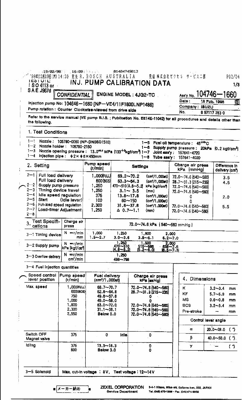
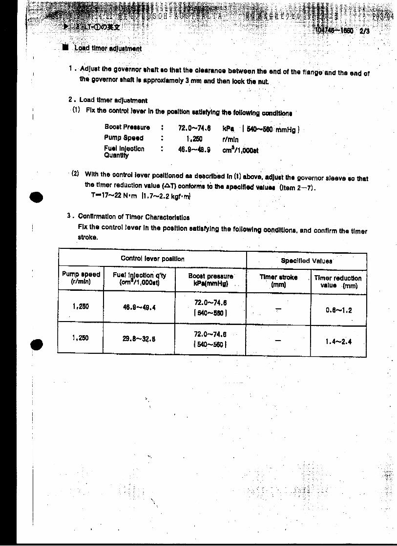
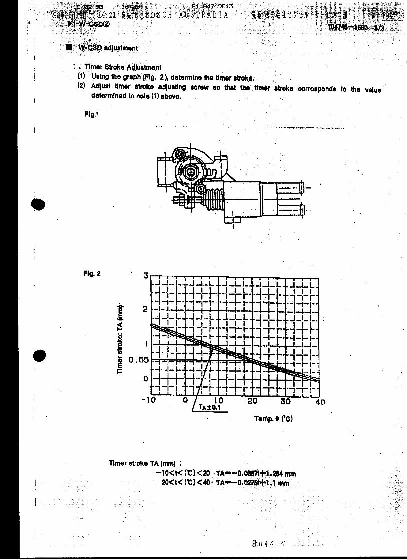
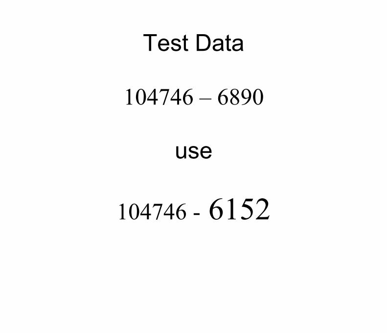
Test Data
104746 � 6890
use
104746 - 6152
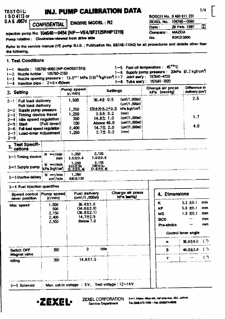
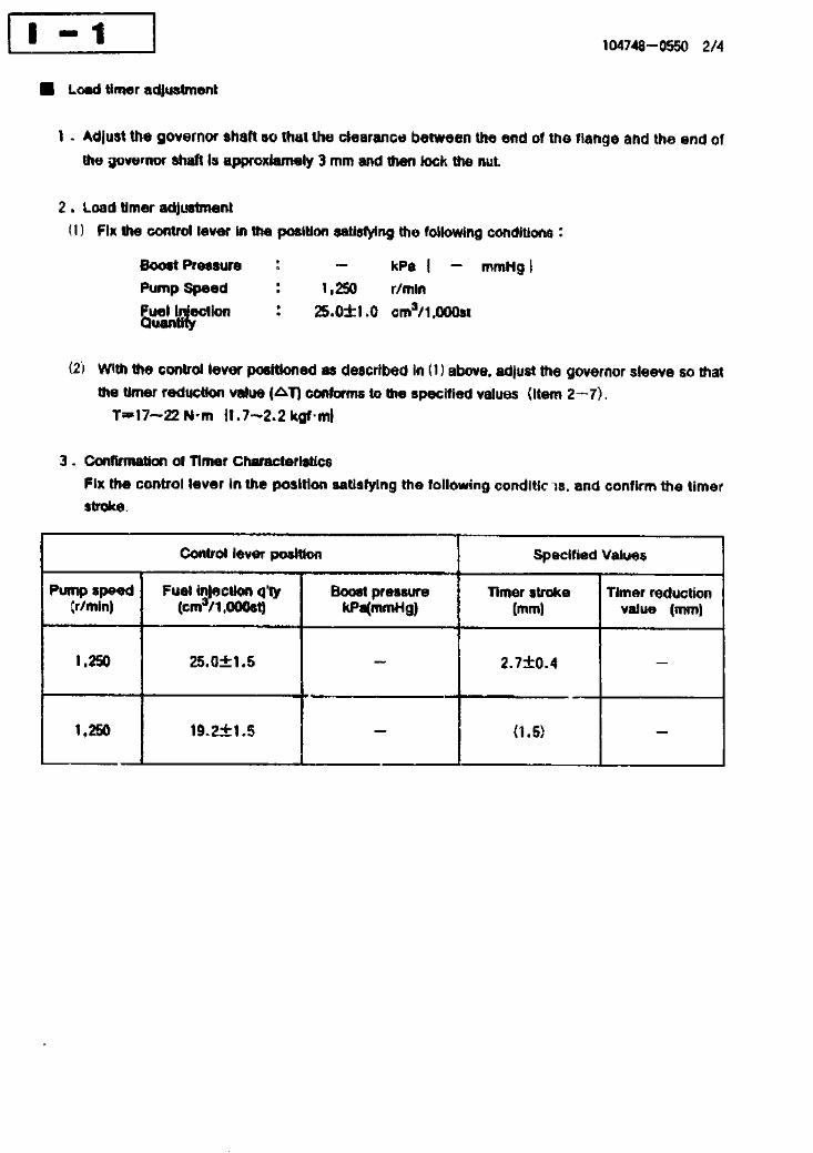

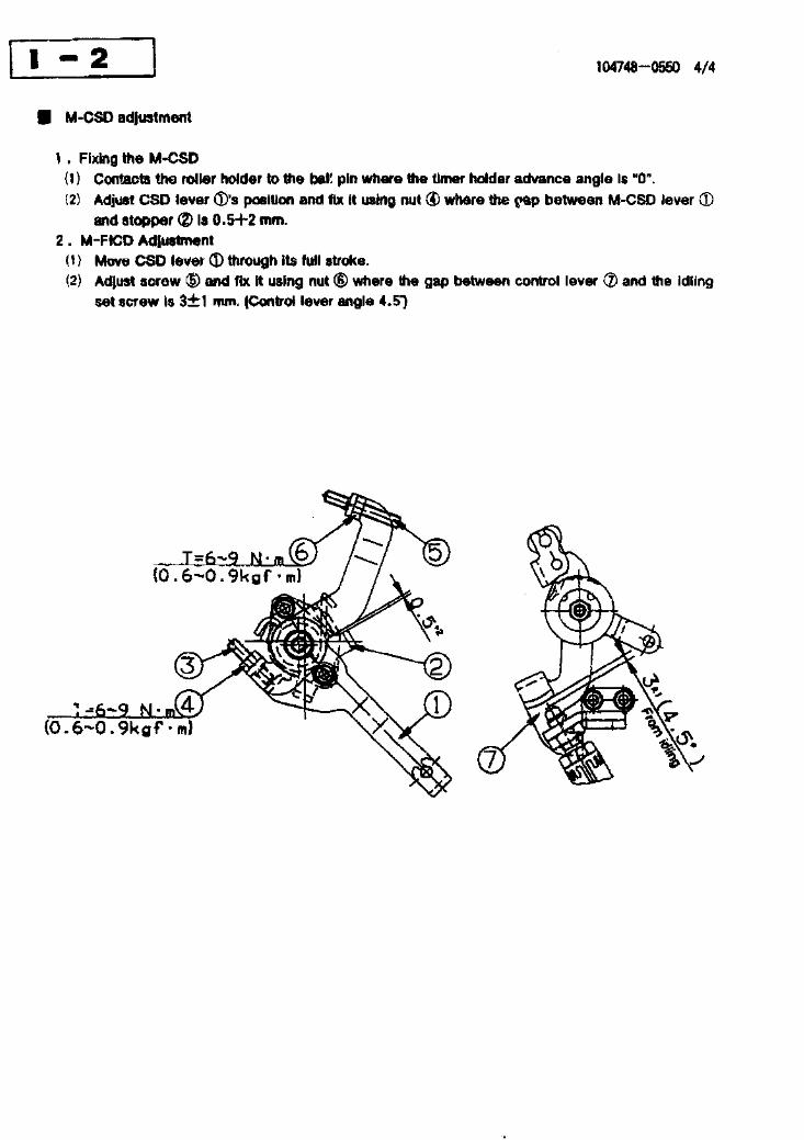
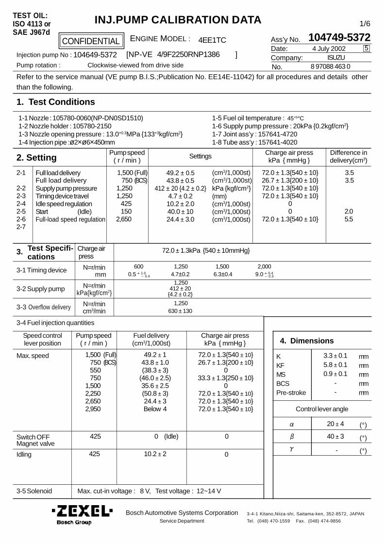
Ass’y No.Date:Company:No.
Refer to the service manual (VE pump B.I.S.;Publication No. EE14E-11042) for all procedures and details other
than the following.
1. Test Conditions
2. Setting
4. Dimensions
CONFIDENTIAL
INJ.PUMP CALIBRATION DATATEST OIL:ISO 4113 orSAE J967d
ENGINE MODEL :
Injection pump No : [NP-VE ]Pump rotation : Clockwise-viewed from drive side
Pump speed( r / min )
Settings Charge air presskPa { mmHg }
Difference indelivery(cm3)
Full load delivery
Supply pump pressureTiming device travelIdle speed regulationStartFull-load speed regulation
2-1
2-22-32-42-52-62-7
(cm3/1,000st)
kPa {kgf/cm2}(mm)(cm3/1,000st)(cm3/1,000st)(cm3/1,000st)
Pump speed( r / min )
Charge air presskPa { mmHg }
3. Test Specifi- cations
3-1 Timing device
3-2 Supply pump
3-3 Overflow delivery
N=r/min mm
N=r/minkPa{kgf/cm2}
N=r/mincm3/min
3-4 Fuel injection quantities
Speed controllever position
Fuel delivery(cm3/1,000st)
Max. speed
Switch OFFMagnet valve
Idling
3-5 Solenoid
KKFMSBCSPre-stroke
mmmmmmmmmm
(°)
(°)
(°)-
Control lever angle
Bosch Automotive Systems CorporationService Department
3-4-1 Kitano,Niiza-shi, Saitama-ken, 352-8572, JAPAN
Tel. (048) 470-1559 Fax. (048) 474-9856
1,500 750 1,250 1,250 425 1502,650
49.2 ± 0.543.8 ± 0.5
412 ± 20 {4.2 ± 0.2}4.7 ± 0.210.2 ± 2.040.0 ± 1024.4 ± 3.0
72.0 ± 1.3{540 ± 10}26.7 ± 1.3{200 ± 10}72.0 ± 1.3{540 ± 10}72.0 ± 1.3{540 ± 10}
00
72.0 ± 1.3{540 ± 10}
3.5 3.5
2.05.5
72.0 ± 1.3kPa {540 ± 10mmHg}
600 1,250 1,500 2,000 0.5+ 1.0 - 0.4 4.7±0.2 6.3±0.4 9.0+ 0.4 - 0.3
1,250412 ± 20
{4.2 ± 0.2}
1,250630 ± 130
3.3 ± 0.15.8 ± 0.10.9 ± 0.1
--
20 ± 4
40 ± 3
0
0
72.0 ± 1.3{540 ± 10}26.7 ± 1.3{200 ± 10}
033.3 ± 1.3{250 ± 10}
072.0 ± 1.3{540 ± 10}72.0 ± 1.3{540 ± 10}72.0 ± 1.3{540 ± 10}
49.2 ± 143.8 ± 1.0(38.3 ± 3)
(46.0 ± 2.5)35.6 ± 2.5(50.8 ± 3)24.4 ± 3Below 4
0
10.2 ± 2 425
425
1,500 750 550 7501,5002,2502,6502,950
104749-53724 July 2002
ISUZU 8 97088 463 0
5
1/6
4EE1TC
4/9F2250RNP1386104649-5372
Max. cut-in voltage : 8 V, Test voltage : 12~14 V
(Full)(BCS)
(Full)(BCS)
Full load delivery (cm3/1,000st)
(Idle)
Charge air press
(Idle)
1-5 Fuel oil temperature : 45+5°C1-6 Supply pump pressure : 20kPa {0.2kgf/cm2}1-7 Joint ass’y : 157641-47201-8 Tube ass’y : 157641-4020
1-1 Nozzle : 105780-0060(NP-DN0SD1510)1-2 Nozzle holder : 105780-21501-3 Nozzle opening pressure : 13.0+0.3MPa {133+3kgf/cm2}1-4 Injection pipe :ø2×ø6×450mm
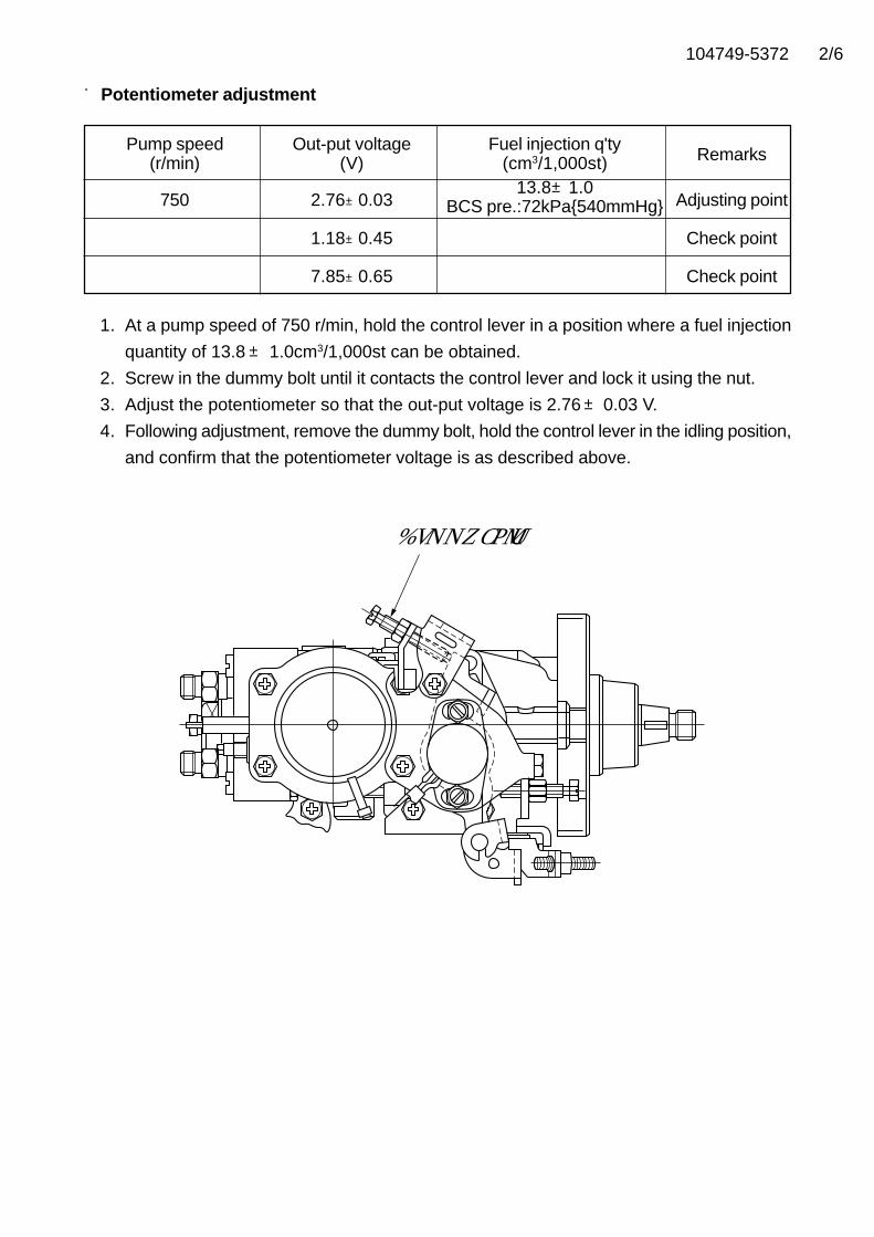
104749-5372 2/6
■Potentiometer adjustment
Pump speed Out-put voltage Fuel injection q'tyRemarks(r/min) (V) (cm3/1,000st)
750 2.76±0.0313.8±1.0
Adjusting pointBCS pre.:72kPa{540mmHg}
1.18±0.45 Check point
7.85±0.65 Check point
1. At a pump speed of 750 r/min, hold the control lever in a position where a fuel injection
quantity of 13.8± 1.0cm3/1,000st can be obtained.
2. Screw in the dummy bolt until it contacts the control lever and lock it using the nut.
3. Adjust the potentiometer so that the out-put voltage is 2.76±0.03 V.
4. Following adjustment, remove the dummy bolt, hold the control lever in the idling position,
and confirm that the potentiometer voltage is as described above.
Dummy bolt
104749-5372 3/6
■V-FICD Adjustment (Adjust with W-FICD disengaged)
1. Adjust so that S=1+1mm. (Figure 1)
Fig.1
2. At a negative pressure of 53.3kPa {400mmHg} adjust the actuator stroke using the
adjusting screw so that L=0.84±0.1 (Figure 2)
Fig.2
Pin
Actuator shaftControl lever
S
Actuator
Locknut (T=1.2~1.5 N·m {0.12~0.15 kgf·m})
L
Stroke adjusting screw
104749-5372 4/6
■W-CSD adjustment
1. Timer stroke adjustment
Adjust the screw ① so that the timer stroke is as determined from the graph in Figure
3 (see next page.{Figures 1 and 3})
2. Intermediate lever position adjustment
Insert a shim (L=1.2±0.05) between the control lever ⑨ and the idle set screw ⑦, align
the intermediate lever ⑥ with the aligning mark and adjust the intermediate lever adjusting
screw so that it contacts the control lever. Then, fix the screw. (Figures 1 and 2)
3. FICD adjustment
Insert a shim (L±0.05) between the control lever and the idle set screw and adjust the
screw ② so that the CSD lever ③ operates the intermedate lever through the rod ④.
Then, fix the screw. (Figures 1,2 and 3)
Figure 1 Figure 2
LINE ON BRACKET 8
EDGE OF LEVER 6
①�
②�
③� ④�
⑤�
⑥�
⑨�
L
⑨�
⑤�
⑧�
⑦�
L
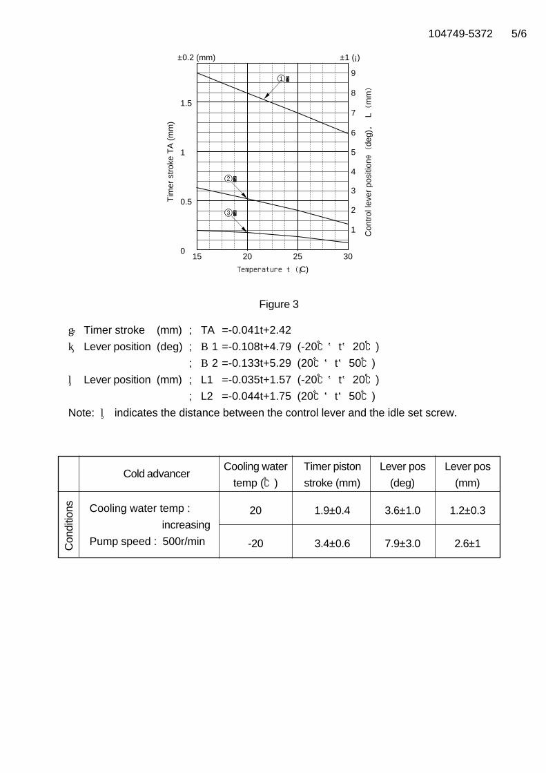
104749-5372
① Timer stroke (mm) ; TA =-0.041t+2.42
② Lever position (deg) ; θ1 =-0.108t+4.79 (-20℃≦t≦20℃)
; θ2 =-0.133t+5.29 (20℃≦t≦50℃)
③ Lever position (mm) ; L1 =-0.035t+1.57 (-20℃≦t≦20℃)
; L2 =-0.044t+1.75 (20℃≦t≦50℃)
Note: ③ indicates the distance between the control lever and the idle set screw.
Figure 3
Cold advancerCooling water Timer piston Lever pos Lever pos
temp (℃) stroke (mm) (deg) (mm)
20 1.9±0.4 3.6±1.0 1.2±0.3
-20 3.4±0.6 7.9±3.0 2.6±1
Cooling water temp :
increasing
Pump speed : 500r/minCon
ditio
ns
1
0.5
015 20 25
Temperature t (¡C)
30
1.57
6
9
±0.2 (mm) ±1 (¡)
8
5
4
3
2
1
Tim
er s
trok
e T
A (
mm
)
Con
trol
leve
r po
sitio
nθ(d
eg),
L (m
m)
①�
②�
③�
5/6
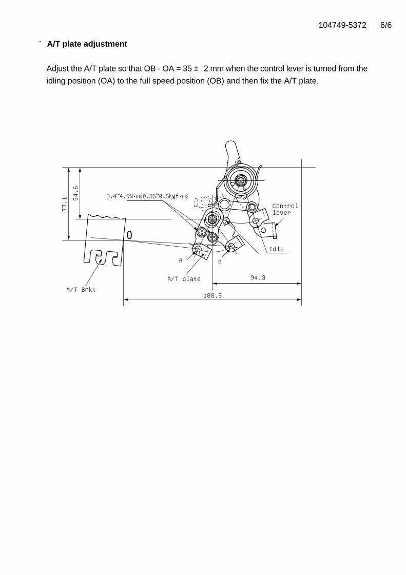
104749-5372
■■■■■A/T plate adjustment
Adjust the A/T plate so that OB - OA = 35 ± 2 mm when the control lever is turned from the
idling position (OA) to the full speed position (OB) and then fix the A/T plate.54.6
3.4~4.9N・m{0.35~0.5kgf・m}
A/T plate
Idle
Controllever
188.5A/T Brkt
A B
94.3
77.1
6/6
104749-7150
Not Bosch/Zexel
Product of DPICO
No information available
Refer to Kia
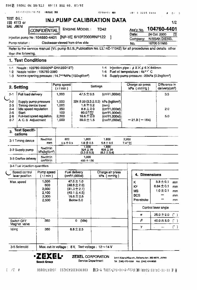


Ass’y No.Date:Company:No.
Refer to the service manual (VE pump B.I.S.;Publication No. EE14E-11042) for all procedures and details other
than the following.
1. Test Conditions
2. Setting
4. Dimensions
CONFIDENTIAL
INJ.PUMP CALIBRATION DATATEST OIL:ISO 4113 orSAE J967d
ENGINE MODEL :
Injection pump No : [NP-VE ]Pump rotation : Clockwise-viewed from drive side
Pump speed( r / min )
Settings Charge air presskPa { mmHg }
Difference indelivery(cm3)
Full load delivery
Supply pump pressureTiming device travelIdle speed regulationStartFull-load speed regulation
2-1
2-22-32-42-52-62-7
(cm3/1,000st)
kPa {kgf/cm2}(mm)(cm3/1,000st)(cm3/1,000st)(cm3/1,000st)
Pump speed( r / min )
Charge air presskPa { mmHg }
3. Test Specifi- cations
3-1 Timing device
3-2 Supply pump
3-3 Overflow delivery
N=r/min mm
N=r/minkPa{kgf/cm2}
N=r/mincm3/min
3-4 Fuel injection quantities
Speed controllever position
Fuel delivery(cm3/1,000st)
Max. speed
Switch OFFMagnet valve
Idling
3-5 Solenoid
KKFMSBCSPre-stroke
mmmmmmmmmm
(° )
(° )
(° )-
Control lever angle
Bosch Automotive Systems CorporationService Department
3-4-1 Kitano,Niiza-shi, Saitama-ken, 352-8572, JAPAN
Tel. (048) 470-1559 Fax. (048) 474-9856
TD42
6/10F2000RNP126104660-4441
1,000
1,0001,000 350 1002,3001,200
50.9±0.5
324±29 {3.3±0.2} 1.6±0.2
8.8±2 60+ 20.0 - 15.0
16.6±2 2.5±0.2
3.5
2.0
5.0
800 1,000 1,800 2,2000.5±0.5 1.6±0.3 5.8±0.5 7.4 +0.4 -0.5
1,000 1,800324±29 608±29
{3.3±0.3} {6.2±0.4}
1,000400±130
6001,0002,0002,1002,3002,500
52.6±2.050.9±1.044.7±2.143.8±4.516.6±2.5Below 5
3.3±0.16.64±0.11.0±0.1
--
25±2
40±5
8.8±2.5
0 Below 5
350
350 250
1/3
104760-444119 July 2002NISSAN DIESEL16700 51N62
1
Max. cut-in voltage : 8 V, Test voltage : 12~14 V
Load-timer Adjustment (mm)
(Idle)
Charge air press
(Full)
1-4 Injection pipe : ø2×ø6×840mm1-5 Fuel oil temperature : 45+5°C1-6 Supply pump pressure : 20kPa {0.2kgf/cm2}
1-1 Nozzle : 105780-0000(NP-DN12SD12T)1-2 Nozzle holder : 105780-2080(EF8511/9)1-3 Nozzle opening pressure : 14.7+0.49MPa {150+5kgf/cm2}
(Full)
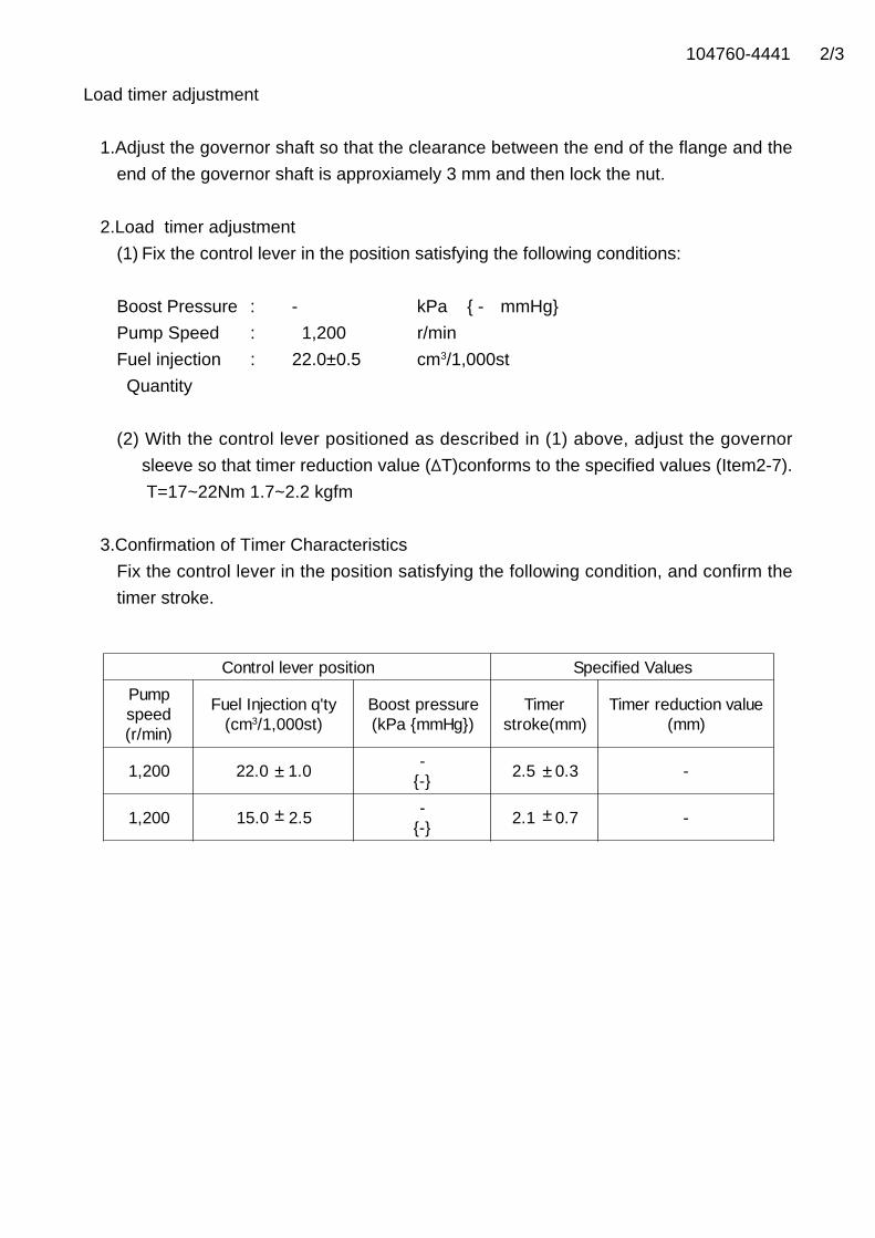
104760-4441 2/3
Load timer adjustment
1.Adjust the governor shaft so that the clearance between the end of the flange and the
end of the governor shaft is approxiamely 3 mm and then lock the nut.
2.Load timer adjustment
(1) Fix the control lever in the position satisfying the following conditions:
Boost Pressure : - kPa { - mmHg}
Pump Speed : 1,200 r/min
Fuel injection : 22.0±0.5 cm3/1,000st
Quantity
(2) With the control lever positioned as described in (1) above, adjust the governor
sleeve so that timer reduction value ( T)conforms to the specified values (Item2-7).
T=17~22Nm 1.7~2.2 kgfm
3.Confirmation of Timer Characteristics
Fix the control lever in the position satisfying the following condition, and confirm the
timer stroke.
Control lever position Specified Values
Pumpspeed(r/min)
Fuel Injection q'ty(cm3/1,000st)
Boost pressure(kPa {mmHg})
Timerstroke(mm)
Timer reduction value(mm)
1,200 22.0 1.0-
{-}2.5 0.3 -
1,200 15.0 2.5-
{-}2.1 0.7 -±
±
±
±
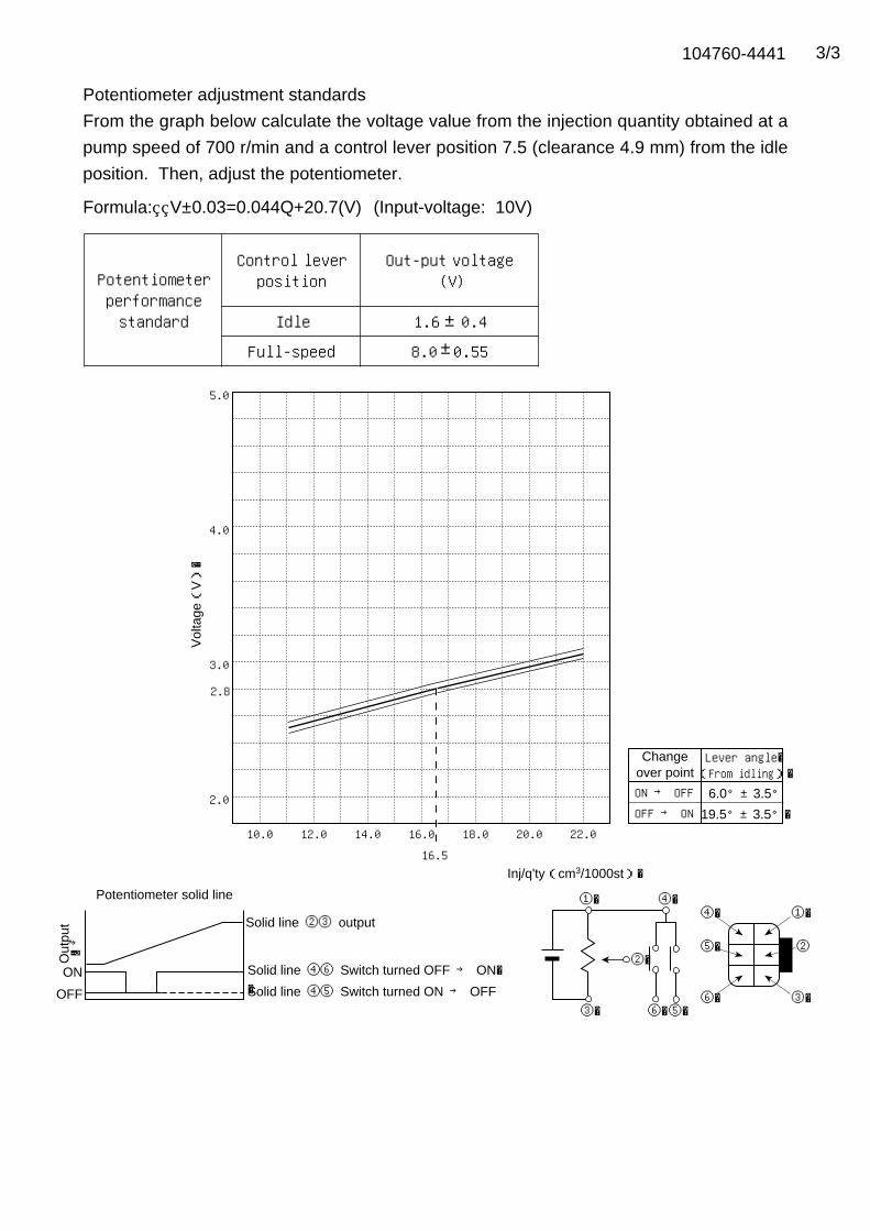
104760-4441 3/3
Formula: V±0.03=0.044Q+20.7(V) (Input-voltage: 10V)
①�Potentiometer solid line
→�
Solid line ②③ output
5.0
4.0
3.0
2.0
Vol
tage(
V)�
10.0 12.0 14.0 16.0 18.0 20.0 22.0
Inj/q'ty(cm3/1000st)�
④�
⑤� ②�
⑥�
①�
③�
④�
③� ⑥�⑤�
②�ON
OFF
Changeover point
ON → OFF 6.0°±3.5°OFF → ON 19.5°±3.5°�
Lever angle�(From idling)�
Out
put
Solid line ④⑤ Switch turned ON → OFF
Solid line ④⑥ Switch turned OFF → ON��
2.8
16.5
Potentiometerperformancestandard
Control leverposition
Out-put voltage(V)
Idle 1.6 0.4
Full-speed 8.0 0.55±
±
Potentiometer adjustment standards
From the graph below calculate the voltage value from the injection quantity obtained at a
pump speed of 700 r/min and a control lever position 7.5 (clearance 4.9 mm) from the idle
position. Then, adjust the potentiometer.
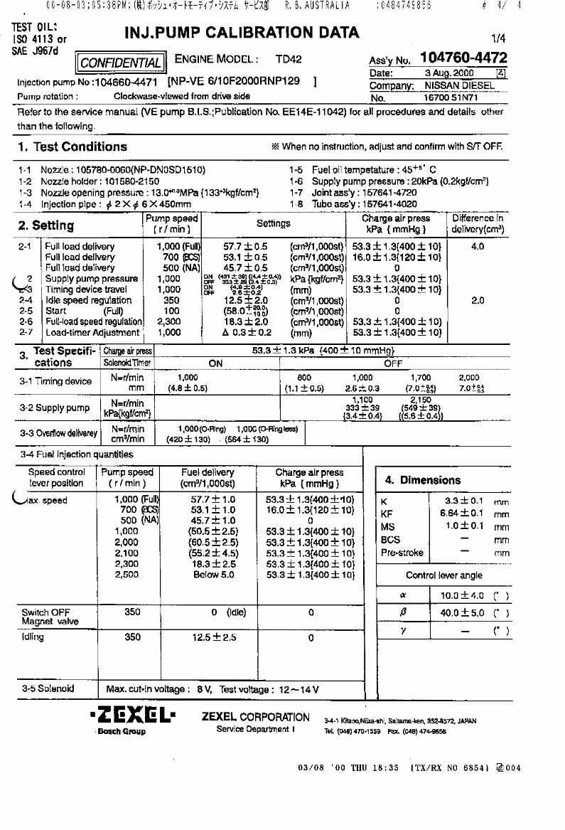

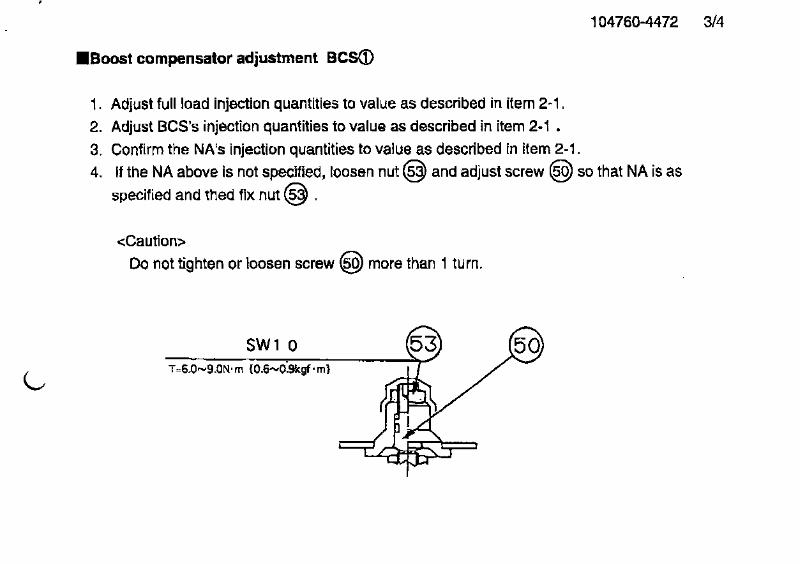

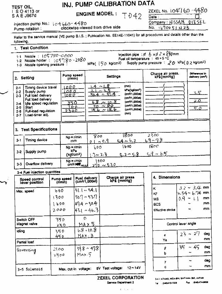
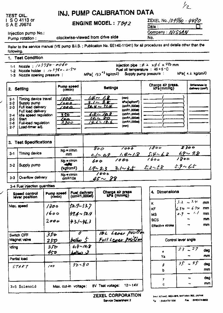
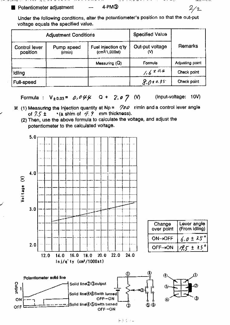

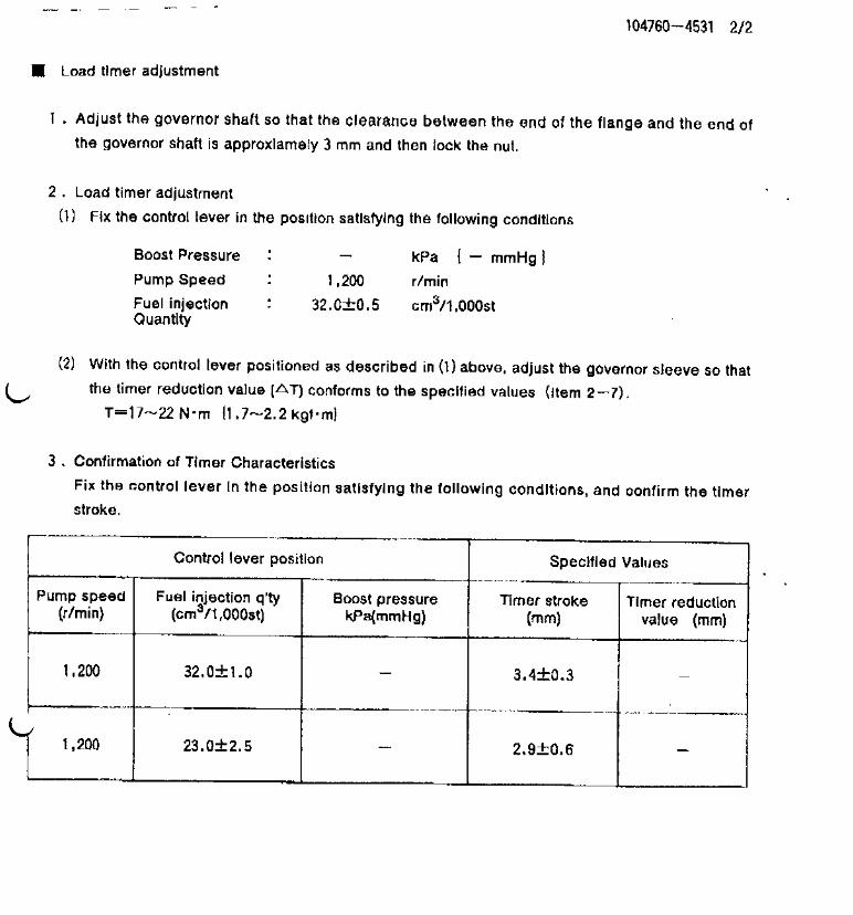
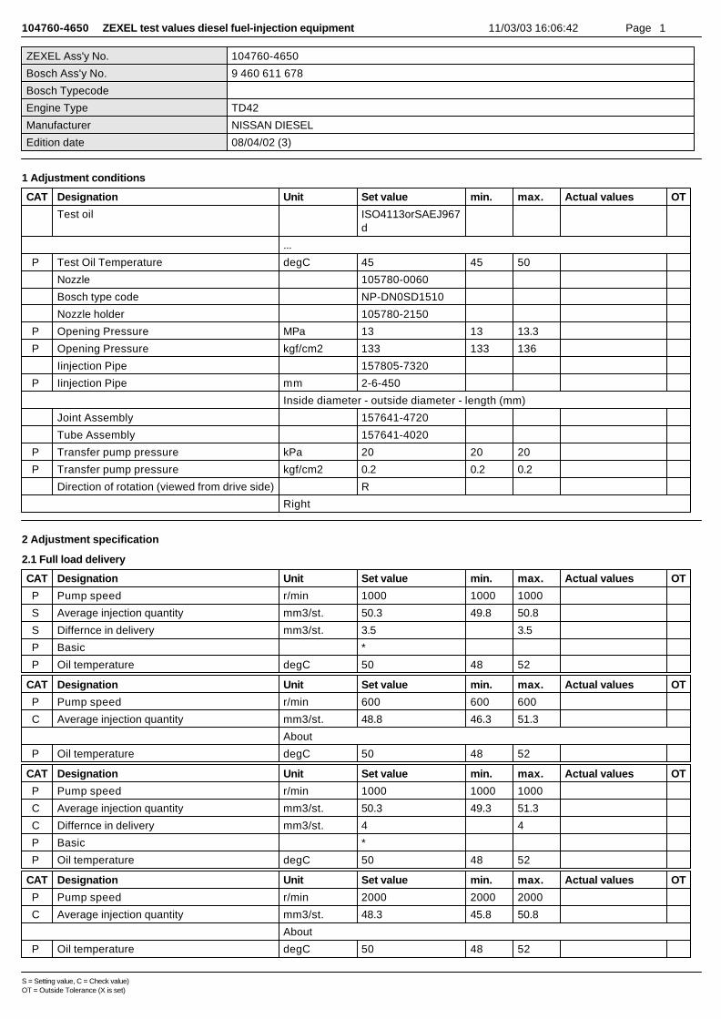
104760-4650 ZEXEL test values diesel fuel-injection equipment 11/03/03 16:06:42 Page 1
ZEXEL Ass'y No. 104760-4650
Bosch Ass'y No. 9 460 611 678
Bosch Typecode
Engine Type TD42
Manufacturer NISSAN DIESEL
Edition date 08/04/02 (3)
1 Adjustment conditions
CAT Designation Unit Set value min. max. Actual values OT
Test oil ISO4113orSAEJ967d
...
P Test Oil Temperature degC 45 45 50
Nozzle 105780-0060
Bosch type code NP-DN0SD1510
Nozzle holder 105780-2150
P Opening Pressure MPa 13 13 13.3
P Opening Pressure kgf/cm2 133 133 136
Iinjection Pipe 157805-7320
P Iinjection Pipe mm 2-6-450
Inside diameter - outside diameter - length (mm)
Joint Assembly 157641-4720
Tube Assembly 157641-4020
P Transfer pump pressure kPa 20 20 20
P Transfer pump pressure kgf/cm2 0.2 0.2 0.2
Direction of rotation (viewed from drive side) R
Right
2 Adjustment specification
2.1 Full load delivery
CAT Designation Unit Set value min. max. Actual values OT
P Pump speed r/min 1000 1000 1000
S Average injection quantity mm3/st. 50.3 49.8 50.8
S Differnce in delivery mm3/st. 3.5 3.5
P Basic *
P Oil temperature degC 50 48 52
CAT Designation Unit Set value min. max. Actual values OT
P Pump speed r/min 600 600 600
C Average injection quantity mm3/st. 48.8 46.3 51.3
About
P Oil temperature degC 50 48 52
CAT Designation Unit Set value min. max. Actual values OT
P Pump speed r/min 1000 1000 1000
C Average injection quantity mm3/st. 50.3 49.3 51.3
C Differnce in delivery mm3/st. 4 4
P Basic *
P Oil temperature degC 50 48 52
CAT Designation Unit Set value min. max. Actual values OT
P Pump speed r/min 2000 2000 2000
C Average injection quantity mm3/st. 48.3 45.8 50.8
About
P Oil temperature degC 50 48 52
S = Setting value, C = Check value)OT = Outside Tolerance (X is set)

104760-4650 ZEXEL test values diesel fuel-injection equipment 11/03/03 16:06:42 Page 2
2.2 Governing
CAT Designation Unit Set value min. max. Actual values OT
P Pump speed r/min 2300 2300 2300
S Average injection quantity mm3/st. 17.8 15.8 19.8
S Differnce in delivery mm3/st. 5 5
P Basic *
P Oil temperature degC 52 50 54
CAT Designation Unit Set value min. max. Actual values OT
P Pump speed r/min 2500 2500 2500
C Average injection quantity mm3/st. 5 5
P Oil temperature degC 55 52 58
CAT Designation Unit Set value min. max. Actual values OT
P Pump speed r/min 2100 2100 2100
C Average injection quantity mm3/st. 48.1 43.6 52.6
About
P Oil temperature degC 52 50 54
CAT Designation Unit Set value min. max. Actual values OT
P Pump speed r/min 2300 2300 2300
C Average injection quantity mm3/st. 17.8 15.3 20.3
P Basic *
P Oil temperature degC 52 50 54
2.3 Idle
CAT Designation Unit Set value min. max. Actual values OT
P Pump speed r/min 350 350 350
S Average injection quantity mm3/st. 10.1 8.1 12.1
S Differnce in delivery mm3/st. 2 2
P Basic *
P Oil temperature degC 48 46 50
CAT Designation Unit Set value min. max. Actual values OT
P Pump speed r/min 350 350 350
C Average injection quantity mm3/st. 10.1 7.6 12.6
C Differnce in delivery mm3/st. 2.5 2.5
P Basic *
P Oil temperature degC 48 46 50
2.4 Start
CAT Designation Unit Set value min. max. Actual values OT
P Pump speed r/min 100 100 100
S Average injection quantity mm3/st. 60 50 80
P Basic *
P Oil temperature degC 48 46 50
Remarks
Full
CAT Designation Unit Set value min. max. Actual values OT
P Pump speed r/min 100 100 100
C Average injection quantity mm3/st. 60 50 80
P Oil temperature degC 48 46 50
Remarks
Full
2.5 Stop
CAT Designation Unit Set value min. max. Actual values OT
P Pump speed r/min 350 350 350
C Average injection quantity mm3/st. 0 0 0
S = Setting value, C = Check value)OT = Outside Tolerance (X is set)
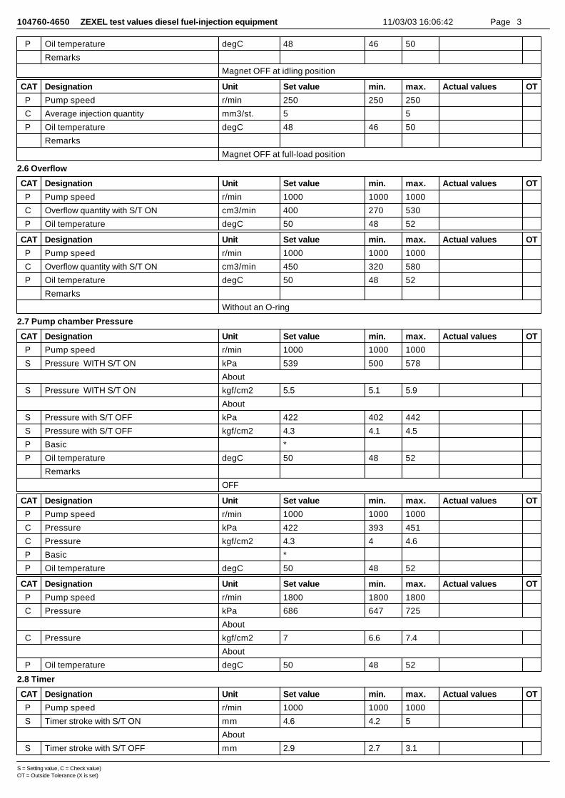
104760-4650 ZEXEL test values diesel fuel-injection equipment 11/03/03 16:06:42 Page 3
P Oil temperature degC 48 46 50
Remarks
Magnet OFF at idling position
CAT Designation Unit Set value min. max. Actual values OT
P Pump speed r/min 250 250 250
C Average injection quantity mm3/st. 5 5
P Oil temperature degC 48 46 50
Remarks
Magnet OFF at full-load position
2.6 Overflow
CAT Designation Unit Set value min. max. Actual values OT
P Pump speed r/min 1000 1000 1000
C Overflow quantity with S/T ON cm3/min 400 270 530
P Oil temperature degC 50 48 52
CAT Designation Unit Set value min. max. Actual values OT
P Pump speed r/min 1000 1000 1000
C Overflow quantity with S/T ON cm3/min 450 320 580
P Oil temperature degC 50 48 52
Remarks
Without an O-ring
2.7 Pump chamber Pressure
CAT Designation Unit Set value min. max. Actual values OT
P Pump speed r/min 1000 1000 1000
S Pressure WITH S/T ON kPa 539 500 578
About
S Pressure WITH S/T ON kgf/cm2 5.5 5.1 5.9
About
S Pressure with S/T OFF kPa 422 402 442
S Pressure with S/T OFF kgf/cm2 4.3 4.1 4.5
P Basic *
P Oil temperature degC 50 48 52
Remarks
OFF
CAT Designation Unit Set value min. max. Actual values OT
P Pump speed r/min 1000 1000 1000
C Pressure kPa 422 393 451
C Pressure kgf/cm2 4.3 4 4.6
P Basic *
P Oil temperature degC 50 48 52
CAT Designation Unit Set value min. max. Actual values OT
P Pump speed r/min 1800 1800 1800
C Pressure kPa 686 647 725
About
C Pressure kgf/cm2 7 6.6 7.4
About
P Oil temperature degC 50 48 52
2.8 Timer
CAT Designation Unit Set value min. max. Actual values OT
P Pump speed r/min 1000 1000 1000
S Timer stroke with S/T ON mm 4.6 4.2 5
About
S Timer stroke with S/T OFF mm 2.9 2.7 3.1
S = Setting value, C = Check value)OT = Outside Tolerance (X is set)
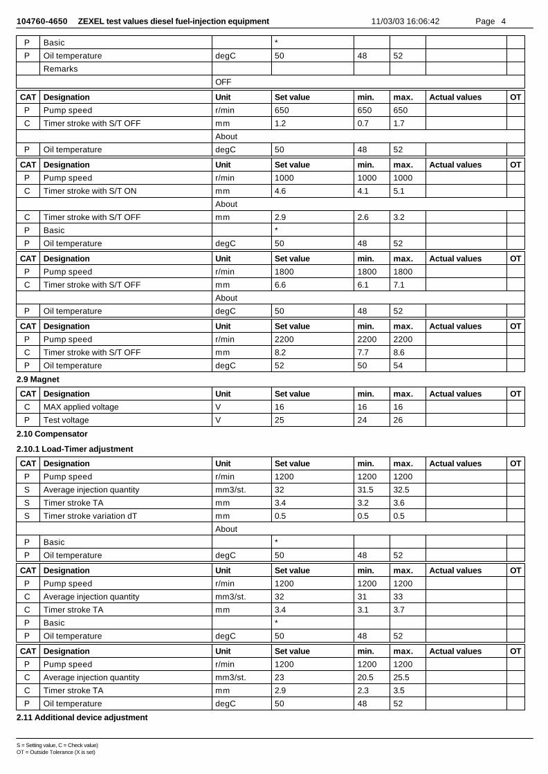
104760-4650 ZEXEL test values diesel fuel-injection equipment 11/03/03 16:06:42 Page 4
P Basic *
P Oil temperature degC 50 48 52
Remarks
OFF
CAT Designation Unit Set value min. max. Actual values OT
P Pump speed r/min 650 650 650
C Timer stroke with S/T OFF mm 1.2 0.7 1.7
About
P Oil temperature degC 50 48 52
CAT Designation Unit Set value min. max. Actual values OT
P Pump speed r/min 1000 1000 1000
C Timer stroke with S/T ON mm 4.6 4.1 5.1
About
C Timer stroke with S/T OFF mm 2.9 2.6 3.2
P Basic *
P Oil temperature degC 50 48 52
CAT Designation Unit Set value min. max. Actual values OT
P Pump speed r/min 1800 1800 1800
C Timer stroke with S/T OFF mm 6.6 6.1 7.1
About
P Oil temperature degC 50 48 52
CAT Designation Unit Set value min. max. Actual values OT
P Pump speed r/min 2200 2200 2200
C Timer stroke with S/T OFF mm 8.2 7.7 8.6
P Oil temperature degC 52 50 54
2.9 Magnet
CAT Designation Unit Set value min. max. Actual values OT
C MAX applied voltage V 16 16 16
P Test voltage V 25 24 26
2.10 Compensator
2.10.1 Load-Timer adjustment
CAT Designation Unit Set value min. max. Actual values OT
P Pump speed r/min 1200 1200 1200
S Average injection quantity mm3/st. 32 31.5 32.5
S Timer stroke TA mm 3.4 3.2 3.6
S Timer stroke variation dT mm 0.5 0.5 0.5
About
P Basic *
P Oil temperature degC 50 48 52
CAT Designation Unit Set value min. max. Actual values OT
P Pump speed r/min 1200 1200 1200
C Average injection quantity mm3/st. 32 31 33
C Timer stroke TA mm 3.4 3.1 3.7
P Basic *
P Oil temperature degC 50 48 52
CAT Designation Unit Set value min. max. Actual values OT
P Pump speed r/min 1200 1200 1200
C Average injection quantity mm3/st. 23 20.5 25.5
C Timer stroke TA mm 2.9 2.3 3.5
P Oil temperature degC 50 48 52
2.11 Additional device adjustment
S = Setting value, C = Check value)OT = Outside Tolerance (X is set)

104760-4650 ZEXEL test values diesel fuel-injection equipment 11/03/03 16:06:42 Page 5
2.11.1 Additional device 1
Name ACCELERATOR SWITCH ADJ
a=5deg+2degd=25+-2degSW=SW10T=6~9Nm(0.6~0.9kgfm)L1=3.3mm
a=5deg+2degb=5degc=5degL1=3.3+-0.13mm
Accelerator switch adjustmentON - OFF changeover point: from idle to a (shim thickness A = L)Idle~c: ONc~full: OFFA = shim thicknessB = idle lever position
3 Assembly dimension
CAT Designation Unit Set value min. max. Actual values OT
S K dimension mm 3.3 3.2 3.4
S KF dimension mm 5.8 5.7 5.9
S MS dimension mm 1 0.9 1.1
S Control lever angle alpha deg. 25 23 27
S Control lever angle beta deg. 40 35 45
S = Setting value, C = Check value)OT = Outside Tolerance (X is set)
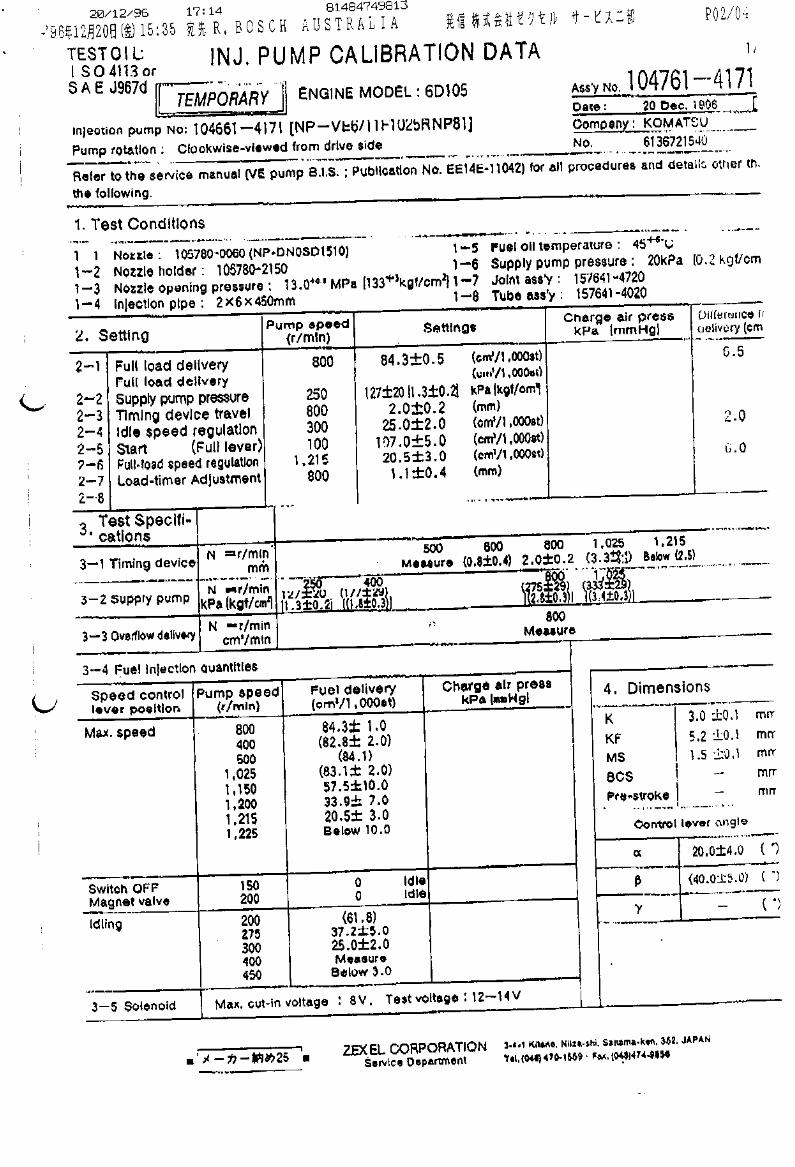
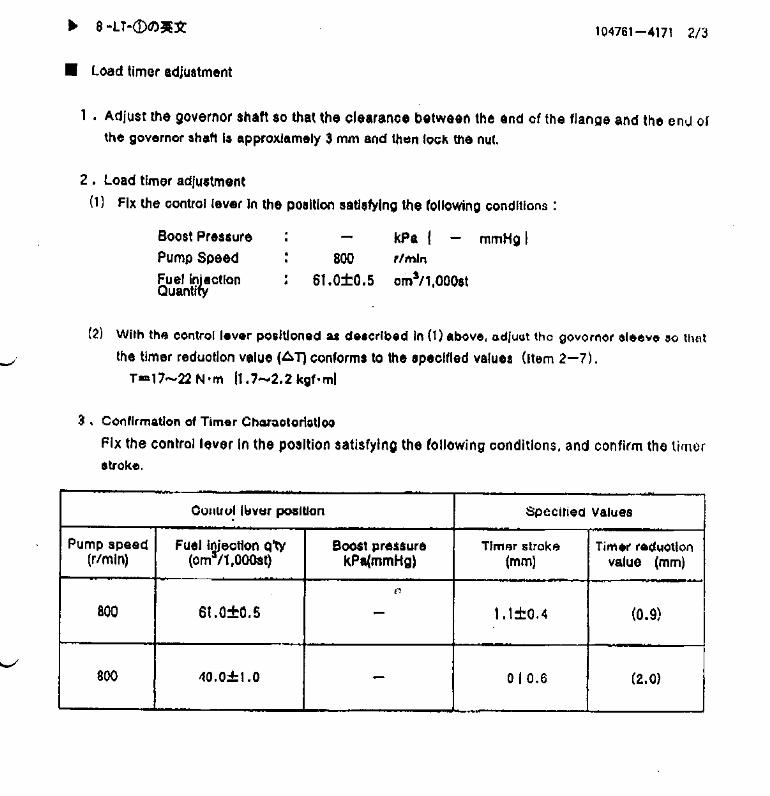
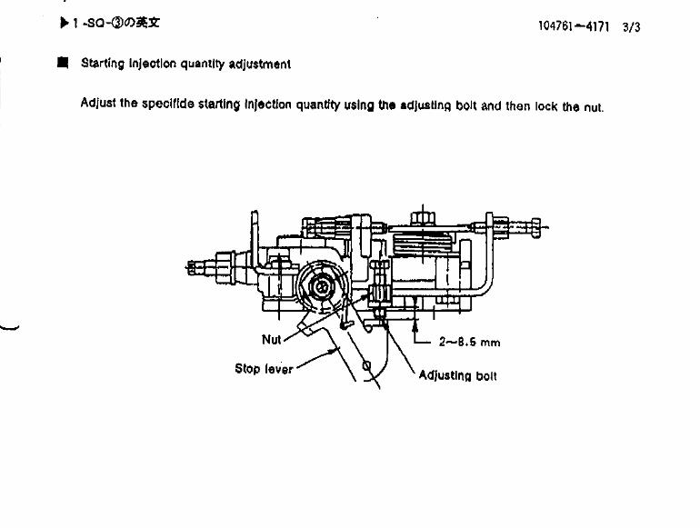

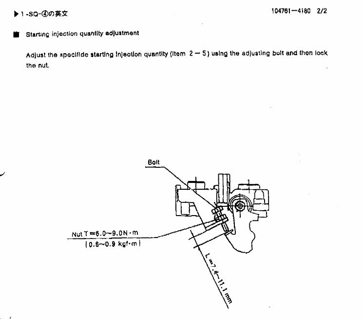
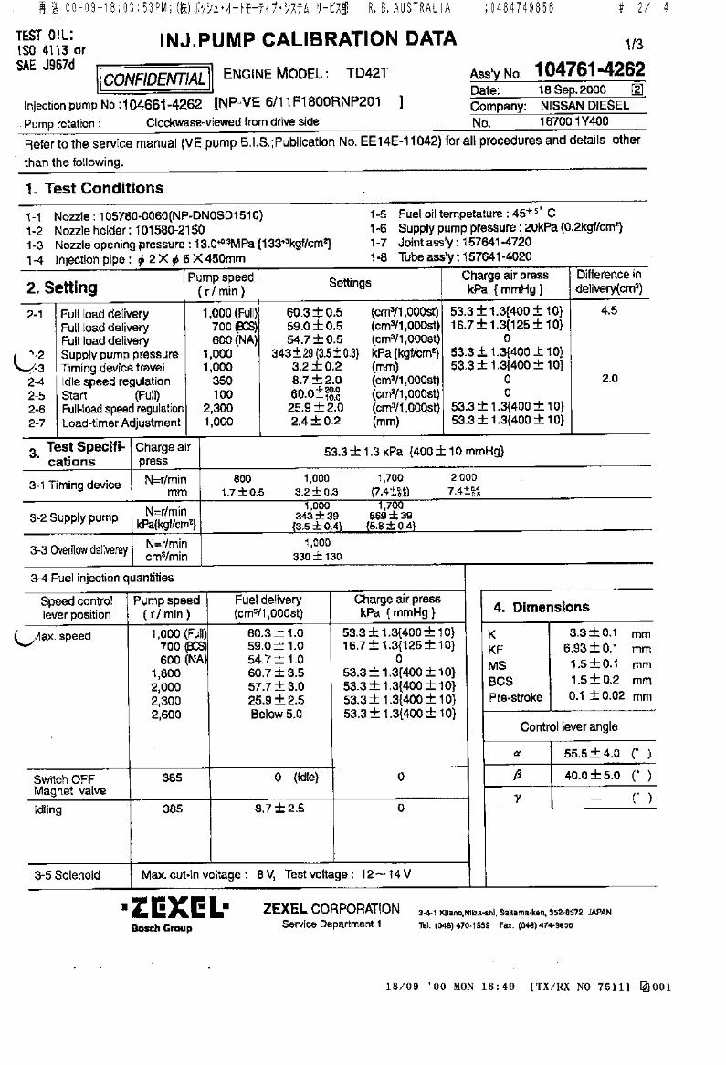
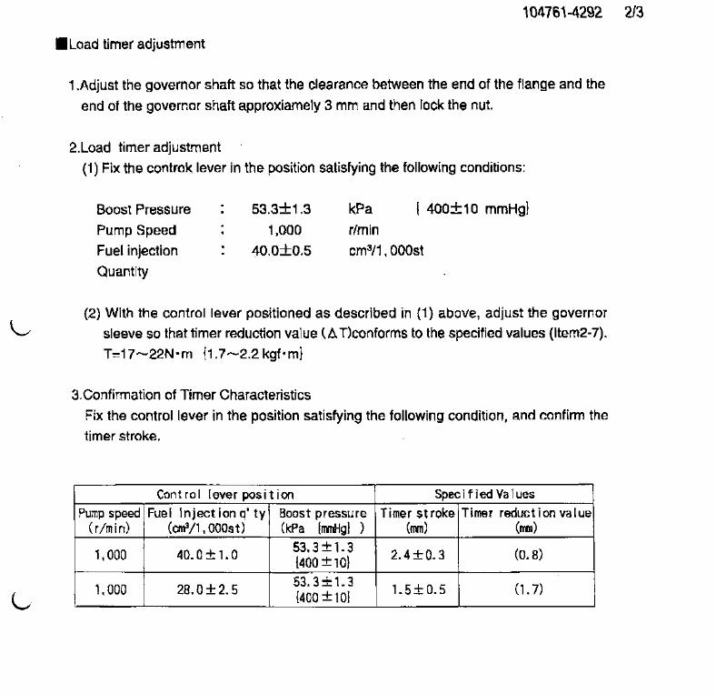


Test Data
104761-4290
use
104761-4260
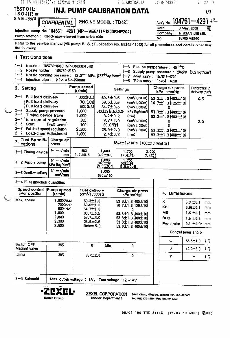

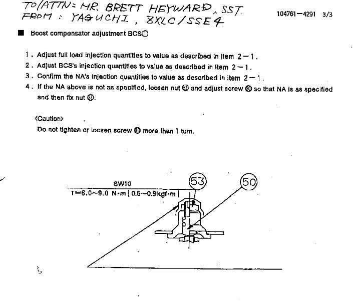

2003/02/25 09:53:05 Page 1
ZexelAssyZexelAssyManuf.
Assy nameManufacturer No. Engine Type Manufacturer No.
Make dataRenew data
2003/02/252003/02/25
104761-4371104761-4370NISSAN DIESEL 1006 TD42T 16700VC700
P Parts No. Parts name B.T.C. Modify Edition data Kinds VECylinder 6
[1] Adjustment conditionsDesignation Unit PSC Set value RemarkTest oil ISO4113orSAEJ967dTest Oil Temperature degC P 45+5Nozzle 105780-0060BOSCH type code NP-DN0SD1510Nozzle holder 105780-2150Opening Pressure MPa P 13.0+0.3Opening Pressure kgf/cm2 P 133+3Injection Pipe No. 157805-7320Injection Pipe mm P 2-6-450 Inside Die.-Outside Die.-Length(mm)Joint Ass'y 157641-4720Tube Ass'y 157641-4020Transfer pump pressure kPa P 20Transfer pump pressure kgf/cm2 P 0.2Dir.of rot.viewed fromdriveside R RightChecker NO. 407980-228*ECU NO. 407913-1342ECU Voltage D.C. V TCV Drive Voltage D.C. V TCV Drive Voltage Hz Wire Harness 407980-2300Inter. Harness 157992-8900
[1] Adjustment specification[2] Full load delivery
Pump speed Boost pressure Boost pressure Boost pressure TCV DUTY (%) F TCV 60Hz
Ave.inj.qty Diff in dely Basic Test oil Remark
r/min kPa kgf/cm2 mmHg % mm3/st. mm3/st. degC500P 0P 0P 100P 49.7~50.7S *P 48+-2P NA700P 25.4~28.0P 190~210P 100P 55.9~56.9S *P 50+-2P BCS1000P 52.0~62.5P 390~410P 100P 51.5~62.5S 5.0--S *P 50+-2P FULL500P 0P 0P 100P 49.2~51.2C *P 48+-2P NA700P 25.4~28.0P 190~210P 100P 55.4~57.4C *P 50+-2P BCS1000P 52.0~54.6P 390~410P 100P 61.0~63.0C *P 50+-2P FULL1250P 52.0~54.6P 390~410P 100P 57.7~59.7C 50+-2P1800P 52.7~60.7P 390~410P 100P 52.7~60.7C 50+-2P
[2] GoverningPump speed Boost pressure Boost pressure Boost pressure TCV DUTY (%) F TCV
60HzAve.inj.qty Diff in dely Basic Test oil Remark
r/min kPa kgf/cm2 mmHg % mm3/st. mm3/st. degC2300P 52.0~54.6P 390~410P 100P 20.8~24.8S *P 52+-2P2500P 52.0~54.6P 390~410P 100P 5.0--C 55+-3P2300P 52.0~54.6P 390~410P 100P 20.3~25.3C 52+-2P
[2] IdlePump speed Boost pressure Boost pressure Boost pressure TCV DUTY (%) F TCV
60HzAve.inj.qty Diff in dely Basic Test oil Remark
r/min kPa kgf/cm2 mmHg % mm3/st. mm3/st. degC385P 0P 0P 100P 4.6~8.6S 2.0--S *P 48+-2P385P 0P 0P 100P 4.1~9.1C 48+-2P650P 0P 0P 100P 3.0--C 50+-2P

Ass'y NO. 104761-4371 2003/02/25 09:53:05 Page 2
[2] Partial quantityPump speed Boost pressure Boost pressure Boost pressure Ave.inj.qty Diff in dely Basic Test oil Thickness guage Remarkr/min kPa kgf/cm2 mmHg mm3/st. mm3/st. degC mm
[2] StartPump speed Boost pressure Boost pressure Boost pressure TCV DUTY (%) F TCV
60HzAve.inj.qty Diff in dely Basic Test oil Remark
r/min kPa kgf/cm2 mmHg % mm3/st. mm3/st. degC100P 0P 0P 0P 51.5~81.5S *P 48+-2P FULL
[2] StopPump speed Boost pressure Boost pressure Boost pressure TCV DUTY (%) F TCV
60HzAve.inj.qty Diff in dely Basic Test oil Remark
r/min kPa kgf/cm2 mmHg % mm3/st. mm3/st. degC385P 0P 0P 100P 0C 48+-2P Magnet OFF150P 0P 0P 0P 5--C 48+-2P Magnet OFF
[2] OverflowPump speed Boost pressure Boost pressure Boost pressure TCV DUTY (%) F TCV
60HzOverflow quantity S/T ON Overflow qtyS/T OFFOverflow qtyBasic Test oil
r/min kPa kgf/cm2 mmHg % cm3/min cm3/min cm3/min degC1100P 52.0~54.6P 390~410P 100P 468~732C 50+-2P
Remark
[2] Pump chamber PressurePump speed Boost pressure Boost pressure Boost pressure TCV DUTY (%) F TCV
60HzPressure Pressure S/T ON Pressure S/T ON Pressure S/T OFF Pressure
r/min kPa kgf/cm2 mmHg % kPa kgf/cm2 kPa kgf/cm2 kPa1100P 52.0~54.6P 390~410P 100P 550~608S 5.6~6.2S100P 52.0~54.6P 390~410P 100P 294++C 3.0++C1100P 52.0~54.6P 390~410P 100P 540~618C 5.5~6.3C1800P 52.0~54.6P 390~410P 100P 618~716C 6.3~7.3C
S/T OFF Pressure Basic Test oil Remark
kgf/cm2 degC*P 50+-2P
48+-2P50+-2P50+-2P
[2] TimerPump speed Boost pressure Boost pressure Boost pressure TCV DUTY (%) F TCV
60HzTimer stroke S/T ON Timer
strokeS/T OFF Timer stroke
Basic Test oil
r/min kPa kgf/cm2 mmHg % mm mm mm degC1100P 52.0~54.6P 390~410P 70P 3.2~3.8S *P 50+-2P500P 52.0~54.6P 390~410P 100P 3.6~7.6C 48+-2P1100P 52.0~54.6P 390~410P 100P 5.0~9.0C 50+-2P1100P 52.0~54.6P 390~410P 70P 3.1~3.9C 50+-2P1100P 52.0~54.6P 390~410P 0P 0C 50+-2P1800P 52.0~54.6P 390~410P 100P 6.5~7.4C 50+-2P
Remark
[2] TPS OutputPump speed Boost pressure Boost pressure Boost pressure TCV DUTY (%) F TCV
60HzTA-ist Basic Test oil Remark
r/min kPa kgf/cm2 mmHg % V degC[2] Magnet

Ass'y NO. 104761-4371 2003/02/25 09:53:05 Page 3
Designation Unit PSC Set value RemarkMAX applied voltage V C 8Test voltage V P 12~14
[2] [3] Load-Timer adjustment
Designation Image Explanation 2 Explanation 3 Explanation 4
Pump speed Boost pressure Boost pressure Boost pressure Ave.inj.qty Timer stroke TA Timer strokeChange volume ΔT
Basic Test oil Remark
r/min kPa kgf/cm2 mmHg mm3/st. mm mm degC[3] ACS adjustment
Designation Image Explanation 2 Explanation 3 Explanation 4
Pump speed Height Pressure differencePressure differenceAve.inj.qty Decrease quantity Decrease rate Basic Test oil Remarkr/min m kPa mmHg mm3/st. mm3/st. % degC[3] BCS adjustment
Designation Image Explanation 2 Explanation 3 Explanation 4
[2] Additional device adjustment[3] Additional device1
Designation Image Explanation 2 Explanation 3 Explanation 4POTENTIOMETER ADJUSTMENT 4-PM5-1 4-PM5-2F 4-PM5-3 104761-4370 4-PM5-4 104761-4370N1=1240r/minQ1=40.6+-1.0cm3/1,000stV1=6.00+-0.03VV2=1.04+-0.69VV3=8.18+-0.61Va=-degV1=6.00+-0.03VP1=0kPaP2=0mmHgVi=10V
Potentiometer adjustment standards (Bosch mini mass piping)1.Applied voltage=Vi2.Boost pressure =P1kPa{P2mmHg}3.Adjust the dummy bolt to determine the control lever position for the above adjusting point and then fix the dummy bolt so that itcontacts the lever. 4.In the above position, adjust the installation position of the potentiometer so that the output voltage is 6.00±0.03 V. 5.Fix the potentiometer and remove the dummy bolt.At TCV duty ratio 100%A=Adjusting pointB=Check pointC=Control lever positionN=Pump speed(r/min)V=Potentiometer output voltage(V)Q=Injection quantity(cm3/1000st)C1=IdleC2=Full speed
[3] Additional device 2Designation Image Explanation 2 Explanation 3 Explanation 4
[3] Additional device 3Designation Image Explanation 2 Explanation 3 Explanation 4
[3] Additional device 4Designation Image Explanation 2 Explanation 3 Explanation 4
[3] Additional device 5Designation Image Explanation 2 Explanation 3 Explanation 4
[3] Additional device 6Designation Image Explanation 2 Explanation 3 Explanation 4
[3] Additional device 7Designation Image Explanation 2 Explanation 3 Explanation 4
Ass'y NO. 104761-4371 2003/02/25 09:53:05 Page 4
[3] Additional device 8Designation Image Explanation 2 Explanation 3 Explanation 4
[1] Assembly dimensionDesignation Unit PSC Set value RemarkK dimension mm S 3.2~3.4KF dimension mm S 6.66~6.86MS dimension mm S 1.2~1.4Effectiveness storoke mm BCS storoke mm S 2.7~3.1Pre-storoke mm S 0.08~0.12Control lever angle α deg. S 51.5~59.5Control lever angle β deg. S 38~48Control lever angle γ deg.
2003/02/25 09:51:55 Page 1
ZexelAssyZexelAssyManuf.
Assy nameManufacturer No. Engine Type Manufacturer No.
Make dataRenew data
2003/02/252003/02/25
104761-4381104761-4380NISSAN DIESEL 1006 TD42T 167001Y700
P Parts No. Parts name B.T.C. Modify Edition data Kinds VECylinder 6
[1] Adjustment conditionsDesignation Unit PSC Set value RemarkTest oil ISO4113orSAEJ967dTest Oil Temperature degC P 45+5Nozzle 105780-0060BOSCH type code NP-DN0SD1510Nozzle holder 105780-2150Opening Pressure MPa P 13.0+0.3Opening Pressure kgf/cm2 P 133+3Injection Pipe No. 157805-7320Injection Pipe mm P 2-6-450 Inside Die.-Outside Die.-Length(mm)Joint Ass'y 157641-4720Tube Ass'y 157641-4020Transfer pump pressure kPa P 20Transfer pump pressure kgf/cm2 P 0.2Dir.of rot.viewed fromdriveside R RightChecker NO. 407980-228*ECU NO. 407913-1342ECU Voltage D.C. V TCV Drive Voltage D.C. V TCV Drive Voltage Hz Wire Harness 407980-2300Inter. Harness 157992-8300
[1] Adjustment specification[2] Full load delivery
Pump speed Boost pressure Boost pressure Boost pressure TCV DUTY (%) F TCV 60Hz
Ave.inj.qty Diff in dely Basic Test oil Remark
r/min kPa kgf/cm2 mmHg % mm3/st. mm3/st. degC500P 0P 0P 100P 49.7~50.7S *P 48+-2P NA700P 25.4~28.0P 190~210P 100P 55.9~56.9S *P 50+-2P BCS1000P 52.0~54.6P 390~410P 100P 51.5~62.5S 5.0--S *P 50+-2P FULL500P 0P 0P 100P 49.2~51.2C *P 48+-2P NA700P 25.4~28.0P 190~210P 100P 55.4~57.4C *P 50+-2P BCS1000P 52.0~54.6P 390~410P 100P 61.0~63.0C *P 50+-2P FULL1250P 52.0~54.6P 390~410P 100P 57.7~59.7C 50+-2P1800P 52.0~54.6P 390~410P 100P 52.7~60.7C 50+-2P
[2] GoverningPump speed Boost pressure Boost pressure Boost pressure TCV DUTY (%) F TCV
60HzAve.inj.qty Diff in dely Basic Test oil Remark
r/min kPa kgf/cm2 mmHg % mm3/st. mm3/st. degC2300P 52.0~54.6P 390~410P 100P 20.8~24.8S *P 52+-2P2500P 52.0~54.6P 390~410P 100P 5.0--C 55+-3P2300P 52.0~54.6P 390~410P 100P 20.3~25.3C 52+-2P
[2] IdlePump speed Boost pressure Boost pressure Boost pressure TCV DUTY (%) F TCV
60HzAve.inj.qty Diff in dely Basic Test oil Remark
r/min kPa kgf/cm2 mmHg % mm3/st. mm3/st. degC385P 0P 0P 100P 4.6~8.6S 2.0--S *P 48+-2P385P 0P 0P 100P 4.1~9.1C 48+-2P650P 0P 0P 100P 3.0--C 50+-2P
Ass'y NO. 104761-4381 2003/02/25 09:51:55 Page 2
[2] Partial quantityPump speed Boost pressure Boost pressure Boost pressure 平均噴射量 Diff in dely Basic Test oil Thickness guage Remarkr/min kPa kgf/cm2 mmHg mm3/st. mm3/st. degC mm
[2] StartPump speed Boost pressure Boost pressure Boost pressure TCV DUTY (%) F TCV
60HzAve.inj.qty Diff in dely Basic Test oil Remark
r/min kPa kgf/cm2 mmHg % mm3/st. mm3/st. degC100P 0P 0P 0P 51.5~81.5S *P 48+-2P FULL
[2] StopPump speed Boost pressure Boost pressure Boost pressure TCV DUTY (%) F TCV
60HzAve.inj.qty Diff in dely Basic Test oil Remark
r/min kPa kgf/cm2 mmHg % mm3/st. mm3/st. degC385P 0P 0P 100P 0C 48+-2P Magnet OFF150P 0P 0P 0P 5--C 48+-2P Magnet OFF
[2] OverflowPump speed Boost pressure Boost pressure Boost pressure TCV DUTY (%) F TCV
60HzOverflow quantity S/T ON Overflow qtyS/T OFFOverflow qtyBasic Test oil
r/min kPa kgf/cm2 mmHg % cm3/min cm3/min cm3/min degC1100P 52.0~54.6P 390~410P 100P 468~732C 50+-2P
Remark
[2] Pump chamber PressurePump speed Boost pressure Boost pressure Boost pressure TCV DUTY (%) F TCV
60HzPressure Pressure S/T ON Pressure S/T ON Pressure S/T OFF Pressure
r/min kPa kgf/cm2 mmHg % kPa kgf/cm2 kPa kgf/cm2 kPa1100P 52.0~54.6P 390~410P 100P 550~608S 5.6~6.2S100P 52.0~54.6P 390~410P 100P 294++C 3.0++C1100P 52.0~54.6P 390~410P 100P 540~618C 5.5~6.3C1800P 52.0~54.6P 390~410P 100P 618~716C 6.3~7.3C
S/T OFF Pressure Basic Test oil Remark
kgf/cm2 degC*P 50+-2P
48+-2P50+-2P50+-2P
[2] TimerPump speed Boost pressure Boost pressure Boost pressure TCV DUTY (%) F TCV
60HzTimer stroke S/T ON Timer
strokeS/T OFF Timer stroke
Basic Test oil
r/min kPa kgf/cm2 mmHg % mm mm mm degC1100P 52.0~54.6P 390~410P 70P 3.2~3.8S *P 50+-2P500P 52.0~54.6P 390~410P 100P 3.6~7.6C 48+-2P1100P 52.0~54.6P 390~410P 100P 5.0~9.0C 50+-2P1100P 52.0~54.6P 390~410P 70P 3.1~3.9C 50+-2P1100P 52.0~54.6P 390~410P 0P 0C 50+-2P1800P 52.0~54.6P 390~410P 100P 6.5~7.4C 50+-2P
Remark
[2] TPS OutputPump speed Boost pressure Boost pressure Boost pressure TCV DUTY (%) F TCV
60HzTA-ist Basic Test oil Remark
r/min kPa kgf/cm2 mmHg % V degC[2] Magnet
Ass'y NO. 104761-4381 2003/02/25 09:51:55 Page 3
Designation Unit PSC Set value RemarkMAX applied voltage V C 8Test voltage V P 12~14
[2] [3] Load-Timer adjustment
Designation Image Explanation 2 Explanation 3 Explanation 4
Pump speed Boost pressure Boost pressure Boost pressure Ave.inj.qty Timer stroke TA Timer strokeChange volume ΔT
Basic Test oil Remark
r/min kPa kgf/cm2 mmHg mm3/st. mm mm degC[3] ACS adjustment
Designation Image Explanation 2 Explanation 3 Explanation 4
Pump speed Height Pressure differencePressure differenceAve.inj.qty Decrease quantity Decrease rate Basic Test oil Remarkr/min m kPa mmHg mm3/st. mm3/st. % degC
[3] BCS adjustmentDesignation Image Explanation 2 Explanation 3 Explanation 4
[2] Additional device adjustment[3] Additional device 1
Designation Image Explanation 2 Explanation 3 Explanation 4POTENTIOMETER ADJUSTMENT 4-PM5-1 4-PM5-2F 4-PM5-3 104761-4380 4-PM5-4 104761-4380N1=1240r/minQ1=40.6+-1.0cm3/1,000stV1=6.00+-0.03VV2=1.04+-0.69VV3=8.18+-0.61Va=-degV1=6.00+-0.03VP1=0kPaP2=0mmHgVi=10V
Potentiometer adjustment standards (Bosch mini mass piping)1.Applied voltage=Vi 2.Boost pressure=P1kPa{P2mmHg}3.Adjust the dummy bolt to determine the control lever position for the above adjusting point and then fix the dummy bolt so that it contacts the lever. 4.In the above position, adjust the installation position of the potentiometer so that the output voltage is 6.00±0.03 V. 5.Fix the potentiometer and remove the dummy bolt.At TCV duty ratio 100%A=Adjusting pointB=Check pointC=Control lever positionN=Pump speed(r/min)V=Potentiometer output voltage(V)Q=Injection quantity(cm3/1000st)C1=IdleC2=Full speed
[3] Additional device 2Designation Image Explanation 2 Explanation 3 Explanation 4
[3] Additional device 3Designation Image Explanation 2 Explanation 3 Explanation 4
[3] Additional device 4Designation Image Explanation 2 Explanation 3 Explanation 4
[3] Additional device 5Designation Image Explanation 2 Explanation 3 Explanation 4
[3] Additional device 6Designation Image Explanation 2 Explanation 3 Explanation 4
[3] Additional device 7Designation Image Explanation 2 Explanation 3 Explanation 4
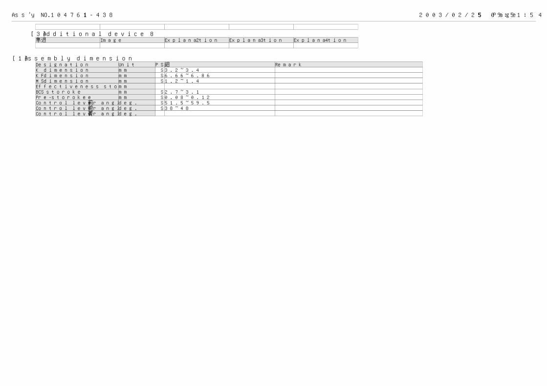
Ass'y NO. 104761-4381 2003/02/25 09:51:55 Page 4
[3] Additional device 8名称 Image Explanation 2 Explanation 3 Explanation 4
[1] Assembly dimensionDesignation Unit PSC 値 RemarkK dimension mm S 3.2~3.4KF dimension mm S 6.66~6.86MS dimension mm S 1.2~1.4Effectiveness storoke mm BCS storoke mm S 2.7~3.1Pre-storokee mm S 0.08~0.12Control lever angle α deg. S 51.5~59.5Control lever angle β deg. S 38~48Control lever angle γ deg.

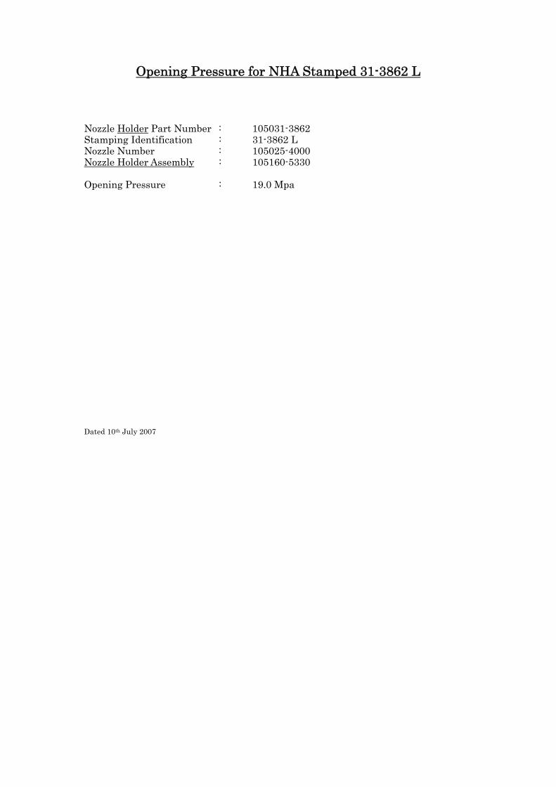
Opening Pressure for NHA Stamped 31-3862 L Nozzle Holder Part Number : 105031-3862 Stamping Identification : 31-3862 L Nozzle Number : 105025-4000 Nozzle Holder Assembly : 105160-5330 Opening Pressure : 19.0 Mpa
Dated 10th July 2007

Injector Number 31-3862 N
Nozzle & holder assembly no.: 105160-5420 Nozzle holder number: 105031-3862 Nozzle no.: 105025-4200 Opening pressure: 20.0 MPa
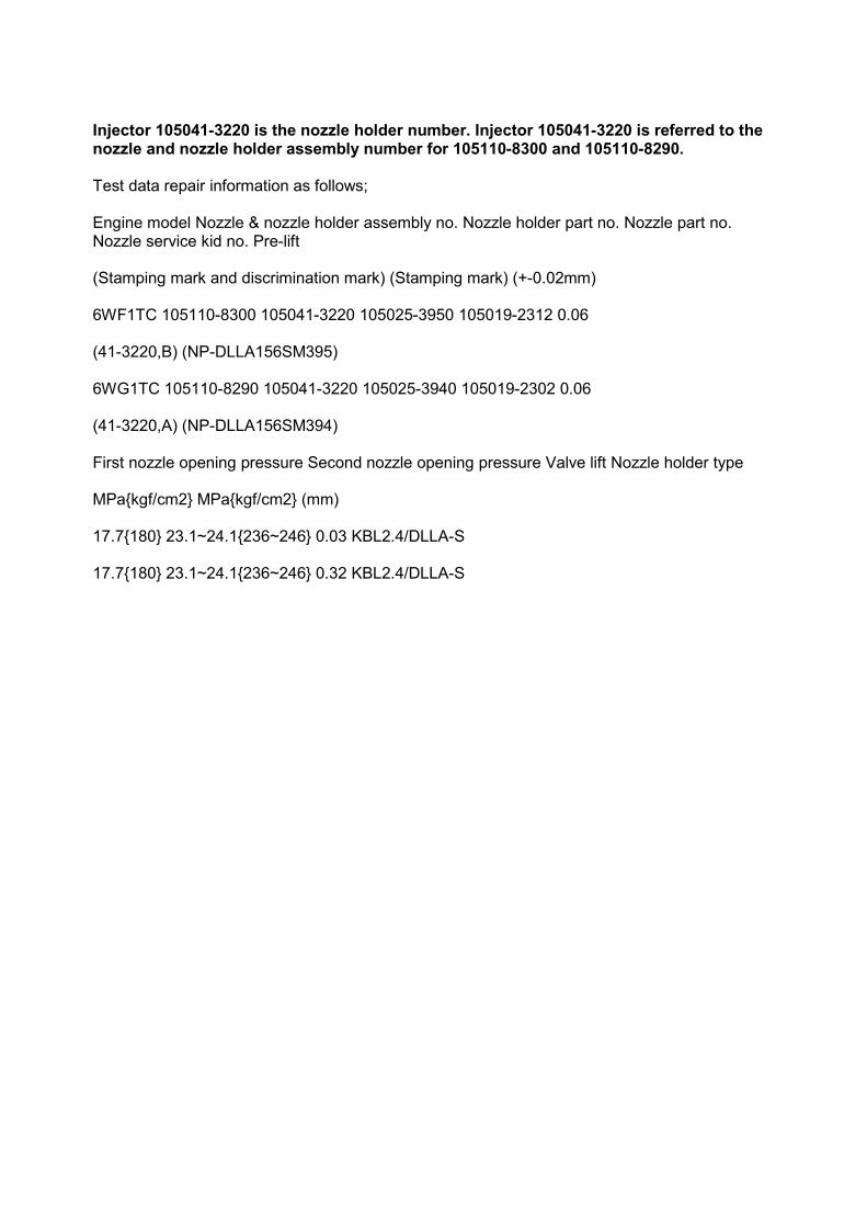
Injector 105041-3220 is the nozzle holder number. Injector 105041-3220 is referred to thenozzle and nozzle holder assembly number for 105110-8300 and 105110-8290.
Test data repair information as follows;
Engine model Nozzle & nozzle holder assembly no. Nozzle holder part no. Nozzle part no.Nozzle service kid no. Pre-lift
(Stamping mark and discrimination mark) (Stamping mark) (+-0.02mm)
6WF1TC 105110-8300 105041-3220 105025-3950 105019-2312 0.06
(41-3220,B) (NP-DLLA156SM395)
6WG1TC 105110-8290 105041-3220 105025-3940 105019-2302 0.06
(41-3220,A) (NP-DLLA156SM394)
First nozzle opening pressure Second nozzle opening pressure Valve lift Nozzle holder type
MPa{kgf/cm2} MPa{kgf/cm2} (mm)
17.7{180} 23.1~24.1{236~246} 0.03 KBL2.4/DLLA-S
17.7{180} 23.1~24.1{236~246} 0.32 KBL2.4/DLLA-S
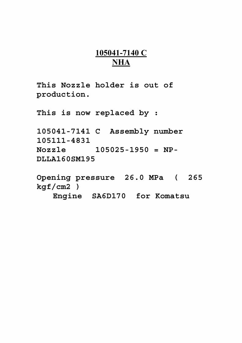
105041-7140 CNHA
This Nozzle holder is out ofproduction.
This is now replaced by :
105041-7141 C Assembly number105111-4831Nozzle 105025-1950 = NP-DLLA160SM195
Opening pressure 26.0 MPa ( 265kgf/cm2 )
Engine SA6D170 for Komatsu
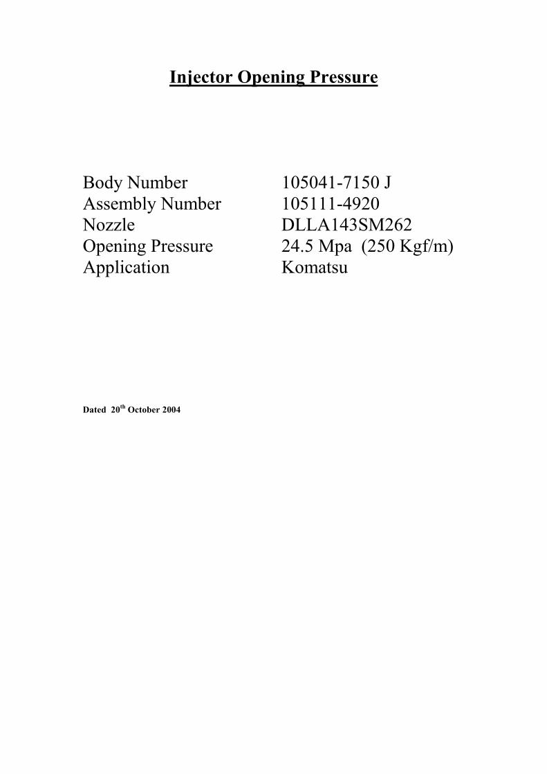
Injector Opening Pressure
Body Number 105041-7150 JAssembly Number 105111-4920Nozzle DLLA143SM262Opening Pressure 24.5 Mpa (250 Kgf/m)Application Komatsu
Dated 20th October 2004
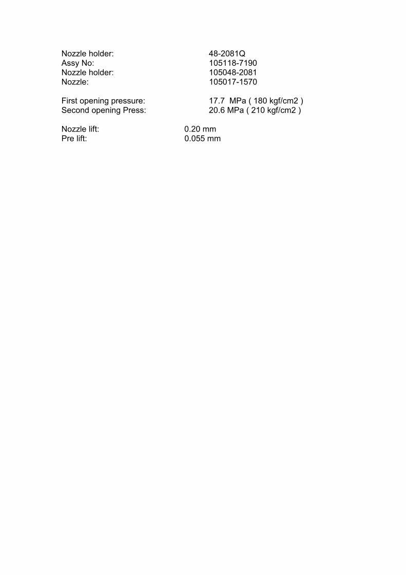
Nozzle holder: 48-2081QAssy No: 105118-7190Nozzle holder: 105048-2081Nozzle: 105017-1570
First opening pressure: 17.7 MPa ( 180 kgf/cm2 )Second opening Press: 20.6 MPa ( 210 kgf/cm2 )
Nozzle lift: 0.20 mmPre lift: 0.055 mm

NHA 105048-2270 G (Isuzu)
Opening Pressure for Test purposes only. This NHA is not serviceable in the field.
Assy No. 105118-8211 Nozzle No. 105017-3090 First nozzle opening pressure : 19.5 MPa Second nozzle opening pressure : 33.8 MPa Dated Dec 2005
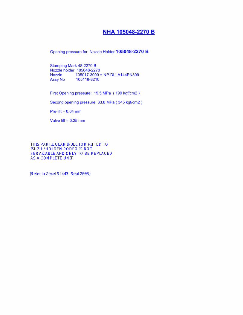
NHA 105048-2270 B
Opening pressure for Nozzle Holder 105048-2270 B
Stamping Mark 48-2270 BNozzle holder 105048-2270Nozzle 105017-3090 = NP-DLLA144PN309Assy No 105118-8210
First Opening pressure: 19.5 MPa ( 199 kgf/cm2 )
Second opening pressure 33.8 MPa ( 345 kgf/cm2 )
Pre-lift = 0.04 mm
Valve lift = 0.25 mm
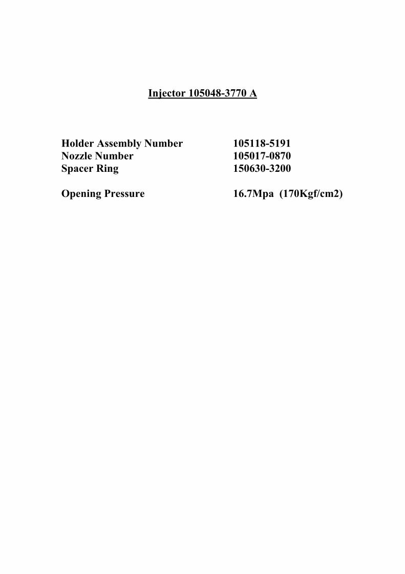
Injector 105048-3770 A
Holder Assembly Number 105118-5191Nozzle Number 105017-0870Spacer Ring 150630-3200
Opening Pressure 16.7Mpa (170Kgf/cm2)
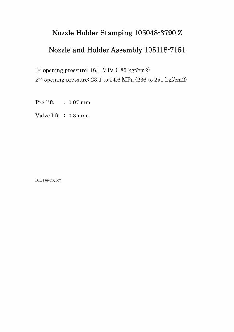
Nozzle Holder Stamping 105048-3790 Z
Nozzle and Holder Assembly 105118-7151
1st opening pressure: 18.1 MPa (185 kgf/cm2) 2nd opening pressure: 23.1 to 24.6 MPa (236 to 251 kgf/cm2)
Pre-lift : 0.07 mm Valve lift : 0.3 mm. Dated 09/01/2007
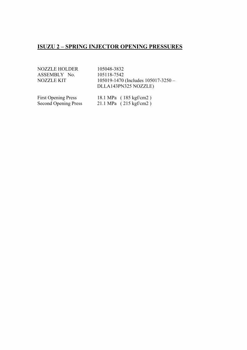
ISUZU 2 � SPRING INJECTOR OPENING PRESSURES
NOZZLE HOLDER 105048-3832ASSEMBLY No. 105118-7542NOZZLE KIT 105019-1470 (Includes 105017-3250 �
DLLA143PN325 NOZZLE)
First Opening Press 18.1 MPa ( 185 kgf/cm2 )Second Opening Press 21.1 MPa ( 215 kgf/cm2 )

105048-4120 (KBL 2.5P) NHA The Opening Pressures for the following Nozzle Holder Assemblies are listed for information purposes only. The NHA is only to be replaced as complete unit and please confirm application part number with OE (Nissan) before replacing NHA. These NHAs are not to be serviced in the field for the following reasons:- 1) Nozzle retaining nuts are fastened using special tightening machines. If tightened by hand using standard tools, damage will result. 2) The pre-lift is close to 0.03 mm. This cannot be measured using a dial gauge. It is measured using special device that measures oil flow. 3) Injection holes are extremely small (around 0.18 mm). Damage will result if work is not performed in a special clean room.
Holder Stamping Assembly Number
1 st Opening Pressure [Factory Setting]
2 nd Opening Pressure [Factory Setting]
48-4120 E 105118-7621 21.0 MPa (214 kgf/cm²)
[21.5-22.5 MPa (219-229 kgf/cm²)]
39.5 MPa (403 kgf/cm²) [40.0-41.5 MPa (408-423 Kgf/cm²)]
48-4120 S 48-4120 S or L
105118-7331 105118-7770
19.0 MPa (194 kgf/cm²) [19.5-20.5 MPa (199-209 kgf/cm²)]
37.5 MPa (382 kgf/cm²) [38.0-39.5 MPa (387-402 kgf/cm²)]
48-4120 T or U 105118-7911
19.0 MPa (194 kgf/cm²) [19.5-20.5 MPa (199-209 kgf/cm²)]
37.5 MPa (382 kgf/cm²) [37.8-39.8 MPa (385-405 kgf/cm²)]
48-4120 V or Z 48-4120 W or X
105118-8310 105118-8420
19.0 MPa (194 kgf/cm²) [19.5-20.5 MPa (199-209 kgf/cm²)]
37.5 MPa (382 kgf/cm²) [37.8-39.8 MPa (385-405 kgf/cm²)]
48-4120 H 48-4120 G
105118-7981 105118-7981
19.0 MPa (194 kgf/cm²) [19.5-20.5 MPa (199-209 kgf/cm²)] No test pressures available
37.5 MPa (382 kgf/cm²) [37.8-39.8 MPa (385-405 kgf/cm²)] No test pressures available
Dated 26th May 2006
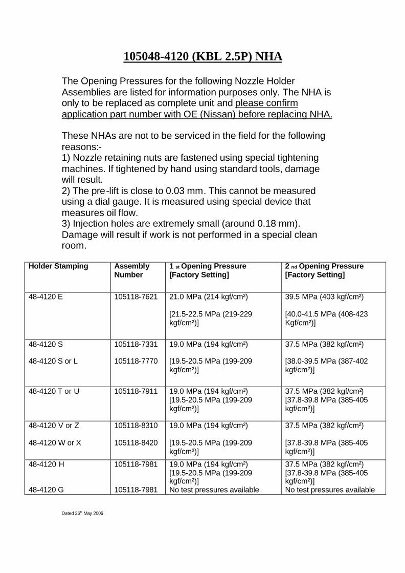
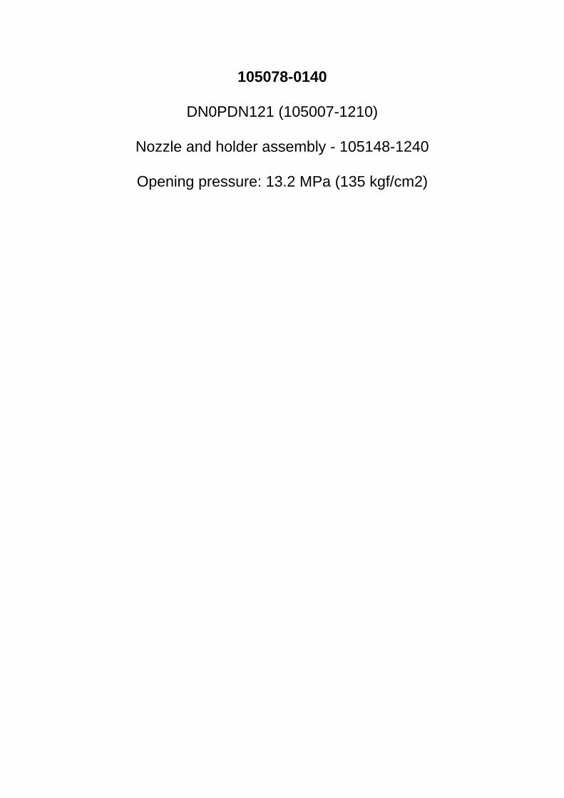
105078-0140
DN0PDN121 (105007-1210)
Nozzle and holder assembly - 105148-1240
Opening pressure: 13.2 MPa (135 kgf/cm2)
Injector 105041-3220 is the nozzle holder number. Injector 105041-3220 is refered to the nozzle and nozzle holder assembly number for 105110-8300 and 105110-8290.
Test data repair information
Engine model Nozzle & nozzle holder assembly no. Nozzle holder part no. Nozzle part no. Nozzle service kit no. Pre-lift(Stamping mark and discrimination mark)
6WF1TC 105110-8300 105041-3220 105025-3950 105019-2312 0.06(41-3220,B) (NP-DLLA156SM395) (+-0.02mm)
6WG1TC 105110-8290 105041-3220 105025-3940 105019-2302 0.06(41-3220,A) (NP-DLLA156SM394) (+-0.02mm)
First nozzle opening pressure Second nozzle opening pressure Valve lift Nozzle holder typeMPa{kgf/cm2} MPa{kgf/cm2} (mm)17.7{180} 23.1~24.1{236~246} 0.3 KBL2.4/DLLA-S
17.7{180} 23.1~24.1{236~246} 0.32 KBL2.4/DLLA-S
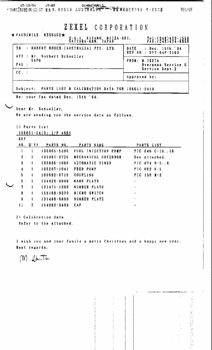
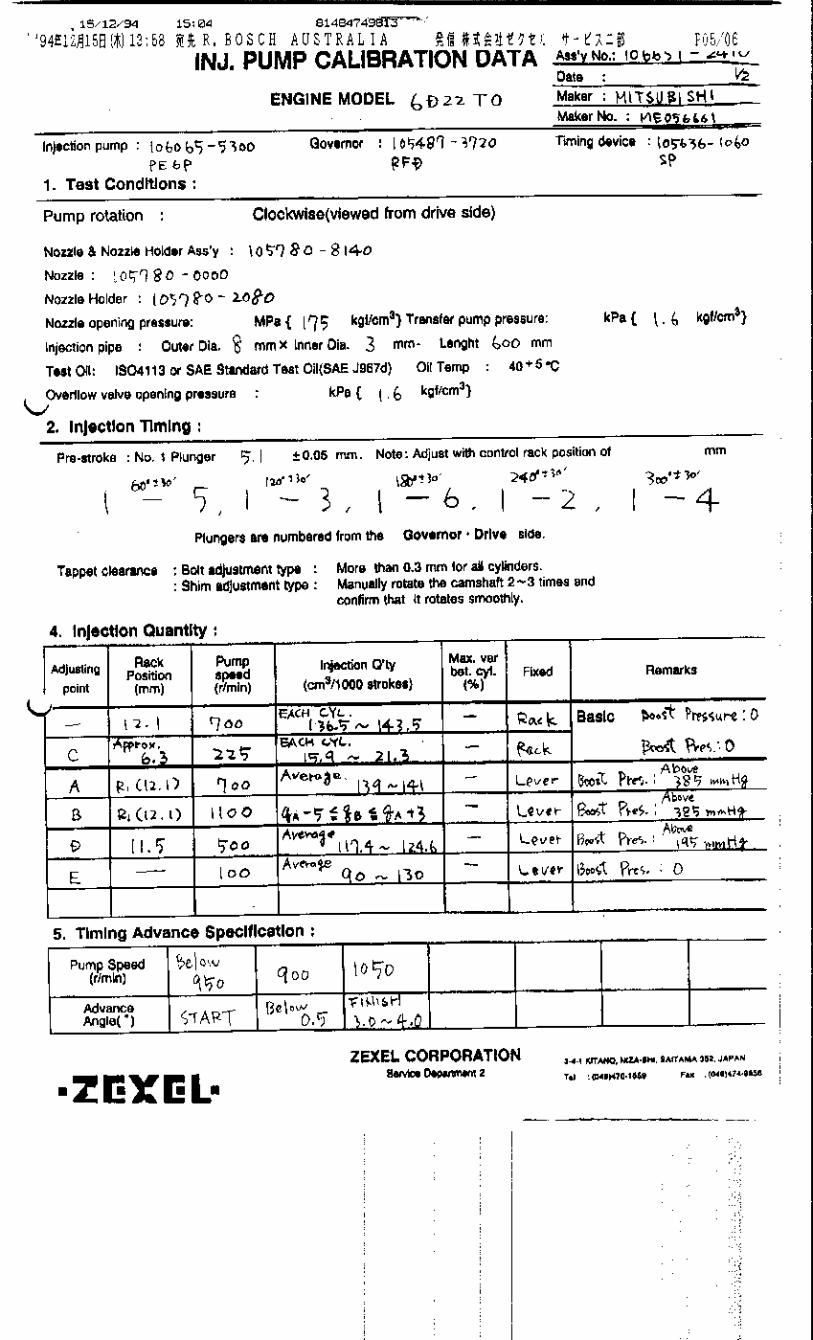
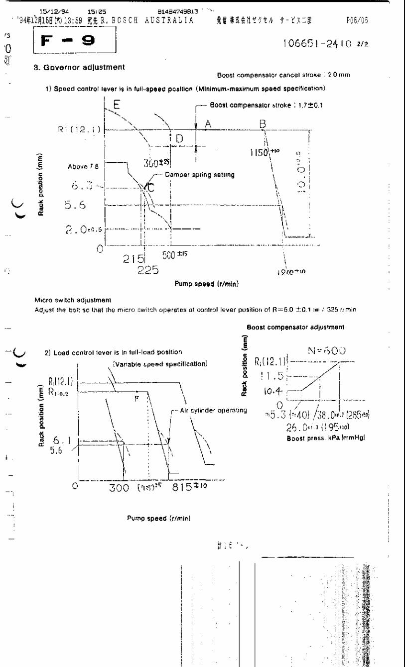
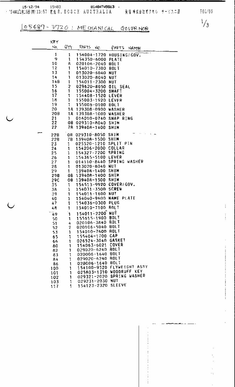

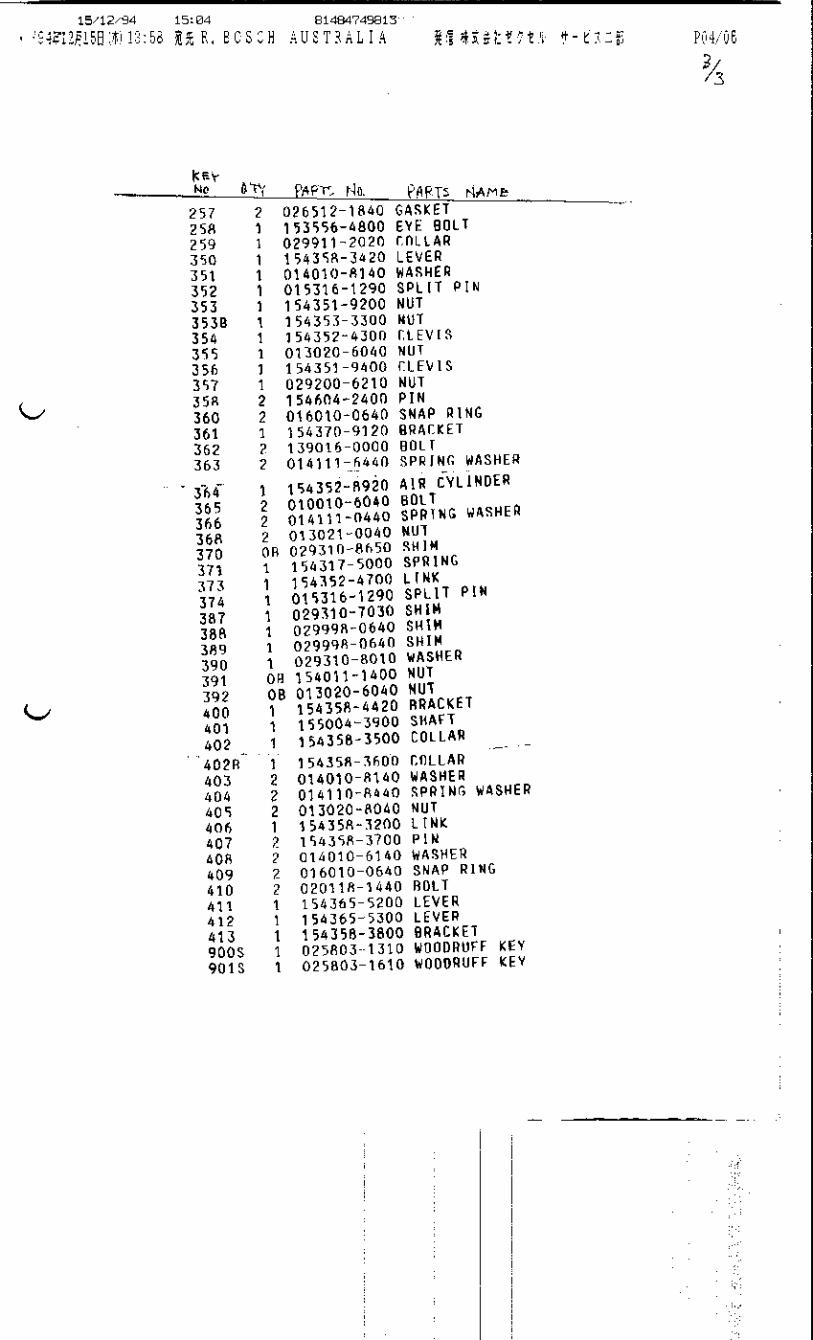

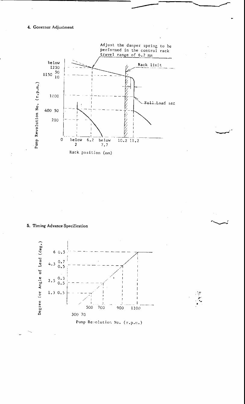


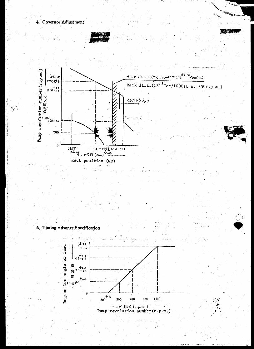


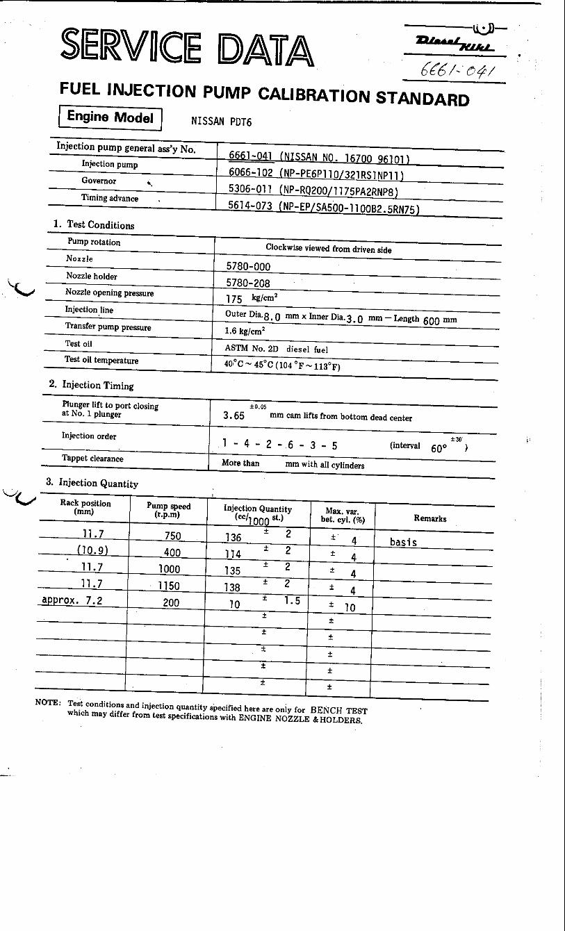
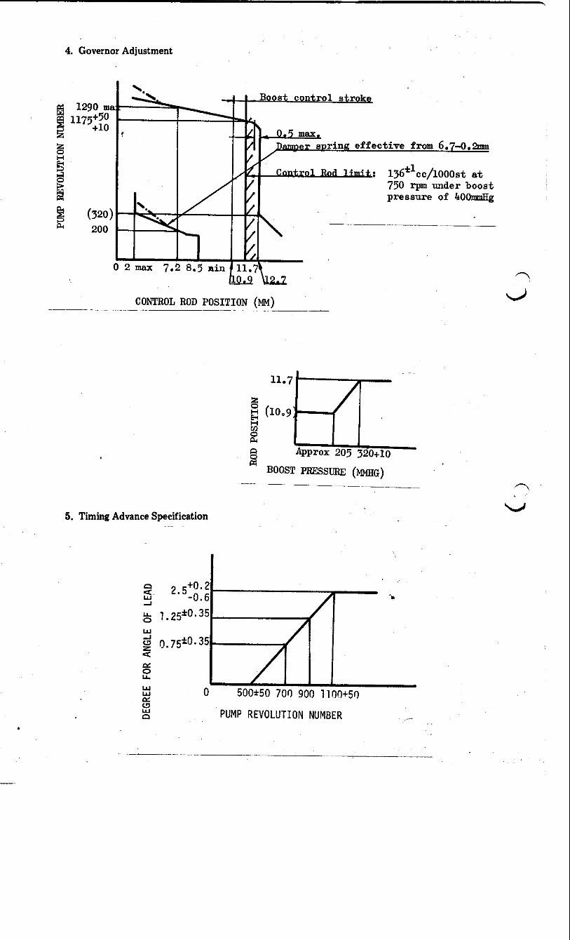
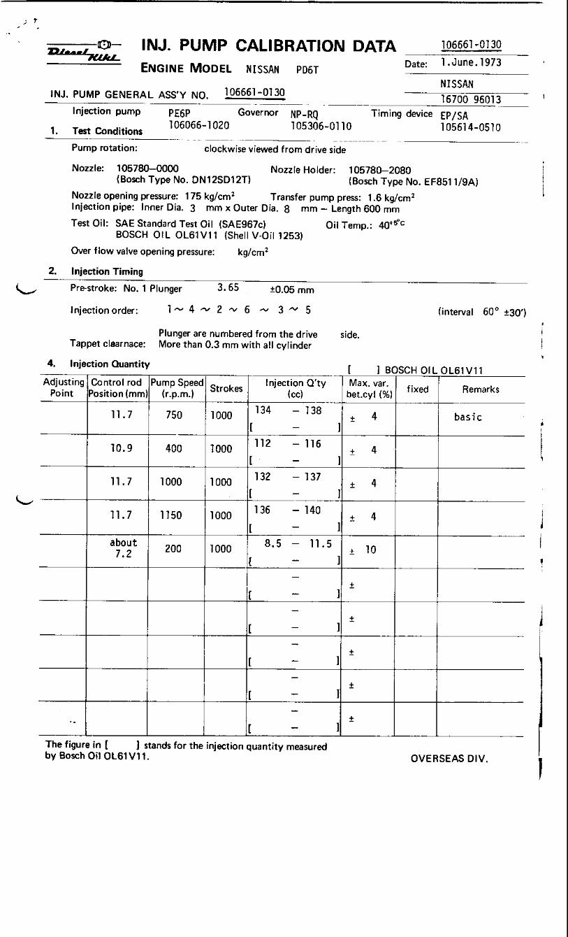
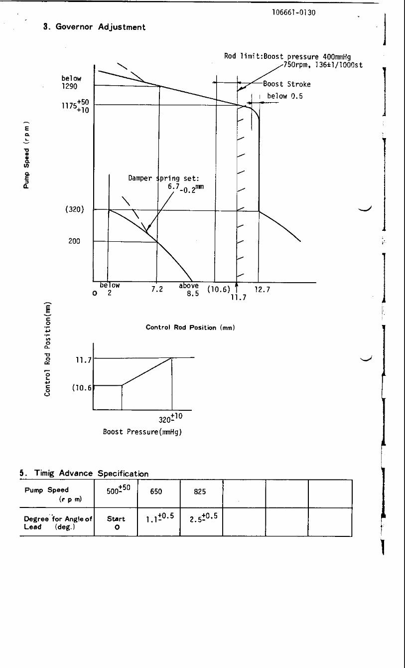
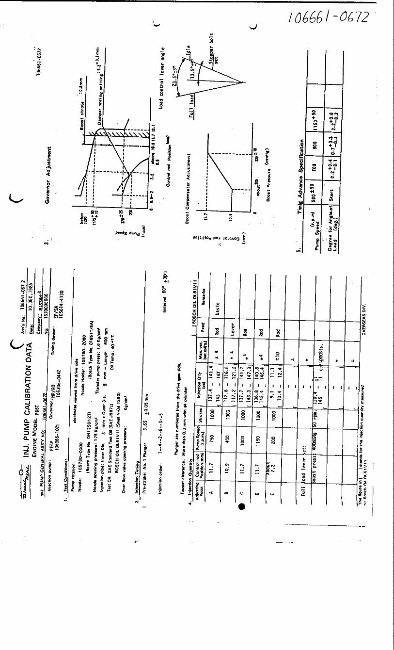
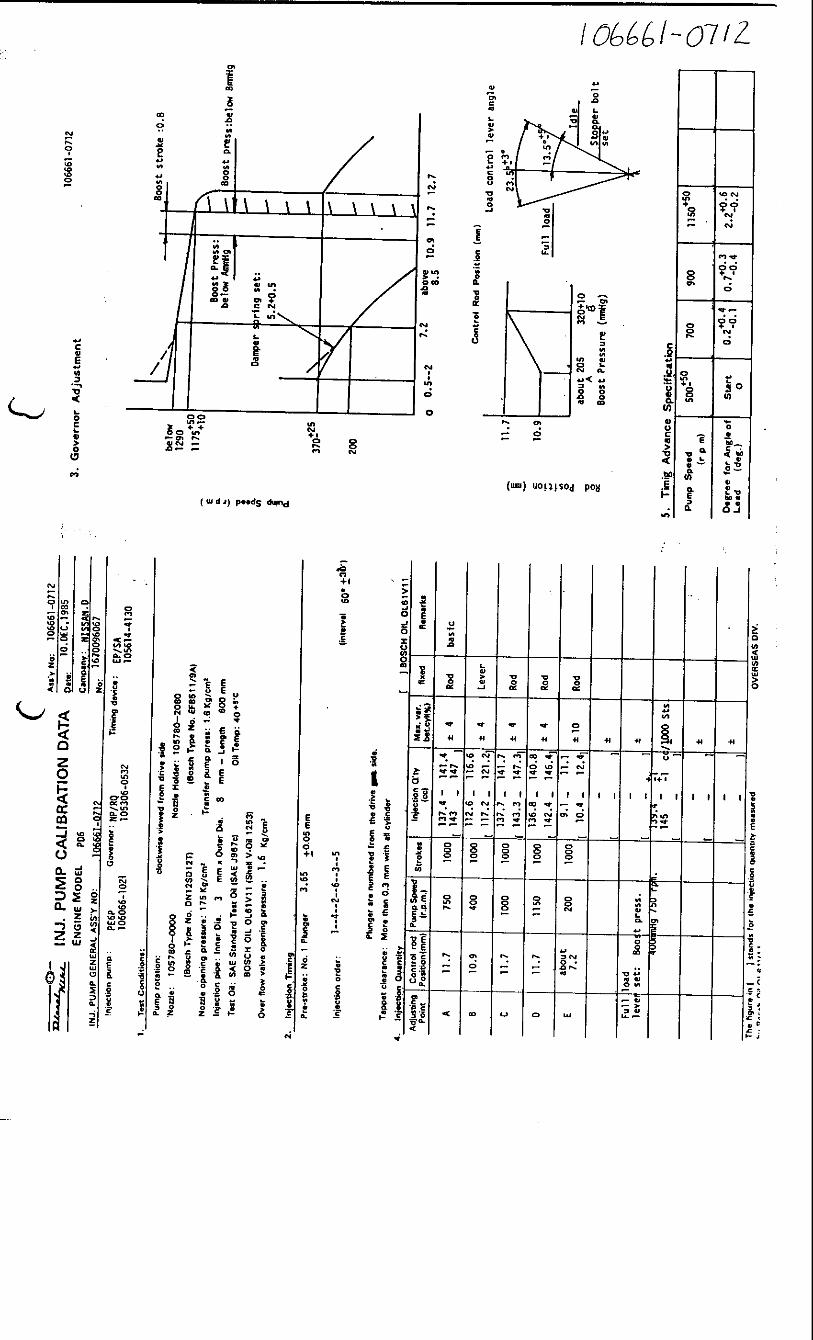
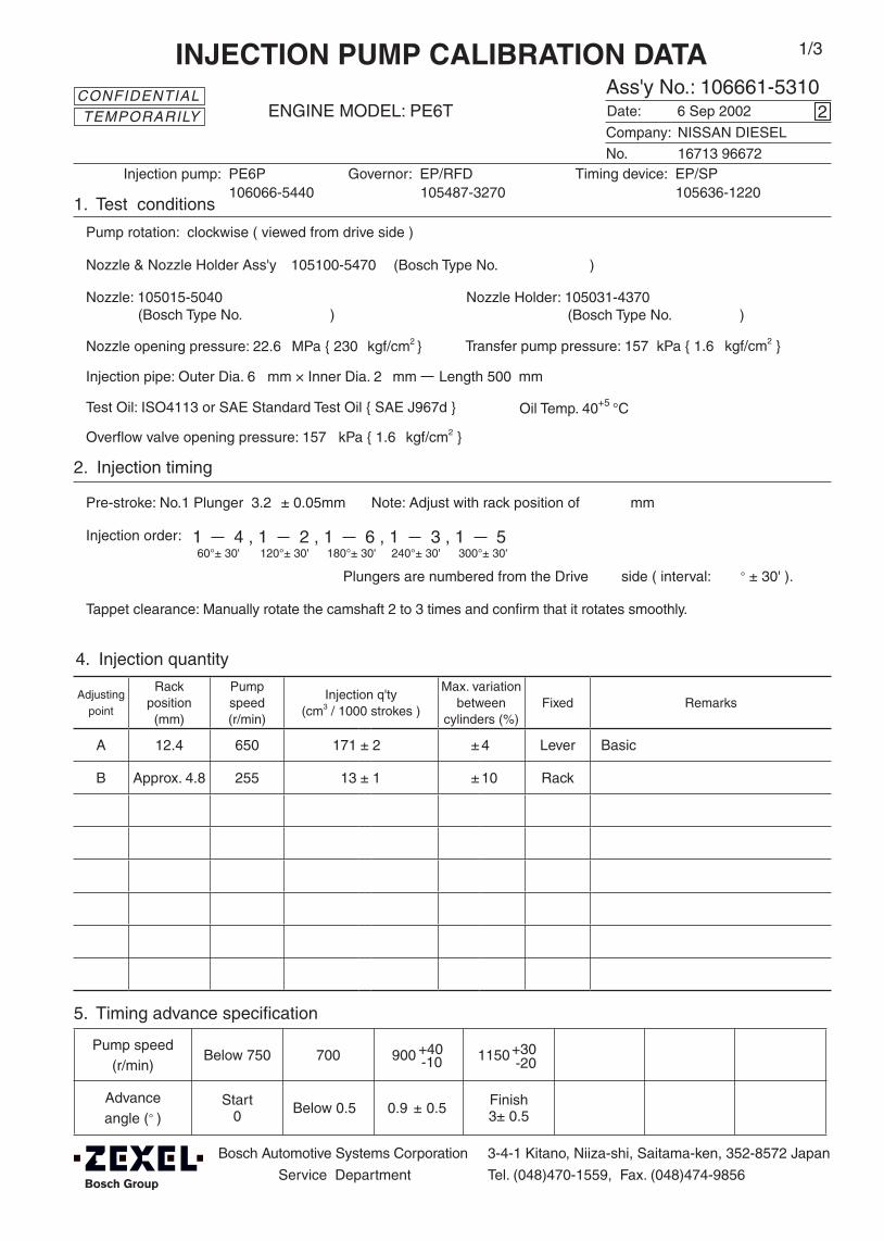
Adjustingpoint
Rackposition
(mm)
Pumpspeed(r/min)
Injection q'ty(cm3 / 1000 strokes )
Max. variationbetween
cylinders (%)Fixed Remarks
A 12.4 650 171 ± 2 ± 4 Lever Basic
B Approx. 4.8 255 13 ± 1 ± 10 Rack
Injection order:
Pump speed(r/min)
Below 750 700 900 1150
Advanceangle (° )
Start0 Below 0.5 0.9 ± 0.5 Finish
3± 0.5
4. Injection quantity
5. Timing advance specification
Bosch Automotive Systems Corporation
Service Department
3-4-1 Kitano, Niiza-shi, Saitama-ken, 352-8572 Japan
Tel. (048)470-1559, Fax. (048)474-9856
Company:
Ass'y No.: 106661-5310ENGINE MODEL: PE6T
No. Governor: EP/RFD Timing device: EP/SP
1. Test conditions
Date:
Pump rotation: clockwise ( viewed from drive side )
Injection pump: PE6P105487-3270 105636-1220
kgf/cm2 }
2. Injection timing
Pre-stroke: No.1 Plunger 3.2 ± 0.05mm mm
Plungers are numbered from the Drive ° ± 30' ).
CONFIDENTIAL
INJECTION PUMP CALIBRATION DATA
6 Sep 2002
NISSAN DIESEL
16713 96672
106066-5440
Injection pipe: Outer Dia. 6 mm × Inner Dia. 2 mm Length 500 mm
Nozzle opening pressure: 22.6 MPa { 230 kgf/cm2 }
Nozzle: 105015-5040 Nozzle Holder: 105031-4370(Bosch Type No. ) (Bosch Type No. )
Nozzle & Nozzle Holder Ass'y: 105100-5470 (Bosch Type No. )
Overflow valve opening pressure: 157 kPa { 1.6 kgf/cm2 }
Test Oil: ISO4113 or SAE Standard Test Oil { SAE J967d } Oil Temp. 40+5 °C
side ( interval:
2
Transfer pump pressure: 157 kPa { 1.6
Note: Adjust with rack position of
1 4 , 1 2 , 1 6 , 1 3 , 1 560°± 30' 120°± 30' 180°± 30' 240°± 30' 300°± 30'
1/3
Tappet clearance: Manually rotate the camshaft 2 to 3 times and confirm that it rotates smoothly.
TEMPORARILY
(qA-27 qB qA-19)
+30-20-10
+40

106661-5310 2/3
3. Governor adjustment
Above 6.3
0 255 Below 1250
A
B
Rac
k po
sitio
n (m
m)
Pump speed (r/min)
Rack limit using stop lever
12.6+0.2
0.9±0.5
4.8
465±15
11.5
Damper spring setting: 4.8-0.2
12.4
1150+20
4.8
2800
Variable speed specification at idle setting
Main spring setting
Pump speed (r/min)
Rac
k po
sitio
n (m
m)
Perform idle sub-spring adjustment when necessary.
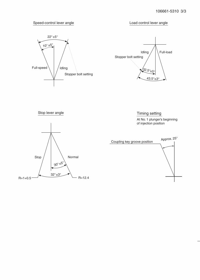
106661-5310 3/3
32.5°±5°
Speed-control lever angle
Idling
Stopper bolt setting
Stop lever angle
R=1+0.5
Stop
Full-speed
Normal
22°±5°
10° ±5°
Coupling key groove position
Load control lever angle
Full-load
Stopper bolt setting
Idling
43.5°±3°
32°±3°
30°±5°
Timing setting
At No. 1 plunger’s beginning of injection position
Approx. 25°
R=12.4
Oil temperature: 40+5 °C
BOSCH K.K.Sales Automotive Aftermarket Division
3-4-1 Kitano, Niiza-shi, Saitama-ken, 352-8572, JAPAN
Tel. 81-48-475-2521 Fax. 81-48-475-2520
Adjustingpoint
Rackposition
(mm)
Pumpspeed(r/min)
Injection quantity(cm3/1000 strokes)
Max. variationbetween
cylinders (%)Fixed Remarks
A 11.7 750 146 ± 2 ± 4 Lever Basic
B 9.7 300 88 ± 3 ± 4 Lever
C Approx 6.4 240 10 ± 1 ± 10 Rack
Injection order:
Pump speed(r/min)
700+50 900 1150
Advanceangle (° )
Below 0.5 0.9 ± 0.5 Finish
3.0±0.5
4. Injection quantity
5. Timing advance specification
Company:
Assy No.: 106661-5541ENGINE MODEL: PE6T
No. Governor: EP/RFD-B Timing device: EP/SA
1. Test conditions
Date:
Pump rotation: clockwise (viewed from drive side)
Injection pump: PE6P105487-5771 105614-4220
kgf/cm2}
2. Injection timing
Pre-stroke: No.1 plunger 3.2 ± 0.05mm mm
Plungers are numbered from the Drive ° ± 30').
CONFIDENTIAL
INJECTION PUMP CALIBRATION DATA
9 Feb 2004
NISSAN DIESEL
16713 96902
106066-1191
Injection pipe: outer dia.6 mm × inner dia. 2 mm length 500 mm
Nozzle opening pressure: 22.6 MPa {230 kgf/cm2}
Nozzle: 105015-4170 Nozzle holder: 105031-4370(Bosch type no. DLLA137S374N417) (Bosch type no. )
Nozzle & nozzle holder assy: 105100-4570 (Bosch type no. )
Test oil: ISO4113 or SAE standard test oil {SAE J967d}
side (interval:
4
Transfer pump pressure: 157 kPa {1.6
Note: Adjust with rack position of
1 4 , 1 2 , 1 6 , 1 3 , 1 560°± 30' 120°± 30' 180°± 30' 240°± 30' 300°± 30'
1/3
Tappet clearance: Manually rotate the camshaft 2 to 3 times and confirm that it rotates smoothly.
Overflow valve opening pressure: 157 ± 34 kPa {1.6 ± 0.35 kgf/cm2}
Boost press. kPa {mmHg}Above 66.7 {Above 500}
Boost press. 0
TEMPORARILY
Boost press. 0
+40-10
+30-20

106661-5541 2/3
3. Governor adjustment
Above 8.7
0
Below (150)
1205
A
C
Rac
k po
sitio
n (m
m)
Pump speed (r/min)
Rack limit using stop lever
1.7
9.7
(500)
10.5
+0.
5Damper spring setting
12.7
(1150)
6.4
2600
Variable speed specification at idle setting
Main spring setting
Pump speed (r/min)
Rac
k po
sitio
n (m
m)
B
Boost compensator stroke:2.0±0.1 mm
11.711.2±0.1
6.4±2.06.44.1
2.2±0.3
240
430 485 1175
11.7
9.7
0
4.0+2.0 {30+15}
53.3-13.3 {400-100}
N = 300
Rac
k po
sitio
n (m
m)
Boost pressure kPa {mmHg}
Boost compensator adjustment

106661-5541 3/3
Stopper bolt setting
Stop lever angle
Stop Normal
Drive side
Idling
Speed-control lever angle
Full-speed
(24°) ±5°
13° ±5°
Idling
40.5° ±3°
28.5°±5°
Full-load
Load-control lever angle
Stopper bolt setting
28°±5°
30°±5° R=11.7
Coupling key groove position
Timing setting
At No. 1 plunger’s beginning of injection position
Approx. 30°
R=1.5±0.1
N=260

Oil temperature: 40+5 °C
BOSCH K.K.Sales Automotive Aftermarket Division
3-4-1 Kitano, Niiza-shi, Saitama-ken, 352-8572, JAPAN
Tel. 81-48-475-2521 Fax. 81-48-475-2520
Adjustingpoint
Rackposition
(mm)
Pumpspeed(r/min)
Injection quantity(cm3/1000 strokes)
Max. variationbetween
cylinders (%)Fixed Remarks
A 11.7 750 146 ± 2 ± 4 Lever Basic
B 9.7 300 88 ± 3 ± 4 Lever
C Approx 6.4 240 10 ± 1 ± 10 Rack
Injection order:
Pump speed(r/min)
700+50 900 1150
Advanceangle (° )
Below 0.5 0.9 ± 0.5 Finish
3.0±0.5
4. Injection quantity
5. Timing advance specification
Company:
Assy No.: 106661-5541ENGINE MODEL: PE6T
No. Governor: EP/RFD-B Timing device: EP/SA
1. Test conditions
Date:
Pump rotation: clockwise (viewed from drive side)
Injection pump: PE6P105487-5771 105614-4220
kgf/cm2}
2. Injection timing
Pre-stroke: No.1 plunger 3.2 ± 0.05mm mm
Plungers are numbered from the Drive ° ± 30').
CONFIDENTIAL
INJECTION PUMP CALIBRATION DATA
9 Feb 2004
NISSAN DIESEL
16713 96902
106066-1191
Injection pipe: outer dia.6 mm × inner dia. 2 mm length 500 mm
Nozzle opening pressure: 22.6 MPa {230 kgf/cm2}
Nozzle: 105015-4170 Nozzle holder: 105031-4370(Bosch type no. DLLA137S374N417) (Bosch type no. )
Nozzle & nozzle holder assy: 105100-4570 (Bosch type no. )
Test oil: ISO4113 or SAE standard test oil {SAE J967d}
side (interval:
4
Transfer pump pressure: 157 kPa {1.6
Note: Adjust with rack position of
1 4 , 1 2 , 1 6 , 1 3 , 1 560°± 30' 120°± 30' 180°± 30' 240°± 30' 300°± 30'
1/3
Tappet clearance: Manually rotate the camshaft 2 to 3 times and confirm that it rotates smoothly.
Overflow valve opening pressure: 157 ± 34 kPa {1.6 ± 0.35 kgf/cm2}
Boost press. kPa {mmHg}Above 66.7 {Above 500}
Boost press. 0
TEMPORARILY
Boost press. 0
+40-10
+30-20
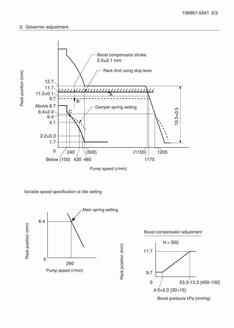
106661-5541 2/3
3. Governor adjustment
Above 8.7
0
Below (150)
1205
A
C
Rac
k po
sitio
n (m
m)
Pump speed (r/min)
Rack limit using stop lever
1.7
9.7
(500)
10.5
+0.
5Damper spring setting
12.7
(1150)
6.4
2600
Variable speed specification at idle setting
Main spring setting
Pump speed (r/min)
Rac
k po
sitio
n (m
m)
B
Boost compensator stroke:2.0±0.1 mm
11.711.2±0.1
6.4±2.06.44.1
2.2±0.3
240
430 485 1175
11.7
9.7
0
4.0+2.0 {30+15}
53.3-13.3 {400-100}
N = 300
Rac
k po
sitio
n (m
m)
Boost pressure kPa {mmHg}
Boost compensator adjustment
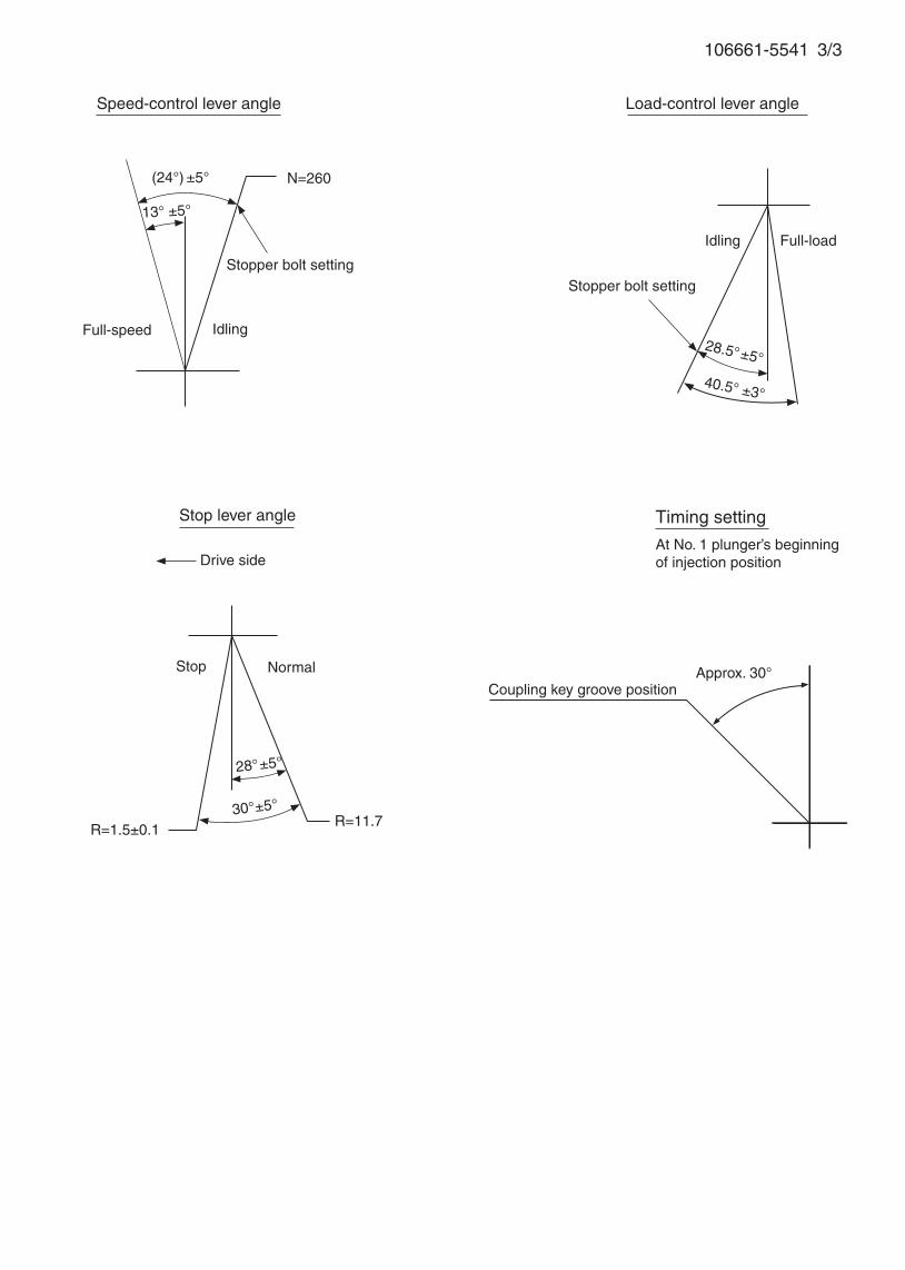
106661-5541 3/3
Stopper bolt setting
Stop lever angle
Stop Normal
Drive side
Idling
Speed-control lever angle
Full-speed
(24°) ±5°
13° ±5°
Idling
40.5° ±3°
28.5°±5°
Full-load
Load-control lever angle
Stopper bolt setting
28°±5°
30°±5° R=11.7
Coupling key groove position
Timing setting
At No. 1 plunger’s beginning of injection position
Approx. 30°
R=1.5±0.1
N=260


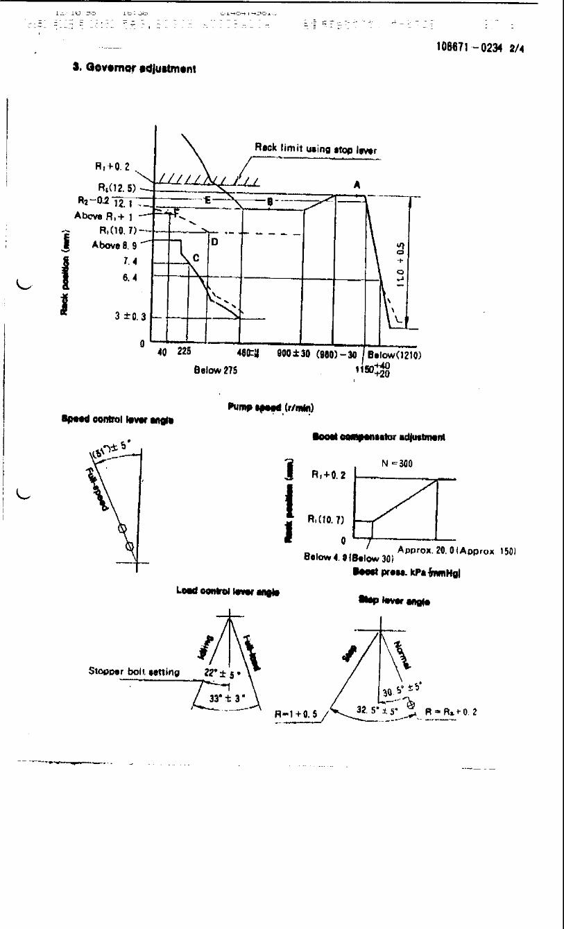
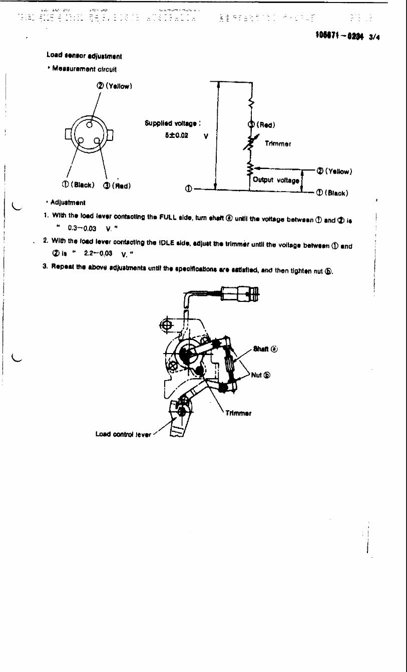
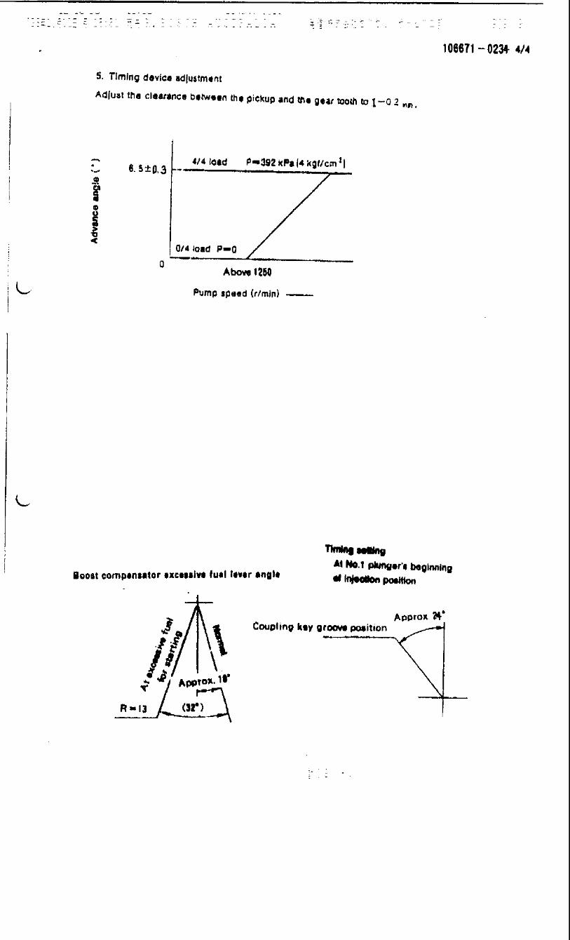
Adjustingpoint
Rackposition
(mm)
Pumpspeed(r/min)
Injection q'ty(cm3 / 1000 strokes )
Max. variationbetween
cylinders (%)Fixed Remarks
A 11.9 600 203 ± 2 ± 4 Lever Basic
C Approx 7.2 225 15 ± 1 ± 10 Rack
D 9.7 300 130 ± 2 - Lever
Injection order:
Pump speed(r/min)
Advanceangle (° )
4. Injection quantity
5. Timing advance specification
Bosch Automotive Systems Corporation
Service Department
3-4-1 Kitano, Niiza-shi, Saitama-ken, 352-8572 Japan
Tel. (048)470-1559, Fax. (048)474-9856
Company:
Ass'y No.: 106671-0620ENGINE MODEL: PF6TB
No. Governor: EP/RFD Timing device: EP/SPGH
1. Test conditions
Date:
Pump rotation: clockwise ( viewed from drive side )
Injection pump: PE6P105487-3680 105691-3270
kgf/cm2 }
2. Injection timing
Pre-stroke: No.1 Plunger 3.9 ± 0.05mm mm
Plungers are numbered from the Drive ° ± 30' ).
CONFIDENTIAL
INJECTION PUMP CALIBRATION DATA
17 Jun 2002
NISSAN DIESEL
16800-96577
106060-7790
Injection pipe: Outer Dia. 6 mm × Inner Dia. 2.2mm Length 500 mm
Nozzle opening pressure: 17.7 MPa { 180 kgf/cm2 }
Nozzle: 105015-7350 Nozzle Holder: 105031-4630(Bosch Type No. ) (Bosch Type No. )
Nozzle & Nozzle Holder Ass'y: 105100-7470 (Bosch Type No. )
Overflow valve opening pressure: 157 kPa { 1.6 kgf/cm2 }
Test Oil: ISO4113 or SAE Standard Test Oil { SAE J967d } Oil Temp. 40+5 °C
side ( interval:
1
Transfer pump pressure: 157 kPa { 1.6
Note: Adjust with rack position of
1 4 , 1 2 , 1 6 , 1 3 , 1 560°± 30' 120°± 30' 180°± 30' 240°± 30' 300°± 30'
1/4
Tappet clearance: Manually rotate the camshaft 2 to 3 times and confirm that it rotates smoothly.
Boost press. kPa {mmHg}Above 76.0 {Above 570}
Boost press. 0
Rack limit
TEMPORARILY
Boost press. 0
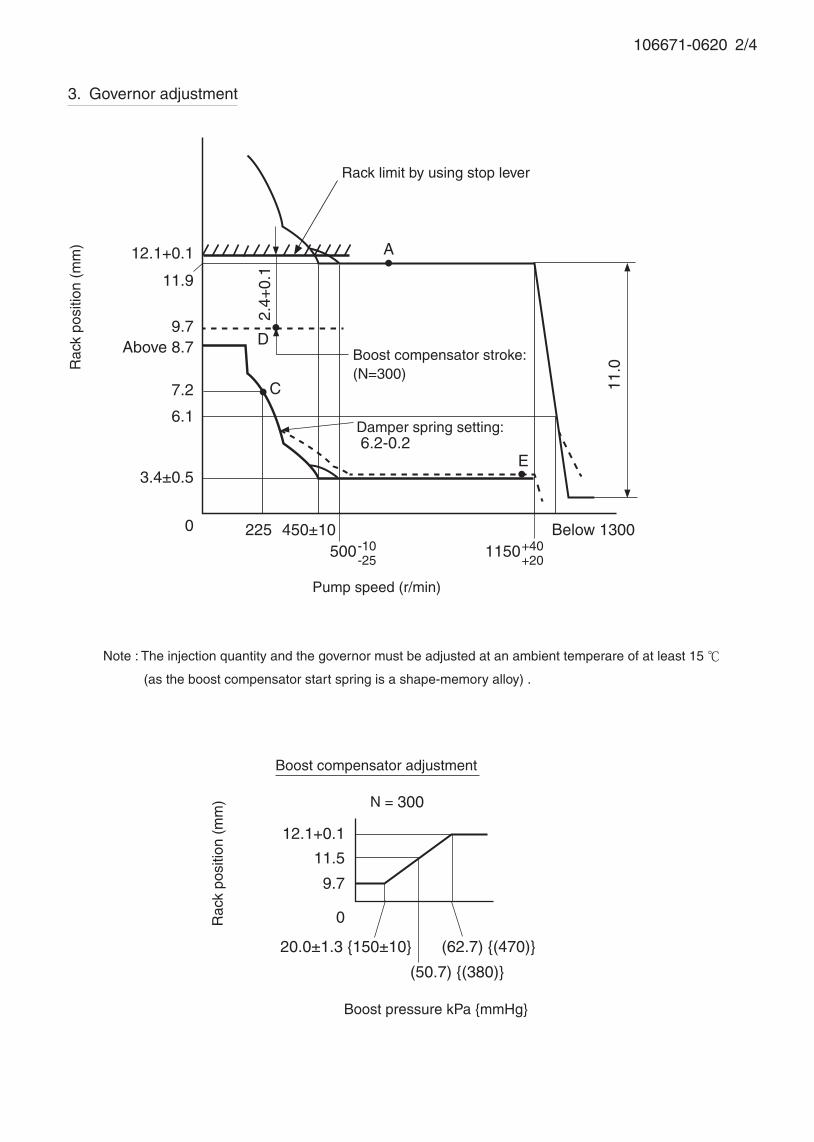
3. Governor adjustment
106671-0620 2/4
Above 8.7
0 225 Below 1300
A
C
Rac
k po
sitio
n (m
m)
Pump speed (r/min)
Rack limit by using stop lever
Boost compensator stroke:(N=300)
12.1+0.1
11.9
3.4±0.5
9.7
7.2
6.1
450±10
11.0
500-10-25
1150+40+20
D
E
Damper spring setting: 6.2-0.2
2.4+
0.1
12.1+0.1
0
20.0±1.3 {150±10} (62.7) {(470)}
N = 300
11.5
9.7
(50.7) {(380)}
Rac
k po
sitio
n (m
m)
Boost pressure kPa {mmHg}
Boost compensator adjustment
Note : The injection quantity and the governor must be adjusted at an ambient temperare of at least 15
(as the boost compensator start spring is a shape-memory alloy) .
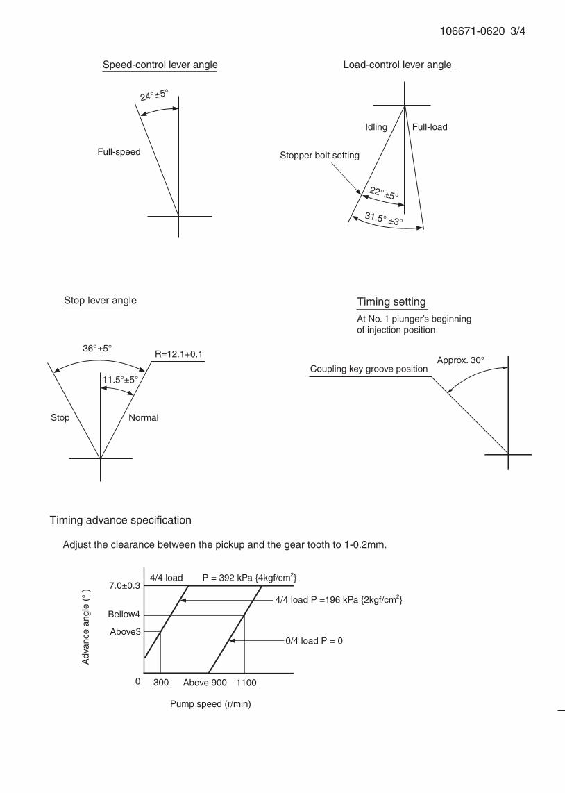
106671-0620 3/4
Speed-control lever angle
Idling
Stop lever angle
Stop
Full-speed
Normal
Coupling key groove position
Timing setting
At No. 1 plunger’s beginning of injection position
Approx. 30°
31.5° ±3°
22°±5°
R=12.1+0.1
Full-load
24°±5°
Load-control lever angle
Stopper bolt setting
36°±5°
11.5°±5°
300
Timing advance specification
Pump speed (r/min)
7.0±0.3
0 Above 900
0/4 load P = 0
4/4 load P = 392 kPa {4kgf/cm2}
Adv
ance
ang
le (
° )
Adjust the clearance between the pickup and the gear tooth to 1-0.2mm.
1100
4/4 load P =196 kPa {2kgf/cm2}
Above3
Bellow4
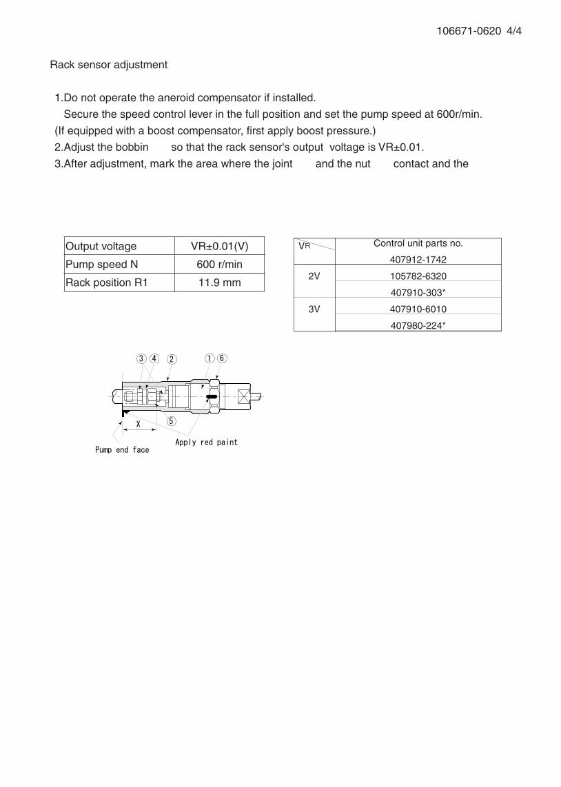
106671-0620 4/4
Rack sensor adjustment
1.Do not operate the aneroid compensator if installed.
Secure the speed control lever in the full position and set the pump speed at 600r/min.
(If equipped with a boost compensator, first apply boost pressure.)
2.Adjust the bobbin ① so that the rack sensor's output voltage is VR±0.01.
3.After adjustment, mark the area where the joint ② and the nut ③ contact and the area where
the joint ② and the pump housing contact with red paint.
VR Control unit parts no.
407912-1742
2V 105782-6320
407910-303*
3V 407910-6010
407980-224*
Output voltage VR±0.01(V)
Pump speed N 600 r/min
Rack position R1 11.9 mm
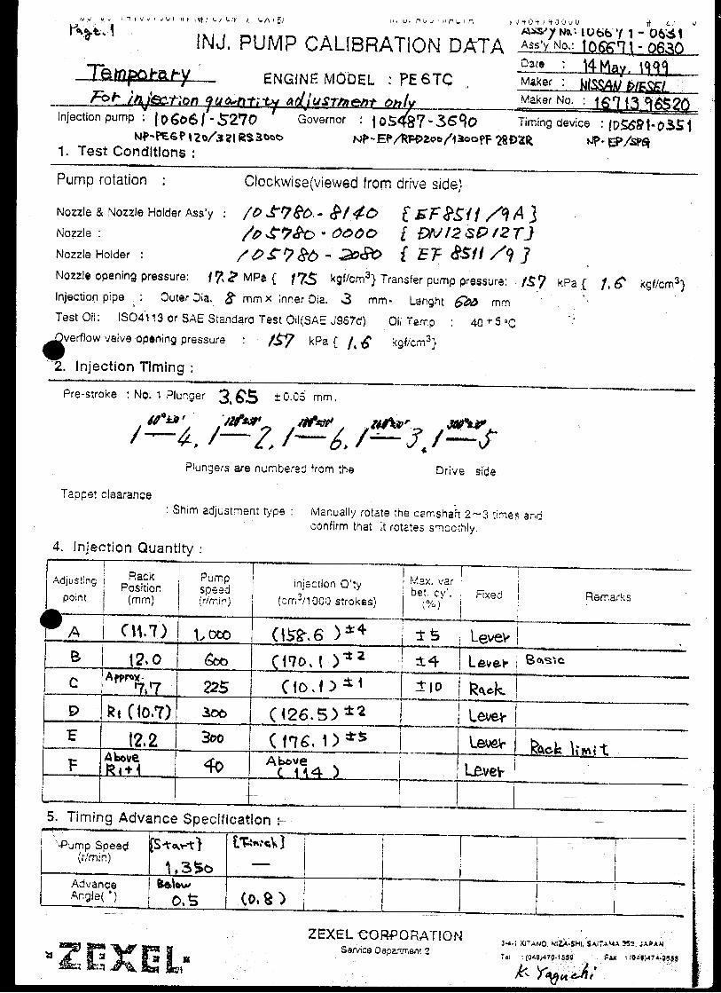


Oil temperature: 40+5 °C
BOSCH K.K.Sales Automotive Aftermarket Division
3-4-1 Kitano, Niiza-shi, Saitama-ken, 352-8572, JAPAN
Tel. 81-48-475-2521 Fax. 81-48-475-2520
Adjustingpoint
Rackposition
(mm)
Pumpspeed(r/min)
Injection quantity(cm3/1000 strokes)
Max. variationbetween
cylinders (%)Fixed Remarks
A 12.1 600 170 ± 2 ± 4 Lever Basic
B 12.1 1100 (164.6) ± 3 ± 5 Lever
C 10.4 300 114 ± 2 - Lever
D 12.4±0.1 300 (173) ± 5 - Lever
E Approx 8.0 250 16 ± 1 ± 10 Rack
Injection order:
Pump speed(r/min)
Below 875 825 925
Advanceangle (° )
Start
0 Below 0.5
Finish
1±0.5
4. Injection quantity
6. Timing advance specification
Company:
Assy No.: 106671-0830ENGINE MODEL: PE6TC
No. Governor: EP/RFD-D Timing device: EP/SP
1. Test conditions
Date:
Pump rotation: clockwise (viewed from drive side)
Injection pump: PE6P105487-4580 105636-1810
kgf/cm2}
2. Injection timing
Pre-stroke: No.1 plunger 3.65 ± 0.05mm mm
Plungers are numbered from the Drive ° ± 30').
CONFIDENTIAL
INJECTION PUMP CALIBRATION DATA
27 Sep 2004
NISSAN DIESEL
16713 96818
106061-5300
Injection pipe: outer dia. 6 mm × inner dia. 2 mm length 500 mm
Nozzle opening pressure: 22.6 MPa {230 kgf/cm2}
Nozzle: 105015-6340 Nozzle holder: 105031-4370(Bosch type no. DLLA140SN634) (Bosch type no. EF8511/9)
Nozzle & nozzle holder assy: 105101-5600 (Bosch type no. )
Test oil: ISO4113 or SAE standard test oil {SAE J967d}
side (interval:
1
Transfer pump pressure: 157 kPa {1.6
Note: Adjust with rack position of
1 4 , 1 2 , 1 6 , 1 3 , 1 560°± 30' 120°± 30' 180°± 30' 240°± 30' 300°± 30'
1/4
Tappet clearance: Manually rotate the camshaft 2 to 3 times and confirm that it rotates smoothly.
Boost pressure kPa {mmHg}Above 29.3 {Above 220}
Overflow valve opening pressure: 157 ± 34 kPa {1.6 ± 0.35 kgf/cm2}
Boost press. 0
TEMPORARILY
Boost pressure kPa {mmHg}Above 29.3 {Above 220}
Boost pressure kPa {mmHg}Above 29.3 {Above 220}
Boost press. 0
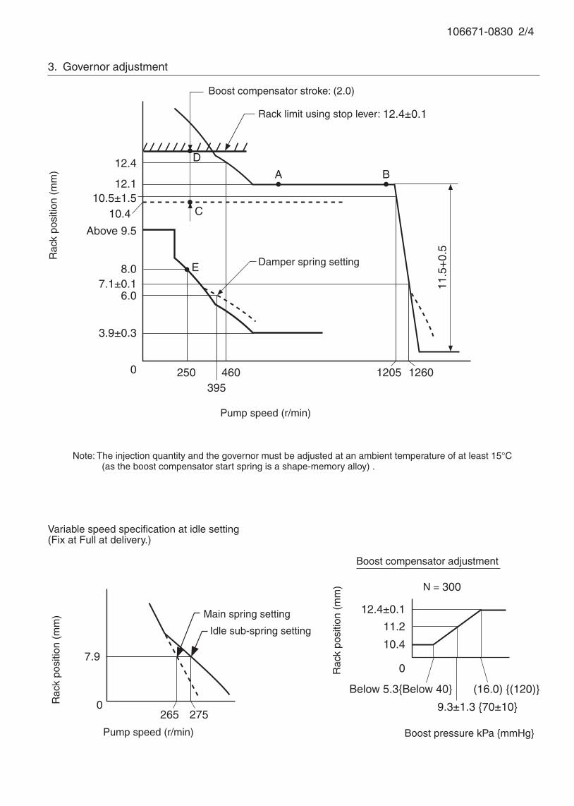
106671-0830 2/4
3. Governor adjustment
Above 9.5
0 250 1260
A
E
Rac
k po
sitio
n (m
m)
Pump speed (r/min)
Rack limit using stop lever: 12.4±0.1
Boost compensator stroke: (2.0)
12.4
12.1
3.9±0.3
10.4
8.0
6.0
395
11.5
+0.
5
C
Damper spring setting
12.4±0.1
0
Below 5.3{Below 40} (16.0) {(120)}
N = 300
11.2
10.4
9.3±1.3 {70±10}
Rac
k po
sitio
n (m
m)
Boost pressure kPa {mmHg}
Boost compensator adjustment
Note: The injection quantity and the governor must be adjusted at an ambient temperature of at least 15°C (as the boost compensator start spring is a shape-memory alloy) .
D
B
10.5±1.5
7.1±0.1
460 1205
7.9
2650
Variable speed specification at idle setting(Fix at Full at delivery.)
Main spring setting
Pump speed (r/min)
Rac
k po
sitio
n (m
m)
Idle sub-spring setting
275
106671-0830 3/4
5. Aneroid compensator kit adjustment
[1] Aneroid compensator adjustment
[2] Adjustment at governor installationWith the load control lever in the Full position (pump speed N = 1100 r/min), screw in the aneroid
compensator assembly so that the following performance can be obtained.
Absolute pressure kPa {mmHg}
Rac
k po
sitio
n (m
m)
Q = (164.6)±3 cm3/1000 st
Q = 139±2 cm3/1000 st
79.4±2.7 {596±20} 57.6±0.7 {432±5}
12.1
(11.1)
Setscrew
Adjust clearance to 0.1 ~ 0.5 mm(using setscrew)
106671-0830 4/4
Stop lever angle
R=12.4±0.1
Stop
(Secure at Full at delivery)
Normal
16.5°±5°
Drive side
Stopper bolt setting
Full-speed
Speed-control lever angle
Idling
24°±5°
N=275
30°±5°
32°±5°
Idling
30.5° ±3°
22°±5°
Full-load
Load-control lever angle
Stopper bolt setting
Timing setting
At No. 1 plunger’s beginning of injection position
Approx. 30°Coupling key groove position

1/3
Ass'y No.: 106671-1447ENGINE MODEL: 6SD1-TC2
No.
Actuator: EP/RED-Ⅲ Timing device: EP/SPGH
1.Test condition
Date:
4.Injection quantity
5.Timing Advance specification
Pump speed(r/min)
Advance
angle(°)
Pump rotation: Counter clockwise (viewed from drive side)
Injection pump: PE6P
105691-3140
kgf/cm2}
2.Injection timing
Pre-stroke:No.1 Plunger 4.2 ± 0.03mm Note: Perform at voltage V
Injection order:
Plungers are numbered from the Governor °± )
(12.0) 1.59 800 151.7±2 ±3 Basic
C O N F I D E N T I A L
INJ.PUMP CALIBRATION DATA
Company:
25 Oct 2001
ISUZU 1-15602-142-7
106060-5771
Injection pipe: Outer Dia.8 mm× Inner Dia.3 mm- Length 600 mm
Nozzle opening pressure: 17.2 MPa{ 175 kgf/cm2} Transfer pump pressure: 157 kPa{ 1.6
Nozzle:105780-0000 Nozzle Holder:105780-2080(Bosch Type No.DN12SD12T) (Bosch Type No.EF8511/9)
Nozzle & Nozzle Holder Ass'y :105780-8140 (Bosch Type No.EF8511/9A)
Overflow valve opening pressure: 127 kPa{ 1.3 kgf/cm2}
Test Oil:ISO4113 or SAE Standard Test Oil{SAE J967d} Oil Temp.:40 ℃+5
side. ( interval:
Adjust-
ing point
Rackposition (mm)
Pumpspeed(r/ min)
Max. varbet. cyl
(%) Remarks
8
Bosch Automotive Systems Corporation
Service Department
3-4-1 Kitano, Niiza-shi, Saitama-ken, 352-8572 Japan
Tel. (048)470-1559, Fax. (048)474-9856
105952-0223
REDⅢ GOV. C/U : 15mm
Injection q' ty
( cm3 / 1000 strokes)Vist
(V)
(6.9) Approx.2.6 225 8.9±3.2 ±13
1 - 5 ,1 - 3 ,1 - 6 ,1 - 2 ,1 - 460°±15′ 120°±15′ 180°±15′ 240°±15′ 300°±15′
106671-1447 2/3
■■■■■RED RED RED RED RED ⅢⅢⅢⅢⅢ governor governor governor governor governor Confirmation of the control rack position sensor's output characteristics
(Rack 15mm , Span 6mm)
When the rack sensor output voltages are V1 and V2, confirm that rack positions R1 and R2
are as specified below.
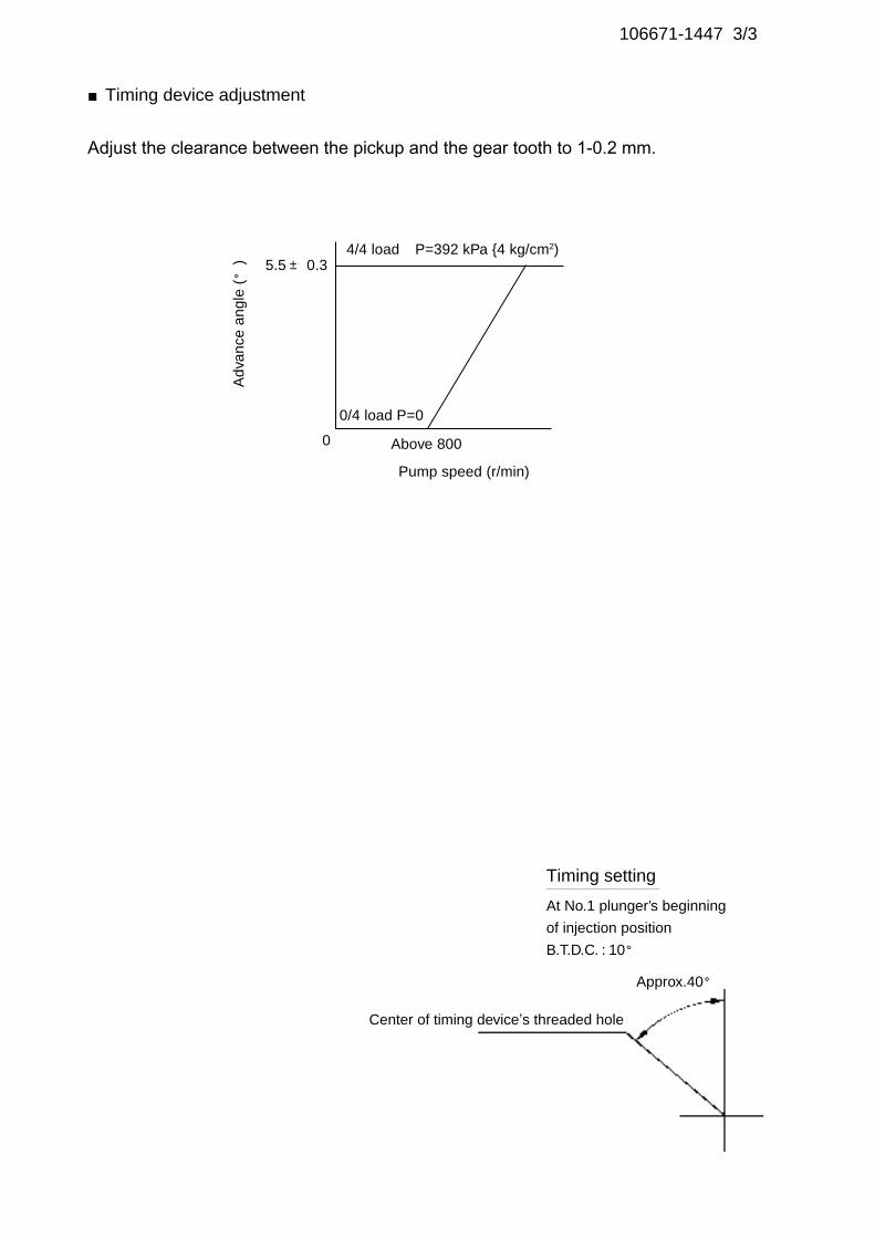
106671-1447 3/3
■Timing device adjustment
Adjust the clearance between the pickup and the gear tooth to 1-0.2 mm.
Pump speed (r/min)
Adv
ance
ang
le (°
)4/4 load
Above 8000
5.5± 0.3
0/4 load P=0
P=392 kPa {4 kg/cm2)
At No.1 plunger’s beginning
of injection position
B.T.D.C. : 10°
Timing setting
Approx.40°
Center of timing device’s threaded hole

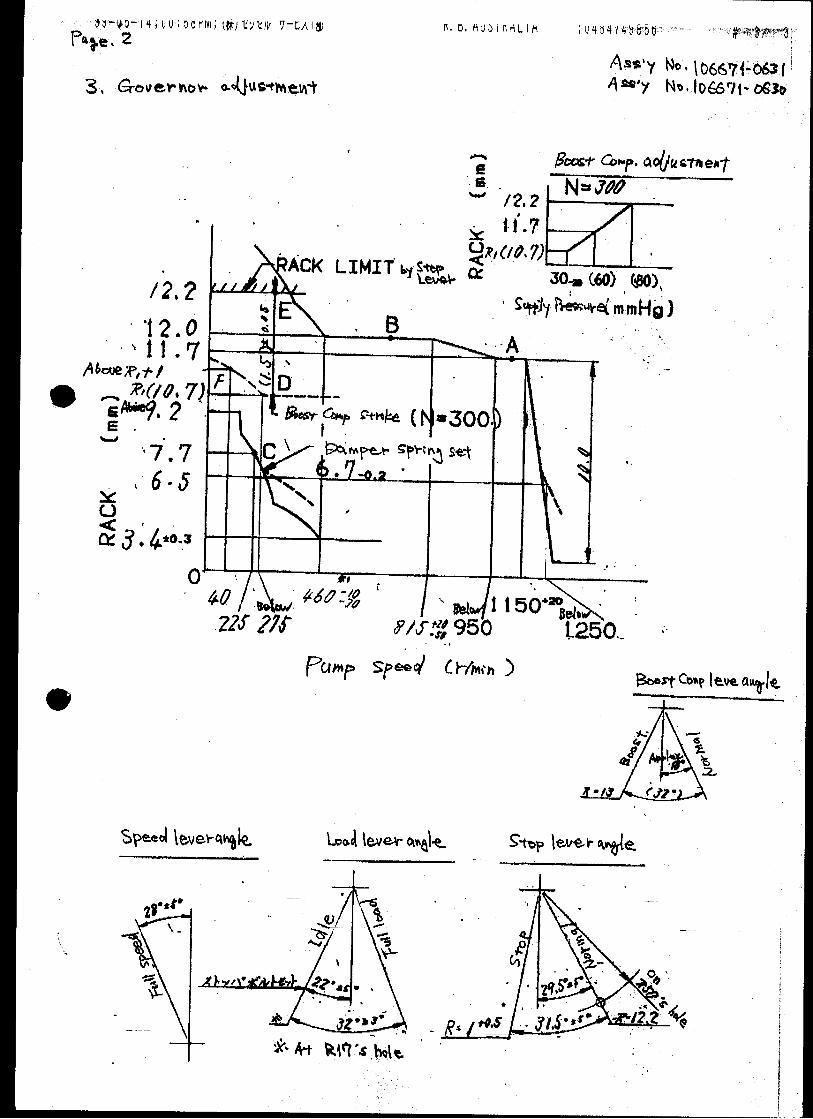
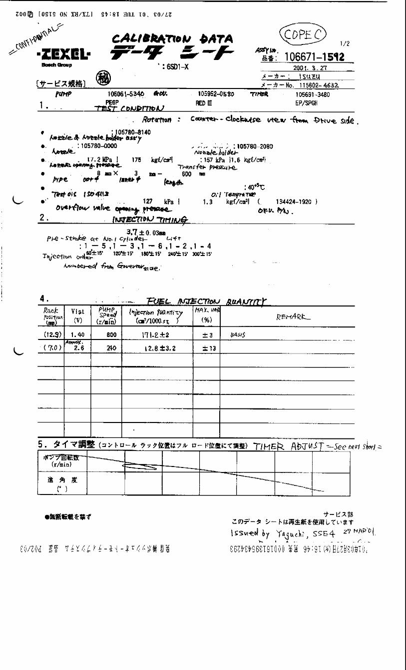
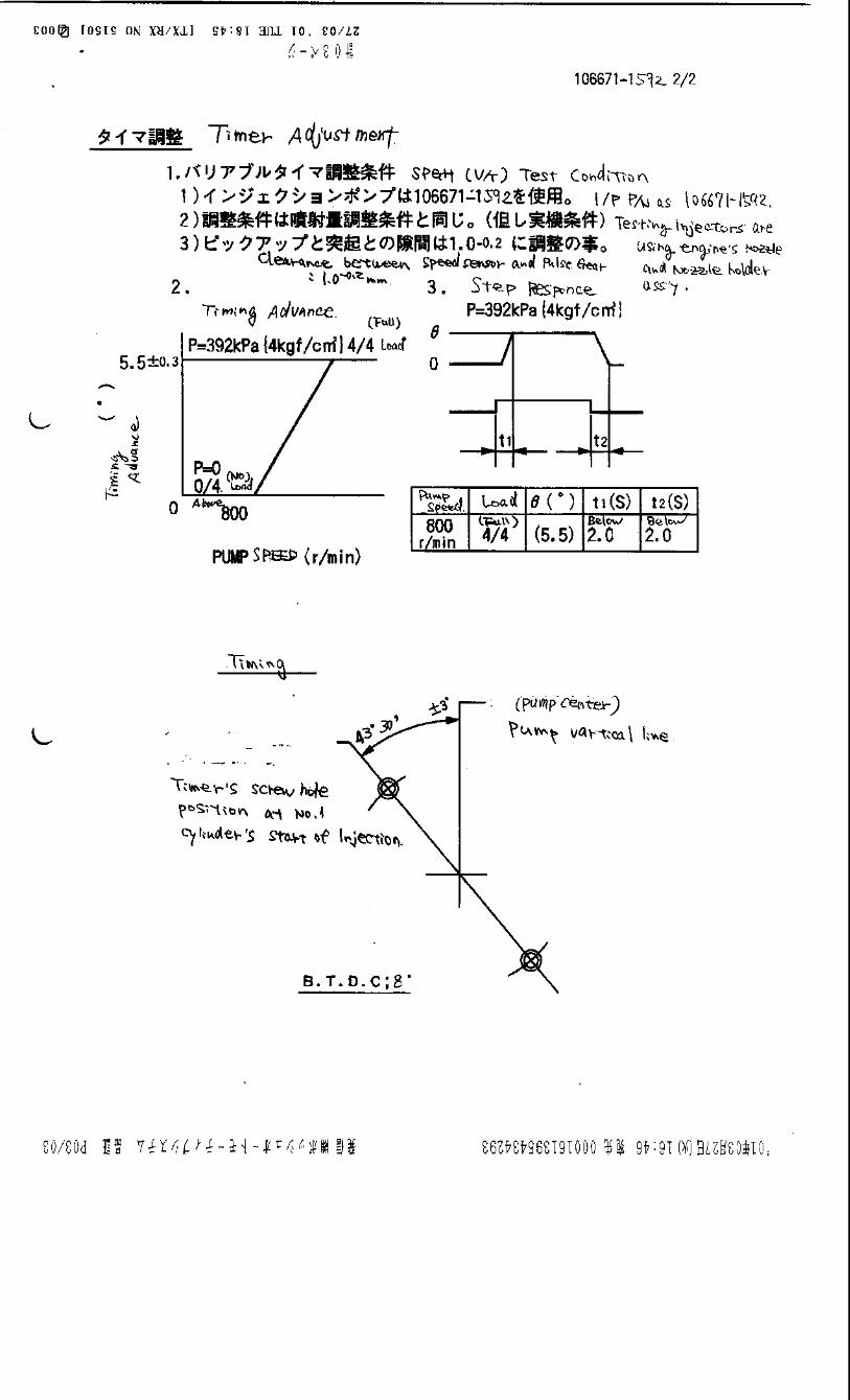
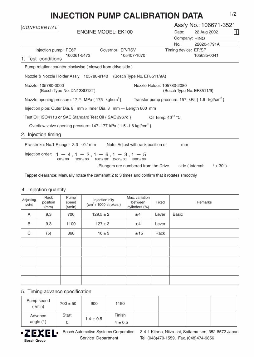
Adjustingpoint
Rackposition
(mm)
Pumpspeed(r/min)
Injection q'ty(cm3 / 1000 strokes )
Max. variationbetween
cylinders (%)Fixed Remarks
A 9.3 700 129.5 ± 2 ± 4 Lever Basic
B 9.3 1100 127 ± 3 ± 4 Lever
C (5) 360 16 ± 3 ± 15 Rack
Injection order:
Pump speed(r/min)
700 ± 50 900 1150
Advanceangle (° )
Start
0 1.4 ± 0.5
Finish
4 ± 0.5
4. Injection quantity
5. Timing advance specification
Bosch Automotive Systems Corporation
Service Department
3-4-1 Kitano, Niiza-shi, Saitama-ken, 352-8572 Japan
Tel. (048)470-1559, Fax. (048)474-9856
Company:
Ass'y No.: 106671-3521ENGINE MODEL: EK100
No. Governor: EP/RSV Timing device: EP/SP
1. Test conditions
Date:
Pump rotation: counter clockwise ( viewed from drive side )
Injection pump: PE6P105407-1670 105635-0041
kgf/cm2 }
2. Injection timing
Pre-stroke: No.1 Plunger 3.3 - 0.1mm mm
Plungers are numbered from the Drive ° ± 30' ).
CONFIDENTIAL
INJECTION PUMP CALIBRATION DATA
22 Aug 2002
22020-1791A
106061-5472
Injection pipe: Outer Dia. 8 mm × Inner Dia. 3 mm Length 600 mm
Nozzle opening pressure: 17.2 MPa { 175 kgf/cm2 }
Nozzle: 105780-0000 Nozzle Holder: 105780-2080(Bosch Type No. DN12SD12T) (Bosch Type No. EF8511/9)
Nozzle & Nozzle Holder Ass'y: 105780-8140 (Bosch Type No. EF8511/9A)
Overflow valve opening pressure: 147~177 kPa { 1.5~1.8 kgf/cm2 }
Test Oil: ISO4113 or SAE Standard Test Oil { SAE J967d } Oil Temp. 40+5 °C
side ( interval:
1
Transfer pump pressure: 157 kPa { 1.6
Note: Adjust with rack position of
HINO
1 4 , 1 2 , 1 6 , 1 3 , 1 560°± 30' 120°± 30' 180°± 30' 240°± 30' 300°± 30'
1/2
Tappet clearance: Manually rotate the camshaft 2 to 3 times and confirm that it rotates smoothly.
(qA-27 qB qA-19)

106671-3521 2/2
3. Governor adjustment
Pump speed (r/min)
0360 1100+10 1210-40
A9.3
8
Rac
k po
sitio
n (m
m)
(5)
Above 14
4
Recommended speed droop adjustment screw position: 5(notches from fully tightened position)
Perform torque control spring adjustment when necessary.
B
C
Speed-control lever angle
Idling
Stopper bolt setting
Full-speed
(28°) ±5°
(9°)±5°
53°±5°
27°±5°
Stop lever angle
Normal Stop
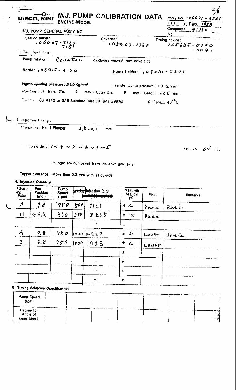
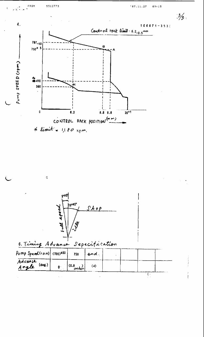
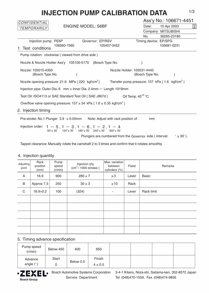
Adjustingpoint
Rackposition
(mm)
Pumpspeed(r/min)
Injection q'ty(cm3 / 1000 strokes )
Max. variationbetween
cylinders (%)Fixed Remarks
A 16.9 900 280 ± 7 ± 3 Lever Basic
B Approx 7.3 250 30 ± 3 ± 10 Rack
C 18.9+0.2 100 (324) - Lever Rack limit
Injection order:
Pump speed(r/min)
Below 450 400 650
Advanceangle (° )
Start
0 Below 0.5
Finish
4 ± 0.5
4. Injection quantity
5. Timing advance specification
Bosch Automotive Systems Corporation
Service Department
3-4-1 Kitano, Niiza-shi, Saitama-ken, 352-8572 Japan
Tel. (048)470-1559, Fax. (048)474-9856
Company:
Ass'y No.: 106671-4451ENGINE MODEL: S6BF
No. Governor: EP/RSV Timing device: EP/SPG
1. Test conditions
Date:
Pump rotation: clockwise ( viewed from drive side )
Injection pump: PE6P105407-3452 105681-0231
kgf/cm2 }
2. Injection timing
Pre-stroke: No.1 Plunger 3.9 ± 0.05mm mm
Plungers are numbered from the ° ± 30' ).
CONFIDENTIAL
INJECTION PUMP CALIBRATION DATA
10 Apr 2003
36265-23180
106060-7560
Injection pipe: Outer Dia. 6 mm × Inner Dia. 2.4mm Length 1019mm
Nozzle opening pressure: 21.6 MPa { 220 kgf/cm2 }
Nozzle: 105015-4350 Nozzle Holder: 105031-4440(Bosch Type No. ) (Bosch Type No. )
Nozzle & Nozzle Holder Ass'y: 105100-5170 (Bosch Type No. )
Test Oil: ISO4113 or SAE Standard Test Oil { SAE J967d } Oil Temp. 40+5 °C
side ( interval:
2
Transfer pump pressure: 157 kPa { 1.6
Note: Adjust with rack position of
1 5 , 1 3 , 1 6 , 1 2 , 1 460°± 30' 120°± 30' 180°± 30' 240°± 30' 300°± 30'
MITSUBISHI
Governor
1/3
Tappet clearance: Manually rotate the camshaft 2 to 3 times and confirm that it rotates smoothly.
TEMPORARILY
(qA-27 qB qA-19)
Overflow valve opening pressure: 157 ± 34 kPa { 1.6 ± 0.35 kgf/cm2 }

106671-4451 2/3
3. Governor adjustment
20+1
16.9
9.2
0
250 1100+10 (1190)±25
A
B
Rac
k po
sitio
n (m
m)
Pump speed (r/min)
400±25
7.3
Rack limit;18.9+0.2
Idle sub-spring setting;
9.2-0.5
C
Recommended speed droop adjustment screw position: 10 (notches from fully tightened position; fix in this position)
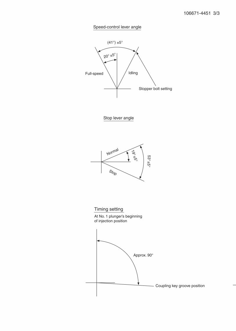
106671-4451 3/3
(41°) ±5°
20° ±5°
Coupling key groove position
Stop adjuster screw setting
Speed-control lever angle
Stopper bolt setting
Full-speed
Stop lever angle
Idling
53°±5°
19°±5°
Stop
Normal
Timing setting
At No. 1 plunger’s beginning of injection position
Approx. 90°
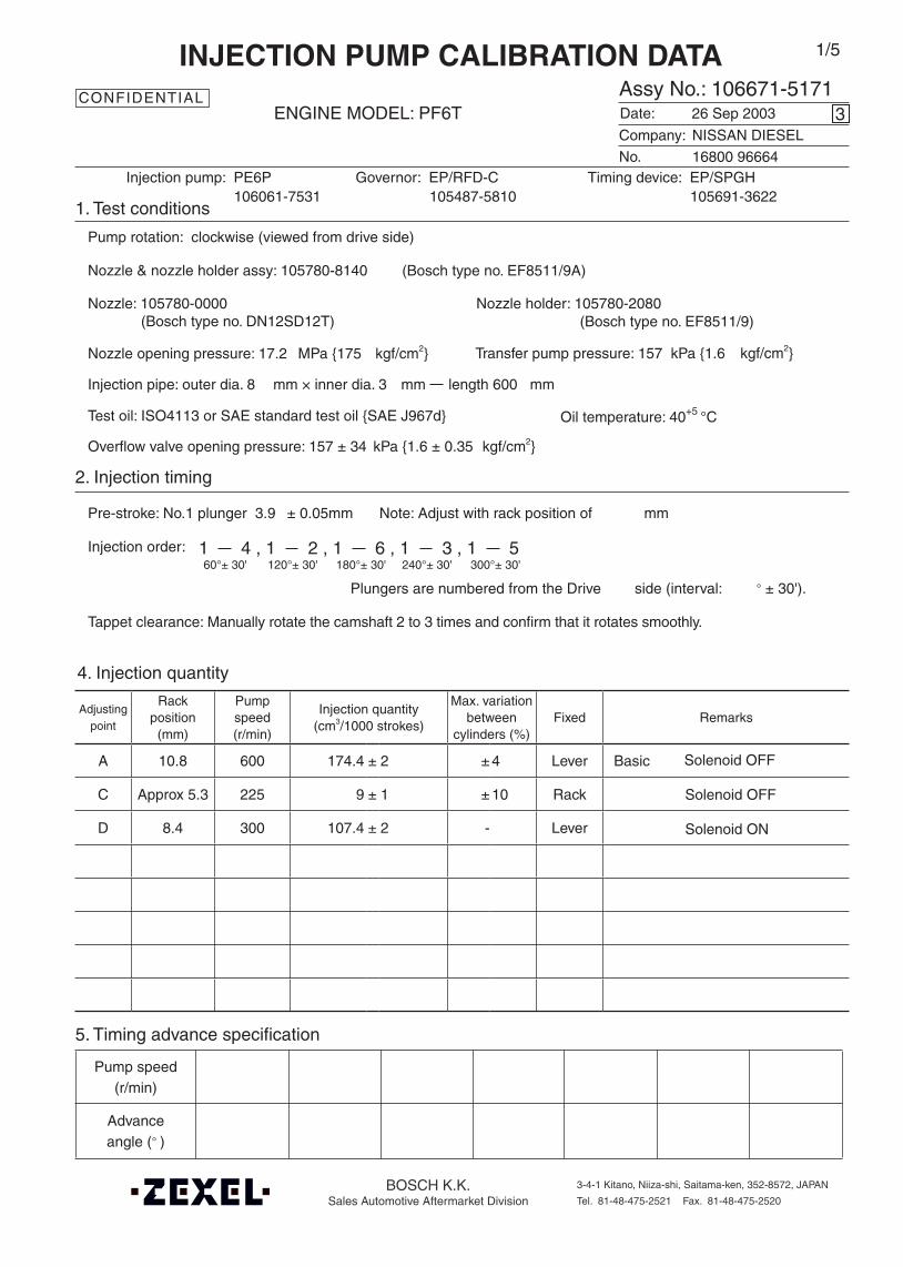
Oil temperature: 40+5 °C
BOSCH K.K.Sales Automotive Aftermarket Division
3-4-1 Kitano, Niiza-shi, Saitama-ken, 352-8572, JAPAN
Tel. 81-48-475-2521 Fax. 81-48-475-2520
Adjustingpoint
Rackposition
(mm)
Pumpspeed(r/min)
Injection quantity(cm3/1000 strokes)
Max. variationbetween
cylinders (%)Fixed Remarks
A 10.8 600 174.4 ± 2 ± 4 Lever Basic
C Approx 5.3 225 9 ± 1 ± 10 Rack
D 8.4 300 107.4 ± 2 - Lever
Injection order:
Pump speed(r/min)
Advanceangle (° )
4. Injection quantity
5. Timing advance specification
Company:
Assy No.: 106671-5171ENGINE MODEL: PF6T
No. Governor: EP/RFD-C Timing device: EP/SPGH
1. Test conditions
Date:
Pump rotation: clockwise (viewed from drive side)
Injection pump: PE6P105487-5810 105691-3622
kgf/cm2}
2. Injection timing
Pre-stroke: No.1 plunger 3.9 ± 0.05mm mm
Plungers are numbered from the Drive ° ± 30').
CONFIDENTIAL
INJECTION PUMP CALIBRATION DATA
26 Sep 2003
NISSAN DIESEL
16800 96664
106061-7531
Injection pipe: outer dia. 8 mm × inner dia. 3 mm length 600 mm
Nozzle opening pressure: 17.2 MPa {175 kgf/cm2}
Nozzle: 105780-0000 Nozzle holder: 105780-2080(Bosch type no. DN12SD12T) (Bosch type no. EF8511/9)
Nozzle & nozzle holder assy: 105780-8140 (Bosch type no. EF8511/9A)
Test oil: ISO4113 or SAE standard test oil {SAE J967d}
side (interval:
3
Transfer pump pressure: 157 kPa {1.6
Note: Adjust with rack position of
1 4 , 1 2 , 1 6 , 1 3 , 1 560°± 30' 120°± 30' 180°± 30' 240°± 30' 300°± 30'
1/5
Tappet clearance: Manually rotate the camshaft 2 to 3 times and confirm that it rotates smoothly.
Overflow valve opening pressure: 157 ± 34 kPa {1.6 ± 0.35 kgf/cm2}
Solenoid ON
Solenoid OFF
Solenoid OFF

106671-5171 2/5
3. Governor adjustment
Below 160
11.7±0.311.311.1
10.8
8.4
0
10.0
+0.
5
A
D
Rac
k po
sitio
n (m
m)
Pump speed (r/min)
Rack limit using stop lever: 11.1±0.1
10.2
5.3
3.6
C
225
Damper spring setting
Above 6.8
1.5±0.5
410350 460 1150 1240
R1(5.2)
2900
Variable speed specification at idle setting(Fix at Full at delivery.)
Main spring setting
Pump speed (r/min)
Rac
k po
sitio
n (m
m)
4.3±2.0
420
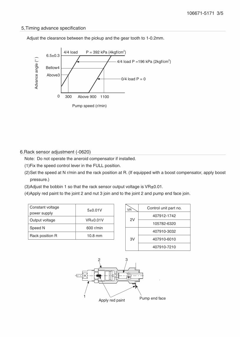
106671-5171 3/5
6.Rack sensor adjustment (-0620)Note: Do not operate the aneroid compensator if installed.
(1)Fix the speed control lever in the FULL position.
(2) Set the speed at N r/min and the rack position at R. (If equipped with a boost compensator, apply boost
pressure.)
(3)Adjust the bobbin 1 so that the rack sensor output voltage is VR±0.01.
(4)Apply red paint to the joint 2 and nut 3 join and to the joint 2 and pump end face join.
1
2 3
Constant voltage
power supply5±0.01V
Output voltage VR±0.01V
Speed N 600 r/min
Rack position R 10.8 mm
VR Control unit part no.
2V407912-1742
105782-6320
3V
407910-3032
407910-6010
407910-7210
Apply red paint Pump end face
300
5.Timing advance specification
Pump speed (r/min)
6.5±0.3
0 Above 900
0/4 load P = 0
4/4 load P = 392 kPa {4kgf/cm2}
Adv
ance
ang
le (
° )
Adjust the clearance between the pickup and the gear tooth to 1-0.2mm.
1100
4/4 load P =196 kPa {2kgf/cm2}
Above3
Bellow4
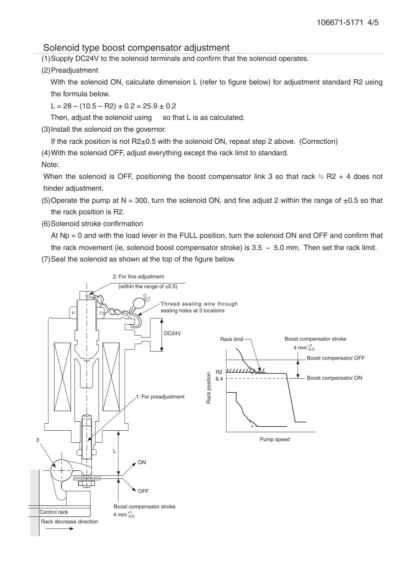
106671-5171 4/5
7.Solenoid type boost compensator adjustment(1) Supply DC24V to the solenoid terminals and confirm that the solenoid operates.
(2) Preadjustment
With the solenoid ON, calculate dimension L (refer to figure below) for adjustment standard R2 using
the formula below.
L = 28 – (10.5 – R2) ± 0.2 = 25.9 ± 0.2
Then, adjust the solenoid using 1 so that L is as calculated.
(3) Install the solenoid on the governor.
If the rack position is not R2±0.5 with the solenoid ON, repeat step 2 above. (Correction)
(4) With the solenoid OFF, adjust everything except the rack limit to standard.
Note:
When the solenoid is OFF, positioning the boost compensator link 3 so that rack R2 + 4 does not
hinder adjustment.
(5) Operate the pump at N = 300, turn the solenoid ON, and fine adjust 2 within the range of ±0.5 so that
the rack position is R2.
(6) Solenoid stroke confirmation
At Np = 0 and with the load lever in the FULL position, turn the solenoid ON and OFF and confirm that
the rack movement (ie, solenoid boost compensator stroke) is 3.5 ~ 5.0 mm. Then set the rack limit.
(7) Seal the solenoid as shown at the top of the figure below.
2: For fine adjustment
(within the range of ±0.5)
DC24V
1: For preadjustment
ON
OFF
Control rack
Rack decrease direction
Boost compensator OFF
Rack limit
L
3
8.4
Thread sealing wire through sealing holes at 3 locations
Rac
k po
sitio
n
Pump speed
Boost compensator stroke
4 mm +1-0.5
Boost compensator ON
Boost compensator stroke
4 mm +1-0.5
R2
106671-5171 5/5
Speed-control lever angle
Idling
Stopper bolt setting
Stop lever angle
Full-speed
(Secure at full at delivery)
Coupling key groove position
N=290(13°) ±5°
5.5°±5°
45° ±5°34.5°±3°
Normal
33°±5° 33°±5°
R=11.1±0.1Stop
Load lever angle
Full-load
Idling
Stopper bolt setting
Timing setting
At No. 1 plunger’s beginning of injection position
Approx. 30°
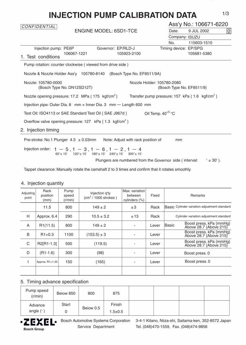
Adjustingpoint
Rackposition
(mm)
Pumpspeed(r/min)
Injection q'ty(cm3 / 1000 strokes )
Max. variationbetween
cylinders (%)Fixed Remarks
11.5 800 149 ± 2 ± 3 Rack
H Approx. 6.4 290 10.5 ± 3.2 ± 13 Rack
A R1(11.5) 800 149 ± 2 - Lever
B R1+0.3 1100 (153.5) ± 3 - Lever
C R2[R1-1.3] 500 (119.5) - Lever
D (R1-1.6) 300 (98) - Lever
I Approx. R1+1.35 150 (165) - Lever
Injection order:
Pump speed(r/min)
Beiow 850 800 875
Advanceangle (° )
Start
0Beiow 0.5
Finish
1.5±0.5
4. Injection quantity
5. Timing advance specification
Bosch Automotive Systems Corporation
Service Department
3-4-1 Kitano, Niiza-shi, Saitama-ken, 352-8572 Japan
Tel. (048)470-1559, Fax. (048)474-9856
Company:
Ass'y No.: 106671-6220ENGINE MODEL: 6SD1-TCE
No. Governor: EP/RLD-J Timing device: EP/SPG
1. Test conditions
Date:
Pump rotation: counter clockwise ( viewed from drive side )
Injection pump: PE6P105923-2100 105681-5380
kgf/cm2 }
2. Injection timing
Pre-stroke: No.1 Plunger 4.5 ± 0.03mm mm
Plungers are numbered from the ° ± 30' ).
CONFIDENTIAL
INJECTION PUMP CALIBRATION DATA
9 JUL 2002
NISSAN DIESEL
115603-1510
106067-1221
Injection pipe: Outer Dia. 8 mm × Inner Dia. 3 mm Length 600 mm
Nozzle opening pressure: 17.2 MPa { 175 kgf/cm2 }
Nozzle: 105780-0000 Nozzle Holder: 105780-2080(Bosch Type No. DN12SD12T) (Bosch Type No. EF8511/9)
Nozzle & Nozzle Holder Ass'y: 105780-8140 (Bosch Type No. EF8511/9A)
Overflow valve opening pressure: 127 kPa { 1.3 kgf/cm2 }
Test Oil: ISO4113 or SAE Standard Test Oil { SAE J967d } Oil Temp. 40+5 °C
side ( interval:
0
Transfer pump pressure: 157 kPa { 1.6
Note: Adjust with rack position of
1 5 , 1 3 , 1 6 , 1 2 , 1 460°± 15' 120°± 15' 180°± 15' 240°± 15' 300°± 15'
ISUZU
Governor
1/3
Tappet clearance: Manually rotate the camshaft 2 to 3 times and confirm that it rotates smoothly.
Boost press. 0
Cylinder variation adjustment standard
Cylinder variation adjustment standardBasic
Basic Boost press. kPa {mmHg}Above 28.7 {Above 215}Boost press. kPa {mmHg}Above 28.7 {Above 215}
Boost press. kPa {mmHg}Above 28.7 {Above 215}
Boost press. 0

106671-6220 2/3
3. Governor adjustment
R1+0.3R1(11.5)R1-0.35R1-0.45
0Below 200
(280)
(470) (560) 700
(900)
1310
(1050)
(750)
Rac
k po
sitio
n (m
m)
Pump speed (r/min)
Approx. R1+1.35
(1180)
1200
A
C
I
B
Torque cam no. ‘AD53’
Boost compensator stroke:1.15±0.1 mm
R2[R1-1.3]10.8±0.1
6.8±1.0D
8.5
6.5
0185
240 290315 430 820
Rac
k po
sitio
n (m
m)
Pump speed (r/min)
Approx 6.4
0.5+0.5-0.45
8.0±0.5
4.0±0.1
R2[R1-1.3]
R2-1.15
0
10.0±1.3 {75±10}
Approx 15.3 {Approx 115}
N = 500
Rac
k po
sitio
n (m
m)
Boost pressure kPa {mmHg}
Boost compensator adjustment
Full load adjustment
Idling adjustment

106671-6220 3/3
22°±5°
Speed-control lever angle
Idlin
g
Stopper bolt setting
Stop lever angle
Stop
Full-speed
Normal
29.5°±3°
Center of timing device's threaded hole
27°±5°
41°±5°
Timing setting
At No. 1 plunger’s beginning of injection positionB.T.D.C.: 10°
Approx. 50°
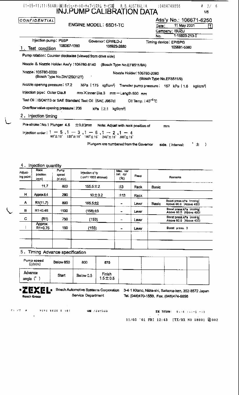
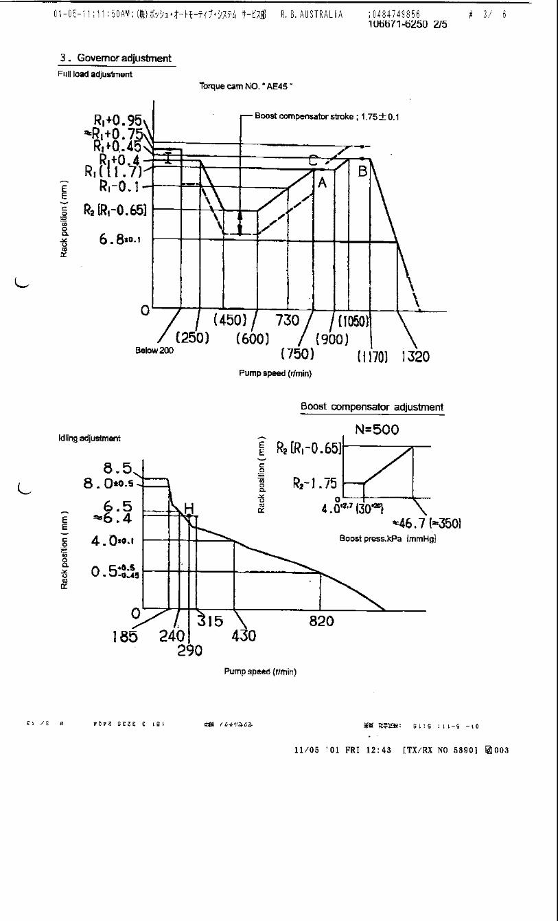
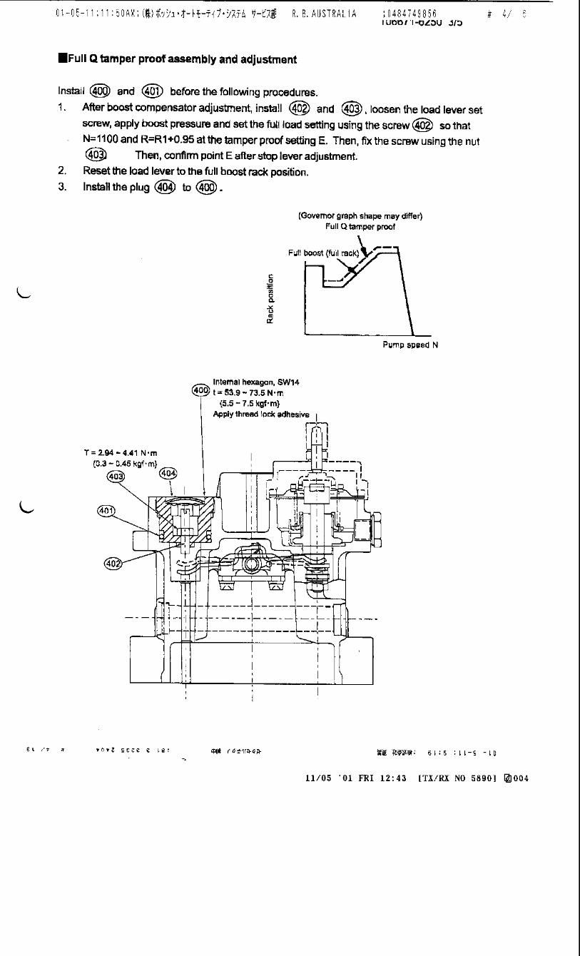
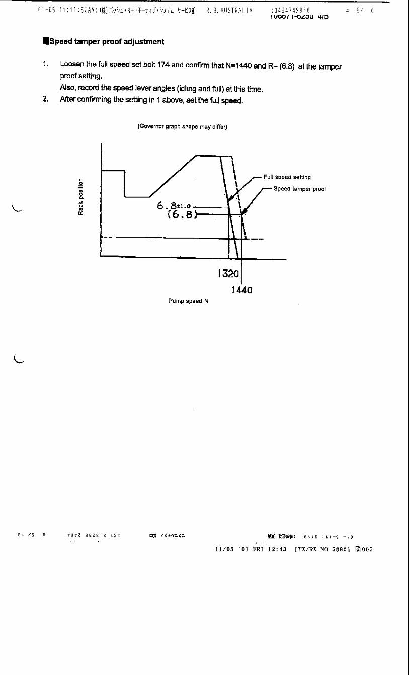
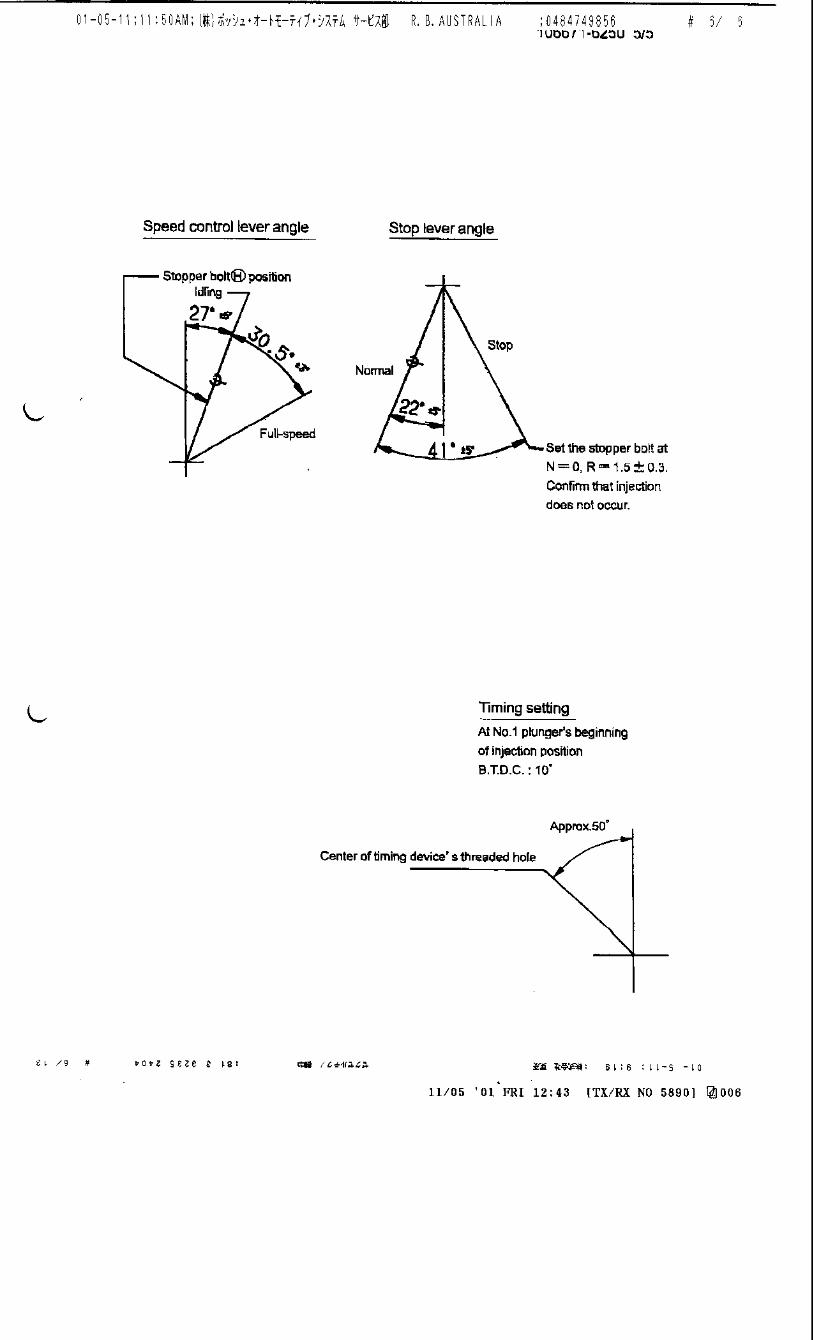
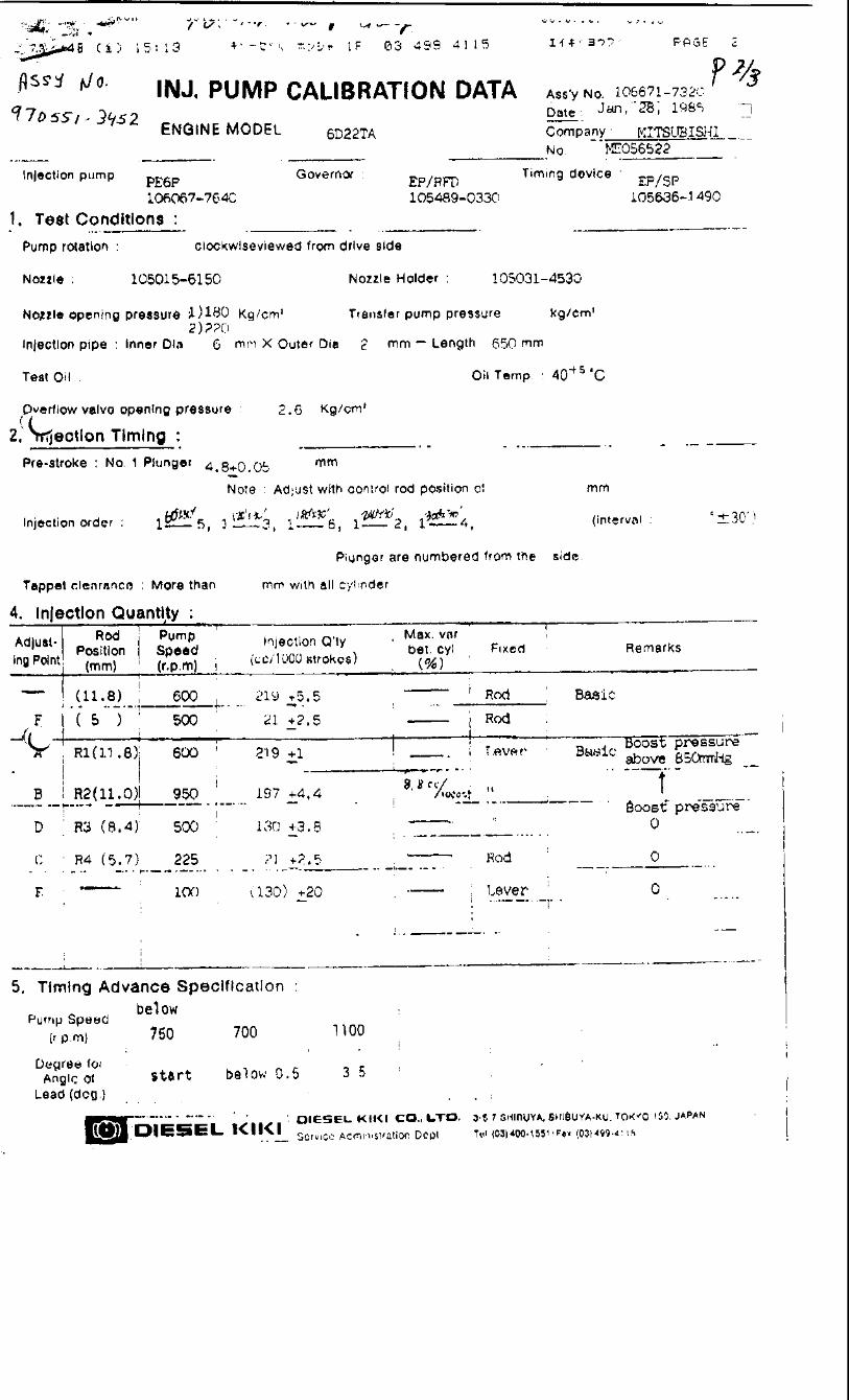


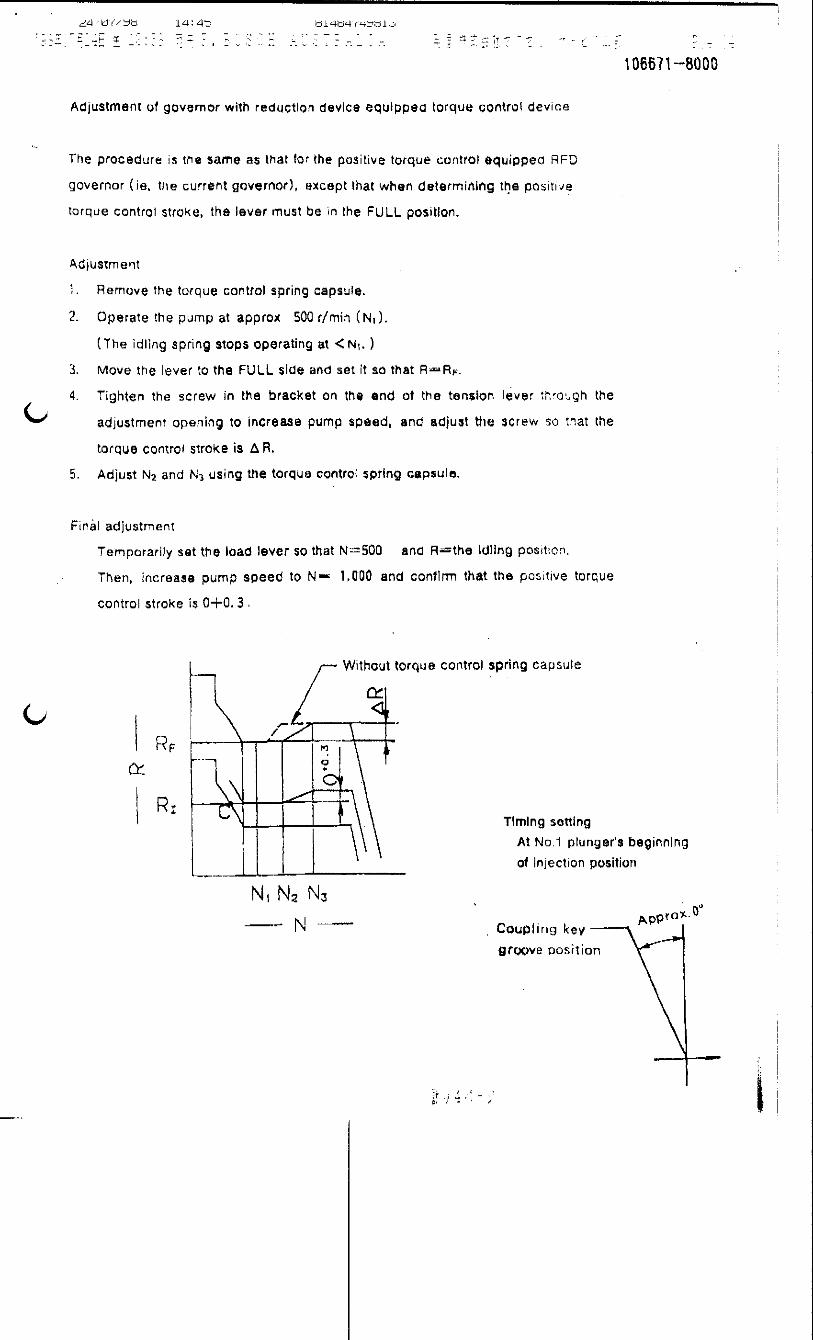
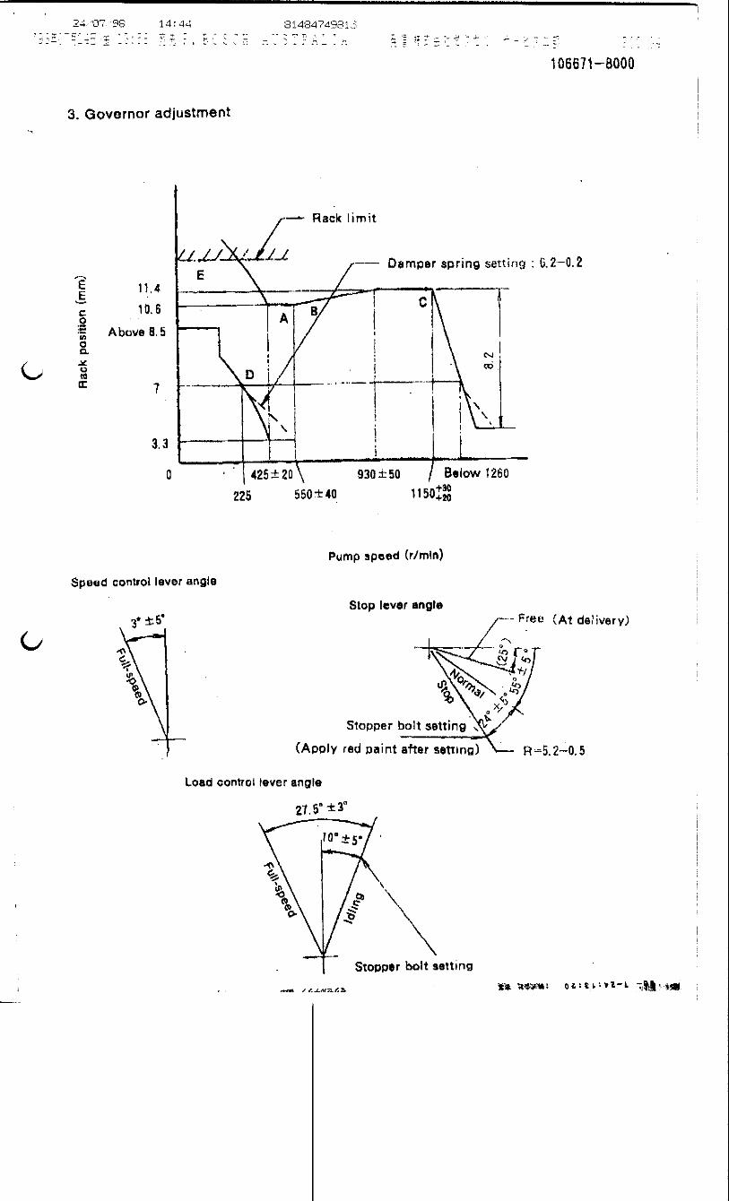
106671-3841 ZEXEL test values diesel fuel-injection equipment 02/09/03 09:20:09 Page 1
ZEXEL Ass'y No. 106671-3841
Bosch Ass'y No.
Bosch Typecode
Engine Type EK200
Manufacturer HINO
Edition date 28/09/00 (2)
1 Adjustment conditions
CAT Designation Unit Set value min. max. Actual values OT
Test oil ISO4113 or {SAEJ967d}
...
P Test Oil Temperature degC 40 40 45
Nozzle and nozzle holder 105780-8140
Bosch type code EF8511/9A
Nozzle 105780-0000
Bosch type code DN12SD12T
Nozzle holder 105780-2080
Bosch type code EF8511/9
P Opening Pressure MPa 17.2
P Opening Pressure kgf/cm2 175
Iinjection Pipe mm 8-3-600
Outer diameter - inner diameter - length (mm)
Overflow valve 134424-0920
P Overflow valve opening pressure kPa 162 147 177
P Overflow valve opening pressure kgf/cm2 1.65 1.5 1.8
P Tester oil delivery pressure kPa 157 157 157
P Tester oil delivery pressure kgf/cm2 1.6 1.6 1.6
Direction of rotation (viewed from drive side) L
Left
2 Adjustment specification
2.1 Injection timing adjustment
CAT Designation Unit Set value min. max. Actual values OT
P Direction of rotation (viewed from drive side) L
Left
P Injection order 1-4-2-6-3-5
S Pre-stroke mm 4.8 4.74 4.8
P Beginning of injection position No.1
Drive side
S Difference between angles 1 deg. 60 59.75 60.25
Cyl 1-4
S Difference between angles 2 deg. 120 119.75 120.25
Cyl.1-2
S Difference between angles 3 deg. 180 179.75 180.25
Cyl 1-6
S Difference between angles 4 deg. 240 239.75 240.25
Cyl 1-3
S Difference between angles 5 deg. 300 299.75 300.25
Cyl 1-5
2.2 Injection quantity adjustment
CAT Designation Unit Set value min. max. Actual values OT
S = Setting value, C = Check value)OT = Outside Tolerance (X is set)
106671-3841 ZEXEL test values diesel fuel-injection equipment 02/09/03 09:20:09 Page 2
P Adjusting point A
P Rack position 7.9
P Pump speed r/min 500 500 500
S Average injection quantity mm3/st. 153 150 156
S Max variation between cylinders % 0 -4 4
P Fixing the lever *
CAT Designation Unit Set value min. max. Actual values OT
P Adjusting point B
P Rack position 7.9
P Pump speed r/min 700 700 700
S Average injection quantity mm3/st. 151 149 153
S Max variation between cylinders % 0 -2 2
P Basic *
P Fixing the lever *
CAT Designation Unit Set value min. max. Actual values OT
P Adjusting point C
P Rack position 8.3
P Pump speed r/min 1075 1075 1075
S Average injection quantity mm3/st. 159 156 162
S Max variation between cylinders % 0 -4 4
P Fixing the lever *
CAT Designation Unit Set value min. max. Actual values OT
P Adjusting point D
P Rack position 4.0+-0.5
P Pump speed r/min 225 225 225
S Average injection quantity mm3/st. 13 10 16
S Max variation between cylinders % 0 -15 15
P Fixing the rack *
CAT Designation Unit Set value min. max. Actual values OT
P Adjusting point E
P Rack position 8.6+-0.5
P Pump speed r/min 100 100 100
S Average injection quantity mm3/st. 140 140 150
P Fixing the lever *
P Rack limit *
CAT Designation Unit Set value min. max. Actual values OT
P Adjusting point F
P Rack position 7.2
P Pump speed r/min 1150 1150 1150
S Average injection quantity mm3/st. 134.7 129.7 139.7
P Fixing the lever *
2.3 Governor adjustment
Name
S = Setting value, C = Check value)OT = Outside Tolerance (X is set)
106671-3841 ZEXEL test values diesel fuel-injection equipment 02/09/03 09:20:09 Page 3
RT=0.8TH=2.4mmR1=8.6mmDL=3.3-0.2mmN1=300+25r/minR2=4mm
N:Pump speedR:Rack position (mm)(1)Lever ratio: RT(2)Target shim dimension: TH(3)RACK LIMIT: R1(4)Damper spring setting: DL(5)Adjust the bolt so that the switch goes on at pump speed N = N1 and rack position R = R2.
2.4 Timer adjustment
CAT Designation Unit Set value min. max. Actual values OT
S Pump speed r/min 865+50
P Advance angle deg. 0 0 0
P Load 4/4
Remarks
Start
CAT Designation Unit Set value min. max. Actual values OT
P Pump speed r/min 850
S Advance angle deg. 0.3 0.3
P Load 3/4
CAT Designation Unit Set value min. max. Actual values OT
P Pump speed r/min 1075
S Advance angle deg. 4.5 4.2 4.8
P Load 4/4
Remarks
Finish
2.5 Speed control lever angle
Name
a=17deg+-5deg
F:Full speed
S = Setting value, C = Check value)OT = Outside Tolerance (X is set)
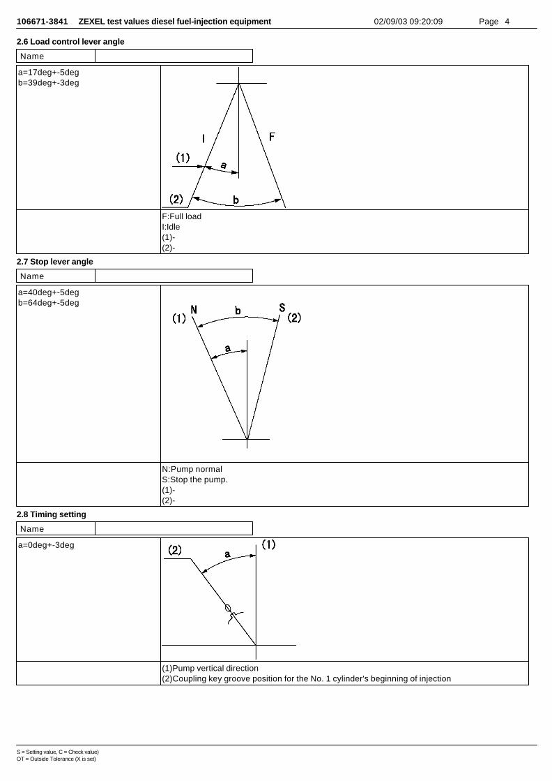
106671-3841 ZEXEL test values diesel fuel-injection equipment 02/09/03 09:20:09 Page 4
2.6 Load control lever angle
Name
a=17deg+-5degb=39deg+-3deg
F:Full loadI:Idle(1)-(2)-
2.7 Stop lever angle
Name
a=40deg+-5degb=64deg+-5deg
N:Pump normalS:Stop the pump.(1)-(2)-
2.8 Timing setting
Name
a=0deg+-3deg
(1)Pump vertical direction(2)Coupling key groove position for the No. 1 cylinder's beginning of injection
S = Setting value, C = Check value)OT = Outside Tolerance (X is set)

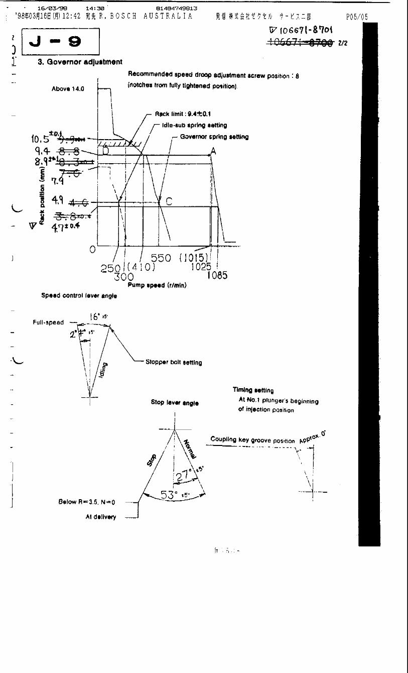
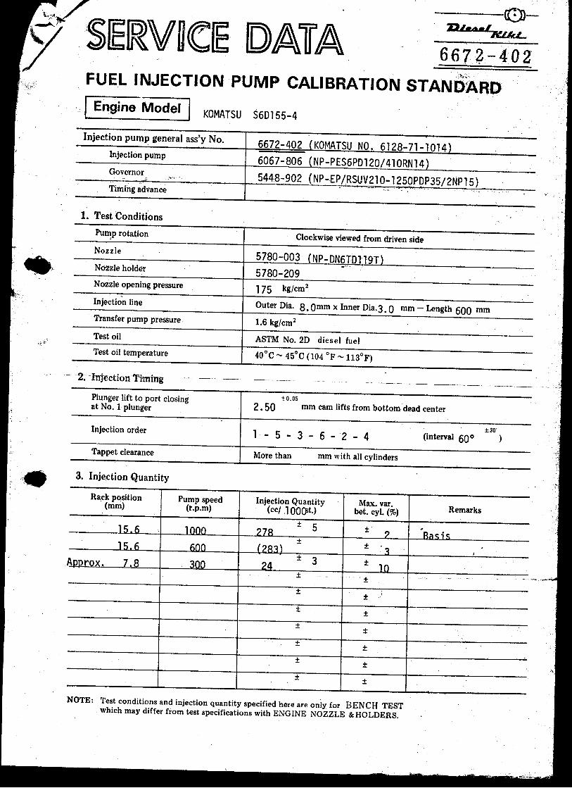

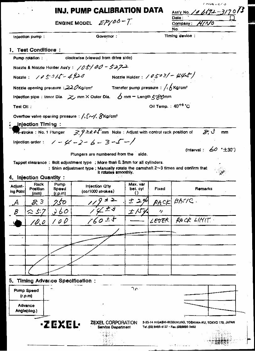
Oil temperature: 40+5 °C
BOSCH K.K.Sales Automotive Aftermarket Division
3-4-1 Kitano, Niiza-shi, Saitama-ken, 352-8572, JAPAN
Tel. 81-48-475-2521 Fax. 81-48-475-2520
Adjustingpoint
Rackposition
(mm)
Pumpspeed(r/min)
Injection quantity(cm3/1000 strokes)
Max. variationbetween
cylinders (%)Fixed Remarks
A 9.8 750 89.3 ± 1 ± 2 Rack Basic
B Approx 8.2 360 14 ± 3 ± 15 Rack
D - 100 187 ± 10 - Lever Rack limit
Injection order:
Pump speed(r/min)
Advanceangle (° )
4. Injection quantity
5. Timing advance specification
Company:
Assy No.: 106672-3740ENGINE MODEL: M10C-TB
No. Governor: EP/RSV Timing device:
1. Test conditions
Date:
Pump rotation: clockwise (viewed from drive side)
Injection pump: PE6P105407-6550
kgf/cm2}
2. Injection timing
Pre-stroke: No.1 plunger 3.9 ± 0.05mm mm
Plungers are numbered from the Drive ° ± 30').
CONFIDENTIAL
INJECTION PUMP CALIBRATION DATA
22 Sep 2004
22020-4990A
106067-1070
Injection pipe: outer dia. 8 mm × inner dia. 3 mm length 600 mm
Nozzle opening pressure: 17.2 MPa {175 kgf/cm2}
Nozzle: 105780-0000 Nozzle holder: 105780-2080(Bosch type no. DN12SD12T) (Bosch type no. EF8511/9)
Nozzle & nozzle holder assy: 105780-8140 (Bosch type no. EF8511/9A)
Test oil: ISO4113 or SAE standard test oil {SAE J967d}
side (interval:
1
Transfer pump pressure: 157 kPa {1.6
Note: Adjust with rack position of
HINO
1 4 , 1 2 , 1 6 , 1 3 , 1 560°± 30' 120°± 30' 180°± 30' 240°± 30' 300°± 30'
1/3
Tappet clearance: Manually rotate the camshaft 2 to 3 times and confirm that it rotates smoothly.
Boost pressure kPa {mmHg}Above 74.6 {Above 560}
Overflow valve opening pressure: 147~177 kPa {1.5~1.8 kgf/cm2}
Boost press. 0
Boost press. 0
106672-3740 2/3
Rack limit
3. Governor adjustment
10.9
0 300
A
Rac
k po
sitio
n (m
m)
Pump speed (r/min)
Boost compensator stroke: 1.4±0.1
Recommended speed droop adjustment screw position: 18 (notches from fully tightened position; fix in this position)
Above 14.0
11.5±0.1
9.8±0.1
6.2±1.5
10.9
9.5
0
3.3+2.0 {25+15}
N = 600
Rac
k po
sitio
n (m
m)
Boost pressure kPa {mmHg}
Boost compensator adjustment
D
798900
Approx 61.3 {Approx 460}
8.2B Idle sub spring setting
Main spring setting
4.8±0.1
750 850
9.0±0.28.4±0.1
360(430)
106672-3740 3/3
70°±5°
Stopper bolt setting
25°±5°
Stop lever angle
Stop Normal
N=0, R=1.0-0.5(Seal at delivery)
Timing setting
At No. 1 plunger’s beginning of injection position
Coupling key groove position
Approx. 50°
Speed-control lever angle
Idling
(8°) ±5°
Full-speedN=900 set
(18°) ±5°
(5°) ±5°
N=750 set
Stopper bolt setting
Pump Assembly # 106672-3810
Governor Assembly # 105407-7100
This Pump and Governor combination is only released to OEM and Test Data is available thru OE as well..

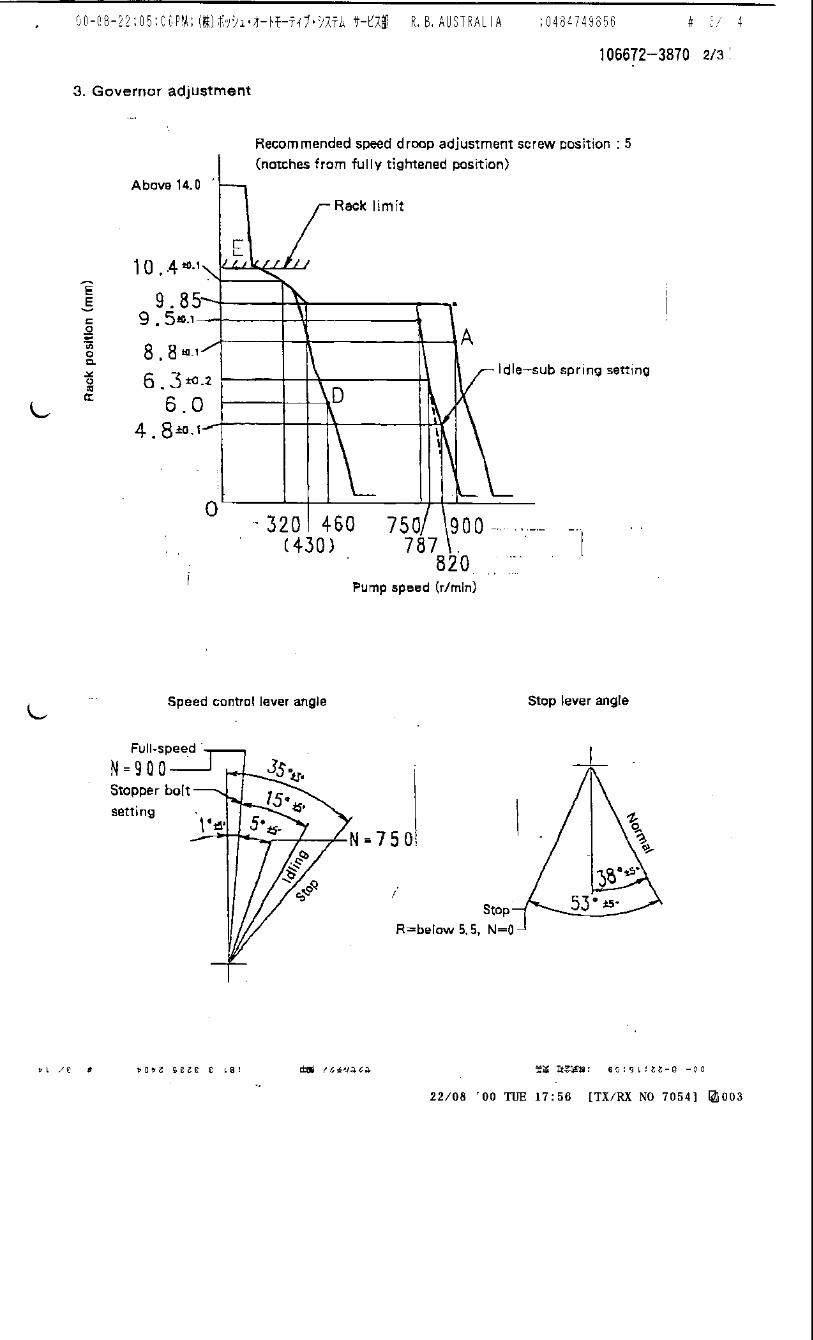

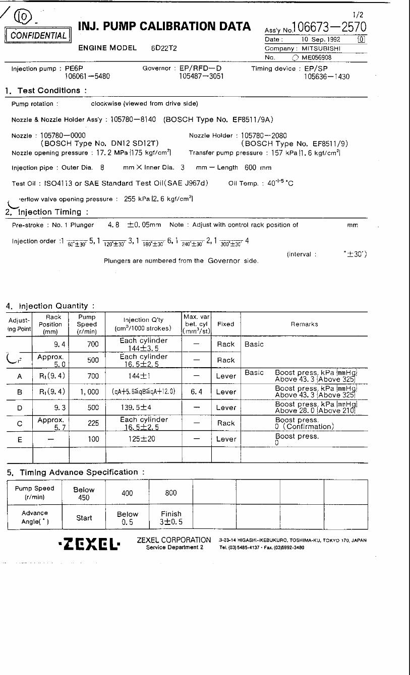
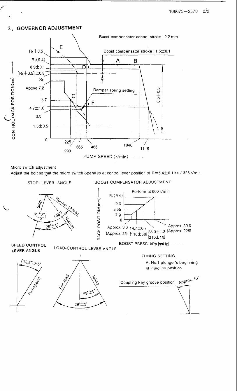

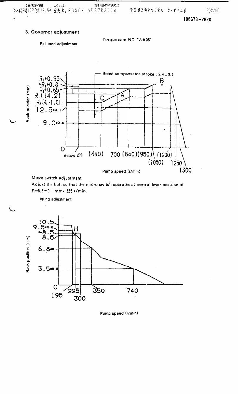
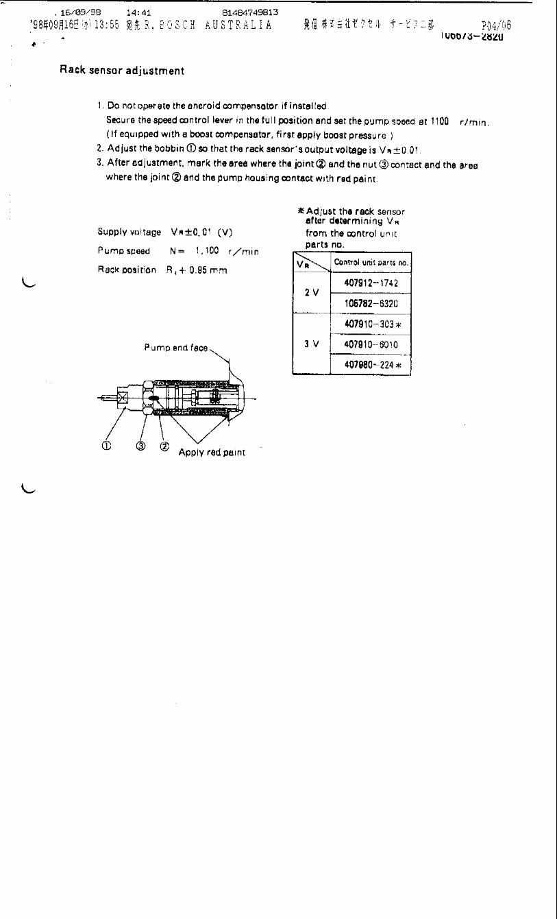

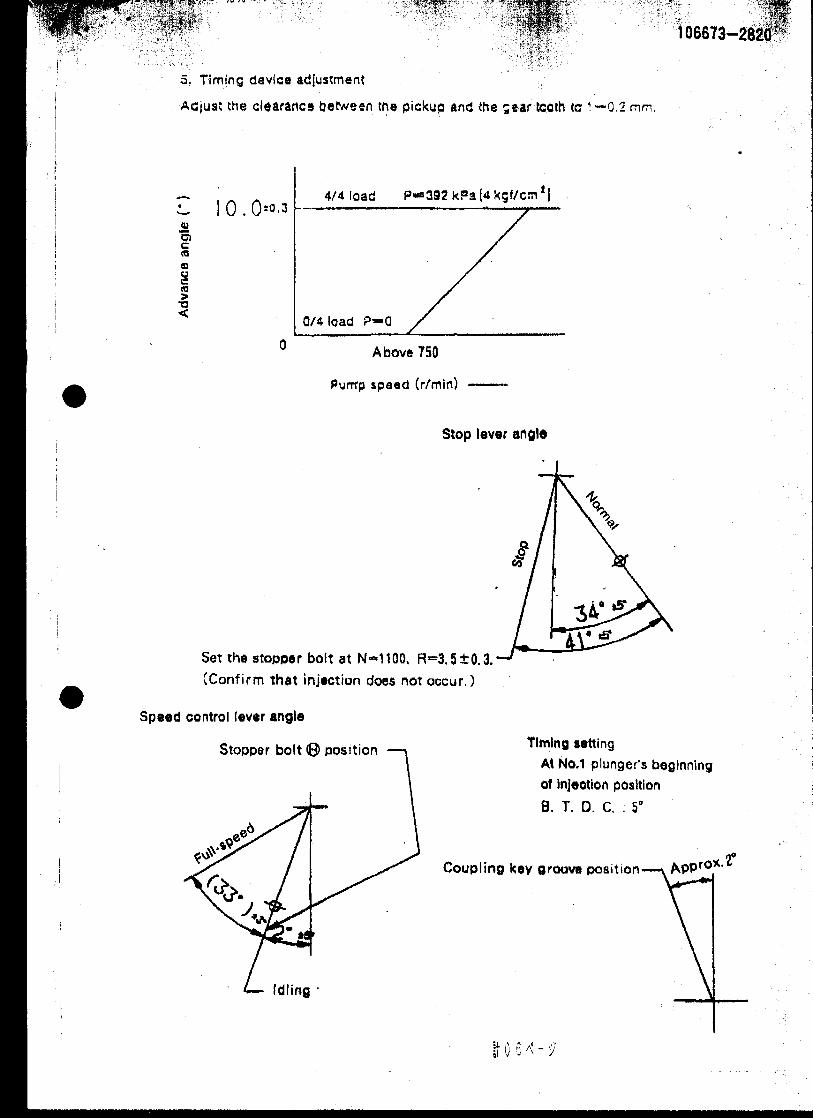


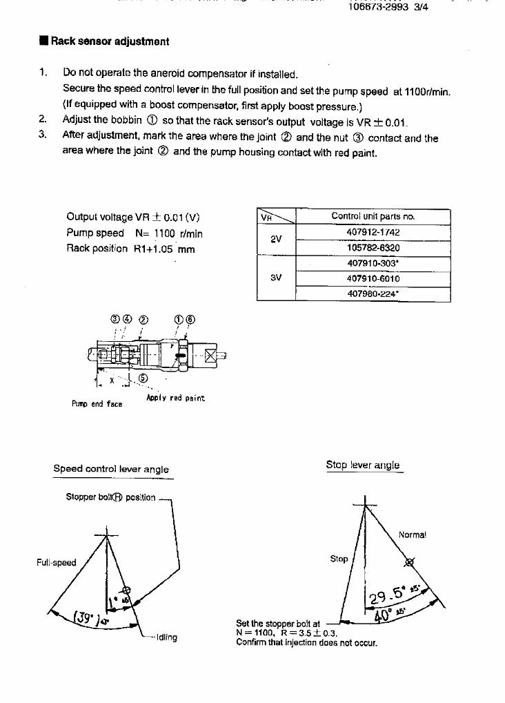

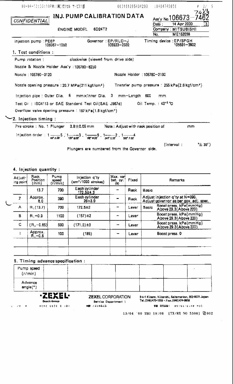
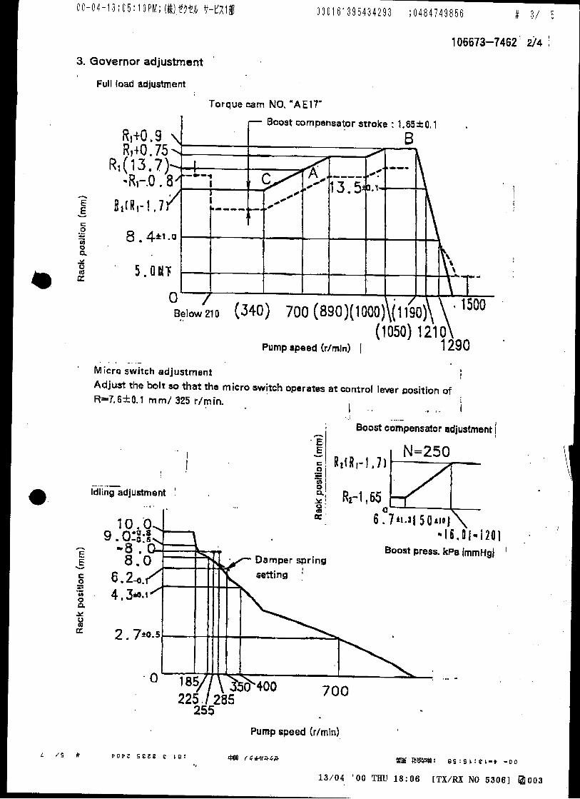
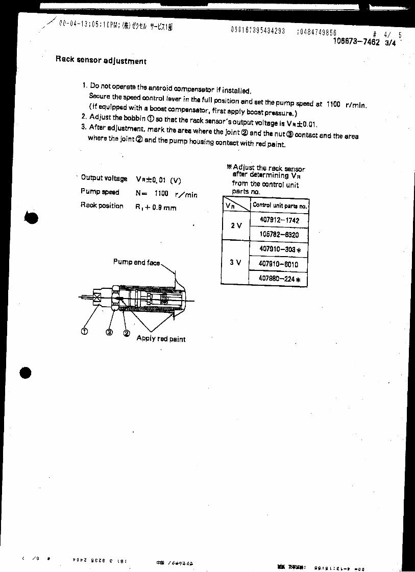
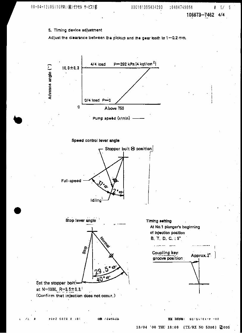
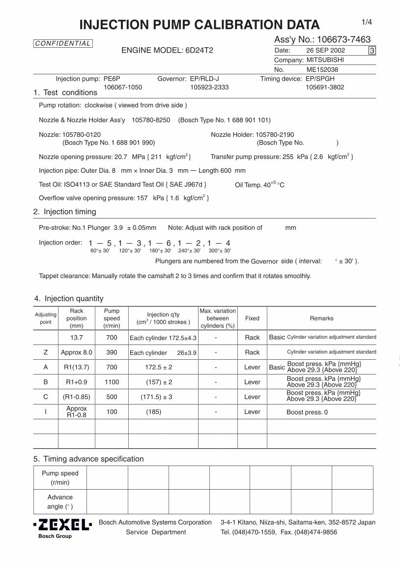
Adjustingpoint
Rackposition
(mm)
Pumpspeed(r/min)
Injection q'ty(cm3 / 1000 strokes )
Max. variationbetween
cylinders (%)Fixed Remarks
13.7 700 - Rack
Z Approx 8.0 390 - Rack
A R1(13.7) 700 172.5 ± 2 - Lever
B R1+0.9 1100 (157) ± 2 - Lever
C (R1-0.85) 500 (171.5) ± 3 - Lever
I ApproxR1-0.8 100 (185) - Lever
Injection order:
Pump speed(r/min)
Advanceangle (° )
4. Injection quantity
5. Timing advance specification
Bosch Automotive Systems Corporation
Service Department
3-4-1 Kitano, Niiza-shi, Saitama-ken, 352-8572 Japan
Tel. (048)470-1559, Fax. (048)474-9856
Company:
Ass'y No.: 106673-7463ENGINE MODEL: 6D24T2
No. Governor: EP/RLD-J Timing device: EP/SPGH
1. Test conditions
Date:
Pump rotation: clockwise ( viewed from drive side )
Injection pump: PE6P105923-2333 105691-3802
kgf/cm2 }
2. Injection timing
Pre-stroke: No.1 Plunger 3.9 ± 0.05mm mm
Plungers are numbered from the ° ± 30' ).
CONFIDENTIAL
INJECTION PUMP CALIBRATION DATA
26 SEP 2002
ME152038
106067-1050
Injection pipe: Outer Dia. 8 mm × Inner Dia. 3 mm Length 600 mm
Nozzle opening pressure: 20.7 MPa { 211 kgf/cm2 }
Nozzle: 105780-0120 Nozzle Holder: 105780-2190(Bosch Type No. 1 688 901 990) (Bosch Type No. )
Nozzle & Nozzle Holder Ass'y: 105780-8250 (Bosch Type No. 1 688 901 101)
Overflow valve opening pressure: 157 kPa { 1.6 kgf/cm2 }
Test Oil: ISO4113 or SAE Standard Test Oil { SAE J967d } Oil Temp. 40+5 °C
side ( interval:
3
Transfer pump pressure: 255 kPa { 2.6
Note: Adjust with rack position of
1 5 , 1 3 , 1 6 , 1 2 , 1 460°± 30' 120°± 30' 180°± 30' 240°± 30' 300°± 30'
MITSUBISHI
Governor
1/4
Tappet clearance: Manually rotate the camshaft 2 to 3 times and confirm that it rotates smoothly.
Boost press. kPa {mmHg}Above 29.3 {Above 220}
Boost press. 0
Cylinder variation adjustment standardEach cylinder 172.5±4.3
(qA-27 qB qA-19)
Each cylinder 26±3.9
Basic
Cylinder variation adjustment standard
Basic
Boost press. kPa {mmHg}Above 29.3 {Above 220}
Boost press. kPa {mmHg}Above 29.3 {Above 220}Boost press. kPa {mmHg}Above 29.3 {Above 220}
Approx. R1-0.8
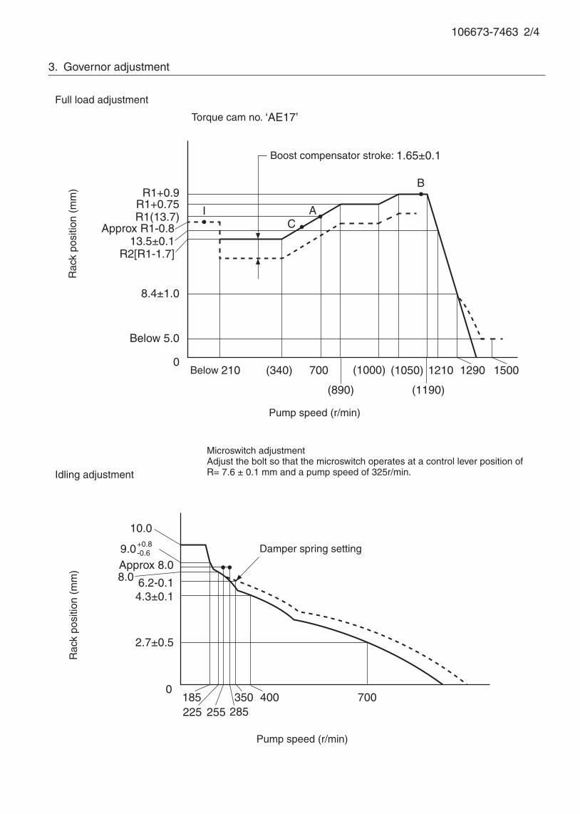
106673-7463 2/4
3. Governor adjustment
0185225 285
700
Rac
k po
sitio
n (m
m)
Pump speed (r/min)
10.0
9.0+0.8-0.6
Approx R1-0.8
R1+0.75
0Below 210 (340) (1050)
A
B
Rac
k po
sitio
n (m
m)
Pump speed (r/min)
Torque cam no. ‘AE17’
R1+0.9
R1(13.7)
700
(890)
(1000)
(1190)
1210
400
2.7±0.5
8.0Approx 8.0
Full load adjustment
Idling adjustment
Boost compensator stroke: 1.65±0.1
R2[R1-1.7]
8.4±1.0
1290
6.2-0.1
CI
13.5±0.1
Below 5.0
1500
4.3±0.1
255350
Damper spring setting
Microswitch adjustment Adjust the bolt so that the microswitch operates at a control lever position ofR= 7.6 ± 0.1 mm and a pump speed of 325r/min.
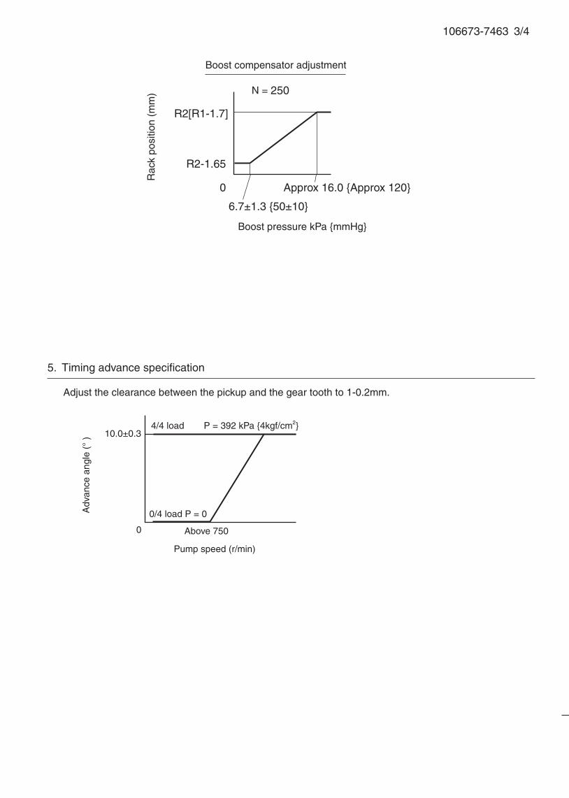
106673-7463 3/4
5. Timing advance specification
Pump speed (r/min)
10.0±0.3
0 Above 750
0/4 load P = 0
4/4 load P = 392 kPa {4kgf/cm2}
Adv
ance
ang
le (
° )
Adjust the clearance between the pickup and the gear tooth to 1-0.2mm.
R2[R1-1.7]
R2-1.65
0
6.7±1.3 {50±10}
Approx 16.0 {Approx 120}
N = 250
Rac
k po
sitio
n (m
m)
Boost pressure kPa {mmHg}
Boost compensator adjustment
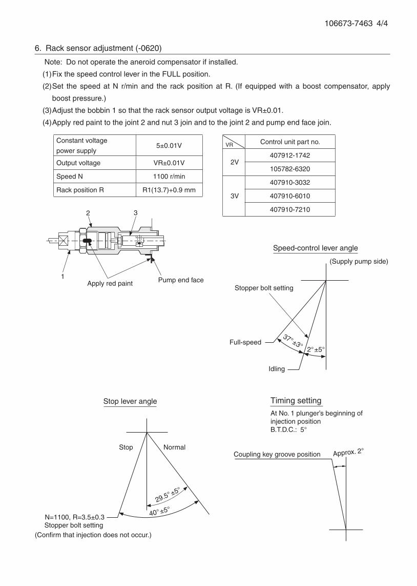
106673-7463 4/4
6. Rack sensor adjustment (-0620)
Note: Do not operate the aneroid compensator if installed.
(1) Fix the speed control lever in the FULL position.
(2) Set the speed at N r/min and the rack position at R. (If equipped with a boost compensator, apply
boost pressure.)
(3) Adjust the bobbin 1 so that the rack sensor output voltage is VR±0.01.
(4) Apply red paint to the joint 2 and nut 3 join and to the joint 2 and pump end face join.
1
2 3
Constant voltage
power supply5±0.01V
Output voltage VR±0.01V
Speed N 1100 r/min
Rack position R R1(13.7)+0.9 mm
VR Control unit part no.
2V407912-1742
105782-6320
3V
407910-3032
407910-6010
407910-7210
Apply red paint Pump end face
Speed-control lever angle
Idling
Full-speed
Stopper bolt setting
(Supply pump side)
2°±5°
37°±3°
Stop lever angle
Stop Normal
(Confirm that injection does not occur.)
40°±5°29.5°±5°
Stopper bolt settingN=1100, R=3.5±0.3
Coupling key groove position Approx. 2°
Timing setting
At No. 1 plunger’s beginning of injection positionB.T.D.C.: 5°
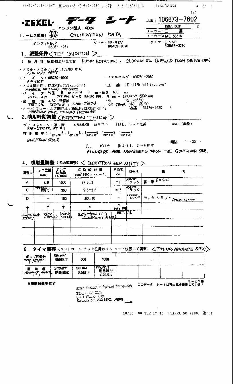
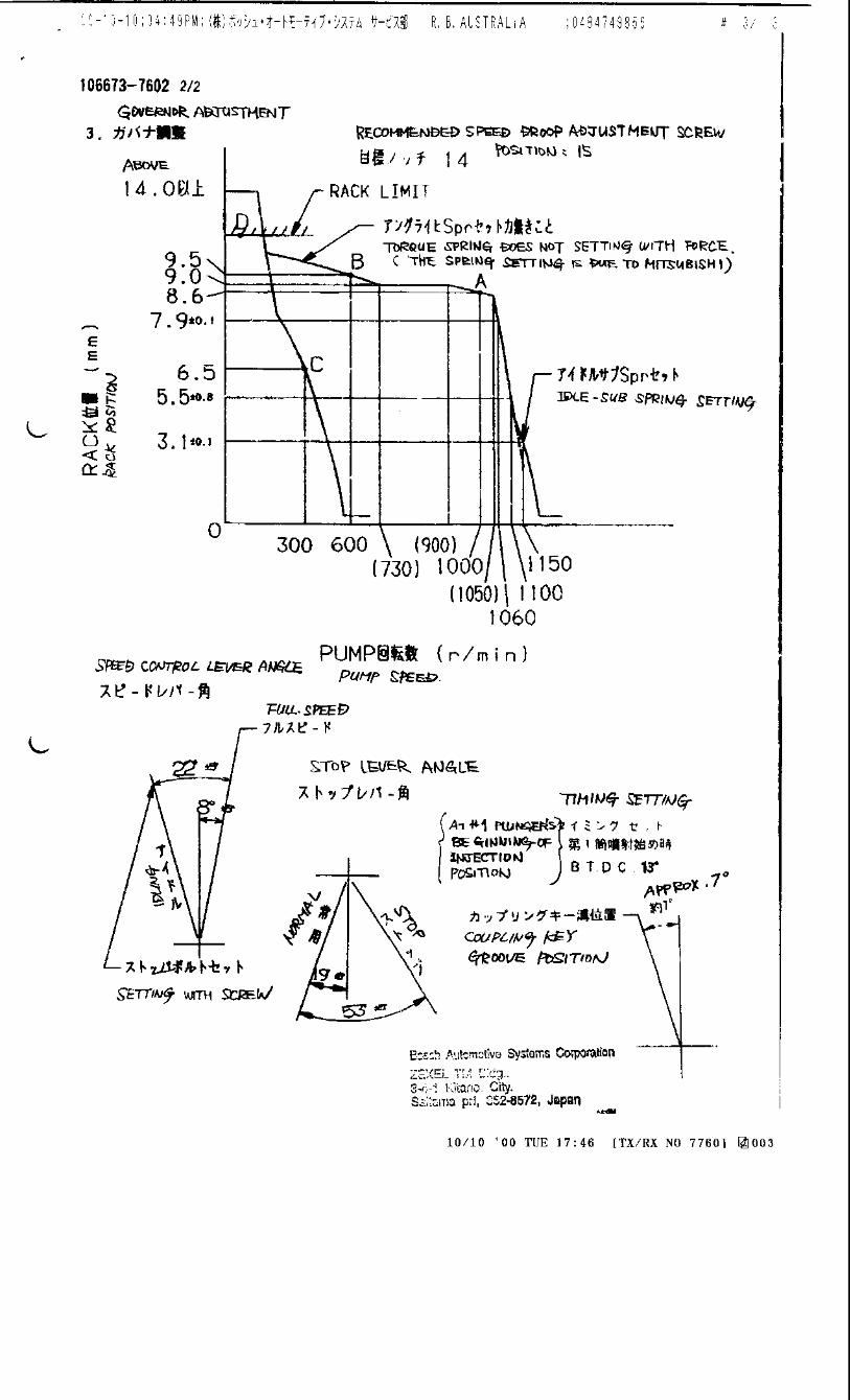
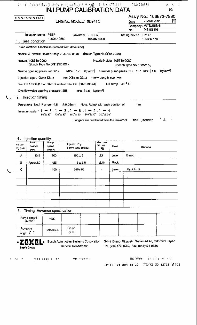
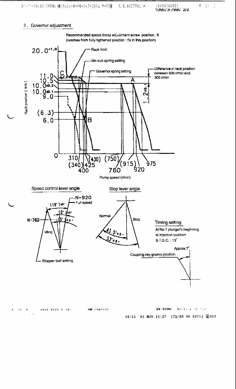

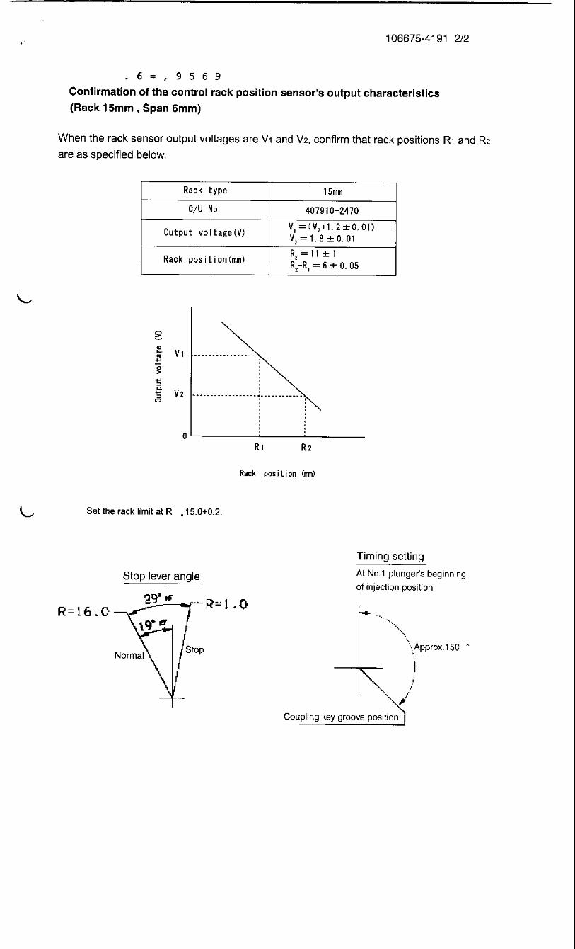
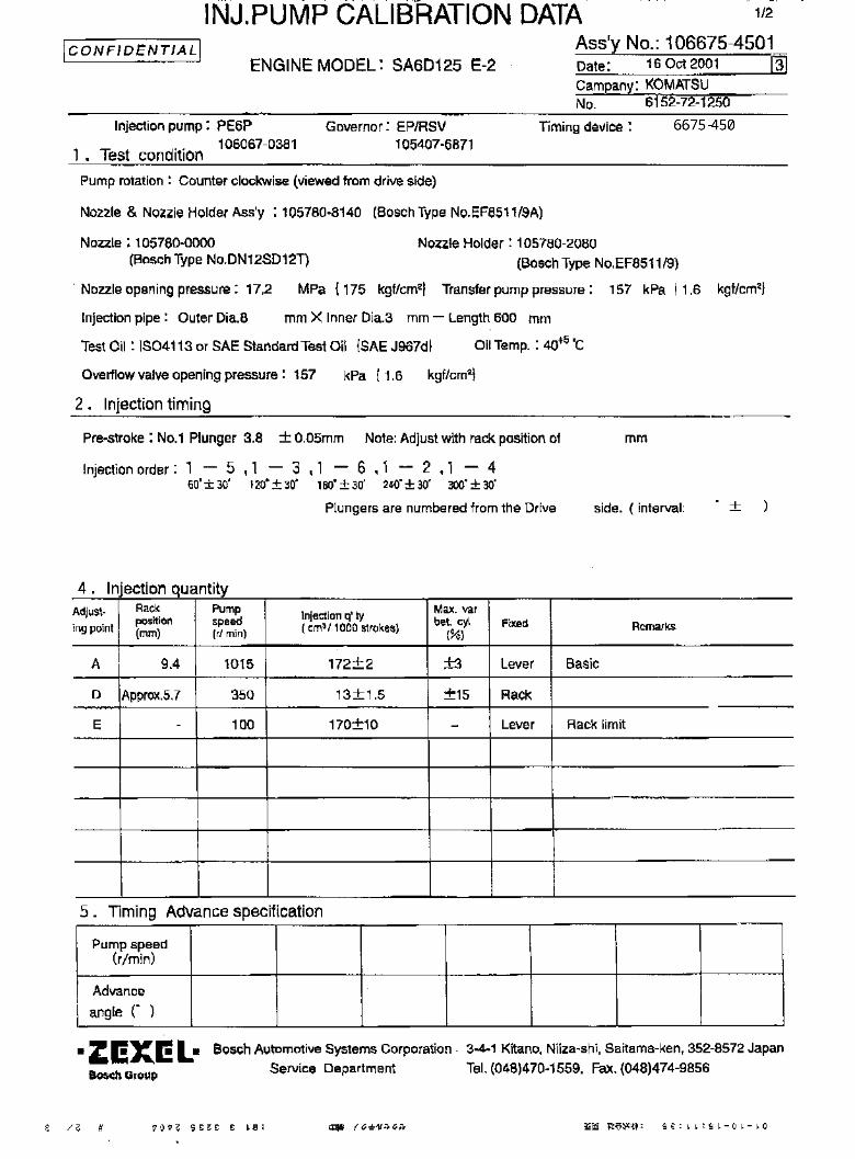
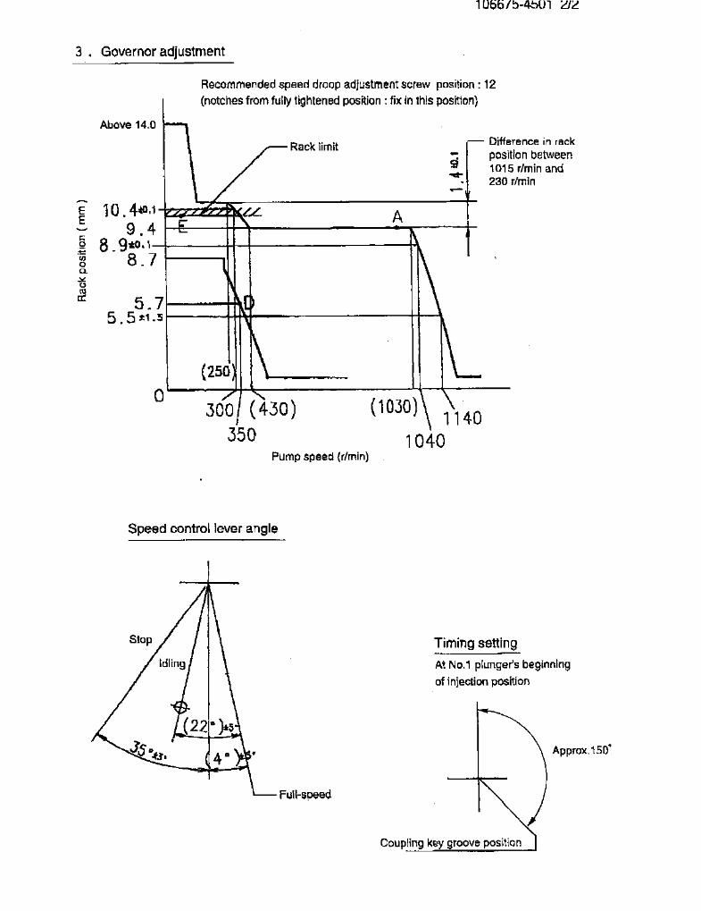
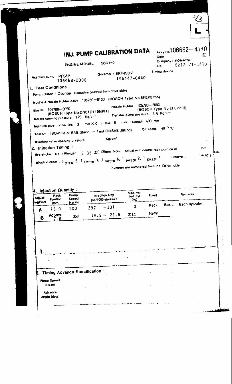
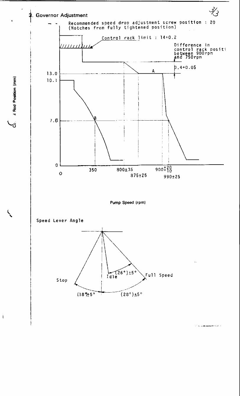

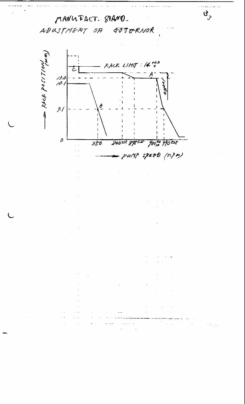
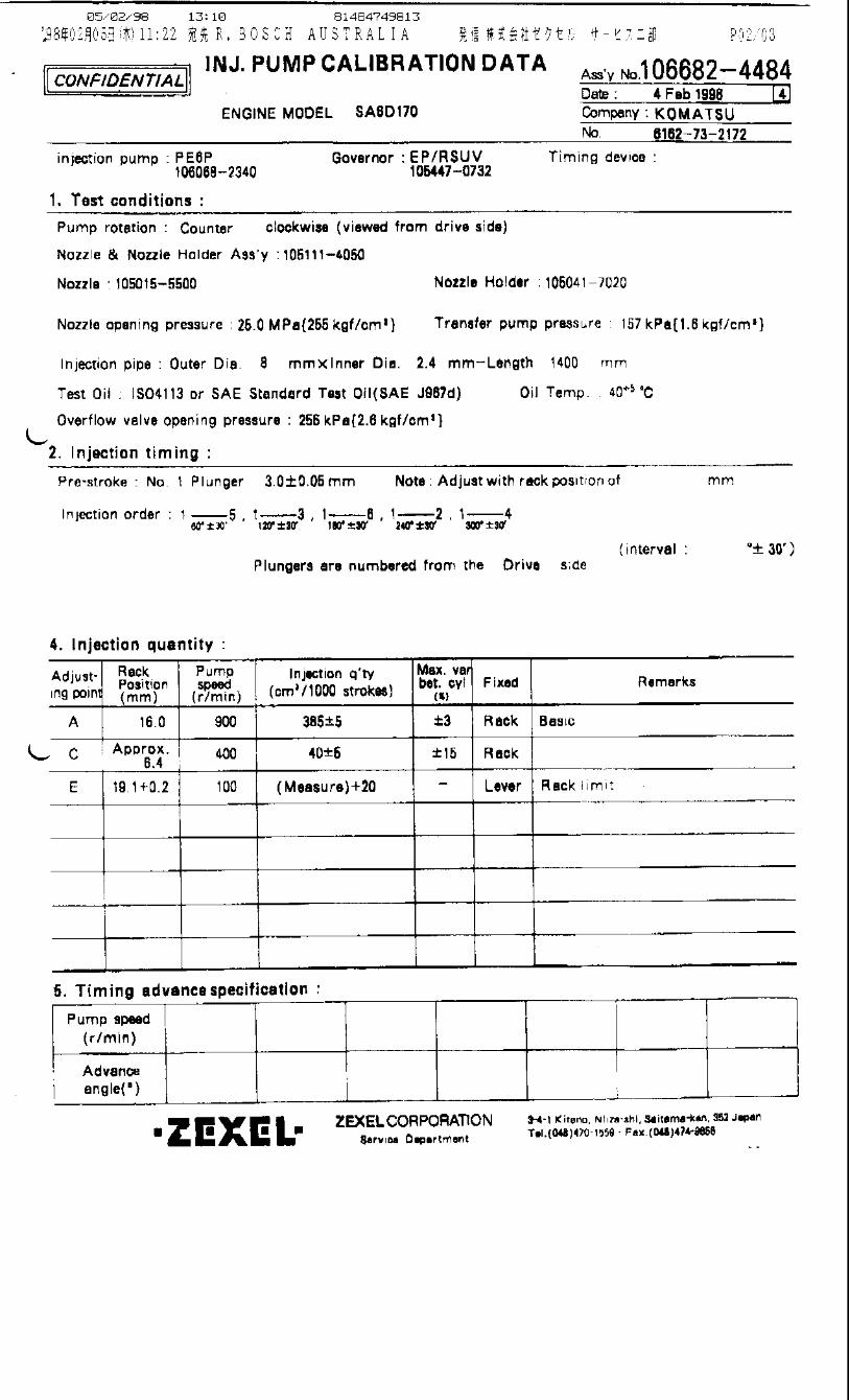
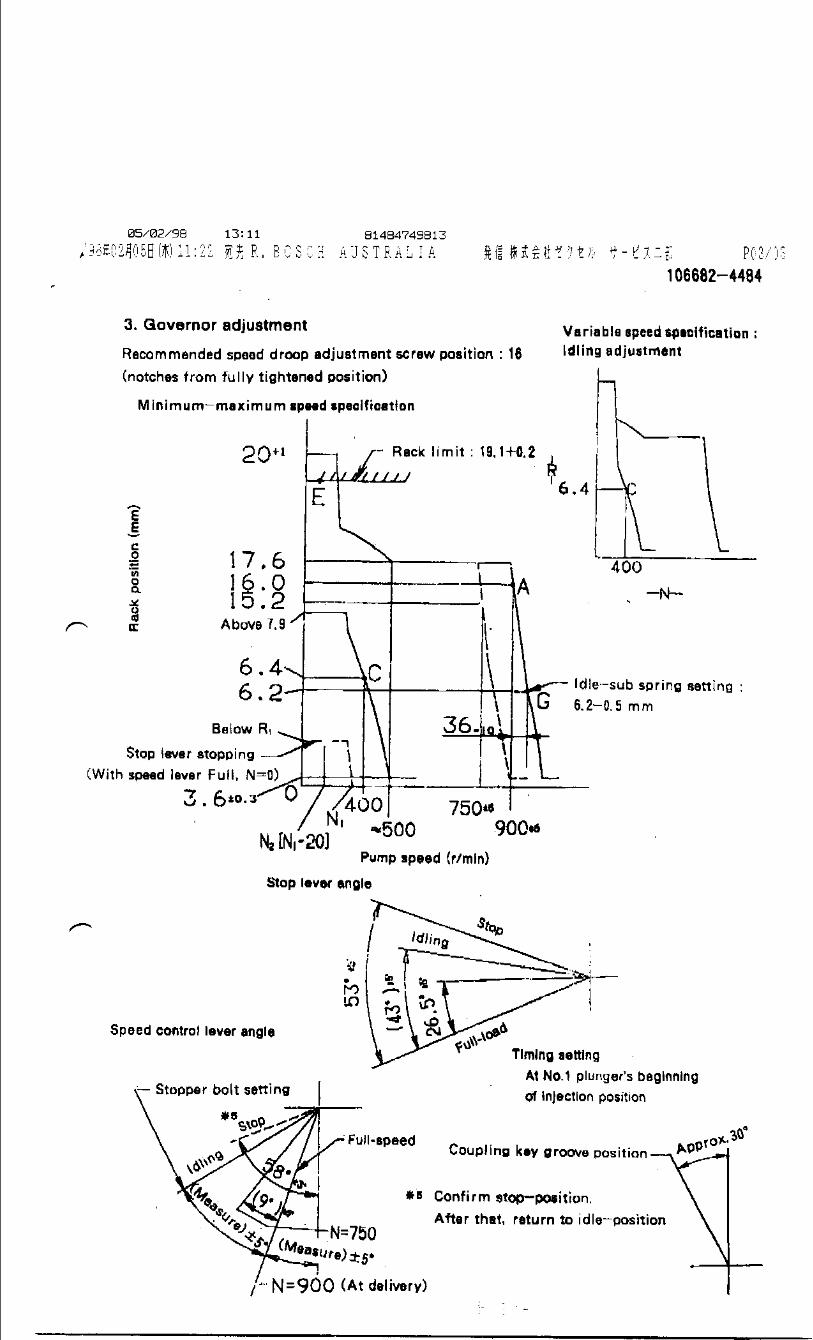


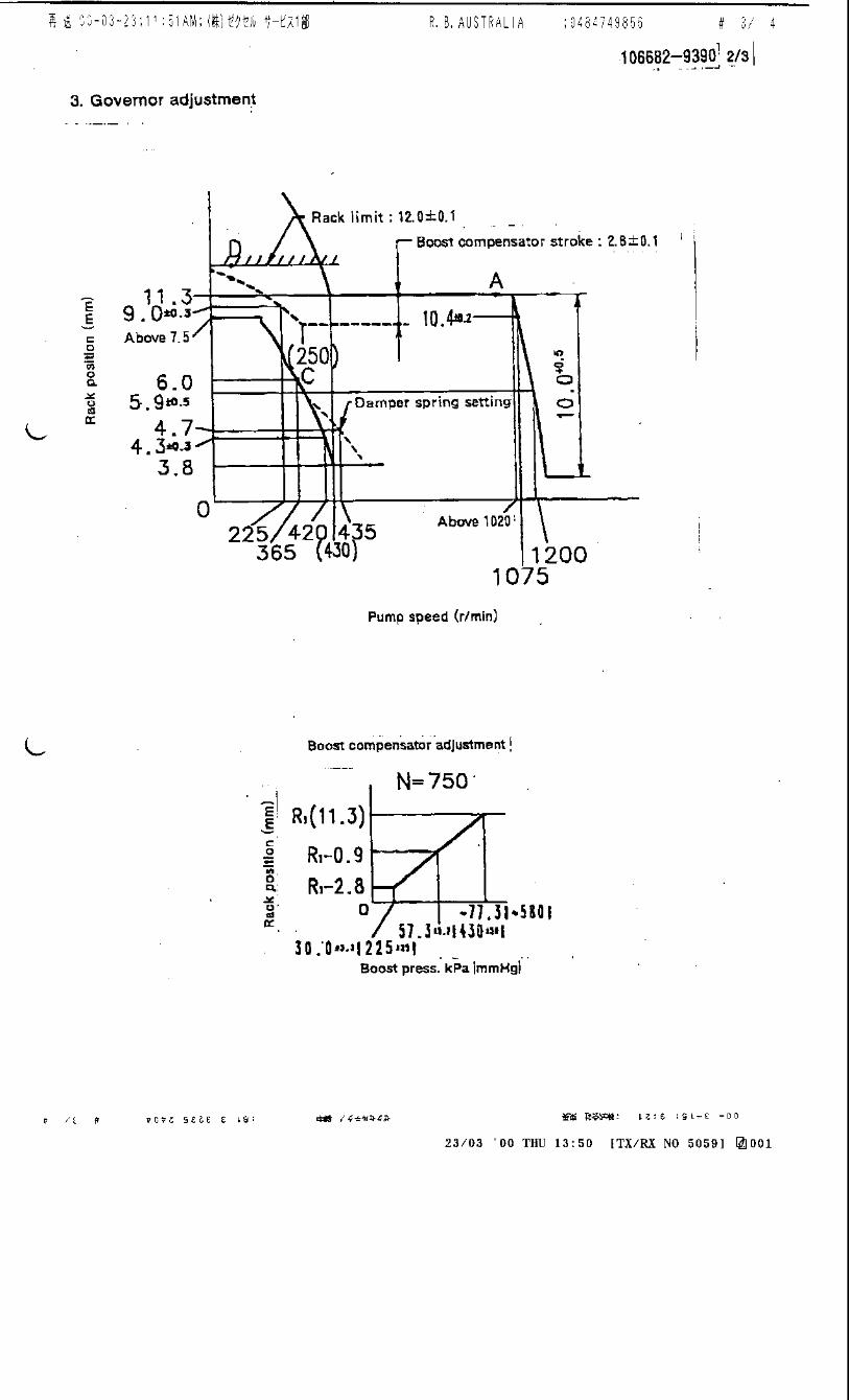
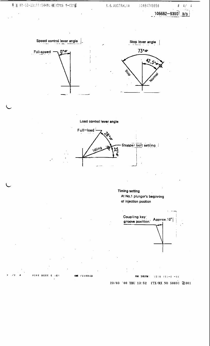
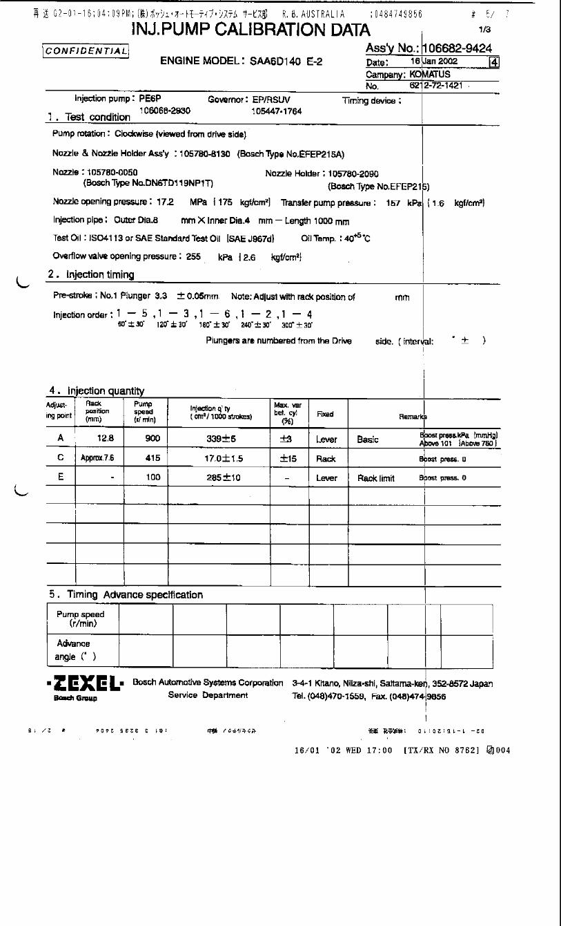

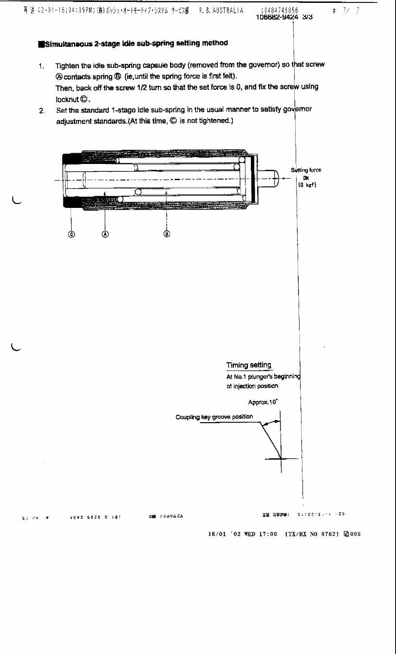
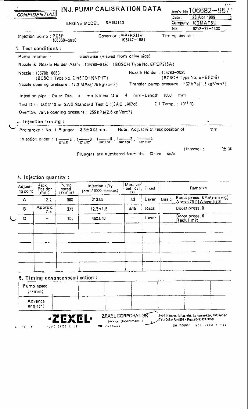
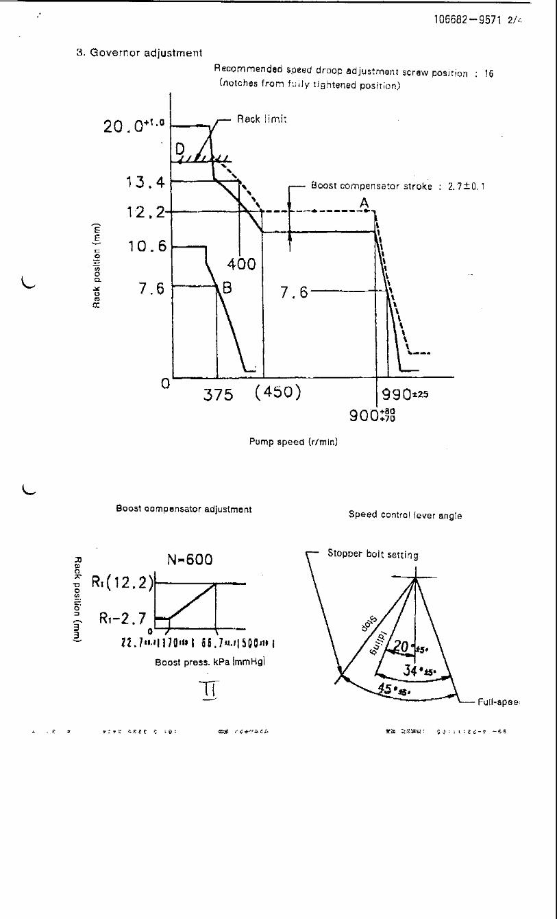
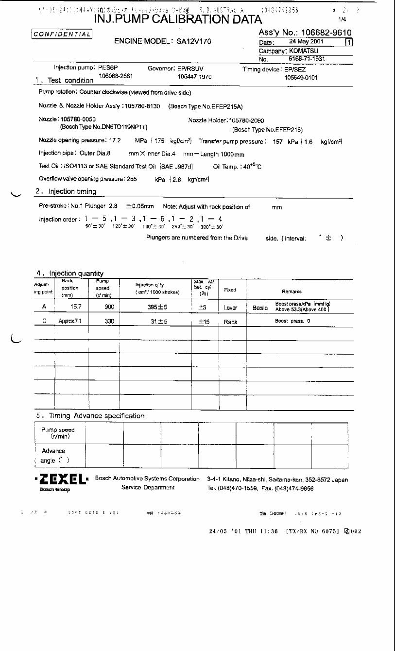
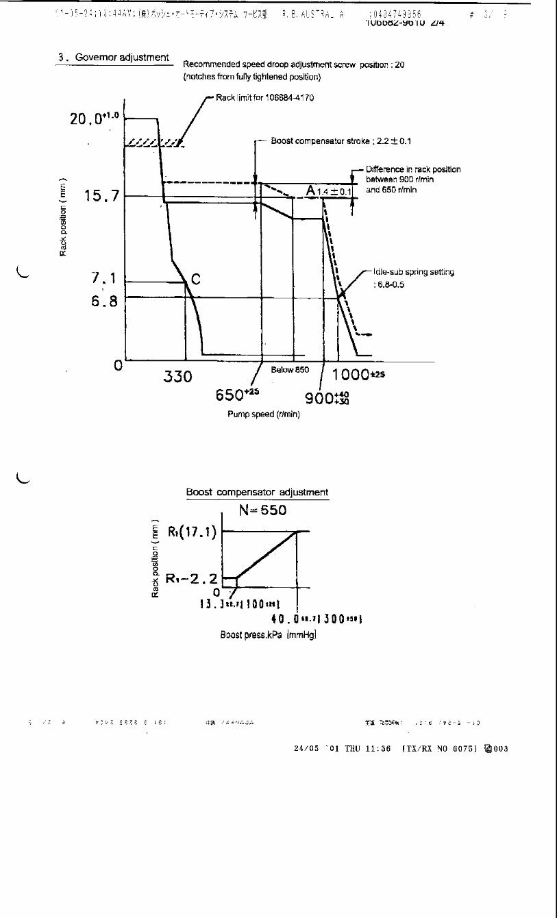
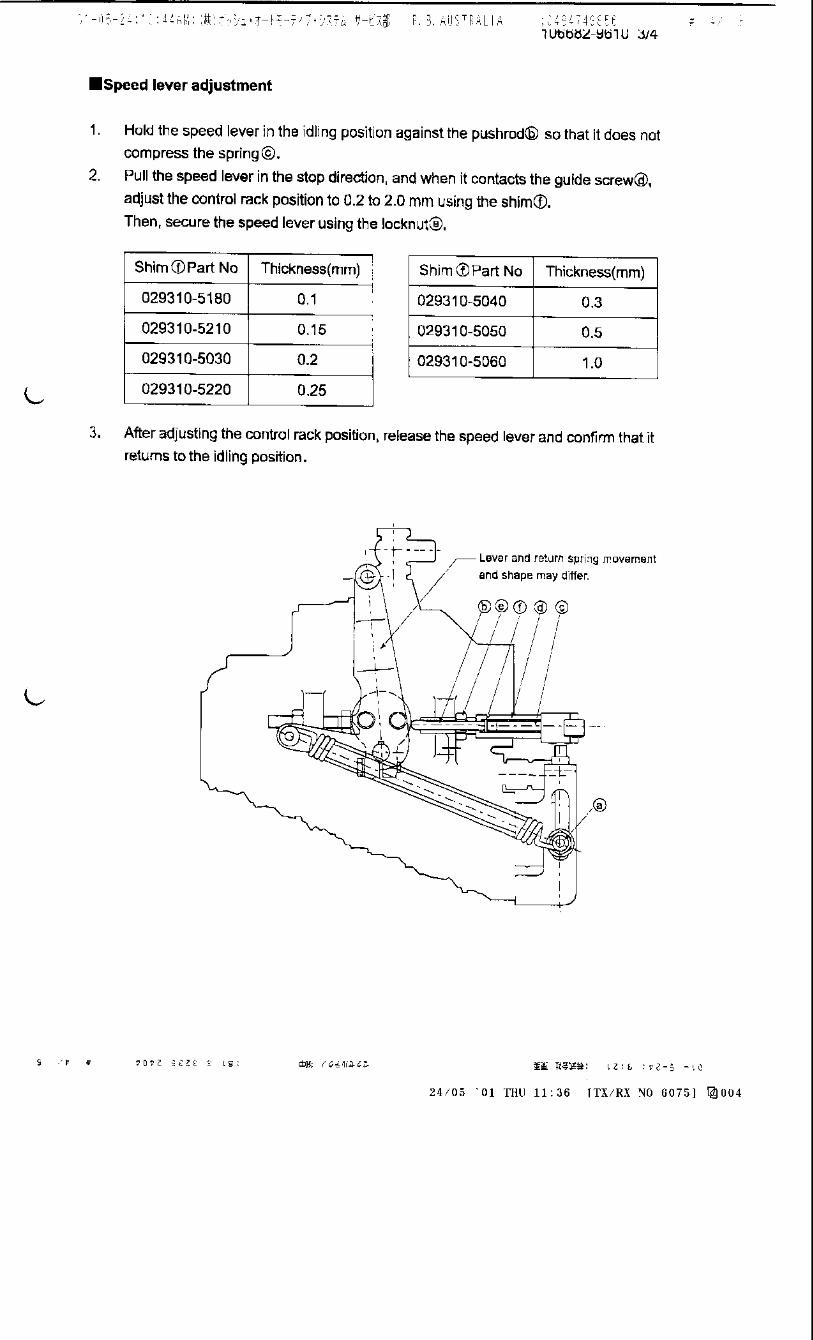
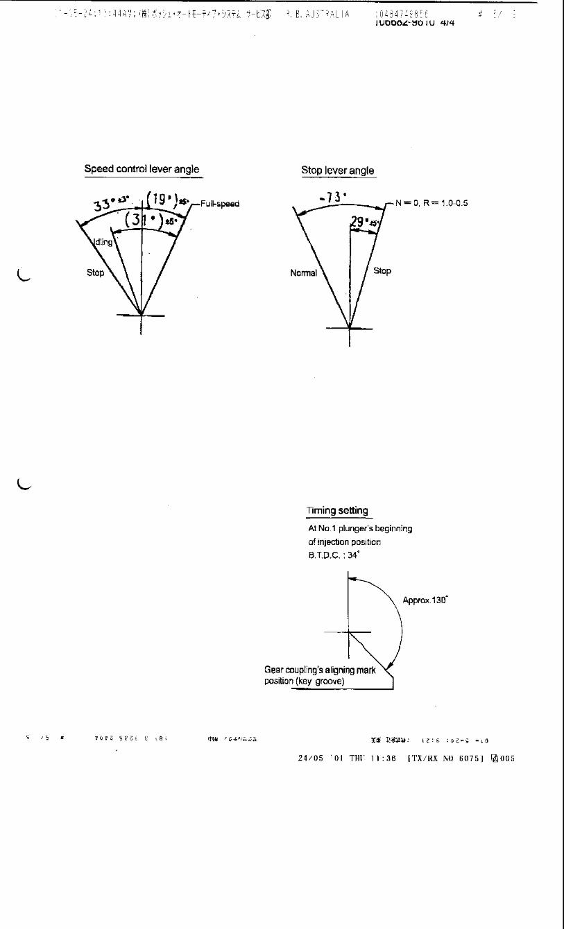
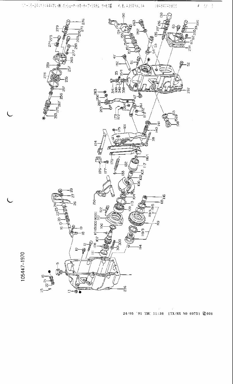
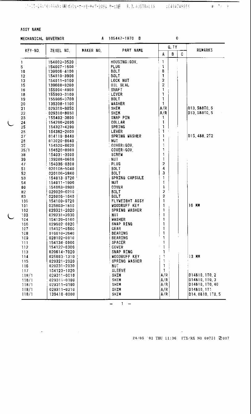
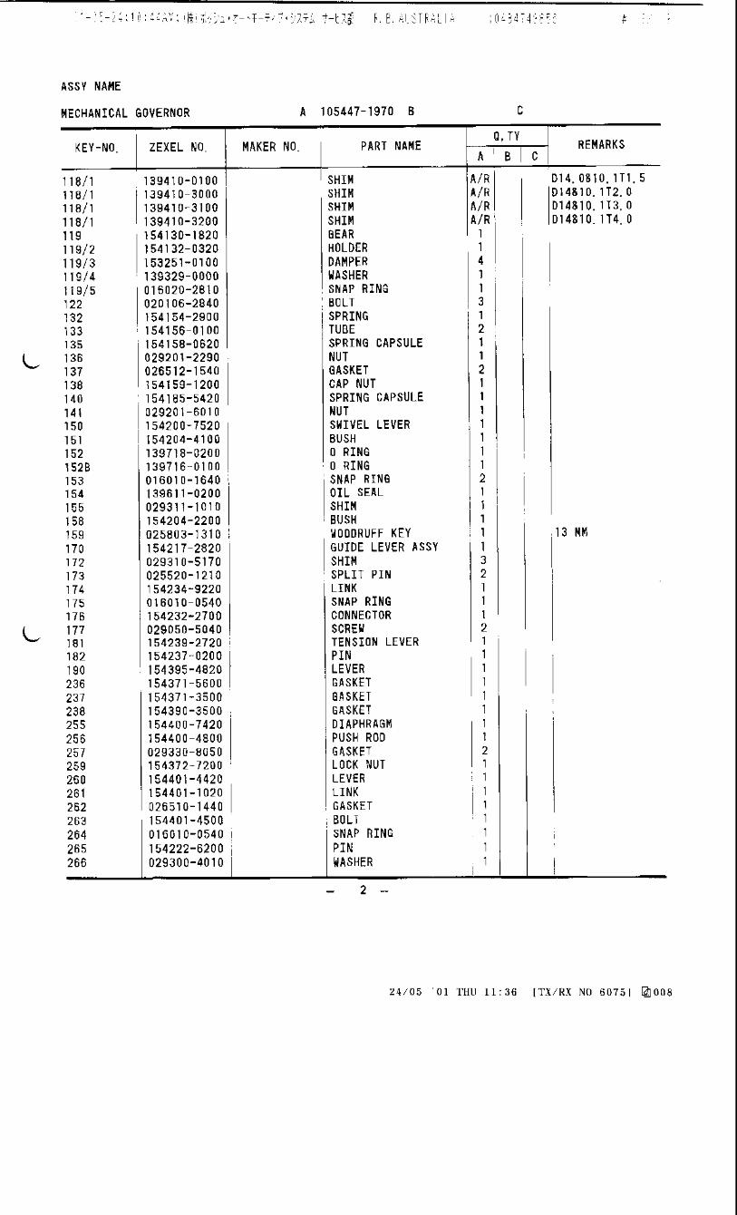
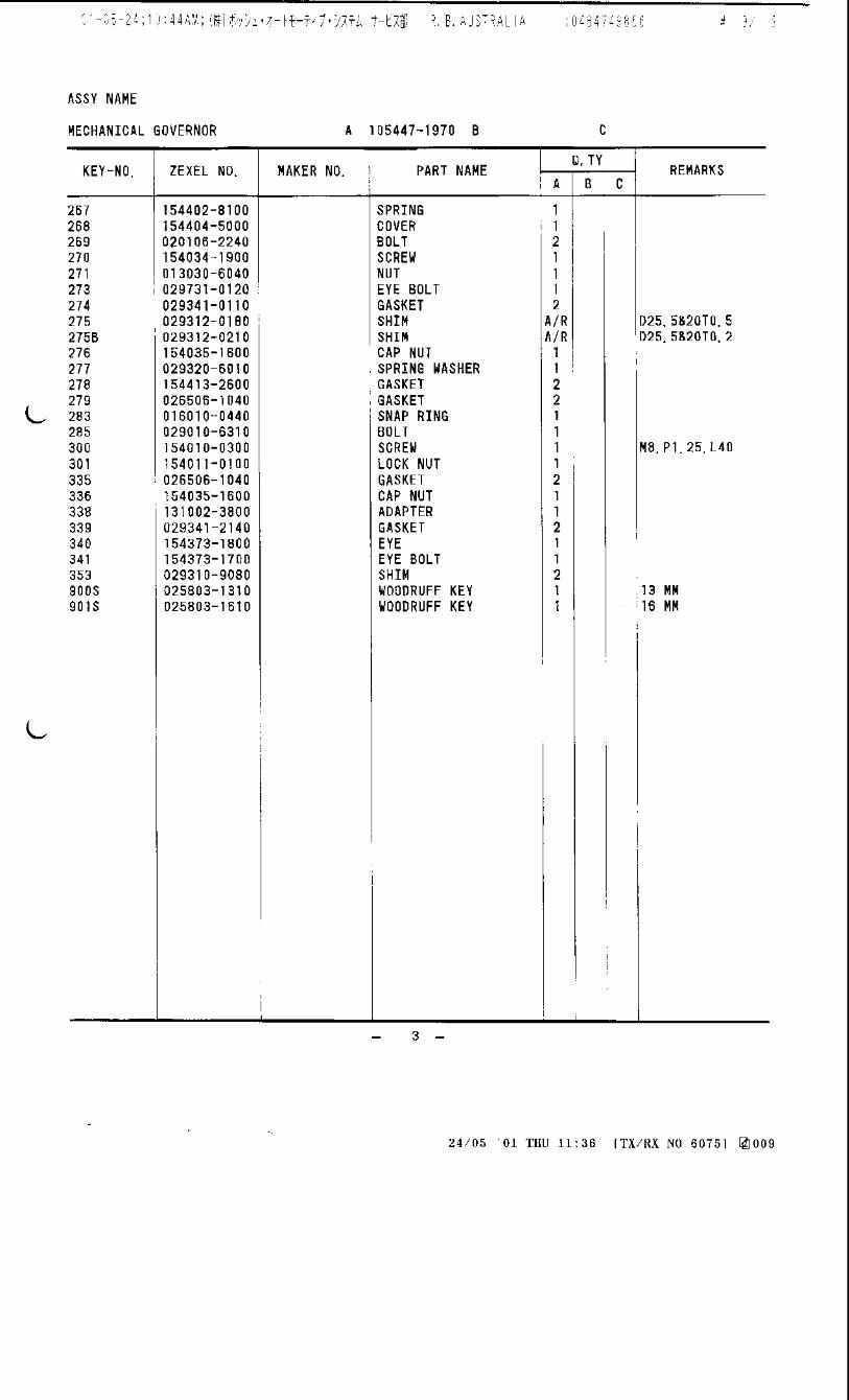
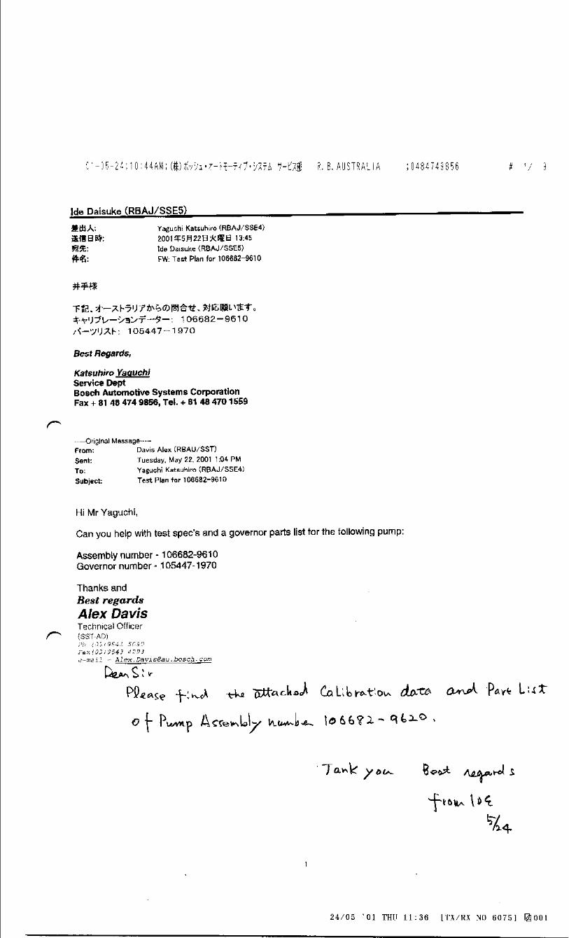
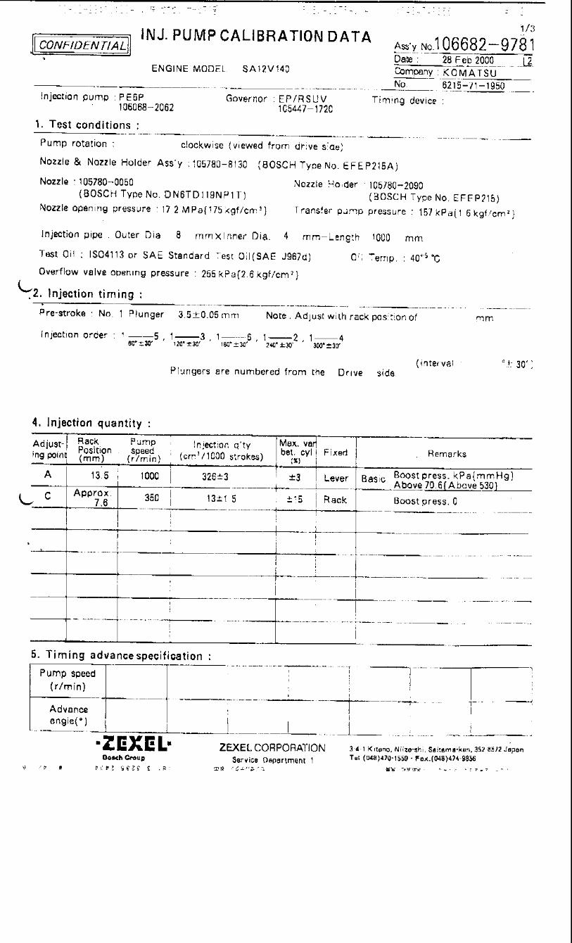

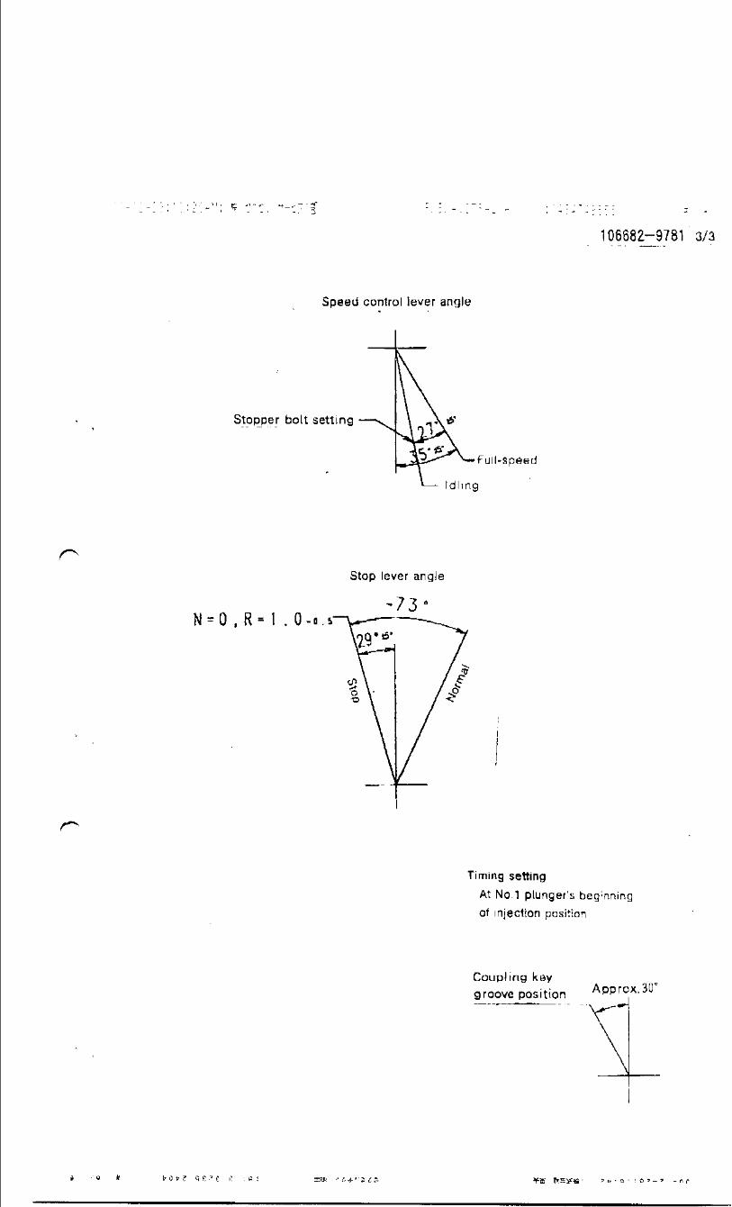
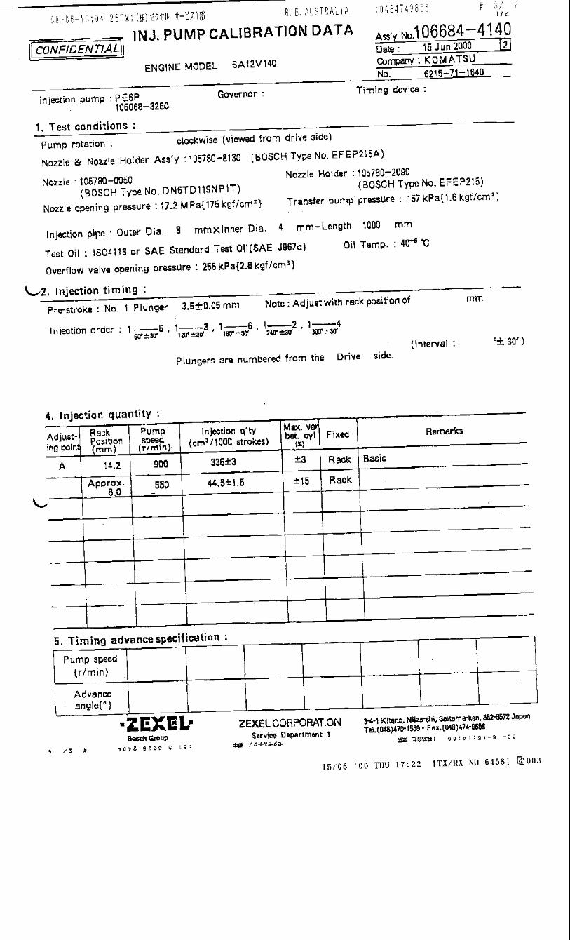

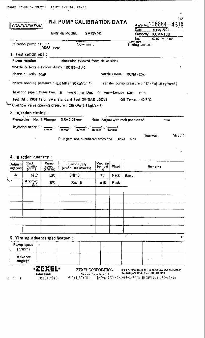

Oil temperature: 40+5 °C
Adjustingpoint
Rackposition
(mm)
Pumpspeed(r/min)
Injection quantity(cm3/1000 strokes)
Max. variationbetween
cylinders (%)Fixed Remarks
A 13.6 1025 313 ± 9 ± 3 Rack Basic Rack limit
B Approx 6.5 400 30 ± 3 ± 10 Rack
Injection order:
Pump speed(r/min)
Advanceangle (° )
3. Injection quantity
4. Timing advance specification
Company:
Assy No.: 106684-4460ENGINE MODEL: S6A3
No. Governor: Timing device:
1. Test conditions
Date:
Pump rotation: counter clockwise (viewed from drive side)
Injection pump: PE6P
kgf/cm2}
2. Injection timing
Pre-stroke: No.1 plunger 3.5 ± 0.05mm mm
Plungers are numbered from the Opposite Drive ° ± 30').
CONFIDENTIAL
INJECTION PUMP CALIBRATION DATA
31 Oct 2007
35A65-11070
106068-4030
Injection pipe: outer dia. 6 mm × inner dia. 2.2mm length 1215 mm
Nozzle opening pressure: 29.4 MPa {300 kgf/cm2}
Nozzle: 105025-2680 Nozzle holder: 105040-5020(Bosch type no. DLLA158SM268) (Bosch type no. )
Nozzle & nozzle holder assy: 105110-6000 (Bosch type no. )
Test oil: ISO4113 or SAE standard test oil {SAE J967d}
side (interval:
1
Transfer pump pressure: 255 kPa {2.6
Note: Adjust with rack position of R=A(13.6)
1 5 , 1 3 , 1 6 , 1 2 , 1 460°± 30' 120°± 30' 180°± 30' 240°± 30' 300°± 30'
1/2
Tappet clearance: Manually rotate the camshaft 2 to 3 times and confirm that it rotates smoothly.
Overflow valve opening pressure: 255 ± 34 kPa {2.6 ± 0.35 kgf/cm2}
MITSUBISHI. HEAVYTEMPORARILY
Bosch CorporationAutomotive Aftermarket Division
3-4-1 Kitano, Niiza-shi, Saitama-ken, 352-8572, JAPAN
Tel. 81-48-475-2521 Fax. 81-48-475-2520
106684-4460 2/2
Coupling key groove position
Timing setting
At No. 1 plunger’s beginning of injection position
Appr
ox. 1
10°
Oil temperature: 40+5 °C
Adjustingpoint
Rackposition
(mm)
Pumpspeed(r/min)
Injection quantity(cm3/1000 strokes)
Max. variationbetween
cylinders (%)Fixed Remarks
A 13.6 1025 313 ± 9 ± 3 Rack Basic Rack limit
B Approx 6.5 400 30 ± 3 ± 10 Rack
Injection order:
Pump speed(r/min)
Advanceangle (° )
3. Injection quantity
4. Timing advance specification
Company:
Assy No.: 106684-4461ENGINE MODEL: S6A3
No. Governor: Timing device:
1. Test conditions
Date:
Pump rotation: counter clockwise (viewed from drive side)
Injection pump: PE6P
kgf/cm2}
2. Injection timing
Pre-stroke: No.1 plunger 3.5 ± 0.05mm mm
Plungers are numbered from opposite the Drive ° ± 30').
CONFIDENTIAL
INJECTION PUMP CALIBRATION DATA
20 Sep 2007
35A65-11070
106068-3462
Injection pipe: outer dia. 6 mm × inner dia. 2.2mm length 1215 mm
Nozzle opening pressure: 29.4 MPa {300 kgf/cm2}
Nozzle: 105025-2680 Nozzle holder: 105040-5020(Bosch type no. DLLA158SM268) (Bosch type no. )
Nozzle & nozzle holder assy: 105110-6000 (Bosch type no. )
Test oil: ISO4113 or SAE standard test oil {SAE J967d}
side (interval:
1
Transfer pump pressure: 255 kPa {2.6
Note: Adjust with rack position of R=A(13.6)
1 5 , 1 3 , 1 6 , 1 2 , 1 460°± 30' 120°± 30' 180°± 30' 240°± 30' 300°± 30'
1/2
Tappet clearance: Manually rotate the camshaft 2 to 3 times and confirm that it rotates smoothly.
Overflow valve opening pressure: 255 ± 34 kPa {2.6 ± 0.35 kgf/cm2}
MITSUBISHI. HEAVYTEMPORARILY
Bosch CorporationAutomotive Aftermarket Division
3-4-1 Kitano, Niiza-shi, Saitama-ken, 352-8572, JAPAN
Tel. 81-48-475-2521 Fax. 81-48-475-2520

106684-4461 2/2
Coupling key groove position
Timing setting
At No. 1 plunger’s beginning of injection position
Approx. 110°
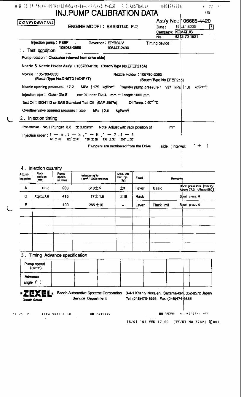
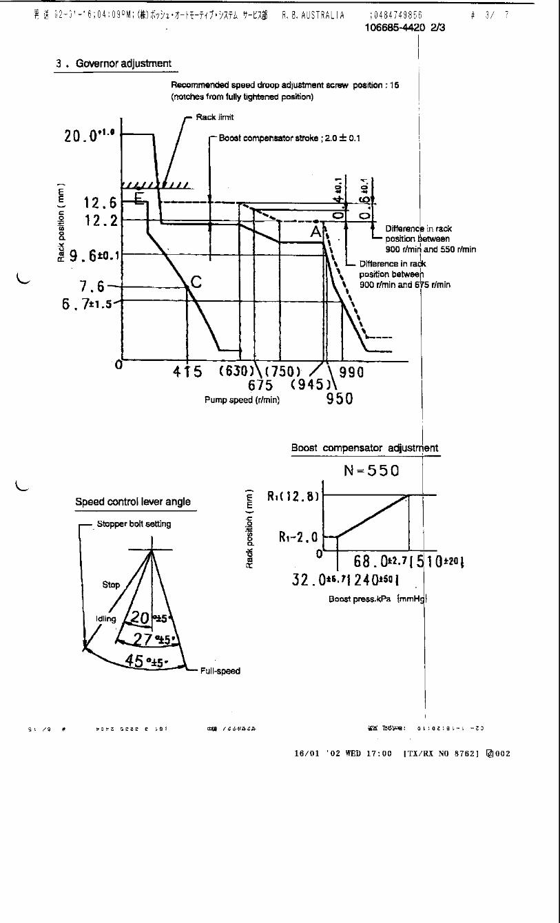

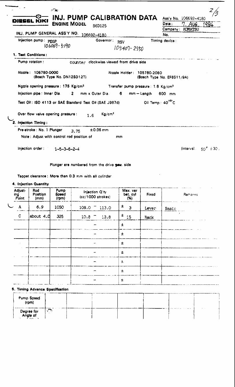
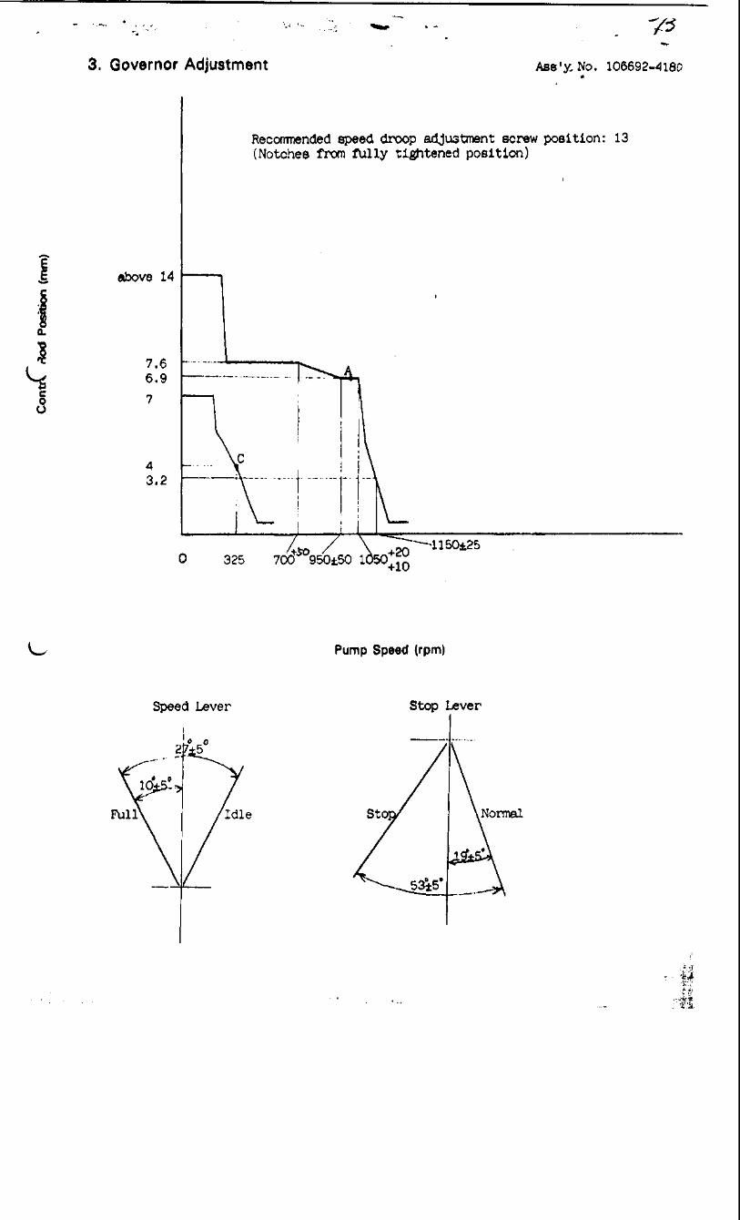
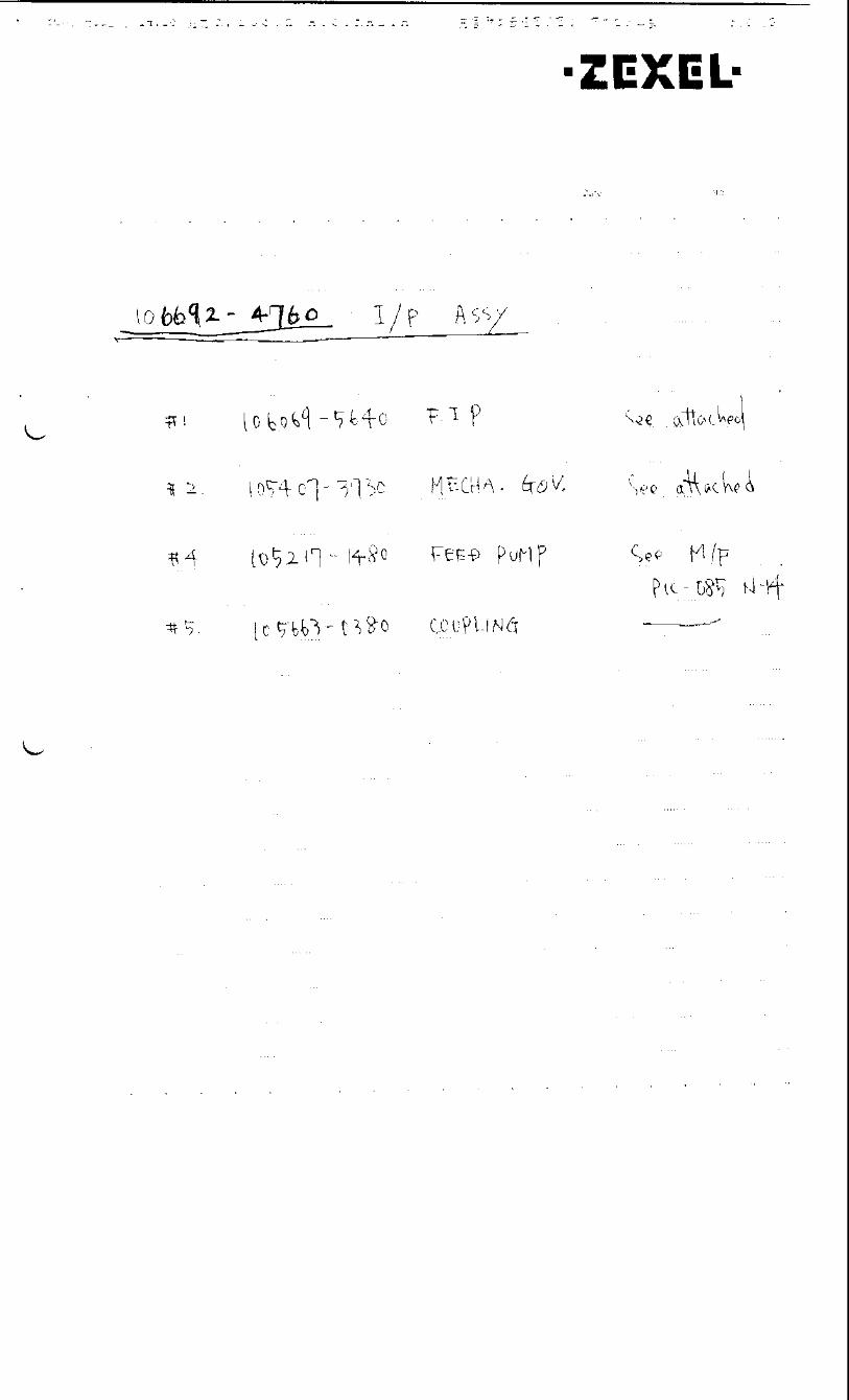
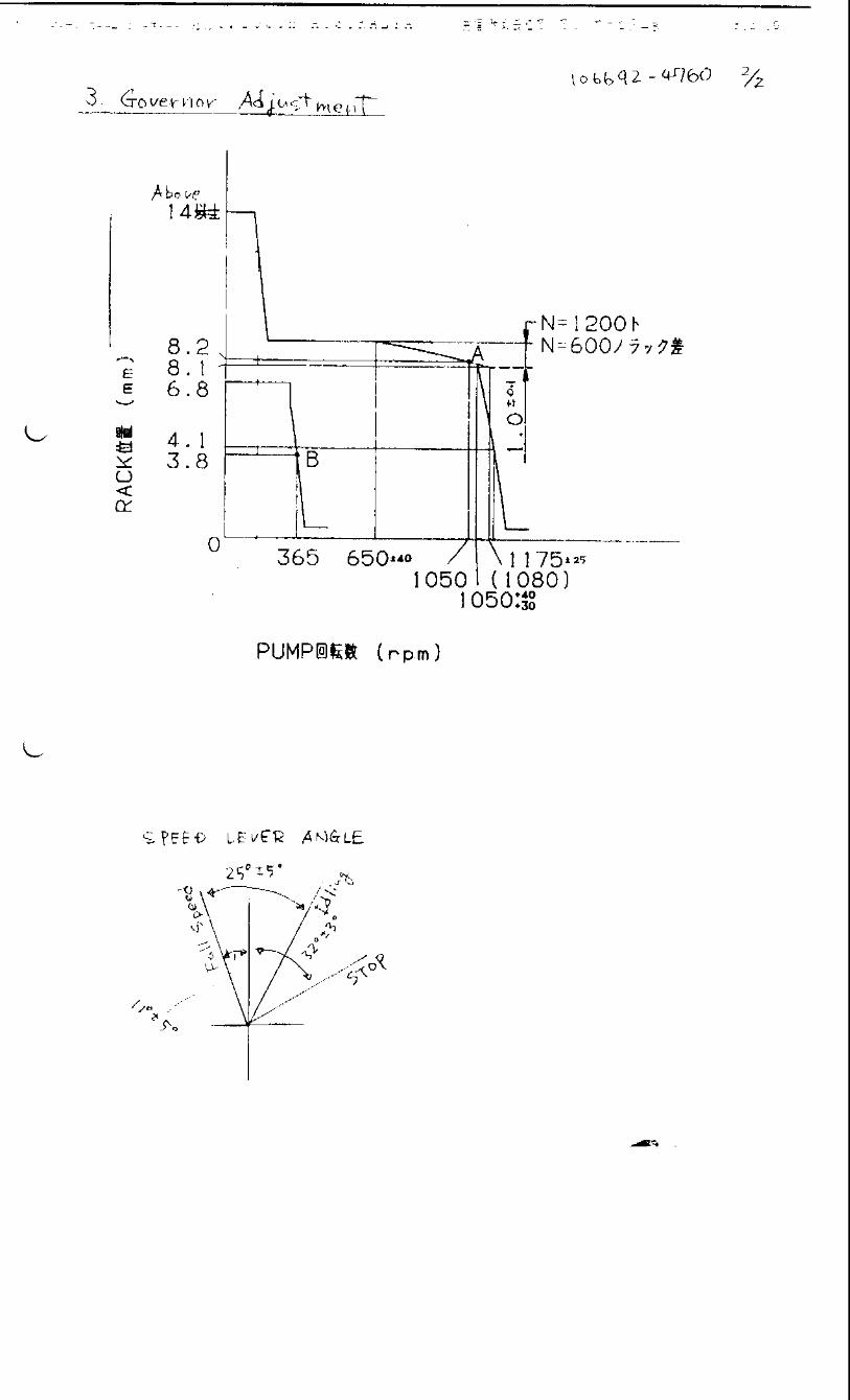
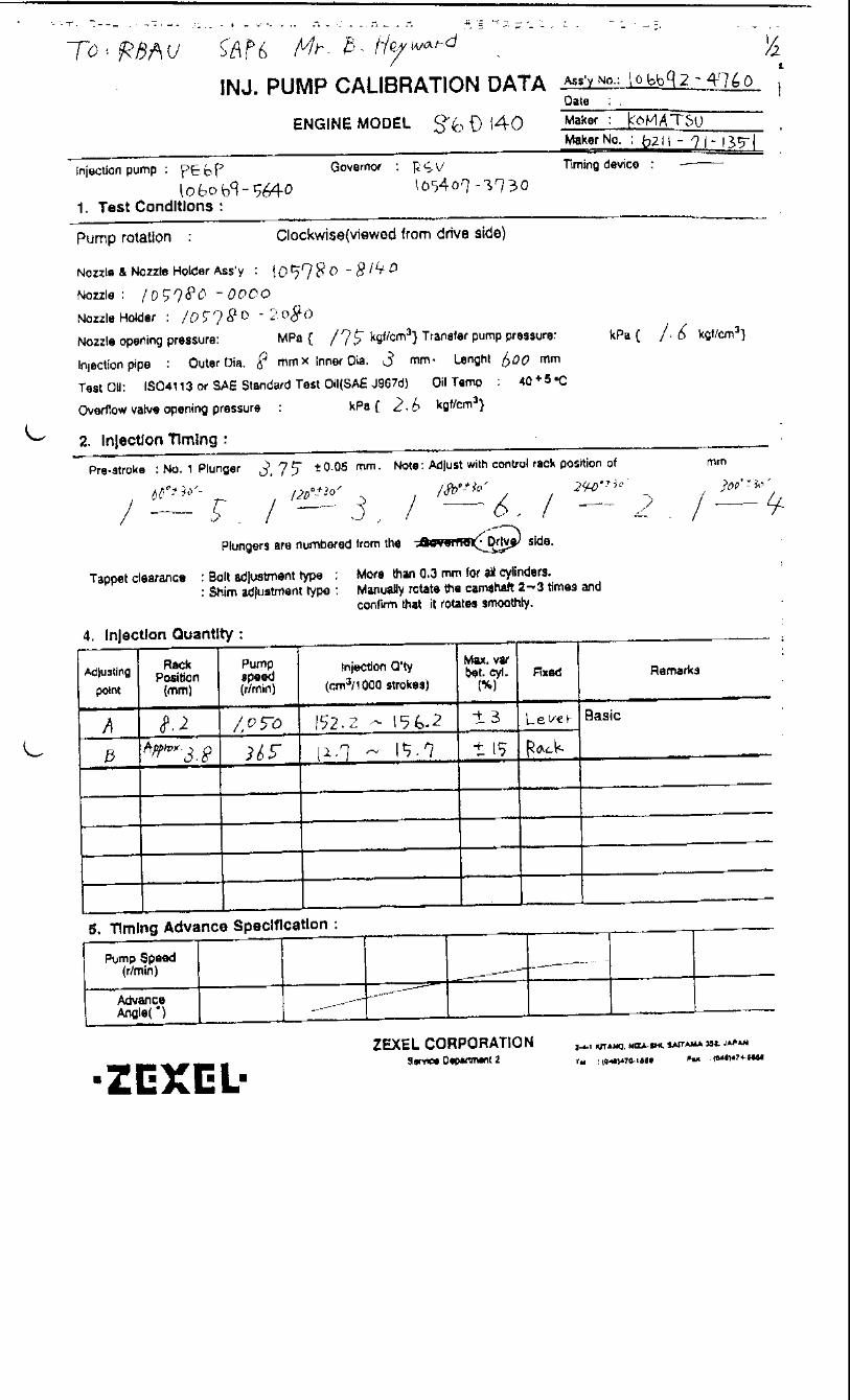
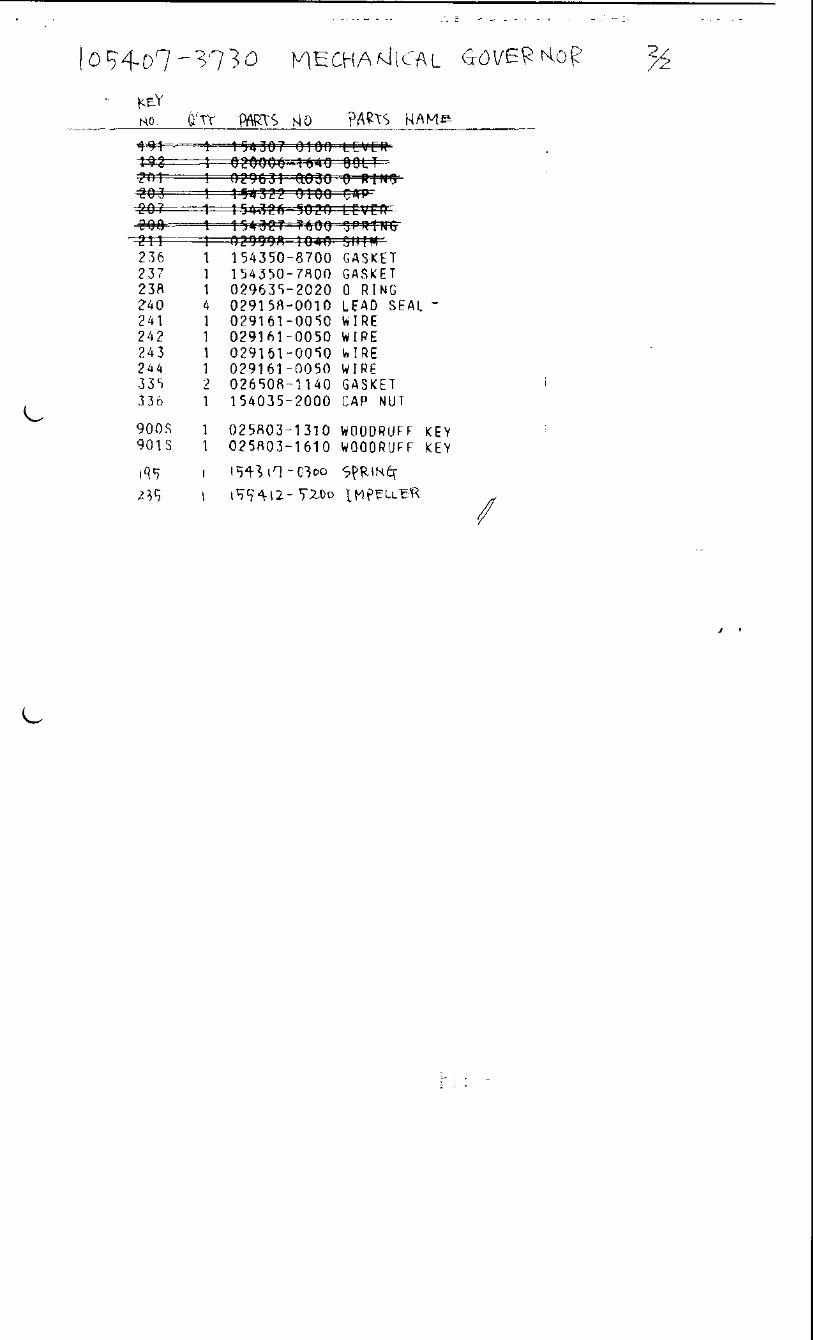
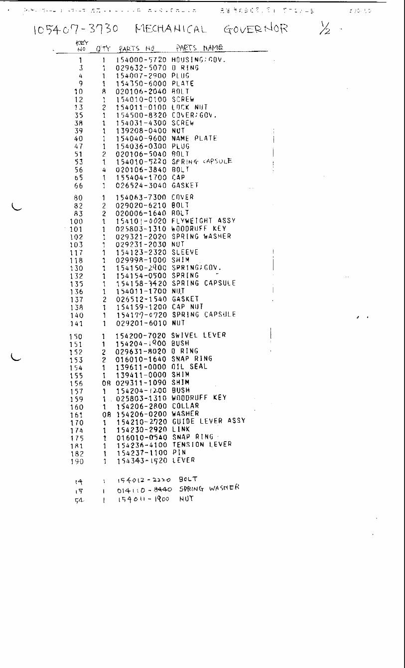
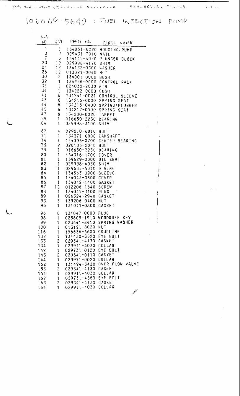
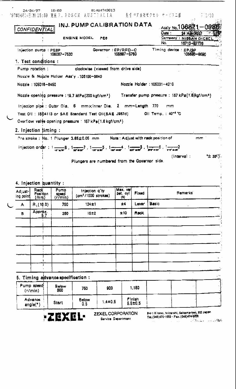
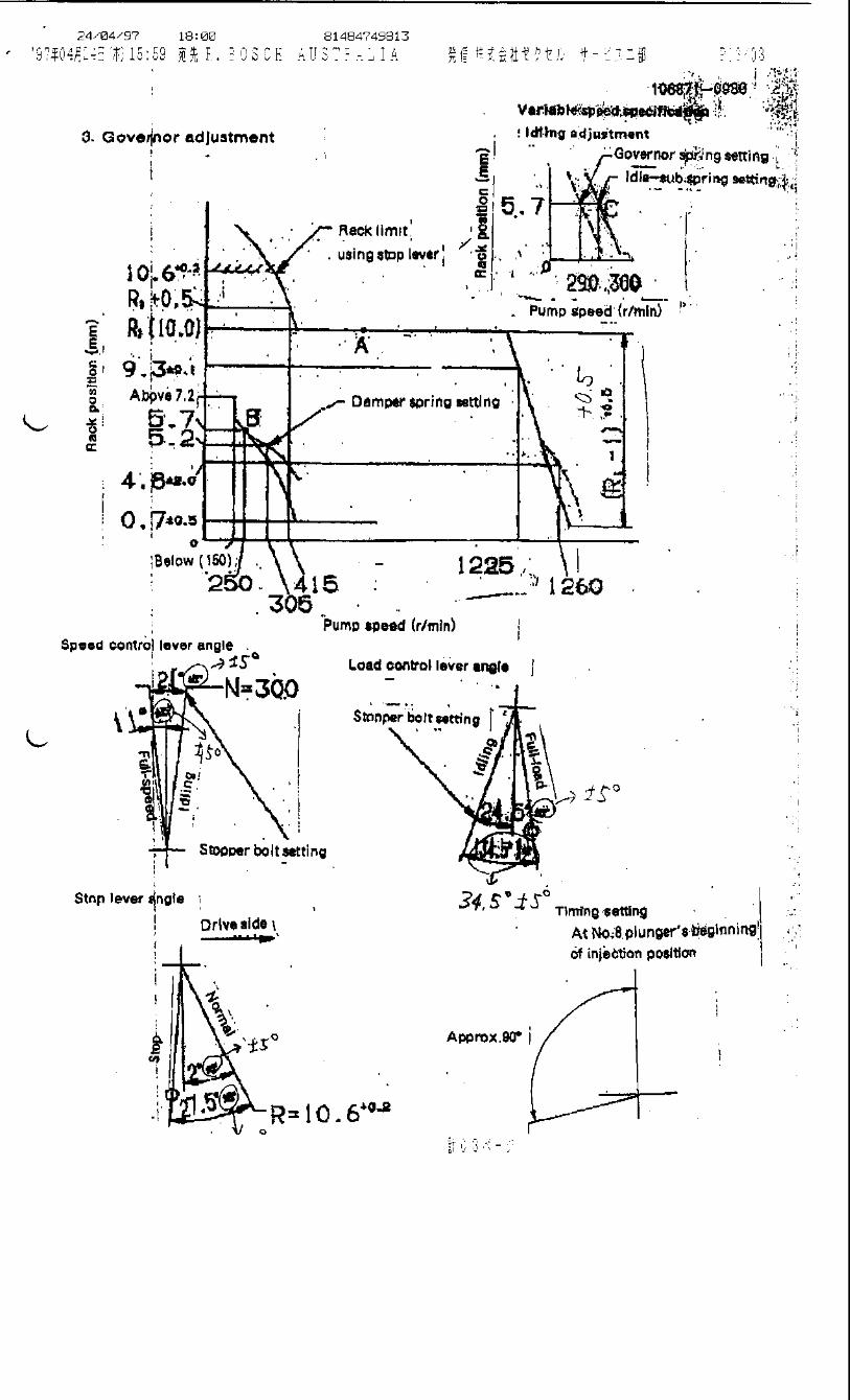

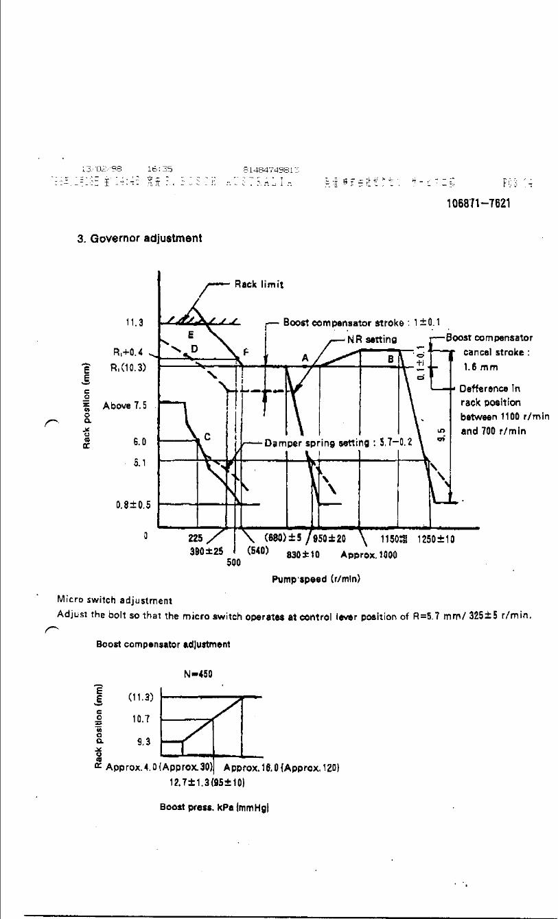
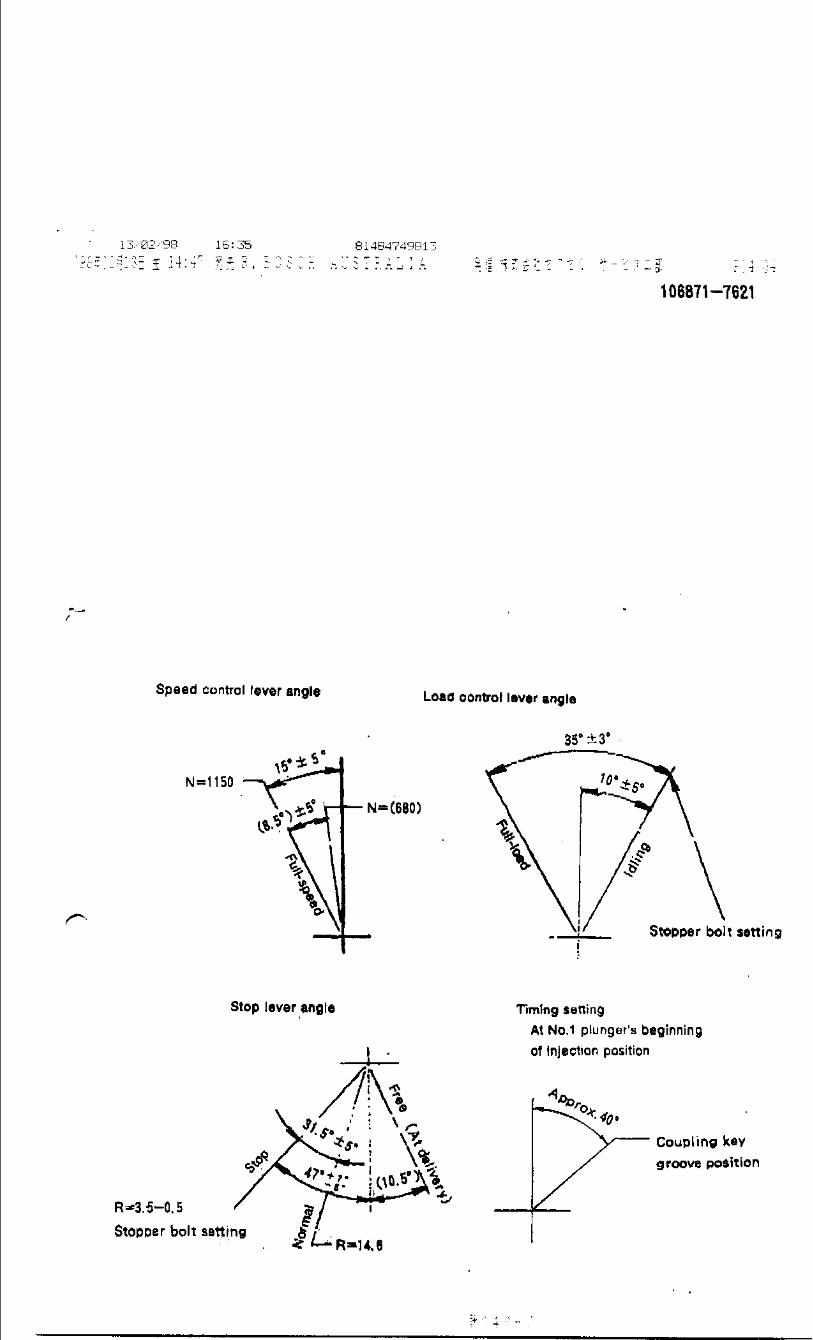
Oil temperature: 40+5 °C
BOSCH K.K.Sales Automotive Aftermarket Division
3-4-1 Kitano, Niiza-shi, Saitama-ken, 352-8572, JAPAN
Tel. 81-48-475-2521 Fax. 81-48-475-2520
Adjustingpoint
Rackposition
(mm)
Pumpspeed(r/min)
Injection quantity(cm3/1000 strokes)
Max. variationbetween
cylinders (%)Fixed Remarks
B 8.1 700 85.6 ± 1.5 ± 2 Lever Basic
C (7.9) 1250 (95.9) ± 2 ± 3 Lever
D Approx 5.4 225 8 ± 1.4 ± 13 Rack
E (10.3) 150 (102) - Lever
F - 150 Above 137 - Lever
Injection order:
Pump speed(r/min)
(Measure) (Measure) (1075) 1150 1250
Advanceangle (° )
Start
0 1 - 0.5 1 - 0.5 2.5 ± 0.3
Finish
5+1
4. Injection quantity
5. Timing advance specification
Company:
Assy No.: 106961-1564ENGINE MODEL: 12PC1
No. Governor: EP/RFD-D Timing device: EP/SPM
1. Test conditions
Date:
Pump rotation: clockwise (viewed from drive side)
Injection pump: PES12P105488-0430 105687-0200
kgf/cm2}
2. Injection timing
Pre-stroke: No.1 plunger 4 ± 0.03mm mm
Plungers are numbered from the ° ± 30').
CONFIDENTIAL
INJECTION PUMP CALIBRATION DATA
28 Jul 2004
115601-7317
106096-9241
Injection pipe: outer dia. 8 mm × inner dia. 3 mm length 600 mm
Nozzle opening pressure: 17.2 MPa {175 kgf/cm2}
Nozzle: 105780-0000 Nozzle holder: 105780-2080(Bosch type no. DN12SD12T) (Bosch type no. EF8511/9)
Nozzle & nozzle holder assy: 105780-8140 (Bosch type no. EF8511/9A)
Test oil: ISO4113 or SAE standard test oil {SAE J967d}
side (interval:
7
Transfer pump pressure: 157 kPa {1.6
Note: Adjust with rack position of
1 3 , 1 6 , 1 7 , 1 12 255°± 15' 300°± 15' 315°± 15'240°± 15'
1 4 , 1 9 , 1 8 , 1 5 , 1 2 , 1 11 , 1 10 ,15°± 15' 60°± 15' 75°± 15' 120°± 15' 135°± 15' 180°± 15' 195°± 15'
ISUZU
Governor side
1/3
Tappet clearance: Manually rotate the camshaft 2 to 3 times and confirm that it rotates smoothly.
Overflow valve opening pressure: 255 ± 34 kPa {2.6 ± 0.35 kgf/cm2} Drive sideOverflow valve opening pressure: 255 ± 34 kPa {2.6 ± 0.35 kgf/cm2}
Governor
Excessive fuel lever ; Normal position
Excessive fuel lever ; Excessive fuel position
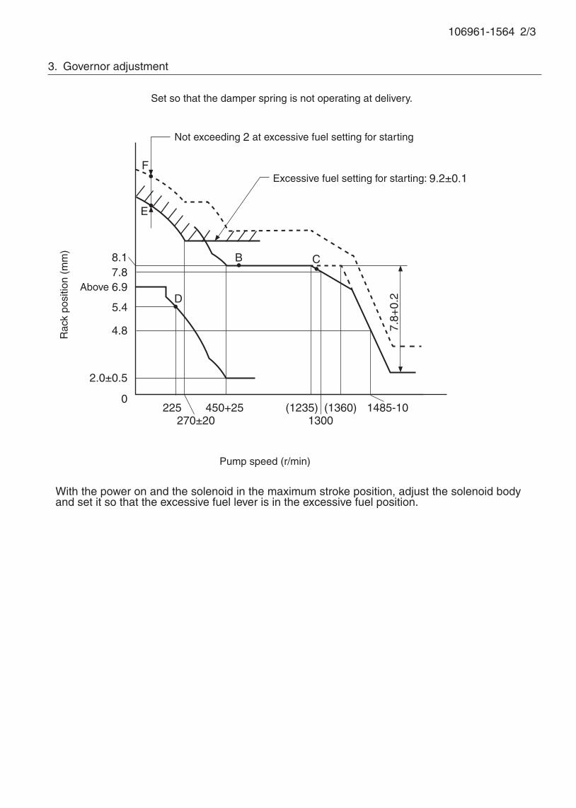
106961-1564 2/3
3. Governor adjustment
D
8.1
Above 6.9
5.4
2.0±0.5
0225
7.8+
0.2
Rac
k po
sitio
n (m
m)
Pump speed (r/min)
Excessive fuel setting for starting: 9.2±0.1
4.8
7.8
450+25 (1360)
C
F
E
270±20(1235)
13001485-10
Not exceeding 2 at excessive fuel setting for starting
Set so that the damper spring is not operating at delivery.
With the power on and the solenoid in the maximum stroke position, adjust the solenoid body and set it so that the excessive fuel lever is in the excessive fuel position.
B

106961-1564 3/3
Approx.5°
Stop lever angleExcessive fuel lever angle
(24°)
Load control lever angle
Full-load
At excessive fuel for starting
Speed-control lever angle
Full-speed
9° ±5°
Idling
Stopper bolt setting
33°±3°
10°±5°
60°±5° 73° ±5°
Normal Stop
Normal
Timing setting
At No. 1 plunger’s beginning of injection positionB.T.D.C.: 12°
Approx. 170°
Gear mark "Z"governor side
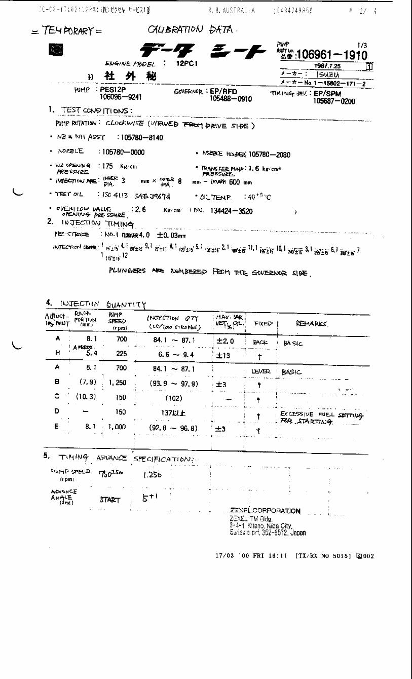

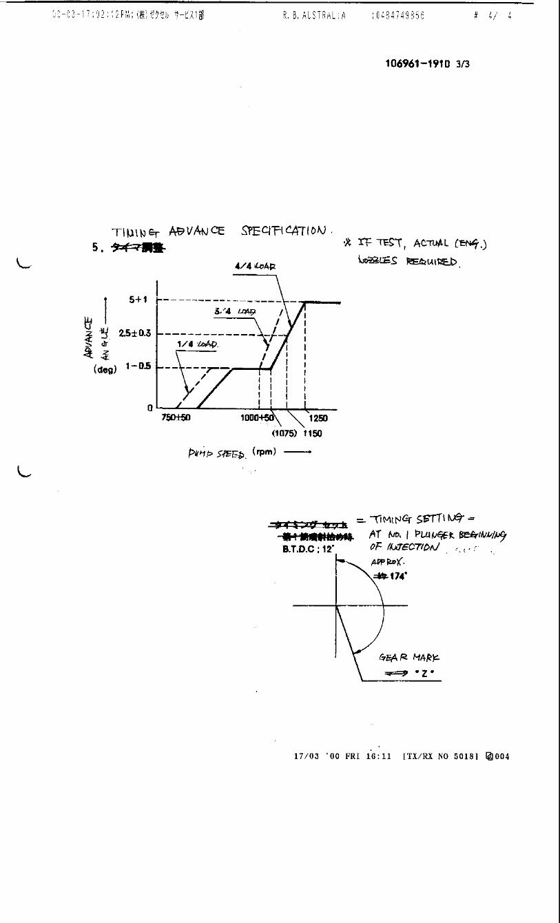
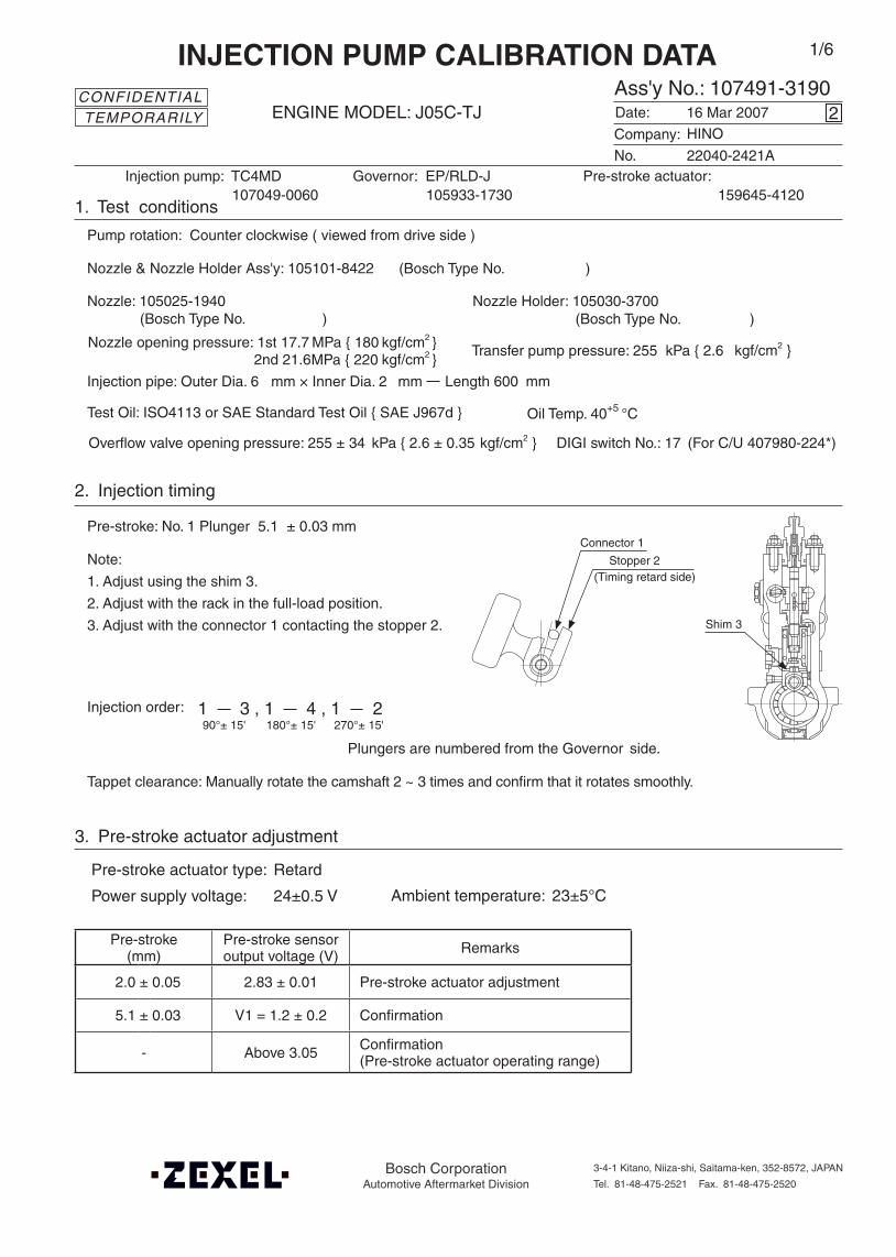
Pre-stroke(mm)
Pre-stroke sensoroutput voltage (V) Remarks
2.0 ± 0.05 2.83 ± 0.01 Pre-stroke actuator adjustment
5.1 ± 0.03 V1 = 1.2 ± 0.2 Confirmation
- Above 3.05 Confirmation(Pre-stroke actuator operating range)
Note:
1. Adjust using the shim 3.
2. Adjust with the rack in the full-load position.
3. Adjust with the connector 1 contacting the stopper 2.
Injection order:
2. Injection timing
Pre-stroke: No. 1 Plunger 5.1 ± 0.03 mm
Plungers are numbered from the Governor side.
Tappet clearance: Manually rotate the camshaft 2 ~ 3 times and confirm that it rotates smoothly.
Shim 3
DIGI switch No.: 17 (For C/U 407980-224*)
Oil Temp. 40+5 °C
Company:
Ass'y No.: 107491-3190ENGINE MODEL: J05C-TJ
No. Governor: EP/RLD-J
1. Test conditions
Date:
Pump rotation: Counter clockwise ( viewed from drive side )
Injection pump: TC4MD105933-1730
kgf/cm2 }
CONFIDENTIAL
INJECTION PUMP CALIBRATION DATA
16 Mar 2007
22040-2421A
107049-0060
Injection pipe: Outer Dia. 6 mm × Inner Dia. 2 mm Length 600 mm
Nozzle: 105025-1940 Nozzle Holder: 105030-3700(Bosch Type No. ) (Bosch Type No. )
Nozzle & Nozzle Holder Ass'y: 105101-8422 (Bosch Type No. )
Test Oil: ISO4113 or SAE Standard Test Oil { SAE J967d }
2
Transfer pump pressure: 255 kPa { 2.6
1/6
Pre-stroke actuator:159645-4120
3. Pre-stroke actuator adjustment
Pre-stroke actuator type: Retard
Power supply voltage: 24±0.5 V Ambient temperature: 23±5°C
(Timing retard side)
Connector 1
Stopper 2
1 3 , 1 4 , 1 290°± 15' 180°± 15' 270°± 15'
HINO
Overflow valve opening pressure: 255 ± 34 kPa { 2.6 ± 0.35 kgf/cm2 }
TEMPORARILY
Nozzle opening pressure: 1st 17.7 MPa { 180 kgf/cm2 } 2nd 21.6 kgf/cm2 }MPa { 220
Bosch CorporationAutomotive Aftermarket Division
3-4-1 Kitano, Niiza-shi, Saitama-ken, 352-8572, JAPAN
Tel. 81-48-475-2521 Fax. 81-48-475-2520
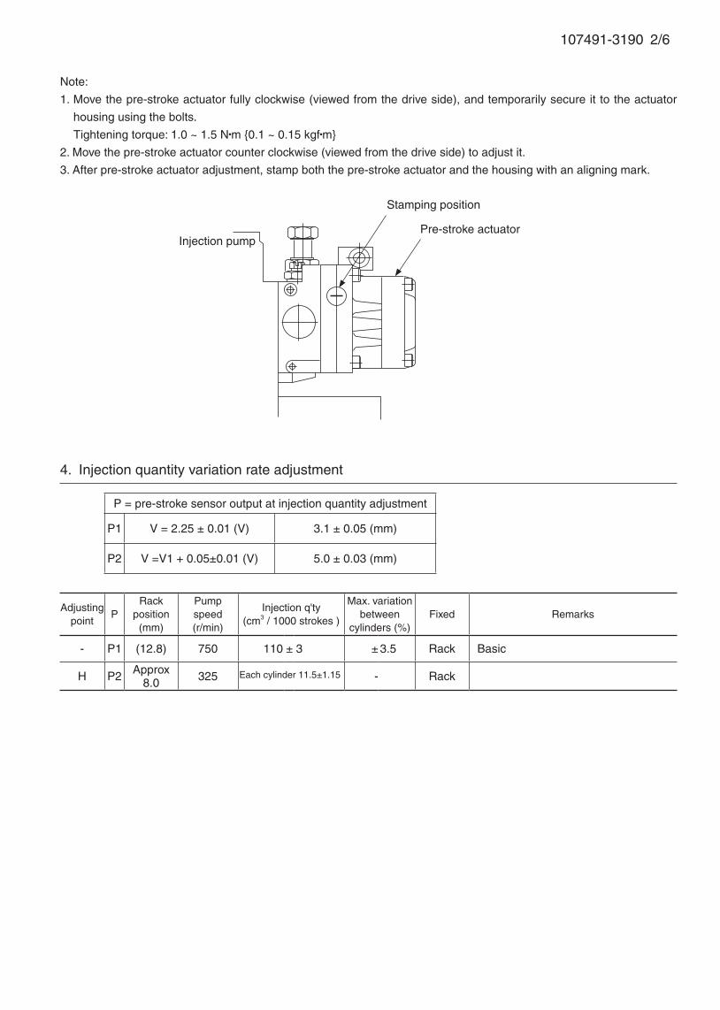
107491-3190 2/6
Note:
1. Move the pre-stroke actuator fully clockwise (viewed from the drive side), and temporarily secure it to the actuator
housing using the bolts.
Tightening torque: 1.0 ~ 1.5 N•m {0.1 ~ 0.15 kgf•m}
2. Move the pre-stroke actuator counter clockwise (viewed from the drive side) to adjust it.
3. After pre-stroke actuator adjustment, stamp both the pre-stroke actuator and the housing with an aligning mark.
Injection pump
Stamping position
Pre-stroke actuator
Adjustingpoint
PRack
position(mm)
Pumpspeed(r/min)
Injection q'ty(cm3 / 1000 strokes )
Max. variationbetween
cylinders (%)Fixed Remarks
- P1 (12.8) 750 110 ± 3 ± 3.5 Rack Basic
H P2 Approx8.0 325 - Rack
4. Injection quantity variation rate adjustment
P = pre-stroke sensor output at injection quantity adjustment
P1 V = 2.25 ± 0.01 (V) 3.1 ± 0.05 (mm)
P2 V =V1 + 0.05±0.01 (V) 5.0 ± 0.03 (mm)
Each cylinder 11.5±1.15

107491-3190 3/6
5. Governor adjustment
0230
325375 800
Rac
k po
sitio
n (m
m)
Pump speed (r/min)
10.0
9.7+0.2-0.3
R1-0.25
Approx R1+0.4
0Below 275 (500) (1200)
A
B
Rac
k po
sitio
n (m
m)
Pump speed (r/min)
Torque cam no. ‘AH27’
R1+2.15
R1(12.8)
650
(700)
(800) (1300)
1500
450
4.5±0.6
8.0Approx 8.0
Full load adjustment
Idling adjustment
Boost compensator stroke: 1.15±0.1
12.3±0.1R1-0.95(R2)
11.4±1.0
1530
6.8±0.1
R1-0.95(R2)
R2-1.15
0
23.3±1.3 {175±10}
Approx 37.3 {Approx 280}
N = 400
Rac
k po
sitio
n (m
m)
Boost pressure kPa {mmHg}
Boost compensator adjustment
I
H J
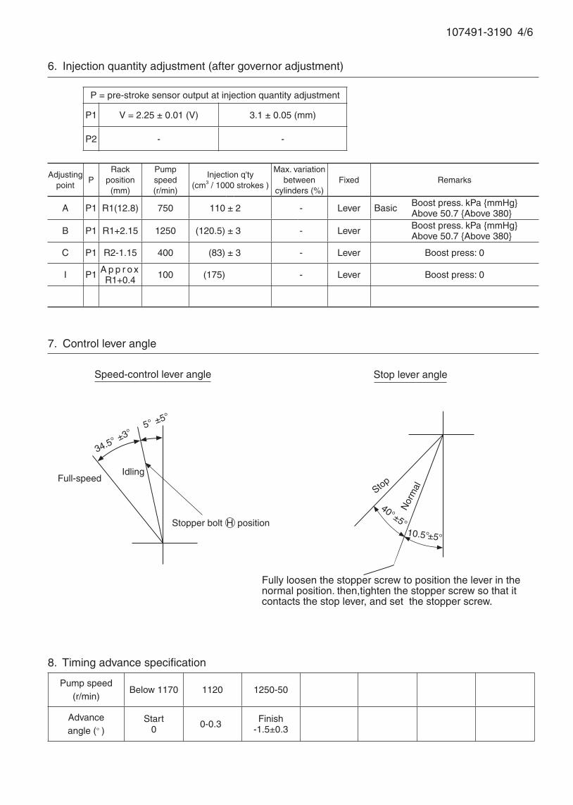
7. Control lever angle
Pump speed(r/min)
Below 1170 1120 1250-50
Advanceangle (° )
Start0 0 -0.3 Finish
-1.5±0.3
8. Timing advance specification
107491-3190 4/6
Adjustingpoint
PRack
position(mm)
Pumpspeed(r/min)
Injection q'ty(cm3 / 1000 strokes )
Max. variationbetween
cylinders (%)Fixed Remarks
A P1 R1(12.8) 750 110 ± 2 - Lever Boost press. kPa {mmHg} Above 50.7 {Above 380}
B P1 R1+2.15 1250 (120.5) ± 3 - Lever Boost press. kPa {mmHg} Above 50.7 {Above 380}
C P1 R2-1.15 400 (83) ± 3 - Lever Boost press: 0
I P1 A p p r o x R1+0.4 100 (175) - Lever Boost press: 0
6. Injection quantity adjustment (after governor adjustment)
P = pre-stroke sensor output at injection quantity adjustment
P1 V = 2.25 ± 0.01 (V) 3.1 ± 0.05 (mm)
P2 - -
34.5° ±3°
Speed-control lever angle
Idling
Stop lever angle
Full-speed
5° ±5°
Fully loosen the stopper screw to position the lever in the normal position. then,tighten the stopper screw so that it contacts the stop lever, and set the stopper screw.
10.5°±5°
40°±5°
Nor
malStop
Basic
Stopper bolt H position

107491-3190 5/6
1. Turn the pre-stroke actuator OFF.
2. Position the camshaft in the No.1 plunger's beginning of injection position.
3. Confirm that the injection pump pointer's aligning mark and the flywheel's aligning mark are aligned.
4. If not aligned, remove the incorrect flywheel aligning mark and remark it.
5. Confirm that the center of the flywheel's threaded hole is as specified.
9. Injection timing setting
At No. 1 plunger’s beginning of injection position(Pre-stroke: 5.1±0.03 mm)
Injection timing aligning mark
Pointer
Flywheel
(Actual shapes and positions may differfrom the illustration.)
Coupling key groove positionApprox.30°

107491-3190 6/6
10. Rack sensor adjustment
Amp-equipped rack sensor adjustment (154610-5*20)• Threaded type rack sensor (without rack limit; for P type, TICS)
(1) Screw in bobbin 1 until it contacts the joint 2.
(2) Fix the pump lever at full and screw in the bobbin 1 to adjust the depth so that the amp’s output
voltage V = VR at Np = No and R = Ro. Then, fix the rack sensor using the nut 6.
(3) Move the pump lever 2 or 3 times, reset at full and confirm that the amp’s output voltage V = VR.
(4) Attach the caution plate to the top of the joint 2 and apply red paint to the joint 2 - nut 6 join, and the
pump end face - joint 2 join.
Note:
(1) When adjusting the bobbin 1 and joint 2, the fully tightened position of the bobbin is 9 threads (ie, 9
turns) from where it first engages the joint.
(2) With the welded rack block type, refer to the table below for the R = Ro range (the range varies with
the joint).
Rack sensor power supply 5±0.01V
Speed No 1250 r/min
Rack position Ro R1(12.8) + 2.15 mm
Output voltage VR 3.00±0.01V
Threaded rack block type Welded rack block type
6 1 2
5 4 3
Apply red paint
Pump end face
6 1 2 Apply red paint
Pump end face
4 3
Rack sensor adjusting position
Ro
No Np
Rac
k po
sitio
n Output voltage
VR
Ro
Adjustment Np = No
Joint part no. Ro
154614-2500 10.2 ~ 13.7
154614-4800 5.2 ~ 8.7
154614-8300 15.2 ~ 18.7
154614-8400 20.2 ~ 23.7
154614-8700 7.7 ~ 11.2
154614-8800 12.7 ~ 16.2
154614-8900 17.7 ~ 21.2
Pre-stroke(mm)
Pre-stroke sensoroutput voltage (V) Remarks
2.0 ± 0.05 2.83 ± 0.01 Pre-stroke actuator adjustment
5.1 ± 0.03 V1 = 1.2 ± 0.2 Confirmation
- Above 3.05 Confirmation(Pre-stroke actuator operating range)
Note:
1. Adjust using the shim 3.
2. Adjust with the rack in the full-load position.
3. Adjust with the connector 1 contacting the stopper 2.
Injection order:
2. Injection timing
Pre-stroke: No. 1 Plunger 5.1 ± 0.03 mm
Plungers are numbered from the Governor side.
Tappet clearance: Manually rotate the camshaft 2 ~ 3 times and confirm that it rotates smoothly.
Shim 3
DIGI switch No.: 17 (For C/U 407980-224*)
Oil Temp. 40+5 °C
Bosch Automotive Systems Corporation
Service Department
3-4-1 Kitano, Niiza-shi, Saitama-ken, 352-8572 Japan
Tel. (048)470-1559, Fax. (048)474-9856
Company:
Ass'y No.: 107491-3191ENGINE MODEL: J05C-TJ
No. Governor: EP/RLD-J
1. Test conditions
Date:
Pump rotation: Counter clockwise ( viewed from drive side )
Injection pump: TC4MD105933-1730
kgf/cm2 }
CONFIDENTIAL
INJECTION PUMP CALIBRATION DATA
29 Nov 2002
22040-2421A
107049-0061
Injection pipe: Outer Dia. 8 mm × Inner Dia. 3 mm Length 600 mm
Nozzle opening pressure: 20.7 MPa { 211 kgf/cm2 }
Nozzle: 105780-0120 Nozzle Holder: 105780-2190(Bosch Type No. 1 688 901 990) (Bosch Type No. )
Nozzle & Nozzle Holder Ass'y: 105780-8250 (Bosch Type No. 1 688 901 101)
Test Oil: ISO4113 or SAE Standard Test Oil { SAE J967d }
4
Transfer pump pressure: 255 kPa { 2.6
1/6
Pre-stroke actuator:159645-4120
3. Pre-stroke actuator adjustment
Pre-stroke actuator type: Retard
Power supply voltage: 24±0.5 V Ambient temperature: 23±5°C
(Timing retard side)
Connector 1
Stopper 2
1 3 , 1 4 , 1 290°± 15' 180°± 15' 270°± 15'
HINO
Overflow valve opening pressure: 255 ± 34 kPa { 2.6 ± 0.35 kgf/cm2 }

107491-3191 2/6
Note:
1. Move the pre-stroke actuator fully clockwise (viewed from the drive side), and temporarily secure it to the actuator
housing using the bolts.
Tightening torque: 1.0 ~ 1.5 N•m {0.1 ~ 0.15 kgf•m}
2. Move the pre-stroke actuator counter clockwise (viewed from the drive side) to adjust it.
3. After pre-stroke actuator adjustment, stamp both the pre-stroke actuator and the housing with an aligning mark.
Injection pump
Stamping position
Pre-stroke actuator
Adjustingpoint
PRack
position(mm)
Pumpspeed(r/min)
Injection q'ty(cm3 / 1000 strokes )
Max. variationbetween
cylinders (%)Fixed Remarks
- P1 13.1 750 123.5 ± 3 ± 3.5 Rack Basic
Z P2 8.0±0.5 505 - Rack Adjust injection q'ty at N = 505.Adjust governor as per gov. adj. spec.
4. Injection quantity variation rate adjustment
P = pre-stroke sensor output at injection quantity adjustment
P1 V = 2.25 ± 0.01 (V) 3.1 ± 0.05 (mm)
P2 V =V1 + 0.05±0.01 (V) 5.0 ± 0.03 (mm)
Each cylinder 11.5±1.15
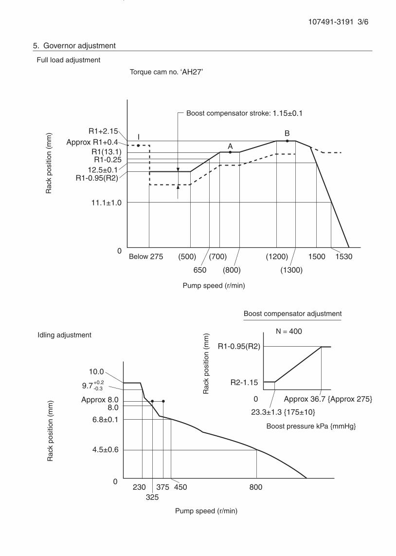
107491-3191 3/6
If not indicated, the rack position allowance is ± 0.05 mm.
5. Governor adjustment
0230
325375 800
Rac
k po
sitio
n (m
m)
Pump speed (r/min)
10.0
9.7+0.2-0.3
R1-0.25
Approx R1+0.4
0Below 275 (500) (1200)
A
B
Rac
k po
sitio
n (m
m)
Pump speed (r/min)
Torque cam no. ‘AH27’
R1+2.15
R1(13.1)
650
(700)
(800) (1300)
1500
450
4.5±0.6
8.0Approx 8.0
Full load adjustment
Idling adjustment
Boost compensator stroke: 1.15±0.1
12.5±0.1R1-0.95(R2)
11.1±1.0
1530
6.8±0.1
R1-0.95(R2)
R2-1.15
0
23.3±1.3 {175±10}
Approx 36.7 {Approx 275}
N = 400
Rac
k po
sitio
n (m
m)
Boost pressure kPa {mmHg}
Boost compensator adjustment
I
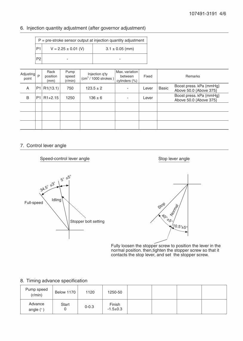
7. Control lever angle
Pump speed(r/min)
Below 1170 1120 1250-50
Advanceangle (° )
Start0 0 -0.3 Finish
-1.5±0.3
8. Timing advance specification
107491-3191 4/6
Adjustingpoint
PRack
position(mm)
Pumpspeed(r/min)
Injection q'ty(cm3 / 1000 strokes )
Max. variationbetween
cylinders (%)Fixed Remarks
A P1 R1(13.1) 750 123.5 ± 2 - Lever Boost press. kPa {mmHg} Above 50.0 {Above 375}
B P1 R1+2.15 1250 136 ± 6 - Lever Boost press. kPa {mmHg} Above 50.0 {Above 375}
6. Injection quantity adjustment (after governor adjustment)
P = pre-stroke sensor output at injection quantity adjustment
P1 V = 2.25 ± 0.01 (V) 3.1 ± 0.05 (mm)
P2 - -
34.5° ±3°
Speed-control lever angle
Idling
Stopper bolt setting
Stop lever angle
Full-speed
5° ±5°
Fully loosen the stopper screw to position the lever in the normal position. then,tighten the stopper screw so that it contacts the stop lever, and set the stopper screw.
10.5°±5°
40°±5°
Nor
malStop
Basic
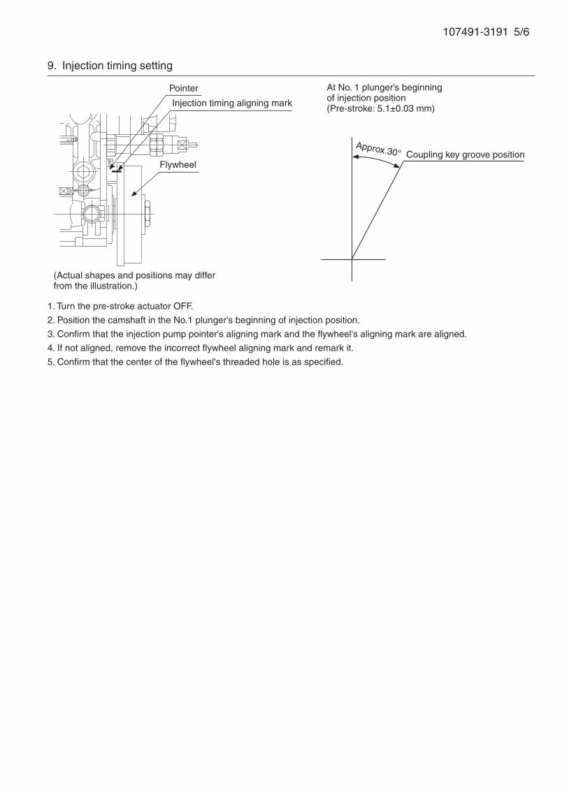
107491-3191 5/6
1. Turn the pre-stroke actuator OFF.
2. Position the camshaft in the No.1 plunger's beginning of injection position.
3. Confirm that the injection pump pointer's aligning mark and the flywheel's aligning mark are aligned.
4. If not aligned, remove the incorrect flywheel aligning mark and remark it.
5. Confirm that the center of the flywheel's threaded hole is as specified.
9. Injection timing setting
At No. 1 plunger’s beginning of injection position(Pre-stroke: 5.1±0.03 mm)
Injection timing aligning mark
Pointer
Flywheel
(Actual shapes and positions may differfrom the illustration.)
Coupling key groove positionApprox.30°
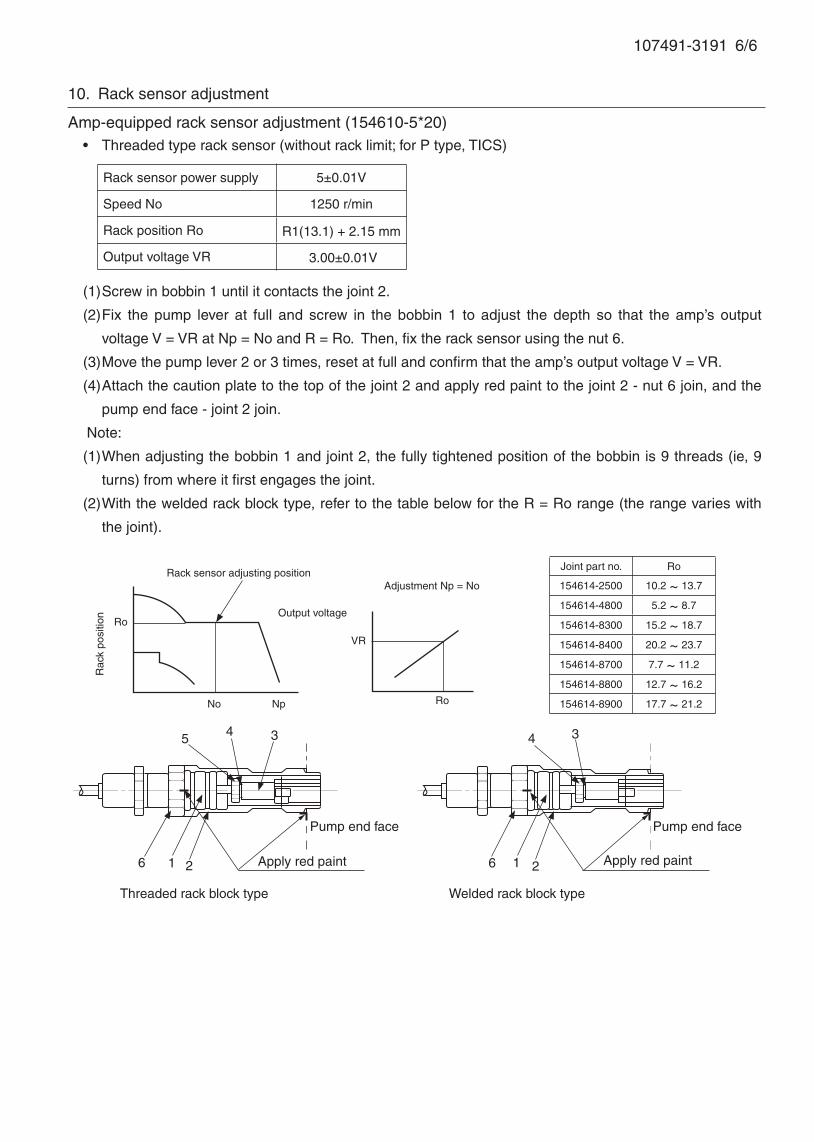
107491-3191 6/6
10. Rack sensor adjustment
Amp-equipped rack sensor adjustment (154610-5*20)• Threaded type rack sensor (without rack limit; for P type, TICS)
(1) Screw in bobbin 1 until it contacts the joint 2.
(2) Fix the pump lever at full and screw in the bobbin 1 to adjust the depth so that the amp’s output
voltage V = VR at Np = No and R = Ro. Then, fix the rack sensor using the nut 6.
(3) Move the pump lever 2 or 3 times, reset at full and confirm that the amp’s output voltage V = VR.
(4) Attach the caution plate to the top of the joint 2 and apply red paint to the joint 2 - nut 6 join, and the
pump end face - joint 2 join.
Note:
(1) When adjusting the bobbin 1 and joint 2, the fully tightened position of the bobbin is 9 threads (ie, 9
turns) from where it first engages the joint.
(2) With the welded rack block type, refer to the table below for the R = Ro range (the range varies with
the joint).
Rack sensor power supply 5±0.01V
Speed No 1250 r/min
Rack position Ro R1(13.1) + 2.15 mm
Output voltage VR 3.00±0.01V
Threaded rack block type Welded rack block type
6 1 2
5 4 3
Apply red paint
Pump end face
6 1 2 Apply red paint
Pump end face
4 3
Rack sensor adjusting position
Ro
No Np
Rac
k po
sitio
n Output voltage
VR
Ro
Adjustment Np = No
Joint part no. Ro
154614-2500 10.2 ~ 13.7
154614-4800 5.2 ~ 8.7
154614-8300 15.2 ~ 18.7
154614-8400 20.2 ~ 23.7
154614-8700 7.7 ~ 11.2
154614-8800 12.7 ~ 16.2
154614-8900 17.7 ~ 21.2
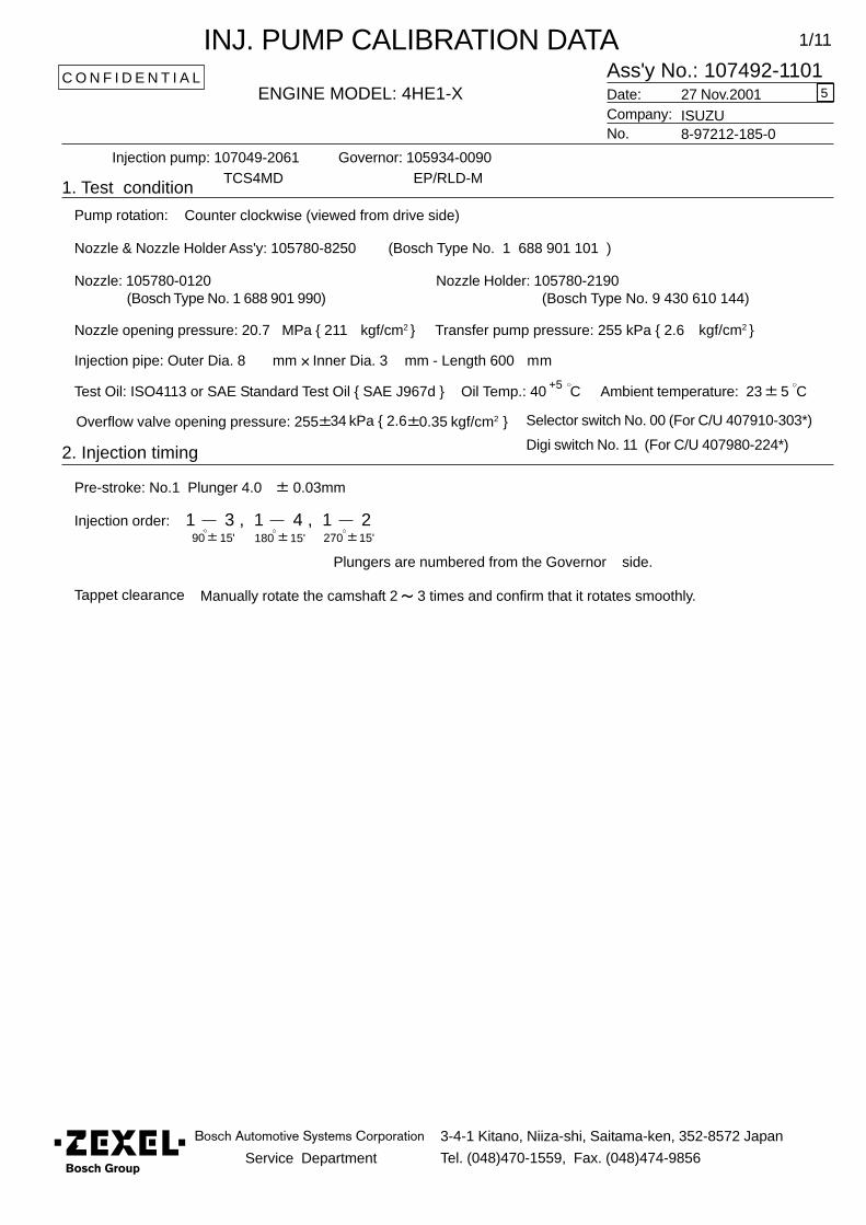
Service Department
3-4-1 Kitano, Niiza-shi, Saitama-ken, 352-8572 Japan
Tel. (048)470-1559, Fax. (048)474-9856
1/11
Ass'y No.: 107492-1101ENGINE MODEL: 4HE1-X
No.
Governor: 105934-0090
1. Test condition
Date:
Pump rotation:
Injection pump: 107049-2061 EP/RLD-M
kgf/cm2 }
2. Injection timing
Pre-stroke: No.1 Plunger 4.0 0.03mm
Injection order:
Plungers are numbered from the Governor
Tappet clearance Manually rotate the camshaft 2 3 times and confirm that it rotates smoothly.
C O N F I D E N T I A L
INJ. PUMP CALIBRATION DATA
Company:27 Nov.2001
ISUZU8-97212-185-0
TCS4MD
Injection pipe: Outer Dia. 8 mm Inner Dia. 3 mm - Length 600 mm
Nozzle opening pressure: 20.7 MPa { 211 kgf/cm2 } Transfer pump pressure: 255 kPa { 2.6
Nozzle: 105780-0120 Nozzle Holder: 105780-2190(Bosch Type No. 1 688 901 990) (Bosch Type No. 9 430 610 144)
Nozzle & Nozzle Holder Ass'y: 105780-8250 (Bosch Type No. 1 688 901 101 )
Test Oil: ISO4113 or SAE Standard Test Oil { SAE J967d } Oil Temp.: 40 C+5
side.
Counter clockwise (viewed from drive side)
Ambient temperature: 23 5 C
1 3 , 1 4 , 1 290 15' 180 15' 270 15'
5
Overflow valve opening pressure: 255 34 kPa { 2.6 0.35 kgf/cm2 } Selector switch No. 00 (For C/U 407910-303*)
Digi switch No. 11 (For C/U 407980-224*)

107492-1101 2/11
3. Injection timing adjustment
(Refer to the MITICS Repair and Maintenance Service Manual for adjustment details.)
3-1 Adjustment Preparation
(1) Install setscrew ③ (P/N 157927-2820), screw ④ (P/N 157927-3321) and solenoid switch
⑤ into housing ① .
(2) -1. Screw in setscrew ③ until the counterweight contacts the housing's pressfitted
stopper pin.
-2. Tighten screw ④ until clearance between screw ④ and counterweight ② is 1~2
mm.
-3. Tighten solenoid switch ⑤ until clearance between solenoid switch and
counterweight ② 's pin is 1~ 2 mm, then tighten locknut ⑥ .
(3) Install starting advance mechanism's cover.
(4) Position control rack in full position.
(5) Set power supply voltage to manual controller at 12V.
3-2 Pre-stroke adjustment
Adjust No 1 cylinder's start of static injection using the shim ① .
3-3 Individual cylinder's injection order adjustment
Adjust difference between each cylinder's injection angle based on that of the No. 1
cylinder using the shim ① .
1. Setscrew installation 2. Pre-stroke adjustment
3. Individual cylinder's injection
order adjustment
1
2
4
563
107492-1101 3/11
3-4 Measuring pre-stroke output voltage
(1) Install measuring device (P/N 105782-6420).
(2) Remove setscrew ③ (P/N 157927-2820) and install air bleeder bolt.
(3) Screw in screw ④ (P/N 157927-3321) and measure the No 1 cylinder's output voltage
for pre-stroke lift values in the table below.
Advice
If measuring device (P/N 105782-6420) is removed, the output voltage (a1, a2) should be
remeasured.
3-5 Minimum advance angle adjustment stopper adjustment
(1) Remove screw ④ (P/N 157927-3321) and install minimum advance angle adjustment
stopper.
(2) Screw in minimum advance angle adjustment stopper until No 1 cylinder's pre-stroke
is 3.67 ~ 3.73. Then, tighten locknut to specified torque.
(3) Measure the output voltage (c) at this time.
3-6 Solenoid switch adjustment
(1) Apply 24 V voltage to solenoid switch ⑤ .
(2) Loosen solenoid switch ⑤ until No 1 cylinder's pre-stroke is 1.90 ~ 2.03 mm, then
tighten locknut to specified torque.
(3) Confirm solenoid switch operates at 14.5 -0.1 V.
Adjusting pointConfirmation point
Pre-stroke (mm) Output voltage (actual) Remarks
a3.36 a1 + tolerance
3.10 a2 -tolerance
b2.96 b1 + tolerance
2.76 b2 -tolerance
(calculate from each specification)
107492-1101 4/11
Rac
k po
sitio
n (
mm
)
Idling adjustment
Pump speed (r/min)
Rac
k po
sitio
n (
mm
)
Boost compensator stroke: 1.25 ±0.1
Torque cam No. “ AF60”
Pump speed (r/min)
Confirm rack sensor Vist = 2.55±0.28
at supply voltage 5±0.01V , N =1000 r/min , R = R1 (15.0).
4. Governor adjustment
4-1. Governor adjustment
Full load adjustment
Advice
Loosen timing cam and lock screw.
Fully tighten the adjusting nut.
R1+0.9
Approx.R1+0.3R1(15.0)
R2 [R1-2.15]
10.7± 1.0
0250-40 (650) 1000 (1150)
(1600)
1690
1810
13.9± 0.1
A
B
D
C
I
10.510.0± 0.1
Approx.8.9
7.8
6.6± 0.1
3.9± 0.3
0 880500
475
400
400
240
H J

107492-1101 5/11
4-2 Boost compensator adjustment
(1) Select a push rod so C = 37.5±0.5 at full boost pressure. (C is the distance from the
end face of the housing to top of the lever.)
(2) Adjust the boost compensator stroke using screw A.
(0 boost pressure position adjustment)
Adjust the beginning of boost compensator operation by adjusting the notch adjusting
nut B.
Boost pressure inlet
A Boost compensator
stroke adjusting screw
Boost compensator spring
B Notch adjusting nut
Top of lever
Boost press. kPa{mmHg}
Rac
k po
sitio
n (
mm
) N = 500 r/min
R2 [R1-2.15]
R2-1.25
Approx. 28.7 {Approx. 215}
12.0± 1.3 {90± 10}
PushrodC
0

107492-1101 6/11
4-3 Timing cam adjustment (Timing cam No:A07)
(1) Hold speed control lever against full speed stopper bolt.
(2) Supply boost pressure of at least 42.0 kPa {at least 315 mmHg}.
(3) Operate pump at the timing cam adjusting point
(point a in table below: Np = 900 r/min).
(4) Perform timing cam adjustment so output voltage is within range of a1 ~ a2 actually
measured for pre-stroke output voltage during injection timing adjustment in 3-4.
(5) Operate the pump at the timing cam confirmation point
(point b in table below: Np = 1,200 r/min).
(6) Confirm that the pre-stroke output voltage is within the range b1~ b2.
Solenoid starting advance angle
b (confirmation point)
a (adjusting point)
Minimum advance angle adjustment
stopper
Pre-stroke(Pre-stroke output voltage)
Pump speed (r/min)
Pre-stroke at stopper contact
Adjusting point Pre-stroke (mm) Output voltage (actual) Remarks
a3.36 a1 + tolerance
3.10 a2 -tolerance
Confirmation point Pre-stroke (mm) Output voltage (actual) Remarks
b2.96 b1 + tolerance
2.76 b2 -tolerance
2.76 (b2)
2.96 (b1)
3.10 (a2)
3.36 (a1)
3.7± 0.03 (c)
4.0±0.03(500) 900 1,200
2.0 + 0.03- 0.10
0
Adjustingpoint
Rackposition( mm )
Pumpspeed
( r/min )
Injection q'ty( cm3/100 strokes )
Max.variationbetweencylinders
FixedPre-stroke
at adjustmentRemarks
- 15.0 1,000 109.5 ± 1.6 ±4 Rack a1~a2(v)
Z 8.9±0.5 510 22 ± 1.5 ± 14 Rack c(v)
A R1(15.0) 1,000 109.5 ± 1 - Lever a1~a2(v)
B R1+0.9 1,200 (112.5) ± 2 - Lever b1~b2(v)
IApprox.
R1+0.3150 (180) - Lever c(v)
D* 15.3±0.1 1,200 (106) - Lever b1~b2(v)
107492-1101 7/11
5. Injection quantity
Cylinder variation
adjustment standardBasic
BasicBoost press. kPa{mmHg}Above 42.0{Above 315}
Cylinder variation
adjustment standard
Boost press. 0
Boost press. kPa{mmHg}Above 42.0 {Above 315 }Negative press. kPa{mmHg} 53.3 kPa{ 400 mmHg}
D*: Aneroid compensator actuator adjustment point
Boost press. kPa{mmHg}Above 42.0{Above 315}

107492-1101 8/11
6. FICD Adjustment
(1) Stop the injection pump.
(2) Hold speed control lever against idling stopper bolt.
(3) Adjust clearance between FICD actuator lever and speed control lever to approx. 1+1mm.
(4) Loosen nut ③ and fully tighten FICD set bolt ② .
(5) Apply 53.3 kPa { 400 mmHg} negative pressure to the actuator ① and set the pump
speed at 450 r/min.
(6) Gradually loosen set bolt ② then fix bolt using nut when the rack position is 8.7±0.1 mm.
(7) Apply above negative pressure several times and confirm FICD actuator is operating
properly and clearance between FICD actuator lever and speed control lever.
Tightening torque
5 ~ 7 N.m {0.5 ~ 0.7 kgf.m}
FICD actuator lever
Speed control lever
②
1+1 mm
①
③

107492-1101 9/11
7. Aneroid compensator actuator adjustment ( injection quantity decrease )
Note:
Set this actuator after adjusting the full rack position.
(1) Stop injection pump.
(2) Adjust wire nut so full load set lever contacts full load set bolt and aneroid compensator
actuator wire is not loose. Then, fix the nut.
(3) Apply 53.3 kPa { 400 mmHg} negative pressure to aneroid compensator, set pump
speed at 1,200 r/min.
(4) Apply at least 42.0 kPa { 315 mmHg} boost pressure to the boost compensator.
(5) After operating full load set lever, adjust aneroid compensator set bolt so control rack
position is 15.3±0.1 mm and fuel injection quantity is as specified. Then, fix the set bolt.
Stroke
Injection quantity decrease
adjustment point
Full load set lever
Full load set bolt
D
Rac
k po
sitio
n (m
m)
Pump speed (r/min)
B
A
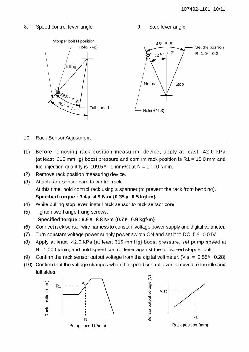
107492-1101 10/11
8. Speed control lever angle 9. Stop lever angle
Hole(R42)Stopper bolt H position
Idling
Full-speedHole(R41.3)
Set the position
R=1.5± 0.2
StopNormal
45°±5°
22.5°±5°
30°±5°
29.5°±3°
10. Rack Sensor Adjustment
(1) Before removing rack position measuring device, apply at least 42.0 kPa
{at least 315 mmHg} boost pressure and confirm rack position is R1 = 15.0 mm and
fuel injection quantity is 109.5± 1 mm3/st at N = 1,000 r/min.
(2) Remove rack position measuring device.
(3) Attach rack sensor core to control rack.
At this time, hold control rack using a spanner (to prevent the rack from bending).
Specified torque : 3.4~~~~~ 4.9 N.m {0.35~~~~~ 0.5 kgf.m}
(4) While pulling stop lever, install rack sensor to rack sensor core.
(5) Tighten two flange fixing screws.
Specified torque : 6.9~~~~~ 8.8 N.m {0.7~~~~~ 0.9 kgf.m}
(6) Connect rack sensor wire harness to constant voltage power supply and digital voltmeter.
(7) Turn constant voltage power supply power switch ON and set it to DC 5± 0.01V.
(8) Apply at least 42.0 kPa {at least 315 mmHg} boost pressure, set pump speed at
N= 1,000 r/min, and hold speed control lever against the full speed stopper bolt.
(9) Confirm the rack sensor output voltage from the digital voltmeter. (Vist = 2.55±0.28)
(10) Confirm that the voltage changes when the speed control lever is moved to the idle and
full sides.
Rac
k po
sitio
n (m
m)
R1
N
Pump speed (r/min)
Sen
sor
outp
ut v
olta
ge (
V)
Vist
R1
Rack position (mm)
A
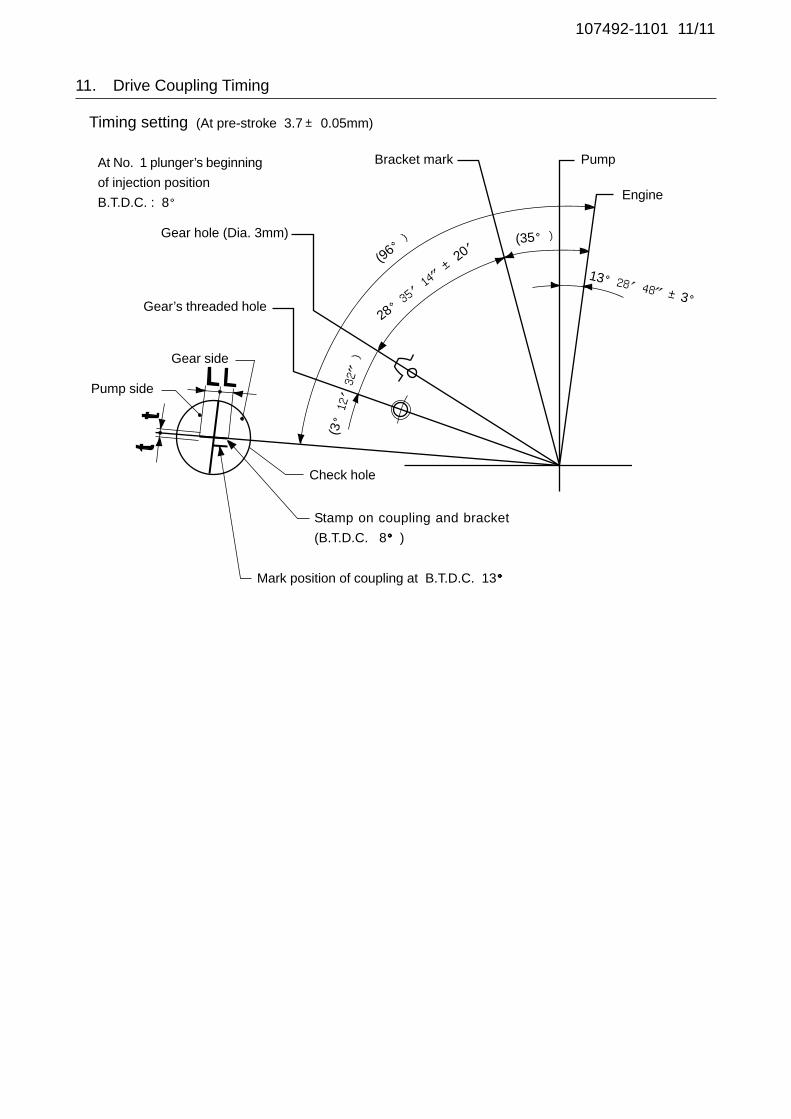
107492-1101 11/11
Timing setting
At No. 1 plunger’s beginning
of injection position
B.T.D.C. : 8°
(At pre-stroke 3.7± 0.05mm)
Pump
Engine
Bracket mark
Gear hole (Dia. 3mm)
Gear’s threaded hole
Gear side
Pump side
Stamp on coupling and bracket
(B.T.D.C. 8°°°°°)
Mark position of coupling at B.T.D.C. 13°°°°°
Check hole
28°35′14″±
20′
13°28′48″±3°
(35°)
(96°)
(3°12′32″)
11. Drive Coupling Timing
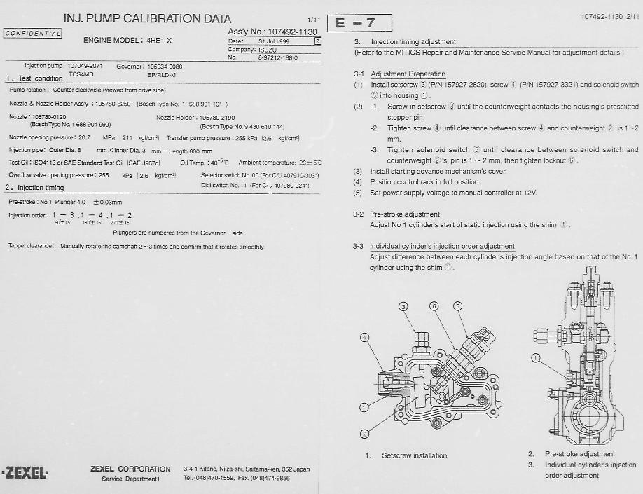
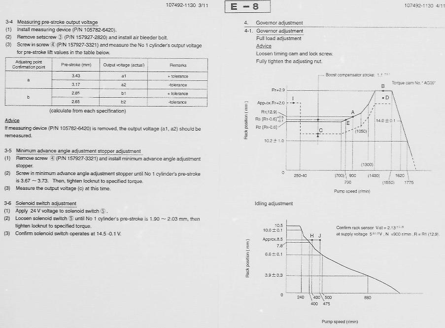

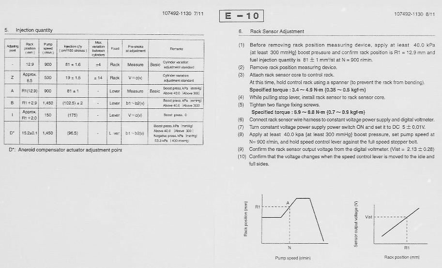
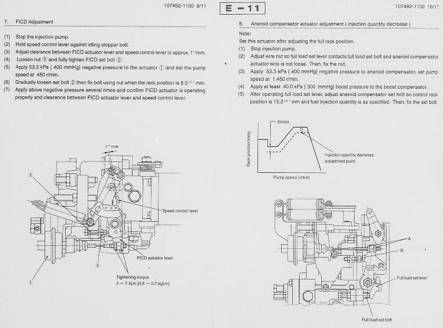
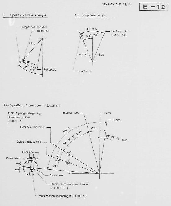
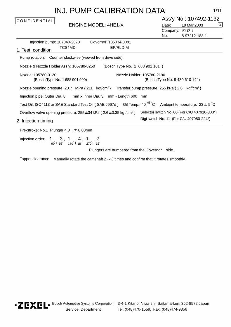
Service Department
3-4-1 Kitano, Niiza-shi, Saitama-ken, 352-8572 Japan
Tel. (048)470-1559, Fax. (048)474-9856
1/11
Ass'y No.: 107492-1132ENGINE MODEL: 4HE1-X
No.
Governor: 105934-0081
1. Test condition
Date:
Pump rotation:
Injection pump: 107049-2073 EP/RLD-M
kgf/cm2 }
2. Injection timing
Pre-stroke: No.1 Plunger 4.0 0.03mm
Injection order:
Plungers are numbered from the Governor
Tappet clearance Manually rotate the camshaft 2 3 times and confirm that it rotates smoothly.
C O N F I D E N T I A L
INJ. PUMP CALIBRATION DATA
Company:18 Mar.2003
ISUZU8-97212-188-1
TCS4MD
Injection pipe: Outer Dia. 8 mm Inner Dia. 3 mm - Length 600 mm
Nozzle opening pressure: 20.7 MPa { 211 kgf/cm2 } Transfer pump pressure: 255 kPa { 2.6
Nozzle: 105780-0120 Nozzle Holder: 105780-2190(Bosch Type No. 1 688 901 990) (Bosch Type No. 9 430 610 144)
Nozzle & Nozzle Holder Ass'y: 105780-8250 (Bosch Type No. 1 688 901 101 )
Test Oil: ISO4113 or SAE Standard Test Oil { SAE J967d } Oil Temp.: 40 C+5
side.
Counter clockwise (viewed from drive side)
Ambient temperature: 23 5 C
1 3 , 1 4 , 1 290 15' 180 15' 270 15'
3
Overflow valve opening pressure: 255 34 kPa { 2.6 0.35 kgf/cm2 } Selector switch No. 00 (For C/U 407910-303*)
Digi switch No. 11 (For C/U 407980-224*)
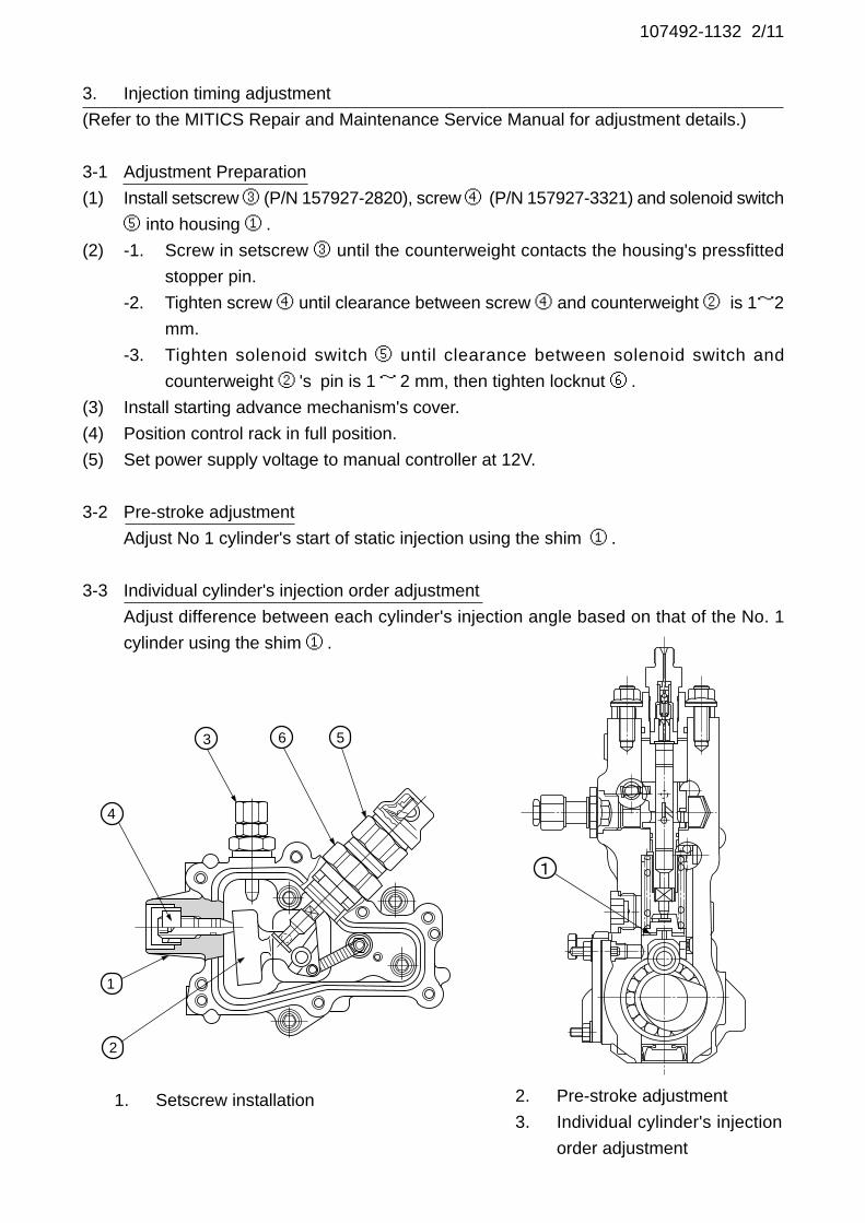
107492-1132 2/11
3. Injection timing adjustment
(Refer to the MITICS Repair and Maintenance Service Manual for adjustment details.)
3-1 Adjustment Preparation
(1) Install setscrew ③ (P/N 157927-2820), screw ④ (P/N 157927-3321) and solenoid switch
⑤ into housing ① .
(2) -1. Screw in setscrew ③ until the counterweight contacts the housing's pressfitted
stopper pin.
-2. Tighten screw ④ until clearance between screw ④ and counterweight ② is 1~2
mm.
-3. Tighten solenoid switch ⑤ until clearance between solenoid switch and
counterweight ② 's pin is 1~ 2 mm, then tighten locknut ⑥ .
(3) Install starting advance mechanism's cover.
(4) Position control rack in full position.
(5) Set power supply voltage to manual controller at 12V.
3-2 Pre-stroke adjustment
Adjust No 1 cylinder's start of static injection using the shim ① .
3-3 Individual cylinder's injection order adjustment
Adjust difference between each cylinder's injection angle based on that of the No. 1
cylinder using the shim ① .
1. Setscrew installation 2. Pre-stroke adjustment
3. Individual cylinder's injection
order adjustment
1
2
4
563

107492-1132 3/11
3-4 Measuring pre-stroke output voltage
(1) Install measuring device (P/N 105782-6420).
(2) Remove setscrew ③ (P/N 157927-2820) and install air bleeder bolt.
(3) Screw in screw ④ (P/N 157927-3321) and measure the No 1 cylinder's output voltage
for pre-stroke lift values in the table below.
Advice
If measuring device (P/N 105782-6420) is removed, the output voltage (a1, a2) should be
remeasured.
3-5 Minimum advance angle adjustment stopper adjustment
(1) Remove screw ④ (P/N 157927-3321) and install minimum advance angle adjustment
stopper.
(2) Screw in minimum advance angle adjustment stopper until No 1 cylinder's pre-stroke
is 3.67 ~ 3.73. Then, tighten locknut to specified torque.
(3) Measure the output voltage (c) at this time.
3-6 Solenoid switch adjustment
(1) Apply 24 V voltage to solenoid switch ⑤ .
(2) Loosen solenoid switch ⑤ until No 1 cylinder's pre-stroke is 1.90 ~ 2.03 mm, then
tighten locknut to specified torque.
(3) Confirm solenoid switch operates at 14.5 -0.1 V.
Adjusting pointConfirmation point
Pre-stroke (mm) Output voltage (actual) Remarks
a3.43 a1 + tolerance
3.17 a2 -tolerance
b2.85 b1 + tolerance
2.65 b2 -tolerance
(calculate from each specification)
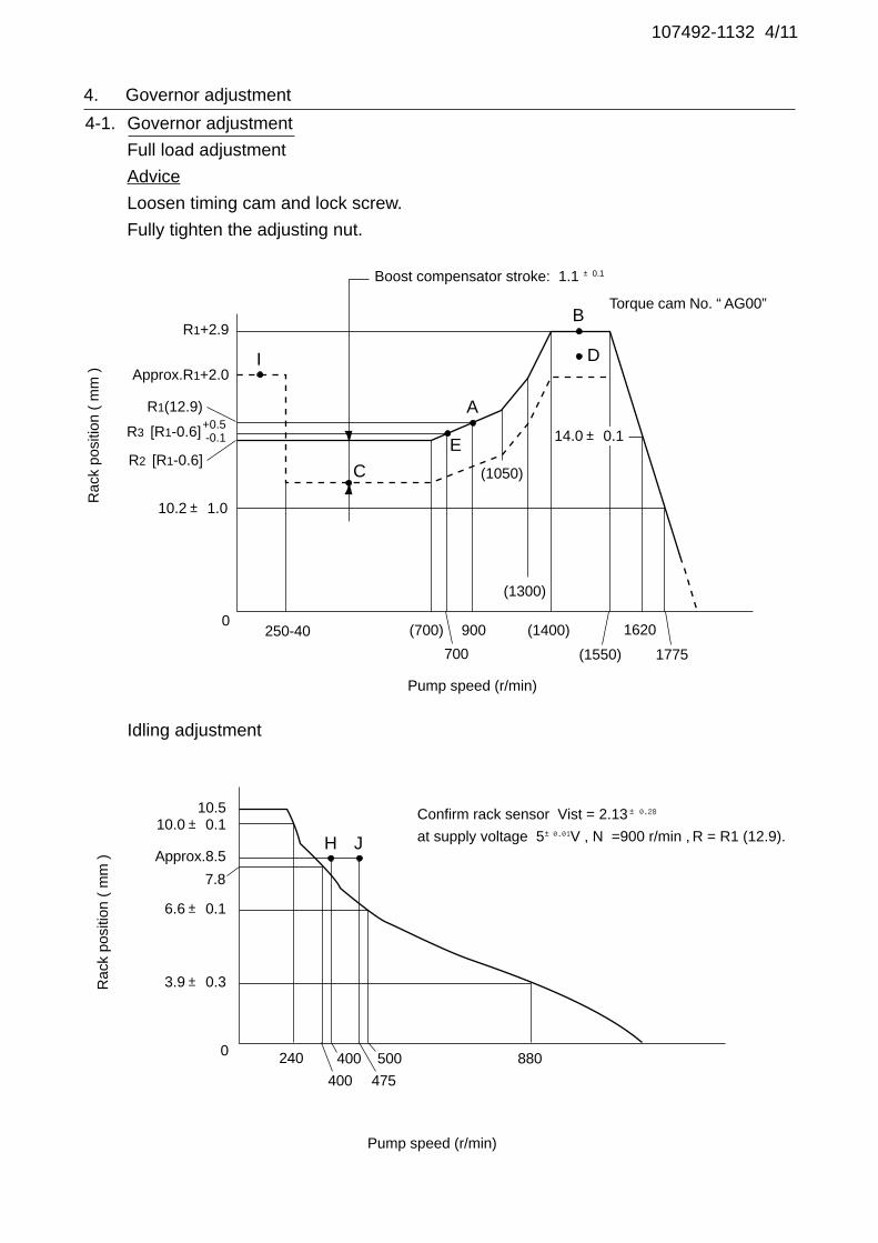
107492-1132 4/11
Rac
k po
sitio
n (
mm
)
Idling adjustment
Pump speed (r/min)
Rac
k po
sitio
n (
mm
)
Boost compensator stroke: 1.1 ±0.1
Torque cam No. “ AG00”
Pump speed (r/min)
Confirm rack sensor Vist = 2.13±0.28
at supply voltage 5±0.01V , N =900 r/min , R = R1 (12.9).
4. Governor adjustment
4-1. Governor adjustment
Full load adjustment
Advice
Loosen timing cam and lock screw.
Fully tighten the adjusting nut.
R1+2.9
Approx.R1+2.0
R1(12.9)
R2 [R1-0.6]
10.2± 1.0
0250-40 (700) 900 (1400)
(1550)
1620
1775
14.0± 0.1
A
B
D
C
I
10.510.0± 0.1
Approx.8.5
7.8
6.6± 0.1
3.9± 0.3
0 880500
475
400
400
240
H J
R3 [R1-0.6]+0.5-0.1
(1300)
700
E
(1050)
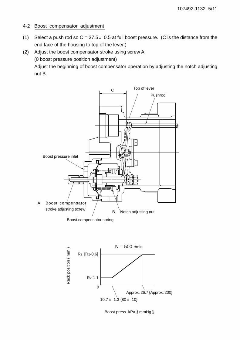
107492-1132 5/11
4-2 Boost compensator adjustment
(1) Select a push rod so C = 37.5±0.5 at full boost pressure. (C is the distance from the
end face of the housing to top of the lever.)
(2) Adjust the boost compensator stroke using screw A.
(0 boost pressure position adjustment)
Adjust the beginning of boost compensator operation by adjusting the notch adjusting
nut B.
Boost pressure inlet
A Boost compensator
stroke adjusting screw
Boost compensator spring
B Notch adjusting nut
Top of lever
Boost press. kPa{mmHg}
Rac
k po
sitio
n (
mm
) N = 500 r/min
R2 [R1-0.6]
R2-1.1
Approx. 26.7 {Approx. 200}
10.7± 1.3 {80± 10}
PushrodC
0
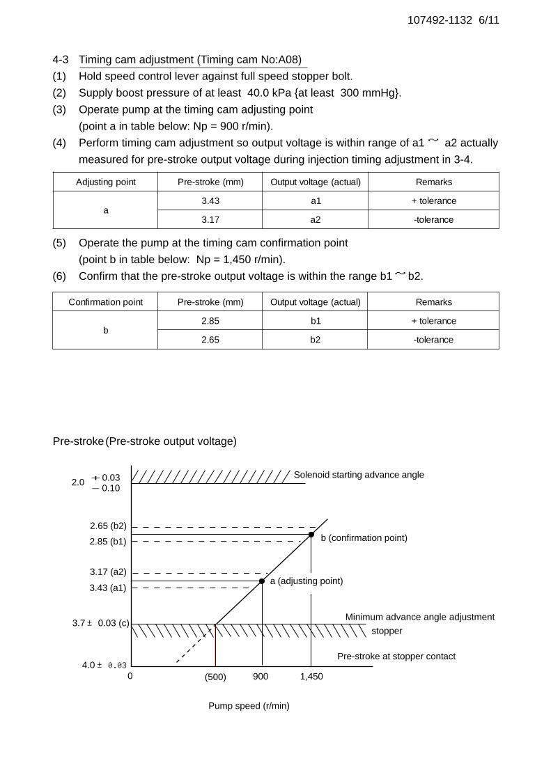
107492-1132 6/11
4-3 Timing cam adjustment (Timing cam No:A08)
(1) Hold speed control lever against full speed stopper bolt.
(2) Supply boost pressure of at least 40.0 kPa {at least 300 mmHg}.
(3) Operate pump at the timing cam adjusting point
(point a in table below: Np = 900 r/min).
(4) Perform timing cam adjustment so output voltage is within range of a1 ~ a2 actually
measured for pre-stroke output voltage during injection timing adjustment in 3-4.
(5) Operate the pump at the timing cam confirmation point
(point b in table below: Np = 1,450 r/min).
(6) Confirm that the pre-stroke output voltage is within the range b1~ b2.
Solenoid starting advance angle
b (confirmation point)
a (adjusting point)
Minimum advance angle adjustment
stopper
Pre-stroke(Pre-stroke output voltage)
Pump speed (r/min)
Pre-stroke at stopper contact
Adjusting point Pre-stroke (mm) Output voltage (actual) Remarks
a3.43 a1 + tolerance
3.17 a2 -tolerance
Confirmation point Pre-stroke (mm) Output voltage (actual) Remarks
b2.85 b1 + tolerance
2.65 b2 -tolerance
2.65 (b2)
2.85 (b1)
3.17 (a2)
3.43 (a1)
3.7± 0.03 (c)
4.0±0.03(500) 900 1,450
2.0 + 0.03- 0.10
0
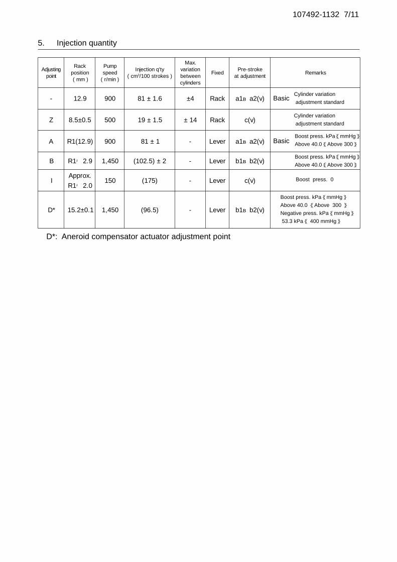
Adjustingpoint
Rackposition( mm )
Pumpspeed
( r/min )
Injection q'ty( cm3/100 strokes )
Max.variationbetweencylinders
FixedPre-stroke
at adjustmentRemarks
- 12.9 900 81 ± 1.6 ±4 Rack a1~a2(v)
Z 8.5±0.5 500 19 ± 1.5 ± 14 Rack c(v)
A R1(12.9) 900 81 ± 1 - Lever a1~a2(v)
B R1+2.9 1,450 (102.5) ± 2 - Lever b1~b2(v)
IApprox.
R1+2.0150 (175) - Lever c(v)
D* 15.2±0.1 1,450 (96.5) - Lever b1~b2(v)
107492-1132 7/11
5. Injection quantity
Cylinder variation
adjustment standardBasic
BasicBoost press. kPa{mmHg}Above 40.0{Above 300}
Cylinder variation
adjustment standard
Boost press. 0
Boost press. kPa{mmHg}Above 40.0 {Above 300 }Negative press. kPa{mmHg} 53.3 kPa{ 400 mmHg}
D*: Aneroid compensator actuator adjustment point
Boost press. kPa{mmHg}Above 40.0{Above 300}
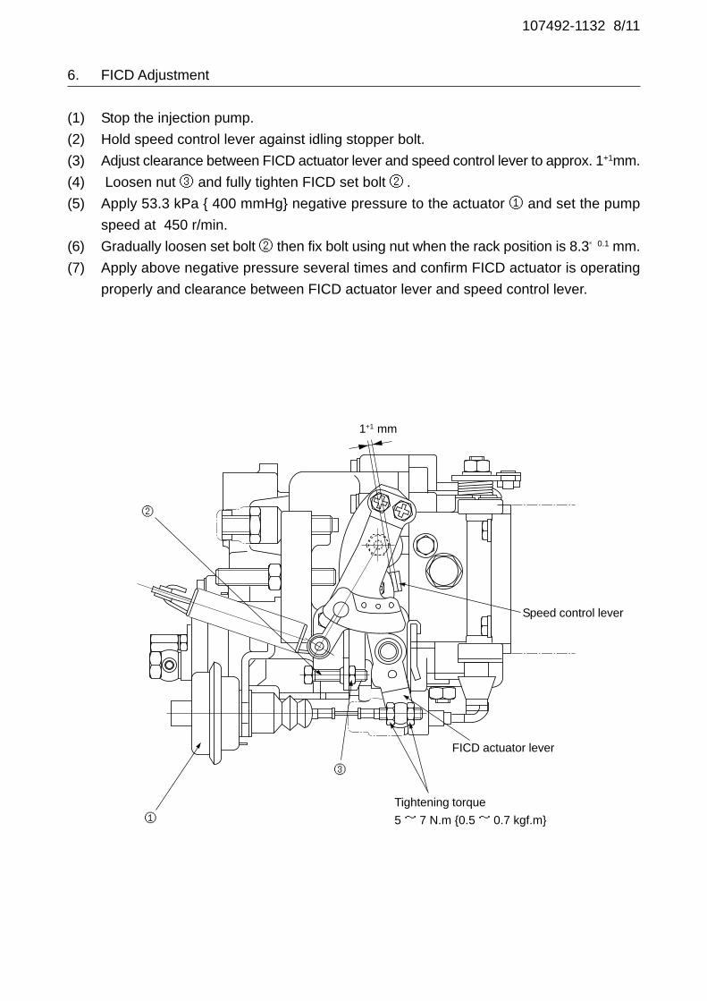
107492-1132 8/11
6. FICD Adjustment
(1) Stop the injection pump.
(2) Hold speed control lever against idling stopper bolt.
(3) Adjust clearance between FICD actuator lever and speed control lever to approx. 1+1mm.
(4) Loosen nut ③ and fully tighten FICD set bolt ② .
(5) Apply 53.3 kPa { 400 mmHg} negative pressure to the actuator ① and set the pump
speed at 450 r/min.
(6) Gradually loosen set bolt ② then fix bolt using nut when the rack position is 8.3±0.1 mm.
(7) Apply above negative pressure several times and confirm FICD actuator is operating
properly and clearance between FICD actuator lever and speed control lever.
Tightening torque
5 ~ 7 N.m {0.5 ~ 0.7 kgf.m}
FICD actuator lever
Speed control lever
②
1+1 mm
①
③
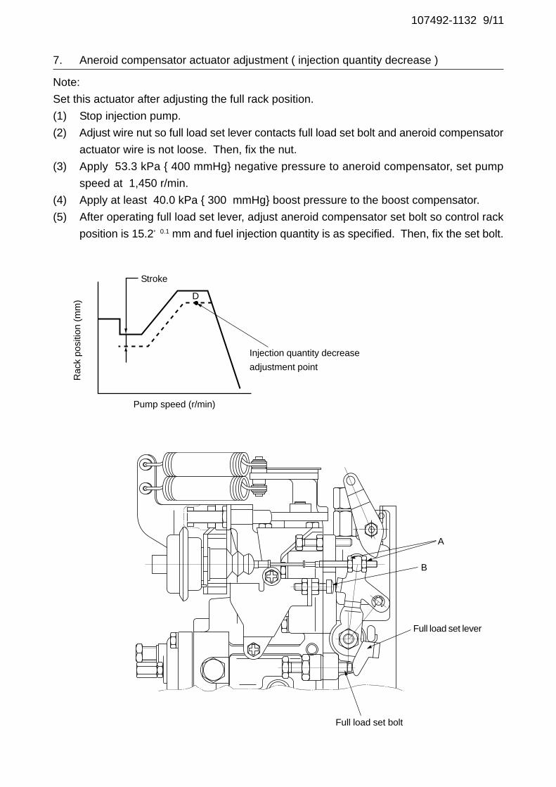
107492-1132 9/11
7. Aneroid compensator actuator adjustment ( injection quantity decrease )
Note:
Set this actuator after adjusting the full rack position.
(1) Stop injection pump.
(2) Adjust wire nut so full load set lever contacts full load set bolt and aneroid compensator
actuator wire is not loose. Then, fix the nut.
(3) Apply 53.3 kPa { 400 mmHg} negative pressure to aneroid compensator, set pump
speed at 1,450 r/min.
(4) Apply at least 40.0 kPa { 300 mmHg} boost pressure to the boost compensator.
(5) After operating full load set lever, adjust aneroid compensator set bolt so control rack
position is 15.2±0.1 mm and fuel injection quantity is as specified. Then, fix the set bolt.
Stroke
Injection quantity decrease
adjustment point
Full load set lever
Full load set bolt
D
Rac
k po
sitio
n (m
m)
Pump speed (r/min)
B
A

107492-1132 10/11
8. Speed control lever angle 9. Stop lever angle
Hole(R42)Stopper bolt H position
Idling
Full-speedHole(R41.3)
Set the position
R=1.5± 0.2
StopNormal
45°±5°
22.5°±5°
30°±5°
29°± 3°
10. Rack Sensor Adjustment
(1) Before removing rack position measuring device, apply at least 40.0 kPa
{at least 300 mmHg} boost pressure and confirm rack position is R1 = 12.9 mm and
fuel injection quantity is 81± 1 mm3/st at N = 900 r/min.
(2) Remove rack position measuring device.
(3) Attach rack sensor core to control rack.
At this time, hold control rack using a spanner (to prevent the rack from bending).
Specified torque : 3.4~~~~~ 4.9 N.m {0.35~~~~~ 0.5 kgf.m}
(4) While pulling stop lever, install rack sensor to rack sensor core.
(5) Tighten two flange fixing screws.
Specified torque : 6.9~~~~~ 8.8 N.m {0.7~~~~~ 0.9 kgf.m}
(6) Connect rack sensor wire harness to constant voltage power supply and digital voltmeter.
(7) Turn constant voltage power supply power switch ON and set it to DC 5± 0.01V.
(8) Apply at least 40.0 kPa {at least 300 mmHg} boost pressure, set pump speed at
N= 900 r/min, and hold speed control lever against the full speed stopper bolt.
(9) Confirm the rack sensor output voltage from the digital voltmeter. (Vist = 2.13±0.28)
(10) Confirm that the voltage changes when the speed control lever is moved to the idle and
full sides.
Rac
k po
sitio
n (m
m)
R1
N
Pump speed (r/min)
Sen
sor
outp
ut v
olta
ge (
V)
Vist
R1
Rack position (mm)
A

107492-1132 11/11
Timing setting
At No. 1 plunger’s beginning
of injection position
B.T.D.C. : 8°
(At pre-stroke 3.7± 0.05mm)
Pump
Engine
Bracket mark
Gear hole (Dia. 3mm)
Gear’s threaded hole
Gear side
Pump side
Stamp on coupling and bracket
(B.T.D.C. 8°°°°°)
Mark position of coupling at B.T.D.C. 13°°°°°
Check hole
28°35′14″±
20′
13°21′18″± 3°
(35°)
(96°)
(3°12′32″)
11. Drive Coupling Timing

Governor: EP/RED-IV105961-0071
DIGI switch No.: 14 (For C/U 407980-224*)
Oil Temp. 40+5 °C
Bosch Automotive Systems Corporation
Service Department
3-4-1 Kitano, Niiza-shi, Saitama-ken, 352-8572 Japan
Tel. (048)470-1559, Fax. (048)474-9856
Company:
Ass'y No.: 107691-0144ENGINE MODEL: FE6TA
No.
1. Test conditions
Date:
Pump rotation: clockwise ( viewed from drive side )
Injection pump: TC6MD
kgf/cm2 }
CONFIDENTIAL
INJECTION PUMP CALIBRATION DATA
18 Sep 2002
NISSAN DIESEL
16801 Z5607
107069-1460
Injection pipe: Outer Dia. 8 mm × Inner Dia. 3 mm Length 600 mm
Nozzle opening pressure: 20.7 MPa { 211 kgf/cm2 }
Nozzle: 105780-0120 Nozzle Holder: 105780-2190(Bosch Type No. 1 688 901 990) (Bosch Type No. )
Nozzle & Nozzle Holder Ass'y: 105780-8250 (Bosch Type No. 1 688 901 101)
Overflow valve opening pressure: 255 kPa { 2.6 kgf/cm2 }
Test Oil: ISO4113 or SAE Standard Test Oil { SAE J967d }
8
Transfer pump pressure: 255 kPa { 2.6
1/4
Pre-stroke actuator:159645-2020
2. Stop lever adjustment
37°±
5°
20°±
5°
3. Confirmation of RED-IV governor's output characteristics
[1] Rack sensor output characteristics(1) Measure the rack position R2 at PWM 72.5% and confirm that R2 = 15±1 mm.
(2) Measure the rack position R1 at PWM16.25% and confirm that R2 - R1 = 10±0.1 mm.
R1 R2
72.5%
16.25%
PWM (%)
Rack position (mm)
Switch box part no. 407980-4340
Control unit part no. 407915-0590
PWM72.5% rack position R2 = 15±1 (mm)
PWM16.25% rack characteristics R2 - R1 = 10±0.1 (mm)
R=1.0
Stop
Normal
R=20.0
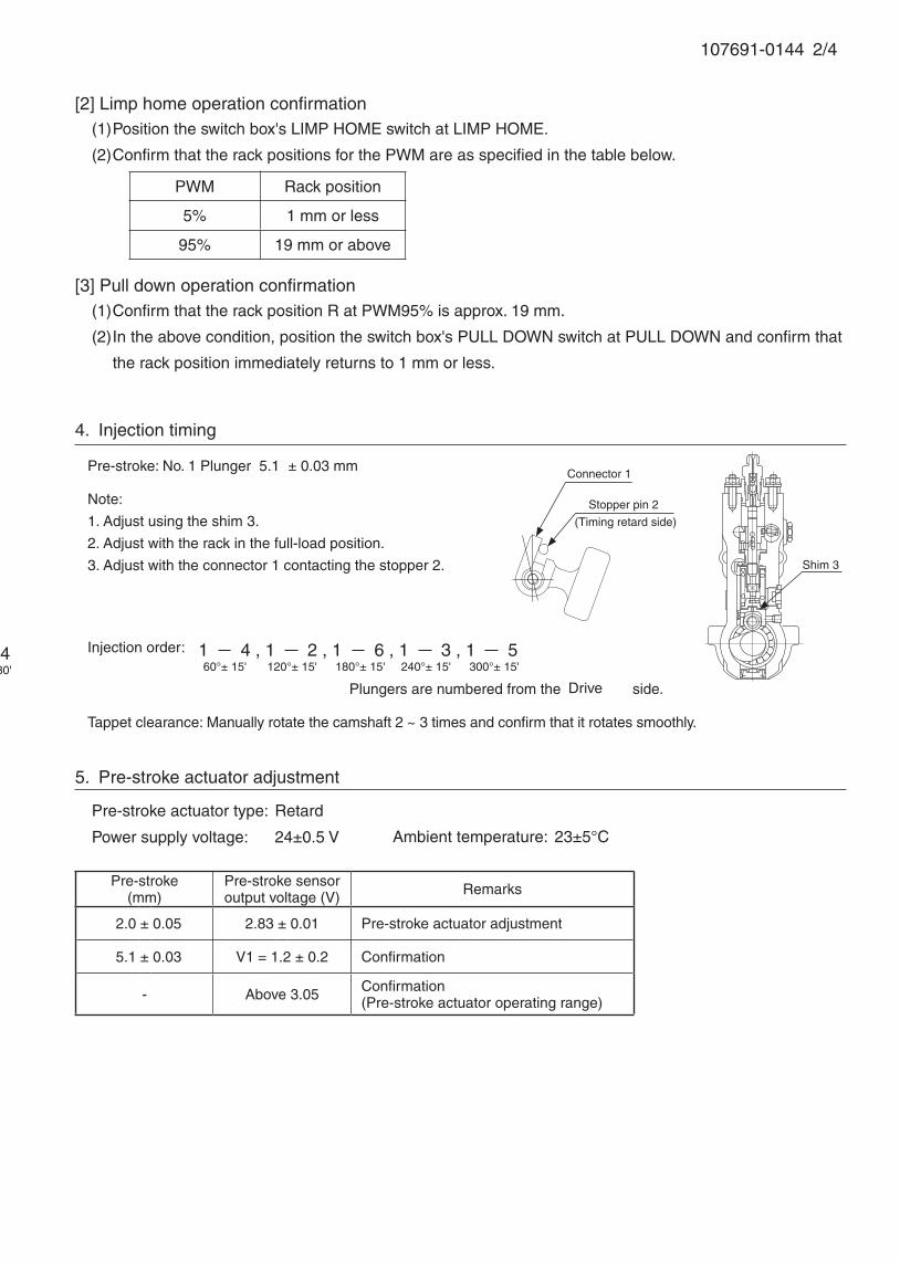
107691-0144 2/4
Pre-stroke(mm)
Pre-stroke sensoroutput voltage (V) Remarks
2.0 ± 0.05 2.83 ± 0.01 Pre-stroke actuator adjustment
5.1 ± 0.03 V1 = 1.2 ± 0.2 Confirmation
- Above 3.05 Confirmation(Pre-stroke actuator operating range)
Note:
1. Adjust using the shim 3.
2. Adjust with the rack in the full-load position.
3. Adjust with the connector 1 contacting the stopper 2.
Injection order:
4. Injection timing
Pre-stroke: No. 1 Plunger 5.1 ± 0.03 mm
Plungers are numbered from the side.
1 5 , 1 3 , 1 6 , 1 2 , 1 4300°± 30'
Tappet clearance: Manually rotate the camshaft 2 ~ 3 times and confirm that it rotates smoothly.
Shim 3
5. Pre-stroke actuator adjustment
Pre-stroke actuator type: Retard
Power supply voltage: 24±0.5 V Ambient temperature: 23±5°C
Connector 1
Stopper pin 2
(Timing retard side)
1 4 , 1 2 , 1 6 , 1 3 , 1 560°± 15' 120°± 15' 180°± 15' 240°± 15' 300°± 15'
[2] Limp home operation confirmation(1) Position the switch box's LIMP HOME switch at LIMP HOME.
(2) Confirm that the rack positions for the PWM are as specified in the table below.
[3] Pull down operation confirmation(1) Confirm that the rack position R at PWM95% is approx. 19 mm.
(2) In the above condition, position the switch box's PULL DOWN switch at PULL DOWN and confirm that
the rack position immediately returns to 1 mm or less.
PWM Rack position
5% 1 mm or less
95% 19 mm or above
Drive

107691-0144 3/4
Injection pump
Stamping position
Pre-stroke actuator
6. Injection quantity
P = pre-stroke sensor output at injection quantity adjustment
P1 V = 2.25 ± 0.01 (V) 3.1 ± 0.05 (mm)
P2 V = V1 + 0.05 ± 0.01 (V) 5.0 ± 0.03 (mm)
PRack
position(mm)
PWM(%)
Pumpspeed(r/min)
Injection q'ty(cm3 / 1000 strokes )
Max. variationbetween
cylinders (%)Remarks
P1 (11.3) 51.5 700 108 ± 1 ± 4 Basic
P2 (6.7) Approx 25.6 445 11 ± 1.8 ± 10
Pump speed(r/min)
Below 1150 1100 1300
Advanceangle (° )
Start 0 Below 0.3 Finish
4.0 ± 0.3
7. Timing advance specification
Note:
1. Move the pre-stroke actuator fully counter clockwise (viewed from the drive side), and temporarily secure it to the actuator housing using the bolts.Tightening torque: 1.0 ~ 1.5 N•m {0.1 ~ 0.15 kgf•m}
2. Move the pre-stroke actuator clockwise (viewed from the drive side) to adjust it.
3. After pre-stroke actuator adjustment, stamp both the pre-stroke actuator and the housing with an aligning mark.
107691-0144 4/4
1. Turn the pre-stroke actuator OFF.
2. Position the camshaft in the No.1 plunger's beginning of injection position.
3. Confirm that the injection pump pointer's aligning mark and the flywheel's aligning mark are aligned.
4. If not aligned, remove the incorrect flywheel aligning mark and remark it.
5. Confirm that the center of the flywheel's threaded hole is as specified.
8. Injection timing setting
At No. 1 plunger’s beginning of injection position(Pre-stroke: 5.1±0.03 mm)
Injection timing aligning mark
Pointer
Flywheel
(Actual shapes and positions may differfrom the illustration.)
Approx. 25°Coupling key groove position

Actuator: EP/RED-III 105956-0112
DIGI switch No.: 17 (For C/U 407980-224*)
Oil Temp. 40+5 °C
Bosch Automotive Systems Corporation
Service Department
3-4-1 Kitano, Niiza-shi, Saitama-ken, 352-8572 Japan
Tel. (048)470-1559, Fax. (048)474-9856
Company:
Ass'y No.: 107691-2930ENGINE MODEL: 6D16T3
No.
1. Test conditions
Date:
Pump rotation: Counter clockwise ( viewed from drive side )
Injection pump: TC6MD
kgf/cm2 }
CONFIDENTIAL
INJECTION PUMP CALIBRATION DATA
29 Oct 2002
ME301247
107069-0590
Injection pipe: Outer Dia. 8 mm × Inner Dia. 3 mm Length 600 mm
Nozzle opening pressure: 20.7 MPa { 211 kgf/cm2 }
Nozzle: 105780-0120 Nozzle Holder: 105780-2190(Bosch Type No. 1 688 901 990) (Bosch Type No. )
Nozzle & Nozzle Holder Ass'y: 105780-8250 (Bosch Type No. 1 688 901 101)
Overflow valve opening pressure: 255 ± 34 kPa { 2.6 ± 0.35 kgf/cm2 }
Test Oil: ISO4113 or SAE Standard Test Oil { SAE J967d }
0
Transfer pump pressure: 255 kPa { 2.6
1/4
Pre-stroke actuator:159601-5420
MITSUBISHI
2. Stop lever adjustment
3. RED-III governor
Confirmation of the control rack position sensor's output characteristics
(Rack 19mm, Span 6mm)
When the rack sensor output voltages are V1 and V2, confirm that rack positions R1 and R2 are as
specified below.
Rack type 19 mm
Control unit no. 407910-3960
Output voltageV1 = (V2+0.9±0.0075)
V2 = 2.2±0.01
Rack position (mm)R2 = 11±1
R2 - R1 = 6±0.05
Rack position (mm)R1 R2
Out
put v
olta
ge (
V)
V1
V2
39°±5° R=20.0
Stop Normal
37°±5°
R=1.0
107691-2930 2/4
Pre-stroke(mm)
Pre-stroke sensoroutput voltage (V) Remarks
2.0 ± 0.05 2.83 ± 0.01 Pre-stroke actuator adjustment
5.1 ± 0.03 V1 = 1.2 ± 0.2 Confirmation
- Above 3.05 Confirmation(Pre-stroke actuator operating range)
Note:
1. Adjust using the shim 3.
2. Adjust with the rack in the full-load position.
3. Adjust with the connector 1 contacting the stopper 2.
Injection order:
4. Injection timing
Pre-stroke: No. 1 Plunger 5.1 ± 0.03 mm
Plungers are numbered from the Governor side.
1 5 , 1 3 , 1 6 , 1 2 , 1 4
Tappet clearance: Manually rotate the camshaft 2 ~ 3 times and confirm that it rotates smoothly.
Shim 3
5. Pre-stroke actuator adjustment
Pre-stroke actuator type: Retard
Power supply voltage: 24±0.5 V Ambient temperature: 23±5°C
(Timing retard side)
Connector 1
Stopper 2
1 5 , 1 3 , 1 6 , 1 2 , 1 460°± 15' 120°± 15' 180°± 15' 240°± 15' 300°± 15'
Note:
1. Move the pre-stroke actuator fully counter clockwise (viewed from the drive side), and temporarily secure it to the actuator housing using the bolts.Tightening torque: 1.0 ~ 1.5 N•m {0.1 ~ 0.15 kgf•m}
2. Move the pre-stroke actuator clockwise (viewed from the drive side) to adjust it.
3. After pre-stroke actuator adjustment, stamp both the pre-stroke actuator and the housing with an aligning mark.
Stamping position
Pre-stroke actuatorInjection pump

107691-2930 3/4
6. Injection quantity
P = pre-stroke sensor output at injection quantity adjustment
P1 V = 2.25 ± 0.01 (V) 3.1 ± 0.05 (mm)
P2 V = V1 + 0.05 ± 0.01 (V) 5.0 ± 0.03 (mm)
PRack
position(mm)
Vist(V)
Pumpspeed(r/min)
Injection q'ty(cm3 / 1000 strokes )
Max. variationbetween
cylinders (%)Remarks
P1 (12.5) 1.98 800 140 ± 1 ± 3 Basic
P2 (6.6) 2.9 ± 0.1 395 16.5 ± 1.8 ± 15
Pump speed(r/min)
Below1050 1000 1075
Advanceangle (° )
Start0 0 - 0.5 Finish
-1.5±0.5
8. Timing advance specification
1. Turn the pre-stroke actuator OFF.
2. Position the camshaft in the No.1 plunger's beginning of injection position.
3. Confirm that the injection pump pointer's aligning mark and the flywheel's aligning mark are aligned.
4. If not aligned, remove the incorrect flywheel aligning mark and remark it.
5. Confirm that the center of the flywheel's threaded hole is as specified.
9. Injection timing setting
At No. 1 plunger’s beginning of injection position(Pre-stroke: 5.1±0.03 mm)
Injection timing aligning mark
Pointer
Flywheel
(Actual shapes and positions may differfrom the illustration.)
Coupling key groove positionApprox.2°
Adjust the clearance between the pickup and the gear tooth to 1-0.2mm.
B.T.D.C.: 2°

107691-2930 4/4
7. Drive side rack sensor adjustment (-0620)• Threaded type rack sensor (For REDIII governor)
(1) Screw in bobbin 1 until it contacts the joint 2.
(2) When the governor side rack sensor output is VG, adjust the depth that the bobbin 1 is screwed in so
that the drive side rack sensor output voltage is VR±0.01V. Then, fix using the nut 5.
5
4 3
Pump end face
Apply red paint21
Rack sensor power supply 5±0.01V
Governor side rack sensor output VG 1.60V
Drive side rack sensor output voltage VR±0.01V
(3) Reset the governor side rack sensor output at VG and confirm that the drive side rack sensor output
voltage is VR±0.01V.
(4) Attach the caution plate to the top of the joint 2 and apply red paint to the joint 2 and nut 5 join and to
the pump end face and joint 2 join.
Note:
When adjusting the depth that the bobbin 1 is screwed into the joint 2, the fully tightened position of the
bobbin is 9 threads (ie, 9 turns) from where it first engages the threads.
VR Control unit part no.
2V407912-1742
105782-6320
3V
407910-3032
407910-6010
407910-7210

Pre-stroke(mm)
Pre-stroke sensoroutput voltage (V) Remarks
2.0 ± 0.05 2.83 ± 0.01 Pre-stroke actuator adjustment
5.1 ± 0.03 V1 = 1.2 ± 0.2 Confirmation
- Above 3.05 Confirmation(Pre-stroke actuator operating range)
Note:
1. Adjust using the shim 3.
2. Adjust with the rack in the full-load position.
3. Adjust with the connector 1 contacting the stopper 2.
Injection order:
2. Injection timing
Pre-stroke: No. 1 Plunger 5.1 ± 0.03 mm
Plungers are numbered from the Governor side.
Tappet clearance: Manually rotate the camshaft 2 ~ 3 times and confirm that it rotates smoothly.
Shim 3
DIGI switch No.: 17 (For C/U 407980-224*)
Oil Temp. 40+5 °C
Bosch Automotive Systems Corporation
Service Department
3-4-1 Kitano, Niiza-shi, Saitama-ken, 352-8572 Japan
Tel. (048)470-1559, Fax. (048)474-9856
Company:
Ass'y No.: 107691-3570ENGINE MODEL: J08C-UJ
No. Governor: EP/RLD-J
1. Test conditions
Date:
Pump rotation: Counter clockwise ( viewed from drive side )
Injection pump: TC6MD105933-1700
kgf/cm2 }
CONFIDENTIAL
INJECTION PUMP CALIBRATION DATA
29 Nov 2002
22040-2341B
107069-0740
Injection pipe: Outer Dia. 8 mm × Inner Dia. 3 mm Length 600 mm
Nozzle opening pressure: 20.7 MPa { 211 kgf/cm2 }
Nozzle: 105780-0120 Nozzle Holder: 105780-2190(Bosch Type No. 1 688 901 990) (Bosch Type No. )
Nozzle & Nozzle Holder Ass'y: 105780-8250 (Bosch Type No. 1 688 901 101)
Test Oil: ISO4113 or SAE Standard Test Oil { SAE J967d }
1
Transfer pump pressure: 255 kPa { 2.6
1/6
Pre-stroke actuator:159645-4120
3. Pre-stroke actuator adjustment
Pre-stroke actuator type: Retard
Power supply voltage: 24±0.5 V Ambient temperature: 23±5°C
(Timing retard side)
Connector 1
Stopper 2
1 4 , 1 2 , 1 6 , 1 3 , 1 560°± 15' 120°± 15' 180°± 15' 240°± 15' 300°± 15'
HINO
Overflow valve opening pressure: 255 ± 34 kPa { 2.6 ± 0.35 kgf/cm2 }
107691-3570 2/6
Note:
1. Move the pre-stroke actuator fully clockwise (viewed from the drive side), and temporarily secure it to the actuator
housing using the bolts.
Tightening torque: 1.0 ~ 1.5 N•m {0.1 ~ 0.15 kgf•m}
2. Move the pre-stroke actuator counter clockwise (viewed from the drive side) to adjust it.
3. After pre-stroke actuator adjustment, stamp both the pre-stroke actuator and the housing with an aligning mark.
Injection pump
Stamping position
Pre-stroke actuator
Adjustingpoint
PRack
position(mm)
Pumpspeed(r/min)
Injection q'ty(cm3 / 1000 strokes )
Max. variationbetween
cylinders (%)Fixed Remarks
- P1 12.7 750 114.5 ± 3 ± 3.5 Rack Basic
Z P2 8.2±0.5 440 - Rack Adjust injection q'ty at N = 440.Adjust governor as per gov. adj. spec.
4. Injection quantity variation rate adjustment
P = pre-stroke sensor output at injection quantity adjustment
P1 V = 2.25 ± 0.01 (V) 3.1 ± 0.05 (mm)
P2 V =V1 + 0.05±0.01 (V) 5.0 ± 0.03 (mm)
Each cylinder 13.5±1.35
107691-3570 3/6
If not indicated, the rack position allowance is ± 0.05 mm.
5. Governor adjustment
0190
275350 700
Rac
k po
sitio
n (m
m)
Pump speed (r/min)
10.0
9.7+0.2-0.3
R1(12.7)
R1+1.1
0Below 225
(500)
(1300)
A
B
Rac
k po
sitio
n (m
m)
Pump speed (r/min)
Torque cam no. ‘AH02’
R1+2.05
Approx R1+0.25
(800)
(950)
(1200) (1470)
1510
400
5.1±0.6
8.0Approx 8.2
Full load adjustment
Idling adjustment
Stop lever normal position setting: (18.0)
Boost compensator stroke: 1.15±0.1
12.3±0.1
R2[R1-1.0]
9.3±1.0
1575
6.7±0.1
R2[R1-1.0]
R2-1.15
0
36.0±1.3 {270±10}
Approx 48.7 {Approx 365}
N = 300
Rac
k po
sitio
n (m
m)
Boost pressure kPa {mmHg}
Boost compensator adjustment
I
(1050)
R1-0.25
650 (700)
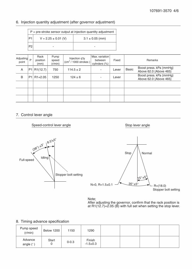
7. Control lever angle
Pump speed(r/min)
Below 1200 1150 1290
Advanceangle (° )
Start0 0 -0.3 Finish
-1.5±0.3
8. Timing advance specification
107691-3570 4/6
Adjustingpoint
PRack
position(mm)
Pumpspeed(r/min)
Injection q'ty(cm3 / 1000 strokes )
Max. variationbetween
cylinders (%)Fixed Remarks
A P1 R1(12.7) 750 114.5 ± 2 - Lever Boost press. kPa {mmHg} Above 62.0 {Above 465}
B P1 R1+2.05 1250 124 ± 6 - Lever Boost press. kPa {mmHg} Above 62.0 {Above 465}
6. Injection quantity adjustment (after governor adjustment)
P = pre-stroke sensor output at injection quantity adjustment
P1 V = 2.25 ± 0.01 (V) 3.1 ± 0.05 (mm)
P2 - -
(38°) ±3°
Speed-control lever angle
Idling
Stopper bolt setting
Stop lever angle
N=0, R=1.5±0.1
Stop
Full-speed
Normal
8.5°±5°
35°±5°
15°±5°
R=(18.0)Stopper bolt setting
Note;After adjusting the governor, confirm that the rack position is at R1(12.7)+2.05 (B) with full set when setting the stop lever.
Basic

107691-3570 5/6
1. Turn the pre-stroke actuator OFF.
2. Position the camshaft in the No.1 plunger's beginning of injection position.
3. Confirm that the injection pump pointer's aligning mark and the flywheel's aligning mark are aligned.
4. If not aligned, remove the incorrect flywheel aligning mark and remark it.
5. Confirm that the center of the flywheel's threaded hole is as specified.
9. Injection timing setting
At No. 1 plunger’s beginning of injection position(Pre-stroke: 5.1±0.03 mm)
Injection timing aligning mark
Pointer
Flywheel
(Actual shapes and positions may differfrom the illustration.)
Coupling key groove positionApprox.30°

107691-3570 6/6
10. Rack sensor adjustment
Amp-equipped rack sensor adjustment (154610-5*20)• Threaded type rack sensor (without rack limit; for P type, TICS)
(1) Screw in bobbin 1 until it contacts the joint 2.
(2) Fix the pump lever at full and screw in the bobbin 1 to adjust the depth so that the amp’s output
voltage V = VR at Np = No and R = Ro. Then, fix the rack sensor using the nut 6.
(3) Move the pump lever 2 or 3 times, reset at full and confirm that the amp’s output voltage V = VR.
(4) Attach the caution plate to the top of the joint 2 and apply red paint to the joint 2 - nut 6 join, and the
pump end face - joint 2 join.
Note:
(1) When adjusting the bobbin 1 and joint 2, the fully tightened position of the bobbin is 9 threads (ie, 9
turns) from where it first engages the joint.
(2) With the welded rack block type, refer to the table below for the R = Ro range (the range varies with
the joint).
Rack sensor power supply 5±0.01V
Speed No 1250 r/min
Rack position Ro R1(12.7) + 2.05 mm
Output voltage VR 3.00±0.01V
Threaded rack block type Welded rack block type
6 1 2
5 4 3
Apply red paint
Pump end face
6 1 2 Apply red paint
Pump end face
4 3
Rack sensor adjusting position
Ro
No Np
Rac
k po
sitio
n Output voltage
VR
Ro
Adjustment Np = No
Joint part no. Ro
154614-2500 10.2 ~ 13.7
154614-4800 5.2 ~ 8.7
154614-8300 15.2 ~ 18.7
154614-8400 20.2 ~ 23.7
154614-8700 7.7 ~ 11.2
154614-8800 12.7 ~ 16.2
154614-8900 17.7 ~ 21.2
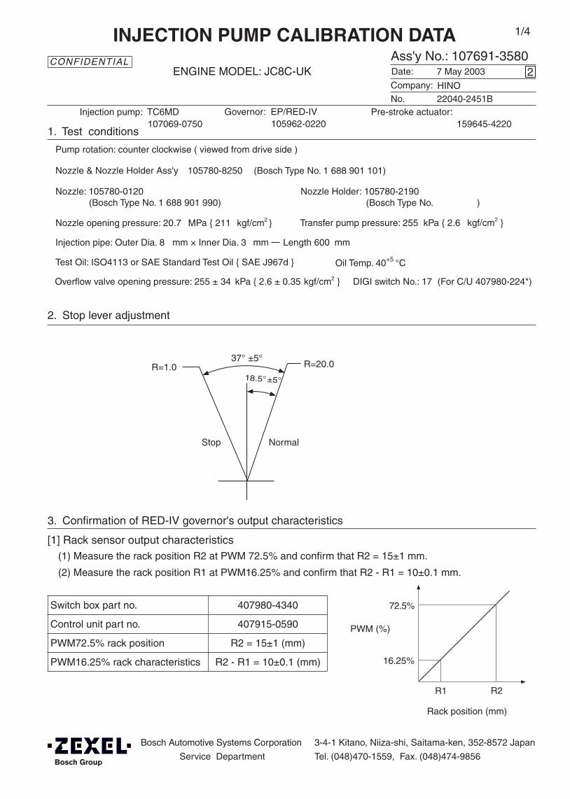
Governor: EP/RED-IV105962-0220
DIGI switch No.: 17 (For C/U 407980-224*)
Oil Temp. 40+5 °C
Bosch Automotive Systems Corporation
Service Department
3-4-1 Kitano, Niiza-shi, Saitama-ken, 352-8572 Japan
Tel. (048)470-1559, Fax. (048)474-9856
Company:
Ass'y No.: 107691-3580ENGINE MODEL: JC8C-UK
No.
1. Test conditions
Date:
Pump rotation: counter clockwise ( viewed from drive side )
Injection pump: TC6MD
kgf/cm2 }
CONFIDENTIAL
INJECTION PUMP CALIBRATION DATA
7 May 2003
22040-2451B
107069-0750
Injection pipe: Outer Dia. 8 mm × Inner Dia. 3 mm Length 600 mm
Nozzle opening pressure: 20.7 MPa { 211 kgf/cm2 }
Nozzle: 105780-0120 Nozzle Holder: 105780-2190(Bosch Type No. 1 688 901 990) (Bosch Type No. )
Nozzle & Nozzle Holder Ass'y: 105780-8250 (Bosch Type No. 1 688 901 101)
Test Oil: ISO4113 or SAE Standard Test Oil { SAE J967d }
2
Transfer pump pressure: 255 kPa { 2.6
1/4
Pre-stroke actuator:159645-4220
HINO
2. Stop lever adjustment
3. Confirmation of RED-IV governor's output characteristics
[1] Rack sensor output characteristics(1) Measure the rack position R2 at PWM 72.5% and confirm that R2 = 15±1 mm.
(2) Measure the rack position R1 at PWM16.25% and confirm that R2 - R1 = 10±0.1 mm.
R1 R2
72.5%
16.25%
PWM (%)
Rack position (mm)
Switch box part no. 407980-4340
Control unit part no. 407915-0590
PWM72.5% rack position R2 = 15±1 (mm)
PWM16.25% rack characteristics R2 - R1 = 10±0.1 (mm)
R=1.0
Stop Normal
R=20.0
Overflow valve opening pressure: 255 ± 34 kPa { 2.6 ± 0.35 kgf/cm2 }
37° ±5°
18.5°±5°
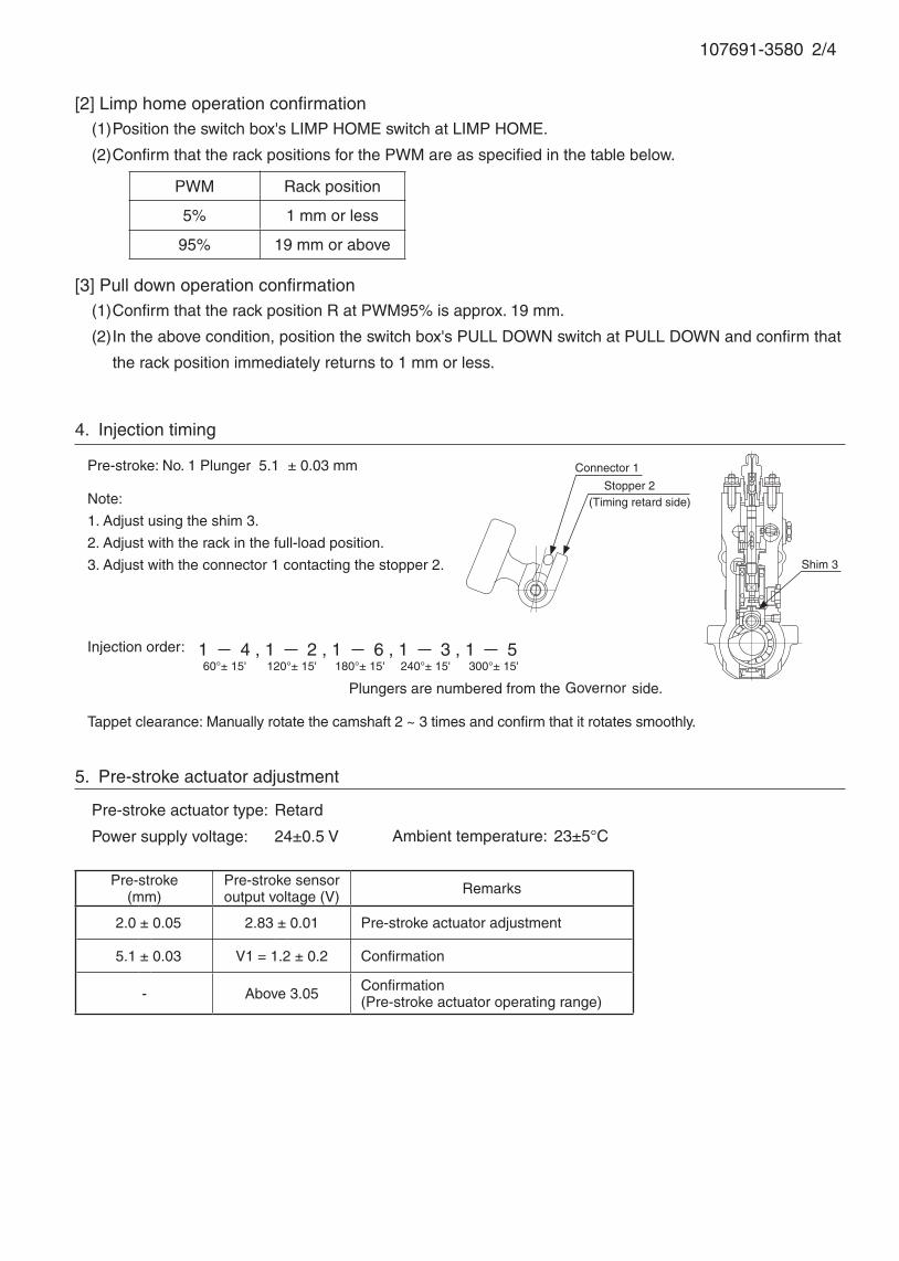
107691-3580 2/4
Pre-stroke(mm)
Pre-stroke sensoroutput voltage (V) Remarks
2.0 ± 0.05 2.83 ± 0.01 Pre-stroke actuator adjustment
5.1 ± 0.03 V1 = 1.2 ± 0.2 Confirmation
- Above 3.05 Confirmation(Pre-stroke actuator operating range)
Note:
1. Adjust using the shim 3.
2. Adjust with the rack in the full-load position.
3. Adjust with the connector 1 contacting the stopper 2.
Injection order:
4. Injection timing
Pre-stroke: No. 1 Plunger 5.1 ± 0.03 mm
Plungers are numbered from the side.
Tappet clearance: Manually rotate the camshaft 2 ~ 3 times and confirm that it rotates smoothly.
Shim 3
5. Pre-stroke actuator adjustment
Pre-stroke actuator type: Retard
Power supply voltage: 24±0.5 V Ambient temperature: 23±5°C
(Timing retard side)
Connector 1
Stopper 2
1 4 , 1 2 , 1 6 , 1 3 , 1 560°± 15' 120°± 15' 180°± 15' 240°± 15' 300°± 15'
[2] Limp home operation confirmation(1) Position the switch box's LIMP HOME switch at LIMP HOME.
(2) Confirm that the rack positions for the PWM are as specified in the table below.
[3] Pull down operation confirmation(1) Confirm that the rack position R at PWM95% is approx. 19 mm.
(2) In the above condition, position the switch box's PULL DOWN switch at PULL DOWN and confirm that
the rack position immediately returns to 1 mm or less.
PWM Rack position
5% 1 mm or less
95% 19 mm or above
Governor
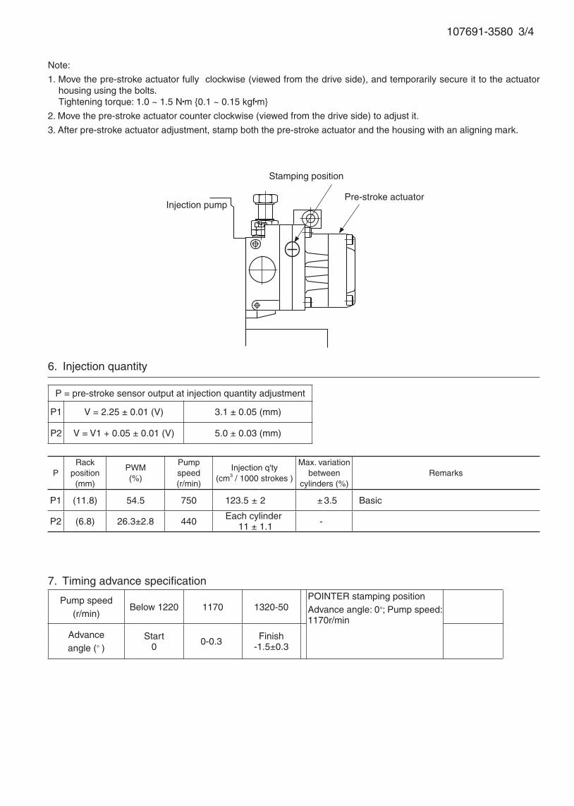
107691-3580 3/4
Injection pump
Stamping position
Pre-stroke actuator
6. Injection quantity
P = pre-stroke sensor output at injection quantity adjustment
P1 V = 2.25 ± 0.01 (V) 3.1 ± 0.05 (mm)
P2 V = V1 + 0.05 ± 0.01 (V) 5.0 ± 0.03 (mm)
PRack
position(mm)
PWM(%)
Pumpspeed(r/min)
Injection q'ty(cm3 / 1000 strokes )
Max. variationbetween
cylinders (%)Remarks
P1 (11.8) 54.5 750 123.5 ± 2 ± 3.5 Basic
P2 (6.8) 26.3±2.8 440 -
7. Timing advance specification
Note:
1. Move the pre-stroke actuator fully clockwise (viewed from the drive side), and temporarily secure it to the actuator housing using the bolts.Tightening torque: 1.0 ~ 1.5 N•m {0.1 ~ 0.15 kgf•m}
2. Move the pre-stroke actuator counter clockwise (viewed from the drive side) to adjust it.
3. After pre-stroke actuator adjustment, stamp both the pre-stroke actuator and the housing with an aligning mark.
Each cylinder 11 ± 1.1
Pump speed(r/min)
Below 1220 1170 1320-50POINTER stamping positionAdvance angle: 0°; Pump speed: 1170r/min
Advanceangle (° )
Start0 0- 0.3 Finish
-1.5±0.3
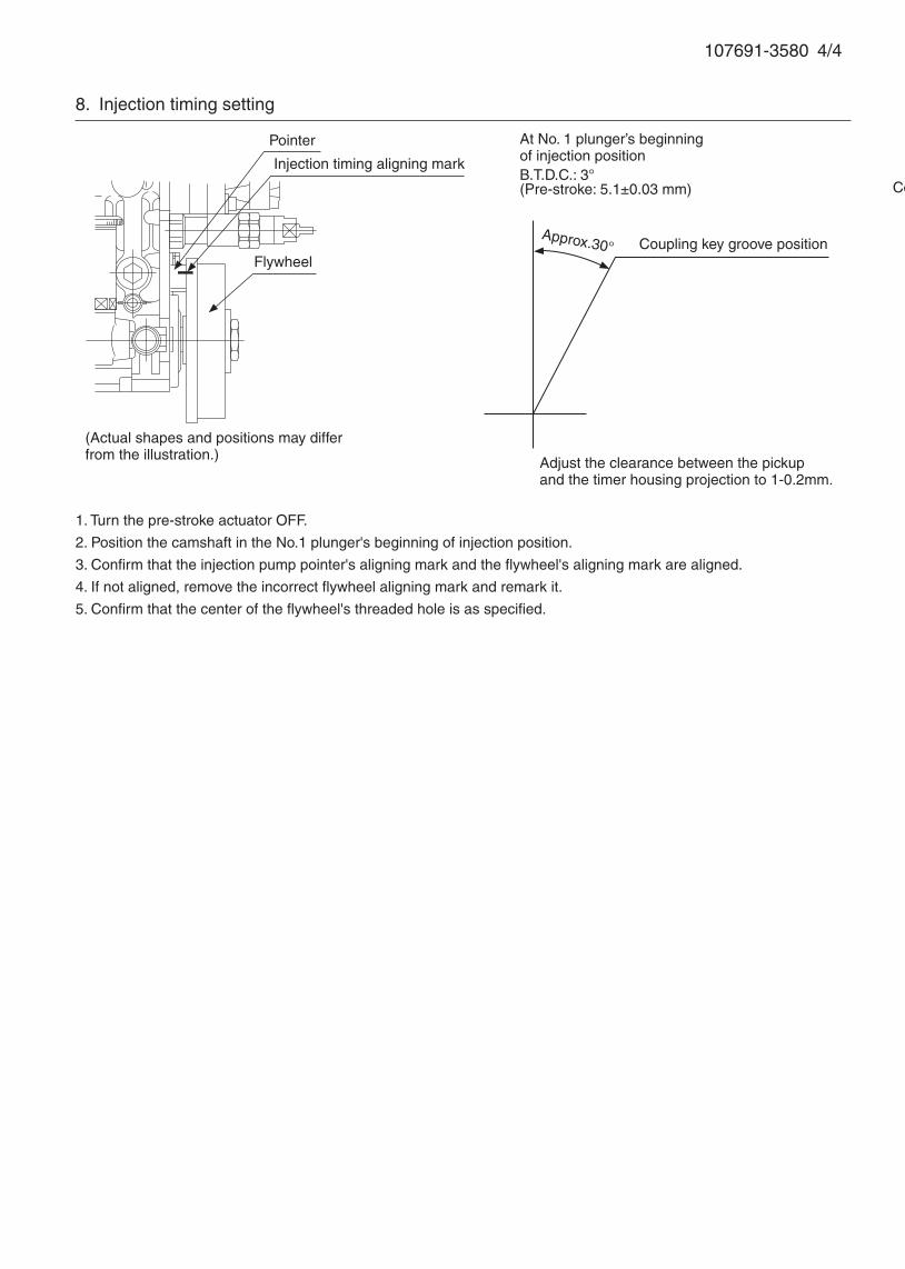
107691-3580 4/4
1. Turn the pre-stroke actuator OFF.
2. Position the camshaft in the No.1 plunger's beginning of injection position.
3. Confirm that the injection pump pointer's aligning mark and the flywheel's aligning mark are aligned.
4. If not aligned, remove the incorrect flywheel aligning mark and remark it.
5. Confirm that the center of the flywheel's threaded hole is as specified.
8. Injection timing setting
At No. 1 plunger’s beginning of injection position
(Pre-stroke: 5.1±0.03 mm)
Injection timing aligning mark
Pointer
Flywheel
(Actual shapes and positions may differfrom the illustration.)
Coupling key groove position
Adjust the clearance between the pickup and the timer housing projection to 1-0.2mm.
B.T.D.C.: 3°
Coupling key groove positionApprox.30°

Pre-stroke(mm)
Pre-stroke sensoroutput voltage (V) Remarks
2.0 ± 0.05 2.83 ± 0.01 Pre-stroke actuator adjustment
5.1 ± 0.03 V1 = 1.2 ± 0.2 Confirmation
- Above 3.05 Confirmation(Pre-stroke actuator operating range)
Note:
1. Adjust using the shim 3.
2. Adjust with the rack in the full-load position.
3. Adjust with the connector 1 contacting the stopper 2.
Injection order:
2. Injection timing
Pre-stroke: No. 1 Plunger 5.1 ± 0.03 mm
Plungers are numbered from the Governor side.
Tappet clearance: Manually rotate the camshaft 2 ~ 3 times and confirm that it rotates smoothly.
Shim 3
DIGI switch No.: 17 (For C/U 407980-224*)
Oil Temp. 40+5 °C
Bosch Automotive Systems Corporation
Service Department
3-4-1 Kitano, Niiza-shi, Saitama-ken, 352-8572 Japan
Tel. (048)470-1559, Fax. (048)474-9856
Company:
Ass'y No.: 107691-3590ENGINE MODEL: J08C-UK
No. Governor: EP/RLD-J
1. Test conditions
Date:
Pump rotation: Counter clockwise ( viewed from drive side )
Injection pump: TC6MD105933-1710
kgf/cm2 }
CONFIDENTIAL
INJECTION PUMP CALIBRATION DATA
29 Nov 2002
22040-2351B
107069-0760
Injection pipe: Outer Dia. 8 mm × Inner Dia. 3 mm Length 600 mm
Nozzle opening pressure: 20.7 MPa { 211 kgf/cm2 }
Nozzle: 105780-0120 Nozzle Holder: 105780-2190(Bosch Type No. 1 688 901 990) (Bosch Type No. )
Nozzle & Nozzle Holder Ass'y: 105780-8250 (Bosch Type No. 1 688 901 101)
Test Oil: ISO4113 or SAE Standard Test Oil { SAE J967d }
2
Transfer pump pressure: 255 kPa { 2.6
1/6
Pre-stroke actuator:159645-4120
3. Pre-stroke actuator adjustment
Pre-stroke actuator type: Retard
Power supply voltage: 24±0.5 V Ambient temperature: 23±5°C
(Timing retard side)
Connector 1
Stopper 2
1 4 , 1 2 , 1 6 , 1 3 , 1 560°± 15' 120°± 15' 180°± 15' 240°± 15' 300°± 15'
HINO
Overflow valve opening pressure: 255 ± 34 kPa { 2.6 ± 0.35 kgf/cm2 }

107691-3590 2/6
Note:
1. Move the pre-stroke actuator fully clockwise (viewed from the drive side), and temporarily secure it to the actuator
housing using the bolts.
Tightening torque: 1.0 ~ 1.5 N•m {0.1 ~ 0.15 kgf•m}
2. Move the pre-stroke actuator counter clockwise (viewed from the drive side) to adjust it.
3. After pre-stroke actuator adjustment, stamp both the pre-stroke actuator and the housing with an aligning mark.
Injection pump
Stamping position
Pre-stroke actuator
Adjustingpoint
PRack
position(mm)
Pumpspeed(r/min)
Injection q'ty(cm3 / 1000 strokes )
Max. variationbetween
cylinders (%)Fixed Remarks
- P1 12.9 750 125 ± 3 ± 3.5 Rack Basic
Z P2 8.2±0.5 440 - Rack Adjust injection q'ty at N = 440.Adjust governor as per gov. adj. spec.
4. Injection quantity variation rate adjustment
P = pre-stroke sensor output at injection quantity adjustment
P1 V = 2.25 ± 0.01 (V) 3.1 ± 0.05 (mm)
P2 V =V1 + 0.05±0.01 (V) 5.0 ± 0.03 (mm)
Each cylinder 13.5±1.35

107691-3590 3/6
If not indicated, the rack position allowance is ± 0.05 mm.
5. Governor adjustment
0190
275350 700
Rac
k po
sitio
n (m
m)
Pump speed (r/min)
10.0
9.7+0.2-0.3
R1(12.9)
R1+0.4
0Below 225 (500) (1320)
A
B
Rac
k po
sitio
n (m
m)
Pump speed (r/min)
Torque cam no. ‘AH29’
R1+2.45
Approx R1+0.4
750
(820)
(1200) (1475)
1520
400
5.1±0.6
8.0Approx 8.2
Full load adjustment
Idling adjustment
Stop lever normal position setting: (18.0)
Boost compensator stroke: 0.95±0.1
12.3±0.1R2[R1-1.15]
9.3±1.0
1585
6.7±0.1
R2[R1-1.15]
R2-0.95
0
38.0±1.3 {285±10}
Approx 50.0 {Approx 375}
N = 300
Rac
k po
sitio
n (m
m)
Boost pressure kPa {mmHg}
Boost compensator adjustment
I
(910)
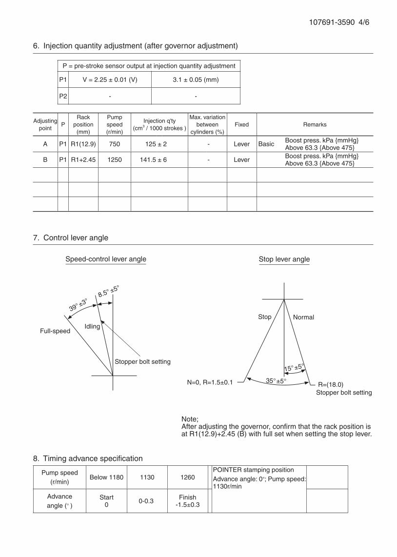
7. Control lever angle
Pump speed(r/min)
Below 1180 1130 1260POINTER stamping positionAdvance angle: 0°; Pump speed: 1130r/min
Advanceangle (° )
Start0 0- 0.3 Finish
-1.5±0.3
8. Timing advance specification
107691-3590 4/6
Adjustingpoint
PRack
position(mm)
Pumpspeed(r/min)
Injection q'ty(cm3 / 1000 strokes )
Max. variationbetween
cylinders (%)Fixed Remarks
A P1 R1(12.9) 750 125 ± 2 - Lever Boost press. kPa {mmHg} Above 63.3 {Above 475}
B P1 R1+2.45 1250 141.5 ± 6 - Lever Boost press. kPa {mmHg} Above 63.3 {Above 475}
6. Injection quantity adjustment (after governor adjustment)
P = pre-stroke sensor output at injection quantity adjustment
P1 V = 2.25 ± 0.01 (V) 3.1 ± 0.05 (mm)
P2 - -
39°±3°
Speed-control lever angle
Idling
Stopper bolt setting
Stop lever angle
N=0, R=1.5±0.1
Stop
Full-speed
Normal
8.5° ±5°
35°±5°
15°±5°
R=(18.0)Stopper bolt setting
Note;After adjusting the governor, confirm that the rack position is at R1(12.9)+2.45 (B) with full set when setting the stop lever.
Basic

107691-3590 5/6
1. Turn the pre-stroke actuator OFF.
2. Position the camshaft in the No.1 plunger's beginning of injection position.
3. Confirm that the injection pump pointer's aligning mark and the flywheel's aligning mark are aligned.
4. If not aligned, remove the incorrect flywheel aligning mark and remark it.
5. Confirm that the center of the flywheel's threaded hole is as specified.
9. Injection timing setting
At No. 1 plunger’s beginning of injection position(Pre-stroke: 5.1±0.03 mm)
Injection timing aligning mark
Pointer
Flywheel
(Actual shapes and positions may differfrom the illustration.)
Coupling key groove positionApprox.30°

107691-3590 6/6
10. Rack sensor adjustment
Amp-equipped rack sensor adjustment (154610-5*20)• Threaded type rack sensor (without rack limit; for P type, TICS)
(1) Screw in bobbin 1 until it contacts the joint 2.
(2) Fix the pump lever at full and screw in the bobbin 1 to adjust the depth so that the amp’s output
voltage V = VR at Np = No and R = Ro. Then, fix the rack sensor using the nut 6.
(3) Move the pump lever 2 or 3 times, reset at full and confirm that the amp’s output voltage V = VR.
(4) Attach the caution plate to the top of the joint 2 and apply red paint to the joint 2 - nut 6 join, and the
pump end face - joint 2 join.
Note:
(1) When adjusting the bobbin 1 and joint 2, the fully tightened position of the bobbin is 9 threads (ie, 9
turns) from where it first engages the joint.
(2) With the welded rack block type, refer to the table below for the R = Ro range (the range varies with
the joint).
Rack sensor power supply 5±0.01V
Speed No 1250 r/min
Rack position Ro R1(12.9) + 2.45 mm
Output voltage VR 3.00±0.01V
Threaded rack block type Welded rack block type
6 1 2
5 4 3
Apply red paint
Pump end face
6 1 2 Apply red paint
Pump end face
4 3
Rack sensor adjusting position
Ro
No Np
Rac
k po
sitio
n Output voltage
VR
Ro
Adjustment Np = No
Joint part no. Ro
154614-2500 10.2 ~ 13.7
154614-4800 5.2 ~ 8.7
154614-8300 15.2 ~ 18.7
154614-8400 20.2 ~ 23.7
154614-8700 7.7 ~ 11.2
154614-8800 12.7 ~ 16.2
154614-8900 17.7 ~ 21.2
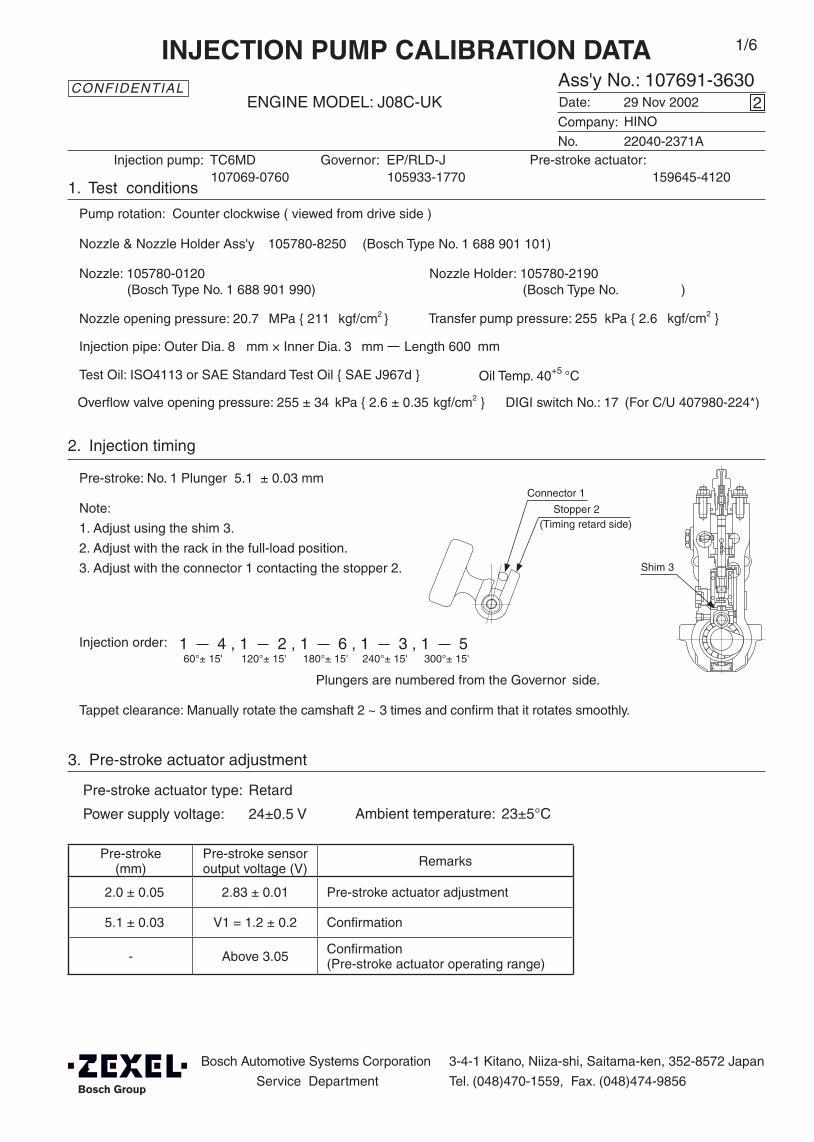
Pre-stroke(mm)
Pre-stroke sensoroutput voltage (V) Remarks
2.0 ± 0.05 2.83 ± 0.01 Pre-stroke actuator adjustment
5.1 ± 0.03 V1 = 1.2 ± 0.2 Confirmation
- Above 3.05 Confirmation(Pre-stroke actuator operating range)
Note:
1. Adjust using the shim 3.
2. Adjust with the rack in the full-load position.
3. Adjust with the connector 1 contacting the stopper 2.
Injection order:
2. Injection timing
Pre-stroke: No. 1 Plunger 5.1 ± 0.03 mm
Plungers are numbered from the Governor side.
Tappet clearance: Manually rotate the camshaft 2 ~ 3 times and confirm that it rotates smoothly.
Shim 3
DIGI switch No.: 17 (For C/U 407980-224*)
Oil Temp. 40+5 °C
Bosch Automotive Systems Corporation
Service Department
3-4-1 Kitano, Niiza-shi, Saitama-ken, 352-8572 Japan
Tel. (048)470-1559, Fax. (048)474-9856
Company:
Ass'y No.: 107691-3630ENGINE MODEL: J08C-UK
No. Governor: EP/RLD-J
1. Test conditions
Date:
Pump rotation: Counter clockwise ( viewed from drive side )
Injection pump: TC6MD105933-1770
kgf/cm2 }
CONFIDENTIAL
INJECTION PUMP CALIBRATION DATA
29 Nov 2002
22040-2371A
107069-0760
Injection pipe: Outer Dia. 8 mm × Inner Dia. 3 mm Length 600 mm
Nozzle opening pressure: 20.7 MPa { 211 kgf/cm2 }
Nozzle: 105780-0120 Nozzle Holder: 105780-2190(Bosch Type No. 1 688 901 990) (Bosch Type No. )
Nozzle & Nozzle Holder Ass'y: 105780-8250 (Bosch Type No. 1 688 901 101)
Test Oil: ISO4113 or SAE Standard Test Oil { SAE J967d }
2
Transfer pump pressure: 255 kPa { 2.6
1/6
Pre-stroke actuator:159645-4120
3. Pre-stroke actuator adjustment
Pre-stroke actuator type: Retard
Power supply voltage: 24±0.5 V Ambient temperature: 23±5°C
(Timing retard side)
Connector 1
Stopper 2
1 4 , 1 2 , 1 6 , 1 3 , 1 560°± 15' 120°± 15' 180°± 15' 240°± 15' 300°± 15'
HINO
Overflow valve opening pressure: 255 ± 34 kPa { 2.6 ± 0.35 kgf/cm2 }
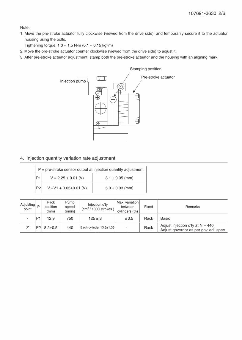
107691-3630 2/6
Note:
1. Move the pre-stroke actuator fully clockwise (viewed from the drive side), and temporarily secure it to the actuator
housing using the bolts.
Tightening torque: 1.0 ~ 1.5 N•m {0.1 ~ 0.15 kgf•m}
2. Move the pre-stroke actuator counter clockwise (viewed from the drive side) to adjust it.
3. After pre-stroke actuator adjustment, stamp both the pre-stroke actuator and the housing with an aligning mark.
Injection pump
Stamping position
Pre-stroke actuator
Adjustingpoint
PRack
position(mm)
Pumpspeed(r/min)
Injection q'ty(cm3 / 1000 strokes )
Max. variationbetween
cylinders (%)Fixed Remarks
- P1 12.9 750 125 ± 3 ± 3.5 Rack Basic
Z P2 8.2±0.5 440 - Rack Adjust injection q'ty at N = 440.Adjust governor as per gov. adj. spec.
4. Injection quantity variation rate adjustment
P = pre-stroke sensor output at injection quantity adjustment
P1 V = 2.25 ± 0.01 (V) 3.1 ± 0.05 (mm)
P2 V =V1 + 0.05±0.01 (V) 5.0 ± 0.03 (mm)
Each cylinder 13.5±1.35
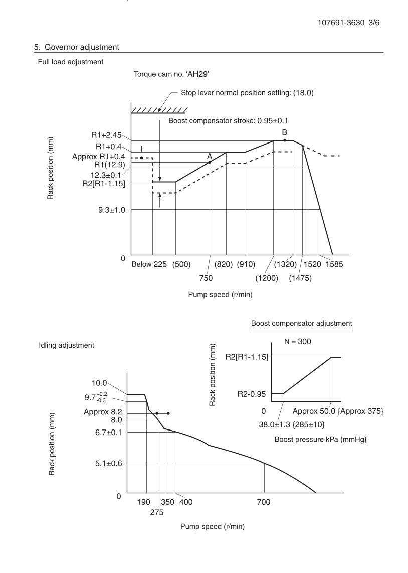
107691-3630 3/6
If not indicated, the rack position allowance is ± 0.05 mm.
5. Governor adjustment
0190
275350 700
Rac
k po
sitio
n (m
m)
Pump speed (r/min)
10.0
9.7+0.2-0.3
R1(12.9)
R1+0.4
0Below 225 (500) (1320)
A
B
Rac
k po
sitio
n (m
m)
Pump speed (r/min)
Torque cam no. ‘AH29’
R1+2.45
Approx R1+0.4
750
(820)
(1200) (1475)
1520
400
5.1±0.6
8.0Approx 8.2
Full load adjustment
Idling adjustment
Stop lever normal position setting: (18.0)
Boost compensator stroke: 0.95±0.1
12.3±0.1R2[R1-1.15]
9.3±1.0
1585
6.7±0.1
R2[R1-1.15]
R2-0.95
0
38.0±1.3 {285±10}
Approx 50.0 {Approx 375}
N = 300
Rac
k po
sitio
n (m
m)
Boost pressure kPa {mmHg}
Boost compensator adjustment
I
(910)

7. Control lever angle
Pump speed(r/min)
Below 1180 1130 1260
Advanceangle (° )
Start0 0- 0.3 Finish
-1.5±0.3
8. Timing advance specification
107691-3630 4/6
Adjustingpoint
PRack
position(mm)
Pumpspeed(r/min)
Injection q'ty(cm3 / 1000 strokes )
Max. variationbetween
cylinders (%)Fixed Remarks
A P1 R1(12.9) 750 125 ± 2 - Lever Boost press. kPa {mmHg} Above 63.3 {Above 475}
B P1 R1+2.45 1250 141.5 ± 6 - Lever Boost press. kPa {mmHg} Above 63.3 {Above 475}
6. Injection quantity adjustment (after governor adjustment)
P = pre-stroke sensor output at injection quantity adjustment
P1 V = 2.25 ± 0.01 (V) 3.1 ± 0.05 (mm)
P2 - -
39°±3°
Speed-control lever angle
Idling
Stopper bolt setting
Stop lever angle
N=0, R=1.5±0.1
Stop
Full-speed
Normal
8.5° ±5°
35°±5°
15°±5°
R=(18.0)Stopper bolt setting
Note;After adjusting the governor, confirm that the rack position is at R1(12.9)+2.45 (B) with full set when setting the stop lever.
POINTER stamping positionAdvance angle: 0°; Pump speed: 1130r/min
Basic

107691-3630 5/6
1. Turn the pre-stroke actuator OFF.
2. Position the camshaft in the No.1 plunger's beginning of injection position.
3. Confirm that the injection pump pointer's aligning mark and the flywheel's aligning mark are aligned.
4. If not aligned, remove the incorrect flywheel aligning mark and remark it.
5. Confirm that the center of the flywheel's threaded hole is as specified.
9. Injection timing setting
At No. 1 plunger’s beginning of injection position(Pre-stroke: 5.1±0.03 mm)
Injection timing aligning mark
Pointer
Flywheel
(Actual shapes and positions may differfrom the illustration.)
Coupling key groove positionApprox.30°

107691-3630 6/6
10. Rack sensor adjustment
Amp-equipped rack sensor adjustment (154610-5*20)• Threaded type rack sensor (without rack limit; for P type, TICS)
(1) Screw in bobbin 1 until it contacts the joint 2.
(2) Fix the pump lever at full and screw in the bobbin 1 to adjust the depth so that the amp’s output
voltage V = VR at Np = No and R = Ro. Then, fix the rack sensor using the nut 6.
(3) Move the pump lever 2 or 3 times, reset at full and confirm that the amp’s output voltage V = VR.
(4) Attach the caution plate to the top of the joint 2 and apply red paint to the joint 2 - nut 6 join, and the
pump end face - joint 2 join.
Note:
(1) When adjusting the bobbin 1 and joint 2, the fully tightened position of the bobbin is 9 threads (ie, 9
turns) from where it first engages the joint.
(2) With the welded rack block type, refer to the table below for the R = Ro range (the range varies with
the joint).
Rack sensor power supply 5±0.01V
Speed No 1250 r/min
Rack position Ro R1(12.9) + 2.45 mm
Output voltage VR 3.00±0.01V
Threaded rack block type Welded rack block type
6 1 2
5 4 3
Apply red paint
Pump end face
6 1 2 Apply red paint
Pump end face
4 3
Rack sensor adjusting position
Ro
No Np
Rac
k po
sitio
n Output voltage
VR
Ro
Adjustment Np = No
Joint part no. Ro
154614-2500 10.2 ~ 13.7
154614-4800 5.2 ~ 8.7
154614-8300 15.2 ~ 18.7
154614-8400 20.2 ~ 23.7
154614-8700 7.7 ~ 11.2
154614-8800 12.7 ~ 16.2
154614-8900 17.7 ~ 21.2

Pre-stroke(mm)
Pre-stroke sensoroutput voltage (V) Remarks
2.0 ± 0.05 2.83 ± 0.01 Pre-stroke actuator adjustment
5.1 ± 0.03 V1 = 1.2 ± 0.2 Confirmation
- Above 3.05 Confirmation(Pre-stroke actuator operating range)
Note:
1. Adjust using the shim 3.
2. Adjust with the rack in the full-load position.
3. Adjust with the connector 1 contacting the stopper 2.
Injection order:
2. Injection timing
Pre-stroke: No. 1 Plunger 5.1 ± 0.03 mm
Plungers are numbered from the Governor side.
Tappet clearance: Manually rotate the camshaft 2 ~ 3 times and confirm that it rotates smoothly.
Shim 3
DIGI switch No.: 17 (For C/U 407980-224*)
Oil Temp. 40+5 °C
Bosch Automotive Systems Corporation
Service Department
3-4-1 Kitano, Niiza-shi, Saitama-ken, 352-8572 Japan
Tel. (048)470-1559, Fax. (048)474-9856
Company:
Ass'y No.: 107691-3690ENGINE MODEL: J08C-UL
No. Governor: EP/RLD-J
1. Test conditions
Date:
Pump rotation: Counter clockwise ( viewed from drive side )
Injection pump: TC6MD105933-1830
kgf/cm2 }
CONFIDENTIAL
INJECTION PUMP CALIBRATION DATA
10 Feb 2003
22040-2320B
107069-0740
Injection pipe: Outer Dia. 8 mm × Inner Dia. 3 mm Length 600 mm
Nozzle opening pressure: 20.7 MPa { 211 kgf/cm2 }
Nozzle: 105780-0120 Nozzle Holder: 105780-2190(Bosch Type No. 1 688 901 990) (Bosch Type No. )
Nozzle & Nozzle Holder Ass'y: 105780-8250 (Bosch Type No. 1 688 901 101)
Test Oil: ISO4113 or SAE Standard Test Oil { SAE J967d }
1
Transfer pump pressure: 255 kPa { 2.6
1/6
Pre-stroke actuator:159645-4120
3. Pre-stroke actuator adjustment
Pre-stroke actuator type: Retard
Power supply voltage: 24±0.5 V Ambient temperature: 23±5°C
(Timing retard side)
Connector 1
Stopper 2
1 4 , 1 2 , 1 6 , 1 3 , 1 560°± 15' 120°± 15' 180°± 15' 240°± 15' 300°± 15'
HINO
Overflow valve opening pressure: 255 ± 34 kPa { 2.6 ± 0.35 kgf/cm2 }
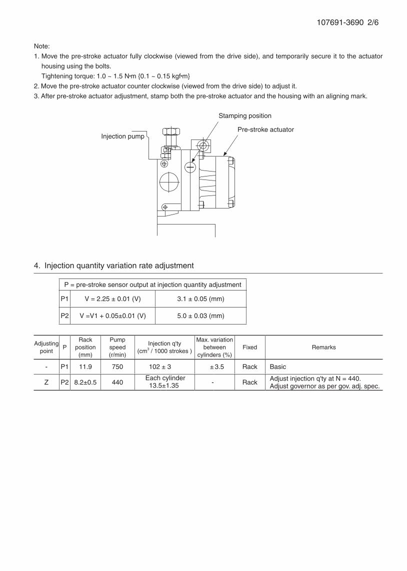
107691-3690 2/6
Note:
1. Move the pre-stroke actuator fully clockwise (viewed from the drive side), and temporarily secure it to the actuator
housing using the bolts.
Tightening torque: 1.0 ~ 1.5 N•m {0.1 ~ 0.15 kgf•m}
2. Move the pre-stroke actuator counter clockwise (viewed from the drive side) to adjust it.
3. After pre-stroke actuator adjustment, stamp both the pre-stroke actuator and the housing with an aligning mark.
Injection pump
Stamping position
Pre-stroke actuator
Adjustingpoint
PRack
position(mm)
Pumpspeed(r/min)
Injection q'ty(cm3 / 1000 strokes )
Max. variationbetween
cylinders (%)Fixed Remarks
- P1 11.9 750 102 ± 3 ± 3.5 Rack Basic
Z P2 8.2±0.5 440 - Rack Adjust injection q'ty at N = 440.Adjust governor as per gov. adj. spec.
4. Injection quantity variation rate adjustment
P = pre-stroke sensor output at injection quantity adjustment
P1 V = 2.25 ± 0.01 (V) 3.1 ± 0.05 (mm)
P2 V =V1 + 0.05±0.01 (V) 5.0 ± 0.03 (mm)
Each cylinder 13.5±1.35
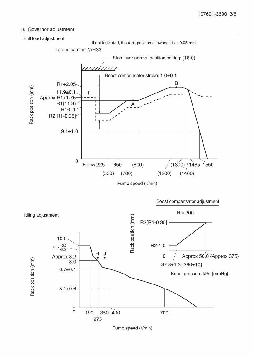
107691-3690 3/6
3. Governor adjustment
0190
275350 700
Rac
k po
sitio
n (m
m)
Pump speed (r/min)
10.0
9.7+0.2-0.3
R1(11.9)Approx R1+1.75
0Below 225 650 (1300)
A
B
Rac
k po
sitio
n (m
m)
Pump speed (r/min)
Torque cam no. ‘AH33’
R1+2.05
(700)
(800)
(1200) (1460)
1485
400
5.1±0.6
8.0Approx 8.2
Full load adjustment
Idling adjustment
Stop lever normal position setting: (18.0)
Boost compensator stroke: 1.0±0.1
R1-0.1R2[R1-0.35]
9.1±1.0
1550
6.7±0.1
R2[R1-0.35]
R2-1.0
0
37.3±1.3 {280±10}
Approx 50.0 {Approx 375}
N = 300
Rac
k po
sitio
n (m
m)
Boost pressure kPa {mmHg}
Boost compensator adjustment
11.9±0.1
(530)
I
H J
If not indicated, the rack position allowance is ± 0.05 mm.

7. Control lever angle
Pump speed(r/min)
Below 1150 1100 1250-50
Advanceangle (° )
Start0 0 -0.3 Finish
-1.5±0.3
8. Timing advance specification
107691-3690 4/6
Adjustingpoint
PRack
position(mm)
Pumpspeed(r/min)
Injection q'ty(cm3 / 1000 strokes )
Max. variationbetween
cylinders (%)Fixed Remarks
A P1 R1(11.9) 750 102 ± 2 - Lever Boost press. kPa {mmHg} Above 63.3 {Above 475}
B P1 R1+2.05 1250 114 ± 6 - Lever Boost press. kPa {mmHg} Above 63.3 {Above 475}
6. Injection quantity adjustment (after governor adjustment)
P = pre-stroke sensor output at injection quantity adjustment
P1 V = 2.25 ± 0.01 (V) 3.1 ± 0.05 (mm)
P2 - -
35.5° ±3°
Speed-control lever angle
Idling
Stop lever angle
N=0, R=1.5±0.1
Stop
Full-speed
Normal
8.5°±5°
35°±5°
15°±5°
R=(18.0)Stopper bolt setting
Note;After adjusting the governor, confirm that the rack position is at R1(11.9)+2.05 (B) with full set when setting the stop lever.
Basic
Stopper bolt H position

107691-3690 5/6
1. Turn the pre-stroke actuator OFF.
2. Position the camshaft in the No.1 plunger's beginning of injection position.
3. Confirm that the injection pump pointer's aligning mark and the flywheel's aligning mark are aligned.
4. If not aligned, remove the incorrect flywheel aligning mark and remark it.
5. Confirm that the center of the flywheel's threaded hole is as specified.
9. Injection timing setting
At No. 1 plunger’s beginning of injection position(Pre-stroke: 5.1±0.03 mm)
Injection timing aligning mark
Pointer
Flywheel
(Actual shapes and positions may differfrom the illustration.)
Coupling key groove positionApprox.30°

107691-3690 6/6
10. Rack sensor adjustment
Amp-equipped rack sensor adjustment (154610-5*20)• Threaded type rack sensor (without rack limit; for P type, TICS)
(1) Screw in bobbin 1 until it contacts the joint 2.
(2) Fix the pump lever at full and screw in the bobbin 1 to adjust the depth so that the amp’s output
voltage V = VR at Np = No and R = Ro. Then, fix the rack sensor using the nut 6.
(3) Move the pump lever 2 or 3 times, reset at full and confirm that the amp’s output voltage V = VR.
(4) Attach the caution plate to the top of the joint 2 and apply red paint to the joint 2 - nut 6 join, and the
pump end face - joint 2 join.
Note:
(1) When adjusting the bobbin 1 and joint 2, the fully tightened position of the bobbin is 9 threads (ie, 9
turns) from where it first engages the joint.
(2) With the welded rack block type, refer to the table below for the R = Ro range (the range varies with
the joint).
Rack sensor power supply 5±0.01V
Speed No 1250 r/min
Rack position Ro R1(11.9) + 2.05 mm
Output voltage VR 3.00±0.01V
Threaded rack block type Welded rack block type
6 1 2
5 4 3
Apply red paint
Pump end face
6 1 2 Apply red paint
Pump end face
4 3
Rack sensor adjusting position
Ro
No Np
Rac
k po
sitio
n Output voltage
VR
Ro
Adjustment Np = No
Joint part no. Ro
154614-2500 10.2 ~ 13.7
154614-4800 5.2 ~ 8.7
154614-8300 15.2 ~ 18.7
154614-8400 20.2 ~ 23.7
154614-8700 7.7 ~ 11.2
154614-8800 12.7 ~ 16.2
154614-8900 17.7 ~ 21.2
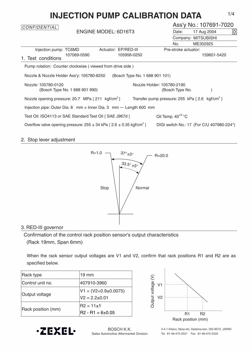
Actuator: EP/RED-III 105956-0250
DIGI switch No.: 17 (For C/U 407980-224*)
Oil Temp. 40+5 °C
Company:
Ass'y No.: 107691-7020ENGINE MODEL: 6D16T3
No.
1. Test conditions
Date:
Pump rotation: Counter clockwise ( viewed from drive side )
Injection pump: TC6MD
kgf/cm2 }
CONFIDENTIAL
INJECTION PUMP CALIBRATION DATA
17 Aug 2004
ME302925
107069-0590
Injection pipe: Outer Dia. 8 mm × Inner Dia. 3 mm Length 600 mm
Nozzle opening pressure: 20.7 MPa { 211 kgf/cm2 }
Nozzle: 105780-0120 Nozzle Holder: 105780-2190(Bosch Type No. 1 688 901 990) (Bosch Type No. )
Nozzle & Nozzle Holder Ass'y: 105780-8250 (Bosch Type No. 1 688 901 101)
Overflow valve opening pressure: 255 ± 34 kPa { 2.6 ± 0.35 kgf/cm2 }
Test Oil: ISO4113 or SAE Standard Test Oil { SAE J967d }
0
Transfer pump pressure: 255 kPa { 2.6
1/4
Pre-stroke actuator:159601-5420
MITSUBISHI
2. Stop lever adjustment
3. RED-III governor
Confirmation of the control rack position sensor's output characteristics
(Rack 19mm, Span 6mm)
When the rack sensor output voltages are V1 and V2, confirm that rack positions R1 and R2 are as
specified below.
Rack type 19 mm
Control unit no. 407910-3960
Output voltageV1 = (V2+0.9±0.0075)
V2 = 2.2±0.01
Rack position (mm)R2 = 11±1
R2 - R1 = 6±0.05
Rack position (mm)R1 R2
Out
put v
olta
ge (
V)
V1
V2
37°±5° R=20.0
Stop Normal
33.5° ±5°
R=1.0
BOSCH K.K.Sales Automotive Aftermarket Division
3-4-1 Kitano, Niiza-shi, Saitama-ken, 352-8572, JAPAN
Tel. 81-48-475-2521 Fax. 81-48-475-2520

107691-7020 2/4
Pre-stroke(mm)
Pre-stroke sensoroutput voltage (V) Remarks
2.0 ± 0.05 2.83 ± 0.01 Pre-stroke actuator adjustment
5.1 ± 0.03 V1 = 1.2 ± 0.2 Confirmation
- Above 3.05 Confirmation(Pre-stroke actuator operating range)
Note:
1. Adjust using the shim 3.
2. Adjust with the rack in the full-load position.
3. Adjust with the connector 1 contacting the stopper 2.
Injection order:
4. Injection timing
Pre-stroke: No. 1 Plunger 5.1 ± 0.03 mm
Plungers are numbered from the Governor side.
Tappet clearance: Manually rotate the camshaft 2 ~ 3 times and confirm that it rotates smoothly.
Shim 3
5. Pre-stroke actuator adjustment
Pre-stroke actuator type: Retard
Power supply voltage: 24±0.5 V Ambient temperature: 23±5°C
(Timing retard side)
Connector 1
Stopper 2
1 5 , 1 3 , 1 6 , 1 2 , 1 460°± 15' 120°± 15' 180°± 15' 240°± 15' 300°± 15'
Note:
1. Move the pre-stroke actuator fully clockwise (viewed from the drive side), and temporarily secure it to the actuator housing using the bolts.Tightening torque: 1.0 ~ 1.5 N•m {0.1 ~ 0.15 kgf•m}
2. Move the pre-stroke actuator Counter clockwise (viewed from the drive side) to adjust it.
3. After pre-stroke actuator adjustment, stamp both the pre-stroke actuator and the housing with an aligning mark.
Stamping position
Pre-stroke actuatorInjection pump

107691-7020 3/4
6. Injection quantity
P = pre-stroke sensor output at injection quantity adjustment
P1 V = 2.25 ± 0.01 (V) 3.1 ± 0.05 (mm)
P2 V = V1 + 0.05 ± 0.01 (V) 5.0 ± 0.03 (mm)
PRack
position(mm)
Vist(V)
Pumpspeed(r/min)
Injection q'ty(cm3 / 1000 strokes )
Max. variationbetween
cylinders (%)Remarks
P1 (12.5) 1.98 800 140 ± 1 ± 3 Basic
P2 (6.6) 2.9 ± 0.1 395 16.5 ± 1.8 ± 15
Pump speed(r/min)
Below1050 1000 1075
Advanceangle (° )
Start0 0 - 0.5 Finish
-1.5±0.5
8. Timing advance specification
1. Turn the pre-stroke actuator OFF.
2. Position the camshaft in the No.1 plunger's beginning of injection position.
3. Confirm that the injection pump pointer's aligning mark and the flywheel's aligning mark are aligned.
4. If not aligned, remove the incorrect flywheel aligning mark and remark it.
5. Confirm that the center of the flywheel's threaded hole is as specified.
9. Injection timing setting
At No. 1 plunger’s beginning of injection position(Pre-stroke: 5.1±0.03 mm)
Injection timing aligning mark
Pointer
Flywheel
(Actual shapes and positions may differfrom the illustration.)
Coupling key groove positionApprox.2°
Adjust the clearance between the pickup and the gear tooth to 1-0.2mm.
B.T.D.C.: 2°

107691-7020 4/4
7. Drive side rack sensor adjustment (-0620)• Threaded type rack sensor (For REDIII governor)
(1) Screw in bobbin 1 until it contacts the joint 2.
(2) When the governor side rack sensor output is VG, adjust the depth that the bobbin 1 is screwed in so
that the drive side rack sensor output voltage is VR±0.01V. Then, fix using the nut 5.
5
4 3
Pump end face
Apply red paint21
Rack sensor power supply 5±0.01V
Governor side rack sensor output VG 1.60V
Drive side rack sensor output voltage VR±0.01V
(3) Reset the governor side rack sensor output at VG and confirm that the drive side rack sensor output
voltage is VR±0.01V.
(4) Attach the caution plate to the top of the joint 2 and apply red paint to the joint 2 and nut 5 join and to
the pump end face and joint 2 join.
Note:
When adjusting the depth that the bobbin 1 is screwed into the joint 2, the fully tightened position of the
bobbin is 9 threads (ie, 9 turns) from where it first engages the threads.
VR Control unit part no.
2V407912-1742
105782-6320
3V
407910-3032
407910-6010
407910-7210
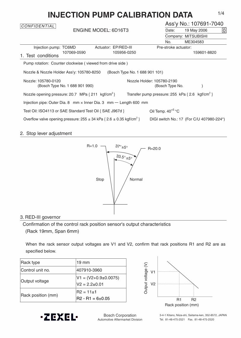
Actuator: EP/RED-III 105956-0250
DIGI switch No.: 17 (For C/U 407980-224*)
Oil Temp. 40+5 °C
Company:
Ass'y No.: 107691-7040ENGINE MODEL: 6D16T3
No.
1. Test conditions
Date:
Pump rotation: Counter clockwise ( viewed from drive side )
Injection pump: TC6MD
kgf/cm2 }
CONFIDENTIAL
INJECTION PUMP CALIBRATION DATA
19 May 2006
ME304583
107069-0590
Injection pipe: Outer Dia. 8 mm × Inner Dia. 3 mm Length 600 mm
Nozzle opening pressure: 20.7 MPa { 211 kgf/cm2 }
Nozzle: 105780-0120 Nozzle Holder: 105780-2190(Bosch Type No. 1 688 901 990) (Bosch Type No. )
Nozzle & Nozzle Holder Ass'y: 105780-8250 (Bosch Type No. 1 688 901 101)
Overflow valve opening pressure: 255 ± 34 kPa { 2.6 ± 0.35 kgf/cm2 }
Test Oil: ISO4113 or SAE Standard Test Oil { SAE J967d }
0
Transfer pump pressure: 255 kPa { 2.6
1/4
Pre-stroke actuator:159601-8820
MITSUBISHI
2. Stop lever adjustment
3. RED-III governor
Confirmation of the control rack position sensor's output characteristics
(Rack 19mm, Span 6mm)
When the rack sensor output voltages are V1 and V2, confirm that rack positions R1 and R2 are as
specified below.
Rack type 19 mm
Control unit no. 407910-3960
Output voltageV1 = (V2+0.9±0.0075)
V2 = 2.2±0.01
Rack position (mm)R2 = 11±1
R2 - R1 = 6±0.05
Rack position (mm)R1 R2
Out
put v
olta
ge (
V)
V1
V2
37°±5° R=20.0
Stop Normal
33.5° ±5°
R=1.0
Bosch CorporationAutomotive Aftermarket Division
3-4-1 Kitano, Niiza-shi, Saitama-ken, 352-8572, JAPAN
Tel. 81-48-475-2521 Fax. 81-48-475-2520
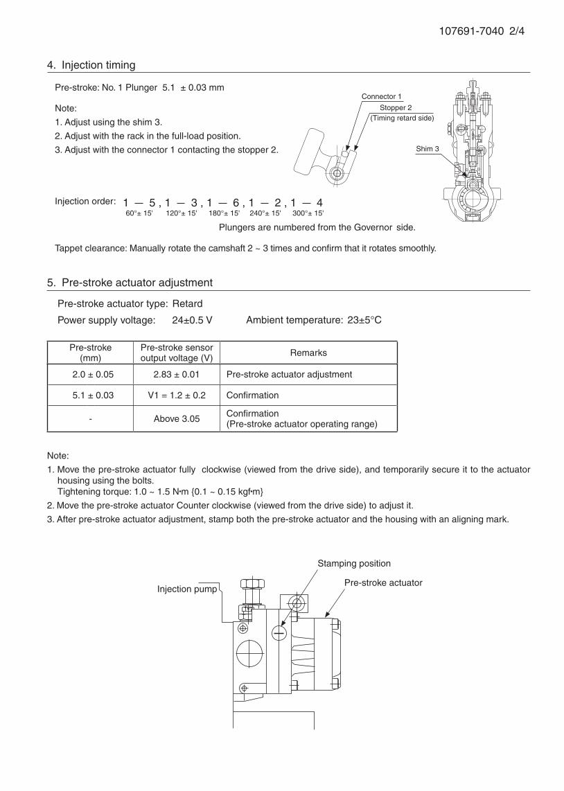
107691-7040 2/4
Pre-stroke(mm)
Pre-stroke sensoroutput voltage (V) Remarks
2.0 ± 0.05 2.83 ± 0.01 Pre-stroke actuator adjustment
5.1 ± 0.03 V1 = 1.2 ± 0.2 Confirmation
- Above 3.05 Confirmation(Pre-stroke actuator operating range)
Note:
1. Adjust using the shim 3.
2. Adjust with the rack in the full-load position.
3. Adjust with the connector 1 contacting the stopper 2.
Injection order:
4. Injection timing
Pre-stroke: No. 1 Plunger 5.1 ± 0.03 mm
Plungers are numbered from the Governor side.
Tappet clearance: Manually rotate the camshaft 2 ~ 3 times and confirm that it rotates smoothly.
Shim 3
5. Pre-stroke actuator adjustment
Pre-stroke actuator type: Retard
Power supply voltage: 24±0.5 V Ambient temperature: 23±5°C
(Timing retard side)
Connector 1
Stopper 2
1 5 , 1 3 , 1 6 , 1 2 , 1 460°± 15' 120°± 15' 180°± 15' 240°± 15' 300°± 15'
Note:
1. Move the pre-stroke actuator fully clockwise (viewed from the drive side), and temporarily secure it to the actuator housing using the bolts.Tightening torque: 1.0 ~ 1.5 N•m {0.1 ~ 0.15 kgf•m}
2. Move the pre-stroke actuator Counter clockwise (viewed from the drive side) to adjust it.
3. After pre-stroke actuator adjustment, stamp both the pre-stroke actuator and the housing with an aligning mark.
Stamping position
Pre-stroke actuatorInjection pump
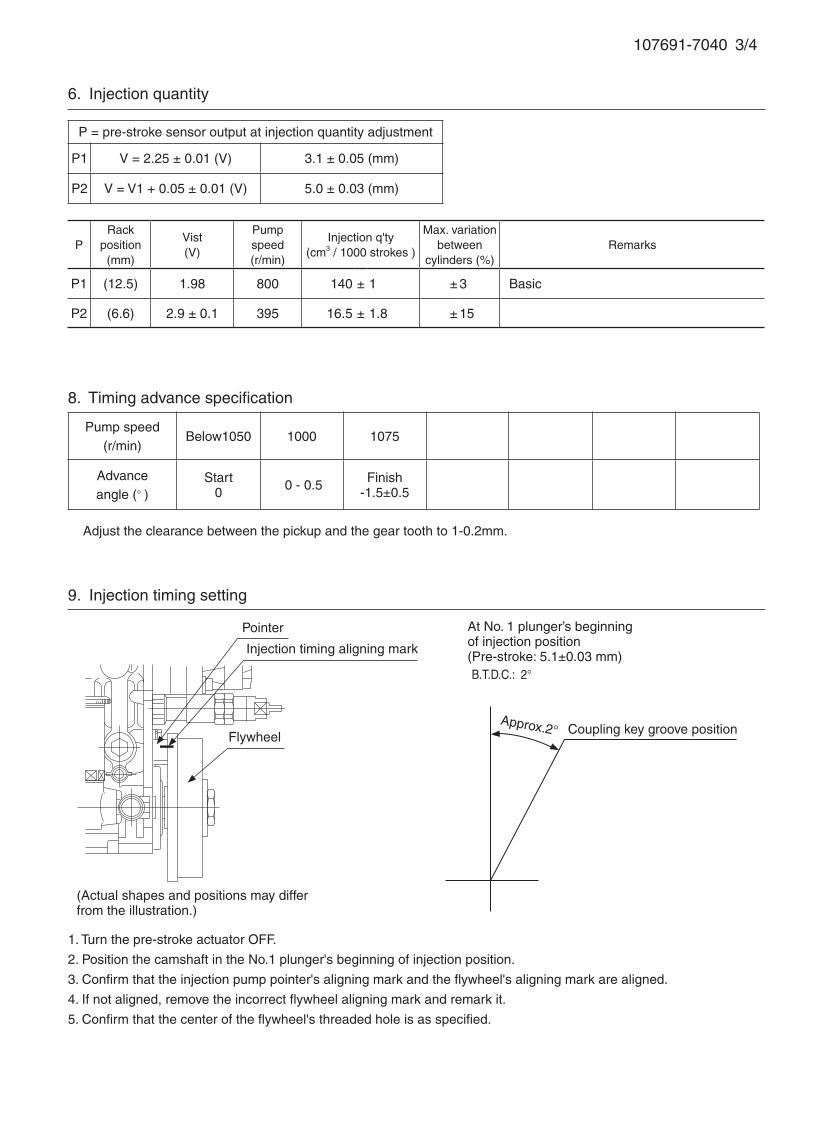
107691-7040 3/4
6. Injection quantity
P = pre-stroke sensor output at injection quantity adjustment
P1 V = 2.25 ± 0.01 (V) 3.1 ± 0.05 (mm)
P2 V = V1 + 0.05 ± 0.01 (V) 5.0 ± 0.03 (mm)
PRack
position(mm)
Vist(V)
Pumpspeed(r/min)
Injection q'ty(cm3 / 1000 strokes )
Max. variationbetween
cylinders (%)Remarks
P1 (12.5) 1.98 800 140 ± 1 ± 3 Basic
P2 (6.6) 2.9 ± 0.1 395 16.5 ± 1.8 ± 15
Pump speed(r/min)
Below1050 1000 1075
Advanceangle (° )
Start0 0 - 0.5 Finish
-1.5±0.5
8. Timing advance specification
1. Turn the pre-stroke actuator OFF.
2. Position the camshaft in the No.1 plunger's beginning of injection position.
3. Confirm that the injection pump pointer's aligning mark and the flywheel's aligning mark are aligned.
4. If not aligned, remove the incorrect flywheel aligning mark and remark it.
5. Confirm that the center of the flywheel's threaded hole is as specified.
9. Injection timing setting
At No. 1 plunger’s beginning of injection position(Pre-stroke: 5.1±0.03 mm)
Injection timing aligning mark
Pointer
Flywheel
(Actual shapes and positions may differfrom the illustration.)
Coupling key groove positionApprox.2°
Adjust the clearance between the pickup and the gear tooth to 1-0.2mm.
B.T.D.C.: 2°
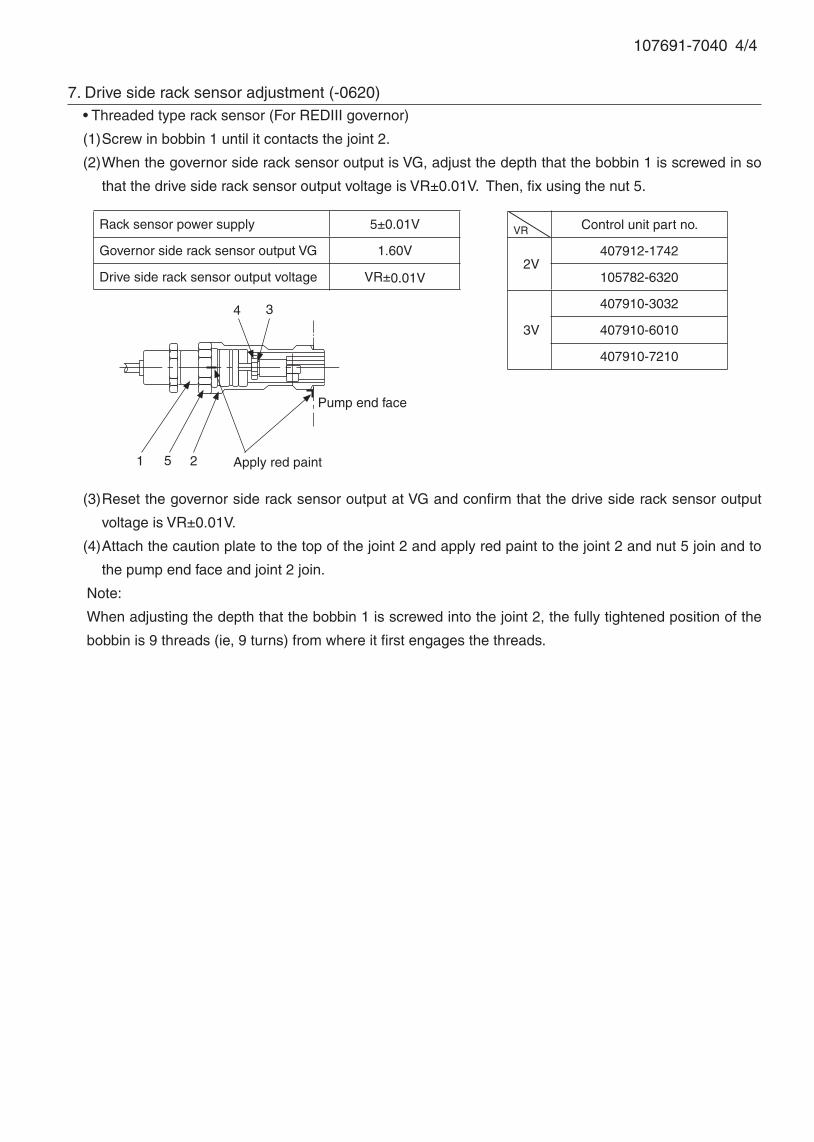
107691-7040 4/4
7. Drive side rack sensor adjustment (-0620)• Threaded type rack sensor (For REDIII governor)
(1) Screw in bobbin 1 until it contacts the joint 2.
(2) When the governor side rack sensor output is VG, adjust the depth that the bobbin 1 is screwed in so
that the drive side rack sensor output voltage is VR±0.01V. Then, fix using the nut 5.
5
4 3
Pump end face
Apply red paint21
Rack sensor power supply 5±0.01V
Governor side rack sensor output VG 1.60V
Drive side rack sensor output voltage VR±0.01V
(3) Reset the governor side rack sensor output at VG and confirm that the drive side rack sensor output
voltage is VR±0.01V.
(4) Attach the caution plate to the top of the joint 2 and apply red paint to the joint 2 and nut 5 join and to
the pump end face and joint 2 join.
Note:
When adjusting the depth that the bobbin 1 is screwed into the joint 2, the fully tightened position of the
bobbin is 9 threads (ie, 9 turns) from where it first engages the threads.
VR Control unit part no.
2V407912-1742
105782-6320
3V
407910-3032
407910-6010
407910-7210

DIGI switch no.: 17 (for C/U 407980-224*)
Oil temperature: 40+5 °C
BOSCH K.K.Sales Automotive Aftermarket Division
3-4-1 Kitano, Niiza-shi, Saitama-ken, 352-8572, JAPAN
Tel. 81-48-475-2521 Fax. 81-48-475-2520
Pre-stroke(mm)
Pre-stroke sensoroutput voltage (V) Remarks
2.5 ± 0.05 2.83 ± 0.01 Pre-stroke actuator adjustment
5.6 ± 0.03 V1 = 1.2 ± 0.2 Confirmation
- Above 3.05 Confirmation(Pre-stroke actuator operating range)
Note:
1. Adjust using the shim 3.
2. Adjust with the rack in the full-load position.
3. Adjust with the connector 1 contacting the stopper 2.
Injection order:
2. Injection timing
Pre-stroke: No. 1 plunger 5.6 ± 0.03 mm
Plungers are numbered from the Governor side.
1 5 , 1 3 , 1 6 , 1 2 , 1 460°± 15' 120°± 15' 180°± 15' 240°± 15' 300°± 15'
Tappet clearance: Manually rotate the camshaft 2 ~ 3 times and confirm that it rotates smoothly.
Shim 3
Company:
Assy No.: 107692-2086ENGINE MODEL: 6D16T5
No. Governor: EP/RLD-J
1. Test conditions
Date:
Pump rotation: Countor clockwise (viewed from drive side)
Injection pump: TC6MD105933-0252
kgf/cm2}
CONFIDENTIAL
INJECTION PUMP CALIBRATION DATA
10 Apr 2006
MITSUBISHI
ME075629
107069-0120
Injection pipe: outer dia. 8 mm × inner dia. 3 mm length 600 mm
Nozzle opening pressure: 20.7 MPa {211 kgf/cm2}
Nozzle: 105780-0120 Nozzle holder: 105780-2190(Bosch type no. 1 688 901 990) (Bosch type no. )
Nozzle & nozzle holder assy: 105780-8250 (Bosch type no. 1 688 901 101)
Test oil: ISO4113 or SAE standard test oil {SAE J967d}
8
Transfer pump pressure: 255 kPa {2.6
1/6
Pre-stroke actuator:159600-2620
3. Pre-stroke actuator adjustment
Pre-stroke actuator type: Retard
Power supply voltage: 24±0.5 V Ambient temperature: 23±5°C
(Timing retard side)
Connector 1
Stopper 2
Overflow valve opening pressure: 255 ± 34 kPa {2.6 ± 0.35 kgf/cm2}

107692-2086 2/6
Note:
1. Move the pre-stroke actuator fully clockwise (viewed from the drive side), and temporarily secure it to the actuator
housing using the bolts.
Tightening torque: 1.0 ~ 1.5 N•m {0.1 ~ 0.15 kgf•m}
2. Move the pre-stroke actuator counterclockwise (viewed from the drive side) to adjust it.
3. After pre-stroke actuator adjustment, stamp both the pre-stroke actuator and the housing with an aligning mark.
Injection pump
Stamping position
Pre-stroke actuator
Adjustingpoint
PRack
position(mm)
Pumpspeed(r/min)
Injection quantity(cm3/1000 strokes)
Max. variationbetween
cylinders (%)Fixed Remarks
- P1 13.4 700 122 ± 2 ± 3 Rack Basic Cylinder variation adjustment standard
Z P2 Approx7.7 510 10.5 ± 1.8 ± 15 Rack Cylinder variation adjustment standard
4. Injection quantity variation rate adjustment
P = pre-stroke sensor output at injection quantity adjustment
P1 V = 2.25 ± 0.01 (V) 3.6 ± 0.05 (mm)
P2 V = V1 + 0.05 ± 0.01 (V) 5.5 ± 0.03 (mm)
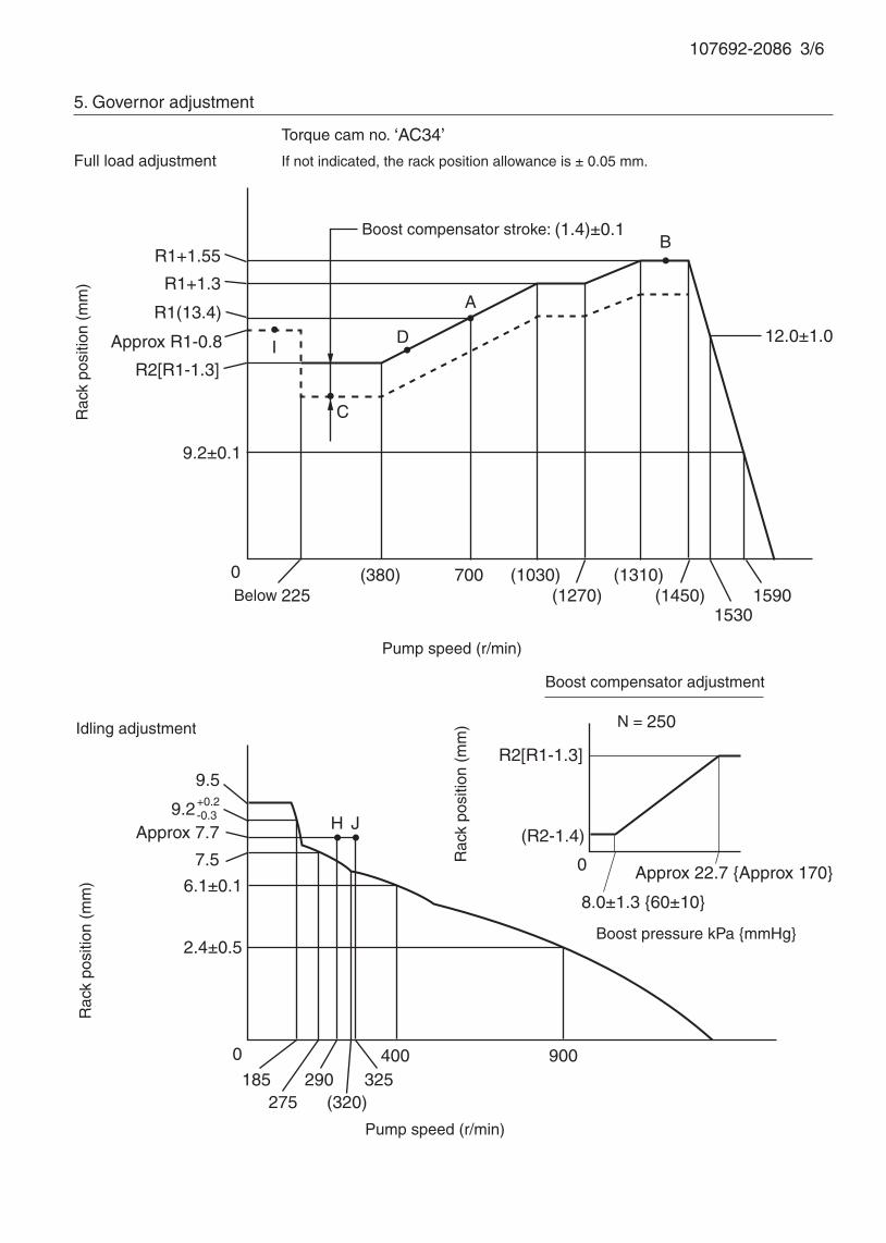
107692-2086 3/6
5. Governor adjustment
If not indicated, the rack position allowance is ± 0.05 mm.Full load adjustment
Idling adjustment
Torque cam no. ‘AC34’
Boost compensator stroke: (1.4)±0.1
Rac
k po
sitio
n (m
m)
Pump speed (r/min)
Rac
k po
sitio
n (m
m)
Pump speed (r/min)
R2[R1-1.3]
(R2-1.4)
0
8.0±1.3 {60±10}
Approx 22.7 {Approx 170}
N = 250
Rac
k po
sitio
n (m
m)
Boost pressure kPa {mmHg}
Boost compensator adjustment
0
185275
290900
9.5
9.2+0.2-0.3
325
2.4±0.5
7.5
Approx 7.7
6.1±0.1
R1(13.4)
R1+1.3
0Below 225
(1310)
A
BR1+1.55
Approx R1-0.8
700(1270) (1450)
1530
R2[R1-1.3]
9.2±0.1
1590
I
(1030)(380)
D
C
12.0±1.0
(320)
400
H J
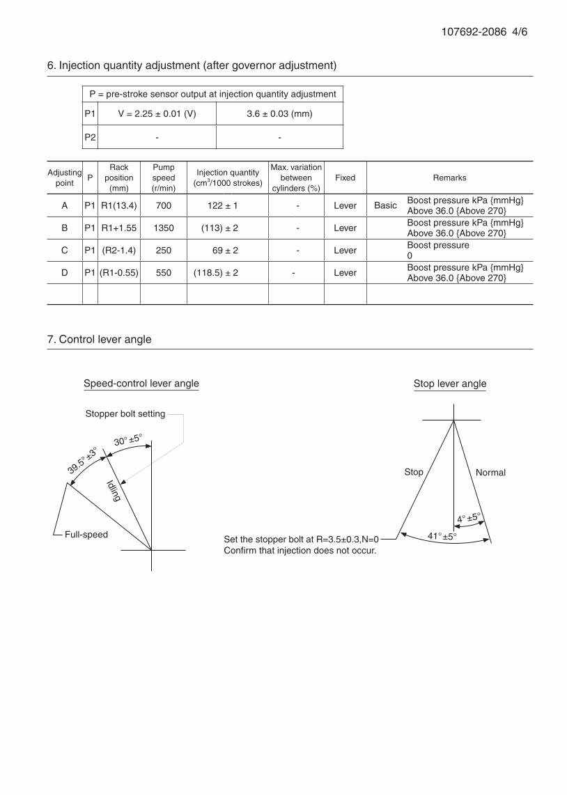
7. Control lever angle
107692-2086 4/6
Adjustingpoint
PRack
position(mm)
Pumpspeed(r/min)
Injection quantity(cm3/1000 strokes)
Max. variationbetween
cylinders (%)Fixed Remarks
A P1 R1(13.4) 700 122 ± 1 - Lever Boost pressure kPa {mmHg} Above 36.0 {Above 270}
B P1 R1+1.55 1350 (113) ± 2 - Lever Boost pressure kPa {mmHg} Above 36.0 {Above 270}
C P1 (R2-1.4) 250 69 ± 2 - Lever Boost pressure 0
D P1 (R1-0.55) 550 (118.5) ± 2 - Lever Boost pressure kPa {mmHg} Above 36.0 {Above 270}
6. Injection quantity adjustment (after governor adjustment)
P = pre-stroke sensor output at injection quantity adjustment
P1 V = 2.25 ± 0.01 (V) 3.6 ± 0.03 (mm)
P2 - -
Basic
39.5°±
3°
Speed-control lever angle
Idling
Stopper bolt setting
Stop lever angle
Stop
Full-speed
Normal
30°±5°
41°±5°
4°±5°
Set the stopper bolt at R=3.5±0.3,N=0 Confirm that injection does not occur.
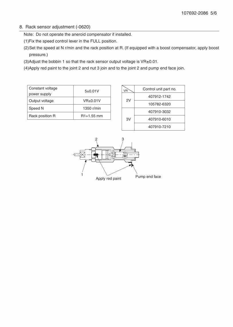
107692-2086 5/6
8. Rack sensor adjustment (-0620)
Note: Do not operate the aneroid compensator if installed.
(1)Fix the speed control lever in the FULL position.
(2) Set the speed at N r/min and the rack position at R. (If equipped with a boost compensator, apply boost
pressure.)
(3)Adjust the bobbin 1 so that the rack sensor output voltage is VR±0.01.
(4)Apply red paint to the joint 2 and nut 3 join and to the joint 2 and pump end face join.
1
2 3
Constant voltage
power supply5±0.01V
Output voltage VR±0.01V
Speed N 1350 r/min
Rack position R R1+1.55 mm
VR Control unit part no.
2V407912-1742
105782-6320
3V
407910-3032
407910-6010
407910-7210
Apply red paint Pump end face
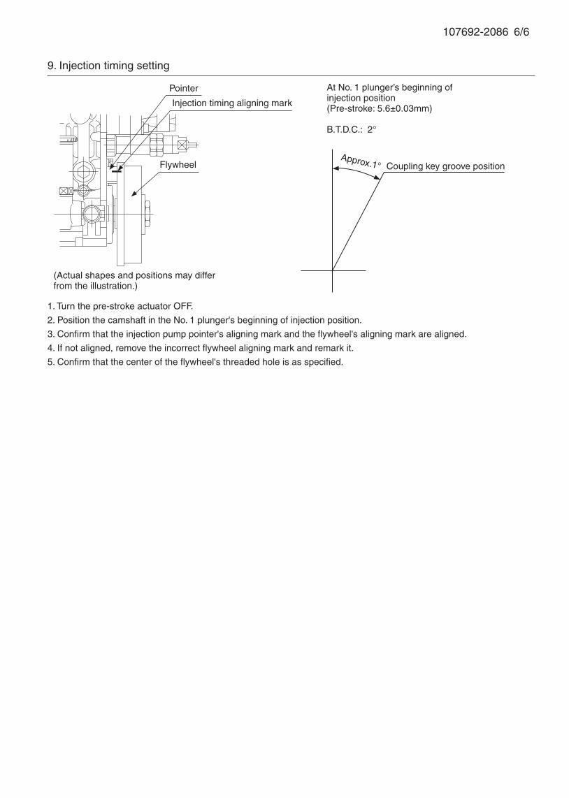
107692-2086 6/6
1. Turn the pre-stroke actuator OFF.
2. Position the camshaft in the No. 1 plunger's beginning of injection position.
3. Confirm that the injection pump pointer's aligning mark and the flywheel's aligning mark are aligned.
4. If not aligned, remove the incorrect flywheel aligning mark and remark it.
5. Confirm that the center of the flywheel's threaded hole is as specified.
9. Injection timing setting
At No. 1 plunger’s beginning of injection position(Pre-stroke: 5.6±0.03mm)
B.T.D.C.: 2°
Injection timing aligning mark
Pointer
Flywheel
(Actual shapes and positions may differfrom the illustration.)
Coupling key groove positionApprox.1°

107692-2170 ZEXEL test values diesel fuel-injection equipment 03/10/06 11:42:27 Page 1
ZEXEL Ass'y No. 107692-2170Bosch Ass'y No.Bosch TypecodeEngine Type 6D16T5Manufacturer MITSUBISHIEdition date 10/04/06 (8)
1 Adjustment conditionsCAT Designation Unit Set value min. max. Actual values OT
Test oil ISO4113 or {SAEJ967d}
...P Test Oil Temperature degC 40 40 45
Nozzle and nozzle holder 105780-8250Bosch type code 1 688 901 101Nozzle 105780-0120Bosch type code 1 688 901 990Nozzle holder 105780-2190
P Opening Pressure MPa 20.7P Opening Pressure kgf/cm2 211
Injection pipe mm 8-3-600Outer diameter - inner diameter - length (mm)
Overflow valve 131424-8420P Overflow valve opening pressure kPa 255 221 289P Overflow valve opening pressure kgf/cm2 2.6 2.25 2.95P Tester oil delivery pressure kPa 255 255 255P Tester oil delivery pressure kgf/cm2 2.6 2.6 2.6P PS/ACT control unit part no. 407980-224*P Digi switch no. 17
Direction of rotation (viewed from drive side) LLeft
2 Adjustment specification2.1 Injection timing adjustmentCAT Designation Unit Set value min. max. Actual values OT
P Direction of rotation (viewed from drive side) LLeft
P Injection order 1-5-3-6-2-4S Pre-stroke mm 5.6 5.57 5.63P Beginning of injection position NO.1
Governor sideS Difference between angles 1 deg. 60 59.75 60.25
Cal 1-5S Difference between angles 2 deg. 120 119.75 120.25
Cal 1-3S Difference between angles 3 deg. 180 179.75 180.25
Cal 1-6S Difference between angles 4 deg. 240 239.75 240.25
Cyl.1-2S Difference between angles 5 deg. 300 299.75 300.25
Cal 1-42.2 Injection quantity adjustmentCAT Designation Unit Set value min. max. Actual values OT
P Adjusting point -P Rack position 13.4P Pump speed r/min 700 700 700S Average injection quantity mm3/st. 122 120 124S Max variation between cylinders % 0 -3 3P Basic *P Fixing the rack *P PS407980-224* V 2.25+-0.01P PS407980-224* mm 3.6+-0.05P Standard for adjustment of the maximum var
iation between cylinders*
S = Setting value, C = Check value)OT = Outside Tolerance (X is set)
107692-2170 ZEXEL test values diesel fuel-injection equipment 03/10/06 11:42:27 Page 2
CAT Designation Unit Set value min. max. Actual values OTP Adjusting point ZP Rack position 7.7+-0.5P Pump speed r/min 510 510 510S Average injection quantity mm3/st. 10.5 8.7 12.3S Max variation between cylinders % 0 -15 15P Fixing the rack *P PS407980-224* V V1+0.05+-0.01P PS407980-224* mm 5.5+-0.03P Standard for adjustment of the maximum var
iation between cylinders*
RemarksRefer to items regarding the pre-stroke actuator
CAT Designation Unit Set value min. max. Actual values OTP Adjusting point AP Rack position R1(13.4)P Pump speed r/min 700 700 700S Average injection quantity mm3/st. 122 121 123P Basic *P Fixing the lever *P Boost pressure kPa 36 36P Boost pressure mmHg 270 270P PS407980-224* V 2.25+-0.01P PS407980-224* mm 3.6+-0.05
CAT Designation Unit Set value min. max. Actual values OTP Adjusting point BP Rack position R1+1.55P Pump speed r/min 1350 1350 1350S Average injection quantity mm3/st. 113 109 117P Fixing the lever *P Boost pressure kPa 36 36P Boost pressure mmHg 270 270P PS407980-224* V 2.25+-0.01P PS407980-224* mm 3.6+-0.05
CAT Designation Unit Set value min. max. Actual values OTP Adjusting point CP Rack position (R2-1.4)P Pump speed r/min 250 250 250S Average injection quantity mm3/st. 69 67 71P Fixing the lever *P Boost pressure kPa 0 0 0P Boost pressure mmHg 0 0 0P PS407980-224* V 2.25+-0.01P PS407980-224* mm 3.6+-0.05
CAT Designation Unit Set value min. max. Actual values OTP Adjusting point DP Rack position (R1-0.55)P Pump speed r/min 550 550 550S Average injection quantity mm3/st. 118.5 114.5 122.5P Fixing the lever *P Boost pressure kPa 36 36P Boost pressure mmHg 270 270P PS407980-224* V 2.25+-0.01P PS407980-224* mm 3.6+-0.05
S = Setting value, C = Check value)OT = Outside Tolerance (X is set)

107692-2170 ZEXEL test values diesel fuel-injection equipment 03/10/06 11:42:27 Page 3
2.3 Governor adjustmentName
T1=AC34BCL=(1.4)+-0.1mm
N:Pump speedR:Rack position (mm)(1)Torque cam stamping: T1(2)Tolerance for racks not indicated: +-0.05mm.(3)Boost compensator stroke: BCL
2.4 Boost compensator adjustmentCAT Designation Unit Set value min. max. Actual values OT
P Pump speed r/min 250 250 250P Rack position (R2-1.4)S Boost pressure kPa 8 6.7 9.3S Boost pressure mmHg 60 50 70
CAT Designation Unit Set value min. max. Actual values OTP Pump speed r/min 250 250 250P Rack position R2(R1-1.3)S Boost pressure kPa 22.7 22.7 22.7
AboutS Boost pressure mmHg 170 170 170
About
S = Setting value, C = Check value)OT = Outside Tolerance (X is set)
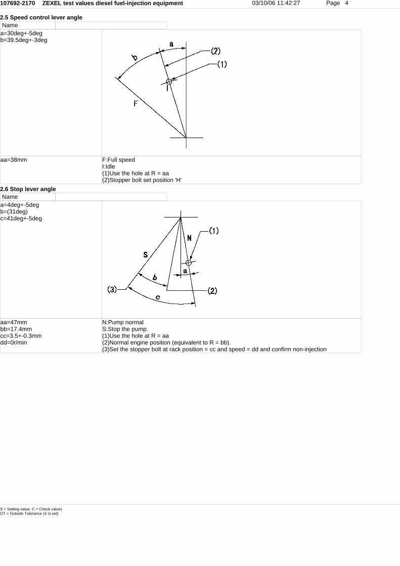
107692-2170 ZEXEL test values diesel fuel-injection equipment 03/10/06 11:42:27 Page 4
2.5 Speed control lever angleName
a=30deg+-5degb=39.5deg+-3deg
aa=38mm F:Full speedI:Idle(1)Use the hole at R = aa(2)Stopper bolt set position 'H'
2.6 Stop lever angleName
a=4deg+-5degb=(31deg)c=41deg+-5deg
aa=47mmbb=17.4mmcc=3.5+-0.3mmdd=0r/min
N:Pump normalS:Stop the pump.(1)Use the hole at R = aa(2)Normal engine position (equivalent to R = bb).(3)Set the stopper bolt at rack position = cc and speed = dd and confirm non-injection
S = Setting value, C = Check value)OT = Outside Tolerance (X is set)
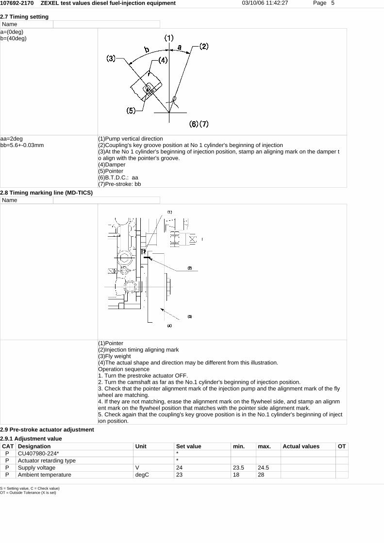
107692-2170 ZEXEL test values diesel fuel-injection equipment 03/10/06 11:42:27 Page 5
2.7 Timing settingName
a=(0deg)b=(40deg)
aa=2degbb=5.6+-0.03mm
(1)Pump vertical direction(2)Coupling's key groove position at No 1 cylinder's beginning of injection(3)At the No 1 cylinder's beginning of injection position, stamp an aligning mark on the damper to align with the pointer's groove.(4)Damper(5)Pointer(6)B.T.D.C.: aa(7)Pre-stroke: bb
2.8 Timing marking line (MD-TICS)Name
(1)Pointer(2)Injection timing aligning mark(3)Fly weight(4)The actual shape and direction may be different from this illustration.Operation sequence1. Turn the prestroke actuator OFF.2. Turn the camshaft as far as the No.1 cylinder's beginning of injection position.3. Check that the pointer alignment mark of the injection pump and the alignment mark of the flywheel are matching.4. If they are not matching, erase the alignment mark on the flywheel side, and stamp an alignment mark on the flywheel position that matches with the pointer side alignment mark.5. Check again that the coupling's key groove position is in the No.1 cylinder's beginning of injection position.
2.9 Pre-stroke actuator adjustment2.9.1 Adjustment valueCAT Designation Unit Set value min. max. Actual values OT
P CU407980-224* *P Actuator retarding type *P Supply voltage V 24 23.5 24.5P Ambient temperature degC 23 18 28
S = Setting value, C = Check value)OT = Outside Tolerance (X is set)
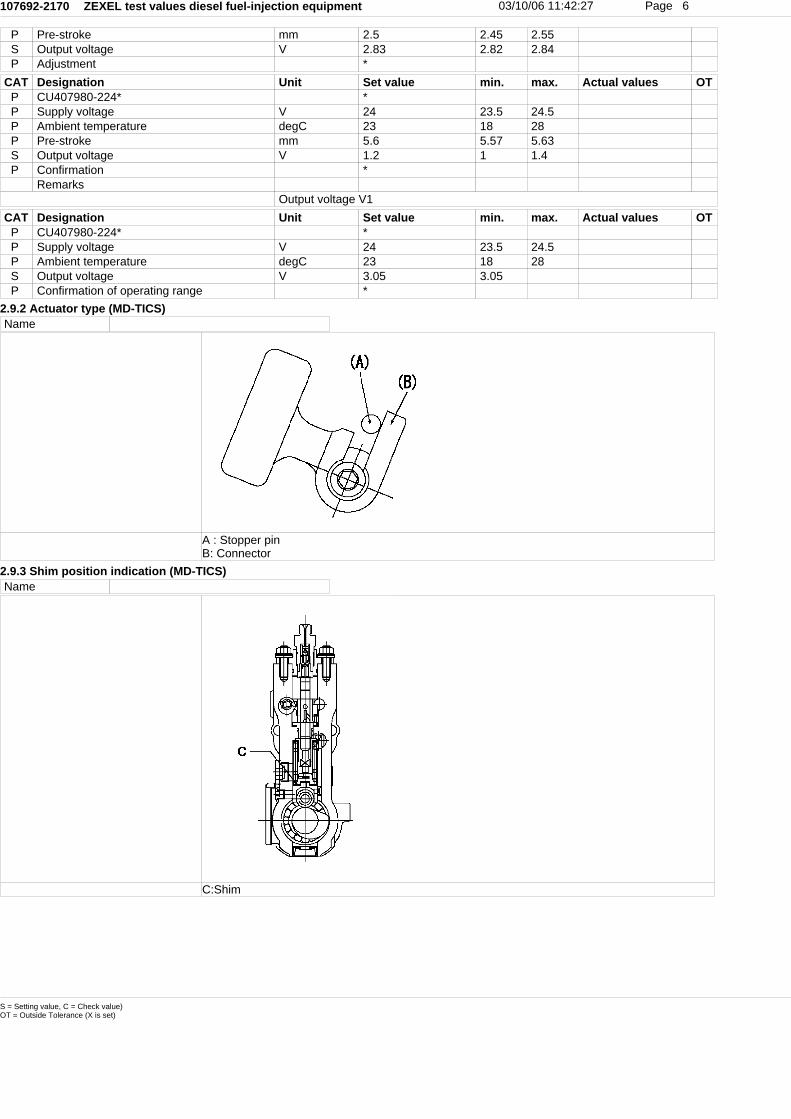
107692-2170 ZEXEL test values diesel fuel-injection equipment 03/10/06 11:42:27 Page 6
P Pre-stroke mm 2.5 2.45 2.55S Output voltage V 2.83 2.82 2.84P Adjustment *
CAT Designation Unit Set value min. max. Actual values OTP CU407980-224* *P Supply voltage V 24 23.5 24.5P Ambient temperature degC 23 18 28P Pre-stroke mm 5.6 5.57 5.63S Output voltage V 1.2 1 1.4P Confirmation *
RemarksOutput voltage V1
CAT Designation Unit Set value min. max. Actual values OTP CU407980-224* *P Supply voltage V 24 23.5 24.5P Ambient temperature degC 23 18 28S Output voltage V 3.05 3.05P Confirmation of operating range *
2.9.2 Actuator type (MD-TICS)Name
A : Stopper pinB: Connector
2.9.3 Shim position indication (MD-TICS)Name
C:Shim
S = Setting value, C = Check value)OT = Outside Tolerance (X is set)

107692-2170 ZEXEL test values diesel fuel-injection equipment 03/10/06 11:42:27 Page 7
2.9.4 Adjusting method and stamping positionName
A:Sealing positionB:Pre-stroke actuator1. When installing the pre-stroke actuator on the pump, first tighten the installation bolts loosely,then move the actuator fully clockwise (viewed from the drive side).Temporary tightening torque: 1 - 1.5 N.m (0.1 - 0.15 kgf.m)2. Move the actuator in the counterclockwise direction when viewed from the drive side, and adjust so that it becomes the adjustment point of the adjustment value. Then tighten it.Tightening torque: 7^9 N.m (0.7^0.9 kgf.m)3. After prestroke actuator installation adjustment, simultaneously stamp both the actuator side and housing side.
2.10 Additional device adjustment
S = Setting value, C = Check value)OT = Outside Tolerance (X is set)

107692-2170 ZEXEL test values diesel fuel-injection equipment 03/10/06 11:42:27 Page 8
2.10.1 Additional device 1Name RACK SENSOR
N1=1350r/minRa=R1(13.4)+1.55mm
(VR) measurement voltage(I) Part number of the control unit(G) Apply red paint.(H): End surface of the pump1. Rack sensor adjustment (-0620)(1)Fix the speed control lever at the full position(2)Set the speed to N1 r/min.(If the boost compensator is provided, apply boost pressure.)(3)Adjust the bobbin (A) so that the rack sensor's output voltage is VR+-0.01.(4)At that time, rack position must be Ra.(5)Apply G at two places.Connecting part between the joint (B) and the nut (F)Connecting part between the joint (B) and the end surface of the pump (H)
S = Setting value, C = Check value)OT = Outside Tolerance (X is set)

107692-2170 ZEXEL test values diesel fuel-injection equipment 03/10/06 11:42:27 Page 9
2.10.2 Additional device 2Name SPEED SENSOR
L=0.8~1mm (A) Flyweight projection(B) Pickup sensor(c) Lock nutSpeed sensor installation(1)Install the speed sensor so that the clearance between the sensor and the flyweight projectionis L.(This gap is the gap when the pickup sensor is returned 1 turn from where it contacts the flyweight tooth.)
S = Setting value, C = Check value)OT = Outside Tolerance (X is set)
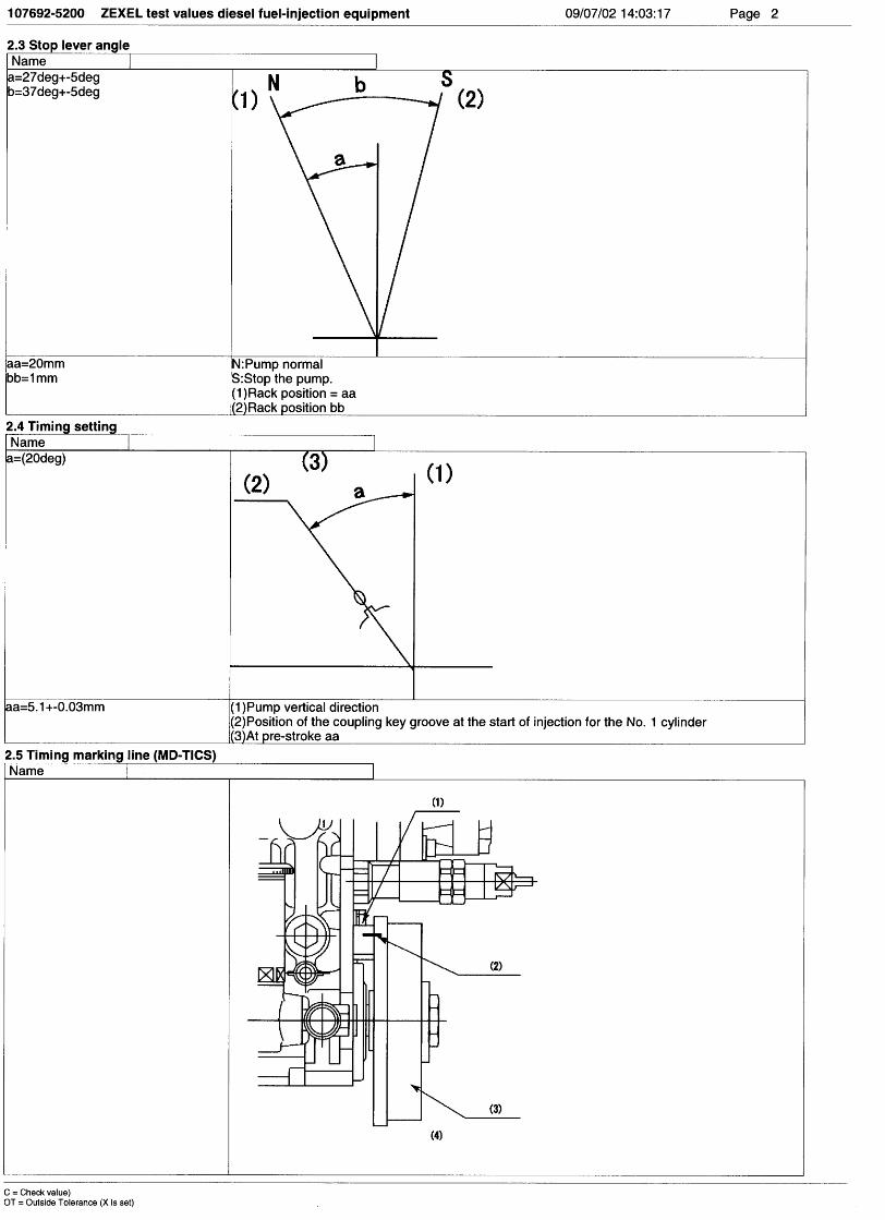
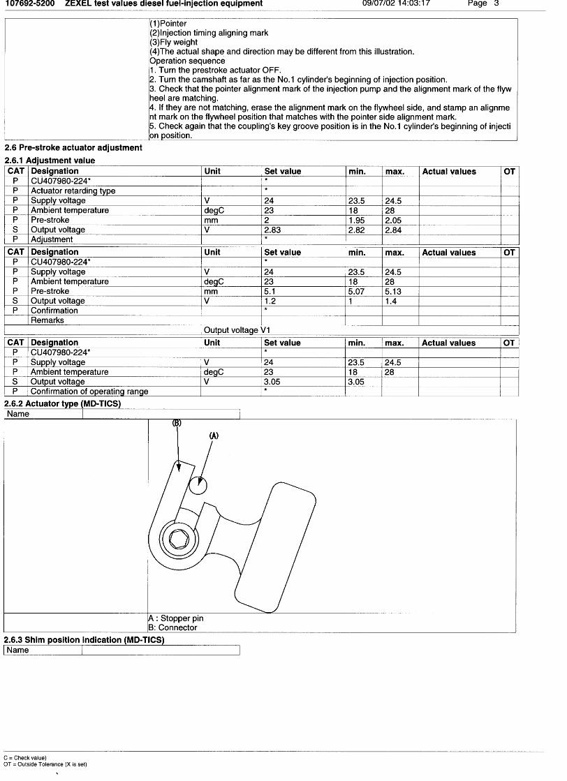
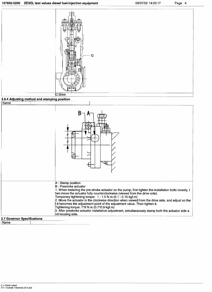
Bosch Automotive Systems Corporation
Service Department
3-4-1 Kitano, Niiza-shi, Saitama-ken, 352-8572 Japan
Tel. (048)470-1559, Fax. (048)474-9856
Company:
Ass'y No.: 108622-0106ENGINE MODEL: PF6TC
No. Governor: EP/RED-III pre-stroke actuator:
1. Test conditions
Date:
Pump rotation: clockwise ( viewed from drive side )
Injection pump: TC6HD105952-1140 159600-0420
kgf/cm2 }
CONFIDENTIAL
INJECTION PUMP CALIBRATION DATA
3 Jul 2002
NISSAN DIESEL
16801 96618
108062-3182
Injection pipe: Outer Dia. 8 mm × Inner Dia. 3 mm Length 600 mm
Nozzle opening pressure: 20.7 MPa { 211 kgf/cm2 }
Nozzle: 105780-0120 Nozzle Holder: 105780-2190(Bosch Type No. 1 688 901 990) (Bosch Type No. )
Nozzle & Nozzle Holder Ass'y: 105780-8250 (Bosch Type No. 1 688 901 101)
Overflow valve opening pressure: 255 kPa { 2.6 kgf/cm2 }
Test Oil: ISO4113 or SAE Standard Test Oil { SAE J967d } Oil Temp. 40+5 °C
5
Transfer pump pressure: 255 kPa { 2.6
1/3
DIGI Switch No. 31(For C/U 407980-224*)
2. Stop lever adjustment
R=20.0
Stop Normal
R=1.0 37°±5°
20°±5°
3. RED-III governor
Confirmation of the control rack position sensor's output characteristics
(Rack 19mm , Span 6mm)
When the rack sensor output voltages are V1 and V2, confirm that rack positions R1 and R2 are as
specified below.
Rack type 19 mm
Control unit no. 407910-3960
Output voltageV1 = (V2+0.9±0.0075)
V2 = 2.2±0.01
Rack position (mm)R2 = 11±1
R2 - R1 = 6±0.05
Rack position (mm)R1 R2
Out
put v
olta
ge (
V)
V1
V2

108622-0106 2/3
Injection order:
4. Injection timing
Pre-stroke: No.1 Plunger 6.4 ± 0.03mm V
Plungers are numbered from the Drive ° ± 30' ).side ( interval:
Note: Perform at voltage
1 4 , 1 2 , 1 6 , 1 3 , 1 560°± 15' 120°± 15' 180°± 15' 240°± 15' 300°± 15'
5. Pre-stroke actuator adjustment
• Pre-stroke: h1 = 6.4±0.03 mm (when the timing sleeve is pushed up using the jig)
• Connector angle when tightening the eccentric pin: 8°30'±30'
• Power supply voltage: 24±0.5 V
• Ambient temperature: 23±5° C
• Adjustment and confirmation
Adjustment Confirmation Confirmation Confirmation
Pre-stroke (mm) 4.0±0.05 h1 = 6.4±0.03 Below 3.4 Operation
Sensor output (V) 2.45±0.01 V1 = 1.2±0.2 3 - 0.02 Above 3.05
Pre-stroke actuator
Stamp aligning mark on housing
Tappet clearance: Manually rotate the camshaft 2 to 3 times and confirm that it rotates smoothly.
108622-0106 3/3
At No. 1 plunger’s beginning of injection position
Coupling key groove positionApprox.30°
7. Timing setting
At adjustment pre-stroke6.3±0.03(mm) (V=[V1+0.05]±0.01(V))
Rackposition
(mm)
Vist(mm)
Pumpspeed(r/min)
Injection q'ty(cm3 / 1000 strokes )
Max. variationbetween
cylinders (%)Remarks
(16.1) 1.43 600 192 ± 2 ± 4 Basic
(8.6) Approx.2.6 300 13.3 ± 1 ± 10
6. Injection quantity
At adjustment pre-stroke4.0±0.05(mm) (V=2.45±0.01(V))


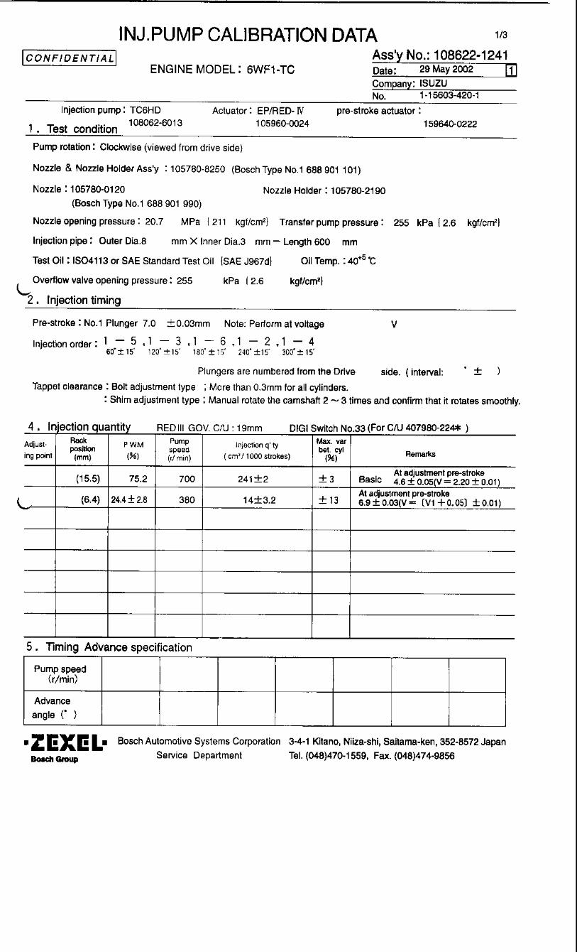
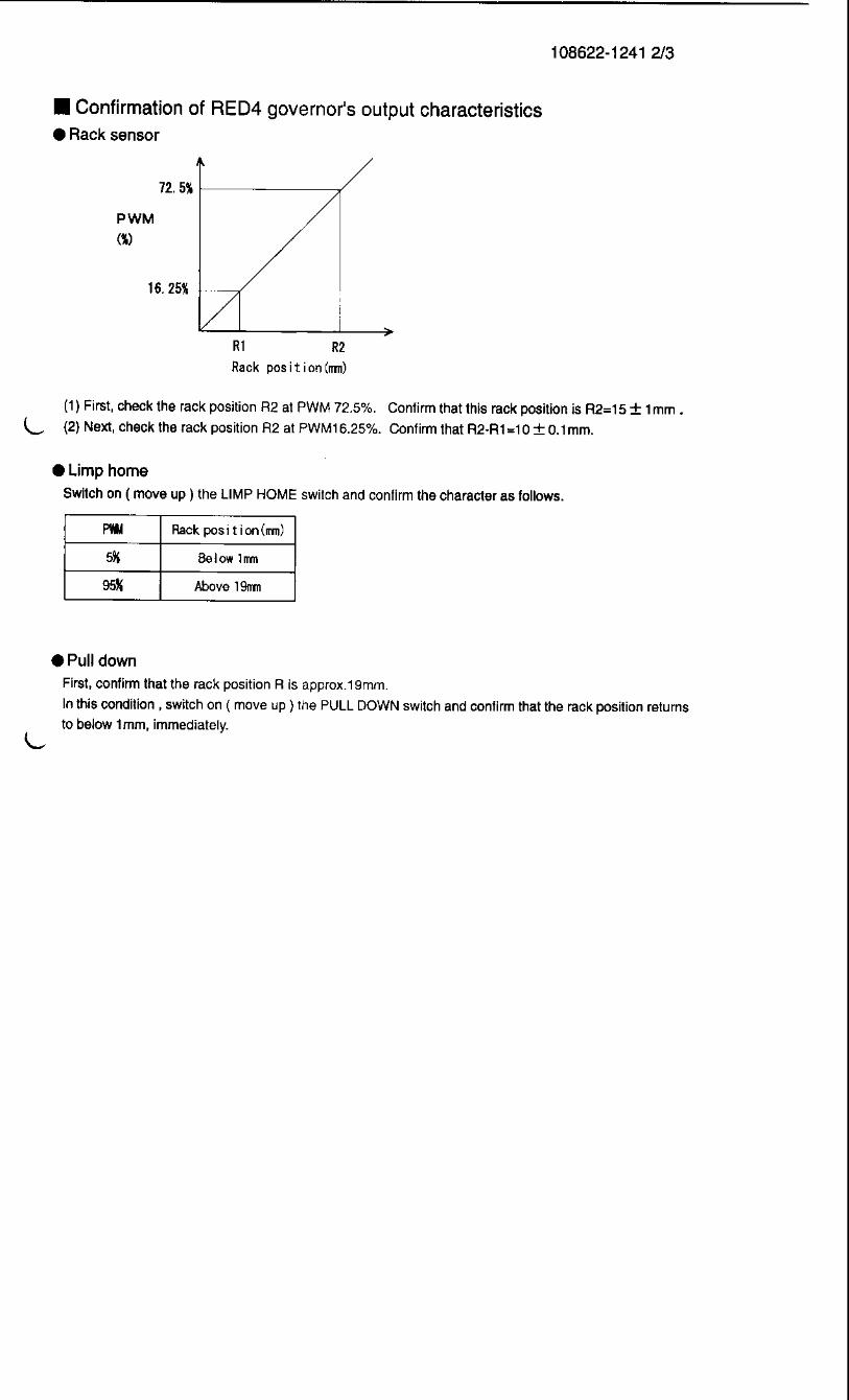


Bosch Automotive Systems Corporation
Service Department
3-4-1 Kitano, Niiza-shi, Saitama-ken, 352-8572 Japan
Tel. (048)470-1559, Fax. (048)474-9856
Company:
Ass'y No.: 108622-2080ENGINE MODEL: 6D40T1
No. Governor: EP/RED-III pre-stroke actuator:
1. Test conditions
Date:
Pump rotation: counter clockwise ( viewed from drive side )
Injection pump: TC6HD105952-1480 159600-3420
kgf/cm2 }
CONFIDENTIAL
INJECTION PUMP CALIBRATION DATA
3 Jul 2002
MITSUBISHI
ME121502
108062-3192
Injection pipe: Outer Dia. 8 mm × Inner Dia. 3 mm Length 600 mm
Nozzle opening pressure: 20.7 MPa { 211 kgf/cm2 }
Nozzle: 105780-0120 Nozzle Holder: 105780-2190(Bosch Type No. 1 688 901 990) (Bosch Type No. )
Nozzle & Nozzle Holder Ass'y: 105780-8250 (Bosch Type No. 1 688 901 101)
Overflow valve opening pressure: 255 kPa { 2.6 kgf/cm2 }
Test Oil: ISO4113 or SAE Standard Test Oil { SAE J967d } Oil Temp. 40+5 °C
1
Transfer pump pressure: 255 kPa { 2.6
1/3
DIGI Switch No. 31(For C/U 407980-224*)
2. Stop lever adjustment
3. RED-III governor
Confirmation of the control rack position sensor's output characteristics
(Rack 15mm , Span 6mm)
When the rack sensor output voltages are V1 and V2, confirm that rack positions R1 and R2 are as
specified below.
Rack type 15 mm
Control unit no. 407910-2470
Output voltageV1 = (V2+1.2±0.01)
V2 = 1.8±0.01
Rack position (mm)R2 = 11±1
R2 - R1 = 6±0.05
Rack position (mm)R1 R2
Out
put v
olta
ge (
V)
V1
V2
R=16.0
Stop Normal
R=1.029°±5°
19°±5°
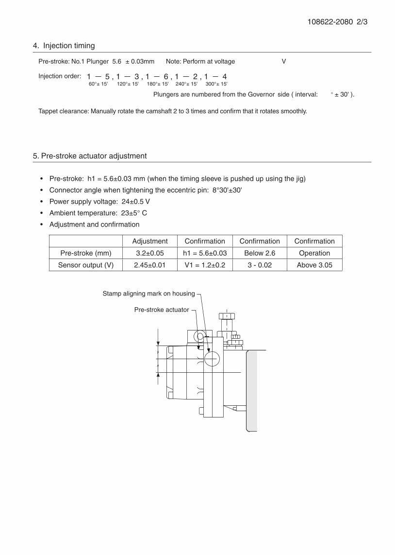
108622-2080 2/3
Injection order:
4. Injection timing
Pre-stroke: No.1 Plunger 5.6 ± 0.03mm V
Plungers are numbered from the Governor ° ± 30' ).side ( interval:
Note: Perform at voltage
5. Pre-stroke actuator adjustment
• Pre-stroke: h1 = 5.6±0.03 mm (when the timing sleeve is pushed up using the jig)
• Connector angle when tightening the eccentric pin: 8°30'±30'
• Power supply voltage: 24±0.5 V
• Ambient temperature: 23±5° C
• Adjustment and confirmation
Adjustment Confirmation Confirmation Confirmation
Pre-stroke (mm) 3.2±0.05 h1 = 5.6±0.03 Below 2.6 Operation
Sensor output (V) 2.45±0.01 V1 = 1.2±0.2 3 - 0.02 Above 3.05
Pre-stroke actuator
Stamp aligning mark on housing
1 5 , 1 3 , 1 6 , 1 2 , 1 460°± 15' 120°± 15' 180°± 15' 240°± 15' 300°± 15'
Tappet clearance: Manually rotate the camshaft 2 to 3 times and confirm that it rotates smoothly.
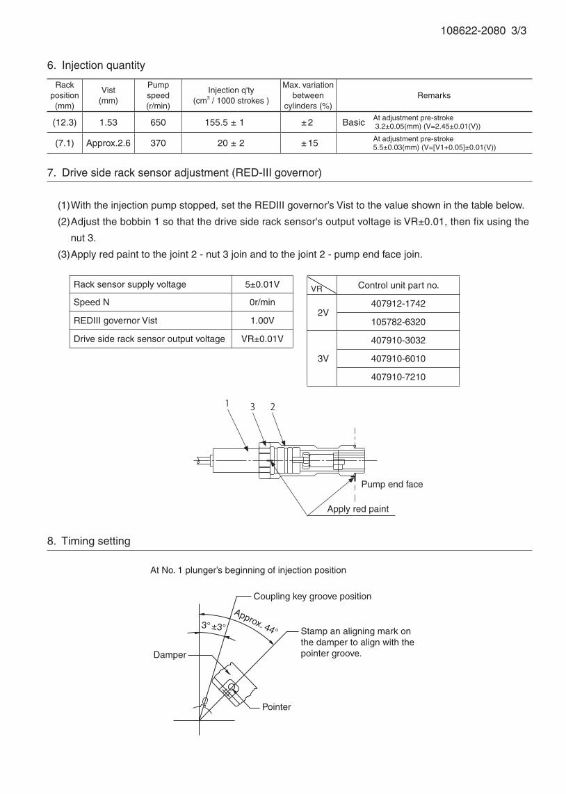
108622-2080 3/3
At adjustment pre-stroke5.5±0.03(mm) (V=[V1+0.05]±0.01(V))
Rackposition
(mm)
Vist(mm)
Pumpspeed(r/min)
Injection q'ty(cm3 / 1000 strokes )
Max. variationbetween
cylinders (%)Remarks
(12.3) 1.53 650 155.5 ± 1 ± 2 Basic
(7.1) Approx.2.6 370 20 ± 2 ± 15
6. Injection quantity
At adjustment pre-stroke 3.2±0.05(mm) (V=2.45±0.01(V))
Approx. 44°
Damper
Pointer
3° ±3° Stamp an aligning mark on the damper to align with the pointer groove.
Coupling key groove position
At No. 1 plunger’s beginning of injection position
8. Timing setting
7. Drive side rack sensor adjustment (RED-III governor)
(1) With the injection pump stopped, set the REDIII governor’s Vist to the value shown in the table below.
(2) Adjust the bobbin 1 so that the drive side rack sensor's output voltage is VR±0.01, then fix using the
nut 3.
(3) Apply red paint to the joint 2 - nut 3 join and to the joint 2 - pump end face join.
Rack sensor supply voltage 5±0.01V
Speed N 0r/min
REDIII governor Vist 1.00V
Drive side rack sensor output voltage VR±0.01V
VR Control unit part no.
2V407912-1742
105782-6320
3V
407910-3032
407910-6010
407910-7210
1 23
Apply red paint
Pump end face
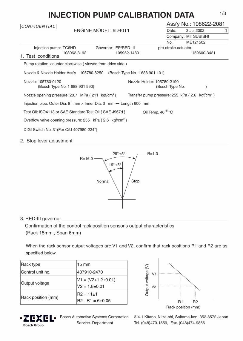
Bosch Automotive Systems Corporation
Service Department
3-4-1 Kitano, Niiza-shi, Saitama-ken, 352-8572 Japan
Tel. (048)470-1559, Fax. (048)474-9856
Company:
Ass'y No.: 108622-2081ENGINE MODEL: 6D40T1
No. Governor: EP/RED-III pre-stroke actuator:
1. Test conditions
Date:
Pump rotation: counter clockwise ( viewed from drive side )
Injection pump: TC6HD105952-1480 159600-3421
kgf/cm2 }
CONFIDENTIAL
INJECTION PUMP CALIBRATION DATA
3 Jul 2002
MITSUBISHI
ME121502
108062-3192
Injection pipe: Outer Dia. 8 mm × Inner Dia. 3 mm Length 600 mm
Nozzle opening pressure: 20.7 MPa { 211 kgf/cm2 }
Nozzle: 105780-0120 Nozzle Holder: 105780-2190(Bosch Type No. 1 688 901 990) (Bosch Type No. )
Nozzle & Nozzle Holder Ass'y: 105780-8250 (Bosch Type No. 1 688 901 101)
Overflow valve opening pressure: 255 kPa { 2.6 kgf/cm2 }
Test Oil: ISO4113 or SAE Standard Test Oil { SAE J967d } Oil Temp. 40+5 °C
1
Transfer pump pressure: 255 kPa { 2.6
1/3
DIGI Switch No. 31(For C/U 407980-224*)
2. Stop lever adjustment
3. RED-III governor
Confirmation of the control rack position sensor's output characteristics
(Rack 15mm , Span 6mm)
When the rack sensor output voltages are V1 and V2, confirm that rack positions R1 and R2 are as
specified below.
Rack type 15 mm
Control unit no. 407910-2470
Output voltageV1 = (V2+1.2±0.01)
V2 = 1.8±0.01
Rack position (mm)R2 = 11±1
R2 - R1 = 6±0.05
Rack position (mm)R1 R2
Out
put v
olta
ge (
V)
V1
V2
R=16.0
Stop Normal
R=1.029°±5°
19°±5°

108622-2081 2/3
Injection order:
4. Injection timing
Pre-stroke: No.1 Plunger 5.6 ± 0.03mm V
Plungers are numbered from the Governor ° ± 30' ).side ( interval:
Note: Perform at voltage
5. Pre-stroke actuator adjustment
• Pre-stroke: h1 = 5.6±0.03 mm (when the timing sleeve is pushed up using the jig)
• Connector angle when tightening the eccentric pin: 8°30'±30'
• Power supply voltage: 24±0.5 V
• Ambient temperature: 23±5° C
• Adjustment and confirmation
Adjustment Confirmation Confirmation Confirmation
Pre-stroke (mm) 3.2±0.05 h1 = 5.6±0.03 Below 2.6 Operation
Sensor output (V) 2.45±0.01 V1 = 1.2±0.2 3 - 0.02 Above 3.05
Pre-stroke actuator
Stamp aligning mark on housing
1 5 , 1 3 , 1 6 , 1 2 , 1 460°± 15' 120°± 15' 180°± 15' 240°± 15' 300°± 15'
Tappet clearance: Manually rotate the camshaft 2 to 3 times and confirm that it rotates smoothly.

108622-2081 3/3
At adjustment pre-stroke5.5±0.03(mm) (V=[V1+0.05]±0.01(V))
Rackposition
(mm)
Vist(mm)
Pumpspeed(r/min)
Injection q'ty(cm3 / 1000 strokes )
Max. variationbetween
cylinders (%)Remarks
(12.3) 1.53 650 155.5 ± 1 ± 2 Basic
(7.1) Approx.2.6 370 20 ± 2 ± 15
6. Injection quantity
At adjustment pre-stroke 3.2±0.05(mm) (V=2.45±0.01(V))
Approx. 44°
Damper
Pointer
3° ±3° Stamp an aligning mark on the damper to align with the pointer groove.
Coupling key groove position
At No. 1 plunger’s beginning of injection position
8. Timing setting
7. Drive side rack sensor adjustment (RED-III governor)
(1) With the injection pump stopped, set the REDIII governor’s Vist to the value shown in the table below.
(2) Adjust the bobbin 1 so that the drive side rack sensor's output voltage is VR±0.01, then fix using the
nut 3.
(3) Apply red paint to the joint 2 - nut 3 join and to the joint 2 - pump end face join.
Rack sensor supply voltage 5±0.01V
Speed N 0r/min
REDIII governor Vist 1.00V
Drive side rack sensor output voltage VR±0.01V
VR Control unit part no.
2V407912-1742
105782-6320
3V
407910-3032
407910-6010
407910-7210
1 23
Apply red paint
Pump end face
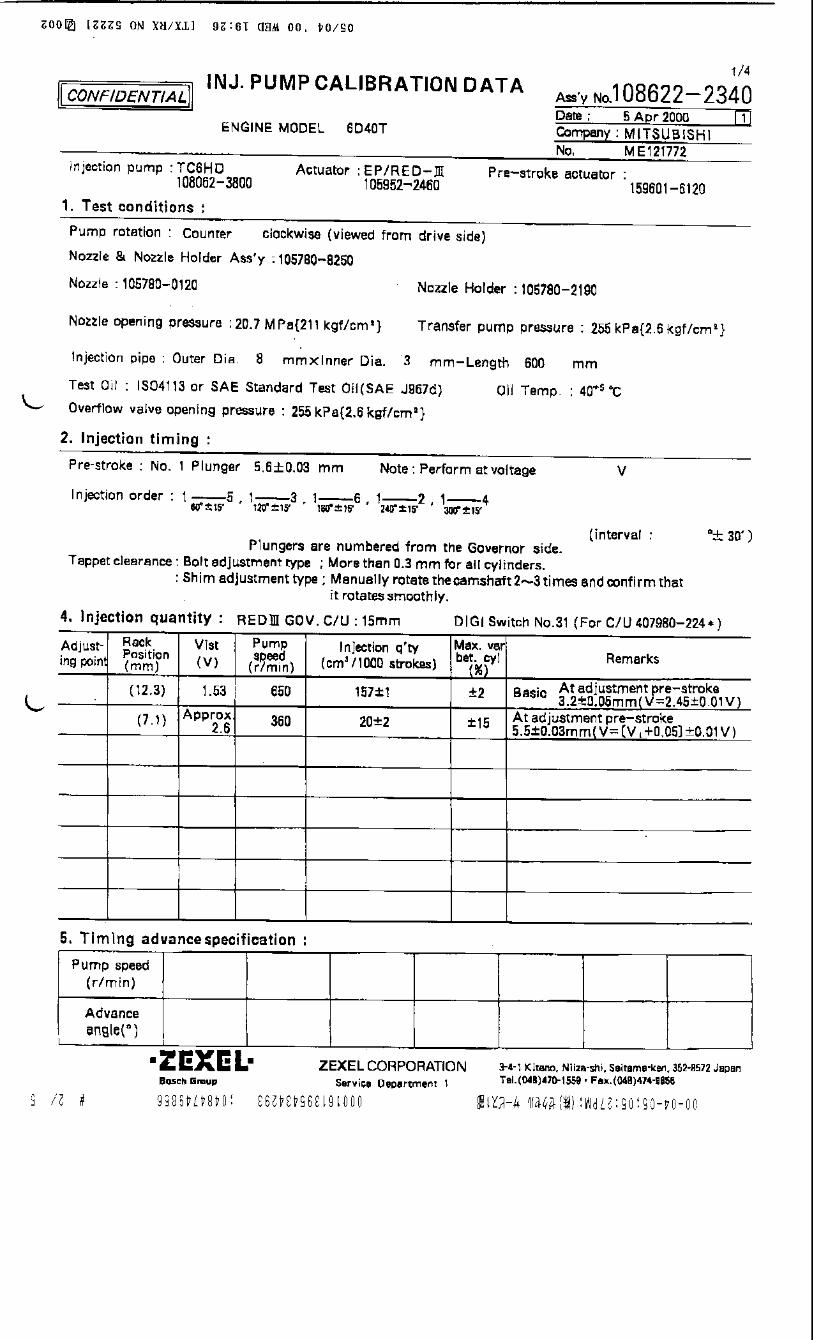

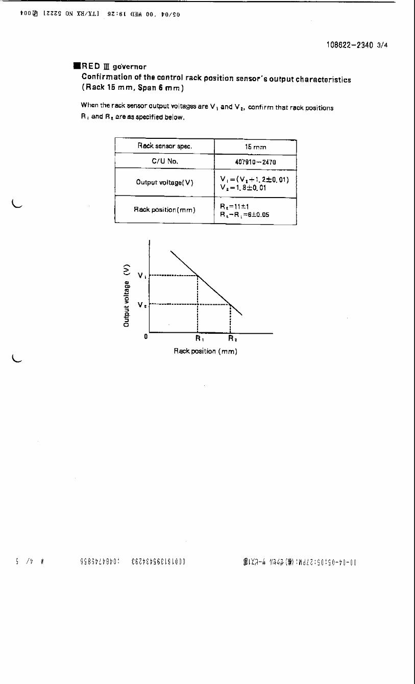
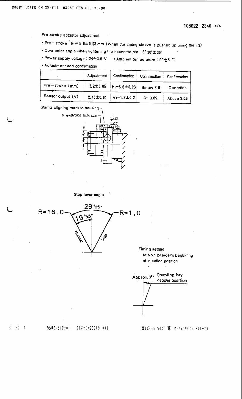
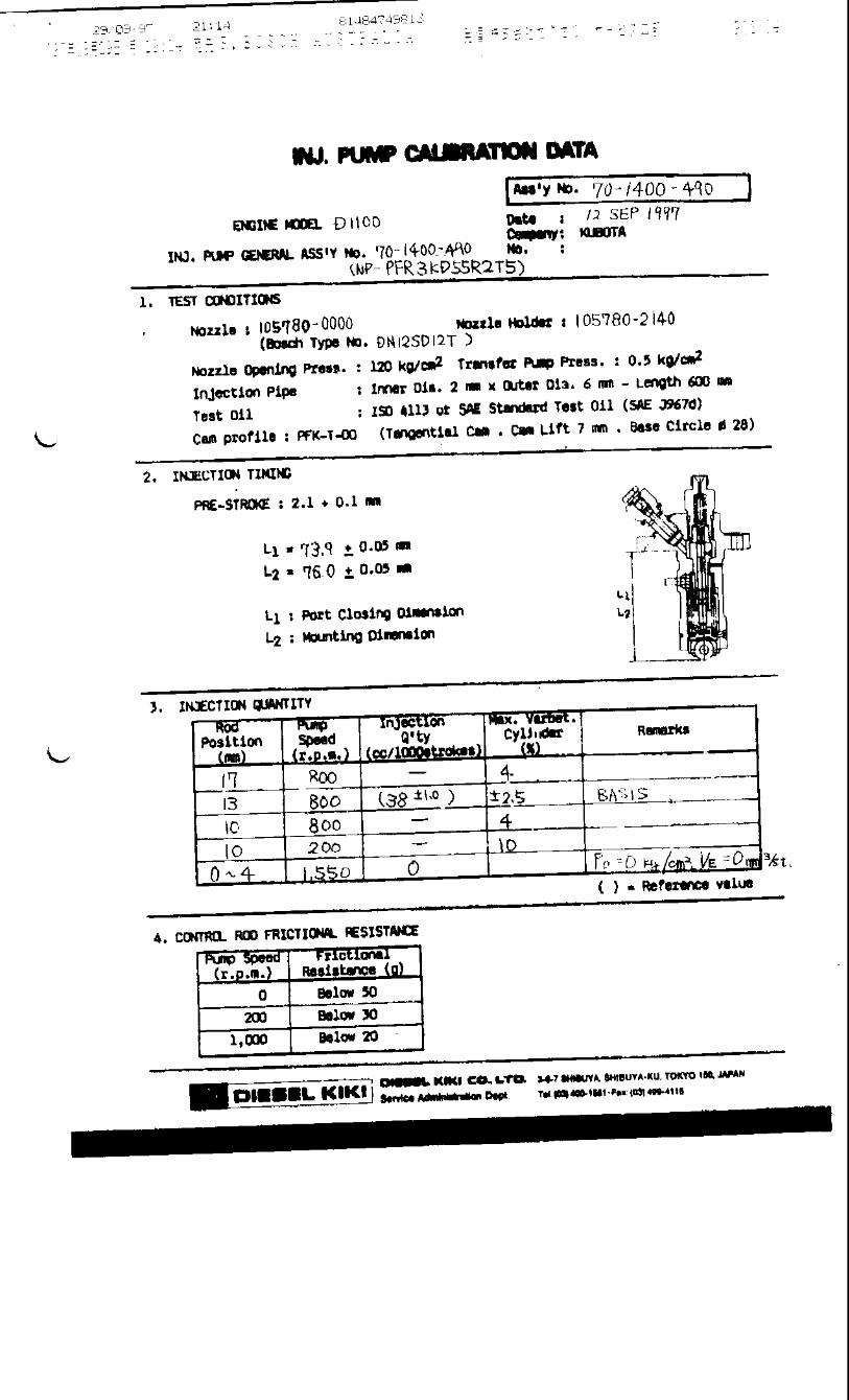

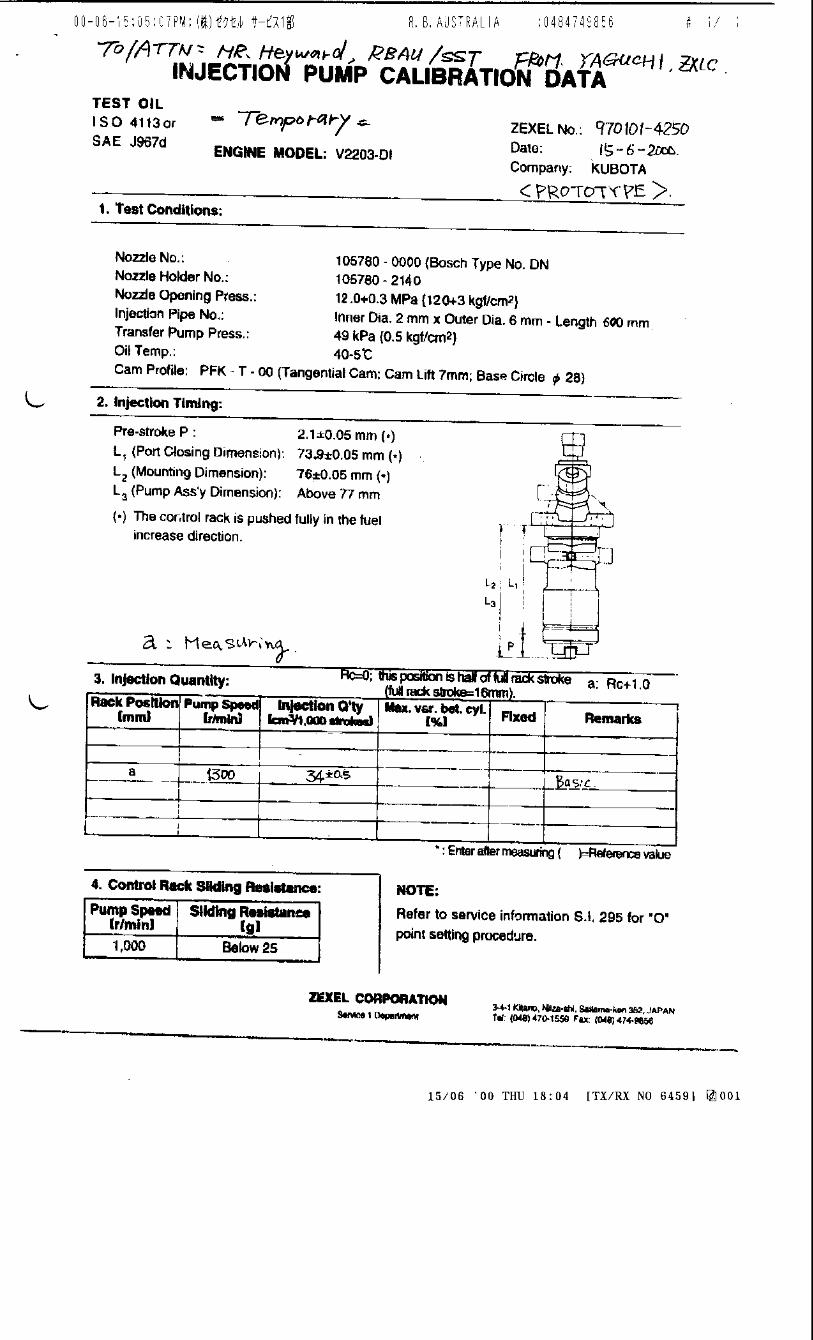
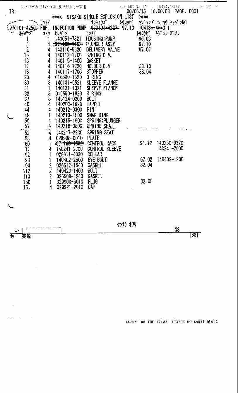

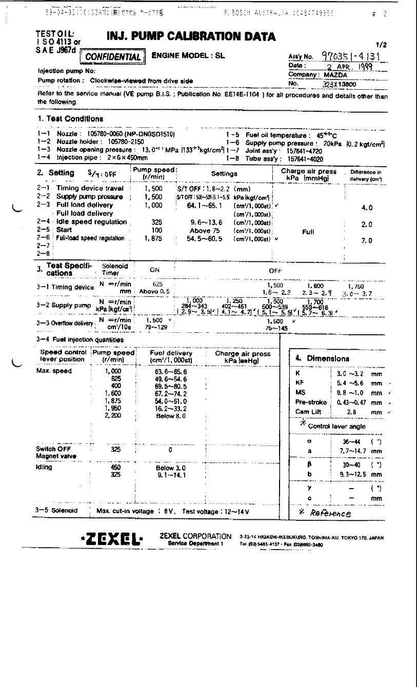
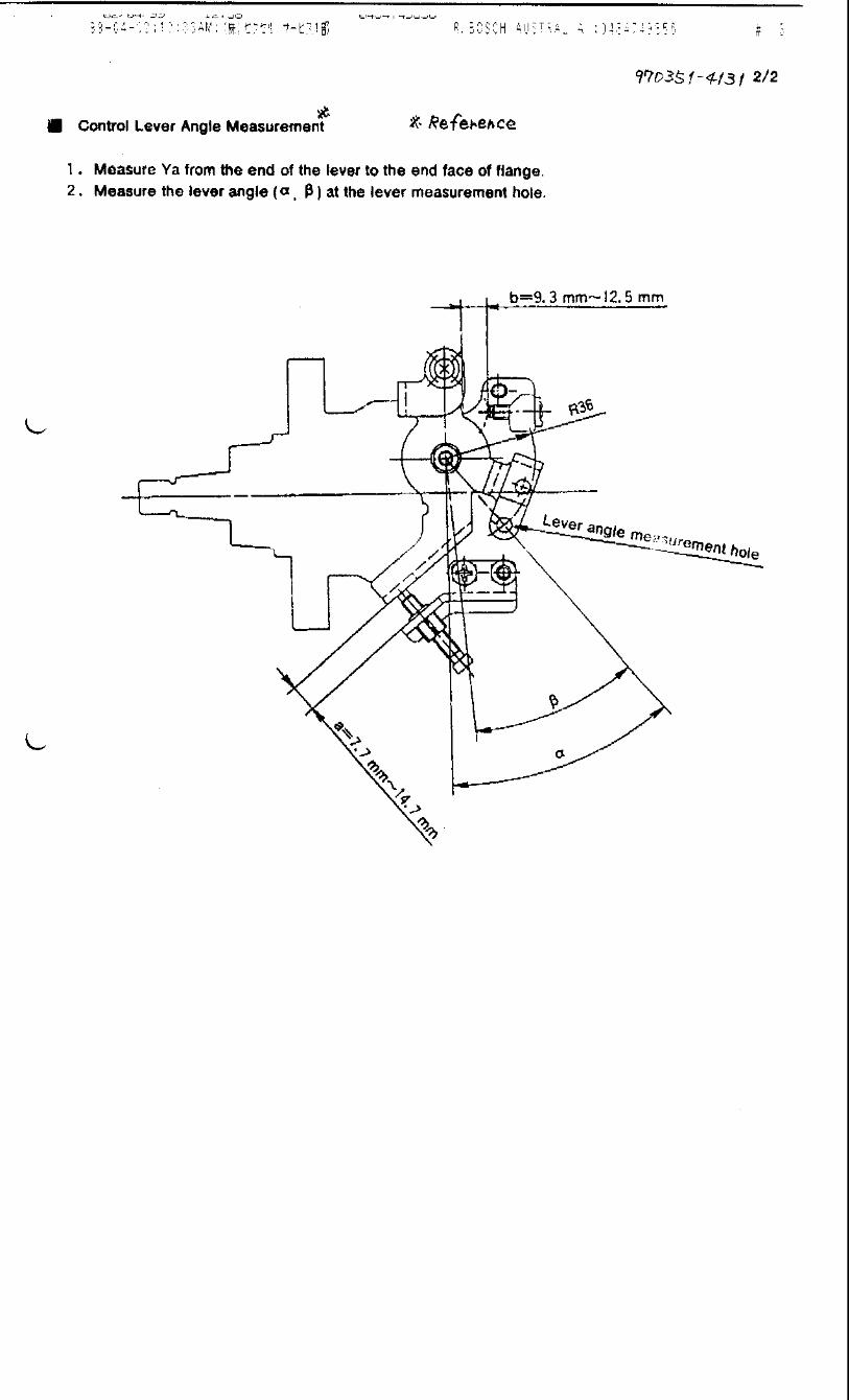
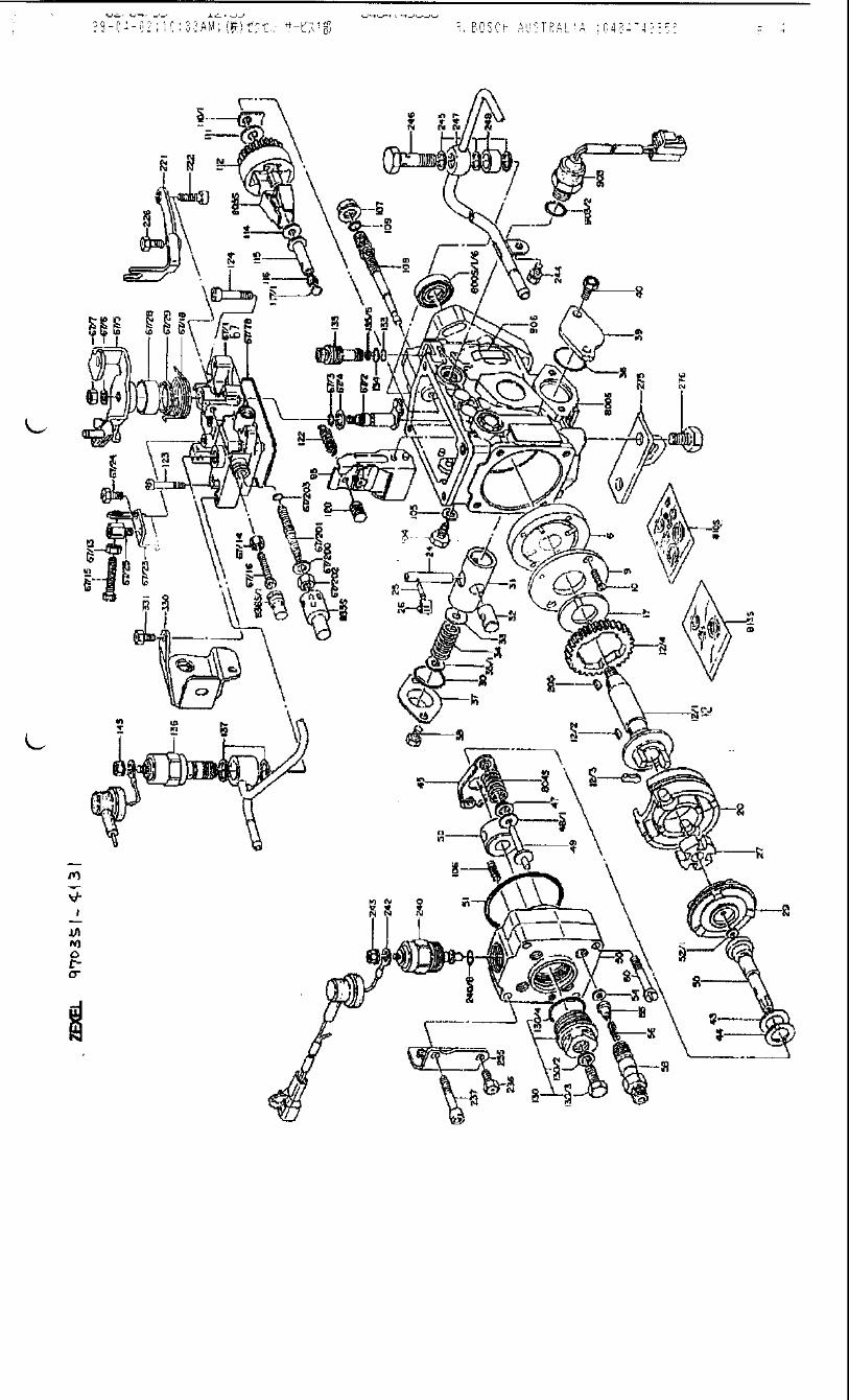

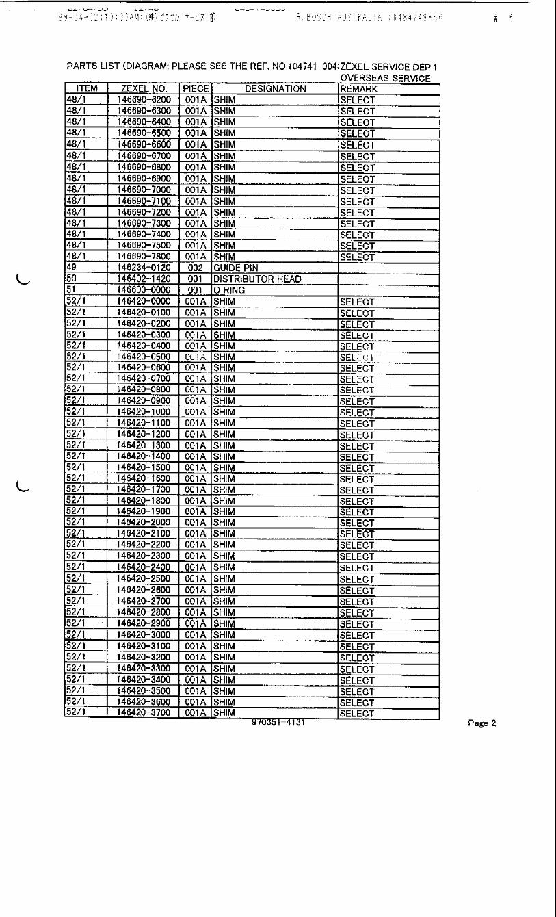
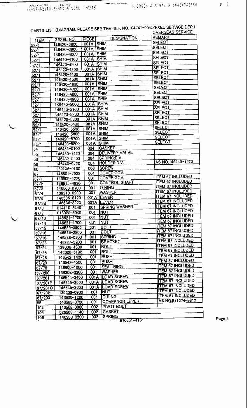
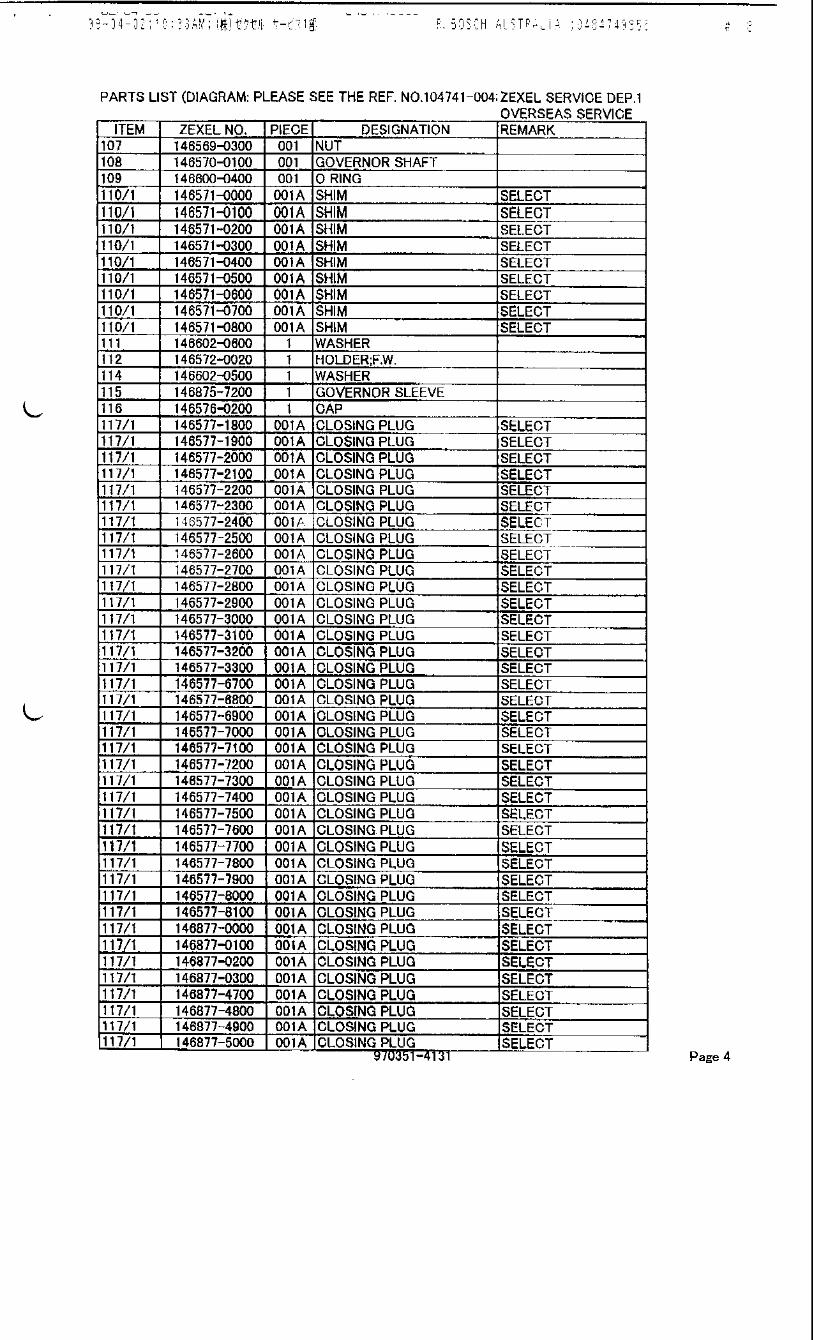
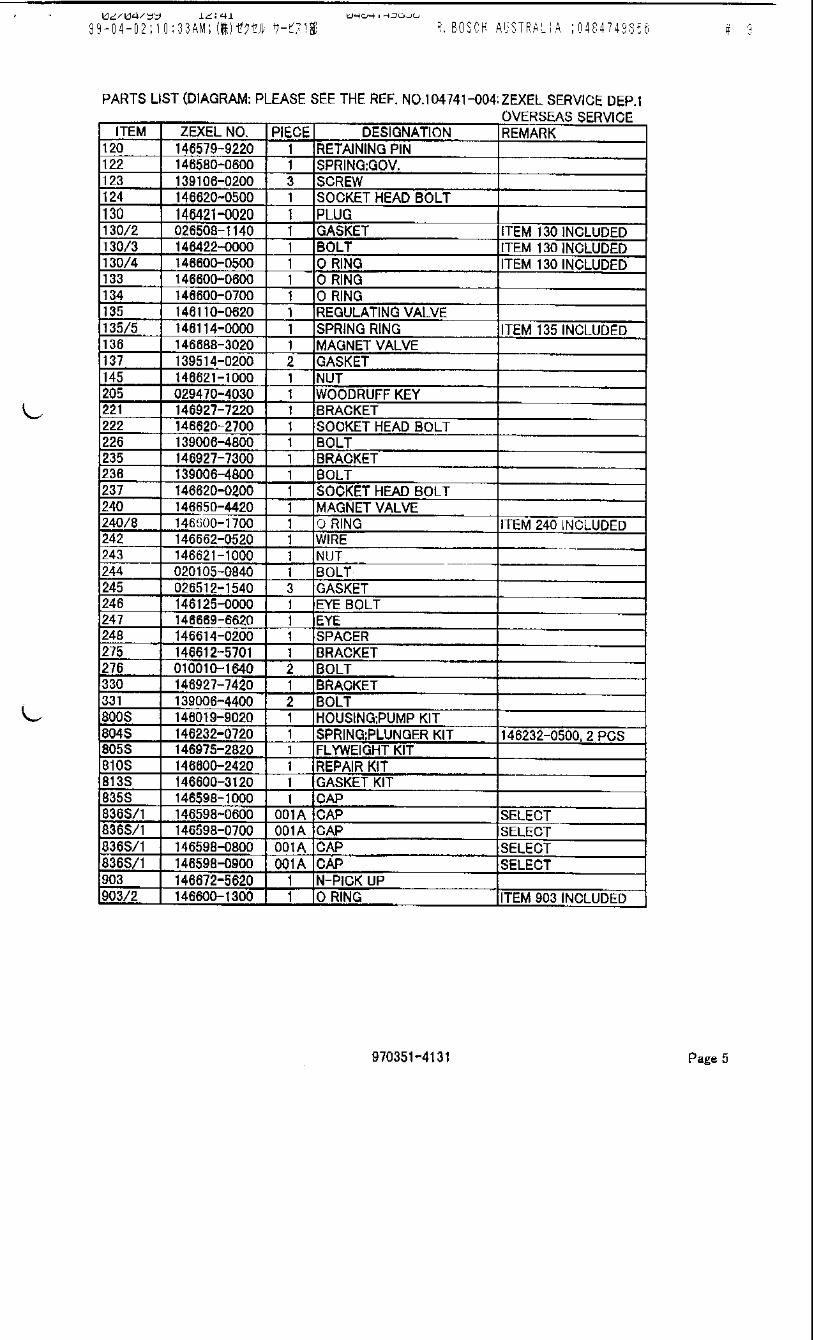

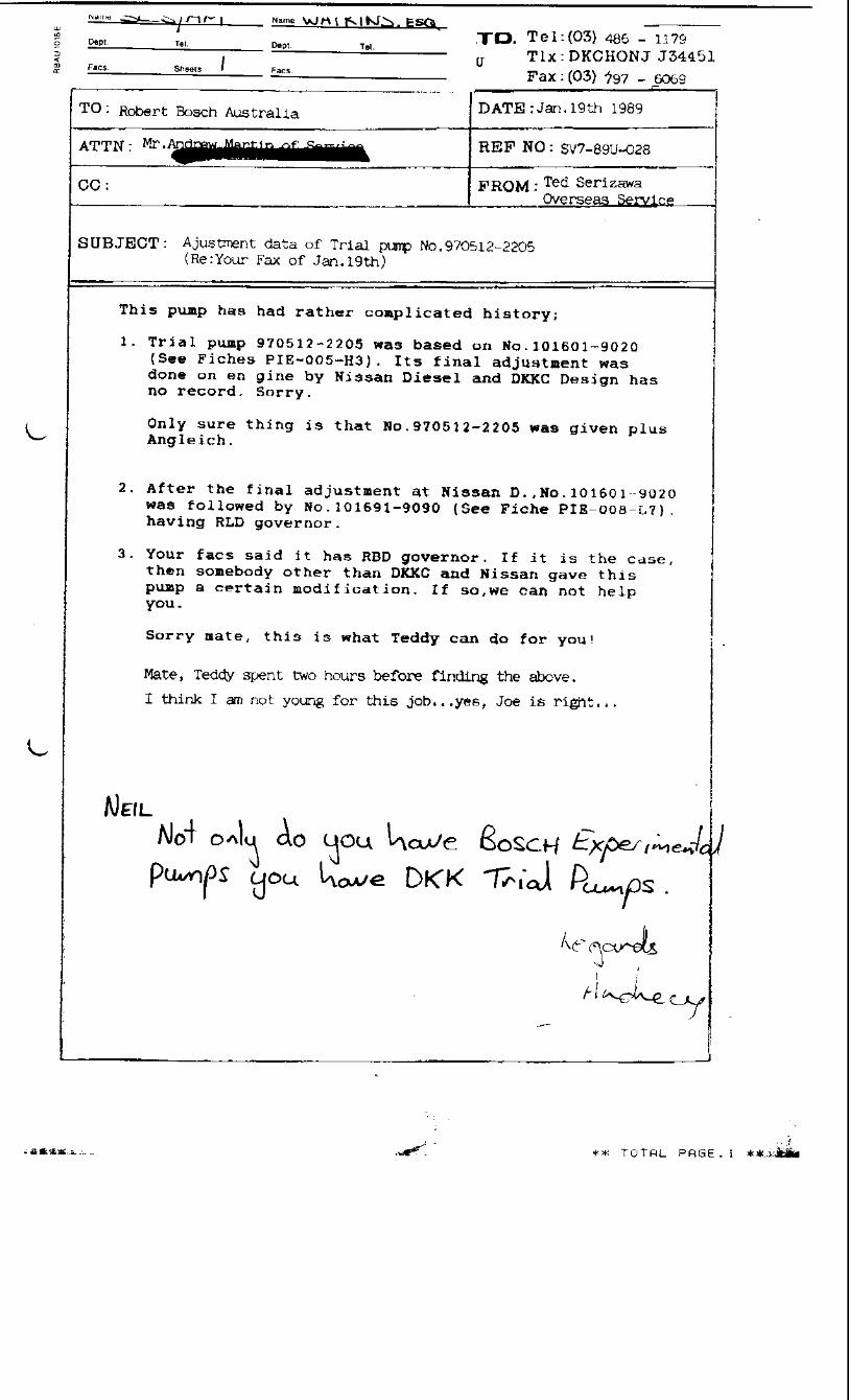
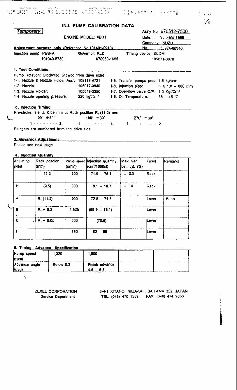

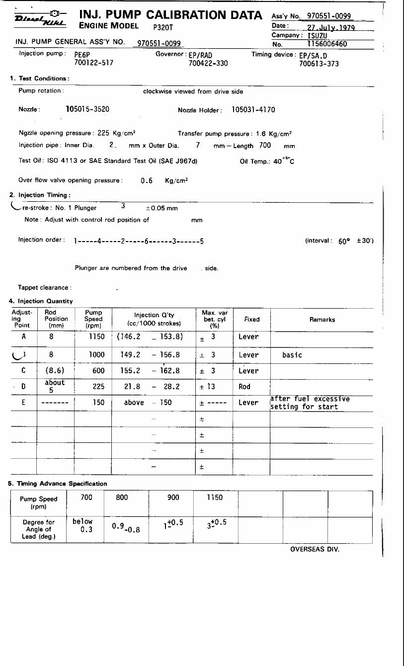
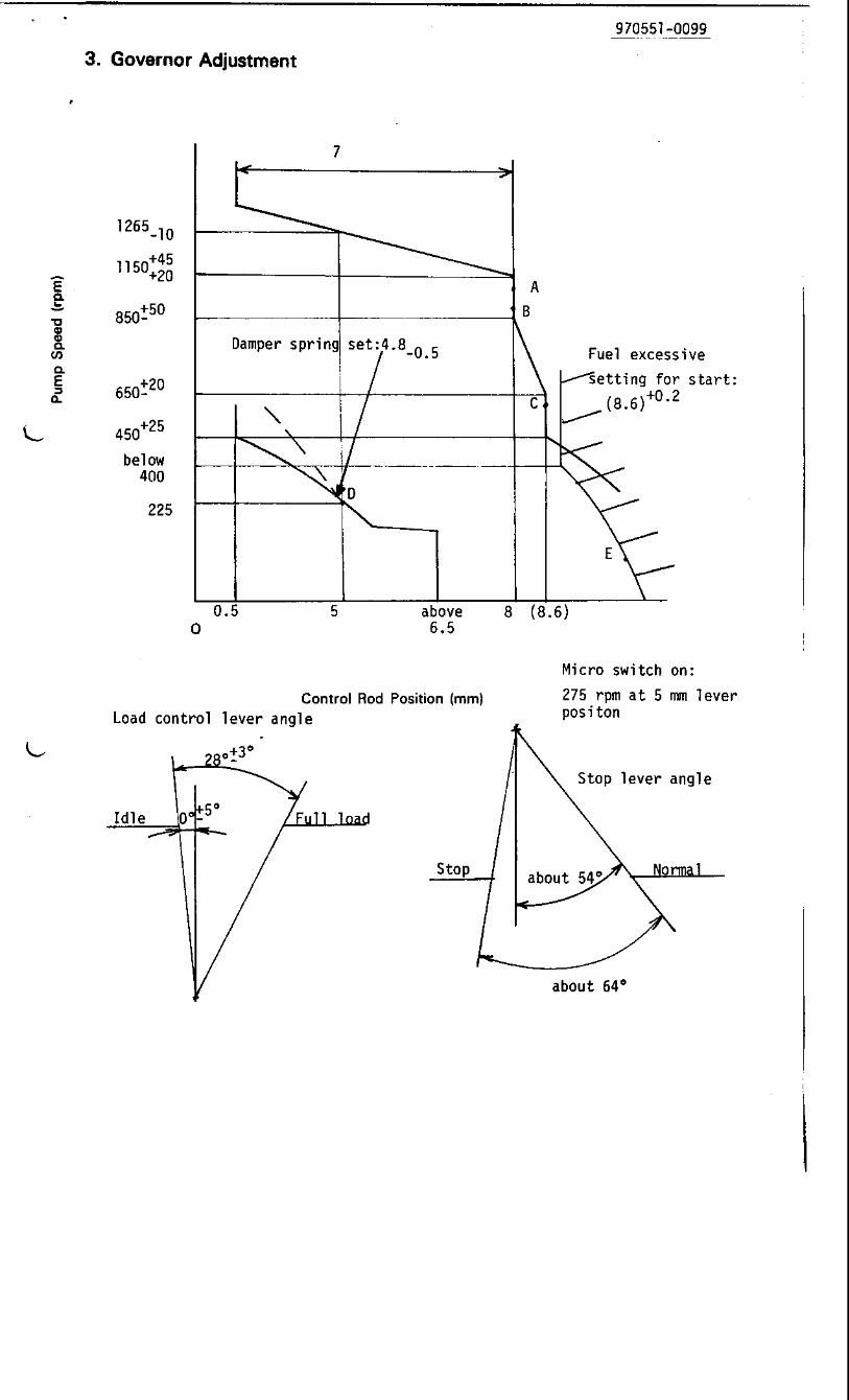
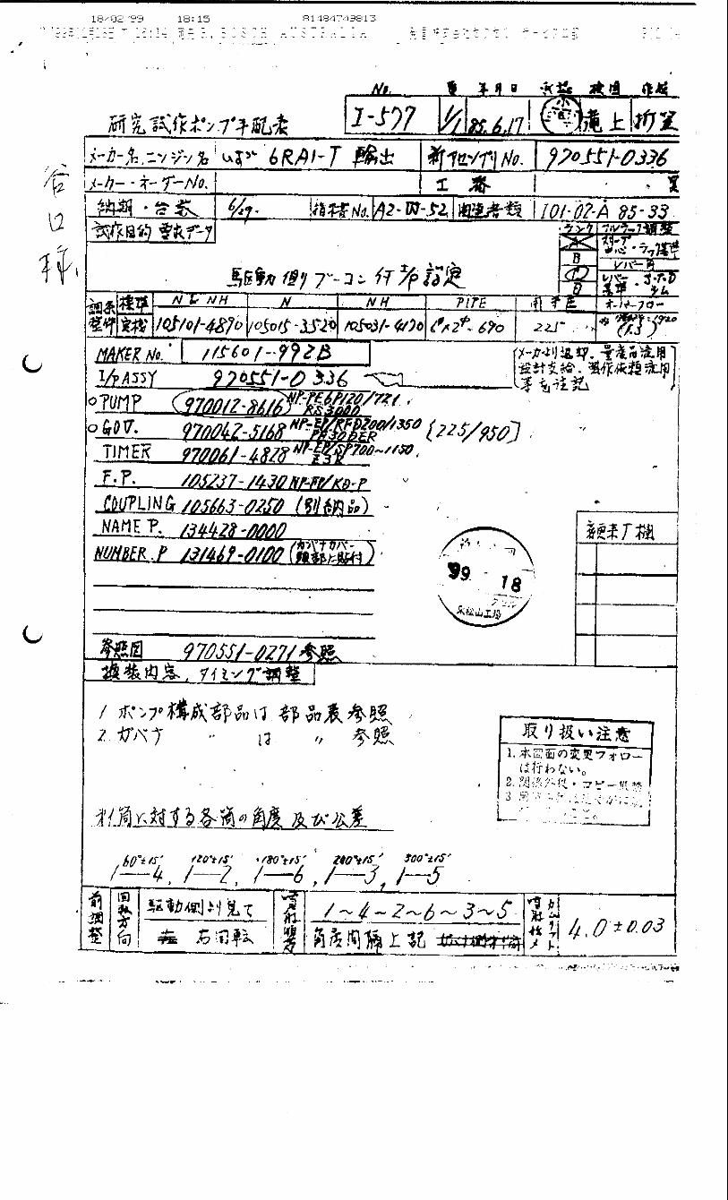
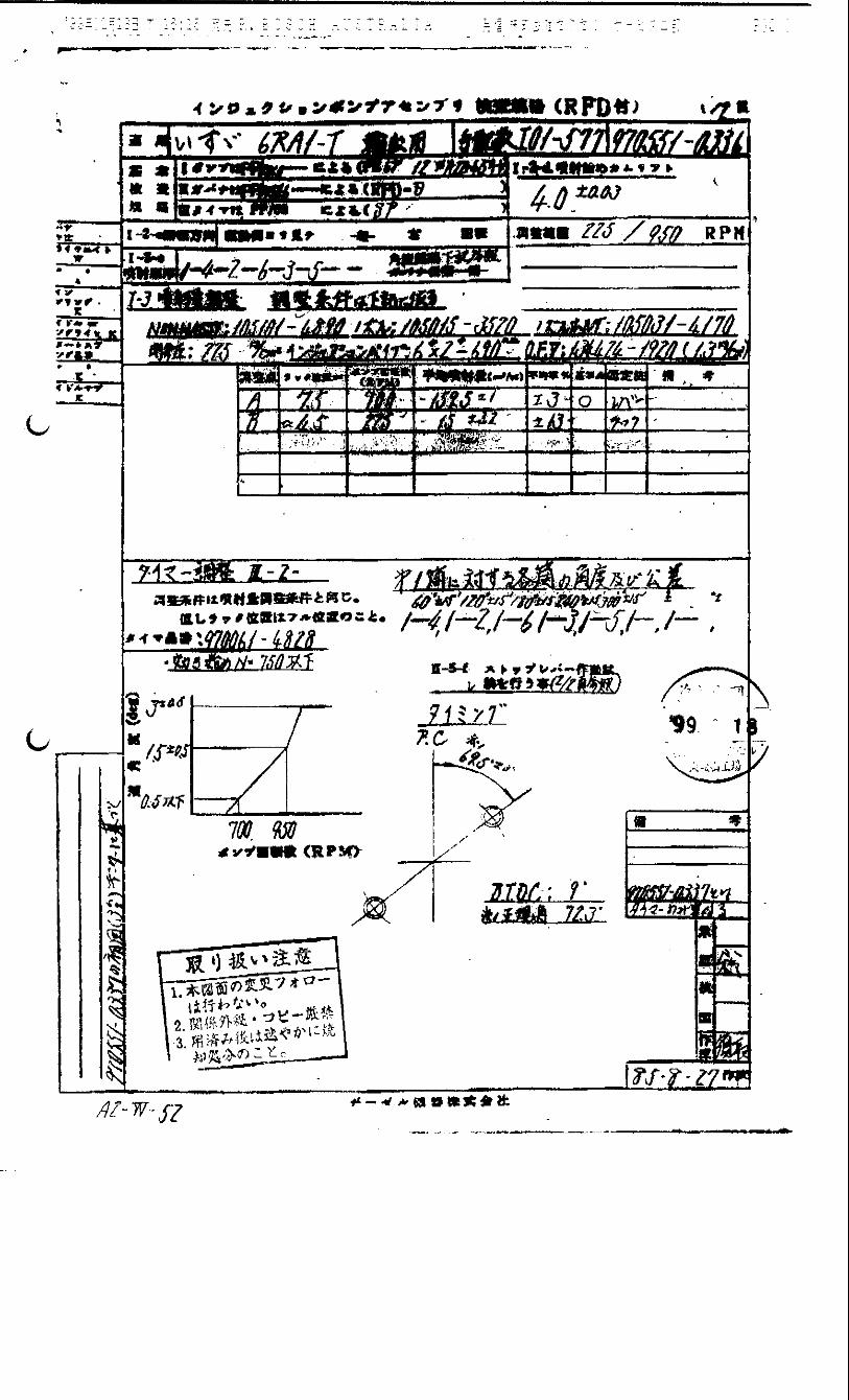
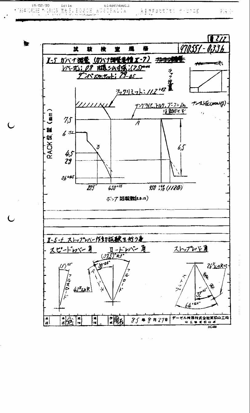
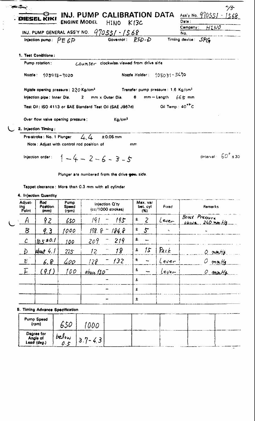
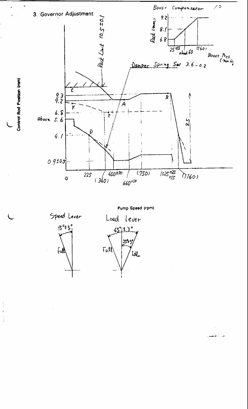
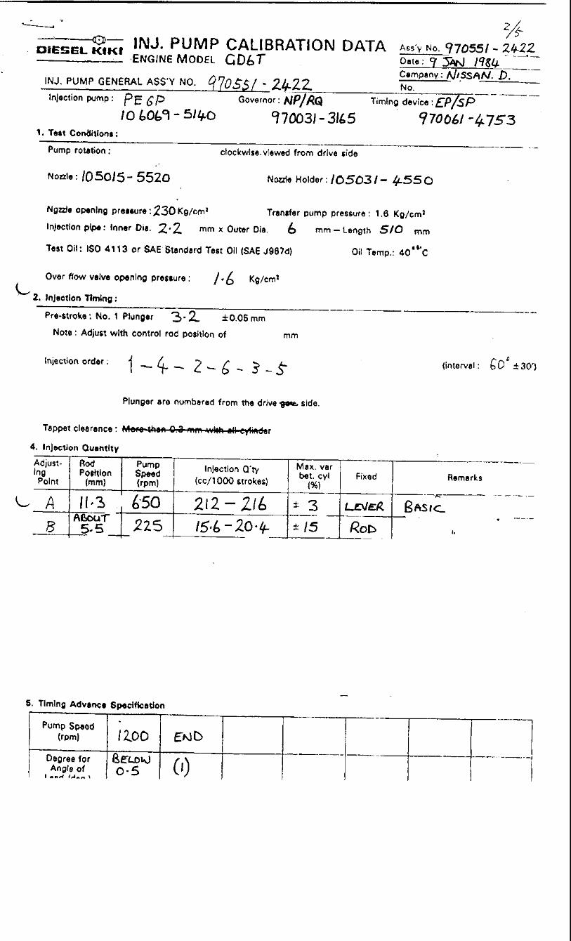
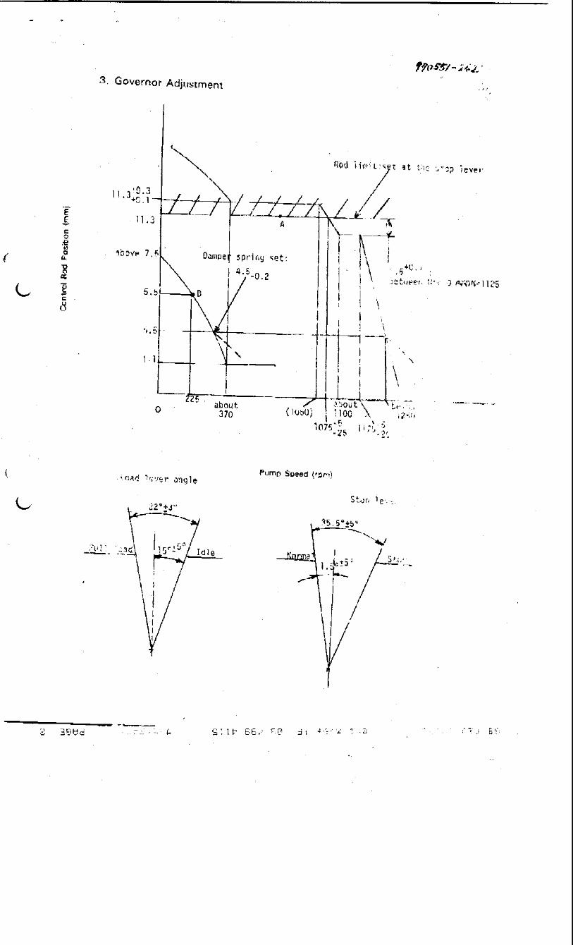
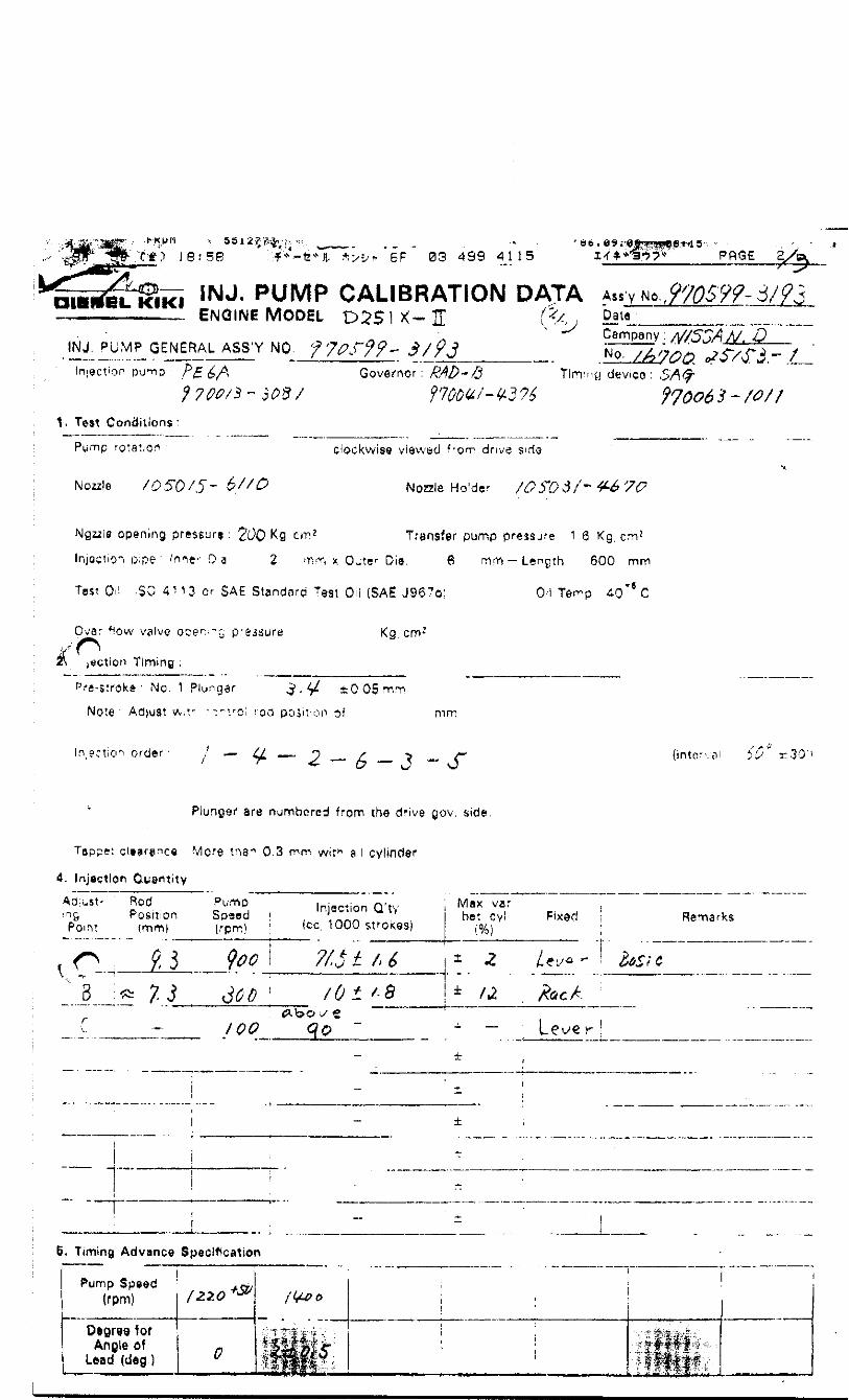
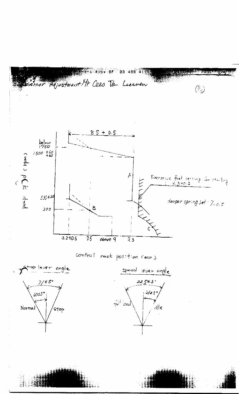
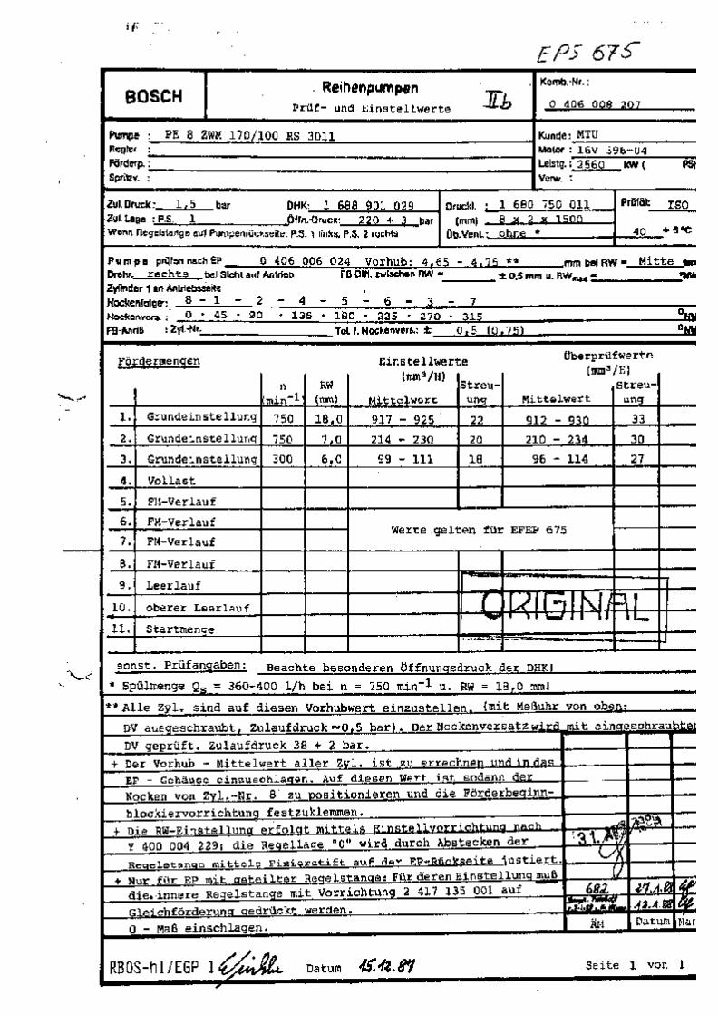
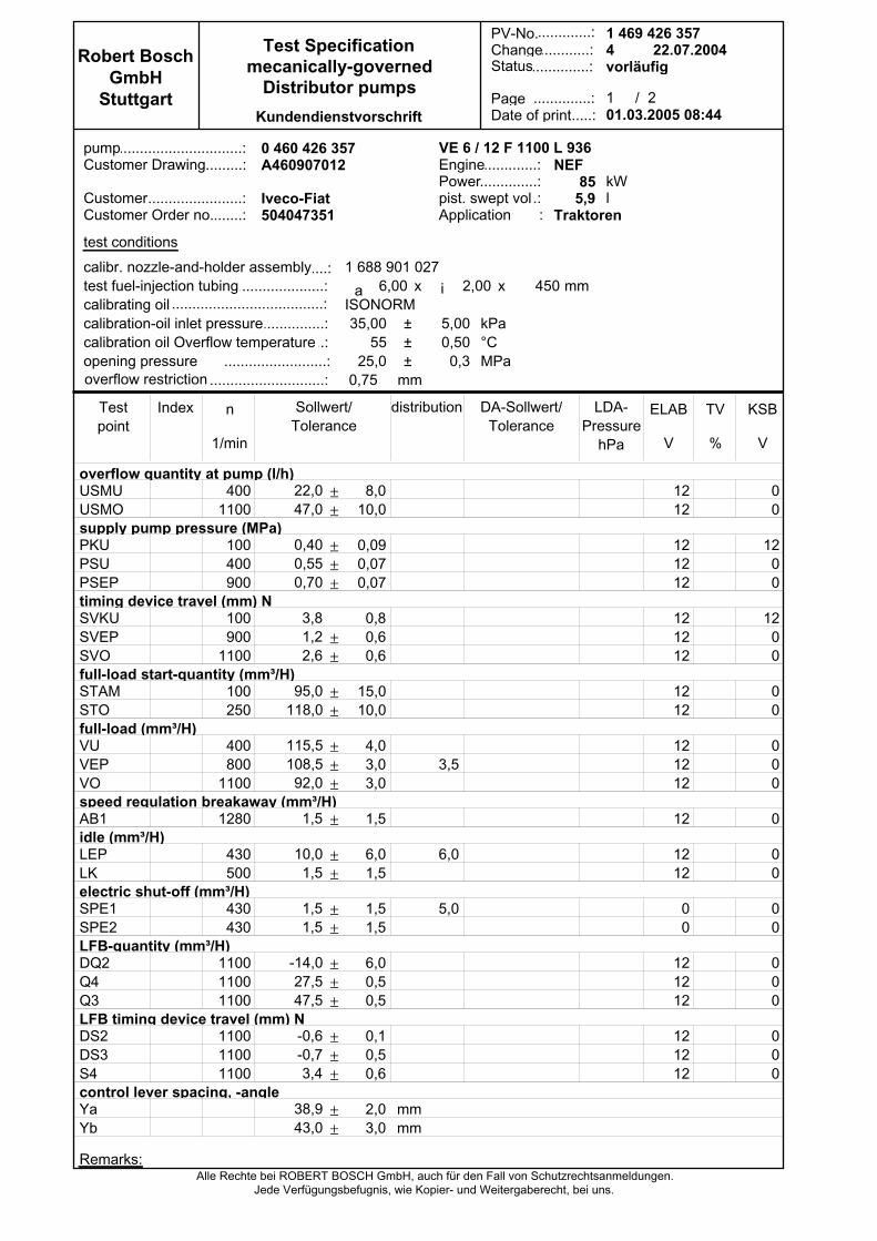
Robert BoschGmbH
Stuttgart /
.............:.............:
................:
..............:......:
1Kundendienstvorschrift
Alle Rechte bei ROBERT BOSCH GmbH, auch für den Fall von Schutzrechtsanmeldungen.Jede Verfügungsbefugnis, wie Kopier- und Weitergaberecht, bei uns.
StatusTest Specification
mecanically-governedDistributor pumps
PV-No.Change
PageDate of print
2
....................................: mm 0,75
1 688 901 027 ...................:...........................................:
...............................................:........................................:
6,00ISONORM 35,00
2,00 450 mmx x
± 5,00 kPa.......................................: 0,50
25,0 0,3±±.........................:
°CMPa
55
overflow quantity at pump (l/h)
supply pump pressure (MPa)
timing device travel (mm) N
full-load start-quantity (mm³/H)
full-load (mm³/H)
speed regulation breakaway (mm³/H)
idle (mm³/H)
electric shut-off (mm³/H)
LFB-quantity (mm³/H)
LFB timing device travel (mm) N
control lever spacing, -angle
USMUUSMO
PKUPSUPSEP
SVKUSVEPSVO
STAMSTO
VUVEPVO
AB1
LEPLK
SPE1SPE2
DQ2Q4Q3
DS2DS3S4
YaYb
4001100
100400900
100900
1100
100250
400800
1100
1280
430500
430430
110011001100
110011001100
00
1200
1200
00
000
0
00
00
000
000
±±
±±±
±±
±±
±±±
±
±±
±±
±±±
±±±
±±
mmmm
8,0 10,0
0,09 0,07 0,07
0,8 0,6 0,6
15,0 10,0
4,0 3,0 3,0
1,5
6,0 1,5
1,5 1,5
6,0 0,5 0,5
0,1 0,5 0,6
2,0 3,0
3,5
6,0
5,0
n
1/min
KSB
V
TV
%
1212
121212
121212
1212
121212
12
1212
00
121212
121212
ELAB
V
a i
22,0 47,0
0,40 0,55 0,70
3,8 1,2 2,6
95,0 118,0
115,5 108,5 92,0
1,5
10,0 1,5
1,5 1,5
-14,0 27,5 47,5
-0,6 -0,7 3,4
38,9 43,0
0 460 426 357 ..............................:pump VE 6 / 12 F 1100 L 936
85NEF
Traktoren..............: 5,9
kWl
:
..............:...............:A460907012
Iveco-Fiat504047351
............................:
..............................:.............................:
Customer Drawing
CustomerCustomer Order no.
EnginePowerpist. swept vol.Application
test conditions
Remarks:
4vorläufig
22.07.20041 469 426 357
01.03.2005 08:44
calibr. nozzle-and-holder assemblytest fuel-injection tubingcalibrating oil
overflow restriction
calibration-oil inlet pressurecalibration oil Overflow temperatureopening pressure
Testpoint
Index Sollwert/Tolerance
distribution DA-Sollwert/Tolerance
LDA-Pressure
hPa
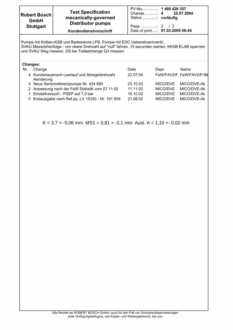
Robert BoschGmbH
Stuttgart /
.............:.............:
................:
..............:......:
2Kundendienstvorschrift
Alle Rechte bei ROBERT BOSCH GmbH, auch für den Fall von Schutzrechtsanmeldungen.Jede Verfügungsbefugnis, wie Kopier- und Weitergaberecht, bei uns.
StatusTest Specification
mecanically-governedDistributor pumps
PV-No.Change
PageDate of print
2
Nr.Kundenwuensch-Leerlauf und AbregeldrehzahlAenderungNeue Serienreferenzpumpe Nr. 424 890Anpassung nach der FeW Statistik vom 07.11.02Einstellversuch - PSEP auf 7,0 barErstausgabe nach Ref.pp. LV 15330 - Nr. 191 509
22.07.04
23.10.0311.11.0216.10.0221.08.02
FeW/FAV2/P
MICO/DVEMICO/DVEMICO/DVEMICO/DVE
FeW/FAV2/P-Bk
MICO/DVE-AkMICO/DVE-AkMICO/DVE-AkMICO/DVE-Ak
4
3210
Changes:
Pumpe mit Kolben-KSB und Badewanne LFB, Pumpe mit EDC Ueberstroemventil.SVKU Messreihenfolge : von obere Drehzahl auf "null" fahren, 15 secunden warten, KKSB ELAB spannenund SVKU Weg messen. DS bei Teillastmenge Q3 messen.
4vorläufig
22.07.20041 469 426 357
01.03.2005 08:44
Change Date Dept. Name
K = 3,7 +- 0,06 mm MS1 = 0,81 +- 0,1 mm Ausl. A = 1,10 +- 0,02 mm
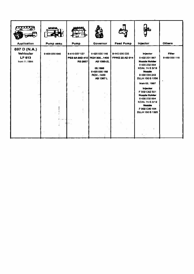
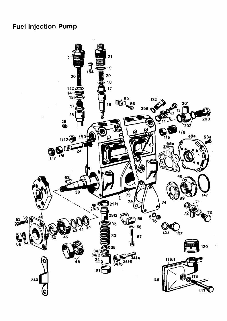

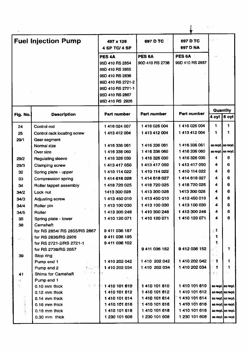

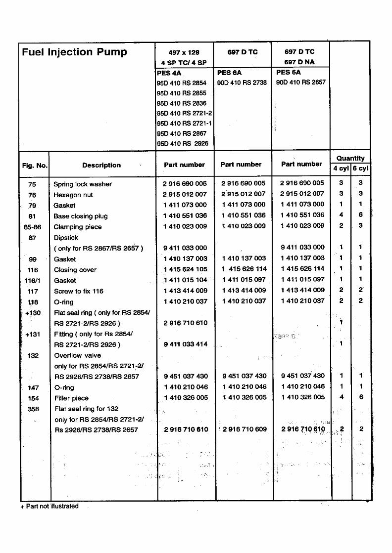

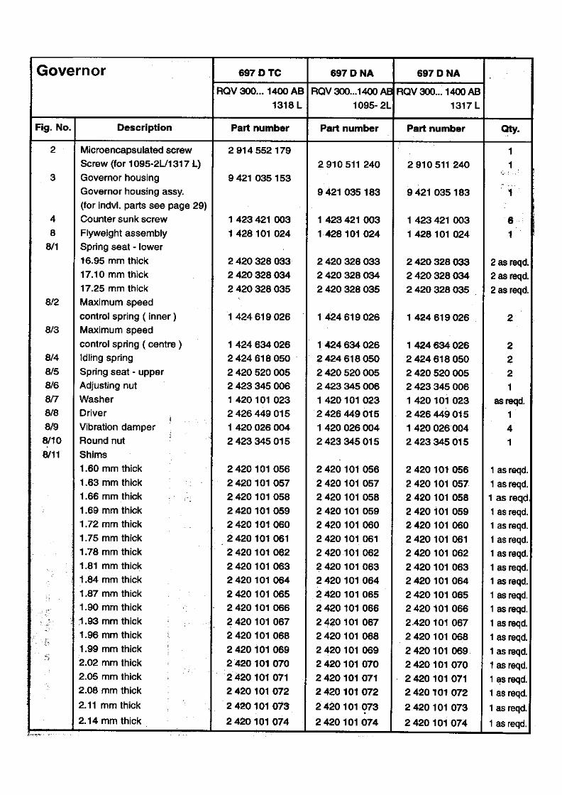
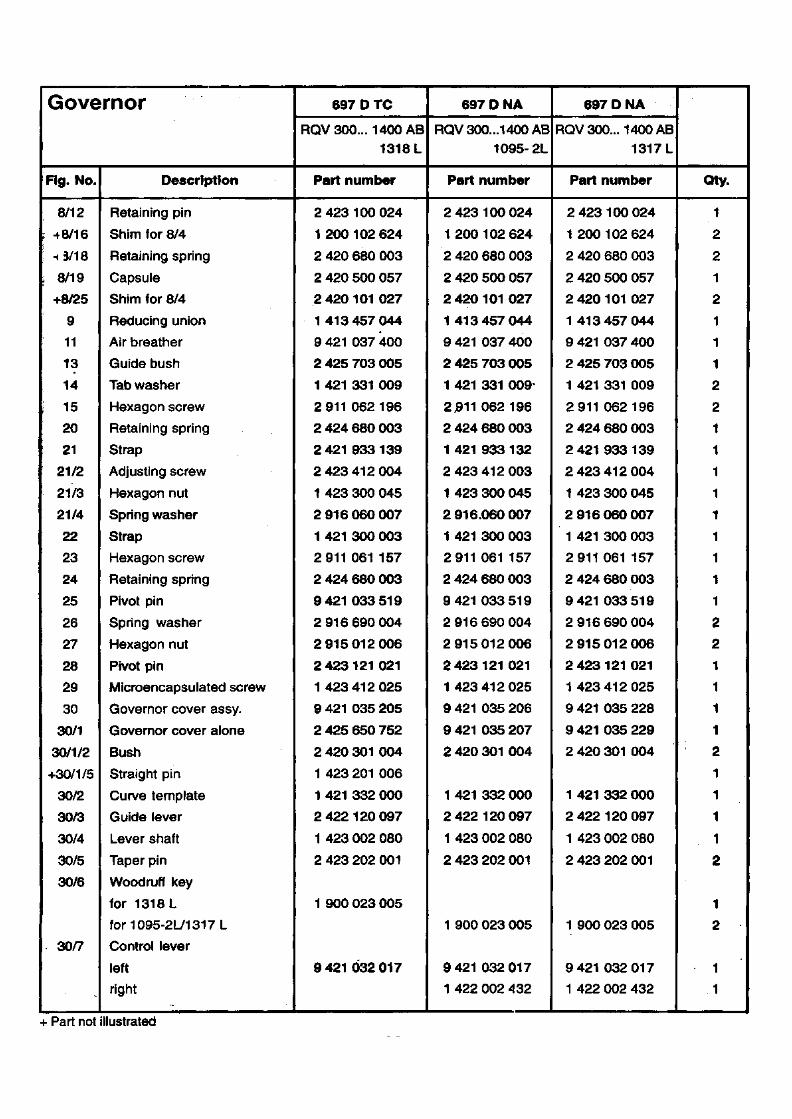

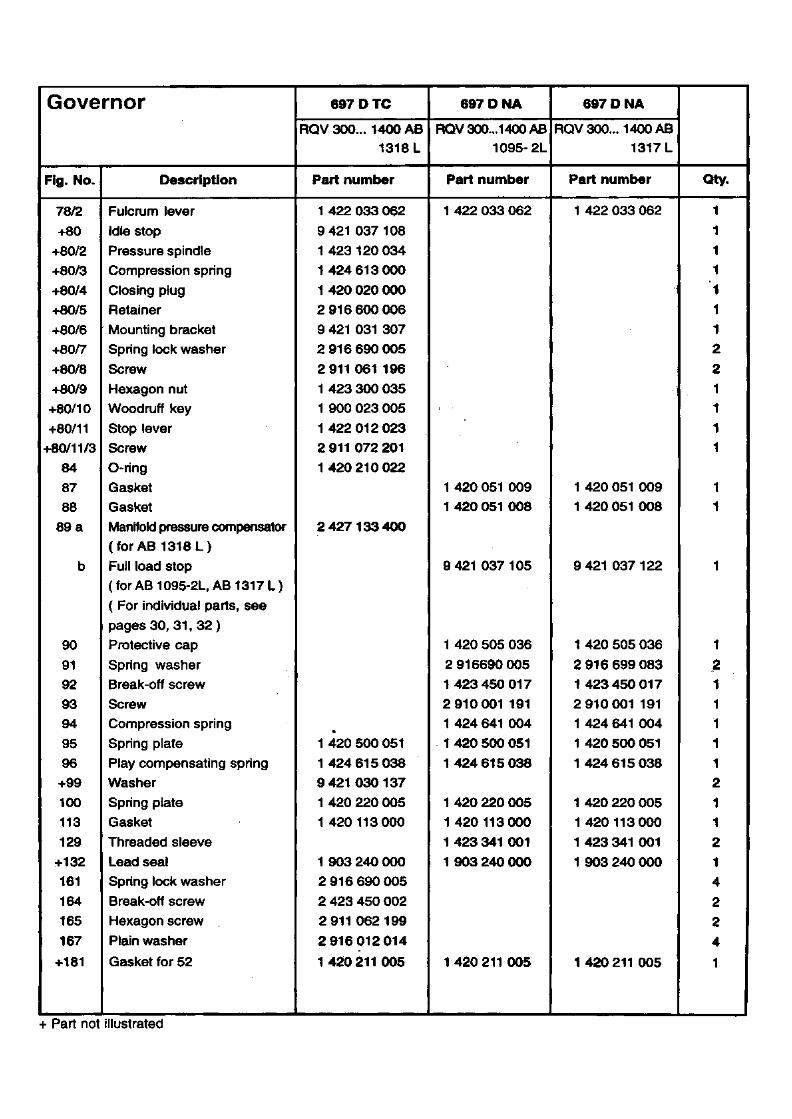
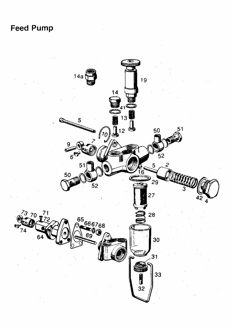
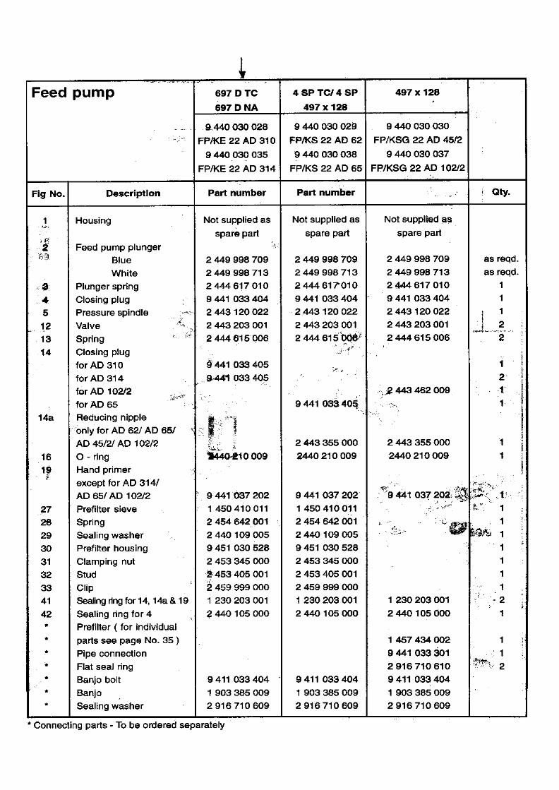
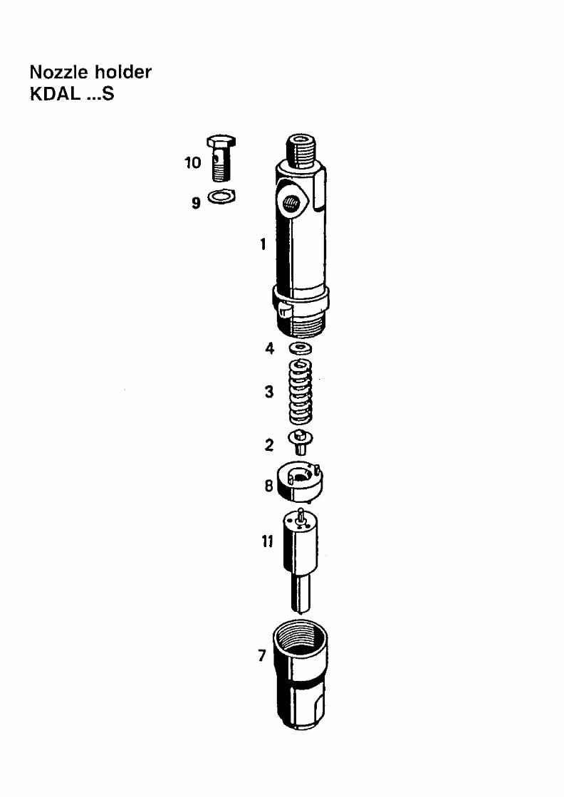
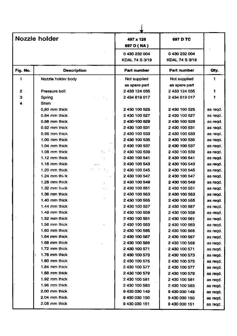
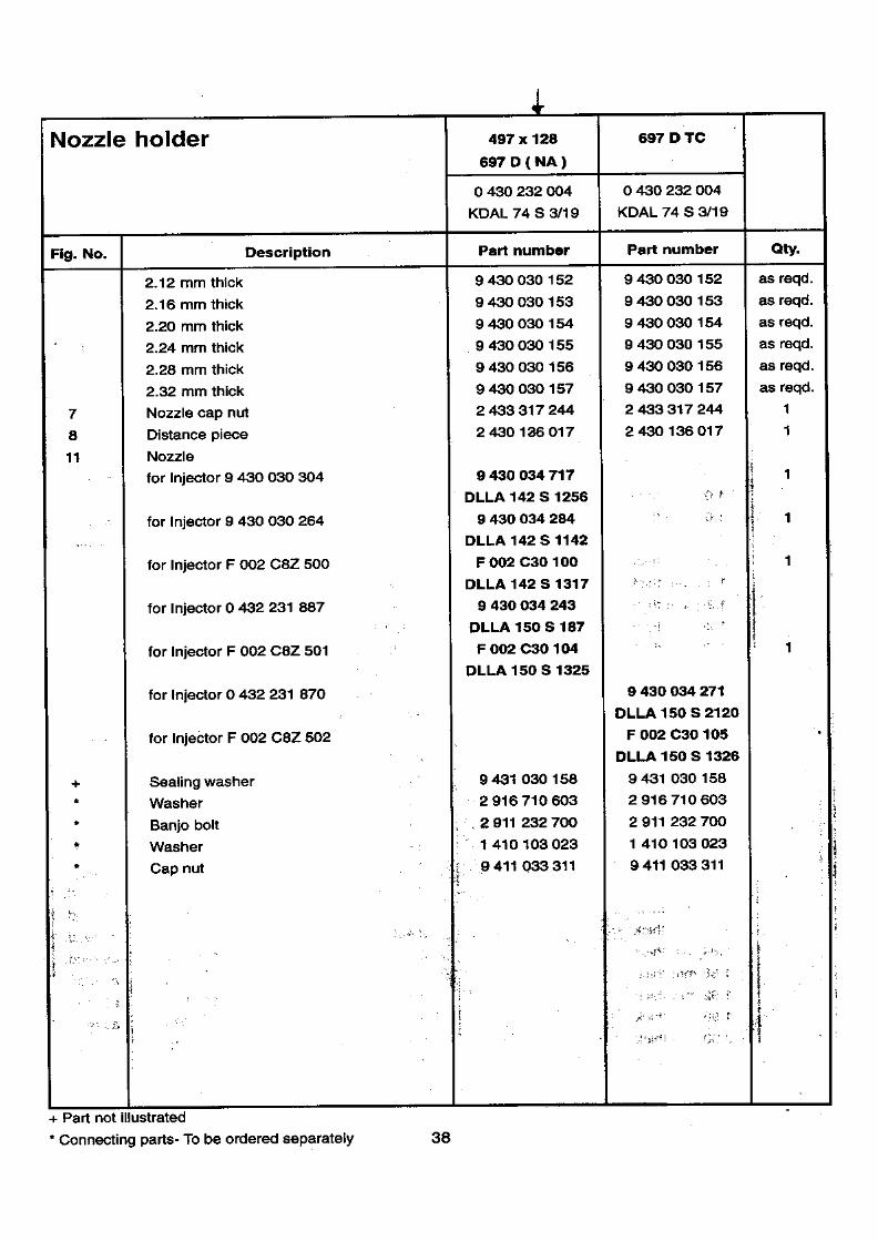
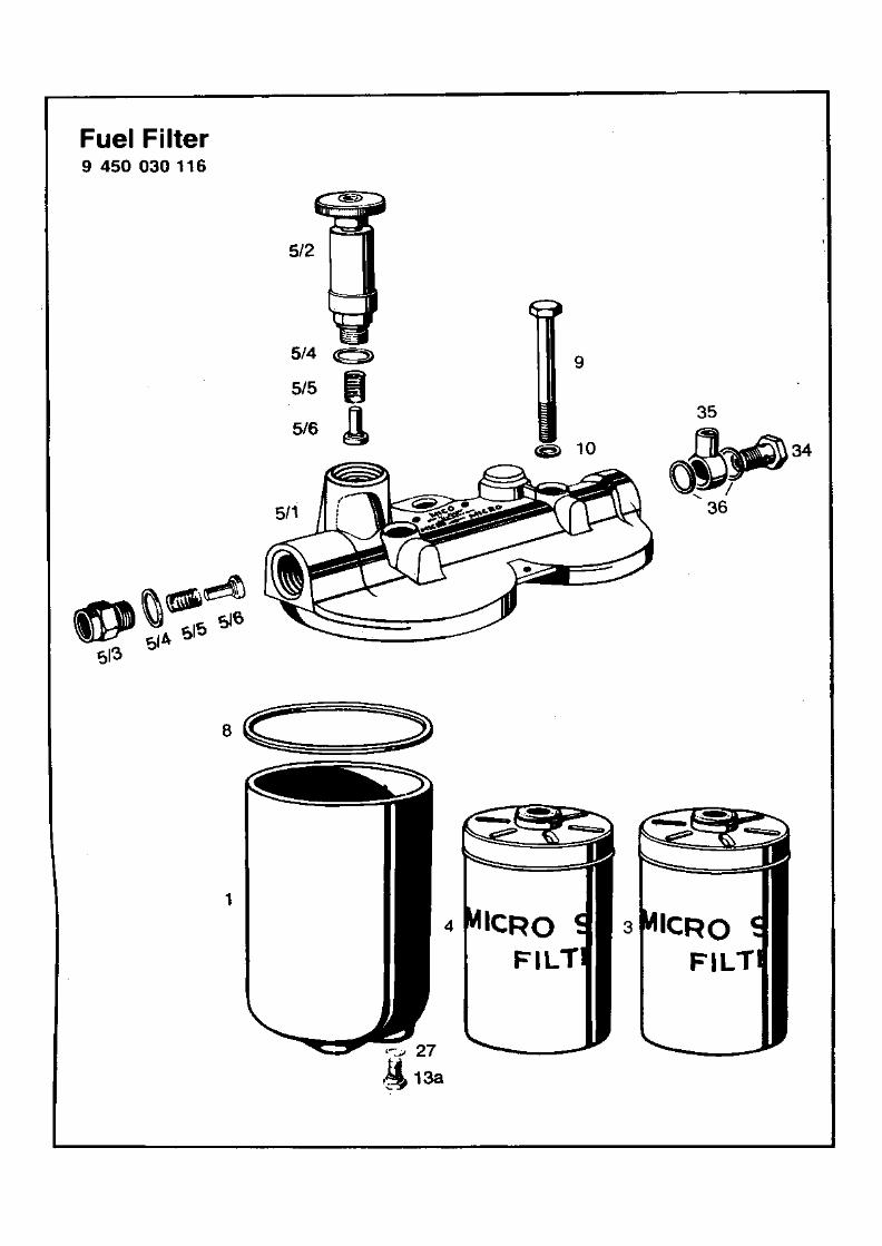
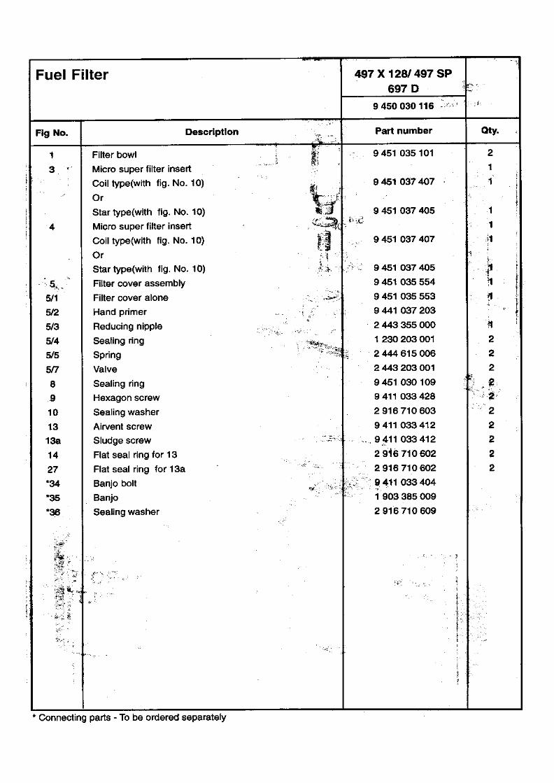
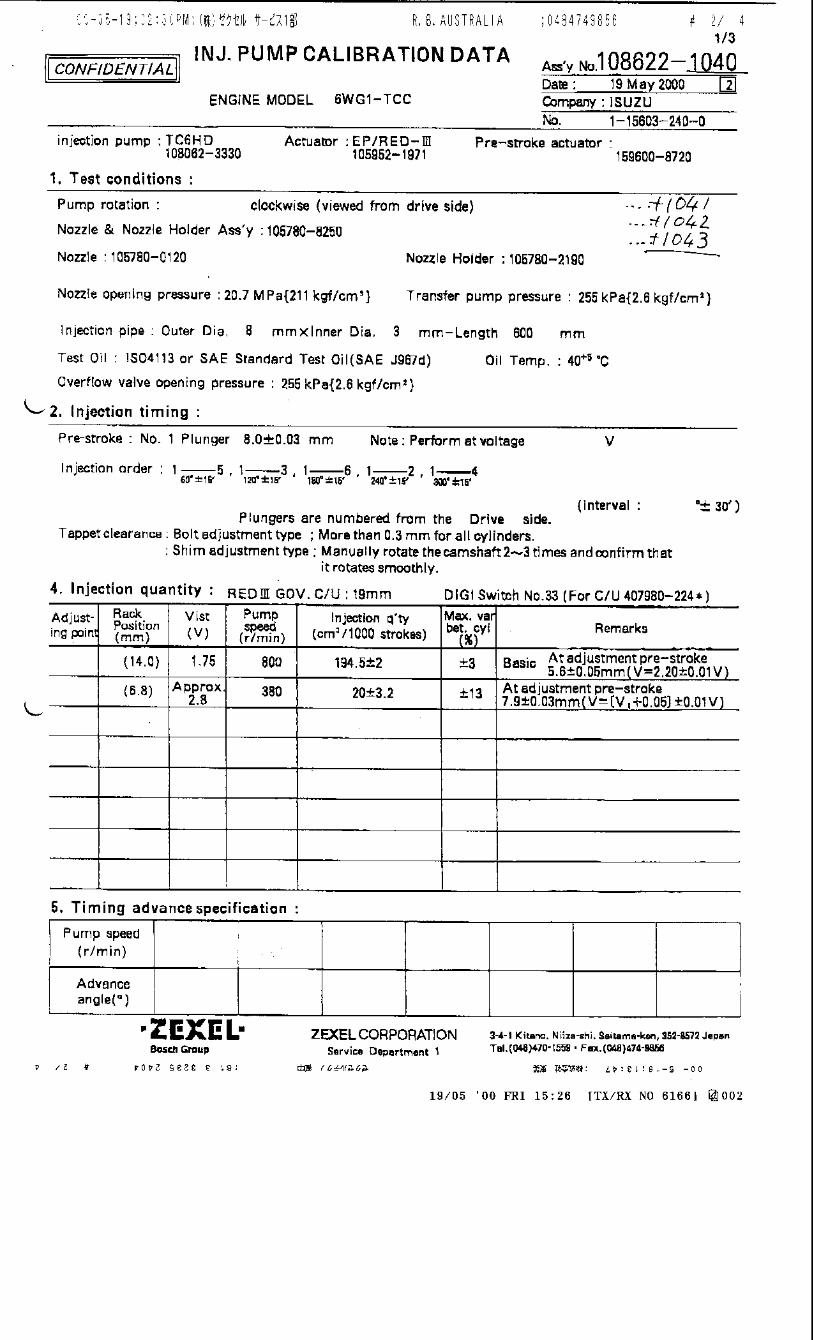
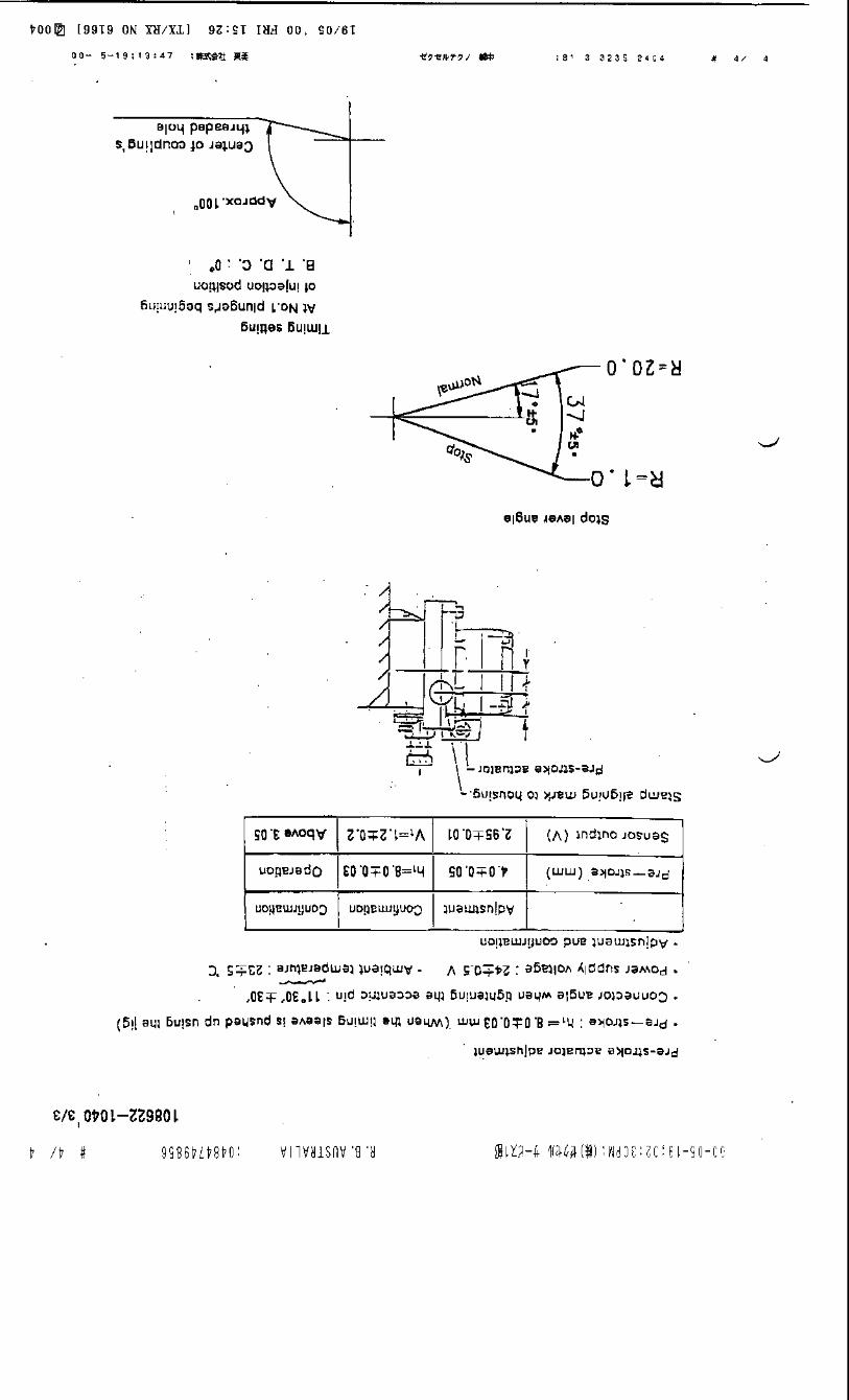
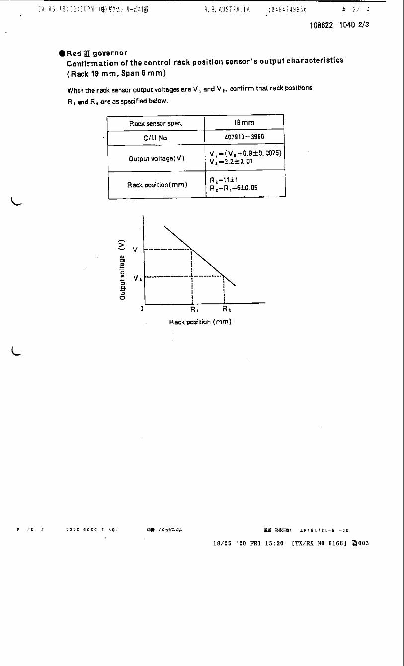

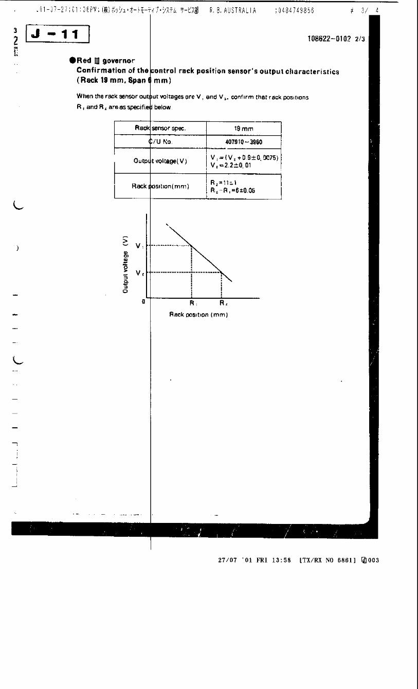
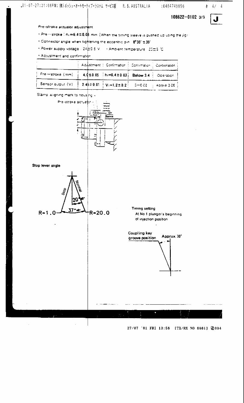
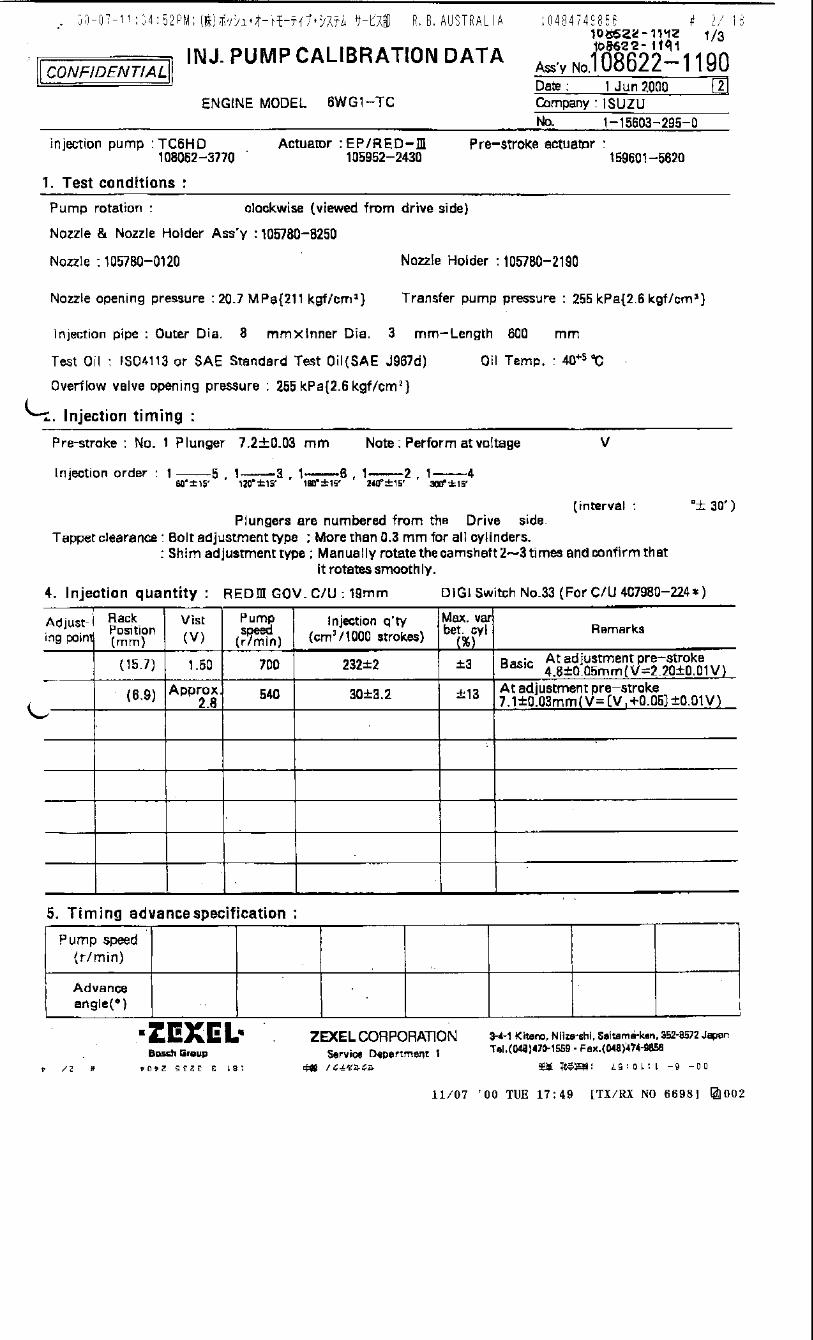
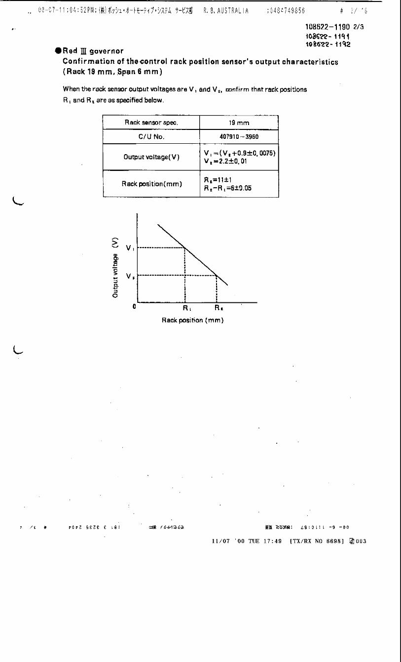
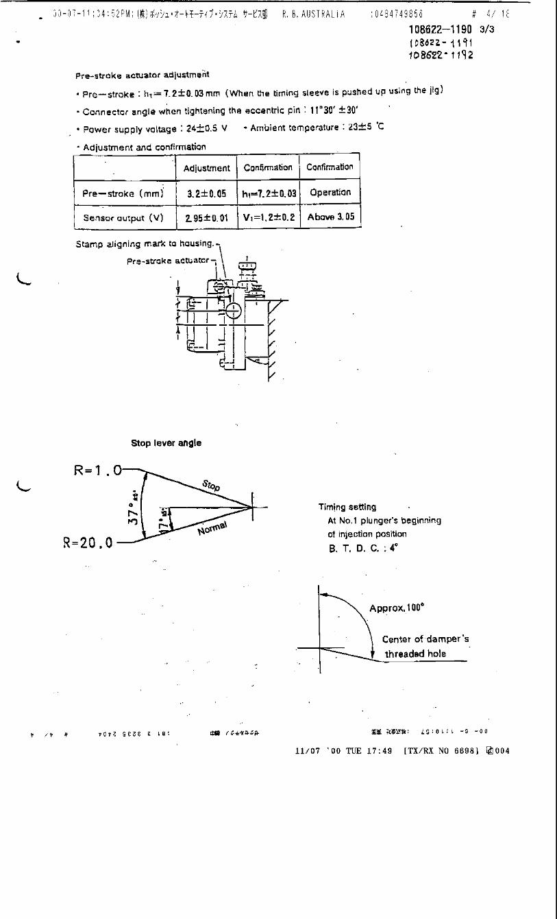
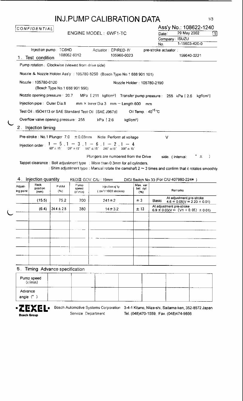
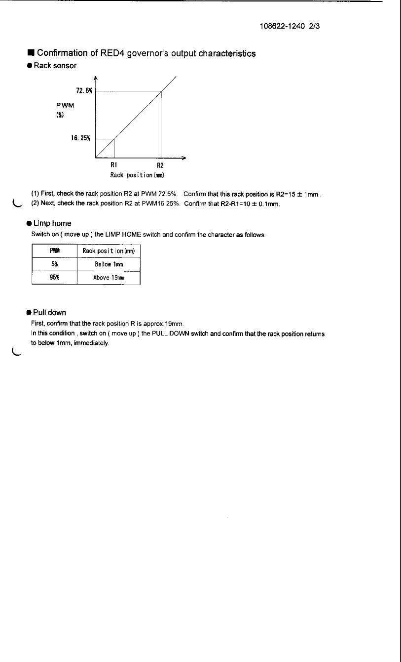
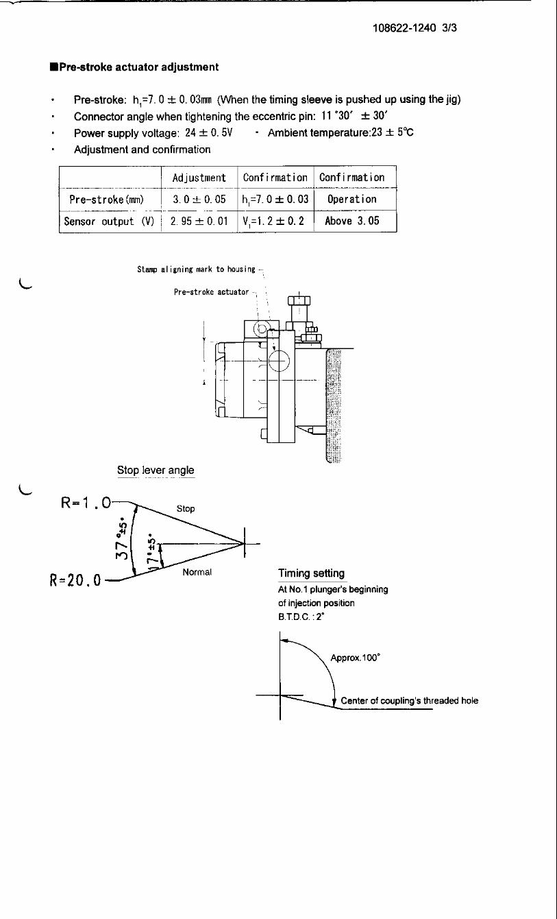

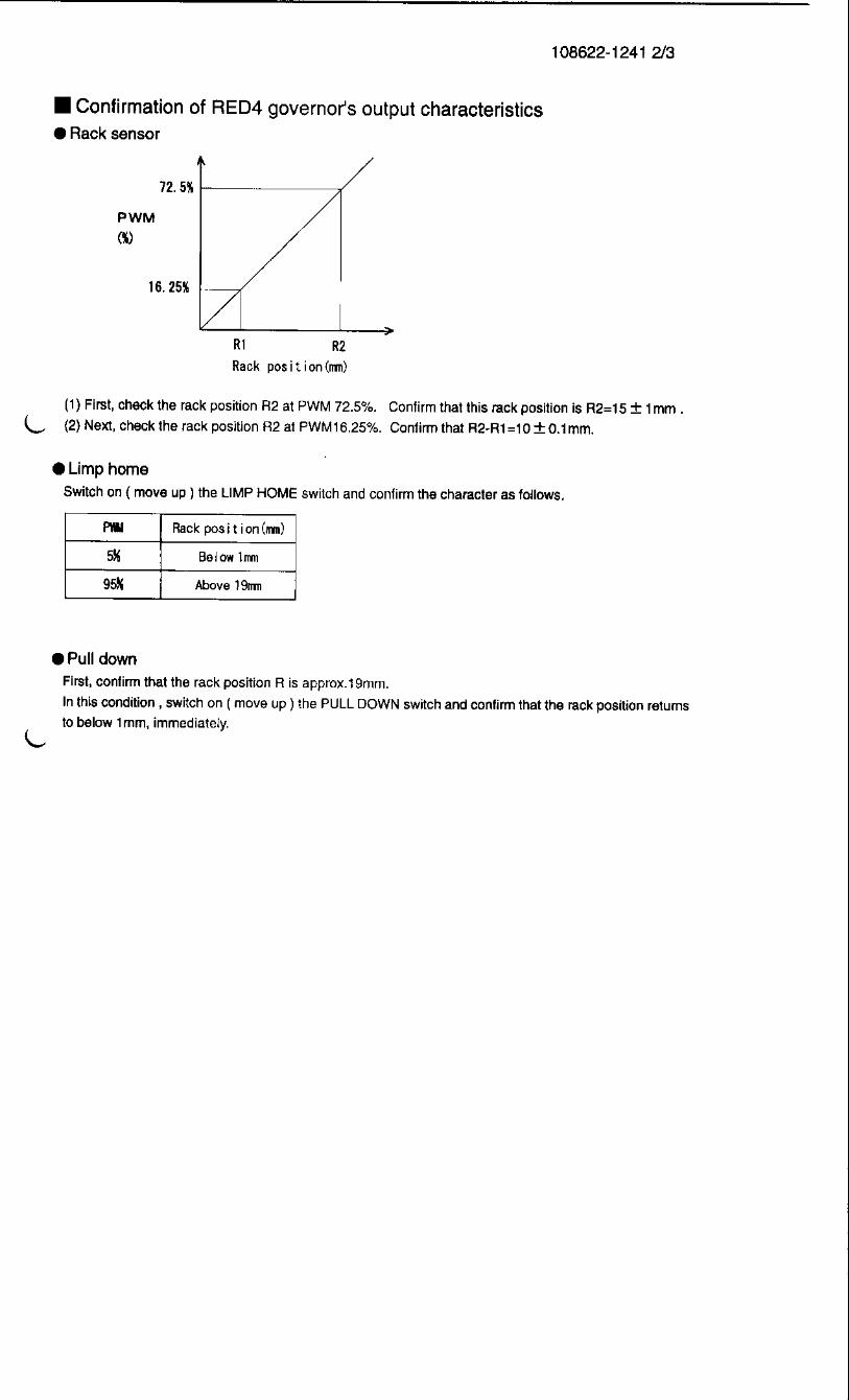


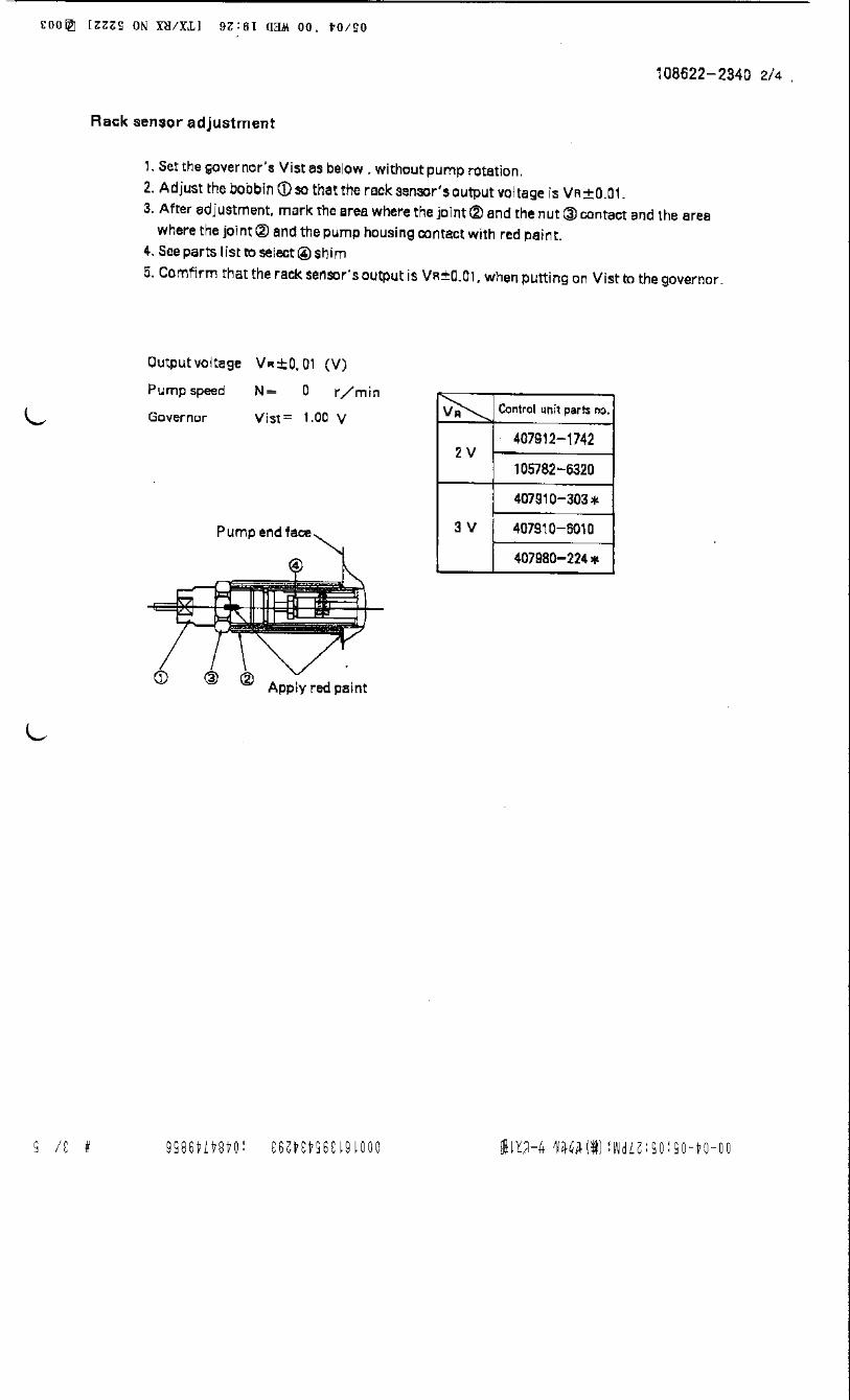
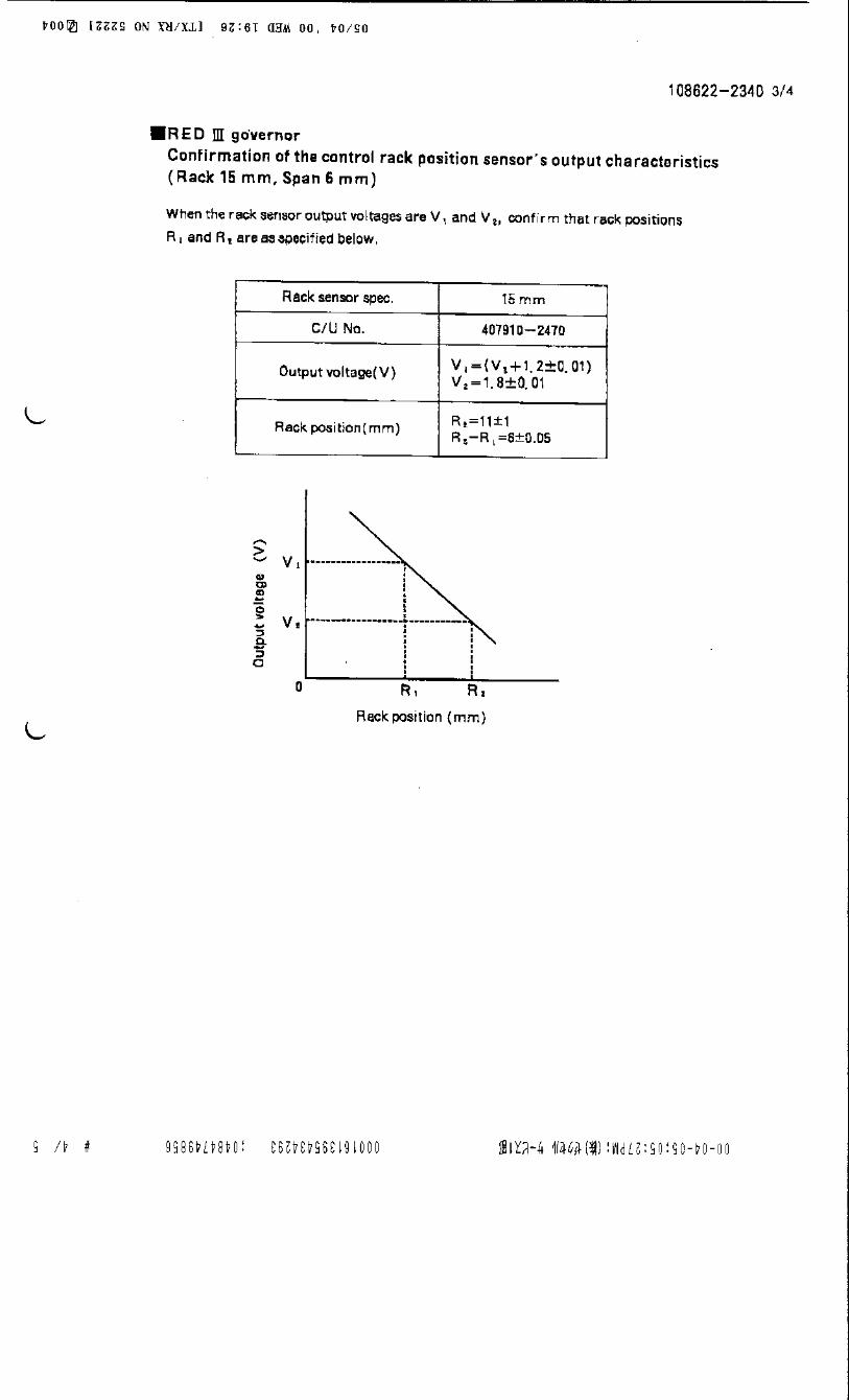

Recommended