SS-ISO 27681-1 m A3,European view placement:
Approved by
1:45
Principal drawingA 5000 - 1100*1467 Shaft drawing
2017-01-04Date sheet
1 of 6Scale:Gen. Tolerances
Order no
151925-W
Tender no
_____________builder:
Chat
1
1
2
2
3
3
4
4
5
5
6
6
A A
B B
C C
D D
Checklist We ask you to verify the information contained on these pages and then return them to us. Returning also attached drawing with any changes.
First, check list before performing installation. 1. Check the specified lifting heights. The lift height is calculated from floor to floor any pit should NOT be counted 2. Shaft wall construction, type of shaft elements (glass, metal) and placement 3. Placement of doors and hanging. 4. Electrical compartment placement (runners and drive are located behind the device instead) 5. Slides should be placed against the wall. Side D per drawing, standing side D against the wall. 6. Vertical mounting points (sized according to plan). Alternatively, 2 standing conventions of figure "attachment on the drawing PIERCING. The attachments must be sized for 250N/1500 mm and shall be + / - 5 mm. Alternatively wall lined with OSB Discs or similar, representing a thrust of 250N/1500 mm. 7. The bottom frame is fastened to the floor with M8x80 screw expander in plate angle shown in Figure "base frame" on the drawing PIERCING 8. Control measure the cutout in the pit. Pit and holes in floors should unwind plumb and perpendicular. The pit must be level smoothed equivalent steel polished concrete. The floor should be painted with dust binding color. 9. If there´s a pit, check the measurement pit depth. 10. Is there underfloor heating in the pit? In that case, where?11. Check cut out the soffit, see drawing "Cut out" 12. Check cut out for door fronts, see drawing "Cut out " 13. Wiring shall be drawn up to lift the lower part as per drawing "electrical" 14. For shaft lighting in ceiling shall separate the power cable be pulled back into the trench upper part, 230 V. (if automatic shaft lighting is ordered,remove it.) 15. Check performance of control buttons to spec platform layout 16. Telephone wire alt GSM module must be installed in the elevator. Purchaser is responsible for an active phone line rental and SIM card (On GSM module) and programming information is received no prior installation of the elevator. 17. NOTE that effective emergency telephone is required for approved inspection. The purchaser is responsible for receiving, unloading and storage of goods, and that there is free passage to the assembly site. 18. Adjusted there any special requirements to get access to the workplace, such as ID06 or SSG, if YES, enter the. Work - 1. Erect scaffolding with fall protection for site built shafts or position at the open shaft or position. At A9000, the opposite trench wall (D-side) incorporate the rule for footbridge.
waste, materials or debris. 4. Stages and transport routes and floor at the site of installation is free of wiring, 3 m height from the top floor. Load requirements 500 kg 3. If there are mounts for attaching game or lifting blocks in the shaft peak of 2.5 to 2. Shaft Openings are provided with guardrails and toe boards.
9. Doorways and passages have sufficient width and height (my 900x2100mm) and to swing additional lighting. 8. Adequate lighting in the place of installation and access to building power for in good and safe condition. 7. If work must be carried out on the roof, the roof the access and safety devices are used are sized and adapted for the work to be performed. 6. If work must be carried out on roofs; requires that scaffolds and work platforms 5. Stored materials at the installation site does not collapse.
14. Running regular activities in the same room as assembly work to be performed, the 13. Coordinate work in the workplace according to AFS 1999:3 12. There is access to the wash basin and toilet 11. There are staff spaces with warmth and ability to heat food and drink. 10. Evacuation routes are marked and free and that there is emergency lighting space in passages of 4.5 meters for long cargo.
client is responsible for the necessary barriers exist.
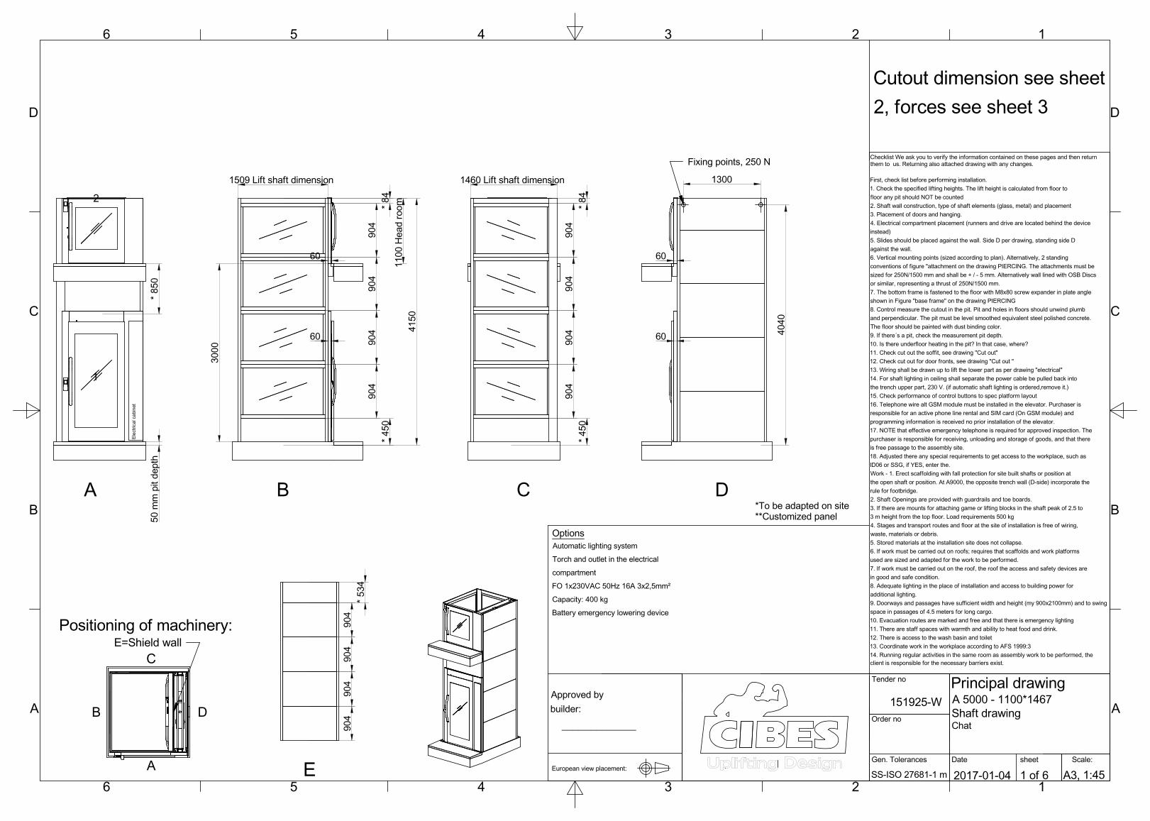
Cutout dimension see sheet 2, forces see sheet 3
*To be adapted on site**Customized panel
Battery emergency lowering device Capacity: 400 kgFO 1x230VAC 50Hz 16A 3x2,5mm²compartment Torch and outlet in the electrical Automatic lighting system Options
Electrical cabine
t
2
A
1
* 850
50 mm pit d
epth
B
60
60
* 450
904
904
904
904
* 84
1509 Lift shaft dimension
4150
1100 Head room
3000
C
* 450
904
904
* 84
904
904
1460 Lift shaft dimension Fixing points, 250 N
D
60
60
1300
4040
E
904
904
904
904
* 534
B
A
E=Shield wall
D
Positioning of machinery:
C
Recommended