XV-Z
15000
XV-Z15000PROJECTORPROJECTEURPROYECTORPROJETOR
Printed in ChinaImprimé en ChineImpreso en ChinaImpresso na ChinaTINS-E012WJZZ09P01-CH-NM
EN
GLIS
HFR
AN
ÇA
ISE
SPA
ÑO
LP
OR
TU
GU
ÊS
OPERATION MANUALMODE D’EMPLOIMANUAL DE MANEJOMANUAL DE OPERAÇÃO
SHARP CORPORATION
XVZ15000_E_US_Hyo1-4.indd 1XVZ15000_E_US_Hyo1-4.indd 1 2008/12/25 15:07:122008/12/25 15:07:12
SPECIAL NOTE FOR USERS IN THE U.K.The mains lead of this product is fi tted with a non-rewireable (moulded) plug incorporating a 10A fuse. Should the fuse need to be replaced, a BSI or ASTA approved BS 1362 fuse marked or and of the same rating as above, which is also indicated on the pin face of the plug, must be used.Always refi t the fuse cover after replacing the fuse. Never use the plug without the fuse cover fi tted.In the unlikely event of the socket outlet in your home not being compatible with the plug supplied, cut off the mains plug and fi t an appropriate type.
DANGER:The fuse from the cut-off plug should be removed and the cut-off plug destroyed immediately and dis-posed of in a safe manner.Under no circumstances should the cut-off plug be inserted elsewhere into a 13A socket outlet, as a serious electric shock may occur.To fi t an appropriate plug to the mains lead, follow the instructions below:
WARNING:THIS APPARATUS MUST BE EARTHED.IMPORTANT:The wires in this mains lead are coloured in accordance with the following code:
Green-and-yellow : EarthBlue : NeutralBrown : Live
As the colours of the wires in the mains lead of this apparatus may not correspond with the coloured markings identifying the terminals in your plug proceed as follows:• The wire which is coloured green-and-yellow must be connected to the terminal in the plug which is
marked by the letter E or by the safety earth symbol or coloured green or green-and-yellow.• The wire which is coloured blue must be connected to the terminal which is marked with the letter N
or coloured black.• The wire which is coloured brown must be connected to the terminal which is marked with the letter L
or coloured red.
IF YOU HAVE ANY DOUBT, CONSULT A QUALIFIED ELECTRICIAN.
XVZ15000_E_US_Hyo1-4.indd 2XVZ15000_E_US_Hyo1-4.indd 2 2008/12/25 15:07:122008/12/25 15:07:12
EN
GLIS
H
-1
Before using the projector, please read this operation manual carefully.
WARNING: To reduce the risk of fi re or electric shock, do not expose this product to rain or mois ture.
WARNING: High brightness light source. Do not stare into the beam of light, or view directly. Be especially
careful that children do not stare directly into the beam of light.
CAUTION: TO REDUCE THE RISK OF ELECTRIC SHOCK,DO NOT REMOVE COVER.
NO USER-SERVICEABLE PARTS EXCEPT LAMP UNIT.REFER SERVICING TO QUALIFIED SERVICE PERSONNEL.
The lightning fl ash with arrowhead sym bol, within an equilateral triangle, is in tended to alert the user to the presence of uninsulated “dangerous voltage” within the product’s enclosure that may be of suffi cient magnitude to constitute a risk or electric shock to persons.
The exclamation point within a triangle is intended to alert the user to the presence of important operating and maintenance (servicing) instructions in the literature accompanying the product.
Introduction
CAUTION
See bottom of projector.
IMPORTANT• For your assistance in reporting the loss or theft of
your Projector, please record the Serial Number lo-cated on the bottom of the projector and retain this information.
• Before recycling the packag ing, please ensure that you have checked the con tents of the carton thor-oughly against the list of “Supplied accessories” on page 8.
Model No.: XV-Z15000
Serial No.:
RISK OF ELECTRIC SHOCK.DO NOT REMOVE SCREWS EXCEPT SPECIFIED USER
SERVICE SCREW.
WARNING: This is a Class A product. In a domestic environment this product may cause radio interference in which case the user may be required to take adequate measures.
XV-Z15000_E_US.indb 1XV-Z15000_E_US.indb 1 2008/12/25 14:25:122008/12/25 14:25:12
-2
Caution Concerning Lamp ReplacementSee “Replacing the Lamp” on page 50.
PRODUCT DISPOSALThis product utilizes tin-lead solder, and lamp containing a small amount of mercury. Disposal of these materials may be regulated due to environmental considerations. For disposal or recycling information, please contact your local authorities, the Electronics Industries Al-liance: www.eiae.org, the lamp recycling organization www.lamprecycle.org, or Sharp at 1-800-BE-SHARP.
U.S.A. ONLYU.S.A. ONLY
This SHARP projector uses a DLP® chip. This very sophisticated panel contains 2,073,600 pixels (micromirrors). As
with any high technology electronic equipment such as large screen TVs, video systems and video cameras, there are certain acceptable tolerances that the equipment must conform to.This unit has some inactive pixels within acceptable tolerances which may result in inactive dots on the picture screen. This will not affect the picture quality or the life expectancy of the unit.
INFORMATIONThis equipment has been tested and found to comply with the limits for a Class B digital device, pursuant to Part 15 of the FCC Rules. These limits are designed to provide reasonable protection against harmful interference in a resi-dential installation. This equipment generates, uses, and can radiate radio frequency energy and, if not installed and used in accordance with the operation manual, may cause harmful interference to radio communications. However, there is no guarantee that interference will not occur in a particular installation. If this equipment does cause harmful interference to radio or television reception, which can be determined by turning the equipment off and on, the user is encouraged to try to correct the interference by one or more of the following measures:• Reorient or relocate the receiving antenna.• Increase the separation between the equipment and the receiver.• Connect the equipment into an outlet on a circuit different from that to which the receiver is connected.• Consult the dealer or an experienced radio/TV technician for help.
Declaration of conformitySHARP PROJECTOR, MODEL XV-Z15000This device complies with Part 15 of the FCC rules. Operation is subject to the following conditions: (1) This device may not cause harmful interference, and (2) this device must accept any interference received, including interference that may cause undesired operation.
Responsible Party:
SHARP ELECTRONICS CORPORATIONSharp Plaza, Mahwah, New Jersey 07495-1163TEL: 1-800-BE-SHARP (1-800-237-4277)
U.S.A. ONLY
U.S.A. ONLY
Authorized representative responsible for the European Union Community Market
SHARP ELECTRONICS (Europe) GmbHSonninstraße 3, D-20097 Hamburg
WARNING: FCC Regulations state that any unauthorized changes or modifi cations to this equipment not ex-pressly approved by the manufacturer could void the user’s authority to operate this equip ment.
U.S.A. ONLYU.S.A. ONLY
E.U. ONLY
XV-Z15000_E_US.indb 2XV-Z15000_E_US.indb 2 2008/12/25 14:25:122008/12/25 14:25:12
Introd
uction
-3
Contents
PreparingSetupSetting Up the Projector ...............................15
Setting Up the Projector ...................................... 15Standard Setup (Front Projection) ........................ 15Projection (PRJ) Mode ......................................... 16Ceiling-mount Setup ........................................... 16Screen Size and Projection Distance ................... 17
ConnectionsSamples of Cables for Connection ..............18Connecting to Video Equipment ..................19Connecting to a Computer ...........................20Controlling the Projector by a Computer ....21
IntroductionContents ...........................................................3How to Read this Operation Manual .............4IMPORTANT SAFEGUARDS............................5Accessories .....................................................8Part Names and Functions .............................9Using the Remote Control ............................12
Inserting the Batteries.......................................... 12Usable Range ..................................................... 12
Quick StartQuick Start .....................................................13
UsingBasic OperationTurning the Projector On/Off ........................22
Connecting the Power Cord ................................ 22Turning the Projector On ..................................... 22Turning the Power Off
(Putting the Projector into Standby Mode) ..... 22
Image Projection ...........................................23Adjusting the Projected Image ............................. 23Keystone Correction ............................................ 24Auto V-Keystone Correction ................................ 25Switching the Input Mode.................................... 26Adjusting the Vertical and Horizontal Position of the Image ... 26Displaying the Black Screen Temporarily ............. 27Freezing a Moving Image..................................... 27Auto Sync (Auto Sync Adjustment) ...................... 27Selecting the Picture Mode ................................. 27Displaying an Enlarged Portion of an Image ......... 28Switching the Iris Setting ..................................... 28Hiding the Menu Temporarily (Menu Hide) ........... 28Switching the Eco+Quiet Mode ........................... 28Resize Mode ....................................................... 29
Useful FeaturesMenu Bar Items .............................................31Using the Menu Screen .................................34
Menu Selections (Adjustments) ........................... 34
Picture Adjustment (“Picture” Menu) ..........36Selecting the Picture Mode ................................. 36Adjusting the Image ............................................ 36Switching the Iris Setting ..................................... 37Eco+Quiet ........................................................... 37Using the Advanced ............................................ 37Correcting Gradation of Video (Gamma Correction) ... 37Adjusting the Colors ............................................ 37Adjusting the Bright Boost ................................... 39
Selecting the Film Mode ...................................... 39Setting Detail Enhancement ................................ 39Reducing Image Noise (DNR) .............................. 39Mosquito Noise Reduction (MNR) ....................... 39Resetting All Adjustment Items ............................ 39
Computer Image Adjustment (“SIG-ADJ” Menu) ...40Adjusting the Computer Image ............................ 40Setting the Resolution ......................................... 40Auto Sync (Auto Sync Adjustment) ...................... 40Signal Type Setting .............................................. 40Setting the Video System .................................... 41Setting the Video Setup....................................... 41Adjusting the Dynamic Range ............................. 41Signal Info ........................................................... 41
Adjusting the Projected Image (“SCR-ADJ” Menu) ...42Setting the Resize Mode ..................................... 42Adjusting the Image Position ............................... 42Adjusting the Overscan ....................................... 42Auto V-Keystone Correction ................................ 43Keystone Mode Correction .................................. 43Setting On-screen Display ................................... 44Setting the Brightness of the Menu Screen .......... 44Selecting the Background Image ......................... 44Selecting the Menu Screen Position .................... 44Reversing/Inverting Projected Images .................. 44Selecting the On-screen Display Language ......... 44
Adjusting the Projector Function (“PRJ-ADJ” Menu) ...45Setting Auto Power Off Mode .............................. 45Setting the Power Save Mode (Economy Mode) ... 45Setting One Touch Play, System Standby
and Input Name ............................................ 45Setting the Demo Mode ....................................... 46Selecting the Transmission Speed (RS-232C) ...... 46Fan Mode Setting ................................................ 46Returning the Default Settings ............................. 46Lamp Timer (Life) ................................................ 46
ReferenceAppendixMaintenance ..................................................47Maintenance Indicators ................................48Regarding the Lamp ......................................50
Lamp .................................................................. 50Caution Concerning the Lamp............................. 50Replacing the Lamp ............................................ 50Removing and Installing the Lamp Unit ................ 51Resetting the Lamp Timer ................................... 52
Connecting Pin Assignments .......................53RS-232C Specifi cations and Commands ....54Computer Compatibility Chart .....................57Troubleshooting .............................................58For SHARP Assistance ..................................60Specifi cations ................................................61Dimensions ....................................................62Index ...............................................................63
XV-Z15000_E_US.indb 3XV-Z15000_E_US.indb 3 2008/12/25 14:25:132008/12/25 14:25:13
-4
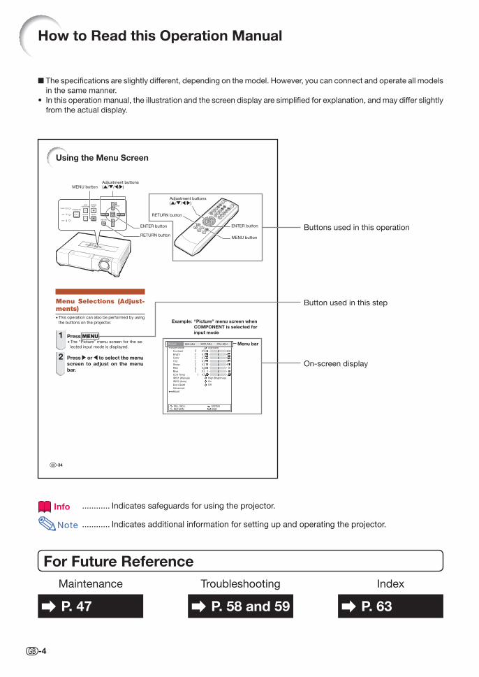
How to Read this Operation Manual
The specifi cations are slightly different, depending on the model. However, you can connect and operate all models
in the same manner.
In this operation manual, the illustration and the screen display are simplifi ed for explanation, and may differ slightly
from the actual display.
■
•
For Future ReferenceMaintenance
P. 47
Troubleshooting
P. 58 and 59
Index
P. 63
Buttons used in this operation
Info ............ Indicates safeguards for using the projector.
Note ............ Indicates additional information for setting up and operating the projector.
-34
Picture
Picture Mode Standard
High Brightness
On
Off
Contrast
Bright
Color
Tint
Sharp
Red
Blue
CLR Temp
IRIS1 (Manual)
IRIS2 (Auto)
Eco+Quiet
Advanced
Reset
SEL./ADJ.RETURN
ENTEREND
SIG-ADJ SCR-ADJ PRJ-ADJ
0
0
0
0
0
0
0
0
Using the Menu Screen
Menu Selections (Adjust-ments)• This operation can also be performed by using
the buttons on the projector.
1 Press MENU.• The “Picture” menu screen for the se-
lected input mode is displayed.
2 Press or to select the menu screen to adjust on the menu bar.
Example: “Picture” menu screen when COMPONENT is selected for input mode
RETURN button
Adjustment buttons( / / / )
ENTER button
MENU button
Adjustment buttons( / / / )
Menu bar
ENTER button
RETURN button
MENU button
Button used in this step
On-screen display
XV-Z15000_E_US.indb 4XV-Z15000_E_US.indb 4 2008/12/25 14:25:132008/12/25 14:25:13
Introd
uction
-5
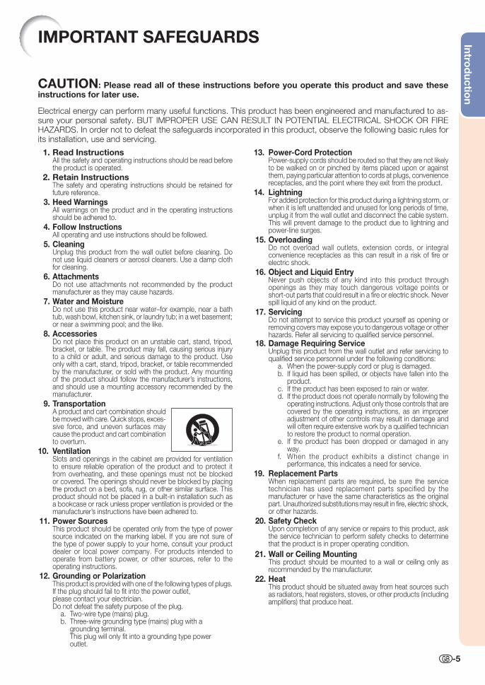
1. Read InstructionsAll the safety and operating instructions should be read before the product is operated.
2. Retain InstructionsThe safety and operating instructions should be retained for future reference.
3. Heed WarningsAll warnings on the product and in the operating instructions should be adhered to.
4. Follow InstructionsAll operating and use instructions should be followed.
5. CleaningUnplug this product from the wall outlet before cleaning. Do not use liquid cleaners or aerosol cleaners. Use a damp cloth for cleaning.
6. AttachmentsDo not use attachments not recommended by the product manufacturer as they may cause hazards.
7. Water and MoistureDo not use this product near water–for example, near a bath tub, wash bowl, kitchen sink, or laundry tub; in a wet basement; or near a swimming pool; and the like.
8. AccessoriesDo not place this product on an unstable cart, stand, tripod, bracket, or table. The product may fall, causing serious injury to a child or adult, and serious damage to the product. Use only with a cart, stand, tripod, bracket, or table recommended by the manufacturer, or sold with the product. Any mounting of the product should follow the manufacturer’s instructions, and should use a mounting accessory recom mended by the manufacturer.
9. TransportationA product and cart combination should be moved with care. Quick stops, exces-sive force, and uneven surfaces may cause the product and cart combination to overturn.
10. VentilationSlots and openings in the cabinet are provided for ventilation to ensure reliable operation of the product and to protect it from overheating, and these openings must not be blocked or covered. The open ings should never be blocked by placing the product on a bed, sofa, rug, or other similar surface. This prod uct should not be placed in a built-in installation such as a book case or rack unless proper ventilation is provided or the manufacturer’s in struc tions have been adhered to.
11. Power SourcesThis product should be operated only from the type of power source indicated on the marking label. If you are not sure of the type of power supply to your home, consult your product dealer or local power com pany. For products intended to operate from battery power, or other sources, refer to the operating instructions.
12. Grounding or PolarizationThis product is provided with one of the following types of plugs. If the plug should fail to fi t into the power outlet,please contact your electrician.Do not defeat the safety purpose of the plug. a. Two-wire type (mains) plug. b. Three-wire grounding type (mains) plug with a grounding terminal. This plug will only fi t into a grounding type power outlet.
IMPORTANT SAFEGUARDS
13. Power-Cord ProtectionPower-supply cords should be routed so that they are not likely to be walked on or pinched by items placed upon or against them, paying particular attention to cords at plugs, convenience receptacles, and the point where they exit from the product.
14. LightningFor added protection for this product during a lightning storm, or when it is left unattended and unused for long periods of time, unplug it from the wall outlet and disconnect the cable system. This will pre vent damage to the product due to lightning and power-line surges.
15. OverloadingDo not overload wall outlets, extension cords, or integral convenience receptacles as this can result in a risk of fi re or electric shock.
16. Object and Liquid EntryNever push objects of any kind into this product through openings as they may touch dangerous voltage points or short-out parts that could result in a fi re or electric shock. Never spill liquid of any kind on the product.
17. ServicingDo not attempt to service this product yourself as opening or removing covers may expose you to dan ger ous voltage or other hazards. Refer all servicing to qualifi ed service personnel.
18. Damage Requiring ServiceUnplug this product from the wall outlet and refer servicing to qualifi ed service person nel under the following conditions:
a. When the power-supply cord or plug is damaged.b. If liquid has been spilled, or objects have fallen into the
product.c. If the product has been exposed to rain or water.d. If the product does not operate normally by following the
operating instructions. Adjust only those con trols that are covered by the operating instructions, as an improper adjustment of other controls may result in damage and will often require extensive work by a qualifi ed technician to restore the product to normal operation.
e. If the product has been dropped or damaged in any way.
f. When the product exhibits a distinct change in performance, this indicates a need for service.
19. Replacement PartsWhen replacement parts are required, be sure the service technician has used replace ment parts specified by the manufacturer or have the same characteristics as the original part. Unauthorized substitutions may result in fi re, electric shock, or other hazards.
20. Safety CheckUpon completion of any service or repairs to this product, ask the service technician to per form safety checks to determine that the product is in proper operating condition.
21. Wall or Ceiling MountingThis product should be mounted to a wall or ceiling only as recommended by the manu facturer.
22. HeatThis product should be situated away from heat sources such as radiators, heat registers, stoves, or other products (including amplifi ers) that produce heat.
CAUTION: Please read all of these instructions before you operate this product and save these instructions for later use.
Electrical energy can perform many useful functions. This product has been engineered and manufactured to as-sure your personal safety. BUT IMPROPER USE CAN RESULT IN POTENTIAL ELECTRICAL SHOCK OR FIRE HAZARDS. In order not to defeat the safeguards incorporated in this product, observe the following basic rules for its installation, use and servicing.
XV-Z15000_E_US.indb 5XV-Z15000_E_US.indb 5 2008/12/25 14:25:142008/12/25 14:25:14
-6
Caution concerning the lamp unit■ Potential hazard of glass particles
if lamp ruptures. In case of lamp
rupture, contact your nearest Sharp
Authorized Projector Dealer or Service
Center for replacement.
See “Regarding the Lamp” on page
50.
Caution concerning the setup of the projector■ For minimal servicing and to maintain high image quality,
SHARP recommends that this projector be installed in
an area free from humidity, dust and cigarette smoke.
When the projector is subjected to these environments,
the vents and lens must be cleaned more often. As
long as the projector is regularly cleaned, use in these
environments will not reduce the overall operation life of
the unit. Internal cleaning should only be performed by
a Sharp Authorized Projector Dealer or Service Center.
Do not set up the projector in places exposed to direct sunlight or bright light.■ Position the screen so that it is not in direct sunlight or
room light. Light falling directly on the screen washes out
the colors, making viewing diffi cult. Close the curtains
and dim the lights when setting up the screen in a sunny
or bright room.
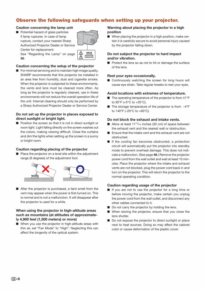
Caution regarding placing of the projector■ Place the projector on a level site within the adjustment
range (9 degrees) of the adjustment foot.
■ After the projector is purchased, a faint smell from the
vent may appear when the power is fi rst turned on. This
is normal and is not a malfunction. It will disappear after
the projector is used for a while.
When using the projector in high-altitude areas such as mountains (at altitudes of approximate-ly 4,900 feet (1,500 meters) or more)■ When you use the projector in high-altitude areas with
thin air, set “Fan Mode” to “High”. Neglecting this can
affect the longevity of the optical system.
Warning about placing the projector in a high position■ When placing the projector in a high position, make cer-
tain it is carefully secure to avoid personal injury caused
by the projector falling down.
Do not subject the projector to hard impact and/or vibration.■ Protect the lens so as not to hit or damage the surface
of the lens.
Rest your eyes occasionally.■ Continuously watching the screen for long hours will
cause eye strain. Take regular breaks to rest your eyes.
Avoid locations with extremes of temperature.■ The operating temperature of the projector is from 41°F
to 95°F (+5°C to +35°C).
■ The storage temperature of the projector is from –4°F
to 140°F (–20°C to +60°C).
Do not block the exhaust and intake vents.■ Allow at least 1113/16 inches (30 cm) of space between
the exhaust vent and the nearest wall or obstruction.
■ Ensure that the intake vent and the exhaust vent are not
obstructed.
■ If the cooling fan becomes obstructed, a protection
circuit will automatically put the projector into standby
mode to prevent overheat damage. This does not indi-
cate a malfunction. (See page 48.) Remove the projector
power cord from the wall outlet and wait at least 10 min-
utes. Place the projector where the intake and exhaust
vents are not blocked, plug the power cord back in and
turn on the projector. This will return the projector to the
normal operating condition.
Caution regarding usage of the projector■ If you are not to use the projector for a long time or
before moving the projector, make certain you unplug
the power cord from the wall outlet, and disconnect any
other cables connected to it.
■ Do not carry the projector by holding the lens.
■ When storing the projector, ensure that you close the
lens shutter.
■ Do not expose the projector to direct sunlight or place
next to heat sources. Doing so may affect the cabinet
color or cause deformation of the plastic cover.
Observe the following safeguards when setting up your projector.
XV-Z15000_E_US.indb 6XV-Z15000_E_US.indb 6 2008/12/25 14:25:142008/12/25 14:25:14
Introd
uction
-7
Other connected equipment■ When connecting a computer or other audio-visual
equipment to the projector, make the connections AFTER
unplugging the power cord of the projector from the AC
outlet and turning off the equipment to be connected.
■ Please read the operation manuals of the projector and
the equipment to be connected for instructions on how
to make the connections.
Using the projector in other countries■ The power supply voltage and the shape of the plug may
vary depending on the region or country you are using the
projector in. When using the projector overseas, make
sure you use an appropriate power cord for the country
you are in.
Temperature monitor function
■ If the temperature inside the projector increases, due
to blockage of the air vents, or the setting location,
the temperature warning indicator will blink. And if the
temperature keeps on rising, “ ” will illuminate in
the lower left corner of the picture with the temperature
warning indicator blinking. If this state continues, the
lamp will turn off, the cooling fan will run and then the
projector will enter standby mode. Refer to “Maintenance
Indicators” on pages 48 and 49 for details.
Info
• The cooling fan regulates the internal temperature,
and its performance is automatically controlled.
The sound of the fan may change during projector
operation due to changes in the fan speed. This
does not indicate malfunction.
The DLP® logo and the DLP
® medallion are registered trade marks of Texas Instruments.
Microsoft® and Windows
® are registered trade marks of Microsoft Corporation in the Unit ed States and/or other
countries.
PC/AT is a registered trademark of In ter na tion al Business Ma chines Cor po ra tion in the United States.
Macintosh® is a registered trademark of Apple Computer, Inc. in the United States and/or other countries.
HDMI, the HDMI logo and High-Defi nition Multimedia Interface are trademarks or reg is tered trademarks of
HDMI Licensing LLC.
All other company or product names are trademarks or registered trademarks of their re spec tive companies.
Some IC chips in this product include confi dential and/or trade secret property belonging to Texas Instru-
ments. Therefore you may not copy, modify, adapt, translate, distribute, reverse engineer, reverse assemble or
discompile the contents thereof.
•
•
•
•
•
•
•
XV-Z15000_E_US.indb 7XV-Z15000_E_US.indb 7 2008/12/25 14:25:142008/12/25 14:25:14
-8
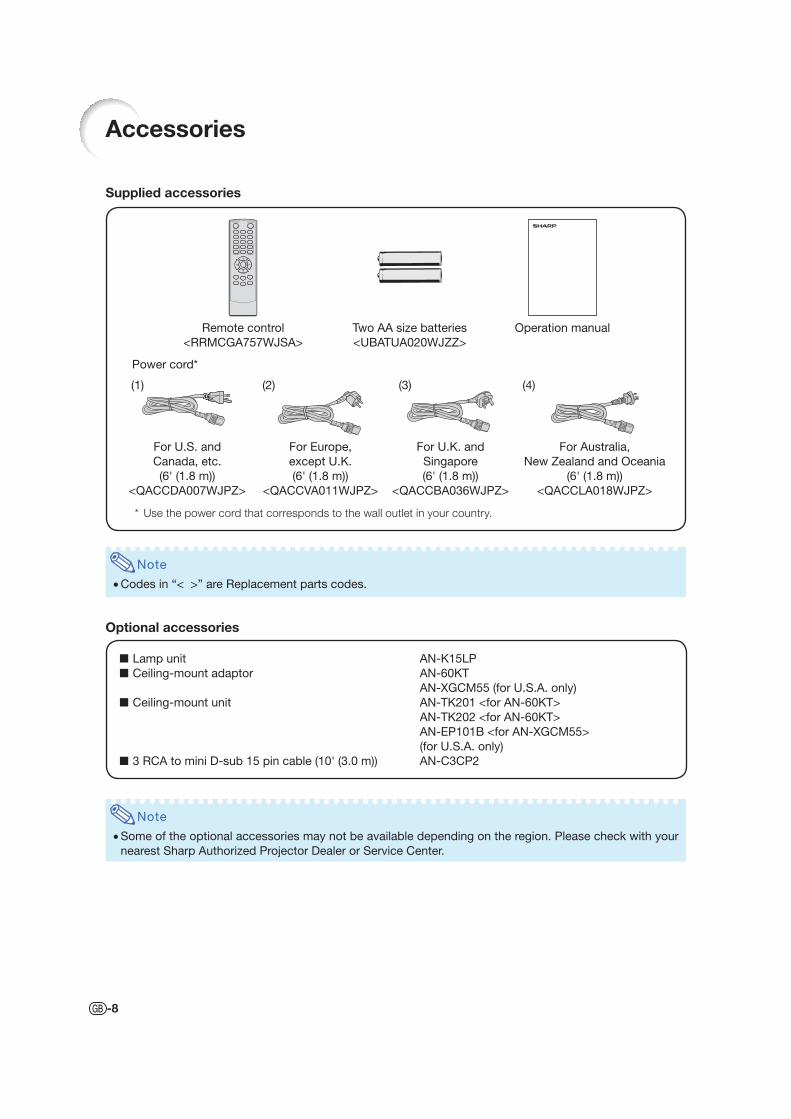
Accessories
Supplied accessories
Lamp unit AN-K15LP
Ceiling-mount adaptor AN-60KT
AN-XGCM55 (for U.S.A. only)
Ceiling-mount unit AN-TK201 <for AN-60KT>
AN-TK202 <for AN-60KT>
AN-EP101B <for AN-XGCM55>
(for U.S.A. only)
3 RCA to mini D-sub 15 pin cable (10' (3.0 m)) AN-C3CP2
■
■
■
■
Two AA size batteries
<UBATUA020WJZZ>
Remote control
<RRMCGA757WJSA>
Note
Some of the optional accessories may not be available depending on the region. Please check with your
nearest Sharp Authorized Projector Dealer or Service Center.
Note
Codes in “< >” are Replacement parts codes.
Optional accessories
Power cord*
For U.S. and
Canada, etc.
(6' (1.8 m))
<QACCDA007WJPZ>
(1)
* Use the power cord that corresponds to the wall outlet in your country.
(2)
For Europe,
except U.K.
(6' (1.8 m))
<QACCVA011WJPZ>
(3)
For U.K. and
Singapore
(6' (1.8 m))
<QACCBA036WJPZ>
(4)
For Australia,
New Zealand and Oceania
(6' (1.8 m))
<QACCLA018WJPZ>
Operation manual
Introd
uction
-9
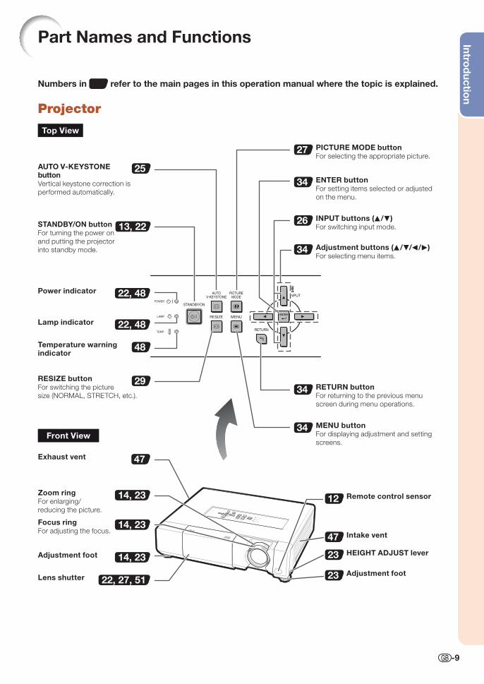
Numbers in refer to the main pages in this operation manual where the topic is explained.
Projector
Part Names and Functions
47
25
22, 48
13, 22
22, 48
22, 27, 51
14, 23
14, 23
14, 23
34
26
34
48
34
34
29
27
12
47
23
23
STANDBY/ON buttonFor turning the power on
and putting the projector
into standby mode.
Lamp indicator
Temperature warning indicator
Adjustment buttons (P/R/O/Q)For selecting menu items.
ENTER buttonFor setting items selected or adjusted
on the menu.
MENU buttonFor displaying adjustment and setting
screens.
Focus ringFor adjusting the focus.
INPUT buttons (P/R)For switching input mode.
Remote control sensor
HEIGHT ADJUST lever
PICTURE MODE buttonFor selecting the appropriate picture.
Intake vent
Zoom ringFor enlarging/
reducing the picture.
RESIZE buttonFor switching the picture
size (NORMAL, STRETCH, etc.).
Power indicator
Adjustment foot
Lens shutter
RETURN buttonFor returning to the previous menu
screen during menu operations.
Adjustment foot
AUTO V-KEYSTONE buttonVertical keystone correction is
performed automatically.
Top View
Front View
Exhaust vent
XV-Z15000_E_US.indb 9XV-Z15000_E_US.indb 9 2008/12/25 14:25:162008/12/25 14:25:16
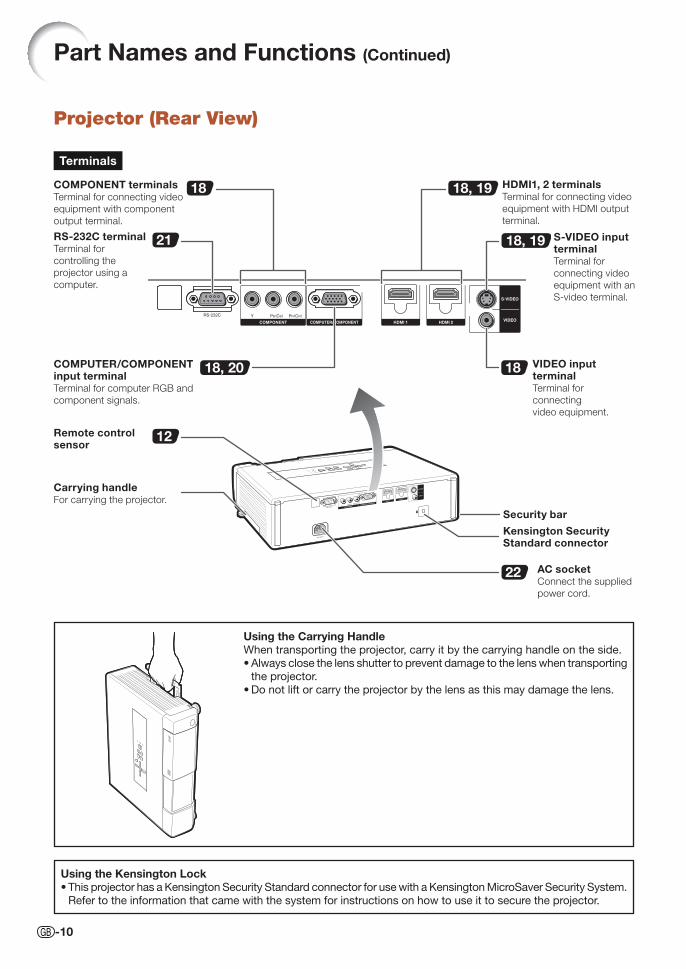
-10
Projector (Rear View)
Using the Kensington LockThis projector has a Kensington Security Standard connector for use with a Kensington MicroSaver Security System.
Refer to the information that came with the system for instructions on how to use it to secure the projector.
•
21
18
18
12
22
18, 19
18, 19
18, 20
COMPONENT terminalsTerminal for connecting video
equipment with component
output terminal.
HDMI1, 2 terminalsTerminal for connecting video
equipment with HDMI output
terminal.
RS-232C terminalTerminal for
controlling the
projector using a
computer.
COMPUTER/COMPONENT input terminalTerminal for computer RGB and
component signals.
S-VIDEO input terminalTerminal for
connecting video
equipment with an
S-video terminal.
VIDEO input terminalTerminal for
connecting
video equipment.
Kensington Security Standard connector
Remote control sensor
Security bar
Terminals
Part Names and Functions (Continued)
Carrying handleFor carrying the projector.
AC socketConnect the supplied
power cord.
Using the Carrying HandleWhen transporting the projector, carry it by the carrying handle on the side.
Always close the lens shutter to prevent damage to the lens when transporting
the projector.
Do not lift or carry the projector by the lens as this may damage the lens.
•
•
XV-Z15000_E_US.indb 10XV-Z15000_E_US.indb 10 2008/12/25 14:25:162008/12/25 14:25:16
Introd
uction
-11
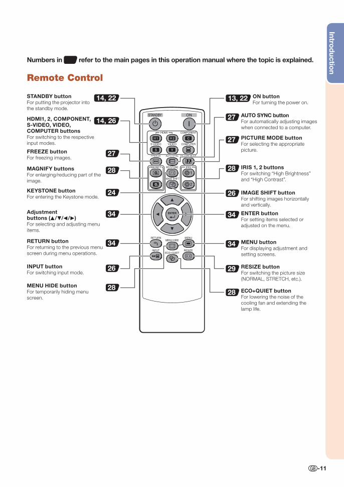
Numbers in refer to the main pages in this operation manual where the topic is explained.
Remote Control
STANDBY buttonFor putting the projector into
the standby mode.
HDMI1, 2, COMPONENT, S-VIDEO, VIDEO, COMPUTER buttonsFor switching to the respective
input modes.
Adjustment buttons (P/R/O/Q)For selecting and adjusting menu
items.
KEYSTONE buttonFor entering the Keystone mode.
ECO+QUIET buttonFor lowering the noise of the
cooling fan and extending the
lamp life.
FREEZE buttonFor freezing images.
ON buttonFor turning the power on.
RETURN buttonFor returning to the previous menu
screen during menu operations.
ENTER buttonFor setting items selected or
adjusted on the menu.
MENU buttonFor displaying adjustment and
setting screens.
PICTURE MODE buttonFor selecting the appropriate
picture.
RESIZE buttonFor switching the picture size
(NORMAL, STRETCH, etc.).
MAGNIFY buttonsFor enlarging/reducing part of the
image.
IRIS 1, 2 buttonsFor switching “High Brightness”
and “High Contrast”.
INPUT buttonFor switching input mode.
MENU HIDE buttonFor temporarily hiding menu
screen.
AUTO SYNC buttonFor automatically adjusting images
when connected to a computer.
IMAGE SHIFT buttonFor shifting images horizontally
and vertically.
34
26
27
28
24
34 34
34
29
28
27
27
28
26
28
13, 2214, 22
14, 26
XV-Z15000_E_US.indb 11XV-Z15000_E_US.indb 11 2008/12/25 14:25:162008/12/25 14:25:16
-12
Using the Remote Control
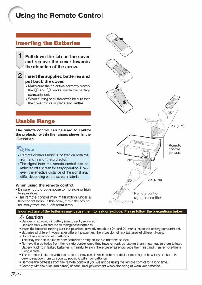
Inserting the Batteries
1 Pull down the tab on the cover and remove the cover towards the direction of the arrow.
2 Insert the supplied batteries and put back the cover. • Make sure the polarities correctly match
the m and n marks inside the battery
compartment.
• When putting back the cover, be sure that
the cover clicks in place and settles.
Usable Range
The remote control can be used to control the projector within the ranges shown in the illustration.
Note
• Remote control sensor is located on both the
front and rear of the projector.
• The signal from the remote control can be
refl ected off a screen for easy operation. How-
ever, the effective distance of the signal may
differ depending on the screen material.
When using the remote control:• Be sure not to drop, expose to moisture or high
temperature.• The remote control may malfunction under a
fl uorescent lamp. In this case, move the projec-tor away from the fl uorescent lamp.
Remote control sensors
30°
30° 23' (7 m)
Remote control
signal transmitter
Remote control
23' (7 m)
30°
30°
Incorrect use of the batteries may cause them to leak or explode. Please follow the precautions below
CautionDanger of explosion if battery is incorrectly replaced.Replace only with alkaline or manganese batteries.Insert the batteries making sure the polarities correctly match the m and n marks inside the battery compartment.Batteries of different types have different properties, therefore do not mix batteries of different types.Do not mix new and old batteries.This may shorten the life of new batteries or may cause old batteries to leak.Remove the batteries from the remote control once they have run out, as leaving them in can cause them to leak.Battery fl uid from leaked batteries is harmful to skin, therefore ensure you wipe them fi rst and then remove them using a cloth.The batteries included with this projector may run down in a short period, depending on how they are kept. Be sure to replace them as soon as possible with new batteries.Remove the batteries from the remote control if you will not be using the remote control for a long time.Comply with the rules (ordinance) of each local government when disposing of worn-out batteries.
•
•••
•
•
••
XVZ15000_E_US_02.indd 12XVZ15000_E_US_02.indd 12 2009/01/14 15:42:222009/01/14 15:42:22
Quick S
tart
-13
Quick Start
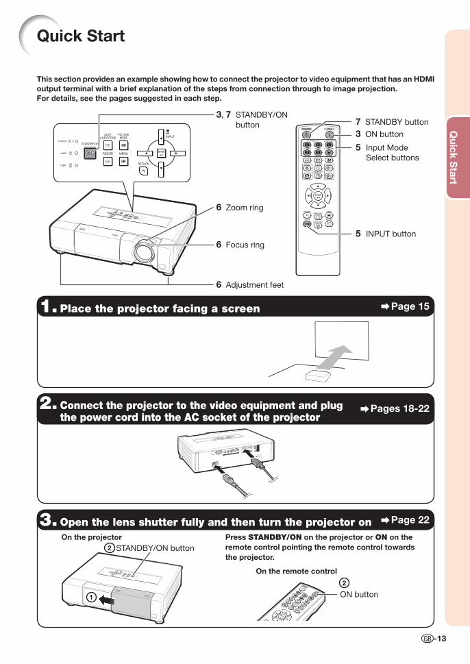
This section provides an example showing how to connect the projector to video equipment that has an HDMI output terminal with a brief explanation of the steps from connection through to image projection.For details, see the pages suggested in each step.
1. Place the projector facing a screen Page 15
2. Connect the projector to the video equipment and plug the power cord into the AC socket of the projector
Pages 18-22
3. Open the lens shutter fully and then turn the projector on Page 22
Press STANDBY/ON on the projector or ON on the remote control pointing the remote control towards the projector.
6 Adjustment feet
6 Focus ring
6 Zoom ring
7 STANDBY button
3 ON button
5 Input Mode
Select buttons
3, 7 STANDBY/ON
button
5 INPUT button
1
2 STANDBY/ON button
On the projector
2
ON button
On the remote control
XV-Z15000_E_US.indb 13XV-Z15000_E_US.indb 13 2008/12/25 14:25:172008/12/25 14:25:17
-14
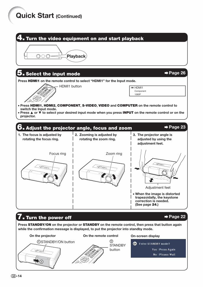
4. Turn the video equipment on and start playback
5. Select the input mode Page 26
Press HDMI1 on the remote control to select “HDMI1” for the Input mode.
• Press HDMI1, HDMI2, COMPONENT, S-VIDEO, VIDEO and COMPUTER on the remote control to switch the Input mode.
• Press P or R to select your desired input mode when you press INPUT on the remote control or on the projector.
6. Adjust the projector angle, focus and zoom Page 23
1. The focus is adjusted by rotating the focus ring.
2. Zooming is adjusted by rotating the zoom ring.
3. The projector angle is adjusted by using the adjustment feet.
Focus ring Zoom ring
Adjustment feet
7. Turn the power off Page 22
Press STANDBY/ON on the projector or STANDBY on the remote control, then press that button again while the confi rmation message is displayed, to put the projector into standby mode.
HDMI1 button
Playback
On-screen display
Quick Start (Continued)
• When the image is distorted trapezoidally, the keystone correction is needed. (See page 24.)
1
STANDBY
button
On the remote control
HDMI1Component
1080P
On the projector
2
1 STANDBY/ON button
XV-Z15000_E_US.indb 14XV-Z15000_E_US.indb 14 2008/12/25 14:25:182008/12/25 14:25:18
Setup
-15
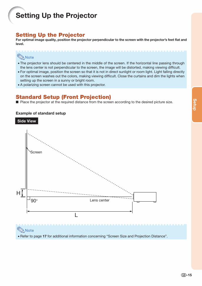
Setting Up the Projector
Setting Up the ProjectorFor optimal image quality, position the projector perpendicular to the screen with the projector’s feet fl at and level.
Note
• The projector lens should be centered in the middle of the screen. If the horizontal line passing through
the lens center is not perpendicular to the screen, the image will be distorted, making viewing diffi cult.
• For optimal image, position the screen so that it is not in direct sunlight or room light. Light falling directly
on the screen washes out the colors, making viewing diffi cult. Close the curtains and dim the lights when
setting up the screen in a sunny or bright room.
• A polarizing screen cannot be used with this projector.
Standard Setup (Front Projection)■ Place the projector at the required distance from the screen according to the desired picture size.
Example of standard setup
Side View
Note
• Refer to page 17 for additional information concerning “Screen Size and Projection Distance”.
H
L
90°
Screen
Lens center
XV-Z15000_E_US.indb 15XV-Z15000_E_US.indb 15 2008/12/25 14:25:182008/12/25 14:25:18
-16
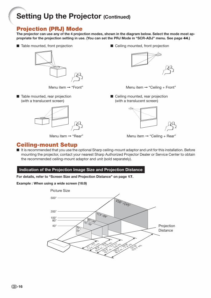
Projection (PRJ) ModeThe projector can use any of the 4 projection modes, shown in the diagram below. Select the mode most ap-propriate for the projection setting in use. (You can set the PRJ Mode in “SCR-ADJ” menu. See page 44.)
■ Table mounted, front projection ■ Ceiling mounted, front projection
Menu item ➞ “Front”
■ Table mounted, rear projection
(with a translucent screen)
Menu item ➞ “Rear”
Menu item ➞ “Ceiling + Front”
■ Ceiling mounted, rear projection
(with a translucent screen)
For details, refer to “Screen Size and Projection Distance” on page 17.
Example : When using a wide screen (16:9)
Indication of the Projection Image Size and Projection Distance
4'1" ~ 4'9"
(1.3 m ~ 1.4 m)
8'3" ~ 9'6"
(2.5 m ~ 2.9 m
)
10'4" ~ 11'11"
(3.1 m ~ 3.6 m
)
20'7" ~ 23'9"
(6.3 m ~ 7.2 m
)
51'6"
(15.7 m)
500"
200"
100"80"
40"
436"×245"
174"×98"87"×49"70"×39"
35"× 20"
Picture Size
Projection
Distance
Ceiling-mount Setup■ It is recommended that you use the optional Sharp ceiling-mount adaptor and unit for this installation. Before
mounting the projector, contact your nearest Sharp Authorized Projector Dealer or Service Center to obtain
the recommended ceiling-mount adaptor and unit (sold separately).
Menu item ➞ “Ceiling + Rear”
Setting Up the Projector (Continued)
XV-Z15000_E_US.indb 16XV-Z15000_E_US.indb 16 2008/12/25 14:25:192008/12/25 14:25:19
Setup
-17
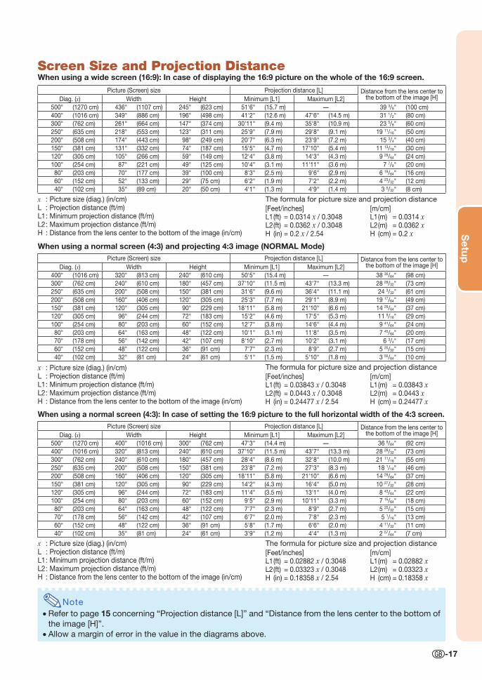
Screen Size and Projection DistanceWhen using a wide screen (16:9): In case of displaying the 16:9 picture on the whole of the 16:9 screen.
x : Picture size (diag.) (in/cm)L : Projection distance (ft/m)L1 : Minimum projection distance (ft/m)L2 : Maximum projection distance (ft/m)H : Distance from the lens center to the bottom of the image (in/cm)
Note
• Refer to page 15 concerning “Projection distance [L]” and “Distance from the lens center to the bottom of
the image [H]”.
• Allow a margin of error in the value in the diagrams above.
The formula for picture size and projection distance
Picture (Screen) size Projection distance [L] Distance from the lens center to the bottom of the image [H]Diag. (x) Width Height Minimum [L1] Maximum [L2]
500" (1270 cm) 436" (1107 cm) 245" (623 cm) 51'6" (15.7 m) — 39 3/8" (100 cm)
400" (1016 cm) 349" (886 cm) 196" (498 cm) 41'2" (12.6 m) 47'6" (14.5 m) 31 1/2" (80 cm)
300" (762 cm) 261" (664 cm) 147" (374 cm) 30'11" (9.4 m) 35'8" (10.9 m) 23 5/8" (60 cm)
250" (635 cm) 218" (553 cm) 123" (311 cm) 25'9" (7.9 m) 29'8" (9.1 m) 19 11/16" (50 cm)
200" (508 cm) 174" (443 cm) 98" (249 cm) 20'7" (6.3 m) 23'9" (7.2 m) 15 3/4" (40 cm)
150" (381 cm) 131" (332 cm) 74" (187 cm) 15'5" (4.7 m) 17'10" (5.4 m) 11 13/16" (30 cm)
120" (305 cm) 105" (266 cm) 59" (149 cm) 12'4" (3.8 m) 14'3" (4.3 m) 9 29/64" (24 cm)
100" (254 cm) 87" (221 cm) 49" (125 cm) 10'4" (3.1 m) 11'11" (3.6 m) 7 7/8" (20 cm)
80" (203 cm) 70" (177 cm) 39" (100 cm) 8'3" (2.5 m) 9'6" (2.9 m) 6 19/64" (16 cm)
60" (152 cm) 52" (133 cm) 29" (75 cm) 6'2" (1.9 m) 7'2" (2.2 m) 4 23/32" (12 cm)
40" (102 cm) 35" (89 cm) 20" (50 cm) 4'1" (1.3 m) 4'9" (1.4 m) 3 5/32" (8 cm)
[Feet/inches]L1 (ft) = 0.0314 x / 0.3048L2 (ft) = 0.0362 x / 0.3048H (in) = 0.2 x / 2.54
[m/cm]L1 (m) = 0.0314 xL2 (m) = 0.0362 xH (cm) = 0.2 x
When using a normal screen (4:3) and projecting 4:3 image (NORMAL Mode)
x : Picture size (diag.) (in/cm)L : Projection distance (ft/m)L1 : Minimum projection distance (ft/m)L2 : Maximum projection distance (ft/m)H : Distance from the lens center to the bottom of the image (in/cm)
The formula for picture size and projection distance
Picture (Screen) size Projection distance [L] Distance from the lens center to the bottom of the image [H]Diag. (x) Width Height Minimum [L1] Maximum [L2]
400" (1016 cm) 320" (813 cm) 240" (610 cm) 50'5" (15.4 m) — 38 35/64" (98 cm)
300" (762 cm) 240" (610 cm) 180" (457 cm) 37'10" (11.5 m) 43'7" (13.3 m) 28 29/32" (73 cm)
250" (635 cm) 200" (508 cm) 150" (381 cm) 31'6" (9.6 m) 36'4" (11.1 m) 24 3/32" (61 cm)
200" (508 cm) 160" (406 cm) 120" (305 cm) 25'3" (7.7 m) 29'1" (8.9 m) 19 17/64" (49 cm)
150" (381 cm) 120" (305 cm) 90" (229 cm) 18'11" (5.8 m) 21'10" (6.6 m) 14 29/64" (37 cm)
120" (305 cm) 96" (244 cm) 72" (183 cm) 15'2" (4.6 m) 17'5" (5.3 m) 11 9/16" (29 cm)
100" (254 cm) 80" (203 cm) 60" (152 cm) 12'7" (3.8 m) 14'6" (4.4 m) 9 41/64" (24 cm)
80" (203 cm) 64" (163 cm) 48" (122 cm) 10'1" (3.1 m) 11'8" (3.5 m) 7 45/64" (20 cm)
70" (178 cm) 56" (142 cm) 42" (107 cm) 8'10" (2.7 m) 10'2" (3.1 m) 6 3/4" (17 cm)
60" (152 cm) 48" (122 cm) 36" (91 cm) 7'7" (2.3 m) 8'9" (2.7 m) 5 25/32" (15 cm)
40" (102 cm) 32" (81 cm) 24" (61 cm) 5'1" (1.5 m) 5'10" (1.8 m) 3 55/64" (10 cm)
[Feet/inches]L1 (ft) = 0.03843 x / 0.3048L2 (ft) = 0.0443 x / 0.3048H (in) = 0.24477 x / 2.54
[m/cm]L1 (m) = 0.03843 xL2 (m) = 0.0443 xH (cm) = 0.24477 x
When using a normal screen (4:3): In case of setting the 16:9 picture to the full horizontal width of the 4:3 screen.
x : Picture size (diag.) (in/cm)L : Projection distance (ft/m)L1 : Minimum projection distance (ft/m)L2 : Maximum projection distance (ft/m)H : Distance from the lens center to the bottom of the image (in/cm)
The formula for picture size and projection distance
Picture (Screen) size Projection distance [L] Distance from the lens center to the bottom of the image [H]Diag. (x) Width Height Minimum [L1] Maximum [L2]
500" (1270 cm) 400" (1016 cm) 300" (762 cm) 47'3" (14.4 m) — 36 9/64" (92 cm)
400" (1016 cm) 320" (813 cm) 240" (610 cm) 37'10" (11.5 m) 43'7" (13.3 m) 28 29/32" (73 cm)
300" (762 cm) 240" (610 cm) 180" (457 cm) 28'4" (8.6 m) 32'8" (10.0 m) 21 11/16" (55 cm)
250" (635 cm) 200" (508 cm) 150" (381 cm) 23'8" (7.2 m) 27'3" (8.3 m) 18 1/16" (46 cm)
200" (508 cm) 160" (406 cm) 120" (305 cm) 18'11" (5.8 m) 21'10" (6.6 m) 14 29/64" (37 cm)
150" (381 cm) 120" (305 cm) 90" (229 cm) 14'2" (4.3 m) 16'4" (5.0 m) 10 27/32" (28 cm)
120" (305 cm) 96" (244 cm) 72" (183 cm) 11'4" (3.5 m) 13'1" (4.0 m) 8 43/64" (22 cm)
100" (254 cm) 80" (203 cm) 60" (152 cm) 9'5" (2.9 m) 10'11" (3.3 m) 7 15/64" (18 cm)
80" (203 cm) 64" (163 cm) 48" (122 cm) 7'7" (2.3 m) 8'9" (2.7 m) 5 25/32" (15 cm)
70" (178 cm) 56" (142 cm) 42" (107 cm) 6'7" (2.0 m) 7'8" (2.3 m) 5 1/16" (13 cm)
60" (152 cm) 48" (122 cm) 36" (91 cm) 5'8" (1.7 m) 6'6" (2.0 m) 4 11/32" (11 cm)
40" (102 cm) 35" (81 cm) 24" (61 cm) 3'9" (1.2 m) 4'4" (1.3 m) 2 57/64" (7 cm)
[Feet/inches]L1 (ft) = 0.02882 x / 0.3048L2 (ft) = 0.03323 x / 0.3048H (in) = 0.18358 x / 2.54
[m/cm]L1 (m) = 0.02882 xL2 (m) = 0.03323 xH (cm) = 0.18358 x
XV-Z15000_E_US.indb 17XV-Z15000_E_US.indb 17 2008/12/25 14:25:192008/12/25 14:25:19
-18
EquipmentTerminal on connected equipment
Cable Terminal on the projector
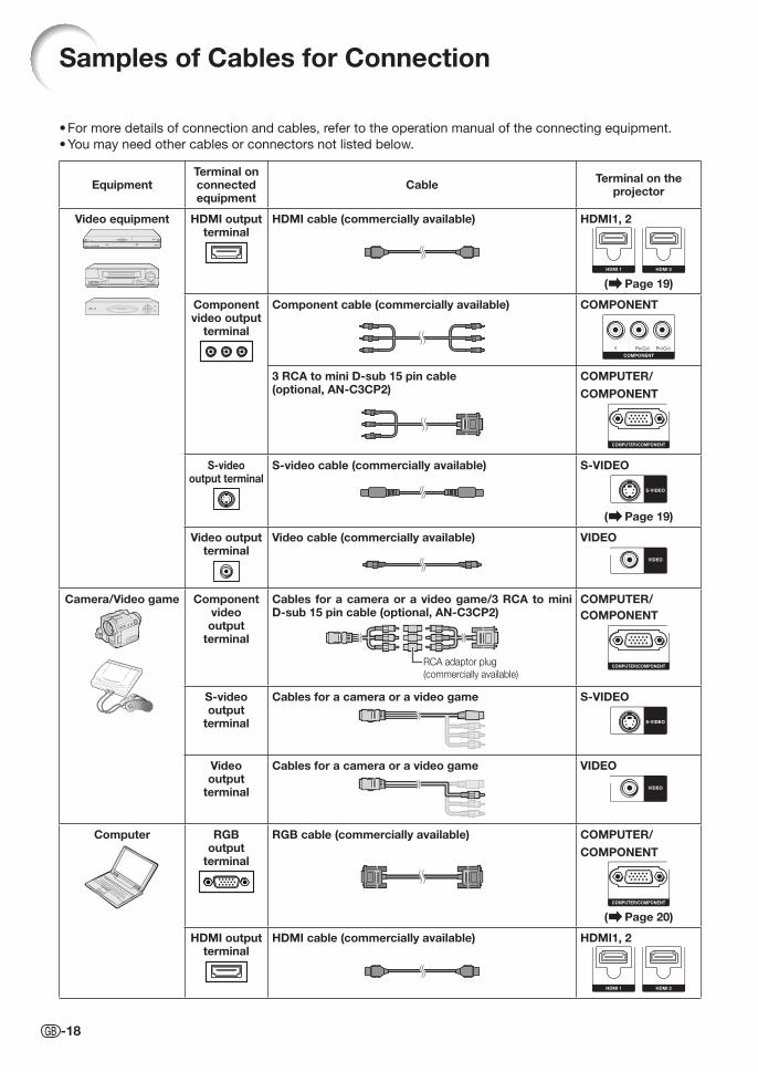
Video equipment HDMI output terminal
HDMI cable (commercially available) HDMI1, 2
( Page 19)
Component video output
terminal
Component cable (commercially available) COMPONENT
3 RCA to mini D-sub 15 pin cable (optional, AN-C3CP2)
COMPUTER/
COMPONENT
S-video output terminal
S-video cable (commercially available) S-VIDEO
( Page 19)
Video output terminal
Video cable (commercially available) VIDEO
Camera/Video game Component video output
terminal
Cables for a camera or a video game/3 RCA to mini D-sub 15 pin cable (optional, AN-C3CP2)
RCA adaptor plug
(commercially available)
COMPUTER/COMPONENT
S-video output
terminal
Cables for a camera or a video game S-VIDEO
Video output
terminal
Cables for a camera or a video game VIDEO
Computer RGBoutput
terminal
RGB cable (commercially available) COMPUTER/
COMPONENT
( Page 20)
HDMI output terminal
HDMI cable (commercially available) HDMI1, 2
Samples of Cables for Connection
For more details of connection and cables, refer to the operation manual of the connecting equipment.
You may need other cables or connectors not listed below.
•
•
XV-Z15000_E_US.indb 18XV-Z15000_E_US.indb 18 2008/12/25 14:25:202008/12/25 14:25:20
Co
nnections
-19
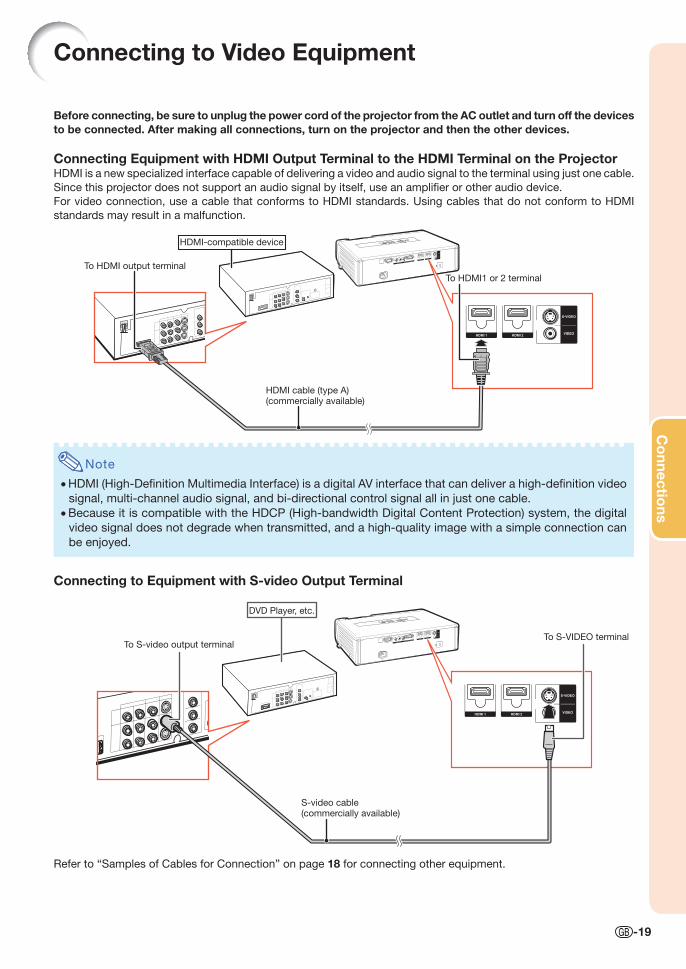
Before connecting, be sure to unplug the power cord of the projector from the AC outlet and turn off the devices to be connected. After making all connections, turn on the projector and then the other devices.
Connecting Equipment with HDMI Output Terminal to the HDMI Terminal on the ProjectorHDMI is a new specialized interface capable of delivering a video and audio signal to the terminal using just one cable.
Since this projector does not support an audio signal by itself, use an amplifi er or other audio device.
For video connection, use a cable that conforms to HDMI standards. Using cables that do not conform to HDMI
standards may result in a malfunction.
Note
• HDMI (High-Defi nition Multimedia Interface) is a digital AV interface that can deliver a high-defi nition video
signal, multi-channel audio signal, and bi-directional control signal all in just one cable.
• Because it is compatible with the HDCP (High-bandwidth Digital Content Protection) system, the digital
video signal does not degrade when transmitted, and a high-quality image with a simple connection can
be enjoyed.
Connecting to Video Equipment
DVD Player, etc.
To S-video output terminal
S-video cable(commercially available)
To S-VIDEO terminal
HDMI-compatible device
To HDMI output terminal
HDMI cable (type A)(commercially available)
To HDMI1 or 2 terminal
Connecting to Equipment with S-video Output Terminal
Refer to “Samples of Cables for Connection” on page 18 for connecting other equipment.
XV-Z15000_E_US.indb 19XV-Z15000_E_US.indb 19 2008/12/25 14:25:222008/12/25 14:25:22
-20
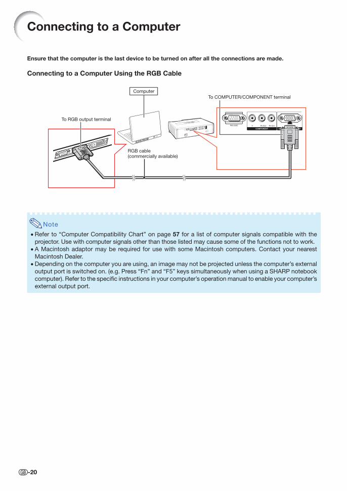
Ensure that the computer is the last device to be turned on after all the connections are made.
Connecting to a Computer Using the RGB Cable
Connecting to a Computer
Note
• Refer to “Computer Compatibility Chart” on page 57 for a list of computer signals compatible with the
projector. Use with computer signals other than those listed may cause some of the functions not to work.
• A Macintosh adaptor may be required for use with some Macintosh computers. Contact your nearest
Macintosh Dealer.
• Depending on the computer you are using, an image may not be projected unless the computer’s external
output port is switched on. (e.g. Press “Fn” and “F5” keys simultaneously when using a SHARP notebook
computer). Refer to the specifi c instructions in your computer’s operation manual to enable your computer’s
external output port.
Computer
To RGB output terminal
RGB cable (commercially available)
To COMPUTER/COMPONENT terminal
XV-Z15000_E_US.indb 20XV-Z15000_E_US.indb 20 2008/12/25 14:25:222008/12/25 14:25:22
Co
nnections
-21
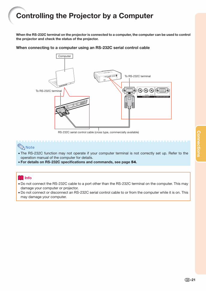
Controlling the Projector by a Computer
When the RS-232C terminal on the projector is connected to a computer, the computer can be used to control the projector and check the status of the projector.
When connecting to a computer using an RS-232C serial control cable
Note
• The RS-232C function may not operate if your computer terminal is not correctly set up. Refer to the
operation manual of the computer for details.
• For details on RS-232C specifi cations and commands, see page 54.
Info
• Do not connect the RS-232C cable to a port other than the RS-232C terminal on the computer. This may
damage your computer or projector.
• Do not connect or disconnect an RS-232C serial control cable to or from the computer while it is on. This
may damage your computer.
Computer
To RS-232C terminal
RS-232C serial control cable (cross type, commercially available)
To RS-232C terminal
XV-Z15000_E_US.indb 21XV-Z15000_E_US.indb 21 2008/12/25 14:25:222008/12/25 14:25:22
-22
Turning the Projector On/Off
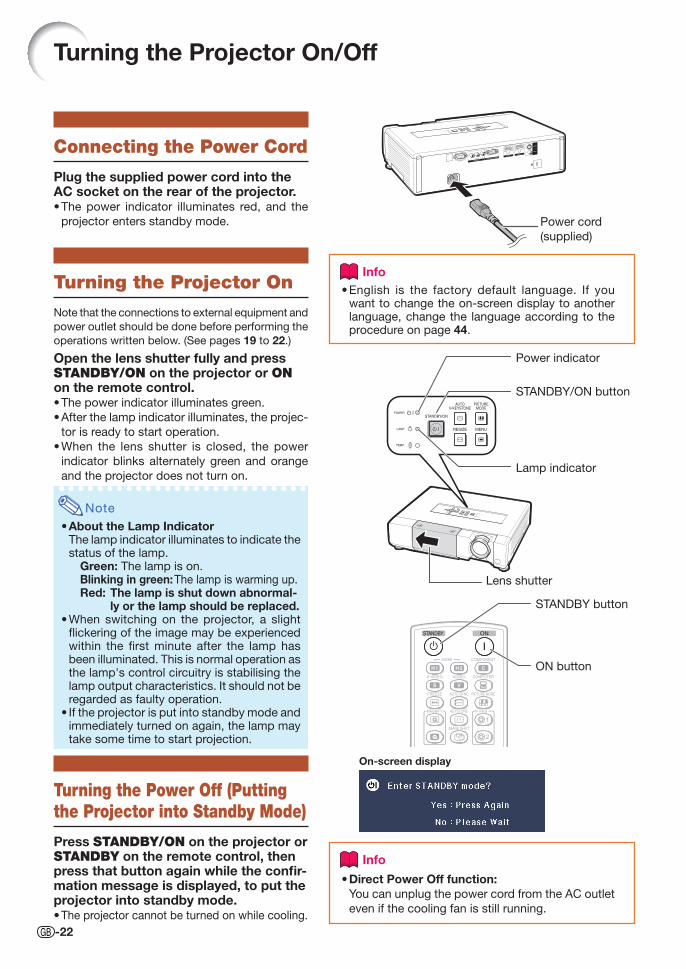
Connecting the Power Cord
Plug the supplied power cord into the AC socket on the rear of the projector.
The power indicator illuminates red, and the
projector enters standby mode.
Turning the Projector On
Note that the connections to external equipment and
power outlet should be done before performing the
operations written below. (See pages 19 to 22.)
Open the lens shutter fully and press STANDBY/ON on the projector or ON on the remote control.
The power indicator illuminates green.
After the lamp indicator illuminates, the projec-
tor is ready to start operation.
When the lens shutter is closed, the power
indicator blinks alternately green and orange
and the projector does not turn on.
Note
About the Lamp IndicatorThe lamp indicator illuminates to indicate the status of the lamp.
Green: The lamp is on.Blinking in green: The lamp is warming up.Red: The lamp is shut down abnormal-
ly or the lamp should be replaced.When switching on the projector, a slight fl ickering of the image may be experienced within the fi rst minute after the lamp has been illuminated. This is normal operation as the lamp's control circuitry is stabilising the lamp output characteristics. It should not be regarded as faulty operation.If the projector is put into standby mode and immediately turned on again, the lamp may take some time to start projection.
Turning the Power Off (Putting the Projector into Standby Mode)
Press STANDBY/ON on the projector or STANDBY on the remote control, then press that button again while the confi r-mation message is displayed, to put the projector into standby mode.
The projector cannot be turned on while cooling.
•
•
•
•
•
•
•
•
On-screen display
STANDBY button
ON button
InfoEnglish is the factory default language. If you want to change the on-screen display to another language, change the language according to the procedure on page 44.
•
Power cord
(supplied)
STANDBY/ON button
Lamp indicator
Power indicator
Lens shutter
Info
Direct Power Off function:You can unplug the power cord from the AC outlet
even if the cooling fan is still running.
•
XV-Z15000_E_US.indb 22XV-Z15000_E_US.indb 22 2008/12/25 14:25:232008/12/25 14:25:23
Basic O
peratio
n
-23
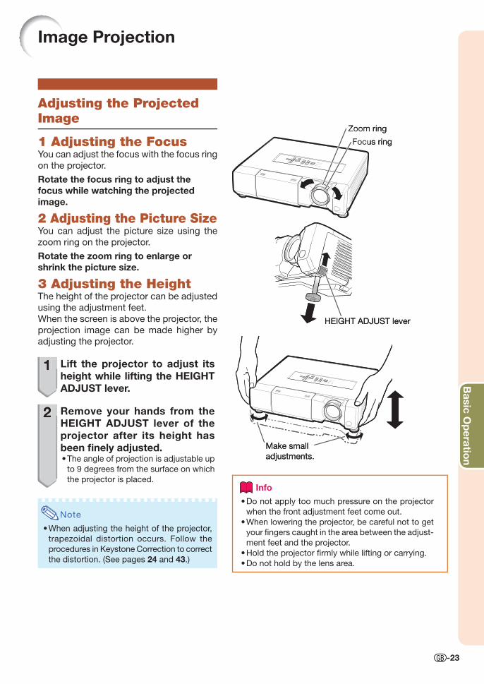
Image Projection
Adjusting the Projected Image
1 Adjusting the FocusYou can adjust the focus with the focus ring
on the projector.
Rotate the focus ring to adjust the focus while watching the projected image.
2 Adjusting the Picture SizeYou can adjust the picture size using the
zoom ring on the projector.
Rotate the zoom ring to enlarge or shrink the picture size.
3 Adjusting the HeightThe height of the projector can be adjusted
using the adjustment feet.
When the screen is above the projector, the
projection image can be made higher by
adjusting the projector.
1 Lift the projector to adjust its height while lifting the HEIGHT ADJUST lever.
2 Remove your hands from the HEIGHT ADJUST lever of the projector after its height has been fi nely adjusted.
The angle of projection is adjustable up
to 9 degrees from the surface on which
the projector is placed.
Note
When adjusting the height of the projector,
trapezoidal distortion occurs. Follow the
procedures in Keystone Correction to correct
the distortion. (See pages 24 and 43.)
•
•
Focus ring
Zoom ring
Focus ring
Zoom ring
Make small
adjustments.
HEIGHT ADJUST lever
Make small
adjustments.
HEIGHT ADJUST lever
1
2
Info
Do not apply too much pressure on the projector
when the front adjustment feet come out.
When lowering the projector, be careful not to get
your fi ngers caught in the area between the adjust-
ment feet and the projector.
Hold the projector fi rmly while lifting or carrying.
Do not hold by the lens area.
•
•
•
•
XV-Z15000_E_US.indb 23XV-Z15000_E_US.indb 23 2008/12/25 14:25:252008/12/25 14:25:25
-24
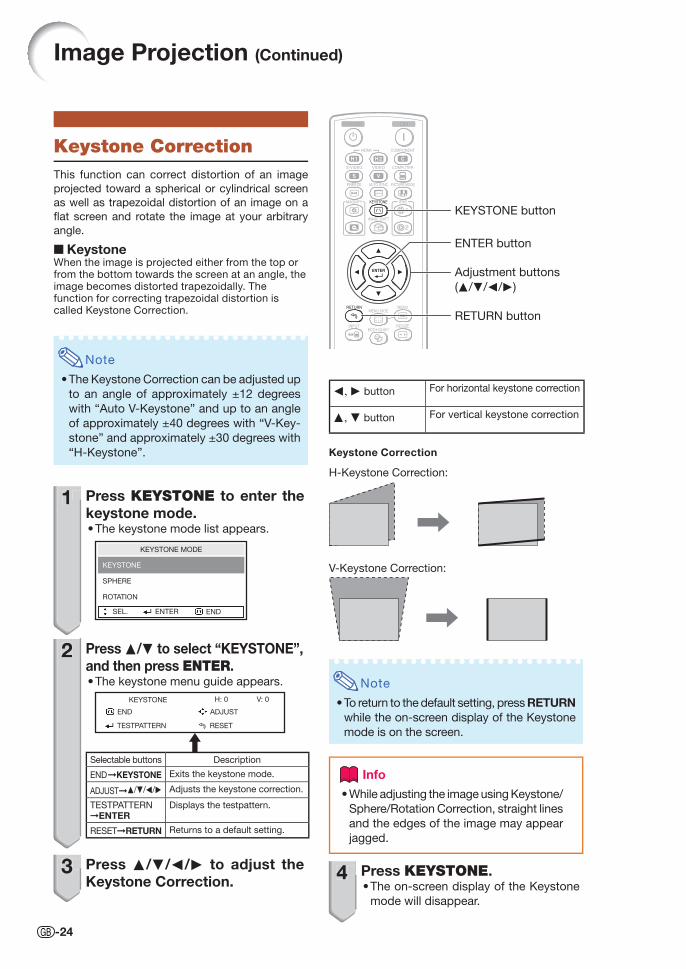
Keystone CorrectionThis function can correct distortion of an image
projected toward a spherical or cylindrical screen
as well as trapezoidal distortion of an image on a
fl at screen and rotate the image at your arbitrary
angle.
■ KeystoneWhen the image is projected either from the top or from the bottom towards the screen at an angle, the image becomes distorted trapezoidally. The function for correcting trapezoidal distortion is called Keystone Correction.
Note
The Keystone Correction can be adjusted up
to an angle of approximately ±12 degrees
with “Auto V-Keystone” and up to an angle
of approximately ±40 degrees with “V-Key-
stone” and approximately ±30 degrees with
“H-Keystone”.
1 Press KEYSTONE to enter the keystone mode.
The keystone mode list appears.
SEL. ENTER END
SPHERE
ROTATION
KEYSTONE MODE
KEYSTONE
2 Press P/R to select “KEYSTONE”, and then press ENTER.
The keystone menu guide appears.
ADJUST
RESETTESTPATTERN
END
KEYSTONE H: 0 V: 0
Selectable buttons Description
END➞KEYSTONE Exits the keystone mode.
ADJUST➞P/R/O/Q Adjusts the keystone correction.
TESTPATTERN➞ENTER
Displays the testpattern.
RESET➞RETURN Returns to a default setting.
3 Press P/R/O/Q to adjust the Keystone Correction.
•
•
•
1
2
3
KEYSTONE button
Adjustment buttons
(P/R/O/Q)
RETURN button
Image Projection (Continued)
Keystone Correction
H-Keystone Correction:
V-Keystone Correction:
O, Q button For horizontal keystone correction
P, R button For vertical keystone correction
Note
To return to the default setting, press RETURN
while the on-screen display of the Keystone
mode is on the screen.
Info
While adjusting the image using Keystone/
Sphere/Rotation Correction, straight lines
and the edges of the image may appear
jagged.
•
4 Press KEYSTONE.The on-screen display of the Keystone
mode will disappear.
•
•4
ENTER button
XV-Z15000_E_US.indb 24XV-Z15000_E_US.indb 24 2008/12/25 14:25:282008/12/25 14:25:28
Basic O
peratio
n
-25
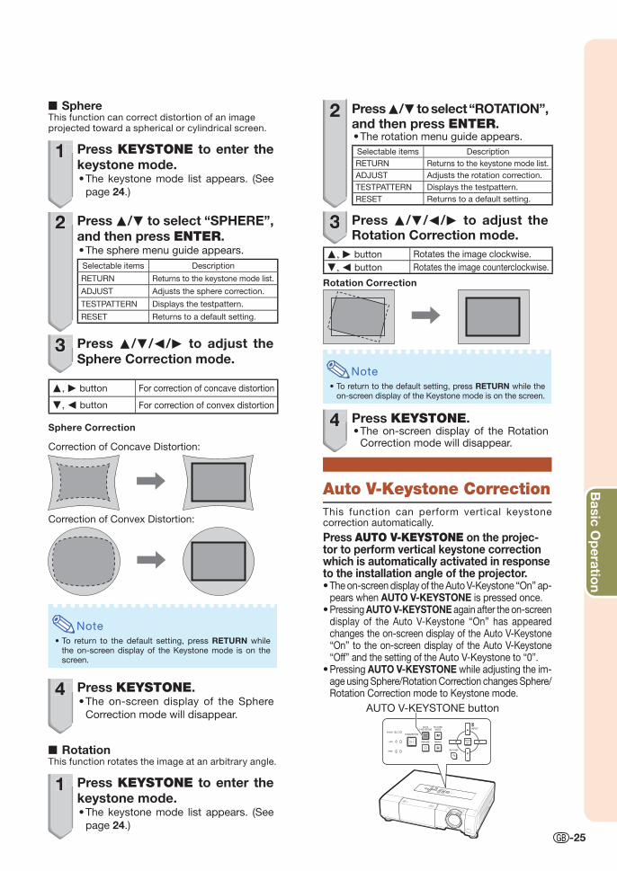
■ SphereThis function can correct distortion of an image projected toward a spherical or cylindrical screen.
1 Press KEYSTONE to enter the keystone mode.
The keystone mode list appears. (See
page 24.)
2 Press P/R to select “SPHERE”, and then press ENTER.
The sphere menu guide appears.
Selectable items Description
RETURN Returns to the keystone mode list.
ADJUST Adjusts the sphere correction.
TESTPATTERN Displays the testpattern.
RESET Returns to a default setting.
3 Press P/R/O/Q to adjust the Sphere Correction mode.
P, Q button For correction of concave distortion
R, O button For correction of convex distortion
Sphere Correction
Correction of Concave Distortion:
Correction of Convex Distortion:
Note
To return to the default setting, press RETURN while the on-screen display of the Keystone mode is on the screen.
4 Press KEYSTONE.The on-screen display of the Sphere
Correction mode will disappear.
■ RotationThis function rotates the image at an arbitrary angle.
1 Press KEYSTONE to enter the keystone mode.
The keystone mode list appears. (See
page 24.)
•
•
•
•
•
1
2
3
4
1
2 Press P/R to select “ROTATION”, and then press ENTER.
The rotation menu guide appears.
Selectable items Description
RETURN Returns to the keystone mode list.
ADJUST Adjusts the rotation correction.
TESTPATTERN Displays the testpattern.
RESET Returns to a default setting.
3 Press P/R/O/Q to adjust the Rotation Correction mode.
P, Q button Rotates the image clockwise.
R, O button Rotates the image counterclockwise.
Rotation Correction
Note
To return to the default setting, press RETURN while the on-screen display of the Keystone mode is on the screen.
4 Press KEYSTONE.The on-screen display of the Rotation Correction mode will disappear.
Auto V-Keystone CorrectionThis function can perform vertical keystone correction automatically.
Press AUTO V-KEYSTONE on the projec-tor to perform vertical keystone correction which is automatically activated in response to the installation angle of the projector.
The on-screen display of the Auto V-Keystone “On” ap-pears when AUTO V-KEYSTONE is pressed once.Pressing AUTO V-KEYSTONE again after the on-screen display of the Auto V-Keystone “On” has appeared changes the on-screen display of the Auto V-Keystone “On” to the on-screen display of the Auto V-Keystone “Off” and the setting of the Auto V-Keystone to “0”.Pressing AUTO V-KEYSTONE while adjusting the im-age using Sphere/Rotation Correction changes Sphere/Rotation Correction mode to Keystone mode.
AUTO V-KEYSTONE button
•
•
•
•
•
•
2
3
4
XV-Z15000_E_US.indb 25XV-Z15000_E_US.indb 25 2008/12/25 14:25:292008/12/25 14:25:29
-26
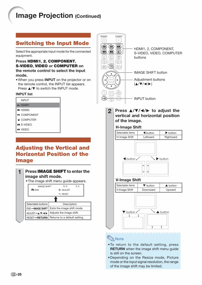
Switching the Input ModeSelect the appropriate input mode for the connected
equipment.
Press HDMI1, 2, COMPONENT, S-VIDEO, VIDEO or COMPUTER on the remote control to select the input mode.
When you press INPUT on the projector or on
the remote control, the INPUT list appears.
Press P/R to switch the INPUT mode.
INPUT
HDMI1
HDMI2
COMPONENT
COMPUTER
S-VIDEO
VIDEO
INPUT list
Adjusting the Vertical and Horizontal Position of the Image
1 Press IMAGE SHIFT to enter the image shift mode.
The image shift menu guide appears.
ADJUST
RESET
END
IMAGE SHIFT V: 0H: 0
Selectable buttons Description
END➞IMAGE SHIFT Exits the image shift mode.
ADJUST➞P/R/O/Q Adjusts the image shift.
RESET➞RETURN Returns to a default setting.
•
•
1
2 Press P/R/O/Q to adjust the vertical and horizontal position of the image.H-Image ShiftSelectable items \ button | button
H-Image Shift Leftward Rightward
| button\ button
V-Image ShiftSelectable items " button ' button
V-Image Shift Downward Upward
' button" button
Note
To return to the default setting, press
RETURN when the image shift menu guide
is still on the screen.
Depending on the Resize mode, Picture
mode or the input signal resolution, the range
of the image shift may be limited.
•
•
2
Image Projection (Continued)
INPUT button
HDMI1, 2, COMPONENT,
S-VIDEO, VIDEO, COMPUTER
buttons
IMAGE SHIFT button
Adjustment buttons
(P/R/O/Q)
XVZ15000_E_US_05.indd 26XVZ15000_E_US_05.indd 26 2009/01/16 17:37:352009/01/16 17:37:35
Basic O
peratio
n
-27
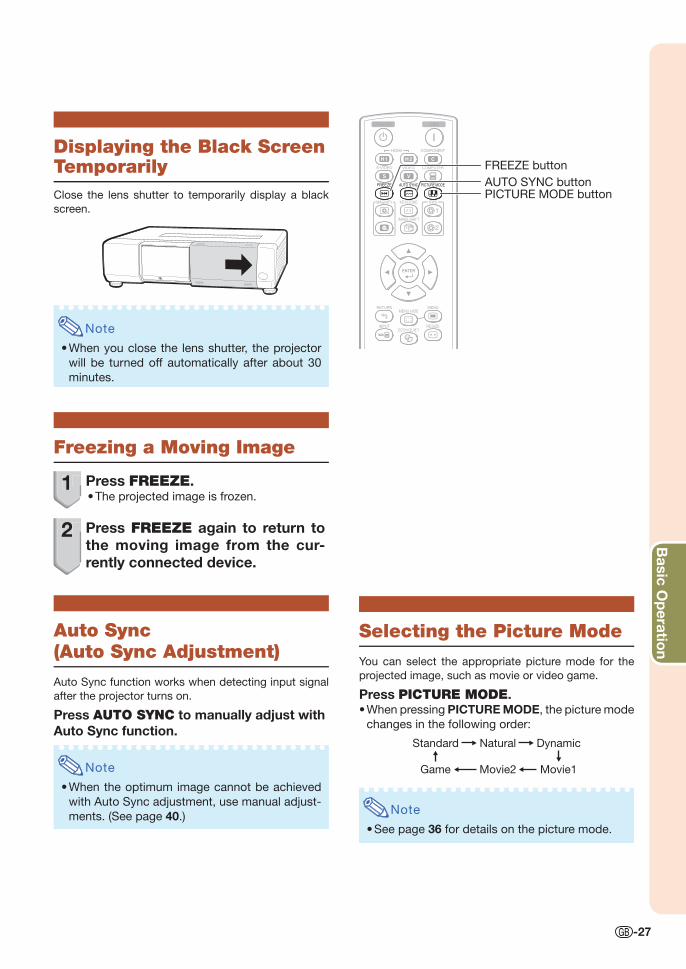
Freezing a Moving Image
1 Press FREEZE.The projected image is frozen.
2 Press FREEZE again to return to the moving image from the cur-rently connected device.
Auto Sync(Auto Sync Adjustment)
Auto Sync function works when detecting input signal
after the projector turns on.
Press AUTO SYNC to manually adjust with Auto Sync function.
Note
When the optimum image cannot be achieved
with Auto Sync adjustment, use manual adjust-
ments. (See page 40.)
•
•
1
2
Selecting the Picture Mode
You can select the appropriate picture mode for the
projected image, such as movie or video game.
Press PICTURE MODE.When pressing PICTURE MODE, the picture mode
changes in the following order:
NaturalStandard Dynamic
Movie2Game Movie1
Note
See page 36 for details on the picture mode.
•
•
FREEZE button
AUTO SYNC buttonPICTURE MODE button
Displaying the Black Screen TemporarilyClose the lens shutter to temporarily display a black
screen.
Note
When you close the lens shutter, the projector
will be turned off automatically after about 30
minutes.
•
XV-Z15000_E_US.indb 27XV-Z15000_E_US.indb 27 2008/12/25 14:25:312008/12/25 14:25:31
-28
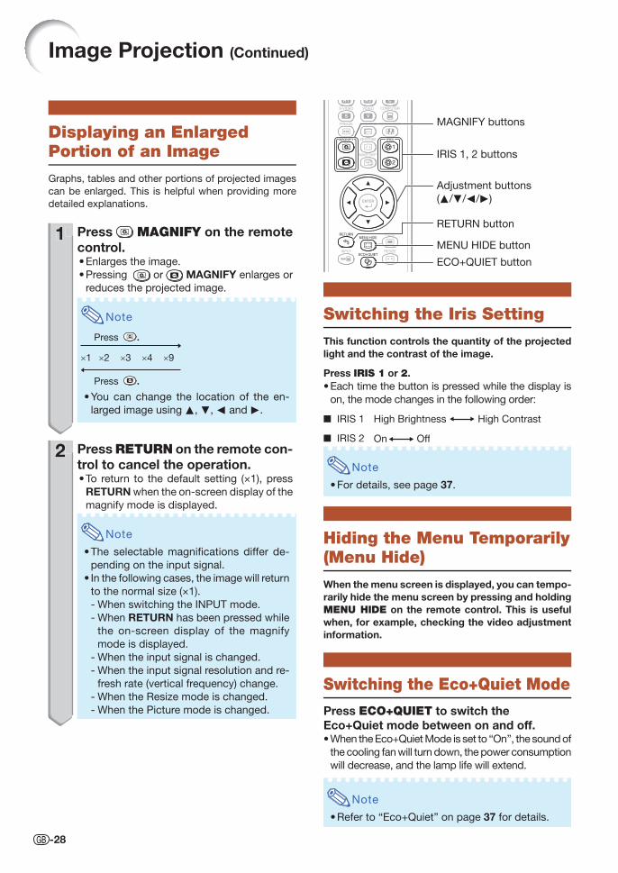
Displaying an Enlarged Portion of an Image
Graphs, tables and other portions of projected images
can be enlarged. This is helpful when providing more
detailed explanations.
1 Press MAGNIFY on the remote control.
Enlarges the image.
Pressing or MAGNIFY enlarges or
reduces the projected image.
Note
×1 ×2 ×3 ×4 ×9
Press .
Press .
You can change the location of the en-
larged image using P, R, O and Q.
2 Press RETURN on the remote con-trol to cancel the operation.
To return to the default setting (×1), press
RETURN when the on-screen display of the
magnify mode is displayed.
Note
The selectable magnifi cations differ de-
pending on the input signal.
In the following cases, the image will return
to the normal size (×1).
When switching the INPUT mode.
When RETURN has been pressed while
the on-screen display of the magnify
mode is displayed.
When the input signal is changed.
When the input signal resolution and re-
fresh rate (vertical frequency) change.
When the Resize mode is changed.
When the Picture mode is changed.
•
•
•
•
•
•
-
-
-
-
-
-
1
2
Switching the Iris Setting
This function controls the quantity of the projected light and the contrast of the image.
Press IRIS 1 or 2.Each time the button is pressed while the display is
on, the mode changes in the following order:
IRIS 1 High Brightness High Contrast
IRIS 2 OffOn
Note
For details, see page 37.
Hiding the Menu Temporarily (Menu Hide)
When the menu screen is displayed, you can tempo-rarily hide the menu screen by pressing and holding MENU HIDE on the remote control. This is useful when, for example, checking the video adjustment information.
Switching the Eco+Quiet Mode
Press ECO+QUIET to switch the Eco+Quiet mode between on and off.
When the Eco+Quiet Mode is set to “On”, the sound of
the cooling fan will turn down, the power consumption
will decrease, and the lamp life will extend.
Note
Refer to “Eco+Quiet” on page 37 for details.
•
■
■
•
•
•
Image Projection (Continued)
IRIS 1, 2 buttons
MENU HIDE button
MAGNIFY buttons
Adjustment buttons
(P/R/O/Q)
RETURN button
ECO+QUIET button
XV-Z15000_E_US.indb 28XV-Z15000_E_US.indb 28 2008/12/25 14:25:312008/12/25 14:25:31
Basic O
peratio
n
-29
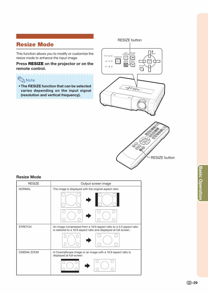
Resize Mode
This function allows you to modify or customize the
resize mode to enhance the input image.
Press RESIZE on the projector or on the remote control.
Note
The RESIZE function that can be selected varies depending on the input signal(resolution and vertical frequency).
•
RESIZE button
RESIZE button
Resize Mode
RESIZE Output screen image
NORMAL The image is displayed with the original aspect ratio.
STRETCH An image compressed from a 16:9 aspect ratio to a 4:3 aspect ratio is restored to a 16:9 aspect ratio and displayed at full-screen.
CINEMA ZOOM A CinemaScope image or an image with a 16:9 aspect ratio is displayed at full-screen
XV-Z15000_E_US.indb 29XV-Z15000_E_US.indb 29 2008/12/25 14:25:322008/12/25 14:25:32
-30
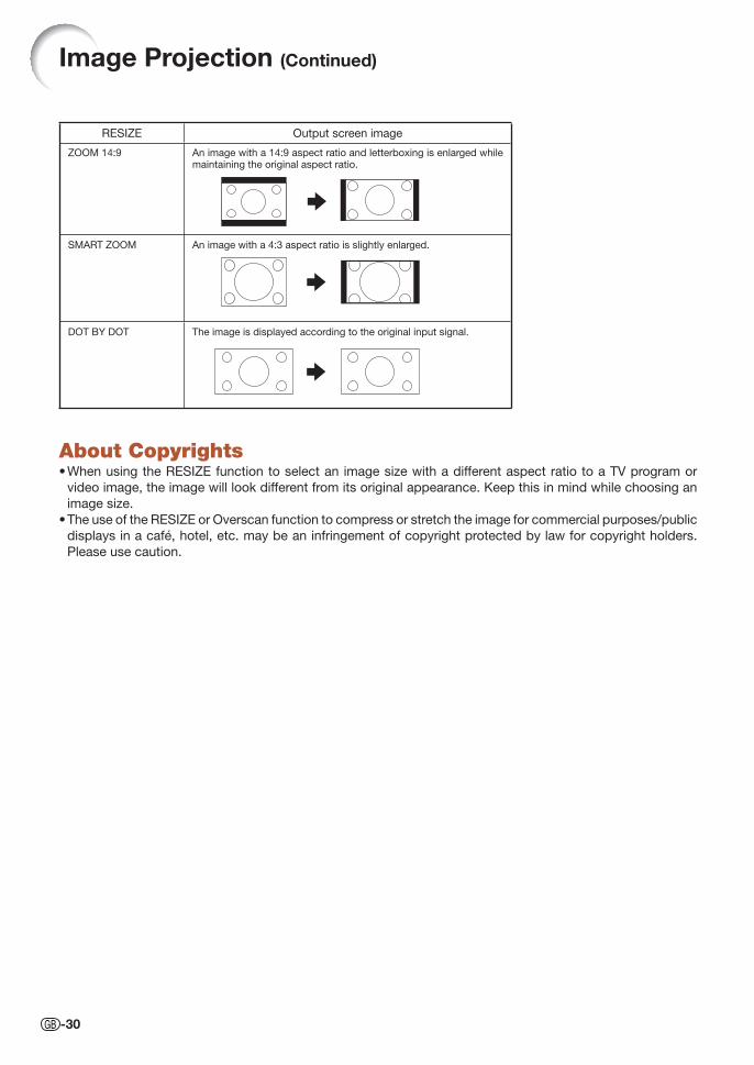
About CopyrightsWhen using the RESIZE function to select an image size with a different aspect ratio to a TV program or
video image, the image will look different from its original appearance. Keep this in mind while choosing an
image size.
The use of the RESIZE or Overscan function to compress or stretch the image for commercial purposes/public
displays in a café, hotel, etc. may be an infringement of copyright protected by law for copyright holders.
Please use caution.
•
•
RESIZE Output screen image
ZOOM 14:9 An image with a 14:9 aspect ratio and letterboxing is enlarged while maintaining the original aspect ratio.
SMART ZOOM An image with a 4:3 aspect ratio is slightly enlarged.
DOT BY DOT The image is displayed according to the original input signal.
Image Projection (Continued)
XV-Z15000_E_US.indb 30XV-Z15000_E_US.indb 30 2008/12/25 14:25:332008/12/25 14:25:33
Useful Features
-31
Menu Bar Items
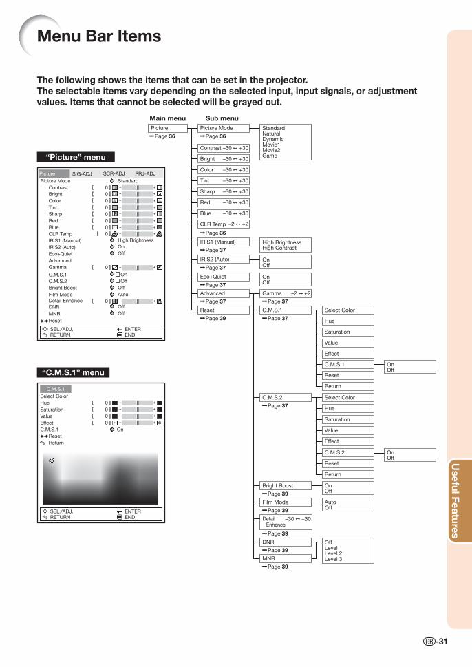
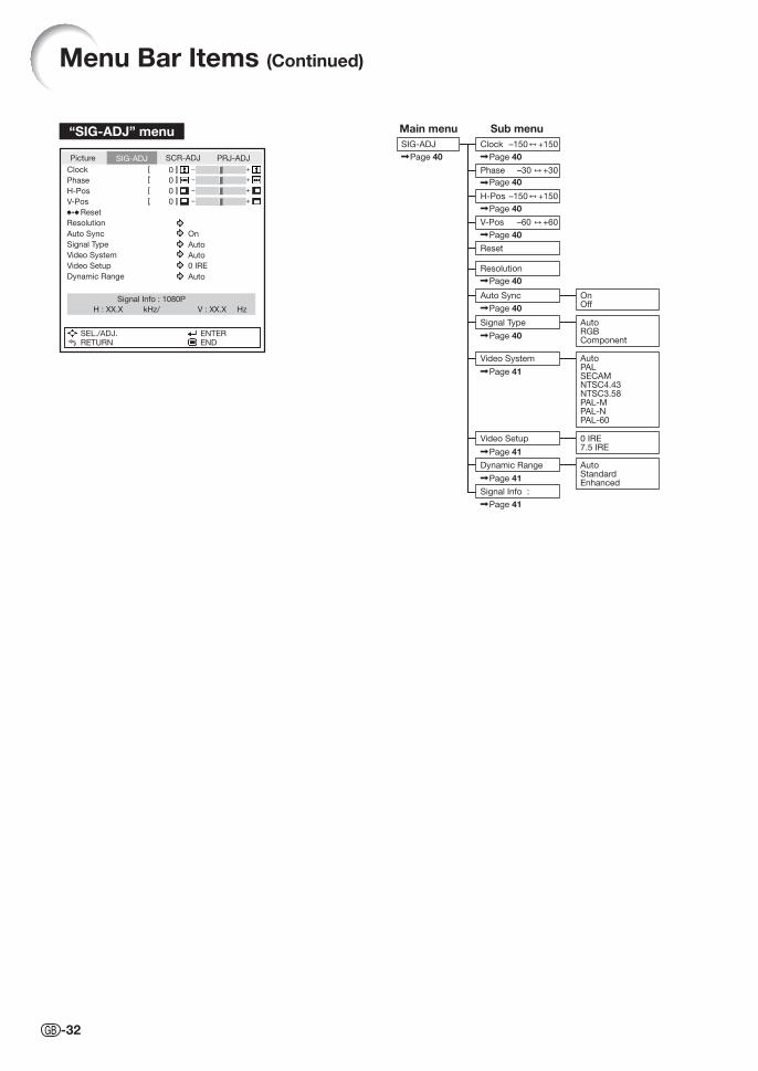
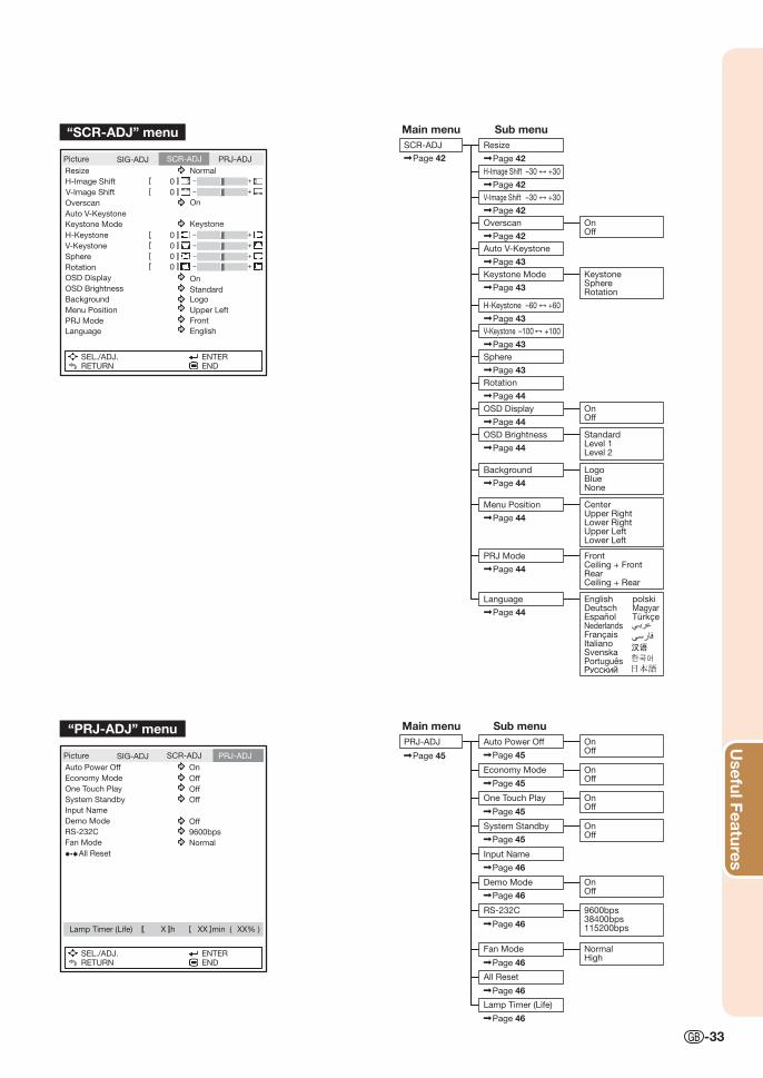
The following shows the items that can be set in the projector.The selectable items vary depending on the selected input, input signals, or adjustment values. Items that cannot be selected will be grayed out.
StandardNaturalDynamicMovie1Movie2Game
+30–30
+30–30
+30–30
+2–2
+30–30
Main menu Sub menu
Contrast
Picture Mode
Bright
Sharp
Red
Blue
CLR Temp
+30–30
+30–30Color
Tint
IRIS2 (Auto)
Eco+Quiet
Picture
Page 36
OnOff
OnOff
Advanced
Select Color
Hue
Effect
C.M.S.1
Reset
Return
Page 36
Page 36
Page 37
IRIS1 (Manual) High BrightnessHigh ContrastPage 37
Page 37
Page 37
Page 37
Gamma
Page 37
Page 39
Page 37
Page 39
+2–2
C.M.S.1
C.M.S.2
Saturation
Value
Reset
On
Off
Select Color
Hue
Effect
C.M.S.2
Reset
Return
Bright Boost
Saturation
Value
OnOff
OnOff
Page 39
Film Mode AutoOff
Page 39
DNR
Page 39
MNR
OffLevel 1Level 2Level 3
OnOff
+30–30
Page 39
Detail Enhance
+30–30
“Picture” menu
“C.M.S.1” menu
Picture
Picture Mode Standard
High Brightness
On
Off
Off
Auto
On
Off
Contrast
Bright
Color
Tint
Sharp
Red
Blue
CLR Temp
IRIS1 (Manual)
IRIS2 (Auto)
Eco+Quiet
Advanced
Gamma
C.M.S.1
C.M.S.2
Bright Boost
Film Mode
Detail Enhance
Reset
SEL./ADJ.RETURN
ENTEREND
SIG-ADJ SCR-ADJ PRJ-ADJ
0
0
0
0
0
0
0
0
0
0
DNR
MNR
Off
Off
C.M.S.1
Select Color
Hue
Saturation
Value
Effect
C.M.S.1 On
Reset
Return
SEL./ADJ.RETURN
ENTEREND
0
0
0
0
XV-Z15000_E_US.indb 31XV-Z15000_E_US.indb 31 2008/12/25 14:25:332008/12/25 14:25:33
-32
Menu Bar Items (Continued)
“SIG-ADJ” menu Main menu Sub menu+150–150
+150–150
+30–30
+60–60
SIG-ADJ Clock
Phase
H-Pos
V-Pos
Reset
Resolution
Auto Sync OnOff
Video Setup
Signal Info :
0 IRE7.5 IRE
Dynamic Range AutoStandardEnhanced
Signal Type AutoRGBComponent
Page 40
Page 40
Page 40
Page 40
Page 40
Page 40
Page 40
Page 40
Video System AutoPALSECAMNTSC4.43NTSC3.58PAL-MPAL-NPAL-60
Page 41
Page 41
Page 41
Page 41
Picture
Clock
Phase
H-Pos
V-Pos
Reset
Resolution
Auto Sync On
Auto
Auto
0 IRE
Auto
Signal Type
Signal Info : 1080P
H : XX.X kHz/ V : XX.X Hz
Video System
Video Setup
Dynamic Range
SEL./ADJ.RETURN
ENTEREND
SIG-ADJ SCR-ADJ PRJ-ADJ
0
0
0
0
XV-Z15000_E_US.indb 32XV-Z15000_E_US.indb 32 2008/12/25 14:25:332008/12/25 14:25:33
Useful Features
-33
“PRJ-ADJ” menu
Page 45 Page 45
Page 45
Page 45
Page 45
Page 46
Page 46
Page 46
Page 46
Page 46
PRJ-ADJ Auto Power Off
Economy Mode
One Touch Play
System Standby
Input Name
Demo Mode
RS-232C
Fan Mode
Page 46
All Reset
Lamp Timer (Life)
OnOff
OnOff
OnOff
OnOff
OnOff
NormalHigh
9600bps38400bps115200bps
Main menu Sub menu
Main menu Sub menuSCR-ADJ
H-Image Shift +30–30
Page 42
Page 42
Page 42
Page 42
V-Image Shift
Overscan OnOff
Resize
Page 42
OSD Display OnOff
Page 44OSD Brightness Standard
Level 1Level 2
Page 44
Background LogoBlueNone
Page 44
Menu Position CenterUpper RightLower RightUpper LeftLower Left
Page 44
PRJ Mode FrontCeiling + FrontRearCeiling + Rear
Page 44
Language EnglishDeutschEspañolNederlandsFrançaisItalianoSvenskaPortuguês
polskiMagyarTürkçe
Page 44
H-Keystone
Page 43
+60–60
V-Keystone
Page 43Sphere
Page 43Rotation
Page 44
+100–100
Auto V-Keystone
Page 43
+30–30
Keystone Mode KeystoneSphereRotation
Page 43
“SCR-ADJ” menu
Picture
Resize Normal
On
On
Standard
Logo
Upper Left
Front
English
Keystone
H-Image Shift
V-Image Shift
Overscan
Auto V-Keystone
Keystone Mode
H-Keystone
V-Keystone
Sphere
Rotation
OSD Display
OSD Brightness
Background
Menu Position
PRJ Mode
Language
SEL./ADJ.RETURN
ENTEREND
SIG-ADJ SCR-ADJ PRJ-ADJ
0
0
0
0
0
0
Picture
Auto Power Off On
Off
Off
Off
Off
9600bps
Normal
Economy Mode
One Touch Play
System Standby
Input Name
Demo Mode
RS-232C
Fan Mode
Lamp Timer (Life) min ( )
All Reset
SEL./ADJ.RETURN
ENTEREND
SIG-ADJ SCR-ADJ PRJ-ADJ
hX XX XX%
XV-Z15000_E_US.indb 33XV-Z15000_E_US.indb 33 2008/12/25 14:25:342008/12/25 14:25:34
-34
Picture
Picture Mode Standard
High Brightness
On
Off
Contrast
Bright
Color
Tint
Sharp
Red
Blue
CLR Temp
IRIS1 (Manual)
IRIS2 (Auto)
Eco+Quiet
Advanced
Reset
SEL./ADJ.RETURN
ENTEREND
SIG-ADJ SCR-ADJ PRJ-ADJ
0
0
0
0
0
0
0
0
Using the Menu Screen
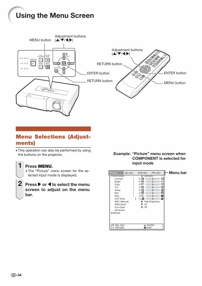
Menu Selections (Adjust-ments)• This operation can also be performed by using
the buttons on the projector.
1 Press MENU.• The “Picture” menu screen for the se-
lected input mode is displayed.
2 Press | or \ to select the menu screen to adjust on the menu bar.
Example: “Picture” menu screen when COMPONENT is selected for input mode
RETURN button
Adjustment buttons('/"/\/|)
ENTER button
MENU button
Adjustment buttons('/"/\/|)
Menu bar
ENTER button
RETURN button
MENU button
XV-Z15000_E_US.indb 34XV-Z15000_E_US.indb 34 2008/12/25 14:25:342008/12/25 14:25:34
Useful Features
-35
Picture
Picture Mode Standard
High Brightness
On
Off
Contrast
Bright
Color
Tint
Sharp
Red
Blue
CLR Temp
IRIS1 (Manual)
IRIS2 (Auto)
Eco+Quiet
Advanced
Reset
SEL./ADJ.RETURN
ENTEREND
SIG-ADJ SCR-ADJ PRJ-ADJ
0
0
0
0
0
0
0
0
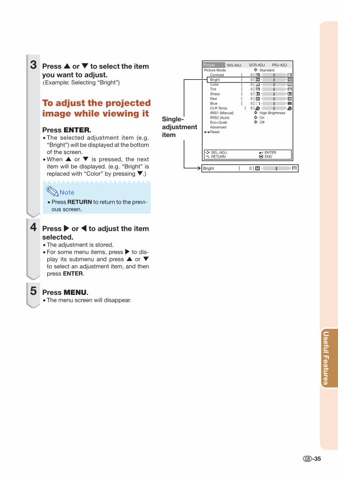
3 Press ' or " to select the item you want to adjust.(Example: Selecting “Bright”)
To adjust the projected image while viewing it
Press ENTER.• The selected adjustment item (e.g.
“Bright”) will be displayed at the bottom
of the screen.
• When ' or " is pressed, the next
item will be displayed. (e.g. “Bright” is
replaced with “Color” by pressing ".)
Note
• Press RETURN to return to the previ-
ous screen.
4 Press | or \ to adjust the item selected.• The adjustment is stored.
• For some menu items, press | to dis-
play its submenu and press ' or "
to select an adjustment item, and then
press ENTER.
5 Press MENU.• The menu screen will disappear.
Single-adjustment item
Bright 0
XV-Z15000_E_US.indb 35XV-Z15000_E_US.indb 35 2008/12/25 14:25:342008/12/25 14:25:34
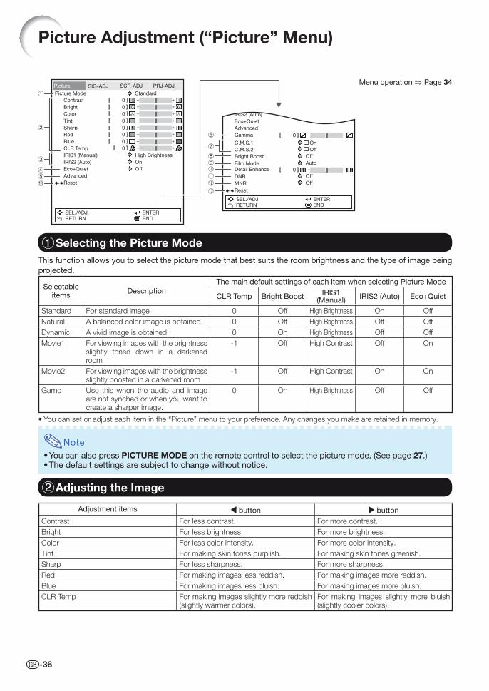
-36
Picture Adjustment (“Picture” Menu)
Menu operation ⇒ Page 34Picture
Picture Mode Standard
High Brightness
On
Off
Contrast
Bright
Color
Tint
Sharp
Red
Blue
CLR Temp
IRIS1 (Manual)
IRIS2 (Auto)
Eco+Quiet
Advanced
Reset
SEL./ADJ.RETURN
ENTEREND
SIG-ADJ SCR-ADJ PRJ-ADJ
0
0
0
0
0
0
0
0
Selectable items
Description
The main default settings of each item when selecting Picture Mode
CLR Temp Bright BoostIRIS1
(Manual)IRIS2 (Auto) Eco+Quiet
Standard For standard image 0 Off High Brightness On Off
Natural A balanced color image is obtained. 0 Off High Brightness Off Off
Dynamic A vivid image is obtained. 0 On High Brightness Off Off
Movie1 For viewing images with the brightness slightly toned down in a darkened room
-1 Off High Contrast Off On
Movie2 For viewing images with the brightness slightly boosted in a darkened room
-1 Off High Contrast On On
Game Use this when the audio and image are not synched or when you want to create a sharper image.
0 On High Brightness Off Off
• You can set or adjust each item in the “Picture” menu to your preference. Any changes you make are retained in memory.
Note
• You can also press PICTURE MODE on the remote control to select the picture mode. (See page 27.)• The default settings are subject to change without notice.
Adjustment items \ button | button
Contrast For less contrast. For more contrast.
Bright For less brightness. For more brightness.
Color For less color intensity. For more color intensity.
Tint For making skin tones purplish. For making skin tones greenish.
Sharp For less sharpness. For more sharpness.
Red For making images less reddish. For making images more reddish.
Blue For making images less bluish. For making images more bluish.
CLR Temp For making images slightly more reddish (slightly warmer colors).
For making images slightly more bluish (slightly cooler colors).
1 Selecting the Picture Mode
2 Adjusting the Image
This function allows you to select the picture mode that best suits the room brightness and the type of image being
projected.
IRIS2 (Auto)
Eco+Quiet
Advanced
Gamma
C.M.S.1 On
Off
Off
Auto
C.M.S.2
Bright Boost
Film ModeDetail Enhance
Reset
SEL./ADJ.RETURN
ENTEREND
0
0
Off
Off
DNR
MNR
XV-Z15000_E_US.indb 36XV-Z15000_E_US.indb 36 2008/12/25 14:25:352008/12/25 14:25:35
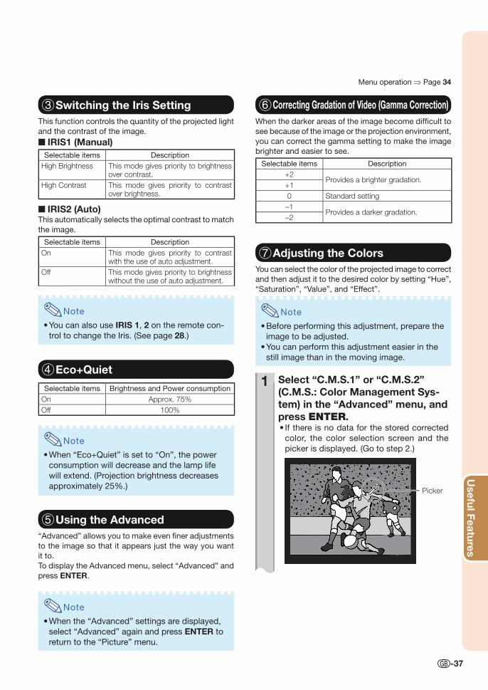
Useful Features
-37
3 Switching the Iris SettingThis function controls the quantity of the projected light
and the contrast of the image.
■ IRIS1 (Manual)Selectable items Description
High Brightness This mode gives priority to brightness over contrast.
High Contrast This mode gives priority to contrast over brightness.
■ IRIS2 (Auto)This automatically selects the optimal contrast to match
the image.
Selectable items Description
On This mode gives priority to contrast with the use of auto adjustment.
Off This mode gives priority to brightness without the use of auto adjustment.
Note
• You can also use IRIS 1, 2 on the remote con-
trol to change the Iris. (See page 28.)
4 Eco+Quiet
Selectable items Brightness and Power consumption
On Approx. 75%
Off 100%
Note
• When “Eco+Quiet” is set to “On”, the power
consumption will decrease and the lamp life
will extend. (Projection brightness decreases
approximately 25%.)
5 Using the Advanced“Advanced” allows you to make even fi ner adjustments
to the image so that it appears just the way you want
it to.
To display the Advanced menu, select “Advanced” and
press ENTER.
Note
• When the “Advanced” settings are displayed,
select “Advanced” again and press ENTER to
return to the “Picture” menu.
Menu operation ⇒ Page 34
6 Correcting Gradation of Video (Gamma Correction)When the darker areas of the image become diffi cult to
see because of the image or the projection environment,
you can correct the gamma setting to make the image
brighter and easier to see.
Selectable items Description
+2Provides a brighter gradation.
+1
0 Standard setting
–1Provides a darker gradation.
–2
7 Adjusting the ColorsYou can select the color of the projected image to correct
and then adjust it to the desired color by setting “Hue”,
“Saturation”, “Value”, and “Effect”.
Note
• Before performing this adjustment, prepare the
image to be adjusted.
• You can perform this adjustment easier in the
still image than in the moving image.
1 Select “C.M.S.1” or “C.M.S.2” (C.M.S.: Color Management Sys-tem) in the “Advanced” menu, and press ENTER.
If there is no data for the stored corrected
color, the color selection screen and the
picker is displayed. (Go to step 2.)
Picker
•
1
XV-Z15000_E_US.indb 37XV-Z15000_E_US.indb 37 2008/12/25 14:25:352008/12/25 14:25:35
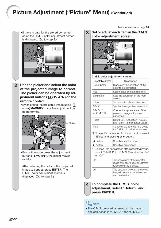
-38
If there is data for the stored corrected
color, the C.M.S. color adjustment screen
is displayed. (Go to step 3.)
C.M.S.1
Select Color
Hue
Saturation
Value
Effect
C.M.S.1 On
Reset
Return
SEL./ADJ.RETURN
ENTEREND
0
0
0
0
2 Use the picker and select the color of the projected image to correct. The picker can be operated by ad-justment buttons (P/R/O/Q) on the remote control.
By enlarging the projected image using
or MAGNIFY, more fi ne adjustment can
be performed.
Picker
By continuing to press the adjustment
buttons (P/R/O/Q), the picker moves
rapidly.
After selecting the color of the projected
image to correct, press ENTER. The
C.M.S. color adjustment screen is
displayed. (Go to step 3.)
•
•
•
2
Menu operation ⇒ Page 34
3 Set or adjust each item in the C.M.S. color adjustment screen.
C.M.S.1
Select Color
Hue
Saturation
Value
Effect
C.M.S.1 On
Reset
Return
SEL./ADJ.RETURN
ENTEREND
0
0
0
0
C.M.S. color adjustment screen:
Selectable items Description
Select Color Starts over the selection of the color to be corrected.
Hue Sets the hue of the main colors.
Saturation Sets the saturation of the main colors.
Value Sets the value of the main colors.
Effect*1 Specifi es the range of color correction.
C.M.S.1*2
(or C.M.S.2)Checks the appearance of the projected image after above correction.
Reset Sets “Hue”, “Saturation”, “Value”, and “Effect” to their default values.
Return Completes the correction and closes the C.M.S. color adjustment screen.
*1 To specify the range of color correction, select
“Effect” and press O or Q button.
O button Specifi es smaller range.
Q button Specifi es larger range.
*2 To check the appearance of the projected image,
select “C.M.S.1” (or “C.M.S.2”) and set to “On”
or “Off”.
On The appearance of the projected image after above color adjustment refl ected can be checked.
Off The appearance of the projected image in former color adjustment can be checked.
4 To complete the C.M.S. color adjustment, select “Return” and press ENTER.
Note
• The C.M.S. color adjustment can be made to
one color each in “C.M.S.1” and “C.M.S.2”.
3
4
Picture Adjustment (“Picture” Menu) (Continued)
XV-Z15000_E_US.indb 38XV-Z15000_E_US.indb 38 2008/12/25 14:25:372008/12/25 14:25:37
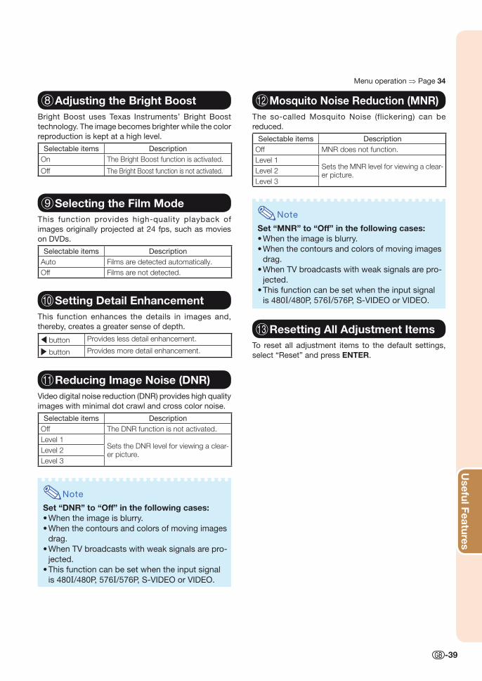
Useful Features
-39
8 Adjusting the Bright BoostBright Boost uses Texas Instruments’ Bright Boost
technology. The image becomes brighter while the color
reproduction is kept at a high level.
Selectable items Description
On The Bright Boost function is activated.
Off The Bright Boost function is not activated.
9 Selecting the Film ModeThis function provides high-quality playback of
images originally projected at 24 fps, such as movies
on DVDs.
Selectable items Description
Auto Films are detected automatically.
Off Films are not detected.
0 Setting Detail EnhancementThis function enhances the details in images and,
thereby, creates a greater sense of depth.
\ button Provides less detail enhancement.
| button Provides more detail enhancement.
q Reducing Image Noise (DNR)Video digital noise reduction (DNR) provides high quality
images with minimal dot crawl and cross color noise.
Selectable items Description
Off The DNR function is not activated.
Level 1Sets the DNR level for viewing a clear-er picture.
Level 2
Level 3
Note
Set “DNR” to “Off” in the following cases:• When the image is blurry.
• When the contours and colors of moving images
drag.
• When TV broadcasts with weak signals are pro-
jected.
• This function can be set when the input signal
is 480I/480P, 576I/576P, S-VIDEO or VIDEO.
Menu operation ⇒ Page 34
w Mosquito Noise Reduction (MNR)The so-called Mosquito Noise (flickering) can be
reduced.
Selectable items Description
Off MNR does not function.
Level 1Sets the MNR level for viewing a clear-er picture.
Level 2
Level 3
Note
Set “MNR” to “Off” in the following cases:• When the image is blurry.
• When the contours and colors of moving images
drag.
• When TV broadcasts with weak signals are pro-
jected.
• This function can be set when the input signal
is 480I/480P, 576I/576P, S-VIDEO or VIDEO.
e Resetting All Adjustment ItemsTo reset all adjustment items to the default settings,
select “Reset” and press ENTER.
XV-Z15000_E_US.indb 39XV-Z15000_E_US.indb 39 2008/12/25 14:25:372008/12/25 14:25:37
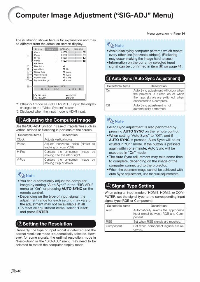
-40
Computer Image Adjustment (“SIG-ADJ” Menu)
Menu operation ⇒ Page 34
The illustration shown here is for explanation and may be different from the actual on-screen display.
Picture
Clock
Phase
H-Pos
V-Pos
Reset
Resolution
Auto Sync On
Auto
Auto
0 IRE
Auto
Signal Type
Signal Info : 1080P
H : XX.X kHz/ V : XX.X Hz
Video System
Video Setup
Dynamic Range
SEL./ADJ.RETURN
ENTEREND
SIG-ADJ SCR-ADJ PRJ-ADJ
0
0
0
0
*1
*2
*1 If the input mode is S-VIDEO or VIDEO input, the display changes to the “Video System” screen.
*2 Displayed when the input mode is HDMI input.
1 Adjusting the Computer ImageUse the SIG-ADJ function in case of irregularities such as vertical stripes or fl ickering in portions of the screen.
Selectable items Description
Clock Adjusts vertical noise.
Phase Adjusts horizontal noise (similar to tracking on your VCR).
H-Pos Centers the on-screen image by moving it to the left or right.
V-Pos Centers the on-screen image by moving it up or down.
Note
• You can automatically adjust the computer image by setting “Auto Sync” in the “SIG-ADJ” menu to “On”, or pressing AUTO SYNC on the remote control.
• Depending on the type of input signal, the adjustment range for each setting may vary or the adjustment may not be available at all.
• To reset all adjustment items, select “Reset” and press ENTER.
2 Setting the ResolutionOrdinarily, the type of input signal is detected and the correct resolution mode is automatically selected. How-ever, for some signals, the optimal resolution mode in “Resolution” in the “SIG-ADJ” menu may need to be selected to match the computer display mode.
Note
• Avoid displaying computer patterns which repeat every other line (horizontal stripes). (Flickering may occur, making the image hard to see.)
• Information on the currently selected input signal can be confi rmed in item 8 on page 41.
3 Auto Sync (Auto Sync Adjustment)
Selectable items Description
On Auto Sync adjustment will occur when the projector is turned on or when the input signals are switched, when connected to a computer.
Off Auto Sync adjustment is not automatically performed.
Note
• Auto Sync adjustment is also performed by
pressing AUTO SYNC on the remote control.
• When setting “Auto Sync” to “Off”, and if
AUTO SYNC is pressed, Auto Sync will be ex-
ecuted in “On” mode. If the button is pressed
again within one minute, Auto Sync will be
executed in “On” mode.
• The Auto Sync adjustment may take some time
to complete, depending on the image of the
computer connected to the projector.
• When the optimum image cannot be achieved with
Auto Sync adjustment, use manual adjustments.
4 Signal Type SettingWhen using an input mode of HDMI1, HDMI2, or COM-
PUTER, set the signal type to the corresponding input
signal type (RGB or Component).
Selectable items Description
Auto Automatically selects the appropriate input signal between RGB and Com-ponent.
RGB Set when RGB signals are received.
Component Set when component signals are re-ceived.
XV-Z15000_E_US.indb 40XV-Z15000_E_US.indb 40 2008/12/25 14:25:382008/12/25 14:25:38
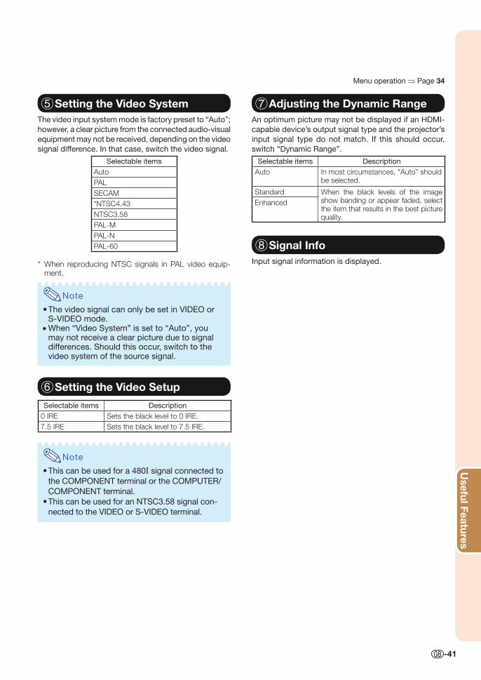
Useful Features
-41
5 Setting the Video SystemThe video input system mode is factory preset to “Auto”;
however, a clear picture from the connected audio-visual
equipment may not be received, depending on the video
signal difference. In that case, switch the video signal.
Selectable items
Auto
PAL
SECAM
*NTSC4.43
NTSC3.58
PAL-M
PAL-N
PAL-60
* When reproducing NTSC signals in PAL video equip-ment.
Note
• The video signal can only be set in VIDEO or S-VIDEO mode.
• When “Video System” is set to “Auto”, you may not receive a clear picture due to signal differences. Should this occur, switch to the video system of the source signal.
6 Setting the Video Setup
Selectable items Description
0 IRE Sets the black level to 0 IRE.
7.5 IRE Sets the black level to 7.5 IRE.
Note
• This can be used for a 480I signal connected to
the COMPONENT terminal or the COMPUTER/
COMPONENT terminal.
• This can be used for an NTSC3.58 signal con-
nected to the VIDEO or S-VIDEO terminal.
7 Adjusting the Dynamic RangeAn optimum picture may not be displayed if an HDMI-
capable device’s output signal type and the projector’s
input signal type do not match. If this should occur,
switch “Dynamic Range”.
Selectable items Description
Auto In most circumstances, “Auto” should be selected.
Standard When the black levels of the image show banding or appear faded, select the item that results in the best picture quality.
Enhanced
8 Signal InfoInput signal information is displayed.
Menu operation ⇒ Page 34
XV-Z15000_E_US.indb 41XV-Z15000_E_US.indb 41 2008/12/25 14:25:382008/12/25 14:25:38
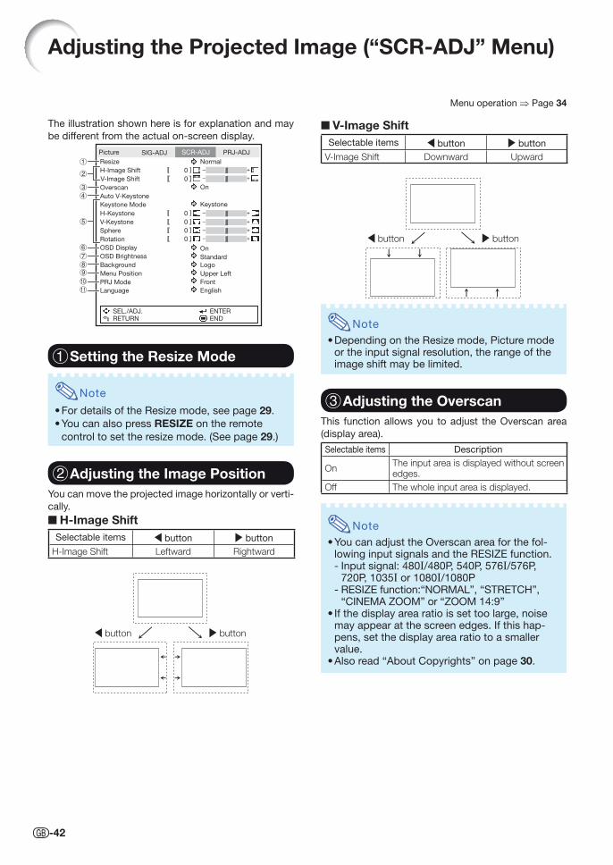
-42
Adjusting the Projected Image (“SCR-ADJ” Menu)
Menu operation ⇒ Page 34
The illustration shown here is for explanation and may
be different from the actual on-screen display.
Picture
Resize Normal
On
On
Standard
Logo
Upper Left
Front
English
Keystone
H-Image Shift
V-Image Shift
Overscan
Auto V-Keystone
Keystone Mode
H-Keystone
V-Keystone
Sphere
Rotation
OSD Display
OSD Brightness
Background
Menu Position
PRJ Mode
Language
SEL./ADJ.RETURN
ENTEREND
SIG-ADJ SCR-ADJ PRJ-ADJ
0
0
0
0
0
0
1 Setting the Resize Mode
Note
• For details of the Resize mode, see page 29.
• You can also press RESIZE on the remote
control to set the resize mode. (See page 29.)
2 Adjusting the Image PositionYou can move the projected image horizontally or verti-
cally.
■ H-Image ShiftSelectable items \ button | button
H-Image Shift Leftward Rightward
| button\ button
■ V-Image ShiftSelectable items \ button | button
V-Image Shift Downward Upward
| button\ button
Note
• Depending on the Resize mode, Picture mode or the input signal resolution, the range of the image shift may be limited.
3 Adjusting the OverscanThis function allows you to adjust the Overscan area
(display area).
Selectable items Description
OnThe input area is displayed without screen edges.
Off The whole input area is displayed.
Note
• You can adjust the Overscan area for the fol-lowing input signals and the RESIZE function.- Input signal: 480I/480P, 540P, 576I/576P,
720P, 1035I or 1080I/1080P- RESIZE function:“NORMAL”, “STRETCH”,
“CINEMA ZOOM” or “ZOOM 14:9” • If the display area ratio is set too large, noise
may appear at the screen edges. If this hap-pens, set the display area ratio to a smaller value.
• Also read “About Copyrights” on page 30.
XVZ15000_E_US_07.indd 42XVZ15000_E_US_07.indd 42 2009/01/16 17:38:152009/01/16 17:38:15
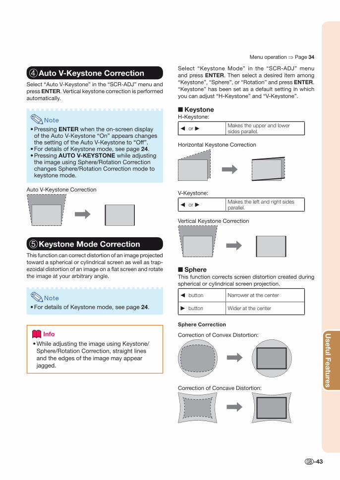
Useful Features
-43
4 Auto V-Keystone CorrectionSelect “Auto V-Keystone” in the “SCR-ADJ” menu and
press ENTER. Vertical keystone correction is performed
automatically.
Note
• Pressing ENTER when the on-screen display of the Auto V-Keystone “On” appears changes the setting of the Auto V-Keystone to “Off”.
• For details of Keystone mode, see page 24.• Pressing AUTO V-KEYSTONE while adjusting
the image using Sphere/Rotation Correction changes Sphere/Rotation Correction mode to keystone mode.
Auto V-Keystone Correction
5 Keystone Mode CorrectionThis function can correct distortion of an image projected
toward a spherical or cylindrical screen as well as trap-
ezoidal distortion of an image on a fl at screen and rotate
the image at your arbitrary angle.
Note
• For details of Keystone mode, see page 24.
Info
While adjusting the image using Keystone/
Sphere/Rotation Correction, straight lines
and the edges of the image may appear
jagged.
•
Select “Keystone Mode” in the “SCR-ADJ” menu
and press ENTER. Then select a desired item among
“Keystone”, “Sphere”, or “Rotation” and press ENTER.
“Keystone” has been set as a default setting in which
you can adjust “H-Keystone” and “V-Keystone”.
■ KeystoneH-Keystone:
O or Q Makes the upper and lower sides parallel.
Horizontal Keystone Correction
V-Keystone:
O or Q Makes the left and right sides parallel.
Vertical Keystone Correction
■ SphereThis function corrects screen distortion created during
spherical or cylindrical screen projection.
O button Narrower at the center
Q button Wider at the center
Sphere Correction
Correction of Convex Distortion:
Correction of Concave Distortion:
Menu operation ⇒ Page 34
XV-Z15000_E_US.indb 43XV-Z15000_E_US.indb 43 2008/12/25 14:25:392008/12/25 14:25:39
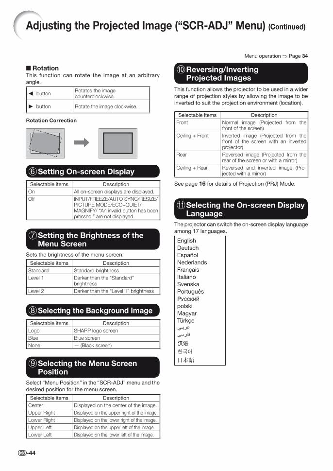
-44
Menu operation ⇒ Page 34
■ RotationThis function can rotate the image at an arbitrary
angle.
O buttonRotates the image counterclockwise.
Q button Rotate the image clockwise.
Rotation Correction
6 Setting On-screen Display
Selectable items Description
On All on-screen displays are displayed.
Off INPUT/FREEZE/AUTO SYNC/RESIZE/PICTURE MODE/ECO+QUIET/MAGNIFY/ “An invalid button has been pressed.” are not displayed.
7 Setting the Brightness of the Menu Screen
Sets the brightness of the menu screen.
Selectable items Description
Standard Standard brightness
Level 1 Darker than the “Standard” brightness
Level 2 Darker than the “Level 1” brightness
8 Selecting the Background Image
Selectable items Description
Logo SHARP logo screen
Blue Blue screen
None — (Black screen)
9 Selecting the Menu Screen Position
Select “Menu Position” in the “SCR-ADJ” menu and the
desired position for the menu screen.
Selectable items Description
Center Displayed on the center of the image.
Upper Right Displayed on the upper right of the image.
Lower Right Displayed on the lower right of the image.
Upper Left Displayed on the upper left of the image.
Lower Left Displayed on the lower left of the image.
0 Reversing/Inverting Projected Images
This function allows the projector to be used in a wider
range of projection styles by allowing the image to be
inverted to suit the projection environment (location).
Selectable items Description
Front Normal image (Projected from the front of the screen)
Ceiling + Front Inverted image (Projected from the front of the screen with an inverted projector)
Rear Reversed image (Projected from the rear of the screen or with a mirror)
Ceiling + Rear Reversed and inverted image (Pro-jected with a mirror)
See page 16 for details of Projection (PRJ) Mode.
q Selecting the On-screen Display Language
The projector can switch the on-screen display language
among 17 languages.
English
Deutsch
Español
Nederlands
Français
Italiano
Svenska
Português
polski
Magyar
Türkçe
Adjusting the Projected Image (“SCR-ADJ” Menu) (Continued)
XV-Z15000_E_US.indb 44XV-Z15000_E_US.indb 44 2008/12/25 14:25:402008/12/25 14:25:40
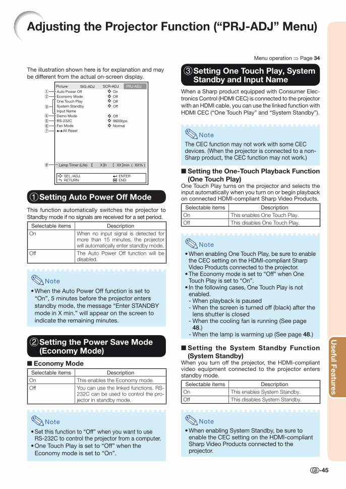
Useful Features
-45
Adjusting the Projector Function (“PRJ-ADJ” Menu)
3 Setting One Touch Play, System Standby and Input Name
When a Sharp product equipped with Consumer Elec-
tronics Control (HDMI CEC) is connected to the projector
with an HDMI cable, you can use the linked function with
HDMI CEC (“One Touch Play” and “System Standby”).
Note
The CEC function may not work with some CEC devices. (When the projector is connected to a non-Sharp product, the CEC function may not work.)
■ Setting the One-Touch Playback Function (One Touch Play)
One Touch Play turns on the projector and selects the input automatically when you turn on or begin playback on connected HDMI-compliant Sharp Video Products.
Selectable items Description
On This enables One Touch Play.
Off This disables One Touch Play.
Note
• When enabling One Touch Play, be sure to enable the CEC setting on the HDMI-compliant Sharp Video Products connected to the projector.
• The Economy mode is set to “Off” when One Touch Play is set to “On”.
• In the following cases, One Touch Play is not enabled.- When playback is paused- When the screen is turned off (black) after the
lens shutter is closed- When the cooling fan is running (See page
48.)- When the lamp is warming up (See page 48.)
■ Setting the System Standby Function (System Standby)
When you turn off the projector, the HDMI-compliant video equipment connected to the projector enters standby mode.
Selectable items Description
On This enables System Standby.
Off This disables System Standby.
Note
• When enabling System Standby, be sure to enable the CEC setting on the HDMI-compliant Sharp Video Products connected to the projector.
1 Setting Auto Power Off Mode
This function automatically switches the projector to
Standby mode if no signals are received for a set period.
Selectable items Description
On When no input signal is detected for more than 15 minutes, the projector will automatically enter standby mode.
Off The Auto Power Off function will be disabled.
Note
• When the Auto Power Off function is set to
“On”, 5 minutes before the projector enters
standby mode, the message “Enter STANDBY
mode in X min.” will appear on the screen to
indicate the remaining minutes.
2 Setting the Power Save Mode (Economy Mode)
■ Economy ModeSelectable items Description
On This enables the Economy mode.
Off You can use the linked functions. RS-232C can be used to control the pro-jector in standby mode.
Note
• Set this function to “Off” when you want to use RS-232C to control the projector from a computer.
• One Touch Play is set to “Off” when the
Economy mode is set to “On”.
The illustration shown here is for explanation and may
be different from the actual on-screen display.
Picture
Auto Power Off On
Off
Off
Off
Off
9600bps
Normal
Economy Mode
One Touch Play
System Standby
Input Name
Demo Mode
RS-232C
Fan Mode
Lamp Timer (Life) min ( )
All Reset
SEL./ADJ.RETURN
ENTEREND
SIG-ADJ SCR-ADJ PRJ-ADJ
hX XX XX%
Menu operation ⇒ Page 34
XVZ15000_E_US_07.indd 45XVZ15000_E_US_07.indd 45 2009/01/14 15:42:432009/01/14 15:42:43
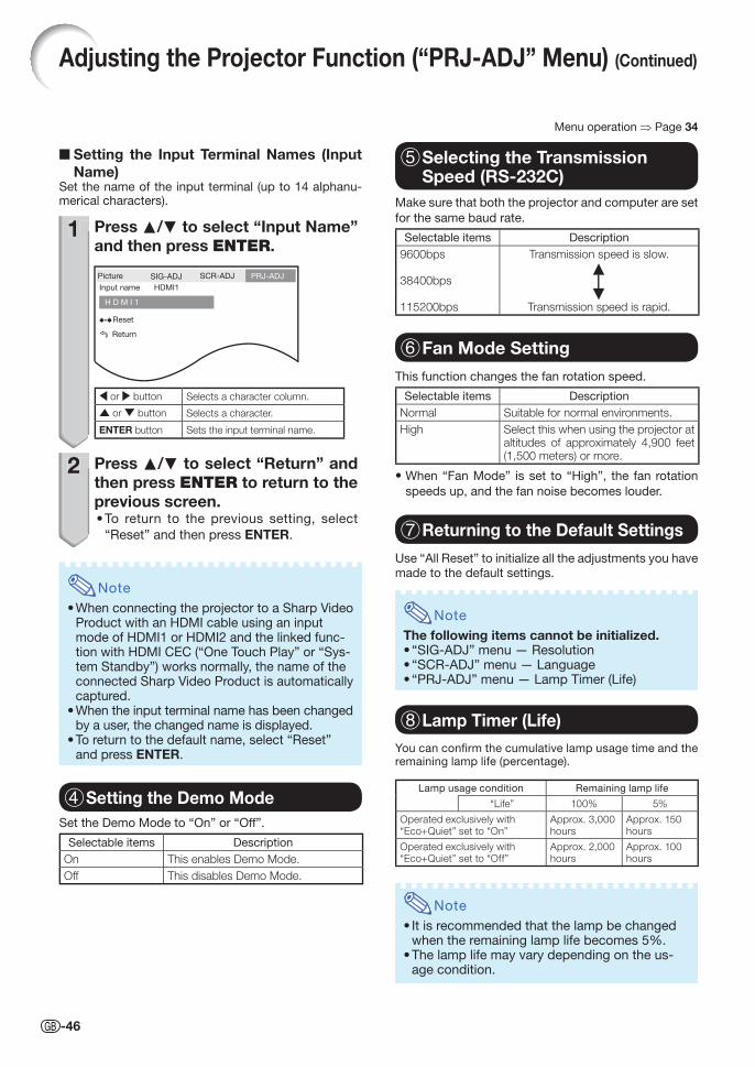
-46
5 Selecting the Transmission Speed (RS-232C)
6 Fan Mode Setting
■ Setting the Input Terminal Names (Input Name)
Set the name of the input terminal (up to 14 alphanu-merical characters).
1 Press P/R to select “Input Name” and then press ENTER.
Picture
Input name
H D M I 1
HDMI1
Reset
Return
SIG-ADJ SCR-ADJ PRJ-ADJ
\ or | button Selects a character column.
▼ or 、 button Selects a character.
ENTER button Sets the input terminal name.
2 Press P/R to select “Return” and then press ENTER to return to the previous screen.
To return to the previous setting, select
“Reset” and then press ENTER.
Note
• When connecting the projector to a Sharp Video Product with an HDMI cable using an input mode of HDMI1 or HDMI2 and the linked func-tion with HDMI CEC (“One Touch Play” or “Sys-tem Standby”) works normally, the name of the connected Sharp Video Product is automatically captured.
• When the input terminal name has been changed by a user, the changed name is displayed.
• To return to the default name, select “Reset” and press ENTER.
4 Setting the Demo ModeSet the Demo Mode to “On” or “Off”.
Selectable items Description
On This enables Demo Mode.
Off This disables Demo Mode.
•
1
2
7 Returning to the Default Settings
8 Lamp Timer (Life)You can confi rm the cumulative lamp usage time and the remaining lamp life (percentage).
Lamp usage condition Remaining lamp life
“Life” 100% 5%
Operated exclusively with “Eco+Quiet” set to “On”
Approx. 3,000 hours
Approx. 150 hours
Operated exclusively with “Eco+Quiet” set to “Off”
Approx. 2,000 hours
Approx. 100 hours
Note
• It is recommended that the lamp be changed when the remaining lamp life becomes 5%.
• The lamp life may vary depending on the us-age condition.
Make sure that both the projector and computer are set
for the same baud rate.
Selectable items Description
9600bps
38400bps
115200bps
Transmission speed is slow.
Transmission speed is rapid.
This function changes the fan rotation speed.
Selectable items Description
Normal Suitable for normal environments.
High Select this when using the projector at altitudes of approximately 4,900 feet (1,500 meters) or more.
• When “Fan Mode” is set to “High”, the fan rotation
speeds up, and the fan noise becomes louder.
Use “All Reset” to initialize all the adjustments you have
made to the default settings.
Note
The following items cannot be initialized.• “SIG-ADJ” menu — Resolution• “SCR-ADJ” menu — Language• “PRJ-ADJ” menu — Lamp Timer (Life)
Menu operation ⇒ Page 34
Adjusting the Projector Function (“PRJ-ADJ” Menu) (Continued)
XVZ15000_E_US_07.indd 46XVZ15000_E_US_07.indd 46 2009/01/14 15:42:442009/01/14 15:42:44
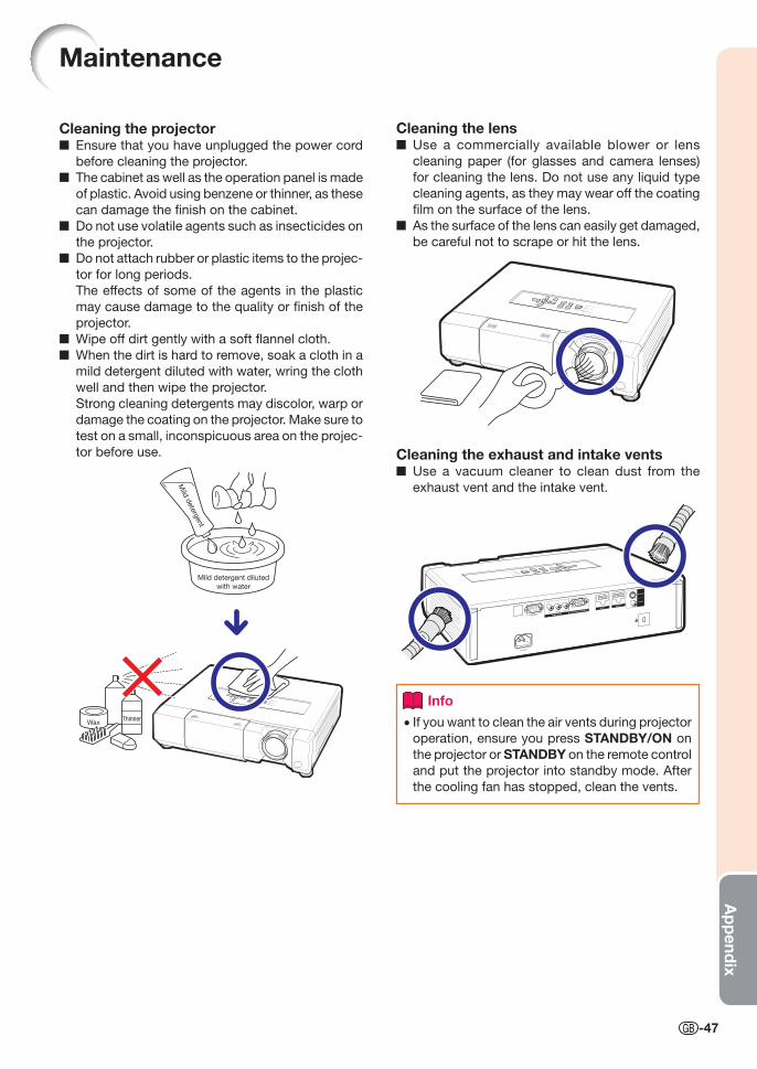
Ap
pend
ix
-47
Cleaning the projector■ Ensure that you have unplugged the power cord
before cleaning the projector.
■ The cabinet as well as the operation panel is made
of plastic. Avoid using benzene or thinner, as these
can damage the fi nish on the cabinet.
■ Do not use volatile agents such as insecticides on
the projector.
■ Do not attach rubber or plastic items to the projec-
tor for long periods.
The effects of some of the agents in the plastic
may cause damage to the quality or fi nish of the
projector.
■ Wipe off dirt gently with a soft fl annel cloth.
■ When the dirt is hard to remove, soak a cloth in a
mild detergent diluted with water, wring the cloth
well and then wipe the projector.
Strong cleaning detergents may discolor, warp or
damage the coating on the projector. Make sure to
test on a small, inconspicuous area on the projec-
tor before use.
Mild
dete
rgent
Mild detergent diluted
with water
ThinnerWax
Maintenance
Cleaning the lens■ Use a commercially available blower or lens
cleaning paper (for glasses and camera lenses)
for cleaning the lens. Do not use any liquid type
cleaning agents, as they may wear off the coating
fi lm on the surface of the lens.
■ As the surface of the lens can easily get damaged,
be careful not to scrape or hit the lens.
Cleaning the exhaust and intake vents■ Use a vacuum cleaner to clean dust from the
exhaust vent and the intake vent.
Info
• If you want to clean the air vents during projector
operation, ensure you press STANDBY/ON on
the projector or STANDBY on the remote control
and put the projector into standby mode. After
the cooling fan has stopped, clean the vents.
XV-Z15000_E_US.indb 47XV-Z15000_E_US.indb 47 2008/12/25 14:25:422008/12/25 14:25:42
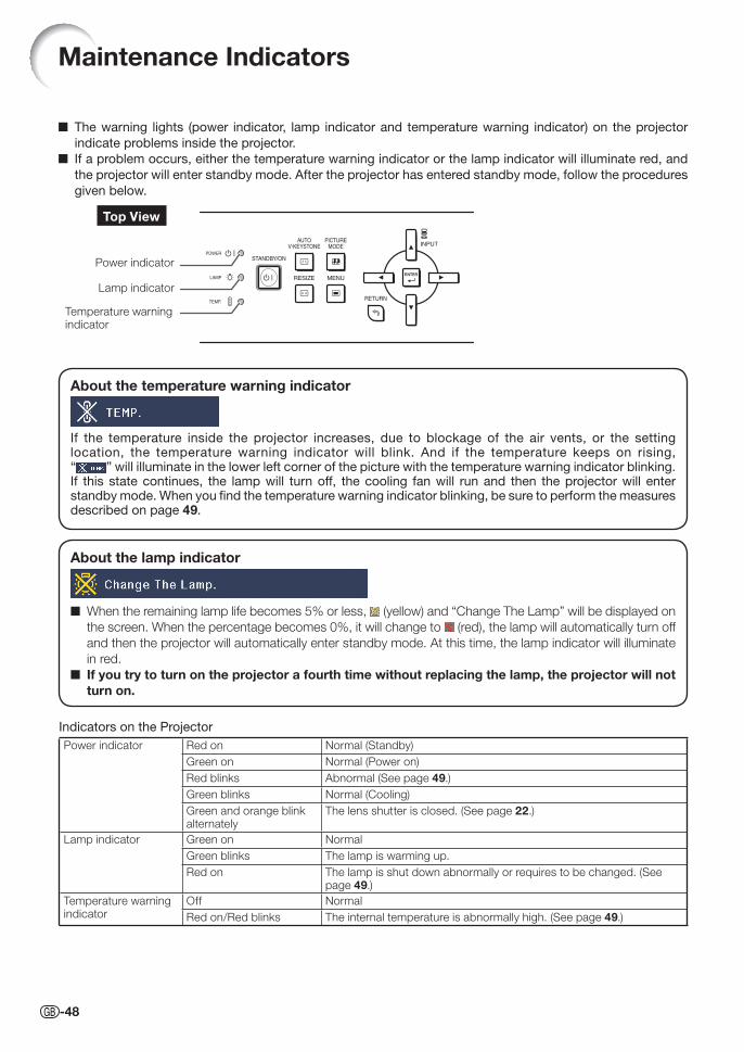
-48
About the temperature warning indicator
If the temperature inside the projector increases, due to blockage of the air vents, or the setting location, the temperature warning indicator will blink. And if the temperature keeps on rising, “ ” will illuminate in the lower left corner of the picture with the temperature warning indicator blinking. If this state continues, the lamp will turn off, the cooling fan will run and then the projector will enter standby mode. When you fi nd the temperature warning indicator blinking, be sure to perform the measures described on page 49.
Maintenance Indicators
■ The warning lights (power indicator, lamp indicator and temperature warning indicator) on the projector
indicate problems inside the projector.
■ If a problem occurs, either the temperature warning indicator or the lamp indicator will illuminate red, and
the projector will enter standby mode. After the projector has entered standby mode, follow the procedures
given below.
Top View
Lamp indicator
Temperature warning indicator
Power indicator
About the lamp indicator
■ When the remaining lamp life becomes 5% or less, (yellow) and “Change The Lamp” will be displayed on
the screen. When the percentage becomes 0%, it will change to (red), the lamp will automatically turn off
and then the projector will automatically enter standby mode. At this time, the lamp indicator will illuminate
in red.
■ If you try to turn on the projector a fourth time without replacing the lamp, the projector will not turn on.
Indicators on the Projector
Power indicator Red on Normal (Standby)
Green on Normal (Power on)
Red blinks Abnormal (See page 49.)
Green blinks Normal (Cooling)
Green and orange blink alternately
The lens shutter is closed. (See page 22.)
Lamp indicator Green on Normal
Green blinks The lamp is warming up.
Red on The lamp is shut down abnormally or requires to be changed. (See page 49.)
Temperature warning indicator
Off Normal
Red on/Red blinks The internal temperature is abnormally high. (See page 49.)
XV-Z15000_E_US.indb 48XV-Z15000_E_US.indb 48 2008/12/25 14:25:432008/12/25 14:25:43
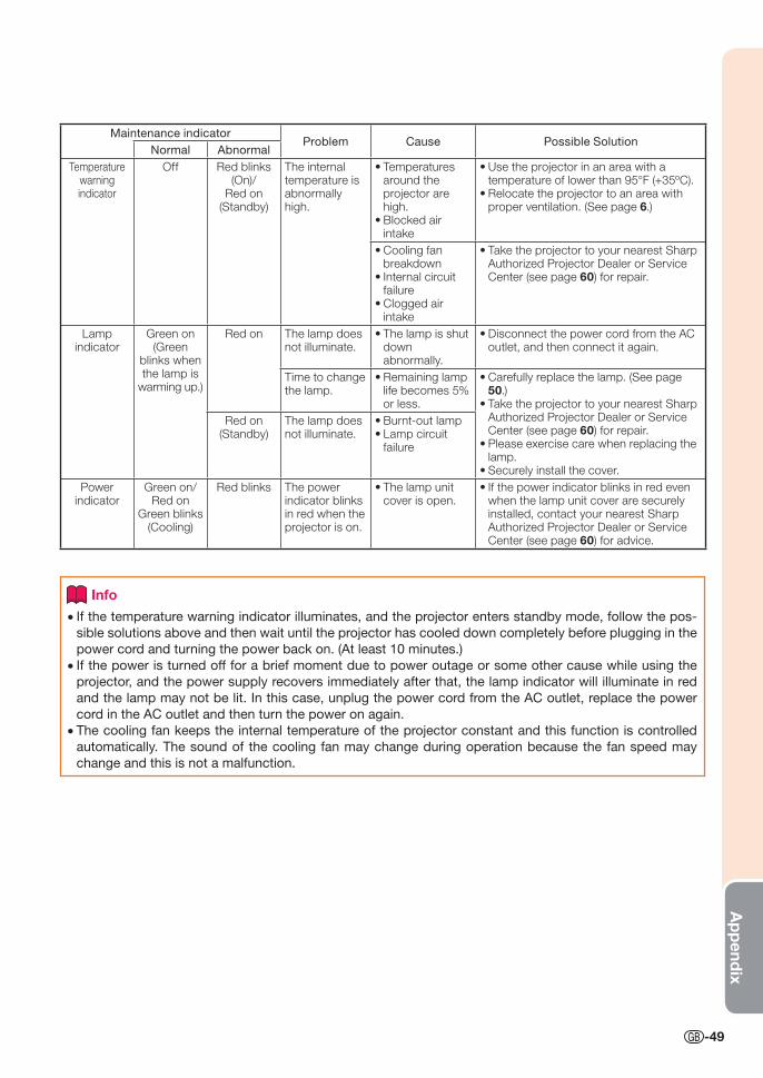
Ap
pend
ix
-49
Maintenance indicatorProblem Cause Possible Solution
Normal Abnormal
Temperature warning indicator
Off Red blinks (On)/
Red on (Standby)
The internal temperature is abnormally high.
Temperatures around the projector are high.Blocked air intake
•
•
Use the projector in an area with a temperature of lower than 95°F (+35ºC).Relocate the projector to an area with proper ventilation. (See page 6.)
•
•
Cooling fan breakdownInternal circuit failureClogged air intake
•
•
•
Take the projector to your nearest Sharp Authorized Projector Dealer or Service Center (see page 60) for repair.
•
Lamp indicator
Green on (Green
blinks when the lamp is
warming up.)
Red on The lamp does not illuminate.
The lamp is shut down abnormally.
• Disconnect the power cord from the AC outlet, and then connect it again.
•
Time to change the lamp.
Remaining lamp life becomes 5% or less.
• Carefully replace the lamp. (See page 50.)Take the projector to your nearest Sharp Authorized Projector Dealer or Service Center (see page 60) for repair.Please exercise care when replacing the lamp.Securely install the cover.
•
•
•
•
Red on (Standby)
The lamp does not illuminate.
Burnt-out lampLamp circuit failure
••
Power indicator
Green on/Red on
Green blinks (Cooling)
Red blinks The power indicator blinks in red when the projector is on.
The lamp unit cover is open.
• If the power indicator blinks in red even when the lamp unit cover are securely installed, contact your nearest Sharp Authorized Projector Dealer or Service Center (see page 60) for advice.
•
Info
• If the temperature warning indicator illuminates, and the projector enters standby mode, follow the pos-
sible solutions above and then wait until the projector has cooled down completely before plugging in the
power cord and turning the power back on. (At least 10 minutes.)
• If the power is turned off for a brief moment due to power outage or some other cause while using the
projector, and the power supply recovers immediately after that, the lamp indicator will illuminate in red
and the lamp may not be lit. In this case, unplug the power cord from the AC outlet, replace the power
cord in the AC outlet and then turn the power on again.
• The cooling fan keeps the internal temperature of the projector constant and this function is controlled
automatically. The sound of the cooling fan may change during operation because the fan speed may
change and this is not a malfunction.
XV-Z15000_E_US.indb 49XV-Z15000_E_US.indb 49 2008/12/25 14:25:442008/12/25 14:25:44
-50
Lamp■ It is recommended that the lamp (sold separately) be replaced when the remaining lamp life becomes
5% or less, or when you notice a signifi cant deterioration in the picture and color quality. The lamp life (percentage) can be checked with the on-screen display. (See page 46.)
■ Purchase a replacement lamp of type AN-K15LP from your place of purchase, nearest Sharp Autho-rized Projector Dealer or Service Center.
IMPORTANT NOTE TO U.S. CUSTOMERS:The lamp included with this projector is backed by a 90-day parts and labor limited warranty. All service
of this projector under warranty, including lamp replacement, must be obtained through a Sharp Autho-
rized Projector Dealer or Service Center. For the name of the nearest Sharp Authorized Projector Dealer
or Service Center, please call toll-free: 1-888-GO-SHARP (1-888-467-4277).
Hg LAMP CONTAINS MERCURY For State Lamp Disposal Information
www.lamprecycle.org or 1-800-BE-SHARP
Caution Concerning the Lamp■ This projector utilizes a pressurized mercury lamp. A loud sound may indicate lamp failure. Lamp
failure can be attributed to numerous sources such as: excessive shock, improper cooling, surface scratches or deterioration of the lamp due to a lapse of usage time.
■ The period of time up to failure largely varies depending on the individual lamp and/or the condition and the frequency of use. It is important to note that failure can often result in the bulb cracking.
■ When the lamp replacement indicator and on-screen display icon are illuminated, it is recommended that the lamp be replaced with a new one immediately, even if the lamp appears to be operating normally.
■ Should the lamp break, there is also a possibility that glass particles may spread inside of the projec-tor. In such a case, it is recommended you contact your nearest Sharp Authorized Projector Dealer or Service Center to assure safe operation.
■ Should the lamp break, the glass particles may spread inside the lamp cage or gas contained in the lamp may be vented into the room from the exhaust vent. Because the gas in this lamp includes mer-cury, ventilate the room well if the lamp breaks and avoid all exposure to the released gas. In case of exposure to the gas, consult a doctor as soon as possible.
Replacing the Lamp
Caution
• Do not remove the lamp unit from the projector right after use. The lamp will be very hot and may cause burns
or injury.
• Wait at least one hour after the power cord is disconnected to allow the surface of the lamp unit to fully cool
before removing the lamp unit.
■ Carefully change the lamp by following the instructions described in this section. * If you wish, you may have the lamp replaced at your nearest Sharp Authorized Projector Dealer or Service Center.
* If the new lamp does not light after replacement, take your projector to the nearest Sharp Authorized Projector
Dealer or Service Center for repair.
U.S.A. ONLY
Regarding the Lamp
XV-Z15000_E_US.indb 50XV-Z15000_E_US.indb 50 2008/12/25 14:25:442008/12/25 14:25:44
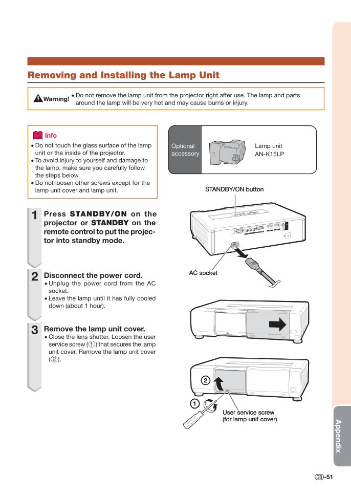
Ap
pend
ix
-51
Info
• Do not touch the glass surface of the lamp
unit or the inside of the projector.
• To avoid injury to yourself and damage to
the lamp, make sure you carefully follow
the steps below.
• Do not loosen other screws except for the
lamp unit cover and lamp unit.
1 Press STANDBY/ON on the projector or STANDBY on the remote control to put the projec-tor into standby mode.
2 Disconnect the power cord.• Unplug the power cord from the AC
socket.
• Leave the lamp until it has fully cooled
down (about 1 hour).
3 Remove the lamp unit cover.• Close the lens shutter. Loosen the user
service screw (1) that secures the lamp
unit cover. Remove the lamp unit cover
(2).
AC socket
STANDBY/ON button
AC socket
STANDBY/ON button
1
2
User service screw (for lamp unit cover)
1
2
User service screw (for lamp unit cover)
Removing and Installing the Lamp Unit
Warning! • Do not remove the lamp unit from the projector right after use. The lamp and parts
around the lamp will be very hot and may cause burns or injury.
Lamp unit
AN-K15LP
Optional
accessory
XV-Z15000_E_US.indb 51XV-Z15000_E_US.indb 51 2008/12/25 14:25:452008/12/25 14:25:45
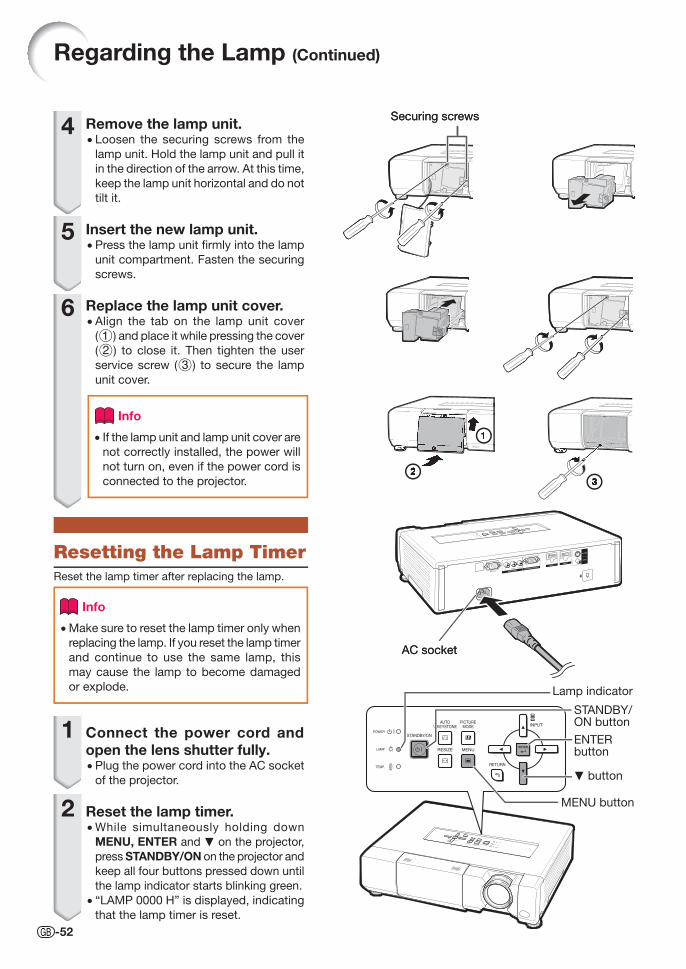
-52
4 Remove the lamp unit.• Loosen the securing screws from the
lamp unit. Hold the lamp unit and pull it
in the direction of the arrow. At this time,
keep the lamp unit horizontal and do not
tilt it.
5 Insert the new lamp unit.• Press the lamp unit fi rmly into the lamp
unit compartment. Fasten the securing
screws.
6 Replace the lamp unit cover.• Align the tab on the lamp unit cover
(1) and place it while pressing the cover
(2) to close it. Then tighten the user
service screw (3) to secure the lamp
unit cover.
Info
• If the lamp unit and lamp unit cover are
not correctly installed, the power will
not turn on, even if the power cord is
connected to the projector.
Resetting the Lamp TimerReset the lamp timer after replacing the lamp.
Info
• Make sure to reset the lamp timer only when
replacing the lamp. If you reset the lamp timer
and continue to use the same lamp, this
may cause the lamp to become damaged
or explode.
1 Connect the power cord and open the lens shutter fully.• Plug the power cord into the AC socket
of the projector.
2 Reset the lamp timer.• While simultaneously holding down
MENU, ENTER and R on the projector,
press STANDBY/ON on the projector and
keep all four buttons pressed down until
the lamp indicator starts blinking green.
• “LAMP 0000 H” is displayed, indicating
that the lamp timer is reset.
Securing screwsSecuring screws
11
2233
AC socketAC socket
Regarding the Lamp (Continued)
Lamp indicator
STANDBY/ON button
R button
ENTER button
MENU button
XV-Z15000_E_US.indb 52XV-Z15000_E_US.indb 52 2008/12/25 14:25:462008/12/25 14:25:46
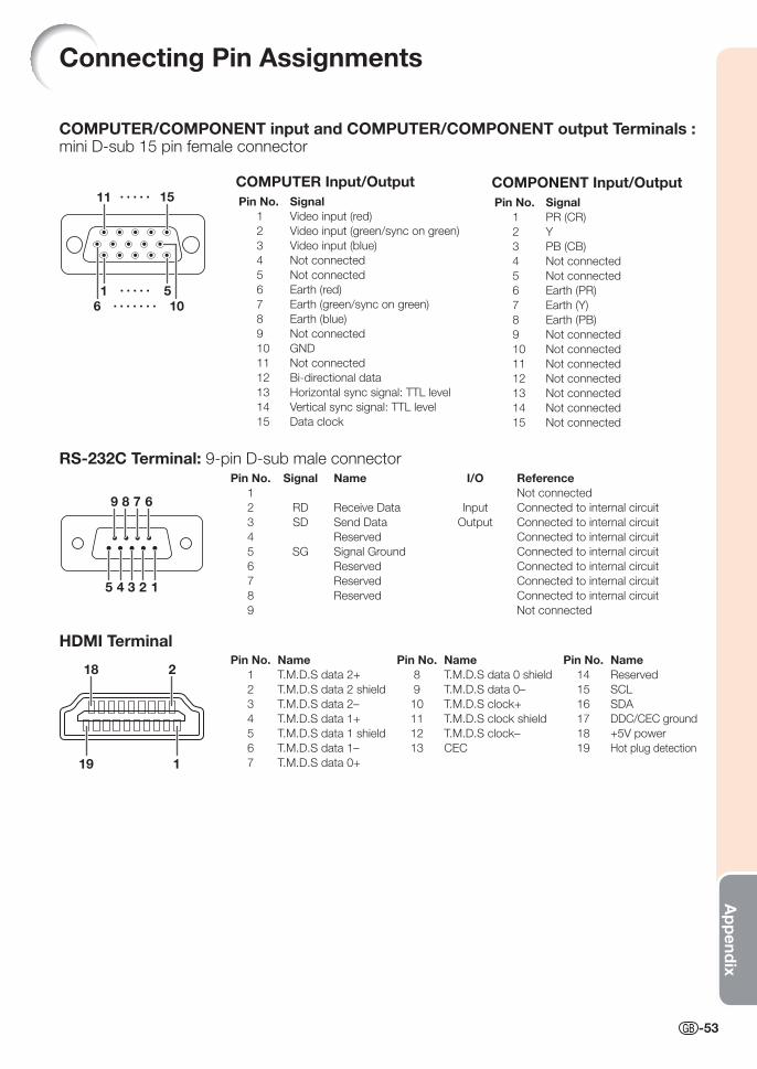
Ap
pend
ix
-53
Connecting Pin Assignments
RS-232C Terminal: 9-pin D-sub male connector Pin No. Signal Name I/O Reference 1 Not connected
2 RD Receive Data Input Connected to internal circuit
3 SD Send Data Output Connected to internal circuit
4 Reserved Connected to internal circuit
5 SG Signal Ground Connected to internal circuit
6 Reserved Connected to internal circuit
7 Reserved Connected to internal circuit
8 Reserved Connected to internal circuit
9 Not connected
COMPUTER/COMPONENT input and COMPUTER/COMPONENT output Terminals : mini D-sub 15 pin female connector
COMPUTER Input/Output Pin No. Signal 1 Video input (red)
2 Video input (green/sync on green)
3 Video input (blue)
4 Not connected
5 Not connected
6 Earth (red)
7 Earth (green/sync on green)
8 Earth (blue)
9 Not connected
10 GND
11 Not connected
12 Bi-directional data
13 Horizontal sync signal: TTL level
14 Vertical sync signal: TTL level
15 Data clock
510
15
1
11
6
4 3 2 1
9 8 7 6
5
18 2
19 1
HDMI Terminal Pin No. Name Pin No. Name Pin No. Name 1 T.M.D.S data 2+ 8 T.M.D.S data 0 shield 14 Reserved
2 T.M.D.S data 2 shield 9 T.M.D.S data 0– 15 SCL
3 T.M.D.S data 2– 10 T.M.D.S clock+ 16 SDA
4 T.M.D.S data 1+ 11 T.M.D.S clock shield 17 DDC/CEC ground
5 T.M.D.S data 1 shield 12 T.M.D.S clock– 18 +5V power
6 T.M.D.S data 1– 13 CEC 19 Hot plug detection
7 T.M.D.S data 0+
COMPONENT Input/Output Pin No. Signal 1 PR (CR)
2 Y
3 PB (CB)
4 Not connected
5 Not connected
6 Earth (PR)
7 Earth (Y)
8 Earth (PB)
9 Not connected
10 Not connected
11 Not connected
12 Not connected
13 Not connected
14 Not connected
15 Not connected
XV-Z15000_E_US.indb 53XV-Z15000_E_US.indb 53 2008/12/25 14:25:482008/12/25 14:25:48
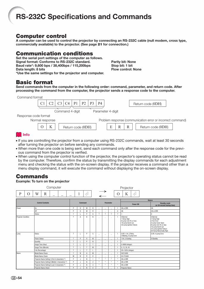
Control Contents Command ParameterReturn
Power ON Standby mode(or 30-second startup time)
Power On P O W R _ _ _ 1 OK or ERR OK
Off P O W R _ _ _ 0 OK OK or ERR
Status T L P S ? ? ? ? 1 0
Projector Condition T A B N _ _ _ 1 0:Normal1:Temp High8:Lamp Life 5% or less16:Lamp Burnt-out32:Lamp Ignition Failure
0:Normal1:Temp High2:Fan Error4:Lamp Cover Open8:Lamp Life 5% or less16:Lamp Burnt-out32:Lamp Ignition Failure64:Temp Abnormally High
Lamp Status T L P S _ _ _ 1 0:Off, 1:On, 2:Retry3:Waiting, 4:Lamp Error
0:Off, 4:Lamp Error
Power Status T P O W _ _ _ 1 1:On, 2:Cooling 0:Standby
Quantity T L P N _ _ _ 1 1
Usage Time (Hour) T L T T _ _ _ 1 0-9999 (Integer)
Usage Time (Minuite) T L T M _ _ _ 1 0, 15, 30, 45
Life (Percentage) T L T L _ _ _ 1 0%-100% (Integer)
Name Model Name Check T N A M _ _ _ 1 XVZ15000
Model Name Check M N R D _ _ _ 1 XV-Z15000
Projector Name Setting1 (First 4 characters) *1 P J N 1 * * * * OK or ERR
Projector Name Setting2 (Middle 4 characters) *1 P J N 2 * * * * OK or ERR
Projector Name Setting3 (Last 4 characters) *1 P J N 3 * * * * OK or ERR
Projector Name Check P J N 0 _ _ _ 1 Projector Name
Computer controlA computer can be used to control the projector by connecting an RS-232C cable (null modem, cross type, commercially available) to the projector. (See page 21 for connection.)
Communication conditions Set the serial port settings of the computer as follows.Signal format: Conforms to RS-232C standard. Parity bit: NoneBaud rate*: 9,600 bps / 38,400bps / 115,200bps Stop bit: 1 bit Data length: 8 bits Flow control: None*Use the same settings for the projector and computer.
Basic format Send commands from the computer in the following order: command, parameter, and return code. After processing the command from the computer, the projector sends a response code to the computer.
Info
• If you are controlling the projector from a computer using RS-232C commands, wait at least 30 seconds after turning the projector on before sending any commands.
• When more than one code is being sent, send each command only after the response code for the previ-ous command from the projector is verifi ed.
• When using the computer control function of the projector, the projector’s operating status cannot be read by the computer. There fore, confi rm the status by transmitting the display commands for each adjustment menu and checking the status with the on-screen display. If the projector receives a command other than a menu display command, it will execute the com mand without displaying the on-screen display.
CommandsExample: To turn on the projector
RS-232C Specifi cations and Commands
Command 4-digit Parameter 4-digit
Command format
C1 C2 C3 C4 P1 P2 P3 P4 Return code (0DH)
Response code format
Normal response Problem response (communication error or incorrect command)
O K Return code (0DH) E R R Return code (0DH)
→←P O W R _ 1_ _ O K
ProjectorComputer
-54
XV-Z15000_E_US.indb 54XV-Z15000_E_US.indb 54 2008/12/25 14:25:492008/12/25 14:25:49
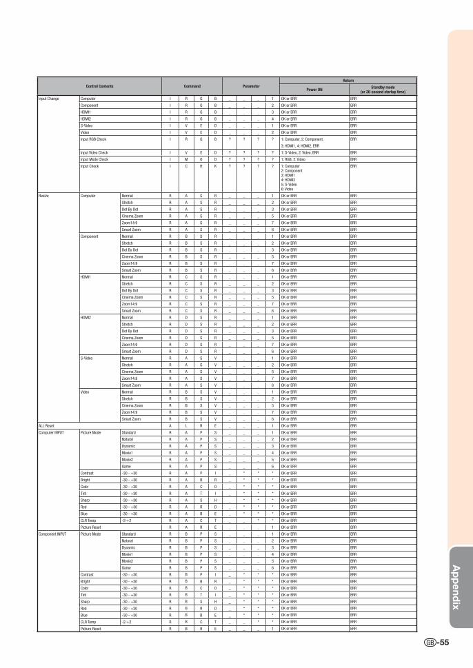
Ap
pend
ix
-55
Control Contents Command ParameterReturn
Power ON Standby mode(or 30-second startup time)
Input Change Computer I R G B _ _ _ 1 OK or ERR ERR
Component I R G B _ _ _ 2 OK or ERR ERR
HDMI1 I R G B _ _ _ 3 OK or ERR ERR
HDMI2 I R G B _ _ _ 4 OK or ERR ERR
S-Video I V E D _ _ _ 1 OK or ERR ERR
Video I V E D _ _ _ 2 OK or ERR ERR
Input RGB Check I R G B ? ? ? ? 1: Computer, 2: Component,
3: HDMI1, 4: HDMI2, ERR
ERR
Input Video Check I V E D ? ? ? ? 1: S-Video, 2: Video, ERR ERR
Input Mode Check I M O D ? ? ? ? 1: RGB, 2: Video ERR
Input Check I C H K ? ? ? ? 1: Computer2: Component3: HDMI14: HDMI25: S-Video6: Video
ERR
Resize Computer Normal R A S R _ _ _ 1 OK or ERR ERR
Stretch R A S R _ _ _ 2 OK or ERR ERR
Dot By Dot R A S R _ _ _ 3 OK or ERR ERR
Cinema Zoom R A S R _ _ _ 5 OK or ERR ERR
Zoom14:9 R A S R _ _ _ 7 OK or ERR ERR
Smart Zoom R A S R _ _ _ 6 OK or ERR ERR
Component Normal R B S R _ _ _ 1 OK or ERR ERR
Stretch R B S R _ _ _ 2 OK or ERR ERR
Dot By Dot R B S R _ _ _ 3 OK or ERR ERR
Cinema Zoom R B S R _ _ _ 5 OK or ERR ERR
Zoom14:9 R B S R _ _ _ 7 OK or ERR ERR
Smart Zoom R B S R _ _ _ 6 OK or ERR ERR
HDMI1 Normal R C S R _ _ _ 1 OK or ERR ERR
Stretch R C S R _ _ _ 2 OK or ERR ERR
Dot By Dot R C S R _ _ _ 3 OK or ERR ERR
Cinema Zoom R C S R _ _ _ 5 OK or ERR ERR
Zoom14:9 R C S R _ _ _ 7 OK or ERR ERR
Smart Zoom R C S R _ _ _ 6 OK or ERR ERR
HDMI2 Normal R D S R _ _ _ 1 OK or ERR ERR
Stretch R D S R _ _ _ 2 OK or ERR ERR
Dot By Dot R D S R _ _ _ 3 OK or ERR ERR
Cinema Zoom R D S R _ _ _ 5 OK or ERR ERR
Zoom14:9 R D S R _ _ _ 7 OK or ERR ERR
Smart Zoom R D S R _ _ _ 6 OK or ERR ERR
S-Video Normal R A S V _ _ _ 1 OK or ERR ERR
Stretch R A S V _ _ _ 2 OK or ERR ERR
Cinema Zoom R A S V _ _ _ 5 OK or ERR ERR
Zoom14:9 R A S V _ _ _ 7 OK or ERR ERR
Smart Zoom R A S V _ _ _ 6 OK or ERR ERR
Video Normal R B S V _ _ _ 1 OK or ERR ERR
Stretch R B S V _ _ _ 2 OK or ERR ERR
Cinema Zoom R B S V _ _ _ 5 OK or ERR ERR
Zoom14:9 R B S V _ _ _ 7 OK or ERR ERR
Smart Zoom R B S V _ _ _ 6 OK or ERR ERR
ALL Reset A L R E _ _ _ 1 OK or ERR ERR
Computer INPUT Picture Mode Standard R A P S _ _ _ 1 OK or ERR ERR
Natural R A P S _ _ _ 2 OK or ERR ERR
Dynamic R A P S _ _ _ 3 OK or ERR ERR
Movie1 R A P S _ _ _ 4 OK or ERR ERR
Movie2 R A P S _ _ _ 5 OK or ERR ERR
Game R A P S _ _ _ 6 OK or ERR ERR
Contrast -30 - +30 R A P I _ * * * OK or ERR ERR
Bright -30 - +30 R A B R _ * * * OK or ERR ERR
Color -30 - +30 R A C O _ * * * OK or ERR ERR
Tint -30 - +30 R A T I _ * * * OK or ERR ERR
Sharp -30 - +30 R A S H _ * * * OK or ERR ERR
Red -30 - +30 R A R D _ * * * OK or ERR ERR
Blue -30 - +30 R A B E _ * * * OK or ERR ERR
CLR Temp -2-+2 R A C T _ _ * * OK or ERR ERR
Picture Reset R A R E _ _ _ 1 OK or ERR ERR
Component INPUT Picture Mode Standard R B P S _ _ _ 1 OK or ERR ERR
Natural R B P S _ _ _ 2 OK or ERR ERR
Dynamic R B P S _ _ _ 3 OK or ERR ERR
Movie1 R B P S _ _ _ 4 OK or ERR ERR
Movie2 R B P S _ _ _ 5 OK or ERR ERR
Game R B P S _ _ _ 6 OK or ERR ERR
Contrast -30 - +30 R B P I _ * * * OK or ERR ERR
Bright -30 - +30 R B B R _ * * * OK or ERR ERR
Color -30 - +30 R B C O _ * * * OK or ERR ERR
Tint -30 - +30 R B T I _ * * * OK or ERR ERR
Sharp -30 - +30 R B S H _ * * * OK or ERR ERR
Red -30 - +30 R B R D _ * * * OK or ERR ERR
Blue -30 - +30 R B B E _ * * * OK or ERR ERR
CLR Temp -2-+2 R B C T _ _ * * OK or ERR ERR
Picture Reset R B R E _ _ _ 1 OK or ERR ERR
XV-Z15000_E_US.indb 55XV-Z15000_E_US.indb 55 2008/12/25 14:25:502008/12/25 14:25:50
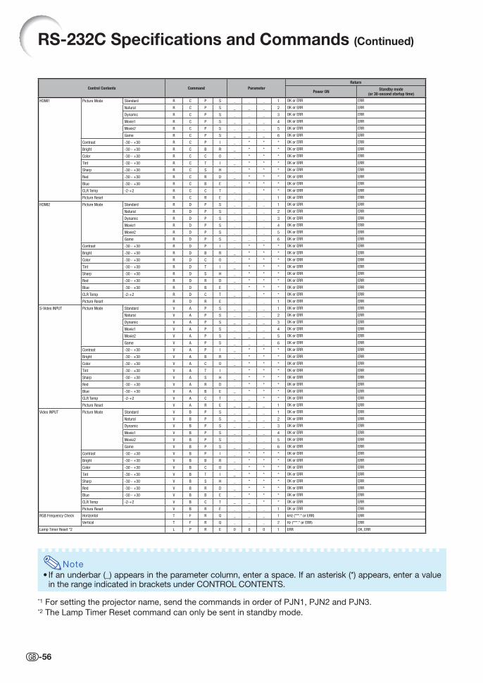
Control Contents Command ParameterReturn
Power ON Standby mode(or 30-second startup time)
HDMI1 Picture Mode Standard R C P S _ _ _ 1 OK or ERR ERR
Natural R C P S _ _ _ 2 OK or ERR ERR
Dynamic R C P S _ _ _ 3 OK or ERR ERR
Movie1 R C P S _ _ _ 4 OK or ERR ERR
Movie2 R C P S _ _ _ 5 OK or ERR ERR
Game R C P S _ _ _ 6 OK or ERR ERR
Contrast -30 - +30 R C P I _ * * * OK or ERR ERR
Bright -30 - +30 R C B R _ * * * OK or ERR ERR
Color -30 - +30 R C C O _ * * * OK or ERR ERR
Tint -30 - +30 R C T I _ * * * OK or ERR ERR
Sharp -30 - +30 R C S H _ * * * OK or ERR ERR
Red -30 - +30 R C R D _ * * * OK or ERR ERR
Blue -30 - +30 R C B E _ * * * OK or ERR ERR
CLR Temp -2-+2 R C C T _ _ * * OK or ERR ERR
Picture Reset R C R E _ _ _ 1 OK or ERR ERR
HDMI2 Picture Mode Standard R D P S _ _ _ 1 OK or ERR ERR
Natural R D P S _ _ _ 2 OK or ERR ERR
Dynamic R D P S _ _ _ 3 OK or ERR ERR
Movie1 R D P S _ _ _ 4 OK or ERR ERR
Movie2 R D P S _ _ _ 5 OK or ERR ERR
Game R D P S _ _ _ 6 OK or ERR ERR
Contrast -30 - +30 R D P I _ * * * OK or ERR ERR
Bright -30 - +30 R D B R _ * * * OK or ERR ERR
Color -30 - +30 R D C O _ * * * OK or ERR ERR
Tint -30 - +30 R D T I _ * * * OK or ERR ERR
Sharp -30 - +30 R D S H _ * * * OK or ERR ERR
Red -30 - +30 R D R D _ * * * OK or ERR ERR
Blue -30 - +30 R D B E _ * * * OK or ERR ERR
CLR Temp -2-+2 R D C T _ _ * * OK or ERR ERR
Picture Reset R D R E _ _ _ 1 OK or ERR ERR
S-Video INPUT Picture Mode Standard V A P S _ _ _ 1 OK or ERR ERR
Natural V A P S _ _ _ 2 OK or ERR ERR
Dynamic V A P S _ _ _ 3 OK or ERR ERR
Movie1 V A P S _ _ _ 4 OK or ERR ERR
Movie2 V A P S _ _ _ 5 OK or ERR ERR
Game V A P S _ _ _ 6 OK or ERR ERR
Contrast -30 - +30 V A P I _ * * * OK or ERR ERR
Bright -30 - +30 V A B R _ * * * OK or ERR ERR
Color -30 - +30 V A C O _ * * * OK or ERR ERR
Tint -30 - +30 V A T I _ * * * OK or ERR ERR
Sharp -30 - +30 V A S H _ * * * OK or ERR ERR
Red -30 - +30 V A R D _ * * * OK or ERR ERR
Blue -30 - +30 V A B E _ * * * OK or ERR ERR
CLR Temp -2-+2 V A C T _ _ * * OK or ERR ERR
Picture Reset V A R E _ _ _ 1 OK or ERR ERR
Video INPUT Picture Mode Standard V B P S _ _ _ 1 OK or ERR ERR
Natural V B P S _ _ _ 2 OK or ERR ERR
Dynamic V B P S _ _ _ 3 OK or ERR ERR
Movie1 V B P S _ _ _ 4 OK or ERR ERR
Movie2 V B P S _ _ _ 5 OK or ERR ERR
Game V B P S _ _ _ 6 OK or ERR ERR
Contrast -30 - +30 V B P I _ * * * OK or ERR ERR
Bright -30 - +30 V B B R _ * * * OK or ERR ERR
Color -30 - +30 V B C O _ * * * OK or ERR ERR
Tint -30 - +30 V B T I _ * * * OK or ERR ERR
Sharp -30 - +30 V B S H _ * * * OK or ERR ERR
Red -30 - +30 V B R D _ * * * OK or ERR ERR
Blue -30 - +30 V B B E _ * * * OK or ERR ERR
CLR Temp -2-+2 V B C T _ _ * * OK or ERR ERR
Picture Reset V B R E _ _ _ 1 OK or ERR ERR
RGB Frequency Check Horizontal T F R Q _ _ _ 1 kHz (***.* or ERR) ERR
Vertical T F R Q _ _ _ 2 Hz (***.* or ERR) ERR
Lamp Timer Reset *2 L P R E 0 0 0 1 ERR OK, ERR
Note
• If an underbar (_) appears in the parameter column, enter a space. If an asterisk (*) appears, enter a value in the range indicated in brackets under CONTROL CONTENTS.
*1 For setting the projector name, send the commands in order of PJN1, PJN2 and PJN3.*2 The Lamp Timer Reset command can only be sent in standby mode.
RS-232C Specifi cations and Commands (Continued)
-56
XV-Z15000_E_US.indb 56XV-Z15000_E_US.indb 56 2008/12/25 14:25:512008/12/25 14:25:51
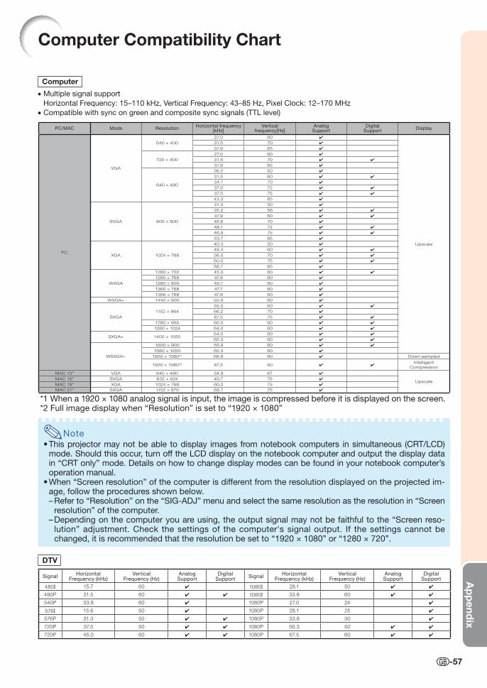
Ap
pend
ix
Computer Compatibility Chart
Computer
• Multiple signal support
Horizontal Frequency: 15–110 kHz, Vertical Frequency: 43–85 Hz, Pixel Clock: 12–170 MHz
• Compatible with sync on green and composite sync signals (TTL level)
Note
• This projector may not be able to display images from notebook computers in simultaneous (CRT/LCD) mode. Should this occur, turn off the LCD display on the notebook computer and output the display data in “CRT only” mode. Details on how to change display modes can be found in your notebook computer’s operation manual.
• When “Screen resolution” of the computer is different from the resolution displayed on the projected im-age, follow the procedures shown below.– Refer to “Resolution” on the “SIG-ADJ” menu and select the same resolution as the resolution in “Screen
resolution” of the computer.– Depending on the computer you are using, the output signal may not be faithful to the “Screen reso-
lution” adjustment. Check the settings of the computer's signal output. If the settings cannot be changed, it is recommended that the resolution be set to “1920 × 1080” or “1280 × 720”.
PC/MAC Mode ResolutionHorizontal frequency
[kHz]Vertical
frequency[Hz]AnalogSupport
DigitalSupport
Display
PC
VGA
640 × 400
27.0 60 ✔
Upscale
31.5 70 ✔
37.9 85 ✔
720 × 400
27.0 60 ✔
31.5 70 ✔ ✔
37.9 85 ✔
640 × 480
26.2 50 ✔
31.5 60 ✔ ✔
34.7 70 ✔
37.9 72 ✔ ✔
37.5 75 ✔ ✔
43.3 85 ✔
SVGA 800 × 600
31.3 50 ✔
35.2 56 ✔ ✔
37.9 60 ✔ ✔
46.6 70 ✔
48.1 72 ✔ ✔
46.9 75 ✔ ✔
53.7 85 ✔
XGA 1024 × 768
40.3 50 ✔
48.4 60 ✔ ✔
56.5 70 ✔ ✔
60.0 75 ✔ ✔
68.7 85 ✔
WXGA
1280 × 720 45.0 60 ✔ ✔
1280 × 768 47.8 60 ✔
1280 × 800 49.7 60 ✔
1360 × 768 47.7 60 ✔
1366 × 768 47.8 60 ✔
WXGA+ 1440 × 900 55.9 60 ✔
SXGA
1152 × 864
55.0 60 ✔ ✔
66.2 70 ✔
67.5 75 ✔ ✔
1280 × 960 60.0 60 ✔ ✔
1280 × 1024 64.0 60 ✔ ✔
SXGA+ 1400 × 105064.0 60 ✔ ✔
65.3 60 ✔ ✔
WSXGA+
1600 × 900 55.9 60 ✔ ✔
1680 × 1050 65.3 60 ✔
1920 × 1080*1 66.8 60 ✔ Down sampled
1920 × 1080*2 67.5 60 ✔ ✔Intelligent
Compression
MAC 13" VGA 640 × 480 34.9 67 ✔
UpscaleMAC 16" SVGA 832 × 624 49.7 75 ✔
MAC 19" XGA 1024 × 768 60.2 75 ✔
MAC 21" SXGA 1152 × 870 68.7 75 ✔
*1 When a 1920 × 1080 analog signal is input, the image is compressed before it is displayed on the screen.*2 Full image display when “Resolution” is set to “1920 × 1080”
DTV
SignalHorizontal
Frequency (kHz)Vertical
Frequency (Hz)AnalogSupport
DigitalSupport
SignalHorizontal
Frequency (kHz)Vertical
Frequency (Hz)AnalogSupport
DigitalSupport
480I 15.7 60 ✔ 1080I 28.1 50 ✔ ✔
480P 31.5 60 ✔ ✔ 1080I 33.8 60 ✔ ✔
540P 33.8 60 ✔ 1080P 27.0 24 ✔
576I 15.6 50 ✔ 1080P 28.1 25 ✔
576P 31.3 50 ✔ ✔ 1080P 33.8 30 ✔
720P 37.5 50 ✔ ✔ 1080P 56.3 50 ✔ ✔
720P 45.0 60 ✔ ✔ 1080P 67.5 60 ✔ ✔
-57
XV-Z15000_E_US.indb 57XV-Z15000_E_US.indb 57 2008/12/25 14:25:522008/12/25 14:25:52
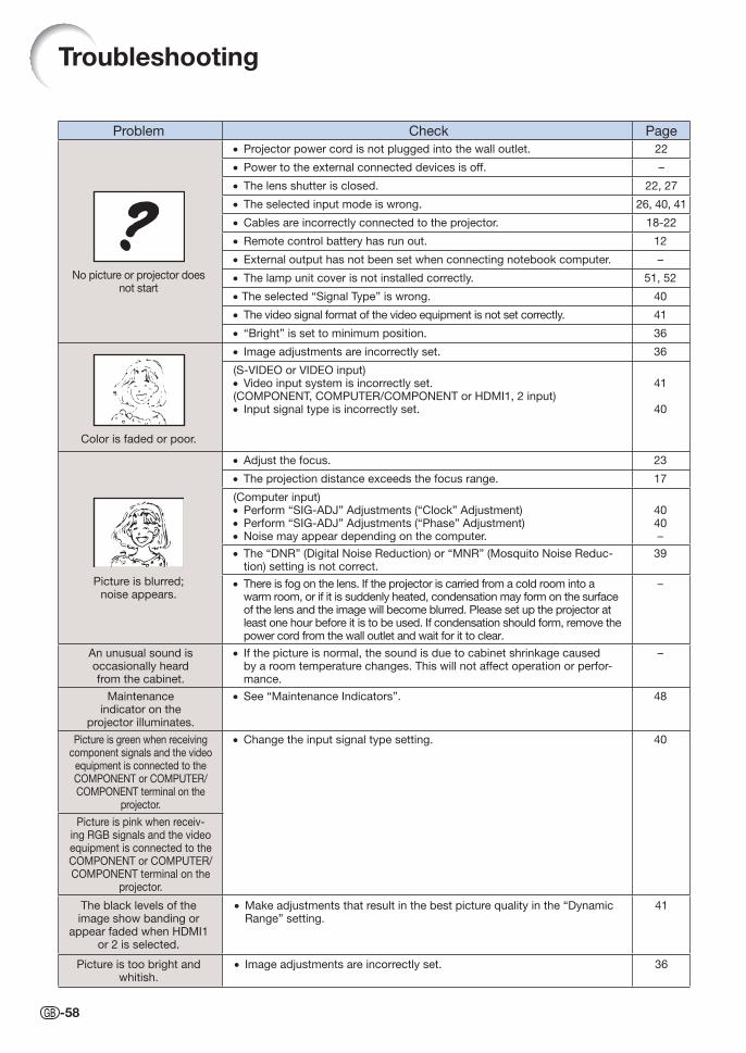
Troubleshooting
Problem Check Page
No picture or projector does not start
• Projector power cord is not plugged into the wall outlet. 22
• Power to the external connected devices is off. –
• The lens shutter is closed. 22, 27
• The selected input mode is wrong. 26, 40, 41
• Cables are incorrectly connected to the projector. 18-22
• Remote control battery has run out. 12
• External output has not been set when connecting notebook computer. –
• The lamp unit cover is not installed correctly. 51, 52
• The selected “Signal Type” is wrong. 40
• The video signal format of the video equipment is not set correctly. 41
• “Bright” is set to minimum position. 36
Color is faded or poor.
• Image adjustments are incorrectly set. 36
(S-VIDEO or VIDEO input)• Video input system is incorrectly set.(COMPONENT, COMPUTER/COMPONENT or HDMI1, 2 input)• Input signal type is incorrectly set.
41
40
Picture is blurred;noise appears.
• Adjust the focus. 23
• The projection distance exceeds the focus range. 17
(Computer input)• Perform “SIG-ADJ” Adjustments (“Clock” Adjustment)• Perform “SIG-ADJ” Adjustments (“Phase” Adjustment)• Noise may appear depending on the computer.
4040–
• The “DNR” (Digital Noise Reduction) or “MNR” (Mosquito Noise Reduc-tion) setting is not correct.
39
• There is fog on the lens. If the projector is carried from a cold room into a warm room, or if it is suddenly heated, condensation may form on the surface of the lens and the image will become blurred. Please set up the projector at least one hour before it is to be used. If condensation should form, remove the power cord from the wall outlet and wait for it to clear.
–
An unusual sound isoccasionally heard from the cabinet.
• If the picture is normal, the sound is due to cabinet shrinkage caused by a room temperature changes. This will not affect operation or perfor-mance.
–
Maintenance indicator on the
projector illuminates.
• See “Maintenance Indicators”. 48
Picture is green when receiving component signals and the video
equipment is connected to the COMPONENT or COMPUTER/COMPONENT terminal on the
projector.
• Change the input signal type setting. 40
Picture is pink when receiv-ing RGB signals and the video equipment is connected to the COMPONENT or COMPUTER/COMPONENT terminal on the
projector.
The black levels of the image show banding or
appear faded when HDMI1 or 2 is selected.
• Make adjustments that result in the best picture quality in the “Dynamic Range” setting.
41
Picture is too bright and whitish.
• Image adjustments are incorrectly set. 36
-58
XV-Z15000_E_US.indb 58XV-Z15000_E_US.indb 58 2008/12/25 14:25:532008/12/25 14:25:53
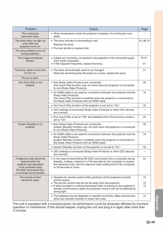
Ap
pend
ix
-59
Problem Check Page
The cooling fanbecomes noisy.
• When temperature inside the projector increases, the cooling fan runs faster.
–
The lamp does not light up even after the
projector turns on.
• The lamp indicator is illuminating in red.
Replace the lamp.
• The lens shutter is opened fully.
22, 48, 51
The lamp suddenly turns off during projection.
The image sometimes fl ickers.
• Cables are incorrectly connected to the projector or the connected equip-ment works improperly.
• If this happens frequently, replace the lamp.
18-21
51
The lamp needs much time to turn on.
• The lamp will eventually need to be changed.
While the remaining lamp life draws to a close, replace the lamp.
51
Picture is dark.
One Touch Play is not enabled.
• Non-Sharp Video Products are connected. One Touch Play function may not work when the projector is connected
to non-Sharp Video Products.
45
• An HDMI cable is not used for connection between the projector and the Sharp Video Products.
One Touch Play function is enabled when the projector is connected to the Sharp Video Products with an HDMI cable.
19
• One Touch Play function of the projector is not set to “On”. 45
• CEC settings of connected Sharp Video Products or other CEC devices are incorrect.
–
• One Touch Play is set to “Off” and disabled when the Economy mode is set to “On”.
45
System Standby is not enabled.
• Non-Sharp Video Products are connected. System Standby function may not work when the projector is connected
to non-Sharp Video Products.
45
• An HDMI cable is not used for connection between the projector and the Sharp Video Products.
System Standby function is enabled when the projector is connected to the Sharp Video Products with an HDMI cable.
19
• System Standby function of the projector is not set to “On”. 45
• CEC settings of connected Sharp Video Products or other CEC devices are incorrect.
–
A response code cannot be received when the
projector was attempted to be controlled using
RS-232C commands from a computer during standby.
• In the case of transmitting RS-232C commands from a computer during standby, it takes a maximum of 30 seconds for the computer to receive the response code. Set the response code waiting time of the computer to 30 seconds or more.
54
The remote controlcannot be used.
• Operate the remote control while pointing it at the projector’s remote control sensor.
• The remote control may be too far away from the projector.• If direct sunlight or a strong fl uorescent light is shining on the projector’s
remote control sensor, place the projector where it will not be affected by strong light.
12
1212
• The batteries may be depleted or inserted incorrectly. Make sure the bat-teries are inserted correctly or insert new ones.
12
This unit is equipped with a microprocessor. Its performance could be adversely affected by incorrect operation or interference. If this should happen, unplug the unit and plug it in again after more than 5 minutes.
XVZ15000_E_US_09.indd 59XVZ15000_E_US_09.indd 59 2009/01/14 15:43:052009/01/14 15:43:05

-60
U.S.A. Sharp Electronics Corporation 1-888-GO-SHARP (1-888-467-4277)
[email protected] http://www.sharpusa.com
Canada Sharp Electronics of Canada Ltd. (905) 568-7140
http://www.sharp.ca
Mexico Sharp Electronics Corporation Mexico Branch
(525) 716-9000 http://www.sharp.com.mx
Latin America Sharp Electronics Corp. Latin American Group
(305) 264-2277 [email protected] http://www.siempresharp.com
Germany Sharp Electronics (Europe) GMBH 01805-234675 http://www.sharp.de
U.K. Sharp Electronics (U.K.) Ltd. 08705 274277 http://www.sharp.co.uk/customersupport
Italy Sharp Electronics (Italy) S.P.A. (39) 02-89595-1 http://www.sharp.it
France Sharp Electronics France 01 49 90 35 40 [email protected] http://www.sharp.fr
Spain Sharp Electronica Espana, S.A. 93 5819700 [email protected] http://www.sharp.es
Switzerland Sharp Electronics (Schweiz) AG 0041 1 846 63 11 [email protected] http://www.sharp.ch
Sweden Sharp Electronics ( Nordic ) AB (46) 8 6343600 [email protected] http://www.sharp.se
Austria Sharp Electronics (Europe) GMBH Branch Offi ce Austria 0043 1 727 19 123 [email protected] http://www.sharp.at
Benelux SHARP Electronics Benelux BV 0900-SHARPCE (0900-7427723)
Nederland 9900-0159 Belgium http://www.sharp.nl http://www.sharp.be http://www.sharp.lu
Australia Sharp Corporation of Australia Pty. Ltd.
1300-135-022 http://www.sharp.net.au
New Zealand Sharp Corporation of New Zealand Phone: (09) 573-0111 Fax: (09) 573-0112 http://www.sharp.net.nz
Singapore Sharp-Roxy Sales (S) Pte. Ltd. 65-226-6556 [email protected] http://www.sharp.com.sg
Hong Kong Sharp-Roxy (HK) Ltd. (852) 2410-2623 [email protected] http://www.sharp.com.hk
Taiwan Sharp Corporation (Taiwan) 0800-025111 http://www.sharp-scot.com.tw
Malaysia Sharp-Roxy Sales & Service Co. (60) 3-5125678
U.A.E. Sharp Middle East Fze 971-4-81-5311 [email protected]
Thailand Sharp Thebnakorn Co. Ltd. 02-236-0170 [email protected] http://www.sharp-th.com
Korea Sharp Electronics Incorporated of Korea
(82) 2-3660-2002 [email protected] http://www.sharpkorea.co.kr
India Sharp Business Systems (India) Limited
(91) 11- 6431313 [email protected]
For SHARP Assistance
If you encounter any problems during setup or operation of this projector, fi rst refer to the “Troubleshooting” section on pages 58 and 59. If this operation manual does not answer your question, please contact the SHARP Service departments listed below.
XV-Z15000_E_US.indb 60XV-Z15000_E_US.indb 60 2008/12/25 14:25:532008/12/25 14:25:53
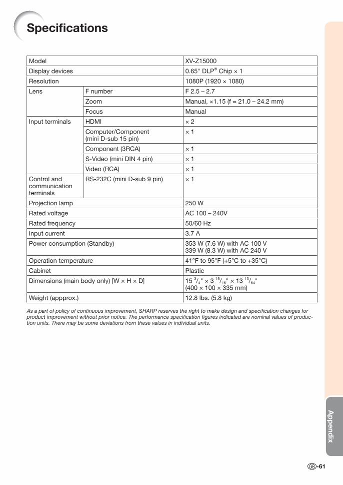
Ap
pend
ix
-61
Specifi cations
Model XV-Z15000
Display devices 0.65" DLP® Chip × 1
Resolution 1080P (1920 × 1080)
Lens F number F 2.5 – 2.7
Zoom Manual, ×1.15 (f = 21.0 – 24.2 mm)
Focus Manual
Input terminals HDMI × 2
Computer/Component (mini D-sub 15 pin)
× 1
Component (3RCA) × 1
S-Video (mini DIN 4 pin) × 1
Video (RCA) × 1
Control and communication terminals
RS-232C (mini D-sub 9 pin) × 1
Projection lamp 250 W
Rated voltage AC 100 – 240V
Rated frequency 50/60 Hz
Input current 3.7 A
Power consumption (Standby) 353 W (7.6 W) with AC 100 V339 W (8.3 W) with AC 240 V
Operation temperature 41°F to 95°F (+5°C to +35°C)
Cabinet Plastic
Dimensions (main body only) [W × H × D] 15 3/4" × 3
15/16" × 13
13/64"
(400 × 100 × 335 mm)
Weight (appprox.) 12.8 lbs. (5.8 kg)
As a part of policy of continuous improvement, SHARP reserves the right to make design and specifi cation changes for product improvement without prior notice. The performance specifi cation fi gures indicated are nominal values of produc-tion units. There may be some deviations from these values in individual units.
XV-Z15000_E_US.indb 61XV-Z15000_E_US.indb 61 2008/12/25 14:25:542008/12/25 14:25:54
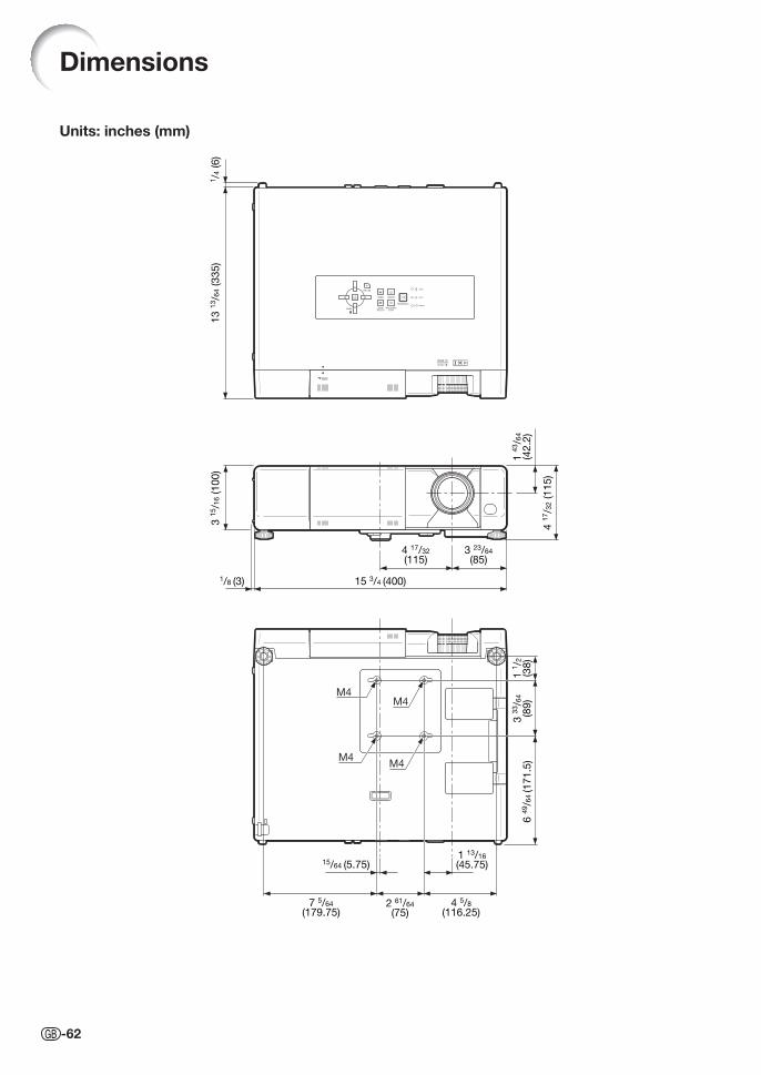
-62
Dimensions
Units: inches (mm)
M4M4
M4M4
1/4
(6
)1
3 1
3/6
4 (3
35
)3
15/1
6 (1
00
)
1 4
3/6
4
(42
.2)
4 1
7/3
2 (1
15
)3 23/64
(85)4 17/32
(115)
15 3/4 (400)1/8 (3)
1 1
/2(3
8)
3 3
3/6
4
(89
)6
49/6
4 (1
71
.5)
15/64 (5.75)1 13/16
(45.75)
4 5/8
(116.25)2 61/64
(75)7 5/64
(179.75)
XV-Z15000_E_US.indb 62XV-Z15000_E_US.indb 62 2008/12/25 14:25:542008/12/25 14:25:54
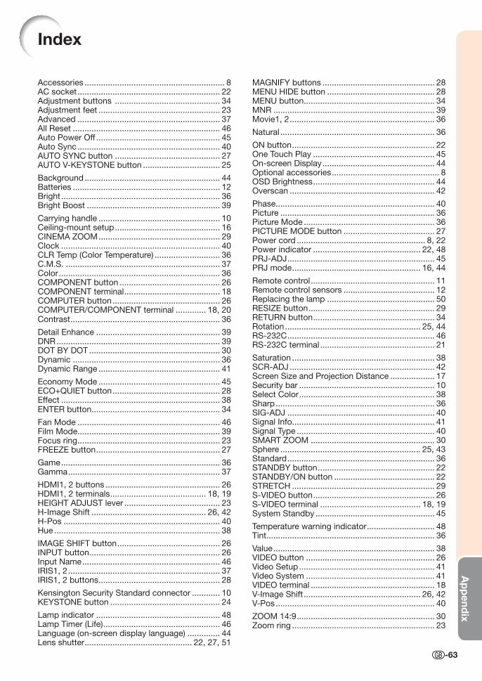
Ap
pend
ix
-63
Accessories ............................................................ 8AC socket ............................................................. 22Adjustment buttons ............................................. 34Adjustment feet .................................................... 23Advanced ............................................................. 37All Reset ............................................................... 46Auto Power Off ..................................................... 45Auto Sync ............................................................. 40AUTO SYNC button ............................................. 27AUTO V-KEYSTONE button ................................. 25
Background .......................................................... 44Batteries ............................................................... 12Bright .................................................................... 36Bright Boost ......................................................... 39
Carrying handle .................................................... 10Ceiling-mount setup ............................................. 16CINEMA ZOOM .................................................... 29Clock .................................................................... 40CLR Temp (Color Temperature) ............................ 36C.M.S. .................................................................. 37Color ..................................................................... 36COMPONENT button ........................................... 26COMPONENT terminal ......................................... 18COMPUTER button .............................................. 26COMPUTER/COMPONENT terminal ............. 18, 20Contrast ................................................................ 36
Detail Enhance ..................................................... 39DNR ...................................................................... 39DOT BY DOT ........................................................ 30Dynamic ............................................................... 36Dynamic Range .................................................... 41
Economy Mode .................................................... 45ECO+QUIET button .............................................. 28Effect .................................................................... 38ENTER button ....................................................... 34
Fan Mode ............................................................. 46Film Mode ............................................................. 39Focus ring ............................................................. 23FREEZE button ..................................................... 27
Game .................................................................... 36Gamma ................................................................. 37
HDMI1, 2 buttons ................................................. 26HDMI1, 2 terminals ......................................... 18, 19HEIGHT ADJUST lever ......................................... 23H-Image Shift ................................................. 26, 42H-Pos ................................................................... 40Hue ....................................................................... 38
IMAGE SHIFT button ............................................ 26INPUT button ........................................................ 26Input Name ........................................................... 46IRIS1, 2 ................................................................. 37IRIS1, 2 buttons .................................................... 28
Kensington Security Standard connector ............ 10KEYSTONE button ............................................... 24
Lamp indicator ..................................................... 48Lamp Timer (Life) .................................................. 46Language (on-screen display language) .............. 44Lens shutter .............................................. 22, 27, 51
Index
MAGNIFY buttons ................................................ 28MENU HIDE button .............................................. 28MENU button ........................................................ 34MNR ..................................................................... 39Movie1, 2 .............................................................. 36
Natural .................................................................. 36
ON button ............................................................. 22One Touch Play .................................................... 45On-screen Display ................................................ 44Optional accessories .............................................. 8OSD Brightness .................................................... 44Overscan .............................................................. 42
Phase .................................................................... 40Picture .................................................................. 36Picture Mode ........................................................ 36PICTURE MODE button ....................................... 27Power cord ....................................................... 8, 22Power indicator .............................................. 22, 48PRJ-ADJ ............................................................... 45PRJ mode ....................................................... 16, 44
Remote control ..................................................... 11Remote control sensors ....................................... 12Replacing the lamp .............................................. 50RESIZE button ...................................................... 29RETURN button .................................................... 34Rotation .......................................................... 25, 44RS-232C ............................................................... 46RS-232C terminal ................................................. 21
Saturation ............................................................. 38SCR-ADJ .............................................................. 42Screen Size and Projection Distance ................... 17Security bar .......................................................... 10Select Color .......................................................... 38Sharp .................................................................... 36SIG-ADJ ............................................................... 40Signal Info ............................................................. 41Signal Type ........................................................... 40SMART ZOOM ..................................................... 30Sphere ............................................................ 25, 43Standard ............................................................... 36STANDBY button .................................................. 22STANDBY/ON button ........................................... 22STRETCH ............................................................. 29S-VIDEO button .................................................... 26S-VIDEO terminal ........................................... 18, 19System Standby ................................................... 45
Temperature warning indicator ............................. 48Tint ........................................................................ 36
Value ..................................................................... 38VIDEO button ....................................................... 26Video Setup .......................................................... 41Video System ....................................................... 41VIDEO terminal ..................................................... 18V-Image Shift .................................................. 26, 42V-Pos .................................................................... 40
ZOOM 14:9 ........................................................... 30Zoom ring ............................................................. 23
XV-Z15000_E_US.indb 63XV-Z15000_E_US.indb 63 2008/12/25 14:25:542008/12/25 14:25:54

XV-Z
15000
XV-Z15000PROJECTORPROJECTEURPROYECTORPROJETOR
Printed in ChinaImprimé en ChineImpreso en ChinaImpresso na ChinaTINS-E012WJZZ09P01-CH-NM
EN
GLIS
HFR
AN
ÇA
ISE
SPA
ÑO
LP
OR
TU
GU
ÊS
OPERATION MANUALMODE D’EMPLOIMANUAL DE MANEJOMANUAL DE OPERAÇÃO
SHARP CORPORATION
XVZ15000_E_US_Hyo1-4.indd 1XVZ15000_E_US_Hyo1-4.indd 1 2008/12/25 15:07:122008/12/25 15:07:12
Recommended