COPYRIGHT
WSA 109:2021
Flanged Gaskets and O-rings
Third Edition
Version 3.1
WSA 109:2021
WSA 109:2021 Version 3.1 2
COPYRIGHT
ACKNOWLEDGMENTS
WSAA acknowledges the significant technical input of Peter Pittard (WSAA Consultant)
and Jason Hall (Reece Australia Pty Ltd) for their contribution to the revision of this Water
Industry Standard.
Other organisations that contributed includes Plastics Industry Pipe Association of
Australia(PIPA), Steel Mains Pty Ltd, Hultec Asia Pacific Pty Ltd, Clover Pipelines Pty Ltd,
Daemco Australia Pty Ltd, Industrial Gaskets and Sealing Devices Pty Ltd.
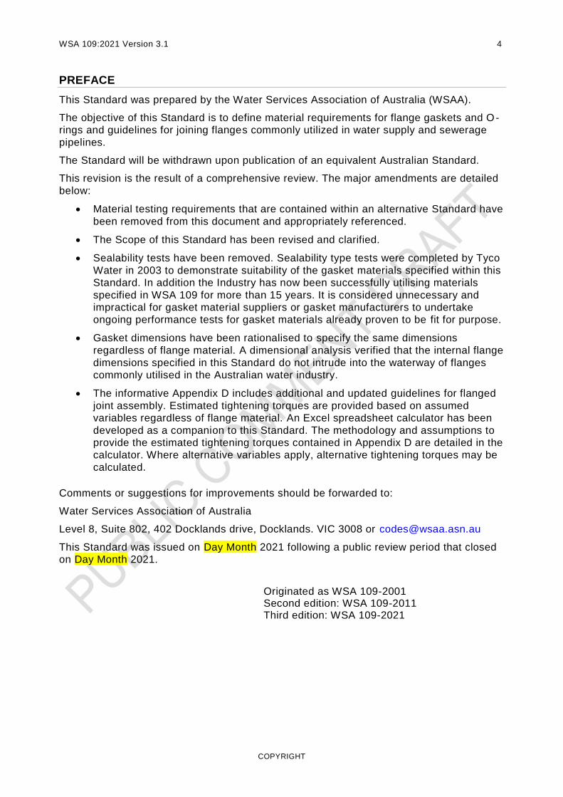
The following individuals peer reviewed this revision and provided comments and
suggestions.
?????
DISCLAIMER
WSAA Manuals are published by Water Services Association of Australia Limited on the
understanding that:
Water Services Association of Australia Limited and individual contributors are not
responsible for the results of any action taken on the basis of information provided
within the Water Industry Standard for Flanged Gaskets and O-rings, nor any errors
or omissions.
Water Services Association of Australia Limited and individual contributors disclaim
all and any liability to any person in respect of anything, and the consequences of
anything, done or omitted to be done by a person in reliance upon the whole or any
part of the Water Industry Standard for Flanged Gaskets and O-rings.

COPYRIGHT
PUBLICATION DETAILS
Published by:
Water Services Association of Australia Limited
Level 8 Suite 8.02
401 Docklands Drive
Docklands VIC 3008
ISBN details to be inserted
COPYRIGHT
Water Services Association of Australia will permit up to 20 percent of th is Manual to be
copied for use exclusively in house by purchasers of this Manual, for use in contract
documentation and for training purposes without payment of a royalty or giving advice to
Water Services Association of Australia Limited.
© Copyright 2021 by WATER SERVICES ASSOCIATION of Australia Limited All rights
reserved.
WSA 109:2021 Version 3.1 4
COPYRIGHT
PREFACE
This Standard was prepared by the Water Services Association of Australia (WSAA).
The objective of this Standard is to define material requirements for flange gaskets and O-
rings and guidelines for joining flanges commonly utilized in water supply and sewerage
pipelines.
The Standard will be withdrawn upon publication of an equivalent Australian Standard.
This revision is the result of a comprehensive review. The major amendments are detailed
below:
Material testing requirements that are contained within an alternative Standard have
been removed from this document and appropriately referenced.
The Scope of this Standard has been revised and clarified.
Sealability tests have been removed. Sealability type tests were completed by Tyco
Water in 2003 to demonstrate suitability of the gasket materials specified within this
Standard. In addition the Industry has now been successfully utilising materials
specified in WSA 109 for more than 15 years. It is considered unnecessary and
impractical for gasket material suppliers or gasket manufacturers to undertake
ongoing performance tests for gasket materials already proven to be fit for purpose.
Gasket dimensions have been rationalised to specify the same dimensions
regardless of flange material. A dimensional analysis verified that the internal flange
dimensions specified in this Standard do not intrude into the waterway of flanges
commonly utilised in the Australian water industry.
The informative Appendix D includes additional and updated guidelines for flanged
joint assembly. Estimated tightening torques are provided based on assumed
variables regardless of flange material. An Excel spreadsheet calculator has been
developed as a companion to this Standard. The methodology and assumptions to
provide the estimated tightening torques contained in Appendix D are detailed in the
calculator. Where alternative variables apply, alternative tightening torques may be
calculated.
Comments or suggestions for improvements should be forwarded to:
Water Services Association of Australia
Level 8, Suite 802, 402 Docklands drive, Docklands. VIC 3008 or [email protected]
This Standard was issued on Day Month 2021 following a public review period that closed
on Day Month 2021.
Originated as WSA 109-2001 Second edition: WSA 109-2011 Third edition: WSA 109-2021

COPYRIGHT
CONTENTS
ACKNOWLEDGMENTS 2
PREFACE 4
1 SCOPE AND GENERAL 6 1.1 SCOPE 6 1.2 REFERENCED DOCUMENTS 6 1.3 DEFINITIONS 7 1.4 ALLOWABLE PRESSURES 7
2 MATERIALS 7 2.1 GENERAL 7 2.2 CONTAMINATION OF WATER 8 2.3 MATERIAL REQUIREMENTS 8 2.4 MATERIAL PROPERTIES 8
2.4.1 Elastomeric flange gaskets and O-rings 8 2.4.2 Compressed fibre gaskets 8
3 MANUFACTURING REQUIREMENTS 8 3.1 FORM 8 3.2 DIMENSIONS 9 3.3 IMPERFECTIONS AND DEFECTS 9 3.4 O-RING SPLICE JOINT 9 3.5 MARKING 9 3.6 STORAGE 9
APPENDIX A MEANS FOR DEMONSTRATING CONFORMITY WITH THIS STANDARD
10
APPENDIX B PURCHASING GUIDELINES 12 B1 GENERAL 12 B2 INFORMATION TO BE SUPPLIED BY THE PURCHASER 12 B3 CERTIFICATES 12
B3.1 Certificate of compliance 12 B3.2 Test certificate 12
B4 INFORMATION TO BE SUPPLIED BY THE MANUFACTURER 13
APPENDIX C GASKET DIMENSIONS 14 C1 DIMENSIONS 14 C2 TOLERANCES 14
APPENDIX D FLANGED JOINT ASSEMBLY 17 D1 SCOPE 17 D2 DISCLAIMER 17 D3 FLANGED JOINTS 17 D4 GASKETS 18 D5 FASTENERS 18 D6 ASSEMBLY OF FLANGED JOINTS 19 D7 PRECAUTIONS 19 D8 PROCEDURE 20
D8.1 JOINTING INSTRUCTIONS FOR FLANGED JOINTS 20 D8.2 ESTIMATED TIGHTENING TORQUE VALUES 20

COPYRIGHT
1 SCOPE AND GENERAL
1.1 SCOPE
This Standard specifies requirements for solid elastomeric and compressed non-asbestos
fibre gaskets and elastomeric O-rings suitable for jointing metallic flanges that comply with
AS/NZS 4087.
Gasket materials may also be suitable for flanges that comply with AS/NZS 4331.1,
AS/NZS 4331.2, AS/NZS 4331.3, AS 2129 and other metallic flange standards, however
dimensions will be different and appropriate assembly torques will need to be assessed.
Fabric reinforced or composite elastomeric gaskets are not included.
Gaskets and O-rings complying with the material requirements of this Standard may be
used for PN 14, 16, 21 and 35 flanged joints complying with AS/NZS 4087 for all metallic
pipeline materials, including iron, steel, copper and copper alloys for drinking and non-
drinking water supply, drainage and sewerage for operating temperatures up to 50°C (AS
681-1 Type WA). Material specifications for other operating temperatures are not included.
AS/NZS 4087 Appendix C provides recommendations for the selection of appropriate
gasket materials (including thickness) and fasteners for various metallic flange materials,
pressure classifications and flange face types.
Jointing guidelines for polyethylene flanges may be sourced from POP 007 published by
the Plastics Industry Pipe Association of Australia (PIPA) or AS/NZS 4129:2020. A flange
bolt torque calculator is also available from Iplex Australia at the following link:
https://www.pocketengineer.com.au/Fbtc/step1wizard
Means for demonstrating compliance with this Standard are given in Appendix A.
Purchasing guidelines are given in Appendix B.
Dimensions for gaskets and O-rings are given in Appendix C.
Guidelines for the assembly of flanged joints are given in Appendix D.
1.2 REFERENCED DOCUMENTS
AS
681-1 Elastomeric seals–Material requirements for pipe joints used in water
and drainage applications Part 1: Vulcanized rubber
1646 Elastomeric seals for waterworks purposes
2129 Flanges for pipes, valves and fittings
AS/NZS
4020 Testing of products for use in contact with drinking water
4087 Metallic flanges for waterworks purposes
4129 Fittings for (PE) polyethylene pipes for pressure applications
4331.1 Metallic flanges - Steel flanges
4331.2 Metallic flanges - Cast iron flanges
4331.3 Metallic flanges - Copper alloy and composite flanges

COPYRIGHT
ASTM
F 36 Standard Test Method for Compressibility and Recovery of Gasket
Materials
F 37 Standard Test Method for Sealability of Gasket Materials
F 38 Standard Test Methods for Creep Relaxation of a Gasket Material
F 104 Classification System for Nonmetallic Gasket Materials
F 146 Standard Test Methods for Fluid Resistance of Gasket Materials
ISO/IEC
17025 General requirements for competence of testing and calibration
laboratories
ISO
37 Rubber, vulcanized or thermoplastic—Determination of tensile stress-
strain properties
2230 Vulcanized rubber—Guide to storage
9691 Rubber—Recommendation for the workmanship of pipe joint rings—
Description and classification of imperfections.
PIPA
POP 007 Metal backing flanges for use with polyethylene (PE) pipe flange
adaptors
1.3 DEFINITIONS
For the purpose of this Standard the definitions given in AS/NZS 2280 and AS/NZS 4087
apply.
1.4 ALLOWABLE PRESSURES
Allowable pressures for flange gaskets and O-rings shall be as given in Table 1.1.
TABLE 1.1
ALLOWABLE PRESSURES
Component PN AOP
kPa
MAOP
kPa
ASTP
kPa
Elastomeric gasket or O-ring 16 1600 1920 2000
Compressed fibre gasket or O-ring 35 3500 4200 4375
2 MATERIALS
2.1 GENERAL
The materials shall be free of any substances that may have a deleterious effect on the
fluid being conveyed or on the life of the gasket, O-ring, flange or fasteners.

COPYRIGHT
2.2 CONTAMINATION OF WATER
Flange gaskets and O-rings shall comply with AS/NZS 4020. A scaling factor of 0.01 shall
be applied.
2.3 MATERIAL REQUIREMENTS
Gaskets and O-rings shall be manufactured from materials complying with the
requirements of Table 2.1.
TABLE 2.1
MATERIAL REQUIREMENTS
Component Material Standard Specification
Elastomeric gasket EPDM, NBR, SBR AS 1646 and AS 681.1 60 or 70 IRHD
O-ring EPDM, NBR, SBR AS 1646 and AS 681.1 40 IRHD
Compressed fibre gasket Non asbestos fibre ASTM F104 Type 7 Class 1
2.4 MATERIAL PROPERTIES
2.4.1 Elastomeric flange gaskets and O-rings
The material properties for the elastomeric gaskets and O-rings shall comply with AS 1646
and AS 681.1 Type WA for the applicable material specifications given in Table 2.1.
A sealing stress of no less than 2 MPa and a crushing stress greater than 16 MPa is
nominated for the elastomeric flange gasket materials specified in this Standard.
2.4.2 Compressed fibre gaskets
The material properties for the ASTM F104 Type 7 Class 1 material shall comply with
Table 2.2.
TABLE 2.2
MATERIAL PROPERTIES FOR COMPRESSED FIBRE
3 MANUFACTURING REQUIREMENTS
3.1 FORM
Gaskets shall be solid without fabric reinforcement or other composite materials. The
surfaces may be flat or profiled to the manufacturer’s design requirements.
Material Property Unit Value Test Method
Tensile Strength MPa > 3 ASTM F152
Creep relaxation 22 h at 100˚C % < 25 ASTM F 38 Method B
5 h at 100˚C % < 5 ASTM F 146
Recovery % > 40 ASTM F 36 Procedure J
Compressibility % > 15 ASTM F 36 Procedure J
Sealing stress MPa > 15 Manufacturer
Crushing stress MPA > 100 Manufacturer

COPYRIGHT
3.2 DIMENSIONS
Dimensions for flange gaskets for use with AS/NZS 4087 flanges are given in Appendix C.
O-rings shall comply with the dimensional requirements specified in AS/NZS 4087 or where
otherwise specified for alternative O-ring groove dimensions.
3.3 IMPERFECTIONS AND DEFECTS
Elastomeric gaskets and O-rings shall be free of defects and irregularities which could
affect their function. Classification of imperfections shall be in accordance with ISO 9691.
Limits on imperfections and defects for compressed fibre gaskets shall be in accordance
with the manufacturer’s requirements.
3.4 O-RING SPLICE JOINT
Each O-ring splice joint shall show no visible sign of separation when tested in accordance
with AS 1646 or AS 681-1.
3.5 MARKING
Each gasket shall be marked clearly and durably in accordance with the following such that
identification is visible at the time of installation and the sealing capability is not impaired.
A stick-on label may be utilised where practicable.
(a) Manufacturer’s identification.
(b) Nominal size.
(c) Flange compatibility and pressure classification
(d) The number of this Standard with the type of application and hardness class as a
suffix, e.g. WSA 109 WA/70.
(e) Year of manufacture.
(f) The abbreviation for the elastomer material, e.g. EPDM.
Example
Name/DN100/ASNZS4087PN16/WSA109/WA/70/2020/EPDM
NOTE: Manufacturers making a statement of compliance with this Water Industry Standard on a product,
packaging or promotional material related to that product are advised to ensure that such compliance is
capable of being verified.
3.6 STORAGE
Gaskets and O-rings shall be stored under the following conditions:
(a) at temperatures less than 25 oC
(b) protected from light or other UV sources
(c) not in a room with any equipment capable of generating ozone e.g. mercury vapour
lamps, high voltage electrical equipment, electric motors or other equipment that
could cause electrical discharges
(d) in a relaxed condition free from tension, compression or other deformation.
NOTE: For additional information on the storage of elastomeric gaskets and O-rings see ISO 2230.
COPYRIGHT
APPENDIX A MEANS FOR DEMONSTRATING CONFORMITY WITH THIS STANDARD
(Normative)
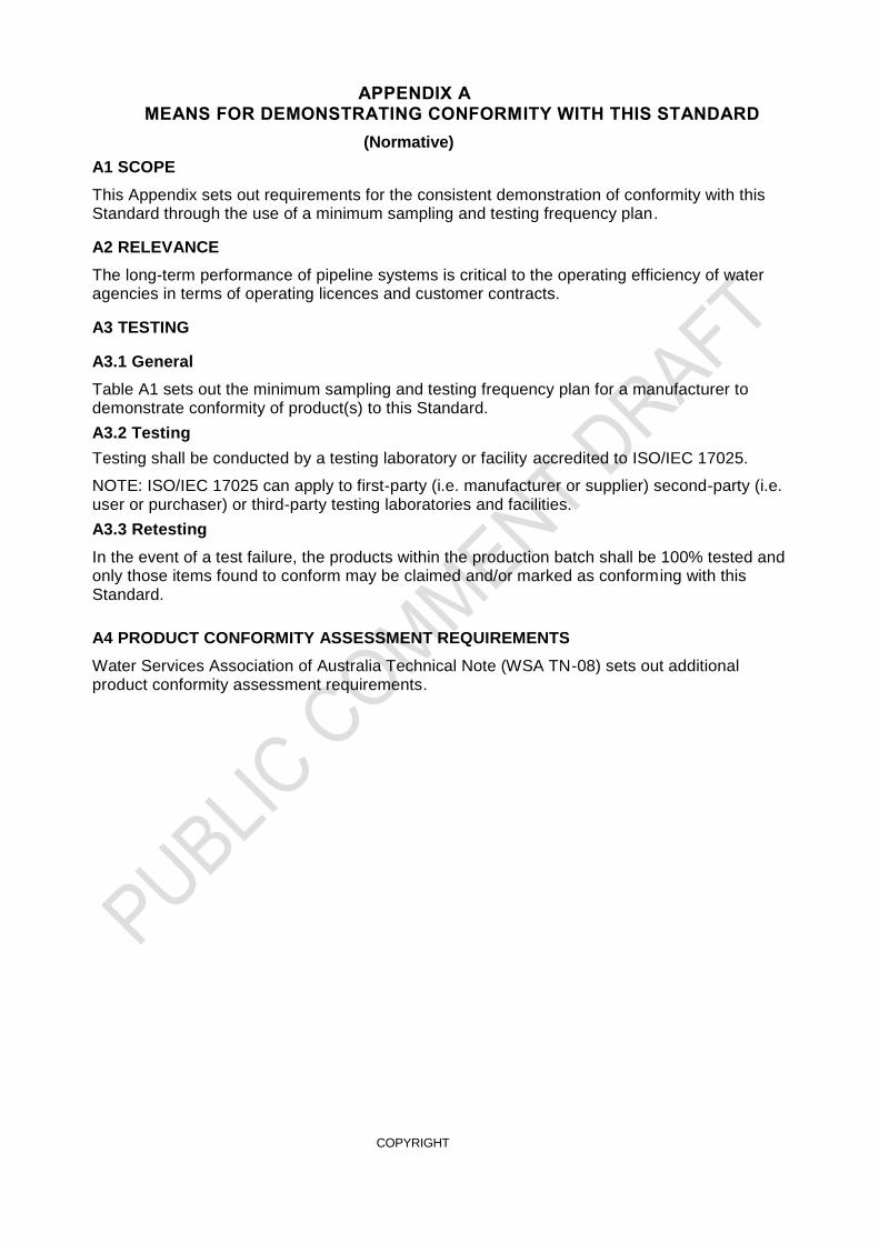
A1 SCOPE
This Appendix sets out requirements for the consistent demonstration of conformity with this Standard through the use of a minimum sampling and testing frequency plan.
A2 RELEVANCE
The long-term performance of pipeline systems is critical to the operating efficiency of water agencies in terms of operating licences and customer contracts.
A3 TESTING
A3.1 General
Table A1 sets out the minimum sampling and testing frequency plan for a manufacturer to demonstrate conformity of product(s) to this Standard.
A3.2 Testing
Testing shall be conducted by a testing laboratory or facility accredited to ISO/IEC 17025.
NOTE: ISO/IEC 17025 can apply to first-party (i.e. manufacturer or supplier) second-party (i.e. user or purchaser) or third-party testing laboratories and facilities.
A3.3 Retesting
In the event of a test failure, the products within the production batch shall be 100% tested and only those items found to conform may be claimed and/or marked as conforming with this Standard.
A4 PRODUCT CONFORMITY ASSESSMENT REQUIREMENTS
Water Services Association of Australia Technical Note (WSA TN-08) sets out additional product conformity assessment requirements.

COPYRIGHT
TABLE A1
MINIMUM SAMPLING AND TESTING FREQUENCY PLAN
Characteristic Clause Requirement Test method Frequency
Type Tests
Material 2.2 Contamination of water AS/NZS 4020 At any change in
material or every 5
years
Material Properties -
elastomeric gaskets
and O-rings
2.4.1 Hardness
AS 1646 and AS 681-1
Annually (except
tests with a duration
of more than 28
days are repeated
each 5 years) or
where there is a
change in
formulation or
manufacturing
technique
Tensile strength and
elongation at break
Compression set in air
Accelerated aging in air
Stress relaxation in
compression
Volume change in water
Material properties –
compressed fibre
gaskets
2.4.2 Tensile strength ISO 37 Annually or where
there is a change in
formulation or
manufacturing
technique
Creep relaxation in
compression ASTM F38 Method B
Thickness change in water ASTM F146
Recovery ASTM F36 Procedure J
Compressibility ASTM F36 Procedure J
Minimum sealing stress Manufacturers method
Crushing stress Manufacturers method
Marking 3.4 Visual
At any change in
design
Batch Release Tests
Finished gaskets
and O-rings
3.2 Dimensions
- Gaskets
- O-rings
Appendix C
AS/NZS 4087
One per
manufacturing batch
3.3 Imperfections and defects Visual
Each gasket or O-
ring
3.4 O-ring splice joint
(elastomeric O-rings) AS 1646 or AS 681-1 Each O-ring
3.5 Marking Visual
One per
manufacturing batch

COPYRIGHT
APPENDIX B PURCHASING GUIDELINES
(Informative)
B1 GENERAL
Standards are intended to define the technical provisions necessary for the supply of
products included in the Standard but do not purport to contain all the necessary provisions
of a supply contract. The purchaser is generally required to provide specific requirements
or choose from nominated options. These are contractual matters to be agreed upon
between the purchaser and the manufacturer.
This Appendix contains advice and recommendations for information to be supplied by the
purchaser to the manufacturer at the time of enquiry or order. Its aim is to avoid
misunderstanding and to result in the purchaser receiving satisfactory products and
services.
B2 INFORMATION TO BE SUPPLIED BY THE PURCHASER
At the time of enquiry or when calling for tenders or quotations a purchaser should supply
the following information:
(a) The specification of the flanges to be joined including the Standard, material and
pressure classification.
(b) Form e.g. flat gasket, profiled gasket or O-ring.
(c) Designation other than WA e.g. WC or WG.
(d) The material to be used in the manufacture of the gaskets or O-rings and, where
applicable, the nominal elastomer hardness. Unless otherwise specified, the nominal
gasket or O-ring hardness will be that of the original material.
NOTE: The gasket or O-ring hardness and the elastomer hardness for the material from which it is
manufactured may differ due to differences in the configuration of the test pieces and the methods of
measurement.
(e) Any particular requirements relating to the properties of the gaskets or O-rings or
formulation of the elastomeric compound.
NOTE: Changes to the formulation may affect compliance of the gaskets or O-rings with this Standard.
(f) Where gaskets are required for operating conditions outside of the scope of this
standard
(g) Requirements for packaging and labelling.
(h) Whether a certificate of compliance or a test certificate is required (see
Paragraph B3).
B3 CERTIFICATES
B3.1 Certificate of compliance
A certificate of compliance should state that the gaskets and O-rings comply with the
requirements of this Standard as outlined in Appendix A.
B3.2 Test certificate
A test certificate should show the results of type tests completed to establish compliance
with this Standard and any other agreed tests in accordance with Table A1.
COPYRIGHT
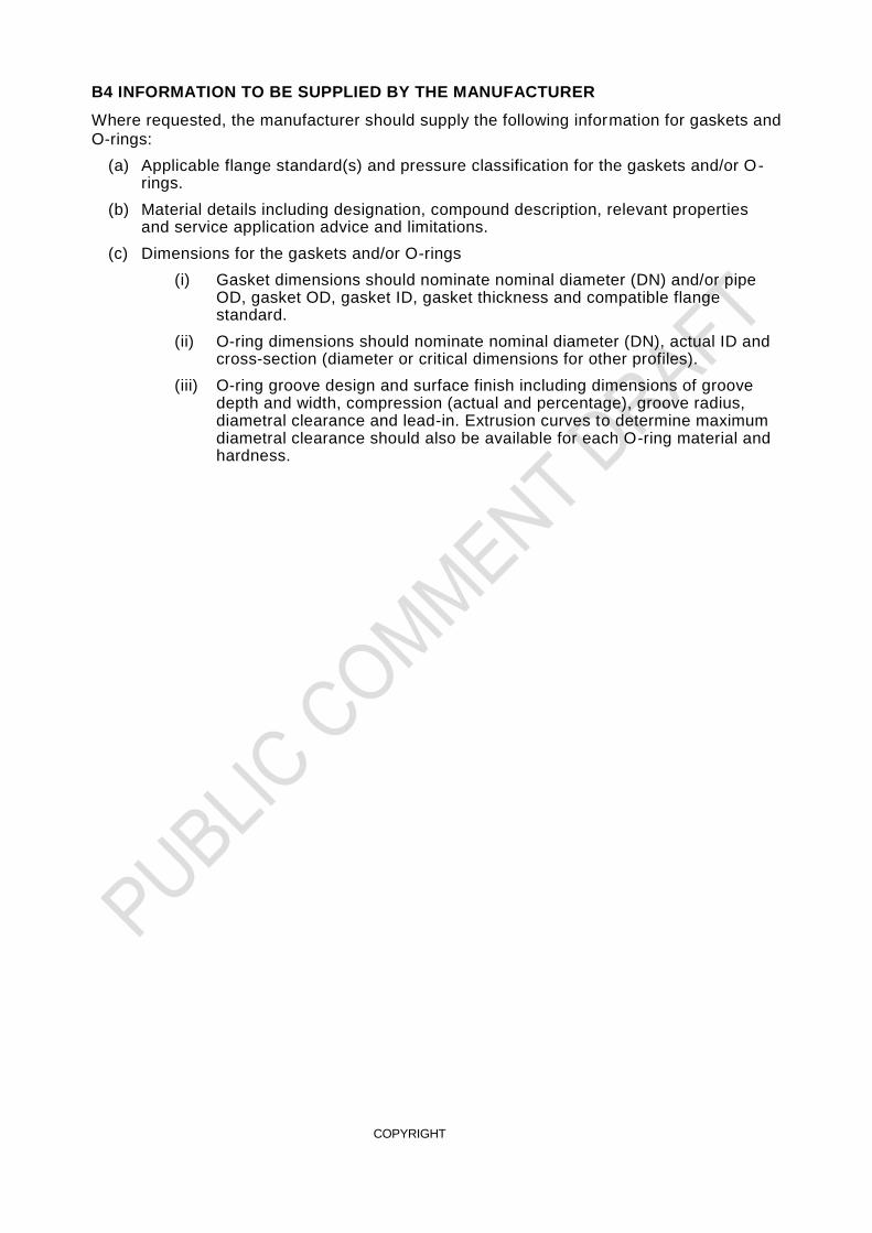
B4 INFORMATION TO BE SUPPLIED BY THE MANUFACTURER
Where requested, the manufacturer should supply the following information for gaskets and
O-rings:
(a) Applicable flange standard(s) and pressure classification for the gaskets and/or O-rings.
(b) Material details including designation, compound description, relevant properties and service application advice and limitations.
(c) Dimensions for the gaskets and/or O-rings
(i) Gasket dimensions should nominate nominal diameter (DN) and/or pipe OD, gasket OD, gasket ID, gasket thickness and compatible flange standard.
(ii) O-ring dimensions should nominate nominal diameter (DN), actual ID and cross-section (diameter or critical dimensions for other profiles).
(iii) O-ring groove design and surface finish including dimensions of groove depth and width, compression (actual and percentage), groove radius, diametral clearance and lead-in. Extrusion curves to determine maximum diametral clearance should also be available for each O-ring material and hardness.
COPYRIGHT
APPENDIX C
GASKET DIMENSIONS
(Normative)
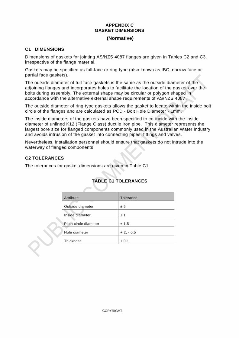
C1 DIMENSIONS
Dimensions of gaskets for jointing AS/NZS 4087 flanges are given in Tables C2 and C3,
irrespective of the flange material.
Gaskets may be specified as full-face or ring type (also known as IBC, narrow face or
partial face gaskets).
The outside diameter of full-face gaskets is the same as the outside diameter of the
adjoining flanges and incorporates holes to facilitate the location of the gasket over the
bolts during assembly. The external shape may be circular or polygon shaped in
accordance with the alternative external shape requirements of AS/NZS 4087.
The outside diameter of ring type gaskets allows the gasket to locate within the inside bolt
circle of the flanges and are calculated as PCD - Bolt Hole Diameter - 1mm.
The inside diameters of the gaskets have been specified to co-incide with the inside
diameter of unlined K12 (Flange Class) ductile iron pipe. This diameter represents the
largest bore size for flanged components commonly used in the Australian Water Industry
and avoids intrusion of the gasket into connecting pipes, fittings and valves.
Nevertheless, installation personnel should ensure that gaskets do not intrude into the
waterway of flanged components.
C2 TOLERANCES
The tolerances for gasket dimensions are given in Table C1.
TABLE C1 TOLERANCES
Attribute Tolerance
Outside diameter ± 5
Inside diameter ± 1
Pitch circle diameter ± 1.5
Hole diameter + 2, - 0.5
Thickness ± 0.1

COPYRIGHT
TABLE C2
FLANGE GASKET DIMENSIONS FOR AS/NZS 4087 PN 16 FLANGES
NOMINAL
SIZE MATERIAL
OD
mm ID
mm
NUMBER
OF
HOLES
PITCH
CIRCLE
DIAMETER
mm
HOLE
DIAMETER
mm Full Face Ring
80
Elastomeric
185 127 82 4 146 18
100 215 159 108 4 178 18
150 280 216 161 8 235 18
200 335 273 216 8 292 18
225 370 305 241 8 324 18
250 405 333 268 8 356 22
300 455 383 325 12 406 22
350 525 443 375 12 470 26
375 550 468 406 12 495 26
400 580 494 430 12 521 26
450 640 557 485 12 584 26
500 705 614 536 16 641 26
600 825 725 641 16 756 30
700 910 814 750 20 845 30
750 995 893 796 20 927 33
800
Compressed
Fibre
1060 947 860 20 984 36
900 1175 1055 970 24 1092 36
1000 1255 1138 1075 24 1175 36
1200 1490 1364 1290 32 1410 36
Thickness
mm Elastomeric 3 Compressed Fibre 1.5
COPYRIGHT
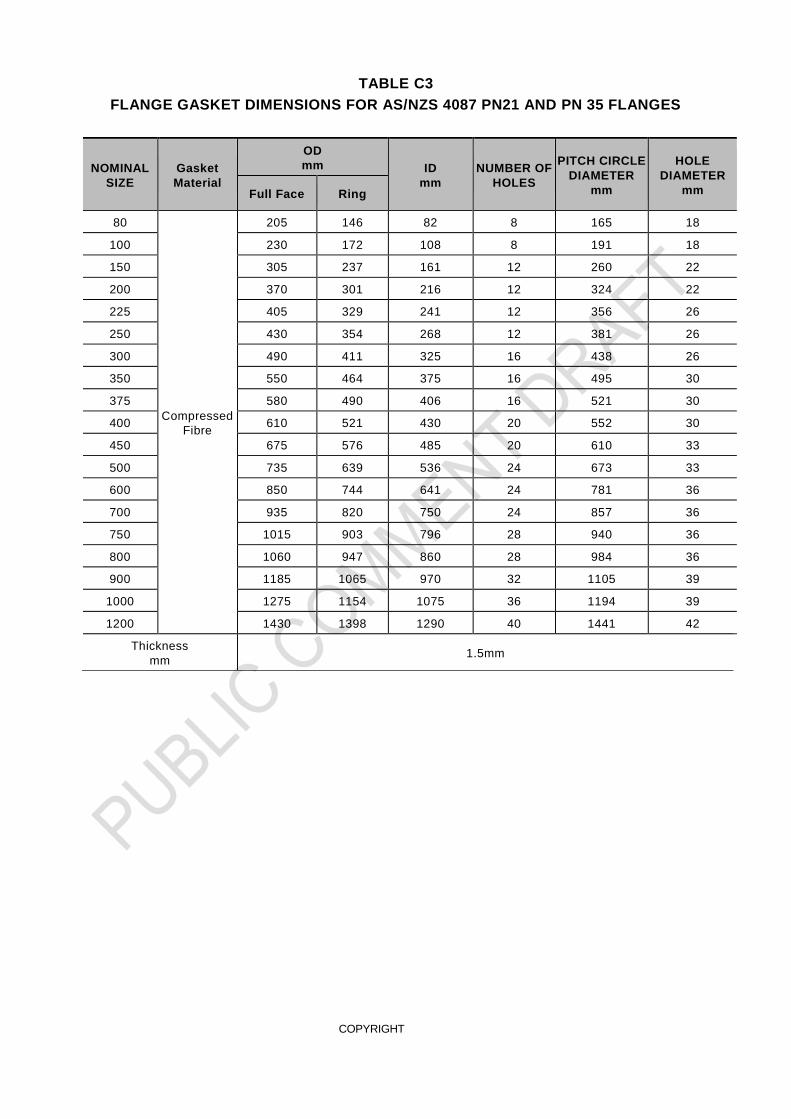
TABLE C3
FLANGE GASKET DIMENSIONS FOR AS/NZS 4087 PN21 AND PN 35 FLANGES
NOMINAL
SIZE
Gasket
Material
OD
mm ID
mm
NUMBER OF
HOLES
PITCH CIRCLE
DIAMETER
mm
HOLE
DIAMETER
mm Full Face Ring
80
Compressed
Fibre
205 146 82 8 165 18
100 230 172 108 8 191 18
150 305 237 161 12 260 22
200 370 301 216 12 324 22
225 405 329 241 12 356 26
250 430 354 268 12 381 26
300 490 411 325 16 438 26
350 550 464 375 16 495 30
375 580 490 406 16 521 30
400 610 521 430 20 552 30
450 675 576 485 20 610 33
500 735 639 536 24 673 33
600 850 744 641 24 781 36
700 935 820 750 24 857 36
750 1015 903 796 28 940 36
800 1060 947 860 28 984 36
900 1185 1065 970 32 1105 39
1000 1275 1154 1075 36 1194 39
1200 1430 1398 1290 40 1441 42
Thickness
mm 1.5mm

COPYRIGHT
APPENDIX D FLANGED JOINT ASSEMBLY
(Informative)
D1 SCOPE
This Appendix sets out recommendations, principles and procedures for the assembly of
AS/NZS 4087 metal flange joints in pipeline systems for water industry purposes.
Estimated tightening torques are provided in Tables D1, D2 and D3 based on methodology
and assumptions detailed in a spreadsheet calculator available from WSAA. (insert link)
Where alternative variables apply for a particular installation the spreadsheet calculator
may be used to estimate alternative tightening torques.
D2 DISCLAIMER
This Appendix has been prepared to assist engineers and contractors in the correct
assembly of flange joints and is not intended to be an exhaustive statement on flange joint
design or installation. Recommendations contained in this Appendix represent best
estimates only and may be based on assumptions which are not necessarily correct for
every installation.
Successful flange jointing depends on many factors outside the scope of this Appendix,
including site preparation and installation workmanship. It is recommended that users of
this Appendix should check technical developments from research and field experience
and utilise their knowledge, skill and judgement, particularly in regard to the quality and
suitability of the products and conditions surrounding each specific installation.
Water Agency or manufacturer’s codes, standards, specifications or drawings, if at
variance to any recommendation made in this Appendix, override any recommendations
made herein.
D3 FLANGED JOINTS
Flanged joints are completely rigid and should not be used for applications where
movement of the pipeline is expected, unless special provision is made to accommodate it
by, for example, the inclusion of expansion joints.
Flanged joints are used predominantly in above ground applications, e.g. pump stations,
water and sewage treatment plants and for pipeline networks. They are also commonly
used to facilitate the installation and removal of valves in elastomeric seal jointed and
welded pipelines and for valve bypass arrangements.
Where flanged joints are utilised in buried applications additional corrosion protection
systems should be considered.
Field welding or other special equipment is not required for the assembly of flanged joints.
Flanges are specified in accordance with AS/NZS 4087 with pressure classifications of PN
14, PN 16, PN 21 or PN 35.
Flanges may be supplied with a raised face or flat face, with or without an O-ring groove,
depending on the flange material and pressure classification. Details are given in AS/NZS
4087.
The most common flange joint types are shown in Figure D1 and D2.
Full-face gaskets are commonly used for jointing two raised face flanges or a flat face
flange to a raised face flange. Only the raised face area inside the bolt holes is clamped
during assembly.

COPYRIGHT
The use of ring type gaskets is recommended when jointing two flat face flanges.
FIGURE D1 O-RING FLANGED JOINT– STEEL SHOWN
FIGURE D2 RAISED FACE FLANGED JOINT– STEEL SHOWN
D4 GASKETS
Gaskets may be elastomeric or compressed fibre type.
AS/NZS 4087 Appendix C provides recommendations for the selection of appropriate
gasket materials (including thickness) for various metallic flange materials, pressure
classifications and flange face types.
It should be noted that where compressed fibre gaskets are used high strength fasteners
are required to accommodate the higher compression forces necessary for sealing.
D5 FASTENERS
Fasteners specified for jointing of flanges may be galvanised carbon steel or Grade 316
stainless steel.
AS/NZS 4087 Appendix C provides recommendations for the selection of appropriate
fasteners for various metallic flange materials, pressure classifications, flange face types
and recommended gasket material type.

COPYRIGHT
D6 ASSEMBLY OF FLANGED JOINTS
Successful flange assembly involves selection of the correct jointing materials and
competent installation in accordance with the principles detailed below.
The bolt acts like a spring. Bolt tensions are calculated to overcome the hydrostatic end
force generated by the internal fluid pressure trying to push the flanges apart in addition to
the force required to provide sufficient load on the gasket at the nominated internal
pressure, without exceeding the maximum allowable gasket stress at the time of
installation.
A torque wrench is most commonly utilized to achieve the required bolt tensions even
though it is commonly accepted that the use of a torque wrench to measure bolt tension
has an accuracy of only 25%.
The translation of torque to bolt tension is directly influenced by the nominated bolt torque
co-efficient, sometimes called the nut factor or k factor.
Torque = Bolt Tension x Bolt Diameter x k
The k factor is an assigned co-efficient to attempt to summarise the many variables that
may influence the torque-tension relationship. Such variables include fastener material,
coatings, surface finish and condition, thread form, efficacy of lubrication, speed and
continuity of assembly.
In most situations it is challenging to provide completely reliable torque values for bolted
assemblies. For enhanced accuracy the k factor for particular fasteners should be
determined experimentally.
Wherever possible it is recommended that a hydraulic tensioner be utilised to directly apply
the estimated bolt tensions.
Please note that is important to apply a good quality anti-seize compound to the moving
parts of the assembly including the contact surfaces between the threads and between the
nut, washer, bolt head and flange surfaces.
Tables D1 to D3 provides estimated torque requirements for jointing AS/NZS 4087 metal
flanges in acordance with the methodology and assumptions provided in a spreadsheet
calculator available from WSAA. (insert link)
D7 PRECAUTIONS
Bolts should be long enough to ensure that two complete threads are exposed when the
nut is tightened by hand.
A washer should be used under each bolt head and nut.
The flange jointing system should be correctly aligned in terms of parallelism and
concentricity.
Extra care needs to be taken when using stainless steel bolts as they are subject to
galling, which can significantly reduce bolt tension. The use of a nickel/graphite anti-seize
lubricant for both galvanised steel and stainless-steel bolts is recommended to achieve the
indicated k values. Note that copper based lubricants are not recommended for use with
staiinless steel fasteners.
The application of excessive torque at the time of installation may overstress the gasket or
O-ring causing crushing or extrusion, which can lead to leakage at operating pressures.
Excessive torques can also cause deformation of the flange material.
Special care should be taken when jointing screw-on flanges as excessive torques can
cause damage to the epoxy seal.

COPYRIGHT
D8 PROCEDURE
D8.1 JOINTING INSTRUCTIONS FOR FLANGED JOINTS
1 Use a scraper or wire brush to thoroughly clean the flange faces to be jointed,
ensuring there is no dirt, particles or foreign matter, protrusions or coating build-up on
the mating surfaces.
2 Ensure that the mating threads of all nuts and bolts are clean and in good condition.
3 Evenly apply a suitable lubricant (e.g. Loctite 771) to al l mating threads, including the
nut load bearing face and washer.
4 Align the flanges to be joined and ensure that the components are satisfactorily
supported to avoid bending stress on the flanged joint during and after assembly.
5 Insert four bolts in locations 1 to 4 as indicated in Figure E3 and position the gasket
on the bolts, taking care not to damage the gasket surface.
6 Offer the adjoining flange to the bolts, taking care to maintain support and alignment
of the components.
7 Tighten nuts to finger tight and check alignment of flange faces and gasket.
8 Insert the remaining bolts and tighten nuts to finger tight.
9 Estimate the required bolt torque considering bolt type and allowable tension, flange
type and rating, gasket material and maximum/minimum compression, and the
pipeline’s maximum pressure (operating/test pressure).
10 Tighten nuts to 20% of estimated torque using the star pattern as shown in Figure
D3.
11 Tighten to 50 % of estimated torque using the same tightening sequence.
12 Tighten to 75 % of estimated torque using the same tightening sequence.
13 Tighten to 100 % of estimated torque using the same tightening sequence.
14 Repeat the tightening procedure on all nuts until little or no movement can be
achieved on each nut (particularly important on elastomeric gaskets).
FIGURE D3 STAR PATTERN TIGHTENING SEQUENCE
D8.2 ESTIMATED TIGHTENING TORQUE VALUES
The estimated torques in Table D1 and Table D2 are based on gaskets specified within this
Standard and are intended to provide adequate gasket sealing stresses for internal
operating pressures ranging from zero to the allowable site test pressure (ASTP = 1.25 x
AOP) for AS/NZS 4087 metallic flanges, regardless of flange material. Table D3 provides

COPYRIGHT
estimated torques for flat face flanges with O-ring sealing and are based on 65 % of the
fastener proof load.
Nominated fastener torque co-efficients or k factors are indicated for the fastener materials
that are assumed to be well lubricated. Well lubricated refers to the use of anti-seize
treatments such as PTFE coatings and application of good quality nickel based anti-seize
compounds.
The torques are estimated for raised face, flat face and O-ring type flanges with common
surface finishes used in the water industry with an assumed surface roughness of Ra = 10
– 12 µm.
Full face gaskets or ring type gaskets may be used when jointing raised face flanges,
however only ring type gaskets are recommended for use with full face flanges.
Where an alternative internal pressure or k factor applies, alternative bolt tensions and
torques should be calculated. A spreadsheet calculator is available from WSAA.
TABLE D1
ESTIMATED TIGHTENING TORQUES FOR AS 4087 PN 16 FLANGES
Nominal Size
DN
Fastener Size Number of
Fasteners
Fastener
Tension
kN
Gal / SS
Estimated Torques
Nm
Well-lubricated
Grade 4.6
galvanized steel
fasteners
k = 0.15
Well-lubricated
Grade 316 Class
50 stainless steel
fasteners
k = 0.20
80 M16 4 20 50 65
100 M16 4 20 50 65
150 M16 8 20 50 65
200 M16 8 25 60 80
225 M16 8 25 60 80
250 M20 8 35 105 140
300 M20 12 35 105 140
350 M24 12 50 180 240
375 M24 12 50 180 240
400 M24 12 50 180 240
450 M24 12 55 200 265
500 M24 16 55 200 265
600 M27 16 70 285 380
700 M27 20 60 245 325
750 M30 20 80 360 480
800 M33 20 240 / 200 11902 13202
900 M33 24 240 / 200 11902 13202
1000 M33 24 240 / 200 11902 13202
1200 M33 32 240 /200 11902 13202
NOTE:
1.For DN 80 to DN 750 use Grade 4.6 galvanised carbon steel or Grade 316 Class 50 stainless steel
fasteners with 3 mm thick elastomeric gasket
2.For DN > 750 use Grade 8.8 galvanised carbon steel or Grade 316 Class 70 stainless steel fasteners with
1.5mm compressed fibre gasket.
COPYRIGHT
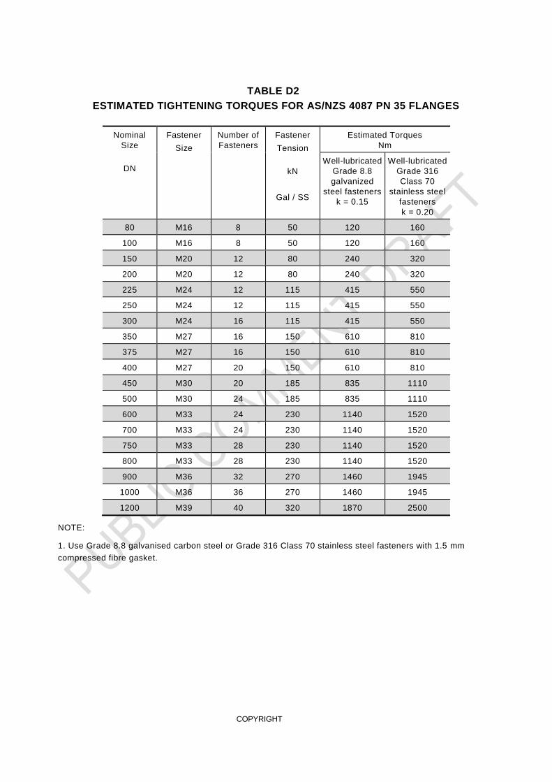
TABLE D2
ESTIMATED TIGHTENING TORQUES FOR AS/NZS 4087 PN 35 FLANGES
Nominal
Size
DN
Fastener
Size
Number of
Fasteners
Fastener
Tension
kN
Gal / SS
Estimated Torques
Nm
Well-lubricated
Grade 8.8
galvanized
steel fasteners
k = 0.15
Well-lubricated
Grade 316
Class 70
stainless steel
fasteners
k = 0.20
80 M16 8 50 120 160
100 M16 8 50 120 160
150 M20 12 80 240 320
200 M20 12 80 240 320
225 M24 12 115 415 550
250 M24 12 115 415 550
300 M24 16 115 415 550
350 M27 16 150 610 810
375 M27 16 150 610 810
400 M27 20 150 610 810
450 M30 20 185 835 1110
500 M30 24 185 835 1110
600 M33 24 230 1140 1520
700 M33 24 230 1140 1520
750 M33 28 230 1140 1520
800 M33 28 230 1140 1520
900 M36 32 270 1460 1945
1000 M36 36 270 1460 1945
1200 M39 40 320 1870 2500
NOTE:
1. Use Grade 8.8 galvanised carbon steel or Grade 316 Class 70 stainless steel fasteners with 1.5 mm
compressed fibre gasket.

COPYRIGHT
TABLE D3
ESTIMATED TIGHTENING TORQUES FOR FLAT FACE FLANGES WITH O-RING
Fastener
Size
Estimated Torques Nm
PN 16 PN 35 PN 16 PN 35
Well-lubricated galvanized
steel fasteners
k = 0.15
Well-lubricated Grade 316
stainless steel fasteners
k = 0.20
M16 55 140 70 150
M20 110 290 135 290
M24 185 500 230 495
M27 270 725 340 725
M30 370 985 460 985
M33 510 1340 625 1340
M36 - 1720 - 1720
M39 - 2230 - 2230
NOTE:
1. Torques are calculated to achieve 65 % proof load of the applicable fastener.

COPYRIGHT
Melbourne Office Level 8, Suite 8.02 401 Docklands Drive Docklands VIC 3008 Sydney Office Level 9 420 George Street Sydney NSW 2000 GPO Box 915 Sydney NSW 2001 P +61 (0) 3 8605 7666 email: [email protected]
www.wsaa.asn.au
Recommended