Dr. Ikbal Bahar Laskar
Workshop Theory and Practice-I
Prepared By:
Ikbal Bahar Laskar
Department of Mechanical Engineering
Jorhat Engineering College (JEC), Jorhat, Assam, India

Dr. Ikbal Bahar Laskar
01-08-2021 Jorhat Engineering College, Jorhat, Assam, India
PATTERN MAKING AND FOUNDRY
Pattern making and sand casting – Pattern materials – Types – Pattern allowances. Core prints.
Moulding sand – ingredients – classification – sand additives – properties of moulding sand –
sand preparation and testing. Green sand mould preparation. Cores and core making – Types of
cores.
Syllabus Module 6

Dr. Ikbal Bahar Laskar
01-08-2021 Jorhat Engineering College, Jorhat, Assam, India
Casting
Casting is a manufacturing process in which a liquid material is usually poured into a mold, which contains a hollow cavity of
the desired shape, and then allowed to solidify. The solidified part is also known as a casting, which is ejected or broken out of
the mold to complete the process.
Casting

Dr. Ikbal Bahar Laskar
01-08-2021 Jorhat Engineering College, Jorhat, Assam, India
Casting
Casting Product
Step of sand casting

Dr. Ikbal Bahar Laskar
01-08-2021 Jorhat Engineering College, Jorhat, Assam, India
Casting process
1. Sand casting
2. Investment casting
3. Die casting
4. Low pressure casting
5. Centrifugal casting
6. Gravity die casting
7. Vacuum die casting
8. Squeezing die casting
9. Lost foam casting
10. Continual casting
Lost foam casting product

Dr. Ikbal Bahar Laskar
01-08-2021 Jorhat Engineering College, Jorhat, Assam, India
Pattern In casting, a pattern is a replica of the object to be cast, used to prepare the cavity into which molten material will be poured during the
casting process.
Patterns used in sand casting may be made of wood, metal, plastics or other materials. Patterns are made to exacting standards of construction,
so that they can last for a reasonable length of time, according to the quality grade of the pattern being built, and so that they will repeatably
provide a dimensionally acceptable casting.

Dr. Ikbal Bahar Laskar
01-08-2021 Jorhat Engineering College, Jorhat, Assam, India
Pattern

Dr. Ikbal Bahar Laskar
01-08-2021 Jorhat Engineering College, Jorhat, Assam, India
Pattern material
The selection of pattern materials depends primarily on the following factors
1. service requirements, eg. Quantity, quality and intricacy of casting i.e., minimum thickness desired, degree of accuracy and finish required.
2. Type of production of castings and type of moulding process.
3. Possibility of design changes.
4. Number of castings to be produced, i.e possibility of repeat orders

Dr. Ikbal Bahar Laskar
01-08-2021 Jorhat Engineering College, Jorhat, Assam, India
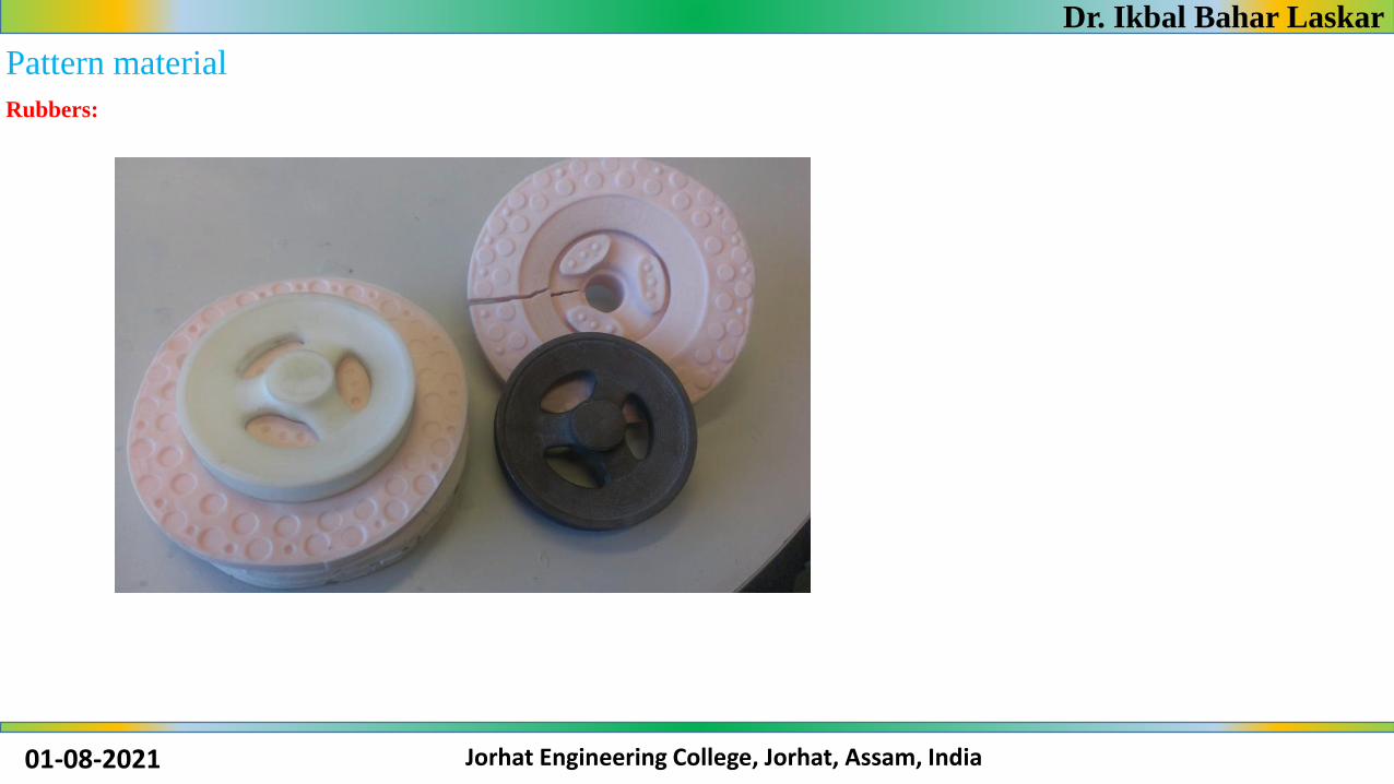
Pattern material
The wide variety of pattern materials which meet these characteristics are wood and wood products; metals and alloys; plasters; plastics and
rubbers; waxes.
Wood: wood is the most common material for pattern as it satisfy many of the aforesaid requirements. It is easy to work and readily available.
Wood can be cut and fabricated i8nto numerous forms by glueing, bending and curving.
Wooden patterns

Dr. Ikbal Bahar Laskar
01-08-2021 Jorhat Engineering College, Jorhat, Assam, India
Pattern material
Metal: metal is used when large number of casting are desired from a pattern or when conditions are too severe for wooden pattern. Metal
patterns do not change their shape when subject to moist conditions. Another advantage of metal pattern is freedom from warping in shortage.
Metal patterns are very useful in machine moulding because of their accuracy, durability and strength.
Commonly, a metal pattern is cast from wooden pattern called master pattern

Dr. Ikbal Bahar Laskar
01-08-2021 Jorhat Engineering College, Jorhat, Assam, India
Pattern material
Plastics:
Plastics are now finding their place as a modern pattern material because they do not absorb moisture, are strong and dimensionally stable,
resistant to wear, have a very smooth and glossy surfaceand are leight in weight. because of its glossy surface it can be withdrawn from the
mould very easily without injuring the mould and dry or liquid parting compound is necessary.
Dr. Ikbal Bahar Laskar
01-08-2021 Jorhat Engineering College, Jorhat, Assam, India
Pattern material
Rubbers:

Dr. Ikbal Bahar Laskar
01-08-2021 Jorhat Engineering College, Jorhat, Assam, India
Types of pattern
1. Single piece pattern
2. Split pattern
3. Match plate pattern
4. Cope and drag pattern
5. Gated pattern
6. Loose piece pattern
7. Sweep pattern
8. Skeleton pattern
9. Segmental pattern
10. Shell pattern
11. Built up pattern
12. Bo9xed up pattern
13. Lagged up pattern
14. Left and ri8ght hand pattern

Dr. Ikbal Bahar Laskar
01-08-2021 Jorhat Engineering College, Jorhat, Assam, India
Types of pattern
Single piece pattern:
A pattern that is made without joints, partings or any loose pieces in its construction is called a single piece or solid pattern.
A single piece pattern is not attached to a frame or plate and is, therefore , sometimes known as loose pattern.
These patterns are cheaper. When using such patterns the moulder has to cut his own runners and feeding gates and risers.
These operation takes more time, and they are not recommended except for limited production. Single piece patterns are usually used for large
castings of simple shapes.

Dr. Ikbal Bahar Laskar
01-08-2021 Jorhat Engineering College, Jorhat, Assam, India
Types of patternSplit pattern
This is a pattern that is made in two halves split along the parting line. The two halves are held in register by pins called pattern
dowels. The pattern is split to facilitate molding.
The dowels hold the two halves of the pattern together in close accurate register, but at the same time are free enough that the
two halves can be separated easily for molding. Like the pins and guides of the flask.
The dowels are usually installed off center in such a manner that the pattern can only be put together correctly.
A dowel is a solid cylindrical rod, usually made of wood, plastic or metal. In its original manufactured form, dowel is called dowel
rod.

Dr. Ikbal Bahar Laskar
01-08-2021 Jorhat Engineering College, Jorhat, Assam, India
Types of patternMatch plate Pattern
When split patterns are mounted with on one half on one side of a plate and the other half directly opposite on other side of the
pattern, the pattern is called a match plate pattern. A single pattern or a number of pattern may be mounted on match plate. The
pattern is made of metal and the plate which makes the parting line may be either made of wood or metal. When the match plate
is lifted off the mold all patterns are drawn

Dr. Ikbal Bahar Laskar
01-08-2021 Jorhat Engineering College, Jorhat, Assam, India
Types of patternCOPE AND DRAG PATTERN
In the simplest sand casting procedure, the drag is placed upside down on a board, around a pattern of the part to be cast. The pattern
is a model of the desired casting. Talcum powder is often dusted over the pattern to aid in the removal of the pattern. Sand is sifted
over the pattern until the model is covered by a few inches of sand. More sand is then dumped into the drag, and rammed with a
wooden wedge, or mechanically vibrated to pack the sand down. The sand is then struck level with the top edge of the cope, using a
wooden or metal strake. A board is then placed on top of the drag and the drag is flipped over.
Then, the cope is placed on the drag, and dowels (or pins) are put in the sand to make holes for the sprue and one or more risers.
Talcum powder and sand are again sifted over the pattern, and rammed to fill the cope. The pins are then carefully pulled out of the
sand. The critical part of the operation is to separate the cope and drag to remove the pattern. The pattern may be vibrated with a
powered vibrator, or the pattern, and maybe the cope and drag flask, will be lightly tapped with a small hammer. The pattern is lifted
from the sand, leaving a molding cavity. A passageway for metal to enter the mold, called a "gate", is then cut from the sprue hole to
the void left by the pattern, and a runner is cut from the sand to allow metal to flow into the riser

Dr. Ikbal Bahar Laskar
01-08-2021 Jorhat Engineering College, Jorhat, Assam, India
Types of patternCOPE AND DRAG PATTERN
Dr. Ikbal Bahar Laskar
01-08-2021 Jorhat Engineering College, Jorhat, Assam, India
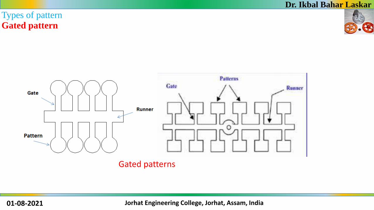
Types of patternGated pattern
Gated patterns

Dr. Ikbal Bahar Laskar
01-08-2021 Jorhat Engineering College, Jorhat, Assam, India
Types of patternLoose piece pattern

Dr. Ikbal Bahar Laskar
01-08-2021 Jorhat Engineering College, Jorhat, Assam, India
Types of patternSweep Pattern

Dr. Ikbal Bahar Laskar
01-08-2021 Jorhat Engineering College, Jorhat, Assam, India
Types of patternSkeleton pattern
Skeleton pattern

Dr. Ikbal Bahar Laskar
01-08-2021 Jorhat Engineering College, Jorhat, Assam, India
Types of patternSegmental pattern

Dr. Ikbal Bahar Laskar
01-08-2021 Jorhat Engineering College, Jorhat, Assam, India
Types of patternShell pattern
Shell pattern is used largely for drainage fittings and pipe work. The
pattern is usually made of metal, mounted on a plate and parted
along the center line, the two sections being doweled together.
These short bends are usually moulded and cast in pairs. The shell
pattern is a hollow construction li8ke a shell and the outside shape is
used as a pattern to make the mould, while the inside is used as a core
box for making cores.
Sometimes, a pattern of the entire shape of casting is termed a shell
pattern, and a pattern that is of the required shape outside, but
having the inside cored out is termed a block pattern.

Dr. Ikbal Bahar Laskar
01-08-2021 Jorhat Engineering College, Jorhat, Assam, India
Types of patternBuilt up pattern
As the name implies, built up pattern or parted patterns are composed of two or more pieces.
Patterns for special pulleys are built up segments of wooden strips.
These segments are made by cutting strips of wood strips of wood to the curvature required, and the thickness desired is built up by gluing
them in layers.
Flanges are also made similarly. The built up is sometimes necessary because it is difficult to make an intricate shape on a block of wood for
constructing a pattern, but it is easier to build up the shape by glueing or joining number segmental pieces together.

Dr. Ikbal Bahar Laskar
01-08-2021 Jorhat Engineering College, Jorhat, Assam, India
Types of pattern
Lagged up pattern
Cylindrical works such as cylinders pipes or columns are built up
with lag or stave construction which ensures permanence of form.
“Lags” or “staves” are longitudinal strips of wood which are
beveled on each side to make the joint tight outside, and glued and
nailed or screwed to the end pieces of wood called “heads”. The
Fig.12 shows the staves fastened to heads that are half a regular
polygon, the object being to make a cylinder or barrel that is to be
parted longitudinally through the center. Such a construction gives
the maximum amount of strength and permits building close to the
finished outline of the pattern so that there is comparatively little
excess stock to be removed to bring it to the required form.Lagged up pattern
Dr. Ikbal Bahar Laskar
01-08-2021 Jorhat Engineering College, Jorhat, Assam, India
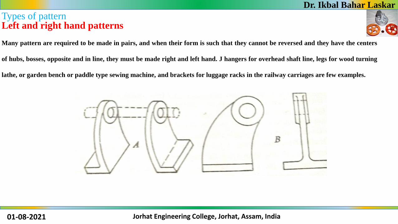
Types of patternLeft and right hand patterns
Many pattern are required to be made in pairs, and when their form is such that they cannot be reversed and they have the centers
of hubs, bosses, opposite and in line, they must be made right and left hand. J hangers for overhead shaft line, legs for wood turning
lathe, or garden bench or paddle type sewing machine, and brackets for luggage racks in the railway carriages are few examples.

Dr. Ikbal Bahar Laskar
01-08-2021 Jorhat Engineering College, Jorhat, Assam, India
Pattern making allowances
Patterns are not made the exact same size as the desired casting for several reasons. Such a pattern would produce castings
which are undersize.
Allowance must be therefore be allowed for shrinkage, draft, finish, distortion, and rapping
Shrinkage allowance:
As metal solidifies and cool , it shrinks and contracts in size. To compensate for this, a pattern is made larger than the
finished casting by means of a shrinkage or contraction allowance. In laying measurements for the pattern the
patternmaker allows for this by using shrink and contraction rule which is slightly longer than the ordinary rule of the
same length.
Dr. Ikbal Bahar Laskar
01-08-2021 Jorhat Engineering College, Jorhat, Assam, India
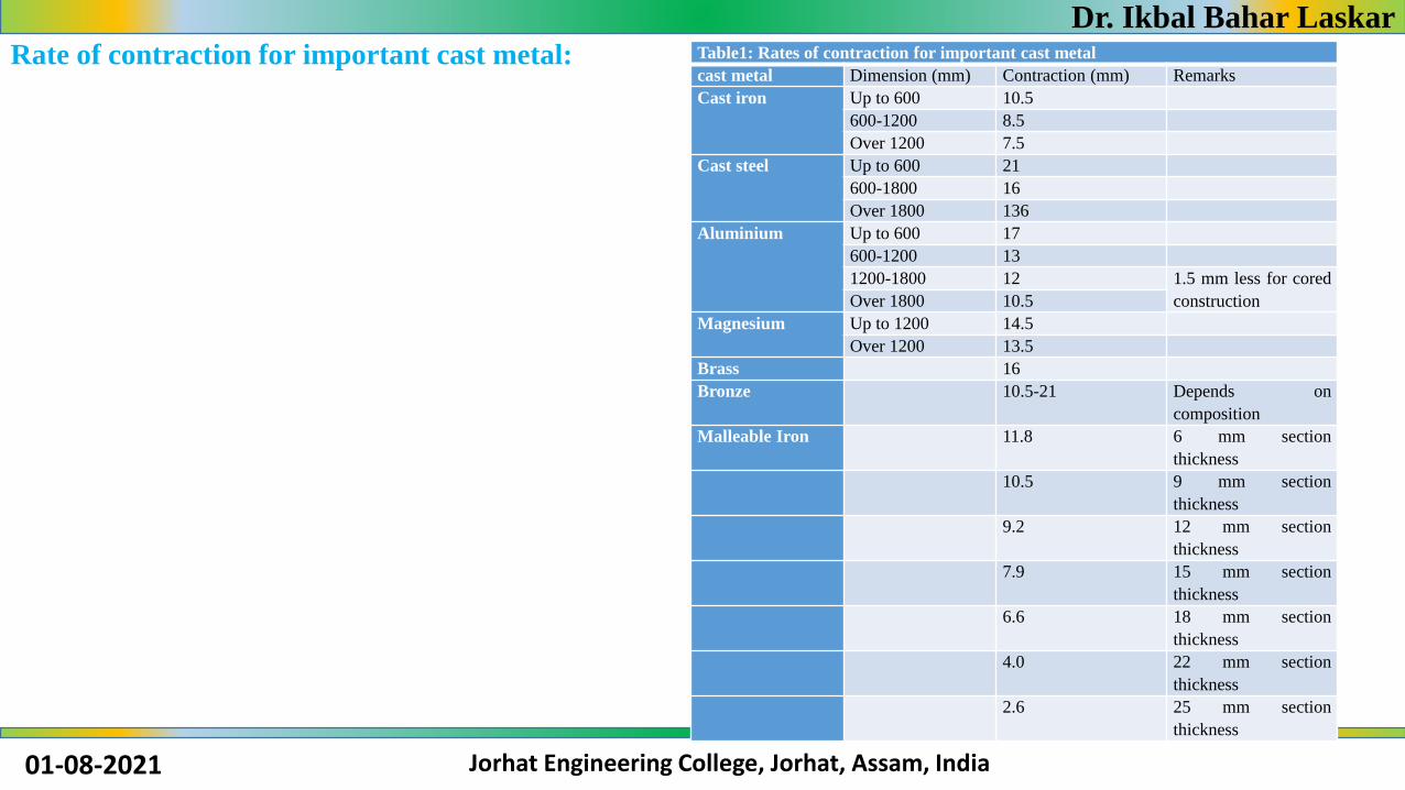
Rate of contraction for important cast metal: Table1: Rates of contraction for important cast metal
cast metal Dimension (mm) Contraction (mm) Remarks
Cast iron Up to 600 10.5
600-1200 8.5
Over 1200 7.5
Cast steel Up to 600 21
600-1800 16
Over 1800 136
Aluminium Up to 600 17
600-1200 13
1200-1800 12 1.5 mm less for cored
constructionOver 1800 10.5
Magnesium Up to 1200 14.5
Over 1200 13.5
Brass 16
Bronze 10.5-21 Depends on
composition
Malleable Iron 11.8 6 mm section
thickness
10.5 9 mm section
thickness
9.2 12 mm section
thickness
7.9 15 mm section
thickness
6.6 18 mm section
thickness
4.0 22 mm section
thickness
2.6 25 mm section
thickness
Dr. Ikbal Bahar Laskar
01-08-2021 Jorhat Engineering College, Jorhat, Assam, India
Pattern making allowances
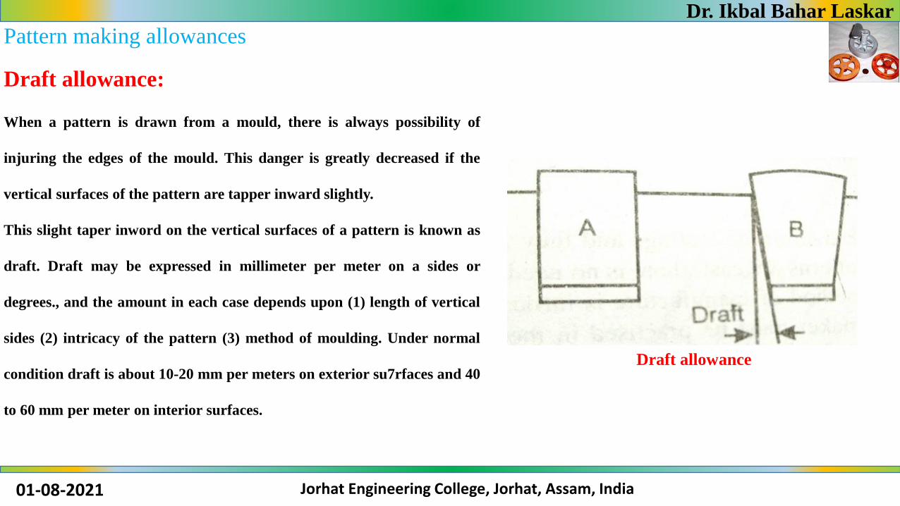
Draft allowance:
When a pattern is drawn from a mould, there is always possibility of
injuring the edges of the mould. This danger is greatly decreased if the
vertical surfaces of the pattern are tapper inward slightly.
This slight taper inword on the vertical surfaces of a pattern is known as
draft. Draft may be expressed in millimeter per meter on a sides or
degrees., and the amount in each case depends upon (1) length of vertical
sides (2) intricacy of the pattern (3) method of moulding. Under normal
condition draft is about 10-20 mm per meters on exterior su7rfaces and 40
to 60 mm per meter on interior surfaces.
Draft allowance
Dr. Ikbal Bahar Laskar
01-08-2021 Jorhat Engineering College, Jorhat, Assam, India
Pattern making allowances
Machining allowance :
Rough surfaces of castings that has to be machined are made to dimensions somewhat over those indicated on the finished
working drawings. The extra amount of metal provided on the surfaces to be machined is called machine finish allowance
and the edges of these surfaces are indicated by V or F. the amount that is to be added to the patterns depends upon (1) the
kind of metal to be used, (2) the size and shape of the casting and (3) method of moulding

Dr. Ikbal Bahar Laskar
01-08-2021 Jorhat Engineering College, Jorhat, Assam, India
Pattern making allowances
Standard Machining allowance :
Table2: Standard Machining allo0wance
Diameter of
hole/distance
from locating
point (mm)
Cast iron
(mm)
Cast steel (mm) Nonferous
(mm)
Bore Surfa
ces
Bore Surfac
es
Bore Surfac
es
200 3 3 4 4 1.5-2 1.5
200-400 4.5 4 5.5 5 2.0 1.5
400-700 6 5 7 6 3.0 2.0
700-1100 7 6 9 7 3.5 2.5
1100-1600 9 7 11 9 4.0 3.0
1600-2200 10 8 13 11 -- --
2200-3000 12 9 15 13 -- --

Dr. Ikbal Bahar Laskar
01-08-2021 Jorhat Engineering College, Jorhat, Assam, India
Pattern making allowances
Distortion or camber allowance :
Some castings, because of their size, shape and type of metal, tend to warp or distort during during the cooling period. This
is a result of uneven shrinkage and is due to uneven metal thickness or to one surface being more exposed than another,
causing it to cool more rapidly.
The shape of the pattern is thus bent in the opposite direction to overcome this distortion. As an example, a casting shaped
like the letter U will be distorted with the legs diverging, instead of parallel . To compensate for this condition, the pattern is
made in such a manner that the legs converge but as the casting cools after its removal from the mould, the legs straighten
and remain parallel.

Dr. Ikbal Bahar Laskar
01-08-2021 Jorhat Engineering College, Jorhat, Assam, India
Pattern making allowances
Rapping allowance :
When a pattern is rapped in the mould before it is withdrawn, the cavity in the mould is slightly increased. In every cases
where castings must be uniform and true to pattern slightly smaller than the actual size to compensate for the rapping of
the mould
Dr. Ikbal Bahar Laskar
01-08-2021 Jorhat Engineering College, Jorhat, Assam, India
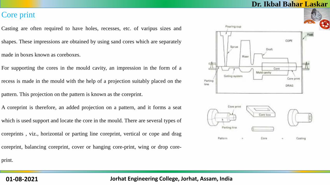
Core print
Casting are often required to have holes, recesses, etc. of varipus sizes and
shapes. These impressions are obtained by using sand cores which are separately
made in boxes known as coreboxes.
For supporting the cores in the mould cavity, an impression in the form of a
recess is made in the mould with the help of a projection suitably placed on the
pattern. This projection on the pattern is known as the coreprint.
A coreprint is therefore, an added projection on a pattern, and it forms a seat
which is used support and locate the core in the mould. There are several types of
coreprints , viz., horizontal or parting line coreprint, vertical or cope and drag
coreprint, balancing coreprint, cover or hanging core-print, wing or drop core-
print.

Dr. Ikbal Bahar Laskar
01-08-2021 Jorhat Engineering College, Jorhat, Assam, India
Core print
Horizontal core print
Vertical core print
Balancing core print
Hanging or cover core print
Wing or drop core print
Balanced Core Vertical CoreHorizontal core prints

Dr. Ikbal Bahar Laskar
01-08-2021 Jorhat Engineering College, Jorhat, Assam, India
Horizontal core print
This is laid horizontally in the mould and is located at the parting line of the mould. The core print is often found
on the split or two- piece pattern. When it is important that certain core be located at a desired angular relationship
with respect to the central axis, a flat portion at one end is made to coincide with a flat portion of the core print.
Horizontal core print

Dr. Ikbal Bahar Laskar
01-08-2021 Jorhat Engineering College, Jorhat, Assam, India
Vertical core print
This stands vertically in the mould. This is why this type of core is referred to to as a vertical core print. The core
print is located on the cope and drag sides of a pattern and is constructed with considerable taper specially on the
cope side (about 10-15 deg) so that they are easily moulded. The taper on drag print is only 1.5-3 deg.
Vertical core print

Dr. Ikbal Bahar Laskar
01-08-2021 Jorhat Engineering College, Jorhat, Assam, India
Balancing core print
This is used when a horizontal core does not extend entirely through the casting, and the core is supported at one end
only. An important feature of this core print is that the print of the core in the mould cavity should balance the part
which rests in the core seat.
Balancing core print

Dr. Ikbal Bahar Laskar
01-08-2021 Jorhat Engineering College, Jorhat, Assam, India
Hanging or cover coreprint
This is used when the entire pattern is rammed in the drag and the core is required to be suspended from top of the mould. In
this case, the cores serve as a cover for the mould, and also as a support for hanging the main body of a core.

Dr. Ikbal Bahar Laskar
01-08-2021 Jorhat Engineering College, Jorhat, Assam, India
Wing or drop core print
This is used when the cavity to be cored is above or below the parting line in the mould. Wing core prints are also known as
“chair”, and “tail” core prints.
Wing or drop core print

Dr. Ikbal Bahar Laskar
01-08-2021 Jorhat Engineering College, Jorhat, Assam, India
Core boxes
A core box is essentially a type of pattern made of wood or metal into which sand is rammed or packed to form a core. The types of
core boxes, in common use, in foundry work, are described below.
Half box
Dump box
Split box
Right and left hand box
Gang box
Core box with loose pieces
Sweep and skeleton box

Dr. Ikbal Bahar Laskar
01-08-2021 Jorhat Engineering College, Jorhat, Assam, India
Half core box
This is the most common type of core box. The two identical halves of a symmetrical core prepared in the half core box
are shown in Fig. Two halves of cores are pasted or cemented together after baking to form a complete core.
Half core box

Dr. Ikbal Bahar Laskar
01-08-2021 Jorhat Engineering College, Jorhat, Assam, India
Dump core box
Dump core box is similar in construction to half core box as shown in Fig. The cores produced do not require pasting, rather they
are complete by themselves. If the core produced is in the shape of a slab, then it is called as a slab box or a rectangular box. A
dump core-box is used to prepare complete core in it. Generally cylindrical and rectangular cores are prepared in these boxes.

Dr. Ikbal Bahar Laskar
01-08-2021 Jorhat Engineering College, Jorhat, Assam, India
Split core box
Split core boxes are made in two parts as shown in Fig. They form the complete core by only one ramming. The two
parts of core boxes are held in position by means of
clamps and their alignment is maintained by means of dowel pins and thus core is produced

Dr. Ikbal Bahar Laskar
01-08-2021 Jorhat Engineering College, Jorhat, Assam, India
Right and left hand core box
Some times the cores are not symmetrical about the center line. In such cases, right and left hand core boxes are used. The
two halves of a core made in the same core box are not identical and they cannot be pasted together.

Dr. Ikbal Bahar Laskar
01-08-2021 Jorhat Engineering College, Jorhat, Assam, India
Strickle core box
This type of core box is used when a core with an irregular shape is desired. The required shape is achieved by striking oft
the core sand from the top of the core box with a wooden piece, called as strickle board. The strickle board has the same
contour as that of the required core.

Dr. Ikbal Bahar Laskar
01-08-2021 Jorhat Engineering College, Jorhat, Assam, India
Gang core box
Some times the cores are not symmetrical about the center line. In such cases, right and left hand core boxes are used. The
two halves of a core made in the same core box are not identical and they cannot be pasted together.
Gang core box

Dr. Ikbal Bahar Laskar
01-08-2021 Jorhat Engineering College, Jorhat, Assam, India
Loose piece core box
Loose piece core boxes are highly suitable for making cores where provision for bosses, hubs etc. is required. In such cases,
the loose pieces may be located by dowels, nails and dovetails etc. In certain cases, with the help of loose pieces, a single
core box can be made to generate both halves of the right-left core.

Dr. Ikbal Bahar Laskar
01-08-2021 Jorhat Engineering College, Jorhat, Assam, India
Core Box Allowances
Materials used in making core generally swell and increase in size. This may lead to increase the size of core. The larger
cores sometimes tend to become still larger.
This increase in size may not be significant in small cores, but it is quite significant in large cores and therefore certain
amount of allowance should be given on the core boxes to compensate for this increase the cores.
It is not possible to lay down a rule for the amount of this allowance as this will depend upon the material used, but it is
customary to give a negative allowance of 5 mm /mt

Dr. Ikbal Bahar Laskar
01-08-2021 Jorhat Engineering College, Jorhat, Assam, India
Colour coding for patterns and core boxes
All surfaces of a wooden pattern are coated with shellac to keep out moisture and important parts of a pattern and core box
are coloured for identification of their different parts. A widely accepted colour code for general use is given below.
1. Surfaces to be left unfinished are to be painted black
2. Surfaces to be machined are to be painted red
3. Seats for loose- pieces are to be marked by red stripes on a yellow background
4. Coreprints are to be painted yellow
5. Stop-offs are to be marked by diagonal black stripes on yellow base
Thin wooden patterns often need to be secured against distortion by means of a tie bar.
This tie bar is molded but must not be cast. The corresponding mold cavity must be closed off with mold material.
Such components are referred to as stop-offs and marked on the pattern by means of black diagonal lines

Dr. Ikbal Bahar Laskar
01-08-2021 Jorhat Engineering College, Jorhat, Assam, India
Colour coding for patterns and core boxes

Dr. Ikbal Bahar Laskar
01-08-2021 Jorhat Engineering College, Jorhat, Assam, India
Moulding Sands
The principal material used in the in the foundry shop for moulding is the sand. This is because it possesses the properties
vital for foundry purposes.
Sources: All sands are formed by the breaking up of rocks due to the action of natural forces such as frost, wind, rain, heat
and water current. Rocks however, are very complex in their composition, and sands contain most of the elements of the
rocks of which they are fragments. For the reason, moulding sands in different parts of the world vary considerably. Today,
sand is obtained from places which probably once were bottoms and banks of rivers and sand dunes.
In india, foundary sand are found in damodar and barakar area, santhal paragana (Bihar), Londha (Maharastra), Batala
(Gurdaspur, Punjuab), Bhavnagar (Saurashtra), Londha (Maharastra), Avadi and Veeriyambakam (Madras), Kanpur,
Jabalpur, Rajkot, Guntur and many other places.

Dr. Ikbal Bahar Laskar
01-08-2021 Jorhat Engineering College, Jorhat, Assam, India
Principal Ingredients
The principal ingredients of moulding sands are: (1) silica sand grains, (2) clay (3) moisture, and (4) miscellaneous materials
Silica in the form of granular quartz, itself a sand is the chief constituent of moulding sand. Silica sand contains from 80-90
percent silicon dioxide and is characterized by a high softening temperature and thermal stability.
Clay: clay is defined as those particles of sand (under 20 microns in diameter) that fail to settle at arate of 25 mm per
minute, when syspended in water. Clay consist of two ingredients: fine slit and true clay.
Moisture, in requisite amount, furnishes the bonding action of clay, when water is added to clay, it penetrates the mixture
and forms a microfilm which coats the surface of flake-shaped clay particles. The bonding action is considered best if the
water added is the exact quantity required to form the film. On the other hand, the bonding action is reduced and the mould
gets weakened if the water is in excess. The water should be between 2 and 8 percent
Miscellaneous materials that are found, in addition to silica and clay, in moulding sand are oxide of iron, limestone,
magnesia, soda, and potash. The impurities should be 2 percent.

Dr. Ikbal Bahar Laskar
01-08-2021 Jorhat Engineering College, Jorhat, Assam, India
Moulding sand
Moulding sands may be classified generally into three different types: (1) natural moulding sands, (2) synthetic or high silica
sands and (3) special sands
Types of moulding sand1. Green sand2. Dry sand3. Loam sand4. Facing sand5. Backing sand6. System sand7. Parting sand8. Core sand

Dr. Ikbal Bahar Laskar
01-08-2021 Jorhat Engineering College, Jorhat, Assam, India
Green sand
The green sand is the natural sand containing sufficient moisture in it. It is mixture of silica and 18 to 30% clay with about
6-8% water. Clay and water act as a bonding material to give strength. Molds made from this sand are known as green sand
mould. The green sand is used only for simple and rough casting products. It is used for both ferrous and non-ferrous metals
Dry sand
When the moisture is removed from green sand, it is known as dry sand. The mould produced by dry sand has greater strength,
rigidity and thermal stability. This sand is used for large and heavy castings
Loam sand is a mixture of 50 percent sand and 50 percent clay. Water is added in sufficient amount. It is used for large and
heavy moulds e.g., turbine parts, hoppers etc.
Loam sand

Dr. Ikbal Bahar Laskar
01-08-2021 Jorhat Engineering College, Jorhat, Assam, India
facing sand
A sand used for facing of the mould is known as facing sand. It consists of silica sand and clay, without addition of used
sand. It is used directly next to the surface of the pattern. Facing sand comes in direct contact with the hot molten metal;
therefore it must have high refractoriness and strength. It has very fine grains.
parting sand
A pure silica sand employed on the faces of the pattern before moulding is known as parting sand. When the pattern is withdrawn
from the mould, the moulding sand sticks to it.To avoid sticking, parting sand is sprinkled on the pattern before it is embedded in
the moulding sand. Parting sand is also sprinkled on the contact surface of cope, drag and cheek
The backing sand is old and repeatedly used sand of black colour. It is used to back up the facing sand and to fill the whole
volume of the box. This sand is accumulated on the floor after casting and hence also known as floor sand
Backing or Floor Sand

Dr. Ikbal Bahar Laskar
01-08-2021 Jorhat Engineering College, Jorhat, Assam, India
System sand
The sand employed in mechanical heavy castings and has high strength, permeability and refractoriness, is known as system
sand. It is used for machine moulding to fill the whole flask. In machine moulding no facing sand is used. The system sand
is cleaned and has special additives
Core sand
A sand used for making cores is known as core sand. It is silica sand mixed with core oil (linseed oil, resin, mineral oil) and other
binding materials (dextrine, corn flour, sodium silicate). It has remarkable compressive strength.
A sand which carries molasses as a binder is known as molasses sand. It is used for core making and small castings of
intricate shapes.
Molasses Sand

Dr. Ikbal Bahar Laskar
01-08-2021 Jorhat Engineering College, Jorhat, Assam, India
Properties of Moulding Sand
Following are the important properties of moulding sand
Porosity:
Porosity also known as permeability is the most important property of the moulding sand. It is the ability of the moulding
sand to allow gasses to pass through. Gasses and steam are generated during the pouring of molten metal into the sand
cavity. This property depends not only on the shape and size of the particles of the sand but also on the amount of the clay,
binding material, and moisture contents in the mixture.
Cohesiveness:
Cohesiveness is the property of sand to hold its particles together. It may be defined as the strength of the moulding sand.
This property plays a vital role in retaining intricate shapes of the mould. Insufficient strength may lead to a collapse in the
mould particles during handling, turning over, or closing. Clay and bentonite improves the cohesiveness.
Dr. Ikbal Bahar Laskar
01-08-2021 Jorhat Engineering College, Jorhat, Assam, India
Properties of Moulding Sand
Adhesiveness:
Adhesiveness is the property of sand due to which the sand particles sticks to the sides of the moulding box. Adhesiveness
of sand enables the proper lifting of cope along with the sand.
Plasticity:
Plasticity is the property of the moulding sand by virtue of which it flows to all corners around the mould when rammed,
thus not providing any possibility of left out spaces, and acquires a predetermined shape under ramming pressure.

Dr. Ikbal Bahar Laskar
01-08-2021 Jorhat Engineering College, Jorhat, Assam, India
Properties of Moulding Sand
Flow-ability:
Flow-ability is the ability of moulding sand to free flow and fill the recesses and the fine details in the pattern. It varies with
moisture content.
Collapsibility:
Collapsibility is the property of sand due to which the sand mould collapse automatically after the solidification of the
casting. The mould should disintegrate into small particles of moulding sand with minimum force after the casting is
removed from it.
Refractoriness
Refractoriness is the property of sand to withstand high temperature of molten metal without fusion or soften. Moulding
sands with poor refractoriness may burn when the molten metal is poured into the mould. Usually, sand moulds should be
able to withstand up to 1650°C.

Dr. Ikbal Bahar Laskar
01-08-2021
Jorhat Engineering College, Jorhat, Assam, India
Thank You
Recommended