D A L 3 5 8®
WKD 381Industr ia l diffuserl
c a t a l o g 1 . 1 . 6
®
MADE IN
W K D 3 8 1®
Description and bene�ts . . . . . . . . . . . . . . . . . . . . . . . . . . . . . . . . . . . . . . . . 1
Con�guration and mode of operation . . . . . . . . . . . . . . . . . . . . . . . . . . . . 2
Range of application and quick selection . . . . . . . . . . . . . . . . . . . . . . . . . 3
Performance diagrams . . . . . . . . . . . . . . . . . . . . . . . . . . . . . . . . . . . . . . . . . . 4
Temperature and induction behavior . . . . . . . . . . . . . . . . . . . . . . . . . . . 8
Dimensions . . . . . . . . . . . . . . . . . . . . . . . . . . . . . . . . . . . . . . . . . . . . . . . . . . . . . 8
Speci�cations . . . . . . . . . . . . . . . . . . . . . . . . . . . . . . . . . . . . . . . . . . . . . . . . . . . . 9
Codi�cation . . . . . . . . . . . . . . . . . . . . . . . . . . . . . . . . . . . . . . . . . . . . . . . . . . . . 9
Table of content
© NAD Klima 2019 - All rights reservedWKD 381® and NAD Klima® are registred trademarks, operated under licenses by Equipement NAD inc.
The information contained in this catologue is subject to change.Refer to the digital version on www. nadklima.com
Version 2019

W K D 3 8 1®
1
Presentation and b ene�ts
Areas of application
- Commercial spaces- Theaters- Exposition Centres- Stores- Industrial spaces- Gymnasiums
Swirl chamber di�user
The WKD 381 di�user has been specially developed to meet air requirements in areas with high ceilings. Its design allows for an installation in free suspension.
The WKD 381 is a high induction swirl di�user with a round front plate, a turbulence chamber integrated in the plenum, and an ajustable nozzle.
The adjusting mechanisms of the WKD 381 with ajustable nozzle facilitates the variation of the air jet direction (horizon-tal to vertical).
Regardless of the ventilation mode, heating or cooling, the WKD 381 is e�cient in both industrial and commercial setting. The adjustment can be manual or motorized.
Bene�ts
- Adjustable air�ow - Low acoustic power - Rapid decrease of speeds and temperature di�erences - Reduction of energy costs for air treatment - Manual or motorized adjustment - Possibility of changing the air jet penetration force by
varying its intensity and induction - The long-range nozzle allows high vertical penetration in
heating mode

W K D 3 8 1®
2
Con�guration and mo de of op eration
1
4 22
Con�guration
1
3
4
5
2
CoolingHeating
3
Nozzle Position 1Stable vertical air �ow with long penetration
Nozzle Position 2Vertical jet with helical e�ect
Nozzle Position 4Horizontal air�ow (without in�uence from the ceiling) with a maximum horizontal scope and an elevated primary induction
Nozzle Position 3Horizontal air�ow with a reduced helical e�ect and a relatively low scope
Mode of operation
The air �ow entering the turbulence chamber (1) through the eccentric rollers (2) creates an intensive helical move-ment, depending on positioning of the nozzle (4). The air�ow at the de�ector’s outlet (3) will produce an induction and a variable penetration.
The WKD 381 di�user is composed of a cylindrical swirl chamber (1), around which are placed eccentric rollers to direct air (2) to the de�ector (3), and a manually or motorized adjustable long-range nozzle (4 ). These components are located in a plenum (5).
This di�user is available in nominal sizes 300 / 500 / 600. It is adapted for heights up to 8 m (26 ft) and speeds up to 2000 m3/h (1176 pcm) per di�user. The di�user ispowder coated with a polyester TGIC-free paint, providing a smooth, easy-to-clean, chip and fade resistant �nish. The colours are available from the RAL colour chart.

W K D 3 8 1®
3
R ange of applic ation and quick selec tion
DN 300 / 1
DN 500 / 1
DN 600 / 1
DN 600 / 2
DN 600 / 3
354045
303540
303540
303540
303540
1.31.72.0
1.31.72.2
1.11.41.8
1.72.33.0
1.62.02.4
7.09.011.0
3.03.75.0
2.83.64.7
4.55.57.7
7.59.011.0
~2~2~2
~2~2~2
~2~2 2
2 2 2
2 2 2
60100150
173050
152645
152545
203045
160200250
240300400
320400520
500650850
80010001200
Air �
ow
V0
Hauteur sous plafond
DN 600 / 3
DN 600 / 2
DN 600/ 1
DN 500 / 1
DN 300 / 1.
m3/h cfm1176
588
471
412
353
294
235
176
118
59mft 9.9 11.5 13.1 16.4 19.7 23 26.2
3 3.5 4 5 6 7 8
LWA (dB(A)) Vo (m3/h) ∆p (Pa) Minimum space (m) Xcrit (m) y (m)
Speci�cations: The minimum space for an installation height to 3 m for an air�ow speed in the occupied zone which will not exceed 0.2 m/s The penetration length when in heating mode is ∆T = +10°C. The critical distance for ∆T = - 8°C.

W K D 3 8 1®
4
Per formance diagrams
LWA (dB(A))=
LWA (dB(A))=
LWA (dB(A))=
LWA (dB(A))=
LWA (dB(A))=
max
5
4
3
2
1
6
7
cfmm3/h
94 118
147
176
206
235
294
353
412
471
588
706
824
1000
1176
1353
0.04
0.06
0.08
0.12
0.16 0.20.24 0.40.48 0.6 0.8
0.32
mft
3329.526.2
23
19.7
16.4
13.111.5
9.8
8.2
6.6
4.9
3.9
3.3
2.62.3
2
1.6
13.1 11.5 9.8 8.2 6.6 4.9 3.3 1.6 0
m/s ft/m
in
0.15 30
0.2 40
0.25 50
0.3 60
0.4 80
0.5 100
0.6 120
0.8 160
1 200
.
.
.
.
.
.
.
.
....
Pressure loss ∆pt
Air�
ow tr
ajec
tory
x
Air�ow distance y after blast
Air �
ow velocity V
Example 1
See example 1 on page 7
PaInch of water
Ceiling air�ow rating
Important:Acoustic absorption of the room is not accounted for. For a comparison with north american values, reduce the acoustic power by ten (10) dB. The values are based on an isothermal �ow.
˙Air �ow V0

W K D 3 8 1®
5
Per formance diagrams
LWA (dB(A)) =
LWA (dB(A)) =
LWA (dB(A))=
LWA (dB(A))=
.
.
.
.
LWA (dB(A))=
˙
max
Pressure loss ∆pt
Air �ow V0
Air �ow velocity t V
2
1 5
6
87
Example 3
See example 3 on page 7
cfm
m3/h
59 76 94 118
147
176
206
235
294
353
412
471
588
706
1000
1176
1352
824
Air
�ow
traj
ecto
ry y
ft m
3329.526.223
19.7
16.4
13.111.29.8
8.2
6.6
4.9
3.6
3.3
0.04
0,.06
0.08
0.12
0.16
0.20.24
0.32
0.4 0.48
0.6 0.8
PaInch of water
m/s ft/min
0..15 30
0.2 40
0.25 50
0.3 60
0.4 80
0.5 100
0.6 120
0.8 160
1 200
Vertical free air�ow rating
Important:Acoustic absorption of the room is not accounted for. For a comparison with north american values, reduce the acoustic power by ten (10) dB. The values are based on an isothermal �ow.
W K D 3 8 1®
6
Per formance diagrams
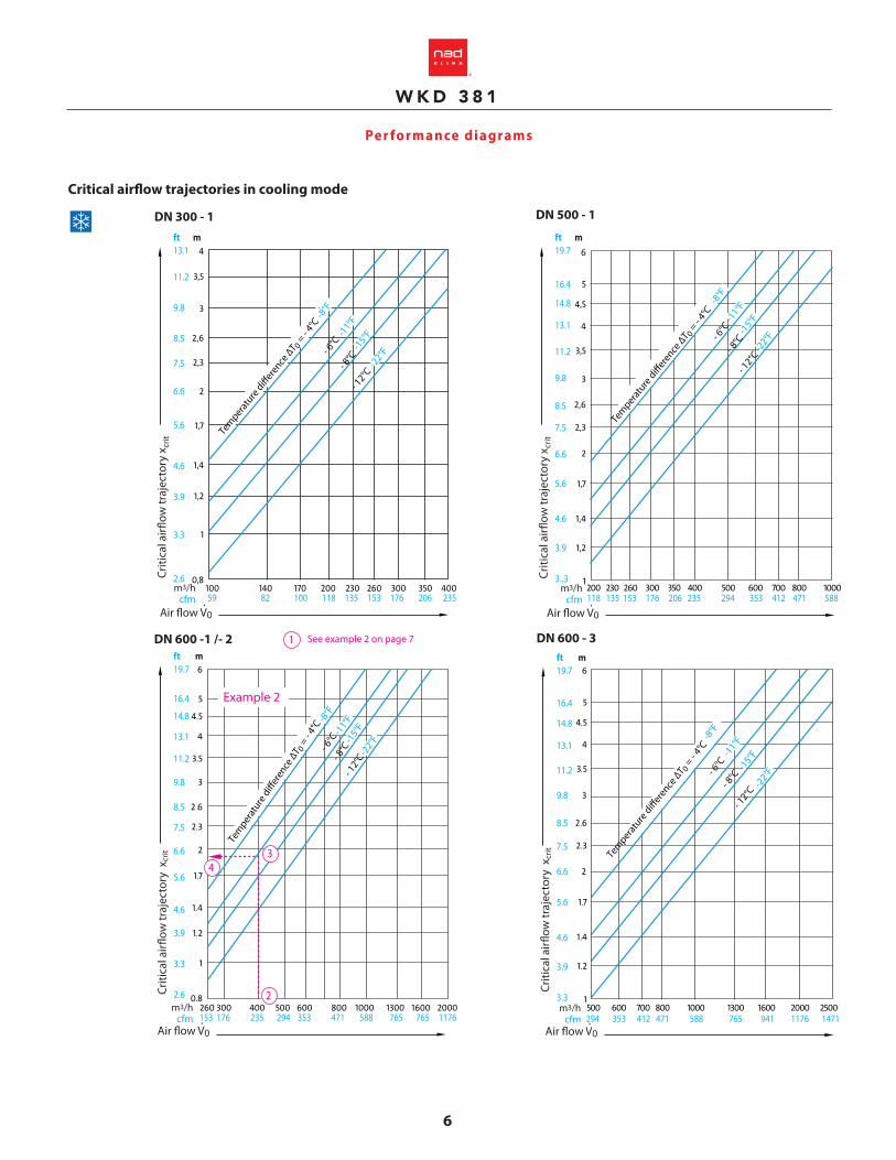
DN 300 - 1 DN 500 - 1
DN 600 -1 /- 2 DN 600 - 3
3
2
4
Example 2
-8°F
-11°F
-15°F
-22°F
m3/hcfm 59 82 100 118 135 153 176 206 235
-8°F
-11°
F-1
5°F
-22°
F
m3/hcfm 153 176 235 294 353 471 588 765 765 1176
-8°F
-11°F
-15°F
-22°F
m3/hcfm 118 135 153 176 206 235 294 353 412 471 588
-8°F
-11°F
-15°F
-22°F
m3/hcfm 294 353 412 471 588 765 941 1176 1471
ft m13.1
11.2
9.8
8.5
7.5
6.6
5.6
4.6
3.9
3.3
2.6
ft m19.7
16.4
14.8
13.1
11.2
9.8
8.5
7.5
6.6
5.6
4.6
3.9
3.,3
ft m19.7
16.4
14.8
13.1
11.2
9.8
8.5
7.5
6.6
5.6
4.6
3.9
3.3
2.6
ft m19.7
16.4
14.8
13.1
11.2
9.8
8.5
7.5
6.6
5.6
4.6
3.9
3.3
.
.
.
.
.
.
.
.
.
.
.
.
.
.
.
Tempera
ture
di�ere
nce ∆T 0 =
- 4°C
- 6°C
- 8°C
- 12°C
Criti
cal a
ir�ow
traj
ecto
ry x
crit
Criti
cal a
ir�ow
traj
ecto
ry x
crit
Air �ow V0 .
Tempera
ture
di�ere
nce ∆T 0 =
- 4°C
- 6°C
- 8°C
- 12°C
Tempera
ture
di�ere
nce ∆T 0 =
- 4°C
- 6°C
- 8°C
- 12°C
Tem
perat
ure d
i�er
ence
∆T 0
= - 4°C
- 6°C
- 8°C
- 12°
C
1 See example 2 on page 7
Air �ow V0 .
Air �ow V0 .
Air �ow V0 .
Criti
cal a
ir�ow
traj
ecto
ry x
crit
Criti
cal a
ir�ow
traj
ecto
ry x
crit
Critical air�ow trajectories in cooling mode

W K D 3 8 1®
7
Per formance diagrams
Vertical penetration in heating mode
Example 2Data Nominal size: DN 600 - 1Air �ow: 400 m3/hTemperature di�erence: - 6°C
RequiredCritical air �ow trajectory
SolutionFrom the critical air �ow trajectory we see:xcrit = 1.9 m
Example 3Data Air �ow: 600 m3/hTemperature di�erence: +10°C
Research1. Dimension of the di�user2. Vertical penetration depth in heating mode3. Acoustic power LWA and the total loss of pressure
Solution1. From the “Areas of application” diagram we
read the dimension DN 600 – 12. From the “Vertical penetration in heating
mode” diagram we follow y = 5.5 m3. From the “Horizontal air �ow” diagram we
follow: acoustic power = 48 dB(A) Total loss of pressure = 115 Pa
Note: If there is no modulation and the air is
100% vertical and isothermal to y = 5.5 we read VMAX: 0.48 m/s.
Example 1Data Height of the space: 3 m (10 ft)Maximum speed of the air�ow at head height (1.8m): 0.15 m/sAir�ow Vo: 400 m3/hRequired1. Dimension of the di�user2. Acoustic power LWA, loss of pressure, distance between the di�users.
Solution 1)From the “Areas of application” diagram we read the nominal dimension DN 500 / 1.2)From the “Horizontal air �ow” diagram we follow the DN 500 -1 and for an air�ow of 400m3/h: a. Acoustic power: 60 dB(A) b. Total loss of pressure: 50 Pa c. For y = h – 1.8 = 3.0 m – 1.8 m = 1.2 m
We deduce for v=0.15 m/s a distance between di�users of at least 2 x 1.5m = 3 m.
.5
12
2
1
4
56
78
33
4
1
23
46
57
5°C
Tem
perat
ure d
i�er
ence
∆T 0
= 10°
C15
°C
20°C
30
°C
DN 300-1 DN 500-1 DN 600-1/-2/-3
Vert
ical
pen
etra
tion
dept
h y
max
5°C
Tempera
ture
di�ere
nce ∆T 0 =
10°C
15°C
20°C
30°C
5°C
Temperature di�erence ∆T0 =
10°C
15°C
20°C
30°C
2
34
Air �ow V0 .
9°F
18°F27°F
36°F54°F
9°F18°F
27°F
36°F
54°F
9°F 18°F
27°F
36°F
54°F
m3/hcfm
100 120 130 140 200 230 250 300 350 400 200 230 250 300 350 400 500 600 700 800 1000 250 300 400 500 600 700 1000 1400 1800 2000 59 71 76 82 118 135 147 176 206 235
Air �ow V0 .
m3/hcfm 118 135 147 176 206 235 294 353 412 471 588
Air �ow V0 .
m3/hcfm 147 176 235 294 353 412 588 824 1059 1176
m
1098
7
65.5
54,5
4
3,5
3
2,6
2,3
2
1,7
1,4
ft.
3329,526,2
23
19,718
16,414,813,1
11,5
9,8
8,5
7,5
6,6
5,6
4,6Vert
ical
pen
etra
tion
dept
h y
max
m
1098
7
6
54.5
4
3.5
3
2.6
2.3
2
1.7
1.4
ft.
3329.526.2
23
19.7
16.414.813.1
11.5
9.8
8.5
7.5
6.6
5.6
4.6Vert
ical
pen
etra
tion
dept
h y
max
m
10
9
8
7
6
5
4.5
4
3.5
3
2.6
ft
33
29.5
26.2
23
19.7
16.4
14.8
13.1
11.5
9.8
8.5

W K D 3 8 1®
8
Temp erature and induc tion b ehavior
D imensions
V̇ XY /
V̇
∆T X
Y /
∆T 0
3.3 3.9 4.6 5.6 6.6 7.5 8.5 9.8 11.5 13.1 14.8 16.4 19.7 23 26.2 29.5 32.8mft
.
.
.
.
.
.
.
.
.
.
.
.
.
.
.
.........
� A
C
ØD
50
ØA
300/1
500/1
600/1
600/2
600/3
300
502
603
603
603
403
403
403
503
603
150
200
250
350
400
133
186
133
134
186
.
� A ØA
BCØD
50
B C Ø D �A/ØA DN
Length of the air�ow direction x ou x+y
Displacement �ow
Axial - Radial Flow
Temperature behavior and the nozzle position’s in�uence on the jet
WKD 381, plenum with top inlet
WKD 381, plenum with side inlet

W K D 3 8 1®
9
Sp eci�c ations
Co di�c ation
1- Description and physical characteristics
1.1 The swirl air di�user shall be made of steel. The square or round di�user shall be equipped with an ajustable nozzle to guide the air �ow.
1.2 The di�user shall be equipped with a turbulence cham-ber composed of a round plate with vertically placed eccentric rollers.
1.3 The di�user adjustment mechanism shall be available in manual and motorized modes.
1.4 The di�user shall be powder coated with a polyester TGIC-free paint, providing a smooth, easy-to-clean, chip and fade resistant �nish. The architect or client shall choose a standard colour from the RAL colour chart.
2 - Performance
The performance shall be guaranted by using performance curves or simulation software for critical areas. These curve shall indicate the pressure drop, acoustic power generated as well as showing a cross-sectional view illustrating the critical air�ow path in cooling, isothermal and heating modes. This critical air�ow path shall have a rated speed at 1.8 m (6 ft) from the ground in occupied area or as requested by the engineer.
3 - Installation
The swirl di�user shall be mounted on a galvanized steel plenum supplied by the manufacturer.
4 - Balancing
4.1 The di�user balancing shall be executed by a ventilation system balancing technician holding a certi�cate of quali�cation.
5 - Quality Requirements: NAD Klima, model WKD 381
WKD 381 Product
ExempleWKD381 - Q - 300 - 300 - 1 - 9003 - T - H
300, 500, 600
300, 502, 603, RND
Nominal dimension
Outer size
Con�guration
Di�user color
Adjustment
Slot height
Plenum
H = Hand adjustmentM = Motorized adjustment
1 = 100 mm2 = 200 mm3 = 300 mm
(DN 600 only)(DN 600 only)
T = Plenum with top inlet S = Plenum with side inlet
9003 = White9010 = Cream00SB = Solar Black (Standard matte black)00SM = Silver Matte (Standard metallic grey)____ = RAL color (write the RAL color number)
Q = Square R = Round
(DN 600 only)

L i s t o f s y m b o l s a n d b a s i c c o n c e p t®
NAD Klima144, rue Léger,
Sherbrooke, QC, J1L 1L9 CanadaT : 819 780-0111 • 1 866 531-1739
F : 819 [email protected]
NAD Klima Ontario 2840, Argentia Road, Unit 6,
Mississauga, ON, L5N 8G4 CanadaT : 416-860-1067
D A L 3 5 8®
®
www.nadklima.com
MADE IN
Recommended