
Wiring Systems and Fault Finding
For Installation Electricians
17th Edition
IET Wiring Regulations:
Wiring Systems and Fault Finding
For Installation Electricians
Fifth Edition
Brian Scaddan, IEng, MIET

Fifth Edition published 2012by Routledge2 Park Square, Milton Park, Abingdon, Oxon OX14 4RN
Simultaneously published in the USA and Canadaby Routledge711 Third Avenue, New York, NY 10017
Routledge is an imprint of the Taylor & Francis Group, an informa business
© 2012 Brian Scaddan
The right of Brian Scaddan to be identified as author of this work has been asserted by him in accordance with sections 77 and 78 of the Copyright, Designs and Patents Act 1988.
All rights reserved. No part of this book may be reprinted or reproduced or utilised in any form or by any electronic, mechanical, or other means, now known or hereafter invented, including photocopying and recording, or in any information storage or retrieval system, without permission in writing from the publishers.
Trademark notice: Product or corporate names may be trademarks or registered trademarks, and are used only for identification and explanation without intent to infringe.
First edition published 1991 by Newnes, an imprint of ElsevierFourth edition published 2008 by Elsevier
British Library Cataloguing in Publication DataA catalogue record for this book is available from the British Library
Library of Congress Cataloging in Publication DataA catalog record for this title has been requested
ISBN: 978-0-415-52210-6 (pbk)ISBN: 978-0-203-11988-4 (ebk)
Typeset in Kuenst480 BT by RefineCatch Limited, Bungay, Suffolk
v
Contents
PREFACE ....................................................................................................... vii
CHAPTER 1 Diagrams ............................................................................... 1
BS EN 60617 Symbols .................................................................................... 1
Diagrams ................................................................................... ....................5
Circuit Convention .................................................................................... .......9
Constructing and Interpreting Circuit Diagrams ................................................. 9
Heating and Ventilation System ...................................................................... 12
Relay Logic .................................................................................................. 14
Programmable Logic Controllers ..................................................................... 16
Drawing Exercises ......................................................................................... 21
CHAPTER 2 Wiring Systems ..................................................................... 23
Radial Systems ............................................................................................. 24
Ring Circuits ................................................................................................ 24
Distribution Systems ...................................................................................... 25
Emergency Lighting Systems .......................................................................... 32
Security and Fire Alarm Systems .................................................................... 36
Call Systems ................................................................................................. 40
Motor Starter Circuits ..................................................................................... 40
Central Heating Systems ................................................................................ 43
Extra Low-Voltage Lighting .............................................................................. 48
Domestic Telephone Systems ......................................................................... 49
CHAPTER 3 Testing and Test Instruments ................................................ 53
Measurement of Electrical Quantities .............................................................. 53
Selection of Test Instruments .......................................................................... 54
Approved Test Lamps and Voltage Indicators ................................................... 55
Accidental RCD Operation ............................................................................. 56
Calibration, Zeroing and Care of Instruments ................................................... 56
Continuity of Protective Conductors ................................................................ 57
Continuity of Ring Final Circuit Conductors ..................................................... 60
Insulation Resistance .................................................................................... 65
Polarity ........................................................................................................ 67
Earth Fault Loop Impedance ......................................................................... 69
Earth Electrode Resistance ............................................................................. 74
Contentsvi
Functional Testing ......................................................................................... 79
Prospective Fault Current .............................................................................. 80
CHAPTER 4 Fault Finding ........................................................................ 83
Signs and Symptoms ..................................................................................... 83
Ring and Radial Socket Outlet Circuits ............................................................ 85
Radial Circuits Feeding Fixed Equipment ........................................................ 86
Cable Fault Location ...................................................................................... 87
Emergency Lighting ....................................................................................... 89
Security and Fire Alarm Systems .................................................................... 89
Call Systems ................................................................................................. 90
Central Heating Systems ................................................................................ 91
Motor Starter Circuits .................................................................................... 91
Conclusion and a Cautionary Tale ................................................................... 95
APPENDIX 1 Shock Risk and Safe Isolation .............................................. 97
Electric Shock .............................................................................................. 97
Safe Isolation of Supplies .............................................................................. 102
APPENDIX 2 Basic Electrical Theory ...................................................... 103
Electrical Quantities and Units ..................................................................... 103
Power, Current and Voltage ........................................................................... 106
APPENDIX 3 Solutions ........................................................................... 109
Quiz Controller (Chapter 1) .......................................................................... 109
INDEX ..........................................................................................................111
vii
Preface
The aim of this book is to help the reader to approach the drawing and interpretation of electrical diagrams with confidence, to under- stand the principles of testing and to apply this knowledge to fault finding in electrical circuits.
The abundant colour diagrams with associated comments and expla- nations lead from the basic symbols and simple circuit and wiring dia-grams, through more complex circuitry, to specific types of wiring systems and, finally, to the methodical approach to fault finding.
The new edition has been brought fully in line with the 17th Edition IET Wiring Regulations.
Brian Scaddan
CHAPTER 1
1
Diagrams
Important terms/topics covered in this chapter:
■ BS EN 60617 symbols■ Diagrams■ Circuit convention■ Relay logic
By the end of this chapter the reader should:
■ be aware of the correct symbols to be used on diagrams,■ know the different types of diagrams in general use and why they are
used,■ understand circuit convention and its importance in interpreting
diagrams,■ understand simple relay logic and its application to PLCs.
This is an area often overlooked or even ignored. The IET Wiring Regula-tions require that ‘diagrams, charts, tables or equivalent forms of infor-mation are made available’ to the installer and inspector and tester.
BS EN 60617 SYMBOLS
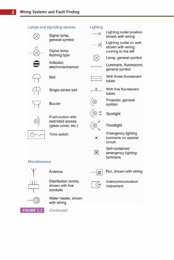
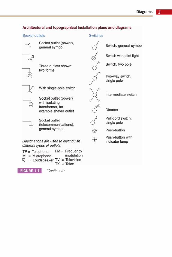
BS EN 60617 gives the graphical symbols that should be used in all electrical/electronic diagrams or drawings. Since the symbols fall in line with the International Electrotechnical Commission (IEC) document 617, it should be possible to interpret non-UK diagrams. Samples of the symbols used in this book are shown in Figure 1.1.
FIGURE 1.1 BS EN 60617 Symbols.
Kind of current and voltage
Direct current
/ \ - * Alternating current
+ Positive polarity
Négative polarity
Mechanical controls Mechanical coupling
Earth and frame connections
■J,
Earth or ground, gênerai symbol
Frame, châssis
Wiring Systems and Fault Finding2
FIGURE 1.1 (Continued)
Lamps and signalhng devices
(Ç*\ Signal lamp, ^ ^ gênerai symbol
J~L _ / 0 \ _ Signal lamp,
flashing type
Indicator, electromechanical
Bell
Single-stroke bell
Buzzer
Push-button with restricted access (glass cover, etc.)
Time switch
Miscellaneous
Y Antenna
Distribution centre, shown with five conduits
Lighting
X
M
Lighting outlet position, shown with wiring
Lighting outlet on wall, shown with wiring running to the left
Lamp, gênerai symbol
Luminaire, fluorescent, gênerai symbol
With three fluorescent tubes
With five fluorescent tubes
Projector, gênerai symbol
Spotlight
Floodlight
Emergency lighting luminaire on spécial circuit
Self-contained emergency lighting luminaire
|oo I Fan, shown with wiring
/
\
-—71 Intercommunication [ x r instrument
Water heater, shown with wiring
Diagrams 3
FIGURE 1.1 (Continued)
Architectural and topographical installation plans and diagrams
Socket outlets Switches
^
$
7,
Socket outlet (power), gênerai symbol
Three outlets shown: two forms
With single-pole switch
Socket outlet (power) with isolating transformer, for example shaver outlet
Socket outlet (télécommunications), gênerai symbol
Désignations are used to distinguish différent types of outlets: TP = Téléphone FM = Frequency M = Microphone modulation m = Loudspeaker TV = Télévision
TX = Télex
Switch, gênerai symbol
Switch with pilot light
Switch, two pôle
Two-way switch, single pôle
Intermediate switch
Dimmer
Pull-cord switch, single pôle
Push-button
Push-button with indicator lamp

Wiring Systems and Fault Finding4
FIGURE 1.1 (Continued)
Switchgear, control gear and protective devices
Contacts
1 ± T
Make contact, normally open: also gênerai symbol for a switch
Break contact
Change-over contact, break before make
Break contact with spring return
Push-button switch (non-locking)
Contactor, normally open: three forms
All-or-nothing relays
*
Coil of a slow-releasing relay
Coil of a slow-operating relay
Coil of a relay unaffected by alternating current
Coil of an alternating current relay
Coil of a mechanically latched relay
Actuating device of a thermal relay
Fuse and fuse switches
Contactor, normally closed: three forms
Fuse, gênerai symbol
Fuse with the supply side indicated
*
s Circuit breaker: two forms
Change-over contact, make before break
Make contact, early to close
Break contact, late to open
Make contact with spring return
Fuse switch
Fuse disconnector
Other forms for contacts and switches Dotted lines dénote alternative switch position
a, 2jl -Y 2 y 3
3 4
t j 3
1 T 2
1 U 4 2Ï""Î3
7 2
~3 X
Diagrams 5
DIAGRAMS
The four most commonly used diagrams are the block diagram, interconnection diagram, the circuit or schematic diagram and the wiring or connection diagram.
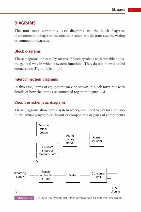
Block diagrams
These diagrams indicate, by means of block symbols with suitable notes, the general way in which a system functions. They do not show detailed connections (Figure 1.2a and b).
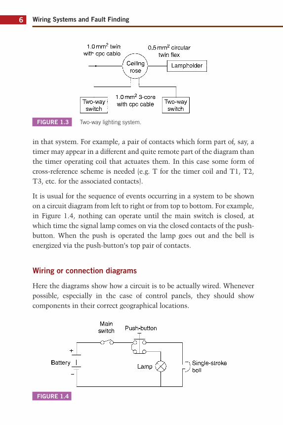
Interconnection diagrams
In this case, items of equipment may be shown in block form but with details of how the items are connected together (Figure 1.3).
Circuit or schematic diagrams
These diagrams show how a system works, and need to pay no attention to the actual geographical layout of components or parts of components
FIGURE 1.2 (a) Security system, (b) Intake arrangement for domestic installation.
Personal attack button
Sensors infrareds
magnetic, etc.
(a)
Supply authority cut-out
Alarm control panel
Alarm sounder
Meter Consumer unit
1 1 ' ' , r y
Final circuits
Wiring Systems and Fault Finding6
in that system. For example, a pair of contacts which form part of, say, a timer may appear in a different and quite remote part of the diagram than the timer operating coil that actuates them. In this case some form of cross-reference scheme is needed (e.g. T for the timer coil and T1, T2, T3, etc. for the associated contacts).
It is usual for the sequence of events occurring in a system to be shown on a circuit diagram from left to right or from top to bottom. For example, in Figure 1.4, nothing can operate until the main switch is closed, at which time the signal lamp comes on via the closed contacts of the push-button. When the push is operated the lamp goes out and the bell is energized via the push-button’s top pair of contacts.
Wiring or connection diagrams
Here the diagrams show how a circuit is to be actually wired. Whenever possible, especially in the case of control panels, they should show components in their correct geographical locations.
FIGURE 1.3 Two-way lighting system.
FIGURE 1.4
1.0 mm2 twin with cpc cable
0.5 mm2 circular twin flex
1.0 mm2 3-core with cpc cable Two-way
switch
Main switch
-or^o-
Push-button
~à
Battery Lamp L n Single-stroke
rUbel l
Diagrams 7
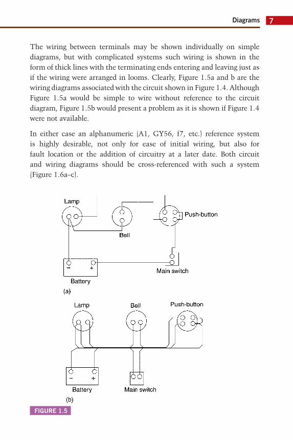
The wiring between terminals may be shown individually on simple diagrams, but with complicated systems such wiring is shown in the form of thick lines with the terminating ends entering and leaving just as if the wiring were arranged in looms. Clearly, Figure 1.5a and b are the wiring diagrams associated with the circuit shown in Figure 1.4. Although Figure 1.5a would be simple to wire without reference to the circuit diagram, Figure 1.5b would present a problem as it is shown if Figure 1.4 were not available.
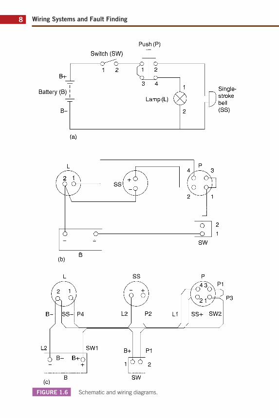
In either case an alphanumeric (A1, GY56, f7, etc.) reference system is highly desirable, not only for ease of initial wiring, but also for fault location or the addition of circuitry at a later date. Both circuit and wiring diagrams should be cross-referenced with such a system (Figure 1.6a–c).
FIGURE 1.5
Lamp
O
o o +
(a) Battery
Lamp
Q Q )
Bell
Bell
/o Push-button
Main switch
Push-button
ZZ.
ô ô + P Ô
Battery Main switch
Wiring Systems and Fault Finding8
FIGURE 1.6 Schematic and wiring diagrams.
Push (P)
B+
Battery (B)
B-
(a)
Switch (SW)
or^b— 1 2
O-2
_o-3 4
Lamp (L)
Single-| ] stroke \J bell
(SS)
SW1
SS
L2 P2
B+
1 Ô Ô
P1
2
SW
S^Z
Diagrams 9
Note how, in Figure 1.6c, each termination is referenced with the destination of the conductor connected to it. Also note how much more easily a circuit diagram makes the interpretation of the circuits function.
CIRCUIT CONVENTION
It is probably sensible at this point to introduce the reader to circuit convention. This is simply a way of ensuring that circuit diagrams are more easily interpreted, and is achieved by drawing such diagrams in a de-energized state known as normal.
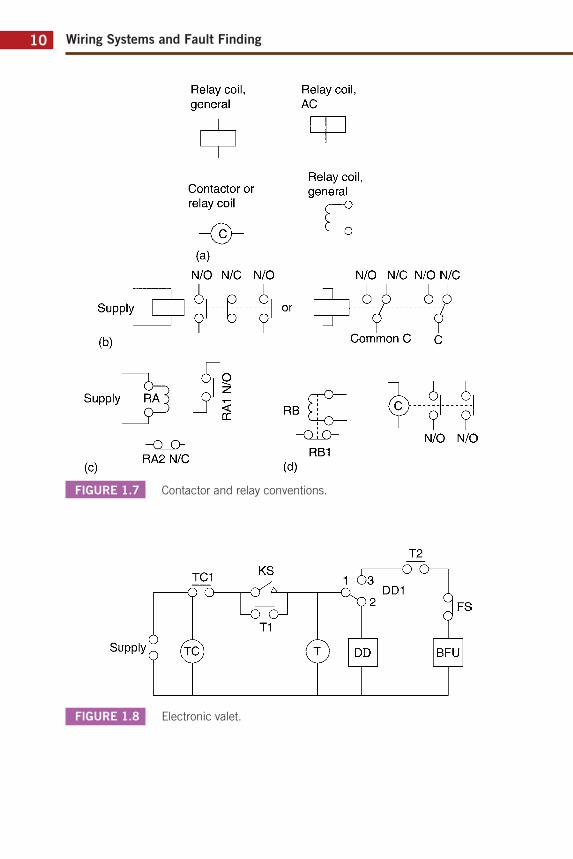
Hence, if we take a new motor starter out of its box, all of the coils, timers, overloads and contacts are said to be in their normal position. Figure 1.7a–d illustrate this convention as applied to relays and contactors.
Note that, provided diagrams follow this accepted convention, it is unnecessary to label contacts normally open (N/O) or normally closed (N/C).
CONSTRUCTING AND INTERPRETING
CIRCUIT DIAGRAMS
In order to construct or interpret a circuit /schematic diagram of the controls of a particular system, it is necessary to understand, in broad principles, how the system functions. A logical approach is needed, and it may take the novice some while before all ‘clicks’ into place.
Here is an example to consider.
Electronic valet
You work hard every day and return home late every evening. When you come in you look forward to a smooth scotch, a sit down and then a relaxing soak in a hot bath. If you were acquainted with electrical control systems you could arrange for these little luxuries to be automated as shown in Figure 1.8.
Wiring Systems and Fault Finding10
FIGURE 1.7 Contactor and relay conventions.
FIGURE 1.8 Electronic valet.
Relay coil, gênerai
Relay coil, AC
Supply
(b)
Contactor or relay coil
Relay coil, gênerai
C (a)
N/O N/C N/O
-, i, i i. J—-----F—i or
<5TS Supply RA^ o ' ,-
N/O N/C N/O N/C
^ i i 3"
Common C
-Q_£> RA2 N/C
- o i o -RB1
(d)
i, i, ?' ?'
N/O N/O
TC1
-o o-KS i 5
T2 -O C
DD1 FS
T1 Supply Ô
O © DD BFU
Diagrams 11
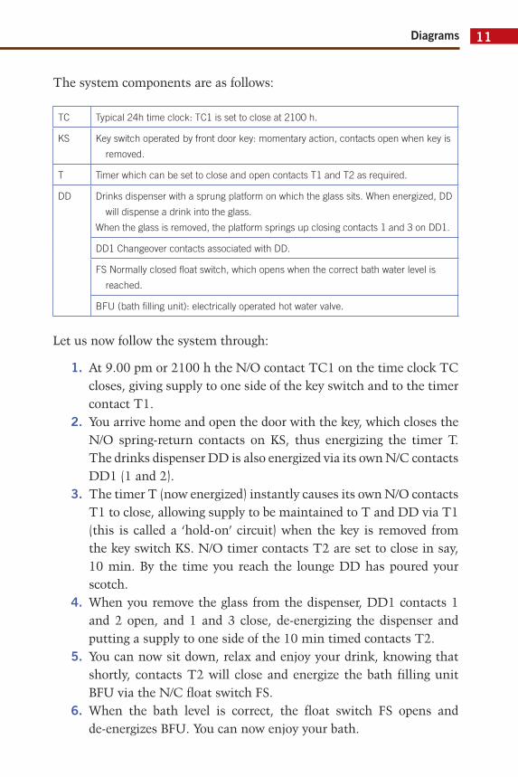
The system components are as follows:
TC Typical 24h time clock: TC1 is set to close at 2100 h.
KS Key switch operated by front door key: momentary action, contacts open when key is
removed.
T Timer which can be set to close and open contacts T1 and T2 as required.
DD Drinks dispenser with a sprung platform on which the glass sits. When energized, DD
will dispense a drink into the glass.
When the glass is removed, the platform springs up closing contacts 1 and 3 on DD1.
DD1 Changeover contacts associated with DD.
FS Normally closed fl oat switch, which opens when the correct bath water level is
reached.
BFU (bath fi lling unit): electrically operated hot water valve.
Let us now follow the system through:
1. At 9.00 pm or 2100 h the N/O contact TC1 on the time clock TC closes, giving supply to one side of the key switch and to the timer contact T1.
2. You arrive home and open the door with the key, which closes the N/O spring-return contacts on KS, thus energizing the timer T. The drinks dispenser DD is also energized via its own N/C contacts DD1 (1 and 2).
3. The timer T (now energized) instantly causes its own N/O contacts T1 to close, allowing supply to be maintained to T and DD via T1 (this is called a ‘hold-on’ circuit) when the key is removed from the key switch KS. N/O timer contacts T2 are set to close in say, 10 min. By the time you reach the lounge DD has poured your scotch.
4. When you remove the glass from the dispenser, DD1 contacts 1 and 2 open, and 1 and 3 close, de-energizing the dispenser and putting a supply to one side of the 10 min timed contacts T2.
5. You can now sit down, relax and enjoy your drink, knowing that shortly, contacts T2 will close and energize the bath filling unit BFU via the N/C float switch FS.
6. When the bath level is correct, the float switch FS opens and de-energizes BFU. You can now enjoy your bath.
Wiring Systems and Fault Finding12
7. One hour, say, after arriving home, the timer T will have completed its full cycle and reset, opening T1 and T2 and thus restoring the whole system to normal.
This system is, of course, very crude. It will work but needs some refinement. What if you arrive home early – surely you need not stay dirty and thirsty? How do you take a bath during the day without using the door key and having a drink? What about the bath water temperature? And so on. If you have already begun to think along these lines and can come up with simple solutions, then circuit/schematic diagrams should present no real problems to you.
Quiz controller
Here is another system to consider. Can you draw a circuit/schematic diagram for it? (A solution is given at the end of the book.)
The system function is as follows:
1. Three contestants take part in a quiz show. Each has a push-to-make button and an indicator lamp.
2. The quizmaster has a reset button that returns the system to normal.
3. When a contestant pushes his/her button, the corresponding lamp is lit and stays lit. The other contestants’ lamps will not light.
4. The items of equipment are: a source of supply; a reset button (push-to-break); three push-to-make buttons; three relays each with 1 N/O and 2 N/C contacts and three signal lamps.
The resulting diagram is a good illustration of the use of an alpha-numeric system to show relay coils remote from their associated contacts.
HEATING AND VENTILATION SYSTEM
Figure 1.9 is part of a much larger schematic of the controls for the heating and ventilation system in a large hotel.
From the diagram it is relatively simple to trace the series of events that occur in this section of the system.

Diagrams 13
FIG
UR
E 1
.9
Heating a
nd v
entila
tion s
chem
atic d
iagra
m.
Out
side
de
tect
or
D3
Act
uato
r M
B va
lve
MV
1
Var
iabl
e te
mpé
ratu
re
circ
uit
cont
rols
To
rem
ote
indi
catio
n pa
nel
(by
othe
rs)
N:1
Bo
iter
N:1
N:
1 W
•
M
Var
iabl
e te
mpé
ratu
re
pum
ps
N:1
0.37
DJ-F
Wiring Systems and Fault Finding14
Clearly, there are four pumps: two boiler pumps and two variable temperature pumps. One of each of these pairs is a standby in the event of failure of the other; this will become clear as we interpret the scheme.
There is a controller (similar to the programmer of a central heating system) which receives inputs from two temperature sensors and operates an actuator valve and a time switch. There are two sets of linked, three-position switches and direct-on-line three-phase starters with single-phase coils S1/4, S2/4, S3/4 and S4/4 for the pumps. There is also run and trip indication for each pump.
Let us now follow the sequence of events:
1. The selector switches are set to, say, position 1.2. The temperature sensors operate and the controller actuates valve
MV1. If the 24 V time switch relay R8/2 is energized, then its N/O contacts R8/2 are closed, giving supply to the selector switches.
3. Starters S1/4 and S3/4 are energized via their respective overload (O/L) contacts; the main contacts close and the pumps start. Auxiliary contacts on the starters energize the run lamps.
4. If pump 1, say, were to overload, then the N/O O/L contacts would close, de-energizing S1/4 and shutting down pump 1, and supply would be transferred to starter S2/4 for pump 2 via the second linked switch. At the same time the trip lamp would come on and a supply via a diode and control cable C would be given to relay R9/1, operating its N/O contacts R9/1 to indicate a pump failure at a remote panel. The diode prevents back feeds to other trip lamps via the control cable C from other circuits.
5. The reader will see that the same sequence of events would take place if the selector switch were in position 2 in the first place.
RELAY LOGIC
In the last few pages we have investigated the use of relays for control purposes. Whilst this is perfectly acceptable for small applications, their use in more complex systems is now being superseded by programmable logic controllers (PLCs). However, before we discuss these in more detail, it is probably best to begin with a look at relay logic.
Diagrams 15
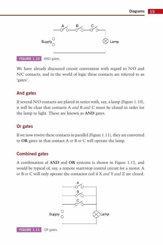
We have already discussed circuit convention with regard to N/O and N/C contacts, and in the world of logic these contacts are referred to as ‘gates’.
And gates
If several N/O contacts are placed in series with, say, a lamp (Figure 1.10), it will be clear that contacts A and B and C must be closed in order for the lamp to light. These are known as AND gates.
Or gates
If we now rewire these contacts in parallel (Figure 1.11), they are converted to OR gates in that contact A or B or C will operate the lamp.
Combined gates
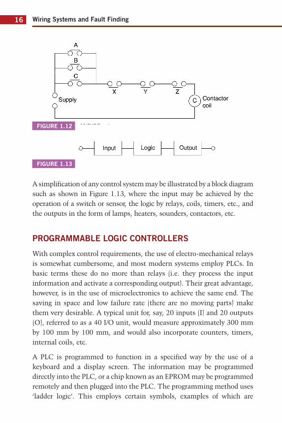
A combination of AND and OR systems is shown in Figure 1.12, and would be typical of, say, a remote start/stop control circuit for a motor. A or B or C will only operate the contactor coil if X and Y and Z are closed.
FIGURE 1.10 AND gates.
FIGURE 1.11 OR gates.
<JO C^O C^O-
Supply (X) Lamp
-cro-
-cro-Supply ( X ) Lamp
Wiring Systems and Fault Finding16
A simplification of any control system may be illustrated by a block diagram such as shown in Figure 1.13, where the input may be achieved by the operation of a switch or sensor, the logic by relays, coils, timers, etc., and the outputs in the form of lamps, heaters, sounders, contactors, etc.
PROGRAMMABLE LOGIC CONTROLLERS
With complex control requirements, the use of electro-mechanical relays is somewhat cumbersome, and most modern systems employ PLCs. In basic terms these do no more than relays (i.e. they process the input information and activate a corresponding output). Their great advantage, however, is in the use of microelectronics to achieve the same end. The saving in space and low failure rate (there are no moving parts) make them very desirable. A typical unit for, say, 20 inputs (I) and 20 outputs (O), referred to as a 40 I/O unit, would measure approximately 300 mm by 100 mm by 100 mm, and would also incorporate counters, timers, internal coils, etc.
A PLC is programmed to function in a specified way by the use of a keyboard and a display screen. The information may be programmed directly into the PLC, or a chip known as an EPROM may be programmed remotely and then plugged into the PLC. The programming method uses ‘ladder logic’. This employs certain symbols, examples of which are
FIGURE 1.12 AND/OR gates.
FIGURE 1.13
A
B -O O
c -o o
Supply
-o_o-X
-Q_o Y
- Q j z
(Q\ Contactor
o- Input Logic Output
Diagrams 17
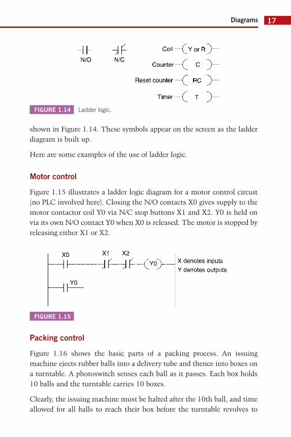
shown in Figure 1.14. These symbols appear on the screen as the ladder diagram is built up.
Here are some examples of the use of ladder logic.
Motor control
Figure 1.15 illustrates a ladder logic diagram for a motor control circuit (no PLC involved here). Closing the N/O contacts X0 gives supply to the motor contactor coil Y0 via N/C stop buttons X1 and X2. Y0 is held on via its own N/O contact Y0 when X0 is released. The motor is stopped by releasing either X1 or X2.
FIGURE 1.14 Ladder logic.
FIGURE 1.15
Packing control
Figure 1.16 shows the basic parts of a packing process. An issuing machine ejects rubber balls into a delivery tube and thence into boxes on a turntable. A photoswitch senses each ball as it passes. Each box holds 10 balls and the turntable carries 10 boxes.
Clearly, the issuing machine must be halted after the 10th ball, and time allowed for all balls to reach their box before the turntable revolves to
Hh N/0
^ N/C
Coil — ( j f or R
Counter—(^ C
Reset counter —C RC
Timer — ( T
xo X1 X2 <vo>
YO
X dénotes inputs Y dénotes outputs
Wiring Systems and Fault Finding18
bring another box into place. When the 10th box has been filled, the system must halt and a warning light must be energized to indicate that the process for that batch is completed. When new boxes are in place the system is restarted by operating an N/C manual reset button.
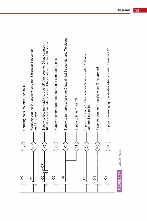
This system is ideal for control by a PLC with its integral counters and timers. Figure 1.17 shows an example of the ladder logic for this system using the following:
X0 N/O photocell switch: closes as ball passes.
X1 N/C manual reset button.
Y0 Output supply to issuing machine.
Y1 Output supply to turntable.
Y2 Output supply to warning light.
C0 Internal counter set to 10 with one N/C and two N/O contacts.
C1 Internal counter set to 10 with one N/C and one N/O contacts.
T0 Timer set for 5 s with one N/O contact.
T1 Timer set for 5 s with one N/C contact.
RC Reset counter: resets counter when supply to it is cut.
FIGURE 1.16
^
Turntable
Diagrams 19
FIG
UR
E 1
.17
Ladder
logic
.
xo
<co>
if T1
CO
,/C
1 ^
f CO
TO
CO
i\ X1
C1
<R
C>
<Y
O>
<T
O>
<Y
1>
<T
1>
<C
1>
<R
C>
<Y
2>
Cou
ntin
g ba
lls: c
ount
er O
set
to 1
0
Res
et fo
r cou
nter
0: r
eset
s w
hen
timer
1 e
laps
es 5
sec
onds
, an
d T1
ope
ns
Supp
ly to
issu
ing
mac
hine
: cut
s of
f afte
r co
unte
r 0
has
coun
ted
10 b
alls
and
aga
in a
fter
coun
ter
1 ha
s in
effe
ct c
ount
ed 1
0 bo
xes
Supp
ly to
tim
er 0
afte
r cou
nter
0 h
as c
ount
ed 1
0 ba
lls
Supp
ly to
turn
tabl
e af
ter t
imer
0 h
as ti
med
5 s
econ
ds, a
nd T
0 cl
oses
Supp
ly to
tim
er 1
via
T0
Supp
ly to
cou
nter
1 a
fter c
ount
er 0
has
cou
nted
10
balls
: co
unte
r 1
setto
10
Res
et fo
r cou
nter
1 :
rese
ts w
hen
X1 is
ope
ned
Supp
ly to
war
ning
ligh
t: op
érât
es w
hen
coun
ter
1 re
ache
s 10
Wiring Systems and Fault Finding20
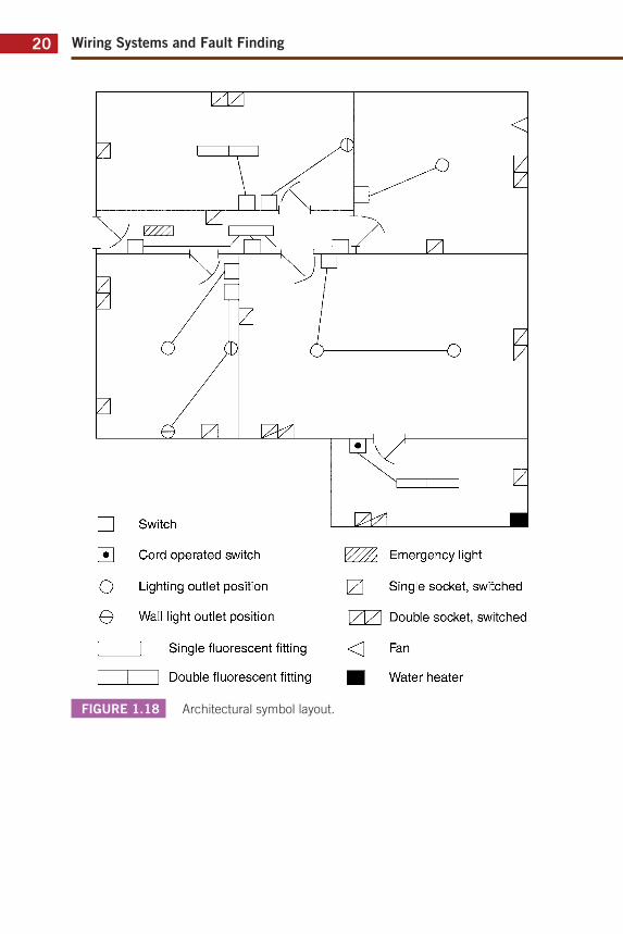
FIGURE 1.18 Architectural symbol layout.
Switch
Cord operated switch
Lighting outlet position
Wall light outlet position
~2 Single fluorescent fitting
| Double fluorescent fitting
Emergency light
171 Single socket, switched
1/1/1 Double socket, switched
< Fan
■ Water heater
Diagrams 21
Fault location
Another major advantage of the use of PLCs for controlling systems is the relative ease of fault location. In the event of system failure, the keyboard and screen unit is plugged into the PLC and the condition of the system is displayed in ladder logic on the screen. Then, for example, any contact that is in the wrong position will show up.
DRAWING EXERCISES
1. Using BS EN 60617 architectural symbols, draw block diagrams of the following circuits:(a) A lighting circuit controlled by one switch, protected by a fuse,
and comprising three tungsten filament lamp points, two double fluorescent luminaires, and one single fluorescent luminaire.
(b) A lighting circuit controlled by two-way switches, protected by a fuse, and comprising three floodlights.
(c) A lighting circuit controlled by two-way switches, and one intermediate switch, protected by a circuit breaker, and com-prising three spotlights. One of the two-way switches is to be cord operated.
(d) A ring final circuit protected by a circuit breaker, and comprising six double switched socket outlets and two single switched socket outlets.
2. Replace the symbols shown in Figure 1.18 with the correct BS EN 60617 symbols.
Solutions are given at the end of the book.
23
CHAPTER 2
Wiring Systems
Important terms/topics covered in this chapter:
■ BS 7671 conductor identification■ Ring, radial and distribution circuits and systems■ Emergency lighting, alarm and security systems■ Call systems ■ Motor starting systems■ Central heating systems■ Extra low voltage systems■ Domestic telephone systems
By the end of this chapter the reader should:
■ be aware of the various wiring systems i.e. ring, radial and distribution,
■ understand the need for installation diagrams to have a circuit identification system,
■ understand ‘open’ and ‘closed’ wiring systems,■ know that knowledge of how a system functions helps the
interpretation of diagrams.
In this chapter we will investigate a selection of the many wiring systems employed in modern installations. Some of these systems are simple to understand and require little explanation. Others of a more complex nature should now, in the light of the reader’s new-found knowledge of diagrams, etc., present only minor problems of inter-pretation.
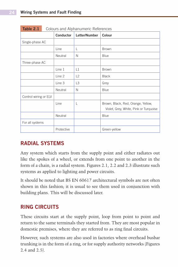
It should be noted that diagrams for LV systems rarely indicate conductor colours, it is more likely that control circuit and ELV system diagrams will show these. Table 2.1 shows the colours/alphanumeric references required by the IET Wiring Regulations.
Wiring Systems and Fault Finding24
Table 2.1 Colours and Alphanumeric References
Conductor Letter/Number Colour
Single-phase AC
Line L Brown
Neutral N Blue
Three-phase AC
Line 1 L1 Brown
Line 2 L2 Black
Line 3 L3 Grey
Neutral N Blue
Control wiring or ELV
Line L Brown, Black, Red, Orange, Yellow,
Violet, Grey, White, Pink or Turquoise
Neutral Blue
For all systems
Protective Green-yellow
RADIAL SYSTEMS
Any system which starts from the supply point and either radiates out like the spokes of a wheel, or extends from one point to another in the form of a chain, is a radial system. Figures 2.1, 2.2 and 2.3 illustrate such systems as applied to lighting and power circuits.
It should be noted that BS EN 60617 architectural symbols are not often shown in this fashion; it is usual to see them used in conjunction with building plans. This will be discussed later.
RING CIRCUITS
These circuits start at the supply point, loop from point to point and return to the same terminals they started from. They are most popular in domestic premises, where they are referred to as ring final circuits.
However, such systems are also used in factories where overhead busbar trunking is in the form of a ring, or for supply authority networks (Figures 2.4 and 2.5).
Wiring Systems 25
FIGURE 2.1 Radial lighting circuit using (a) representative, (b) architectural
symbols.
FIGURE 2.2 Radial socket outlet circuit using (a) representative, (b) architectural
symbols.
DISTRIBUTION SYSTEMS
Such systems are many and varied, but they are quite simple to understand as they tend to follow the ring and radial concepts.
Take, for example, the UK electricity system. Regardless of who owns this or that part of it, the system functions in the following stages: generation, transmission and distribution. Generated electricity is transmitted over vast distances around the United Kingdom in a combination of ring and radial circuits to points of utilization, where it is purchased by the distribution network operators (DNOs) and distributed to their customers. Once again these systems are in ring or radial forms.
Protection Supply o 1 |—
(a)
H I I
(b)
S/O
Je Je Jr
Light point Protection LP
Supply
(a) One-way switch
D ^ 3 - -¥- -¥-
(b) ir ir ir
Wiring Systems and Fault Finding26
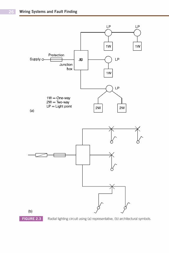
FIGURE 2.3 Radial lighting circuit using (a) representative, (b) architectural symbols.
Protection Supply o 1 |
Junction box
1W = One-way 2W = "Iwo-way LP = Light point
H = h
^
■ * ■
Wiring Systems 27
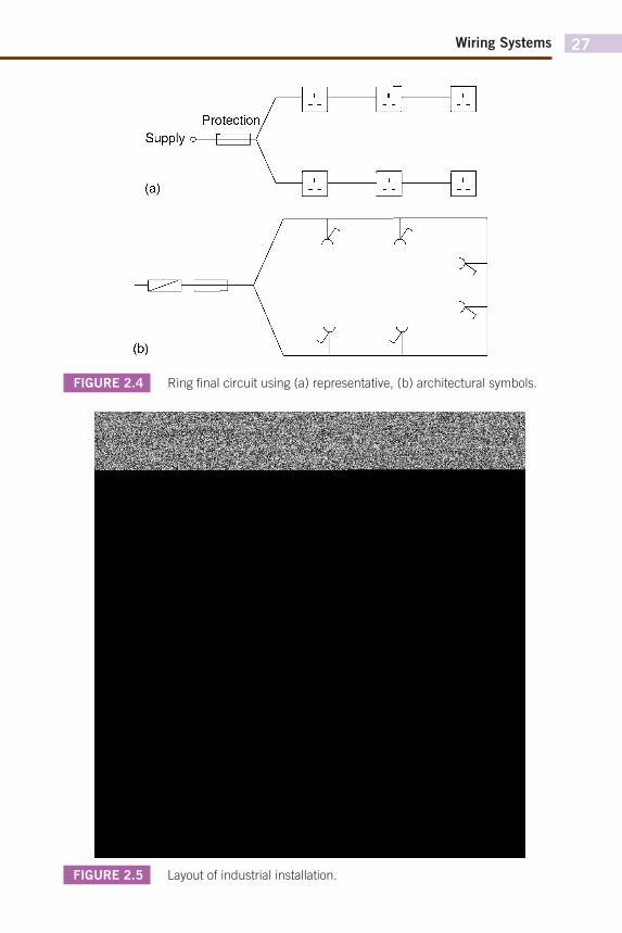
FIGURE 2.4 Ring fi nal circuit using (a) representative, (b) architectural symbols.
FIGURE 2.5 Layout of industrial installation.
Protection/ Supply o—| | ■
(a)
y y-E
(b) 1 1 Machine
Machine
MachineH
Machine
Machine
Machine Machine I Machine-
L I — r
L3-N -
SF BB
L1 L2 L3
L1 L2 L3
Main switch-fuse
or circuit breaker
Busbar chamber
Machine
Machine
Machine
SF
Machine TP&N switch-fuse
Overhead tap-off busbar trunking (ring main) feeding single- and three-phase motors
SF BB
L1
N L2
DB
N L3
DB
TP&N switch-
fuse
Busbar chamber
DB
A Heating, lighting and power final subcircuits balanced over three phases
Sub-main cables
(usually PVC armoured)
\ J Distribution
boards
Wiring Systems and Fault Finding28
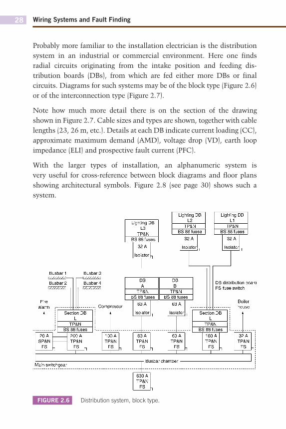
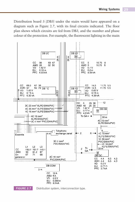
Probably more familiar to the installation electrician is the distribution system in an industrial or commercial environment. Here one finds radial circuits originating from the intake position and feeding dis-tribution boards (DBs), from which are fed either more DBs or final circuits. Diagrams for such systems may be of the block type (Figure 2.6) or of the interconnection type (Figure 2.7).
Note how much more detail there is on the section of the drawing shown in Figure 2.7. Cable sizes and types are shown, together with cable lengths (23, 26 m, etc.). Details at each DB indicate current loading (CC), approximate maximum demand (AMD), voltage drop (VD), earth loop impedance (ELI) and prospective fault current (PFC).
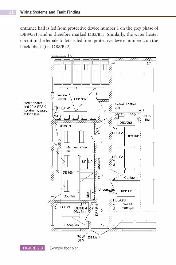
With the larger types of installation, an alphanumeric system is very useful for cross-reference between block diagrams and floor plans showing architectural symbols. Figure 2.8 (see page 30) shows such a system.
FIGURE 2.6 Distribution system, block type.
Busbar1 Y//////A Busbar 2 Y//////A—i
Fire alarm
20 A SP&N
FS X
Busbar 3 Y//////A Busbar 4
I—Y//////A
Section DB L
TP&N BS 88 fuses
200 A TP&N
FS X
Compressor
100 A TP&N
FS X
Lighting DB L3
TP&N BS 88 fuses
32 A
Isolator
DB A
TP&N BS 88 fuses
63 A
Isolator
63 A TP&N
FS
X
Lighting DB L2
TP&N BS 88 fuses
32 A
Isolator
Lighting DB L1
TP&N BS 88 fuses
32 A
Isolator
DB B
TP&N BS 88 fuses
63 A
Isolator
63 A TP&N
FS
X
DB distribution board FS fuse switch
Boiler house
Section DB L
TP&N BS 88 fuses
100 A TP&N
FS
X
32 A TP&N
FS
X
Main switchgear Busbar chamber -
Wiring Systems 29
Distribution board 3 (DB3) under the stairs would have appeared on a diagram such as Figure 2.7, with its final circuits indicated. The floor plan shows which circuits are fed from DB3, and the number and phase colour of the protection. For example, the fluorescent lighting in the main
FIGURE 2.7 Distribution system, interconnection type.
DB2C
ce AMD VD ELI PFC
69.5 52 i 1.43 V 0.15n 6.32 kA
CC 38 69 67 AMD 28 52 50 VD 1.62 V ELI 0.16 n PFC 6.03 kA
67 38 50 29 DB1C
DB2D
DSDP
ce AMD VD ELI PFC
5 5 0.7 V 0.2 n 4.09 kA
10.75 10.75
DB1D (MlÛ
CC 14.5 AMD 14.5 VD 0.83 V ELI 0.19 n PFC 4.39 kA
11.75 11.75
5.5 5.5
3C 23 mm2 XLPE/SWA/PVC -4C 35 mm2 XLPE/SWA/PVC" 4C 16 mm2 XLPE/SWA/PVC"
- 4 C 1 6 m m 2
XLPE/SWA/PVC -3C 4 mm2 PVC/SWA/PVC
CC 5 29 38 AMD 40 25 35 VD 1.92 V ELI 0.17 n
-12
PFC 4^8 kA | ToGÀ^-i
m DBGB
30 m 4C 25 mm2
XLPE/SWA/PVC
m Essential
L1 CC 150.2 AMD 90
|On 67 generator
L2 152.7 91.2 71
L3 145.1 87 68
r n Téléphone 4 m| exchange panel
4_
3C 4 mm2
PVC/SWA/PVC
3C16mm 2
PVC/SWA/PVC
-i-To GA~
4C 70 mm2
XLPE/SWA/PVC 1C35mm 2
PVC/SWA/PVC «— 4C16mm 2
XLPE/SWA/PVC 30 m
-m DBGC
3 m
DBCOM
CC AMD VD ELI PFC
4.4 4.4 0.5 V 0.21 n 3.7 kA
6.5 6.5
4.3 4.3
CC 12A AMD 6 A VD 0.5 V ELI 0.093 n PFC 8.5 kA
Wiring Systems and Fault Finding30
entrance hall is fed from protective device number 1 on the grey phase of DB3/Gr1, and is therefore marked DB3/Br1. Similarly, the water heater circuit in the female toilets is fed from protective device number 2 on the black phase (i.e. DB3/Bk2).
FIGURE 2.8 Example fl oor plan.
Water heater and30ASP&N isolator mounted at high level
70 W DB3/Gr4 50 N
Wiring Systems 31
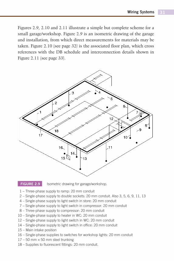
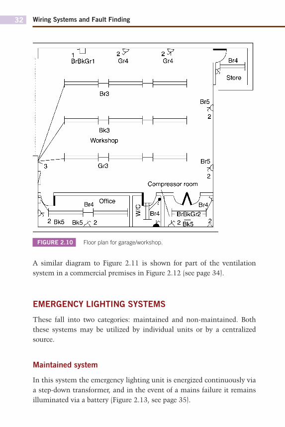
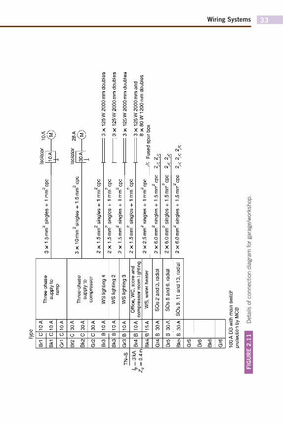
Figures 2.9, 2.10 and 2.11 illustrate a simple but complete scheme for a small garage/workshop. Figure 2.9 is an isometric drawing of the garage and installation, from which direct measurements for materials may be taken. Figure 2.10 (see page 32) is the associated floor plan, which cross references with the DB schedule and interconnection details shown in Figure 2.11 (see page 33).
FIGURE 2.9 Isometric drawing for garage/workshop.
1 – Three-phase supply to ramp: 20 mm conduit
2 – Single-phase supply to double sockets: 20 mm conduit. Also 3, 5, 6, 9, 11, 13
4 – Single-phase supply to light switch in store: 20 mm conduit
7 – Single-phase supply to light switch in compressor: 20 mm conduit
8 – Three-phase supply to compressor: 20 mm conduit
10 – Single-phase supply to heater in WC: 20 mm conduit
12 – Single-phase supply to light switch in WC: 20 mm conduit
14 – Single-phase supply to light switch in offi ce: 20 mm conduit
15 – Main intake position
16 – Single-phase supplies to switches for workshop lights: 20 mm conduit
17 – 50 mm × 50 mm steel trunking
18 – Supplies to fl uorescent fi ttings: 20 mm conduit.
17
Wiring Systems and Fault Finding32
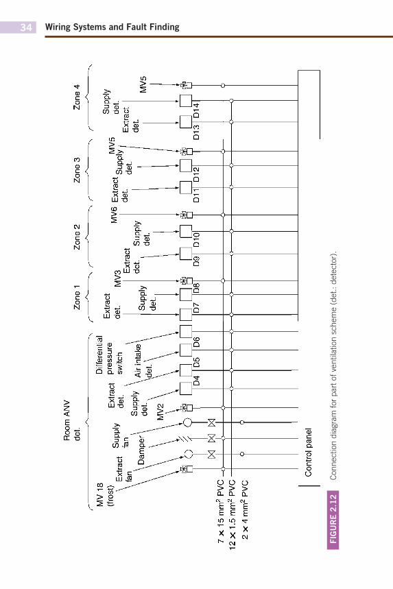
A similar diagram to Figure 2.11 is shown for part of the ventilation system in a commercial premises in Figure 2.12 (see page 34).
EMERGENCY LIGHTING SYSTEMS
These fall into two categories: maintained and non-maintained. Both these systems may be utilized by individual units or by a centralized source.
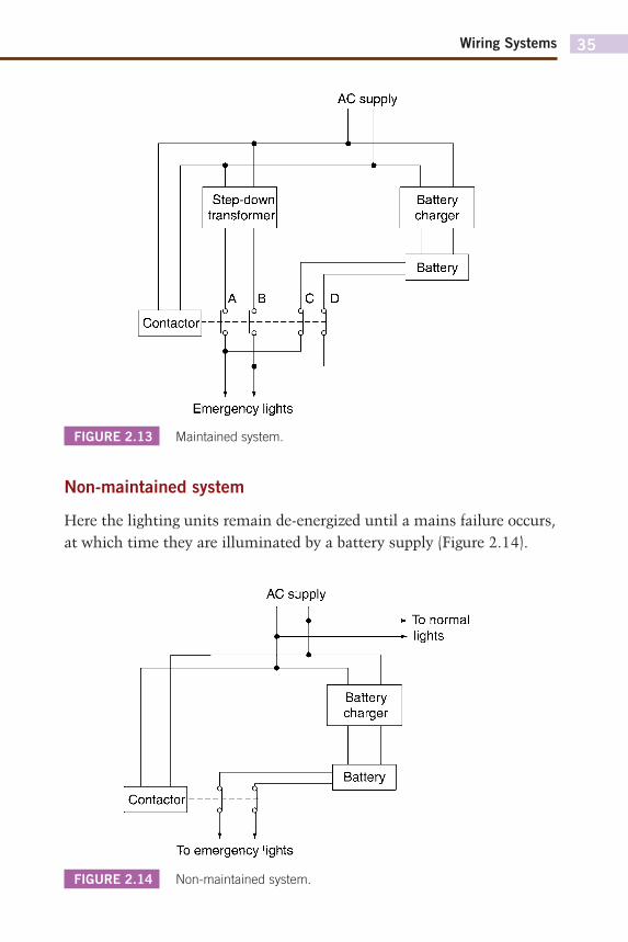
Maintained system
In this system the emergency lighting unit is energized continuously via a step-down transformer, and in the event of a mains failure it remains illuminated via a battery (Figure 2.13, see page 35).
FIGURE 2.10 Floor plan for garage/workshop.
BrBkGrI 2? Gr4
2 Bk5 B k 5 X 2
2 ^ Gr4 7,
bf
Br5
2
Br5
2 Compressor room
P^P- 7 ^ Br4 I- BrBkGr2 ■
X 2 § k 5 11
Wiring Systems 33
FIG
UR
E 2
.11
D
eta
ils o
f connection d
iagra
m f
or
gara
ge/w
ork
shop.
Type
Br1
Bk1
Gr1
Br2
Bk2
Gr2
Br3
Bk3
Gr3
Br4
Bk4
Gr4
Br5
Bk5
Gr5
Br6
Bk6
Gr6
C
C
C
C C
C B B B B B B B B
10A
10A
10A
30 A
30 A
30 A
10A
10A
10A
10A
15A
30 A
30 A
30 A
Thre
e-ph
ase
supp
ly to
ra
mp
Thre
e-ph
ase
supp
ly to
co
mpr
esso
r
WS
light
ing
4
WS
light
ing
2
WS
light
ing
3
Offi
ce, W
C, s
tore
and
co
mpr
esso
r ro
om li
ghtin
g W
S, w
ater
hea
ter
SOs
2 an
d 3,
radi
al
SOs
5 an
d 6,
radi
al
SOs
9, 1
1 an
d 13
, rad
ial
100
A DB
with
mai
n sw
itch
prot
ectio
n by
MCB
2 2
3 x
1.5 m
m s
ingl
es +
1 m
m c
pc
Isol
ator
10
A 10
A
-G)
2 2
Isol
ator
28
A
3 x
10 m
m s
ingl
es +
1.5
mm
cpc
■
■ 30
A
2 2
2 x
1.5 m
m s
ingl
es +
1 m
m c
pc
2 2
2 x
1.5 m
m s
ingl
es +
1 m
m c
pc
2 2
2 x
1.5 m
m s
ingl
es +
1 m
m c
pc
2 2
2 x
1.5 m
m s
ingl
es +
1 m
m c
pc
2 2
2x2
.5 m
m s
ingl
es +
1 m
m c
pc
=| 3
x 1
25 W
200
0 m
m d
oubl
es
=| 3
x 1
25 W
200
0 m
m d
oubl
es
=| 3
x 1
25 W
200
0 m
m d
oubl
es
^ 3
x 12
5 W
200
0 m
m a
nd
8 x
80 W
120
0 m
m d
oubl
es
-&
Fuse
d sp
ur b
ox
2 2
2 x
6.0
mm
sin
gles
+ 1
.5 m
m c
pc
2^ 2
^ 2
2 2
x 6.
0 m
m s
ingl
es +
1.5
mm
cpc
2^
2^
2 2
2 x
6.0m
m
singl
es +
1.5
mm
cp
c 2^
2^
2V
Wiring Systems and Fault Finding34
FIG
UR
E 2
.12
C
onnection d
iagra
m for
part
of ve
ntila
tion s
chem
e (
det.
: dete
cto
r).
Roo
m A
NV
det.
As
Zone
1
Zone
2
Diff
eren
tial
■^
r~
^ r~
Zone
3
"̂
r Zo
ne 4
MV
18
(fros
t) Ex
tract
pr
essu
re
Extra
ct
^p
piy
de
t. sw
itch
Supp
ly
\Air
inta
ke
det
7x
15
mm
2 PV
C.
12
x1.5
mm
2 PVC
2
x4
mm
2 PVC
Extra
ct
det.
MV3
Extra
ct
MV6
Ext
ract
s M
V5
det.
6Q^
| Ex
tract
de
t. Su
pply
de
t.
D9
D10
D
11
D12
Supp
ly
det.
det.
D13
MV5
D14
Con
trol p
anel
Wiring Systems 35
Non-maintained system
Here the lighting units remain de-energized until a mains failure occurs, at which time they are illuminated by a battery supply (Figure 2.14).
FIGURE 2.13 Maintained system.
FIGURE 2.14 Non-maintained system.
AC supply
Step-down transformer
Contactor
A
f-f In lç
V Q
Battery charger
Battery
Emergency lights
AC supply
To emergency lights
To normal lights
Battery charger
Battery
Wiring Systems and Fault Finding36
It should be noted that modern systems use electronic means to provide the change-over from mains to battery supply. The contactor method, however, serves to illustrate the principle of operation.
SECURITY AND FIRE ALARM SYSTEMS
As with emergency lighting, modern security and fire alarm systems are electronically controlled, and it is not the brief of this book to investigate electronic circuitry. However, as with the previous section, the basic principle of operation can be shown by electro-mechanical means.
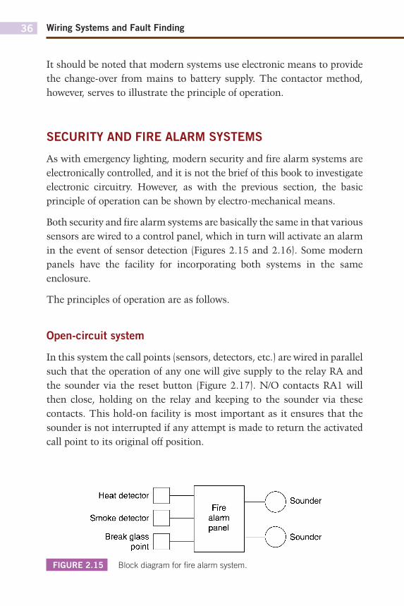
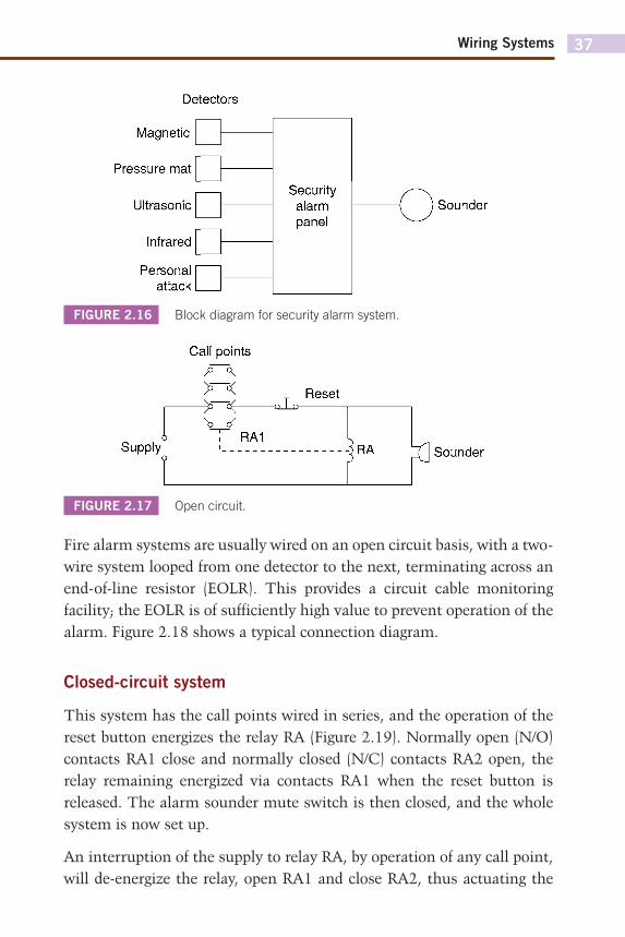
Both security and fire alarm systems are basically the same in that various sensors are wired to a control panel, which in turn will activate an alarm in the event of sensor detection (Figures 2.15 and 2.16). Some modern panels have the facility for incorporating both systems in the same enclosure.
The principles of operation are as follows.
Open-circuit system
In this system the call points (sensors, detectors, etc.) are wired in parallel such that the operation of any one will give supply to the relay RA and the sounder via the reset button (Figure 2.17). N/O contacts RA1 will then close, holding on the relay and keeping to the sounder via these contacts. This hold-on facility is most important as it ensures that the sounder is not interrupted if any attempt is made to return the activated call point to its original off position.
FIGURE 2.15 Block diagram for fi re alarm system.
Heat detector
Smoke detector
Break glass point
Fire alarm panel
/-~-\ ( \
\J r^\ \ ) v_y
Wiring Systems 37
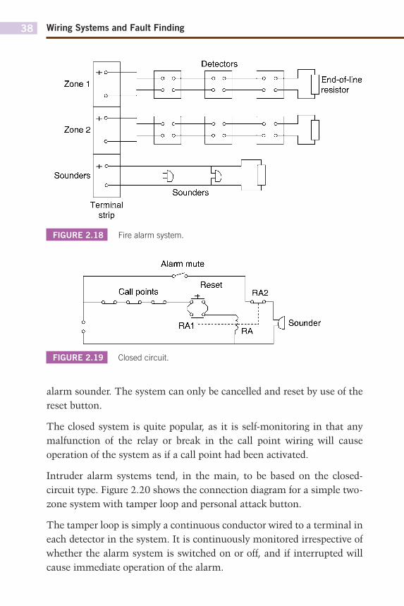
Fire alarm systems are usually wired on an open circuit basis, with a two-wire system looped from one detector to the next, terminating across an end-of-line resistor (EOLR). This provides a circuit cable monitoring facility; the EOLR is of sufficiently high value to prevent operation of the alarm. Figure 2.18 shows a typical connection diagram.
Closed-circuit system
This system has the call points wired in series, and the operation of the reset button energizes the relay RA (Figure 2.19). Normally open (N/O) contacts RA1 close and normally closed (N/C) contacts RA2 open, the relay remaining energized via contacts RA1 when the reset button is released. The alarm sounder mute switch is then closed, and the whole system is now set up.
An interruption of the supply to relay RA, by operation of any call point, will de-energize the relay, open RA1 and close RA2, thus actuating the
FIGURE 2.16 Block diagram for security alarm system.
FIGURE 2.17 Open circuit.
Detectors
Magnetic
Pressure mat
Ultrasonic
Infrared
Personal attack
Security alarm panel
-f j Sounder
Call points
>> Ce Q_l_0-Reset
Supply RA1
R A Y ] Sounder
Wiring Systems and Fault Finding38
alarm sounder. The system can only be cancelled and reset by use of the reset button.
The closed system is quite popular, as it is self-monitoring in that any malfunction of the relay or break in the call point wiring will cause operation of the system as if a call point had been activated.
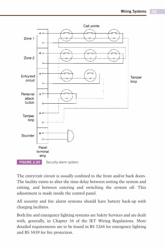
Intruder alarm systems tend, in the main, to be based on the closed-circuit type. Figure 2.20 shows the connection diagram for a simple two-zone system with tamper loop and personal attack button.
The tamper loop is simply a continuous conductor wired to a terminal in each detector in the system. It is continuously monitored irrespective of whether the alarm system is switched on or off, and if interrupted will cause immediate operation of the alarm.
FIGURE 2.18 Fire alarm system.
FIGURE 2.19 Closed circuit.
Zone 1
Zone 2
Sounders
1
+ 0
o
H-o
0
H- o
'ermina
1
1 —o o—
1
1 —o o—
Detectors — n—
—0 O—
—0 O—
1
Sounders 1
il
-O O-
-o o-
-o o-
-o o-
End-of-line resistor
Alarm mute o--b
Call points Reset
RA2
RA1 : l " R A - J p u Sounder
Wiring Systems 39
The entry/exit circuit is usually confined to the front and/or back doors. The facility exists to alter the time delay between setting the system and exiting, and between entering and switching the system off. This adjustment is made inside the control panel.
All security and fire alarm systems should have battery back-up with charging facilities.
Both fire and emergency lighting systems are Safety Services and are dealt with, generally, in Chapter 56 of the IET Wiring Regulations. More detailed requirements are to be found in BS 5266 for emergency lighting and BS 5839 for fire protection.
FIGURE 2.20 Security alarm system.
Call points
Zone 1
Zone 2
0---J- V--0--
Entry/exit circuit
Personal attack button
Tamper loop
Tamper loop
Sounder
Panel terminal
strip
Wiring Systems and Fault Finding40
CALL SYSTEMS
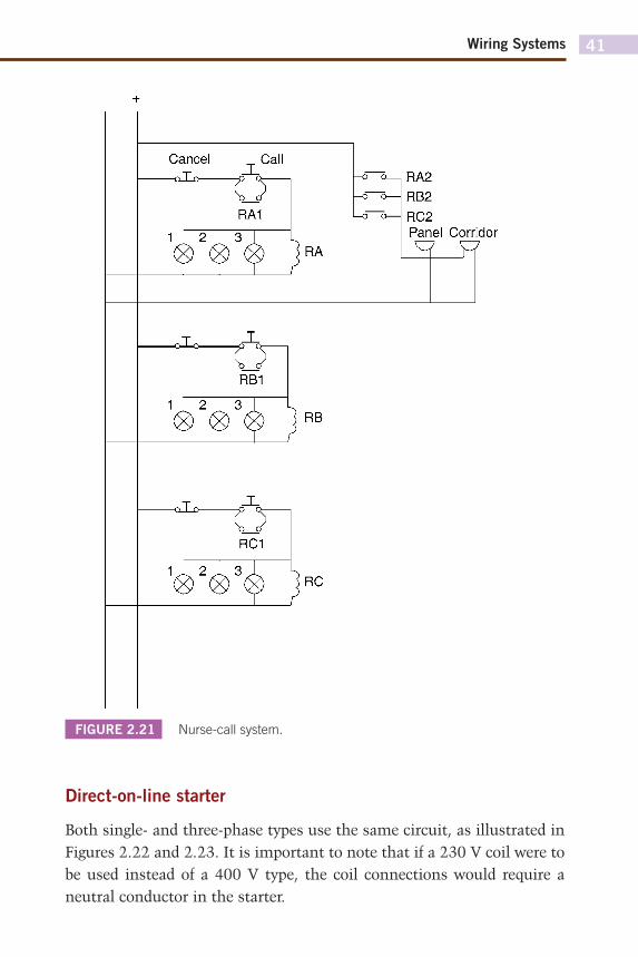
Once again these fall into different categories, such as telephone systems and page and bleeper systems. However, the typical nurse-call variety, which uses push-buttons and lamp indication, is probably the most popular.
With this type, each room is equipped with a call button of some description, a patient’s reassurance light and a cancel button. Outside each room is an indicator light, and at strategic points in the building are zone sounders. Centrally located is a display panel which incorporates a sounder and an indication of which room is calling.
Figure 2.21 illustrates, in a simple form, the principle of operation of such a system. This system should, by now, be quite familiar to the reader; it is simply another variation of the hold-on circuit. Any patient pushing a call button energizes the corresponding relay in the main control panel, which is held on by a pair of N/O contacts. At the same time the reassurance, room and panel lights 1, 2 and 3 are all illuminated. The zone and panel sounders are energized via the relay’s other pair of N/O contacts.
It is usual to locate cancel buttons in patient’s rooms only, as this ensures that staff visit the patient in question.
All of the systems just dealt with are generally supplied from an extra low-voltage (ELV) source and are known as Band I circuits. These should not be contained within the same wiring system as low voltage (LV) systems which are Band II circuits unless they are insulated to the highest voltage present or, if in trunking, segregated by a partition.
MOTOR STARTER CIRCUITS
No book on wiring systems would be complete without reference to control circuits for motor starters. Here we will look at direct-on-line (DOL) and star-delta starters. Once more, the good old hold-on circuit is employed in both types.
Wiring Systems 41
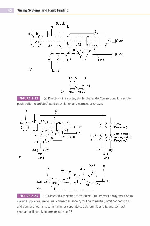
Direct-on-line starter
Both single- and three-phase types use the same circuit, as illustrated in Figures 2.22 and 2.23. It is important to note that if a 230 V coil were to be used instead of a 400 V type, the coil connections would require a neutral conductor in the starter.
FIGURE 2.21 Nurse-call system.
Cancel Call —r>To
RA1
1 1 2 1 3 RA
RA2 RB2 RC2 Panel Corridor
JLc
RB1
1 1 2 1 3 RB
—Q_LO—
RC1
I l 2 l 3 RC
Wiring Systems and Fault Finding42
FIGURE 2.22 (a) Direct-on-line starter, single phase. (b) Connections for remote
push-button (start/stop) control: omit link and connect as shown.
FIGURE 2.23 (a) Direct-on-line starter, three phase. (b) Schematic diagram. Control
circuit supply: for line to line, connect as shown; for line to neutral, omit connection D
and connect neutral to terminal a; for separate supply, omit D and E, and connect
separate coil supply to terminals a and 15.
Supply N L
Load
15 16 7
i A o o O/L ouu ouo-1
(b) Start Stop
A(U) C(W) B(V) Load
Fuses (if required)
u u Motor circuit L--JÏ---A isolating switch
9 'Q '9 (if required)
L1(R) L3(T) L2(S) Line
Start
Wiring Systems 43
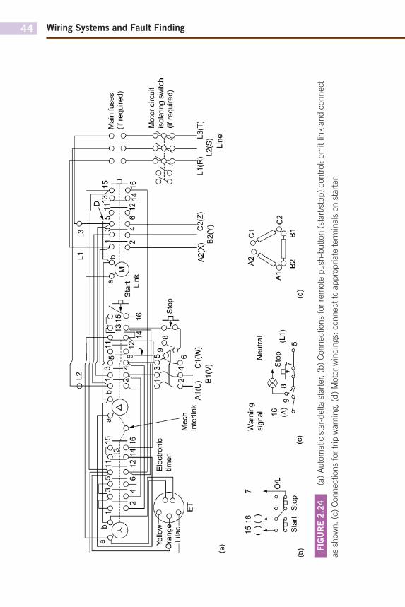
Star-delta starter
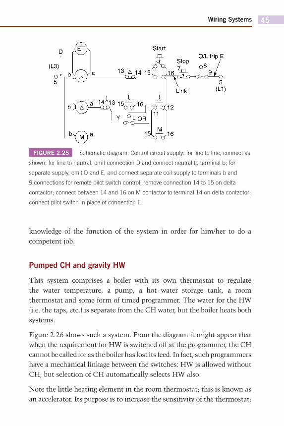
Figures 2.24 and 2.25 show the wiring and schematic diagrams for a star-delta starter. This is clearly a more complicated system than the DOL type. However, the control system is essentially the same. On start-up, the star contactor, electronic timer and the main contactor are all energized. At the end of the set time the supply to the star contactor is removed and given to the delta contactor, the main contactor remaining energized the whole time. Reference to Figure 2.25 will indicate how the system functions.
1. When the start is pushed, supply is given to the star contactor and the timer ET, from L1 to L3, and hence all contacts marked associated with the star contactor will change position. The supply to and ET is maintained, after the start is released, via star contacts 11 and 12, ET contacts OR-Y, and star contacts 15 and 16. The main contactor M is also energized via star contacts 11 and 12, and M15, and thereafter maintained via its own contacts M15 and 16.
2. The motor has of course started, and after a predetermined time delay ET operates and its contacts OR-Y change to OR-L. This cuts off supply to the star contactor and also ET. All star contacts return to normal, and ET resets OR-11 to OR-Y.
3. Supply is now given to the delta contactor Δ via M15 and 16, OR-Y, and star contacts 13 and 14. Delta contacts Δ 13 and 14 open and prevent further energization of the star contactor.
The reader will notice that the line and load terminal markings in Figure 2.24a show letters in brackets; these are the European equivalents.
CENTRAL HEATING SYSTEMS
It would be impossible in such a small book to deal with the vast number of modern systems and variations that are currently available. We will therefore take a look at the two most basic arrangements: the pumped central heating (CH) and gravity-fed hot water (HW) system, and the fully pumped system with mid-position valve. It must be remembered that, whatever the system, it is imperative that the wiring installer has a
Wiring Systems and Fault Finding44
FIG
UR
E 2
.24
(a
) A
uto
matic s
tar-
delta s
tart
er. (
b)
Connections
for
rem
ote
push
-butt
on (
start
/sto
p)
contr
ol: o
mit lin
k a
nd
con
nect
as
show
n. (c
) C
onnections
for
trip
warn
ing. (d
) M
oto
r w
indin
gs:
connect
to a
ppro
priate
term
inals
on s
tart
er.
d) L
2 L1
L3
6"
I—Li
lac
(a)
^T
fJ
^ ^
St8Lin
K " ?
2?t?
ïstë
15 P
Mec
h in
terli
nk
so-A1
(U)
C1(
W)
B1(V
)
6 12
14T1
6
A2(X
) C
2(Z)
B2
(Y)
6 6
6 M
ain
fuse
s O
O
O
(if
reclu
ire
d)
O/O
m
Mot
or c
ircui
t is
olat
ing
switc
h (if
req
uire
d)
L1(R
) ■
L3(T
) L2
(S)
Line
15 1
6 (
)( )
(b)
o A
o o
o u
o o
u o—
' St
art
Stop
O/L
War
ning
si
gnal
16
Neu
tral
(c)
(A)
g^
8 _
^t
0P
^ (L
1)
"5
(d)
A2
no
C1
A1
0o
^^
o0
C2
B2
B1
Wiring Systems 45
knowledge of the function of the system in order for him/her to do a competent job.
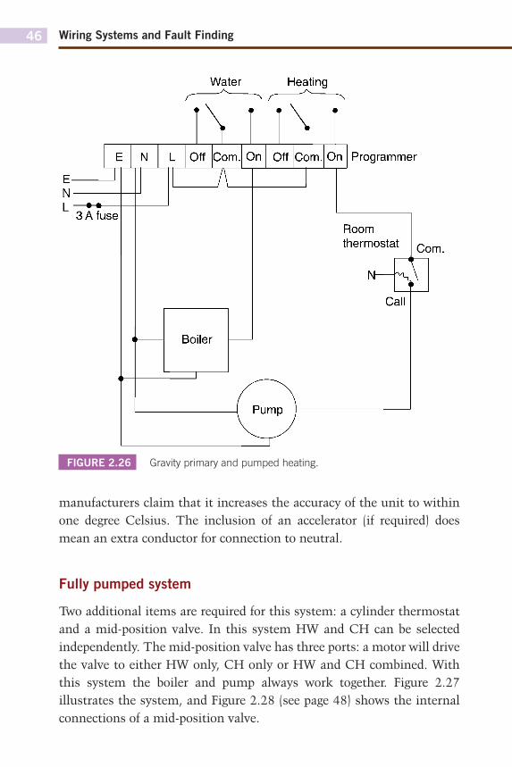
Pumped CH and gravity HW
This system comprises a boiler with its own thermostat to regulate the water temperature, a pump, a hot water storage tank, a room thermostat and some form of timed programmer. The water for the HW (i.e. the taps, etc.) is separate from the CH water, but the boiler heats both systems.
Figure 2.26 shows such a system. From the diagram it might appear that when the requirement for HW is switched off at the programmer, the CH cannot be called for as the boiler has lost its feed. In fact, such programmers have a mechanical linkage between the switches: HW is allowed without CH, but selection of CH automatically selects HW also.
Note the little heating element in the room thermostat; this is known as an accelerator. Its purpose is to increase the sensitivity of the thermostat;
FIGURE 2.25 Schematic diagram. Control circuit supply: for line to line, connect as
shown; for line to neutral, omit connection D and connect neutral to terminal b; for
separate supply, omit D and E, and connect separate coil supply to terminals b and
9 connections for remote pilot switch control: remove connection 14 to 15 on delta
contactor; connect between 14 and 16 on M contactor to terminal 14 on delta contactor;
connect pilot switch in place of connection E.
ET
(L3)
CM 5
Start
NT" Stop 0/L trip E
A b l A
14*13 15— , , „
Link
Y ^ L 0 R |
M 15 16
Wiring Systems and Fault Finding46
manufacturers claim that it increases the accuracy of the unit to within one degree Celsius. The inclusion of an accelerator (if required) does mean an extra conductor for connection to neutral.
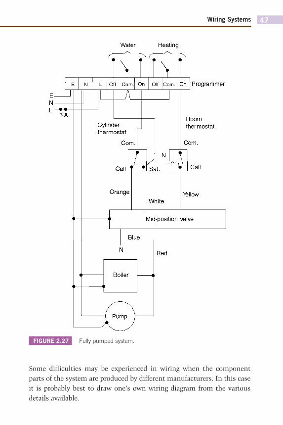
Fully pumped system
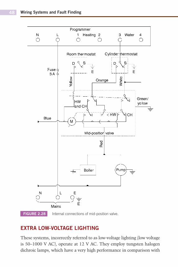
Two additional items are required for this system: a cylinder thermostat and a mid-position valve. In this system HW and CH can be selected independently. The mid-position valve has three ports: a motor will drive the valve to either HW only, CH only or HW and CH combined. With this system the boiler and pump always work together. Figure 2.27 illustrates the system, and Figure 2.28 (see page 48) shows the internal connections of a mid-position valve.
FIGURE 2.26 Gravity primary and pumped heating.
r Water Heating
~^
X 3 A fuse
Boiler
N L Off Corn. On Off Corn. On Programmer
Room thermostat Corn.
Ko Call
Wiring Systems 47
Some difficulties may be experienced in wiring when the component parts of the system are produced by different manufacturers. In this case it is probably best to draw one’s own wiring diagram from the various details available.
FIGURE 2.27 Fully pumped system.
Water Heating
r • •
Off Com.
~K \1V\
On
Cylinder thermostat
Com.
Call
Off Com. On
Orange
/ J N \ Sat.
White
Programmer
Room thermostat
Com.
Call
Nèllow
Mid-position valve
Blue
N Red
Boiler
Wiring Systems and Fault Finding48
EXTRA LOW-VOLTAGE LIGHTING
These systems, incorrectly referred to as low-voltage lighting (low voltage is 50–1000 V AC), operate at 12 V AC. They employ tungsten halogen dichroic lamps, which have a very high performance in comparison with
FIGURE 2.28 Internal connections of mid-position valve.
Programmer 1 Heating 2
o o 3 Water 4
Wiring Systems 49
240 V halogen lamps. For example, a 50 W dichroic lamp has the same intensity as a 150 W PAR lamp.
Extra low-voltage (ELV) lighting is becoming very popular, especially for display purposes. There is very little heat emission, the colour rendering is excellent and energy consumption is very low.
The 12 V AC to supply the lamps is derived from a 230 V/12 V transformer specially designed to cater for the high starting surges, and only these types should be used. The voltage at each lamp is critical: 0.7 V overvoltage can cause premature ageing of the lamp, and 0.7 V undervoltage will reduce the light output by 30%. Hence the variation in voltage must be avoided.
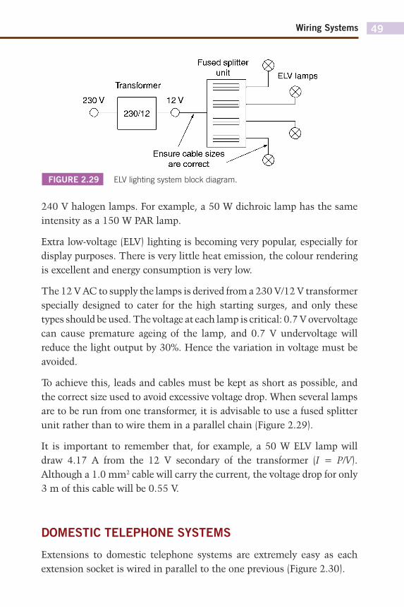
To achieve this, leads and cables must be kept as short as possible, and the correct size used to avoid excessive voltage drop. When several lamps are to be run from one transformer, it is advisable to use a fused splitter unit rather than to wire them in a parallel chain (Figure 2.29).
It is important to remember that, for example, a 50 W ELV lamp will draw 4.17 A from the 12 V secondary of the transformer (I = P/V). Although a 1.0 mm2 cable will carry the current, the voltage drop for only 3 m of this cable will be 0.55 V.
DOMESTIC TELEPHONE SYSTEMS
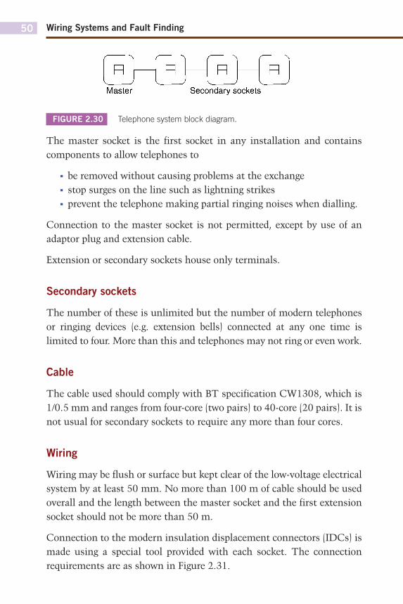
Extensions to domestic telephone systems are extremely easy as each extension socket is wired in parallel to the one previous (Figure 2.30).
FIGURE 2.29 ELV lighting system block diagram.
Transformer
Fused splitter unit
230/12 12V
Ensure cable sizes are correct
Wiring Systems and Fault Finding50
The master socket is the first socket in any installation and contains components to allow telephones to
■ be removed without causing problems at the exchange■ stop surges on the line such as lightning strikes■ prevent the telephone making partial ringing noises when dialling.
Connection to the master socket is not permitted, except by use of an adaptor plug and extension cable.
Extension or secondary sockets house only terminals.
Secondary sockets
The number of these is unlimited but the number of modern telephones or ringing devices (e.g. extension bells) connected at any one time is limited to four. More than this and telephones may not ring or even work.
Cable
The cable used should comply with BT specification CW1308, which is 1/0.5 mm and ranges from four-core (two pairs) to 40-core (20 pairs). It is not usual for secondary sockets to require any more than four cores.
Wiring
Wiring may be flush or surface but kept clear of the low-voltage electrical system by at least 50 mm. No more than 100 m of cable should be used overall and the length between the master socket and the first extension socket should not be more than 50 m.
Connection to the modern insulation displacement connectors (IDCs) is made using a special tool provided with each socket. The connection requirements are as shown in Figure 2.31.
FIGURE 2.30 Telephone system block diagram.
n R R R Master Secondary sockets
n R R R Master Secondary sockets

Wiring Systems 51
FIGURE 2.31 Secondary socket wiring.
Master Adaptor
Colour code
Terminal
2
3
4
5
Colour
Blue with white stripe
Orange with white stripe
White with orange stripe
White with blue stripe
1 3
Secondary sockets
O Extension
bell
53
CHAPTER 3
Testing and Test Instruments
Important terms/topics covered in this chapter:
■ Inspection■ Electrical quantities■ Selection of test instruments■ Approved test lamps and voltage indicators■ Care of instruments ■ Tests and testing
At the end of this chapter the reader should:
■ know the instrument ranges and measurement quantities,■ be able to identify the correct certification documents to be completed,■ be aware of the importance of having accurate instrumentation,■ know the correct method of proving a circuit is dead and safe to
work on,■ be able to list the relevant tests and the sequence in which they
should be conducted,■ understand the theory behind, and the methods of, testing,■ understand and interpret test results.
Whilst this section deals with testing, it should be remembered that such action should always be preceded by inspection as this may reveal faults, damage, deterioration, etc., that cannot be detected by testing alone.
MEASUREMENT OF ELECTRICAL QUANTITIES
As the reader will know, the basic electrical quantities which need to be measured in the world of the installation electrician are current, voltage and resistance. The units of these quantities are the ampere, the volt and the ohm, respectively.
Wiring Systems and Fault Finding54
Paradoxically, however, the range and complexity of the instruments available to measure these three fundamental quantities are enormous. So where does one start in order to make a choice of the most suitable types?
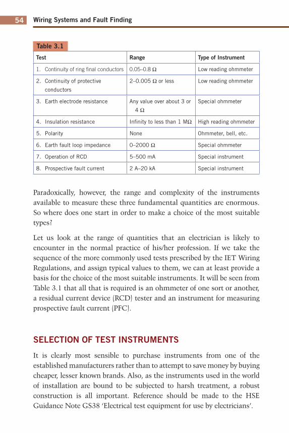
Let us look at the range of quantities that an electrician is likely to encounter in the normal practice of his/her profession. If we take the sequence of the more commonly used tests prescribed by the IET Wiring Regulations, and assign typical values to them, we can at least provide a basis for the choice of the most suitable instruments. It will be seen from Table 3.1 that all that is required is an ohmmeter of one sort or another, a residual current device (RCD) tester and an instrument for measuring prospective fault current (PFC).
SELECTION OF TEST INSTRUMENTS
It is clearly most sensible to purchase instruments from one of the established manufacturers rather than to attempt to save money by buying cheaper, lesser known brands. Also, as the instruments used in the world of installation are bound to be subjected to harsh treatment, a robust construction is all important. Reference should be made to the HSE Guidance Note GS38 ‘Electrical test equipment for use by electricians’.
Table 3.1
Test Range Type of Instrument
1. Continuity of ring fi nal conductors 0.05–0.8 Ω Low reading ohmmeter
2. Continuity of protective
conductors
2–0.005 Ω or less Low reading ohmmeter
3. Earth electrode resistance Any value over about 3 or
4 ΩSpecial ohmmeter
4. Insulation resistance Infi nity to less than 1 MΩ High reading ohmmeter
5. Polarity None Ohmmeter, bell, etc.
6. Earth fault loop impedance 0–2000 Ω Special ohmmeter
7. Operation of RCD 5–500 mA Special instrument
8. Prospective fault current 2 A–20 kA Special instrument
Testing and Test Instruments 55
Many of the well-known instrument companies provide a dual facility in one instrument, for example PFC and loop impedance, or insulation resistance and continuity. Hence it is likely that only one, three or four instruments would be needed, together with an approved test lamp (a subject to be dealt with in the next section).
Now, which type to choose, analogue or digital? There are merits in both varieties, and the choice should not be determined just by expense or a reluctance to use ‘new-fangled electronic gadgetry’! This attitude has, however, become a thing of the past, and an analogue variety would prob-ably only be purchased second hand! Accuracy, ease of use and robustness, together with personal preference, are the all-important considerations.
APPROVED TEST LAMPS AND VOLTAGE INDICATORS
Search your tool boxes; find, with little difficulty one would suspect, your ‘neon screwdriver’ or ‘testascope’; locate a very deep pond; and drop it in!
Imagine actually allowing electric current at low voltage (50–1000 V AC) to pass through one’s body in order to activate a test lamp! It only takes around 10–15 mA to cause severe electric shock, and 50 mA (1/20th of an ampere) to kill.
Apart from the fact that such a device will register any voltage from about 5 V upwards, the safety of the user depends entirely on the integrity of the current-limiting resistor in the unit. An electrician received a considerable shock when using such an instrument after his apprentice had dropped it in a sink of water, simply wiped it dry and replaced it in the tool box. The water had seeped into the device and shorted out the resistor.
It should be said, however, that some modern types are available that are proximity devices and can give an indication of the presence of voltage. Such a device should never be relied on to suggest that a circuit is dead and safe to work on. It could be useful to indicate if a fuse had operated by placing it either side.
An approved test lamp should be of similar construction to that shown in Figure 3.1.
Wiring Systems and Fault Finding56
ACCIDENTAL RCD OPERATION
It has long been the practice when using a test lamp to probe between line and earth for indication of a live supply on the line terminal. However, this can now prevent a problem where RCDs exist in the circuit, as of course the test is applying a deliberate line to earth fault.
Some test lamps have LED indicators, and the internal circuitry of such test lamps limits the current to earth to a level below that at which RCD will operate. The same limiting effect applies to multimeters. However, it is always best to check that the testing device will have no effect on RCDs.
CALIBRATION, ZEROING AND CARE OF INSTRUMENTS
Precise calibration of instruments is usually well outside the province of the electrician, and would normally be carried out by the manufacturer or
FIGURE 3.1 Approved test lamp.
/ w L a m p
Maximum test
voltage marked
v ^
Fused test probes
— Finger guards-
— Insulation 2 mm exposed
or spring-loaded enclosed tips
Insulated lead
= 0 ^ o
Testing and Test Instruments 57
a local service representative. A check, however, can be made by the user to determine whether calibration is necessary by comparing readings with an instrument known to be accurate, or by measurement of known values of voltage, resistance, etc., available on units now on the market and advertised as ‘check boxes’.
It may be the case that readings are incorrect simply because the instrument is not zeroed or nulled before use, or because the internal battery needs replacing. Most modern instruments have battery condition indication, and of course this should never be ignored.
Always adjust any selection switches to the off position after testing. Too many instrument fuses are blown when, for example, a multimeter is inadvertently left on the ohms range and then used to check for mains voltage.
The following procedure may seem rather basic but should ensure trouble-free testing:
1. Check test leads for obvious defects.2. Zero/null the instrument (where required).3. Select the correct range for the values anticipated. If in doubt,
choose the highest range and gradually drop down.4. Make a record of test results, if necessary.5. Return switches/selectors to the off position.6. Replace instrument leads in carrying case.
CONTINUITY OF PROTECTIVE CONDUCTORS
All protective conductors, including main protective and supplementary bonding conductors must be tested for continuity using a low-resistance ohmmeter.
For main protective bonding there is no single fixed value of resistance above which the conductor would be deemed unsuitable.
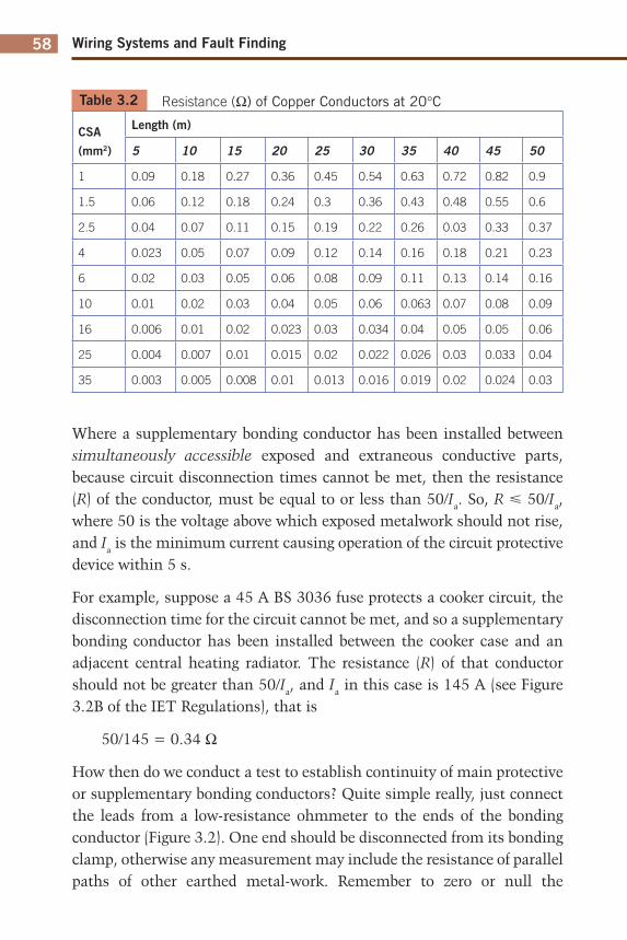
Each measured value, if indeed it is measurable for very short lengths, should be compared with the relevant value for a particular conductor length and size. Such values are shown in Table 3.2.
Wiring Systems and Fault Finding58
Table 3.2 Resistance (Ω) of Copper Conductors at 20°C
CSA
(mm2)
Length (m)
5 10 15 20 25 30 35 40 45 50
1 0.09 0.18 0.27 0.36 0.45 0.54 0.63 0.72 0.82 0.9
1.5 0.06 0.12 0.18 0.24 0.3 0.36 0.43 0.48 0.55 0.6
2.5 0.04 0.07 0.11 0.15 0.19 0.22 0.26 0.03 0.33 0.37
4 0.023 0.05 0.07 0.09 0.12 0.14 0.16 0.18 0.21 0.23
6 0.02 0.03 0.05 0.06 0.08 0.09 0.11 0.13 0.14 0.16
10 0.01 0.02 0.03 0.04 0.05 0.06 0.063 0.07 0.08 0.09
16 0.006 0.01 0.02 0.023 0.03 0.034 0.04 0.05 0.05 0.06
25 0.004 0.007 0.01 0.015 0.02 0.022 0.026 0.03 0.033 0.04
35 0.003 0.005 0.008 0.01 0.013 0.016 0.019 0.02 0.024 0.03
Where a supplementary bonding conductor has been installed between simultaneously accessible exposed and extraneous conductive parts, because circuit disconnection times cannot be met, then the resistance (R) of the conductor, must be equal to or less than 50/Ia. So, R � 50/Ia, where 50 is the voltage above which exposed metalwork should not rise, and Ia is the minimum current causing operation of the circuit protective device within 5 s.
For example, suppose a 45 A BS 3036 fuse protects a cooker circuit, the disconnection time for the circuit cannot be met, and so a supplementary bonding conductor has been installed between the cooker case and an adjacent central heating radiator. The resistance (R) of that conductor should not be greater than 50/Ia, and Ia in this case is 145 A (see Figure 3.2B of the IET Regulations), that is
50/145 = 0.34 Ω
How then do we conduct a test to establish continuity of main protective or supplementary bonding conductors? Quite simple really, just connect the leads from a low-resistance ohmmeter to the ends of the bonding conductor (Figure 3.2). One end should be disconnected from its bonding clamp, otherwise any measurement may include the resistance of parallel paths of other earthed metal-work. Remember to zero or null the
Testing and Test Instruments 59
instrument or, if this facility is not available, record the resistance of the test leads so that this value can be subtracted from the test reading.
Important Note
If the installation is in operation, then never disconnect main protective bonding
conductors unless the supply can be isolated. Without isolation, persons and livestock
are at risk of electric shock.
The continuity of circuit protective conductors (cpcs) may be established in the same way, but a second method is preferred, as the results of this second test indicate the value of (R1 + R2) for the circuit in question.
The test is conducted in the following manner:
1. Temporarily link together the line conductor and cpc of the circuit concerned in the distribution board or consumer unit.
2. Test between line and cpc at each outlet in the circuit. A reading indicates continuity.
3. Record the test result obtained at the furthest point in the circuit. This value is (R1 + R2) for the circuit.
FIGURE 3.2 Testing for continuity.
Disconnect only if supply is isolated
Earth clamp with label >
Zero/null instrument or subtract test lead résistance Water
Wiring Systems and Fault Finding60
Figure 3.3 illustrates the above method. There may be some difficulty in determining the (R1 + R2) values of circuits in installations that comprise steel conduit and trunking, and/or SWA and MI cables because of the parallel earth paths that are likely to exist. In these cases, continuity tests may have to be carried out at the installation stage before accessories are connected or terminations made off as well as after completion.
Although it is no longer considered good working practice to use steel conduit or trunking as a protective conductor, it is permitted, and hence its continuity must be proved. The enclosure must be inspected along its length to ensure that it is sound and then the standard low-resistance test is performed.
CONTINUITY OF RING FINAL CIRCUIT CONDUCTORS
There are two main reasons for conducting this test:
1. To establish that interconnections in the ring do not exist.2. To ensure that the cpc is continuous, and indicate the value of
(R1 + R2) for the ring.
What then are interconnections in a ring circuit, and why is it important to locate them? Figure 3.4 shows a ring final circuit with an interconnection.
FIGURE 3.3 Testing cpc continuity.
Reading at last outlet gives (R H- R2) value for the circuit
Testing and Test Instruments 61
The most likely cause of the situation shown in Figure 3.4 is where a DIY enthusiast has added sockets P, Q, R and S to an existing ring A, B, C, D, E and F.
In itself there is nothing wrong with this. The problem arises if a break occurs at, say, point Y, or the terminations fail in socket C or P. Then there would be four sockets all fed from the point X which would then become a spur.
So, how do we identify such a situation with or without breaks at point ‘Y’? A simple resistance test between the ends of the line, neutral or cpc’s will only indicate that a circuit exists, whether there are interconnections or not. The following test method is based on the philosophy that the resistance measured across any diameter of a perfect circle of conductor will always be the same value (Figure 3.5).
The perfect circle of conductor is achieved by cross connecting the line and neutral legs of the ring (Figure 3.6).
The test procedure is as follows:
1. Identify the opposite legs of the ring. This is quite easy with sheathed cables, but with singles, each conductor will have to be identified, probably by taking resistance measurements between each one and the closest socket outlet. This will give three high readings and three low readings thus establishing the opposite legs.
2. Take a resistance measurement between the ends of each conductor loop. Record this value.
FIGURE 3.4 Ring circuit with interconnection.
I 1
A
® ®
B
I ® ®
Interconnection
. ■ . . ■ .
c . ■ »
. '
Y P
1 ® ®
C !
® ■ !
1 „ X
e e . ■ " n
D / S Spur
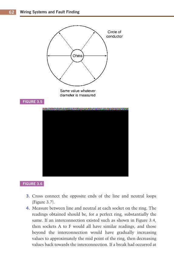
Wiring Systems and Fault Finding62
3. Cross connect the opposite ends of the line and neutral loops (Figure 3.7).
4. Measure between line and neutral at each socket on the ring. The readings obtained should be, for a perfect ring, substantially the same. If an interconnection existed such as shown in Figure 3.4, then sockets A to F would all have similar readings, and those beyond the interconnection would have gradually increasing values to approximately the mid point of the ring, then decreasing values back towards the interconnection. If a break had occurred at
FIGURE 3.5
FIGURE 3.6
Circle of conductor
Ohms}
Same value whatever diameter is measured
L1 - N2
Lin 00
® ■ ®
3
0
®J_®
Neutral loop
L2 N1
Testing and Test Instruments 63
point Y then the readings from socket S would increase to a maximum at socket P. One or two high readings are likely to indicate either loose connections or spurs. A null reading (i.e. an open-circuit indication) is probably a reverse polarity, either line- or neutral-cpc reversal. These faults would clearly be rectified and the test at the suspect socket(s) repeated.
5. Repeat the above procedure, but in this case cross connect the line and cpc loops (Figure 3.8).
In this instance, if the cable is of the flat twin type, the readings at each socket will increase very slightly and then decrease around the ring. This difference, due to the line and cpc being different sizes, will not be significant enough to cause any concern. The measured value is very important, it is R1 + R2 for the ring.
As before, loose connections, spurs and, in this case, L–N cross polarity will be picked up.
FIGURE 3.7 L and N cross connections.
FIGURE 3.8 L and cpc cross connections.
L1 N1
Wiring Systems and Fault Finding64
Table 3.3
L1–P2 N1–N2 cpc 1–cpc 2
Initial measurements 0.52 0.52 0.86
Reading at each socket 0.26 0.26 0.32–0.34
For spurs, each metre in length will add the following
resistance to the above values
0.015 0.015 0.02
The details in Table 3.3 are typical approximate ohmic values for a healthy 70 m ring final circuit wired in 2.5/1.5 flat twin and cpc cable. (In this case the cpc will be approximately 1.67 X the L or N resistance.)
As already mentioned, null readings may indicate a reverse polarity. They could also indicate twisted conductors not in their terminal housing. The examples shown in Figure 3.9 may help to explain these situations.
FIGURE 3.9
Socket A B C
L-N Reading OK
No Reading No Reading
L-cpc Reading No Reading OK
No Reading
®
L
1 cpc
N
® L-N reversai or twisted cpcs not in terminal
®
■ N
I I
■ cpc
® L-cpc reversai or twisted Ns not in terminal
I N
cpc V
N-cpc reversai or twisted Ls not in terminal
Testing and Test Instruments 65
Socket L–N Reading L–cpc Reading
A OK No reading
B No reading OK
C No reading No reading
INSULATION RESISTANCE
This is probably the most used and yet abused test of them all. Affec-tionately known as ‘meggering’, an insulation resistance test is performed in order to ensure that the insulation of conductors, accessories and equipment is in a healthy condition, and will prevent dangerous leakage currents between conductors and between conductors and earth. It also indicates whether any short circuits exist.
Insulation resistance, as just discussed, is the resistance measured between conductors and is made up of countless millions of resistances in parallel (Figure 3.10).
The more resistances there are in parallel, the lower the overall resistance, and in consequence, the longer a cable, the lower the insulation resistance. Add to this the fact that almost all installation circuits are also wired in parallel, and it becomes apparent that tests on large installations may give, if measured as a whole, pessimistically low values, even if there are no faults.
Under these circumstances, it is usual to break down such large installa-tions into smaller sections, floor by floor, distribution circuit (submain), etc. This also helps, in the case of periodic testing, to minimize disruption. The test procedure is as follows:
1. Disconnect all items of equipment such as capacitors and indica-tor lamps as these are likely to give misleading results. Remove any items of equipment likely to be damaged by the test, such as dimmer switches, electronic timers, etc. Remove all lamps and accessories and disconnect fluorescent and discharge fittings. Ensure that the installation is disconnected from the supply, all fuses are in place, and circuit breakers and switches are in the on
Wiring Systems and Fault Finding66
position. In some instances it may be impracticable to remove lamps, etc., and in this case the local switch controlling such equipment may be left in the off position.
2. Join together all live conductors of the supply and test between this join and earth. Alternatively, test between each live conductor and earth in turn.
3. Test between line and neutral. For three-phase systems, join together all lines and test between this join and neutral. Then test between each of the lines. Alternatively, test between each of the live conductors in turn. Installations incorporating two-way lighting systems should be tested twice with the two-way switches in alternative positions.
Table 3.4 gives the test voltages and minimum values of insulation resistance for ELV and LV systems.
FIGURE 3.10 Resistance of insulation.
Conductors
Résistance of installation
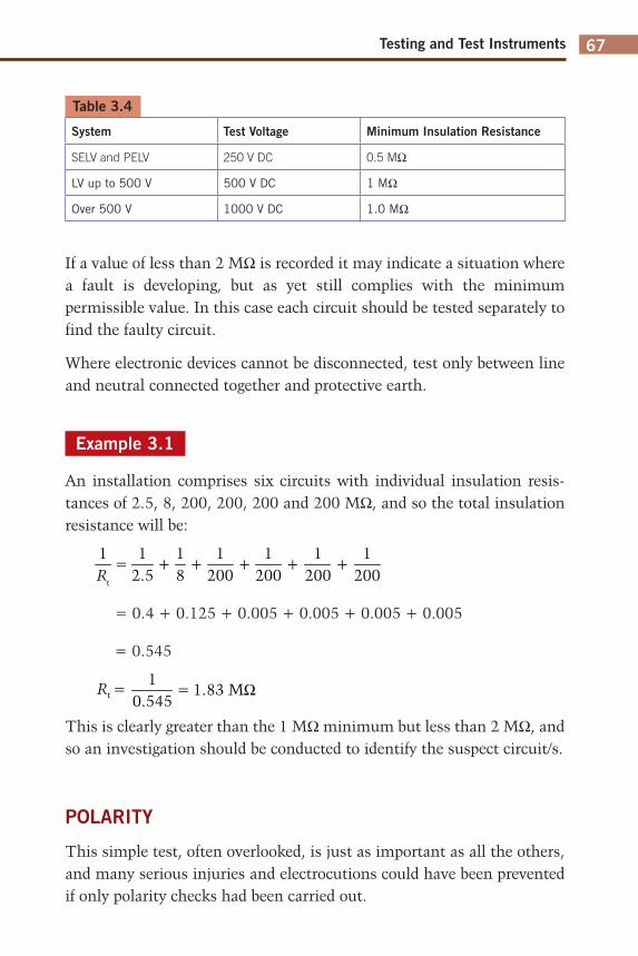
Testing and Test Instruments 67
Table 3.4
System Test Voltage Minimum Insulation Resistance
SELV and PELV 250 V DC 0.5 MΩ
LV up to 500 V 500 V DC 1 MΩ
Over 500 V 1000 V DC 1.0 MΩ
If a value of less than 2 MΩ is recorded it may indicate a situation where a fault is developing, but as yet still complies with the minimum permissible value. In this case each circuit should be tested separately to find the faulty circuit.
Where electronic devices cannot be disconnected, test only between line and neutral connected together and protective earth.
Example 3.1
An installation comprises six circuits with individual insulation resis-tances of 2.5, 8, 200, 200, 200 and 200 MΩ, and so the total insulation resistance will be:
12.5
1Rt
1200
1200
1200
1200
18
= + + + + +
= 0.4 + 0.125 + 0.005 + 0.005 + 0.005 + 0.005
= 0.545
1= 1.83 MΩ
0.545Rt =
This is clearly greater than the 1 MΩ minimum but less than 2 MΩ, and so an investigation should be conducted to identify the suspect circuit/s.
POLARITY
This simple test, often overlooked, is just as important as all the others, and many serious injuries and electrocutions could have been prevented if only polarity checks had been carried out.
Wiring Systems and Fault Finding68
The requirements are:
1. All fuses and single pole switches are in the line conductor.2. The centre contact of an Edison screw type lampholder is connected
to the line conductor (except E 14 and E 27, which are new types with an insulating thread material).
3. All socket outlets and similar accessories are correctly wired.
Although polarity is towards the end of the recommended test sequence, it would seem sensible, on lighting circuits, for example, to conduct this test at the same time as that for continuity of cpcs (Figure 3.11).
As discussed earlier, polarity on ring final circuit conductors is achieved simply by conducting the ring circuit test. For radial socket-outlet circuits, however, this is a little more difficult. The continuity of the cpc will have already been proved by linking line and cpc and measuring between the same terminals at each socket. Whilst a line–cpc reversal would not have shown, a line–neutral reversal would, as there would have been no reading at the socket in question. This would have been remedied, and so only line– cpc reversals need to be checked. This can be done by linking together line and neutral at the origin and testing between the same terminals at each socket. A line–cpc reversal will result in no reading at the socket in question.
When the supply is connected, it is important to check that the incoming supply is correct. This is done using an approved voltage indicator at the intake position or close to it. In the case of a three phase supply a phase sequence indicator would be used.
FIGURE 3.11 Lighting polarity.
®
— 1 o r ol © r © o r o o w\ o o ol
o o\
®
_l 1
H h E]
Temporary link
Switch wire cpc
Continuity of cpc
D D
Polarity (proved by operating switch)
Testing and Test Instruments 69
EARTH FAULT LOOP IMPEDANCE
This is very important but, sadly, poorly understood. So let us remind ourselves of the component parts of the earth fault loop path (Figure 3.12). Starting at the point of fault:
1. The cpc.2. The earthing conductor and earthing terminal.3. The return path via the earth for TT systems, and the metallic
return path in the case of TN-S or TN-C-S systems. In the latter case the metallic return is the PEN conductor.
4. The earthed neutral of the supply transformer.5. The transformer winding.6. The line conductor back to the point of fault.
FIGURE 3.12 Earth fault loop path.
Earth fault loop path L Protective device
o
Fault
cpc
Mass of earth
T.T Return path
Wiring Systems and Fault Finding70
Overcurrent protective devices must, under earth fault conditions, disconnect fast enough to reduce the risk of electric shock. This is achieved if the actual value of the earth fault loop impedance does not exceed the tabulated maximum values given in the IET Regulations.
The purpose of the test, therefore, is to determine the actual value of the loop impedance (Zs), for comparison with those maximum values, and it is conducted as follows:
1. Ensure that all main protective bonding conductors are in place.2. Connect the test instrument either by its BS 1363 plug, or the
‘flying leads’, to the line, neutral and earth terminals at the remote end of the circuit under test. (If a neutral is not available, e.g. in the case of a three-phase motor, connect the neutral probe to earth.)
3. Press to test and record the value indicated.
It must be understood that this instrument reading is not valid for direct comparison with the tabulated maximum values, as account must be taken of the ambient temperature at the time of test, and the maximum conductor operating temperature, both of which will have an effect on conductor resistance. Hence, the (R1 + R2) could be greater at the time of fault than at the time of test.
So, our measured value of Zs must be corrected to allow for these pos-sible increases in temperature occurring at a later date. This requires actually measuring the ambient temperature and applying factors in a formula.
Clearly, this method of correcting Zs is time consuming and unlikely to be commonly used. Hence, a rule of thumb method may be applied which simply requires that the measured value of Zs does not exceed 0.8 of the appropriate tabulated value. Table 3.5 gives the 0.8 values of tabulated loop impedance for direct comparison with measured values.
In effect, a loop impedance test places a line/earth fault on the installation, and if an RCD is present it may not be possible to conduct the test as the device will trip out each time the loop impedance tester button is pressed. Unless the instrument is of a type that has a built-in guard against such tripping, the value of Zs will have to be determined from measured values of Ze and (R1 + R2), and the 0.8 rule applied.
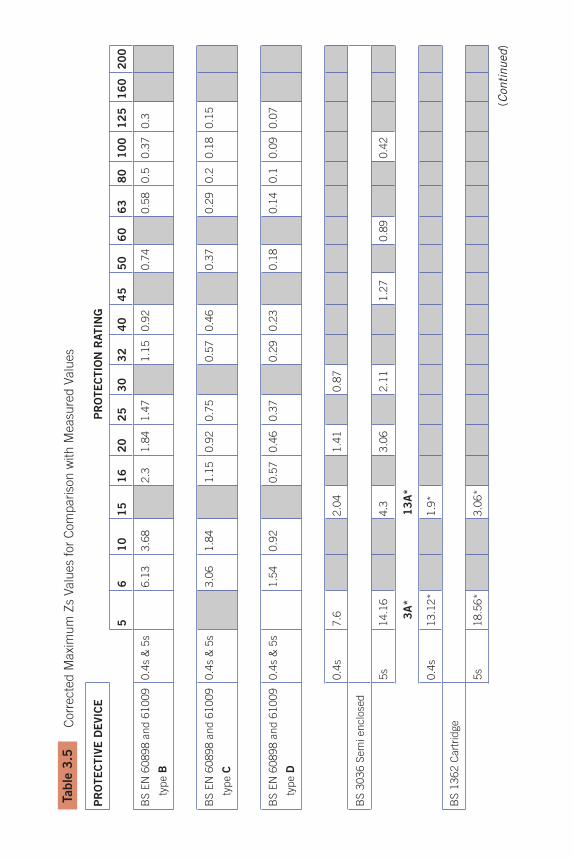
71
Table
3.5
C
orr
ecte
d M
axi
mu
m Z
s Valu
es
for
Com
pariso
n w
ith M
easu
red V
alu
es
PR
OTE
CTIV
E D
EVIC
EP
RO
TE
CTIO
N R
ATIN
G
56
10
15
16
20
25
30
32
40
45
50
60
63
80
10
01
25
16
02
00
BS E
N 6
0898 a
nd 6
1009
type B
0.4
s &
5s
6.1
33
.68
2.3
1.8
41
.47
1.1
50
.92
0.7
40
.58
0.5
0.3
70.3
BS
EN
60898 a
nd 6
1009
type C
0.4
s &
5s
3.0
61
.84
1.1
50
.92
0.7
50
.57
0.4
60
.37
0.2
90
.20.1
80.1
5
BS
EN
60898 a
nd 6
1009
type D
0.4
s &
5s
1.5
40
.92
0.5
70
.46
0.3
70
.29
0.2
30
.18
0.1
40
.10.0
90.0
7
0.4
s7
.62
.04
1.4
10
.87
BS
3036 S
em
i enclo
sed
5s
14
.16
4.3
3.0
62
.11
1.2
70
.89
0.4
2
3A
*1
3A
*
0.4
s1
3.1
2*
1.9
*
BS
1362 C
art
ridge
5s
18
.56
*3
.06
*
(Con
tinu
ed)
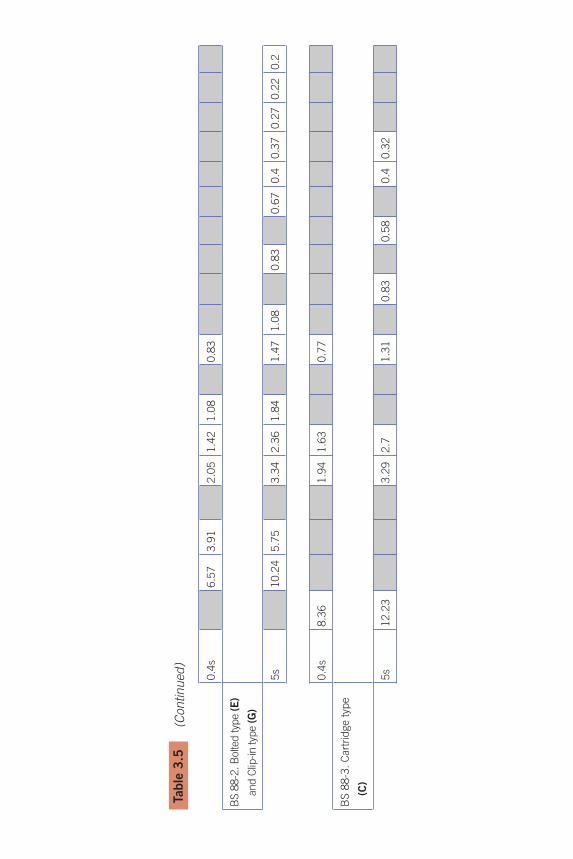
72
0.4
s6
.57
3.9
12
.05
1.4
21
.08
0.8
3
BS 8
8-2
. B
olted typ
e (E)
and C
lip-in typ
e (G
)
5s
10
.24
5.7
53
.34
2.3
61
.84
1.4
71
.08
0.8
30
.67
0.4
0.3
70.2
70.2
20.2
0.4
s8
.36
1.9
41
.63
0.7
7
BS
88-3
. C
art
ridge t
ype
(C)
5s
12
.23
3.2
92
.71
.31
0.8
30
.58
0.4
0.3
2
Table
3.5
(C
ontinu
ed
)
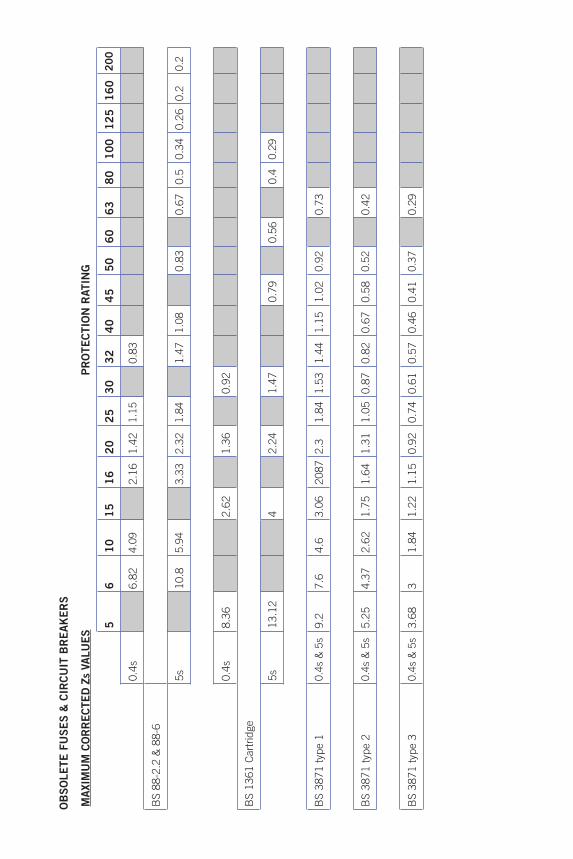
73
OB
SO
LE
TE
FU
SE
S &
CIR
CU
IT B
RE
AK
ER
S
MAXIM
UM
CO
RR
ECTED
Zs
VALU
ES
PR
OTE
CTIO
N R
ATIN
G
56
10
15
16
20
25
30
32
40
45
50
60
63
80
10
01
25
16
02
00
0.4
s6
.82
4.0
92
.16
1.4
21.1
50
.83
BS
88-2
.2 &
88-6
5s
10
.85.9
43
.33
2.3
21.8
41
.47
1.0
80
.83
0.6
70
.50.3
40.2
60.2
0.2
0.4
s8
.36
2.6
21
.36
0.9
2
BS
1361 C
art
ridge
5s
13
.12
42
.24
1.4
70
.79
0.5
60
.40.2
9
BS
3871 t
ype 1
0.4
s &
5s
9.2
7.6
4.6
3.0
62
08
72
.31
.84
1.5
31
.44
1.1
51
.02
0.9
20
.73
BS
3871 t
ype 2
0.4
s &
5s
5.2
54
.37
2.6
21
.75
1.6
41
.31
1.0
50
.87
0.8
20
.67
0.5
80.5
20
.42
BS
3871 t
ype 3
0.4
s &
5s
3.6
83
1.8
41
.22
1.1
50
.92
0.7
40
.61
0.5
70
.46
0.4
10.3
70
.29
Wiring Systems and Fault Finding74
Important Note
Never short out an RCD in order to conduct this test.
As a loop impedance test creates a high earth fault current, albeit for a short space of time, some lower rated circuit breakers may operate, resulting in the same situation as with an RCD, and Zs will have to be calculated. It is not really good practice temporarily to replace the circuit breaker with one of a higher rating.
External loop impedance Ze
The value of Ze is measured at the intake position on the supply side and with all main protective bonding conductors disconnected. Unless the installation can be isolated from the supply, this test should not be carried out, as a potential shock risk will exist with the supply on and the main bonding disconnected.
Prospective fault current
This would normally be carried out at the same time as the measurement for Ze using a PFC or PSCC (prospective short-circuit current) tester. If this value cannot be measured it must be ascertained by either enquiry or calculation.
Be sure to follow the instrument manufacturer’s instructions. Measure Ipf line to neutral, if three leads, place N/protective conductors on neutral bar (for typical instruments). Record highest reading and determine a value for three phase where Ipf (short circuit current) is approximately 2 � single-phase value.
EARTH ELECTRODE RESISTANCE
In many rural areas, the supply system is TT and hence reliance is placed on the general mass of earth for a return path under earth fault conditions. Connection to earth is made by an electrode, usually of the rod type, and preferably installed as shown in Figure 3.13.
Testing and Test Instruments 75
In order to determine the resistance of the earth return path, it is necessary to measure the resistance that the electrode has with earth. If we were to make such measurements at increasingly longer distances from the electrode, we would notice an increase in resistance up to about 2.5–3 m from the rod, after which no further increase in resistance would be noticed (Figure 3.14).
The maximum resistance recorded is the electrode resistance and the area that extends the 2.5–3 m beyond the electrode is known as the earth electrode resistance area.
There are two methods of making the measurement, one using a proprietary instrument and the other using a loop impedance tester.
Method 1: Usually where no AC supply is available
This method is based on the principle of the potential divider (Figure 3.15).
By varying the position of the slider the resistance at any point may be calculated from R = V/I.
FIGURE 3.13 Earth electrode installation.
Earthing conductor protected from corrosion and mechanical damage
Earth électrode
Wiring Systems and Fault Finding76
FIGURE 3.14 Earth electrode resistance area.
FIGURE 3.15 Potential divider.
Résistance increases up to approximately 2.5 m
Résistance area of électrode
No further increase in résistance
R Qs
/Y Slider
Résistance
Testing and Test Instruments 77
The earth electrode resistance test is conducted in a similar fashion, with the earth replacing the resistance and a potential electrode replacing the slider (Figure 3.16). In Figure 3.16 the earthing conductor to the electrode under test is temporarily disconnected.
The method of test is as follows:
1. Place the current electrode (C2) away from the electrode under test, approximately 10 times its length (i.e. 30 m for a 3 m rod).
2. Place the potential electrode mid way. 3. Connect test instrument as shown. 4. Record resistance value. 5. Move the potential electrode approximately 3 m either side of the
mid position, and record these two readings. 6. Take an average of these three readings (this is the earth electrode
resistance). 7. Determine the maximum deviation or difference of this average
from the three readings. 8. Express this deviation as a percentage of the average reading. 9. Multiply this percentage deviation by 1.2.10. Provided this value does not exceed a figure of 5% then the
accuracy of the measurement is considered acceptable.
FIGURE 3.16 Earth electrode test.
Potential électrode
15-25 m
Electrode under test
C1 L1 L2 C2
3m 3m Alternative-position^
V_ i )
15-25 m
Current électrode
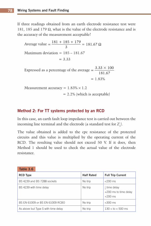
Wiring Systems and Fault Finding78
If three readings obtained from an earth electrode resistance test were 181, 185 and 179 Ω, what is the value of the electrode resistance and is the accuracy of the measurement acceptable?
Average value = 181.67 Ω3
181 + 185 + 179=
Maximum deviation = 185 – 181.67
= 3.33
Expressed as a percentage of the average 3.33 � 100
181.67=
= 1.83%
Measurement accuracy = 1.83% × 1.2
= 2.2% (which is acceptable)
Method 2: For TT systems protected by an RCD
In this case, an earth fault loop impedance test is carried out between the incoming line terminal and the electrode (a standard test for Ze).
The value obtained is added to the cpc resistance of the protected circuits and this value is multiplied by the operating current of the RCD. The resulting value should not exceed 50 V. If it does, then Method 1 should be used to check the actual value of the electrode resistance.
Table 3.6
RCD Type Half Rated Full Trip Current
BS 4239 and BS 7288 sockets No trip <200 ms
BS 4239 with time delay No trip 1
2 time delay
+200 ms to time delay
+200 ms
BS EN 61009 or BS EN 61009 RCBO No trip <300 ms
As above but Type S with time delay No trip 130 < to < 500 ms
Testing and Test Instruments 79
FUNCTIONAL TESTING
RCD/RCBO operation
Where RCDs/RCBOs are fitted, it is essential that they operate within set parameters. The RCD testers used are designed to do just this, and the basic tests required are as follows:
1. Set the test instrument to the rating of the RCD.2. Set the test instrument to half rated trip.3. Operate the instrument and the RCD should not trip.4. Set the instrument to deliver the full rated tripping current of the
RCD.5. Operate the instrument and the RCD should trip out in the
required time.
There seems to be a popular misconception regarding the ratings and uses of RCDs in that they are the panacea for all electrical ills and the only useful rating is 30 mA!!
Firstly, RCDs are not fail safe devices, they are electromechanical in operation and can malfunction, and secondly, RCDs are manufactured in ratings from 5 to 500 mA and have many uses. Table 3.7 illustrates RCD ratings and applications.
For 30 mA ratings, it is required that the RCD be injected with a current five times its operating current and the tripping time should not exceed 40 ms.
Where loop impedance values cannot be met, RCDs of an appropriate rating can be installed. Their rating can be determined from
IΔn = 50/Zs
where:
IΔn is the rated operating current of the device50 is the touch voltageZs is the measured loop impedance
All RCDs have a built-in test facility in the form of a test button. Operating this test facility creates an artificial out-of-balance condition that causes the device to trip. This only checks the mechanics of the tripping operation, it is not a substitute for the tests just discussed.
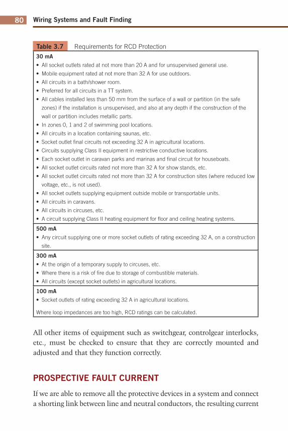
Wiring Systems and Fault Finding80
Table 3.7 Requirements for RCD Protection
30 mA
• All socket outlets rated at not more than 20 A and for unsupervised general use.
• Mobile equipment rated at not more than 32 A for use outdoors.
• All circuits in a bath/shower room.
• Preferred for all circuits in a TT system.
• All cables installed less than 50 mm from the surface of a wall or partition (in the safe
zones) if the installation is unsupervised, and also at any depth if the construction of the
wall or partition includes metallic parts.
• In zones 0, 1 and 2 of swimming pool locations.
• All circuits in a location containing saunas, etc.
• Socket outlet fi nal circuits not exceeding 32 A in agricultural locations.
• Circuits supplying Class II equipment in restrictive conductive locations.
• Each socket outlet in caravan parks and marinas and fi nal circuit for houseboats.
• All socket outlet circuits rated not more than 32 A for show stands, etc.
• All socket outlet circuits rated not more than 32 A for construction sites (where reduced low
voltage, etc., is not used).
• All socket outlets supplying equipment outside mobile or transportable units.
• All circuits in caravans.
• All circuits in circuses, etc.
• A circuit supplying Class II heating equipment for fl oor and ceiling heating systems.
500 mA
• Any circuit supplying one or more socket outlets of rating exceeding 32 A, on a construction
site.
300 mA
• At the origin of a temporary supply to circuses, etc.
• Where there is a risk of fi re due to storage of combustible materials.
• All circuits (except socket outlets) in agricultural locations.
100 mA
• Socket outlets of rating exceeding 32 A in agricultural locations.
Where loop impedances are too high, RCD ratings can be calculated.
All other items of equipment such as switchgear, controlgear interlocks, etc., must be checked to ensure that they are correctly mounted and adjusted and that they function correctly.
PROSPECTIVE FAULT CURRENT
If we are able to remove all the protective devices in a system and connect a shorting link between line and neutral conductors, the resulting current
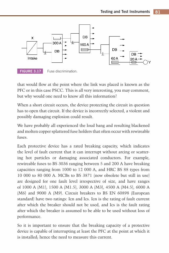
Testing and Test Instruments 81
that would flow at the point where the link was placed is known as the PFC or in this case PSCC. This is all very interesting, you may comment, but why would one need to know all this information?
When a short circuit occurs, the device protecting the circuit in question has to open that circuit. If the device is incorrectly selected, a violent and possibly damaging explosion could result.
We have probably all experienced the loud bang and resulting blackened and molten copper splattered fuse holders that often occur with rewireable fuses.
Each protective device has a rated breaking capacity, which indicates the level of fault current that it can interrupt without arcing or scatter-ing hot particles or damaging associated conductors. For example, rewireable fuses to BS 3036 ranging between 5 and 200 A have breaking capacities ranging from 1000 to 12 000 A, and HRC BS 88 types from 10 000 to 80 000 A. MCBs to BS 3871 (now obsolete but still in use) are designed for one fault level irrespective of size, and have ranges of 1000 A (M1), 1500 A (M1.5), 3000 A (M3), 4500 A (M4.5), 6000 A (M6) and 9000 A (M9). Circuit breakers to BS EN 60898 (European standard) have two ratings: Icn and Ics. Icn is the rating of fault current after which the breaker should not be used, and Ics is the fault rating after which the breaker is assumed to be able to be used without loss of performance.
So it is important to ensure that the breaking capacity of a protective device is capable of interrupting at least the PFC at the point at which it is installed; hence the need to measure this current.
FIGURE 3.17 Fuse discrimination.
■±-Intake
^ 3 -300 A
DB
±-DB
100A ^ 3 -
4b DB
60 A DB t
20 AF O Y
Wiring Systems and Fault Finding82
The type of instrument most commonly used is a dual device which also measures earth fault loop impedance. It is simply connected or plugged into the circuit close to the point of protection, a button pushed and the PFC value read.
It is not always necessary to test at every point at which a protective device is installed, if the breaking capacity of the lowest rated device in the circuit is greater than the PSCC at the origin. In Figure 3.17, clearly if the breaking capacity of the 20 A protective device at Y is greater than the PSCC at X, then there is no need to test at the other DBs as the protection there will have even greater breaking capacities than the 20 A device.
83
CHAPTER 4
Fault Finding
Important terms/topics covered in this chapter:
■ Signs and symptoms of faults■ Typical faults and their diagnosis
At the end of this chapter the reader should:
■ have an understanding of typical faults on a range of systems,■ know the correct approach to fault diagnosis.
Starting this chapter has been as difficult as finding a fault on a complex system. The old adage of ‘start at the beginning and finish at the end’ is all right for storytellers or authors of technical books, but is not always sensible for fault finders! Perhaps it would be wise to begin by determining what exactly a fault is.
A fault is probably best defined as a disturbance in an electrical system of such magnitude as to cause a malfunction of that system. It must be remembered, of course, that such disturbances may be the secondary effects of mechanical damage or equipment failure. Actual electrical faults, or should one say faults that are caused by ‘electricity’, are rare and are confined in the main to bad design and/or installation or deterioration and ageing.
However, all of this still does little to indicate where to begin looking for a fault. Only experience will allow one to pinpoint the exact seat of a breakdown, but a logical approach to fault finding will save a great deal of time and frustration.
SIGNS AND SYMPTOMS
Always look for tell-tale signs that may indicate what kind of fault has caused the system breakdown. If possible, ask persons present to describe
Wiring Systems and Fault Finding84
the events that led up to the fault. For example, inspection of a rewireable fuse may reveal one of the conditions shown in Figures 4.1 and 4.2.
The IET Wiring Regulations define overload and short-circuit current as follows:
■ Overload current: An overcurrent occurring in a circuit which is electrically sound.
■ Short-circuit current: An overcurrent resulting from a fault of negligible impedance between live conductors having a difference in potential under normal operating conditions.
It is likely that other personnel will have replaced fuses or reset circuit breakers to no avail before you, the tester, is called in. In these circumstances they will be in a position to indicate that protective devices operate immediately or after a delay. This at least will give some clue to the type of fault.
Let us now consider typical faults on some of the systems already discussed in this book, and endeavour to suggest some solutions.
Remember, however, that it is impossible to catalogue every fault and its cause that may occur in every system.
FIGURE 4.1
FIGURE 4.2
Fuse holder
• •
_j/^~ Overload or ageing
Fuse holder y
Short circuit
Fault Finding 85
Diagnostic flow-charts have been included for some of the following faults.
RING AND RADIAL SOCKET OUTLET CIRCUITS
Reported fault
‘My fuse/circuit breaker blows at odd unspecified times during the day, with no particular appliance plugged into any particular socket.’
Diagnosis
1. This could be incorrect fusing, but that is unlikely because then the fault would always have been present. It is probably an insulation breakdown.
2. Conduct an insulation resistance test (remember to remove all appliances). If the reading is low, then:
3. Go to the centre of the circuit and disconnect the socket; disconnect the ends in the fuse board if the circuit is a ring; and test in both directions.
4. Probably only one side will indicate a fault, so subdivide. Keep testing and subdividing until the faulty cable section or socket is located (Figure 4.3).
New ring fi nal circuit installations
In Chapter 3 three methods are described for testing the continuity of the final conductors. The purpose is to locate interconnections in the ring. Should such an interconnection prove to exist, its position in the ring must be located. Methods 1 and 2 will indicate a fault, but location is achieved by systematically removing sockets to find the interconnection. Method 3 will give an indication of the location of the fault because tests on sockets nearest to the fuse board will give similar readings, whereas those beyond the interconnection will be considerably different.
Wiring Systems and Fault Finding86
RADIAL CIRCUITS FEEDING FIXED EQUIPMENT
Reported fault
‘Every time I start my hydraulic press, the fuse blows in the board.’
Diagnosis
1. This is probably a fault on the press motor windings or the starter. A supply cable fault would normally operate the protection without an attempt to start the motor.
2. Check the starter for obvious signs of damage, burning, etc. If it seems all right, then:
3. Do an insulation resistance test on the motor windings (Figure 4.4).
Reported fault
‘The circuit breaker that protects my roof extraction fan has tripped out and will not reset even with the fan switched off.’
Diagnosis
This is almost certainly a cable fault. Do an insulation resistance test. If a fault is indicated, start looking!
FIGURE 4.3 Socket outlet fault fl ow-chart.
IR test on circuit cable
NotOK
Break circuit down to locate fault
Rectify fault
-►OK Jï\
y Unpiug/switch off casual
appliances. Leave permanent appliances connected
1 Fault does not
reappear
1 Check casual
appliances
—► Fault remains
y Check
permanent appliances
Fault Finding 87
CABLE FAULT LOCATION
The comment ‘start looking’ in the last example is quite acceptable for shortish, accessible cable runs and where some sign of damage is evident. However, for longer, hidden cable routes, especially under ground, visual location is impossible. In these instances special tests must be applied, such as the following.
Murray loop test
This test and its variations are based on the principle of the Wheatstone bridge. It is used for the location of short-circuit faults. In Figure 4.5, when the variable resistances are adjusted such that the reading on the ammeter is zero, it will be found that
A/B = C/D
Let us now replace resistors C and D with the same cores of a faulty cable (Figure 4.6). The ratios will be the same, as resistance is proportional to length. A link is placed between a sound core and a faulty core. It will be seen that now C is replaced by L + (L – X), and D by X, so that a greater
FIGURE 4.4 Fixed equipment fault fl ow chart.
IR test on circuit cable -►NotOK-
OK
Check fan -►NotOK-
OK
\ Probable
MCB failure
^ Locate and rectify
cable fault
^ Replace or repair
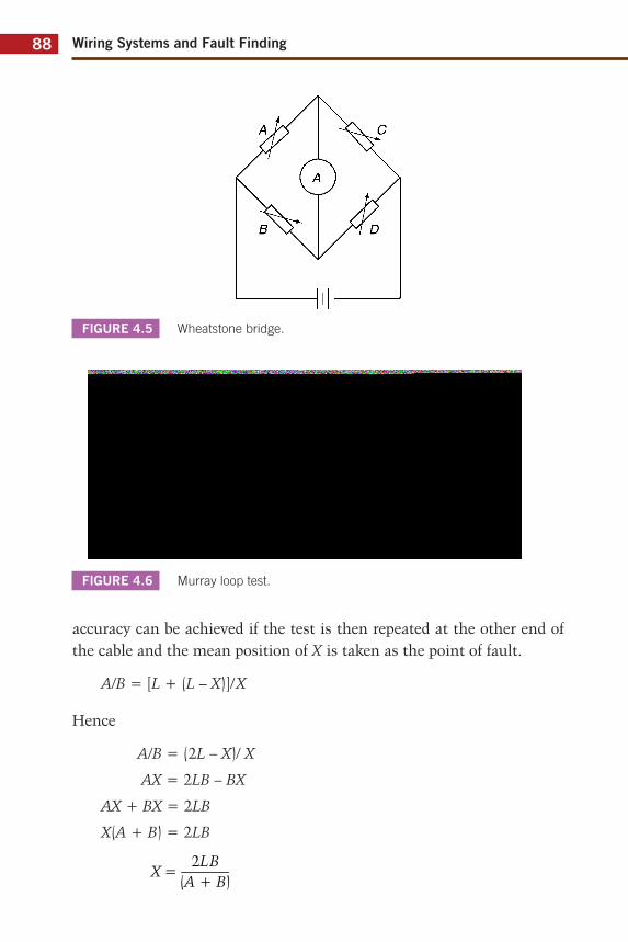
Wiring Systems and Fault Finding88
accuracy can be achieved if the test is then repeated at the other end of the cable and the mean position of X is taken as the point of fault.
A/B = [L + (L – X)]/X
Hence
A/B = (2L – X)/ X
AX = 2LB – BX
AX + BX = 2LB
X(A + B) = 2LB
2LBX =
(A + B)
FIGURE 4.5 Wheatstone bridge.
FIGURE 4.6 Murray loop test.
D
Sound core
Link
Fault Finding 89
Variable resistors A and B are usually incorporated in a single bridge instrument, and the resistances are adjusted for a zero reading.
EMERGENCY LIGHTING
There is not a lot to go wrong with these systems other than the cable faults and internal failure of the unit. Cable faults are located in the way previously described; however, do not conduct insulation resistance tests with the unit still connected, or the internal electronic circuitry may be damaged.
Individual units have LEDs that indicate a healthy state of charge. If this is out,
1. Check the mains supply. If it is all right, then:2. Check the output of the charging unit at the battery terminals. If
this is all right, check the battery separately.
If the LED is lit but the emergency light does not function when the mains supply is removed, check the lamps. If these are functioning, the circuitry is probably faulty.
SECURITY AND FIRE ALARM SYSTEMS
Fire alarm systems have to be inspected at regular intervals and hence tend to be very reliable. The most common faults in such systems are false operation of heat or smoke detectors, perhaps owing to a change in the use of the protected area since they were first installed, or a break in the sensor cable. As the continuity of these cables is monitored, any fault will bring up a fault condition on the main panel. Simple continuity tests on cable between sensors should reveal the broken section.
Security systems are somewhat similar in that faults on cables or sensors will bring up an alarm condition on the main panel. Remove the ends of the zone in question and insert a shorting link. If the alarm still activates when switched on, a fault in the internal circuitry is indicated. If not, start at the middle of a zone and work back to the panel, similar to the procedure used on ring/radial circuits, until the faulty cable or sensor is found.
Wiring Systems and Fault Finding90
CALL SYSTEMS
The faults on these systems, once again, are broadly similar to those on alarm systems.
Reported fault
‘The patient in room 42 pushes the call button but nothing happens.’
Diagnosis
This is either a faulty push-button, a break in the cable, or a defective relay or electronic component. Trial and error is the rule here: check out the simple and obvious first before taking the control panel apart (Figure 4.7).
FIGURE 4.7 Call system fault fl ow chart.
Check push-button ► Not OK — ► Replace or repair
OK
Short out button, check cable
continuity at panel end
T OK
\
Investigate relay or electronics if
possible
-► Not OK Replace or repair
Fault Finding 91
CENTRAL HEATING SYSTEMS
The most difficult faults to locate are those that occur during the commissioning of a newly installed system, and are almost always due to incorrect wiring. Naturally, not all the faults that could occur on all the available systems can be detailed, but there are one or two common mistakes that are worth mentioning:
1. The CH is selected but the HW comes on, and vice versa. This is simply a reversal of the CH and HW feeds in the programmer.
2. On a mid-position valve system, a reversal of the leads to the demand and satisfy terminals in the cylinder thermostat will cause various incorrect sequences depending on which heating options have been chosen.
On one occasion, the author installed the control wiring for a CH system, and was perplexed when the room thermostat operated the HW and the cylinder thermostat operated the CH. Much tearing of hair followed, as the system wiring proved to be correct. Some time later it was discovered that the DIY householder had installed the mid-position valve back-to-front.
With existing systems, faults tend to be confined to equipment failure such as defective programmers, valves and pumps. Once again it must be stressed that fault location on such systems is eased considerably when the system is fully understood, and this generally comes with experience.
MOTOR STARTER CIRCUITS
The usual cable faults we have already discussed must of course be considered, but faults in the starter itself are usually confined to coil failure or contact deterioration.
Coil failure
If this should occur the motor will not start, for the obvious reason that the control circuit is defective.
Wiring Systems and Fault Finding92
Reported fault
‘Everything was all right this morning – the motor was running – but this afternoon everything just stopped, and will not start up again.’
Diagnosis
Could be operation of circuit protection, coil failure or overload operation due to a motor fault or excessive mechanical loading.
1. Check overloads. If they have operated, carry out insulation resistance test on motor windings. If all OK, then:
2. Check circuit protection. If all OK, then fault is probably coil failure. This can be verified by testing the coil, or holding in the contactor manually (Figure 4.8).
Contact deterioration
Here is one of the few genuine faults caused by the effects of ‘electricity’. Over time, constant operation with its attendant arcing will burn and pit the surface of contacts. This can lead to poor connection between the faces, or even the complete destruction of the contacts.
FIGURE 4.8 Motor circuit fault fl ow chart.
Check circuit protection
f NotOK
IR test on circuit cable
NotOK
OK
Locate and rectify cable fault
OK
Check motor
T OK
NotOK - Repair/replace
Check starter
Overloads Connections Coil
Fault Finding 93
Reported fault
‘We shut down the conveyor for lunch, and when we try to start it up again, it only works if we keep the start button in.’
Diagnosis
1. This is clearly a ‘hold-on’ circuit fault. The coil must be OK or the conveyor would not work.
2. Check the continuity across the hold-on contacts with the contactor depressed manually (supply isolated of course). If open circuit is found, strip the contactor and investigate.
Protection faults
Other causes of motor circuit failure often result from incorrect protection – fuses, MCBs or overloads – or incorrect reconnection after motor replacement.
Motors may take as much as eight times their normal rated current on starting. If the protection is of the wrong type or size, or is set incorrectly, it will operate.
Fuses
Use a motor rated fuse, usually BS 88. These are easily recognizable, as the rating has a prefix M (e.g. M20 is a 20 A motor rated fuse). They are designed to cater for high starting currents.
MCBs/CBs
These range from the now obsolete BS 3871 types 1, 2 and 3 to the latest BS EN 60898 types A, B, C and D. Types 1, 2, A and B are usually too sensitive to handle starting currents, so types 3, C and D are preferred.
Overloads
These are adjustable and their ratings must be suitable for the full load of the motor. Ensure that the overload has been selected to the correct rating.
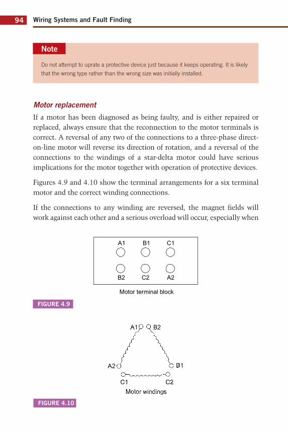
Wiring Systems and Fault Finding94
Note
Do not attempt to uprate a protective device just because it keeps operating. It is likely
that the wrong type rather than the wrong size was initially installed.
Motor replacement
If a motor has been diagnosed as being faulty, and is either repaired or replaced, always ensure that the reconnection to the motor terminals is correct. A reversal of any two of the connections to a three-phase direct-on-line motor will reverse its direction of rotation, and a reversal of the connections to the windings of a star-delta motor could have serious implications for the motor together with operation of protective devices.
Figures 4.9 and 4.10 show the terminal arrangements for a six terminal motor and the correct winding connections.
If the connections to any winding are reversed, the magnet fields will work against each other and a serious overload will occur, especially when
FIGURE 4.9
FIGURE 4.10
Motor windings
Fault Finding 95
the starter changes the motor windings to the delta configuration. For example, never allow A2 to be connected to B2 and A1 to C1.
CONCLUSION AND A CAUTIONARY TALE
Finally, it must be reiterated that successful and efficient fault finding has its basis in experience. However, for the beginner, use a logical and methodical approach, ask questions of the customer or client, and use some common sense. This in itself will often provide the clues for the diagnosis of system failure.
Once upon a time there was a young electrical apprentice (who shall remain nameless), who was doing a little wiring job (not private, of course). The customer asked the apprentice, while he was there, to investigate whether a cracked socket needed replacing. Of course he agreed to (thinking: ‘extras!’), and proceeded to undo the socket without isolating. There was a pop and a flash and the ring circuit fuse operated. ‘Silly me,’ he thought, ‘I’ll just repair the fuse, I must have shorted something out in the socket.’ ‘Hold on,’ thought he, ‘do this properly: never replace a fuse until the circuit has been checked first.’
An insulation resistance test seemed to be the order of the day, so naturally all appliances were removed from the ring and the test applied. It showed a line neutral short circuit. ‘Oh! bother’ (or some such expletive), he muttered, ‘Where do I start?’
Unfortunately the ring circuit was wired in the form of junction boxes in the upstairs floor void with single drops down to each socket. Splitting the ring meant gaining access to those JBs. Needless to say there were fitted carpets and tongued and grooved floorboards, and no access traps.
Five hours later, with carpets and floorboards up everywhere and a puzzled customer who did not understand such an upheaval to replace a cracked socket, the faulty drop was found. The apprentice ran downstairs but could not immediately find the associated socket outlet. It was there of course, in a cupboard, and next to it was a fridge with a door like a cupboard door, and naturally the fridge was plugged into the socket. ‘Heavens above!’ and ‘flip me’ said the apprentice, ‘I wish I had asked the

Wiring Systems and Fault Finding96
customer if there were any appliances I had missed. Worse than that, how do I explain this one away?’ Well, needless to say, he did, using the most impressive technical jargon, and vowed never to make the same mistake again.
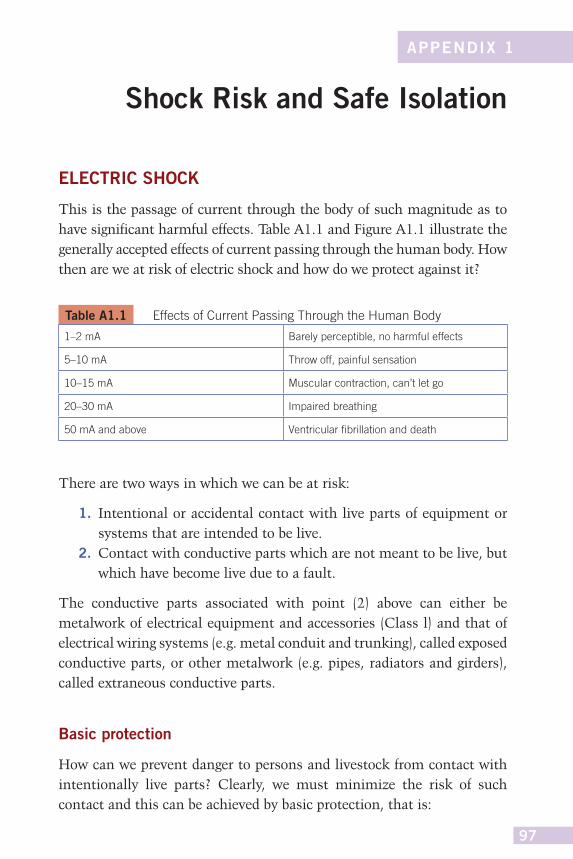
97
APPENDIX 1
Shock Risk and Safe Isolation
ELECTRIC SHOCK
This is the passage of current through the body of such magnitude as to have significant harmful effects. Table A1.1 and Figure A1.1 illustrate the generally accepted effects of current passing through the human body. How then are we at risk of electric shock and how do we protect against it?
Table A1.1 Effects of Current Passing Through the Human Body
1–2 mA Barely perceptible, no harmful effects
5–10 mA Throw off, painful sensation
10–15 mA Muscular contraction, can’t let go
20–30 mA Impaired breathing
50 mA and above Ventricular fi brillation and death
There are two ways in which we can be at risk:
1. Intentional or accidental contact with live parts of equipment or systems that are intended to be live.
2. Contact with conductive parts which are not meant to be live, but which have become live due to a fault.
The conductive parts associated with point (2) above can either be metalwork of electrical equipment and accessories (Class l) and that of electrical wiring systems (e.g. metal conduit and trunking), called exposed conductive parts, or other metalwork (e.g. pipes, radiators and girders), called extraneous conductive parts.
Basic protection
How can we prevent danger to persons and livestock from contact with intentionally live parts? Clearly, we must minimize the risk of such contact and this can be achieved by basic protection, that is:

Wiring Systems and Fault Finding98
FIGURE A1.1 Shock levels.
■ insulating any live parts■ ensuring any uninsulated live parts are housed in suitable enclosures
and/or are behind barriers.
1-2 mA
i 5-1 OmA
10-15 mA 20-30 mA
50 mA and above
Appendix 1: Shock Risk and Safe Isolation 99
The use of a residual current device (RCD) cannot prevent contact with live parts, but it can be used as an addition to any of the other measures taken, provided that its rating, In, is 30 mA or less and has an operating time of not more than 40 ms at an operating current of ILn × 5.
It should be noted that RCDs must not be used as the sole means of protection.
Fault protection
How can we protect against shock from contact with unintentionally live, exposed or extraneous conductive parts whilst touching earth, or from contact between live exposed and/or extraneous conductive parts? The most common method is by protective earthing, in case of fault and protective equipotential bonding and automatic disconnection in case of a fault.
All extraneous conductive parts are joined together with a main protective bonding conductor and connected to the main earthing terminal, and all exposed conductive parts are connected to the main earthing terminal by the circuit protective conductors. Add to this, overcurrent protection that will operate fast enough when a fault occurs and the risk of severe electric shock is significantly reduced.
What is earth and why and how we connect to it?
The thin layer of material which covers our planet – rock, clay, chalk or whatever – is what we in the world of electricity refer to as earth. So, why do we need to connect anything to it? After all, it is not as if earth is a good conductor.
It might be wise at this stage to investigate potential difference (PD). A PD is exactly what it says it is: a difference in potential (volts). In this way, two conductors having PDs of, say, 20 and 26 V have a PD between them of 26 – 20 = 6 V. The original PDs (i.e. 20 and 26 V) are the PDs between 20 V and 0 V and 26 V and 0 V. So where does this 0 V or zero potential come from? The simple answer is, in our case, the earth. The definition of earth is, therefore, the conductive mass of earth, whose electric potential at any point is conventionally taken as zero.

Wiring Systems and Fault Finding100
Thus, if we connect a voltmeter between a live part (e.g. the line conductor of a socket outlet) and earth, we may read 230 V; the conductor is at 230 V and the earth at zero. The earth provides a path to complete the circuit. We would measure nothing at all if we connected our voltmeter between, say, the positive 12 V terminal of a car battery and earth, as in this case the earth plays no part in any circuit.
Figure A1.2 illustrates this difference.
FIGURE A1.2 (a) Earth return path, (b) No earth return path.
230 V
One phase of supply transformer
Earth 0V
(a)
12V
g
> »
(b)
Appendix 1: Shock Risk and Safe Isolation 101
So, a person in an installation touching a live part whilst standing on the earth would take the place of the voltmeter and could suffer a severe electric shock. Remember that the accepted lethal level of shock current passing through a person is only 50 mA or 1/20 A.
The same situation would arise if the person were touching a faulty appliance and a gas or water pipe (Figure A1.3).
One method of providing some measure of protection against these effects is, as we have seen, to join together (bond) all metallic parts and connect them to earth. This ensures that all metalwork in a healthy installation is at or near 0 V and, under fault conditions, all metalwork will rise to a similar potential. So, simultaneous contact with two such metal parts would not result in a dangerous shock, as there would be no significant PD between them.
Unfortunately, as mentioned, earth itself is not a good conductor, unless it is very wet. Therefore, it presents a high resistance to the flow of fault current. This resistance is usually enough to restrict fault current to a
FIGURE A1.3 Shock path.
Wiring Systems and Fault Finding102
level well below that of the rating of the protective device, leaving a faulty circuit uninterrupted. Clearly, this is an unhealthy situation.
In all but the most rural areas, consumers can connect to a metallic earth return conductor, which is ultimately connected to the earthed neutral of the supply. This, of course, presents a low-resistance path for fault currents to operate the protection.
In summary, connecting metalwork to earth places that metal at or near zero potential and bonding between metallic parts puts such parts at a similar potential even under fault conditions. Add to this a low-resistance earth fault return path, which will enable the circuit protection to operate very fast, and we have significantly reduced the risk of electric shock.
We can see from this how important it is to check that equipment earth-ing is satisfactory and that there is no damage to conductor insulation.
SAFE ISOLATION OF SUPPLIES
Before any work is undertaken on low-voltage (50–1000 V AC) installa-tions, supplies should be isolated and proved dead; the procedure is as follows:
1. Identify the circuit or item to be worked on.2. Switch off/isolate and lock off or place warning notices if locking is
not available.3. Select a suitable approved voltage indicator and check that it works,
on a known supply.4. Test that the circuit or equipment is dead using the tester.5. Recheck the tester on the known supply again.
Never assume or take someone else’s word that supplies are dead and safe to work on. Always check for yourself.
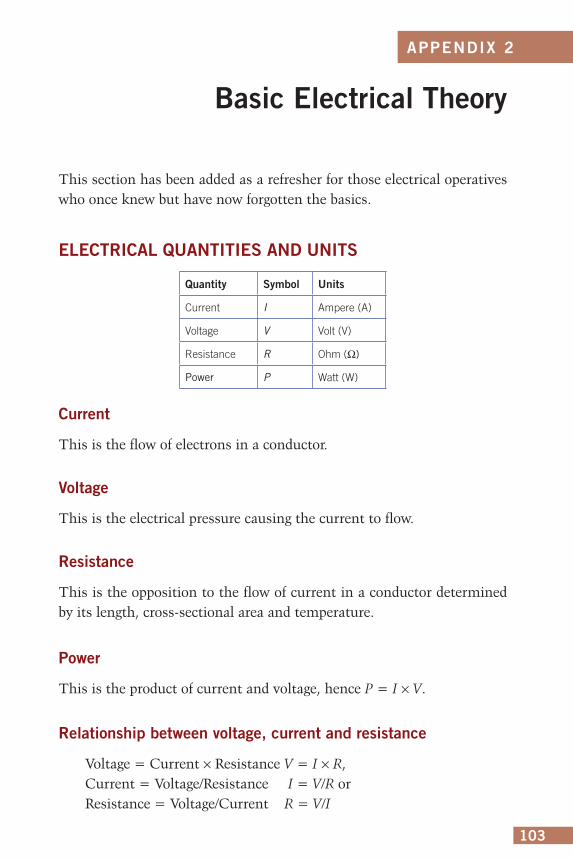
103
APPENDIX 2
Basic Electrical Theory
This section has been added as a refresher for those electrical operatives who once knew but have now forgotten the basics.
ELECTRICAL QUANTITIES AND UNITS
Quantity Symbol Units
Current I Ampere (A)
Voltage V Volt (V)
Resistance R Ohm (Ω)
Power P Watt (W)
Current
This is the flow of electrons in a conductor.
Voltage
This is the electrical pressure causing the current to flow.
Resistance
This is the opposition to the flow of current in a conductor determined by its length, cross-sectional area and temperature.
Power
This is the product of current and voltage, hence P = I × V.
Relationship between voltage, current and resistance
Voltage = Current × Resistance V = I × R,Current = Voltage/Resistance I = V/R orResistance = Voltage/Current R = V/I
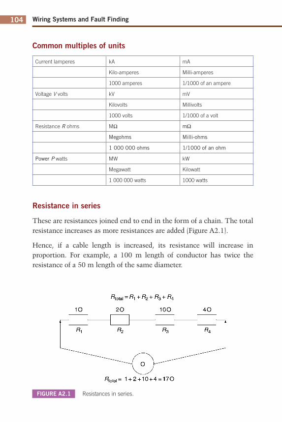
Wiring Systems and Fault Finding104
Common multiples of units
Current lamperes kA mA
Kilo-amperes Milli-amperes
1000 amperes 1/1000 of an ampere
Voltage V volts kV mV
Kilovolts Millivolts
1000 volts 1/1000 of a volt
Resistance R ohms MΩ mΩ
Megohms Milli-ohms
1 000 000 ohms 1/1000 of an ohm
Power P watts MW kW
Megawatt Kilowatt
1 000 000 watts 1000 watts
Resistance in series
These are resistances joined end to end in the form of a chain. The total resistance increases as more resistances are added (Figure A2.1).
Hence, if a cable length is increased, its resistance will increase in proportion. For example, a 100 m length of conductor has twice the resistance of a 50 m length of the same diameter.
FIGURE A2.1 Resistances in series.
^total - ^1 + ^2 + ^3 + ^4
10
* 1
2 0
R2
100
* 3
4 0
R4
fîtotal= 1 + 2 + 1 0 + 4 = 1 7 0
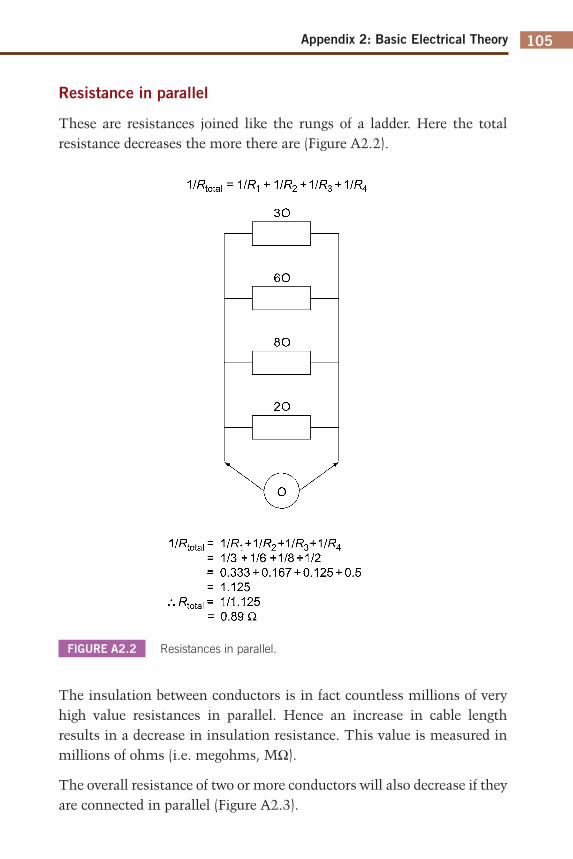
Appendix 2: Basic Electrical Theory 105
FIGURE A2.2 Resistances in parallel.
Resistance in parallel
These are resistances joined like the rungs of a ladder. Here the total resistance decreases the more there are (Figure A2.2).
The insulation between conductors is in fact countless millions of very high value resistances in parallel. Hence an increase in cable length results in a decrease in insulation resistance. This value is measured in millions of ohms (i.e. megohms, MΩ).
The overall resistance of two or more conductors will also decrease if they are connected in parallel (Figure A2.3).
1/Rtota, = 1//?! + 1/R2 + 1/R3 + 1//?4
30
60
80
2 0
1/Rtota,= MR^ + MR2+MR3+MR4 = 1/3+1/6+1/8 + 1/2 = 0.333 + 0.167 + 0.125 + 0.5 = 1.125
1/1.125 0.89 Q
notai "
Wiring Systems and Fault Finding106
The total resistance will be half of either one and would be the same as the resistance of a 2 mm2 conductor. Hence resistance decreases if conductor cross-sectional area increases.
Example A2.1
If the resistance of a 1.0 mm2 conductor is 19.5 mΩ/m, what would be the resistance of:
1. 85 m of 1.0 mm2 conductor2. 1 m of 6.0 mm2 conductor3. 25 m of 4.0 mm2 conductor4. 12 m of 0.75 mm2 conductor.
Answers
1. 1.0 mm2 is 19.5 mΩ/m, so, 85 m would be 19.5 × 85/1000 = 1.65 Ω
2. A 6.0 mm2 conductor would have a resistance 6 times less than a 1.0 mm2 conductor, i.e. 19.5/6 = 3.25 mΩ
3. 25 m of 4.0 mm2 would be 19.5 × 25/4 × 1000 = 0.12 Ω4. 19.5 mΩ/m = 1.5 (the ratio of 0.75 mm2 to 1.00 mm2 conductor)
× 12 m = 0.351 Ω.
POWER, CURRENT AND VOLTAGE
As we have already seen, at a basic level, power = current × voltage, or P = I × V. However, two other formulae can be produced: P = I2 × R and P = V2/R. Here are some examples of how these may be used.
FIGURE A2.3 Conductors in parallel.
1.0 mm2
1.0 mm2
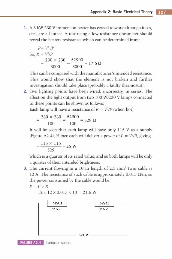
Appendix 2: Basic Electrical Theory 107
1. A 3 kW 230 V immersion heater has ceased to work although fuses, etc., are all intact. A test using a low-resistance ohmmeter should reveal the heaters resistance, which can be determined from:
P= V2 /PSo, R = V2/P
230 � 23017.6 Ω
3000
52900
3000= ==
This can be compared with the manufacturer’s intended resistance. This would show that the element is not broken and further investigation should take place (probably a faulty thermostat).
2. Two lighting points have been wired, incorrectly, in series. The effect on the light output from two 100 W/230 V lamps connected to these points can be shown as follows:Each lamp will have a resistance of R = V2/P (when hot)
230 � 230529 Ω
100
52900
100= ==
It will be seen that each lamp will have only 115 V as a supply (Figure A2.4). Hence each will deliver a power of P = V2/R, giving
115 � 11525 W
529==
which is a quarter of its rated value, and so both lamps will be only a quarter of their intended brightness.
3. The current flowing in a 10 m length of 2.5 mm2 twin cable is 12 A. The resistance of such cable is approximately 0.015 Ω/m, so the power consumed by the cable would be:P = I2 × R = 12 × 12 × 0.015 × 10 = 21.6 W
FIGURE A2.4 Lamps in series.
529 Q 529 a
115V 115V
230 V
109
APPENDIX 3
Solutions
QUIZ CONTROLLER (CHAPTER 1)
Figure A3.1 shows a solution. Any contestant pushing his/her button energizes their corresponding relay, which is held on via contacts RA1, RB1 or RC1. Two sets of N/C contacts, located in each of the other contestants’ circuits, will open, rendering those circuits inoperative. The system is returned to normal when the reset button is pushed, de-energizing the held-on relay.
FIGURE A3.1
FIGURE A3.2 Exercise 1a
FIGURE A3.3 Exercise 1b
Reset
Supply
B
RA3
RB3
RC
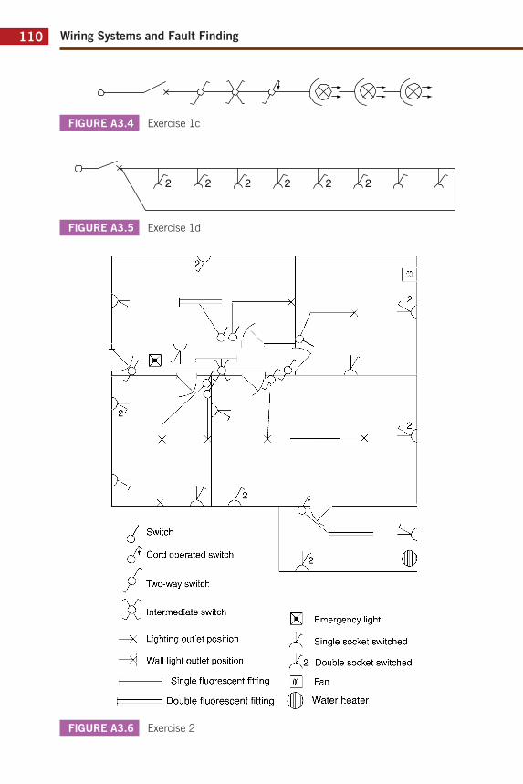
Wiring Systems and Fault Finding110
FIGURE A3.4 Exercise 1c
FIGURE A3.5 Exercise 1d
FIGURE A3.6 Exercise 2
J Switch
çV Cord operated switch
Two-way switch
Ç\ Intermediate switch
—X Lighting outlet position
—X| Wall light outlet position
| 1 Single fluorescent fitting
I 1 Double fluorescent fitting
IXI Emergency light
f\ Single socket switched
f\2 Double socket switched
[¥| Fan
Water heater
AAccelerator, 45Approved test lamps, 55–6Approximate maximum demand
(AMD), 28
BBand I circuits, 40Band II circuits, 40Basic electrical theory, 101–5
electrical quantities and units, 101–4power, current and voltage, 104–5
Basic protection, 95–7Block diagrams, 5BS EN 60617, 24
symbols, 1–4
CCable fault location, 85–7
Murray loop test, 85–7, 86Wheatstone bridge, 86
Calibration, 56–7Call systems, 40, 41, 88
fault flowchart, 88Care of instruments, 56–7Central heating systems, 43–8, 89
fully pumped system, 46–8, 47gravity primary and pumped heating,
46internal connections of mid-position
valve, 48pumped CH and gravity HW, 45–6
‘Check boxes,’ 57Circuit convention, 9Circuit diagrams, 5–6
construction and interpretation, 9–12contactor and relay conventions, 10electronic valet, 9–12, 10quiz controller, 12security system and intake arrangement
for domestic installation, 5two-way lighting system, 6
Closed-circuit system, 37–9Common multiples of units, 102
Conductors:in parallel, 104
Connection diagram see Wiring diagramContinuity:
of protective conductors, 57–60ring final circuit conductors, 60–5
Current, 101, 104–5Current loading, 28
DDiagrams, 1–21
block diagram, 5BS EN 60617 symbols, 1–4circuit convention, 9circuit or schematic diagrams, 5–6constructing and interpreting circuit
diagrams, 9–12heating and ventilation system, 12–14interconnection diagrams, 5programmable logic controllers, 16–21relay logic, 14–16schematic and wiring diagrams, 8wiring or connection diagrams, 6–9
Direct-on-line (DOL) starter, 41–2single phase, 42three phase, 42
Distribution boards (DB), 28Distribution network operators (DNO),
25Distribution systems, 25–32
block type, 28floor plan, 30garage/workshop floor plan, 32industrial installation layout, 27interconnection type, 29isometric drawing for garage/workshop,
31radial lighting circuit, 26ring final circuit, 27
EEarth, 97–100
earth return path, no earth return path, 98
111
Index
112 Index
Earth electrode resistance, 72–6earth electrode installation, 73earth electrode resistance area, 74earth electrode test, 75method 1: where no AC supply is
available, 73–6method 2: for TT systems protected by
an RCD, 76potential driver, 74
Earth fault loop impedance, 69–72earth fault loop path, 69external loop impedance, 72prospective fault current, 72values of loop impedance for
comparison with test readings, 71Earth loop impedance (ELI), 28Electric shock, 95Electrical quantities and units, 101–4
common multiples of units, 102conductors in parallel, 104current, 101power, 101relationship between voltage, current
and resistance, 101resistance, 101resistance in parallel, 103resistance in series, 102voltage, 101
Emergency lighting, 32–6, 87connection diagram details for garage/
workshop, 33connection diagram for part of
ventilation scheme, 34maintained system, 32–5, 35non-maintained system, 35–6
Exposed conductive parts, 95External loop impedance, 72Extra low-voltage (ELV), 40Extra low-voltage lighting, 48–9
block diagram, 49Extraneous conductive parts, 95
FFault, 81Fault finding, 81–94
cable fault location, 85–7call systems, 88central heating systems, 89emergency lighting, 87motor starter circuits, 89–93radial circuits feeding fixed equipment,
84–5ring and radial socket outlet circuits,
83–4
security and fire alarm systems, 87signs and symptoms, 81–3
Fault protection, 97Fire alarm systems, 36–9, 38, 87
block diagram, 36closed-circuit system, 37–9, 38open circuit system, 36–7
Functional testing, 77–8RCD/RCBO operation, 77–8requirements for RCD protection, 78
G‘Gates,’ 15
HHeating and ventilation system, 12–14
schematic diagram, 13HSE Guidance Note GS38 ‘Electrical
test equipment for use by electricians,’ 54
IIcn, 79Ics, 79Insulation displacement connectors (IDC),
50Insulation resistance, 65–7Interconnection diagram, 5
L‘Ladder logic,’ 16, 17, 18, 19Loop impedance, 70Low voltage (LV), 40
MMaintained system, 32–5‘Meggering,’ 65Motor starter circuits, 40–3, 44, 45,
89–93automatic star-delta starter, 44coil failure, 89–90contact deterioration, 90–1direct-on-line starter, 41–2fault flowchart, 90fuses, 91MCBs/CBs, 91motor replacement, 92–3overloads, 91protection faults, 91schematic diagram, 45star-delta starter, 43
Murray loop test, 85–7
113Index
NNon-maintained system, 35–6Normally closed or open contacts, 9
OOpen-circuit system, 36–7Overload current, 82
PPolarity, 67–8Potential difference (PD), 97Power, 101, 104–5Programmable logic controllers (PLC), 14,
16–21architectural symbol layout, 20fault location, 21ladder logic, 18motor control, 17packing control, 17–18
Prospective fault current (PFC), 28, 54, 72, 78–80
Prospective short-circuit current (PSCC), 72
RRadial circuits feeding fixed equipment,
84–5fixed equipment fault flowchart, 85
Radial systems, 24RCD testing, 77–8Relay logic, 14–16
combined gates, 15–16AND gates, 15OR gates, 15
Residual current device (RCD), 54Resistance, 101
in parallel, 103in series, 102
Ring and radial socket outlet circuits, 83–4
new ring final circuit installations, 83–4socket outlet fault flow-chart, 85, 86
Ring circuits, 24–5Ring final circuit, 27
SSafe isolation, 100Schematic diagrams see Circuit diagramsSecurity alarm systems, 36–9, 39
block diagram, 37Security systems, 87Selecting test instruments, 54–5
Shock risk, 95–100basic protection, 95–7earth, 97–100earth return path, no earth return
path, 98effects of current passing through the
human body, 95fault protection, 97safe isolation of supplies, 100shock levels, 96shock path, 99
Short-circuit current, 82Solutions, 107–9Star-delta starter, 43, 44, 45
TTamper loop, 38Telephone systems, 49–51
block diagram, 50cable, 50secondary socket wiring, 51secondary sockets, 50wiring, 50
Testing, 53–80accidental RCD operation, 56approved test lamps and voltage
indicators, 55–6approximate ohmic values for a healthy
70 m ring final circuit, 64calibration, zeroing and care of
instruments, 56–7continuity, 59continuity of protective conductors,
57–60continuity of ring final circuit
conductors, 60–5cpc continuity, 60earth electrode resistance, 72–6earth fault loop impedance, 69–72earth fault loop path, 69electrical quantities measurement, 53–4functional testing, 77–8fuse discrimination, 79insulation resistance, 65–7L and cpc cross connections, 63L and N cross connections, 63lighting polarity, 68polarity, 67–8prospective fault current, 78–80resistance of copper conductors at
20°C, 58resistance of insulation, 66ring circuit with interconnection,
61
114
test instruments selection, 54–5test voltages and minimum values of
insulation resistance for ELV and LV systems, 67
values of loop impedance for comparison with test readings, 71
VVoltage, 101, 104–5Voltage drop (VD), 28Voltage indicators, 55–6
WWheatstone bridge, 86Wiring diagram, 6–9Wiring systems, 23–51
call systems, 40central heating systems, 43–8colours and alphanumeric references,
24connection diagram details for garage/
workshop, 33
Index
Testing (Continued) connection diagram for part of ventilation scheme, 34
distribution systems, 25–32domestic telephone systems, 49–51emergency lighting systems, 32–6extra low-voltage lighting, 48–9floor plan, 30floor plan for garage/workshop, 32industrial installation layout, 27isometric drawing for garage/workshop,
31maintained system, 35motor starter circuits, 40–3, 44non-maintained system, 35nurse-call system, 41radial lighting circuit, 25, 26radial socket outlet circuit, 25radial systems, 24ring circuits, 24–5ring final circuit, 27security and fire alarm systems, 36–9
ZZeroing, 56–7
Recommended