CHPRC-03760Revision 0
WESF Modifications Final Design Report (ProjectW-135)
Prepared for the U.S. Department of EnergyAssistant Secretary for Environmental Management
Contractor for the U.S. Department of Energyunder Contract DE-AC06-08RL14788
P.O. Box 1600 Richland, Washington 99352
Approved for Public Release; Further Dissemination Unlimited
CHPRC-03760 Revision 0
EDC#: ECR-19-000701WESF Modifications Final Design Report (Project W-135) Project No: W-135 Program/Project: WFMP
F. J. MullerCH2M HILL Plateau Remediation Company
D. P. DevineARES Corporation
Date PublishedJune 2019
Prepared for the U.S. Department of Energy Assistant Secretary for Environmental Management
Contractor for the U.S. Department of Energyunder Contract DE-AC06-08RL14788
P.O. Box 1600 Richland, Washington 99352
Release Approval Date Release Stamp
Approved for Public Release; Further Dissemination Unlimited
By Janis D. Aardal at 11:05 am, Jun 17, 2019
Jun 17, 2019DATE:
CHPRC-03760Revision 0
TRADEMARK DISCLAIMERReference herein to any specific commercial product, process, or service bytradename, trademark, manufacturer, or otherwise, does not necessarilyconstitute or imply its endorsement, recommendation, or favoring by theUnited States Government or any agency thereof or its contractors orsubcontractors.
This report has been reproduced from the best available copy.
Printed in the United States of America
Total pages:__________145
CHPRC-03760, Rev. 0
i
TABLE OF CONTENTS
1.0 INTRODUCTION ..................................................................................................................1
1.1 Background ....................................................................................................................1
1.2 Scope ..............................................................................................................................2
2.0 DESIGN/PROCESS SELECTION .........................................................................................3
2.1 Summary of Report ........................................................................................................3
2.2 Design/Process Options .................................................................................................5
2.3 Selection of Design/Process ...........................................................................................6
3.0 DESIGN/PROCESS OVERVIEW .........................................................................................6
3.1 Interfaces with Existing Facilities/Systems ...................................................................6
3.1.1 Organizational Interfaces ...................................................................................7
3.1.2 Existing Facilities and System Interfaces ..........................................................7
3.2 Nuclear Safety ................................................................................................................8
3.3 Human Factors ...............................................................................................................8
3.3.1 Air Pallet, Vertical Cask Transporter and Tug ..................................................9
3.3.2 Radiation Exposure ............................................................................................9
3.3.3 Heat Stress .........................................................................................................9
3.3.4 General Items .....................................................................................................9
4.0 DESIGN ................................................................................................................................10
4.1 Civil/Structural Engineering ........................................................................................11
4.1.1 WESF Truck Port .............................................................................................11
4.1.2 WESF Canyon .................................................................................................14
4.1.3 G Cell ...............................................................................................................14
4.1.4 Miscellaneous Equipment Support ..................................................................15
4.1.5 NAC Equipment Support .................................................................................16
4.2 Mechanical (Piping) Engineering ................................................................................16
4.2.1 WESF Truck Port .............................................................................................16
4.2.2 WESF Canyon .................................................................................................17
4.2.3 WESF Operating Gallery .................................................................................17
4.2.4 G Cell ...............................................................................................................17
4.2.5 Service Gallery .................................................................................................18
4.2.6 NAC Equipment Support .................................................................................18
4.2.7 G Cell Modeling ..............................................................................................18
4.3 Mechanical (HVAC) Engineering ...............................................................................20
4.3.1 WESF Configuration .......................................................................................20
4.3.2 Canyon Airflow and Cooling ...........................................................................22
4.3.3 Truck Port Cooling ..........................................................................................22
4.3.4 Use of Commercial HVAC Equipment ...........................................................23
4.3.5 Truck Port Air Circulation ...............................................................................24
4.3.6 WESF Truck Port K1 Duct Reroute ................................................................24
4.4 Electrical Engineering ..................................................................................................24
4.4.1 WESF Truck Port .............................................................................................25
4.4.2 WESF Canyon .................................................................................................26
CHPRC-03760, Rev. 0
ii
4.4.3 WESF G Cell ...................................................................................................27
4.4.4 WESF Operating Gallery .................................................................................27
4.5 Fire Protection ..............................................................................................................28
4.5.1 WESF Truck Port .............................................................................................29
4.6 Functional Elements .....................................................................................................29
4.6.1 Fire Protection ..................................................................................................29
4.6.2 Worker Health and Safety ................................................................................29
4.6.3 Radiological Control ........................................................................................30
4.6.4 Environmental ..................................................................................................30
4.6.5 Safeguards and Security ...................................................................................31
4.6.6 Criticality .........................................................................................................32
4.6.7 Quality Assurance ............................................................................................32
4.6.8 Test Plans .........................................................................................................32
4.6.9 Safety Equipment List......................................................................................32
4.6.10 Decontamination and Decommissioning .........................................................33
4.6.11 Design Life.......................................................................................................34
4.6.12 Reliability, Availability, and Maintainability ..................................................34
5.0 FINAL DESIGN DOCUMENT INVENTORY ...................................................................34
6.0 APPLICABLE REQUIREMENTS ......................................................................................41
6.1 Cost Estimate and Project Schedule ............................................................................41
7.0 DESIGN COMPLETION STRATEGY/CONSTRUCTION ACQUISITION
PLAN ....................................................................................................................................41
8.0 FINAL DESIGN ASSUMPTIONS ......................................................................................42
9.0 REFERENCES .....................................................................................................................42
LIST OF APPENDICES
Appendix A
Equipment List
Appendix B
Human Factors Engineering Report
Appendix C
Design Input Matrix
Appendix D
AG-1 Compliance Matrix
Appendix E
FDC Compliance Matrix
Appendix F
NAC Government-Furnished Equipment List
CHPRC-03760, Rev. 0
iii
LIST OF TERMS
Abbreviations, Initialisms, and Acronyms
ALARA As Low As Reasonably Achievable
ASME American Society of Mechanical Engineers
ATMS Ambient Temperature Monitoring System
AWS Automated Welding System
CDR Conceptual Design Report
CFR Code of Federal Regulations
CHPRC CH2M HILL Plateau Remediation Company
CSA Capsule Storage Area
CSS Cask Storage System
DOE U.S. Department of Energy
DOE-HQ U.S. Department of Energy, Headquarters
DOE-RL U.S. Department of Energy, Richland Operations Office
DTS Dry Transfer System
EHBS Evacuation and Helium Backfill System
F&J F&J Specialty Products, Inc.
FDC Functional Design Criteria
FDR Final Design Report
GPR Ground Penetrating Radar
HEPA High-Efficiency Particulate Air (Filter)
HVAC Heating, Ventilation, and Air Conditioning
I&C Instrumentation and Control
LS Limit State
MCSC Management of the Cesium and Strontium Capsules
MODS Modifications
MSA Mission Support Alliance
NAC NAC International
NFPA National Fire Protection Association
PDR Preliminary Design Report
QA Quality Assurance
S&L ARES ESD, a division of Sargent & Lundy Engineering Services, Inc.
SDC Seismic Design Criteria
SEL Safety Equipment List
SSCs Structures, Systems, and Components
TEDF Treated Effluent Disposal Facility
CHPRC-03760, Rev. 0
iv
TSC Transportable Storage Canisters
UCS Universal Capsule Sleeve
VCC Vertical Concrete Cask
VCT Vertical Cask Transporter
VRF Variable Refrigerant Flow
WESF Waste Encapsulation and Storage Facility
Units
cfm cubic feet per minute
db decibel
ft foot
in. inch
lb pound
lb/in2 pound per square inch
ph phase
psig pounds per square inch gauge
scfm standard cubic feet per minute
V volt
CHPRC-03760, Rev. 0
1
1.0 INTRODUCTION
Under the Management of Cesium and Strontium Capsules (MCSC) Project (W-135), the 1,936
cesium and strontium capsules currently stored at the Waste Storage and Encapsulation
Facility (WESF) will be retrieved from their current storage location in WESF pool cells, loaded
at WESF into a capsule storage system (CSS), transported to a new onsite capsule storage
area (CSA), and placed into an interim storage configuration pending final disposition. Project
W-135 will close the interim storage capability gap consistent with the technical approach set out
in DOE/RL-2012-47, Mission Needs Statement for the Management of the Cesium and Strontium
Capsules. Removal of the capsules from WESF will reduce risks associated with continued
WESF operations and facilitate ultimate closure of the WESF/B Plant complex.
The overall scope of the W-135 Project is organized into three sub-projects: (1) design and
fabrication of the CSS and ancillary equipment, including mock-up testing, (2) design and
construction of WESF Modifications, including installation of CSS ancillary equipment in
WESF, and (3) design and construction of the CSA and associated utilities infrastructure.
This Final Design Report (FDR) addresses the WESF Modifications portion of Project W-135.
The WESF Modifications design scope consists of the WESF facility modifications, including
the installation of CSS ancillary equipment, that are needed to support capsule retrieval and
loading into CSS casks in preparation for transfer to the CSA. This FDR is consistent with
guidance provided in PRC-STD-EN-40258, Preliminary/Final Design Report.
1.1 BACKGROUND
From 1974 to 1985, cesium and strontium were removed from the nuclear waste at B-Plant and
then encapsulated and stored at the WESF. Removal of the cesium and strontium from the
underground tanks allowed for improved management of the underground tanks, enhanced
isolation of the tank waste, and provided an opportunity for beneficial use of the encapsulated
cesium and strontium.
The WESF is located adjacent to B-Plant in the 200-E Area on the Central Plateau of the
Hanford Site. The mission of the WESF is the safe and compliant storage of 1,936 cesium and
strontium capsules. As of June 2017, the capsules contain approximately 90 million curies and
the inventory is continuing to decrease with time. This activity includes the short half-life
daughter products, barium-137m and yttrium-90.
The capsules are stored underwater in pool cells. The WESF is an aging facility operating
beyond its design life. The facility relies on active systems for ventilating, maintaining pool cell
water levels, and monitoring the capsules. These systems are becoming more expensive and
difficult to operate and maintain.
CHPRC-03760, Rev. 0
2
Recognizing the need for continued storage of the capsules, the U.S. Department of Energy
(DOE), Richland Operations Office (DOE-RL) prepared DOE/RL-2012-47. The U.S.
Department of Energy, Headquarters Office (DOE-HQ) approved this Mission Needs Statement
and Critical Decision 0 on November 5, 2015. Project W-135 was created to close the capability
gaps identified in the Mission Needs Statement as follows:
The Hanford Site needs to provide safe, compliant, and cost-effective storage of the
cesium-137 and strontium-90 capsules. This storage capability will be necessary
until a disposal path for the capsules is established and implemented.
Fulfillment of this mission need will align management of the capsules with site goals
for cleanup of the Central Plateau, including safe management of legacy material
and long-term stewardship of the site.
The approach for managing and controlling all activities necessary to successfully execute all
responsibilities inherent to Project W-135 are described in CHPRC-02264, MCSC Project
Execution Plan for the Management of the Cesium and Strontium Capsules (MCSC) Project
(W-135).
1.2 SCOPE
The FDR is consistent with the technical approach described in DOE/RL-2012-47 and was
developed consistent with PRC-PRO-EN-40271, Engineering Design Process, which identifies a
three stage design process involving conceptual design, preliminary design, and final design.
CHPRC-03329, WESF Modifications Conceptual Design Report (Project W-135) (the “CDR”),
and CHPRC-03759, WESF Modifications Preliminary Design Report (Project W-135) (the
“PDR”), together document design development through the 60% completion phase. This FDR
documents the final detailed design. Note that whereas “in process” design documents were
incorporated as appendices in the CDR and PDR, the final design documents (e.g., drawings and
specifications) are formally released as separate documents and are not included in the FDR
other than by reference.
The WESF Modifications design was developed using subcontracted services under the direct
management of the W-135 Project Team. The conceptual design was prepared by Lucas
Engineering Management Services. The preliminary and final detailed designs were prepared by
ARES ESD, a division of Sargent & Lundy Engineering Services, Inc. (S&L).
The CH2M HILL Plateau Remediation Company (CHPRC) W-135 Project Team is responsible
for review, approval, and end-user acceptance of this FDR and associated design documents.
CHPRC-03760, Rev. 0
3
2.0 DESIGN/PROCESS SELECTION
The final design for the WESF Modifications portion of Project W-135 presented in this FDR
has been developed to meet the project requirements as defined in the following Project W-135
key requirement documents:
CHPRC-02252, Management of the Cesium and Strontium Capsules Project (W-135)
Functions and Requirements Document;
CHPRC-03011, WESF Modifications Functional Design Criteria (Project W-135);
CHPRC-03275, Capsule Storage Area and WESF Modifications Code of Record
(Project W-135);
CHPRC-03329, WESF Modifications Conceptual Design Report (Project W-135);
and
CHPRC-03831, W-135 Project WESF Modifications Safety Equipment List.
In addition to complying with the above project requirements documents, the WESF
Modifications design must meet the technical interface requirements of the CSS (including
ancillary equipment) and the interface requirements of the WESF facility, as well as the relevant
interface requirements of Hanford Site services organizations and other CHPRC projects. For a
complete list of interfaces, see Section 3.1.1.
During WESF Modification design, S&L, in cooperation with WESF facility design authorities,
took into account the existing design basis and authorization basis for the facility. S&L also took
into account relevant Federal and State laws and regulations, DOE requirements, Hanford Site
specific requirements, design criteria defined by national codes and standards, and by State and
local building codes that directly affect public, worker, environmental or nuclear safety.
2.1 SUMMARY OF REPORT
This FDR documents the final design for the WESF Modifications portion of Project W-135.
For reference, the Project W-135 scope overall includes the following activities to successfully
transfer the capsules to a new storage capability:
Design and fabricate a CSS to safely, compliantly, and cost-effectively store the
capsules until a disposal pathway for the capsules is available;
Design and fabricate the CSS ancillary equipment (see Appendix F for the NAC
International (NAC) Government-Furnished Equipment List) necessary to retrieve,
load, and transfer the capsules from the WESF pool cells to the storage capability;
CHPRC-03760, Rev. 0
4
Design and construct a CSA (including capsule storage pad, fencing, lighting, and
road access);
Design and construct the WESF modifications needed to support capsule retrieval,
loading, and transfer to the storage capability (Note: WESF Modifications
construction contractor scope);
Install CSS ancillary equipment within WESF (Note: WESF Modifications
construction contractor scope);
Prepare operational procedures, maintenance procedures, and training, and perform
operational startup readiness activities; and
Prepare environmental permits and approvals, and prepare safety basis documents.
The WESF Modifications portion of Project W-135 consists of design and construction of the
facility modifications needed to support capsule retrieval and loading into CSS casks in
preparation for transfer to the CSA. Section 4.0, “Design,” provides thorough description of
WESF Modifications design scope and details; the following paragraphs provide a brief
overview, organized primarily by the affected WESF spaces:
Utility services. Provide utility services to CSS equipment which will be located
primarily in G Cell, the Canyon, the Operating Gallery, and the Truck Port. Services
will include electrical power, instrumentation, compressed air, vacuum, and gases
(nitrogen, helium, argon). The scope includes all related conduits, cabling,
receptacles, piping, hoses, fittings, penetrations (both modified and new), and related
structures and supports. Perform Fire Protection system sprinkler system
modifications where required.
WESF Canyon modifications. Includes HVAC modifications, removal of existing
cover block lifting bales, installation of seismic restraints for staged CSS equipment,
fabrication/installation of cable and hose reel assemblies, fabrication and installation
of new G Cell cover blocks, and replacement/installation of video camera systems.
WESF G Cell modifications. Includes HVAC modifications, fabrication and
installation of new penetration shield plugs, removal of G7 Tank and
fabrication/installation of replacement Shield Case assembly, and installation of new
cameras.
Operating Gallery modifications. Includes existing interferences demolition, all
necessary infrastructure to support subsequent installation of panels (electrical, video,
control signal, pneumatics, and temperature monitoring system) and other CSS
equipment, fabrication and installation of Evacuation and Helium Backfill System
(EHBS) assembly, and core drilling through ceiling to 2nd floor for routing of
services to Canyon.
CHPRC-03760, Rev. 0
5
Service Gallery. Fabrication and installation of stainless steel storage rack for staging
of unused Universal Capsule Sleeves (UCSs).
Truck Port modifications. Removal/relocation of obstructing utilities & structures,
reinforcement and strengthening of floor slab, installation of new roll-up door,
installation of HVAC system cooling units, installation of video cameras, and
installation of air pallet guides.
Truck Port Transfer Station modifications. Removal of existing apron pads,
relocation/protection of underlying utilities, construction of new reinforced concrete
Transfer Station pad including air pallet guides, and construction of necessary
drainage works.
Outdoor Areas. Fabrication and installation of gas bottle enclosure on new concrete
pad. Construct new concrete pad for HVAC outdoor units. Demolish 282BA Well
House and decommission well.
CSS Ancillary Equipment. Installation of CSS ancillary equipment including
structural anchorage and utility connections.
2.2 DESIGN/PROCESS OPTIONS
The majority of the WESF Modifications design scope is technically straight-forward and relates
to providing the requisite civil/structural, mechanical, and electrical infrastructure for installation
and operation of CSS ancillary equipment. In most cases the design team developed solutions to
efficiently meet CSS interface requirements using designer judgement informed by WESF
facility and W-135 Project subject matter expert input. Examples include the specific location
and arrangement of control panels, routing of electrical and signal cabling, and placement of
video cameras and gas bottle storage racks.
Day-to-day engineering decision-making was supported by weekly interface meetings between
the W-135 Project and S&L engineering design teams, as well as regular working meetings with
the CSS (NAC) ancillary equipment design team. Also, ad hoc meetings and facility walk-
downs were held as needed to focus on specific design issues. Development and maintenance of
a Design Input Matrix (Appendix C) also supported design decision-making.
In addition to the numerous “day-to-day” engineering design decisions, formal systems
engineering processes were employed to determine more significant design decisions/options,
such as for the HVAC system and the G7 tank replacement. In these cases, design decisions
were determined through a series of meetings and analyses; alternatives were developed, refined,
and evaluated to support safe and cost-effective approaches for design and construction.
Regarding the HVAC design example, S&L prepared a ventilation study that set out options
ranging from maximum reliance on the manipulating the existing WESF ventilation system to a
stand-alone auxiliary system; see Section 4.0, “Design,” for further information. For the G-Cell
G7 tank replacement, the designer developed several concepts for tank placement and geometry
CHPRC-03760, Rev. 0
6
supported by illustrations, presented these to CHPRC with discussion of advantages and
disadvantages, and CHPRC provided its preferred solution.
2.3 SELECTION OF DESIGN/PROCESS
The determination of major design options affecting WESF Modifications was primarily
performed during the conceptual design process. However, design modifications/optimizations
have been incorporated throughout the preliminary and final design phases. This has been
especially important due the fact of WESF Modifications design progressing in parallel with the
final design of CSS ancillary equipment.
All design decisions documented in this FDR were determined in a manner consistent with
guidance provided in DOE O 413.3A/B, Program and Project Management for the Acquisition
of Capital Assets and DOE G 413.3-1, Managing Design and Construction Using Systems
Engineering for Use with DOE O 413.3A. Design decision methods were chosen and
implemented to comply with CHPRC-03011, and to ensure that the level of analysis was
commensurate with the magnitude of each particular design decision.
3.0 DESIGN/PROCESS OVERVIEW
The Functional Design Criteria (FDC) documented in CHPRC-03011 provides the design
requirements and technical baseline for the WESF Modifications portion of Project W-135. To
assess compliance of the design with the requirements, an FDC Compliance Matrix was prepared
and is included in Appendix E. The FDR narrative and supporting documents located in the
appendices, the referenced design media, and the evaluations documented in Appendix E
collectively demonstrate compliance with the FDC requirements.
The following subsections provide an overview and summary of the anticipated operations and
principal activities of the WESF Modifications portion of Project W-135 as they relate to the
major WESF Modifications structures, systems, and components (SSCs) and their interface with
existing infrastructure.
3.1 INTERFACES WITH EXISTING FACILITIES/SYSTEMS
There are multiple interfaces that are necessary for this project. The WESF Modifications design
needs to meet the technical interface requirements of the CSS, as well as those of multiple
CHPRC and other onsite Hanford services organizations. Key interfaces for the WESF
Modifications effort within WESF take place between the Operating Gallery, the Canyon,
G Cell, the Truck Port, and the Truck Port Transfer Station. Where applicable, these interfaces
have been incorporated into the final design. Interface management has been and will continue
to be a primary focus area through design completion and construction. A Design Basis Input

CHPRC-03760, Rev. 0
7
Matrix (Appendix C) was developed for the WESF Modifications portion of Project W-135
design as a working tool to capture and manage the design interfaces.
3.1.1 Organizational Interfaces
The following organizations will interface with the W-135 Project at various points throughout
project execution:
NAC International (CSS design agent)
Mission Support Alliance (MSA) Utilities (Electrical, Telecommunications, Water,
and Roads);
MSA Hanford Site Security;
CHPRC Waste Management Operations;
CHPRC Quality Assurance (QA), Safety, and Environmental/Permitting;
CHPRC Fire Protection;
MSA Hanford Fire Department and Hanford Fire Marshal Office; and
WESF Facility.
3.1.2 Existing Facilities and System Interfaces
Project W-135 will interface with existing Hanford Site and WESF utilities and infrastructure, as
needed, to support construction, capsule loading and transfer operations, and long-term storage
operations. Existing systems shall be used to the maximum extent possible to distribute required
utilities. The project-specific interfaces related to the WESF Modifications portion of Project
W-135 design and construction consist primarily of WESF building services. The key interfaces
with these existing facilities/systems are:
Electrical power and controls supporting CSS/NAC Equipment, new HVAC
equipment, and the new Truck Port roll-up door;
Helium gas for supporting CSS/NAC Equipment;
Argon gas for supporting CSS/NAC Equipment;
Nitrogen gas for supporting CSS/NAC Equipment;
Compressed/instrument air for supporting CSS/NAC Equipment;
CHPRC-03760, Rev. 0
8
Camera system for supporting process crane operations in G Cell, Canyon and Truck
Port;
HVAC for maintaining all areas of the facility below 80°F;
Ambient Temperature Monitoring System for monitoring and recording temperatures
in G Cell, Canyon and Truck Port, and alarming on high temperature;
The transfer station and haul path storm water are now directed to a catch basin which
flows into an existing 10” vitrified clay pipe process sewer line. The clay line flows
to Treated Effluent Disposal Facility (TEDF);
HVAC condensate drain; and
The only raw/potable water system modifications involve the relocation of the truck
port sprinkler line and resizing of upstream piping back into the Service Gallery. As
appropriate, modifications will meet any applicable requirements contained in
DOH-331-123, Water System Design Manual.
3.2 NUCLEAR SAFETY
The MCSC Project shall comply with the requirements of Title 10, Code of Federal Regulations
(CFR), Part 830, “Nuclear Safety Management” (10 CFR 830) and DOE-STD-1189, Integration
of Safety into the Design Process, as implemented by PRC-PRO-NS-700, Safety Basis
Development. The specific strategy used to ensure compliance is described in CHPRC-02236.
Required safety documentation that will be developed by CHPRC for the WESF Modifications is
to be incorporated into a revision to the existing HNF-8758, Waste Encapsulation and Storage
Facility Documented Safety Analysis.
The WESF is a Hazard Category 2 nuclear facility per the WESF Documented Safety Analysis.
Therefore, all physical activities performed for the WESF Modifications will undergo the
Unreviewed Safety Question Process to ensure compliance with the approved safety basis.
Cleaning, cleanliness, and design material exclusion requirements shall be implemented during
design, procurement, construction and operations activities, according to the requirements of
PRC-PRO-QA-33415, Structures, Systems, Components Cleaning/Cleanliness and Foreign
Material Exclusion.
3.3 HUMAN FACTORS
Consideration of human factors has significant impact on the constructability and operability of
the design. A Human Factors Engineering Report was prepared during the final design phase
and is included in Appendix B. The following paragraphs highlight examples of how human
factors have influenced the design.
CHPRC-03760, Rev. 0
9
3.3.1 Air Pallet, Vertical Cask Transporter and Tug
The Vertical Cask Transporter (VCT) and tug are not part of the WESF Modifications; however,
they are principal systems/components that drive the design features and requirements for the
WESF Modifications scope of work.
During the final design phase, human factor aspects included the design of WESF SSCs interface
with the air pallet, VCT and tug, including Truck Port and Transfer Station improvements to
assure that the systems can operate as designed, have less wear and tear placed upon them as a
result of having suitable travel surfaces, and have improvements such as air pallet travel guides
that accommodate operations.
The vertical concrete casks (VCCs) themselves are also not part of the WESF Modifications
portion of Project W-135; however, they are also a component that drives the design features and
requirements for the WESF Modifications scope of work. Human factor aspects considered in
the design of WESF Modifications SSCs that interface with the VCCs include:
The weight of the loaded VCC ready for transport is 163,000 lbs per
NAC-30059-2020, Structural Evaluation of the Pedestal and Accelerations for the
CSS 9 Inch Drop, and NAC 30059-2001 Vertical Concrete Cask, MPC, Weight and
C.G. Calculation.
The dimensions of the VCC are 120 in. in diameter by 132.5-in. tall per Section 4.1.2 of
CHPRC-02623.
3.3.2 Radiation Exposure
Shielding aspects of the design were taken into account and analyzed. Shielding is adequate with
a dose rate requirement in manned spaces of less than 0.5 mR/hr.
3.3.3 Heat Stress
The Truck Port is the location where there is a potential for high heat stress of operators due to
high ambient temperatures and the presence of a large heat source when loading capsules.
However, ventilation in the Truck Port will maintain the space temperature below 80°F,
therefore greatly reducing the heat stress issue.
3.3.4 General Items
Many other items were considered during the evaluation of human factors on the design. The
control panels are engineered with instrumentation alarms, displays, and switches considering
manned operation. All equipment is located in areas that are easily accessible for future
maintenance activities. Filter banks are located such that filter change-outs can be conducted
with relative ease. Laydown areas in the canyon were reviewed to ensure that workers can easily
maneuver equipment, utilizing the crane, without interferences. Doorways, walkways, egress
CHPRC-03760, Rev. 0
10
areas were all reviewed and are in compliance with applicable codes and regulations (note that a
new walkway/ramp was designed outside of the Truck Port man-door). Finally, noise concerns
with the new air compressor were evaluated with regard to what was specified. The compressor
has a published noise level of 63 db, which is well below the maximum allowable noise level of
90 db required by OSHA Title 29, Code of Federal Regulations, Part 1910.95, “Occupational
Noise Exposure” (29 CFR 1910.95).
4.0 DESIGN
The following sections of this FDR and the design media contained in the appendices constitute
the final design for the WESF Modifications portion of Project W-135. The final design includes
the following:
Utility services (electrical power and controls, compressed air, argon, helium, etc.) to
the CSS components in G Cell, the Operating Gallery, the Canyon, and the Truck
Port;
Replacement of Canyon and Truck Port camera systems, and addition of G Cell
cameras;
New G Cell G7A Shielding Storage Tank and Penetration Service Plugs;
Modifications to the Operating Gallery Control Area;
HVAC Modifications;
Ambient Temperature Monitoring System (ATMS);
Fire Protection Modifications;
Increased Truck Port floor loading capacity;
Modifications to the Truck Port to accommodate the movement and loading of the
CSS cask;
Removal and replacement of the Truck Port Transfer Station to increase the slab’s
loading capacity; and
Demolition of the 282BA Building.
The remainder of Section 4.0 and its subsections describe the civil/structural, mechanical, and
electrical engineering and design approach associated with the WESF Modifications portion of
Project W-135. The subsections are organized by discipline and reflect the final design approach
implemented for each discipline-based portion of the design.
CHPRC-03760, Rev. 0
11
4.1 CIVIL/STRUCTURAL ENGINEERING
The civil/structural design for the WESF Modifications portion of Project W-135 addresses
design of all civil/structural work required to support capsule retrieval and loading into the CSS
in preparation for transfer to the CSA. These design topics are described and detailed in the
following subsections.
4.1.1 WESF Truck Port
The WESF Truck Port modification civil/structural scope consists of the following activities:
Truck Port floor and Transfer Station pad analysis and design of
reinforcement/modifications;
Removal of loading dock ramp within the Truck Port;
Truck Port roll-up door removal and replacement; and
Drainage upgrades.
4.1.1.1 WESF Truck Port Floor Reinforcement
The WESF Truck Port is currently classified as a safety significant structure (CHPRC-03011,
Section 6.1.2).
The Truck Port floor shall be capable of supporting the CSS and air pallet. The load will be
uniformly distributed over an area equal to the CSS / air pallet combined diameter. The
structural capability shall apply to all regions of the Truck Port floor over which the CSS will be
moved and positioned for loading, whether by air pallet or cart (CHPRC-03011, Section 4.1.1).
The analysis was performed using seismic design criteria (SDC)-2/limit state (LS) C seismic
design criteria as specified in PRC-PRO-EN-097, Engineering Design and Evaluation (Natural
Phenomena Hazard).
The WESF Truck Port floor shall be capable of withstanding an accidental drop of a loaded Dry
Transfer System (DTS) through the Truck Port cover block opening onto a loaded CSS without
loss of functionality that would impact MCSC Project operations. The CSS will not be lifted
from the air pallet while in the Truck Port (CHPRC-03011, Section 4.1.1).
The effect of the CSS on the Truck Port seismic response shall be evaluated (CHPRC-03011,
Section 4.1.1).
The CHPRC Conceptual Design Report (CDR), CHPRC-03329, evaluates the modifications
necessary to support loading and handling the CSSs. Appendix B of the CDR includes an
analysis of the existing truck port floor for the CSS loading (Calculation
LEMS-MCSC-17-CAL-001, WESF Truck Port Slab-on-Grade Loading). This analysis
determined that the existing 8-in. thick reinforced concrete slab on grade is inadequate to support

CHPRC-03760, Rev. 0
12
the bounding weight of the CSS including the effects of an accidental drop of the DTS onto the
VCC. The analysis found that the slab is not thick enough to prevent tension cracking and that
the existing reinforcing bars connecting the slab to the walls are inadequate to transfer the shear
reaction to the walls.
The CDR (CHPRC-03329) recommends reinforcing the exiting 8 in. slab by pouring a new
10-in. thick concrete slab over portions of the existing slab. The recommended slab
modifications are shown on Sketch W135-WESF-SK-C-001, W-135 Project General
Arrangement Truck Port Concrete Pad included in Appendix D of the CDR. The
recommendations include cutting the existing reinforcing to create a true floating slab on grade.
S&L has reviewed the various reference drawings, the Blume earthquake analysis document
(RHO-R-22 [JABE-VITRO-01], Earthquake Analysis of the Waste Encapsulation Facility –
Hanford Atomic Energy Reservation), and WHC-SD-WM-DA-219, WESF Structural Design
Calculations. Building 225-B is structurally divided into three areas. Each area is independent
of the other for seismic loading, each having its own lateral load carrying system. The Truck
Port floor slab on grade spans across seismic areas 2 and 3. Note that these seismic areas are not
defined entirely the same as the areas shown in the key plans on the building structural drawings.
The slab west of column line 2 is in seismic area 3, and the slab east of column line 2 is in
seismic area 2. The building walls/columns have 2-in. wide seismic isolation joints which
extend vertically from the top of the floor slab (El. 700 ft 6 in.) up through the roof near column
line 2. The joints structurally separate seismic areas 2 and 3. The drawings do not call out a
joint in the Truck Port slab along column line 2. The slab is low enough in the building that it
will not contribute enough stiffness between areas 2 and 3 to require a joint. Based on field
walkdown photographs, there is an existing floor joint running east-west just north of the roll-up
door. This joint is judged to be a control joint since it is not shown on the drawings or in
RHO-R-22 as a seismic joint.
Additionally, a ground penetrating radar (GPR) scan was performed in 2017 by Geophysical
Survey, LLC. The results of the GPR scan indicated no voids below the concrete slab and rebar
was identified.
The only calculations in WHC-SD-WM-DA-219 that apply to the Truck Port slab are on
page 219. The Truck Port slab is designed for a truck load only, there is no seismic or wind load
included.
CHPRC-02270, Structural Evaluation for Grouting the 225-B Building Hot Cells, evaluates
effects of grouting the Area 2 hot cells and other WESF areas on the structural performance of
the 225-B Building, including effects on seismic performance. CHPRC-02270 states that filling
the hot cells with grout will add to the stiffness of the hot cell structure, providing added lateral
load resistance. CHPRC-02270 concludes that the addition of grout does not negatively impact
seismic performance of the 225-B Building.
Since there is no evidence of seismic or wind load design for the slab, and since the designers did
not put a seismic joint in the slab, it is concluded that that the slab is not a structural element
which contributes stiffness to the seismic or wind design of the building. The S&L conclusion is
CHPRC-03760, Rev. 0
13
that cutting the rebar as shown in the conceptual design report will have negligible effect on the
overall structural integrity.
The current plan is to saw cut the existing slab and reinforce it with a new 10-in. thick concrete
slab as detailed in CDR (CHPRC-03329). The existing slab will be saw cut east-west along
column line 2, east-west along the north wall and north-south along the loading dock. The cuts
will be located approximately 4 in. from the walls and loading dock to allow space for the cutting
equipment. This will form a true slab on grade supported at the west end at the roll-up door
opening.
The new slab is designed to act monolithically with the existing slab. The existing slab surface
shall be properly prepared prior to placing the new concrete. The surface should be prepared by
bush hammering and/or sandblasting to remove paint, dust, laitance, grease, etc. The surface of
the existing concrete slab shall be intentionally roughened to a full amplitude of approximately
1/4 in. The new slab/existing slab interface shall be reinforced with #5 ASTM A615 Grade 60
rebar anchored with Hilti HIT-RE 500 V3 adhesive anchors spaced 12 in. on center in the north-
south direction and 24 in. on center in the east-west direction. Standard 90 degree hooks shall be
provided and the reinforcing shall be tied to the east-west top reinforcing layer.
The Truck Port slab will be coated with an epoxy and polyurethane finish so that it has a finished
surface that allows for proper operation of the specified air pallet.
4.1.1.2 Removal of Loading Dock Ramp within the Truck Port
The design includes removal of the loading dock ramp located on the north side of the Truck
Port. This will allow for more room inside the Truck Port for maneuvering the CSS equipment.
Ten inches of concrete will be added to the Truck Port slab. This will require the removal of the
Truck Port pull block. The block will be removed and stored for potential future modification by
the facility (so it will interface with the new floor elevation).
4.1.1.3 Truck Port Roll-Up Door Removal and Replacement
The design includes removal of the existing interior and exterior mounted roll-up doors and
replacement with a new, insulated roll-up door on the exterior of the door opening. This includes
removal of structural members/barriers inserted into the doorway itself that may be in addition to
the actual door & door hardware. This will allow for more room inside the Truck Port for
maneuvering the CSS equipment, as well as provide the required clearances for transfer of the
CSS between the Transfer Station and the Truck Port. Based on a review of existing drawings
and field measurements, the clear opening will be 11 ft 0 in. wide by 13 ft 4 in. high. These
dimensions take into account the new 10” thick concrete slab being added on top of the existing
slab.
CHPRC-03760, Rev. 0
14
4.1.1.4 WESF Truck Port Transfer Station
The Truck Port Transfer Station will be replaced to ensure it has adequate capacity to handle
CSS-related loads. The design of the Transfer Station slab is similar to the Capsule Storage Pad
and Operation Pad but will have a surface that allows for operation of the specified air pallet.
The slab will be coated with an epoxy and polyurethane finish so that it has a finished surface
that allows for proper operation of the specified air pallet.
All of the existing below-grade utilities that will be located beneath the new Transfer Station slab
have been evaluated for their ability to withstand the loads imposed on them by the new Transfer
Station, including operating loads. It was determined that they are all adequate to resist the
calculated loading conditions as long as any lines 6 in. and smaller in diameter have a minimum
of 6 in. of compacted fill between them and the bottom of the slab and any lines greater than 6 in.
in diameter have a minimum of 1 ft of compacted fill between them and the bottom of the slab.
4.1.1.5 Drainage Upgrades
The design includes improvements to the Truck Port Transfer Station located outside of the
Truck Port. This work is being coordinated with the CSA haul path improvements and consists
of analysis and improvement of the drainage in the area, including the addition of a trench and
catch basin which direct storm water to an existing process sewer drain line.
4.1.2 WESF Canyon
The WESF Canyon modification civil/structural scope consists of the following activities:
Analysis of canyon deck load capacity to handle CSS-related loads; and
Removal of existing risers and cover block lifting bales for Cells A-F.
The final design includes an analysis of the canyon deck load capacity to confirm that it is
capable of handling CSS-related loads. It also includes enough room for the required laydown
areas within the canyon considering all phases of the project, including CSS installation, testing,
operations, and demobilization. The analysis was done using SDC-2/LS C seismic design
criteria as specified in PRC-PRO-EN-097. CHPRC provided S&L with the bounding CSS-
related loading conditions.
The design also include details for removing the cover block lifting bails for Cells A-F. This will
be done to include enough room for the required laydown areas within the canyon.
4.1.3 G Cell
The G Cell modifications associated with the civil/structural scope consists of the following
activities:
CHPRC-03760, Rev. 0
15
Analysis of G Cell floor to determine if it has the capacity to handle CSS-imposed
loads; and
Analysis of G Cell hoist.
The design includes an analysis of the G Cell floor load capacity that confirms that it is capable
of handling CSS-related loads. It also includes enough room for the required laydown areas
within G Cell considering all phases of the project. The analysis was done using SDC-2/LS C
seismic design criteria as specified in PRC-PRO-EN-097. CHPRC provided S&L with the
bounding CSS-related loading conditions.
The design also includes an analysis of the existing G Cell crane and hoist to ensure it has
adequate capacity to handle CSS-related loads. This analysis was also be done using SDC-2/LS
C seismic design criteria as specified in PRC-PRO-EN-097. CHPRC provided S&L with the
bounding CSS-related loading conditions.
4.1.4 Miscellaneous Equipment Support
The structural scope includes providing support to other disciplines for design of equipment
anchorages and miscellaneous system supports. For safety-significant (SS) items, the analysis
was done using SDC-2/LS C seismic design criteria as specified in PRC-PRO-EN-097. The
current list includes:
1. Anchorage of bottle storage rack and enclosure (including an indoor bottle rack as
required).
2. HVAC equipment
a. Supports for Truck Port re-routed duct;
b. Support / tie down of the new Truck Port air conditioner unit on the existing concrete
slab on south wall next to structural grid E4;
c. Supports for the air conditioner piping from the air conditioner unit to the ventilation
coils mounted inside the Truck Port on the wall above the cask;
d. Supports for Truck Port cooling equipment; and
e. Anchorage of air compressor.
3. Electrical equipment
a. Anchorage of disconnect switches for CSS equipment, HVAC equipment and roll-up
door;
b. Anchorage of CSS instrumentation terminal boxes and control panels;
c. Anchorage of ATMS terminal boxes and control panel;
d. Anchorage of wall-mounted and crane-mounted canyon cameras; and
CHPRC-03760, Rev. 0
16
e. Miscellaneous conduit wall supports.
4. Mechanical equipment
a. G Cell Shielding Tank – Anchorage, hoisting, structural integrity evaluation;
b. Design of argon/helium cylinder outdoor storage structure;
c. Anchorage of UCS storage racks;
d. Miscellaneous tubing wall supports;
e. Argon/helium cylinder rack anchorage (In Ops Gallery & outdoor concrete pad); and
f. Canyon gas rack anchorage, hoisting, structural integrity evaluation.
4.1.5 NAC Equipment Support
The structural scope includes providing support to NAC for design of equipment anchorages and
miscellaneous system supports. The analysis was done using SDC-2/LS C seismic design
criteria as specified in PRC-PRO-EN-097.
An anchorage analysis will also be performed for NAC-supplied equipment, including the
following equipment in G Cell:
Upender Assembly in accordance with NAC drawing 30059-110;
Shielded Capsule Recovery Station (Recovery Shield Assembly) in accordance with
NAC drawing 30059-110; and
Recovery Transfer Assembly in accordance with NAC drawing 30059-110.
Restraints will also be designed for NAC-supplied equipment located in the Canyon.
4.2 MECHANICAL (PIPING) ENGINEERING
The mechanical (piping) design for the WESF Modifications portion of Project W-135 addresses
design of all mechanical (piping) work required to support capsule retrieval and loading into the
CSS in preparation for transfer to the CSA. These design topics are described and detailed in the
following subsections.
4.2.1 WESF Truck Port
The WESF Truck Port mechanical modification scope consists of the following:
Relocate active or demo inactive/abandoned piping and related equipment as
necessary to provide adequate room for CSS transport into and out of the Truck Port;
CHPRC-03760, Rev. 0
17
Provide a condensate drain system to support removal of condensate from the Truck
Port wall mounted HVAC cooling units; and
Provide routing for the helium and argon gas traveling through the Truck Port to the
Canyon to for CSS-related equipment support.
4.2.2 WESF Canyon
The WESF Canyon mechanical modification scope consists of the following:
Provide compressed air service for CSS-related equipment.
During the CSS loading, the transportable storage canisters (TSCs) will be evacuated
and backfilled with helium gas prior to closure. The TSC EHBS shall provide
vacuum and helium gas service and connection details to the CSS-related equipment;
and
Provide argon gas supply for the Automated Welding System (AWS);
4.2.3 WESF Operating Gallery
The WESF Operations Gallery mechanical modification scope consists of the following:
Provide new compressed air supply line to each CSS Pneumatics Panel. Both control
consoles are located in the Operations Gallery and have direct control of the
Pneumatics Panel to directly operate all of the CSS-related pneumatic equipment;
Provide new helium, nitrogen, compressed air, and vacuum line(s) to G Cell. This
includes tubing runs, isolation valves, relief valves, and regulators as required.
Incorporate design and installation of the UCS EHBS to direct helium, nitrogen and
vacuum to the G Cell and the MSLD as required; and
Provide new compressed air to the Canyon and Truck Port CSS-related equipment.
This includes tubing runs, isolation valves, relief valves, and regulators as required.
4.2.4 G Cell
The WESF G Cell mechanical modification scope consists of the following:
Provide installation of shield plugs to route all mechanical utilities into G Cell
without compromising the shielding attributes of the G Cell shielding wall;
Design and provide installation details of a tubing route to supply the G Cell CSS-
related equipment with the required compressed air, gas, and vacuum utilities;
CHPRC-03760, Rev. 0
18
Provide mechanical installation details for the CSS-related equipment inside G Cell;
and
Provide design and installation details for a new version of the G-7 shielding tank that
can safely enclose one (1) compromised capsule in an upset condition.
4.2.5 Service Gallery
The WESF Service Gallery mechanical modifications scope consists of the following:
Provide design and installation details for a UCS storage enclosure.
4.2.6 NAC Equipment Support
The piping modifications for the NAC Equipment Support consist of the following:
Provide instrument air service for proper operation of the equipment. Instrument air
for NAC equipment is necessary in the Truck Port, Canyon, and G Cell;
Provide helium for the NAC helium backfill operations in preparation for the helium
mass spectrometer leak detection system. The helium is required in both the G Cell
and Truck Port;
Provide vacuum service for operations in both the G Cell and Truck Port; and
Provide argon gas supply for the AWS operations occurring in the Truck Port.
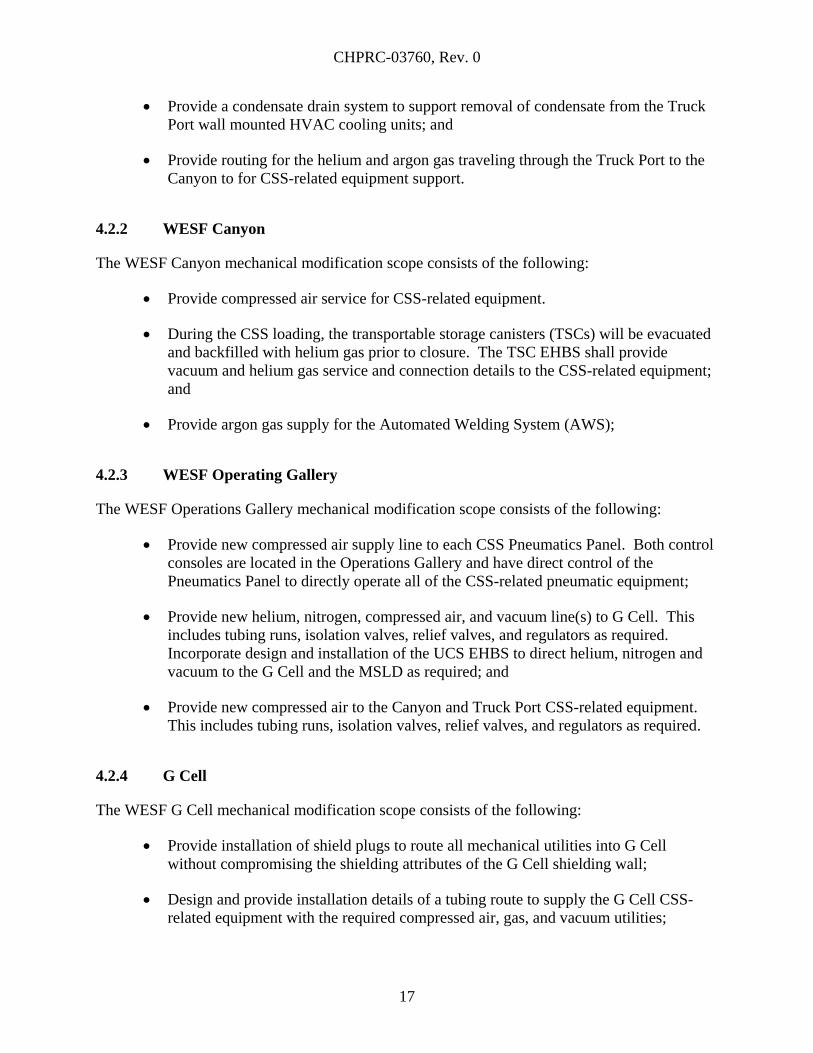
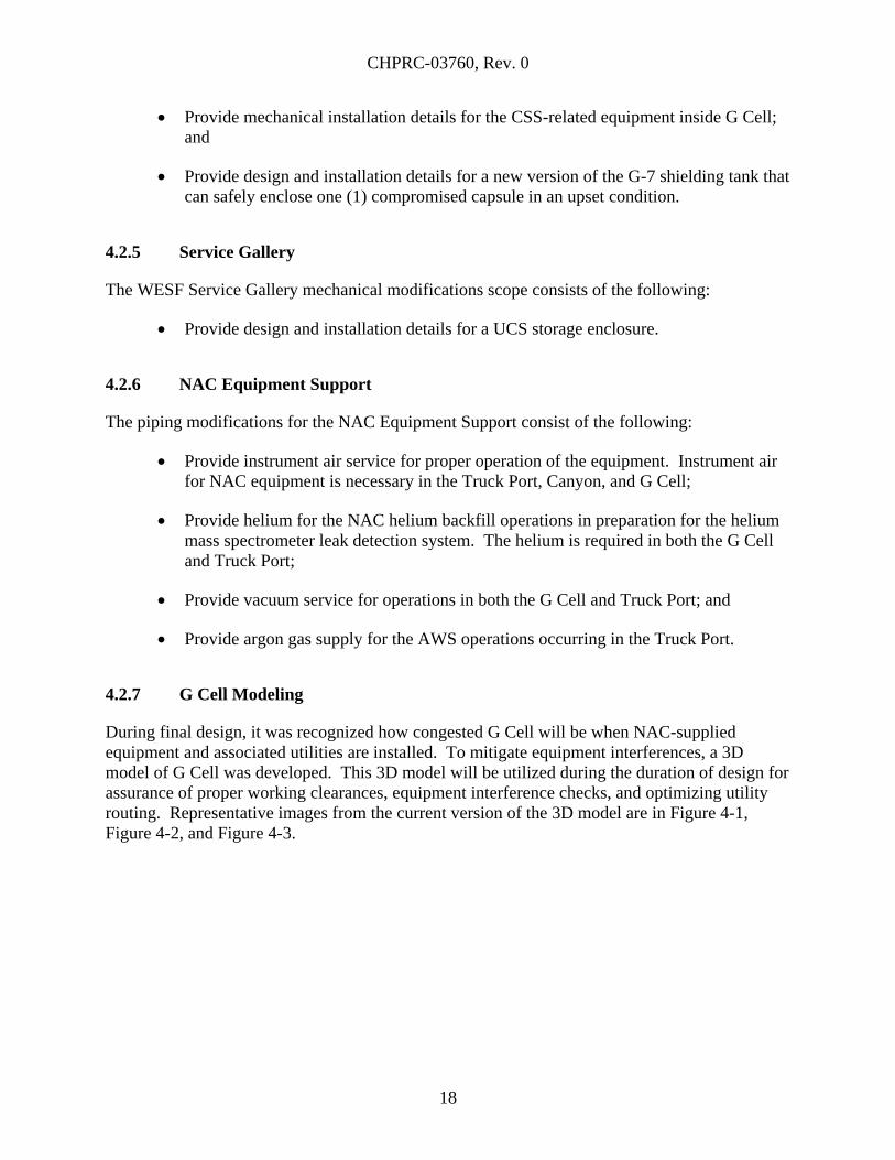
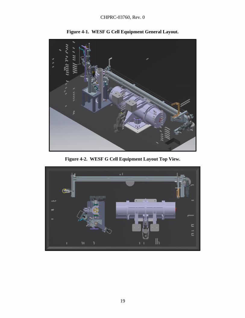
4.2.7 G Cell Modeling
During final design, it was recognized how congested G Cell will be when NAC-supplied
equipment and associated utilities are installed. To mitigate equipment interferences, a 3D
model of G Cell was developed. This 3D model will be utilized during the duration of design for
assurance of proper working clearances, equipment interference checks, and optimizing utility
routing. Representative images from the current version of the 3D model are in Figure 4-1,
Figure 4-2, and Figure 4-3.
CHPRC-03760, Rev. 0
19
Figure 4-1. WESF G Cell Equipment General Layout.
Figure 4-2. WESF G Cell Equipment Layout Top View.
CHPRC-03760, Rev. 0
20
Figure 4-3. WESF G Cell Transfer Chute and RTA Interface.
4.3 MECHANICAL (HVAC) ENGINEERING
The mechanical HVAC design for the WESF Modifications portion of Project W-135 is
addressed in the following section. The HVAC design is required to mitigate the heat load
generated by the capsules during capsule retrieval and loading into the CSS in preparation for
transfer to the CSA.
4.3.1 WESF Configuration
For the purposes of cooling system design, the following WESF facility configurations were
assumed. Details on the heat loads and assumptions supporting them are found in report
CHPRC-03768, W-135 WESF Modifications – HVAC Calculations.
G Cell:
o There is a loaded UCS in G Cell
o The hottest canister is in the G-7A tank in G Cell
CHPRC-03760, Rev. 0
21
Canyon:
o The opening between the truck port and the canyon is uncovered, and there is a
fully loaded VCC in the truck port
o There is a loaded UCS in the DTS
o The canyon crane and CSS equipment are operating at an assumed duty cycle
o All heat from the AWS rises into the canyon
o A portion of the heat from the loaded VCC rises into the canyon
Truck Port:
o The opening between the truck port and the canyon is covered, preventing heat
rise into the canyon
o There is a fully loaded VCC in the truck port
As part of the calculations supporting the design, it was assumed that the existing K1 and K3
systems adequately cooled summer heat loads (including personnel) and lighting in the truck port
and canyon, respectively.
4.3.1.1 G Cell Cooling
Approximately 600 cfm of flow is required to remove the heat load generated by capsules in cell
and maintain ambient temperatures at less than 80°F with the cooling equipment that has been
selected for the design. In order to provide the required cooling the G Cell exhaust will be
isolated from the K3 ventilation system by removing the existing duct transition and adding a
tee, a new isolation damper, and a new shorter transition piece. The damper on the K3 side of
the tee will be closed, and a high-efficiency particulate air (HEPA) filter housing and blower will
be connected to the branch end of the tee. This will allow G Cell ventilation to be both supplied
from and discharged into the canyon, which eliminates the need for the K3 system to supply the
required airflow rate.
The G Cell HEPA filter housing supports DOP (Dioctyl Phthalate) testing, bag-in/bag-out of
filter elements, and a gel seal. The housing is rated at 30 iwg vacuum.
The existing chilled water cooling coil in the G Cell inlet duct will be replaced with a direct
expansion cooling coil. An outdoor condenser unit will be located on the existing vacuum pump
slab on the south side of WESF. Refrigerant lines will be routed outside of the building to a
point opposite from the coiling coil, where the refrigerant lines will enter the canyon. The
penetration will be sealed with expandable foam. The existing pre-filter housing will be
removed and reinstalled on top of the new cooling coil.
CHPRC-03760, Rev. 0
22
The seismic response of the 225-B building was analyzed. The analysis indicated that all
penetrations will be 3 in. or smaller.
An airflow of 600 cfm through the existing 6-in. G Cell supply and exhaust duct, the pre filter,
new cooling coil, new duct, and HEPA filters will result in a pressure in G Cell of -3.3 iwg.
4.3.1.2 G Cell Supply Air Mixing
Vanes will be added to the G Cell supply duct to direct the airflow down and away from the
exhaust duct. This will promote circulation of cooling air through the cell and assist in
mitigating the possibility of the cooling air short circuiting back to the exhaust duct without
cooling the floor mounted capsule handling equipment.
4.3.2 Canyon Airflow and Cooling
During CSS loading operations the truck port will be open to the canyon, which is an area of
potentially higher contamination levels than the truck port. To prevent the spread of
contamination the canyon should be maintained at a lower pressure than the truck port so that
any airflow moves from the truck port to the canyon. To achieve this airflow into the canyon,
the exhaust damper (VD-TP-K1-100) on the new K1 truck port duct should be adjusted to close
off some or all of the airflow exhausting from the truck port. This will allow the air being
supplied by K1 to the truck port to be drawn through the opening and into the K3 exhaust. The
K3 exhaust fans could also be adjusted to draw more air from the canyon, if needed. Testing
should be performed after modification of the K1 truck port duct and the G Cell exhaust system
to determine the optimal amount of adjustment needed to achieve the desired airflow.
Additional cooling will be added to the canyon to address heat loads caused by capsule handling
and transfer in the DTS and heat as a result of welding on the TSC. Cooling will be provided by
the same system that will cool the truck port. See the truck port cooling section for more
discussion of the cooling system.
4.3.3 Truck Port Cooling
The truck port requires additional cooling when the capsules are placed into the CSS. The truck
port temperature should not exceed 80°F.
Cooling is to be performed using commercial outdoor and indoor variable refrigerant flow (VRF)
units. Variable-capacity outdoor units modulate the amount of refrigerant needed based on the
cooling and heating demands of the indoor units allowing for reduced energy usage at partial
load conditions.
The outdoor unit will be located on an existing pad next to the south wall of the service gallery.
The indoor units are wall mounted coil/fan units specifically designed to work with the specified
VRF outdoor unit. The indoor units will be wall mounted eight feet above floor level around the
CSS.
CHPRC-03760, Rev. 0
23
The recommended VRF units are designed, built, and tested to industry HVAC standards and a
nationally recognized quality program. Each unit is tested by the manufacturer to verify proper
operation prior to sale.
The refrigeration piping will be installed to nationally recognized standards. This ensures that
the piping will be fabricated and installed in such a manner as to function reliably. Redundancy
has been designed in to the system by providing more units than typically required. The truck
port and canyon require approximately 13 tons of cooling capacity. Typically this would be
provided by two ten ton outdoor heat pump units, three indoor units in the truck port, and two
indoor units in the canyon. The design for WESF will install three ten ton outdoor heat pump
units, six indoor units in the truck port, and four indoor units in the canyon.
The outdoor units communicate to control the quantity of refrigerant provided to the indoor units
based on the demand. One outdoor unit is the lead unit, which provides direction to the other
units. During normal operations the three units will modulate to provide the required cooling. If
one of the outdoor units fails, the other two units have sufficient capacity to meet the cooling
load. If the unit that fails is the lead unit, the control wiring can be moved to another unit which
can be designated the lead unit using dip switches on the unit controls.
There are redundant indoor units installed in both the truck port and the canyon. If an indoor
unit fails, the remaining indoor units can meet the cooling demand. Indoor units can be easily
replaced by disconnecting the refrigerant lines, removing the unit, and installing a spare unit.
4.3.4 Use of Commercial HVAC Equipment
The units providing cooling in the truck port, canyon, and G Cell are commercial units, and are
not specifically designed for operation in high radiation fields. However, the capsule handling
and storage equipment, such as the DTS and VCC, are designed to provide sufficient shielding to
minimize radiation during operations. The highest radiation levels will likely be directly over
the VCC, and will be a result of radiation streaming from the UCS ports.
The cooling units are located such that they are out of this path of expected highest radiation.
The units in the truck port are located below the top of the VCC, and will be protected by the
VCC shielding. The G Cell cooling coil is located sufficiently far enough from the truck port
opening in the canyon that it will not be exposed to the radiation from the top of the VCC. The
canyon cooling units are located around the truck port opening, and are the closest to the source
of radiation, but should be out of the direct streaming path and thus not exposed to the highest
levels of radiation. In the case of the truck port and canyon, redundant units are installed, and
failure of one or even two units in either location will not affect the ability of the system to
provide the required cooling.
The units are located to reduce exposure to radiation, and redundant units are provided. As such,
the risk of operating commercial units in potential radiation fields is considered to be low.
CHPRC-03760, Rev. 0
24
4.3.5 Truck Port Air Circulation
The current truck port ventilation airflow pattern is not very efficient at accessing the entire truck
port. The ventilation supply location is adjacent to the exhaust location, effectively short
circuiting the airflow as the air that moves from the supply duct is almost immediately captured
by the exhaust duct.
The solution is to close the damper on the existing exhaust vent and install a new exhaust vent
into the existing K1 exhaust ducting in the northwest corner of the truck port. The K1 system
will be rebalanced to accept the system changes.
4.3.6 WESF Truck Port K1 Duct Reroute
A reroute of the K1 duct in the truck port is required to eliminate an interference with the CSS.
4.3.6.1 Existing K1 Truck Port Duct
The existing WESF K1 exhaust duct currently runs from the ceiling to the floor in the truck port.
The movement of the CSS into the truck port during capsule handling operations will interfere
with the existing K1 duct.
4.3.6.2 Demolition of the Existing K1 Truck Port Duct
A significant portion of the existing K1 duct will be removed. The existing duct will be cut
approximately 4 in. from the ceiling as well as approximately 2 in. above the damper interface.
This will provide existing connect locations for the new ducting. The existing steam system
piping on the north wall above the damper will also be removed. This piping and electrical is
inactive and will not affect existing systems upon removal.
4.3.6.3 Installation of New K1 Truck Port Duct
The new proposed K1 duct will be installed from the existing ceiling penetration to the damper.
The new K1 duct will route along the ceiling in the previous 14 in. by 14 in. square configuration
to a location approximately over the centerline of the damper.
The new K1 duct will then transition to a flattened duct that will route down the truck port north
wall. The flattened duct is sized to provide almost the same airflow hydraulic duct size as the
14 x 14 in. duct while at the same time maintaining adequate clearance close to the wall to
prevent interference with the cask. The flattened duct will extend approximately 10 in. from the
wall.
4.4 ELECTRICAL ENGINEERING
The electrical design for the WESF Modifications portion of Project W-135 addresses design of
all electrical work required to support capsule retrieval and loading into the CSS in preparation
for transfer to the CSA. These design topics are described and detailed in the following
subsections.
CHPRC-03760, Rev. 0
25
4.4.1 WESF Truck Port
The WESF Truck Port electrical modifications consist of the following activities:
Provide power and controls to new rollup door operator.
o Remove existing disconnect switch from inside of the Truck Port, and install a
new switch outside adjacent to the new door. The existing disconnect switch
must be removed to provide clearance for CSS transport and to make space for the
K1 duct replacement, and the disconnecting means is required to be within sight
of the door operator motor which will be located on the outside of the door due to
space constraints.
o Provide lockable pushbutton stations on the interior and exterior walls to operate
the new door from either side.
o Connect new door limit switches to existing instrumentation and control (I&C)
wiring to the S Panels.
o Connect new door operator to existing power wiring from MCC-1.
Provide power and controls to HVAC equipment installed to cool the Truck Port
including multiple indoor and outdoor units, and local thermostat. Provide conduit
and control/communications wiring between HVAC components.
o Provide power to HVAC equipment through an abandoned conduit that is routed
from the Mechanical Room, over the WESF roof, and down the south side of the
exterior wall. Conduit will be intercepted and extended to the HVAC outdoor
units, and new feeder installed from MCC-2. The feeder circuit breaker in
MCC-2 will be replaced.
o Provide power to HVAC condensate pump.
Remove existing unit heater located near the truck port door to provide clearance for
CSS transport, and spare out the 120V control circuit.
Remove existing wall-mounted camera, and install two cameras on north and south
walls. Cameras will be rad hardened and will have color, auto-focus, pan-tilt-zoom
capabilities. Cameras will be controlled from and monitored at the Process Crane
Operator Station and the Operating Gallery Control Area. Existing camera conduit
into the Truck Port will be utilized, and additional conduit will be installed to the
second camera location.
Install temperature probes to remotely record temperatures near the CSS air inlets,
and to alarm on high temperature. Alarm will be transmitted to an annunciator (by
CSS/NAC) in control panel PNL-TP-1. The ATMS is safety significant. All
components will be procured as safety significant quality level 2. Conduit for ATMS
wiring will be rigid galvanized steel.
CHPRC-03760, Rev. 0
26
4.4.2 WESF Canyon
The WESF Canyon electrical modifications consist of the following:
Provide power to the portable AWS power source from the existing Canyon weld
receptacle via a portable power cart with 480V weld receptacles and 120V
receptacles. Provide I&C wiring from the portable AWS remote viewing console in
the Operating Gallery to the AWS power source in the Canyon.
Provide power and I&C cabling to the Dry Transfer System, Shield Indexer
Assembly, and G Cell Cover Block Gate in accordance with CSS/NAC equipment
cabling requirements. Cables originate at Canyon/Truck Port Control Panel
PNL-TP-1 located in the Operating Gallery and terminate in the Canyon. Cable reels
will be installed for DTS power and I&C, so cables can stay connected when the DTS
is moved from the G Cell Cover Block Gate to the Shield Indexer Assembly.
Provide power and controls to HVAC equipment installed to cool the Canyon
including multiple indoor and outdoor units, and a local thermostat. Provide conduit
and control/communications wiring between HVAC components.
Provide power and controls to HVAC equipment to cool G Cell, located in the
Canyon, including G Cell exhaust fan and local thermostat. The exhaust fan is
controlled by a variable frequency drive.
Provide power to the TSC EHBS vacuum pump.
Conductors originating in the Operating Gallery and terminating at equipment in the
Canyon will be routed via conduit through the Operating Gallery ceiling, into the
Manipulator Repair Shop, and through wall penetrations into the Canyon.
Install replacement camera system to support safe and precise movement of crane
loads.
o Existing cameras mounted on the Canyon walls and the Canyon crane bridge and
trolley will be replaced. Cameras will provide overhead views of the crane hoist
as well as overhead views of work area with a minimum of two crossing
directions. The Canyon length and Truck Port area above the CSS will be
viewable so that direct downward views of the work areas can be achieved.
o The existing cable carrier tracks, mounted on the canyon wall for bridge
movement, and mounted on the crane bridge for trolley movement, will be used to
pay out cables to the bridge and trolley cameras. Existing camera cables will be
removed from the cable tracks and replaced with heavy-duty camera cables
suitable for use in the environment.
o Cameras will be rad hardened and will have color, auto-focus, pan-tilt-zoom
capabilities.
CHPRC-03760, Rev. 0
27
o Cameras will be able to be controlled or monitored at the new camera control
workstation at the Process Crane Operator Station (PCOS), or at either control
panel PNL-G-4 or PNL-TP-1 in the Operating Gallery. Camera controls and two
monitors and will be provided at each of these three locations.
Install temperature probes to remotely record temperatures near the work platform,
and to alarm on high temperature. Alarm will be transmitted to an annunciator (by
CSS/NAC) in control panel PNL-TP-1. The ATMS is safety significant. All
components will be procured as safety significant quality level 2. Conduit for ATMS
wiring will be rigid galvanized steel.
4.4.3 WESF G Cell
The WESF G Cell electrical modifications consist of the following:
Provide power and I&C cabling to the Upender Assembly, Test Cover Assembly, Nut
Runners, Recovery Transfer Assembly, and Recovery Shield Assembly. Cables
originate at the G Cell Port Control Panel PNL-G-4 located in the Operating Gallery.
Conductors originating in the Operating Gallery and terminating at equipment in
G Cell will be routed through existing 1 in. electrical penetrations into G Cell and
terminated at G Cell equipment. Connection inside G Cell will be through shielded
terminal boxes mounted on penetration nozzles, then plug and cord connected from
boxes to equipment. Cables and connectors are rad hardened, and cables are routed to
minimize dose. Shielded boxes, connectors, and cables will be specified by
CSS/NAC and installed by the WESF Mods construction contractor.
Install two cameras inside G Cell as high on wall as possible but below the G Cell
crane trolley. Cameras will be rad hardened and will have color, auto-focus, pan-tilt-
zoom capabilities. Cameras will be able to be controlled or monitored at PCOS
camera control workstation, or at either control panel PNL-G-4 or PNL-TP-1 in the
Operating Gallery. Existing 1” penetrations into G Cell will be used to route the rad
hardened camera cables.
Install temperature probes to remotely record temperatures inside G Cell in locations
specified by CSS/NAC, and to alarm on high temperature. Alarm will be transmitted
to an annunciator (by CSS/NAC) in control panel PNL-G-1. The ATMS is safety
significant. All components will be procured as safety significant quality level 2.
Conduit for ATMS wiring will be rigid galvanized steel.
4.4.4 WESF Operating Gallery
The WESF Operating Gallery electrical modifications consist of the following:
A new Control Area will be established for process operations. Equipment includes
Canyon/Truck Port Equipment Control Panel PNL-TP-1 (by CSS/NAC), G Cell
CHPRC-03760, Rev. 0
28
Equipment Control Panel PNL-G-4 (by CSS/NAC), AWS remote viewing console
(Government Furnished Equipment), Power Control Panel PNL-G/TP-1 (by
CSS/NAC), Pneumatics Control Panel PNL-G/TP-2 (by CSS/NAC), and ATMS
Control Panel PNL-G/TP-3.
Provide power to control panels listed above, and to miscellaneous loads including
UCS EHBS vacuum pump, camera controls, and portable MSLD cart.
Provide power and I&C cabling to equipment listed above and to utilization
equipment in the Canyon and G Cell.
Provide I&C cabling for AWS remote viewing console to AWS power source in
Canyon. Remote viewing console is portable, and cabling will be cord and plug
connected from a terminal box.
Provide support racks and anchors for control panels and other electrical equipment in
Operating Gallery. Support racks and anchors are safety significant and will be
procured as safety significant quality level 2.
Provide power to air compressor CMP-G-1.
Provide controls and video monitors for camera system at control panels PNL-G-4
and PNL-TP-1. Mounts for two monitors at each control panel and space for controls
(keyboard and joystick) will be provided by CSS/NAC.
Install ATMS Control Panel PNL-G/TP-3 near the Control Area. PNL-G/TP-3
accepts temperature signals from RTDs in the Truck Port, Canyon and G Cell.
Temperatures are recorded on a 10 channel data recorder. If a high temperature is
detected, an alarm signal is sent to the appropriate annunciator on PNL-G-4 or
PNL-TP-1. The ATMS is safety significant and will be procured as safety significant
quality level 2. Conduit for ATMS wiring will be rigid galvanized steel.
4.5 FIRE PROTECTION
The fire protection design for the WESF Modifications portion of Project W-135 addresses
design of all fire protection work required to support capsule retrieval and loading into the CSS
in preparation for transfer to the CSA. These design topics are described and detailed in the
following subsections.
CHPRC-03760, Rev. 0
29
4.5.1 WESF Truck Port
WESF Truck Port fire protection modifications consist of the following:
Design of Truck Port sprinkler system modification to elevate the sprinklers over the
port for clearance; and
Design of removal of abandoned small diameter sprinkler in the Truck Port.
4.6 FUNCTIONAL ELEMENTS
CHPRC-03011 provides the design requirements and technical baseline for the WESF
Modifications portion of Project W-135. The following sections describe the Project W-135
functional elements and their applicable requirements.
4.6.1 Fire Protection
The existing WESF Truck Bay, wet pipe automatic sprinkler system, has been shown to be
incapable of suppling the flows and pressures, required for the recommended protection of the
area, and the existing piping arrangement will interfere with the movement of the storage cask.
To correct these issues the existing piping shall modified to reduce the pressure requirements and
arranged in a manner that will not interfere with the cask operations following the requirements
of National Fire Protection Association (NFPA) 13, Standard for the Installation of Sprinkler
Systems.
4.6.2 Worker Health and Safety
Project W-135 follows PRC-MP-SH-32219, Worker Safety and Health Program Description,
which complies with Title 10, Code of Federal Regulations, Part 851, “Worker Safety and
Health Program” (10 CFR 851), which invokes applicable parts of the following:
Title 29, Code of Federal Regulations, Part 1926, “Safety and Health Regulations for
Construction” (29 CFR 1926); and
Title 29, Code of Federal Regulations, Part 1910, “Occupational Safety and Health
Standards” (20 CFR 1910).
Project W-135 will use the CHPRC Integrated Safety Management System described in
PRC-MP-MS-003, Integrated Safety Management System/Environmental Management System
Description, to identify specific hazards associated with any given task. Additionally, Project
W-135 will:
Perform work in a safe, compliant manner that adequately protects the employees, the
public and the environment.
CHPRC-03760, Rev. 0
30
Ensure that S&L, and their lower-tier subcontractors, comply with applicable laws
and requirements.
Perform work in accordance with a CHPRC approved safety and health procedure.
Implement the preapproved procedures included in PRC-PRC-SH-40078, Contractor
Safety Processes, Appendix F, “Safety Program Specifications For Contractors,” or
submit an alternative program for approval. This alternative safety and health
program shall comply with federal, state, and local codes and PRC-PRC-SH-40078,
Appendix F.
During final design, all items that can be removed or relocated without undue impact on other
site operations have been identified and plans developed to facilitate that removal/relocation
effort.
4.6.3 Radiological Control
As low as reasonably achievable (ALARA) is the project’s approach to radiation protection
management. Controlling exposures (both individual and collective) to the work force and to the
general public is paramount to successful implementation of any project. Fundamentally,
ALARA is not a dose limit; it is a process that has the objective of attaining doses as far below
the applicable limits as is reasonably achievable.
The design ensures that radiation exposure to workers and the public, and releases of
radioactivity to the environment, are maintained below regulatory limits. The design also
considered contamination control, shielding, remote activities, failure recovery, and
maintenance.
As a general approach, the ALARA principles were incorporated into the design and will include
the requirements of Title 10, Code of Federal Regulations, Part 835, “Occupational Radiation
Protection” (10 CFR 835) Subpart K, “Design and Control.” The basic requirements concerning
the use of ALARA aspects related to this design are imposed in DOE-STD-1098-99,
Radiological Control, CHPRC-00072, CHPRC Radiation Protection Program, CHPRC-00073,
CHPRC Radiological Control Manual, and PRC-PRO-RP-1622, Radiological Design Review
Process. Specific requirements for ALARA Analysis are contained in PRC-PRO-RP-1622.
Physical design features (distance) was the primary method used to maintain exposures ALARA.
Optimization methods were used to ensure that occupational exposure is maintained ALARA in
developing and justifying the facility design and controls.
4.6.4 Environmental
The WESF Modifications portion of Project W-135 will conform to applicable Federal and State
regulations. Project demolition and decommissioning will be accomplished in accordance with
CHPRC-03760, Rev. 0
31
Hanford Site and CHPRC waste management, waste minimization, and demolition and
decommissioning requirements.
Project W-135 will comply with the information within the Resource Conservation and Recovery
Act Part B permit applications and applicable requirements of the following sections of WAC
173-303:
WAC 173-303-280 – General Requirements For Dangerous Waste Management Facilities
WAC 173-303-281 – Notice of Intent
WAC 173-303-282 – Siting Criteria
WAC 173-303-283 – Performance Standards
WAC 173-303-290 – Required Notices
WAC 173-303-300 – General Waste Analysis
WAC 173-303-310 – Security
WAC 173-303-320 – General Inspection
WAC 173-303-330 – Personnel Training
WAC 173-303-335 – Construction Quality Assurance Program
WAC 173-303-340 – Preparedness and Prevention
WAC 173-303-350 – Contingency Plan and Emergency Procedures
WAC 173-303-360 – Emergencies
WAC 173-303-370 – Manifest System
WAC 173-303-380 – Facility Recordkeeping
WAC 173-303-390 – Facility Reporting
WAC 173-303-395 – Other General Requirements
WAC 173-303-600 – Final Facility Standards
WAC 173-303-610 – Closure and Post-Closure
WAC 173-303-630 – Use and Management of Containers
WAC 173-303-680 – Miscellaneous Units
WAC 173-303-803 – Permit Application Requirements
WAC 173-303-806 – Final Facility Permits
WAC 173-303-830 – Permit Changes
4.6.5 Safeguards and Security
Project W-135 shall comply with applicable requirements contained in DOE O 470.4B,
Safeguards and Security Program. The need for security to prevent unauthorized access to
nuclear materials has been assessed to prevent theft, vandalism, and other malicious acts that
could release radioactive material or disrupt facility operations.
The new roll-up door for the truck port is being provided with manual locking capability as well
as a key-controlled electric door operator.
CHPRC-03760, Rev. 0
32
4.6.6 Criticality
There are no fissile materials associated with the cesium and strontium capsules; therefore,
criticality is not a concern and criticality control measures are not a requirement of
Project W-135.
4.6.7 Quality Assurance
Project activities have been performed in accordance with the S&L-approved QA Program and
implementing procedures. This program meets the requirements of American Society of
Mechanical Engineers (ASME) NQA-1-2008, Quality Assurance Requirements for Nuclear
Facility Applications, with the ASME NQA-1a-2009 addenda. ASME NQA-1 is the
implemented standard endorsed by DOE O 414.1D, Quality Assurance; and 10 CFR 830,
Subpart A, “Quality Assurance Requirements.” Application of QA requirements of
10 CFR 830.122, “Quality Assurance Criteria,” were applied to items and activities using a
graded approach as defined in PRC-PRO-QA-259, Graded Approach, and PRC-PRO-NS-700.
Quality requirements of CHPRC-00189, CH2M HILL Plateau Remediation Company
Environmental Quality Assurance Program Plan, were applied.
4.6.8 Test Plans
A Test Plan (CHPRC-03452, W-135 WESF Modifications Test Plan) has been developed to
serve as an overarching document that identifies the method, extent, component/system
interfaces, and sequence of the planned testing for Project W-135. This Test Plan has been
developed by CHPRC and encompasses the entire scope of Project W-135 – the CSA, the CSS,
and the WESF Modifications.
Specifically, the testing documentation that the WESF Modification design effort produced in
the final design phase are as follows:
Construction Test Plan; and
Design/Construction Verification Plan.
4.6.9 Safety Equipment List
A Safety Equipment List (SEL) for the WESF Modifications (CHPRC-03831) has been created
for the facility modifications that will be performed. This Preliminary Safety Equipment List
(provided as a draft during Final Design) identifies the safety-significant SSCs that will be
installed or modified. The SSCs perform safety functions specified per NAC document
30059-Q-01, Quality Category Assessment for the Hanford MCSC Project Cask Storage System,
CHPRC-03744, Preliminary Documented Safety Analysis for the Capsule Storage Area (PDSA),
and project meeting decisions. Upon completion of WESF Modifications, the WESF
Documented Safety Analysis (HNF-8758) and HNF-SD-WM-SEL-008, Waste Encapsulation
and Storage Facility Safety Equipment List ((hereinafter referred to as the “SEL”), will be
CHPRC-03760, Rev. 0
33
revised to include the components listed in this Draft SEL with credited safety functions. Final
design is based on this version of the SEL.
4.6.10 Decontamination and Decommissioning
Project W-135 shall comply with the design criteria in DOE O 430.1C and 10 CFR 835. Designs
consistent with the program requirements of DOE O 430.1C were developed during the planning
and design phases based on a proposed decommissioning method, or a conversion method
leading to other uses. SSCs include features that will facilitate decontamination for future
decommissioning, increase the potential for other uses, or both. Design or modification of the
facility and selection of materials also includes features that facilitate decontamination and
decommissioning.
Features of the design considered for future decontamination and decommissioning are listed
below.
Stainless steel materials were used in G Cell and the Truck Port (which is easy to
decontaminate).
There are two vacuum lines that interact with G Cell (TCA-VHN-1A and
TCA-VHN-1B). They both originate from the UCS EHBS rack, see
H-2-837762. The HEPA filters incorporated within the assembly are TCA-F-1,
TCA-F-2, TCA-F-3, and TCA-F-4. The HEPA filters are designed to be unfastened
and radiologically surveyed when desired. This allows Operations to validate the
cleanliness of the downstream equipment for easy maintenance, disposal, and/or
replacement. The downstream equipment that the HEPA filters protect include:
MSLD, EHBS-P-1 vacuum pump, calibrated Helium leak source, and general gauges
and valves.
Project W-135 will also incorporate the following design principles:
Provide equipment that precludes, to the extent practical, accumulation of radioactive
or other hazardous materials in relatively inaccessible areas.
Use materials that reduce the amount of radioactive and other hazardous materials
requiring disposal, and materials easily decontaminated.
Incorporate designs that facilitate cut-up, dismantlement, removal, and packaging of
contaminated equipment and components at the end of useful life.
Use modular radiation shielding, in lieu of or in addition to monolithic shielding
walls.
Equipment that is likely to become contaminated shall have special coatings that
facilitate decontamination. The design should consider use of rounded corners and
epoxy-coated walls in areas that handle or store radioactive material. Finishes shall
meet the requirements set forth in ANSI N512, Protective Coatings (Paints) for the
CHPRC-03760, Rev. 0
34
Nuclear Industry. However, Project W-135 will not upgrade existing surfaces at
WESF solely to facilitate decontamination.
4.6.11 Design Life
Components have been designed such that the continued integrity of the component can be
verified over the design life to ensure continued functionality within original requirements. All
systems and equipment have been designed, to the maximum extent practical, to provide a
minimum five-year, maintenance-free service life.
Consumables have a one-year minimum service life and are located for ease of inspection,
maintenance, and replacement.
The Truck Port and Transfer Station modifications and associated equipment have been designed
with a minimum design life of ten years.
4.6.12 Reliability, Availability, and Maintainability
The design has considered requirements associated with reliability, maintainability, and
inspectability. The design has provided for routine maintenance, repair, or replacement of
equipment subject to failure. Remote maintenance is not needed for any equipment.
5.0 FINAL DESIGN DOCUMENT INVENTORY
Refer to Appendix A for the Equipment List, Appendix B for the Human Factors Engineering
Report, Appendix C for the Design Input Matrix, Appendix D for the AG-1 Compliance Matrix,
Appendix E for the FDC Compliance Matrix, and Appendix F for the NAC Government
Furnished Equipment List.
The following tables identify other design media that was developed for the project. Table 5-1
identifies the drawings, and the Facility Modification Packages (FMPs) are shown in Table 5-2.
The construction specification is identified in Table 5-3. Table 5-4 provides the listing of
calculations, and other supporting engineering design documents are shown in Table 5-5 (some
are appendices to this FDR and some are stand-alone documents). The design media identified
in the tables (except those appended to this FDR) are final documents and will be released at the
completion of the final design.
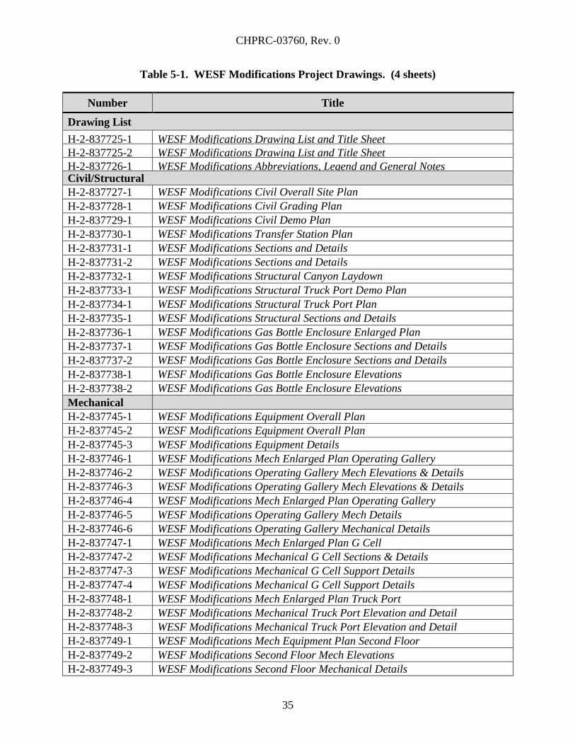
CHPRC-03760, Rev. 0
35
Table 5-1. WESF Modifications Project Drawings. (4 sheets)
Number Title
Drawing List
H-2-837725-1 WESF Modifications Drawing List and Title Sheet
H-2-837725-2 WESF Modifications Drawing List and Title Sheet
H-2-837726-1 WESF Modifications Abbreviations, Legend and General Notes Civil/Structural
H-2-837727-1 WESF Modifications Civil Overall Site Plan
H-2-837728-1 WESF Modifications Civil Grading Plan
H-2-837729-1 WESF Modifications Civil Demo Plan
H-2-837730-1 WESF Modifications Transfer Station Plan
H-2-837731-1 WESF Modifications Sections and Details
H-2-837731-2 WESF Modifications Sections and Details
H-2-837732-1 WESF Modifications Structural Canyon Laydown
H-2-837733-1 WESF Modifications Structural Truck Port Demo Plan
H-2-837734-1 WESF Modifications Structural Truck Port Plan
H-2-837735-1 WESF Modifications Structural Sections and Details
H-2-837736-1 WESF Modifications Gas Bottle Enclosure Enlarged Plan
H-2-837737-1 WESF Modifications Gas Bottle Enclosure Sections and Details
H-2-837737-2 WESF Modifications Gas Bottle Enclosure Sections and Details
H-2-837738-1 WESF Modifications Gas Bottle Enclosure Elevations
H-2-837738-2 WESF Modifications Gas Bottle Enclosure Elevations
Mechanical
H-2-837745-1 WESF Modifications Equipment Overall Plan
H-2-837745-2 WESF Modifications Equipment Overall Plan
H-2-837745-3 WESF Modifications Equipment Details
H-2-837746-1 WESF Modifications Mech Enlarged Plan Operating Gallery
H-2-837746-2 WESF Modifications Operating Gallery Mech Elevations & Details
H-2-837746-3 WESF Modifications Operating Gallery Mech Elevations & Details
H-2-837746-4 WESF Modifications Mech Enlarged Plan Operating Gallery
H-2-837746-5 WESF Modifications Operating Gallery Mech Details
H-2-837746-6 WESF Modifications Operating Gallery Mechanical Details
H-2-837747-1 WESF Modifications Mech Enlarged Plan G Cell
H-2-837747-2 WESF Modifications Mechanical G Cell Sections & Details
H-2-837747-3 WESF Modifications Mechanical G Cell Support Details
H-2-837747-4 WESF Modifications Mechanical G Cell Support Details
H-2-837748-1 WESF Modifications Mech Enlarged Plan Truck Port
H-2-837748-2 WESF Modifications Mechanical Truck Port Elevation and Detail
H-2-837748-3 WESF Modifications Mechanical Truck Port Elevation and Detail
H-2-837749-1 WESF Modifications Mech Equipment Plan Second Floor
H-2-837749-2 WESF Modifications Second Floor Mech Elevations
H-2-837749-3 WESF Modifications Second Floor Mechanical Details
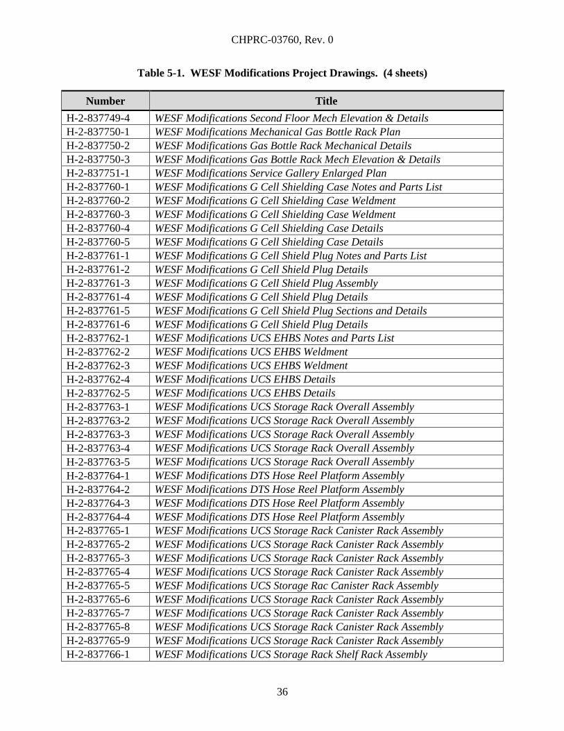
CHPRC-03760, Rev. 0
36
Table 5-1. WESF Modifications Project Drawings. (4 sheets)
Number Title
H-2-837749-4 WESF Modifications Second Floor Mech Elevation & Details
H-2-837750-1 WESF Modifications Mechanical Gas Bottle Rack Plan
H-2-837750-2 WESF Modifications Gas Bottle Rack Mechanical Details
H-2-837750-3 WESF Modifications Gas Bottle Rack Mech Elevation & Details
H-2-837751-1 WESF Modifications Service Gallery Enlarged Plan
H-2-837760-1 WESF Modifications G Cell Shielding Case Notes and Parts List
H-2-837760-2 WESF Modifications G Cell Shielding Case Weldment
H-2-837760-3 WESF Modifications G Cell Shielding Case Weldment
H-2-837760-4 WESF Modifications G Cell Shielding Case Details
H-2-837760-5 WESF Modifications G Cell Shielding Case Details
H-2-837761-1 WESF Modifications G Cell Shield Plug Notes and Parts List
H-2-837761-2 WESF Modifications G Cell Shield Plug Details
H-2-837761-3 WESF Modifications G Cell Shield Plug Assembly
H-2-837761-4 WESF Modifications G Cell Shield Plug Details
H-2-837761-5 WESF Modifications G Cell Shield Plug Sections and Details
H-2-837761-6 WESF Modifications G Cell Shield Plug Details
H-2-837762-1 WESF Modifications UCS EHBS Notes and Parts List
H-2-837762-2 WESF Modifications UCS EHBS Weldment
H-2-837762-3 WESF Modifications UCS EHBS Weldment
H-2-837762-4 WESF Modifications UCS EHBS Details
H-2-837762-5 WESF Modifications UCS EHBS Details
H-2-837763-1 WESF Modifications UCS Storage Rack Overall Assembly
H-2-837763-2 WESF Modifications UCS Storage Rack Overall Assembly
H-2-837763-3 WESF Modifications UCS Storage Rack Overall Assembly
H-2-837763-4 WESF Modifications UCS Storage Rack Overall Assembly
H-2-837763-5 WESF Modifications UCS Storage Rack Overall Assembly
H-2-837764-1 WESF Modifications DTS Hose Reel Platform Assembly
H-2-837764-2 WESF Modifications DTS Hose Reel Platform Assembly
H-2-837764-3 WESF Modifications DTS Hose Reel Platform Assembly
H-2-837764-4 WESF Modifications DTS Hose Reel Platform Assembly
H-2-837765-1 WESF Modifications UCS Storage Rack Canister Rack Assembly
H-2-837765-2 WESF Modifications UCS Storage Rack Canister Rack Assembly
H-2-837765-3 WESF Modifications UCS Storage Rack Canister Rack Assembly
H-2-837765-4 WESF Modifications UCS Storage Rack Canister Rack Assembly
H-2-837765-5 WESF Modifications UCS Storage Rac Canister Rack Assembly
H-2-837765-6 WESF Modifications UCS Storage Rack Canister Rack Assembly
H-2-837765-7 WESF Modifications UCS Storage Rack Canister Rack Assembly
H-2-837765-8 WESF Modifications UCS Storage Rack Canister Rack Assembly
H-2-837765-9 WESF Modifications UCS Storage Rack Canister Rack Assembly
H-2-837766-1 WESF Modifications UCS Storage Rack Shelf Rack Assembly
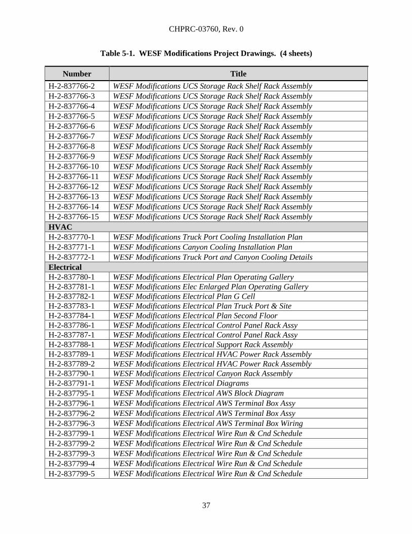
CHPRC-03760, Rev. 0
37
Table 5-1. WESF Modifications Project Drawings. (4 sheets)
Number Title
H-2-837766-2 WESF Modifications UCS Storage Rack Shelf Rack Assembly
H-2-837766-3 WESF Modifications UCS Storage Rack Shelf Rack Assembly
H-2-837766-4 WESF Modifications UCS Storage Rack Shelf Rack Assembly
H-2-837766-5 WESF Modifications UCS Storage Rack Shelf Rack Assembly
H-2-837766-6 WESF Modifications UCS Storage Rack Shelf Rack Assembly
H-2-837766-7 WESF Modifications UCS Storage Rack Shelf Rack Assembly
H-2-837766-8 WESF Modifications UCS Storage Rack Shelf Rack Assembly
H-2-837766-9 WESF Modifications UCS Storage Rack Shelf Rack Assembly
H-2-837766-10 WESF Modifications UCS Storage Rack Shelf Rack Assembly
H-2-837766-11 WESF Modifications UCS Storage Rack Shelf Rack Assembly
H-2-837766-12 WESF Modifications UCS Storage Rack Shelf Rack Assembly
H-2-837766-13 WESF Modifications UCS Storage Rack Shelf Rack Assembly
H-2-837766-14 WESF Modifications UCS Storage Rack Shelf Rack Assembly
H-2-837766-15 WESF Modifications UCS Storage Rack Shelf Rack Assembly
HVAC
H-2-837770-1 WESF Modifications Truck Port Cooling Installation Plan
H-2-837771-1 WESF Modifications Canyon Cooling Installation Plan
H-2-837772-1 WESF Modifications Truck Port and Canyon Cooling Details
Electrical
H-2-837780-1 WESF Modifications Electrical Plan Operating Gallery
H-2-837781-1 WESF Modifications Elec Enlarged Plan Operating Gallery
H-2-837782-1 WESF Modifications Electrical Plan G Cell
H-2-837783-1 WESF Modifications Electrical Plan Truck Port & Site
H-2-837784-1 WESF Modifications Electrical Plan Second Floor
H-2-837786-1 WESF Modifications Electrical Control Panel Rack Assy
H-2-837787-1 WESF Modifications Electrical Control Panel Rack Assy
H-2-837788-1 WESF Modifications Electrical Support Rack Assembly
H-2-837789-1 WESF Modifications Electrical HVAC Power Rack Assembly
H-2-837789-2 WESF Modifications Electrical HVAC Power Rack Assembly
H-2-837790-1 WESF Modifications Electrical Canyon Rack Assembly
H-2-837791-1 WESF Modifications Electrical Diagrams
H-2-837795-1 WESF Modifications Electrical AWS Block Diagram
H-2-837796-1 WESF Modifications Electrical AWS Terminal Box Assy
H-2-837796-2 WESF Modifications Electrical AWS Terminal Box Assy
H-2-837796-3 WESF Modifications Electrical AWS Terminal Box Wiring
H-2-837799-1 WESF Modifications Electrical Wire Run & Cnd Schedule
H-2-837799-2 WESF Modifications Electrical Wire Run & Cnd Schedule
H-2-837799-3 WESF Modifications Electrical Wire Run & Cnd Schedule
H-2-837799-4 WESF Modifications Electrical Wire Run & Cnd Schedule
H-2-837799-5 WESF Modifications Electrical Wire Run & Cnd Schedule
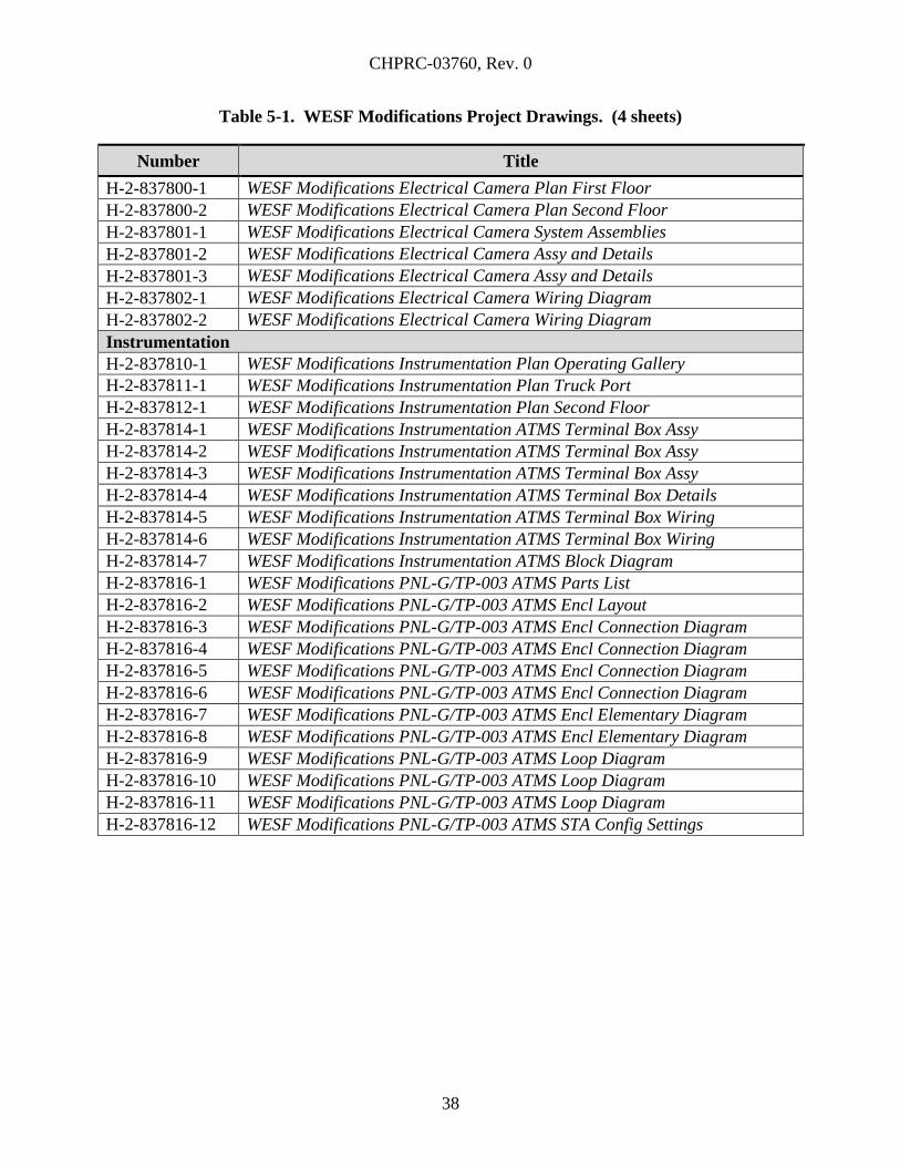
CHPRC-03760, Rev. 0
38
Table 5-1. WESF Modifications Project Drawings. (4 sheets)
Number Title
H-2-837800-1 WESF Modifications Electrical Camera Plan First Floor
H-2-837800-2 WESF Modifications Electrical Camera Plan Second Floor
H-2-837801-1 WESF Modifications Electrical Camera System Assemblies
H-2-837801-2 WESF Modifications Electrical Camera Assy and Details
H-2-837801-3 WESF Modifications Electrical Camera Assy and Details
H-2-837802-1 WESF Modifications Electrical Camera Wiring Diagram
H-2-837802-2 WESF Modifications Electrical Camera Wiring Diagram
Instrumentation
H-2-837810-1 WESF Modifications Instrumentation Plan Operating Gallery
H-2-837811-1 WESF Modifications Instrumentation Plan Truck Port
H-2-837812-1 WESF Modifications Instrumentation Plan Second Floor
H-2-837814-1 WESF Modifications Instrumentation ATMS Terminal Box Assy
H-2-837814-2 WESF Modifications Instrumentation ATMS Terminal Box Assy
H-2-837814-3 WESF Modifications Instrumentation ATMS Terminal Box Assy
H-2-837814-4 WESF Modifications Instrumentation ATMS Terminal Box Details
H-2-837814-5 WESF Modifications Instrumentation ATMS Terminal Box Wiring
H-2-837814-6 WESF Modifications Instrumentation ATMS Terminal Box Wiring
H-2-837814-7 WESF Modifications Instrumentation ATMS Block Diagram
H-2-837816-1 WESF Modifications PNL-G/TP-003 ATMS Parts List
H-2-837816-2 WESF Modifications PNL-G/TP-003 ATMS Encl Layout
H-2-837816-3 WESF Modifications PNL-G/TP-003 ATMS Encl Connection Diagram
H-2-837816-4 WESF Modifications PNL-G/TP-003 ATMS Encl Connection Diagram
H-2-837816-5 WESF Modifications PNL-G/TP-003 ATMS Encl Connection Diagram
H-2-837816-6 WESF Modifications PNL-G/TP-003 ATMS Encl Connection Diagram
H-2-837816-7 WESF Modifications PNL-G/TP-003 ATMS Encl Elementary Diagram
H-2-837816-8 WESF Modifications PNL-G/TP-003 ATMS Encl Elementary Diagram
H-2-837816-9 WESF Modifications PNL-G/TP-003 ATMS Loop Diagram
H-2-837816-10 WESF Modifications PNL-G/TP-003 ATMS Loop Diagram
H-2-837816-11 WESF Modifications PNL-G/TP-003 ATMS Loop Diagram
H-2-837816-12 WESF Modifications PNL-G/TP-003 ATMS STA Config Settings
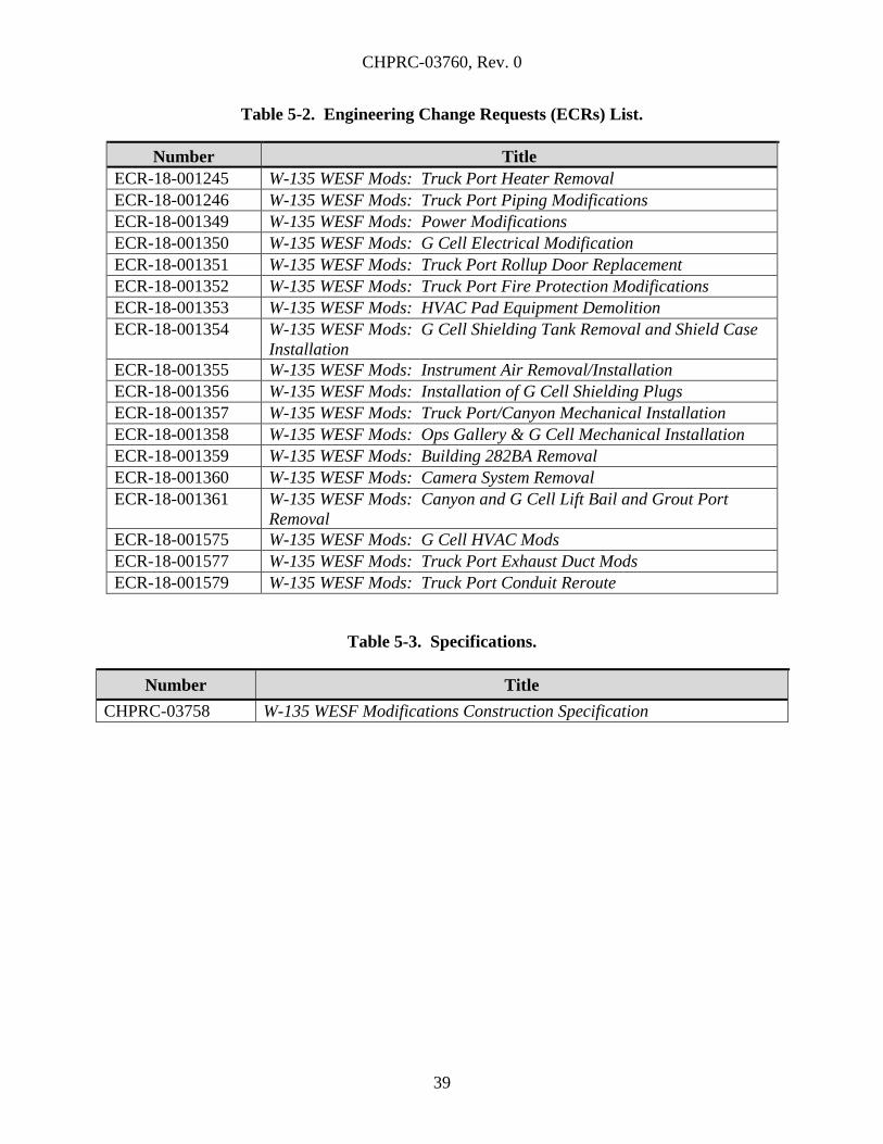
CHPRC-03760, Rev. 0
39
Table 5-2. Engineering Change Requests (ECRs) List.
Number Title
ECR-18-001245 W-135 WESF Mods: Truck Port Heater Removal
ECR-18-001246 W-135 WESF Mods: Truck Port Piping Modifications
ECR-18-001349 W-135 WESF Mods: Power Modifications
ECR-18-001350 W-135 WESF Mods: G Cell Electrical Modification
ECR-18-001351 W-135 WESF Mods: Truck Port Rollup Door Replacement
ECR-18-001352 W-135 WESF Mods: Truck Port Fire Protection Modifications
ECR-18-001353 W-135 WESF Mods: HVAC Pad Equipment Demolition
ECR-18-001354 W-135 WESF Mods: G Cell Shielding Tank Removal and Shield Case
Installation
ECR-18-001355 W-135 WESF Mods: Instrument Air Removal/Installation
ECR-18-001356 W-135 WESF Mods: Installation of G Cell Shielding Plugs
ECR-18-001357 W-135 WESF Mods: Truck Port/Canyon Mechanical Installation
ECR-18-001358 W-135 WESF Mods: Ops Gallery & G Cell Mechanical Installation
ECR-18-001359 W-135 WESF Mods: Building 282BA Removal
ECR-18-001360 W-135 WESF Mods: Camera System Removal
ECR-18-001361 W-135 WESF Mods: Canyon and G Cell Lift Bail and Grout Port
Removal
ECR-18-001575 W-135 WESF Mods: G Cell HVAC Mods
ECR-18-001577 W-135 WESF Mods: Truck Port Exhaust Duct Mods
ECR-18-001579 W-135 WESF Mods: Truck Port Conduit Reroute
Table 5-3. Specifications.
Number Title
CHPRC-03758 W-135 WESF Modifications Construction Specification
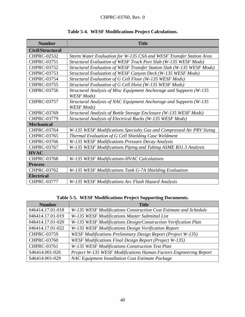
CHPRC-03760, Rev. 0
40
Table 5-4. WESF Modifications Project Calculations.
Number Title
Civil/Structural
CHPRC-02532 Storm Water Evaluation for W-135 CSA and WESF Transfer Station Area
CHPRC-03751 Structural Evaluation of WESF Truck Port Slab (W-135 WESF Mods)
CHPRC-03752 Structural Evaluation of WESF Transfer Station Slab (W-135 WESF Mods)
CHPRC-03753 Structural Evaluation of WESF Canyon Deck (W-135 WESF Mods)
CHPRC-03754 Structural Evaluation of G Cell Floor (W-135 WESF Mods)
CHPRC-03755 Structural Evaluation of G Cell Hoist (W-135 WESF Mods)
CHPRC-03756 Structural Analysis of Misc Equipment Anchorage and Supports (W-135
WESF Mods)
CHPRC-03757 Structural Analysis of NAC Equipment Anchorage and Supports (W-135
WESF Mods)
CHPRC-03769 Structural Analysis of Bottle Storage Enclosure (W-135 WESF Mods)
CHPRC-03779 Structural Analysis of Electrical Racks (W-135 WESF Mods)
Mechanical
CHPRC-03764 W-135 WESF Modifications Specialty Gas and Compressed Air PRV Sizing
CHPRC-03765 Thermal Evaluation of G Cell Shielding Case Weldment
CHPRC-03766 W-135 WESF Modifications Pressure Decay Analysis
CHPRC-03767 W-135 WESF Modifications Piping and Tubing ASME B31.3 Analysis
HVAC
CHPRC-03768 W-135 WESF Modifications-HVAC Calculations
Process
CHPRC-03762 W-135 WESF Modifications Tank G-7A Shielding Evaluation
Electrical
CHPRC-03777 W-135 WESF Modifications Arc Flash Hazard Analysis
Table 5-5. WESF Modifications Project Supporting Documents.
Title Number Title
046414.17.01-018 W-135 WESF Modifications Construction Cost Estimate and Schedule
046414.17.01-019 W-135 WESF Modifications Master Submittal List
046414.17.01-020 W-135 WESF Modifications Design/Construction Verification Plan
046414.17.01-022 W-135 WESF Modifications Design Verification Report
CHPRC-03759 WESF Modifications Preliminary Design Report (Project W-135)
CHPRC-03760 WESF Modifications Final Design Report (Project W-135)
CHPRC-03761 W-135 WESF Modifications Construction Test Plan
S46414.001-026 Project W-135 WESF Modifications Human Factors Engineering Report
S46414.001-029 NAC Equipment Installation Cost Estimate Package
CHPRC-03760, Rev. 0
41
6.0 APPLICABLE REQUIREMENTS
Applicable requirements have been passed down to sub-tier contractors as applicable and
implementation of those requirements was verified. The specific technical and quality
requirements, material certifications, qualification and certification of personnel, inspections,
examinations/testing and applicable QA records have been established and included in the final
design documents. Contractors have an effective program preventing the introduction of
suspect/counterfeit items through the design, procurement, fabrication, and modification process,
as described in DOE G 414.1-3, Suspect/Counterfeit Items Guide for Use with 10 CFR 830
Subpart A, Quality Assurance Requirements and DOE O 414.1B, Quality Assurance, and
DOE O 414.1D.
6.1 COST ESTIMATE AND PROJECT SCHEDULE
A Construction Cost Estimate and Schedule have been prepared which contain all cost and
schedule activities associated with procurement and construction.
A Work Breakdown Structure was used to organize the cost estimate and construction schedule.
The cost estimate was prepared utilizing the design media contained in this FDR as the technical
basis. Costs were derived using a quantity-based cost estimating approach by developing costs
for each estimate detail at the cost element level (examples of cost elements are labor, material,
equipment, etc.). Appropriate mark-ups, from labor productivity factors to sales tax, have also
been applied to arrive at a total cost for each estimate detail. A Cost Estimate Basis, which
explains the technical basis, organization, methodology, and assumptions used to create the
estimate, was also prepared.
Design decisions considered life-cycle costs and all other programmatic requirements, and
construction costs were balanced against operating and maintenance costs over the design life.
Selection of materials and equipment included the cost and availability of materials, parts, and
labor required for operation, maintenance, repair, and replacement.
The Construction Cost Estimate is provided under separate cover. See S&L
Report No. 046414.17.01-018, Project W-135 WESF Modifications Cost Estimate Package.
7.0 DESIGN COMPLETION STRATEGY/CONSTRUCTION ACQUISITION PLAN
CHPRC directed the Architect/Engineer through the final design phase, and will obtain
construction contractors, equipment vendors, and independent inspectors as required to execute
the WESF Modifications portion of Project W-135. CHPRC has and will continue to provide the
project management and engineering support to effectively and efficiently manage the work
scope. This includes management of all contractors (including cost, schedule, and technical
baselines), providing technical direction, reporting performance, preparation, and maintenance of
required project documentation, permitting, and QA-related activities.
CHPRC-03760, Rev. 0
42
CHPRC will utilize the final design to assemble bid packages to competitively solicit a contract
in order to perform all construction activities for the project.
CHPRC will also perform all construction management activities supporting the project. It is
anticipated that CHPRC will retain the same Architect/Engineer who prepared the final design to
perform engineering support during construction activities.
8.0 FINAL DESIGN ASSUMPTIONS
Design inputs are documented in Appendix C (Design Input Matrix) and in individual WESF
Modifications final design documents; e.g., engineering calculations. Due to the status of
available information regarding certain design interfaces, some design inputs are assumptions
that will require confirmation prior to procurement, fabrication, and construction. An example
relates to the WESF Modifications interface with the CSS Automatic Welding System (AWS);
design of the AWS not be completed until FY20.
In accordance relevant engineering procedures, CHPRC has identified and will control WESF
Modifications design inputs that are assumptions requiring confirmation prior to procurement,
fabrication, and construction. These assumptions are listed at the end of the FDC Compliance
Matrix (Appendix E). Consistent with PRC-STD-EN-40255, Functional Design Criteria, the W-
135 Project will publish the FDC Compliance Matrix including these assumptions as a
standalone document, and this document will undergo successive revisions as the listed
assumptions are confirmed.
9.0 REFERENCES
046414.17.01-018, 2018, Project W-135 WESF Modifications Cost Estimate Package, Rev. 0,
ARES ESD, a division of Sargent & Lundy Engineering Services, Inc., Richland,
Washington.
10 CFR 830, “Nuclear Safety Management,” Code of Federal Regulations, as amended.
10 CFR 835, “Occupational Radiation Protection,” Code of Federal Regulations, as amended.
10 CFR 851, “Worker Safety and Health Program,” Code of Federal Regulations, as amended.
29 CFR 1910, “Occupational Safety and Health Standards,” Code of Federal Regulations, as
amended.
29 CFR 1910.95, “Occupational Noise Exposure,” Code of Federal Regulations, as amended.
29 CFR 1926, “Safety and Health Regulations for Construction,” Code of Federal Regulations,
as amended.
CHPRC-03760, Rev. 0
43
ANSI N512, 1974, Protective Coatings (Paints) for the Nuclear Industry, American National
Standards Institute, Washington, District of Columbia.
ASME NQA-1, 2008 Edition and NQA-1a-2009 addenda, Quality Assurance Requirements for
Nuclear Facility Applications, American Society of Mechanical Engineers, New York,
New York.
CHPRC-00072, 2017, CHPRC Radiation Protection Program, Rev. 7, CH2M HILL Plateau
Remediation Company, Richland, Washington.
CHPRC-00073, 2017, CHPRC Radiological Control Manual, Rev. 12, CH2M HILL Plateau
Remediation Company, Richland, Washington.
CHPRC-00189, 2017, CH2M HILL Plateau Remediation Company Environmental Quality
Assurance Program Plan, Rev. 14, CH2M HILL Plateau Remediation Company,
Richland, Washington.
CHPRC-02236, 2017, Waste Encapsulation and Storage Facility Management of Cesium and
Strontium Capsules (Project W-135) Safety Design Strategy, Rev. 1, CH2M HILL
Plateau Remediation Company, Richland, Washington.
CHPRC-02252, 2017, Management of the Cesium and Strontium Capsules Project (W-135)
Functions and Requirements Document, Rev. 3, CH2M HILL Plateau Remediation
Company, Richland, Washington.
CHPRC-02264, MCSC Project Execution Plan for the Management of the Cesium and Strontium
Capsules (MCSC) Project (W-135), Rev. 2, CH2M HILL Plateau Remediation Company,
Richland, Washington.
CHPRC-02270, 2015, Structural Evaluation for Grouting the 225-B Building Hot Cells, Rev. 1,
CH2M HILL Plateau Remediation Company, Richland, Washington.
CHPRC-03011, WESF Modifications Functional Design Criteria (Project W-135), Rev. 3,
CH2M HILL Plateau Remediation Company, Richland, Washington.
CHPRC-03275, Capsule Storage Area and WESF Modifications Code of Record (Project
W-135), Rev. 0, CH2M HILL Plateau Remediation Company, Richland, Washington.
CHPRC-03299, Preliminary Fire Hazards Analysis for the Management of the Cesium and
Strontium Capsules Project [W-135], Rev. 0, CH2M HILL Plateau Remediation
Company, Richland, Washington.
CHPRC-03329, WESF Modifications Conceptual Design Report (Project W-135), Rev. 0,
CH2M HILL Plateau Remediation Company, Richland, Washington.
CHPRC-03452, 2018, W-135 WESF Modifications Test Plan, Rev. 1, CH2M HILL Plateau
Remediation Company, Richland, Washington.
CHPRC-03760, Rev. 0
44
CHPRC-03744, 2018, Preliminary Documented Safety Analysis for the Capsule Storage Area
(PDSA), Rev. 0, CH2M HILL Plateau Remediation Company, Richland, Washington.
CHPRC-03759, 2018, WESF Modifications Preliminary Design Report (Project W-135), Rev. 0,
CH2M HILL Plateau Remediation Company, Richland, Washington.
CHPRC-03831, 2018, W-135 Project Preliminary WESF Safety Equipment List, Rev. C, CH2M
HILL Plateau Remediation Company, Richland, Washington.
DOE G 413.3-1, 2008, Managing Design and Construction Using Systems Engineering for Use
with DOE O 413.3A, U.S. Department of Energy, Washington, D.C.
DOE O 413.3A/B, 2010, Program and Project Management for the Acquisition of Capital
Assets, U.S. Department of Energy, Washington, D.C.
DOE G 413.3-6A, 2011, High Performance Sustainability Building Requirements,
U.S. Department of Energy, Washington, D.C.
DOE G 414.1-3, 2004, Suspect/Counterfeit Items Guide for Use with 10 CFR 830 Subpart A,
Quality Assurance Requirements and DOE O 414.1B, Quality Assurance,
U.S. Department of Energy, Washington, D.C.
DOE O 414.1D, 2011, Quality Assurance, U.S. Department of Energy, Washington, D.C.
DOE O 430.1C, Real Property Asset Management, U.S. Department of Energy, Washington,
D.C.
DOE O 470.4B, 2011, Safeguards and Security Program, U.S. Department of Energy,
Washington, D.C.
DOE/RL-2012-47, 2013 Mission Need Statement for the Management of the Cesium and
Strontium Capsules, Rev. 0, U.S. Department of Energy, Richland, Washington.
DOE-STD-1089-99, 1999, Radiological Control, U.S. Department of Energy, Washington, D.C.
DOE-STD-1189, 2008, Integration of Safety into the Design Process, U.S. Department of
Energy, Washington, D.C.
HNF-8758, 2018, Waste Encapsulation and Storage Facility Documented Safety Analysis,
Rev. 12, CH2M HILL Plateau Remediation Company, Richland, Washington.
HNF-SD-WM-SEL-008, 2018, Waste Encapsulation and Storage Facility Safety Equipment List,
Rev. 28, CH2M HILL Plateau Remediation Company, Richland, Washington.
NAC 30059-110, 2018, G Cell Equipment Arrangement, MPC, Hanford, Rev. 0, NAC
International Inc., Norcross, Georgia.
NAC 30059-2001, 2018, Vertical Concrete Cask, MPC, Weight & C.G. Calculation, Rev. 4,
NAC International, Norcross, Georgia.
CHPRC-03760, Rev. 0
45
NAC 30059-2020, Structural Evaluation of the Pedestal and Accelerations for the CSS 9 Inch
Drop, Rev. 2, NAC International, Norcross, Georgia.
NAC 30059-Q-01, 2018, Quality Category Assessment for the Hanford MCSC Project Cask
Storage System, Rev. 2, NAC International Inc., Norcross, Georgia.
NFPA 13, 1994, Standard for the Installation of Sprinkler Systems, National Fire Protection
Association, Quincy, Massachusetts.
PRC-MP-MS-003, 2016, Integrated Safety Management System/Environmental Management
System Description, Rev. 4, Change 0, CH2M HILL Plateau Remediation Company,
Richland, Washington.
PRC-MP-SH-32219, 2017, 10 CFR 851 CHPRC Worker Safety and Health Program
Description, Rev. 3, Change 1, CH2M HILL Plateau Remediation Company, Richland,
Washington.
PRC-PRC-SH-40078, 2015, Contractor Safety Processes, Rev. 1, Change 9, CH2M HILL
Plateau Remediation Company, Richland, Washington.
PRC-PRO-EN-097, 2018, Engineering Design and Evaluation (Natural Phenomena Hazard),
Rev. 2, Change 0, CH2M HILL Plateau Remediation Company, Richland, Washington.
PRC-PRO-EN-40271, 2019, Engineering Design Process, Rev. 1, Chane 1, CH2M HILL
Plateau Remediation Company, Richland, Washington.
PRC-PRO-NS-700, 2018, Safety Basis Development, Rev. 1, Change 5, CH2M HILL Plateau
Remediation Company, Richland, Washington.
PRC-PRO-QA-259, 2017, Graded Approach, Rev. 2, Change 0, CH2M HILL Plateau
Remediation Company, Richland, Washington.
PRC-PRO-QA-33415, 2015, Structures, Systems, Components Cleaning/Cleanliness and
Foreign Material Exclusion, Rev. 0, Change 1, CH2M HILL Plateau Remediation
Company, Richland, Washington.
PRC-PRO-RP-1622, 2017, Radiological Design Review Process, Rev. 2, Change 0, CH2M
HILL Plateau Remediation Company, Richland, Washington.
PRC-STD-EN-40258, 2011, Preliminary/Final Design Report, Rev. 0, Change 1, CH2M HILL
Plateau Remediation Company, Richland, Washington.
RHO-R-022 (JABE-VITRO-01), 1971, Earthquake Analysis of the Waste Encapsulation
Facility, Prepared for Hanford Engineering Services by John A. Blume Associates, San
Francisco, California.
Statement of Work, Detailed Design for W-135 WESF Modifications and Capsule Storage Area,
Rev. 5, CH2M HILL Plateau Remediation Company, Richland, Washington.

CHPRC-03760, Rev. 0
46
WAC 173-303, “Dangerous Waste Regulations,” Washington Administrative Code, as amended.
W135-WESF-SK-C-001, 2017, W-135 Project General Arrangement Truck Port Concrete Pad,
Rev. B, Lucas Engineering and Management Services, Inc., Richland, Washington.
WHC-SD-WM-DA-219, 1996, WESF Structural Design Calculations, Rev. 0, Fluor Daniel
Northwest, Richland, Washington.

CHPRC-03760, Rev. 0
A-1
APPENDIX A
EQUIPMENT LIST
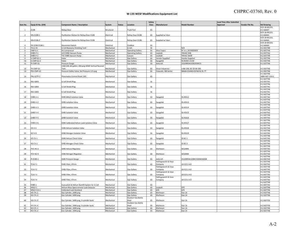
W‐135 WESF Modifications Equipment List
Item No. Equip ID No. (EIN) Component Name / Description System Status LocationSafety Class Manufacturer Model Number
Lead Time After Submittal Approval Vendor File No. Ref Drawing
1 D108 Rollup Door Structural Truck Port GSECR‐18‐001351 H‐2‐66407
2 MS‐D108‐1 Pushbutton Station for Rollup Door D108 Electrical Rollup Door D108 GS Supplied w/ doorECR‐18‐001351H‐2‐66464
3 MS‐D108‐2 Pushbutton Station for Rollup Door D108 Electrical Rollup Door D108 GS Supplied w/ doorECR‐18‐001351H‐2‐66464
4 DS‐225B‐D108‐1 Disconnect Switch Electrical Outdoor GSECR‐18‐001351H‐2‐66464
5 TK‐G‐7A G Cell Recovery Shielding Tank Mechanical G Cell SS N/A H‐2‐8377606 CMP‐G‐1 Air Compressor Mechanical Operating Gallery GS Atlas Copco SF 11+, 8153602829 H‐2‐8377467 EHBS‐P‐1 UCS EHBS Vacuum Pump Mechanical Operating Gallery GS Leybold TRIVAC D4B H‐2‐8377628 EHBS‐P‐2 TSC EHBS Vacuum Pump Mechanical Canyon GS Leybold TRIVAC D65B H‐2‐8377499 V‐CMP‐G1‐1 Valve Mechanical Ops Gallery GS Vendor Supplied Vendor Supplied H‐2‐83774610 V‐CMP‐G1‐2 Valve Mechanical Ops Gallery GS Swagelok SS‐BVM2‐C3‐SH H‐2‐83774611 PI‐CMP‐G1 Pressure Gauge Mechanical Ops Gallery GS Ashcroft 251009SWL02B200#XC4 H‐2‐837746
12 TK‐CMP‐G1LV60‐200, 60 gallon, 200 psig ASME Vertical Receiver Tank Mechanical Ops Gallery GS Silvan Industries LV60‐200, 82‐20‐60‐200 H‐2‐837746
13 PSV‐CMP‐G1 Pressure Safety Valve, Set Pressure 115 psig Mechanical Ops Gallery GS Flowsafe, F80 Series S846B‐01MN0‐01FN0‐SL‐SL‐TT H‐2‐837746
14 PNL‐G/TP‐2 Pneumatics Control Panel, GFE Mechanical Ops Gallery GSH‐2‐8377461806‐HEF‐134‐G
15 RSE‐G003 G Cell Shield Plug Mechanical Ops Gallery SSH‐2‐837746H‐2‐837761
16 RSE‐G004 G Cell Shield Plug Mechanical Ops Gallery SSH‐2‐837746H‐2‐837761
17 RSE‐G005 G Cell Shield Plug Mechanical Ops Gallery SSH‐2‐837746H‐2‐837761
18 EHBS‐V‐1 EHBS MSLD Isolation Valve Mechanical Ops Gallery GS Swagelok SS‐45S12H‐2‐837746H‐2‐837762
19 EHBS‐V‐2 EHBS Isolation Valve Mechanical Ops Gallery GS Swagelok SS‐45S13H‐2‐837746H‐2‐837762
20 EHBS‐V‐3 EHBS Isolation Valve Mechanical Ops Gallery GS Swagelok SS‐45S14H‐2‐837746H‐2‐837762
21 EHBS‐V‐4 EHBS Isolation Valve Mechanical Ops Gallery GS Swagelok SS‐45S15H‐2‐837746H‐2‐837762
22 EHBS‐V‐5 EHBS Isolation Valve Mechanical Ops Gallery GS Swagelok SS‐45S16H‐2‐837746H‐2‐837762
23 EHBS‐V‐6 EHBS Calibrated Helium Leak Isolation Valve Mechanical Ops Gallery GS Swagelok SS‐45S17H‐2‐837746H‐2‐837762
24 HE‐V‐3 EHBS Helium Isolation Valve Mechanical Ops Gallery GS Swagelok SS‐45S18H‐2‐837746H‐2‐837762
25 N2‐V‐3 EHBS Nitrogen Isolation Valve Mechanical Ops Gallery GS Swagelok SS‐45S19H‐2‐837746H‐2‐837762
26 HE‐CV‐1 EHBS Helium Check Valve Mechanical Ops Gallery GS Swagelok SS‐8C‐1H‐2‐837746H‐2‐837762
27 N2‐CV‐1 EHBS Nitrogen Check Valve Mechanical Ops Gallery GS Swagelok SS‐8C‐2H‐2‐837746H‐2‐837762
28 PVC‐HE‐3 EHBS Helium Regulator Mechanical Ops Gallery GS Matheson SEQ3494H‐2‐837746H‐2‐837762
29 PCV‐N2‐3 EHBS Nitrogen Regulator Mechanical Ops Gallery GS Matheson SEQ3494H‐2‐837746H‐2‐837762
30 PI‐EHBS‐1 EHBS Pressure Gauge Mechanical Ops Gallery GS Ashcroft 251009SWL02BXC430IMV&30#H‐2‐837746H‐2‐837762
31 TCA‐F‐1 EHBS Filter, 47mm Mechanical Ops Gallery GSHollingsworth & Vose Company LB‐5211 A‐O
H‐2‐837746H‐2‐837762
32 TCA‐F‐2 EHBS Filter, 47mm Mechanical Ops Gallery GSHollingsworth & Vose Company LB‐5211 A‐O
H‐2‐837746H‐2‐837762
33 TCA‐F‐3 EHBS Filter, 47mm Mechanical Ops Gallery GSHollingsworth & Vose Company LB‐5211 A‐O
H‐2‐837746H‐2‐837762
34 TCA‐F‐4 EHBS Filter, 47mm Mechanical Ops Gallery GSHollingsworth & Vose Company LB‐5211 A‐O
H‐2‐837746H‐2‐837762
35 EHBS‐1 Evacuation & Helium Backfill System for G Cell Mechanical Ops Gallery GSH‐2‐837746H‐2‐837762
36 MSLD‐1 Helium Mass Spectrometer Leak Detector Mechanical Ops Gallery GS Leybold GFE H‐2‐83774637 MSLD‐CLS‐1 Calibrated Leak Standard Mechanical Ops Gallery GS GFE GFE H‐2‐83774638 HE‐CYL‐1 Gas Cylinder, 2490 psig Mechanical Ops Gallery GS Matheson Size 1A H‐2‐83774639 HE‐CYL‐2 Gas Cylinder, 2490 psig Mechanical Ops Gallery GS Matheson Size 1A H‐2‐837746
40 HE‐CYL‐3 Gas Cylinder, 2490 psig, 3‐cylinder bank MechanicalOutdoor Gas Bottle Shed GS Matheson Size 1A H‐2‐837750
41 HY‐CYL‐4 Gas Cylinder, 2490 psig, 3‐cylinder bank MechanicalOutdoor Gas Bottle Shed GS Matheson Size 1A H‐2‐837750
42 N2‐CYL‐1 Gas Cylinder, 2490 psig Mechanical Ops Gallery GS Matheson Size 1A H‐2‐83774643 N2‐CYL‐2 Gas Cylinder, 2490 psig Mechanical Ops Gallery GS Matheson Size 1A H‐2‐837746
CHPRC-03760, Rev. 0
A-2
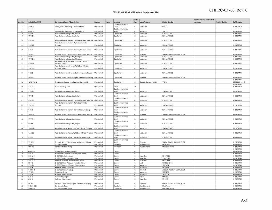
W‐135 WESF Modifications Equipment List
Item No. Equip ID No. (EIN) Component Name / Description System Status LocationSafety Class Manufacturer Model Number
Lead Time After Submittal Approval Vendor File No. Ref Drawing
44 AR‐CYL‐1 Gas Cylinder, 2490 psig, 3‐cylinder bank MechanicalOutdoor Gas Bottle Shed GS Matheson Size 1A H‐2‐837750
45 AR‐CYL‐2 Gas Cylinder, 2490 psig, 3‐cylinder bank MechanicalOutdoor Gas Bottle Shed GS Matheson Size 1A H‐2‐837750
46 PCV‐HE‐1 Auto Switchover Regulator, Helium Mechanical Ops Gallery GS Matheson 524‐A28T7ALC H‐2‐83774647 PCV‐HE‐2 Auto Switchover Regulator, Helium Mechanical Ops Gallery GS Matheson 524‐A28T7ALC H‐2‐837746
48 PI‐HE‐1A Auto Switchover, Helium, Left Side Cylinder Pressure Mechanical Ops Gallery GS Matheson 524‐A28T7ALC H‐2‐837746
49 PI‐HE‐1BAuto Switchover, Helium, Right Side Cylinder Pressure Mechanical Ops Gallery GS Matheson 524‐A28T7ALC H‐2‐837746
50 PI‐HE‐2 Auto Switchover, Helium, Delivery Pressure Gauge Mechanical Ops Gallery GS Matheson 524‐A28T7ALC H‐2‐837746
51 PSV‐HE‐2 Pressure Safety Valve, Helium, Set Pressure 50 psig Mechanical Ops Gallery GS Flowsafe S842M‐05MN0‐05FN0‐SL‐SL‐TT H‐2‐83774652 PCV‐N2‐1 Auto Switchover Regulator, Nitrogen Mechanical Ops Gallery GS Matheson 524‐A28T7ALC H‐2‐83774653 PCV‐N2‐2 Auto Switchover Regulator, Nitrogen Mechanical Ops Gallery GS Matheson 524‐A28T7ALC H‐2‐837746
54 PI‐N2‐1AAuto Switchover, Nitrogen, Left Side Cylinder Pressure Gauge Mechanical Ops Gallery GS Matheson 524‐A28T7ALC H‐2‐837746
55 PI‐N2‐1BAuto Switchover, Nitrogen, Right Side Cylinder Pressure Gauge Mechanical Ops Gallery GS Matheson 524‐A28T7ALC H‐2‐837746
56 PI‐N2‐2 Auto Switchover, Nitrogen, Deliver Pressure Gauge Mechanical Ops Gallery GS Matheson 524‐A28T7ALC H‐2‐837746
57 PSV‐N2‐2 Pressure Safety Valve, Nitrogen, Set Pressure 50 psig Mechanical Ops Gallery GS Flowsafe S842M‐05MN0‐05FN0‐SL‐SL‐TT H‐2‐837746
58 P‐VAC‐TCA‐1 Pneumatics Control Panel Vacuum Pump, GFE Mechanical Ops Gallery GS Gardner Denver Picolino VTE‐8H‐2‐8377461806‐HEF‐134‐G
59 TK‐G‐7A G Cell Shielding Tank Mechanical G Cell SSH‐2‐837747H‐2‐837760
60 PCV‐HE‐5 Auto Switchover Regulator, Helium MechanicalOutdoor Gas Bottle Shed GS Matheson 524‐A68T7ALC H‐2‐837750
61 PCV‐HE‐6 Auto Switchover Regulator, Helium MechanicalOutdoor Gas Bottle Shed GS Matheson 524‐A68T7ALC H‐2‐837750
62 PI‐HE‐5A Auto Switchover, Helium, Left Side Cylinder Pressure MechanicalOutdoor Gas Bottle Shed GS Matheson 524‐A68T7ALC H‐2‐837750
63 PI‐HE‐5BAuto Switchover, Helium, Right Side Cylinder Pressure Mechanical
Outdoor Gas Bottle Shed GS Matheson 524‐A68T7ALC H‐2‐837750
64 PI‐HE‐6 Auto Switchover, Helium, Deliver Pressure Gauge MechanicalOutdoor Gas Bottle Shed GS Matheson 524‐A68T7ALC H‐2‐837750
65 PSV‐HE‐6 Pressure Safety Valve, Helium, Set Pressure 50 psig MechanicalOutdoor Gas Bottle Shed GS Flowsafe S842M‐05MN0‐05FN0‐SL‐SL‐TT H‐2‐837750
66 PCV‐AR‐1 Auto Switchover Regulator, Argon MechanicalOutdoor Gas Bottle Shed GS Matheson 524‐A68T7ALC H‐2‐837750
67 PCV‐AR‐2 Auto Switchover Regulator, Argon MechanicalOutdoor Gas Bottle Shed GS Matheson 524‐A68T7ALC H‐2‐837750
68 PI‐AR‐1A Auto Switchover, Argon, Left Side Cylinder Pressure MechanicalOutdoor Gas Bottle Shed GS Matheson 524‐A68T7ALC H‐2‐837750
69 PI‐AR‐1B Auto Switchover, Argon, Right Side Cylinder Pressure MechanicalOutdoor Gas Bottle Shed GS Matheson 524‐A68T7ALC H‐2‐837750
70 PI‐AR‐2 Auto Switchover, Argon, Deliver Pressure Gauge MechanicalOutdoor Gas Bottle Shed GS Matheson 524‐A68T7ALC H‐2‐837750
71 PSV‐AR‐2 Pressure Safety Valve, Argon, Set Pressure 50 psig MechanicalOutdoor Gas Bottle Shed GS Flowsafe S842M‐05MN0‐05FN0‐SL‐SL‐TT H‐2‐837750
72 TK‐TP‐1 Condensate Tank Mechanical Truck Port GS Blue Diamond MultiTank H‐2‐83774873 P‐TK‐TP1 Condensate Tank Pump Mechanical Truck Port GS Blue Diamond MaxiBlue Pump H‐2‐837748
74 HRA‐DTS‐1 DTS Cable/Hose Reel Assembly Mechanical Canyon GSH‐2‐837749H‐2‐837764
75 EHBS‐2 Evacuation & Helium Backfill System for TSC Mechanical Canyon GS H‐2‐83774976 EHBS‐V‐11 EHBS TSC Isolation Valve Mechanical Canyon GS Swagelok SS‐65TS16 H‐2‐83774977 EHBS‐V‐12 EHBS TSC Helium Isolation Valve Mechanical Canyon GS Swagelok SS‐65TS17 H‐2‐83774978 EHBS‐V‐13 EHBS TSC Vacuum Pump Isolation Valve Mechanical Canyon GS Swagelok SS‐65TS18 H‐2‐83774979 TSC‐F‐1 EHBS TSC Filter ‐ Vacuum Pump Discharge Mechanical Canyon GS Mott GSP515H3FF33 H‐2‐83774980 PCV‐HE‐8 EHBS TSC Pressure Control Valve, Helium Mechanical Canyon GS Matheson SEQ3494 H‐2‐83774981 PI‐HE‐8 EHBS TSC Pressure Gauge Mechanical Canyon GS Matheson SEQ3494 H‐2‐83774982 PI‐EHBS‐2 EHBS TSC Pressure Gauge Mechanical Canyon GS Ashcroft 251009SWL04LXC430IMV&30# H‐2‐83774983 PCV‐AR‐3 Regulator, Argon Mechanical Canyon GS Matheson SEQ3203 H‐2‐83774984 PI‐AR‐3 Pressure Gauge, Argon Mechanical Canyon GS Matheson SEQ3203 H‐2‐83774985 FI‐AR‐3 Flow Meter, Argon Mechanical Canyon GS Victor FM‐155 H‐2‐83774986 AR‐V‐4 Isolation Valve, Argon Mechanical Canyon GS Swagelok SS‐45S8 H‐2‐837749
87 PSV‐AR‐3 Pressure Safety Valve, Argon, Set Pressure 25 psig Mechanical Canyon GS Flowsafe S842M‐05MN0‐05FN0‐SL‐SL‐TT H‐2‐83774988 TK‐CMP‐G1‐2 Condensate Tank Mechanical Ops Gallery GS Blue Diamond MultiTank H‐2‐83774689 P‐CMP‐G1 Condensate Tank Pump Mechanical Ops Gallery GS Blue Diamond MaxiBlue Pump H‐2‐837746
CHPRC-03760, Rev. 0
A-3
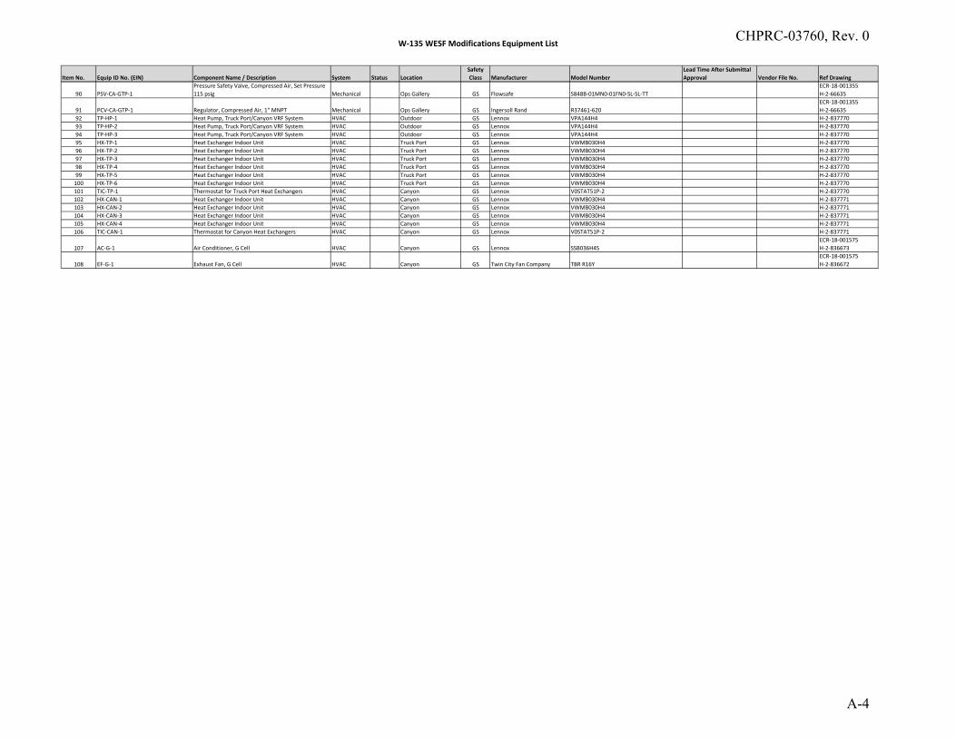
W‐135 WESF Modifications Equipment List
Item No. Equip ID No. (EIN) Component Name / Description System Status LocationSafety Class Manufacturer Model Number
Lead Time After Submittal Approval Vendor File No. Ref Drawing
90 PSV‐CA‐GTP‐1Pressure Safety Valve, Compressed Air, Set Pressure 115 psig Mechanical Ops Gallery GS Flowsafe S848B‐01MN0‐01FN0‐SL‐SL‐TT
ECR‐18‐001355H‐2‐66635
91 PCV‐CA‐GTP‐1 Regulator, Compressed Air, 1" MNPT Mechanical Ops Gallery GS Ingersoll Rand R37461‐620ECR‐18‐001355H‐2‐66635
92 TP‐HP‐1 Heat Pump, Truck Port/Canyon VRF System HVAC Outdoor GS Lennox VPA144H4 H‐2‐83777093 TP‐HP‐2 Heat Pump, Truck Port/Canyon VRF System HVAC Outdoor GS Lennox VPA144H4 H‐2‐83777094 TP‐HP‐3 Heat Pump, Truck Port/Canyon VRF System HVAC Outdoor GS Lennox VPA144H4 H‐2‐83777095 HX‐TP‐1 Heat Exchanger Indoor Unit HVAC Truck Port GS Lennox VWMB030H4 H‐2‐83777096 HX‐TP‐2 Heat Exchanger Indoor Unit HVAC Truck Port GS Lennox VWMB030H4 H‐2‐83777097 HX‐TP‐3 Heat Exchanger Indoor Unit HVAC Truck Port GS Lennox VWMB030H4 H‐2‐83777098 HX‐TP‐4 Heat Exchanger Indoor Unit HVAC Truck Port GS Lennox VWMB030H4 H‐2‐83777099 HX‐TP‐5 Heat Exchanger Indoor Unit HVAC Truck Port GS Lennox VWMB030H4 H‐2‐837770100 HX‐TP‐6 Heat Exchanger Indoor Unit HVAC Truck Port GS Lennox VWMB030H4 H‐2‐837770101 TIC‐TP‐1 Thermostat for Truck Port Heat Exchangers HVAC Canyon GS Lennox V0STAT51P‐2 H‐2‐837770102 HX‐CAN‐1 Heat Exchanger Indoor Unit HVAC Canyon GS Lennox VWMB030H4 H‐2‐837771103 HX‐CAN‐2 Heat Exchanger Indoor Unit HVAC Canyon GS Lennox VWMB030H4 H‐2‐837771104 HX‐CAN‐3 Heat Exchanger Indoor Unit HVAC Canyon GS Lennox VWMB030H4 H‐2‐837771105 HX‐CAN‐4 Heat Exchanger Indoor Unit HVAC Canyon GS Lennox VWMB030H4 H‐2‐837771106 TIC‐CAN‐1 Thermostat for Canyon Heat Exchangers HVAC Canyon GS Lennox V0STAT51P‐2 H‐2‐837771
107 AC‐G‐1 Air Conditioner, G Cell HVAC Canyon GS Lennox SSB036H4SECR‐18‐001575H‐2‐836673
108 EF‐G‐1 Exhaust Fan, G Cell HVAC Canyon GS Twin City Fan Company TBR R16YECR‐18‐001575H‐2‐836672
CHPRC-03760, Rev. 0
A-4

CHPRC-03760, Rev. 0
B-1
APPENDIX B
HUMAN FACTORS ENGINEERING REPORT
PROJECT W-135 WESF MODIFICATIONS
HUMAN FACTORS ENGINEERING REPORT
prepared for
CH2M HILL PLATEAU REMEDIATION COMPANY Subcontract No. 64824-001
Report No. S46414.001-026
Revision 0
May 2019
prepared by
ARES ESD,
A DIVISION OF SARGENT & LUNDY
ENGINEERING SERVICES, INC. 1100 Jadwin Avenue, Suite 400
Richland, Washington 99352
(509) 946-3300
CHPRC-03760, Rev. 0
B-2
PROJECT W-135 WESF MODIFICATIONS HUMAN
FACTORS ENGINEERING REPORT
Report No. S46414.001-026, Rev. 0
May 2019
Page i
PROJECT W-135 WESF MODIFICATIONS
HUMAN FACTORS ENGINEERING REPORT
prepared for
CH2M HILL PLATEAU REMEDIATION COMPANY Subcontract No. 64824-001
Report No. S46414.001-026
Revision 0
May 2019
Prepared by: 5/8/2019
Bruce D. Groth Date
Reviewed by: 5/8/2019
Lori B. Weidner, P.E. Date
Approved by: 5/8/2019
Denis P. DeVine Date
CHPRC-03760, Rev. 0
B-3
PROJECT W-135 WESF MODIFICATIONS HUMAN
FACTORS ENGINEERING REPORT
Report No. S46414.001-026, Rev. 0
May 2019
Page ii
REVISION DESCRIPTION
Rev.
Reason for
Revision Change Description
Affected Pages
(Page/Sec./Para.) Date
0 Initial Issue All pages 5/8/2019
CHPRC-03760, Rev. 0
B-4
PROJECT W-135 WESF MODIFICATIONS HUMAN
FACTORS ENGINEERING REPORT
Report No. S46414.001-026, Rev. 0
May 2019
Page iii
TABLE OF CONTENTS
1.0 INTRODUCTION AND BACKGROUND ....................................................................................1
2.0 PURPOSE AND SCOPE .................................................................................................................1
3.0 DESIGN DESCRIPTION ................................................................................................................2
3.1 Applicable Drawings Reviewed ................................................................................................2
4.0 GENERAL HUMAN FACTORS CRITERIA AND CONSIDERATIONS ...................................3
4.1 Radiation Exposure ....................................................................................................................3
4.2 Lighting ......................................................................................................................................3
4.3 Instrumentation and Control ......................................................................................................3
4.4 Other Hazards to Personnel .......................................................................................................3
4.5 Heat Stress .................................................................................................................................3
5.0 REFERENCES ................................................................................................................................4
Appendices
Appendix A
Detailed Design Considerations for Human Factors Engineering Checklist
CHPRC-03760, Rev. 0
B-5
PROJECT W-135 WESF MODIFICATIONS HUMAN
FACTORS ENGINEERING REPORT
Report No. S46414.001-026, Rev. 0
May 2019
Page iv
Acronyms
ALARA As Low as Reasonably Achievable
ATMS Ambient Temperature Monitoring System
AWS Automated Welding System
CCTV Closed-Circuit Television
CSA Capsule Storage Area
CSS Cask Storage System
DTS Dry Transfer System
HEPA High-Efficiency Particulate Air
HVAC Heating, Ventilation, and Air Conditioning
I&C Instrumentation and Control
IEEE Institute of Electrical and Electronics Engineers
IES Illuminating Engineering Society
MCSC Management of Cesium and Strontium Capsule
NAC NAC International
NUREG U.S. Nuclear Regulatory Commission Regulation
P&ID Piping and Instrumentation Drawing
PPE Personal Protective Equipment
TV Television
UHP Ultra-High Purity
VCC Vertical Concrete Cask
VCT Vertical Cask Transporter
WESF Waste Encapsulation Storage Facility
CHPRC-03760, Rev. 0
B-6
PROJECT W-135 WESF MODIFICATIONS HUMAN
FACTORS ENGINEERING REPORT
Report No. S46414.001-026, Rev. 0
May 2019
Page 1
1.0 INTRODUCTION AND BACKGROUND
The Management of Cesium and Strontium Capsules (MCSC) Project (W-135) will fill the capability
gap for interim storage of cesium and strontium capsules currently stored underwater at the Waste
Encapsulation and Storage Facility (WESF). The scope of Project W-135 is consistent with
DOE/RL-2012-47, Mission Need Statement for the Management of the Cesium and Strontium Capsules.
The project will provide the capabilities necessary to transfer the capsules from the WESF pool cell to a
Cask Storage System (CSS) which will be located in a new Capsule Storage Area (CSA). The CSS will
safely and compliantly store the 1,936 capsules until a capsule disposal option is available in the future.
This report addresses the WESF Modifications portion of Project W-135, which consists of the design
and construction of the following key elements:
Modifications to the WESF Truck Port to accommodate a fully loaded CSS and other associated
design criteria equipment and for the ventilation in the Truck Port to be capable of maintaining a
temperature below 80º F;
Modifications to the WESF Canyon area to support needed equipment and cover block laydown
area and utilities to the CSS equipment and for the ventilation in the Canyon to be capable of
maintaining a temperature below 80º F
Modifications to the WESF G Cell for installation of CSS equipment and for the ventilation in G
Cell to be capable of maintaining a temperature below 80º F;
Modifications to the WESF Operating Gallery to support needed equipment;
Installation of Ambient Temperature Monitoring System (ATMS)
CSS equipment installation to include structural fixing of equipment and making all service
connections; and
Location for temporary storage of failed capsules within G Cell.
2.0 PURPOSE AND SCOPE
The purpose of this report is to document a human factors evaluation of the WESF Modification portion
of Project W-135 as required by CHPRC-03011, WESF Modifications Functional Design Criteria
(Project W-135). Section 6.3 of CHPRC-03011 states that:
“The design or the selection of equipment to be operated and maintained by personnel
shall include the application of human factors engineering criteria together with other
appropriate design criteria.
CHPRC-03760, Rev. 0
B-7
PROJECT W-135 WESF MODIFICATIONS HUMAN
FACTORS ENGINEERING REPORT
Report No. S46414.001-026, Rev. 0
May 2019
Page 2
“Decisions concerning which system functions to allocate to the human versus the
machine shall be determined by analyses of system functions required, impact of
error or no action on safety, and a comparison of human capabilities and equipment
capabilities for the separate system functions.
“Systems, subsystems, and equipment shall consider the human engineering
guidelines of DOE-HDBK-1140, Human Factors/Ergonomics Handbook for the
Design for Ease of Maintenance, U.S. Nuclear Regulatory Commission Regulation
(NUREG)-0700, and Institute of Electrical and Electronics Engineers (IEEE)
Standard 1023, IEEE Recommended Practice for the Application of Human Factors
Engineering to Systems, Equipment, and Facilities of Nuclear Power Generating
Stations and Other Nuclear Facilities.
“A human factors evaluation shall be performed and documented on the completed
design.”
A checklist based on NUREG-0700, Human-System Interface Design Review Guidelines, was initially
used to review the design. This checklist is more comprehensive than IEEE 1023-2004 and covers
similar material. DOE-HDBK-1140 was canceled by the U.S. Department of Energy in January of
2017, but aspects of it are considered in the design for maintainability. However, doing an initial
assessment with this checklist showed that it is largely not applicable as it is focused on instrumentation
and controls (I&C) which are not included in the WESF Modifications with the exception of the ATMS
which is strictly a temperature monitoring system at various locations with a local alarm annunciator in
the control room. Therefore, another human factors checklist from the Hanford Tank Farms was
utilized. This checklist is from TFC-ENG-STD-01, Human Factors in Design, and was utilized as most
appropriate to the level of complexity in the design and construction of modifications to WESF for
installing the CSS. Operations of certain modifications are also considered, but operations of the CSS
are out of the scope of this design effort and associated human factors analysis.
3.0 DESIGN DESCRIPTION
As stated previously, the WESF Modifications portion of Project W-135 consists of design and
construction of the modifications to the Truck Port, Canyon, G Cell, CSS Equipment Installation,
ATMS, and a failed capsule storage location in G Cell. Additional details are provided in the CHPRC-
03760, Waste Encapsulation Storage Facility Modifications Final Design Report (Project W-135).
3.1 Applicable Drawings Reviewed
The drawings listed on H-2-837725, WESF Modifications Drawing List and Title Sheet, were reviewed
as part of this human factors evaluation.
CHPRC-03760, Rev. 0
B-8
PROJECT W-135 WESF MODIFICATIONS HUMAN
FACTORS ENGINEERING REPORT
Report No. S46414.001-026, Rev. 0
May 2019
Page 3
4.0 GENERAL HUMAN FACTORS CRITERIA AND CONSIDERATIONS
The completed human factors checklist used is contained in Appendix A. Human factors aspects of the
WESF Modification that it addresses primarily include minimizing exposure to radiation and chemicals,
and general criteria associated with accessibility to this equipment. Tripping, sharp edges, and other
potential hazards are also addressed. Details on these human factor considerations in the CSA design
are described in more detail in the subsections that follow.
4.1 Radiation Exposure
In general, shielding has been shown to be adequate with a dose rate requirement in manned spaces of
less than 0.5 mR/hr. There are however, two penetrations in the G-Cell shown on Drawings H-2-
837761 and H-2-837762 that have not been addressed in the shielding calculation CHPRC-03762, Tank
G-7A Shielding Evaluation, or other shielding calculation. These penetrations may need to be addressed
using Monte Carlo modeling.
No as-low-as-reasonably-achievable (ALARA) assessment has yet been conducted for removal of the
20 ft x 30 ft steel plate over the radioactively contaminated ground as shown on Drawing H-2-837729.
4.2 Lighting
No lighting modifications have been performed as part of the WESF Modification, and thus none of
these human factors associated with them are applicable.
4.3 Instrumentation and Control
No human factors comments were noted relative to the ATMS. This is a simple panel with a readout on
the Temperature Recorder and a Clear Fault and Reset button on the counsel.
4.4 Other Hazards to Personnel
There is a small air compressor located in the operating gallery as shown on Drawing H-2-837746. This
was thought to be a potential noise concern, but the air compressor specified is an Atlas Copco SF11+
which has a published noise level of 63 db. This is well below the maximum allowable noise level of
90 db required by Occupational Safety and Health Standards 29 CFR 1910.95, “Occupational Noise
Exposure.”
4.5 Heat Stress
The Truck Port was the location where there was a potential for high heat stress of operators due to high
ambient temperatures and the presence of a large heat source when loading cesium capsules into the
VCC. Report No. 046414.18.01-021, Project W-135, WESF Modifications Ventilation Study, addresses
this concern with recommendations for modifications to the Truck Port ventilation to maintain the space
temperature below 80º F during design conditions. The design modifications have been designed to
CHPRC-03760, Rev. 0
B-9
PROJECT W-135 WESF MODIFICATIONS HUMAN
FACTORS ENGINEERING REPORT
Report No. S46414.001-026, Rev. 0
May 2019
Page 4
maintain the Truck Port and Canyon at <80º F as measured at the VCC inlet vents as shown by
calculation CHPRC-03768, W-135 WESF Modifications – HVAC Calculations.
5.0 REFERENCES
29 CFR 1910.95, “Occupational Noise Exposure,” Code of Federal Regulations, as amended.
046414.18.01-021, 2018, Project W-135, WESF Modifications Ventilation Study, Rev. 0, ARES
Corporation, Richland, Washington.
30059-110, 2018, G Cell Equipment Arrangement, MPC, Hanford, Rev. 0, NAC International Inc.,
Norcross, Georgia.
CHPRC-03011, 2019, WESF Modifications Functional Design Criteria (Project W-135), Rev. 3,
CH2M HILL Plateau Remediation Company, Richland, Washington.
CHPRC-03760, Waste Encapsulation Storage Facility Modifications Final Design Report (Project
W-135), Rev. 0, CH2M HILL Plateau Remediation Company, Richland, Washington.
CHPRC-03762, 2019, Tank G-7A Shielding Evaluation, Rev. 0, CH2M HILL Plateau Remediation
Company, Richland, Washington.
CHPRC-03768, 2019, W-135 WESF Modifications – HVAC Calculations, Rev. 0, CH2M HILL Plateau
Remediation Company, Richland, Washington.
DOE-HDBK-1140, 2001, Human Factors/Ergonomics Handbook for the Design for Ease of
Maintenance, canceled January 13, 2017, U.S. Department of Energy, Washington, D.C.
DOE/RL-2012-47, 2015, Mission Need Statement for the Management of the Cesium and Strontium
Capsules, Rev. 6, U.S. Department of Energy, Richland, Washington.
IEEE 1023-2004, IEEE Recommended Practice for the Application of Human Factors Engineering to
Systems, Equipment, and Facilities of Nuclear Power Generating Stations and Other Nuclear
Facilities, Institute of Electrical and Electronics Engineers, New York, New York.
NUREG-0700, 2002, Human-System Interface Design Review Guidelines, Rev. 2, Office of Nuclear
Regulatory Research, U.S. Nuclear Regulatory Commission, Washington, D.C.
TFC-ENG-STD-01, 2016, Human Factors in Design, Rev. A-7, Washington River Protection Solutions,
LLC, Richland, Washington.
CHPRC-03760, Rev. 0
B-10
PROJECT W-135 WESF MODIFICATIONS HUMAN
FACTORS ENGINEERING REPORT
Report No. S46414.001-026, Rev. 0
May 2019
Page A-1
APPENDIX A
DETAILED DESIGN CONSIDERATIONS FOR HUMAN FACTORS
ENGINEERING CHECKLIST
CHPRC-03760, Rev. 0
B-11
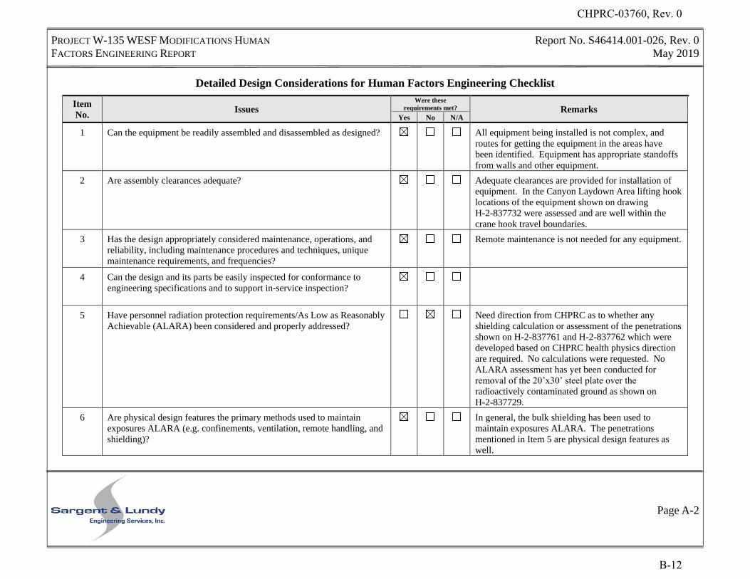
PROJECT W-135 WESF MODIFICATIONS HUMAN
FACTORS ENGINEERING REPORT
Report No. S46414.001-026, Rev. 0
May 2019
Page A-2
Detailed Design Considerations for Human Factors Engineering Checklist
Item
No. Issues
Were these
requirements met? Remarks Yes No N/A
1 Can the equipment be readily assembled and disassembled as designed? All equipment being installed is not complex, and
routes for getting the equipment in the areas have
been identified. Equipment has appropriate standoffs
from walls and other equipment.
2 Are assembly clearances adequate? Adequate clearances are provided for installation of
equipment. In the Canyon Laydown Area lifting hook
locations of the equipment shown on drawing
H-2-837732 were assessed and are well within the
crane hook travel boundaries.
3 Has the design appropriately considered maintenance, operations, and
reliability, including maintenance procedures and techniques, unique
maintenance requirements, and frequencies?
Remote maintenance is not needed for any equipment.
4 Can the design and its parts be easily inspected for conformance to
engineering specifications and to support in-service inspection?
5 Have personnel radiation protection requirements/As Low as Reasonably
Achievable (ALARA) been considered and properly addressed?
Need direction from CHPRC as to whether any
shielding calculation or assessment of the penetrations
shown on H-2-837761 and H-2-837762 which were
developed based on CHPRC health physics direction
are required. No calculations were requested. No
ALARA assessment has yet been conducted for
removal of the 20’x30’ steel plate over the
radioactively contaminated ground as shown on
H-2-837729.
6 Are physical design features the primary methods used to maintain
exposures ALARA (e.g. confinements, ventilation, remote handling, and
shielding)?
In general, the bulk shielding has been used to
maintain exposures ALARA. The penetrations
mentioned in Item 5 are physical design features as
well.
CHPRC-03760, Rev. 0
B-12
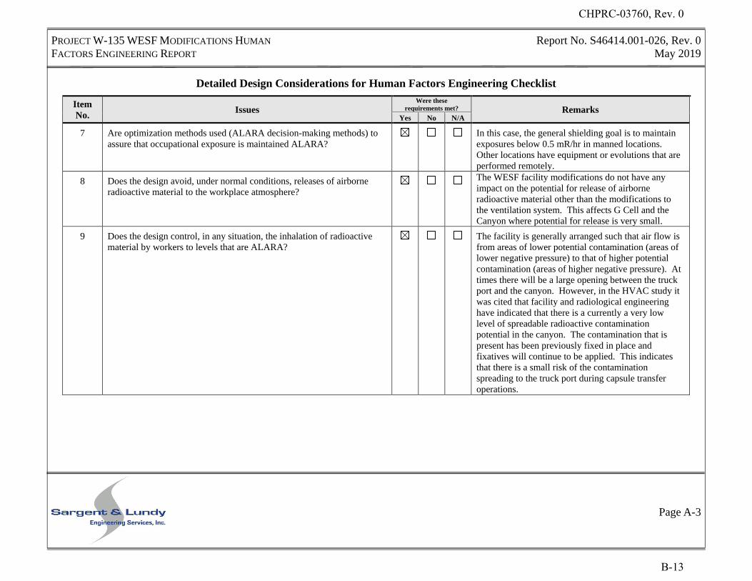
PROJECT W-135 WESF MODIFICATIONS HUMAN
FACTORS ENGINEERING REPORT
Report No. S46414.001-026, Rev. 0
May 2019
Page A-3
Detailed Design Considerations for Human Factors Engineering Checklist
Item
No. Issues
Were these
requirements met? Remarks Yes No N/A
7 Are optimization methods used (ALARA decision-making methods) to
assure that occupational exposure is maintained ALARA?
In this case, the general shielding goal is to maintain
exposures below 0.5 mR/hr in manned locations.
Other locations have equipment or evolutions that are
performed remotely.
8 Does the design avoid, under normal conditions, releases of airborne
radioactive material to the workplace atmosphere?
The WESF facility modifications do not have any
impact on the potential for release of airborne
radioactive material other than the modifications to
the ventilation system. This affects G Cell and the
Canyon where potential for release is very small.
9 Does the design control, in any situation, the inhalation of radioactive
material by workers to levels that are ALARA?
The facility is generally arranged such that air flow is
from areas of lower potential contamination (areas of
lower negative pressure) to that of higher potential
contamination (areas of higher negative pressure). At
times there will be a large opening between the truck
port and the canyon. However, in the HVAC study it
was cited that facility and radiological engineering
have indicated that there is a currently a very low
level of spreadable radioactive contamination
potential in the canyon. The contamination that is
present has been previously fixed in place and
fixatives will continue to be applied. This indicates
that there is a small risk of the contamination
spreading to the truck port during capsule transfer
operations.
CHPRC-03760, Rev. 0
B-13
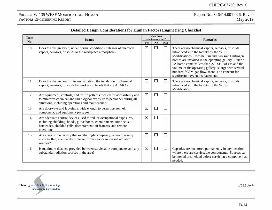
PROJECT W-135 WESF MODIFICATIONS HUMAN
FACTORS ENGINEERING REPORT
Report No. S46414.001-026, Rev. 0
May 2019
Page A-4
Detailed Design Considerations for Human Factors Engineering Checklist
Item
No. Issues
Were these
requirements met? Remarks Yes No N/A
10 Does the design avoid, under normal conditions, releases of chemical
vapors, aerosols, or solids to the workplace atmosphere?
There are no chemical vapors, aerosols, or solids
introduced into the facility by the WESF
Modifications. Two helium and two size 1 nitrogen
bottles are installed in the operating gallery. Since a
1A bottle contains less than 270 SCF of gas and the
volume of the operating gallery is large with several
hundred SCFM gas flow, there is no concern for
significant oxygen displacement.
11 Does the design control, in any situation, the inhalation of chemical
vapors, aerosols, or solids by workers to levels that are ALARA?
There are no chemical vapors, aerosols, or solids
introduced into the facility by the WESF
Modifications.
12 Are equipment, controls, and traffic patterns located for accessibility and
to minimize chemical and radiological exposure to personnel during all
situations, including operations and maintenance?
13 Are doorways and labyrinths wide enough to permit personnel,
component, and equipment passage?
14 Are adequate control devices used to reduce occupational exposures,
including shielding, hoods, glove boxes, containments, interlocks,
barricades, shielded cells, decontamination features, and remote
operations
15 Are areas of the facility that exhibit high occupancy, or are presently
uncontrolled, adequately protected from new or increased radiation
sources?
16 Is maximum distance provided between serviceable components and any
substantial radiation sources in the area?
Capsules are not stored permanently in any location
where there are serviceable components. Sources can
be moved or shielded before servicing a component as
needed.
CHPRC-03760, Rev. 0
B-14
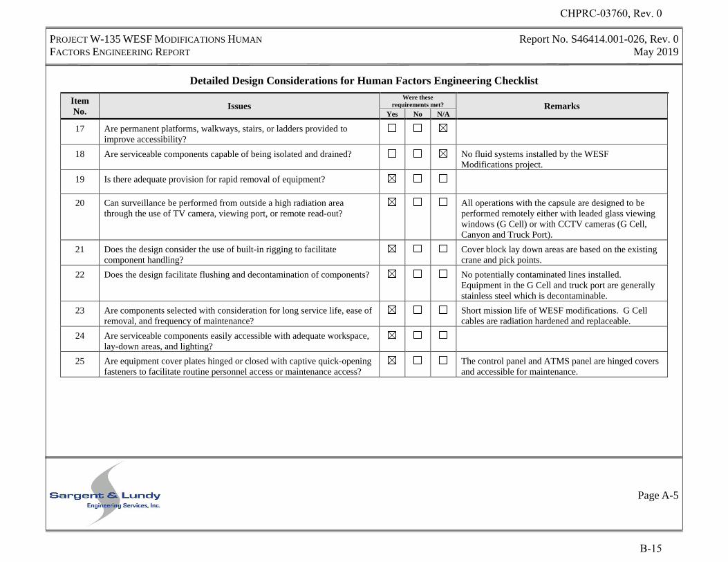
PROJECT W-135 WESF MODIFICATIONS HUMAN
FACTORS ENGINEERING REPORT
Report No. S46414.001-026, Rev. 0
May 2019
Page A-5
Detailed Design Considerations for Human Factors Engineering Checklist
Item
No. Issues
Were these
requirements met? Remarks Yes No N/A
17 Are permanent platforms, walkways, stairs, or ladders provided to
improve accessibility?
18 Are serviceable components capable of being isolated and drained? No fluid systems installed by the WESF
Modifications project.
19 Is there adequate provision for rapid removal of equipment?
20 Can surveillance be performed from outside a high radiation area
through the use of TV camera, viewing port, or remote read-out?
All operations with the capsule are designed to be
performed remotely either with leaded glass viewing
windows (G Cell) or with CCTV cameras (G Cell,
Canyon and Truck Port).
21 Does the design consider the use of built-in rigging to facilitate
component handling?
Cover block lay down areas are based on the existing
crane and pick points.
22 Does the design facilitate flushing and decontamination of components? No potentially contaminated lines installed.
Equipment in the G Cell and truck port are generally
stainless steel which is decontaminable.
23 Are components selected with consideration for long service life, ease of
removal, and frequency of maintenance?
Short mission life of WESF modifications. G Cell
cables are radiation hardened and replaceable.
24 Are serviceable components easily accessible with adequate workspace,
lay-down areas, and lighting?
25 Are equipment cover plates hinged or closed with captive quick-opening
fasteners to facilitate routine personnel access or maintenance access?
The control panel and ATMS panel are hinged covers
and accessible for maintenance.
CHPRC-03760, Rev. 0
B-15
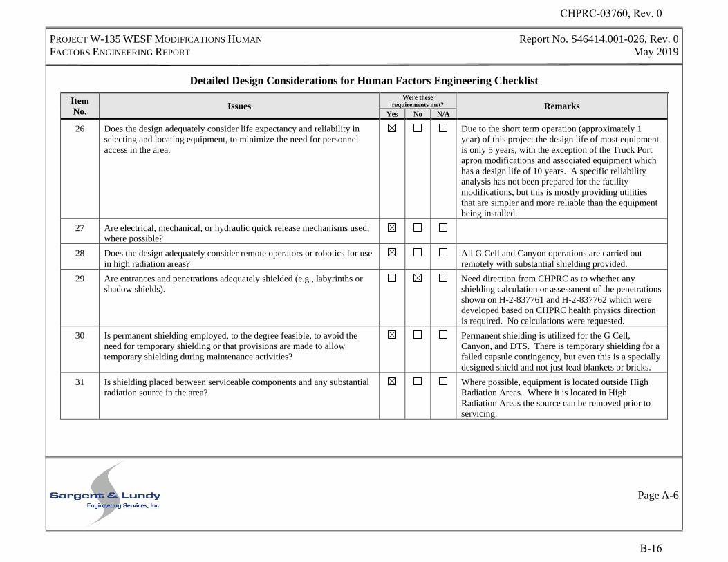
PROJECT W-135 WESF MODIFICATIONS HUMAN
FACTORS ENGINEERING REPORT
Report No. S46414.001-026, Rev. 0
May 2019
Page A-6
Detailed Design Considerations for Human Factors Engineering Checklist
Item
No. Issues
Were these
requirements met? Remarks Yes No N/A
26 Does the design adequately consider life expectancy and reliability in
selecting and locating equipment, to minimize the need for personnel
access in the area.
Due to the short term operation (approximately 1
year) of this project the design life of most equipment
is only 5 years, with the exception of the Truck Port
apron modifications and associated equipment which
has a design life of 10 years. A specific reliability
analysis has not been prepared for the facility
modifications, but this is mostly providing utilities
that are simpler and more reliable than the equipment
being installed.
27 Are electrical, mechanical, or hydraulic quick release mechanisms used,
where possible?
28 Does the design adequately consider remote operators or robotics for use
in high radiation areas?
All G Cell and Canyon operations are carried out
remotely with substantial shielding provided.
29 Are entrances and penetrations adequately shielded (e.g., labyrinths or
shadow shields).
Need direction from CHPRC as to whether any
shielding calculation or assessment of the penetrations
shown on H-2-837761 and H-2-837762 which were
developed based on CHPRC health physics direction
is required. No calculations were requested.
30 Is permanent shielding employed, to the degree feasible, to avoid the
need for temporary shielding or that provisions are made to allow
temporary shielding during maintenance activities?
Permanent shielding is utilized for the G Cell,
Canyon, and DTS. There is temporary shielding for a
failed capsule contingency, but even this is a specially
designed shield and not just lead blankets or bricks.
31 Is shielding placed between serviceable components and any substantial
radiation source in the area?
Where possible, equipment is located outside High
Radiation Areas. Where it is located in High
Radiation Areas the source can be removed prior to
servicing.
CHPRC-03760, Rev. 0
B-16
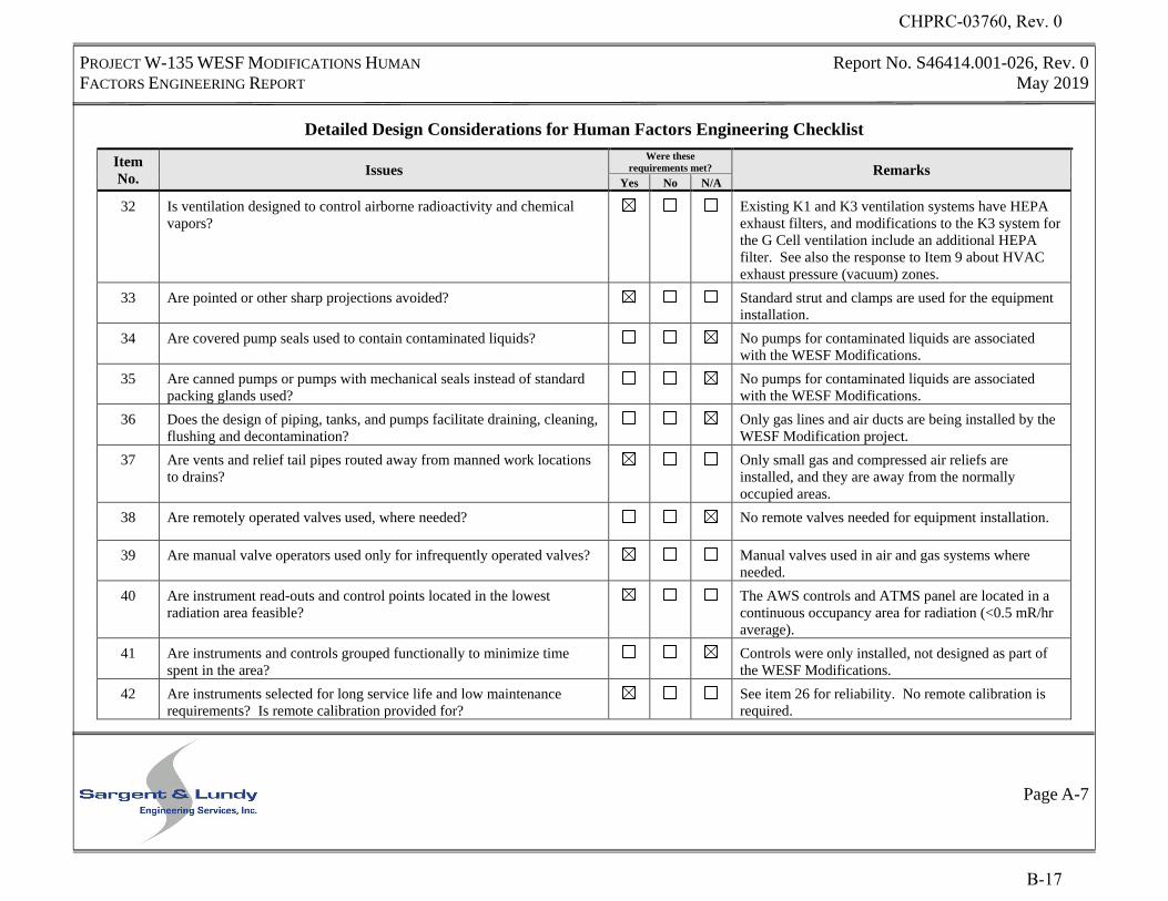
PROJECT W-135 WESF MODIFICATIONS HUMAN
FACTORS ENGINEERING REPORT
Report No. S46414.001-026, Rev. 0
May 2019
Page A-7
Detailed Design Considerations for Human Factors Engineering Checklist
Item
No. Issues
Were these
requirements met? Remarks Yes No N/A
32 Is ventilation designed to control airborne radioactivity and chemical
vapors?
Existing K1 and K3 ventilation systems have HEPA
exhaust filters, and modifications to the K3 system for
the G Cell ventilation include an additional HEPA
filter. See also the response to Item 9 about HVAC
exhaust pressure (vacuum) zones.
33 Are pointed or other sharp projections avoided? Standard strut and clamps are used for the equipment
installation.
34 Are covered pump seals used to contain contaminated liquids? No pumps for contaminated liquids are associated
with the WESF Modifications.
35 Are canned pumps or pumps with mechanical seals instead of standard
packing glands used?
No pumps for contaminated liquids are associated
with the WESF Modifications.
36 Does the design of piping, tanks, and pumps facilitate draining, cleaning,
flushing and decontamination?
Only gas lines and air ducts are being installed by the
WESF Modification project.
37 Are vents and relief tail pipes routed away from manned work locations
to drains?
Only small gas and compressed air reliefs are
installed, and they are away from the normally
occupied areas.
38 Are remotely operated valves used, where needed? No remote valves needed for equipment installation.
39 Are manual valve operators used only for infrequently operated valves? Manual valves used in air and gas systems where
needed.
40 Are instrument read-outs and control points located in the lowest
radiation area feasible?
The AWS controls and ATMS panel are located in a
continuous occupancy area for radiation (<0.5 mR/hr
average).
41 Are instruments and controls grouped functionally to minimize time
spent in the area?
Controls were only installed, not designed as part of
the WESF Modifications.
42 Are instruments selected for long service life and low maintenance
requirements? Is remote calibration provided for?
See item 26 for reliability. No remote calibration is
required.
CHPRC-03760, Rev. 0
B-17
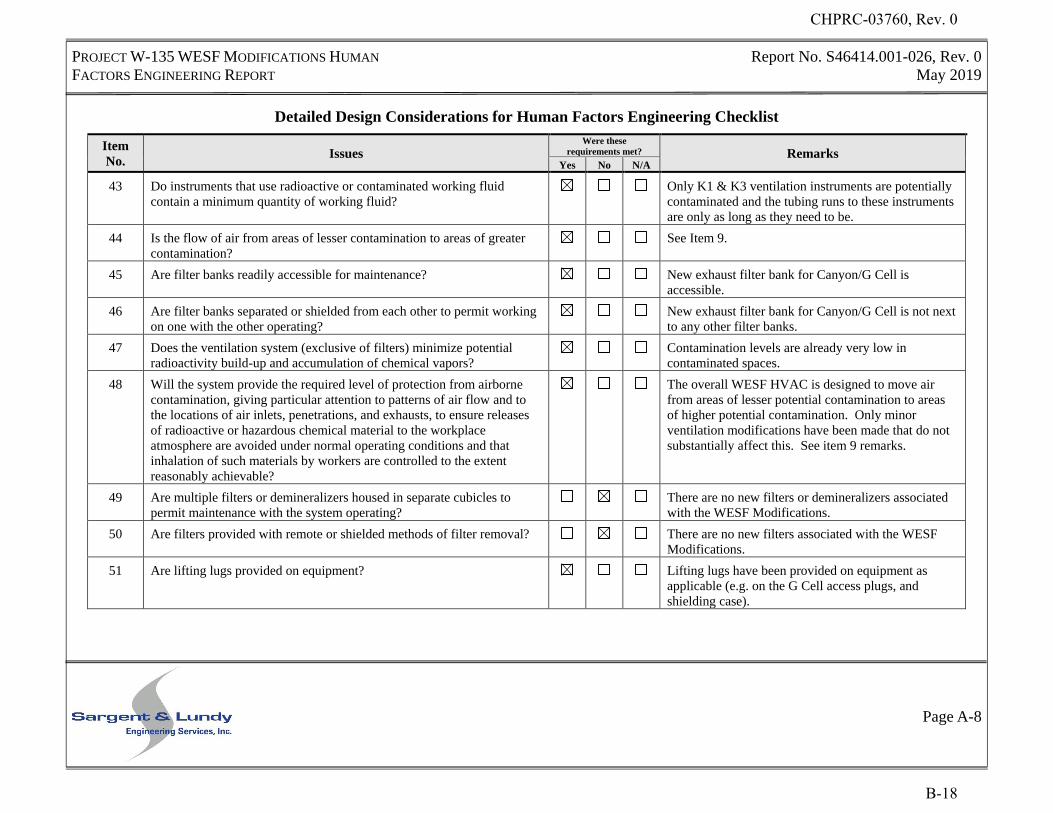
PROJECT W-135 WESF MODIFICATIONS HUMAN
FACTORS ENGINEERING REPORT
Report No. S46414.001-026, Rev. 0
May 2019
Page A-8
Detailed Design Considerations for Human Factors Engineering Checklist
Item
No. Issues
Were these
requirements met? Remarks Yes No N/A
43 Do instruments that use radioactive or contaminated working fluid
contain a minimum quantity of working fluid?
Only K1 & K3 ventilation instruments are potentially
contaminated and the tubing runs to these instruments
are only as long as they need to be.
44 Is the flow of air from areas of lesser contamination to areas of greater
contamination?
See Item 9.
45 Are filter banks readily accessible for maintenance? New exhaust filter bank for Canyon/G Cell is
accessible.
46 Are filter banks separated or shielded from each other to permit working
on one with the other operating?
New exhaust filter bank for Canyon/G Cell is not next
to any other filter banks.
47 Does the ventilation system (exclusive of filters) minimize potential
radioactivity build-up and accumulation of chemical vapors?
Contamination levels are already very low in
contaminated spaces.
48 Will the system provide the required level of protection from airborne
contamination, giving particular attention to patterns of air flow and to
the locations of air inlets, penetrations, and exhausts, to ensure releases
of radioactive or hazardous chemical material to the workplace
atmosphere are avoided under normal operating conditions and that
inhalation of such materials by workers are controlled to the extent
reasonably achievable?
The overall WESF HVAC is designed to move air
from areas of lesser potential contamination to areas
of higher potential contamination. Only minor
ventilation modifications have been made that do not
substantially affect this. See item 9 remarks.
49 Are multiple filters or demineralizers housed in separate cubicles to
permit maintenance with the system operating?
There are no new filters or demineralizers associated
with the WESF Modifications.
50 Are filters provided with remote or shielded methods of filter removal? There are no new filters associated with the WESF
Modifications.
51 Are lifting lugs provided on equipment? Lifting lugs have been provided on equipment as
applicable (e.g. on the G Cell access plugs, and
shielding case).
CHPRC-03760, Rev. 0
B-18
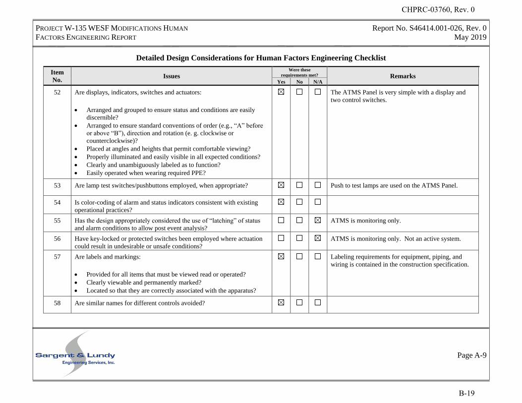
PROJECT W-135 WESF MODIFICATIONS HUMAN
FACTORS ENGINEERING REPORT
Report No. S46414.001-026, Rev. 0
May 2019
Page A-9
Detailed Design Considerations for Human Factors Engineering Checklist
Item
No. Issues
Were these
requirements met? Remarks Yes No N/A
52 Are displays, indicators, switches and actuators:
Arranged and grouped to ensure status and conditions are easily
discernible?
Arranged to ensure standard conventions of order (e.g., “A” before
or above “B”), direction and rotation (e. g. clockwise or
counterclockwise)?
Placed at angles and heights that permit comfortable viewing?
Properly illuminated and easily visible in all expected conditions?
Clearly and unambiguously labeled as to function?
Easily operated when wearing required PPE?
The ATMS Panel is very simple with a display and
two control switches.
53 Are lamp test switches/pushbuttons employed, when appropriate? Push to test lamps are used on the ATMS Panel.
54 Is color-coding of alarm and status indicators consistent with existing
operational practices?
55 Has the design appropriately considered the use of “latching” of status
and alarm conditions to allow post event analysis?
ATMS is monitoring only.
56 Have key-locked or protected switches been employed where actuation
could result in undesirable or unsafe conditions?
ATMS is monitoring only. Not an active system.
57 Are labels and markings:
Provided for all items that must be viewed read or operated?
Clearly viewable and permanently marked?
Located so that they are correctly associated with the apparatus?
Labeling requirements for equipment, piping, and
wiring is contained in the construction specification.
58 Are similar names for different controls avoided?
CHPRC-03760, Rev. 0
B-19
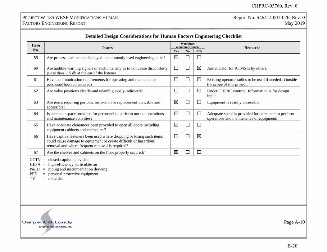
PROJECT W-135 WESF MODIFICATIONS HUMAN
FACTORS ENGINEERING REPORT
Report No. S46414.001-026, Rev. 0
May 2019
Page A-10
Detailed Design Considerations for Human Factors Engineering Checklist
Item
No. Issues
Were these
requirements met? Remarks Yes No N/A
59 Are process parameters displayed in commonly used engineering units?
60 Are audible warning signals of such intensity as to not cause discomfort?
(Less than 115 db at the ear of the listener.)
Annunciator for ATMS is by others.
61 Have communication requirements for operating and maintenance
personnel been considered?
Existing operator radios to be used if needed. Outside
the scope of this project.
62 Are valve positions clearly and unambiguously indicated? Under CHPRC control. Information is for design
input.
63 Are items requiring periodic inspection or replacement viewable and
accessible?
Equipment is readily accessible.
64 Is adequate space provided for personnel to perform normal operations
and maintenance activities?
Adequate space is provided for personnel to perform
operations and maintenance of equipment.
65 Have adequate clearances been provided to open all doors including
equipment cabinets and enclosures?
66 Have captive fasteners been used where dropping or losing such items
could cause damage to equipment or create difficult or hazardous
removal and where frequent removal is required?
67 Are the shelves and cabinets on the floor properly secured?
CCTV = closed-caption television
HEPA = high-efficiency particulate air
P&ID = piping and instrumentation drawing
PPE = personal protective equipment
TV = television
CHPRC-03760, Rev. 0
B-20

CHPRC-03760, Rev. 0
C-1
APPENDIX C
DESIGN INPUT MATRIX
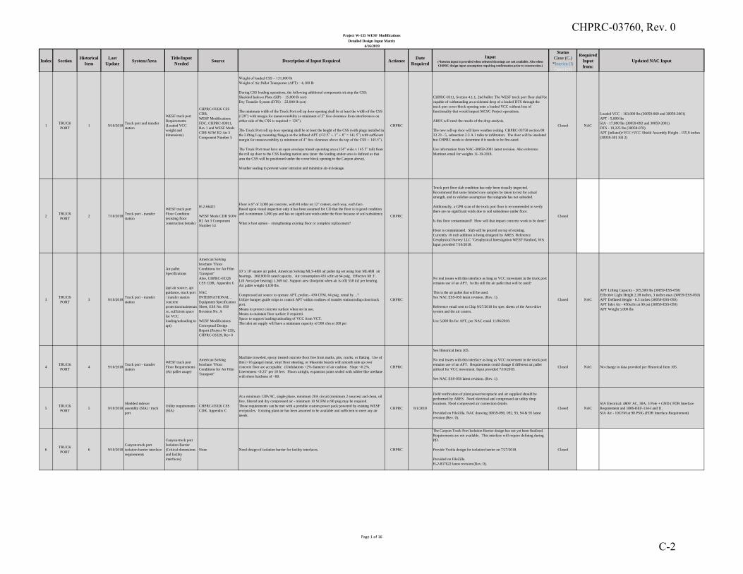
Index SectionHistorical
Item
Last
UpdateSystem/Area
Title/Input
NeededSource Description of Input Required Actionee
Date
Required
Input(*Interim input is provided when released drawings are not available. Also when
CHPRC design input assumption requiring confirmation prior to construction.)
Status
Close (C.)
*Interim (I)
Open (O)
Required
Input
from:
Updated NAC Input
1TRUCK
PORT1 9/10/2018
Truck port and transfer
station
WESF truck port
Requirements
(Loaded VCC
weight and
dimensions)
CHPRC-03326 CSS
CDR,
WESF Modifications
FDC, CHPRC-03011,
Rev 1 and WESF Mods
CDR SOW R2 Att 3
Component Number 5
Weight of loaded CSS – 151,000 lb
Weight of Air Pallet Transporter (APT) – 4,100 lb
During CSS loading operations, the following additional components sit atop the CSS:
Shielded Indexer Plate (SIP) – 15,000 lb (est)
Dry Transfer System (DTS) – 22,000 lb (est)
The minimum width of the Truck Port roll up door opening shall be at least the width of the CSS
(120”) with margin for maneuverability (a minimum of 2” free clearance from interferences on
either side of the CSS is required = 124”).
The Truck Port roll up door opening shall be at least the height of the CSS (with plugs installed in
the Lifting Lug mounting flange) on the inflated APT (132.5” + 1” + 8” = 141.5”) with sufficient
margin for maneuverability (a minimum of 4” free clearance above the top of the CSS = 145.5”).
The Truck Port must have an open envelope transit operating area (124” wide x 145.5” tall) from
the roll up door to the CSS loading station area (note: the loading station area is defined as that
area the CSS will be positioned under the cover block opening to the Canyon above).
Weather sealing to prevent water intrusion and minimize air-in leakage.
CHPRC
CHPRC-0311, Section 4.1.1, 2nd bullet: The WESF truck port floor shall be
capable of withstanding an accidental drop of a loaded DTS through the
truck port cover block opening onto a loaded VCC without loss of
functionality that would impact MCSC Project operations.
ARES will need the results of the drop analysis.
The new roll-up door will have weather sealing. CHPRC-03758 section 08
33 23 - 5, subsection 2.3 A.1 talks to infiltration. The door will be insulated
but CHPRC needs to determine if it needs to be fire-rated.
Use information from NAC-30059-2001 latest revision. Also reference
Martinez email for weights 11-19-2018.
Closed NAC
Loaded VCC - 163,000 lbs (30059-060 and 30059-2001)
APT - 5,000 lbs
SIA - 17,000 lbs (30059-092 and 30059-2001)
DTS - 19,225 lbs (30059-070)
APT (inflated)+VCC+VCC Shield Assembly Height - 155.9 inches
(30059-301 SH 2)
2TRUCK
PORT2 7/10/2018
Truck port - transfer
station
WESF truck port
Floor Condition
(existing floor
construction details)
H-2-66421
WESF Mods CDR SOW
R2 Att 3 Component
Number 14
Floor is 8" of 3,000 psi concrete, with #4 rebar on 12" centers, each way, each face.
Based upon visual inspection only it has been assumed for CD that the floor is in good condition
and is minimum 3,000 psi and has no significant voids under the floor because of soil subsidence.
What is best option – strengthening existing floor or complete replacement?
CHPRC
Truck port floor slab condition has only been visually inspected.
Recommend that some limited core samples be taken to test for actual
strength, and to validate assumption that subgrade has not subsided.
Additionally, a GPR scan of the truck port floor is recommended to verify
there are no significant voids due to soil subsidence under floor.
Is this floor contaminated? How will that impact concrete work to be done?
Floor is contaminated. Slab will be poured on top of existing.
Currently 10 inch addition is being designed by ARES. Reference
Geophysical Survey LLC "Geophysical Investigation WESF Hanford, WA
Input provided 7/10/2018.
Closed
3TRUCK
PORT3 9/10/2018
Truck port - transfer
station
Air pallet
Specifications
(apt air source, apt
guidance, truck port
/ transfer station
concrete
protection/maintenan
ce, sufficient space
for VCC
loading/unloading to
apt)
American Solving
brochure "Floor
Conditions for Air Film
Transport"
Also, CHPRC-03326
CSS CDR, Appendix C
NAC
INTERNATIONAL ,
Equipment Specification
Sheet, ESS No. 050
Revision No. A
WESF Modifications
Conceptual Design
Report (Project W-135),
CHPRC-03329, Rev 0
10' x 10' square air pallet, American Solving MLS-48H air pallet rig set using four ML48H air
bearings. 360,000 lb rated capacity. Air consumption 435 scfm at 64 psig. Effective lift 3".
Lift Area (per bearing) 1,369 in2. Support area (footprint when air is off) 558 in2 per bearing.
Air pallet weight 4,100 lbs.
Compressed air source to operate APT, prelim.- 450 CFM, 64 psig, rental by…?
Utilize bumper guide strips to control APT within confines of transfer station/rollup door/truck
port.
Means to protect concrete surface when not in use.
Means to maintain floor surface if required.
Space to support loading/unloading of VCC from VCT.
The inlet air supply will have a minimum capacity of 580 cfm at 100 psi
CHPRC
No real issues with this interface as long as VCC movement in the truck port
remains use of an APT. Is this still the air pallet that will be used?
This is the air pallet that will be used.
See NAC ESS-050 latest revision. (Rev. 1).
Reference email sent to Chip 9/27/2018 for spec sheets of the Aero-drive
system and the air casters.
Use 5,000 lbs for APT, per NAC email 11/06/2018.
Closed NAC
APT Lifting Capacity - 205,500 lbs (30059-ESS-050)
Effective Light Height 2.38 inches, 3 inches max (30059-ESS-050)
APT Deflated Height - 6.5 inches (30059-ESS-050)
APT Inlet Air - 450scfm at 90 psi (30059-ESS-050)
APT Weight 5,000 lbs
4TRUCK
PORT4 9/10/2018
Truck port - transfer
station
WESF truck port
Floor Requirements
(Air pallet usage)
American Solving
brochure "Floor
Conditions for Air Film
Transport"
Machine troweled, epoxy treated concrete floor free from marks, pits, cracks, or flaking. Use of
thin (<16 gauge) metal, vinyl floor sheeting, or Masonite boards with smooth side up over
concrete floor are acceptable. (Undulations <2% diameter of air cushion. Slope <0.2%.
Unevenness <0.25" per 10 feet. Floors airtight, expansion joints sealed with rubber-like urethane
with shore hardness of ~80.
CHPRC
See Historical Item 105.
No real issues with this interface as long as VCC movement in the truck port
remains use of an APT. Requirements could change if different air pallet
utilized for VCC movement. Input provided 7/10/2018.
See NAC ESS-050 latest revision. (Rev. 1).
Closed NAC No change to data provided per Historical Item 105.
5TRUCK
PORT5 9/10/2018
Shielded indexer
assembly (SIA) / truck
port
Utility requirements
(SIA)
CHPRC-03326 CSS
CDR, Appendix C
At a minimum 120VAC, single phase, minimum 20A circuit (minimum 2 sources) and clean, oil
free, filtered and dry compressed air - minimum 10 SCFM at 90 psig may be required.
These requirements can be met with a portable custom power pack powered by existing WESF
receptacles. Existing plant air has been assumed to be available and sufficient to meet any air
needs.
CHPRC 8/1/2018
Field verification of plant power/receptacle and air supplied should be
performed by ARES. Need electrical and compressed air utility drop
locations. Need compressed air connection details.
Provided on FileZilla. NAC drawing 30059-090, 092, 93, 94 & 95 latest
revision (Rev. 0).
Closed NAC
SIA Electrical: 480V AC, 30A, 3 Pole + GND ( FDR Interface
Requirement and 1806-HEF-134-I and I1.
SIA Air - 10CFM at 90 PSIG (FDR Interface Requirement)
6TRUCK
PORT6 9/10/2018
Canyon-truck port
isolation barrier interface
requirements
Canyon-truck port
Isolation Barrier
(Critical dimensions
and facility
interfaces)
None Need design of isolation barrier for facility interfaces. CHPRC
The Canyon-Truck Port Isolation Barrier design has not yet been finalized.
Requirements are not available. This interface will require defining during
PD.
Provide Veolia design for isolation barrier on 7/27/2018.
Provided on FileZilla.
H-2-837622 latest revision (Rev. 0).
Closed
Project W-135 WESF Modifications
Detailed Design Input Matrix
4/16/2019
Page 1 of 16
CHPRC-03760, Rev. 0
C-2
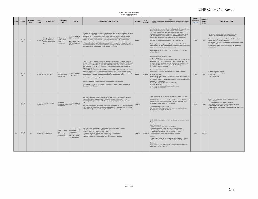
Index SectionHistorical
Item
Last
UpdateSystem/Area
Title/Input
NeededSource Description of Input Required Actionee
Date
Required
Input(*Interim input is provided when released drawings are not available. Also when
CHPRC design input assumption requiring confirmation prior to construction.)
Status
Close (C.)
*Interim (I)
Open (O)
Required
Input
from:
Updated NAC Input
Project W-135 WESF Modifications
Detailed Design Input Matrix
4/16/2019
7TRUCK
PORT7 9/10/2018
Transportable storage
canister (TSC) He
backfill system / truck
port
TSC evacuation/He
Backfill System
(Utility
requirements)
CHPRC-03326 CSS
CDR, Appendix C
WESF Mods CDR SOW
R2 Att 3 Component
Number 8
Backfill of the TSC cavities will be performed with Ultra-High Purity (UHP) Helium. The typical
industry process UHP Helium is procured and staged using compressed gas cylinders and
dispensed to the CSS through use of a combination of regulator, gauges, tubing and fittings.
Multiple compressed gas cylinders may be deployed via a manifold system to minimize the
potential for process disruption due to a depletion of the available UHP Helium inventory.
NAC has indicated in their CDR that a custom electrical “power pack” providing 480 volt, 3
phase, 60 hertz, 50 amp power via a NEMA approved receptacle should be a sufficient source for
the Evacuation and Helium Backfill (EHBS) vacuum pump motor.
CHPRC
Avoiding a process disruption due to a depleted gas bottle requires the need
for an automatic change over system. This will be incorporated.
The recent project decision to no longer require welding of the UCS’s and
instead use mechanical closure of the UCS’s and a welded closure of the
TSC will additionally require an Ultrasonic Weld Testing System and
Helium Mass Spectrometer Leak Detector at the TSC weld location.
NAC has not yet engineered this change. This will occur in PD.
Utility requirements to support this changed operations will need to be
revisited during PD. NAC equipment utility connection details and locations
inside the Truck Port will also need to be defined.
Provided on FileZilla on 9/9/2018. NAC 30059-80, 81, 310 &313 latest
revision (Rev. 0).
Closed NAC
The Truckport Control Panel requires a 480V AC, 30A,
3 Pole + GND source. (FDR Interface Requirements).
The vacuum pump motor (preferably located in the Manipulator
Rebuild Shop) will require a 3 Pole 240-
265/415-460 V ±5 %, 60 Hz power source with a minimum current
rating of 10A. This item also stands
alone from the Control Panel referenced above. (FDR Interface
Requirements).
8TRUCK
PORT8 9/10/2018 Truck port / HVAC
Truck port
temporary cooling
system (TCS)
CHPRC-03326 CSS
CDR, Appendix C
During CSS loading activities, capsule heat load contained within the UCS will be transferred
from the G-Cell to the Truck Port as the UCSs are loaded into the TSC. Up to 33kW of heat will
have to be removed from the CSS while it is located in the Truck Port. For the maximum heat
load rejection from the CSS while in the Truck Port, a minimum airflow of 500 scfm at 76
degrees F is required.
During CD it was estimated that the Truck Port cooling and the EHBS combined would require
approx. 49 amps at 480 VAC. During CD an existing 480 VAC welding receptacle on a 100
amp circuit. This was determined to be an adequate power source to feed a power cart feeding a
portable chiller. Truck Port temperature to be maintained at a maximum of 80°F.
Heat must be rejected by portable chiller.
What is the additional heat load from NAC welding activities in the truck port?
Need to know where all the heat loads are coming from. Once this is known values must be
documented with references.
CHPRC 9/20/2018
Reference Rutherford email 10/31/2018:
3. WESF Truck Port
a. NAC has performed calculation 30059-3001 Rev 2, MCSC VCC Thermal
Evaluations. NAC calc 3001 determined a peak wattage of 24.8 kw for
strontium capsules loaded in a VCC. To bound the heat load for the truck
port, the entire VCC heat load will be used. The heat design inputs for
WESF Truck port are given below:
b. Ambient temperature limit:
i. 80F; Basis; NAC 30059-3001, MCSC VCC Thermal Evaluations
c. Design Heat Loads
i. Summer heat load – Current WESF ventilation system accommodates for a
summer heat load.
ii. Truck port lighting – Current WESF ventilation system accommodates for
truck port lighting heat load.
iii. CSS Heat load - 24,800 watts, Ref 30059-3001.
iv. Total: 24,800 watts.
v. Provide a 10% contingency for undefined heat loads.
vi. Design Total: 27,280 watts.
Closed NAC
c.i Removed summer heat load
c.ii. Removed truck port lighting
iv. New total.
vi. New Design total
9TRUCK
PORT9 9/10/2018
Truck port - transfer
station
Concrete pad
(Loading and surface
requirements)
CHPRC-03326 CSS
CDR, Appendix C, F
The Transfer Station surface shall be a smooth, flat, level structural surface free of expansion
joints or other surface irregularities that would inhibit or otherwise limit the APT from
maintaining the design air cushion under the CSS necessary to support and move the loaded
CSS.
The Transfer Station shall be capable of withstanding the weight of the VCT carrying the loaded
CSS (231,000 lbs.) and also the loaded CSS being maneuvered by the APT (CS S[151,000 lbs.]
+ APT [4,100 lbs.]) under the VCT during loaded CSS transfer station operations.
CHPRC
These requirements are not expected to significantly change at this point.
CHPRC-0311, Section 4.1.1, last bullet: Modifications to the WESF transfer
station shall meet the same requirements as the truck port floor. ARES
assumes this does not include DTS impact load.
This is simply a design requirement.
Use information from NAC-30059-2001 latest revision. Also reference
Martinez email for weights 11-19-2018.
Closed NAC
Loaded VCC - 163,000 lbs (30059-060 and 30059-2001)
APT - 5,000 lbs
VCC Shield Assembly - 10,900 lbs (30059-154)
TUG: 60,000 lb (Tug Technologies Corporation Operation,
Maintenance & Parts Manual, pg 43 of 1705).
VCT weight with loaded cask: 270,000 lbs (CHBWV Vertical Cask
Transporter)
10TRUCK
PORT10 9/10/2018 Transfer Station
CSS/VCT Lifting
lugs
(Removal and
installation on VCC)
MPC-Capsule Storage
System (MPC_CSS)
Operations and
Maintenance Manual,
30059-P-01, Rev B,
NAC International
1. Provide CHPRC input on WESF Mods design requirements (if any) to support:
- Worker access to install/remove VCC lift lug bolts.
- Lifting/lowering VCC lifting lugs (2 @ 270 lbs.)
- Storage of lifting lugs and bolts - and protection bolts if elected to use.
- Storage of tools to install/torque/remove lift lug bolts
- Space in transfer station area to support installation/removal of lifting lugs.
CHPRC 12/13/2018
1. No ARES design required to support these items. See explanatory notes
below.
Notes / Assumptions:
- Worker access will be by mobile lift or platform.
- Lifting/lowering lugs will be by mobile crane or equivalent.
- Storage of lugs/bolts/tools to be in dedicated VCT work truck.
- Above lift, platform, crane, truck, etc. provided by others.
- 60' x 30' Transfer Station pad expected to be sufficient.
Actions:
- CHPRC will confirm during WESF Mods final design review process.
- Lift Systems Inc. to design spreader bar modification for the VCT.
Reference:
NAC 30059-063 (Rev. 1), Equipment, Tooling and Instrumentation List
(NAC) and 30059-S-01 (Rev. 3).
Closed CHPRC
Page 2 of 16
CHPRC-03760, Rev. 0
C-3
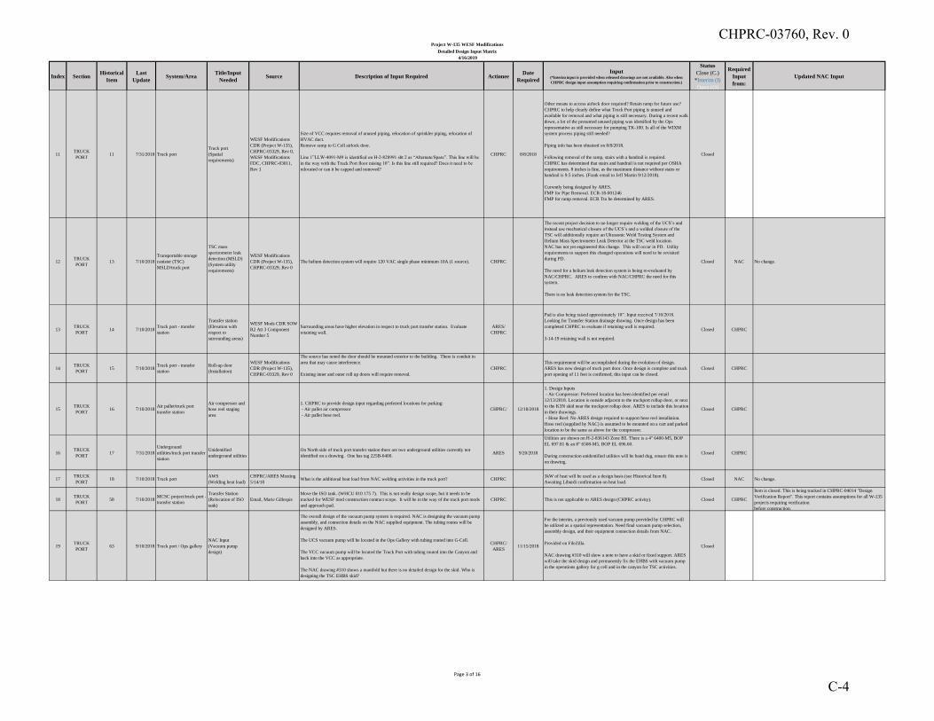
Index SectionHistorical
Item
Last
UpdateSystem/Area
Title/Input
NeededSource Description of Input Required Actionee
Date
Required
Input(*Interim input is provided when released drawings are not available. Also when
CHPRC design input assumption requiring confirmation prior to construction.)
Status
Close (C.)
*Interim (I)
Open (O)
Required
Input
from:
Updated NAC Input
Project W-135 WESF Modifications
Detailed Design Input Matrix
4/16/2019
11TRUCK
PORT11 7/31/2018 Truck port
Truck port
(Spatial
requirements)
WESF Modifications
CDR (Project W-135),
CHPRC-03329, Rev 0,
WESF Modifications
FDC, CHPRC-03011,
Rev 1
Size of VCC requires removal of unused piping, relocation of sprinkler piping, relocation of
HVAC duct.
Remove ramp to G Cell airlock door.
Line 1”LLW-4091-M9 is identified on H-2-828991 sht 2 as “Alternate/Spare”. This line will be
in the way with the Truck Port floor raising 10”. Is this line still required? Does it need to be
relocated or can it be capped and removed?
CHPRC 8/8/2018
Other means to access airlock door required? Retain ramp for future use?
CHPRC to help clearly define what Truck Port piping is unused and
available for removal and what piping is still necessary. During a recent walk
down, a lot of the presumed unused piping was identified by the Ops
representative as still necessary for pumping TK-100. Is all of the WIXM
system process piping still needed?
Piping info has been obtained on 8/8/2018.
Following removal of the ramp, stairs with a handrail is required.
CHPRC has determined that stairs and handrail is not required per OSHA
requirements. 8 inches is fine, as the maximum distance without stairs or
handrail is 9.5 inches. (Frank email to Jeff Martin 9/12/2018).
Currently being designed by ARES.
FMP for Pipe Removal. ECR-18-001246
FMP for ramp removal. ECR Tto be determined by ARES.
Closed
12TRUCK
PORT13 7/10/2018
Transportable storage
canister (TSC)
MSLD/truck port
TSC mass
spectrometer leak
detection (MSLD)
(System utility
requirements)
WESF Modifications
CDR (Project W-135),
CHPRC-03329, Rev 0
The helium detection system will require 120 VAC single phase minimum 10A (1 source). CHPRC
The recent project decision to no longer require welding of the UCS’s and
instead use mechanical closure of the UCS’s and a welded closure of the
TSC will additionally require an Ultrasonic Weld Testing System and
Helium Mass Spectrometer Leak Detector at the TSC weld location.
NAC has not yet engineered this change. This will occur in PD. Utility
requirements to support this changed operations will need to be revisited
during PD.
The need for a helium leak detection system is being re-evaluated by
NAC/CHPRC. ARES to confirm with NAC/CHPRC the need for this
system.
There is no leak detection system for the TSC.
Closed NAC No change.
13TRUCK
PORT14 7/10/2018
Truck port - transfer
station
Transfer station
(Elevation with
respect to
surrounding areas)
WESF Mods CDR SOW
R2 Att 3 Component
Number 5
Surrounding areas have higher elevation in respect to truck port transfer station. Evaluate
retaining wall.
ARES/
CHPRC
Pad is also being raised approximately 10”. Input received 7/10/2018.
Looking for Transfer Station drainage drawing. Once design has been
completed CHPRC to evaluate if retaining wall is required.
3-14-19 retaining wall is not required.
Closed CHPRC
14TRUCK
PORT15 7/10/2018
Truck port - transfer
station
Roll-up door
(Installation)
WESF Modifications
CDR (Project W-135),
CHPRC-03329, Rev 0
The source has noted the door should be mounted exterior to the building. There is conduit in
area that may cause interference.
Existing inner and outer roll up doors will require removal.
CHPRC
This requirement will be accomplished during the evolution of design.
ARES has new design of truck port door. Once design is complete and truck
port opening of 11 feet is confirmed, this input can be closed.
Closed CHPRC
15TRUCK
PORT16 7/10/2018
Air pallet/truck port
transfer station
Air compressor and
hose reel staging
area
1. CHPRC to provide design input regarding preferred locations for parking:
- Air pallet air compressor
- Air pallet hose reel.
CHPRC/ 12/18/2018
1. Design Inputs
- Air Compressor: Preferred location has been identified per email
12/13/2018. Location is outside adjacent to the truckport rollup door, or next
to the K3N skid near the truckport rollup door. ARES to include this location
in their drawings.
- Hose Reel: No ARES design required to support hose reel installation.
Hose reel (supplied by NAC) is assumed to be mounted on a cart and parked
location to be the same as above for the compressor.
Closed CHPRC
16TRUCK
PORT17 7/31/2018
Underground
utilities/truck port transfer
station
Unidentified
underground utilities
On North side of truck port transfer station there are two underground utilities currently not
identified on a drawing. One has tag 225B-6400.ARES 9/20/2018
Utilities are shown on H-2-836143 Zone B5. There is a 4" 6400-M5, BOP
EL 697.81 & an 8" 6508-M5, BOP EL 696.60.
During construction unidentified utilities will be hand dug, ensure this note is
on drawing.
Closed CHPRC
17TRUCK
PORT18 7/10/2018 Truck port
AWS
(Welding heat load)
CHPRC/ARES Meeting
5/14/18What is the additional heat load from NAC welding activities in the truck port? CHPRC
3kW of heat will be used as a design basis (see Historical Item 8).
Awaiting Liburdi confirmation on heat load.Closed NAC No change.
18TRUCK
PORT58 7/10/2018
MCSC project/truck port -
transfer station
Transfer Station
(Relocation of ISO
tank)
Email, Marie Gillespie
Move the ISO tank. (WHCU 010 175 7). This is not really design scope, but it needs to be
tracked for WESF mod construction contract scope. It will be in the way of the truck port mods
and approach pad.
CHPRC This is not applicable to ARES design (CHPRC activity). Closed CHPRC
Item is closed. This is being tracked in CHPRC-04014 "Design
Verification Report". This report contains assumptions for all W-135
projects requiring verification
before construction.
19TRUCK
PORT63 9/10/2018 Truck port / Ops gallery
NAC Input
(Vacuum pump
design)
The overall design of the vacuum pump system is required. NAC is designing the vacuum pump
assembly, and connection details on the NAC supplied equipment. The tubing routes will be
designed by ARES.
The UCS vacuum pump will be located in the Ops Gallery with tubing routed into G-Cell.
The VCC vacuum pump will be located the Truck Port with tubing routed into the Canyon and
back into the VCC as appropriate.
The NAC drawing #310 shows a manifold but there is no detailed design for the skid. Who is
designing the TSC EHBS skid?
CHPRC/
ARES11/15/2018
For the interim, a previously used vacuum pump provided by CHPRC will
be utilized as a spatial representation. Need final vacuum pump selection,
assembly design, and their equipment connection details from NAC.
Provided on FileZilla.
NAC drawing #310 will show a note to have a skid or fixed support. ARES
will take the skid design and permanently fix the EHBS with vacuum pump
in the operations gallery for g cell and in the canyon for TSC activities.
Closed
Page 3 of 16
CHPRC-03760, Rev. 0
C-4
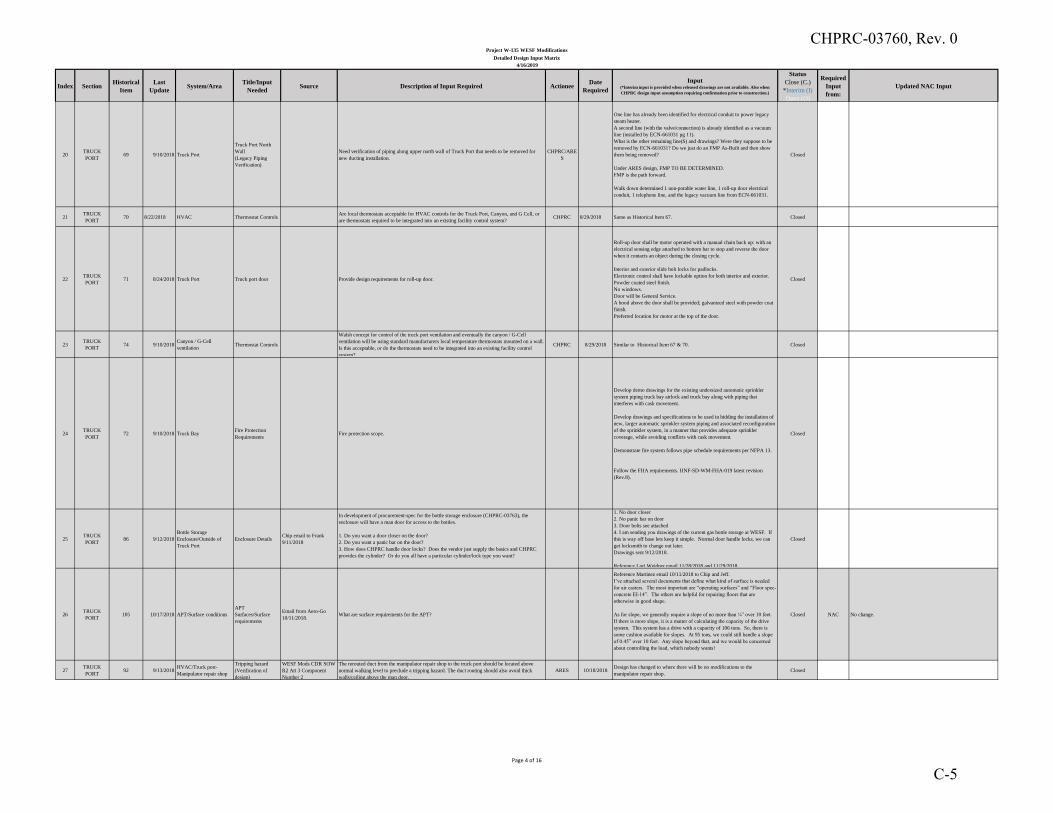
Index SectionHistorical
Item
Last
UpdateSystem/Area
Title/Input
NeededSource Description of Input Required Actionee
Date
Required
Input(*Interim input is provided when released drawings are not available. Also when
CHPRC design input assumption requiring confirmation prior to construction.)
Status
Close (C.)
*Interim (I)
Open (O)
Required
Input
from:
Updated NAC Input
Project W-135 WESF Modifications
Detailed Design Input Matrix
4/16/2019
20TRUCK
PORT69 9/10/2018 Truck Port
Truck Port North
Wall
(Legacy Piping
Verification)
Need verification of piping along upper north wall of Truck Port that needs to be removed for
new ducting installation.
CHPRC/ARE
S
One line has already been identified for electrical conduit to power legacy
steam heater.
A second line (with the valve/connection) is already identified as a vacuum
line (installed by ECN-661031 pg 11).
What is the other remaining line(S) and drawings? Were they suppose to be
removed by ECN-661031? Do we just do an FMP As-Built and then show
them being removed?
Under ARES design, FMP TO BE DETERMINED.
FMP is the path forward.
Walk down determined 1 non-potable water line, 1 roll-up door electrical
conduit, 1 telephone line, and the legacy vacuum line from ECN-661031.
Closed
21TRUCK
PORT70 8/22/2018 HVAC Thermostat Controls
Are local thermostats acceptable for HVAC controls for the Truck Port, Canyon, and G Cell, or
are thermostats required to be integrated into an existing facility control system?CHPRC 8/29/2018 Same as Historical Item 67. Closed
22TRUCK
PORT71 8/24/2018 Truck Port Truck port door Provide design requirements for roll-up door.
Roll-up door shall be motor operated with a manual chain back up: with an
electrical sensing edge attached to bottom bar to stop and reverse the door
when it contacts an object during the closing cycle.
Interior and exterior slide bolt locks for padlocks.
Electronic control shall have lockable option for both interior and exterior.
Powder coated steel finish.
No windows.
Door will be General Service.
A hood above the door shall be provided; galvanized steel with powder coat
finish.
Preferred location for motor at the top of the door.
Closed
23TRUCK
PORT74 9/10/2018
Canyon / G-Cell
ventilationThermostat Controls
Walsh concept for control of the truck port ventilation and eventually the canyon / G-Cell
ventilation will be using standard manufacturers local temperature thermostats mounted on a wall.
Is this acceptable, or do the thermostats need to be integrated into an existing facility control
system?
CHPRC 8/29/2018 Similar to Historical Item 67 & 70. Closed
24TRUCK
PORT72 9/10/2018 Truck Bay
Fire Protection
Requirements Fire protection scope.
Develop demo drawings for the existing undersized automatic sprinkler
system piping truck bay airlock and truck bay along with piping that
interferes with cask movement.
Develop drawings and specifications to be used in bidding the installation of
new, larger automatic sprinkler system piping and associated reconfiguration
of the sprinkler system, in a manner that provides adequate sprinkler
coverage, while avoiding conflicts with cask movement.
Demonstrate fire system follows pipe schedule requirements per NFPA 13.
Follow the FHA requirements. HNF-SD-WM-FHA-019 latest revision
(Rev.8).
Closed
25TRUCK
PORT86 9/12/2018
Bottle Storage
Enclosure/Outside of
Truck Port
Enclosure DetailsChip email to Frank
9/11/2018
In development of procurement-spec for the bottle storage enclosure (CHPRC-03763), the
enclosure will have a man door for access to the bottles.
1. Do you want a door closer on the door?
2. Do you want a panic bar on the door?
3. How does CHPRC handle door locks? Does the vendor just supply the basics and CHPRC
provides the cylinder? Or do you all have a particular cylinder/lock type you want?
1. No door closer
2. No panic bar on door
3. Door bolts see attached
4. I am sending you drawings of the current gas bottle storage at WESF. If
this is way off base lets keep it simple. Normal door handle locks, we can
get locksmith to change out later.
Drawings sent 9/12/2018.
Reference Lori Weidner email 11/28/2018 and 11/29/2018.
Closed
26TRUCK
PORT105 10/17/2018 APT/Surface conditions
APT
Surfaces/Surface
requirements
Email from Aero-Go
10/11/2018.What are surface requirements for the APT?
Reference Martinez email 10/11/2018 to Chip and Jeff.
I’ve attached several documents that define what kind of surface is needed
for air casters. The most important are “operating surfaces” and “Floor spec-
concrete EI-14”. The others are helpful for repairing floors that are
otherwise in good shape.
As for slope, we generally require a slope of no more than ¼” over 10 feet.
If there is more slope, it is a matter of calculating the capacity of the drive
system. This system has a drive with a capacity of 106 tons. So, there is
some cushion available for slopes. At 95 tons, we could still handle a slope
of 0.45” over 10 feet. Any slope beyond that, and we would be concerned
about controlling the load, which nobody wants!
Closed NAC No change.
27TRUCK
PORT92 9/13/2018
HVAC/Truck port-
Manipulator repair shop
Tripping hazard
(Verification of
design)
WESF Mods CDR SOW
R2 Att 3 Component
Number 2
The rerouted duct from the manipulator repair shop to the truck port should be located above
normal walking level to preclude a tripping hazard. The duct routing should also avoid thick
walls/ceiling above the man door.
ARES 10/18/2018Design has changed to where there will be no modifications to the
manipulator repair shop.Closed
Page 4 of 16
CHPRC-03760, Rev. 0
C-5
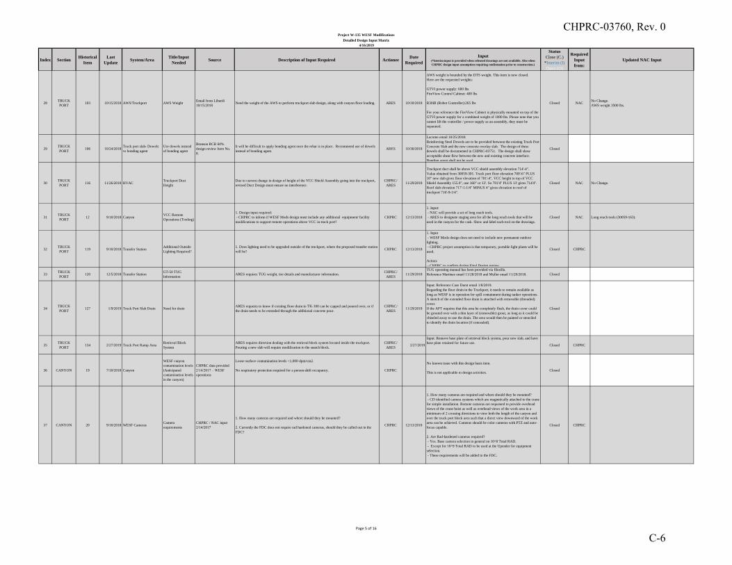
Index SectionHistorical
Item
Last
UpdateSystem/Area
Title/Input
NeededSource Description of Input Required Actionee
Date
Required
Input(*Interim input is provided when released drawings are not available. Also when
CHPRC design input assumption requiring confirmation prior to construction.)
Status
Close (C.)
*Interim (I)
Open (O)
Required
Input
from:
Updated NAC Input
Project W-135 WESF Modifications
Detailed Design Input Matrix
4/16/2019
28TRUCK
PORT103 10/15/2018 AWS/Truckport AWS Weight
Email from Liburdi
10/15/2018Need the weight of the AWS to perform truckport slab design, along with canyon floor loading. ARES 10/18/2018
AWS weight is bounded by the DTS weight. This item is now closed.
Here are the requested weights:
GTVI power supply: 600 lbs
FireView Control Cabinet: 400 lbs
R30iB (Robot Controller):265 lbs
For your reference the FireView Cabinet is physically mounted on top of the
GTVI power supply for a combined weight of 1000 lbs. Please note that you
cannot lift the controller / power supply as an assembly, they must be
separated.
Closed NACNo Change.
AWS weight 3500 lbs.
29TRUCK
PORT106 10/24/2018
Truck port slab- Dowels
vs bonding agent
Use dowels instead
of bonding agent
Branson RCR 60%
design review Item No.
8.
It will be difficult to apply bonding agent once the rebar is in place. Recommend use of dowels
instead of bonding agent.ARES 10/30/2018
Lacome email 10/25/2018:
Reinforcing Steel Dowels are to be provided between the existing Truck Port
Concrete Slab and the new concrete overlay slab. The design of these
dowels shall be documented in CHPRC-03751. The design shall show
acceptable shear flow between the new and existing concrete interface.
Bonding agent shall not be used.
Closed
30TRUCK
PORT116 11/26/2018 HVAC
Truckport Duct
Height
Due to current change in design of height of the VCC Shield Assembly going into the truckport,
revised Duct Design must ensure no interference.
CHPRC/
ARES11/29/2018
Truckport duct shall be above VCC shield assembly elevation 714'-4".
Value obtained from 30059-301. Truck port floor elevation 700'-6" PLUS
10" new slab gives floor elevation of 701'-4", VCC height to top of VCC
Shield Assembly 155.9", use 160" or 13'. So 701'4" PLUS 13' gives 714'4".
Roof slab elevation 717'-1-1/4" MINUS 4" gives elevation to roof of
truckport 716'-9-1/4".
Closed NAC No Change.
31TRUCK
PORT12 9/10/2018 Canyon
VCC Remote
Operations (Tooling)
1. Design input required:
- CHPRC to inform if WESF Mods design must include any additional equipment/ facility
modifications to support remote operations above VCC in truck port?
CHPRC 12/13/2018
1. Input:
- NAC will provide a set of long reach tools.
- ARES to designate staging area for all the long reach tools that will be
used in the canyon for the cask. Show and label each tool on the drawings.
Closed NAC Long reach tools (30059-163).
32TRUCK
PORT119 9/10/2018 Transfer Station
Additional Outside
Lighting Required?
1. Does lighting need to be upgraded outside of the truckport, where the proposed transfer station
will be?CHPRC 12/13/2018
1. Input
- WESF Mods design does not need to include new permanent outdoor
lighting.
- CHPRC project assumption is that temporary, portable light plants will be
used.
Action:
- CHPRC to confirm during Final Design review.
Closed CHPRC
33TRUCK
PORT120 12/5/2018 Transfer Station
GT-50 TUG
Information ARES requires TUG weight, tire details and manufacturer information.
CHPRC/
ARES11/29/2018
TUG operating manual has been provided via filezilla.
Reference Martinez email 11/28/2018 and Muller email 11/29/2018. Closed
34TRUCK
PORT127 1/9/2019 Truck Port Slab Drain Need for drain
ARES requests to know if existing floor drain to TK-100 can be capped and poured over, or if
the drain needs to be extended through the additional concrete pour.
CHPRC/
ARES11/29/2018
Input: Reference Case Durst email 1/8/2019.
Regarding the floor drain in the Truckport, it needs to remain available as
long as WESF is in operation for spill containment during tanker operations.
A sketch of the extended floor drain is attached with removable (threaded)
cover.
If the APT requires that this area be completely flush, the drain cover could
be grouted over with a thin layer of (removable) grout, as long as it could be
chiseled away to use the drain. The area would then be painted or stenciled
to identify the drain location (if concealed).
Closed
35TRUCK
PORT134 2/27/2019 Truck Port Ramp Area
Retrieval Block
System
ARES requires direction dealing with the retrieval block system located inside the truckport.
Pouring a new slab will require modification to the snatch block.
CHPRC/
ARES2/27/2019
Input: Remove base plate of retrieval block system, pour new slab, and have
base plate retained for future use.Closed CHPRC
36 CANYON 19 7/10/2018 Canyon
WESF canyon
contamination levels
(Anticipated
contamination levels
in the canyon)
CHPRC data provided
2/14/2017 – WESF
operations
Loose surface contamination levels <1,000 dpm/cm2.
No respiratory protection required for a person-shift occupancy. CHPRC
No known issue with this design basis item.
This is not applicable to design activities.Closed
37 CANYON 20 9/10/2018 WESF CamerasCamera
requirements
CHPRC / NAC input
2/14/2017
1. How many cameras are required and where should they be mounted?
2. Currently the FDC does not require rad hardened cameras, should they be called out in the
FDC?
CHPRC 12/13/2018
1. How many cameras are required and where should they be mounted?
- CD identified camera systems which are magnetically attached to the crane
for simple installation. Remote cameras are requested to provide overhead
views of the crane hoist as well as overhead views of the work area in a
minimum of 2 crossing directions to view both the length of the canyon and
over the truck port block area such that a direct view downward of the work
area can be achieved. Cameras should be color cameras with PTZ and auto-
focus capable.
2. Are Rad-hardened cameras required?
- Yes. Base camera selection in general on 10^8 Total RAD.
- Except for 10^9 Total RAD to be used at the Upender for equipment
selection.
- These requirements will be added to the FDC.
Closed CHPRC
Page 5 of 16
CHPRC-03760, Rev. 0
C-6
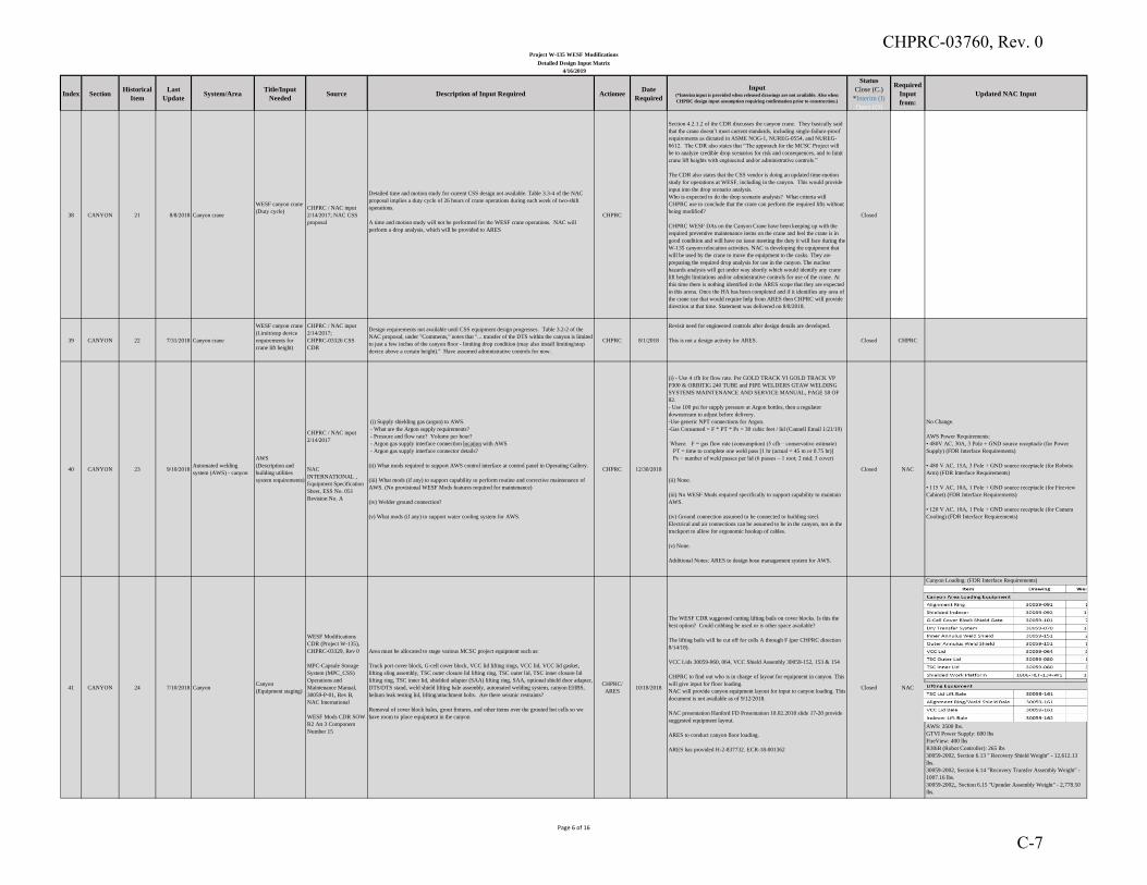
Index SectionHistorical
Item
Last
UpdateSystem/Area
Title/Input
NeededSource Description of Input Required Actionee
Date
Required
Input(*Interim input is provided when released drawings are not available. Also when
CHPRC design input assumption requiring confirmation prior to construction.)
Status
Close (C.)
*Interim (I)
Open (O)
Required
Input
from:
Updated NAC Input
Project W-135 WESF Modifications
Detailed Design Input Matrix
4/16/2019
38 CANYON 21 8/8/2018 Canyon crane
WESF canyon crane
(Duty cycle)CHPRC / NAC input
2/14/2017; NAC CSS
proposal
Detailed time and motion study for current CSS design not available. Table 3.3-4 of the NAC
proposal implies a duty cycle of 26 hours of crane operations during each week of two-shift
operations.
A time and motion study will not be performed for the WESF crane operations. NAC will
perform a drop analysis, which will be provided to ARES
CHPRC
Section 4.2.1.2 of the CDR discusses the canyon crane. They basically said
that the crane doesn’t meet current standards, including single-failure-proof
requirements as dictated in ASME NOG-1, NUREG-0554, and NUREG-
0612. The CDR also states that “The approach for the MCSC Project will
be to analyze credible drop scenarios for risk and consequences, and to limit
crane lift heights with engineered and/or administrative controls.”
The CDR also states that the CSS vendor is doing an updated time-motion
study for operations at WESF, including in the canyon. This would provide
input into the drop scenario analysis.
Who is expected to do the drop scenario analysis? What criteria will
CHPRC use to conclude that the crane can perform the required lifts without
being modified?
CHPRC WESF DAs on the Canyon Crane have been keeping up with the
required preventive maintenance items on the crane and feel the crane is in
good condition and will have no issue meeting the duty it will face during the
W-135 canyon relocation activities. NAC is developing the equipment that
will be used by the crane to move the equipment to the casks. They are
preparing the required drop analysis for use in the canyon. The nuclear
hazards analysis will get under way shortly which would identify any crane
lift height limitations and/or administrative controls for use of the crane. At
this time there is nothing identified in the ARES scope that they are expected
in this arena. Once the HA has been completed and if it identifies any area of
the crane use that would require help from ARES then CHPRC will provide
direction at that time. Statement was delivered on 8/8/2018.
Closed
39 CANYON 22 7/31/2018 Canyon crane
WESF canyon crane
(Limit/stop device
requirements for
crane lift height)
CHPRC / NAC input
2/14/2017;
CHPRC-03326 CSS
CDR
Design requirements not available until CSS equipment design progresses. Table 3.2-2 of the
NAC proposal, under "Comments," notes that "... transfer of the DTS within the canyon is limited
to just a few inches of the canyon floor - limiting drop condition (may also install limiting/stop
device above a certain height)." Have assumed administrative controls for now.
CHPRC 8/1/2018
Revisit need for engineered controls after design details are developed.
This is not a design activity for ARES. Closed CHPRC
40 CANYON 23 9/10/2018Automated welding
system (AWS) - canyon
AWS
(Description and
building utilities
system requirements)
CHPRC / NAC input
2/14/2017
NAC
INTERNATIONAL ,
Equipment Specification
Sheet, ESS No. 051
Revision No. A
(i) Supply shielding gas (argon) to AWS.
- What are the Argon supply requirements?
- Pressure and flow rate? Volume per hour?
- Argon gas supply interface connection location with AWS
- Argon gas supply interface connector details?
(ii) What mods required to support AWS control interface at control panel in Operating Gallery.
(iii) What mods (if any) to support capability to perform routine and corrective maintenance of
AWS. (No provisional WESF Mods features required for maintenance)
(iv) Welder ground connection?
(v) What mods (if any) to support water cooling system for AWS.
CHPRC 12/30/2018
(i) - Use 4 cfh for flow rate. Per GOLD TRACK VI GOLD TRACK VP
P300 & ORBITIG 240 TUBE and PIPE WELDERS GTAW WELDING
SYSTEMS MAINTENANCE AND SERVICE MANUAL, PAGE 58 OF
82.
- Use 100 psi for supply pressure at Argon bottles, then a regulator
downstream to adjust before delivery.
-Use generic NPT connections for Argon.
-Gas Consumed = F * PT * Ps = 30 cubic feet / lid (Cannell Email 1/21/19)
Where: F = gas flow rate (consumption) (5 cfh – conservative estimate)
PT = time to complete one weld pass [1 hr (actual = 45 m or 0.75 hr)]
Ps = number of weld passes per lid (6 passes – 1 root; 2 mid; 3 cover)
(ii) None.
(iii) No WESF Mods required specifically to support capability to maintain
AWS.
(iv) Ground connection assumed to be connected to building steel.
Electrical and air connections can be assumed to be in the canyon, not in the
truckport to allow for ergonomic hookup of cables.
(v) None.
Additional Notes: ARES to design hose management system for AWS.
Closed NAC
No Change.
AWS Power Requirements:
• 480V AC, 30A, 3 Pole + GND source receptacle (for Power
Supply) (FDR Interface Requirements)
• 480 V AC, 15A, 3 Pole + GND source receptacle (for Robotic
Arm) (FDR Interface Requirements)
• 115 V AC, 10A, 1 Pole + GND source receptacle (for Fireview
Cabinet) (FDR Interface Requirements)
• 120 V AC, 10A, 1 Pole + GND source receptacle (for Camera
Cooling) (FDR Interface Requirements)
41 CANYON 24 7/10/2018 CanyonCanyon
(Equipment staging)
WESF Modifications
CDR (Project W-135),
CHPRC-03329, Rev 0
MPC-Capsule Storage
System (MPC_CSS)
Operations and
Maintenance Manual,
30059-P-01, Rev B,
NAC International
WESF Mods CDR SOW
R2 Att 3 Component
Number 15
Area must be allocated to stage various MCSC project equipment such as:
Truck port cover block, G-cell cover block, VCC lid lifting rings, VCC lid, VCC lid gasket,
lifting sling assembly, TSC outer closure lid lifting ring, TSC outer lid, TSC inner closure lid
lifting ring, TSC inner lid, shielded adapter (SAA) lifting ring, SAA, optional shield door adapter,
DTS/DTS stand, weld shield lifting bale assembly, automated welding system, canyon EHBS,
helium leak testing lid, lifting/attachment bolts. Are there seismic restraints?
Removal of cover block bales, grout fixtures, and other items over the grouted hot cells so we
have room to place equipment in the canyon
CHPRC/
ARES10/18/2018
The WESF CDR suggested cutting lifting bails on cover blocks. Is this the
best option? Could cribbing be used or is other space available?
The lifting bails will be cut off for cells A through F (per CHPRC direction
8/14/18).
VCC Lids 30059-060, 064, VCC Shield Assembly 30059-152, 153 & 154
CHPRC to find out who is in charge of layout for equipment in canyon. This
will give input for floor loading.
NAC will provide canyon equipment layout for input to canyon loading. This
document is not available as of 9/12/2018.
NAC presentation Hanford FD Presentation 10.02.2018 slide 17-20 provide
suggested equipment layout.
ARES to conduct canyon floor loading.
ARES has provided H-2-837732. ECR-18-001362
Closed NAC
Canyon Loading: (FDR Interface Requirements)
AWS: 3500 lbs.
GTVI Power Supply: 600 lbs
FireView: 400 lbs
R30iB (Robot Controller): 265 lbs
30059-2002, Section 6.13 " Recovery Shield Weight" - 12,612.13
lbs.
30059-2002, Section 6.14 "Recovery Transfer Assembly Weight" -
1007.16 lbs.
30059-2002,, Section 6.15 "Upender Assembly Weight" - 2,778.50
lbs.
Page 6 of 16
CHPRC-03760, Rev. 0
C-7
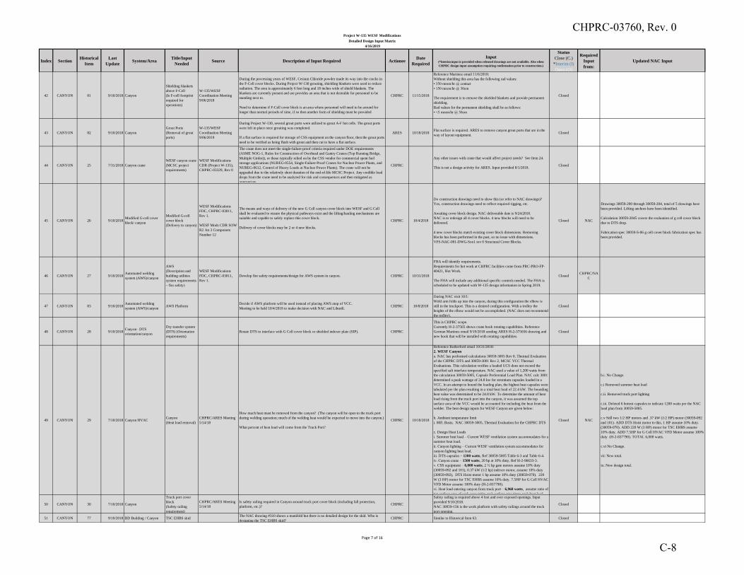
Index SectionHistorical
Item
Last
UpdateSystem/Area
Title/Input
NeededSource Description of Input Required Actionee
Date
Required
Input(*Interim input is provided when released drawings are not available. Also when
CHPRC design input assumption requiring confirmation prior to construction.)
Status
Close (C.)
*Interim (I)
Open (O)
Required
Input
from:
Updated NAC Input
Project W-135 WESF Modifications
Detailed Design Input Matrix
4/16/2019
42 CANYON 81 9/10/2018 Canyon
Shielding blankets
above F-Cell
(Is F-cell footprint
required for
operations)
W-135/WESF
Coordination Meeting
9/06/2018
During the processing years of WESF, Cesium Chloride powder made its way into the cracks in
the F-Cell cover blocks. During Project W-130 grouting, shielding blankets were used to reduce
radiation. The area is approximately 6 feet long and 18 inches wide of shield blankets. The
blankets are currently present and are provides an area that is not desirable for personnel to be
standing next to.
Need to determine if F-Cell cover block is an area where personnel will need to be around for
longer than normal periods of time, if so then another form of shielding must be provided
CHPRC 11/15/2018
Reference Martinez email 11/6/2018:
Without shielding this area has the following rad values:
• 350 mrem/hr @ contact
• 150 mrem/hr @ 30cm
The requirement is to remove the shielded blankets and provide permanent
shielding.
Rad values for the permanent shielding shall be as follows:
• <5 mrem/hr @ 30cm
Closed
43 CANYON 82 9/10/2018 Canyon
Grout Ports
(Removal of grout
ports)
W-135/WESF
Coordination Meeting
9/06/2019
During Project W-130, several grout ports were utilized to grout A-F hot cells. The grout ports
were left in place once grouting was completed.
If a flat surface is required for storage of CSS equipment on the canyon floor, then the grout ports
need to be verified as being flush with grout and then cut to have a flat surface.
ARES 10/18/2018Flat surface is required. ARES to remove canyon grout ports that are in the
way of layout equipment.Closed
44 CANYON 25 7/31/2018 Canyon crane
WESF canyon crane
(MCSC project
requirements)
WESF Modifications
CDR (Project W-135),
CHPRC-03329, Rev 0
The crane does not meet the single-failure-proof criteria required under DOE requirements
(ASME NOG-1, Rules for Construction of Overhead and Gantry Cranes (Top Running Bridge,
Multiple Girder)), or those typically relied on by the CSS vendor for commercial spent fuel
storage applications (NUREG-0554, Single-Failure-Proof Cranes for Nuclear Power Plants, and
NUREG-0612, Control of Heavy Loads at Nuclear Power Plants). The crane will not be
upgraded due to the relatively short duration of the end-of-life MCSC Project. Any credible load
drops from the crane need to be analyzed for risk and consequences and then mitigated as
appropriate.
CHPRC
Any other issues with crane that would affect project needs? See Item 24.
This is not a design activity for ARES. Input provided 8/1/2018.Closed
45 CANYON 26 9/10/2018Modified G-cell cover
block/ canyon
Modified G-cell
cover block
(Delivery to canyon)
WESF Modifications
FDC, CHPRC-03011,
Rev 1.
WESF Mods CDR SOW
R2 Att 3 Component
Number 12
The means and ways of delivery of the new G Cell canyon cover block into WESF and G Cell
shall be evaluated to ensure the physical pathways exist and the lifting/hauling mechanisms are
suitable and capable to safely replace this cover block.
Delivery of cover blocks may be 2 or 4 new blocks.
CHPRC 10/4/2018
Do construction drawings need to show this (or refer to NAC drawings)?
Yes, construction drawings need to reflect required rigging, etc.
Awaiting cover block design. NAC deliverable date is 9/24/2018.
NAC is to redesign all 4 cover blocks. 4 new blocks will need to be
delivered.
4 new cover blocks match existing cover block dimensions. Removing
blocks has been performed in the past, so no issue with dimensions.
VFS-NAC-001-DWG-Soo1 rev 0 Structural Cover Blocks.
Closed NAC
Drawings 30059-200 through 30059-204, total of 5 drawings have
been provided. Lifting anchors have been identified.
Calculation 30059-2045 covers the evaluation of g cell cover block
due to DTS drop.
Fabrication spec 30059-S-06 g cell cover block fabrication spec has
been provided.
46 CANYON 27 9/10/2018Automated welding
system (AWS)/canyon
AWS
(Description and
building utilities
system requirements
– fire safety)
WESF Modifications
FDC, CHPRC-03011,
Rev 1.
Develop fire safety requirements/design for AWS system in canyon. CHPRC 10/31/2018
FHA will identify requirements.
Requirements for hot work at CHPRC facilities come from PRC-PRO-FP-
40421, Hot Work.
The FHA will include any additional specific controls needed. The FHA is
scheduled to be updated with W-135 design information in Spring 2019.
ClosedCHPRC/NA
C
47 CANYON 83 9/10/2018Automated welding
system (AWS)/canyonAWS Platform
Decide if AWS platform will be used instead of placing AWS atop of VCC.
Meeting to be held 10/4/2018 to make decision with NAC and Liburdi.CHPRC 10/8/2018
During NAC visit 10/1:
Weld arm folds up into the canyon, during this configuration the elbow is
still in the truckport. This is a desired configuration. With a trolley the
heights of the elbow would not be accomplished. (NAC does not recommend
the trolley).
Closed
48 CANYON 28 9/10/2018Canyon– DTS
orientation/canyon
Dry transfer system
(DTS) (Orientation
requirements)
Rotate DTS to interface with G Cell cover block or shielded indexer plate (SIP). CHPRC
This is CHPRC scope.
Currently H-2-37565 shows crane hook rotating capabilities. Reference
German Martinez email 9/19/2018 sending ARES H-2-375656 drawing and
new hook that will be installed with rotating capabilities.
Closed
49 CANYON 29 7/10/2018 Canyon HVACCanyon
(Heat load removal)
CHPRC/ARES Meeting
5/14/18
How much heat must be removed from the canyon? (The canyon will be open to the truck port
during welding operation; much of the welding heat would be expected to move into the canyon.)
What percent of heat load will come from the Truck Port?
CHPRC 10/18/2018
Reference Rutherford email 10/31/2018:
2. WESF Canyon
a. NAC has performed calculations 30059-3005 Rev 0, Thermal Evaluation
of the CHPRC DTS and 30059-3001 Rev 2, MCSC VCC Thermal
Evaluations. This calculation verifies a loaded UCS does not exceed the
specified salt interface temperature. NAC used a value of 1,200 watts from
the calculation 30059-5005, Capsule Preferential Load Plan. NAC calc 3001
determined a peak wattage of 24.8 kw for strontium capsules loaded in a
VCC. In an attempt to bound the loading plan, the highest heat capsules were
tabulated per the plan resulting in a total heat load of 22.4 kW. The bounding
heat value was determined to be 24.8 kW. To determine the amount of heat
load rising from the truck port into the canyon, it was assumed the top
surface area of the VCC would be accounted for including the heat from the
welder. The heat design inputs for WESF Canyon are given below:
b. Ambient temperature limit
i. 80F; Basis; NAC 30059-3005, Thermal Evaluation for the CHPRC DTS
c. Design Heat Loads
i. Summer heat load – Current WESF ventilation system accommodates for a
summer heat load.
ii. Canyon lighting – Current WESF ventilation system accommodates for
canyon lighting heat load.
iii. DTS capsules – 1200 watts, Ref 30059-5005 Table 6-3 and Table 6-4.
iv. Canyon crane – 1500 watts, 20 hp at 10% duty, Ref H-2-96633-3.
v. CSS equipment – 6,000 watts, 2 ½ hp gate motors assume 10% duty
(30059-092 and 101), 0.37 kW (1/2 hp) indexer motor, assume 10% duty
(30059-092), DTS Hoist motor 1 hp assume 10% duty (30059-070). 220
W (3 HP) motor for TSC EHBS assume 10% duty. 7.5HP for G Cell HVAC
VFD Motor assume 100% duty (H-2-837790).
vi. Heat load entering canyon from truck port – 6,968 watts, assume ratio of
top surface area of cask over entire cask surface area times cask heat load
Closed NAC
b.i. No Change.
c.i Removed summer heat load
c.ii. Removed truck port lighting
c.iii. Deleted 6 hottest capsules to indicate 1200 watts per the NAC
load plan from 30059-5005.
c.v Still two 1/2 HP motors and .37 kW (1/2 HP) motor (30059-092
and 101). ADD DTS Hoist motor to this, 1 HP assume 10% duty.
(30059-070). ADD 220 W (3 HP) motor for TSC EHBS assume
10% duty. ADD 7.5HP for G Cell HVAC VFD Motor assume 100%
duty (H-2-837790). TOTAL 6,000 watts.
c.vi No Change.
vii: New total.
ix: New design total.
50 CANYON 30 7/10/2018 Canyon
Truck port cover
block
(Safety railing
requirement)
CHPRC/ARES Meeting
5/14/18
Is safety railing required in Canyon around truck port cover block (including fall protection,
platform, etc.)?CHPRC
Safety railing is required above 4 feet and over exposed openings. Input
provided 9/10/2018.
NAC 30059-156 is the work platform with safety railings around the truck
port opening.
Closed
51 CANYON 77 9/10/2018 BD Building / Canyon TSC EHBS skidThe NAC drawing #310 shows a manifold but there is no detailed design for the skid. Who is
designing the TSC EHBS skid?CHPRC Similar to Historical Item 63. Closed
Page 7 of 16
CHPRC-03760, Rev. 0
C-8
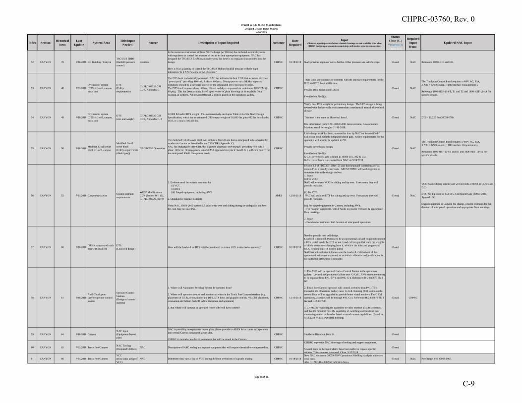
Index SectionHistorical
Item
Last
UpdateSystem/Area
Title/Input
NeededSource Description of Input Required Actionee
Date
Required
Input(*Interim input is provided when released drawings are not available. Also when
CHPRC design input assumption requiring confirmation prior to construction.)
Status
Close (C.)
*Interim (I)
Open (O)
Required
Input
from:
Updated NAC Input
Project W-135 WESF Modifications
Detailed Design Input Matrix
4/16/2019
52 CANYON 78 9/10/2018 BD Building / Canyon
TSC/UCS EHBS
(Backfill pressure
control)
Brandon
In the numerous instrument air lines NAC's design (w/ HiLine) has included a control system
with regulators to control the pressure of the air to their appropriate equipment. NAC has
designed the TSC/UCS EHBS manifold/system, but there is no regulator incorporated into the
design.
How is NAC planning to control the TSC/UCS Helium backfill pressure with the tight
tolerances? Is it NAC's scope or ARES scope?
CHPRC 10/18/2018 NAC provides regulator on He bottles. Other pressures are ARES scope. Closed NAC Reference 30059-310 and 313.
53 CANYON 48 7/31/2018
Dry transfer system
(DTS) / G-cell, canyon,
truck port
DTS
(Utility
requirements)
CHPRC-03326 CSS
CDR, Appendix C
The DTS hoist is electrically powered. NAC has indicated in their CDR that a custom electrical
“power pack” providing 480 volt, 3 phase, 60 hertz, 50 amp power via a NEMA approved
receptacle should be a sufficient source for the anticipated DTS hoist power needs.
The DTS itself requires clean, oil free, filtered and dry compressed air - minimum 10 SCFM @
90 psig. This has been assumed based upon review of plant drawings to be available from
existing air systems. All powered through 2 control panels in the operations gallery.
CHPRC
There is no known issues or concerns with the interface requirements for the
DTS and DTS hoist at this time.
Provide DTS design on 8/1/2018.
Provided on FileZilla.
Closed NAC
The Truckport Control Panel requires a 480V AC, 30A,
3 Pole + GND source. (FDR Interface Requirements).
Reference 1806-HEF-134-T, T1 and T2 and 1806-HEF-134-A for
specific details.
54 CANYON 49 7/10/2018
Dry transfer system
(DTS) / G-cell, canyon,
truck port
DTS
(size and weight)
CHPRC-03326 CSS
CDR, Appendix C, F
22,000 lb loaded DTS weight. This conservatively envelopes Table 4-3 of the NAC Design
Specification, which has an estimated DTS empty weight of 16,000 lbs, plus 400 lbs for a loaded
UCS, or a total of 16,400 lbs.
CHPRC
Verify final UCS weight for preliminary design. The UCS design is being
revised with thicker walls to accommodate a mechanical instead of a welded
closure.
This item is the same as Historical Item 1.
Use information from NAC-30059-2001 latest revision. Also reference
Martinez email for weights 11-19-2018.
Closed NAC DTS - 19,225 lbs (30059-070)
55 CANYON 50 9/10/2018Modified G-cell cover
block / G-cell, canyon
Modified G-cell
cover block
(Utility requirements
(shield gate))
NAC/WESF Operations
The modified G-Cell cover block will include a Shield Gate that is anticipated to be operated by
an electrical motor as described in the CSS CDR (Appendix C).
NAC has indicated in their CDR that a custom electrical “power pack” providing 480 volt, 3
phase, 60 hertz, 50 amp power via a NEMA approved receptacle should be a sufficient source for
the anticipated Shield Gate power needs.
CHPRC
Little design work has been presented to date by NAC on the modified G
Cell cover block with the integrated shield gate. Utility requirements for this
apparatus will need to be updated in PD.
Provide cover block design.
Provided on FileZilla.
G-Cell cover block gate is found in 30059-101, 102 & 103.
G-Cell cover block is expected from NAC on 9/24/2018.
Closed NAC
The Truckport Control Panel requires a 480V AC, 30A,
3 Pole + GND source. (FDR Interface Requirements).
Reference 1806-HEF-134-B and B1 and 1806-HEF-134-A for
specific details.
56 CANYON 52 7/31/2018 Canyon/truck portSeismic restraint
requirements
WESF Modifications
CDR (Project W-135),
CHPRC-03329, Rev 0
1. Evaluate need for seismic restraints for
(i) VCC
(ii) DTS
(iii) Staged equipment, including AWS.
2. Duration for seismic restraints.
Note: NAC 30059-2015 section 6.5 talks to tip-over and sliding during an earthquake and how
the cask may not do either.
ARES 12/30/2018
Section 2.2 of FDC 3011 (Rev. 2) says that structural constraints are "as
required" on a case-by-case basis. ARES/CHPRC will work together to
determine this as the design evolves.
1. Inputs
(i) For VCC:
NAC will evaluate VCC for sliding and tip over. If necessary they will
provide restraints.
(ii) For DTS:
NAC will evaluate DTS for sliding and tip over. If necessary they will
provide restraints.
(iii) For staged equipment in Canyon, including AWS.
- For "staged" equipment, WESF Mods to provide restraints & appropriate
floor markings.
2. Inputs
- Duration for restraints. Full duration of anticipated operations.
Closed NAC
VCC: Stable during seismic and will not slide. (30059-2015, 6.5 and
D.3)
DTS: No Tip-over on SIA or G Cell Shield Gate (30059-2015,
Appendix K).
Staged equipment in Canyon: No change, provide restraints for full
duration of anticipated operations and appropriate floor markings.
57 CANYON 60 9/10/2018DTS in canyon and truck
port/DTS load cell
DTS
(Load cell design) How will the load cell on DTS hoist be monitored to ensure UCS is attached or removed? CHPRC 10/18/2018
Need to provide load cell design.
Load cell is required. Purpose to be an operational aid and rough indication if
a UCS is still inside the DTS or not. Load cell is a pin that reads the weights
of all the components hanging from it, which is the hoist and grapple and
UCS. Readout on DTS control panel.
NAC has not evaluated tolerances on the load cell. Calibrations of this
operational aid are not expected, so an initial calibration and justification for
no calibration afterwards is desirable.
Closed
58 CANYON 61 9/10/2018
AWS-Truck port-
canyon/operator control
station
Operator Control
Stations
(Design of control
stations)
1. Where will Automated Welding System be operated from?
2. Where will operators control and monitor activities in the Truck Port/Canyon interface (e.g.
placement of UCSs, orientation of the DTS, DTS hoist and grapple controls, VCC lid placement,
evacuation and helium backfill, AWS placement and operation)
3. But where will cameras be operated from? Who will have control?
CHPRC 12/13/2018
1. The AWS will be operated from a Control Station in the operations
gallery. Located in Operations Gallery near G-Cell . AWS video monitoring
to be separate from PNL-TP-1 and PNL-G-4. Reference: H-2-837675 Sh. 1
&2.
2. Truck Port/Canyon operators will control activities from PNL-TP-1
located in the Operations Gallery near G-Cell. Existing PCO station on the
second floor will be upgraded to provide better visual monitors. For G Cell
operations, activities will be through PNL-G-4. Reference:H-2-837675 Sh. 1
&2 and H-2-837790.
3. CHPRC is requesting the capability to video monitor all CSS activities,
and that the monitors have the capability of switching controls from one
monitoring station to the other based on touch screen capabilities. (Based on
9/13/2018 W-135 IPD/SDIT meeting)
Closed CHPRC
59 CANYON 64 9/10/2018 Canyon
NAC Input
(Equipment layout
plan)
NAC is providing an equipment layout plan, please provide to ARES for accurate incorporation
into overall Canyon equipment layout plan.
CHPRC to provide clear list of equipment that will be stored in the Canyon.
CHPRC Similar to Historical Item 24. Closed
60 CANYON 65 7/31/2018 Truck Port/CanyonNAC Tooling
(Required Utilities)NAC Description of NAC tooling and support equipment that will require electrical or compressed air. CHPRC
CHPRC to provide NAC drawings of tooling and support equipment.
Several items in the Input Matrix have been added to request specific
utilities. This comment is general. Close. 9/12/2018.
Closed
61 CANYON 66 7/31/2018 Truck Port/Canyon
VCC
(Dose rates at top of
VCC)
NAC Determine dose rate at top of VCC during different evolutions of capsule loading CHPRC 10/18/2018
New NAC document 30059-5007 Operations Shielding Analysis addresses
dose rates.
Also CHPRC H-2-837959 indicates doses.
Closed NAC No change. See 30059-5007.
Page 8 of 16
CHPRC-03760, Rev. 0
C-9
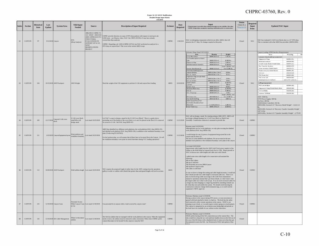
Index SectionHistorical
Item
Last
UpdateSystem/Area
Title/Input
NeededSource Description of Input Required Actionee
Date
Required
Input(*Interim input is provided when released drawings are not available. Also when
CHPRC design input assumption requiring confirmation prior to construction.)
Status
Close (C.)
*Interim (I)
Open (O)
Required
Input
from:
Updated NAC Input
Project W-135 WESF Modifications
Detailed Design Input Matrix
4/16/2019
62 CANYON 97 9/13/2018 CanyonDTS
(Drop Analysis)
18RL08314 CHPRC W-
135 / WESF - DISCUSS
ARES APPROACH TO
STRUCTURAL
EVALUATIONS IN
SUPPORT OF W-135
WESF
MODIFICATIONS
PROJECT
CHPRC provide direction on scope of DTS drop analysis with respect to truck port calc
S-004 (note – per Maurice Ades, NAC Calc 30059-2010 Rev 0 may have already
covered this drop analysis).
CHPRC: Regarding calc S-005 (CHPRC-03752), has NAC performed an analysis for a
DTS drop on canyon floor? This is not in the current ARES scope.
CHPRC 1/30/2019NAC is redesigning components which do not affect ARES, that will
preserve the 21" drop. No changes required at this point.Closed NAC
NAC has evaluated G Cell Cover blocks due to a 21" DTS drop.
This is consistent with what ARES has provided. (30059-2045).
63 CANYON 104 10/15/2018 AWS/Truckport AWS Weight Need the weight of the CSS equipment to perform G Cell and canyon floor loading. ARES 10/18/2018
Reference Dinse Email 10/15/2018.
Closed NAC
Canyon Loading: (FDR Interface Requirements)
AWS: 3500 lbs.
GTVI Power Supply: 600 lbs
FireView: 400 lbs
R30iB (Robot Controller): 265 lbs
30059-2002, Section 6.13 " Recovery Shield Weight" - 12,612.13
lbs.
30059-2002, Section 6.14 "Recovery Transfer Assembly Weight" -
1007.16 lbs.
30059-2002,, Section 6.15 "Upender Assembly Weight" - 2,778.50
lbs.
64 CANYON 109 12/17/2018Canyon/G Cell cover
block
G Cell cover block
stand/Who will
design stand
Lori email 10/25/2018
Is it NAC’s scope to design a stand for the G Cell Cover Block? There is a guide sleeve
protruding out of the bottom of the cover block, so it can’t be placed on the floor if it’s removed
for access to G Cell. Ref NAC dwg 30059-101.
CHPRC 11/15/2018
NAC will not design a stand. Per meeting minutes 18RL12071, ARES will
not design cribbage/dunnage for G Cell Cover Block or Shield Gate
Assembly. Construction contractor is assumed to provide this. Closed CHPRC
65 CANYON 111 2/23/2019 Canyon/Equipment layoutWork platform and
ventilation boundaryLori email 10/25/2018
ARES has identified two different work platforms, the work platform (NAC dwg 30059-155)
and shielded work platform (NAC dwg 30059-156), in addition to the ventilation boundary cover
plate (Veolia dwg H-2-837622).
For the laydown plan, we will assume that all three have to be stored flat in the Canyon. Or will
the ventilation boundary cover plate be stored elsewhere during VCC loading operations?
CHPRC 11/15/2018
Martinez email 10/29/2018:
Although there are two work platforms, we only plan on using the shielded
work platform (NAC dwg 30059-156).
I would design for one (1) pieces of equipment being stored flat in the
canyon and not three (3).
The one (1) is the shielded work platform. Do not account for the non
shielded work platform or the ventilation boundary cover plate in the canyon.
Closed CHPRC
66 CANYON 112 10/29/2018 AWS/Truckport Weld utilities length Lori email 10/25/2018NAC requires the proposed length of utility lines for the AWS coming from the operations
gallery in order to confirm with Liburdi that greater than anticipated lengths will not be an issue.ARES
Lori email 10/25/2018:
Approximate cable length from the AWS Gold Track power supply in Ops
Gallery to the Weld Head in Canyon/Truck Port is 170ft. Please provide to
NAC to discuss max cable lengths and cable sizes with Liburdi.
I added some extra cable length to be conservative and assumed the
following:
30ft in Ops Gallery
30ft up to 2nd floor
70ft horizontal run across MRS/Canyon
30ft up/down Canyon walls
10ft cable to weld head
In case we have to change the routing and cable length increases, I would ask
that Liburdi provide max cable length vs increased cable size. There is no
data on electrical lug (cable size) range in the Gold Track maintenance
manual or operations manual that I got from Liburdi, so I don’t know what
the largest cable size is that it will accept. If we do need oversized cables for
a longer run, then changing to a larger lug should be something Liburdi can
do when they test and modify the system. We should avoid directing the
construction contractor change field termination lugs, as it could void the
equipment’s NRTL approval.
Closed CHPRC
67 CANYON 125 12/19/2018 Canyon Crane
Personnel Access
While Canyon Crane
in Use
Lori email 12/18/2018 Can personnel be in canyon while a load is moved by canyon crane? CHPRC
Reference Martinez email 12/19/2018.
Having workers in the canyon during DTS moves, or crane movement in
general with load attached to hook, is a hard no. The hook has the safety
latch removed to allow remote operations in the canyon. WESF is not
planning to put it back, or it would require workers going in to latch/unlatch.
The canyon is categorized as an exclusion zone during high rad periods so
the hook has to be available for use without worker interaction.
Closed CHPRC
68 CANYON 126 12/19/2018 SIA Cable ManagementWhere to disconnect
utilitiesLori email 12/18/2018
The SIA has utilities that are managed with the work platform in the canyon. When the equipment
needs to move, the utilities must be removed to allow movement. Where does CHPRC prefer
connect/disconnect to be located? In the canyon or atop the SIA?
CHPRC
Reference Martinez email 12/19/2018.
WESF prefers having all the SIA connections up on the canyon floor. The
idea would be to drop the two cord and hose bundles down on the SIA out of
the way of the lift fixture with a shepherds hook of some sort when they get
disconnected to move the SIA. Jay Westwood of NAC had spoken of that
before.
Closed
Page 9 of 16
CHPRC-03760, Rev. 0
C-10
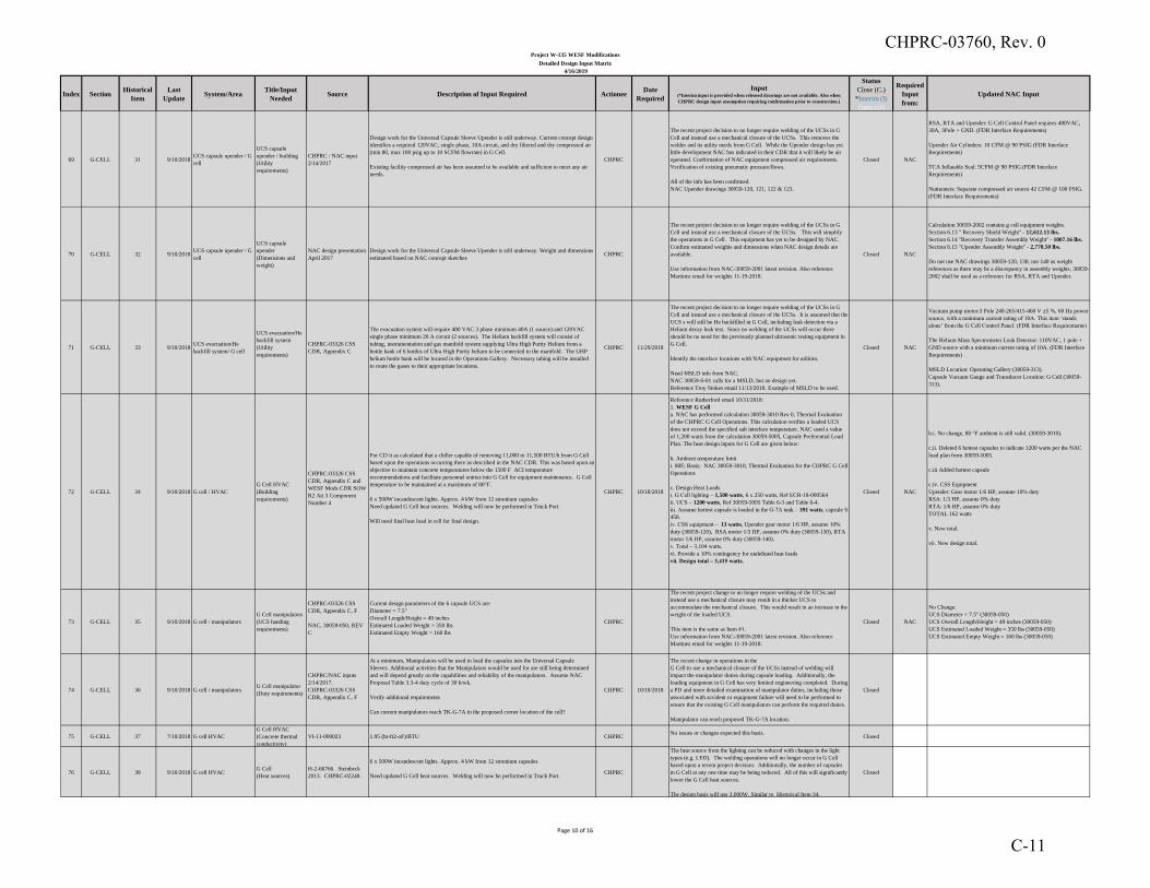
Index SectionHistorical
Item
Last
UpdateSystem/Area
Title/Input
NeededSource Description of Input Required Actionee
Date
Required
Input(*Interim input is provided when released drawings are not available. Also when
CHPRC design input assumption requiring confirmation prior to construction.)
Status
Close (C.)
*Interim (I)
Open (O)
Required
Input
from:
Updated NAC Input
Project W-135 WESF Modifications
Detailed Design Input Matrix
4/16/2019
69 G-CELL 31 9/10/2018UCS capsule upender / G
cell
UCS capsule
upender / building
(Utility
requirements)
CHPRC / NAC input
2/14/2017
Design work for the Universal Capsule Sleeve Upender is still underway. Current concept design
identifies a required 120VAC, single phase, 10A circuit, and dry filtered and dry compressed air
(min 80, max 100 psig up to 10 SCFM flowrate) in G Cell.
Existing facility compressed air has been assumed to be available and sufficient to meet any air
needs.
CHPRC
The recent project decision to no longer require welding of the UCSs in G
Cell and instead use a mechanical closure of the UCSs. This removes the
welder and its utility needs from G Cell. While the Upender design has yet
little development NAC has indicated in their CDR that it will likely be air
operated. Confirmation of NAC equipment compressed air requirements.
Verification of existing pneumatic pressure/flows.
All of the info has been confirmed.
NAC Upender drawings 30059-120, 121, 122 & 123.
Closed NAC
RSA, RTA and Upender: G Cell Control Panel requires 480VAC,
30A, 3Pole + GND. (FDR Interface Requirements)
Upender Air Cylinders: 10 CFM @ 90 PSIG (FDR Interface
Requirements)
TCA Inflatable Seal: 5CFM @ 90 PSIG (FDR Interface
Requirements)
Nuttunners: Separate compressed air source 42 CFM @ 100 PSIG.
(FDR Interface Requirements)
70 G-CELL 32 9/10/2018UCS capsule upender / G
cell
UCS capsule
upender
(Dimensions and
weight)
NAC design presentation
April 2017
Design work for the Universal Capsule Sleeve Upender is still underway. Weight and dimensions
estimated based on NAC concept sketchesCHPRC
The recent project decision to no longer require welding of the UCSs in G
Cell and instead use a mechanical closure of the UCSs. This will simplify
the operations in G Cell. This equipment has yet to be designed by NAC.
Confirm estimated weights and dimensions when NAC design details are
available.
Use information from NAC-30059-2001 latest revision. Also reference
Martinez email for weights 11-19-2018.
Closed NAC
Calculation 30059-2002 contains g cell equipment weights.
Section 6.13 " Recovery Shield Weight" - 12,612.13 lbs.
Section 6.14 "Recovery Transfer Assembly Weight" - 1007.16 lbs.
Section 6.15 "Upender Assembly Weight" - 2,778.50 lbs.
Do not use NAC drawings 30059-120, 130, nor 140 as weight
references as there may be a discrepancy in assembly weights. 30059-
2002 shall be used as a reference for RSA, RTA and Upender.
71 G-CELL 33 9/10/2018UCS evacuation/He
backfill system/ G cell
UCS evacuation/He
backfill system
(Utility
requirements)
CHPRC-03326 CSS
CDR, Appendix C
The evacuation system will require 480 VAC 3 phase minimum 40A (1 source) and 120VAC
single phase minimum 20 A circuit (2 sources). The Helium backfill system will consist of
tubing, instrumentation and gas manifold system supplying Ultra High Purity Helium from a
bottle bank of 6 bottles of Ultra High Purity helium to be connected to the manifold. The UHP
helium bottle bank will be located in the Operations Gallery. Necessary tubing will be installed
to route the gases to their appropriate locations.
CHPRC 11/29/2018
The recent project decision to no longer require welding of the UCSs in G
Cell and instead use a mechanical closure of the UCSs. It is assumed that the
UCS s will still be He backfilled in G Cell, including leak detection via a
Helium decay leak test. Since no welding of the UCSs will occur there
should be no need for the previously planned ultrasonic testing equipment in
G Cell.
Identify the interface locations with NAC equipment for utilities.
Need MSLD info from NAC.
NAC 30059-S-01 calls for a MSLD, but no design yet.
Reference Troy Stokes email 11/13/2018. Example of MSLD to be used.
Closed NAC
Vacuum pump motor:3 Pole 240-265/415-460 V ±5 %, 60 Hz power
source, with a minimum current rating of 10A. This item ‘stands
alone’ from the G Cell Control Panel. (FDR Interface Requirements)
The Helium Mass Spectrometer Leak Detector: 110VAC, 1 pole +
GND source with a minimum current rating of 10A. (FDR Interface
Requirements)
MSLD Location: Operating Gallery (30059-313).
Capsule Vacuum Gauge and Transducer Location: G Cell (30059-
313).
72 G-CELL 34 9/10/2018 G cell / HVAC
G Cell HVAC
(Building
requirements)
CHPRC-03326 CSS
CDR, Appendix C and
WESF Mods CDR SOW
R2 Att 3 Component
Number 4
For CD it as calculated that a chiller capable of removing 11,000 to 11,500 BTU/h from G Cell
based upon the operations occurring there as described in the NAC CDR. This was based upon an
objective to maintain concrete temperatures below the 1500 F ACI temperature
recommendations and facilitate personnel entries into G Cell for equipment maintenance. G Cell
temperature to be maintained at a maximum of 80°F.
6 x 500W incandescent lights. Approx. 4 kW from 12 strontium capsules
Need updated G Cell heat sources. Welding will now be performed in Truck Port.
Will need final heat load in cell for final design.
CHPRC 10/18/2018
Reference Rutherford email 10/31/2018:
1. WESF G Cell
a. NAC has performed calculation 30059-3010 Rev 0, Thermal Evaluation
of the CHPRC G Cell Operations. This calculation verifies a loaded UCS
does not exceed the specified salt interface temperature. NAC used a value
of 1,200 watts from the calculation 30059-5005, Capsule Preferential Load
Plan. The heat design inputs for G Cell are given below:
b. Ambient temperature limit
i. 80F; Basis; NAC 30059-3010, Thermal Evaluation for the CHPRC G Cell
Operations
c. Design Heat Loads
i. G Cell lighting – 1,500 watts, 6 x 250 watts, Ref ECR-18-000564
ii. UCS – 1200 watts, Ref 30059-5005 Table 6-3 and Table 6-4.
iii. Assume hottest capsule is loaded in the G-7A tank – 391 watts, capsule S-
458.
iv. CSS equipment – 13 watts, Upender gear motor 1/6 HP, assume 10%
duty (30059-120), RSA motor 1/3 HP, assume 0% duty (30059-130), RTA
motor 1/6 HP, assume 0% duty (30059-140).
v. Total – 3,104 watts.
vi. Provide a 10% contingency for undefined heat loads
vii. Design total – 3,415 watts.
Closed NAC
b.i. No change, 80 °F ambient is still valid. (30059-3010).
c.ii. Deleted 6 hottest capsules to indicate 1200 watts per the NAC
load plan from 30059-5005.
c.iii Added hottest capsule
c.iv. CSS Equipment
Upender: Gear motor 1/6 HP, assume 10% duty
RSA: 1/3 HP, assume 0% duty
RTA: 1/6 HP, assume 0% duty
TOTAL 162 watts
v. New total.
vii. New design total.
73 G-CELL 35 9/10/2018 G cell / manipulators
G Cell manipulators
(UCS handing
requirements)
CHPRC-03326 CSS
CDR, Appendix C, F
NAC, 30059-050, REV
C
Current design parameters of the 6 capsule UCS are:
Diameter = 7.5"
Overall Length/Height = 49 inches
Estimated Loaded Weight = 350 lbs
Estimated Empty Weight = 160 lbs
CHPRC
The recent project change to no longer require welding of the UCSs and
instead use a mechanical closure may result in a thicker UCS to
accommodate the mechanical closure. This would result in an increase in the
weight of the loaded UCS.
This item is the same as Item #1.
Use information from NAC-30059-2001 latest revision. Also reference
Martinez email for weights 11-19-2018.
Closed NAC
No Change:
UCS Diameter = 7.5" (30059-050)
UCS Overall Length/Height = 49 inches (30059-050)
UCS Estimated Loaded Weight = 350 lbs (30059-050)
UCS Estimated Empty Weight = 160 lbs (30059-050)
74 G-CELL 36 9/10/2018 G cell / manipulators G Cell manipulator
(Duty requirements)
CHPRC/NAC inputs
2/14/2017.
CHPRC-03326 CSS
CDR, Appendix C, F
At a minimum, Manipulators will be used to load the capsules into the Universal Capsule
Sleeves. Additional activities that the Manipulators would be used for are still being determined
and will depend greatly on the capabilities and reliability of the manipulators. Assume NAC
Proposal Table 3.3-4 duty cycle of 30 h/wk.
Verify additional requirements
Can current manipulators reach TK-G-7A in the proposed corner location of the cell?
CHPRC 10/18/2018
The recent change in operations in the
G Cell to use a mechanical closure of the UCSs instead of welding will
impact the manipulator duties during capsule loading. Additionally, the
loading equipment in G Cell has very limited engineering completed. During
a PD and more detailed examination of manipulator duties, including those
associated with accident or equipment failure will need to be performed to
ensure that the existing G Cell manipulators can perform the required duties.
Manipulator can reach proposed TK-G-7A location.
Closed
75 G-CELL 37 7/10/2018 G cell HVAC
G Cell HVAC
(Concrete thermal
conductivity)
VI-11-000023 1.95 (hr-ft2-oF)/BTU CHPRC No issues or changes expected this basis.
Closed
76 G-CELL 38 9/10/2018 G cell HVAC G Cell
(Heat sources)
H-2-66766. Steinbeck
2013. CHPRC-02248.
6 x 500W incandescent lights. Approx. 4 kW from 12 strontium capsules
Need updated G Cell heat sources. Welding will now be performed in Truck Port.CHPRC
The heat source from the lighting can be reduced with changes in the light
types (e.g. LED). The welding operations will no longer occur in G Cell
based upon a recent project decision. Additionally, the number of capsules
in G Cell at any one time may be being reduced. All of this will significantly
lower the G Cell heat sources.
The design basis will use 3,000W. Similar to Historical Item 34.
Closed
Page 10 of 16
CHPRC-03760, Rev. 0
C-11
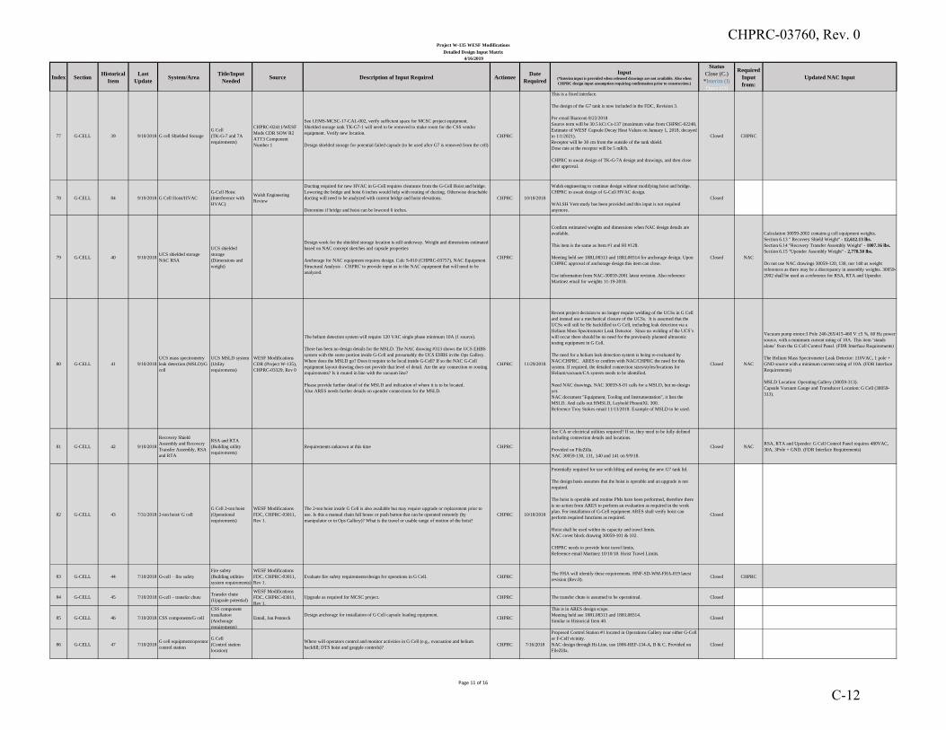
Index SectionHistorical
Item
Last
UpdateSystem/Area
Title/Input
NeededSource Description of Input Required Actionee
Date
Required
Input(*Interim input is provided when released drawings are not available. Also when
CHPRC design input assumption requiring confirmation prior to construction.)
Status
Close (C.)
*Interim (I)
Open (O)
Required
Input
from:
Updated NAC Input
Project W-135 WESF Modifications
Detailed Design Input Matrix
4/16/2019
77 G-CELL 39 9/10/2018 G cell Shielded Storage
G Cell
(TK-G-7 and 7A
requirements)
CHPRC-02411/WESF
Mods CDR SOW R2
ATT3 Component
Number 1
See LEMS-MCSC-17-CAL-002, verify sufficient space for MCSC project equipment.
Shielded storage tank TK-G7-1 will need to be removed to make room for the CSS vendor
equipment. Verify new location.
Design shielded storage for potential failed capsule (to be used after G7 is removed from the cell)
CHPRC
This is a fixed interface.
The design of the G7 tank is now included in the FDC, Revision 3.
Per email Bianconi 8/22/2018
Source term will be 30.5 kCi Cs-137 (maximum value from CHPRC-02248,
Estimate of WESF Capsule Decay Heat Values on January 1, 2018, decayed
to 1/1/2021).
Receptor will be 30 cm from the outside of the tank shield.
Dose rate at the receptor will be 5 mR/h.
CHPRC to await design of TK-G-7A design and drawings, and then close
after approval.
Closed CHPRC
78 G-CELL 84 9/10/2018 G Cell Hoist/HVAC
G-Cell Hoist
(Interference with
HVAC)
Walsh Engineering
Review
Ducting required for new HVAC in G-Cell requires clearance from the G-Cell Hoist and bridge.
Lowering the bridge and hoist 6 inches would help with routing of ducting. Otherwise detachable
ducting will need to be analyzed with current bridge and hoist elevations.
Determine if bridge and hoist can be lowered 6 inches.
CHPRC 10/18/2018
Walsh engineering to continue design without modifying hoist and bridge.
CHPRC to await design of G-Cell HVAC design.
WALSH Vent study has been provided and this input is not required
anymore.
Closed
79 G-CELL 40 9/10/2018UCS shielded storage
NAC RSA
UCS shielded
storage
(Dimensions and
weight)
Design work for the shielded storage location is still underway. Weight and dimensions estimated
based on NAC concept sketches and capsule properties
Anchorage for NAC equipment requires design. Calc S-010 (CHPRC-03757), NAC Equipment
Structural Analysis – CHPRC to provide input as to the NAC equipment that will need to be
analyzed.
CHPRC
Confirm estimated weights and dimensions when NAC design details are
available.
This item is the same as Item #1 and HI #128.
Meeting held see 18RL08313 and 18RL08314 for anchorage design. Upon
CHPRC approval of anchorage design this item can close.
Use information from NAC-30059-2001 latest revision. Also reference
Martinez email for weights 11-19-2018.
Closed NAC
Calculation 30059-2002 contains g cell equipment weights.
Section 6.13 " Recovery Shield Weight" - 12,612.13 lbs.
Section 6.14 "Recovery Transfer Assembly Weight" - 1007.16 lbs.
Section 6.15 "Upender Assembly Weight" - 2,778.50 lbs.
Do not use NAC drawings 30059-120, 130, nor 140 as weight
references as there may be a discrepancy in assembly weights. 30059-
2002 shall be used as a reference for RSA, RTA and Upender.
80 G-CELL 41 9/10/2018
UCS mass spectrometry
leak detection (MSLD)/G
cell
UCS MSLD system
(Utility
requirements)
WESF Modifications
CDR (Project W-135),
CHPRC-03329, Rev 0
The helium detection system will require 120 VAC single phase minimum 10A (1 source).
There has been no design details for the MSLD. The NAC drawing #313 shows the UCS EHBS
system with the some portion inside G-Cell and presumably the UCS EHBS in the Ops Gallery.
Where does the MSLD go? Does it require to be local inside G-Cell? If so the NAC G-Cell
equipment layout drawing does not provide that level of detail. Are the any connection or routing
requirements? Is it routed in line with the vacuum line?
Please provide further detail of the MSLD and indication of where it is to be located.
Also ARES needs further details on upender connections for the MSLD.
CHPRC 11/29/2018
Recent project decision to no longer require welding of the UCSs in G Cell
and instead use a mechanical closure of the UCSs. It is assumed that the
UCSs will still be He backfilled in G Cell, including leak detection via a
Helium Mass Spectrometer Leak Detector. Since no welding of the UCS’s
will occur there should be no need for the previously planned ultrasonic
testing equipment in G Cell.
The need for a helium leak detection system is being re-evaluated by
NAC/CHPRC. ARES to confirm with NAC/CHPRC the need for this
system. If required, the detailed connection sizes/styles/locations for
Helium/vacuum/CA system needs to be identified.
Need NAC drawings. NAC 30059-S-01 calls for a MSLD, but no design
yet.
NAC document "Equipment, Tooling and Instrumentation", it lists the
MSLD. And calls out HMSLD, Leybold PhoeniXL 300.
Reference Troy Stokes email 11/13/2018. Example of MSLD to be used.
Closed NAC
Vacuum pump motor:3 Pole 240-265/415-460 V ±5 %, 60 Hz power
source, with a minimum current rating of 10A. This item ‘stands
alone’ from the G Cell Control Panel. (FDR Interface Requirements)
The Helium Mass Spectrometer Leak Detector: 110VAC, 1 pole +
GND source with a minimum current rating of 10A. (FDR Interface
Requirements)
MSLD Location: Operating Gallery (30059-313).
Capsule Vacuum Gauge and Transducer Location: G Cell (30059-
313).
81 G-CELL 42 9/10/2018
Recovery Shield
Assembly and Recovery
Transfer Assembly, RSA
and RTA
RSA and RTA
(Building utility
requirements)
Requirements unknown at this time CHPRC
Are CA or electrical utilities required? If so, they need to be fully defined
including connection details and locations.
Provided on FileZilla.
NAC 30059-130, 131, 140 and 141 on 9/9/18.
Closed NACRSA, RTA and Upender: G Cell Control Panel requires 480VAC,
30A, 3Pole + GND. (FDR Interface Requirements)
82 G-CELL 43 7/31/2018 2-ton hoist/ G cell
G Cell 2-ton hoist
(Operational
requirements)
WESF Modifications
FDC, CHPRC-03011,
Rev 1.
The 2-ton hoist inside G Cell is also available but may require upgrade or replacement prior to
use. Is this a manual chain fall house or push button that can be operated remotely (by
manipulator or in Ops Gallery)? What is the travel or usable range of motion of the hoist?
CHPRC 10/18/2018
Potentially required for use with lifting and moving the new G7 tank lid.
The design basis assumes that the hoist is operable and an upgrade is not
required.
The hoist is operable and routine PMs have been performed, therefore there
is no action from ARES to perform an evaluation as required in the work
plan. For installation of G-Cell equipment ARES shall verify hoist can
perform required functions as required.
Hoist shall be used within its capacity and travel limits.
NAC cover block drawing 30059-101 & 102.
CHPRC needs to provide hoist travel limits.
Reference email Martinez 10/10/18. Hoist Travel Limits.
Closed
83 G-CELL 44 7/10/2018 G-cell – fire safety
Fire safety
(Building utilities
system requirements)
WESF Modifications
FDC, CHPRC-03011,
Rev 1.
Evaluate fire safety requirements/design for operations in G Cell. CHPRC The FHA will identify these requirements. HNF-SD-WM-FHA-019 latest
revision (Rev.8).Closed CHPRC
84 G-CELL 45 7/10/2018 G-cell – transfer chuteTransfer chute
(Upgrade potential)
WESF Modifications
FDC, CHPRC-03011,
Rev 1.
Upgrade as required for MCSC project. CHPRC The transfer chute is assumed to be operational. Closed
85 G-CELL 46 7/10/2018 CSS components/G cell
CSS component
installation
(Anchorage
requirements)
Email, Jan PennockDesign anchorage for installation of G Cell capsule loading equipment.
CHPRC
This is in ARES design scope.
Meeting held see 18RL08313 and 18RL08314.
Similar to Historical Item 40.Closed
86 G-CELL 47 7/10/2018G cell equipment/operator
control station
G Cell
(Control station
location)
Where will operators control and monitor activities in G Cell (e.g., evacuation and helium
backfill; DTS hoist and grapple controls)?CHPRC 7/16/2018
Proposed Control Station #1 located in Operations Gallery near either G-Cell
or F-Cell vicinity.
NAC design through Hi-Line, use 1806-HEF-134-A, B & C. Provided on
FileZilla.
Closed
Page 11 of 16
CHPRC-03760, Rev. 0
C-12
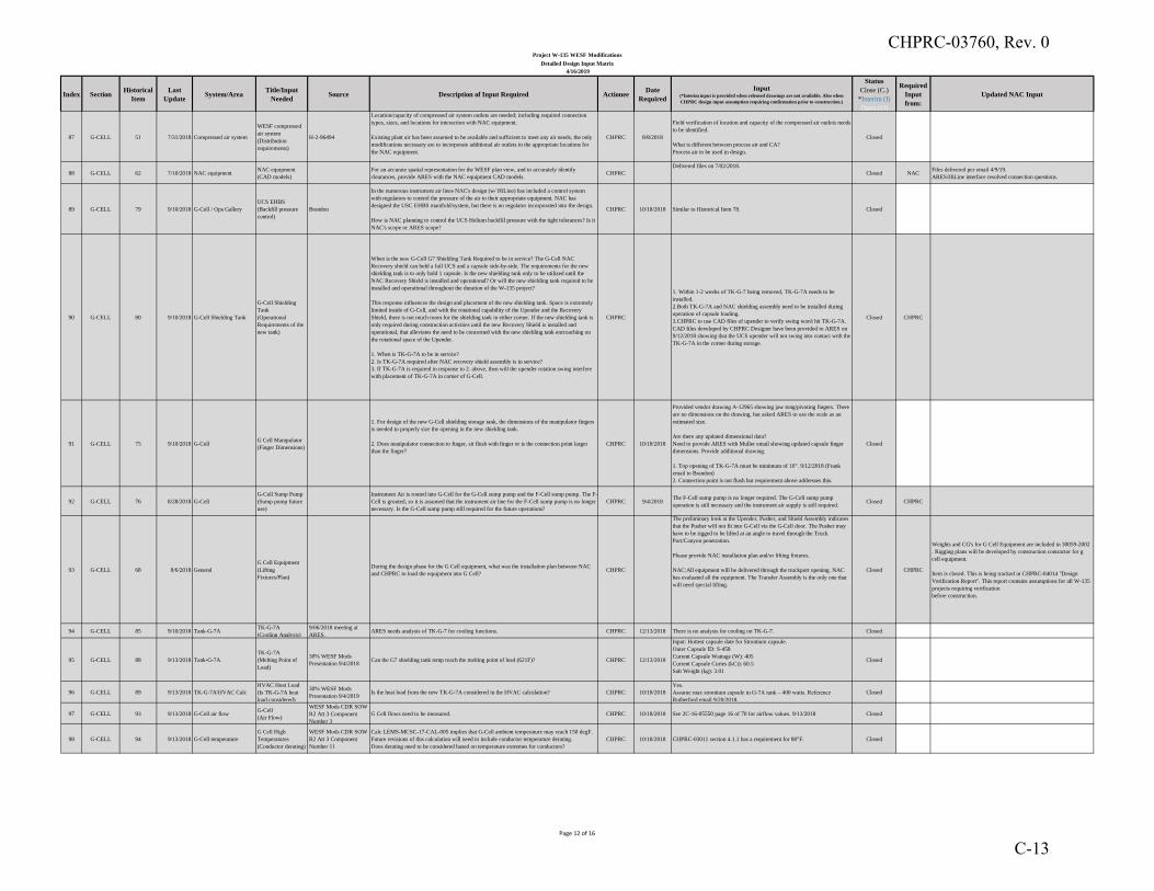
Index SectionHistorical
Item
Last
UpdateSystem/Area
Title/Input
NeededSource Description of Input Required Actionee
Date
Required
Input(*Interim input is provided when released drawings are not available. Also when
CHPRC design input assumption requiring confirmation prior to construction.)
Status
Close (C.)
*Interim (I)
Open (O)
Required
Input
from:
Updated NAC Input
Project W-135 WESF Modifications
Detailed Design Input Matrix
4/16/2019
87 G-CELL 51 7/31/2018 Compressed air system
WESF compressed
air system
(Distribution
requirements)
H-2-96494
Location/capacity of compressed air system outlets are needed; including required connection
types, sizes, and locations for interaction with NAC equipment.
Existing plant air has been assumed to be available and sufficient to meet any air needs, the only
modifications necessary are to incorporate additional air outlets in the appropriate locations for
the NAC equipment.
CHPRC 8/8/2018
Field verification of location and capacity of the compressed air outlets needs
to be identified.
What is different between process air and CA?
Process air to be used in design.
Closed
88 G-CELL 62 7/10/2018 NAC equipmentNAC equipment
(CAD models)
For an accurate spatial representation for the WESF plan view, and to accurately identify
clearances, provide ARES with the NAC equipment CAD models.CHPRC
Delivered files on 7/02/2018.
Closed NACFiles delivered per email 4/9/19.
ARES/HiLine interface resolved connection questions.
89 G-CELL 79 9/10/2018 G-Cell / Ops Gallery
UCS EHBS
(Backfill pressure
control)
Brandon
In the numerous instrument air lines NAC's design (w/ HiLine) has included a control system
with regulators to control the pressure of the air to their appropriate equipment. NAC has
designed the USC EHBS manifold/system, but there is no regulator incorporated into the design.
How is NAC planning to control the UCS Helium backfill pressure with the tight tolerances? Is it
NAC's scope or ARES scope?
CHPRC 10/18/2018 Similar to Historical Item 78. Closed
90 G-CELL 80 9/10/2018 G-Cell Shielding Tank
G-Cell Shielding
Tank
(Operational
Requirements of the
new tank)
When is the new G-Cell G7 Shielding Tank Required to be in service? The G-Cell NAC
Recovery shield can hold a full UCS and a capsule side-by-side. The requirements for the new
shielding tank is to only hold 1 capsule. Is the new shielding tank only to be utilized until the
NAC Recovery Shield is installed and operational? Or will the new shielding tank required to be
installed and operational throughout the duration of the W-135 project?
This response influences the design and placement of the new shielding tank. Space is extremely
limited inside of G-Cell, and with the rotational capability of the Upender and the Recovery
Shield, there is not much room for the shielding tank in either corner. If the new shielding tank is
only required during construction activities until the new Recovery Shield is installed and
operational, that alleviates the need to be concerned with the new shielding tank encroaching on
the rotational space of the Upender.
1. When is TK-G-7A to be in service?
2. Is TK-G-7A required after NAC recovery shield assembly is in service?
3. If TK-G-7A is required in response to 2. above, then will the upender rotation swing interfere
with placement of TK-G-7A in corner of G-Cell.
CHPRC
1. Within 1-2 weeks of TK-G-7 being removed, TK-G-7A needs to be
installed.
2.Both TK-G-7A and NAC shielding assembly need to be installed during
operation of capsule loading.
3.CHPRC to use CAD files of upender to verify swing won't hit TK-G-7A.
CAD files developed by CHPRC Designer have been provided to ARES on
9/12/2018 showing that the UCS upender will not swing into contact with the
TK-G-7A in the corner during storage.
Closed CHPRC
91 G-CELL 75 9/10/2018 G-CellG Cell Manipulator
(Finger Dimensions)
1. For design of the new G-Cell shielding storage tank, the dimensions of the manipulator fingers
is needed to properly size the opening in the new shielding tank.
2. Does manipulator connection to finger, sit flush with finger or is the connection point larger
than the finger?
CHPRC 10/18/2018
Provided vendor drawing A-12965 showing jaw tong/pivoting fingers. There
are no dimensions on the drawing, but asked ARES to use the scale as an
estimated size.
Are there any updated dimensional data?
Need to provide ARES with Muller email showing updated capsule finger
dimensions. Provide additional drawing.
1. Top opening of TK-G-7A must be minimum of 10". 9/12/2018 (Frank
email to Brandon)
2. Connection point is not flush but requirement above addresses this.
Closed
92 G-CELL 76 8/28/2018 G-Cell
G-Cell Sump Pump
(Sump pump future
use)
Instrument Air is routed into G-Cell for the G-Cell sump pump and the F-Cell sump pump. The F-
Cell is grouted, so it is assumed that the instrument air line for the F-Cell sump pump is no longer
necessary. Is the G-Cell sump pump still required for the future operations?
CHPRC 9/4/2018The F-Cell sump pump is no longer required. The G-Cell sump pump
operation is still necessary and the instrument air supply is still required.Closed CHPRC
93 G-CELL 68 8/6/2018 General
G Cell Equipment
(Lifting
Fixtures/Plan)
During the design phase for the G Cell equipment, what was the installation plan between NAC
and CHPRC to load the equipment into G Cell? CHPRC
The preliminary look at the Upender, Pusher, and Shield Assembly indicates
that the Pusher will not fit into G-Cell via the G-Cell door. The Pusher may
have to be rigged to be lifted at an angle to travel through the Truck
Port/Canyon penetration.
Please provide NAC installation plan and/or lifting fixtures.
NAC:All equipment will be delivered through the truckport opening. NAC
has evaluated all the equipment. The Transfer Assembly is the only one that
will need special lifting.
Closed CHPRC
Weights and CG's for G Cell Equipment are included in 30059-2002
. Rigging plans will be developed by construction contractor for g
cell equipment.
Item is closed. This is being tracked in CHPRC-04014 "Design
Verification Report". This report contains assumptions for all W-135
projects requiring verification
before construction.
94 G-CELL 85 9/10/2018 Tank-G-7ATK-G-7A
(Cooling Analysis)
9/06/2018 meeting at
ARES.ARES needs analysis of TK-G-7 for cooling functions. CHPRC 12/13/2018 There is no analysis for cooling on TK-G-7. Closed
95 G-CELL 88 9/13/2018 Tank-G-7A
TK-G-7A
(Melting Point of
Lead)
30% WESF Mods
Presentation 9/4/2018Can the G7 shielding tank temp reach the melting point of lead (621F)? CHPRC 12/13/2018
Input: Hottest capsule date for Strontium capsule.
Outer Capsule ID: S-458
Current Capsule Wattage (W): 405
Current Capsule Curies (kCi): 60.5
Salt Weight (kg): 3.01
Closed
96 G-CELL 89 9/13/2018 TK-G-7A/HVAC Calc
HVAC Heat Load
(Is TK-G-7A heat
load considered)
30% WESF Mods
Presentation 9/4/2019Is the heat load from the new TK-G-7A considered in the HVAC calculation? CHPRC 10/18/2018
Yes.
Assume max strontium capsule in G-7A tank – 400 watts. Reference
Rutherford email 9/20/2018.
Closed
97 G-CELL 93 9/13/2018 G-Cell air flowG-Cell
(Air Flow)
WESF Mods CDR SOW
R2 Att 3 Component
Number 3
G Cell flows need to be measured. CHPRC 10/18/2018 See 2C-16-05550 page 16 of 70 for airflow values. 9/13/2018 Closed
98 G-CELL 94 9/13/2018 G-Cell temperature
G Cell High
Temperatures
(Conductor derating)
WESF Mods CDR SOW
R2 Att 3 Component
Number 11
Calc LEMS-MCSC-17-CAL-005 implies that G-Cell ambient temperature may reach 150 degF.
Future revisions of this calculation will need to include conductor temperature derating.
Does derating need to be considered based on temperature extremes for conductors?
CHPRC 10/18/2018 CHPRC-03011 section 4.1.1 has a requirement for 80°F. Closed
Page 12 of 16
CHPRC-03760, Rev. 0
C-13
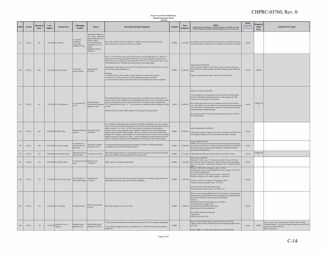
Index SectionHistorical
Item
Last
UpdateSystem/Area
Title/Input
NeededSource Description of Input Required Actionee
Date
Required
Input(*Interim input is provided when released drawings are not available. Also when
CHPRC design input assumption requiring confirmation prior to construction.)
Status
Close (C.)
*Interim (I)
Open (O)
Required
Input
from:
Updated NAC Input
Project W-135 WESF Modifications
Detailed Design Input Matrix
4/16/2019
99 G-CELL 98 9/13/2018 G-Cell Hoist
G Cell Hoist
Calculation
(Calc S-008
(CHPRC-03755))
18RL08314 CHPRC W-
135 / WESF - DISCUSS
ARES APPROACH TO
STRUCTURAL
EVALUATIONS IN
SUPPORT OF W-135
WESF
MODIFICATIONS
PROJECT
Calc S-008 (CHPRC-03755), G-Cell Hoist – CHPRC to provide direction on the scope
of this calculation. It may turn out that it is not required.CHPRC 11/15/2018
For loading a UCS into Upender, hoist can be used. Travel limits are known,
and other operations would need to be evaluated to be inside the travel limits.Closed
100 G-CELL 100 9/24/2018 G-Cell Air FiltersG Cell Filter
(Filter removal)
Brandon Email
9/21/2018
In Rev 11 of H-2-67092 you’ll see the Cell Air Filter in zones D6 and D8 (K3-2-1 and K3-2-2
respectively). NAC has the placement of their Recovery Transfer Assembly in the location of
both of these Cell Air Filters (see NAC dwg 30059-110 sht 2). You’ll notice that in Rev 12 of H-
2-67092 that the K3-2-1 Air Filter is removed (except for an outline square).
Unfortunately I don’t think you can see the Cell Air Filters from the G Cell windows, so I’m not
sure what the current configuration is.
Questions:
1. With all of the new HVAC plans, are either of the Cell Air Filters still required?
2. Is the K3-2-1 air filter removed, or is that a drafting error between revisions?
3. Can both of the air filters be removed to make room for the Recovery Transfer Assembly?
CHPRC 10/18/2018
Rutherford email 9/24/2018.
I have been told 6” flanges are left in floor. Need to verify no interference
issues with UCS transfer assembly. Duct below flanges has been filled with
grout.
Flanges can be removed to make G cell floor level for the RTA.
Closed CHPRC
101 G-CELL 101 9/25/2018 G Cell PenetrationsCut or shorten 295
and 13
Hanford Interface
Requirements Document
August 23, 2018
NAC Hanford Interface document states the following, "In addition to the pipe that needs to be
removed, NAC has also identified two wall penetrations that need to be cut or shortened to ensure
they do not protrude more than 4” from the wall. The exact locations look to be penetrations
“295” and directly below that, “13”. These locations were identified to Marie Gillespie on March
8, 2018."
Will this modification affect ARES intentions of utilizing both wall penetrations?
ARES 10/18/2018
Email, Lori Weidner 10/02/2018.
"We’ll abandon the use of penetrations G13 and G295 for electrical cables
since the combination of penetration stub out, connector/plug, and cable
would stick out more than 4” from the wall.
We’ll change the design to only use penetrations from the Service Gallery
side. This enables us to route cables as far as possible from the capsule chute
to minimize dose on cable insulation, and also to avoid interference with the
transfer assembly and shield assembly.
We’re going to model G Cell in Inventor during final design, so we’ll fold
this into the model."
ClosedCHPRC/NA
C
102 G-CELL 102 10/10/2018 K3 HEPA FilterDifferential Pressure
Capacity
Dave Keller email:
10/09/2018
As I calculate the differential pressure required to move 800 cfm through G cell, I get a negative
7 iwg. Therefore after adding in the pressure loss for Non-G cell items the total negative pressure
might be around 7.5 to 8 iwg. The K3N fan is capable of moving the air at this negative
pressure; however in my experience many ventilation components are not rated for this much
negative (especially HEPA filter housings). Do know or could you find out if the HEPA filter
housings have a negative rating this high? Or if you decide that we just do not want to accept this
negative pressure risk, please let me know. I am now looking at the booster exhaust fan to help
with the 7 iwg and a stand-alone system independent of K3N; both of which look promising.
CHPRC 10/18/2018
Email, John Rutherford 10/09/2018
Right now the system is running -8 inw at 50 hz. Michael Gerst (WESF DA)
is comfortable running at 60 hz which would be just under -10 inches.
Closed
103 G-CELL 108 10/24/2018 G Cell floor loading
Consideration of
grouting entire hot
pipe trench
Fargo RCR comment
during 60% review
W-130 grouted the entire hot pipe trench underneath G cell floor, should this grouting be
considered in the G Cell floor loading calculation?CHPRC 10/30/2018
Lacome email 10/25/2018:
CHPRC-03754 needs to have a statement added indicating that even though
the hot pipe trench below G-Cell has been fully grouted, the G-Cell floor has
been conservatively evaluated without taking into consideration the fully
grouted space below the floor.
Closed
104 G-CELL 110 10/29/2018 G Cell/Transfer ChuteInterference between
RTA and chuteLori email 10/25/2018
After ARES inserted models of G cell equipment, the RTA seems to be directly over the transfer
chute. Does CHPRC have measurements for the chute and OD?CHPRC 12/13/2018 Frank Muller provided measurement values on 12/3/2018 via email. Closed
CHPRC/NA
C
105 G-CELL 113 10/29/2018 G Cell/Floor SlopeG Cell slope towards
sump
Brandon email
10/29/2018ARES requires G cell slope towards sump. CHPRC 11/15/2018
Muller email 10/30/2018:
Drawing H-2-66423, zone ~C-8 has notes under the “Process Cell Floor
Plan” drawing description that reads: “Slope cell floors toward sump (Max.
slope 1/16” per foot)”. Looks like G Cell floor is 702’-0” from H-2-66424
detail 1.
Closed
106 G-CELL 114 11/20/2018 TSC/UCS Void VolumeVoid Volumes To
Size Helium Supply
Brandon Email
11/8/2018
Void volume for the TSC and UCS are required to properly size the helium supply volume and
understand time to reach target vacuum for both components.CHPRC 11/29/2018
Reference 30059-2001 and Martinez email 11/7/2018.
If I understand correctly, the attachment in section 6.10 (page 11/50) “UCS
Free Volume (standard type)”
Total free volume for UCS with Cs Capsules = 124.08 in^3.
Total free volume for UCS with Sr Capsules = 146.00 in^3.
Section 6.11 UCS Free Volume (W Type) (page 12/50)
Total free volume (nominal) W type = 47.49 in^3.
Section 6.12 TSC Free Volume (page 12/50)
TSC Internal Free Volume (nom.) = 61,404.62 in^3.
Closed
107 G-CELL 115 11/20/2018 G Cell Cooling Cooling FunctionPDR Vent Study Path
ForwardWhat is the optimum way to cool G Cell? CHPRC 11/29/2018
Based on need to finalize PDR the WALSH Vent Study recommendation of
stand alone blower with HEPA filtration discharging to the canyon has been
selected. This EXHAUST option requires the following:
•PreFilter
•Differential Pressure measurement across both filters
•Incorporate pressure gauge at inlet.
•Aerosol test ports for HEPA filter testing.
•Bag in/bag out for filter replacement.
The SUPPLY requires the following:
•Single HEPA
•Chiller (Fan to have VFD).
Closed
108 G-CELL 118 12/3/2018Inspection Tray for
Capsules
Requirements for
Inspection Tray
WESF Mods Weekly
Meeting 11/27/2018
1. What are the requirements for an inspection tray inside of G Cell once capsule loading begins?
2. Are v-blocks enough to perform a visual inspection, or will there be a need for measurement
capabilities?
CHPRC
Input: No ARES design required to support inspection tray design.
CHPRC assumes facility will develop a means of inspecting capsules with a
GFE table.
Action. CHPRC to confirm inputs during review of Final Design.
Closed CHPRC
Item is closed. This is being tracked in CHPRC-04014 "Design
Verification Report". This report contains assumptions for all W-135
projects requiring verification
before construction.
Page 13 of 16
CHPRC-03760, Rev. 0
C-14
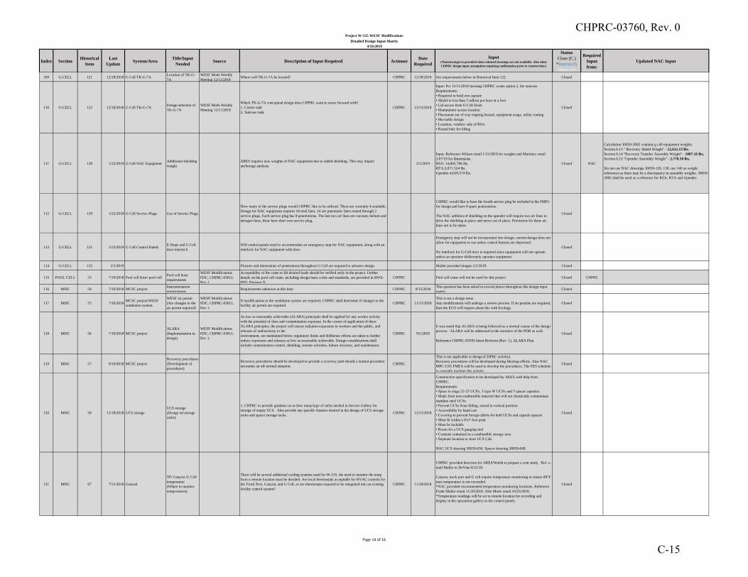
Index SectionHistorical
Item
Last
UpdateSystem/Area
Title/Input
NeededSource Description of Input Required Actionee
Date
Required
Input(*Interim input is provided when released drawings are not available. Also when
CHPRC design input assumption requiring confirmation prior to construction.)
Status
Close (C.)
*Interim (I)
Open (O)
Required
Input
from:
Updated NAC Input
Project W-135 WESF Modifications
Detailed Design Input Matrix
4/16/2019
109 G-CELL 121 12/18/2018 G Cell TK-G-7ALocation of TK-G-
7A
WESF Mods Weekly
Meeting 12/11/2018Where will TK-G-7A be located? CHPRC 12/30/2018 See requirements below in Historical Item 122. Closed
110 G-CELL 122 12/18/2018 G Cell TK-G-7ADesign selection of
TK-G-7A
WESF Mods Weekly
Meeting 12/11/2018
Which TK-G-7A conceptual design does CHPRC want to move forward with?
1. Corner tank
2. Suitcase tank
CHPRC 12/13/2018
Input: Per 12/11/2018 meeting CHPRC wants option 2, the suitcase.
Requirements:
• Required to hold one capsule
• Shield to less than 5 mRem per hour at a foot
• Lid access from G Cell Hoist
• Manipulator access location
• Placement out of way tripping hazard, equipment usage, utility routing
• Moveable design
• Location, window side of RSA
• Round bale for lifting
Closed
111 G-CELL 128 1/22/2019 G Cell NAC EquipmentAdditional shielding
weight
ARES requires new weights of NAC equipment due to added shielding. This may impact
anchorage analysis.2/1/2019
Input: Reference Wilson email 1/31/2019 for weights and Martinez email
2/07/19 for dimensions.
RSA: 14,843.796 lbs.
RTA:3,071.524 lbs.
Upender 4,010.574 lbs.
Closed NAC
Calculation 30059-2002 contains g cell equipment weights.
Section 6.13 " Recovery Shield Weight" - 12,612.13 lbs.
Section 6.14 "Recovery Transfer Assembly Weight" - 1007.16 lbs.
Section 6.15 "Upender Assembly Weight" - 2,778.50 lbs.
Do not use NAC drawings 30059-120, 130, nor 140 as weight
references as there may be a discrepancy in assembly weights. 30059-
2002 shall be used as a reference for RSA, RTA and Upender.
112 G-CELL 129 1/22/2019 G Cell Service Plugs Use of Service Plugs
How many of the service plugs would CHPRC like to be utilized. There are currently 4 available.
Design for NAC equipment requires 18 total lines. 16 are pneumatic lines routed through 2
service plugs. Each service plug has 8 penetrations. The last two air lines are vacuum, helium and
nitrogen lines, these have their own service plug.
CHPRC would like to have the fourth service plug be included in the FMP's
for design and have 8 spare penetrations.
The NAC addition of shielding on the upender will require two air lines to
drive the shielding in place and move out of place. Provisions for these air
lines are to be taken.
Closed
113 G-CELL 131 1/23/2019 G Cell Control PanelsE-Stops and G Cell
door interlock
Will control panels need to accommodate an emergency stop for NAC equipment, along with an
interlock for NAC equipment with door.
Emergency stop will not be incorporated into design, current design does not
allow for equipment to run unless control buttons are depressed.
No interlock for G-Cell door is required since equipment will not operate
unless an operator deliberately operates equipment.
Closed
114 G-CELL 133 2/5/2019 Pictures and dimensions of penetrations throughout G Cell are required to advance design. Muller provided images 2/5/2019. Closed
115 POOL CELL 53 7/10/2018 Pool cell hoist/ pool cellPool cell hoist
requirements
WESF Modifications
FDC, CHPRC-03011,
Rev 1,
Acceptability of the crane to lift desired loads should be verified early in the project. Further
details on the pool cell crane, including design basis codes and standards, are provided in HWS-
8951 Division X.
CHPRC Pool cell crane will not be used for this project. Closed CHPRC
116 MISC 54 7/10/2018 MCSC projectInstrumentation
requirements Requirements unknown at this time CHPRC 8/15/2018
This question has been asked in several places throughout this design input
matrixClosed
117 MISC 55 7/10/2018MCSC project/WESF
ventilation system
WESF air permit
(Are changes to the
air permit required)
WESF Modifications
FDC, CHPRC-03011,
Rev 1.
If modifications to the ventilation system are required, CHPRC shall determine if changes to the
facility air permit are required.CHPRC 11/15/2018
This is not a design issue.
Any modifications will undergo a review process. If air permits are required,
then the ECO will inquire about this with Ecology.
Closed
118 MISC 56 7/10/2018 MCSC project
ALARA
(Implementation in
design)
WESF Modifications
FDC, CHPRC-03011,
Rev 1.
As low as reasonably achievable (ALARA) principals shall be applied for any worker activity
with the potential of dose and contamination exposure. In the course of application of these
ALARA principles, the project will ensure radiation exposures to workers and the public, and
releases of radioactivity to the
environment, are maintained below regulatory limits and deliberate efforts are taken to further
reduce exposures and releases as low as reasonably achievable. Design considerations shall
include contamination control, shielding, remote activities, failure recovery, and maintenance.
CHPRC 9/1/2018
It was noted that ALARA is being followed as a normal course of the design
process. ALARA will be addressed in the narrative of the PDR as well.
Reference CHPRC-03593 latest Revision (Rev. 1), ALARA Plan.
Closed
119 MISC 57 9/10/2018 MCSC project
Recovery procedures
(Development of
procedures)
Recovery procedures should be developed to provide a recovery path should a normal procedure
encounter an off-normal situation.CHPRC
This is not applicable to design (CHPRC activity).
Recovery procedures will be developed during Mockup efforts. Also NAC
MPC-CSS FMEA will be used to develop the procedures. The FES schedule
is currently tracking this activity.
Closed
120 MISC 59 12/18/2018 UCS storage
UCS storage
(Design od storage
racks)
1. CHPRC to provide guidance as to how many/type of racks needed in Service Gallery for
storage of empty UCS. Also provide any specific features desired in the design of UCS storage
racks and spacer storage racks.CHPRC 12/13/2018
Construction specification to be developed by ARES with help from
CHPRC.
Requirements:
• Space to stage 22-25 UCS's, 5 type W UCS's and 5 spacer capsules.
• Made from non-combustible material that will not chemically contaminate
stainless steel UCSs
• Prevent UCSs from falling, stored in vertical position
• Accessibility by hand cart
• Covering to prevent foreign debris for both UCSs and capsule spacers
• Must fit within a 8'x3' foot print
• Must be lockable
• Room for a UCS gauging tool
• Contents contained in a combustible storage area
• Separate location to store UCS Lids
NAC UCS drawing 30059-050. Spacer drawing 30059-049.
Closed
121 MISC 67 7/31/2018 General
TP/ Canyon /G Cell
temperature
(Where to monitor
temperatures)
There will be several additional cooling systems used for W-135, the need to monitor the temp
from a remote location must be decided. Are local thermostats acceptable for HVAC controls for
the Truck Port, Canyon, and G Cell, or are thermostats required to be integrated into an existing
facility control system?
CHPRC 11/29/2018
CHPRC provided direction for ARES/Walsh to prepare a vent study. Ref. e-
mail Muller to DeVine 8/15/18.
Canyon, truck port and G cell require temperature monitoring to ensure 80°F
max temperature is not exceeded.
*NAC provided recommended temperature monitoring locations. Reference
Frank Muller email 11/20/2018. Also Marie email 10/25/2018.
*Temperature readings will be set to remote location for recording and
display in the operations gallery to the control panels.
Closed
Page 14 of 16
CHPRC-03760, Rev. 0
C-15

Index SectionHistorical
Item
Last
UpdateSystem/Area
Title/Input
NeededSource Description of Input Required Actionee
Date
Required
Input(*Interim input is provided when released drawings are not available. Also when
CHPRC design input assumption requiring confirmation prior to construction.)
Status
Close (C.)
*Interim (I)
Open (O)
Required
Input
from:
Updated NAC Input
Project W-135 WESF Modifications
Detailed Design Input Matrix
4/16/2019
122 MISC 73 8/24/2018
NAC Operations
(Equipment locations
and utility
requirements)
Determine equipment locations, control panel location, instrument air and gas line routing, and
conduit routing. See walk down meeting minutes, dated 8/17/18 (Letter 18RL098148). Closed
123 MISC 87 9/13/2018Compressed air for NAC
equipment
Process information
(Air pressures and
flows)
Brandon email 9/12/2018
ARES requires NAC equipment process information such as air flows and air pressures for NAC
equipment in order to size air piping diameter. Air flow and air pressure of the overall equipment
is required, but also the parts that make up the equipment are also necessary.
Example, UCS upender is a NAC equipment we know min 80, max 100 psig up to 10 SCFM
flowrate, but the Bimba cylinders that are part of the UCS upender have unknown air flows and
pressures.
CHPRC 12/13/2018
Bounding parameters were chosen for the cylinders by NAC. NAC will look
into lowering cfm. Need to discuss this topic more.
ARES currently developing proposed air pressures and line sizes, the results
will be presented and identified as being acceptable or not acceptable.
Closed NAC
DTS Grapple 10 CFM at 90 PSIG (FDR Interface Requirement)
SIA and G Cell cover block gate actuator bar lift cylinders 10 CFM
at 90 PSIG (FDR Interface Requirement)
UCS stabilizing (2), Test Cover Assembly In/Out (1), Test Cover
Assembly Raise/Lower (2) and Nutrunner Raise/Lower (1) all 10
CFM at 90 PSIG (FDR Interface Requirement)
TCA Seal 5 CFM at 90 PSIG (FDR Interface Requirement)
Nutrunner and RNutrunner 42 CFM at 100 PSIG (FDR Interface
Requirement)
For smaller components reference HiLine 1806-HEF-134-XX
drawings.
124 MISC 90 9/13/2018WESF/G-
Cell/Canyon/Truck port
NAC Operations
(Rad Dose Map)
30% WESF Mods
Presentation 9/4/2019ARES requires a rad dose map by NAC for best locations to place equipment. CHPRC 10/18/2018
30059-5007 has been provided.
10/26/2018, for general area inside of G Cell use 10^8 Total RAD.
For the upender use 10^9 Total RAD.
Closed NAC
For RSA Shielding Map reference 30059-5008.
For Upender Shielding Map reference 30059-5010
For VCC in Truckport Shielding Map reference 30059-5007
For DTS over G Cell and Truckport reference 30059-500 and 5007
125 MISC 91 9/13/2018 WESF HVAC HEPA filters30% WESF Mods
Presentation 9/4/2019Is there a need for HEPA filters in vacuum lines when pulling from rad to non-rad locations? CHPRC 10/18/2018
Input: No HEPA filtration required for any service air lines to NAC
equipment.
G Cell:
Vacuum and MSLD, along with exhaust as necessary, require TWO HEPA
filters in line vertically mounted.
The LB-5211 A-O filters are available in a variety of diameters; we want the
47-mm diameter filters (the thickness is 0.38 mm).
Canyon:
Vacuum pump requires HEPA filtration on the exhaust.
Closed CHPRC
126 MISC 95 9/13/2018 WESF HVAC
HVAC
(Power Outage
evaluation)
WESF Mods CDR SOW
R2 ATT3 Component
Number 6
1. CHPRC to provide guidance regarding ventilation system design requirements related to
protection against unanticipated outages.
(i) Truck Port
(ii) G Cell
(iii) Canyon
Notes:
(a) Basis ventilation and or cooling outage could occur as a result of maintenance or power
outages. W-135 should evaluate if system outage is acceptable for safety or planned outage.
(b) The results could cause ventilation or cooling to become important to safety, and possibly
require they be included with emergency power supply.
(c) A requirement to provide emergency power to either of these systems would invalidate an
Electrical Load assumption (LEMS-MCSC-17-CAL-006 rev 0, 3.0 A) No MCSC loads must be
connected to WESF emergency electrical power busses.
CHPRC 12/13/2018
1. Inputs:
(i) Truck Port: WESF Mods to provide redundant HVAC system with
backup power where feasible and practical. Components shall be AG-1
compliant or undergo CGD process. Design shall be in compliance with
DOE 420.1C. Three, ten ton outdoor heat pump units will be provided for
Truck Port and Canyon cooling. Two units are required the third is for
redundancy. Six wall-mounted heat exchanger units will be provided for
Truck Port cooling. Five are required one is for redundancy.
(ii) G Cell: WESF Mods to provide HVAC system with backup power
where feasible and practical. No redundancy. Components shall be AG-1
compliant or undergo CGD process. Design shall be in compliance with
DOE 420.1C.
(iii) Canyon: No additional measures required, unless redundancy in the
truckport cannot be separated from the canyon, then redundancy would need
to be incorporated as necessary.
See Tyler Crumpley email 12/20/2018 for redundancy discussion.
Action:
(i) CHPRC to work with ARES to assess if a solution short of 100%
redundancy would provide near equivalent protection.
Closed CHPRC
127 MISC 124 1/9/2019 WESF HVACCondensate Lines
Locations
12/18/2018 ARES
8:00AM meeting
WASLH requires location of condensate line inside of WESF truckport.
Also must ensure chiller condensate in G-Cell and Canyon are drained to the appropriate
locations.CHPRC 12/30/2018
Input:
Condensate drainage to TK-100 is not a viable option.
Condensate drainage to pool cell 9 or 10 is not a viable option.
Path forward based on 1/22/2019 walk down with WESF Operations and
Engineering is to provide space outside near the gas storage shed being
designed by ARES and have a heat trace on the lines to help with freezing.
Route condensate lines from within WESF through wall to the collection
tank. The tank(s) should be sized for 500 gallons with freeze protection.
Closed CHPRC
128 MISC 96 9/13/2018Geotechnical Report
RHO-R-25
Geotech report
(Provide feedback)
18RL08314 CHPRC W-
135 / WESF - DISCUSS
ARES APPROACH TO
STRUCTURAL
EVALUATIONS IN
SUPPORT OF W-135
WESF
MODIFICATIONS
PROJECT
CHPRC will review RHO-R-25 geotechnical report and provide ARES with any
feedback/comments/concerns.CHPRC 12/13/2018
Reference Martinez email 12/10/2018.
No comments or concerns where RHO-R-25 has been used by ARES.Closed
129 MISC 99 9/19/2018WESF/Outside Pad Near
Truck Port
Existing Vacuum
Pump Pad
(Can pad be cleared
of old equipment)
ARES 8:00AM weekly
meeting. 9/11/2018
Can vacuum pumps PAS-1 and PAS-2 be removed from existing pad outside of the truck port
area?CHPRC 10/4/2018
The vacuum pumps on the south side of WESF (PAS-1 & and PAS-2) have
been deactivated and shall be removed By W-135.Closed CHPRC
Page 15 of 16
CHPRC-03760, Rev. 0
C-16
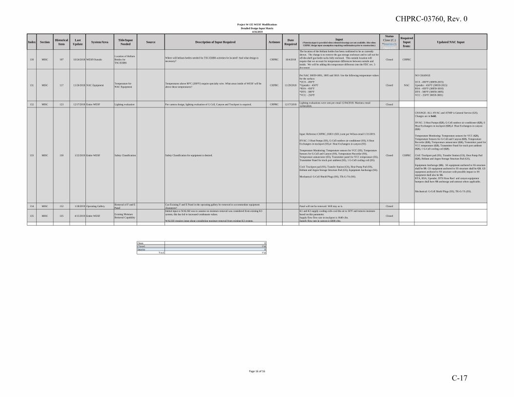
Index SectionHistorical
Item
Last
UpdateSystem/Area
Title/Input
NeededSource Description of Input Required Actionee
Date
Required
Input(*Interim input is provided when released drawings are not available. Also when
CHPRC design input assumption requiring confirmation prior to construction.)
Status
Close (C.)
*Interim (I)
Open (O)
Required
Input
from:
Updated NAC Input
Project W-135 WESF Modifications
Detailed Design Input Matrix
4/16/2019
130 MISC 107 10/24/2018 WESF/Outside
Location of Helium
Bottles for
TSC/EHBS
Where will helium bottles needed for TSC/EHBS activities be located? And what design is
necessary?CHPRC 10/4/2018
The location of the Helium bottles has been confirmed to be as currently
shown. The change is to remove the gas storage enclosure and to call out for
off-the-shelf gas bottle racks fully enclosed. This outside location will
require that we account for temperature differences between outside and
inside. We will be adding this temperature difference into the FDC rev. 3
document.
Closed CHPRC
131 MISC 117 11/26/2018 NAC EquipmentTemperature for
NAC Equipment
Temperatures above 90°C (200°F) require specialty wire. What areas inside of WESF will be
above these temperatures?CHPRC 11/29/2018
Per NAC 30059-3001, 3005 and 3010. Use the following temperature values
for the surface:
*UCS - 450°F
*Upender - 450°F
*RSA - 450°F
*DTS - 300°F
*VCC - 250°F
Closed NAC
NO CHANGE
UCS - 450°F (30059-2015)
Upender - 450°F (30059-2015)
RSA - 450°F (30059-3010)
DTS - 300°F (30059-3005)
VCC - 250°F 30059-3001)
132 MISC 123 12/17/2018 Entire WESF Lighting evaluation For camera design, lighting evaluation of G Cell, Canyon and Truckport is required. CHPRC 12/17/2018Lighting evaluations were sent per email 12/04/2018. Martinez email
12/04/2018.Closed
133 MISC 130 1/22/2019 Entire WESF Safety Classification Safety Classification for equipment is desired.
Input: Reference CHPRC_03831 (SEL) sent per Wilson email 1/31/2019.
HVAC: 3 Heat Pumps (SS), G-Cell outdoor air conditioner (SS), 6 Heat
Exchangers in truckport (SS),4 Heat Exchangers in canyon (SS)
Temperature Monitoring: Temperature sensors for VCC (SS), Temperature
Sensors for G-Cell and Canyon (SS), Temperature Recorder (SS),
Temperature annunciator (SS), Transmitter panel for VCC temperature (SS),
Transmitter Panel for truck port ambient (SS), 1 G-Cell cooling coil (SS).
Civil: Truckport pad (SS), Transfer Station (GS), Heat Pump Pad (SS),
Helium and Argon Storage Structure Pad (GS), Equipment Anchorage (SS).
Mechanical: G-Cell Shield Plugs (SS), TK-G-7A (SS).
Closed CHPRC
CHANGE: ALL HVAC and ATMP is General Service (GS).
Changes are in bold.
HVAC: 3 Heat Pumps (GS), G-Cell outdoor air conditioner (GS), 6
Heat Exchangers in truckport (GS),4 Heat Exchangers in canyon
(GS)
Temperature Monitoring: Temperature sensors for VCC (GS),
Temperature Sensors for G-Cell and Canyon (GS), Temperature
Recorder (GS), Temperature annunciator (GS), Transmitter panel for
VCC temperature (GS), Transmitter Panel for truck port ambient
(GS), 1 G-Cell cooling coil (GS).
Civil: Truckport pad (SS), Transfer Station (GS), Heat Pump Pad
(GS), Helium and Argon Storage Structure Pad (GS),
Equipment Anchorage (SS). SS equipment anchored to SS structure
shall be SS. GS equipment anchored to SS structure shall be GS. GS
equipment anchored to SS structure with possible impact to SS
equipment shall also be SS.
RTA, RSA, Upender, DTS Hose Reel and canyon equipment
bumpers shall have SS anchorage and unistrut where applicable.
Mechanical: G-Cell Shield Plugs (SS), TK-G-7A (SS).
134 MISC 132 1/28/2019 Operating GalleryRemoval of F and E
Panel
Can Existing F and E Panel in the operating gallery be removed to accommodate equipment
clearances?Panel will not be removed. Will stay as is. Closed
135 MISC 135 4/15/2019 Entire WESFExisting Moisture
Removal Capability
Initital input to WALSH was to assume no moisture removal was considered from existing K3
system, this has led to increased condensate values.
WALSH requires input about considering mositure removal from existing K3 system.
K1 and K3 supply cooling coils cool the air to 56°F and remove moisture
based on this parameter.
Supply flow flow rate in truckport is 1640 cfm.
Supply flow rate in canyon is 6000 cfm.
Closed
Open 0
Closed 134
Interim 0
Total 134
Page 16 of 16
CHPRC-03760, Rev. 0
C-17

CHPRC-03760, Rev. 0
D-1
APPENDIX D
AG-1 COMPLIANCE MATRIX
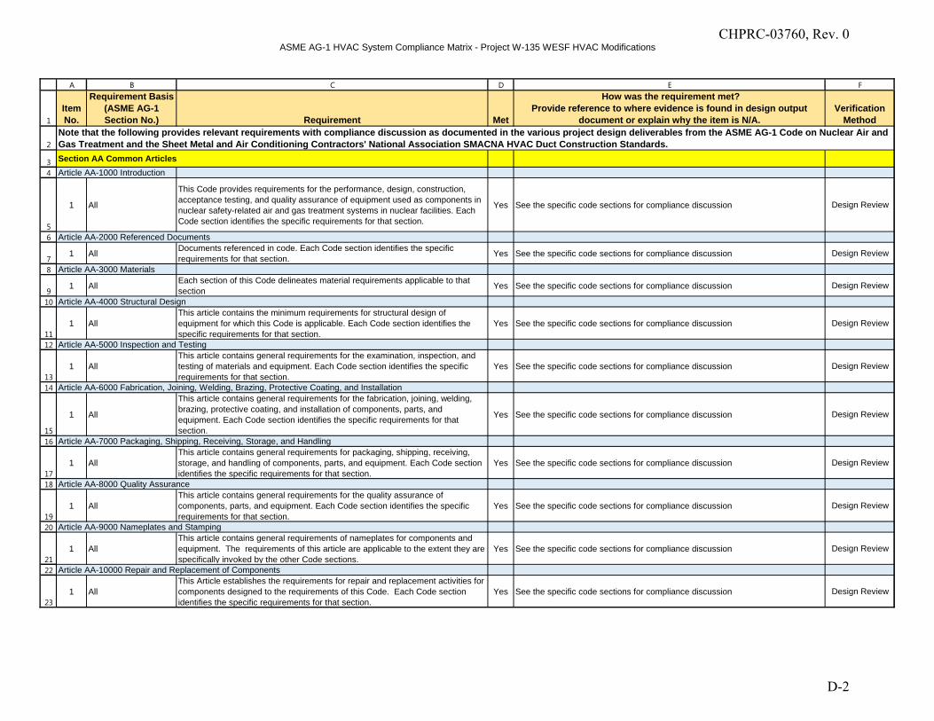
ASME AG-1 HVAC System Compliance Matrix - Project W-135 WESF HVAC Modifications
1
2
3
4
5
6
7
8
9
10
11
12
13
14
15
16
17
18
19
20
21
22
23
A B C D E F
Item No.
Requirement Basis (ASME AG-1 Section No.) Requirement Met
How was the requirement met?Provide reference to where evidence is found in design output
document or explain why the item is N/A.Verification
Method
Section AA Common ArticlesArticle AA-1000 Introduction
1 All
This Code provides requirements for the performance, design, construction, acceptance testing, and quality assurance of equipment used as components in nuclear safety-related air and gas treatment systems in nuclear facilities. Each Code section identifies the specific requirements for that section.
Yes See the specific code sections for compliance discussion Design Review
Article AA-2000 Referenced Documents
1 All Documents referenced in code. Each Code section identifies the specific requirements for that section. Yes See the specific code sections for compliance discussion Design Review
Article AA-3000 Materials
1 All Each section of this Code delineates material requirements applicable to that section Yes See the specific code sections for compliance discussion Design Review
Article AA-4000 Structural Design
1 AllThis article contains the minimum requirements for structural design of equipment for which this Code is applicable. Each Code section identifies the specific requirements for that section.
Yes See the specific code sections for compliance discussion Design Review
Article AA-5000 Inspection and Testing
1 AllThis article contains general requirements for the examination, inspection, and testing of materials and equipment. Each Code section identifies the specific requirements for that section.
Yes See the specific code sections for compliance discussion Design Review
Article AA-6000 Fabrication, Joining, Welding, Brazing, Protective Coating, and Installation
1 All
This article contains general requirements for the fabrication, joining, welding, brazing, protective coating, and installation of components, parts, and equipment. Each Code section identifies the specific requirements for that section.
Yes See the specific code sections for compliance discussion Design Review
Article AA-7000 Packaging, Shipping, Receiving, Storage, and Handling
1 AllThis article contains general requirements for packaging, shipping, receiving, storage, and handling of components, parts, and equipment. Each Code section identifies the specific requirements for that section.
Yes See the specific code sections for compliance discussion Design Review
Article AA-8000 Quality Assurance
1 AllThis article contains general requirements for the quality assurance of components, parts, and equipment. Each Code section identifies the specific requirements for that section.
Yes See the specific code sections for compliance discussion Design Review
Article AA-9000 Nameplates and Stamping
1 AllThis article contains general requirements of nameplates for components and equipment. The requirements of this article are applicable to the extent they are specifically invoked by the other Code sections.
Yes See the specific code sections for compliance discussion Design Review
Article AA-10000 Repair and Replacement of Components
1 AllThis Article establishes the requirements for repair and replacement activities for components designed to the requirements of this Code. Each Code section identifies the specific requirements for that section.
Yes See the specific code sections for compliance discussion Design Review
Note that the following provides relevant requirements with compliance discussion as documented in the various project design deliverables from the ASME AG-1 Code on Nuclear Air and Gas Treatment and the Sheet Metal and Air Conditioning Contractors' National Association SMACNA HVAC Duct Construction Standards.
CHPRC-03760, Rev. 0
D-2
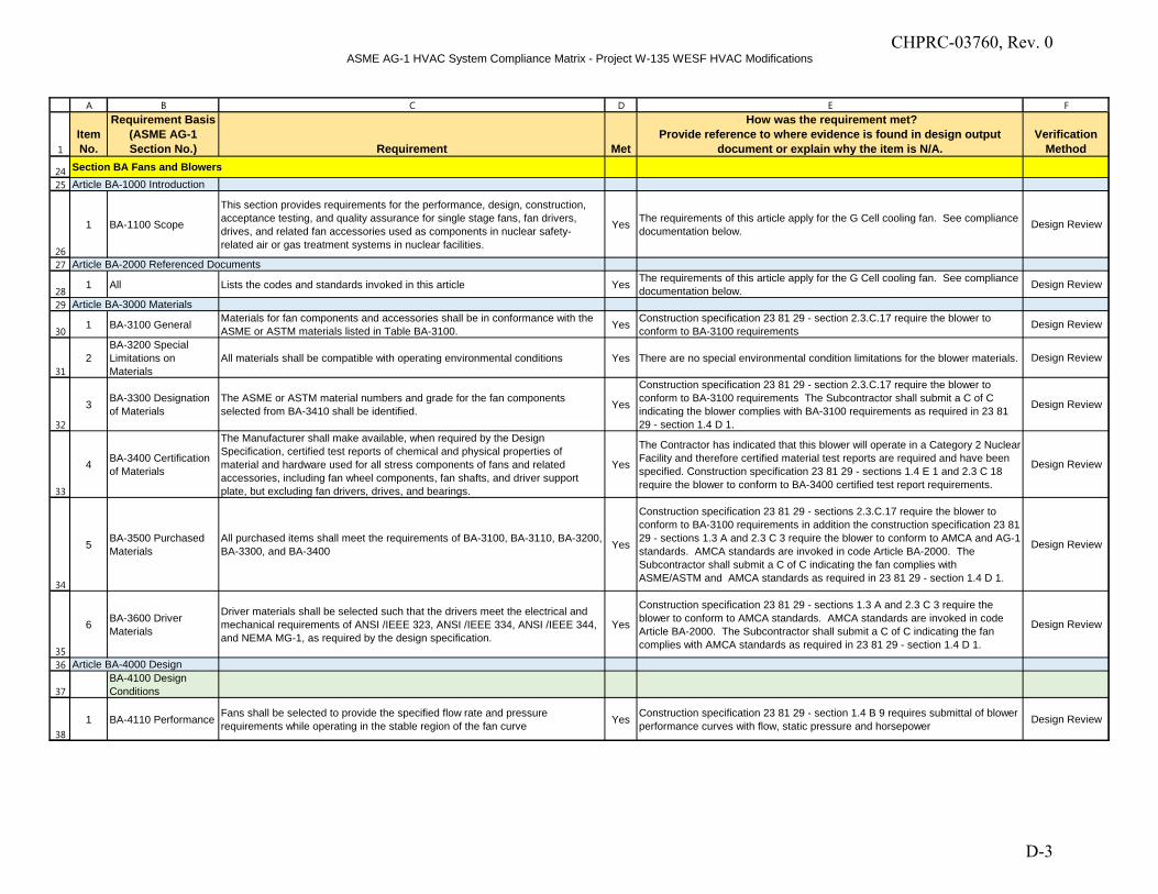
ASME AG-1 HVAC System Compliance Matrix - Project W-135 WESF HVAC Modifications
1
A B C D E F
Item No.
Requirement Basis (ASME AG-1 Section No.) Requirement Met
How was the requirement met?Provide reference to where evidence is found in design output
document or explain why the item is N/A.Verification
Method
24
25
26
27
28
29
30
31
32
33
34
35
36
37
38
Section BA Fans and BlowersArticle BA-1000 Introduction
1 BA-1100 Scope
This section provides requirements for the performance, design, construction, acceptance testing, and quality assurance for single stage fans, fan drivers, drives, and related fan accessories used as components in nuclear safety-related air or gas treatment systems in nuclear facilities.
Yes The requirements of this article apply for the G Cell cooling fan. See compliance documentation below.
Design Review
Article BA-2000 Referenced Documents
1 All Lists the codes and standards invoked in this article Yes The requirements of this article apply for the G Cell cooling fan. See compliance documentation below. Design Review
Article BA-3000 Materials
1 BA-3100 General Materials for fan components and accessories shall be in conformance with the ASME or ASTM materials listed in Table BA-3100. Yes Construction specification 23 81 29 - section 2.3.C.17 require the blower to
conform to BA-3100 requirements Design Review
2BA-3200 Special Limitations on Materials
All materials shall be compatible with operating environmental conditions Yes There are no special environmental condition limitations for the blower materials. Design Review
3 BA-3300 Designation of Materials
The ASME or ASTM material numbers and grade for the fan components selected from BA-3410 shall be identified. Yes
Construction specification 23 81 29 - section 2.3.C.17 require the blower to conform to BA-3100 requirements The Subcontractor shall submit a C of C indicating the blower complies with BA-3100 requirements as required in 23 81 29 - section 1.4 D 1.
Design Review
4 BA-3400 Certification of Materials
The Manufacturer shall make available, when required by the Design Specification, certified test reports of chemical and physical properties of material and hardware used for all stress components of fans and related accessories, including fan wheel components, fan shafts, and driver support plate, but excluding fan drivers, drives, and bearings.
Yes
The Contractor has indicated that this blower will operate in a Category 2 Nuclear Facility and therefore certified material test reports are required and have been specified. Construction specification 23 81 29 - sections 1.4 E 1 and 2.3 C 18 require the blower to conform to BA-3400 certified test report requirements.
Design Review
5 BA-3500 Purchased Materials
All purchased items shall meet the requirements of BA-3100, BA-3110, BA-3200, BA-3300, and BA-3400 Yes
Construction specification 23 81 29 - sections 2.3.C.17 require the blower to conform to BA-3100 requirements in addition the construction specification 23 81 29 - sections 1.3 A and 2.3 C 3 require the blower to conform to AMCA and AG-1 standards. AMCA standards are invoked in code Article BA-2000. The Subcontractor shall submit a C of C indicating the fan complies with ASME/ASTM and AMCA standards as required in 23 81 29 - section 1.4 D 1.
Design Review
6 BA-3600 Driver Materials
Driver materials shall be selected such that the drivers meet the electrical and mechanical requirements of ANSI /IEEE 323, ANSI /IEEE 334, ANSI /IEEE 344, and NEMA MG-1, as required by the design specification.
Yes
Construction specification 23 81 29 - sections 1.3 A and 2.3 C 3 require the blower to conform to AMCA standards. AMCA standards are invoked in code Article BA-2000. The Subcontractor shall submit a C of C indicating the fan complies with AMCA standards as required in 23 81 29 - section 1.4 D 1.
Design Review
Article BA-4000 DesignBA-4100 Design Conditions
1 BA-4110 Performance Fans shall be selected to provide the specified flow rate and pressure requirements while operating in the stable region of the fan curve Yes Construction specification 23 81 29 - section 1.4 B 9 requires submittal of blower
performance curves with flow, static pressure and horsepower Design Review
CHPRC-03760, Rev. 0
D-3
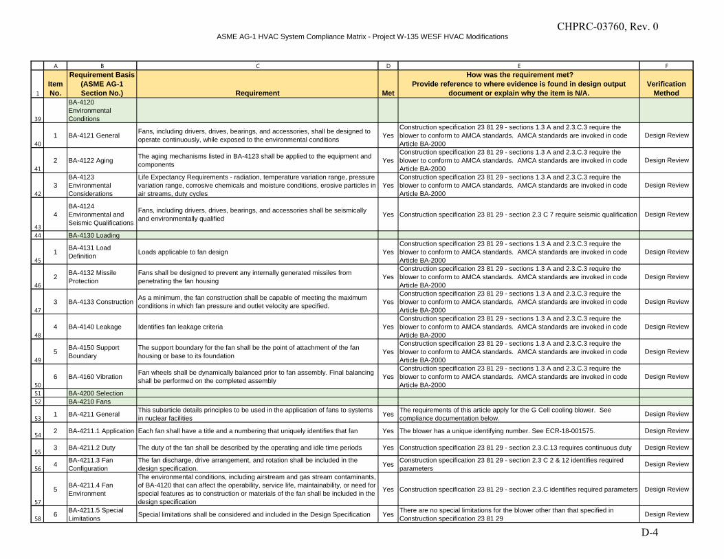
ASME AG-1 HVAC System Compliance Matrix - Project W-135 WESF HVAC Modifications
1
A B C D E F
Item No.
Requirement Basis (ASME AG-1 Section No.) Requirement Met
How was the requirement met?Provide reference to where evidence is found in design output
document or explain why the item is N/A.Verification
Method
39
40
41
42
43
44
45
46
47
48
49
50
51
52
53
54
55
56
57
58
BA-4120 Environmental Conditions
1 BA-4121 General Fans, including drivers, drives, bearings, and accessories, shall be designed to operate continuously, while exposed to the environmental conditions Yes
Construction specification 23 81 29 - sections 1.3 A and 2.3.C.3 require the blower to conform to AMCA standards. AMCA standards are invoked in code Article BA-2000
Design Review
2 BA-4122 Aging The aging mechanisms listed in BA-4123 shall be applied to the equipment and components Yes
Construction specification 23 81 29 - sections 1.3 A and 2.3.C.3 require the blower to conform to AMCA standards. AMCA standards are invoked in code Article BA-2000
Design Review
3BA-4123 Environmental Considerations
Life Expectancy Requirements - radiation, temperature variation range, pressure variation range, corrosive chemicals and moisture conditions, erosive particles in air streams, duty cycles
YesConstruction specification 23 81 29 - sections 1.3 A and 2.3.C.3 require the blower to conform to AMCA standards. AMCA standards are invoked in code Article BA-2000
Design Review
4BA-4124 Environmental and Seismic Qualifications
Fans, including drivers, drives, bearings, and accessories shall be seismically and environmentally qualified Yes Construction specification 23 81 29 - section 2.3 C 7 require seismic qualification Design Review
BA-4130 Loading
1 BA-4131 Load Definition Loads applicable to fan design Yes
Construction specification 23 81 29 - sections 1.3 A and 2.3.C.3 require the blower to conform to AMCA standards. AMCA standards are invoked in code Article BA-2000
Design Review
2 BA-4132 Missile Protection
Fans shall be designed to prevent any internally generated missiles from penetrating the fan housing Yes
Construction specification 23 81 29 - sections 1.3 A and 2.3.C.3 require the blower to conform to AMCA standards. AMCA standards are invoked in code Article BA-2000
Design Review
3 BA-4133 Construction As a minimum, the fan construction shall be capable of meeting the maximum conditions in which fan pressure and outlet velocity are specified. Yes
Construction specification 23 81 29 - sections 1.3 A and 2.3.C.3 require the blower to conform to AMCA standards. AMCA standards are invoked in code Article BA-2000
Design Review
4 BA-4140 Leakage Identifies fan leakage criteria YesConstruction specification 23 81 29 - sections 1.3 A and 2.3.C.3 require the blower to conform to AMCA standards. AMCA standards are invoked in code Article BA-2000
Design Review
5 BA-4150 Support Boundary
The support boundary for the fan shall be the point of attachment of the fan housing or base to its foundation Yes
Construction specification 23 81 29 - sections 1.3 A and 2.3.C.3 require the blower to conform to AMCA standards. AMCA standards are invoked in code Article BA-2000
Design Review
6 BA-4160 Vibration Fan wheels shall be dynamically balanced prior to fan assembly. Final balancing shall be performed on the completed assembly Yes
Construction specification 23 81 29 - sections 1.3 A and 2.3.C.3 require the blower to conform to AMCA standards. AMCA standards are invoked in code Article BA-2000
Design Review
BA-4200 SelectionBA-4210 Fans
1 BA-4211 General This subarticle details principles to be used in the application of fans to systems in nuclear facilities Yes The requirements of this article apply for the G Cell cooling blower. See
compliance documentation below. Design Review
2 BA-4211.1 Application Each fan shall have a title and a numbering that uniquely identifies that fan Yes The blower has a unique identifying number. See ECR-18-001575. Design Review
3 BA-4211.2 Duty The duty of the fan shall be described by the operating and idle time periods Yes Construction specification 23 81 29 - section 2.3.C.13 requires continuous duty Design Review
4 BA-4211.3 Fan Configuration
The fan discharge, drive arrangement, and rotation shall be included in the design specification. Yes Construction specification 23 81 29 - section 2.3 C 2 & 12 identifies required
parameters Design Review
5 BA-4211.4 Fan Environment
The environmental conditions, including airstream and gas stream contaminants, of BA-4120 that can affect the operability, service life, maintainability, or need for special features as to construction or materials of the fan shall be included in the design specification
Yes Construction specification 23 81 29 - section 2.3.C identifies required parameters Design Review
6 BA-4211.5 Special Limitations Special limitations shall be considered and included in the Design Specification Yes There are no special limitations for the blower other than that specified in
Construction specification 23 81 29 Design Review
CHPRC-03760, Rev. 0
D-4
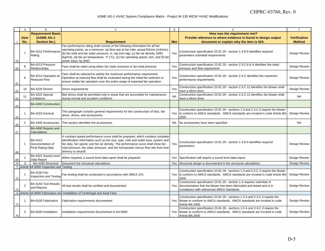
ASME AG-1 HVAC System Compliance Matrix - Project W-135 WESF HVAC Modifications
1
A B C D E F
Item No.
Requirement Basis (ASME AG-1 Section No.) Requirement Met
How was the requirement met?Provide reference to where evidence is found in design output
document or explain why the item is N/A.Verification
Method
59
60
61
62
63
64
65
66
67
68
69
70
71
72
73
74
75
76
7 BA-4212 Performance Rating
Fan performance rating shall consist of the following information for all fan operating points, as a minimum: (a) flow rate at fan inlet, actual ft3/min (m3/min), (b) fan total and fan static pressure, in. wg (mm wg), (c) fan air density, lb/ft3 (kg/m3), (d) fan air temperature, °F (°C), (e) fan operating speed, rpm, and (f) fan power input, hp (kW)
Yes Construction specification 23 81 29 - section 1.4 B 9 identifies required parameters submittal requirements
Design Review
8 BA-4213 Pressure Relationships Fans shall be rated using either fan static pressure or fan total pressure Yes Construction specification 23 81 29 - section 2.3.C.8 & 9 identifies the static
pressure and flow requirement Design Review
9 BA-4214 Operation at Reduced Flow
Fans shall be selected to satisfy the maximum performance requirement. Operation at reduced flow shall be evaluated during the initial fan selection to ensure stable fan operation over the entire range of expected fan operation
Yes Construction specification 23 81 29 - section 2.3.C identifies the maximum performance requirements. Design Review
10 BA-4220 Drivers Driver requirements Yes Construction specification 23 81 29 - section 2.3.C.12 identifies the blower shall have a direct drive Design Review
11 BA-4222 Special Limitations
Belt drives shall be permitted only in areas that are accessible for maintenance during normal and accident conditions NA Construction specification 23 81 29 - section 2.3.C.12 identifies the blower shall
have a direct drive NA
BA-4300 Construction
1 BA-4310 General This paragraph contains general requirements for the construction of fans, fan driver, drives, and accessories Yes
Construction specification 23 81 29 - sections 1.3 and 2.3.C.3 require the blower to conform to AMCA standards. AMCA standards are invoked in code Article BA-2000
Design Review
2 BA-4340 Accessories This section identifies the accessories NA No accessories have been specified NA
BA-4400 Reports and Calculations
1BA-4412 Documentation of Final Rating Data
A constant-speed performance curve shall be prepared, which contains complete identification information such as fan size, type, inlet and outlet area, system and fan duty, fan speed, and fan air density. The performance curve shall show fan total pressure, fan static pressure, and fan horsepower versus flow rate from free delivery to shutoff.
Yes Construction specification 23 81 29 - section 1.4 B 9 identifies required parameters
Design Review
2 BA-4421 Sound Level Data Report When required, a sound level data report shall be prepared Yes Specification will require a sound level data report. Design Review
3 BA-4430 Structural Document the structural calculations Yes Structural design is documented in the structural calculations Design ReviewArticle BA-5000 Inspection and Testing
1 BA-5100 Fan Inspection and Testing Fan testing shall be conducted in accordance with AMCA 210. Yes
Construction specification 23 81 29 - sections 1.3 and 2.3.C.3 require the blower to conform to AMCA standards. AMCA standards are invoked in code Article BA-2000
Design Review
2 BA-5150 Test Results and Reports All test results shall be certified and documented Yes
Construction specification 23 81 29 - section 1.4 requires submittal of documentation that the blower has been fabricated and tested and is in compliance with referenced AMCA Standards
Design Review
Article BA-6000 Fabrication and Installation of Centrifugal and Axial Fans
1 BA-6100 Fabrication Fabrication requirements documented YesConstruction specification 23 81 29 - sections 1.3 A and 2.3.C.3 require the blower to conform to AMCA standards. AMCA standards are invoked in code Article BA-2000
Design Review
2 BA-6200 Installation Installation requirements documented in AA-6600 YesConstruction specification 23 81 29 - sections 1.3 A and 2.3.C.3 require the blower to conform to AMCA standards. AMCA standards are invoked in code Article BA-2000
Design Review
CHPRC-03760, Rev. 0
D-5
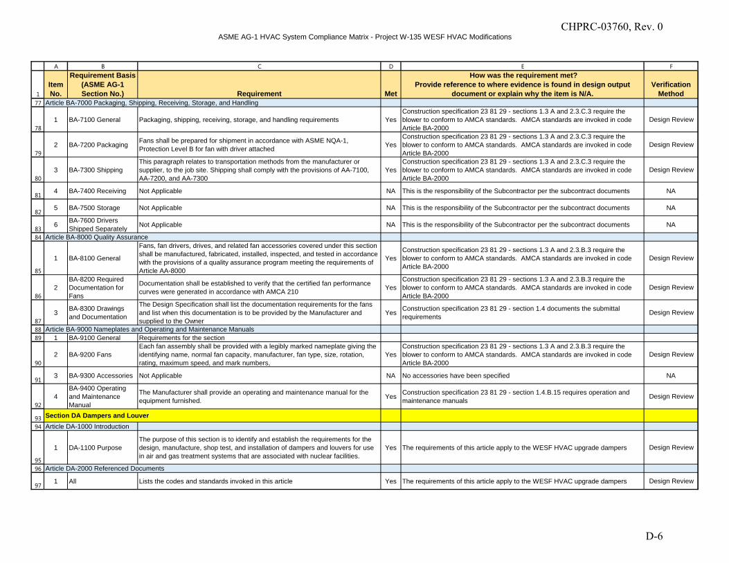
ASME AG-1 HVAC System Compliance Matrix - Project W-135 WESF HVAC Modifications
1
A B C D E F
Item No.
Requirement Basis (ASME AG-1 Section No.) Requirement Met
How was the requirement met?Provide reference to where evidence is found in design output
document or explain why the item is N/A.Verification
Method77
78
79
80
81
82
83
84
85
86
87
88
89
90
91
92
93
94
95
96
97
Article BA-7000 Packaging, Shipping, Receiving, Storage, and Handling
1 BA-7100 General Packaging, shipping, receiving, storage, and handling requirements YesConstruction specification 23 81 29 - sections 1.3 A and 2.3.C.3 require the blower to conform to AMCA standards. AMCA standards are invoked in code Article BA-2000
Design Review
2 BA-7200 Packaging Fans shall be prepared for shipment in accordance with ASME NQA-1, Protection Level B for fan with driver attached Yes
Construction specification 23 81 29 - sections 1.3 A and 2.3.C.3 require the blower to conform to AMCA standards. AMCA standards are invoked in code Article BA-2000
Design Review
3 BA-7300 ShippingThis paragraph relates to transportation methods from the manufacturer or supplier, to the job site. Shipping shall comply with the provisions of AA-7100, AA-7200, and AA-7300
YesConstruction specification 23 81 29 - sections 1.3 A and 2.3.C.3 require the blower to conform to AMCA standards. AMCA standards are invoked in code Article BA-2000
Design Review
4 BA-7400 Receiving Not Applicable NA This is the responsibility of the Subcontractor per the subcontract documents NA
5 BA-7500 Storage Not Applicable NA This is the responsibility of the Subcontractor per the subcontract documents NA
6 BA-7600 Drivers Shipped Separately Not Applicable NA This is the responsibility of the Subcontractor per the subcontract documents NA
Article BA-8000 Quality Assurance
1 BA-8100 General
Fans, fan drivers, drives, and related fan accessories covered under this section shall be manufactured, fabricated, installed, inspected, and tested in accordance with the provisions of a quality assurance program meeting the requirements of Article AA-8000
YesConstruction specification 23 81 29 - sections 1.3 A and 2.3.B.3 require the blower to conform to AMCA standards. AMCA standards are invoked in code Article BA-2000
Design Review
2BA-8200 Required Documentation for Fans
Documentation shall be established to verify that the certified fan performance curves were generated in accordance with AMCA 210 Yes
Construction specification 23 81 29 - sections 1.3 A and 2.3.B.3 require the blower to conform to AMCA standards. AMCA standards are invoked in code Article BA-2000
Design Review
3 BA-8300 Drawings and Documentation
The Design Specification shall list the documentation requirements for the fans and list when this documentation is to be provided by the Manufacturer and supplied to the Owner
Yes Construction specification 23 81 29 - section 1.4 documents the submittal requirements Design Review
Article BA-9000 Nameplates and Operating and Maintenance Manuals 1 BA-9100 General Requirements for the section
2 BA-9200 Fans Each fan assembly shall be provided with a legibly marked nameplate giving the identifying name, normal fan capacity, manufacturer, fan type, size, rotation, rating, maximum speed, and mark numbers,
YesConstruction specification 23 81 29 - sections 1.3 A and 2.3.B.3 require the blower to conform to AMCA standards. AMCA standards are invoked in code Article BA-2000
Design Review
3 BA-9300 Accessories Not Applicable NA No accessories have been specified NA
4BA-9400 Operating and Maintenance Manual
The Manufacturer shall provide an operating and maintenance manual for the equipment furnished. Yes Construction specification 23 81 29 - section 1.4.B.15 requires operation and
maintenance manuals Design Review
Section DA Dampers and LouverArticle DA-1000 Introduction
1 DA-1100 PurposeThe purpose of this section is to identify and establish the requirements for the design, manufacture, shop test, and installation of dampers and louvers for use in air and gas treatment systems that are associated with nuclear facilities.
Yes The requirements of this article apply to the WESF HVAC upgrade dampers Design Review
Article DA-2000 Referenced Documents
1 All Lists the codes and standards invoked in this article Yes The requirements of this article apply to the WESF HVAC upgrade dampers Design Review
CHPRC-03760, Rev. 0
D-6
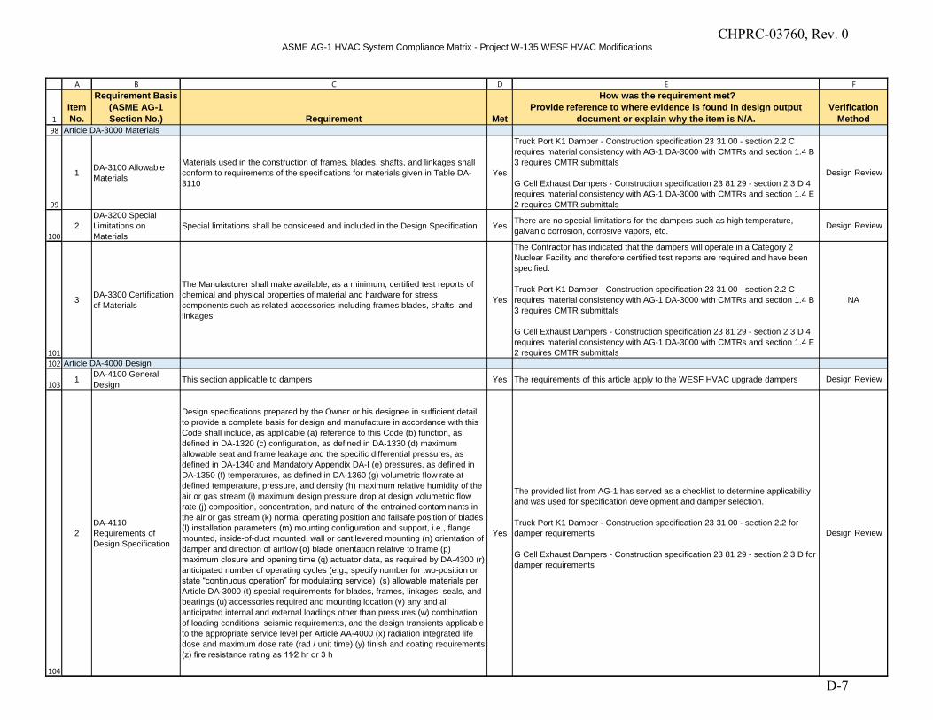
ASME AG-1 HVAC System Compliance Matrix - Project W-135 WESF HVAC Modifications
1
A B C D E F
Item No.
Requirement Basis (ASME AG-1 Section No.) Requirement Met
How was the requirement met?Provide reference to where evidence is found in design output
document or explain why the item is N/A.Verification
Method98
99
100
101
102
103
104
Article DA-3000 Materials
1 DA-3100 Allowable Materials
Materials used in the construction of frames, blades, shafts, and linkages shall conform to requirements of the specifications for materials given in Table DA-3110
Yes
Truck Port K1 Damper - Construction specification 23 31 00 - section 2.2 C requires material consistency with AG-1 DA-3000 with CMTRs and section 1.4 B 3 requires CMTR submittals
G Cell Exhaust Dampers - Construction specification 23 81 29 - section 2.3 D 4 requires material consistency with AG-1 DA-3000 with CMTRs and section 1.4 E 2 requires CMTR submittals
Design Review
2DA-3200 Special Limitations on Materials
Special limitations shall be considered and included in the Design Specification Yes There are no special limitations for the dampers such as high temperature, galvanic corrosion, corrosive vapors, etc. Design Review
3 DA-3300 Certification of Materials
The Manufacturer shall make available, as a minimum, certified test reports of chemical and physical properties of material and hardware for stress components such as related accessories including frames blades, shafts, and linkages.
Yes
The Contractor has indicated that the dampers will operate in a Category 2 Nuclear Facility and therefore certified test reports are required and have been specified.
Truck Port K1 Damper - Construction specification 23 31 00 - section 2.2 C requires material consistency with AG-1 DA-3000 with CMTRs and section 1.4 B 3 requires CMTR submittals
G Cell Exhaust Dampers - Construction specification 23 81 29 - section 2.3 D 4 requires material consistency with AG-1 DA-3000 with CMTRs and section 1.4 E 2 requires CMTR submittals
NA
Article DA-4000 Design
1 DA-4100 General Design This section applicable to dampers Yes The requirements of this article apply to the WESF HVAC upgrade dampers Design Review
2DA-4110 Requirements of Design Specification
Design specifications prepared by the Owner or his designee in sufficient detail to provide a complete basis for design and manufacture in accordance with this Code shall include, as applicable (a) reference to this Code (b) function, as defined in DA-1320 (c) configuration, as defined in DA-1330 (d) maximum allowable seat and frame leakage and the specific differential pressures, as defined in DA-1340 and Mandatory Appendix DA-I (e) pressures, as defined in DA-1350 (f) temperatures, as defined in DA-1360 (g) volumetric flow rate at defined temperature, pressure, and density (h) maximum relative humidity of the air or gas stream (i) maximum design pressure drop at design volumetric flow rate (j) composition, concentration, and nature of the entrained contaminants in the air or gas stream (k) normal operating position and failsafe position of blades (l) installation parameters (m) mounting configuration and support, i.e., flange mounted, inside-of-duct mounted, wall or cantilevered mounting (n) orientation of damper and direction of airflow (o) blade orientation relative to frame (p) maximum closure and opening time (q) actuator data, as required by DA-4300 (r) anticipated number of operating cycles (e.g., specify number for two-position or state “continuous operation” for modulating service) (s) allowable materials per
Article DA-3000 (t) special requirements for blades, frames, linkages, seals, and bearings (u) accessories required and mounting location (v) any and all anticipated internal and external loadings other than pressures (w) combination of loading conditions, seismic requirements, and the design transients applicable to the appropriate service level per Article AA-4000 (x) radiation integrated life dose and maximum dose rate (rad / unit time) (y) finish and coating requirements (z) fire resistance rating as 11⁄2 hr or 3 h
Yes
The provided list from AG-1 has served as a checklist to determine applicability and was used for specification development and damper selection.
Truck Port K1 Damper - Construction specification 23 31 00 - section 2.2 for damper requirements G Cell Exhaust Dampers - Construction specification 23 81 29 - section 2.3 D for damper requirements
Design Review
CHPRC-03760, Rev. 0
D-7
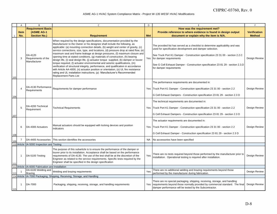
ASME AG-1 HVAC System Compliance Matrix - Project W-135 WESF HVAC Modifications
1
A B C D E F
Item No.
Requirement Basis (ASME AG-1 Section No.) Requirement Met
How was the requirement met?Provide reference to where evidence is found in design output
document or explain why the item is N/A.Verification
Method
105
106
107
108
109
110
111
112
113
114
115
3DA-4120 Requirements of the Manufacturer
When required by the design specifications, documentation provided by the Manufacturer to the Owner or his designee shall include the following, as applicable: (a) mounting connection details, (b) weight and center of gravity, (c) service connections, size, type, and locations, (d) pressure drop at rated flow, (e) maximum seat and frame leakage at design pressures, (f) maximum closure and opening time at stated conditions, (g) materials of construction, (h) bearing design life, (i) seal design life, (j) actuator torque supplied, (k) damper or louver torque required, (l) actuator environmental and seismic qualifications, (m) verification of structural integrity, performance, and qualification in accordance with Article AA-4000, (n) actuator position or orientation, (o) UL fire resistance rating and UL installation instructions, (p) Manufacturer’s Recommended
Replacement Parts List
Yes
The provided list has served as a checklist to determine applicability and was used for specification development and damper selection.
See Truck Port K1 Damper - Construction specification 23 31 00 - section 2.2.C for damper requirements
See G Cell Exhaust Damper - Construction specification 23 81 29 - section 2.3.D for damper requirements
Design Review
4 DA-4130 Performance Requirements Requirements for damper performance Yes
The performance requirements are documented in:
Truck Port K1 Damper - Construction specification 23 31 00 - section 2.2
G Cell Exhaust Dampers - Construction specification 23 81 29 - section 2.3 D
Design Review
5 DA-4200 Technical Requirement Technical Requirements Yes
The technical requirements are documented in:
Truck Port K1 Damper - Construction specification 23 31 00 - section 2.2
G Cell Exhaust Dampers - Construction specification 23 81 29 - section 2.3 D
Design Review
6 DA-4300 Actuators Manual actuators should be equipped with locking devices and position indicators Yes
The actuator requirements are documented in:
Truck Port K1 Damper - Construction specification 23 31 00 - section 2.2 G Cell Exhaust Damper - Construction specification 23 81 29 - section 2.3 D
Design Review
7 DA-4400 Accessories This section identifies the accessories NA No accessories have been specified
Article DA-5000 Inspection and Testing
1 DA-5100 Testing
The purpose of this subarticle is to ensure the performance of the damper or louver prior to its installation. Acceptance shall be based on the performance requirements of DA-4130. The use of the test shall be at the discretion of the Engineer as related to the service requirements. Specific tests required by the Engineer shall be specified in the design specification
Yes There are no tests required beyond those performed by the manufacturer prior to installation. Operational testing is required after installation. Design Review
Article DA-6000 Fabrication and Installation
1 DA-6100 Welding and Brazing Welding and brazing requirements Yes There are no additional welding and brazing requirements beyond those
performed by the manufacturer during fabrication. Design Review
Article DA-7000 Packaging, Shipping, Receiving, Storage, and Handling
1 DA-7000 Packaging, shipping, receiving, storage, and handling requirements YesThere are no special packaging, shipping, receiving, storage, and handling requirements beyond those normally provided by commercial standard. The final damper performance will be tested by the Subcontractor.
Design Review
CHPRC-03760, Rev. 0
D-8
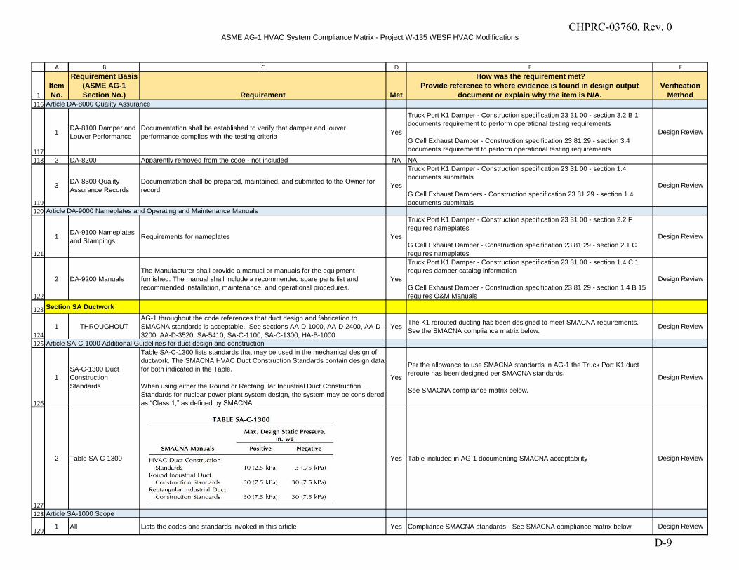
ASME AG-1 HVAC System Compliance Matrix - Project W-135 WESF HVAC Modifications
1
A B C D E F
Item No.
Requirement Basis (ASME AG-1 Section No.) Requirement Met
How was the requirement met?Provide reference to where evidence is found in design output
document or explain why the item is N/A.Verification
Method116
117
118
119
120
121
122
123
124
125
126
127
128
129
Article DA-8000 Quality Assurance
1 DA-8100 Damper and Louver Performance
Documentation shall be established to verify that damper and louver performance complies with the testing criteria Yes
Truck Port K1 Damper - Construction specification 23 31 00 - section 3.2 B 1 documents requirement to perform operational testing requirements
G Cell Exhaust Damper - Construction specification 23 81 29 - section 3.4 documents requirement to perform operational testing requirements
Design Review
2 DA-8200 Apparently removed from the code - not included NA NA
3 DA-8300 Quality Assurance Records
Documentation shall be prepared, maintained, and submitted to the Owner for record Yes
Truck Port K1 Damper - Construction specification 23 31 00 - section 1.4 documents submittals
G Cell Exhaust Dampers - Construction specification 23 81 29 - section 1.4 documents submittals
Design Review
Article DA-9000 Nameplates and Operating and Maintenance Manuals
1 DA-9100 Nameplates and Stampings Requirements for nameplates Yes
Truck Port K1 Damper - Construction specification 23 31 00 - section 2.2 F requires nameplates
G Cell Exhaust Damper - Construction specification 23 81 29 - section 2.1 C requires nameplates
Design Review
2 DA-9200 ManualsThe Manufacturer shall provide a manual or manuals for the equipment furnished. The manual shall include a recommended spare parts list and recommended installation, maintenance, and operational procedures.
Yes
Truck Port K1 Damper - Construction specification 23 31 00 - section 1.4 C 1 requires damper catalog information
G Cell Exhaust Damper - Construction specification 23 81 29 - section 1.4 B 15 requires O&M Manuals
Design Review
Section SA Ductwork
1 THROUGHOUTAG-1 throughout the code references that duct design and fabrication to SMACNA standards is acceptable. See sections AA-D-1000, AA-D-2400, AA-D-3200, AA-D-3520, SA-5410, SA-C-1100, SA-C-1300, HA-B-1000
Yes The K1 rerouted ducting has been designed to meet SMACNA requirements. See the SMACNA compliance matrix below. Design Review
Article SA-C-1000 Additional Guidelines for duct design and construction
1SA-C-1300 Duct Construction Standards
Table SA-C-1300 lists standards that may be used in the mechanical design of ductwork. The SMACNA HVAC Duct Construction Standards contain design data for both indicated in the Table.
When using either the Round or Rectangular Industrial Duct Construction Standards for nuclear power plant system design, the system may be considered as “Class 1,” as defined by SMACNA.
Yes
Per the allowance to use SMACNA standards in AG-1 the Truck Port K1 duct reroute has been designed per SMACNA standards.
See SMACNA compliance matrix below.
Design Review
2 Table SA-C-1300 Yes Table included in AG-1 documenting SMACNA acceptability Design Review
Article SA-1000 Scope
1 All Lists the codes and standards invoked in this article Yes Compliance SMACNA standards - See SMACNA compliance matrix below Design Review
CHPRC-03760, Rev. 0
D-9
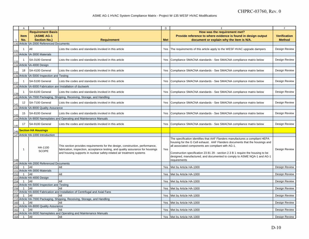
ASME AG-1 HVAC System Compliance Matrix - Project W-135 WESF HVAC Modifications
1
A B C D E F
Item No.
Requirement Basis (ASME AG-1 Section No.) Requirement Met
How was the requirement met?Provide reference to where evidence is found in design output
document or explain why the item is N/A.Verification
Method130
131
132
133
134
135
136
137
138
139
140
141
142
143
144
145
146
147
148
149
150
151
152
153
154
155
156
157
158
159
160
161
162
163
164
Article SA-2000 Referenced Documents
1 All Lists the codes and standards invoked in this article Yes The requirements of this article apply to the WESF HVAC upgrade dampers Design Review
Article SA-3000 Materials
1 SA-3100 General Lists the codes and standards invoked in this article Yes Compliance SMACNA standards - See SMACNA compliance matrix below Design Review
Article SA-4000 Design
18 SA-4100 General Lists the codes and standards invoked in this article Yes Compliance SMACNA standards - See SMACNA compliance matrix below Design Review
Article SA-5000 Inspection and Testing
1 SA-5100 General Lists the codes and standards invoked in this article Yes Compliance SMACNA standards - See SMACNA compliance matrix below Design Review
Article SA-6000 Fabrication and Installation of ductwork
1 SA-6100 General Lists the codes and standards invoked in this article Yes Compliance SMACNA standards - See SMACNA compliance matrix below Design Review
Article SA-7000 Packaging, Shipping, Receiving, Storage, and Handling
12 SA-7100 General Lists the codes and standards invoked in this article Yes Compliance SMACNA standards - See SMACNA compliance matrix below Design Review
Article SA-8000 Quality Assurance
15 SA-8100 General Lists the codes and standards invoked in this article Yes Compliance SMACNA standards - See SMACNA compliance matrix below Design Review
Article SA-9000 Nameplates and Operating and Maintenance Manuals
17 SA-9100 General Lists the codes and standards invoked in this article Yes Compliance SMACNA standards - See SMACNA compliance matrix below Design Review
Section HA HousingsArticle HA-1000 Introduction
1 HA-1100SCOPE
This section provides requirements for the design, construction, performance, fabrication, inspection, acceptance testing, and quality assurance for housings and housing supports in nuclear safety-related air treatment systems
Yes
The specification identifies that AAF Flanders manufactures a compliant HEPA housing for the G Cell exhaust. AAF Flanders documents that the housings and all associated components are compliant with AG-1.
Construction specification 23 81 29 - section 2.3 B 1 require the housing to be designed, manufactured, and documented to comply to ASME NQA-1 and AG-1 requirements
Design Review
Article HA-2000 Referenced Documents1 All All Yes Met by Article HA-1000 Design Review
Article HA-3000 Materials1 All All Yes Met by Article HA-1000 Design Review
Article HA-4000 Design1 All All Yes Met by Article HA-1000 Design Review
Article HA-5000 Inspection and Testing1 All All Yes Met by Article HA-1000 Design Review
Article HA-6000 Fabrication and Installation of Centrifugal and Axial Fans1 All All Yes Met by Article HA-1000 Design Review
Article HA-7000 Packaging, Shipping, Receiving, Storage, and Handling1 All All Yes Met by Article HA-1000 Design Review
Article HA-8000 Quality Assurance1 All All Yes Met by Article HA-1000 Design Review
Article HA-9000 Nameplates and Operating and Maintenance Manuals 1 All All Yes Met by Article HA-1000 Design Review
CHPRC-03760, Rev. 0
D-10
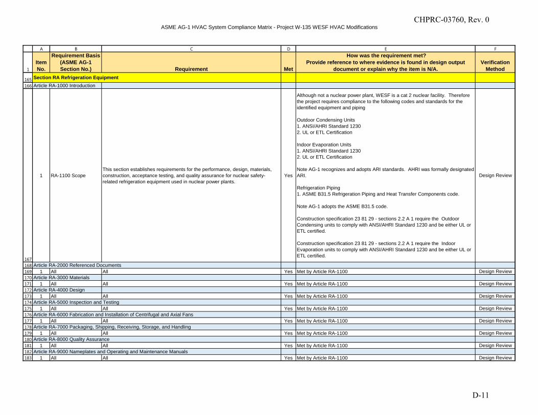
ASME AG-1 HVAC System Compliance Matrix - Project W-135 WESF HVAC Modifications
1
A B C D E F
Item No.
Requirement Basis (ASME AG-1 Section No.) Requirement Met
How was the requirement met?Provide reference to where evidence is found in design output
document or explain why the item is N/A.Verification
Method
165
166
167
168
169
170
171
172
173
174
175
176
177
178
179
180
181
182
183
Section RA Refrigeration Equipment Article RA-1000 Introduction
1 RA-1100 ScopeThis section establishes requirements for the performance, design, materials, construction, acceptance testing, and quality assurance for nuclear safety-related refrigeration equipment used in nuclear power plants.
Yes
Although not a nuclear power plant, WESF is a cat 2 nuclear facility. Therefore the project requires compliance to the following codes and standards for the identified equipment and piping
Outdoor Condensing Units1. ANSI/AHRI Standard 12302. UL or ETL Certification
Indoor Evaporation Units1. ANSI/AHRI Standard 12302. UL or ETL Certification
Note AG-1 recognizes and adopts ARI standards. AHRI was formally designated ARI.
Refrigeration Piping1. ASME B31.5 Refrigeration Piping and Heat Transfer Components code.
Note AG-1 adopts the ASME B31.5 code.
Construction specification 23 81 29 - sections 2.2 A 1 require the Outdoor Condensing units to comply with ANSI/AHRI Standard 1230 and be either UL or ETL certified.
Construction specification 23 81 29 - sections 2.2 A 1 require the Indoor Evaporation units to comply with ANSI/AHRI Standard 1230 and be either UL or ETL certified.
Design Review
Article RA-2000 Referenced Documents1 All All Yes Met by Article RA-1100 Design Review
Article RA-3000 Materials1 All All Yes Met by Article RA-1100 Design Review
Article RA-4000 Design1 All All Yes Met by Article RA-1100 Design Review
Article RA-5000 Inspection and Testing1 All All Yes Met by Article RA-1100 Design Review
Article RA-6000 Fabrication and Installation of Centrifugal and Axial Fans1 All All Yes Met by Article RA-1100 Design Review
Article RA-7000 Packaging, Shipping, Receiving, Storage, and Handling1 All All Yes Met by Article RA-1100 Design Review
Article RA-8000 Quality Assurance1 All All Yes Met by Article RA-1100 Design Review
Article RA-9000 Nameplates and Operating and Maintenance Manuals 1 All All Yes Met by Article RA-1100 Design Review
CHPRC-03760, Rev. 0
D-11
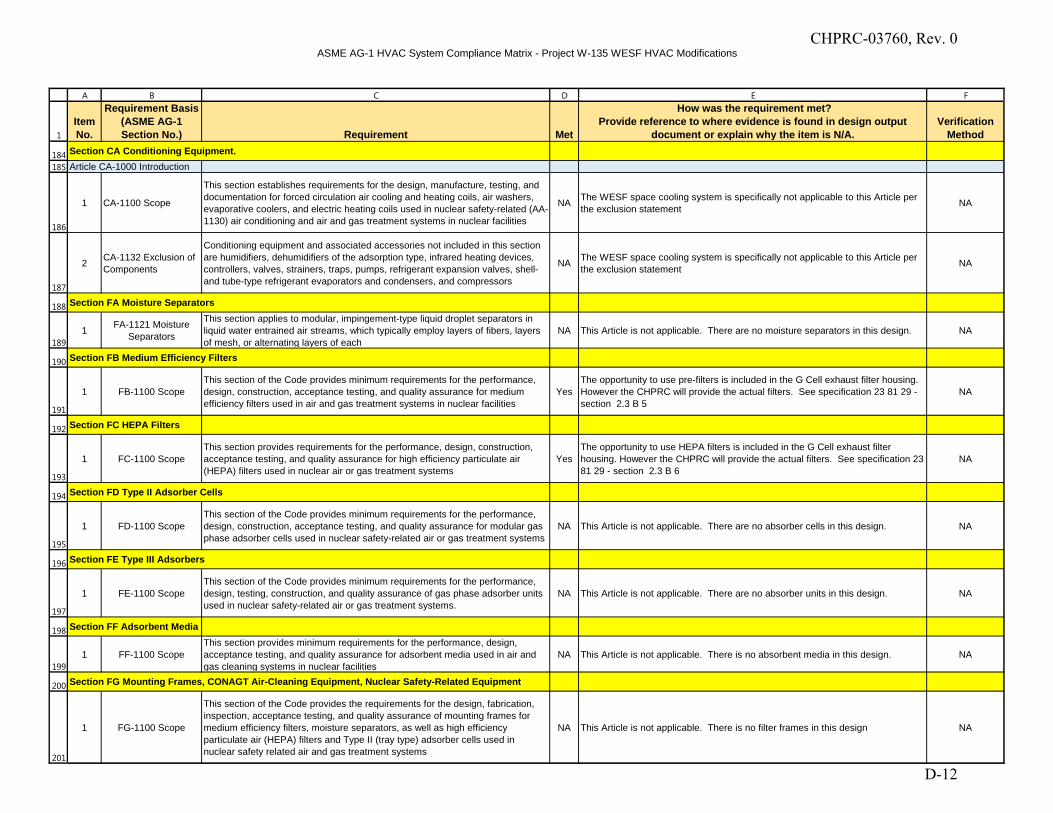
ASME AG-1 HVAC System Compliance Matrix - Project W-135 WESF HVAC Modifications
1
A B C D E F
Item No.
Requirement Basis (ASME AG-1 Section No.) Requirement Met
How was the requirement met?Provide reference to where evidence is found in design output
document or explain why the item is N/A.Verification
Method
184
185
186
187
188
189
190
191
192
193
194
195
196
197
198
199
200
201
Section CA Conditioning Equipment.Article CA-1000 Introduction
1 CA-1100 Scope
This section establishes requirements for the design, manufacture, testing, and documentation for forced circulation air cooling and heating coils, air washers, evaporative coolers, and electric heating coils used in nuclear safety-related (AA-1130) air conditioning and air and gas treatment systems in nuclear facilities
NA The WESF space cooling system is specifically not applicable to this Article per the exclusion statement NA
2 CA-1132 Exclusion of Components
Conditioning equipment and associated accessories not included in this section are humidifiers, dehumidifiers of the adsorption type, infrared heating devices, controllers, valves, strainers, traps, pumps, refrigerant expansion valves, shell- and tube-type refrigerant evaporators and condensers, and compressors
NA The WESF space cooling system is specifically not applicable to this Article per the exclusion statement NA
Section FA Moisture Separators
1 FA-1121 Moisture Separators
This section applies to modular, impingement-type liquid droplet separators in liquid water entrained air streams, which typically employ layers of fibers, layers of mesh, or alternating layers of each
NA This Article is not applicable. There are no moisture separators in this design. NA
Section FB Medium Efficiency Filters
1 FB-1100 ScopeThis section of the Code provides minimum requirements for the performance, design, construction, acceptance testing, and quality assurance for medium efficiency filters used in air and gas treatment systems in nuclear facilities
YesThe opportunity to use pre-filters is included in the G Cell exhaust filter housing. However the CHPRC will provide the actual filters. See specification 23 81 29 - section 2.3 B 5
NA
Section FC HEPA Filters
1 FC-1100 ScopeThis section provides requirements for the performance, design, construction, acceptance testing, and quality assurance for high efficiency particulate air (HEPA) filters used in nuclear air or gas treatment systems
YesThe opportunity to use HEPA filters is included in the G Cell exhaust filter housing. However the CHPRC will provide the actual filters. See specification 23 81 29 - section 2.3 B 6
NA
Section FD Type II Adsorber Cells
1 FD-1100 ScopeThis section of the Code provides minimum requirements for the performance, design, construction, acceptance testing, and quality assurance for modular gas phase adsorber cells used in nuclear safety-related air or gas treatment systems
NA This Article is not applicable. There are no absorber cells in this design. NA
Section FE Type III Adsorbers
1 FE-1100 ScopeThis section of the Code provides minimum requirements for the performance, design, testing, construction, and quality assurance of gas phase adsorber units used in nuclear safety-related air or gas treatment systems.
NA This Article is not applicable. There are no absorber units in this design. NA
Section FF Adsorbent Media
1 FF-1100 ScopeThis section provides minimum requirements for the performance, design, acceptance testing, and quality assurance for adsorbent media used in air and gas cleaning systems in nuclear facilities
NA This Article is not applicable. There is no absorbent media in this design. NA
Section FG Mounting Frames, CONAGT Air-Cleaning Equipment, Nuclear Safety-Related Equipment
1 FG-1100 Scope
This section of the Code provides the requirements for the design, fabrication, inspection, acceptance testing, and quality assurance of mounting frames for medium efficiency filters, moisture separators, as well as high efficiency particulate air (HEPA) filters and Type II (tray type) adsorber cells used in nuclear safety related air and gas treatment systems
NA This Article is not applicable. There is no filter frames in this design NA
CHPRC-03760, Rev. 0
D-12
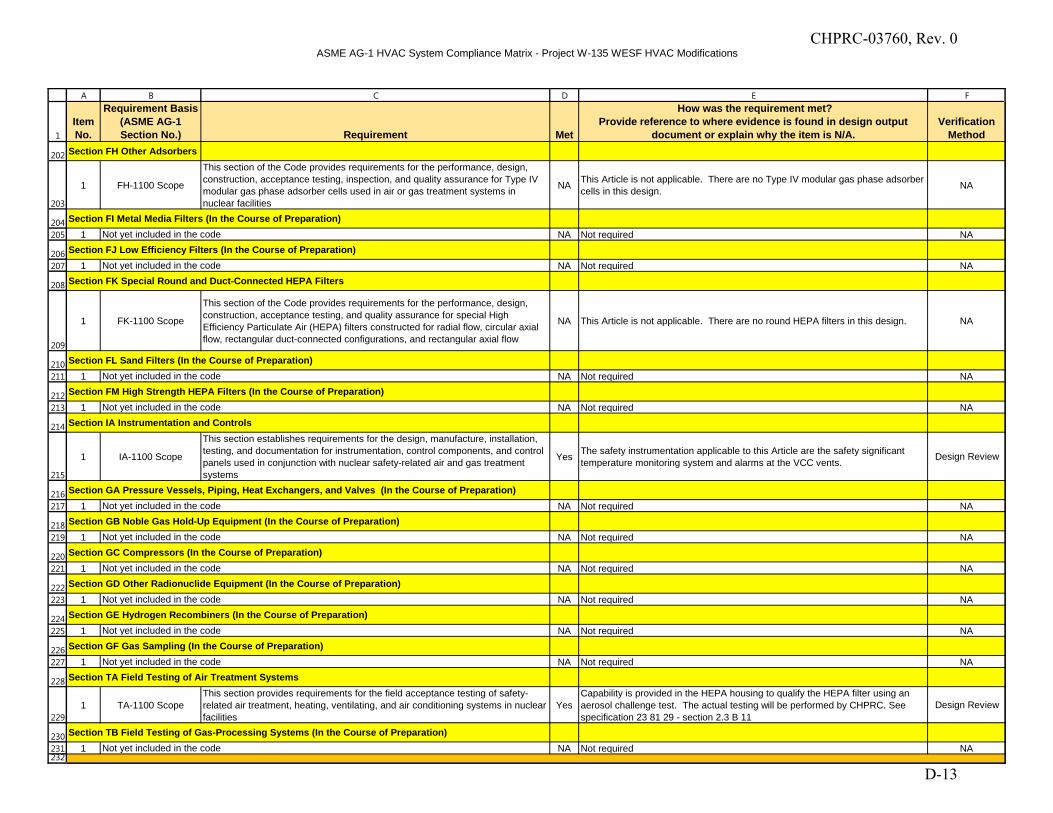
ASME AG-1 HVAC System Compliance Matrix - Project W-135 WESF HVAC Modifications
1
A B C D E F
Item No.
Requirement Basis (ASME AG-1 Section No.) Requirement Met
How was the requirement met?Provide reference to where evidence is found in design output
document or explain why the item is N/A.Verification
Method
202
203
204
205
206
207
208
209
210
211
212
213
214
215
216
217
218
219
220
221
222
223
224
225
226
227
228
229
230
231232
Section FH Other Adsorbers
1 FH-1100 Scope
This section of the Code provides requirements for the performance, design, construction, acceptance testing, inspection, and quality assurance for Type IV modular gas phase adsorber cells used in air or gas treatment systems in nuclear facilities
NA This Article is not applicable. There are no Type IV modular gas phase adsorber cells in this design. NA
Section FI Metal Media Filters (In the Course of Preparation)1 Not yet included in the code NA Not required NA
Section FJ Low Efficiency Filters (In the Course of Preparation)1 Not yet included in the code NA Not required NA
Section FK Special Round and Duct-Connected HEPA Filters
1 FK-1100 Scope
This section of the Code provides requirements for the performance, design, construction, acceptance testing, and quality assurance for special High Efficiency Particulate Air (HEPA) filters constructed for radial flow, circular axial flow, rectangular duct-connected configurations, and rectangular axial flow
NA This Article is not applicable. There are no round HEPA filters in this design. NA
Section FL Sand Filters (In the Course of Preparation)1 Not yet included in the code NA Not required NA
Section FM High Strength HEPA Filters (In the Course of Preparation)1 Not yet included in the code NA Not required NA
Section IA Instrumentation and Controls
1 IA-1100 Scope
This section establishes requirements for the design, manufacture, installation, testing, and documentation for instrumentation, control components, and control panels used in conjunction with nuclear safety-related air and gas treatment systems
Yes The safety instrumentation applicable to this Article are the safety significant temperature monitoring system and alarms at the VCC vents. Design Review
Section GA Pressure Vessels, Piping, Heat Exchangers, and Valves (In the Course of Preparation)1 Not yet included in the code NA Not required NA
Section GB Noble Gas Hold-Up Equipment (In the Course of Preparation)1 Not yet included in the code NA Not required NA
Section GC Compressors (In the Course of Preparation)1 Not yet included in the code NA Not required NA
Section GD Other Radionuclide Equipment (In the Course of Preparation)1 Not yet included in the code NA Not required NA
Section GE Hydrogen Recombiners (In the Course of Preparation)1 Not yet included in the code NA Not required NA
Section GF Gas Sampling (In the Course of Preparation)1 Not yet included in the code NA Not required NA
Section TA Field Testing of Air Treatment Systems
1 TA-1100 ScopeThis section provides requirements for the field acceptance testing of safety-related air treatment, heating, ventilating, and air conditioning systems in nuclear facilities
YesCapability is provided in the HEPA housing to qualify the HEPA filter using an aerosol challenge test. The actual testing will be performed by CHPRC. See specification 23 81 29 - section 2.3 B 11
Design Review
Section TB Field Testing of Gas-Processing Systems (In the Course of Preparation)1 Not yet included in the code NA Not required NA
CHPRC-03760, Rev. 0
D-13
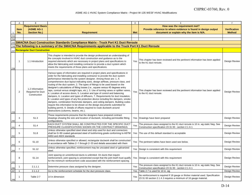
ASME AG-1 HVAC System Compliance Matrix - Project W-135 WESF HVAC Modifications
1
A B C D E F
Item No.
Requirement Basis (ASME AG-1 Section No.) Requirement Met
How was the requirement met?Provide reference to where evidence is found in design output
document or explain why the item is N/A.Verification
Method233
234
235
236
237
238
239
240
241
242
243
244
245
246
247
248
Rectangular Duct Construction
1 1.1 Introduction
This chapter is intended to provide the design professional an understanding of the concepts involved in HVAC duct construction and guidance as to the required elements which are necessary in project plans and specifications to allow the fabricating and installing contractor to provide a duct system which meets the requirements of those plans and specifications.
Yes This chapter has been reviewed and the pertinent information has been applied to the K1 duct reroute. Design Review
21.2 Information
Required for Duct Construction
Various types of information are required in project plans and specifications in order for the fabricating and installing contractor to provide the duct system performance intended by the system designer. Among those are: 1. A comprehensive duct layout indicating sizes, design airflows, pressure class, and routing of the duct system, 2. The types of fittings to be used based on the designer’s calculations of fitting losses (i.e., square versus 45 degrees entry
taps, conical versus straight taps, etc.), 3. Use of turning vanes or splitter vanes, 4. Location of access doors, 5. Location and type of control and balancing dampers, 6. Location and types of diffusers, 7. Requirements for duct insulation, 8. Location and types of any fire protection device including fire dampers, smoke dampers, combination fire/smoke dampers, and ceiling dampers. Building codes require this information to be shown on the design documents submitted for building permit, 9. Details of offsets required to route ductwork around obstructions (columns, beams, etc.).
Yes This chapter has been reviewed and the pertinent information has been applied to the K1 duct reroute.
Design Review
3 S1.3These requirements presume that the designers have prepared contract drawings showing the size and location of ductwork, including permissible fitting configurations.
Yes Drawings have been prepared Design Review
4 S1.4 EACH DUCT SYSTEM SHALL BE CONSTRUCTED FOR THE SPECIFIC DUCT PRESSURE CLASSIFICATIONS SHOWN ON THE CONTRACT DRAWINGS. Yes The pressure class assigned to the K1 duct reroute is 10 in. wg static Neg. See
Construction specification 23 31 00 - section 2.1 A 1Design Review
5 S1.8Unless otherwise specified steel sheet and strip used for duct and connectors shall be G−60 coated galvanized steel of lockforming grade conforming to ASTM
A653 and A924 standardsYes The use of this default standard is acceptable Design Review
6 S1.10 Unless otherwise specified or allowed, rectangular ductwork shall be constructed in accordance with Tables 2−1 through 2−33 and details associated with them
Yes The pertinent tables have been used see below. Design Review
7 S1.12 Unless otherwise specified, reinforcement may be uncoated steel or galvanized steel. Yes Design is consistent with this requirement Design Review
8 S1.14Joint spacing on unreinforced ducts is unlimited. On ducts that require reinforcement, joint spacing is unrestricted except that the joint itself must qualify for the minimum reinforcement code associated with the reinforcement spacing.
Yes Design is consistent with this requirement Design Review
1 2.1.1.1 Determine pressure class assigned by the designer. Yes The pressure class assigned to the K1 duct reroute is 10 in. wg static Neg. See Construction specification 23 31 00 - section 2.1 A 1 Design Review
1 2.1.1.2 Go to the reinforcement schedule for the duct pressure class. Yes Table 2-7 is used for 10 in. wg Design Review
1 Table 2-7 14 in dimension Yes No reinforcement is required if 18 gauge or thicker material used. Specification 23 31 00 section 2.1 A 3 requires a minimum of 16 gauge material. Design Review
SMACNA Duct Construction Standards Compliance Matrix - Truck Port K1 Duct RerouteThe following is a summary of the SMACNA Requirements applicable to the Truck Port K1 Duct Reroute
CHPRC-03760, Rev. 0
D-14
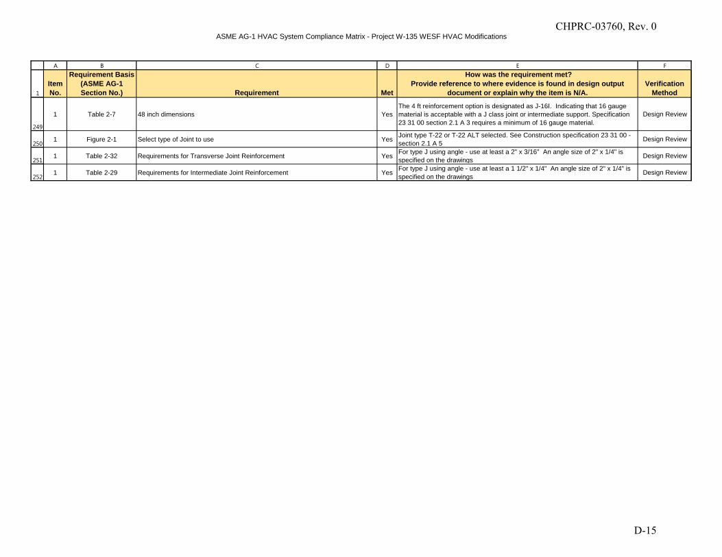
ASME AG-1 HVAC System Compliance Matrix - Project W-135 WESF HVAC Modifications
1
A B C D E F
Item No.
Requirement Basis (ASME AG-1 Section No.) Requirement Met
How was the requirement met?Provide reference to where evidence is found in design output
document or explain why the item is N/A.Verification
Method
249
250
251
252
1 Table 2-7 48 inch dimensions YesThe 4 ft reinforcement option is designated as J-16I. Indicating that 16 gauge material is acceptable with a J class joint or intermediate support. Specification 23 31 00 section 2.1 A 3 requires a minimum of 16 gauge material.
Design Review
1 Figure 2-1 Select type of Joint to use Yes Joint type T-22 or T-22 ALT selected. See Construction specification 23 31 00 - section 2.1 A 5 Design Review
1 Table 2-32 Requirements for Transverse Joint Reinforcement Yes For type J using angle - use at least a 2" x 3/16" An angle size of 2" x 1/4" is specified on the drawings Design Review
1 Table 2-29 Requirements for Intermediate Joint Reinforcement Yes For type J using angle - use at least a 1 1/2" x 1/4" An angle size of 2" x 1/4" is specified on the drawings Design Review
CHPRC-03760, Rev. 0
D-15

CHPRC-03760, Rev. 0
E-1
APPENDIX E
FDC DESIGN VERIFICATION MATRIX
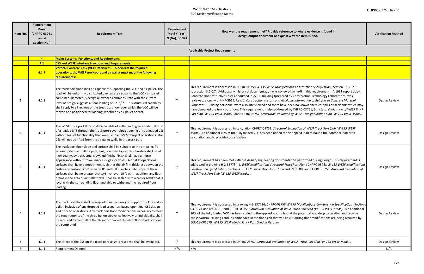
W-135 WESF ModificationsFDC Design Verification Matrix
Item No.
Requirement Basis
(CHPRC-03011 rev. 4
Section No.)
Requirement TextRequirement Met? Y (Yes),
N (No), or N/A
How was the requirement met? Provide reference to where evidence is found indesign output document or explain why the item is N/A.
Verification Method
4 Major Systems, Functions, and Requirements4.1 CSS and WESF Interface Functions and Requirements
4.1.1Vertical Concrete Cask (VCC) Interfaces - To perform the required operations, the WESF truck port and air pallet must meet the following requirements:
1 4.1.1
The truck port floor shall be capable of supporting the VCC and air pallet. The load will be uniformly distributed over an area equal to the VCC / air pallet combined diameter. A design allowance commensurate with the current level of design suggests a floor loading of 22 lb/in2. This structural capability shall apply to all regions of the truck port floor over which the VCC will be moved and positioned for loading, whether by air pallet or cart
Y
This requirement is addressed in CHPRC-03758 W-135 WESF Modifications Construction Specification , section 03 30 21 subsection 3.2.C.7. Additionally, historical documentation was reviewed regarding this requirement. A 1981 report titled Concrete Nondestructive Tests Conducted in 225-B Building (prepared by Construction Technology Laboratories) was reviewed, along with HNF-3915, Rev. 0, Construction History and Available Information of Reinforced Concrete Material Properties. Building personnel were also interviewed and there have been no known chemical spills or accidents which may have damaged the truck port floor. This requirement is also addressed by CHPRC-03751, Structural Evaluation of WESF Truck Port Slab (W-135 WESF Mods) , and CHPRC-03752, Structural Evaluation of WESF Transfer Station Slab (W-135 WESF Mods).
Design Review
2 4.1.1
The WESF truck port floor shall be capable of withstanding an accidental drop of a loaded DTS through the truck port cover block opening onto a loaded CSS without loss of functionality that would impact MCSC Project operations. The CSS will not be lifted from the air pallet while in the truck port
YThis requirement is addressed in calculation CHPRC-03751, Structural Evaluation of WESF Truck Port Slab (W-135 WESF Mods). An additional 10% of the fully loaded VCC has been added to the applied load to bound the potential load drop calculation and to provide conservatism.
Design Review
3 4.1.1
The truck port floor slope and surface shall be suitable to the air pallet. To accommodate air pallet operations, concrete top surface finishes shall be of high quality, smooth, steel troweled finish. Finish shall have uniform appearance without trowel marks, ridges, or voids. Air pallet operational surfaces shall have a smoothness such that the air film thickness between the caster and surface is between 0.001 and 0.005 inches. The slope of these surfaces shall be no greater that 1/4 inch over 10 feet. In addition, any floor drains in the area of air pallet travel shall be sealed with a cap or blank that is level with the surrounding floor and able to withstand the required floor loading.
Y
This requirement has been met with the design/engineering documentation performed during design. This requirement is addressed in drawing H-2-837734-1, WESF Modifications Structural Truck Port Plan ; CHPRC-03758 W-135 WESF Modifications Construction Specification, Sections 03 30 21 subsection 3.2.C.7.c.ii and 09 96 00; and CHPRC-03751 Structural Evaluation of WESF Truck Port Slab (W-135 WESF Mods) .
Design Review
4 4.1.1
The truck port floor shall be upgraded as necessary to support the CSS and air pallet, inclusive of any dropped load scenarios, based upon final CSS design and prior to operations. Any truck port floor modifications necessary to meet the requirements of the three bullets above, collectively or individually, shall be required to meet all of the above requirements when floor modifications are completed
Y
This requirement is addressed in drawing H-2-837734, CHPRC-03758 W-135 Modifications Construction Specification , Sections 03 30 21 and 09 96 00, and CHPRC-03751, Structural Evaluation of WESF Truck Port Slab (W-135 WESF Mods). A n additional 10% of the fully loaded VCC has been added to the applied load to bound the potential load drop calculation and provide conservatism. Existing conduits embedded in the floor slab that will be cut during floor modifications are being rerouted by ECR-18-001579, W-135 WESF Mods: Truck Port Conduit Reroute.
Design Review
5 4.1.1 The effect of the CSS on the truck port seismic response shall be evaluated. Y This requirement is addressed in CHPRC-03751, Structural Evaluation of WESF Truck Port Slab (W-135 WESF Mods) . Design Review
6 4.1.1 Requirement Deleted N/A N/A N/A
Applicable Project Requirements
CHPRC-03760, Rev. 0
E-2
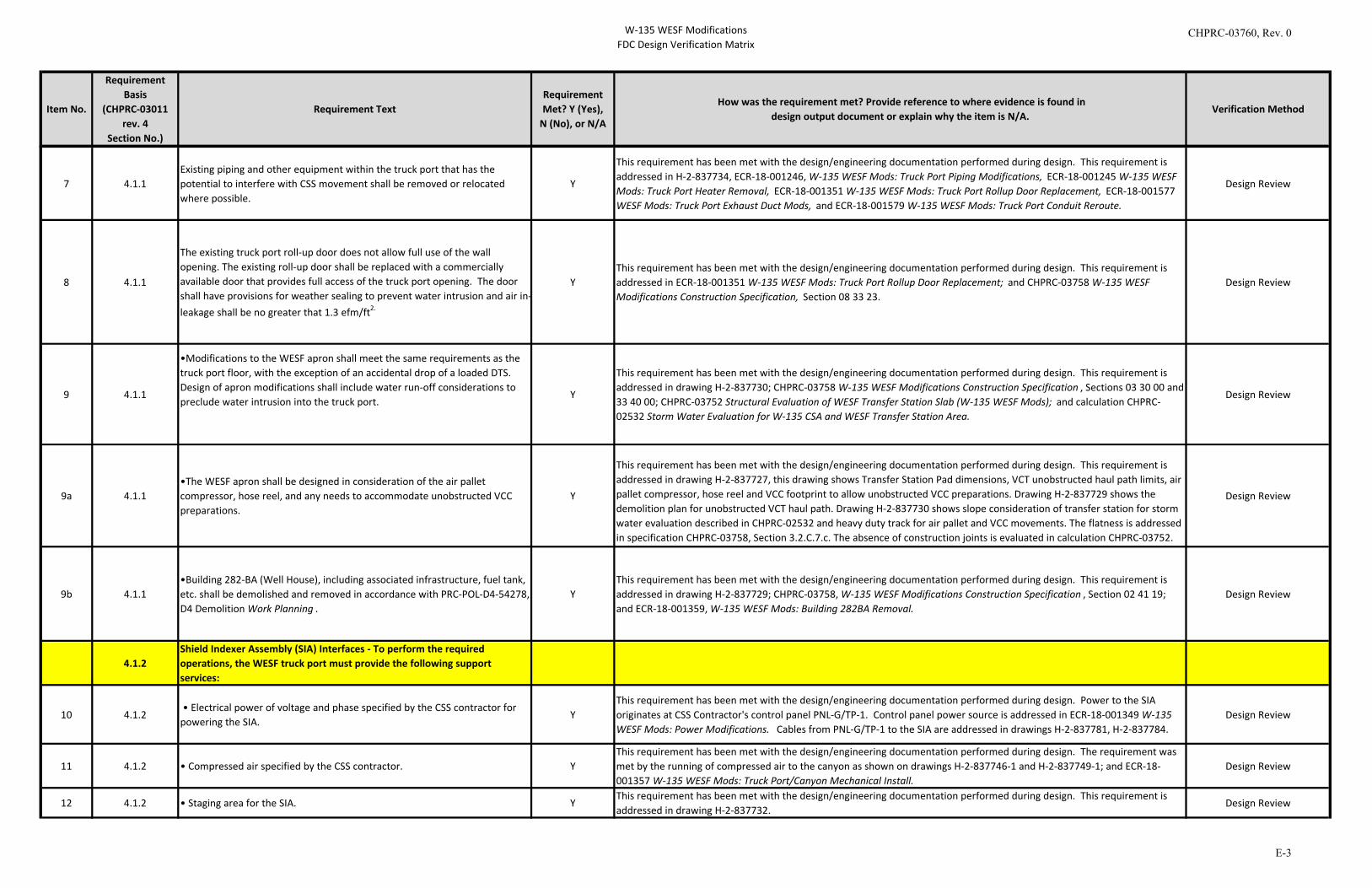
W-135 WESF ModificationsFDC Design Verification Matrix
Item No.
Requirement Basis
(CHPRC-03011 rev. 4
Section No.)
Requirement TextRequirement Met? Y (Yes),
N (No), or N/A
How was the requirement met? Provide reference to where evidence is found indesign output document or explain why the item is N/A.
Verification Method
7 4.1.1Existing piping and other equipment within the truck port that has the potential to interfere with CSS movement shall be removed or relocated where possible.
Y
This requirement has been met with the design/engineering documentation performed during design. This requirement is addressed in H-2-837734, ECR-18-001246, W-135 WESF Mods: Truck Port Piping Modifications, ECR-18-001245 W-135 WESF Mods: Truck Port Heater Removal, ECR-18-001351 W-135 WESF Mods: Truck Port Rollup Door Replacement, ECR-18-001577 WESF Mods: Truck Port Exhaust Duct Mods, and ECR-18-001579 W-135 WESF Mods: Truck Port Conduit Reroute.
Design Review
8 4.1.1
The existing truck port roll-up door does not allow full use of the wall opening. The existing roll-up door shall be replaced with a commercially available door that provides full access of the truck port opening. The door shall have provisions for weather sealing to prevent water intrusion and air in-leakage shall be no greater that 1.3 efm/ft2.
YThis requirement has been met with the design/engineering documentation performed during design. This requirement is addressed in ECR-18-001351 W-135 WESF Mods: Truck Port Rollup Door Replacement; and CHPRC-03758 W-135 WESF Modifications Construction Specification, Section 08 33 23.
Design Review
9 4.1.1
•Modifications to the WESF apron shall meet the same requirements as the truck port floor, with the exception of an accidental drop of a loaded DTS. Design of apron modifications shall include water run-off considerations to preclude water intrusion into the truck port.
Y
This requirement has been met with the design/engineering documentation performed during design. This requirement is addressed in drawing H-2-837730; CHPRC-03758 W-135 WESF Modifications Construction Specification , Sections 03 30 00 and 33 40 00; CHPRC-03752 Structural Evaluation of WESF Transfer Station Slab (W-135 WESF Mods); and calculation CHPRC-02532 Storm Water Evaluation for W-135 CSA and WESF Transfer Station Area.
Design Review
9a 4.1.1•The WESF apron shall be designed in consideration of the air pallet compressor, hose reel, and any needs to accommodate unobstructed VCC preparations.
Y
This requirement has been met with the design/engineering documentation performed during design. This requirement is addressed in drawing H-2-837727, this drawing shows Transfer Station Pad dimensions, VCT unobstructed haul path limits, air pallet compressor, hose reel and VCC footprint to allow unobstructed VCC preparations. Drawing H-2-837729 shows the demolition plan for unobstructed VCT haul path. Drawing H-2-837730 shows slope consideration of transfer station for storm water evaluation described in CHPRC-02532 and heavy duty track for air pallet and VCC movements. The flatness is addressed in specification CHPRC-03758, Section 3.2.C.7.c. The absence of construction joints is evaluated in calculation CHPRC-03752.
Design Review
9b 4.1.1•Building 282-BA (Well House), including associated infrastructure, fuel tank, etc. shall be demolished and removed in accordance with PRC-POL-D4-54278, D4 Demolition Work Planning .
YThis requirement has been met with the design/engineering documentation performed during design. This requirement is addressed in drawing H-2-837729; CHPRC-03758, W-135 WESF Modifications Construction Specification , Section 02 41 19; and ECR-18-001359, W-135 WESF Mods: Building 282BA Removal.
Design Review
4.1.2Shield Indexer Assembly (SIA) Interfaces - To perform the required operations, the WESF truck port must provide the following support services:
10 4.1.2 • Electrical power of voltage and phase specified by the CSS contractor for powering the SIA.
Y This requirement has been met with the design/engineering documentation performed during design. Power to the SIA originates at CSS Contractor's control panel PNL-G/TP-1. Control panel power source is addressed in ECR-18-001349 W-135 WESF Mods: Power Modifications. Cables from PNL-G/TP-1 to the SIA are addressed in drawings H-2-837781, H-2-837784.
Design Review
11 4.1.2 • Compressed air specified by the CSS contractor. YThis requirement has been met with the design/engineering documentation performed during design. The requirement was met by the running of compressed air to the canyon as shown on drawings H-2-837746-1 and H-2-837749-1; and ECR-18-001357 W-135 WESF Mods: Truck Port/Canyon Mechanical Install.
Design Review
12 4.1.2 • Staging area for the SIA. YThis requirement has been met with the design/engineering documentation performed during design. This requirement is addressed in drawing H-2-837732.
Design Review
CHPRC-03760, Rev. 0
E-3
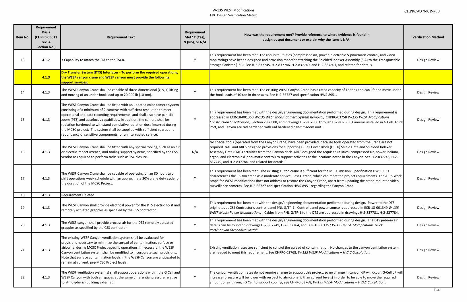
W-135 WESF ModificationsFDC Design Verification Matrix
Item No.
Requirement Basis
(CHPRC-03011 rev. 4
Section No.)
Requirement TextRequirement Met? Y (Yes),
N (No), or N/A
How was the requirement met? Provide reference to where evidence is found indesign output document or explain why the item is N/A.
Verification Method
13 4.1.2 • Capability to attach the SIA to the TSCB. Y
This requirement has been met. The requisite utilities (compressed air, power, electronic & pnuematic control, and video monitoring) have beeen designed and provision madefor attaching the Shielded Indexer Assembly (SIA) to the Transportable Storage Canister (TSC). See H-2-837745, H-2-837746, H-2-837749, and H-2-837801, and related for details.
Design Review
4.1.3Dry Transfer System (DTS) Interfaces - To perform the required operations, the WESF canyon crane and WESF canyon must provide the following support services:
14 4.1.3The WESF Canyon Crane shall be capable of three-dimensional (x, y, z) lifting and moving of an under-hook load up to 20,000 lb (10 ton).
YThis requirement has been met. The existing WESF Canyon Crane has a rated capacity of 15 tons and can lift and move under-the-hook loads of 10 ton in three axes. See H-2-66727 and specification HWS-8951.
Design Review
15 4.1.3
The WESF Canyon Crane shall be fitted with an updated color camera system consisting of a minimum of 2 cameras with sufficient resolution to meet operational and data recording requirements, and shall also have pan-tilt-zoom (PTZ) and autofocus capabilities. In addition, the camera shall be radiation hardened to withstand cumulative radiation dose incurred during the MCSC project. The system shall be supplied with sufficient spares and redundancy of sensitive components for uninterrupted service.
Y
This requirement has been met with the design/engineering documentation performed during design. This requirement is addressed in ECR-18-001360 W-135 WESF Mods: Camera System Removal; CHPRC-03758 W-135 WESF Modifications Construction Specification, Section 28 23 00, and drawings H-2-837800 through H-2-837803. Cameras installed in G Cell, Truck Port, and Canyon are rad hardened with rad hardened pan-tilt-zoom unit.
Design Review
16 4.1.3The WESF Canyon Crane shall be fitted with any special tooling, such as an air or electric impact wrench, and tooling support systems, specified by the CSS vendor as required to perform tasks such as TSC closure.
N/A
No special tools (operated from the Canyon Crane) have been provided, because tools operated from the Crane are not required. NAC and ARES designed provisions for supporting G Cell Cover Block (GBLK) Shield Gate and Shielded Indexer Assembly Gate (SIAG) activities from the Canyon deck. ARES designed the requisite utilities (compressed air, power, helium, argon, and electronic & pneumatic control) to support activities at the locations noted in the Canyon. See H-2-837745, H-2-837749, and H-2-837784, and related for details.
Design Review
17 4.1.3The WESF Canyon Crane shall be capable of operating on an 80 hour, two shift operations week schedule with an approximate 30% crane duty cycle for the duration of the MCSC Project.
Y
This requirement has been met. The existing 15 ton crane is sufficient for the MCSC mission. Specification HWS-8951 characterizes the 15-ton crane as a moderate service Class C crane, which can meet the project requirements. The ARES work scope for WESF modifications does not address or restore the Canyon Crane, apart from updating the crane-mounted video surveillance cameras. See H-2-66727 and specification HWS-8951 regarding the Canyon Crane.
Design Review
18 4.1.3 Requirement Deleted
19 4.1.3The WESF Canyon shall provide electrical power for the DTS electric hoist and remotely actuated grapples as specified by the CSS contractor.
YThis requirement has been met with the design/engineering documentation performed during design. Power to the DTS originates at CSS Contractor's control panel PNL-G/TP-1. Control panel power source is addressed in ECR-18-001349 W-135 WESF Mods: Power Modifications . Cables from PNL-G/TP-1 to the DTS are addressed in drawings H-2-837781, H-2-837784.
Design Review
20 4.1.3The WESF canyon shall provide process air for the DTS remotely actuated grapples as specified by the CSS contractor
YThis requirement has been met with the design/engineering documentation performed during design. The DTS process air details can be found on drawings H-2-837749, H-2-837764, and ECR-18-001357 W-135 WESF Modifications Truck Port/Canyon Mechanical Install.
Design Review
21 4.1.3
The existing WESF Canyon ventilation system shall be evaluated for provisions necessary to minimize the spread of contamination, surface or airborne, during MCSC Project-specific operations. If necessary, the WESF Canyon ventilation system shall be modified to incorporate such provisions. Note that surface contamination levels in the WESF Canyon are anticipated to remain at current, pre-MCSC Project levels.
YExisting ventilation rates are sufficient to control the spread of contamination. No changes to the canyon ventilation system are needed to meet this requirement. See CHPRC-03768, W-135 WESF Modifications – HVAC Calculation.
Design Review
22 4.1.3The WESF ventilation system(s) shall support operations within the G Cell and WESF Canyon with both air spaces at the same differential pressure relative to atmospheric (building external).
YThe canyon ventilation rates do not require change to support this project, so no change in canyon dP will occur. G-Cell dP will increase (pressure will be lower with respect to atmospheric than current levels) in order to be able to move the required amount of air through G Cell to support cooling, see CHPRC-03768, W-135 WESF Modifications – HVAC Calculation .
Design Review
CHPRC-03760, Rev. 0
E-4

W-135 WESF ModificationsFDC Design Verification Matrix
Item No.
Requirement Basis
(CHPRC-03011 rev. 4
Section No.)
Requirement TextRequirement Met? Y (Yes),
N (No), or N/A
How was the requirement met? Provide reference to where evidence is found indesign output document or explain why the item is N/A.
Verification Method
23 4.1.3The WESF canyon ventilation system shall be capable of maintaining an ambient air temperature of less than or equal to 80° F with a total design heat load of 17,235 Watts.
YThis requirement has been met with the addition of additional cooling to the canyon. See drawing H-2-837771. Supporting calculation are identified in CHPRC-03768, W-135 WESF Modifications – HVAC Calculations .
Design Review
4.1.4
Modified G Cell Canyon Cover Block and Transfer Gate Interfaces - To perform the required MCSC Project operations, the WESF Canyon must provide the following interface/support services for the modified G Cell cover block:
24 4.1.4 Requirement Deleted N/A N/A N/A
25 4.1.4
The means and ways of delivery of the new G Cell Canyon Cover Block into WESF and G Cell shall be evaluated to ensure the physical pathways exist and the lifting/hauling mechanisms are suitable and capable to safety replace this cover block.
Y
This requirement has been met as the new G Cell Canyon Cover Block has been design to be in four sections. The sections can be brought up through the Canyon Truck Port opening. CHPRC-03972, Appendix A, 30059-106, Auxilary Lifting Rigs , will be used to lift/haul all cover blocks. Design of all four cover block can be found in CHPRC-03972, Appendix A, 30059-200 THRU 204.
Design Review
4.1.5Automated Welding System Interfaces - To perform the required operations, the canyon must provide the following support services:
26 4.1.5 • Electrical power, three-phase rated at 480 V and 60 A. Y
This requirement has been met with the design/engineering documentation performed during design. AWS Liburdi vendor data indicates power input of 30A 480V 3ph via cord and plug. Existing weld receptacle WRCPT-225B-CAN-1, rated 100A 480V 3ph with integral fused disconnect switch, will be used to provide power to a portable power cart which will provide a 30A circuit to the Liburdi Power Source unit. AWS arrangement is shown in drawings H-2-837784 and H-2-837795, and portable power cart is specified in CHPRC-03758 W-135 WESF Modifications Construction Specification.
Design Review
27 4.1.5 • Argon gas supplies and associated plumbing and safety/relief valving. YThis requirement has been met with the design media. The drawings that identify the Argon gas supply and routing are H-2-837748, H-2-837749, and H-2-837750.
Design Review
28 4.1.5 • Monitoring instrumentation for argon storage levels. YThis requirement has been met with the design media identifying the Argon gas manifold, see drawing H-2-837750. Pressure gauges have been provided to monitor compressed argon storage and remaining level (i.e., pressure).
Design Review
29 4.1.5 Requirement Deleted N/A N/A N/A
30 4.1.5 Requirement Deleted N/A N/A N/A
31 4.1.5• Sufficient remote capability to support Automated Welding System operation.
Y
This requirement has been met with the design/engineering documentation performed during design. This requirement is addressed in drawing H-2-837780 which locates the Remote Viewing Console in the Operating Gallery, and AWS block diagram drawing H-2-837795 which shows interconnection of components of the AWS system. The Remote Viewing Console will be portable with cord and plug control, video, and power wiring that can be removed when the Remote Viewing Station is not in use. The existing 15-ton Canyon Crane will be used to remove and install the AWS as shown in H-2-837705.
Design Review
32 4.1.5 Requirement Deleted N/A N/A N/A
CHPRC-03760, Rev. 0
E-5
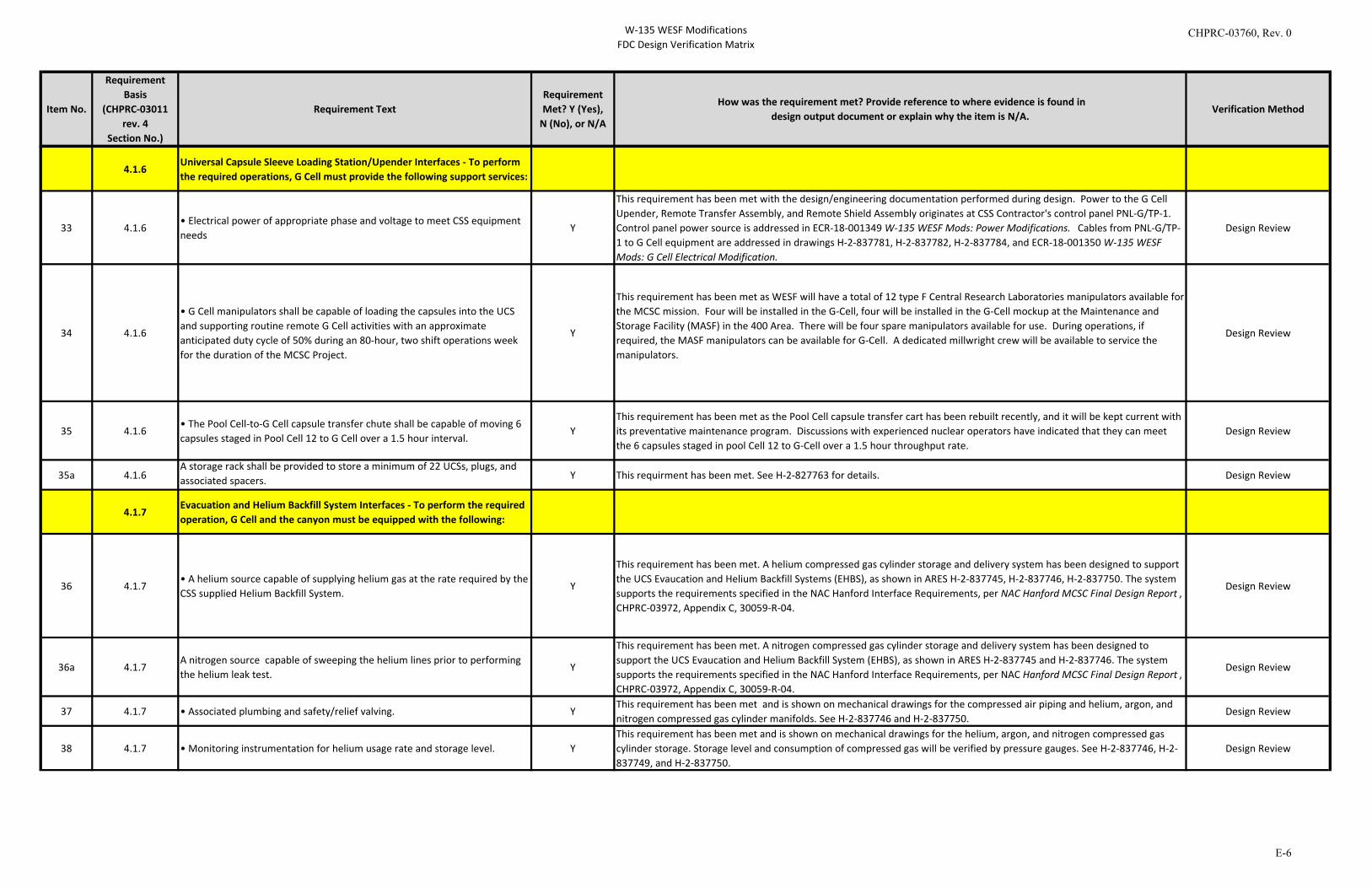
W-135 WESF ModificationsFDC Design Verification Matrix
Item No.
Requirement Basis
(CHPRC-03011 rev. 4
Section No.)
Requirement TextRequirement Met? Y (Yes),
N (No), or N/A
How was the requirement met? Provide reference to where evidence is found indesign output document or explain why the item is N/A.
Verification Method
4.1.6Universal Capsule Sleeve Loading Station/Upender Interfaces - To perform the required operations, G Cell must provide the following support services:
33 4.1.6• Electrical power of appropriate phase and voltage to meet CSS equipment needs
Y
This requirement has been met with the design/engineering documentation performed during design. Power to the G Cell Upender, Remote Transfer Assembly, and Remote Shield Assembly originates at CSS Contractor's control panel PNL-G/TP-1. Control panel power source is addressed in ECR-18-001349 W-135 WESF Mods: Power Modifications. Cables from PNL-G/TP-1 to G Cell equipment are addressed in drawings H-2-837781, H-2-837782, H-2-837784, and ECR-18-001350 W-135 WESF Mods: G Cell Electrical Modification.
Design Review
34 4.1.6
• G Cell manipulators shall be capable of loading the capsules into the UCS and supporting routine remote G Cell activities with an approximate anticipated duty cycle of 50% during an 80-hour, two shift operations week for the duration of the MCSC Project.
Y
This requirement has been met as WESF will have a total of 12 type F Central Research Laboratories manipulators available for the MCSC mission. Four will be installed in the G-Cell, four will be installed in the G-Cell mockup at the Maintenance and Storage Facility (MASF) in the 400 Area. There will be four spare manipulators available for use. During operations, if required, the MASF manipulators can be available for G-Cell. A dedicated millwright crew will be available to service the manipulators.
Design Review
35 4.1.6• The Pool Cell-to-G Cell capsule transfer chute shall be capable of moving 6 capsules staged in Pool Cell 12 to G Cell over a 1.5 hour interval.
YThis requirement has been met as the Pool Cell capsule transfer cart has been rebuilt recently, and it will be kept current with its preventative maintenance program. Discussions with experienced nuclear operators have indicated that they can meet the 6 capsules staged in pool Cell 12 to G-Cell over a 1.5 hour throughput rate.
Design Review
35a 4.1.6A storage rack shall be provided to store a minimum of 22 UCSs, plugs, and associated spacers. Y This requirment has been met. See H-2-827763 for details. Design Review
4.1.7Evacuation and Helium Backfill System Interfaces - To perform the required operation, G Cell and the canyon must be equipped with the following:
36 4.1.7• A helium source capable of supplying helium gas at the rate required by the CSS supplied Helium Backfill System.
Y
This requirement has been met. A helium compressed gas cylinder storage and delivery system has been designed to support the UCS Evaucation and Helium Backfill Systems (EHBS), as shown in ARES H-2-837745, H-2-837746, H-2-837750. The system supports the requirements specified in the NAC Hanford Interface Requirements, per NAC Hanford MCSC Final Design Report , CHPRC-03972, Appendix C, 30059-R-04.
Design Review
36a 4.1.7A nitrogen source capable of sweeping the helium lines prior to performing the helium leak test.
Y
This requirement has been met. A nitrogen compressed gas cylinder storage and delivery system has been designed to support the UCS Evaucation and Helium Backfill System (EHBS), as shown in ARES H-2-837745 and H-2-837746. The system supports the requirements specified in the NAC Hanford Interface Requirements, per NAC Hanford MCSC Final Design Report , CHPRC-03972, Appendix C, 30059-R-04.
Design Review
37 4.1.7 • Associated plumbing and safety/relief valving. YThis requirement has been met and is shown on mechanical drawings for the compressed air piping and helium, argon, and nitrogen compressed gas cylinder manifolds. See H-2-837746 and H-2-837750.
Design Review
38 4.1.7 • Monitoring instrumentation for helium usage rate and storage level. YThis requirement has been met and is shown on mechanical drawings for the helium, argon, and nitrogen compressed gas cylinder storage. Storage level and consumption of compressed gas will be verified by pressure gauges. See H-2-837746, H-2-837749, and H-2-837750.
Design Review
CHPRC-03760, Rev. 0
E-6
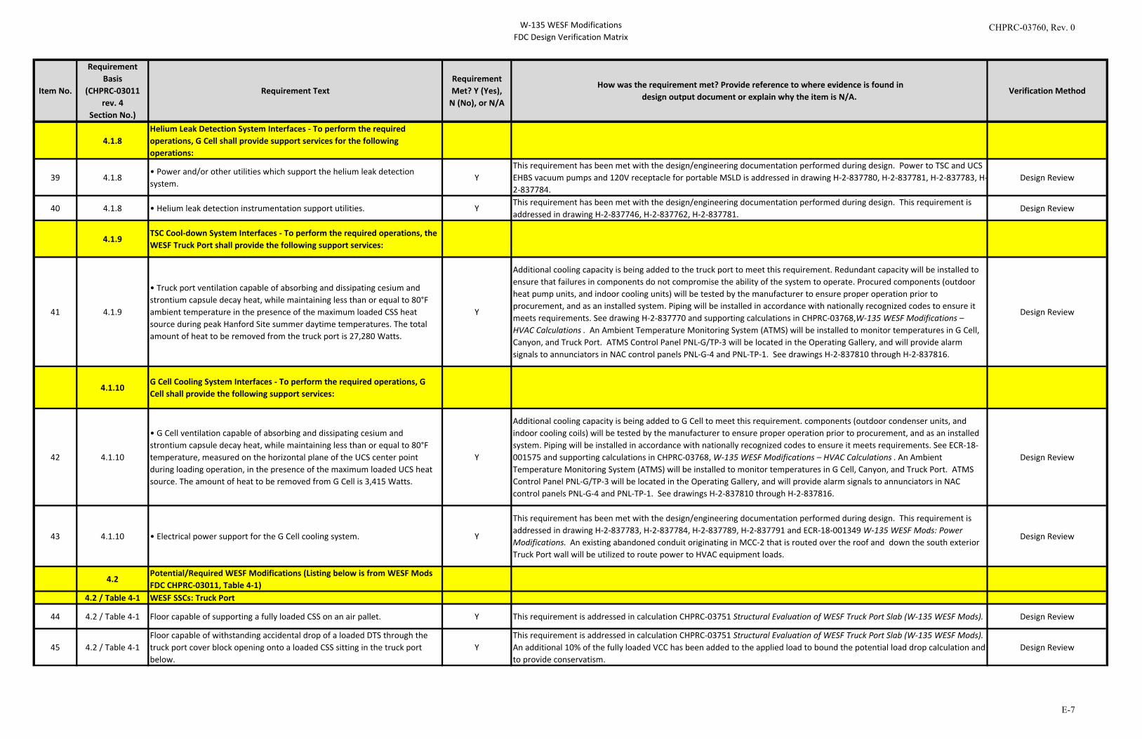
W-135 WESF ModificationsFDC Design Verification Matrix
Item No.
Requirement Basis
(CHPRC-03011 rev. 4
Section No.)
Requirement TextRequirement Met? Y (Yes),
N (No), or N/A
How was the requirement met? Provide reference to where evidence is found indesign output document or explain why the item is N/A.
Verification Method
4.1.8Helium Leak Detection System Interfaces - To perform the required operations, G Cell shall provide support services for the following operations:
39 4.1.8• Power and/or other utilities which support the helium leak detection system.
YThis requirement has been met with the design/engineering documentation performed during design. Power to TSC and UCS EHBS vacuum pumps and 120V receptacle for portable MSLD is addressed in drawing H-2-837780, H-2-837781, H-2-837783, H-2-837784.
Design Review
40 4.1.8 • Helium leak detection instrumentation support utilities. YThis requirement has been met with the design/engineering documentation performed during design. This requirement is addressed in drawing H-2-837746, H-2-837762, H-2-837781.
Design Review
4.1.9TSC Cool-down System Interfaces - To perform the required operations, the WESF Truck Port shall provide the following support services:
41 4.1.9
• Truck port ventilation capable of absorbing and dissipating cesium and strontium capsule decay heat, while maintaining less than or equal to 80°F ambient temperature in the presence of the maximum loaded CSS heat source during peak Hanford Site summer daytime temperatures. The total amount of heat to be removed from the truck port is 27,280 Watts.
Y
Additional cooling capacity is being added to the truck port to meet this requirement. Redundant capacity will be installed to ensure that failures in components do not compromise the ability of the system to operate. Procured components (outdoor heat pump units, and indoor cooling units) will be tested by the manufacturer to ensure proper operation prior to procurement, and as an installed system. Piping will be installed in accordance with nationally recognized codes to ensure it meets requirements. See drawing H-2-837770 and supporting calculations in CHPRC-03768,W-135 WESF Modifications – HVAC Calculations . An Ambient Temperature Monitoring System (ATMS) will be installed to monitor temperatures in G Cell, Canyon, and Truck Port. ATMS Control Panel PNL-G/TP-3 will be located in the Operating Gallery, and will provide alarm signals to annunciators in NAC control panels PNL-G-4 and PNL-TP-1. See drawings H-2-837810 through H-2-837816.
Design Review
4.1.10G Cell Cooling System Interfaces - To perform the required operations, G Cell shall provide the following support services:
42 4.1.10
• G Cell ventilation capable of absorbing and dissipating cesium and strontium capsule decay heat, while maintaining less than or equal to 80°F temperature, measured on the horizontal plane of the UCS center point during loading operation, in the presence of the maximum loaded UCS heat source. The amount of heat to be removed from G Cell is 3,415 Watts.
Y
Additional cooling capacity is being added to G Cell to meet this requirement. components (outdoor condenser units, and indoor cooling coils) will be tested by the manufacturer to ensure proper operation prior to procurement, and as an installed system. Piping will be installed in accordance with nationally recognized codes to ensure it meets requirements. See ECR-18-001575 and supporting calculations in CHPRC-03768, W-135 WESF Modifications – HVAC Calculations . An Ambient Temperature Monitoring System (ATMS) will be installed to monitor temperatures in G Cell, Canyon, and Truck Port. ATMS Control Panel PNL-G/TP-3 will be located in the Operating Gallery, and will provide alarm signals to annunciators in NAC control panels PNL-G-4 and PNL-TP-1. See drawings H-2-837810 through H-2-837816.
Design Review
43 4.1.10 • Electrical power support for the G Cell cooling system. Y
This requirement has been met with the design/engineering documentation performed during design. This requirement is addressed in drawing H-2-837783, H-2-837784, H-2-837789, H-2-837791 and ECR-18-001349 W-135 WESF Mods: Power Modifications. An existing abandoned conduit originating in MCC-2 that is routed over the roof and down the south exterior Truck Port wall will be utilized to route power to HVAC equipment loads.
Design Review
4.2Potential/Required WESF Modifications (Listing below is from WESF Mods FDC CHPRC-03011, Table 4-1)
4.2 / Table 4-1 WESF SSCs: Truck Port
44 4.2 / Table 4-1 Floor capable of supporting a fully loaded CSS on an air pallet. Y This requirement is addressed in calculation CHPRC-03751 Structural Evaluation of WESF Truck Port Slab (W-135 WESF Mods). Design Review
45 4.2 / Table 4-1Floor capable of withstanding accidental drop of a loaded DTS through the truck port cover block opening onto a loaded CSS sitting in the truck port below.
YThis requirement is addressed in calculation CHPRC-03751 Structural Evaluation of WESF Truck Port Slab (W-135 WESF Mods). An additional 10% of the fully loaded VCC has been added to the applied load to bound the potential load drop calculation and to provide conservatism.
Design Review
CHPRC-03760, Rev. 0
E-7
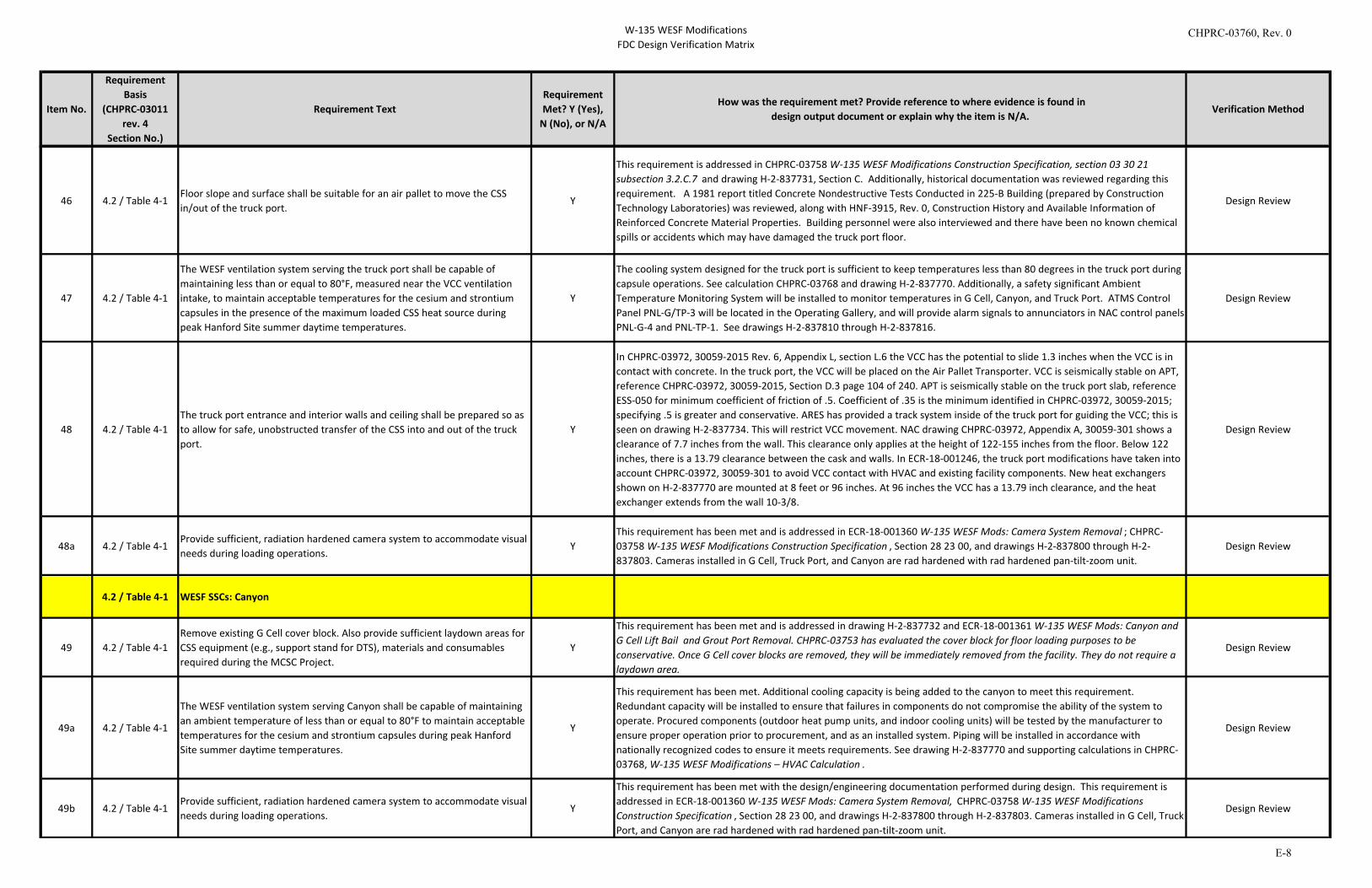
W-135 WESF ModificationsFDC Design Verification Matrix
Item No.
Requirement Basis
(CHPRC-03011 rev. 4
Section No.)
Requirement TextRequirement Met? Y (Yes),
N (No), or N/A
How was the requirement met? Provide reference to where evidence is found indesign output document or explain why the item is N/A.
Verification Method
46 4.2 / Table 4-1Floor slope and surface shall be suitable for an air pallet to move the CSS in/out of the truck port.
Y
This requirement is addressed in CHPRC-03758 W-135 WESF Modifications Construction Specification, section 03 30 21 subsection 3.2.C.7 and drawing H-2-837731, Section C. Additionally, historical documentation was reviewed regarding this requirement. A 1981 report titled Concrete Nondestructive Tests Conducted in 225-B Building (prepared by Construction Technology Laboratories) was reviewed, along with HNF-3915, Rev. 0, Construction History and Available Information of Reinforced Concrete Material Properties. Building personnel were also interviewed and there have been no known chemical spills or accidents which may have damaged the truck port floor.
Design Review
47 4.2 / Table 4-1
The WESF ventilation system serving the truck port shall be capable of maintaining less than or equal to 80°F, measured near the VCC ventilation intake, to maintain acceptable temperatures for the cesium and strontium capsules in the presence of the maximum loaded CSS heat source during peak Hanford Site summer daytime temperatures.
Y
The cooling system designed for the truck port is sufficient to keep temperatures less than 80 degrees in the truck port during capsule operations. See calculation CHPRC-03768 and drawing H-2-837770. Additionally, a safety significant Ambient Temperature Monitoring System will be installed to monitor temperatures in G Cell, Canyon, and Truck Port. ATMS Control Panel PNL-G/TP-3 will be located in the Operating Gallery, and will provide alarm signals to annunciators in NAC control panels PNL-G-4 and PNL-TP-1. See drawings H-2-837810 through H-2-837816.
Design Review
48 4.2 / Table 4-1The truck port entrance and interior walls and ceiling shall be prepared so as to allow for safe, unobstructed transfer of the CSS into and out of the truck port.
Y
In CHPRC-03972, 30059-2015 Rev. 6, Appendix L, section L.6 the VCC has the potential to slide 1.3 inches when the VCC is in contact with concrete. In the truck port, the VCC will be placed on the Air Pallet Transporter. VCC is seismically stable on APT, reference CHPRC-03972, 30059-2015, Section D.3 page 104 of 240. APT is seismically stable on the truck port slab, reference ESS-050 for minimum coefficient of friction of .5. Coefficient of .35 is the minimum identified in CHPRC-03972, 30059-2015; specifying .5 is greater and conservative. ARES has provided a track system inside of the truck port for guiding the VCC; this is seen on drawing H-2-837734. This will restrict VCC movement. NAC drawing CHPRC-03972, Appendix A, 30059-301 shows a clearance of 7.7 inches from the wall. This clearance only applies at the height of 122-155 inches from the floor. Below 122 inches, there is a 13.79 clearance between the cask and walls. In ECR-18-001246, the truck port modifications have taken into account CHPRC-03972, 30059-301 to avoid VCC contact with HVAC and existing facility components. New heat exchangers shown on H-2-837770 are mounted at 8 feet or 96 inches. At 96 inches the VCC has a 13.79 inch clearance, and the heat exchanger extends from the wall 10-3/8.
Design Review
48a 4.2 / Table 4-1Provide sufficient, radiation hardened camera system to accommodate visual needs during loading operations.
YThis requirement has been met and is addressed in ECR-18-001360 W-135 WESF Mods: Camera System Removal ; CHPRC-03758 W-135 WESF Modifications Construction Specification , Section 28 23 00, and drawings H-2-837800 through H-2-837803. Cameras installed in G Cell, Truck Port, and Canyon are rad hardened with rad hardened pan-tilt-zoom unit.
Design Review
4.2 / Table 4-1 WESF SSCs: Canyon
49 4.2 / Table 4-1Remove existing G Cell cover block. Also provide sufficient laydown areas for CSS equipment (e.g., support stand for DTS), materials and consumables required during the MCSC Project.
Y
This requirement has been met and is addressed in drawing H-2-837732 and ECR-18-001361 W-135 WESF Mods: Canyon and G Cell Lift Bail and Grout Port Removal. CHPRC-03753 has evaluated the cover block for floor loading purposes to be conservative. Once G Cell cover blocks are removed, they will be immediately removed from the facility. They do not require a laydown area.
Design Review
49a 4.2 / Table 4-1
The WESF ventilation system serving Canyon shall be capable of maintaining an ambient temperature of less than or equal to 80°F to maintain acceptable temperatures for the cesium and strontium capsules during peak Hanford Site summer daytime temperatures.
Y
This requirement has been met. Additional cooling capacity is being added to the canyon to meet this requirement. Redundant capacity will be installed to ensure that failures in components do not compromise the ability of the system to operate. Procured components (outdoor heat pump units, and indoor cooling units) will be tested by the manufacturer to ensure proper operation prior to procurement, and as an installed system. Piping will be installed in accordance with nationally recognized codes to ensure it meets requirements. See drawing H-2-837770 and supporting calculations in CHPRC-03768, W-135 WESF Modifications – HVAC Calculation .
Design Review
49b 4.2 / Table 4-1Provide sufficient, radiation hardened camera system to accommodate visual needs during loading operations.
Y
This requirement has been met with the design/engineering documentation performed during design. This requirement is addressed in ECR-18-001360 W-135 WESF Mods: Camera System Removal, CHPRC-03758 W-135 WESF Modifications Construction Specification , Section 28 23 00, and drawings H-2-837800 through H-2-837803. Cameras installed in G Cell, Truck Port, and Canyon are rad hardened with rad hardened pan-tilt-zoom unit.
Design Review
CHPRC-03760, Rev. 0
E-8
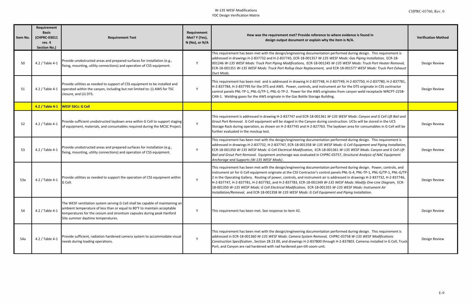
W-135 WESF ModificationsFDC Design Verification Matrix
Item No.
Requirement Basis
(CHPRC-03011 rev. 4
Section No.)
Requirement TextRequirement Met? Y (Yes),
N (No), or N/A
How was the requirement met? Provide reference to where evidence is found indesign output document or explain why the item is N/A.
Verification Method
50 4.2 / Table 4-1Provide unobstructed areas and prepared surfaces for installation (e.g., fixing, mounting, utility connections) and operation of CSS equipment.
Y
This requirement has been met with the design/engineering documentation performed during design. This requirement is addressed in drawings H-2-837732 and H-2-837745, ECR-18-001357 W-135 WESF Mods: Gas Piping Installation, ECR-18-001246 W-135 WESF Mods: Truck Port Piping Modifications, ECR-18-001245 W-135 WESF Mods: Truck Port Heater Removal, ECR-18-001351 W-135 WESF Mods: Truck Port Rollup Door Replacement, and ECR-18-001577 WESF Mods: Truck Port Exhaust Duct Mods.
Design Review
51 4.2 / Table 4-1Provide utilities as needed to support of CSS equipment to be installed and operated within the canyon, including but not limited to: (i) AWS for TSC closure, and (ii) DTS.
Y
This requirement has been met and is addressed in drawing H-2-837748, H-2-837749, H-2-837750, H-2-837780, H-2-837781, H-2-837784, H-2-837795 for the DTS and AWS. Power, controls, and instrument air for the DTS originate in CSS contractor control panels PNL-TP-1, PNL-G/TP-1, PNL-G-TP-2. Power for the AWS originates from canyon weld receptacle WRCPT-225B-CAN-1. Welding gases for the AWS originate in the Gas Bottle Storage Building.
Design Review
4.2 / Table 4-1 WESF SSCs: G Cell
52 4.2 / Table 4-1Provide sufficient unobstructed laydown area within G Cell to support staging of equipment, materials, and consumables required during the MCSC Project.
Y
This requirement is addressed in drawing H-2-837747 and ECR-18-001361 W-135 WESF Mods: Canyon and G Cell Lift Bail and Grout Port Removal. G Cell equipment will be staged in the Canyon during construction. UCSs will be stored in the UCS Storage Rack during operation, as shown on H-2-837745 and H-2-827763. The laydown area for consumables in G Cell will be further evaluated in the mockup test.
Design Review
53 4.2 / Table 4-1Provide unobstructed areas and prepared surfaces for installation (e.g., fixing, mounting, utility connections) and operation of CSS equipment.
Y
This requirement has been met with the design/engineering documentation performed during design. This requirement is addressed in drawings H-2-837732, H-2-837747, ECR-18-001358 W-135 WESF Mods: G Cell Equipment and Piping Installation, ECR-18-001350 W-135 WESF Mods: G Cell Electrical Modification, ECR-18-001361 W-135 WESF Mods: Canyon and G Cell Lift Bail and Grout Port Removal. Equipment anchorage was evaluated in CHPRC-03757, Structural Analysis of NAC Equipment Anchorage and Supports (W-135 WESF Mods) .
Design Review
53a 4.2 / Table 4-1Provide utilities as needed to support the operation of CSS equipment within G Cell.
Y
This requirement has been met with the design/engineering documentation performed during design. Power, controls, and instrument air for G Cell equipment originate at the CSS Contractor's control panels PNL-G-4, PNL-TP-1, PNL-G/TP-1, PNL-G/TP-2 in the Operating Gallery. Routing of power, controls, and instrument air is addressed in drawings H-2-837732, H-2-837746, H-2-837747, H-2-837781, H-2-837782, and H-2-837783, ECR-18-001349 W-135 WESF Mods: Modify One-Line Diagram, ECR-18-001350 W-135 WESF Mods: G Cell Electrical Modification, ECR-18-001355 W-135 WESF Mods: Instrument Air Installation/Removal, and ECR-18-001358 W-135 WESF Mods: G Cell Equipment and Piping Installation.
Design Review
54 4.2 / Table 4-1
The WESF ventilation system serving G Cell shall be capable of maintaining an ambient temperature of less than or equal to 80°F to maintain acceptable temperatures for the cesium and strontium capsules during peak Hanford Site summer daytime temperatures.
Y This requirement has been met. See response to item 42. Design Review
54a 4.2 / Table 4-1Provide sufficient, radiation hardened camera system to accommodate visual needs during loading operations.
Y
This requirement has been met with the design/engineering documentation performed during design. This requirement is addressed in ECR-18-001360 W-135 WESF Mods: Camera System Removal, CHPRC-03758 W-135 WESF Modifications Construction Specification , Section 28 23 00, and drawings H-2-837800 through H-2-837803. Cameras installed in G Cell, Truck Port, and Canyon are rad hardened with rad hardened pan-tilt-zoom unit.
Design Review
CHPRC-03760, Rev. 0
E-9
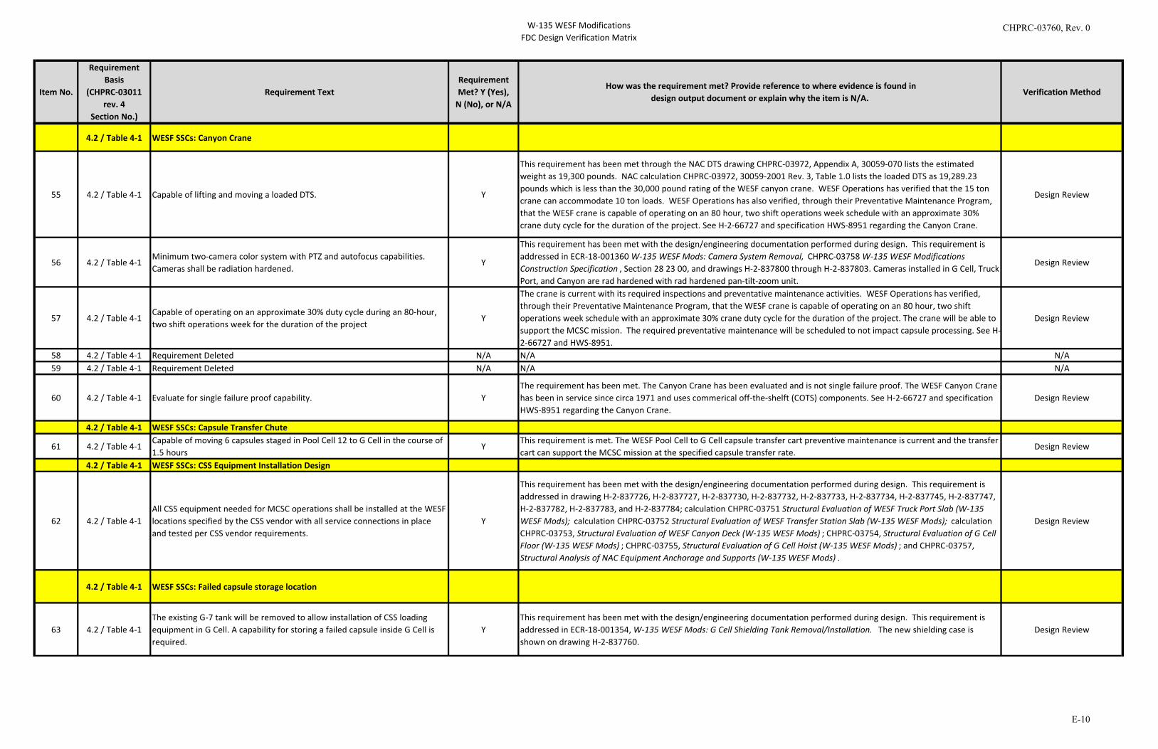
W-135 WESF ModificationsFDC Design Verification Matrix
Item No.
Requirement Basis
(CHPRC-03011 rev. 4
Section No.)
Requirement TextRequirement Met? Y (Yes),
N (No), or N/A
How was the requirement met? Provide reference to where evidence is found indesign output document or explain why the item is N/A.
Verification Method
4.2 / Table 4-1 WESF SSCs: Canyon Crane
55 4.2 / Table 4-1 Capable of lifting and moving a loaded DTS. Y
This requirement has been met through the NAC DTS drawing CHPRC-03972, Appendix A, 30059-070 lists the estimated weight as 19,300 pounds. NAC calculation CHPRC-03972, 30059-2001 Rev. 3, Table 1.0 lists the loaded DTS as 19,289.23 pounds which is less than the 30,000 pound rating of the WESF canyon crane. WESF Operations has verified that the 15 ton crane can accommodate 10 ton loads. WESF Operations has also verified, through their Preventative Maintenance Program, that the WESF crane is capable of operating on an 80 hour, two shift operations week schedule with an approximate 30% crane duty cycle for the duration of the project. See H-2-66727 and specification HWS-8951 regarding the Canyon Crane.
Design Review
56 4.2 / Table 4-1Minimum two-camera color system with PTZ and autofocus capabilities. Cameras shall be radiation hardened.
Y
This requirement has been met with the design/engineering documentation performed during design. This requirement is addressed in ECR-18-001360 W-135 WESF Mods: Camera System Removal, CHPRC-03758 W-135 WESF Modifications Construction Specification , Section 28 23 00, and drawings H-2-837800 through H-2-837803. Cameras installed in G Cell, Truck Port, and Canyon are rad hardened with rad hardened pan-tilt-zoom unit.
Design Review
57 4.2 / Table 4-1Capable of operating on an approximate 30% duty cycle during an 80-hour, two shift operations week for the duration of the project
Y
The crane is current with its required inspections and preventative maintenance activities. WESF Operations has verified, through their Preventative Maintenance Program, that the WESF crane is capable of operating on an 80 hour, two shift operations week schedule with an approximate 30% crane duty cycle for the duration of the project. The crane will be able to support the MCSC mission. The required preventative maintenance will be scheduled to not impact capsule processing. See H-2-66727 and HWS-8951.
Design Review
58 4.2 / Table 4-1 Requirement Deleted N/A N/A N/A59 4.2 / Table 4-1 Requirement Deleted N/A N/A N/A
60 4.2 / Table 4-1 Evaluate for single failure proof capability. YThe requirement has been met. The Canyon Crane has been evaluated and is not single failure proof. The WESF Canyon Crane has been in service since circa 1971 and uses commerical off-the-shelft (COTS) components. See H-2-66727 and specification HWS-8951 regarding the Canyon Crane.
Design Review
4.2 / Table 4-1 WESF SSCs: Capsule Transfer Chute
61 4.2 / Table 4-1Capable of moving 6 capsules staged in Pool Cell 12 to G Cell in the course of 1.5 hours
YThis requirement is met. The WESF Pool Cell to G Cell capsule transfer cart preventive maintenance is current and the transfer cart can support the MCSC mission at the specified capsule transfer rate.
Design Review
4.2 / Table 4-1 WESF SSCs: CSS Equipment Installation Design
62 4.2 / Table 4-1All CSS equipment needed for MCSC operations shall be installed at the WESF locations specified by the CSS vendor with all service connections in place and tested per CSS vendor requirements.
Y
This requirement has been met with the design/engineering documentation performed during design. This requirement is addressed in drawing H-2-837726, H-2-837727, H-2-837730, H-2-837732, H-2-837733, H-2-837734, H-2-837745, H-2-837747, H-2-837782, H-2-837783, and H-2-837784; calculation CHPRC-03751 Structural Evaluation of WESF Truck Port Slab (W-135 WESF Mods); calculation CHPRC-03752 Structural Evaluation of WESF Transfer Station Slab (W-135 WESF Mods); calculation CHPRC-03753, Structural Evaluation of WESF Canyon Deck (W-135 WESF Mods) ; CHPRC-03754, Structural Evaluation of G Cell Floor (W-135 WESF Mods) ; CHPRC-03755, Structural Evaluation of G Cell Hoist (W-135 WESF Mods) ; and CHPRC-03757, Structural Analysis of NAC Equipment Anchorage and Supports (W-135 WESF Mods) .
Design Review
4.2 / Table 4-1 WESF SSCs: Failed capsule storage location
63 4.2 / Table 4-1The existing G-7 tank will be removed to allow installation of CSS loading equipment in G Cell. A capability for storing a failed capsule inside G Cell is required.
YThis requirement has been met with the design/engineering documentation performed during design. This requirement is addressed in ECR-18-001354, W-135 WESF Mods: G Cell Shielding Tank Removal/Installation. The new shielding case is shown on drawing H-2-837760.
Design Review
CHPRC-03760, Rev. 0
E-10
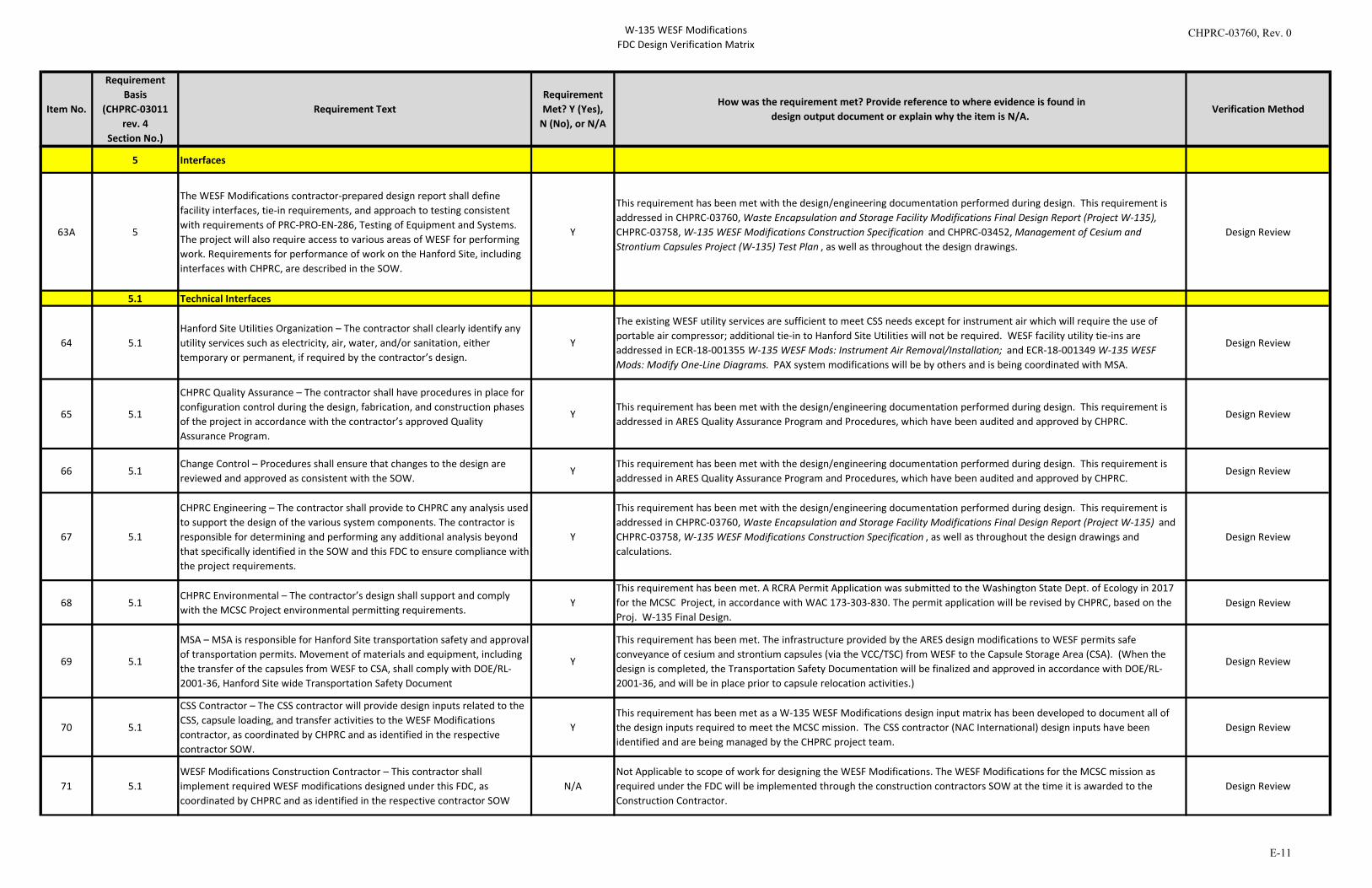
W-135 WESF ModificationsFDC Design Verification Matrix
Item No.
Requirement Basis
(CHPRC-03011 rev. 4
Section No.)
Requirement TextRequirement Met? Y (Yes),
N (No), or N/A
How was the requirement met? Provide reference to where evidence is found indesign output document or explain why the item is N/A.
Verification Method
5 Interfaces
63A 5
The WESF Modifications contractor-prepared design report shall define facility interfaces, tie-in requirements, and approach to testing consistent with requirements of PRC-PRO-EN-286, Testing of Equipment and Systems. The project will also require access to various areas of WESF for performing work. Requirements for performance of work on the Hanford Site, including interfaces with CHPRC, are described in the SOW.
Y
This requirement has been met with the design/engineering documentation performed during design. This requirement is addressed in CHPRC-03760, Waste Encapsulation and Storage Facility Modifications Final Design Report (Project W-135), CHPRC-03758, W-135 WESF Modifications Construction Specification and CHPRC-03452, Management of Cesium and Strontium Capsules Project (W-135) Test Plan , as well as throughout the design drawings.
Design Review
5.1 Technical Interfaces
64 5.1Hanford Site Utilities Organization – The contractor shall clearly identify any utility services such as electricity, air, water, and/or sanitation, either temporary or permanent, if required by the contractor’s design.
Y
The existing WESF utility services are sufficient to meet CSS needs except for instrument air which will require the use of portable air compressor; additional tie-in to Hanford Site Utilities will not be required. WESF facility utility tie-ins are addressed in ECR-18-001355 W-135 WESF Mods: Instrument Air Removal/Installation; and ECR-18-001349 W-135 WESF Mods: Modify One-Line Diagrams. PAX system modifications will be by others and is being coordinated with MSA.
Design Review
65 5.1
CHPRC Quality Assurance – The contractor shall have procedures in place for configuration control during the design, fabrication, and construction phases of the project in accordance with the contractor’s approved Quality Assurance Program.
YThis requirement has been met with the design/engineering documentation performed during design. This requirement is addressed in ARES Quality Assurance Program and Procedures, which have been audited and approved by CHPRC.
Design Review
66 5.1Change Control – Procedures shall ensure that changes to the design are reviewed and approved as consistent with the SOW.
YThis requirement has been met with the design/engineering documentation performed during design. This requirement is addressed in ARES Quality Assurance Program and Procedures, which have been audited and approved by CHPRC.
Design Review
67 5.1
CHPRC Engineering – The contractor shall provide to CHPRC any analysis used to support the design of the various system components. The contractor is responsible for determining and performing any additional analysis beyond that specifically identified in the SOW and this FDC to ensure compliance with the project requirements.
Y
This requirement has been met with the design/engineering documentation performed during design. This requirement is addressed in CHPRC-03760, Waste Encapsulation and Storage Facility Modifications Final Design Report (Project W-135) and CHPRC-03758, W-135 WESF Modifications Construction Specification , as well as throughout the design drawings and calculations.
Design Review
68 5.1CHPRC Environmental – The contractor’s design shall support and comply with the MCSC Project environmental permitting requirements.
YThis requirement has been met. A RCRA Permit Application was submitted to the Washington State Dept. of Ecology in 2017 for the MCSC Project, in accordance with WAC 173-303-830. The permit application will be revised by CHPRC, based on the Proj. W-135 Final Design.
Design Review
69 5.1
MSA – MSA is responsible for Hanford Site transportation safety and approval of transportation permits. Movement of materials and equipment, including the transfer of the capsules from WESF to CSA, shall comply with DOE/RL-2001-36, Hanford Site wide Transportation Safety Document
Y
This requirement has been met. The infrastructure provided by the ARES design modifications to WESF permits safe conveyance of cesium and strontium capsules (via the VCC/TSC) from WESF to the Capsule Storage Area (CSA). (When the design is completed, the Transportation Safety Documentation will be finalized and approved in accordance with DOE/RL-2001-36, and will be in place prior to capsule relocation activities.)
Design Review
70 5.1
CSS Contractor – The CSS contractor will provide design inputs related to the CSS, capsule loading, and transfer activities to the WESF Modifications contractor, as coordinated by CHPRC and as identified in the respective contractor SOW.
YThis requirement has been met as a W-135 WESF Modifications design input matrix has been developed to document all of the design inputs required to meet the MCSC mission. The CSS contractor (NAC International) design inputs have been identified and are being managed by the CHPRC project team.
Design Review
71 5.1WESF Modifications Construction Contractor – This contractor shall implement required WESF modifications designed under this FDC, as coordinated by CHPRC and as identified in the respective contractor SOW
N/ANot Applicable to scope of work for designing the WESF Modifications. The WESF Modifications for the MCSC mission as required under the FDC will be implemented through the construction contractors SOW at the time it is awarded to the Construction Contractor.
Design Review
CHPRC-03760, Rev. 0
E-11
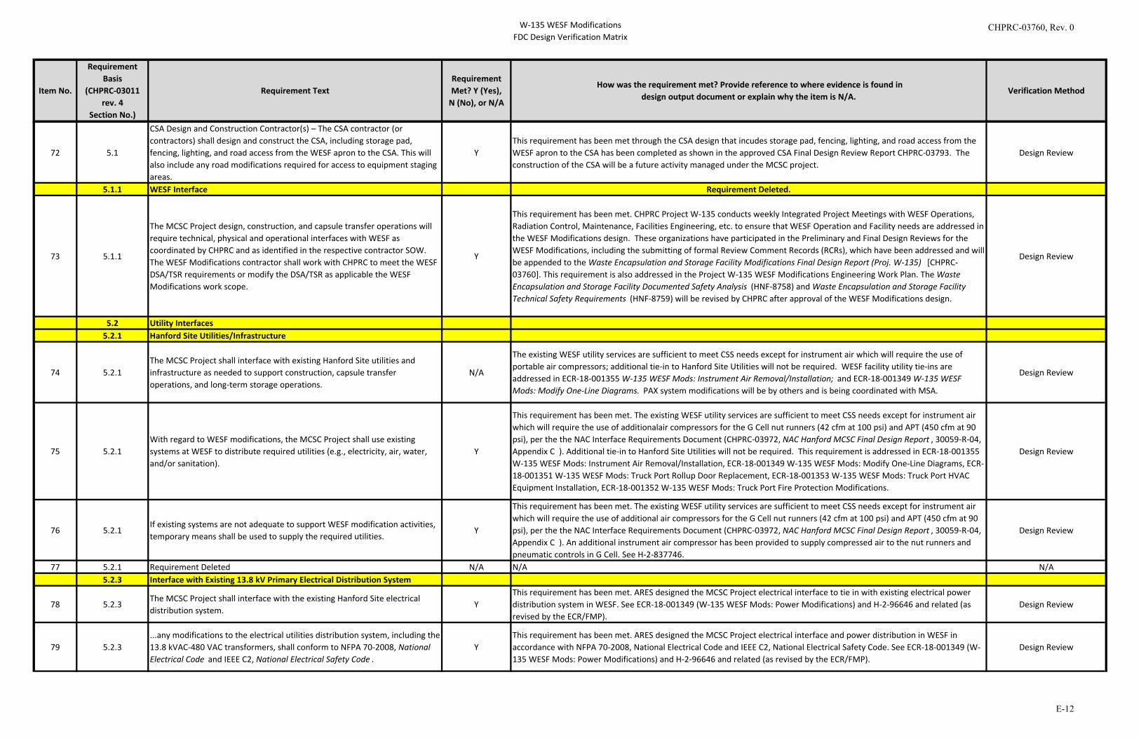
W-135 WESF ModificationsFDC Design Verification Matrix
Item No.
Requirement Basis
(CHPRC-03011 rev. 4
Section No.)
Requirement TextRequirement Met? Y (Yes),
N (No), or N/A
How was the requirement met? Provide reference to where evidence is found indesign output document or explain why the item is N/A.
Verification Method
72 5.1
CSA Design and Construction Contractor(s) – The CSA contractor (or contractors) shall design and construct the CSA, including storage pad, fencing, lighting, and road access from the WESF apron to the CSA. This will also include any road modifications required for access to equipment staging areas.
YThis requirement has been met through the CSA design that incudes storage pad, fencing, lighting, and road access from the WESF apron to the CSA has been completed as shown in the approved CSA Final Design Review Report CHPRC-03793. The construction of the CSA will be a future activity managed under the MCSC project.
Design Review
5.1.1 WESF Interface Requirement Deleted.
73 5.1.1
The MCSC Project design, construction, and capsule transfer operations will require technical, physical and operational interfaces with WESF as coordinated by CHPRC and as identified in the respective contractor SOW. The WESF Modifications contractor shall work with CHPRC to meet the WESF DSA/TSR requirements or modify the DSA/TSR as applicable the WESF Modifications work scope.
Y
This requirement has been met. CHPRC Project W-135 conducts weekly Integrated Project Meetings with WESF Operations, Radiation Control, Maintenance, Facilities Engineering, etc. to ensure that WESF Operation and Facility needs are addressed in the WESF Modifications design. These organizations have participated in the Preliminary and Final Design Reviews for the WESF Modifications, including the submitting of formal Review Comment Records (RCRs), which have been addressed and will be appended to the Waste Encapsulation and Storage Facility Modifications Final Design Report (Proj. W-135) [CHPRC-03760]. This requirement is also addressed in the Project W-135 WESF Modifications Engineering Work Plan. The Waste Encapsulation and Storage Facility Documented Safety Analysis (HNF-8758) and Waste Encapsulation and Storage Facility Technical Safety Requirements (HNF-8759) will be revised by CHPRC after approval of the WESF Modifications design.
Design Review
5.2 Utility Interfaces5.2.1 Hanford Site Utilities/Infrastructure
74 5.2.1The MCSC Project shall interface with existing Hanford Site utilities and infrastructure as needed to support construction, capsule transfer operations, and long-term storage operations.
N/A
The existing WESF utility services are sufficient to meet CSS needs except for instrument air which will require the use of portable air compressors; additional tie-in to Hanford Site Utilities will not be required. WESF facility utility tie-ins are addressed in ECR-18-001355 W-135 WESF Mods: Instrument Air Removal/Installation; and ECR-18-001349 W-135 WESF Mods: Modify One-Line Diagrams. PAX system modifications will be by others and is being coordinated with MSA.
Design Review
75 5.2.1With regard to WESF modifications, the MCSC Project shall use existing systems at WESF to distribute required utilities (e.g., electricity, air, water, and/or sanitation).
Y
This requirement has been met. The existing WESF utility services are sufficient to meet CSS needs except for instrument air which will require the use of additionalair compressors for the G Cell nut runners (42 cfm at 100 psi) and APT (450 cfm at 90 psi), per the the NAC Interface Requirements Document (CHPRC-03972, NAC Hanford MCSC Final Design Report , 30059-R-04, Appendix C ). Additional tie-in to Hanford Site Utilities will not be required. This requirement is addressed in ECR-18-001355 W-135 WESF Mods: Instrument Air Removal/Installation, ECR-18-001349 W-135 WESF Mods: Modify One-Line Diagrams, ECR-18-001351 W-135 WESF Mods: Truck Port Rollup Door Replacement, ECR-18-001353 W-135 WESF Mods: Truck Port HVAC Equipment Installation, ECR-18-001352 W-135 WESF Mods: Truck Port Fire Protection Modifications.
Design Review
76 5.2.1If existing systems are not adequate to support WESF modification activities, temporary means shall be used to supply the required utilities.
Y
This requirement has been met. The existing WESF utility services are sufficient to meet CSS needs except for instrument air which will require the use of additional air compressors for the G Cell nut runners (42 cfm at 100 psi) and APT (450 cfm at 90 psi), per the the NAC Interface Requirements Document (CHPRC-03972, NAC Hanford MCSC Final Design Report , 30059-R-04, Appendix C ). An additional instrument air compressor has been provided to supply compressed air to the nut runners and pneumatic controls in G Cell. See H-2-837746.
Design Review
77 5.2.1 Requirement Deleted N/A N/A N/A5.2.3 Interface with Existing 13.8 kV Primary Electrical Distribution System
78 5.2.3The MCSC Project shall interface with the existing Hanford Site electrical distribution system.
YThis requirement has been met. ARES designed the MCSC Project electrical interface to tie in with existing electrical power distribution system in WESF. See ECR-18-001349 (W-135 WESF Mods: Power Modifications) and H-2-96646 and related (as revised by the ECR/FMP).
Design Review
79 5.2.3...any modifications to the electrical utilities distribution system, including the 13.8 kVAC-480 VAC transformers, shall conform to NFPA 70-2008, National Electrical Code and IEEE C2, National Electrical Safety Code .
YThis requirement has been met. ARES designed the MCSC Project electrical interface and power distribution in WESF in accordance with NFPA 70-2008, National Electrical Code and IEEE C2, National Electrical Safety Code. See ECR-18-001349 (W-135 WESF Mods: Power Modifications) and H-2-96646 and related (as revised by the ECR/FMP).
Design Review
CHPRC-03760, Rev. 0
E-12
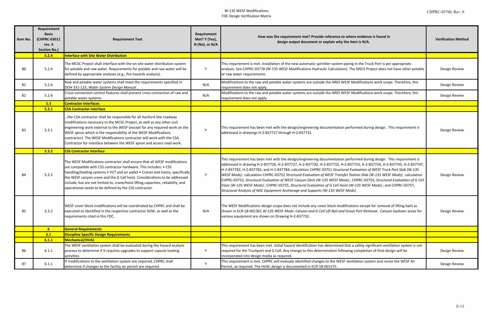
W-135 WESF ModificationsFDC Design Verification Matrix
Item No.
Requirement Basis
(CHPRC-03011 rev. 4
Section No.)
Requirement TextRequirement Met? Y (Yes),
N (No), or N/A
How was the requirement met? Provide reference to where evidence is found indesign output document or explain why the item is N/A.
Verification Method
5.2.4 Interface with Site Water Distribution
80 5.2.4The MCSC Project shall interface with the on-site water distribution system for potable and raw water. Requirements for potable and raw water will be defined by appropriate analyses (e.g., fire hazards analysis).
YThis requirement is met. Installation of the new automatic sprinkler system piping in the Truck Port is per appropriate analysis. See CHPRC-03778 (W-135 WESF Modifications Hydraulic Calculation). The MSCS Project does not have other potable or raw water requirements.
Design Review
81 5.2.4Raw and potable water systems shall meet the requirements specified in DOH 331-123, Water System Design Manual .
N/AModifications to the raw and potable water systems are outside the ARES WESF Modifications work scope. Therefore, this requirement does not apply.
Design Review
82 5.2.4Cross-connection control features shall prevent cross-connection of raw and potable water systems.
N/AModifications to the raw and potable water systems are outside the ARES WESF Modifications work scope. Therefore, this requirement does not apply.
Design Review
5.3 Contractor Interfaces5.3.1 CSA Contractor Interface
83 5.3.1
…the CSA contractor shall be responsible for all Hanford Site roadway modifications necessary to the MCSC Project, as well as any other civil engineering work external to the WESF (except for any required work on the WESF apron which is the responsibility of the WESF Modifications contractor). The WESF Modifications contractor will work with the CSA Contractor for interface between the WESF apron and access road work.
YThis requirement has been met with the design/engineering documentation performed during design. This requirement is addressed in drawings H-2-837727 through H-2-837731.
Design Review
5.3.2 CSS Contractor Interface
84 5.3.2
The WESF Modifications contractor shall ensure that all WESF modifications are compatible with CSS contractor hardware. This includes: • CSS handling/loading systems • VCT and air pallet • Cranes and hoists, specifically the WESF canyon crane and the G Cell hoist. Considerations to be addressed include, but are not limited to, crane/hoist lifting capacities, reliability, and operational needs to be defined by the CSS contractor.
Y
This requirement has been met with the design/engineering documentation performed during design. This requirement is addressed in drawing H-2-837726, H-2-837727, H-2-837730, H-2-837732, H-2-837733, H-2-837734, H-2-837745, H-2-837747, H-2-837782, H-2-837783, and H-2-837784; calculation CHPRC-03751 Structural Evaluation of WESF Truck Port Slab (W-135 WESF Mods); calculation CHPRC-03752 Structural Evaluation of WESF Transfer Station Slab (W-135 WESF Mods); calculation CHPRC-03753, Structural Evaluation of WESF Canyon Deck (W-135 WESF Mods) ; CHPRC-03754, Structural Evaluation of G Cell Floor (W-135 WESF Mods) ; CHPRC-03755, Structural Evaluation of G Cell Hoist (W-135 WESF Mods) ; and CHPRC-03757, Structural Analysis of NAC Equipment Anchorage and Supports (W-135 WESF Mods) .
Design Review
85 5.3.2WESF cover block modifications will be coordinated by CHPRC and shall be executed as identified in the respective contractor SOW, as well as the requirements cited in this FDC.
N/AThe WESF Modifications design scope does not include any cover block modifications except for removal of lifting bails as shown in ECR-18-001361 W-135 WESF Mods: Canyon and G Cell Lift Bail and Grout Port Removal. Canyon laydown areas for various equipment are shown on Drawing H-2-837732.
Design Review
6 General Requirements6.1 Discipline Specific Design Requirements
6.1.1 Mechanical/HVAC
86 6.1.1The WESF ventilation system shall be evaluated during the hazard analysis process to determine if it requires upgrades to support capsule loading activities.
YThis requirement has been met. Initial hazard identification has determined that a safety significant ventilation system is not required for the Truckport and G Cell. Any change to this determination following completion of final design will be incorporated into design media as required.
Design Review
87 6.1.1If modifications to the ventilation system are required, CHPRC shall determine if changes to the facility air permit are required.
YThis requirement is met. CHPRC will evaluate identified changes to the WESF ventilation system and revise the WESF Air Permit, as required. The HVAC design is documented in ECR-18-001575.
Design Review
CHPRC-03760, Rev. 0
E-13

W-135 WESF ModificationsFDC Design Verification Matrix
Item No.
Requirement Basis
(CHPRC-03011 rev. 4
Section No.)
Requirement TextRequirement Met? Y (Yes),
N (No), or N/A
How was the requirement met? Provide reference to where evidence is found indesign output document or explain why the item is N/A.
Verification Method
88 6.1.1
Per DOE O 420.1C, safety significant mechanical handling equipment shall meet the requirements of the codes listed in Table 6-1 below as applicable to the specific MCSC Project design.
Y
This requirement has been met. The G Cell hoist has been evaluated in CHPRC-03755, Structural Evaluation of G Cell Hoist (W-135 WESF Mods) . WESF Operations has verified that the 15 ton crane can accommodate 10 ton loads. WESF Operations has also verified, through their Preventative Maintenance Program, that the WESF crane is capable of operating on an 80 hour, two shift operations week schedule with an approximate 30% crane duty cycle for the duration of the project.
Per construction specification HWS-8951, Supplement 1, Division X, Cranes, Hoists, and Monorails, Section 8.1.j; "The 15-ton crane shall be capable of handling a load of 125 percent of rated capacity. The electric crane shall be rated for moderate service, Class C, as defined in E.O.C.I. Specification No. 61, Appendix A." The description of a moderate service Class C crane given in the E.O.C.I. Specification is "For such use as machine shops, foundries, fabricating plants, paper mill machine rooms, etc. where service requirements are medium." A more descriptive definition of a Class C (Moderate Service) crane is given in CMAA #70, section 2.4 which reads "This service covers cranes which may be used in machine shops or paper m ill machine rooms, etc., where service requirements are moderate. In this type of service, the crane will handle loads which average 50 percent of the rated capacity with 5 to 10 lifts per hour, averaging 15 feet, not over 50 percent of the lifts at rated capacity."
As noted above, the crane was designed to provide the service required by the capsule loading operations. WESF engineering has evaluated the crane's current condition and activities are scheduled to correct identified deficiencies. A robust spare parts inventory is being developed for likely components to repair. Repairs would require down time on operations, but would not create a safety concern. NAC is redesigning some components such as the shielded work platform to significantly reduce the number of crane lifts that will be required.
Design Review
89 6.1.1
All cranes, hoists, and lifting devices designed or used for activities associated with the MCSC Project shall meet the requirements of DOE-STD-1090-2011, Hoisting and Rigging, and DOE/RL-92-36, Hanford Site Hoisting and Rigging Manual.
YThis requirement has been met. The existing Canyon Crane and associated hoists meet requirements in DOE-STD-1090-2011 and are compliant with DOE/RL-92-36. The G Cell hoist has been evaluated in CHPRC-03755, Structural Evaluation of G Cell Hoist (W-135 WESF Mods) . The 15 ton crane can accommodate 10 ton loads. See H-2-66727 and specification HWS-8951.
Design Review
90 6.1.1Any required modifications to existing ventilation ductwork shall be designed to meet the following: • Ductwork shall meet the requirements of ASME AG-1, Code on Nuclear Air and Gas Treatment, Section SA
YDucting modifications have been designed to meet ASME AG-1 requirements. See AG-1 Compliance Matrix attached to CHPRC-03760, Waste Encapsulation and Storage Facility Modifications Final Design Report (Project W-135) .
Design Review
91 6.1.1• Ductwork shall meet the requirements of ASME N511, In-Service Testing of Nuclear Air Treatment, Heating, Ventilating, and Air-Conditioning Systems
Y The specified HEPA filter housing meets the requirements of ASME N511. See ASME AG-1 Compliance Matrix attached to CHPRC-03760, Waste Encapsulation and Storage Facility Modifications Final Design Report (Project W-135) .
Design Review
92 6.1.1• Ductwork shall be configured such that it does not present a tripping or bump hazard
YThis requirement has been met. See ECR-18-001575, W-135 WESF Mods: G Cell HVAC Mods, and ECR-18-001577, W-135 WESF Mods: Truck Port Exhaust Duct Mods .
Design Review
93 6.1.1• Ventilation ducts located outside of WESF above grade shall be insulated with fire-resistant materials to minimize condensation
Y The design does not include outdoor ducting. Design Review
CHPRC-03760, Rev. 0
E-14
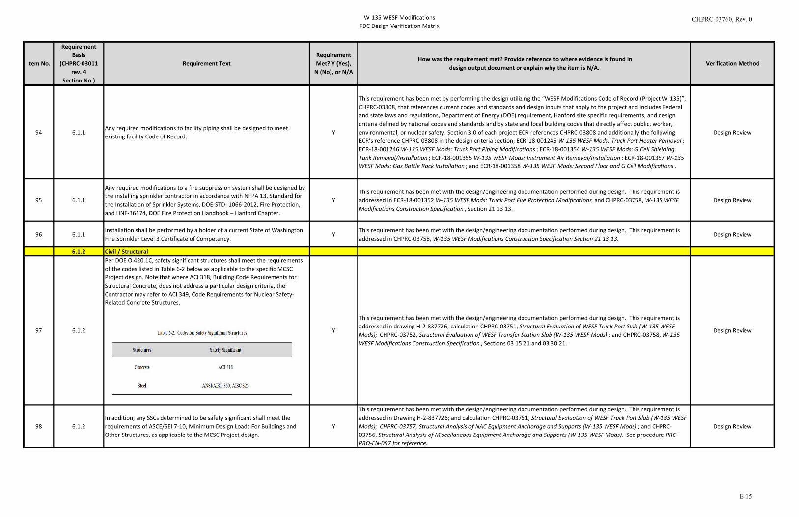
W-135 WESF ModificationsFDC Design Verification Matrix
Item No.
Requirement Basis
(CHPRC-03011 rev. 4
Section No.)
Requirement TextRequirement Met? Y (Yes),
N (No), or N/A
How was the requirement met? Provide reference to where evidence is found indesign output document or explain why the item is N/A.
Verification Method
94 6.1.1Any required modifications to facility piping shall be designed to meet existing facility Code of Record.
Y
This requirement has been met by performing the design utilizing the “WESF Modifications Code of Record (Project W-135)”, CHPRC-03808, that references current codes and standards and design inputs that apply to the project and includes Federal and state laws and regulations, Department of Energy (DOE) requirement, Hanford site specific requirements, and design criteria defined by national codes and standards and by state and local building codes that directly affect public, worker, environmental, or nuclear safety. Section 3.0 of each project ECR references CHPRC-03808 and additionally the following ECR’s reference CHPRC-03808 in the design criteria section; ECR-18-001245 W-135 WESF Mods: Truck Port Heater Removal ; ECR-18-001246 W-135 WESF Mods: Truck Port Piping Modifications ; ECR-18-001354 W-135 WESF Mods: G Cell Shielding Tank Removal/Installation ; ECR-18-001355 W-135 WESF Mods: Instrument Air Removal/Installation ; ECR-18-001357 W-135 WESF Mods: Gas Bottle Rack Installation ; and ECR-18-001358 W-135 WESF Mods: Second Floor and G Cell Modifications .
Design Review
95 6.1.1
Any required modifications to a fire suppression system shall be designed by the installing sprinkler contractor in accordance with NFPA 13, Standard for the Installation of Sprinkler Systems, DOE-STD- 1066-2012, Fire Protection, and HNF-36174, DOE Fire Protection Handbook – Hanford Chapter.
YThis requirement has been met with the design/engineering documentation performed during design. This requirement is addressed in ECR-18-001352 W-135 WESF Mods: Truck Port Fire Protection Modifications and CHPRC-03758, W-135 WESF Modifications Construction Specification , Section 21 13 13.
Design Review
96 6.1.1Installation shall be performed by a holder of a current State of Washington Fire Sprinkler Level 3 Certificate of Competency.
YThis requirement has been met with the design/engineering documentation performed during design. This requirement is addressed in CHPRC-03758, W-135 WESF Modifications Construction Specification Section 21 13 13.
Design Review
6.1.2 Civil / Structural
97 6.1.2
Per DOE O 420.1C, safety significant structures shall meet the requirements of the codes listed in Table 6-2 below as applicable to the specific MCSC Project design. Note that where ACI 318, Building Code Requirements for Structural Concrete, does not address a particular design criteria, the Contractor may refer to ACI 349, Code Requirements for Nuclear Safety-Related Concrete Structures.
Y
This requirement has been met with the design/engineering documentation performed during design. This requirement is addressed in drawing H-2-837726; calculation CHPRC-03751, Structural Evaluation of WESF Truck Port Slab (W-135 WESF Mods); CHPRC-03752, Structural Evaluation of WESF Transfer Station Slab (W-135 WESF Mods) ; and CHPRC-03758, W-135 WESF Modifications Construction Specification , Sections 03 15 21 and 03 30 21.
Design Review
98 6.1.2In addition, any SSCs determined to be safety significant shall meet the requirements of ASCE/SEI 7-10, Minimum Design Loads For Buildings and Other Structures, as applicable to the MCSC Project design.
Y
This requirement has been met with the design/engineering documentation performed during design. This requirement is addressed in Drawing H-2-837726; and calculation CHPRC-03751, Structural Evaluation of WESF Truck Port Slab (W-135 WESF Mods); CHPRC-03757, Structural Analysis of NAC Equipment Anchorage and Supports (W-135 WESF Mods) ; and CHPRC-03756, Structural Analysis of Miscellaneous Equipment Anchorage and Supports (W-135 WESF Mods). See procedure PRC-PRO-EN-097 for reference.
Design Review
CHPRC-03760, Rev. 0
E-15
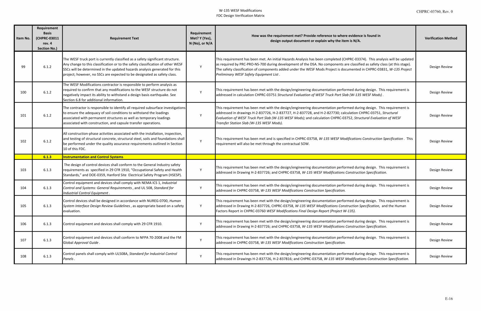
W-135 WESF ModificationsFDC Design Verification Matrix
Item No.
Requirement Basis
(CHPRC-03011 rev. 4
Section No.)
Requirement TextRequirement Met? Y (Yes),
N (No), or N/A
How was the requirement met? Provide reference to where evidence is found indesign output document or explain why the item is N/A.
Verification Method
99 6.1.2
The WESF truck port is currently classified as a safety significant structure. Any change to this classification or to the safety classification of other WESF SSCs will be determined in the updated hazards analysis generated for this project; however, no SSCs are expected to be designated as safety class.
Y
This requirement has been met. An initial Hazards Analysis has been completed (CHPRC-03374). This analysis will be updated as required by PRC-PRO-NS-700 during development of the DSA. No components are classified as safety class (at this stage). The safety classification of components added under the WESF Mods Project is documented in CHPRC-03831, W-135 Project Preliminary WESF Safety Equipment List .
Design Review
100 6.1.2
The WESF Modifications contractor is responsible to perform analysis as required to confirm that any modifications to the WESF structure do not negatively impact its ability to withstand a design basis earthquake. See Section 6.8 for additional information.
YThis requirement has been met with the design/engineering documentation performed during design. This requirement is addressed in calculation CHPRC-03751 Structural Evaluation of WESF Truck Port Slab (W-135 WESF Mods) .
Design Review
101 6.1.2
The contractor is responsible to identify all required subsurface investigations to ensure the adequacy of soil conditions to withstand the loadings associated with permanent structures as well as temporary loadings associated with construction, and capsule transfer operations.
Y
This requirement has been met with the design/engineering documentation performed during design. This requirement is addressed in drawings H-2-837726, H-2-837727, H-2-837728, and H-2-827730; calculation CHPRC-03751, Structural Evaluation of WESF Truck Port Slab (W-135 WESF Mods); and calculation CHPRC-03752, Structural Evaluation of WESF Transfer Station Slab (W-135 WESF Mods).
Design Review
102 6.1.2
All construction-phase activities associated with the installation, inspection, and testing of structural concrete, structural steel, soils and foundations shall be performed under the quality assurance requirements outlined in Section 10 of this FDC.
YThis requirement has been met and is specified in CHPRC-03758, W-135 WESF Modifications Construction Specification . This requirement will also be met through the contractual SOW.
Design Review
6.1.3 Instrumentation and Control Systems
103 6.1.3 The design of control devices shall conform to the General Industry safety requirements as specified in 29 CFR 1910, “Occupational Safety and Health Standards,” and DOE-0359, Hanford Site Electrical Safety Program (HSESP).
YThis requirement has been met with the design/engineering documentation performed during design. This requirement is addressed in Drawing H-2-837726; and CHPRC-03758, W-135 WESF Modifications Construction Specification.
Design Review
104 6.1.3Control equipment and devices shall comply with NEMA ICS 1, Industrial Control and Systems: General Requirements , and UL 508, Standard for Industrial Control Equipment .
YThis requirement has been met with the design/engineering documentation performed during design. This requirement is addressed in CHPRC-03758, W-135 WESF Modifications Construction Specification.
Design Review
105 6.1.3Control devices shall be designed in accordance with NUREG-0700, Human System Interface Design Review Guidelines , as appropriate based on a safety evaluation.
YThis requirement has been met with the design/engineering documentation performed during design. This requirement is addressed in Drawing H-2-837726, CHPRC-03758, W-135 WESF Modifications Construction Specification, and the Human Factors Report in CHPRC-03760 WESF Modifications Final Design Report (Project W-135).
Design Review
106 6.1.3 Control equipment and devices shall comply with 29 CFR 1910. YThis requirement has been met with the design/engineering documentation performed during design. This requirement is addressed in Drawing H-2-837726; and CHPRC-03758, W-135 WESF Modifications Construction Specification.
Design Review
107 6.1.3Control equipment and devices shall conform to NFPA 70-2008 and the FM Global Approval Guide .
YThis requirement has been met with the design/engineering documentation performed during design. This requirement is addressed in CHPRC-03758, W-135 WESF Modifications Construction Specification.
Design Review
108 6.1.3Control panels shall comply with UL508A, Standard for Industrial Control Panels .
YThis requirement has been met with the design/engineering documentation performed during design. This requirement is addressed in Drawings H-2-837726, H-2-837816; and CHPRC-03758, W-135 WESF Modifications Construction Specification.
Design Review
CHPRC-03760, Rev. 0
E-16
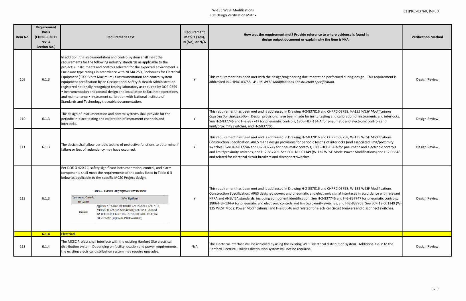
W-135 WESF ModificationsFDC Design Verification Matrix
Item No.
Requirement Basis
(CHPRC-03011 rev. 4
Section No.)
Requirement TextRequirement Met? Y (Yes),
N (No), or N/A
How was the requirement met? Provide reference to where evidence is found indesign output document or explain why the item is N/A.
Verification Method
109 6.1.3
In addition, the instrumentation and control system shall meet the requirements for the following industry standards as applicable to the project: • Instruments and controls selected for the expected environment • Enclosure type ratings in accordance with NEMA 250, Enclosures for Electrical Equipment (1000 Volts Maximum) • Instrumentation and control system equipment certification by an Occupational Safety & Health Administration-registered nationally recognized testing laboratory as required by DOE-0359 • Instrumentation and control design and installation to facilitate operations and maintenance • Instrument calibration with National Institute of Standards and Technology traceable documentation.
YThis requirement has been met with the design/engineering documentation performed during design. This requirement is addressed in CHPRC-03758, W-135 WESF Modifications Construction Specification.
Design Review
110 6.1.3The design of instrumentation and control systems shall provide for the periodic in-place testing and calibration of instrument channels and interlocks.
Y
This requirement has been met and is addressed in Drawing H-2-837816 and CHPRC-03758, W-135 WESF Modifications Construction Specification. Design provisions have been made for insitu testing and calibration of instruments and interlocks. See H-2-837746 and H-2-837747 for pneumatic controls, 1806-HEF-134-A for pneumatic and electronic controls and limit/proximity switches, and H-2-837705.
Design Review
111 6.1.3The design shall allow periodic testing of protective functions to determine if failure or loss of redundancy may have occurred.
Y
This requirement has been met and is addressed in Drawing H-2-837816 and CHPRC-03758, W-135 WESF Modifications Construction Specification. ARES made design provisions for periodic testing of interlocks (and associated limit/proximity switches). See H-2-837746 and H-2-837747 for pneumatic controls, 1806-HEF-134-A for pneumatic and electronic controls and limit/proximity switches, and H-2-837705. See ECR-18-001349 (W-135 WESF Mods: Power Modifications) and H-2-96646 and related for electrical circuit breakers and disconnect switches.
Design Review
112 6.1.3
Per DOE O 420.1C, safety significant instrumentation, control, and alarm components shall meet the requirements of the codes listed in Table 6-3 below as applicable to the specific MCSC Project design.
Y
This requirement has been met and is addressed in Drawing H-2-837816 and CHPRC-03758, W-135 WESF Modifications Construction Specification. ARES designed power, and pneumatic and electronic signal interfaces in accordance with relevant NFPA and ANSI/ISA standards, including component identification. See H-2-837746 and H-2-837747 for pneumatic controls, 1806-HEF-134-A for pneumatic and electronic controls and limit/proximity switches, and H-2-837705. See ECR-18-001349 (W-135 WESF Mods: Power Modifications) and H-2-96646 and related for electrical circuit breakers and disconnect switches.
Design Review
6.1.4 Electrical
113 6.1.4The MCSC Project shall interface with the existing Hanford Site electrical distribution system. Depending on facility location and power requirements, the existing electrical distribution system may require upgrades.
N/AThe electrical interface will be achieved by using the existing WESF electrical distribution system. Additional tie-in to the Hanford Electrical Utilities distribution system will not be required.
Design Review
CHPRC-03760, Rev. 0
E-17
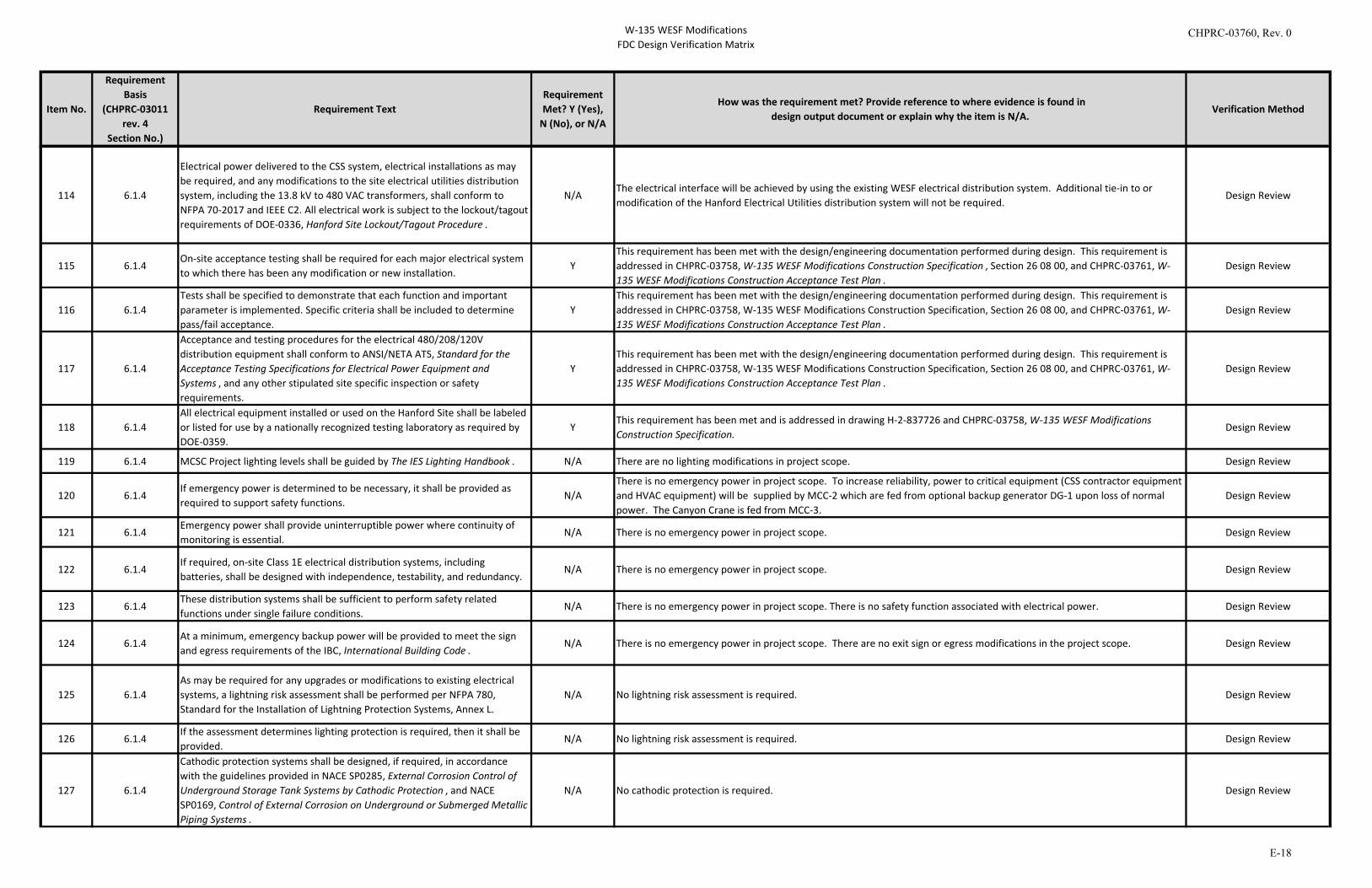
W-135 WESF ModificationsFDC Design Verification Matrix
Item No.
Requirement Basis
(CHPRC-03011 rev. 4
Section No.)
Requirement TextRequirement Met? Y (Yes),
N (No), or N/A
How was the requirement met? Provide reference to where evidence is found indesign output document or explain why the item is N/A.
Verification Method
114 6.1.4
Electrical power delivered to the CSS system, electrical installations as may be required, and any modifications to the site electrical utilities distribution system, including the 13.8 kV to 480 VAC transformers, shall conform to NFPA 70-2017 and IEEE C2. All electrical work is subject to the lockout/tagout requirements of DOE-0336, Hanford Site Lockout/Tagout Procedure .
N/AThe electrical interface will be achieved by using the existing WESF electrical distribution system. Additional tie-in to or modification of the Hanford Electrical Utilities distribution system will not be required.
Design Review
115 6.1.4On-site acceptance testing shall be required for each major electrical system to which there has been any modification or new installation.
YThis requirement has been met with the design/engineering documentation performed during design. This requirement is addressed in CHPRC-03758, W-135 WESF Modifications Construction Specification , Section 26 08 00, and CHPRC-03761, W-135 WESF Modifications Construction Acceptance Test Plan .
Design Review
116 6.1.4Tests shall be specified to demonstrate that each function and important parameter is implemented. Specific criteria shall be included to determine pass/fail acceptance.
YThis requirement has been met with the design/engineering documentation performed during design. This requirement is addressed in CHPRC-03758, W-135 WESF Modifications Construction Specification, Section 26 08 00, and CHPRC-03761, W-135 WESF Modifications Construction Acceptance Test Plan .
Design Review
117 6.1.4
Acceptance and testing procedures for the electrical 480/208/120V distribution equipment shall conform to ANSI/NETA ATS, Standard for the Acceptance Testing Specifications for Electrical Power Equipment and Systems , and any other stipulated site specific inspection or safety requirements.
YThis requirement has been met with the design/engineering documentation performed during design. This requirement is addressed in CHPRC-03758, W-135 WESF Modifications Construction Specification, Section 26 08 00, and CHPRC-03761, W-135 WESF Modifications Construction Acceptance Test Plan .
Design Review
118 6.1.4All electrical equipment installed or used on the Hanford Site shall be labeled or listed for use by a nationally recognized testing laboratory as required by DOE-0359.
YThis requirement has been met and is addressed in drawing H-2-837726 and CHPRC-03758, W-135 WESF Modifications Construction Specification.
Design Review
119 6.1.4 MCSC Project lighting levels shall be guided by The IES Lighting Handbook . N/A There are no lighting modifications in project scope. Design Review
120 6.1.4If emergency power is determined to be necessary, it shall be provided as required to support safety functions.
N/AThere is no emergency power in project scope. To increase reliability, power to critical equipment (CSS contractor equipment and HVAC equipment) will be supplied by MCC-2 which are fed from optional backup generator DG-1 upon loss of normal power. The Canyon Crane is fed from MCC-3.
Design Review
121 6.1.4Emergency power shall provide uninterruptible power where continuity of monitoring is essential.
N/A There is no emergency power in project scope. Design Review
122 6.1.4If required, on-site Class 1E electrical distribution systems, including batteries, shall be designed with independence, testability, and redundancy.
N/A There is no emergency power in project scope. Design Review
123 6.1.4These distribution systems shall be sufficient to perform safety related functions under single failure conditions.
N/A There is no emergency power in project scope. There is no safety function associated with electrical power. Design Review
124 6.1.4At a minimum, emergency backup power will be provided to meet the sign and egress requirements of the IBC, International Building Code .
N/A There is no emergency power in project scope. There are no exit sign or egress modifications in the project scope. Design Review
125 6.1.4As may be required for any upgrades or modifications to existing electrical systems, a lightning risk assessment shall be performed per NFPA 780, Standard for the Installation of Lightning Protection Systems, Annex L.
N/A No lightning risk assessment is required. Design Review
126 6.1.4If the assessment determines lighting protection is required, then it shall be provided.
N/A No lightning risk assessment is required. Design Review
127 6.1.4
Cathodic protection systems shall be designed, if required, in accordance with the guidelines provided in NACE SP0285, External Corrosion Control of Underground Storage Tank Systems by Cathodic Protection , and NACE SP0169, Control of External Corrosion on Underground or Submerged Metallic Piping Systems .
N/A No cathodic protection is required. Design Review
CHPRC-03760, Rev. 0
E-18
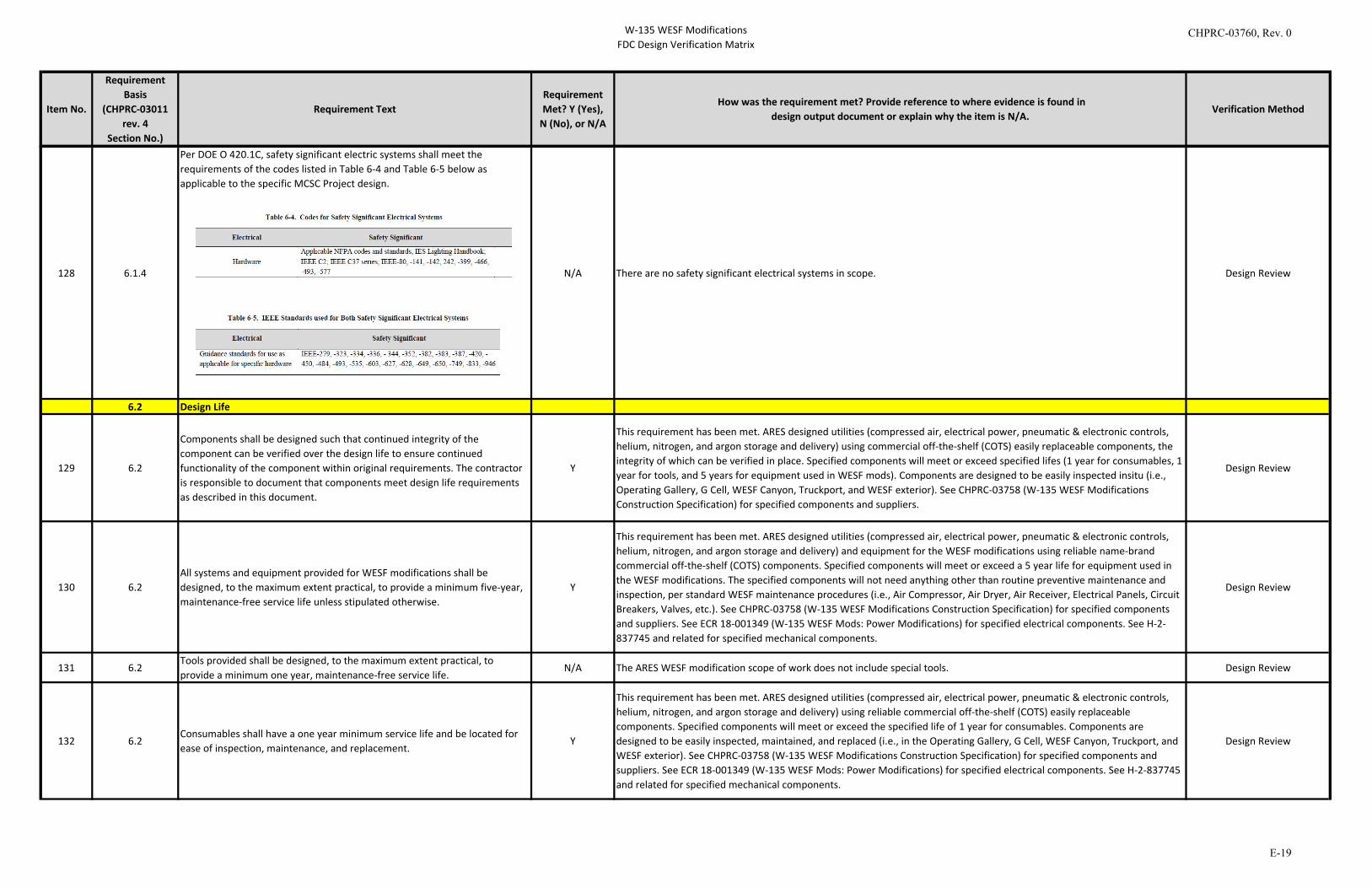
W-135 WESF ModificationsFDC Design Verification Matrix
Item No.
Requirement Basis
(CHPRC-03011 rev. 4
Section No.)
Requirement TextRequirement Met? Y (Yes),
N (No), or N/A
How was the requirement met? Provide reference to where evidence is found indesign output document or explain why the item is N/A.
Verification Method
128 6.1.4
Per DOE O 420.1C, safety significant electric systems shall meet the requirements of the codes listed in Table 6-4 and Table 6-5 below as applicable to the specific MCSC Project design.
N/A There are no safety significant electrical systems in scope. Design Review
6.2 Design Life
129 6.2
Components shall be designed such that continued integrity of the component can be verified over the design life to ensure continued functionality of the component within original requirements. The contractor is responsible to document that components meet design life requirements as described in this document.
Y
This requirement has been met. ARES designed utilities (compressed air, electrical power, pneumatic & electronic controls, helium, nitrogen, and argon storage and delivery) using commercial off-the-shelf (COTS) easily replaceable components, the integrity of which can be verified in place. Specified components will meet or exceed specified lifes (1 year for consumables, 1 year for tools, and 5 years for equipment used in WESF mods). Components are designed to be easily inspected insitu (i.e., Operating Gallery, G Cell, WESF Canyon, Truckport, and WESF exterior). See CHPRC-03758 (W-135 WESF Modifications Construction Specification) for specified components and suppliers.
Design Review
130 6.2All systems and equipment provided for WESF modifications shall be designed, to the maximum extent practical, to provide a minimum five-year, maintenance-free service life unless stipulated otherwise.
Y
This requirement has been met. ARES designed utilities (compressed air, electrical power, pneumatic & electronic controls, helium, nitrogen, and argon storage and delivery) and equipment for the WESF modifications using reliable name-brand commercial off-the-shelf (COTS) components. Specified components will meet or exceed a 5 year life for equipment used in the WESF modifications. The specified components will not need anything other than routine preventive maintenance and inspection, per standard WESF maintenance procedures (i.e., Air Compressor, Air Dryer, Air Receiver, Electrical Panels, Circuit Breakers, Valves, etc.). See CHPRC-03758 (W-135 WESF Modifications Construction Specification) for specified components and suppliers. See ECR 18-001349 (W-135 WESF Mods: Power Modifications) for specified electrical components. See H-2-837745 and related for specified mechanical components.
Design Review
131 6.2Tools provided shall be designed, to the maximum extent practical, to provide a minimum one year, maintenance-free service life.
N/A The ARES WESF modification scope of work does not include special tools. Design Review
132 6.2Consumables shall have a one year minimum service life and be located for ease of inspection, maintenance, and replacement.
Y
This requirement has been met. ARES designed utilities (compressed air, electrical power, pneumatic & electronic controls, helium, nitrogen, and argon storage and delivery) using reliable commercial off-the-shelf (COTS) easily replaceable components. Specified components will meet or exceed the specified life of 1 year for consumables. Components are designed to be easily inspected, maintained, and replaced (i.e., in the Operating Gallery, G Cell, WESF Canyon, Truckport, and WESF exterior). See CHPRC-03758 (W-135 WESF Modifications Construction Specification) for specified components and suppliers. See ECR 18-001349 (W-135 WESF Mods: Power Modifications) for specified electrical components. See H-2-837745 and related for specified mechanical components.
Design Review
CHPRC-03760, Rev. 0
E-19
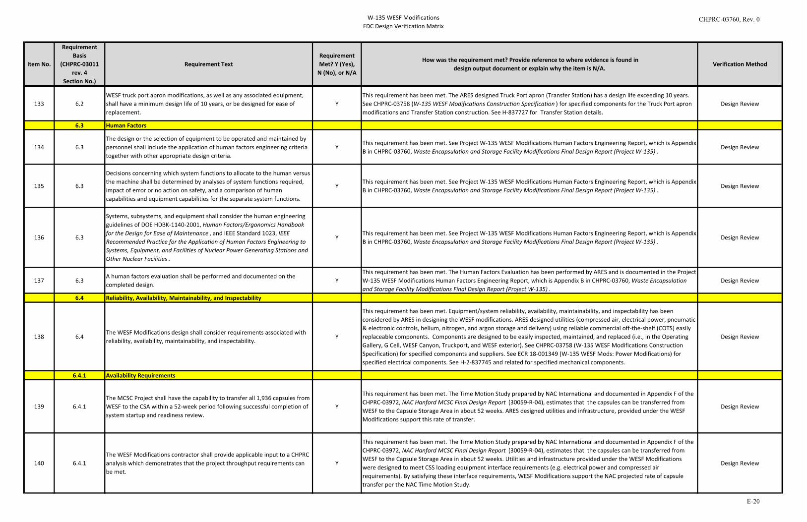
W-135 WESF ModificationsFDC Design Verification Matrix
Item No.
Requirement Basis
(CHPRC-03011 rev. 4
Section No.)
Requirement TextRequirement Met? Y (Yes),
N (No), or N/A
How was the requirement met? Provide reference to where evidence is found indesign output document or explain why the item is N/A.
Verification Method
133 6.2
WESF truck port apron modifications, as well as any associated equipment, shall have a minimum design life of 10 years, or be designed for ease of replacement.
YThis requirement has been met. The ARES designed Truck Port apron (Transfer Station) has a design life exceeding 10 years. See CHPRC-03758 (W-135 WESF Modifications Construction Specification ) for specified components for the Truck Port apron modifications and Transfer Station construction. See H-837727 for Transfer Station details.
Design Review
6.3 Human Factors
134 6.3The design or the selection of equipment to be operated and maintained by personnel shall include the application of human factors engineering criteria together with other appropriate design criteria.
YThis requirement has been met. See Project W-135 WESF Modifications Human Factors Engineering Report, which is Appendix B in CHPRC-03760, Waste Encapsulation and Storage Facility Modifications Final Design Report (Project W-135) .
Design Review
135 6.3
Decisions concerning which system functions to allocate to the human versus the machine shall be determined by analyses of system functions required, impact of error or no action on safety, and a comparison of human capabilities and equipment capabilities for the separate system functions.
YThis requirement has been met. See Project W-135 WESF Modifications Human Factors Engineering Report, which is Appendix B in CHPRC-03760, Waste Encapsulation and Storage Facility Modifications Final Design Report (Project W-135) .
Design Review
136 6.3
Systems, subsystems, and equipment shall consider the human engineering guidelines of DOE HDBK-1140-2001, Human Factors/Ergonomics Handbook for the Design for Ease of Maintenance , and IEEE Standard 1023, IEEE Recommended Practice for the Application of Human Factors Engineering to Systems, Equipment, and Facilities of Nuclear Power Generating Stations and Other Nuclear Facilities .
YThis requirement has been met. See Project W-135 WESF Modifications Human Factors Engineering Report, which is Appendix B in CHPRC-03760, Waste Encapsulation and Storage Facility Modifications Final Design Report (Project W-135) .
Design Review
137 6.3A human factors evaluation shall be performed and documented on the completed design.
YThis requirement has been met. The Human Factors Evaluation has been performed by ARES and is documented in the Project W-135 WESF Modifications Human Factors Engineering Report, which is Appendix B in CHPRC-03760, Waste Encapsulation and Storage Facility Modifications Final Design Report (Project W-135) .
Design Review
6.4 Reliability, Availability, Maintainability, and Inspectability
138 6.4The WESF Modifications design shall consider requirements associated with reliability, availability, maintainability, and inspectability.
Y
This requirement has been met. Equipment/system reliability, availability, maintainability, and inspectability has been considered by ARES in designing the WESF modifications. ARES designed utilities (compressed air, electrical power, pneumatic & electronic controls, helium, nitrogen, and argon storage and delivery) using reliable commercial off-the-shelf (COTS) easily replaceable components. Components are designed to be easily inspected, maintained, and replaced (i.e., in the Operating Gallery, G Cell, WESF Canyon, Truckport, and WESF exterior). See CHPRC-03758 (W-135 WESF Modifications Construction Specification) for specified components and suppliers. See ECR 18-001349 (W-135 WESF Mods: Power Modifications) for specified electrical components. See H-2-837745 and related for specified mechanical components.
Design Review
6.4.1 Availability Requirements
139 6.4.1The MCSC Project shall have the capability to transfer all 1,936 capsules from WESF to the CSA within a 52-week period following successful completion of system startup and readiness review.
Y
This requirement has been met. The Time Motion Study prepared by NAC International and documented in Appendix F of the CHPRC-03972, NAC Hanford MCSC Final Design Report (30059-R-04), estimates that the capsules can be transferred from WESF to the Capsule Storage Area in about 52 weeks. ARES designed utilities and infrastructure, provided under the WESF Modifications support this rate of transfer.
Design Review
140 6.4.1The WESF Modifications contractor shall provide applicable input to a CHPRC analysis which demonstrates that the project throughput requirements can be met.
Y
This requirement has been met. The Time Motion Study prepared by NAC International and documented in Appendix F of the CHPRC-03972, NAC Hanford MCSC Final Design Report (30059-R-04), estimates that the capsules can be transferred from WESF to the Capsule Storage Area in about 52 weeks. Utilities and infrastructure provided under the WESF Modifications were designed to meet CSS loading equipment interface requirements (e.g. electrical power and compressed air requirements). By satisfying these interface requirements, WESF Modifications support the NAC projected rate of capsule transfer per the NAC Time Motion Study.
Design Review
CHPRC-03760, Rev. 0
E-20
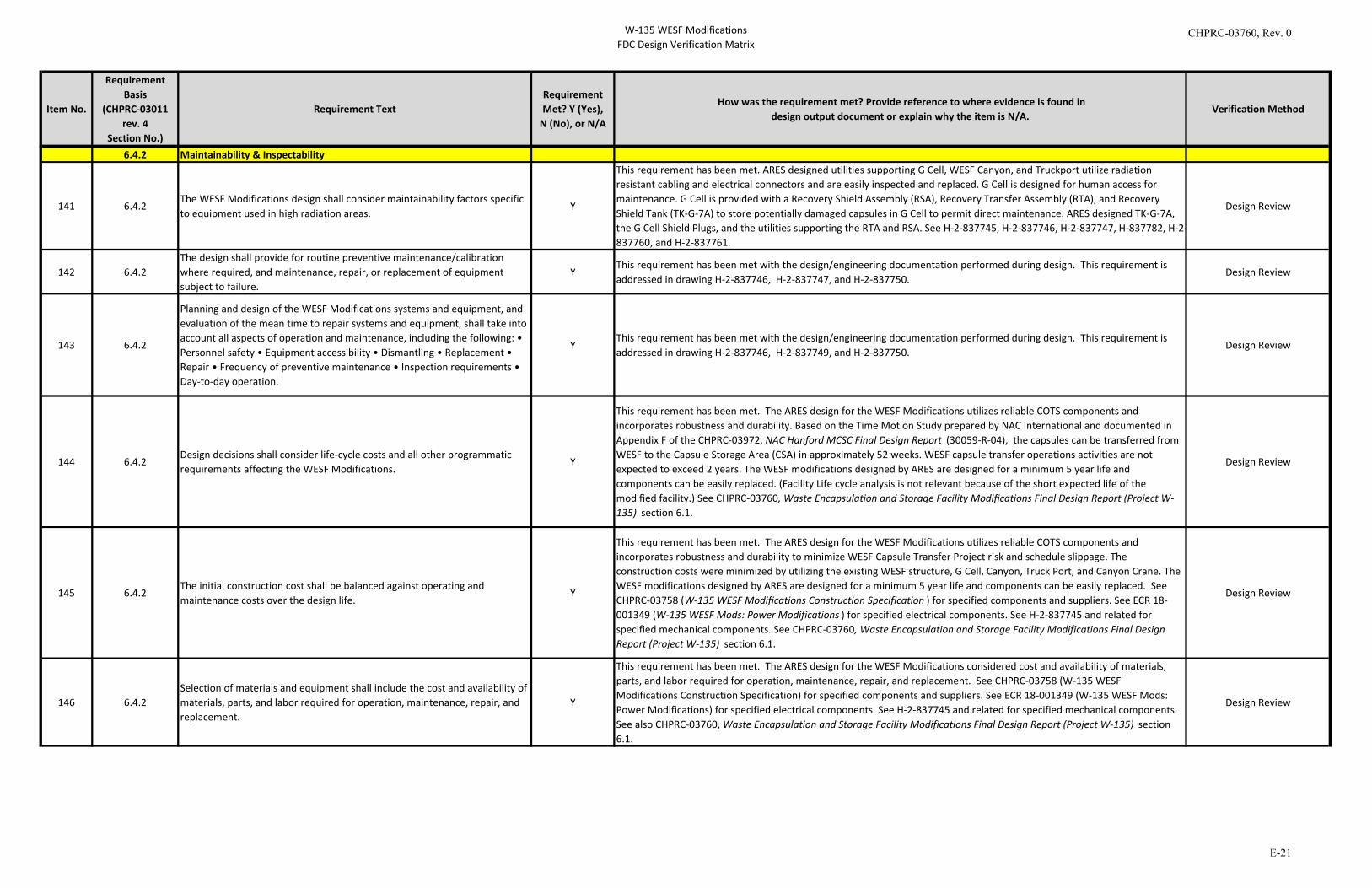
W-135 WESF ModificationsFDC Design Verification Matrix
Item No.
Requirement Basis
(CHPRC-03011 rev. 4
Section No.)
Requirement TextRequirement Met? Y (Yes),
N (No), or N/A
How was the requirement met? Provide reference to where evidence is found indesign output document or explain why the item is N/A.
Verification Method
6.4.2 Maintainability & Inspectability
141 6.4.2The WESF Modifications design shall consider maintainability factors specific to equipment used in high radiation areas.
Y
This requirement has been met. ARES designed utilities supporting G Cell, WESF Canyon, and Truckport utilize radiation resistant cabling and electrical connectors and are easily inspected and replaced. G Cell is designed for human access for maintenance. G Cell is provided with a Recovery Shield Assembly (RSA), Recovery Transfer Assembly (RTA), and Recovery Shield Tank (TK-G-7A) to store potentially damaged capsules in G Cell to permit direct maintenance. ARES designed TK-G-7A, the G Cell Shield Plugs, and the utilities supporting the RTA and RSA. See H-2-837745, H-2-837746, H-2-837747, H-837782, H-2-837760, and H-2-837761.
Design Review
142 6.4.2The design shall provide for routine preventive maintenance/calibration where required, and maintenance, repair, or replacement of equipment subject to failure.
YThis requirement has been met with the design/engineering documentation performed during design. This requirement is addressed in drawing H-2-837746, H-2-837747, and H-2-837750.
Design Review
143 6.4.2
Planning and design of the WESF Modifications systems and equipment, and evaluation of the mean time to repair systems and equipment, shall take into account all aspects of operation and maintenance, including the following: • Personnel safety • Equipment accessibility • Dismantling • Replacement • Repair • Frequency of preventive maintenance • Inspection requirements • Day-to-day operation.
YThis requirement has been met with the design/engineering documentation performed during design. This requirement is addressed in drawing H-2-837746, H-2-837749, and H-2-837750.
Design Review
144 6.4.2Design decisions shall consider life-cycle costs and all other programmatic requirements affecting the WESF Modifications.
Y
This requirement has been met. The ARES design for the WESF Modifications utilizes reliable COTS components and incorporates robustness and durability. Based on the Time Motion Study prepared by NAC International and documented in Appendix F of the CHPRC-03972, NAC Hanford MCSC Final Design Report (30059-R-04), the capsules can be transferred from WESF to the Capsule Storage Area (CSA) in approximately 52 weeks. WESF capsule transfer operations activities are not expected to exceed 2 years. The WESF modifications designed by ARES are designed for a minimum 5 year life and components can be easily replaced. (Facility Life cycle analysis is not relevant because of the short expected life of the modified facility.) See CHPRC-03760, Waste Encapsulation and Storage Facility Modifications Final Design Report (Project W-135) section 6.1.
Design Review
145 6.4.2The initial construction cost shall be balanced against operating and maintenance costs over the design life.
Y
This requirement has been met. The ARES design for the WESF Modifications utilizes reliable COTS components and incorporates robustness and durability to minimize WESF Capsule Transfer Project risk and schedule slippage. The construction costs were minimized by utilizing the existing WESF structure, G Cell, Canyon, Truck Port, and Canyon Crane. The WESF modifications designed by ARES are designed for a minimum 5 year life and components can be easily replaced. See CHPRC-03758 (W-135 WESF Modifications Construction Specification ) for specified components and suppliers. See ECR 18-001349 (W-135 WESF Mods: Power Modifications ) for specified electrical components. See H-2-837745 and related for specified mechanical components. See CHPRC-03760, Waste Encapsulation and Storage Facility Modifications Final Design Report (Project W-135) section 6.1.
Design Review
146 6.4.2Selection of materials and equipment shall include the cost and availability of materials, parts, and labor required for operation, maintenance, repair, and replacement.
Y
This requirement has been met. The ARES design for the WESF Modifications considered cost and availability of materials, parts, and labor required for operation, maintenance, repair, and replacement. See CHPRC-03758 (W-135 WESF Modifications Construction Specification) for specified components and suppliers. See ECR 18-001349 (W-135 WESF Mods: Power Modifications) for specified electrical components. See H-2-837745 and related for specified mechanical components. See also CHPRC-03760, Waste Encapsulation and Storage Facility Modifications Final Design Report (Project W-135) section 6.1.
Design Review
CHPRC-03760, Rev. 0
E-21
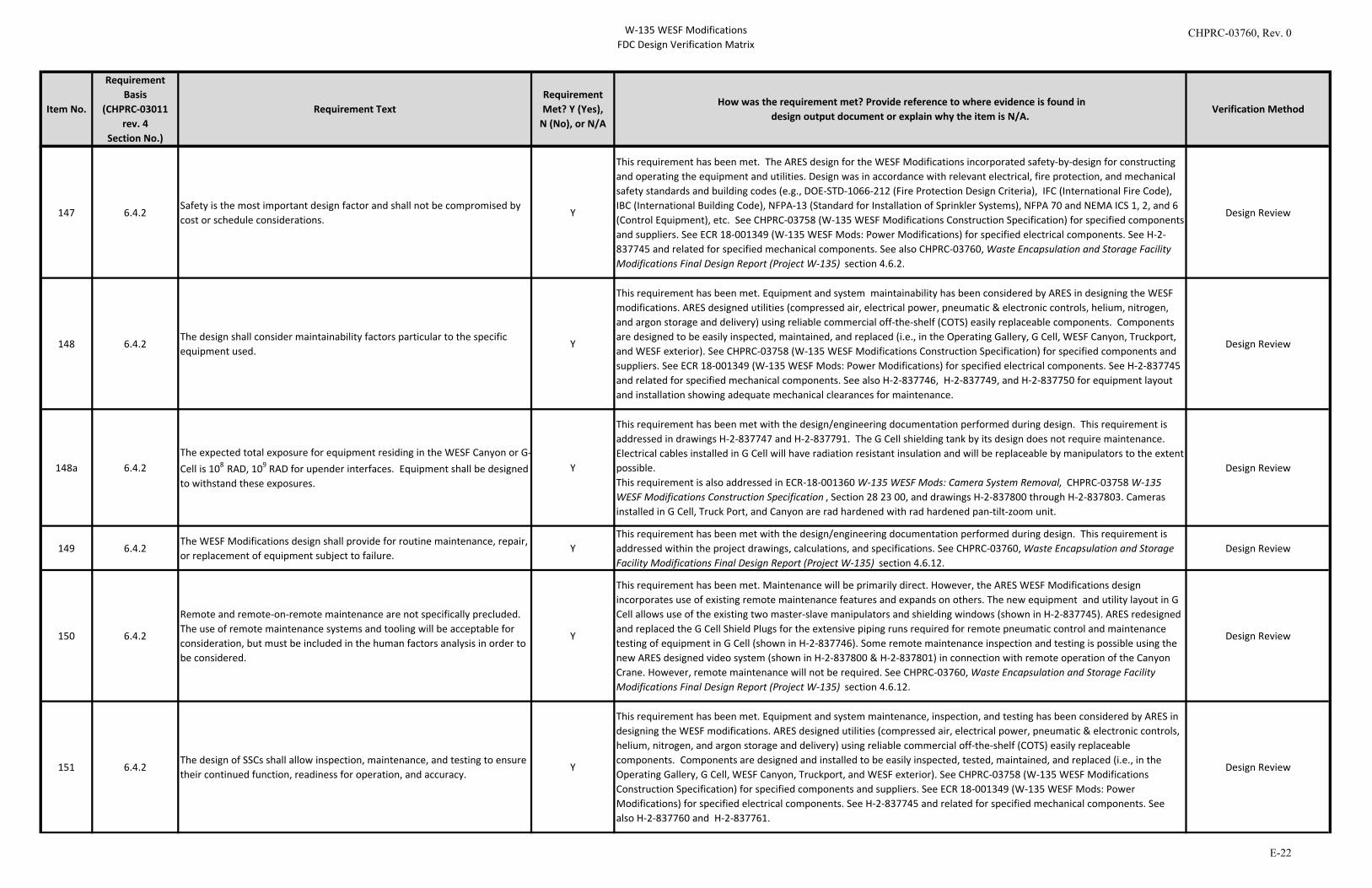
W-135 WESF ModificationsFDC Design Verification Matrix
Item No.
Requirement Basis
(CHPRC-03011 rev. 4
Section No.)
Requirement TextRequirement Met? Y (Yes),
N (No), or N/A
How was the requirement met? Provide reference to where evidence is found indesign output document or explain why the item is N/A.
Verification Method
147 6.4.2Safety is the most important design factor and shall not be compromised by cost or schedule considerations.
Y
This requirement has been met. The ARES design for the WESF Modifications incorporated safety-by-design for constructing and operating the equipment and utilities. Design was in accordance with relevant electrical, fire protection, and mechanical safety standards and building codes (e.g., DOE-STD-1066-212 (Fire Protection Design Criteria), IFC (International Fire Code), IBC (International Building Code), NFPA-13 (Standard for Installation of Sprinkler Systems), NFPA 70 and NEMA ICS 1, 2, and 6 (Control Equipment), etc. See CHPRC-03758 (W-135 WESF Modifications Construction Specification) for specified components and suppliers. See ECR 18-001349 (W-135 WESF Mods: Power Modifications) for specified electrical components. See H-2-837745 and related for specified mechanical components. See also CHPRC-03760, Waste Encapsulation and Storage Facility Modifications Final Design Report (Project W-135) section 4.6.2.
Design Review
148 6.4.2The design shall consider maintainability factors particular to the specific equipment used.
Y
This requirement has been met. Equipment and system maintainability has been considered by ARES in designing the WESF modifications. ARES designed utilities (compressed air, electrical power, pneumatic & electronic controls, helium, nitrogen, and argon storage and delivery) using reliable commercial off-the-shelf (COTS) easily replaceable components. Components are designed to be easily inspected, maintained, and replaced (i.e., in the Operating Gallery, G Cell, WESF Canyon, Truckport, and WESF exterior). See CHPRC-03758 (W-135 WESF Modifications Construction Specification) for specified components and suppliers. See ECR 18-001349 (W-135 WESF Mods: Power Modifications) for specified electrical components. See H-2-837745 and related for specified mechanical components. See also H-2-837746, H-2-837749, and H-2-837750 for equipment layout and installation showing adequate mechanical clearances for maintenance.
Design Review
148a 6.4.2The expected total exposure for equipment residing in the WESF Canyon or G-Cell is 108 RAD, 109 RAD for upender interfaces. Equipment shall be designed to withstand these exposures.
Y
This requirement has been met with the design/engineering documentation performed during design. This requirement is addressed in drawings H-2-837747 and H-2-837791. The G Cell shielding tank by its design does not require maintenance. Electrical cables installed in G Cell will have radiation resistant insulation and will be replaceable by manipulators to the extent possible.This requirement is also addressed in ECR-18-001360 W-135 WESF Mods: Camera System Removal, CHPRC-03758 W-135 WESF Modifications Construction Specification , Section 28 23 00, and drawings H-2-837800 through H-2-837803. Cameras installed in G Cell, Truck Port, and Canyon are rad hardened with rad hardened pan-tilt-zoom unit.
Design Review
149 6.4.2The WESF Modifications design shall provide for routine maintenance, repair, or replacement of equipment subject to failure.
YThis requirement has been met with the design/engineering documentation performed during design. This requirement is addressed within the project drawings, calculations, and specifications. See CHPRC-03760, Waste Encapsulation and Storage Facility Modifications Final Design Report (Project W-135) section 4.6.12.
Design Review
150 6.4.2
Remote and remote-on-remote maintenance are not specifically precluded. The use of remote maintenance systems and tooling will be acceptable for consideration, but must be included in the human factors analysis in order to be considered.
Y
This requirement has been met. Maintenance will be primarily direct. However, the ARES WESF Modifications design incorporates use of existing remote maintenance features and expands on others. The new equipment and utility layout in G Cell allows use of the existing two master-slave manipulators and shielding windows (shown in H-2-837745). ARES redesigned and replaced the G Cell Shield Plugs for the extensive piping runs required for remote pneumatic control and maintenance testing of equipment in G Cell (shown in H-2-837746). Some remote maintenance inspection and testing is possible using the new ARES designed video system (shown in H-2-837800 & H-2-837801) in connection with remote operation of the Canyon Crane. However, remote maintenance will not be required. See CHPRC-03760, Waste Encapsulation and Storage Facility Modifications Final Design Report (Project W-135) section 4.6.12.
Design Review
151 6.4.2The design of SSCs shall allow inspection, maintenance, and testing to ensure their continued function, readiness for operation, and accuracy.
Y
This requirement has been met. Equipment and system maintenance, inspection, and testing has been considered by ARES in designing the WESF modifications. ARES designed utilities (compressed air, electrical power, pneumatic & electronic controls, helium, nitrogen, and argon storage and delivery) using reliable commercial off-the-shelf (COTS) easily replaceable components. Components are designed and installed to be easily inspected, tested, maintained, and replaced (i.e., in the Operating Gallery, G Cell, WESF Canyon, Truckport, and WESF exterior). See CHPRC-03758 (W-135 WESF Modifications Construction Specification) for specified components and suppliers. See ECR 18-001349 (W-135 WESF Mods: Power Modifications) for specified electrical components. See H-2-837745 and related for specified mechanical components. See also H-2-837760 and H-2-837761.
Design Review
CHPRC-03760, Rev. 0
E-22
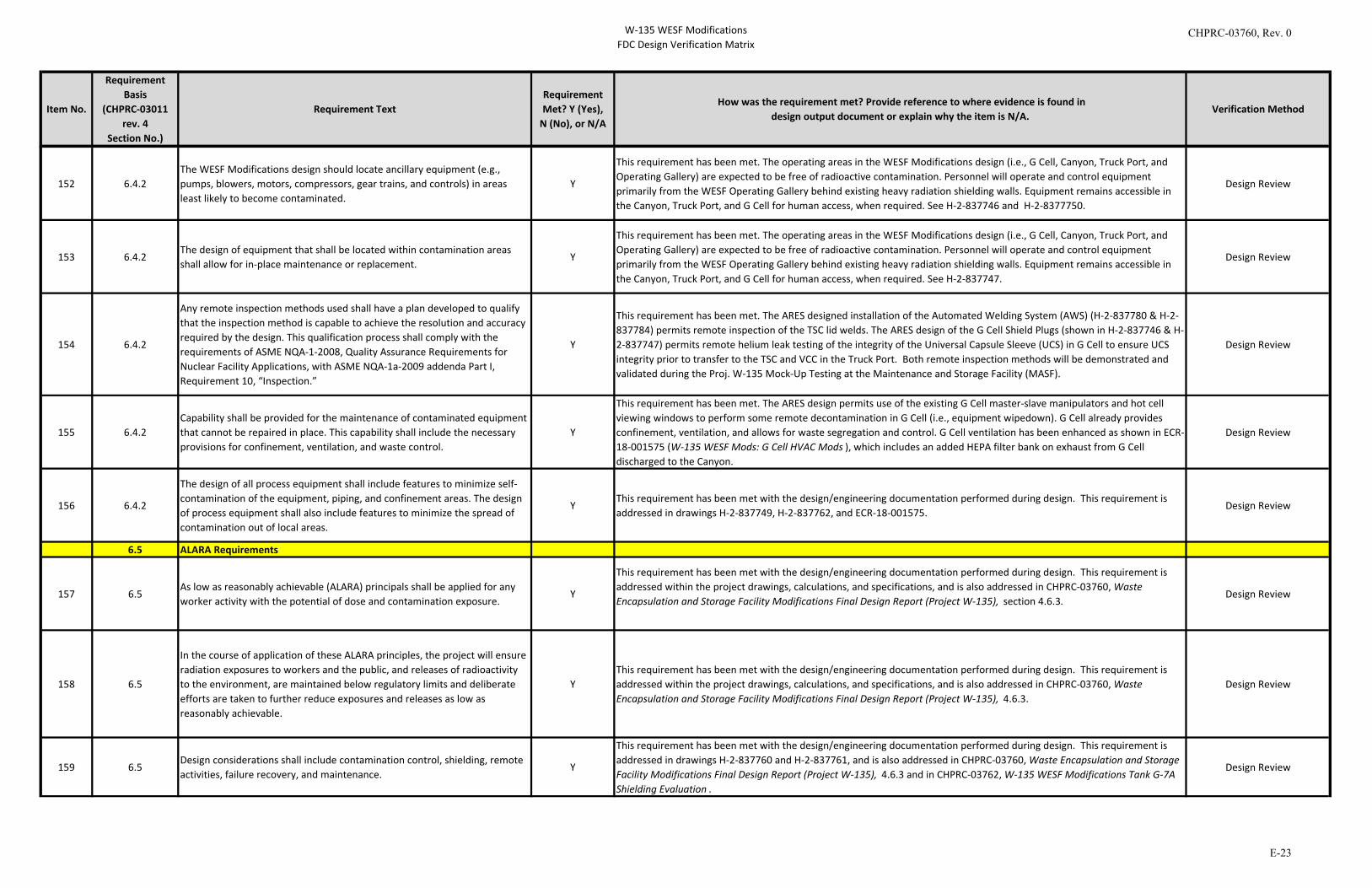
W-135 WESF ModificationsFDC Design Verification Matrix
Item No.
Requirement Basis
(CHPRC-03011 rev. 4
Section No.)
Requirement TextRequirement Met? Y (Yes),
N (No), or N/A
How was the requirement met? Provide reference to where evidence is found indesign output document or explain why the item is N/A.
Verification Method
152 6.4.2The WESF Modifications design should locate ancillary equipment (e.g., pumps, blowers, motors, compressors, gear trains, and controls) in areas least likely to become contaminated.
Y
This requirement has been met. The operating areas in the WESF Modifications design (i.e., G Cell, Canyon, Truck Port, and Operating Gallery) are expected to be free of radioactive contamination. Personnel will operate and control equipment primarily from the WESF Operating Gallery behind existing heavy radiation shielding walls. Equipment remains accessible in the Canyon, Truck Port, and G Cell for human access, when required. See H-2-837746 and H-2-8377750.
Design Review
153 6.4.2The design of equipment that shall be located within contamination areas shall allow for in-place maintenance or replacement.
Y
This requirement has been met. The operating areas in the WESF Modifications design (i.e., G Cell, Canyon, Truck Port, and Operating Gallery) are expected to be free of radioactive contamination. Personnel will operate and control equipment primarily from the WESF Operating Gallery behind existing heavy radiation shielding walls. Equipment remains accessible in the Canyon, Truck Port, and G Cell for human access, when required. See H-2-837747.
Design Review
154 6.4.2
Any remote inspection methods used shall have a plan developed to qualify that the inspection method is capable to achieve the resolution and accuracy required by the design. This qualification process shall comply with the requirements of ASME NQA-1-2008, Quality Assurance Requirements for Nuclear Facility Applications, with ASME NQA-1a-2009 addenda Part I, Requirement 10, “Inspection.”
Y
This requirement has been met. The ARES designed installation of the Automated Welding System (AWS) (H-2-837780 & H-2-837784) permits remote inspection of the TSC lid welds. The ARES design of the G Cell Shield Plugs (shown in H-2-837746 & H-2-837747) permits remote helium leak testing of the integrity of the Universal Capsule Sleeve (UCS) in G Cell to ensure UCS integrity prior to transfer to the TSC and VCC in the Truck Port. Both remote inspection methods will be demonstrated and validated during the Proj. W-135 Mock-Up Testing at the Maintenance and Storage Facility (MASF).
Design Review
155 6.4.2Capability shall be provided for the maintenance of contaminated equipment that cannot be repaired in place. This capability shall include the necessary provisions for confinement, ventilation, and waste control.
Y
This requirement has been met. The ARES design permits use of the existing G Cell master-slave manipulators and hot cell viewing windows to perform some remote decontamination in G Cell (i.e., equipment wipedown). G Cell already provides confinement, ventilation, and allows for waste segregation and control. G Cell ventilation has been enhanced as shown in ECR-18-001575 (W-135 WESF Mods: G Cell HVAC Mods ), which includes an added HEPA filter bank on exhaust from G Cell discharged to the Canyon.
Design Review
156 6.4.2
The design of all process equipment shall include features to minimize self-contamination of the equipment, piping, and confinement areas. The design of process equipment shall also include features to minimize the spread of contamination out of local areas.
YThis requirement has been met with the design/engineering documentation performed during design. This requirement is addressed in drawings H-2-837749, H-2-837762, and ECR-18-001575.
Design Review
6.5 ALARA Requirements
157 6.5As low as reasonably achievable (ALARA) principals shall be applied for any worker activity with the potential of dose and contamination exposure.
Y
This requirement has been met with the design/engineering documentation performed during design. This requirement is addressed within the project drawings, calculations, and specifications, and is also addressed in CHPRC-03760, Waste Encapsulation and Storage Facility Modifications Final Design Report (Project W-135), section 4.6.3.
Design Review
158 6.5
In the course of application of these ALARA principles, the project will ensure radiation exposures to workers and the public, and releases of radioactivity to the environment, are maintained below regulatory limits and deliberate efforts are taken to further reduce exposures and releases as low as reasonably achievable.
YThis requirement has been met with the design/engineering documentation performed during design. This requirement is addressed within the project drawings, calculations, and specifications, and is also addressed in CHPRC-03760, Waste Encapsulation and Storage Facility Modifications Final Design Report (Project W-135), 4.6.3.
Design Review
159 6.5Design considerations shall include contamination control, shielding, remote activities, failure recovery, and maintenance.
Y
This requirement has been met with the design/engineering documentation performed during design. This requirement is addressed in drawings H-2-837760 and H-2-837761, and is also addressed in CHPRC-03760, Waste Encapsulation and Storage Facility Modifications Final Design Report (Project W-135), 4.6.3 and in CHPRC-03762, W-135 WESF Modifications Tank G-7A Shielding Evaluation .
Design Review
CHPRC-03760, Rev. 0
E-23
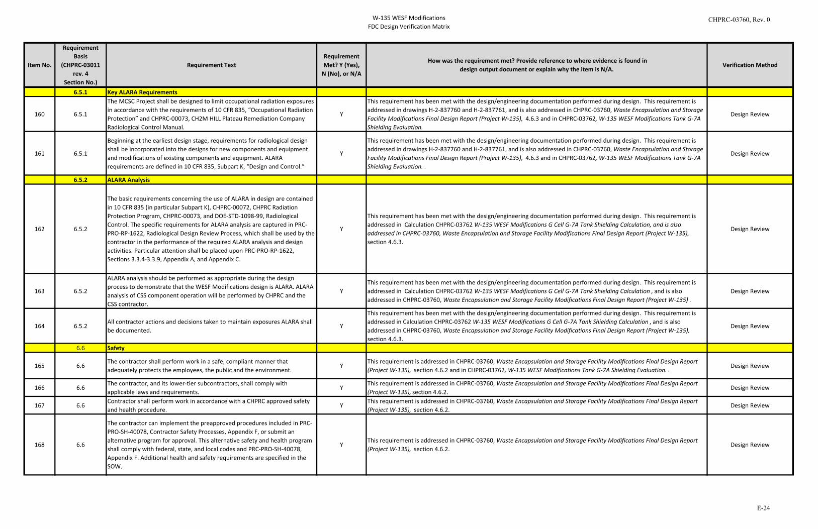
W-135 WESF ModificationsFDC Design Verification Matrix
Item No.
Requirement Basis
(CHPRC-03011 rev. 4
Section No.)
Requirement TextRequirement Met? Y (Yes),
N (No), or N/A
How was the requirement met? Provide reference to where evidence is found indesign output document or explain why the item is N/A.
Verification Method
6.5.1 Key ALARA Requirements
160 6.5.1
The MCSC Project shall be designed to limit occupational radiation exposures in accordance with the requirements of 10 CFR 835, “Occupational Radiation Protection” and CHPRC-00073, CH2M HILL Plateau Remediation Company Radiological Control Manual.
Y
This requirement has been met with the design/engineering documentation performed during design. This requirement is addressed in drawings H-2-837760 and H-2-837761, and is also addressed in CHPRC-03760, Waste Encapsulation and Storage Facility Modifications Final Design Report (Project W-135), 4.6.3 and in CHPRC-03762, W-135 WESF Modifications Tank G-7A Shielding Evaluation.
Design Review
161 6.5.1
Beginning at the earliest design stage, requirements for radiological design shall be incorporated into the designs for new components and equipment and modifications of existing components and equipment. ALARA requirements are defined in 10 CFR 835, Subpart K, “Design and Control.”
Y
This requirement has been met with the design/engineering documentation performed during design. This requirement is addressed in drawings H-2-837760 and H-2-837761, and is also addressed in CHPRC-03760, Waste Encapsulation and Storage Facility Modifications Final Design Report (Project W-135), 4.6.3 and in CHPRC-03762, W-135 WESF Modifications Tank G-7A Shielding Evaluation. .
Design Review
6.5.2 ALARA Analysis
162 6.5.2
The basic requirements concerning the use of ALARA in design are contained in 10 CFR 835 (in particular Subpart K), CHPRC-00072, CHPRC Radiation Protection Program, CHPRC-00073, and DOE-STD-1098-99, Radiological Control. The specific requirements for ALARA analysis are captured in PRC-PRO-RP-1622, Radiological Design Review Process, which shall be used by the contractor in the performance of the required ALARA analysis and design activities. Particular attention shall be placed upon PRC-PRO-RP-1622, Sections 3.3.4-3.3.9, Appendix A, and Appendix C.
Y
This requirement has been met with the design/engineering documentation performed during design. This requirement is addressed in Calculation CHPRC-03762 W-135 WESF Modifications G Cell G-7A Tank Shielding Calculation, and is also addressed in CHPRC-03760, Waste Encapsulation and Storage Facility Modifications Final Design Report (Project W-135), section 4.6.3.
Design Review
163 6.5.2
ALARA analysis should be performed as appropriate during the design process to demonstrate that the WESF Modifications design is ALARA. ALARA analysis of CSS component operation will be performed by CHPRC and the CSS contractor.
YThis requirement has been met with the design/engineering documentation performed during design. This requirement is addressed in Calculation CHPRC-03762 W-135 WESF Modifications G Cell G-7A Tank Shielding Calculation , and is also addressed in CHPRC-03760, Waste Encapsulation and Storage Facility Modifications Final Design Report (Project W-135) .
Design Review
164 6.5.2All contractor actions and decisions taken to maintain exposures ALARA shall be documented.
Y
This requirement has been met with the design/engineering documentation performed during design. This requirement is addressed in Calculation CHPRC-03762 W-135 WESF Modifications G Cell G-7A Tank Shielding Calculation , and is also addressed in CHPRC-03760, Waste Encapsulation and Storage Facility Modifications Final Design Report (Project W-135), section 4.6.3.
Design Review
6.6 Safety
165 6.6The contractor shall perform work in a safe, compliant manner that adequately protects the employees, the public and the environment.
YThis requirement is addressed in CHPRC-03760, Waste Encapsulation and Storage Facility Modifications Final Design Report (Project W-135), section 4.6.2 and in CHPRC-03762, W-135 WESF Modifications Tank G-7A Shielding Evaluation. .
Design Review
166 6.6The contractor, and its lower-tier subcontractors, shall comply with applicable laws and requirements.
YThis requirement is addressed in CHPRC-03760, Waste Encapsulation and Storage Facility Modifications Final Design Report (Project W-135), section 4.6.2.
Design Review
167 6.6Contractor shall perform work in accordance with a CHPRC approved safety and health procedure.
YThis requirement is addressed in CHPRC-03760, Waste Encapsulation and Storage Facility Modifications Final Design Report (Project W-135), section 4.6.2.
Design Review
168 6.6
The contractor can implement the preapproved procedures included in PRC-PRO-SH-40078, Contractor Safety Processes, Appendix F, or submit an alternative program for approval. This alternative safety and health program shall comply with federal, state, and local codes and PRC-PRO-SH-40078, Appendix F. Additional health and safety requirements are specified in the SOW.
YThis requirement is addressed in CHPRC-03760, Waste Encapsulation and Storage Facility Modifications Final Design Report (Project W-135), section 4.6.2.
Design Review
CHPRC-03760, Rev. 0
E-24
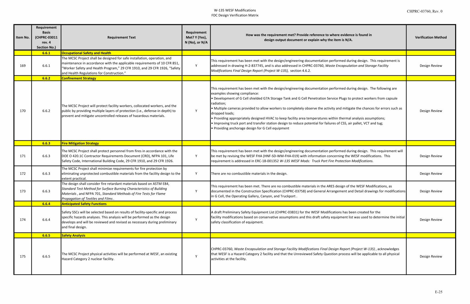
W-135 WESF ModificationsFDC Design Verification Matrix
Item No.
Requirement Basis
(CHPRC-03011 rev. 4
Section No.)
Requirement TextRequirement Met? Y (Yes),
N (No), or N/A
How was the requirement met? Provide reference to where evidence is found indesign output document or explain why the item is N/A.
Verification Method
6.6.1 Occupational Safety and Health
169 6.6.1
The MCSC Project shall be designed for safe installation, operation, and maintenance in accordance with the applicable requirements of 10 CFR 851, “Worker Safety and Health Program,” 29 CFR 1910, and 29 CFR 1926, “Safety and Health Regulations for Construction.”
YThis requirement has been met with the design/engineering documentation performed during design. This requirement is addressed in drawing H-2-837745, and is also addressed in CHPRC-03760, Waste Encapsulation and Storage Facility Modifications Final Design Report (Project W-135), section 4.6.2.
Design Review
6.6.2 Confinement Strategy
170 6.6.2The MCSC Project will protect facility workers, collocated workers, and the public by providing multiple layers of protection (i.e., defense-in depth) to prevent and mitigate uncontrolled releases of hazardous materials.
Y
This requirement has been met with the design/engineering documentation performed during design. The following are examples showing compliance: • Development of G Cell shielded G7A Storage Tank and G Cell Penetration Service Plugs to protect workers from capsule radiation; • Multiple cameras provided to allow workers to completely observe the activity and mitigate the chances for errors such as dropped loads; • Providing appropriately designed HVAC to keep facility area temperatures within thermal analysis assumptions; • Improving truck port and transfer station design to reduce potential for failures of CSS, air pallet, VCT and tug; • Providing anchorage design for G Cell equipment
Design Review
6.6.3 Fire Mitigation Strategy
171 6.6.3The MCSC Project shall protect personnel from fires in accordance with the DOE O 420.1C Contractor Requirements Document (CRD), NFPA 101, Life Safety Code, International Building Code, 29 CFR 1910, and 29 CFR 1926.
YThis requirement has been met with the design/engineering documentation performed during design. This requirement will be met by revising the WESF FHA (HNF-SD-WM-FHA-019) with information concerning the WESF modifications. This requirement is addressed in ERC-18-001352 W-135 WESF Mods: Truck Port Fire Protection Modifications.
Design Review
172 6.6.3The MCSC Project shall minimize requirements for fire protection by eliminating unprotected combustible materials from the facility design to the extent practical.
Y There are no combustible materials in the design. Design Review
173 6.6.3
The design shall consider fire retardant materials based on ASTM E84, Standard Test Method for Surface Burning Characteristics of Building Materials , and NFPA 701, Standard Methods of Fire Tests for Flame Propagation of Textiles and Films .
YThis requirement has been met. There are no combustible materials in the ARES design of the WESF Modifications, as documented in the Construction Specification (CHPRC-03758) and General Arrangement and Detail drawings for modifications in G Cell, the Operating Gallery, Canyon, and Truckport .
Design Review
6.6.4 Anticipated Safety Functions
174 6.6.4
Safety SSCs will be selected based on results of facility-specific and process specific hazards analyses. This analysis will be performed as the design develops and will be reviewed and revised as necessary during preliminary and final design.
Y
A draft Preliminary Safety Equipment List (CHPRC-03831) for the WESF Modifications has been created for thefacility modifications based on conservative assumptions and this draft safety equipment list was used to determine the initial safety classification of equipment.
Design Review
6.6.5 Safety Analysis
175 6.6.5The MCSC Project physical activities will be performed at WESF, an existing Hazard Category 2 nuclear facility.
Y
CHPRC-03760, Waste Encapsulation and Storage Facility Modifications Final Design Report (Project W-135) , acknowledges that WESF is a Hazard Category 2 facility and that the Unreviewed Safety Question process will be applicable to all physical activities at the facility.
Design Review
CHPRC-03760, Rev. 0
E-25
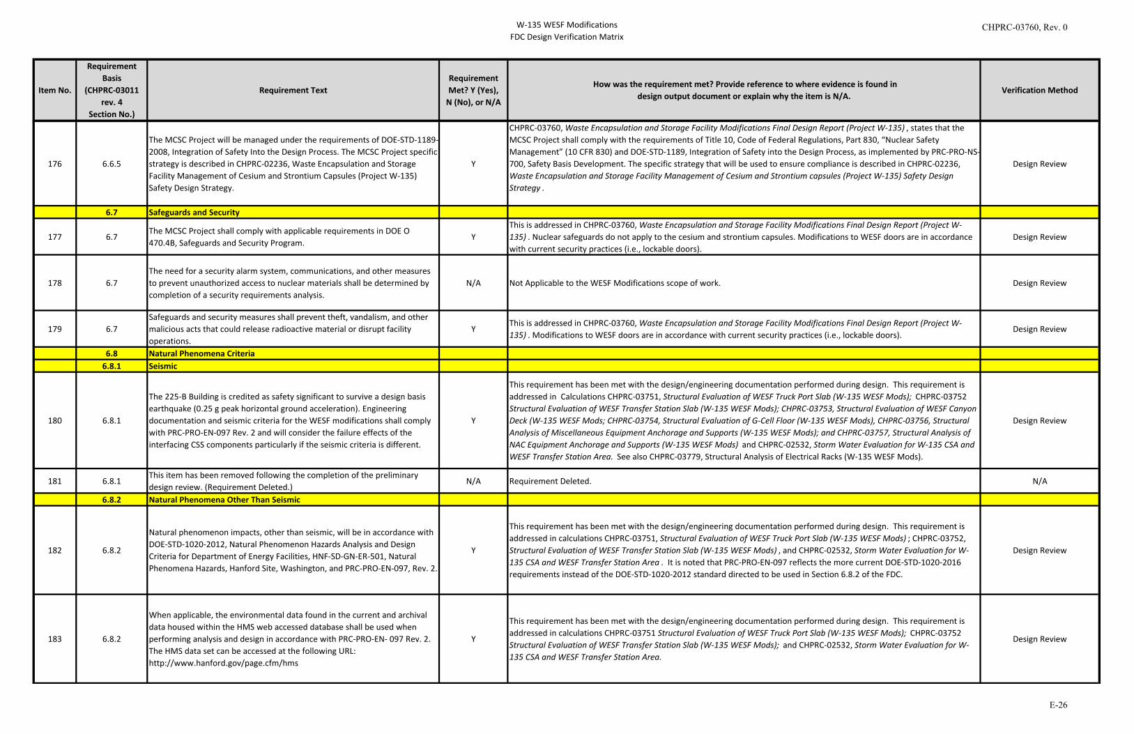
W-135 WESF ModificationsFDC Design Verification Matrix
Item No.
Requirement Basis
(CHPRC-03011 rev. 4
Section No.)
Requirement TextRequirement Met? Y (Yes),
N (No), or N/A
How was the requirement met? Provide reference to where evidence is found indesign output document or explain why the item is N/A.
Verification Method
176 6.6.5
The MCSC Project will be managed under the requirements of DOE-STD-1189-2008, Integration of Safety Into the Design Process. The MCSC Project specific strategy is described in CHPRC-02236, Waste Encapsulation and Storage Facility Management of Cesium and Strontium Capsules (Project W-135) Safety Design Strategy.
Y
CHPRC-03760, Waste Encapsulation and Storage Facility Modifications Final Design Report (Project W-135) , states that the MCSC Project shall comply with the requirements of Title 10, Code of Federal Regulations, Part 830, “Nuclear Safety Management” (10 CFR 830) and DOE-STD-1189, Integration of Safety into the Design Process, as implemented by PRC-PRO-NS-700, Safety Basis Development. The specific strategy that will be used to ensure compliance is described in CHPRC-02236, Waste Encapsulation and Storage Facility Management of Cesium and Strontium capsules (Project W-135) Safety Design Strategy .
Design Review
6.7 Safeguards and Security
177 6.7The MCSC Project shall comply with applicable requirements in DOE O 470.4B, Safeguards and Security Program.
YThis is addressed in CHPRC-03760, Waste Encapsulation and Storage Facility Modifications Final Design Report (Project W-135) . Nuclear safeguards do not apply to the cesium and strontium capsules. Modifications to WESF doors are in accordance with current security practices (i.e., lockable doors).
Design Review
178 6.7The need for a security alarm system, communications, and other measures to prevent unauthorized access to nuclear materials shall be determined by completion of a security requirements analysis.
N/A Not Applicable to the WESF Modifications scope of work. Design Review
179 6.7Safeguards and security measures shall prevent theft, vandalism, and other malicious acts that could release radioactive material or disrupt facility operations.
YThis is addressed in CHPRC-03760, Waste Encapsulation and Storage Facility Modifications Final Design Report (Project W-135) . Modifications to WESF doors are in accordance with current security practices (i.e., lockable doors).
Design Review
6.8 Natural Phenomena Criteria6.8.1 Seismic
180 6.8.1
The 225-B Building is credited as safety significant to survive a design basis earthquake (0.25 g peak horizontal ground acceleration). Engineering documentation and seismic criteria for the WESF modifications shall comply with PRC-PRO-EN-097 Rev. 2 and will consider the failure effects of the interfacing CSS components particularly if the seismic criteria is different.
Y
This requirement has been met with the design/engineering documentation performed during design. This requirement is addressed in Calculations CHPRC-03751, Structural Evaluation of WESF Truck Port Slab (W-135 WESF Mods); CHPRC-03752 Structural Evaluation of WESF Transfer Station Slab (W-135 WESF Mods); CHPRC-03753, Structural Evaluation of WESF Canyon Deck (W-135 WESF Mods; CHPRC-03754, Structural Evaluation of G-Cell Floor (W-135 WESF Mods), CHPRC-03756, Structural Analysis of Miscellaneous Equipment Anchorage and Supports (W-135 WESF Mods); and CHPRC-03757, Structural Analysis of NAC Equipment Anchorage and Supports (W-135 WESF Mods) and CHPRC-02532, Storm Water Evaluation for W-135 CSA and WESF Transfer Station Area. See also CHPRC-03779, Structural Analysis of Electrical Racks (W-135 WESF Mods).
Design Review
181 6.8.1This item has been removed following the completion of the preliminary design review. (Requirement Deleted.)
N/A Requirement Deleted. N/A
6.8.2 Natural Phenomena Other Than Seismic
182 6.8.2
Natural phenomenon impacts, other than seismic, will be in accordance with DOE-STD-1020-2012, Natural Phenomenon Hazards Analysis and Design Criteria for Department of Energy Facilities, HNF-SD-GN-ER-501, Natural Phenomena Hazards, Hanford Site, Washington, and PRC-PRO-EN-097, Rev. 2.
Y
This requirement has been met with the design/engineering documentation performed during design. This requirement is addressed in calculations CHPRC-03751, Structural Evaluation of WESF Truck Port Slab (W-135 WESF Mods) ; CHPRC-03752, Structural Evaluation of WESF Transfer Station Slab (W-135 WESF Mods) , and CHPRC-02532, Storm Water Evaluation for W-135 CSA and WESF Transfer Station Area . It is noted that PRC-PRO-EN-097 reflects the more current DOE-STD-1020-2016 requirements instead of the DOE-STD-1020-2012 standard directed to be used in Section 6.8.2 of the FDC.
Design Review
183 6.8.2
When applicable, the environmental data found in the current and archival data housed within the HMS web accessed database shall be used when performing analysis and design in accordance with PRC-PRO-EN- 097 Rev. 2. The HMS data set can be accessed at the following URL: http://www.hanford.gov/page.cfm/hms
Y
This requirement has been met with the design/engineering documentation performed during design. This requirement is addressed in calculations CHPRC-03751 Structural Evaluation of WESF Truck Port Slab (W-135 WESF Mods); CHPRC-03752 Structural Evaluation of WESF Transfer Station Slab (W-135 WESF Mods); and CHPRC-02532, Storm Water Evaluation for W-135 CSA and WESF Transfer Station Area.
Design Review
CHPRC-03760, Rev. 0
E-26
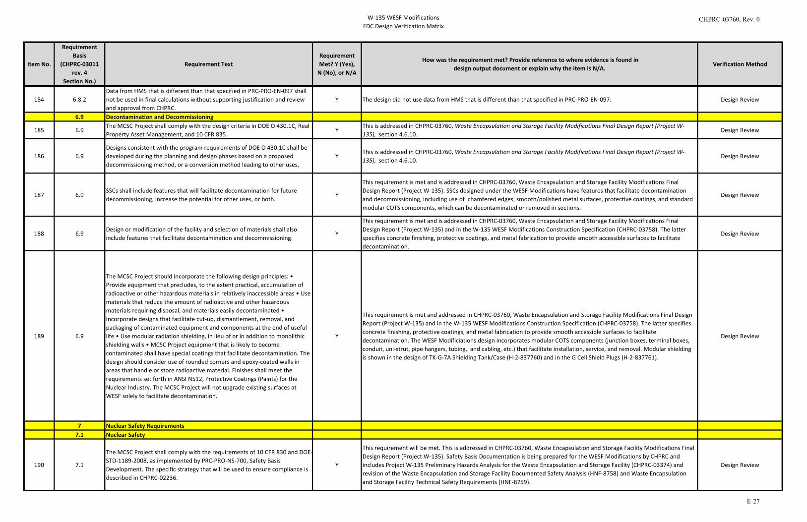
W-135 WESF ModificationsFDC Design Verification Matrix
Item No.
Requirement Basis
(CHPRC-03011 rev. 4
Section No.)
Requirement TextRequirement Met? Y (Yes),
N (No), or N/A
How was the requirement met? Provide reference to where evidence is found indesign output document or explain why the item is N/A.
Verification Method
184 6.8.2Data from HMS that is different than that specified in PRC-PRO-EN-097 shall not be used in final calculations without supporting justification and review and approval from CHPRC.
Y The design did not use data from HMS that is different than that specified in PRC-PRO-EN-097. Design Review
6.9 Decontamination and Decommissioning
185 6.9The MCSC Project shall comply with the design criteria in DOE O 430.1C, Real Property Asset Management, and 10 CFR 835.
YThis is addressed in CHPRC-03760, Waste Encapsulation and Storage Facility Modifications Final Design Report (Project W-135), section 4.6.10.
Design Review
186 6.9Designs consistent with the program requirements of DOE O 430.1C shall be developed during the planning and design phases based on a proposed decommissioning method, or a conversion method leading to other uses.
YThis is addressed in CHPRC-03760, Waste Encapsulation and Storage Facility Modifications Final Design Report (Project W-135), section 4.6.10.
Design Review
187 6.9SSCs shall include features that will facilitate decontamination for future decommissioning, increase the potential for other uses, or both.
Y
This requirement is met and is addressed in CHPRC-03760, Waste Encapsulation and Storage Facility Modifications Final Design Report (Project W-135). SSCs designed under the WESF Modifications have features that facilitate decontamination and decommissioning, including use of chamfered edges, smooth/polished metal surfaces, protective coatings, and standard modular COTS components, which can be decontaminated or removed in sections.
Design Review
188 6.9Design or modification of the facility and selection of materials shall also include features that facilitate decontamination and decommissioning.
Y
This requirement is met and is addressed in CHPRC-03760, Waste Encapsulation and Storage Facility Modifications Final Design Report (Project W-135) and in the W-135 WESF Modifications Construction Specification (CHPRC-03758). The latter specifies concrete finishing, protective coatings, and metal fabrication to provide smooth accessible surfaces to facilitate decontamination.
Design Review
189 6.9
The MCSC Project should incorporate the following design principles: • Provide equipment that precludes, to the extent practical, accumulation of radioactive or other hazardous materials in relatively inaccessible areas • Use materials that reduce the amount of radioactive and other hazardous materials requiring disposal, and materials easily decontaminated • Incorporate designs that facilitate cut-up, dismantlement, removal, and packaging of contaminated equipment and components at the end of useful life • Use modular radiation shielding, in lieu of or in addition to monolithic shielding walls • MCSC Project equipment that is likely to become contaminated shall have special coatings that facilitate decontamination. The design should consider use of rounded corners and epoxy-coated walls in areas that handle or store radioactive material. Finishes shall meet the requirements set forth in ANSI N512, Protective Coatings (Paints) for the Nuclear Industry. The MCSC Project will not upgrade existing surfaces at WESF solely to facilitate decontamination.
Y
This requirement is met and addressed in CHPRC-03760, Waste Encapsulation and Storage Facility Modifications Final Design Report (Project W-135) and in the W-135 WESF Modifications Construction Specification (CHPRC-03758). The latter specifies concrete finishing, protective coatings, and metal fabrication to provide smooth accessible surfaces to facilitate decontamination. The WESF Modificiations design incorporates modular COTS components (junction boxes, terminal boxes, conduit, uni-strut, pipe hangers, tubing, and cabling, etc.) that facilitate installation, service, and removal. Modular shielding is shown in the design of TK-G-7A Shielding Tank/Case (H-2-837760) and in the G Cell Shield Plugs (H-2-837761).
Design Review
7 Nuclear Safety Requirements 7.1 Nuclear Safety
190 7.1
The MCSC Project shall comply with the requirements of 10 CFR 830 and DOE-STD-1189-2008, as implemented by PRC-PRO-NS-700, Safety Basis Development. The specific strategy that will be used to ensure compliance is described in CHPRC-02236.
Y
This requirement will be met. This is addressed in CHPRC-03760, Waste Encapsulation and Storage Facility Modifications Final Design Report (Project W-135). Safety Basis Documentation is being prepared for the WESF Modifications by CHPRC and includes Project W-135 Preliminary Hazards Analysis for the Waste Encapsulation and Storage Facility (CHPRC-03374) and revision of the Waste Encapsulation and Storage Facility Documented Safety Analysis (HNF-8758) and Waste Encapsulation and Storage Facility Technical Safety Requirements (HNF-8759).
Design Review
CHPRC-03760, Rev. 0
E-27
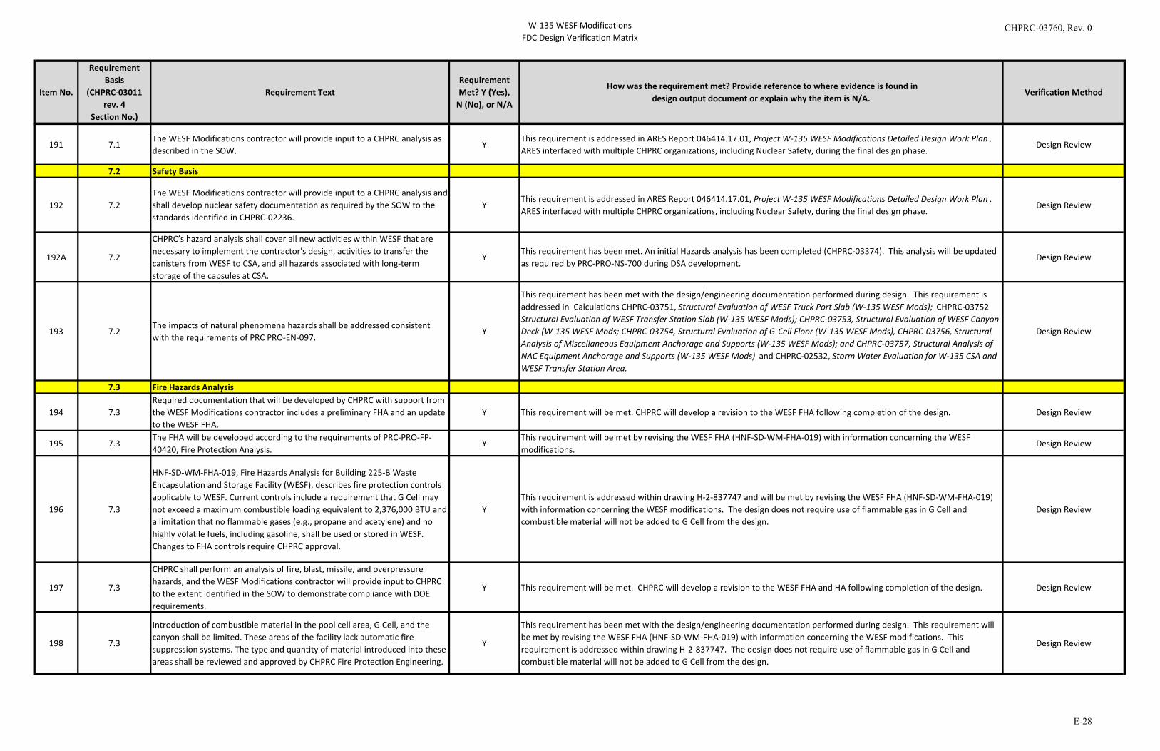
W-135 WESF ModificationsFDC Design Verification Matrix
Item No.
Requirement Basis
(CHPRC-03011 rev. 4
Section No.)
Requirement TextRequirement Met? Y (Yes),
N (No), or N/A
How was the requirement met? Provide reference to where evidence is found indesign output document or explain why the item is N/A.
Verification Method
191 7.1
The WESF Modifications contractor will provide input to a CHPRC analysis as described in the SOW.
YThis requirement is addressed in ARES Report 046414.17.01, Project W-135 WESF Modifications Detailed Design Work Plan . ARES interfaced with multiple CHPRC organizations, including Nuclear Safety, during the final design phase.
Design Review
7.2 Safety Basis
192 7.2The WESF Modifications contractor will provide input to a CHPRC analysis and shall develop nuclear safety documentation as required by the SOW to the standards identified in CHPRC-02236.
YThis requirement is addressed in ARES Report 046414.17.01, Project W-135 WESF Modifications Detailed Design Work Plan . ARES interfaced with multiple CHPRC organizations, including Nuclear Safety, during the final design phase.
Design Review
192A 7.2
CHPRC’s hazard analysis shall cover all new activities within WESF that are necessary to implement the contractor's design, activities to transfer the canisters from WESF to CSA, and all hazards associated with long-term storage of the capsules at CSA.
YThis requirement has been met. An initial Hazards analysis has been completed (CHPRC-03374). This analysis will be updated as required by PRC-PRO-NS-700 during DSA development.
Design Review
193 7.2The impacts of natural phenomena hazards shall be addressed consistent with the requirements of PRC PRO-EN-097.
Y
This requirement has been met with the design/engineering documentation performed during design. This requirement is addressed in Calculations CHPRC-03751, Structural Evaluation of WESF Truck Port Slab (W-135 WESF Mods); CHPRC-03752 Structural Evaluation of WESF Transfer Station Slab (W-135 WESF Mods); CHPRC-03753, Structural Evaluation of WESF Canyon Deck (W-135 WESF Mods; CHPRC-03754, Structural Evaluation of G-Cell Floor (W-135 WESF Mods), CHPRC-03756, Structural Analysis of Miscellaneous Equipment Anchorage and Supports (W-135 WESF Mods); and CHPRC-03757, Structural Analysis of NAC Equipment Anchorage and Supports (W-135 WESF Mods) and CHPRC-02532, Storm Water Evaluation for W-135 CSA and WESF Transfer Station Area.
Design Review
7.3 Fire Hazards Analysis
194 7.3Required documentation that will be developed by CHPRC with support from the WESF Modifications contractor includes a preliminary FHA and an update to the WESF FHA.
Y This requirement will be met. CHPRC will develop a revision to the WESF FHA following completion of the design. Design Review
195 7.3The FHA will be developed according to the requirements of PRC-PRO-FP-40420, Fire Protection Analysis.
YThis requirement will be met by revising the WESF FHA (HNF-SD-WM-FHA-019) with information concerning the WESF modifications.
Design Review
196 7.3
HNF-SD-WM-FHA-019, Fire Hazards Analysis for Building 225-B Waste Encapsulation and Storage Facility (WESF), describes fire protection controls applicable to WESF. Current controls include a requirement that G Cell may not exceed a maximum combustible loading equivalent to 2,376,000 BTU and a limitation that no flammable gases (e.g., propane and acetylene) and no highly volatile fuels, including gasoline, shall be used or stored in WESF. Changes to FHA controls require CHPRC approval.
YThis requirement is addressed within drawing H-2-837747 and will be met by revising the WESF FHA (HNF-SD-WM-FHA-019) with information concerning the WESF modifications. The design does not require use of flammable gas in G Cell and combustible material will not be added to G Cell from the design.
Design Review
197 7.3
CHPRC shall perform an analysis of fire, blast, missile, and overpressure hazards, and the WESF Modifications contractor will provide input to CHPRC to the extent identified in the SOW to demonstrate compliance with DOE requirements.
Y This requirement will be met. CHPRC will develop a revision to the WESF FHA and HA following completion of the design. Design Review
198 7.3
Introduction of combustible material in the pool cell area, G Cell, and the canyon shall be limited. These areas of the facility lack automatic fire suppression systems. The type and quantity of material introduced into these areas shall be reviewed and approved by CHPRC Fire Protection Engineering.
Y
This requirement has been met with the design/engineering documentation performed during design. This requirement will be met by revising the WESF FHA (HNF-SD-WM-FHA-019) with information concerning the WESF modifications. This requirement is addressed within drawing H-2-837747. The design does not require use of flammable gas in G Cell and combustible material will not be added to G Cell from the design.
Design Review
CHPRC-03760, Rev. 0
E-28
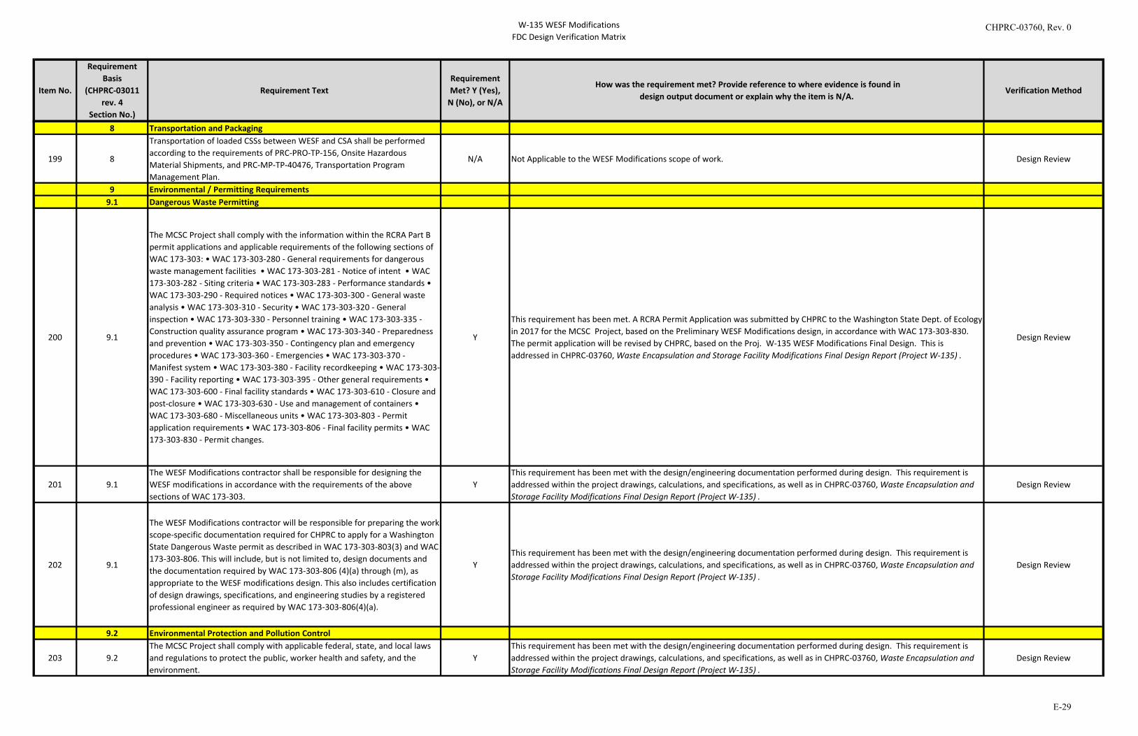
W-135 WESF ModificationsFDC Design Verification Matrix
Item No.
Requirement Basis
(CHPRC-03011 rev. 4
Section No.)
Requirement TextRequirement Met? Y (Yes),
N (No), or N/A
How was the requirement met? Provide reference to where evidence is found indesign output document or explain why the item is N/A.
Verification Method
8 Transportation and Packaging
199 8
Transportation of loaded CSSs between WESF and CSA shall be performed according to the requirements of PRC-PRO-TP-156, Onsite Hazardous Material Shipments, and PRC-MP-TP-40476, Transportation Program Management Plan.
N/A Not Applicable to the WESF Modifications scope of work. Design Review
9 Environmental / Permitting Requirements9.1 Dangerous Waste Permitting
200 9.1
The MCSC Project shall comply with the information within the RCRA Part B permit applications and applicable requirements of the following sections of WAC 173-303: • WAC 173-303-280 - General requirements for dangerous waste management facilities • WAC 173-303-281 - Notice of intent • WAC 173-303-282 - Siting criteria • WAC 173-303-283 - Performance standards • WAC 173-303-290 - Required notices • WAC 173-303-300 - General waste analysis • WAC 173-303-310 - Security • WAC 173-303-320 - General inspection • WAC 173-303-330 - Personnel training • WAC 173-303-335 - Construction quality assurance program • WAC 173-303-340 - Preparedness and prevention • WAC 173-303-350 - Contingency plan and emergency procedures • WAC 173-303-360 - Emergencies • WAC 173-303-370 - Manifest system • WAC 173-303-380 - Facility recordkeeping • WAC 173-303-390 - Facility reporting • WAC 173-303-395 - Other general requirements • WAC 173-303-600 - Final facility standards • WAC 173-303-610 - Closure and post-closure • WAC 173-303-630 - Use and management of containers • WAC 173-303-680 - Miscellaneous units • WAC 173-303-803 - Permit application requirements • WAC 173-303-806 - Final facility permits • WAC 173-303-830 - Permit changes.
Y
This requirement has been met. A RCRA Permit Application was submitted by CHPRC to the Washington State Dept. of Ecology in 2017 for the MCSC Project, based on the Preliminary WESF Modifications design, in accordance with WAC 173-303-830. The permit application will be revised by CHPRC, based on the Proj. W-135 WESF Modifications Final Design. This is addressed in CHPRC-03760, Waste Encapsulation and Storage Facility Modifications Final Design Report (Project W-135) .
Design Review
201 9.1The WESF Modifications contractor shall be responsible for designing the WESF modifications in accordance with the requirements of the above sections of WAC 173-303.
YThis requirement has been met with the design/engineering documentation performed during design. This requirement is addressed within the project drawings, calculations, and specifications, as well as in CHPRC-03760, Waste Encapsulation and Storage Facility Modifications Final Design Report (Project W-135) .
Design Review
202 9.1
The WESF Modifications contractor will be responsible for preparing the work scope-specific documentation required for CHPRC to apply for a Washington State Dangerous Waste permit as described in WAC 173-303-803(3) and WAC 173-303-806. This will include, but is not limited to, design documents and the documentation required by WAC 173-303-806 (4)(a) through (m), as appropriate to the WESF modifications design. This also includes certification of design drawings, specifications, and engineering studies by a registered professional engineer as required by WAC 173-303-806(4)(a).
YThis requirement has been met with the design/engineering documentation performed during design. This requirement is addressed within the project drawings, calculations, and specifications, as well as in CHPRC-03760, Waste Encapsulation and Storage Facility Modifications Final Design Report (Project W-135) .
Design Review
9.2 Environmental Protection and Pollution Control
203 9.2The MCSC Project shall comply with applicable federal, state, and local laws and regulations to protect the public, worker health and safety, and the environment.
YThis requirement has been met with the design/engineering documentation performed during design. This requirement is addressed within the project drawings, calculations, and specifications, as well as in CHPRC-03760, Waste Encapsulation and Storage Facility Modifications Final Design Report (Project W-135) .
Design Review
CHPRC-03760, Rev. 0
E-29
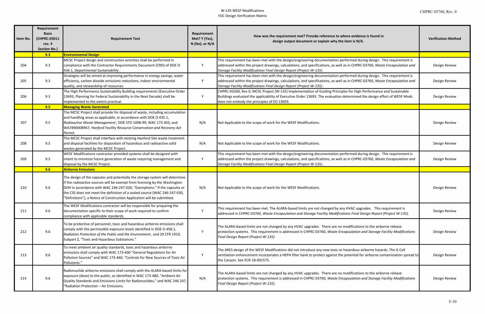
W-135 WESF ModificationsFDC Design Verification Matrix
Item No.
Requirement Basis
(CHPRC-03011 rev. 4
Section No.)
Requirement TextRequirement Met? Y (Yes),
N (No), or N/A
How was the requirement met? Provide reference to where evidence is found indesign output document or explain why the item is N/A.
Verification Method
9.3 Environmental Design
204 9.3MCSC Project design and construction activities shall be performed in compliance with the Contractor Requirements Document (CRD) of DOE O 436.1, Departmental Sustainability .
YThis requirement has been met with the design/engineering documentation performed during design. This requirement is addressed within the project drawings, calculations, and specifications, as well as in CHPRC-03760, Waste Encapsulation and Storage Facility Modifications Final Design Report (Project W-135) .
Design Review
205 9.3Strategies will be aimed at improving performance in energy savings, water efficiency, carbon dioxide emissions reductions, indoor environmental quality, and stewardship of resources.
YThis requirement has been met with the design/engineering documentation performed during design. This requirement is addressed within the project drawings, calculations, and specifications, as well as in CHPRC-03760, Waste Encapsulation and Storage Facility Modifications Final Design Report (Project W-135) .
Design Review
206 9.3The High Performance Sustainability Building requirements (Executive Order 13693, Planning for Federal Sustainability in the Next Decade) shall be implemented to the extent practical.
YCHPRC-03260, Rev 0, MCSC Project (W-135) Implementation of Guiding Principles for High Performance and Sustainable Buildings evaluated the applicability of Executive Order 13693. The evaluation determined the design effort of WESF Mods does not embody the principles of EO 13693.
Design Review
9.5 Managing Waste Generated
207 9.5
The MCSC Project shall provide for disposal of waste, including accumulation and handling areas as applicable, in accordance with DOE O 435.1, Radioactive Waste Management ; DOE STD 1098-99; WAC 173 303; and WA7890008967, Hanford Facility Resource Conservation and Recovery Act Permit.
N/A Not Applicable to the scope of work for the WESF Modifications. Design Review
208 9.5The MCSC Project shall interface with existing Hanford Site waste treatment and disposal facilities for disposition of hazardous and radioactive solid wastes generated by the MCSC Project.
N/A Not Applicable to the scope of work for the WESF Modifications. Design Review
209 9.5WESF Modifications contractor provided systems shall be designed with intent to minimize future generation of waste requiring management and disposal by the MCSC Project.
YThis requirement has been met with the design/engineering documentation performed during design. This requirement is addressed within the project drawings, calculations, and specifications, as well as in CHPRC-03760, Waste Encapsulation and Storage Facility Modifications Final Design Report (Project W-135) .
Design Review
9.6 Airborne Emissions
210 9.6
The design of the capsules and potentially the storage system will determine if the radioactive sources will be exempt from licensing by the Washington DOH in accordance with WAC 246-247-020, “Exemptions.” If the capsules or the CSS does not meet the definition of a sealed source (WAC 246-247-030, “Definitions”), a Notice of Construction Application will be submitted.
N/A Not Applicable to the scope of work for the WESF Modifications. Design Review
211 9.6The WESF Modifications contractor will be responsible for preparing the documentation specific to their scope of work required to confirm compliance with applicable standards.
YThis requirement has been met. The ALARA-based limits are not changed by any HVAC upgrades. This requirement is addressed in CHPRC-03760, Waste Encapsulation and Storage Facility Modifications Final Design Report (Project W-135).
Design Review
212 9.6
To be protective of personnel, toxic and hazardous airborne emissions shall comply with the permissible exposure levels identified in DOE O 458.1, Radiation Protection of the Public and the Environment , and 29 CFR 1910, Subpart Z, “Toxic and Hazardous Substances.”
YThe ALARA-based limits are not changed by any HVAC upgrades. There are no modifications to the airborne release protection systems. This requirement is addressed in CHPRC-03760, Waste Encapsulation and Storage Facility Modifications Final Design Report (Project W-135).
Design Review
213 9.6
To meet ambient air quality standards, toxic and hazardous airborne emissions shall comply with WAC 173-400 “General Regulations for Air Pollution Sources” and WAC 173-460, “Controls for New Sources of Toxic Air Pollutants.”
YThe ARES design of the WESF Modifications did not introduce any new toxic or hazardous airborne hazards. The G Cell ventilation enhancement incorporates a HEPA filter bank to protect against the potential for airborne contamination spread to the Canyon. See ECR-18-001575.
Design Review
214 9.6
Radionuclide airborne emissions shall comply with the ALARA-based limits for exposure (dose) to the public, as identified in WAC 173-480, “Ambient Air Quality Standards and Emissions Limits for Radionuclides,” and WAC 246 247, “Radiation Protection – Air Emissions.
N/AThe ALARA-based limits are not changed by any HVAC upgrades. There are no modifications to the airborne release protection systems. This requirement is addressed in CHPRC-03760, Waste Encapsulation and Storage Facility Modifications Final Design Report (Project W-135).
Design Review
CHPRC-03760, Rev. 0
E-30
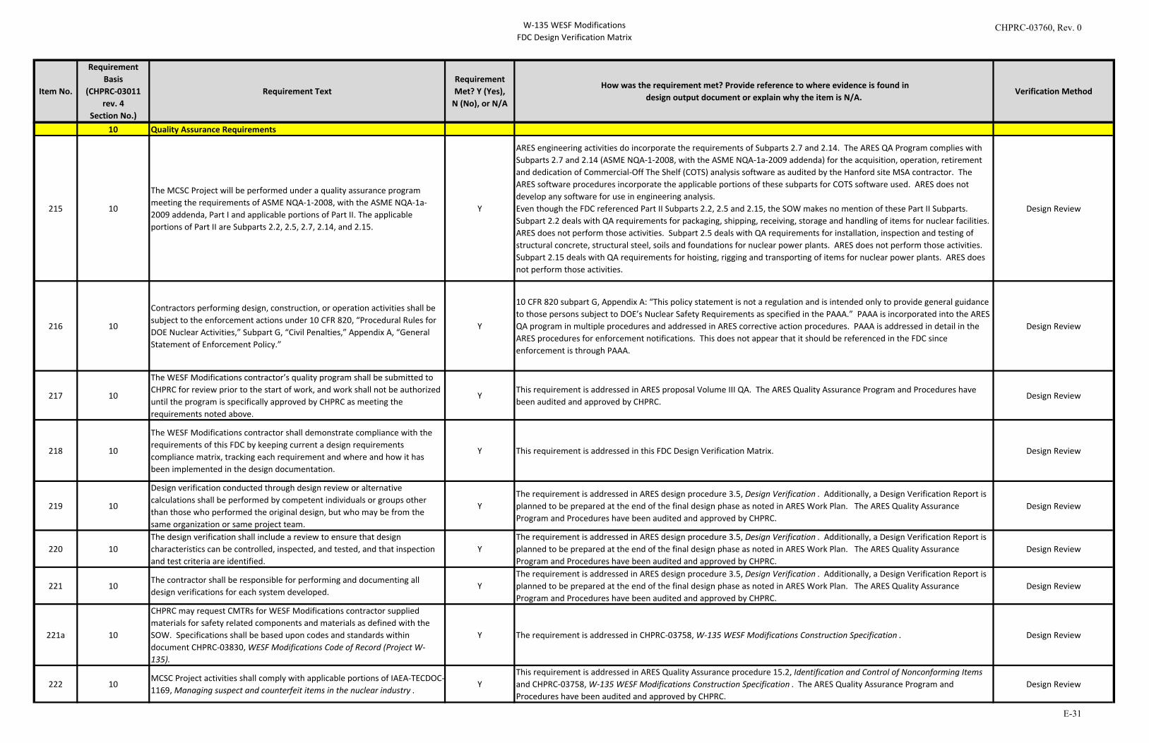
W-135 WESF ModificationsFDC Design Verification Matrix
Item No.
Requirement Basis
(CHPRC-03011 rev. 4
Section No.)
Requirement TextRequirement Met? Y (Yes),
N (No), or N/A
How was the requirement met? Provide reference to where evidence is found indesign output document or explain why the item is N/A.
Verification Method
10 Quality Assurance Requirements
215 10
The MCSC Project will be performed under a quality assurance program meeting the requirements of ASME NQA-1-2008, with the ASME NQA-1a-2009 addenda, Part I and applicable portions of Part II. The applicable portions of Part II are Subparts 2.2, 2.5, 2.7, 2.14, and 2.15.
Y
ARES engineering activities do incorporate the requirements of Subparts 2.7 and 2.14. The ARES QA Program complies with Subparts 2.7 and 2.14 (ASME NQA-1-2008, with the ASME NQA-1a-2009 addenda) for the acquisition, operation, retirement and dedication of Commercial-Off The Shelf (COTS) analysis software as audited by the Hanford site MSA contractor. The ARES software procedures incorporate the applicable portions of these subparts for COTS software used. ARES does not develop any software for use in engineering analysis.Even though the FDC referenced Part II Subparts 2.2, 2.5 and 2.15, the SOW makes no mention of these Part II Subparts. Subpart 2.2 deals with QA requirements for packaging, shipping, receiving, storage and handling of items for nuclear facilities. ARES does not perform those activities. Subpart 2.5 deals with QA requirements for installation, inspection and testing of structural concrete, structural steel, soils and foundations for nuclear power plants. ARES does not perform those activities. Subpart 2.15 deals with QA requirements for hoisting, rigging and transporting of items for nuclear power plants. ARES does not perform those activities.
Design Review
216 10
Contractors performing design, construction, or operation activities shall be subject to the enforcement actions under 10 CFR 820, “Procedural Rules for DOE Nuclear Activities,” Subpart G, “Civil Penalties,” Appendix A, “General Statement of Enforcement Policy.”
Y
10 CFR 820 subpart G, Appendix A: “This policy statement is not a regulation and is intended only to provide general guidance to those persons subject to DOE’s Nuclear Safety Requirements as specified in the PAAA.” PAAA is incorporated into the ARES QA program in multiple procedures and addressed in ARES corrective action procedures. PAAA is addressed in detail in the ARES procedures for enforcement notifications. This does not appear that it should be referenced in the FDC since enforcement is through PAAA.
Design Review
217 10
The WESF Modifications contractor’s quality program shall be submitted to CHPRC for review prior to the start of work, and work shall not be authorized until the program is specifically approved by CHPRC as meeting the requirements noted above.
YThis requirement is addressed in ARES proposal Volume III QA. The ARES Quality Assurance Program and Procedures have been audited and approved by CHPRC.
Design Review
218 10
The WESF Modifications contractor shall demonstrate compliance with the requirements of this FDC by keeping current a design requirements compliance matrix, tracking each requirement and where and how it has been implemented in the design documentation.
Y This requirement is addressed in this FDC Design Verification Matrix. Design Review
219 10
Design verification conducted through design review or alternative calculations shall be performed by competent individuals or groups other than those who performed the original design, but who may be from the same organization or same project team.
YThe requirement is addressed in ARES design procedure 3.5, Design Verification . Additionally, a Design Verification Report is planned to be prepared at the end of the final design phase as noted in ARES Work Plan. The ARES Quality Assurance Program and Procedures have been audited and approved by CHPRC.
Design Review
220 10The design verification shall include a review to ensure that design characteristics can be controlled, inspected, and tested, and that inspection and test criteria are identified.
YThe requirement is addressed in ARES design procedure 3.5, Design Verification . Additionally, a Design Verification Report is planned to be prepared at the end of the final design phase as noted in ARES Work Plan. The ARES Quality Assurance Program and Procedures have been audited and approved by CHPRC.
Design Review
221 10The contractor shall be responsible for performing and documenting all design verifications for each system developed.
YThe requirement is addressed in ARES design procedure 3.5, Design Verification . Additionally, a Design Verification Report is planned to be prepared at the end of the final design phase as noted in ARES Work Plan. The ARES Quality Assurance Program and Procedures have been audited and approved by CHPRC.
Design Review
221a 10
CHPRC may request CMTRs for WESF Modifications contractor supplied materials for safety related components and materials as defined with the SOW. Specifications shall be based upon codes and standards within document CHPRC-03830, WESF Modifications Code of Record (Project W-135).
Y The requirement is addressed in CHPRC-03758, W-135 WESF Modifications Construction Specification . Design Review
222 10MCSC Project activities shall comply with applicable portions of IAEA-TECDOC-1169, Managing suspect and counterfeit items in the nuclear industry .
YThis requirement is addressed in ARES Quality Assurance procedure 15.2, Identification and Control of Nonconforming Items and CHPRC-03758, W-135 WESF Modifications Construction Specification . The ARES Quality Assurance Program and Procedures have been audited and approved by CHPRC.
Design Review
CHPRC-03760, Rev. 0
E-31
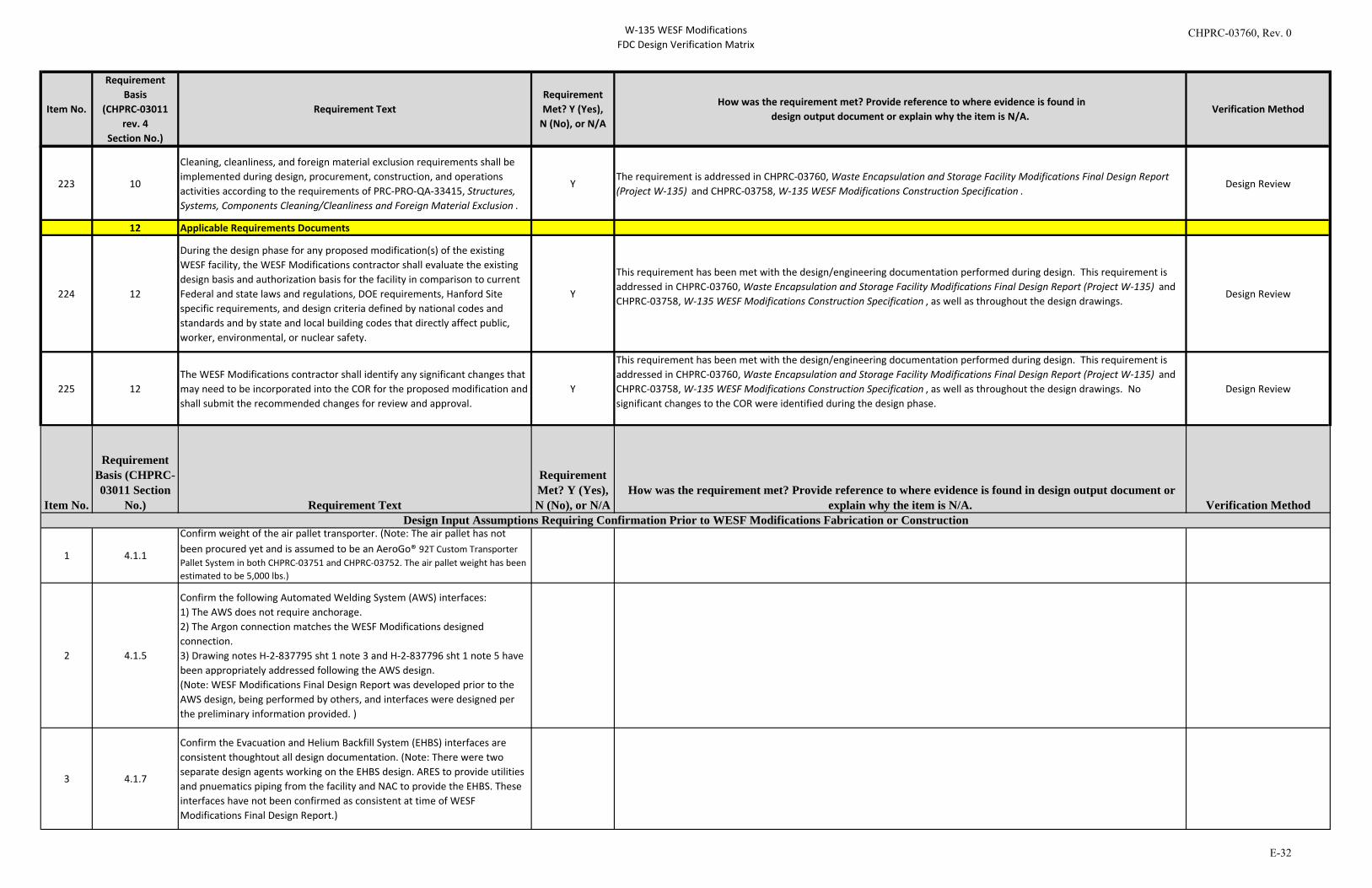
W-135 WESF ModificationsFDC Design Verification Matrix
Item No.
Requirement Basis
(CHPRC-03011 rev. 4
Section No.)
Requirement TextRequirement Met? Y (Yes),
N (No), or N/A
How was the requirement met? Provide reference to where evidence is found indesign output document or explain why the item is N/A.
Verification Method
223 10
Cleaning, cleanliness, and foreign material exclusion requirements shall be implemented during design, procurement, construction, and operations activities according to the requirements of PRC-PRO-QA-33415, Structures, Systems, Components Cleaning/Cleanliness and Foreign Material Exclusion .
YThe requirement is addressed in CHPRC-03760, Waste Encapsulation and Storage Facility Modifications Final Design Report (Project W-135) and CHPRC-03758, W-135 WESF Modifications Construction Specification .
Design Review
12 Applicable Requirements Documents
224 12
During the design phase for any proposed modification(s) of the existing WESF facility, the WESF Modifications contractor shall evaluate the existing design basis and authorization basis for the facility in comparison to current Federal and state laws and regulations, DOE requirements, Hanford Site specific requirements, and design criteria defined by national codes and standards and by state and local building codes that directly affect public, worker, environmental, or nuclear safety.
Y
This requirement has been met with the design/engineering documentation performed during design. This requirement is addressed in CHPRC-03760, Waste Encapsulation and Storage Facility Modifications Final Design Report (Project W-135) and CHPRC-03758, W-135 WESF Modifications Construction Specification , as well as throughout the design drawings.
Design Review
225 12The WESF Modifications contractor shall identify any significant changes that may need to be incorporated into the COR for the proposed modification and shall submit the recommended changes for review and approval.
Y
This requirement has been met with the design/engineering documentation performed during design. This requirement is addressed in CHPRC-03760, Waste Encapsulation and Storage Facility Modifications Final Design Report (Project W-135) and CHPRC-03758, W-135 WESF Modifications Construction Specification , as well as throughout the design drawings. No significant changes to the COR were identified during the design phase.
Design Review
1 4.1.1
Confirm weight of the air pallet transporter. (Note: The air pallet has not been procured yet and is assumed to be an AeroGo® 92T Custom Transporter Pallet System in both CHPRC-03751 and CHPRC-03752. The air pallet weight has been estimated to be 5,000 lbs.)
2 4.1.5
Confirm the following Automated Welding System (AWS) interfaces: 1) The AWS does not require anchorage.2) The Argon connection matches the WESF Modifications designedconnection.3) Drawing notes H-2-837795 sht 1 note 3 and H-2-837796 sht 1 note 5 havebeen appropriately addressed following the AWS design.(Note: WESF Modifications Final Design Report was developed prior to theAWS design, being performed by others, and interfaces were designed perthe preliminary information provided. )
3 4.1.7
Confirm the Evacuation and Helium Backfill System (EHBS) interfaces are consistent thoughtout all design documentation. (Note: There were two separate design agents working on the EHBS design. ARES to provide utilities and pnuematics piping from the facility and NAC to provide the EHBS. These interfaces have not been confirmed as consistent at time of WESF Modifications Final Design Report.)
Design Input Assumptions Requiring Confirmation Prior to WESF Modifications Fabrication or ConstructionItem No.
Requirement Basis (CHPRC-03011 Section
No.) Requirement Text
Requirement Met? Y (Yes),N (No), or N/A
How was the requirement met? Provide reference to where evidence is found in design output document or explain why the item is N/A. Verification Method
CHPRC-03760, Rev. 0
E-32

CHPRC-03760, Rev. 0
F-1
APPENDIX F
NAC GOVERNMENT-FURNISHED EQUIPMENT LIST
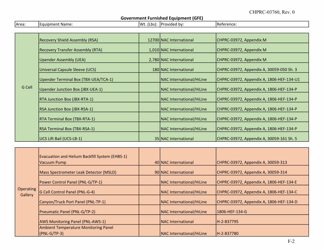
Area: Equipment Name: Wt. (Lbs): Provided by: Reference:
Recovery Shield Assembly (RSA) 12700 NAC International CHPRC‐03972, Appendix M
Recovery Transfer Assembly (RTA) 1,010 NAC International CHPRC‐03972, Appendix M
Upender Assembly (UEA) 2,780 NAC International CHPRC‐03972, Appendix M
Universal Capsule Sleeve (UCS) 180 NAC International CHPRC‐03972, Appendix A, 30059‐050 Sh. 3
Upender Terminal Box (TBX‐UEA/TCA‐1) NAC International/HiLine CHPRC‐03972, Appendix A, 1806‐HEF‐134‐U1
Upender Junction Box (JBX‐UEA‐1) NAC International/HiLine CHPRC‐03972, Appendix A, 1806‐HEF‐134‐P
RTA Junction Box (JBX‐RTA‐1) NAC International/HiLine CHPRC‐03972, Appendix A, 1806‐HEF‐134‐P
RSA Junction Box (JBX‐RSA‐1) NAC International/HiLine CHPRC‐03972, Appendix A, 1806‐HEF‐134‐P
RTA Terminal Box (TBX‐RTA‐1) NAC International/HiLine CHPRC‐03972, Appendix A, 1806‐HEF‐134‐P
RSA Terminal Box (TBX‐RSA‐1) NAC International/HiLine CHPRC‐03972, Appendix A, 1806‐HEF‐134‐P
UCS Lift Bail (UCS‐LB‐1) 35 NAC International CHPRC‐03972, Appendix A, 30059‐161 Sh. 5
Evacuation and Helium Backfill System (EHBS‐1)Vacuum Pump 40 NAC International CHPRC‐03972, Appendix A, 30059‐313
Mass Spectrometer Leak Detector (MSLD) 90 NAC International CHPRC‐03972, Appendix A, 30059‐314
Power Control Panel (PNL‐G/TP‐1) NAC International/HiLine CHPRC‐03972, Appendix A, 1806‐HEF‐134‐E
G Cell Control Panel (PNL‐G‐4) NAC International/HiLine CHPRC‐03972, Appendix A, 1806‐HEF‐134‐C
Canyon/Truck Port Panel (PNL‐TP‐1) NAC International/HiLine CHPRC‐03972, Appendix A, 1806‐HEF‐134‐D
Pneumatic Panel (PNL‐G/TP‐2) NAC International/HiLine 1806‐HEF‐134‐G
AWS Monitoring Panel (PNL‐AWS‐1) NAC International H‐2‐837795Ambient Temperature Monitoring Panel (PNL‐G/TP‐3) NAC International/HiLine H‐2‐837780
G Cell
Operating Gallery
Government Furnished Equipment (GFE)CHPRC-03760, Rev. 0
F-2
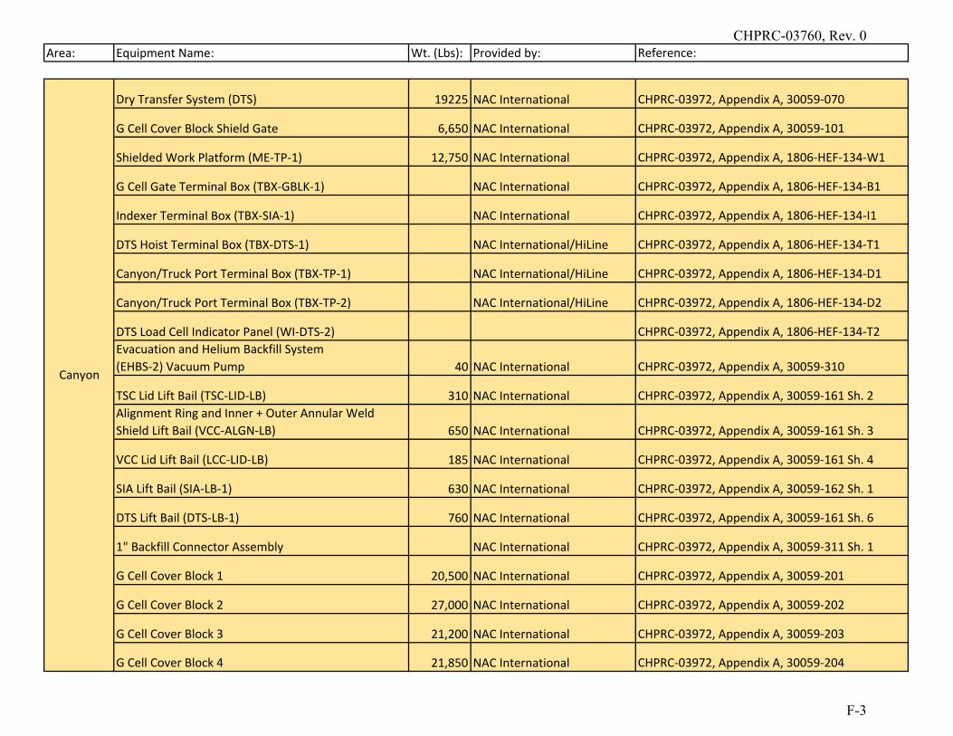
Area: Equipment Name: Wt. (Lbs): Provided by: Reference:
Dry Transfer System (DTS) 19225 NAC International CHPRC‐03972, Appendix A, 30059‐070
G Cell Cover Block Shield Gate 6,650 NAC International CHPRC‐03972, Appendix A, 30059‐101
Shielded Work Platform (ME‐TP‐1) 12,750 NAC International CHPRC‐03972, Appendix A, 1806‐HEF‐134‐W1
G Cell Gate Terminal Box (TBX‐GBLK‐1) NAC International CHPRC‐03972, Appendix A, 1806‐HEF‐134‐B1
Indexer Terminal Box (TBX‐SIA‐1) NAC International CHPRC‐03972, Appendix A, 1806‐HEF‐134‐I1
DTS Hoist Terminal Box (TBX‐DTS‐1) NAC International/HiLine CHPRC‐03972, Appendix A, 1806‐HEF‐134‐T1
Canyon/Truck Port Terminal Box (TBX‐TP‐1) NAC International/HiLine CHPRC‐03972, Appendix A, 1806‐HEF‐134‐D1
Canyon/Truck Port Terminal Box (TBX‐TP‐2) NAC International/HiLine CHPRC‐03972, Appendix A, 1806‐HEF‐134‐D2
DTS Load Cell Indicator Panel (WI‐DTS‐2) CHPRC‐03972, Appendix A, 1806‐HEF‐134‐T2Evacuation and Helium Backfill System (EHBS‐2) Vacuum Pump 40 NAC International CHPRC‐03972, Appendix A, 30059‐310
TSC Lid Lift Bail (TSC‐LID‐LB) 310 NAC International CHPRC‐03972, Appendix A, 30059‐161 Sh. 2Alignment Ring and Inner + Outer Annular Weld Shield Lift Bail (VCC‐ALGN‐LB) 650 NAC International CHPRC‐03972, Appendix A, 30059‐161 Sh. 3
VCC Lid Lift Bail (LCC‐LID‐LB) 185 NAC International CHPRC‐03972, Appendix A, 30059‐161 Sh. 4
SIA Lift Bail (SIA‐LB‐1) 630 NAC International CHPRC‐03972, Appendix A, 30059‐162 Sh. 1
DTS Lift Bail (DTS‐LB‐1) 760 NAC International CHPRC‐03972, Appendix A, 30059‐161 Sh. 6
1" Backfill Connector Assembly NAC International CHPRC‐03972, Appendix A, 30059‐311 Sh. 1
G Cell Cover Block 1 20,500 NAC International CHPRC‐03972, Appendix A, 30059‐201
G Cell Cover Block 2 27,000 NAC International CHPRC‐03972, Appendix A, 30059‐202
G Cell Cover Block 3 21,200 NAC International CHPRC‐03972, Appendix A, 30059‐203
G Cell Cover Block 4 21,850 NAC International CHPRC‐03972, Appendix A, 30059‐204
Canyon
CHPRC-03760, Rev. 0
F-3
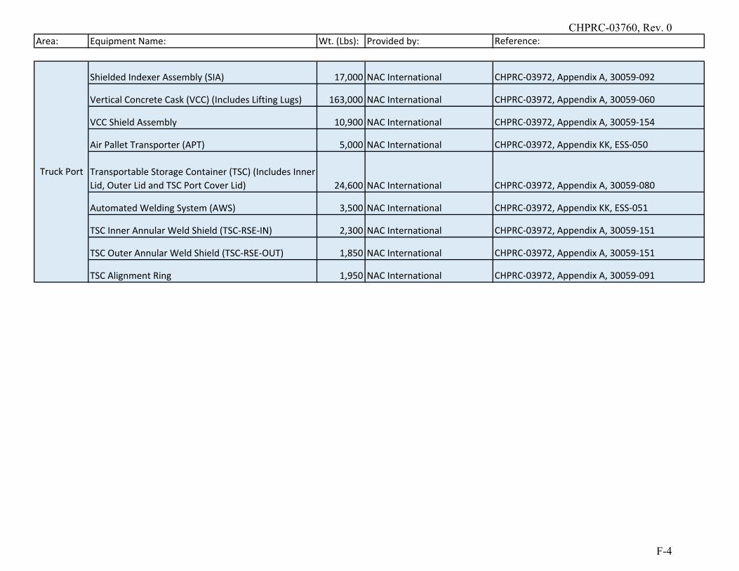
Area: Equipment Name: Wt. (Lbs): Provided by: Reference:
Shielded Indexer Assembly (SIA) 17,000 NAC International CHPRC‐03972, Appendix A, 30059‐092
Vertical Concrete Cask (VCC) (Includes Lifting Lugs) 163,000 NAC International CHPRC‐03972, Appendix A, 30059‐060
VCC Shield Assembly 10,900 NAC International CHPRC‐03972, Appendix A, 30059‐154
Air Pallet Transporter (APT) 5,000 NAC International CHPRC‐03972, Appendix KK, ESS‐050
Transportable Storage Container (TSC) (Includes Inner Lid, Outer Lid and TSC Port Cover Lid) 24,600 NAC International CHPRC‐03972, Appendix A, 30059‐080
Automated Welding System (AWS) 3,500 NAC International CHPRC‐03972, Appendix KK, ESS‐051
TSC Inner Annular Weld Shield (TSC‐RSE‐IN) 2,300 NAC International CHPRC‐03972, Appendix A, 30059‐151
TSC Outer Annular Weld Shield (TSC‐RSE‐OUT) 1,850 NAC International CHPRC‐03972, Appendix A, 30059‐151
TSC Alignment Ring 1,950 NAC International CHPRC‐03972, Appendix A, 30059‐091
Truck Port
CHPRC-03760, Rev. 0
F-4
Recommended