EE & CPE Senior Project
SPRING 2019
Weight Controlled Electric Skateboard
June 12th 2019
Carson Bertozzi
Vishnu Dodballapur
Zach Barram
Advisor: Paul Hummel

Contents
1 Acknowledgements 3
2 Abstract 3
3 Introduction 4
3.1 Stakeholders . . . . . . . . . . . . . . . . . . . . . . . . . . . . . . . . . . . . . . . . . . 4
3.2 Project Goals and Objectives . . . . . . . . . . . . . . . . . . . . . . . . . . . . . . . . 4
3.3 Project Outcomes and Deliverables . . . . . . . . . . . . . . . . . . . . . . . . . . . . . 4
4 Background 5
4.1 Last Mile Transportation . . . . . . . . . . . . . . . . . . . . . . . . . . . . . . . . . . 5
4.2 Current Industry . . . . . . . . . . . . . . . . . . . . . . . . . . . . . . . . . . . . . . . 5
5 Requirements and Technical Specifications 6
5.1 Requirements . . . . . . . . . . . . . . . . . . . . . . . . . . . . . . . . . . . . . . . . . 6
5.2 Technical Specifications . . . . . . . . . . . . . . . . . . . . . . . . . . . . . . . . . . . 6
6 Design 6
6.1 Design Review . . . . . . . . . . . . . . . . . . . . . . . . . . . . . . . . . . . . . . . . 6
6.1.1 Electric Skateboard . . . . . . . . . . . . . . . . . . . . . . . . . . . . . . . . . 7
6.1.2 Sensors . . . . . . . . . . . . . . . . . . . . . . . . . . . . . . . . . . . . . . . . 7
6.1.3 Digital Systems . . . . . . . . . . . . . . . . . . . . . . . . . . . . . . . . . . . . 8
7 Test Plans 9
7.1 Sensors . . . . . . . . . . . . . . . . . . . . . . . . . . . . . . . . . . . . . . . . . . . . 9
7.2 Stepping Onto the Board . . . . . . . . . . . . . . . . . . . . . . . . . . . . . . . . . . 10
7.3 Drive . . . . . . . . . . . . . . . . . . . . . . . . . . . . . . . . . . . . . . . . . . . . . . 10
7.4 Users of different weights . . . . . . . . . . . . . . . . . . . . . . . . . . . . . . . . . . 10
7.5 Different Terrain . . . . . . . . . . . . . . . . . . . . . . . . . . . . . . . . . . . . . . . 11
1

8 System Testing and Analysis 11
8.1 Sensors . . . . . . . . . . . . . . . . . . . . . . . . . . . . . . . . . . . . . . . . . . . . 11
8.2 Stepping Onto the Board . . . . . . . . . . . . . . . . . . . . . . . . . . . . . . . . . . 12
8.3 Drive . . . . . . . . . . . . . . . . . . . . . . . . . . . . . . . . . . . . . . . . . . . . . . 12
8.4 Users of different weights . . . . . . . . . . . . . . . . . . . . . . . . . . . . . . . . . . 13
8.5 Different Terrain . . . . . . . . . . . . . . . . . . . . . . . . . . . . . . . . . . . . . . . 13
9 Conclusion and Future Work 14
10 Teaming 15
11 Reflection 15
12 Bibliography 17
13 Appendices 17
13.1 code . . . . . . . . . . . . . . . . . . . . . . . . . . . . . . . . . . . . . . . . . . . . . . 17
List of Figures
1 Circuit Diagram of Sensor . . . . . . . . . . . . . . . . . . . . . . . . . . . . . . . . . . 8
2 Software Flowchart . . . . . . . . . . . . . . . . . . . . . . . . . . . . . . . . . . . . . . 9
2
1 Acknowledgements
We would like to offer our greatest of gratitude to everyone who had a hand in helping us along in
this project and some special thanks for:
James Poirier and Kyle Trambley for always being a willing beta testers for every iteration of the
skateboard (no matter how dangerous I made it seem).
Jordan Jones for always pushing us to have a project that was testable at all points in time and for
providing us with hardware to keep us moving along when shipping was just too slow.
We would also like to give very special gratitude to Paul Hummel. Dr. Hummel agreed to advise this
project out of the goodness of his heart as he was not obligated to advise projects as a lecturer at Cal
Poly. What he did not know he was agreeing to was being constantly being berated by Carson seeking
affirmation on every move that we were making. Dr. Hummel was instrumental in this project being
as successful as it is. He pushed us to keep moving forward and was always happy to help by providing
us hardware for testing or ideas on how to proceed forward.
2 Abstract
Technology and the way that humans interact is becoming more vital and omnipresent with every
passing day. However, human interface device designers suffer from the increasingly popular “designed
for me or people like me” syndrome. This design philosophy inherently limits accessibility and usability
of technology to those like the designer. This places severe limits of usability to those who are not
fully able as well as leaves non-traditional human interface devices unexplored. This project set out
to explore a previously uncharted human interface device, on an electric skateboard, and compare its
end user experience with industry leading human interface devices.
3
3 Introduction
The purpose of this project was to build an electric skateboard that changes its speed thresholds based
on the weight distribution of the rider between the front and back.
3.1 Stakeholders
Stakeholders would be people who don’t own a car looking to find a way to travel the last mile from
a public transit station to their actual destination, skateboard hobbyists, and high school and college
students. A successful product would give these people a convenient tool for transportation or a new
device to hack and play with.
3.2 Project Goals and Objectives
The goal of this project is to build a weight-controlled electric skateboard that match an already
assembled boosted boards functionality, affordability, and safety. The skateboard will be designed
to control the speed thresholds based on the natural body positions of the rider as they ride on the
board. For example, leaning forward will enable the board to go faster, leaning backward will engage
the brakes, and an even weight distribution across the board will coast. The skateboard will also
account for changes in terrain, and adjust its speed thresholds accordingly. For example, it will allow
for more speed going up a hill, and will cap the maximum speed going downhill in order to ensure the
rider’s safety.
3.3 Project Outcomes and Deliverables
A functional skateboard that meets the aforementioned requirements will be delivered, along with an
operator’s manual giving a brief overview on how the board works. A working product would help
to solve the last mile problem, give college and high school students a new way to easily get around
campus, and give skateboard hobbyists a new device to enjoy.
4
4 Background
4.1 Last Mile Transportation
The “Last Mile” has been a problem cities have been trying to solve for years. Getting around a city
is fairly straightforward, with subways and buses and other forms of public transportation, but rarely
do these methods bring a person to their exact desired location; rather, they just drop them off at a
station or something equivalent and leave it up to them to get home from there. As a result, people
have been devising safe, convenient, portable, and green methods to transport themselves over that
last mile to their destination. One of these solutions is an electric skateboard.
4.2 Current Industry
Initially starting out as a toy for the wealthy, electric skateboards have slowly been dipping in price,
making them an actually reasonable investment for someone like a college student who needs a conve-
nient method to get around without owning a car. Their cost comes in at anywhere between 200−1700,
depending on how high-end of a board the consumer is looking for.
Hobbyists often purchase parts (wheels, motors, deck, battery, etc.) and construct their own boards
themselves, although there are tradeoffs to be made when planning a design, and different users build
for their own specific needs. For example, a beginner would want a board that’s cheaper and less
powerful so that they can get comfortable with riding an electric skateboard, a user in a hilly neigh-
borhood would want a board with power, a user that uses their board for easy transportation would
want a board that’s lighter and portable.
One goal of this project was to build a board that would stack up with other boards already on the
market in terms of affordability and functionality, while adding its own features that set it apart.
5

5 Requirements and Technical Specifications
5.1 Requirements
As this project is focused on human interface devices, the needs of the end user were stringently
studied and followed. This data was compiled and is summarized below.
The board and its accompanying control system must:
• Match or exceed the speed of industry leading electric skateboards
• Match or exceed the acceleration of industry leading electric skateboards
• Match or exceed the battery range of industry leading electric skateboards
• Accept all weights and sizes of riders
• Be a viable last mile transportation vehicle
5.2 Technical Specifications
Below is a list of the technical specifications that satisfy the above requirements.
• Dual 190kv motors
• 3:1 gearing ratio
• 85mm wheels 77a hardness
• 42V 10s battery
6 Design
6.1 Design Review
This is a review of the primary subsystems of the project. These components are the Electric Skate-
board, Sensors, and the Digital Systems.
6
6.1.1 Electric Skateboard
The Electric Skateboard uses two 190kv motors each running with max 80 Amps of current on each
motor. The motors have a gear ratio of 3:1. These motors allow the skateboard to accelerate to a max
speed of 28 mph which is faster than most commercial electric skateboards. The motors are powered
from a 30Ah lithium ion battery. The charge time for the battery is approximately 4hr, giving the
board a range of approximately 10 miles, which is close to the average range of electric skateboards
on the market. This battery is connected to a programmable controller that regulates the amount
of current delivered to the batteries based on a PWM signal coming from the microcontroller. The
motors are mounted to the back of the board and are connected to 85mm wheels with a hardness of
77A. The battery and motor controller are shielded by an aluminum cover attached to the bottom.
The front wheels are attached to 63mm single bolt on mounted trucks. To bring it all together, the
deck of the board is a long-board covered in grip tape.
6.1.2 Sensors
The sensors are composed of a piece of Velostat sandwiched between two pieces of aluminum foil.
Velostat is a material that changes its resistance when it is folded or pressure is applied to it. There
are no official characteristics for this material, and the underlying cause for its properties are unknown,
but for the purpose of this project, the resistive range was found to be around 2kΩ with no pressure
applied to a flat 5 inch by 8 inch rectangle of the material, and around 30Ω with 200 pounds applied
to the same flat rectangle. The sensors were measured by creating a voltage divider with the sensor
connected to 3.3V and a 47Ω resistor connected to ground. The central node between these two
components was measured for its voltage.
7
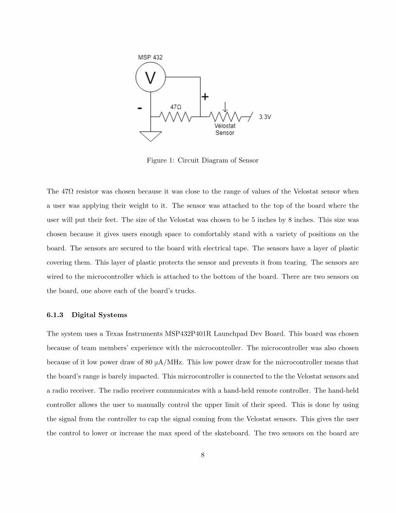
Figure 1: Circuit Diagram of Sensor
The 47Ω resistor was chosen because it was close to the range of values of the Velostat sensor when
a user was applying their weight to it. The sensor was attached to the top of the board where the
user will put their feet. The size of the Velostat was chosen to be 5 inches by 8 inches. This size was
chosen because it gives users enough space to comfortably stand with a variety of positions on the
board. The sensors are secured to the board with electrical tape. The sensors have a layer of plastic
covering them. This layer of plastic protects the sensor and prevents it from tearing. The sensors are
wired to the microcontroller which is attached to the bottom of the board. There are two sensors on
the board, one above each of the board’s trucks.
6.1.3 Digital Systems
The system uses a Texas Instruments MSP432P401R Launchpad Dev Board. This board was chosen
because of team members’ experience with the microcontroller. The microcontroller was also chosen
because of it low power draw of 80 μA/MHz. This low power draw for the microcontroller means that
the board’s range is barely impacted. This microcontroller is connected to the the Velostat sensors and
a radio receiver. The radio receiver communicates with a hand-held remote controller. The hand-held
controller allows the user to manually control the upper limit of their speed. This is done by using
the signal from the controller to cap the signal coming from the Velostat sensors. This gives the user
the control to lower or increase the max speed of the skateboard. The two sensors on the board are
8
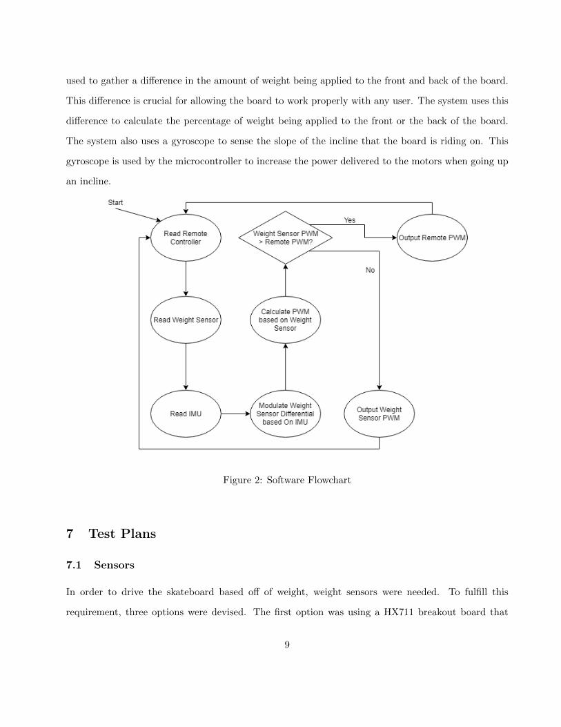
used to gather a difference in the amount of weight being applied to the front and back of the board.
This difference is crucial for allowing the board to work properly with any user. The system uses this
difference to calculate the percentage of weight being applied to the front or the back of the board.
The system also uses a gyroscope to sense the slope of the incline that the board is riding on. This
gyroscope is used by the microcontroller to increase the power delivered to the motors when going up
an incline.
Figure 2: Software Flowchart
7 Test Plans
7.1 Sensors
In order to drive the skateboard based off of weight, weight sensors were needed. To fulfill this
requirement, three options were devised. The first option was using a HX711 breakout board that
9
communicated via SPI that was hooked up to a load cell located underneath the trucks in the front
and back of the board. The second option was using a configuration of four load sensors underneath
the same trucks, hooked up to the same HX711 breakout board. The third option was to create a
voltage divider using a material that varied its resistance based off of pressure - called Velostat - and
read in the central node voltage using an ADC. To test how well each of these worked, the raw values
read from the breakout board in the first two cases and from the ADC in the third case were printed
out to the terminal via UART.
7.2 Stepping Onto the Board
Since the board uses a weight based system, a case would arise upon startup where the user would step
onto the board, setting a high weight differential and potentially causing the board to fly off in one
direction. The weight differential algorithm would then have to be modified to catch this condition.
To test this, the skateboard’s back wheels were elevated off of the ground by wooden blocks to ensure
the board did not drive anywhere, and the test user (Carson) would step onto the board to make sure
that the wheels did not start spinning.
7.3 Drive
It was imperative that actually riding the skateboard felt correct, and safe. Before actually riding,
the drive system was disengaged and the PWM signals generated by the microcontroller to feed into
the voltage controllers were read by an oscilloscope, and the waveforms were observed by the team to
determine if the skateboard’s behavior was the expected behavior. When driving, the microcontroller
was hooked up with a six foot cable to an external battery that was used as a kill switch in case
something went haywire and the board needed to be forced to power down.
7.4 Users of different weights
Initially, the board was tested with just one sensor on the front to ensure that the drive system worked.
However, as a result, a heavier user could put more weight on the sensor, and therefore drive faster
10
than a lighter user. In order to keep speeds consistent across differently weighted users, then, an
algorithm was developed to determine the speed window based off of the weight differential between
the front and back of the board. The algorithm was tested by disconnecting the drive system and
simply applying pressure on the front and back sensors and tracking the output of the algorithm,
which was printed out to the terminal via UART.
7.5 Different Terrain
The weight differential gives a window for the range of possible speed. However, this window teams
with gravity on a slope and makes for either a slow ascent when riding uphill or a rapid descent when
riding downhill. In order to adjust for this, it was necessary for an accelerometer to be integrated
into the system to shift the window given by the weight differential algorithm. To test this, the
accelerometer was held level on a table and moved back and forth, while reading the Euler angles and
printing the value onto the terminal via UART.
8 System Testing and Analysis
8.1 Sensors
Three sensors were tested to determine which would suit the system the best. First, load cells were
placed under the trucks and connected to the HX711 breakout board. The sensor’s readings were
output to a UART console. These readings were then analyzed to determine if they could detect the
full range of the user’s weight. These loads cells were maxed out at far too low of a value to be used
in this project. The second sensors that were tried were four scale weight sensors placed under the
board. These sensors had a variety of issues. The scale sensors could not fit in between the trucks
and the deck of the board. The sensor could be made to fit if a spacer piece was placed in between
the deck and the trucks. These sensors also were maxed out by a person’s full body weight. So these
sensors could not be used in the system. The final option was the use of a material called Velostat.
This is a material that changes its resistance based on the amount of pressure applied to it. Velostat
11
can be used to construct a weight sensor. This sensor was tested by measuring the resistance of the
material as more pressure was applied to it. The resistance of the sensor ranged from a value of 30kΩ
with no weight on it to 50Ω with around two hundred pounds of weight. It was determined that the
change in resistance was exponential.
8.2 Stepping Onto the Board
The initial startup of the board when the user first gets on was tested to make sure that the board
was safe. There was a bug in the system where the board would retain its previous settings after a
rider had dismounted the board. This meant that if a board were traveling quickly and then rapidly
dismounted, the next time a rider mounted the board it would use the acceleration value from before
the rapid dismount. This was solved by resetting the board’s speed value when the weight detected
by the sensors fell below a lower threshold. Early in development, the board would default to coasting
when the user stepped on the board. This feature was later changed so that the board allowed the
user to apply the brakes to the system while mounting the board. This led to a more user friendly
experience.
8.3 Drive
The PWM signal coming from the microcontroller was tested using an oscilloscope. This allowed
for verification of the signal before connecting the microcontroller to the speed controllers. During
development, the system used two different methods for determining the speed of the board. Initially,
the board used strictly the hand controller to determine the speed of the board. This is the standard
method of controlling electric skateboards. It allows for precise control of the board. This method
was tested with system test runs. By using the board on a variety of terrains it allowed for the
gathering of data and user feedback. While driving, the micro-controller’s battery was held by the
user. This allowed the user to pull the charging cable out of the battery. Pulling the charging cable
out of the battery causes the system to coast. Remote control operation was tested and worked
properly. The sensors were then added to the system, and this was tested separately. Testing with the
12

sensors revealed that many small changes needed to be made to the algorithm to make the system feel
comfortable to the user. The weight percentages were altered to make it so that the user did not have
to lean as much to get the change in acceleration that the user needed. A PID controller was added
to the algorithm to make changes in acceleration more gradual. The board’s top speed was tested
and it was found to be 28 mph, which is faster than most electric skateboards on the market. This
mean that we have met the speed requirement for this board. Acceleration exceeds other skateboard’s
accelerations on the market. The board’s traveling range is approximately 10 miles. As a last mile
transportation vehicle the board successfully fulfills the criteria of being convenient, portable, green,
and safe. The board is 15 pounds. This makes the boards comfortably portable for most users. This
portability and that the board charges in 4 hours makes the board a convenient option for short travel
distances. The board has two braking options which adds to the safety of a regular electric skateboard.
The board is an electric vehicle which makes it greener than gas powered alternatives.
8.4 Users of different weights
Several different users were tested on the board. This was to verify that the board would not need
any adjustment for users of different sizes. The algorithm used to determine the weight differential
does not use absolute weight values. Instead, the algorithm uses the difference in weight being applied
to the two sensors. This means that any user regardless of weight can operate the board. The users
tested varied in weight from one hundred fifteen pounds to two hundred pounds. All the users were
able to operate the board.
8.5 Different Terrain
The board was tested on a variety of inclinations. Inclinations caused the board to be too fast on
downward slopes and struggle to climb upward slopes. This bug was solved by using a gyroscope/ac-
celerometer that could determine the slope that the board was operating on. When the board goes
up a slope, it increases the amount of power being delivered to the motors, and on a downward slope,
it reduces the amount of power. This makes traversing a variety of terrains feasible.
13
9 Conclusion and Future Work
The project succeeded in some of its goals and failed in others. The goal of creating a viable last
mile transportation vehicle was realised. The skateboard on its own meets every requirement. It is
portable enough to be stored with a rider on a bus or train. It is safe to use as long as the rider has the
appropriate skill set. It is green due to it being entirely electrically powered. It is convenient because
its speed provides the rider with an effortless and fast way to commute. The project also succeeded
in the goal of exploring a previously unexplored human interface device, unfortunately that is where
the successes end.
The project failed in one key goal - creating a better human interface device on an electric skateboard
than the current industry available ones. One of the fundamental characteristics that make electric
skateboards both fun and safe to use as a commuting vehicle is their extremely high acceleration and
deceleration. The acceleration and deceleration allows the rider to get themselves out of a situation
where a car is coming up behind them or pulling in front of them without noticing that the rider is
there. The point of failure for the explored human interface device is that the weight based control
mechanism fundamentally can not safely function at the high levels of acceleration and deceleration
that is required for the board to be both safe and fun. As the levels of acceleration and deceleration
are increased the rider gets pushed back during acceleration and forward during deceleration to the
point that the control mechanism can not safely account for the change in rider position. This causes
the control mechanism to be unstable and ultimately not viable.
If there were to be future work done on this project or in this space there is an obvious point of entry.
That point is to use the newly added accelerometer to categorize the acceleration characteristics of
the system with a rider and use that to modulate the existing weight based control system. These
characteristics could be used to modify the control system which could enable the system to smoothly
and stably handle the acceleration and deceleration required to make a safe and fun electric skateboard.
This can be coupled with making the ending product more polished to the point that it can potentially
14
be a product that is ready for market.
10 Teaming
Below is a list of the contributing members on the team and their individual roles.
Carson Bertozzi - Project Lead
• Headed the project and made decisions about what direction the project went when difficulties
were encountered.
• Handled assigning tasks based on the strengths of each individual team member.
• Designed and coded the mains system architecture
• Designed and built the electric skateboard itself
Zach Barram
• Sensor testing and construction.
• Assisted in writing the program for the board.
• Wrote code for communication with and initialization of the BNO055 IC.
Vishnu Dodballapur
• Assisted in constructing the electric skateboard
• Assisted in writing the hardware abstraction code for the microcontroller
• Assisted in designing the algorithm to drive the skateboard based off of weight differential
11 Reflection
Carson Bertozzi:
In this project, I got the chance to spec, design, build, and test a system as a whole. This experience
was invaluable as it was one of the first times that I was able to set parameters as I saw fit which made
me feel like I was making decisions and putting my engineering degree to use. I also got the chance
15
to manage the project, which was a new experience. I had a small ”team” that I was responsible for
dividing tasks between to best utilize their strengths. This was an introduction to project manage-
ment for me and in particular an engineering project. In order to be an effective manager I had be
able to gain a working knowledge of any new topic that the team brought up. Through this project I
found that I very much exjoy being an engineer and that project management may be something that
I persue in the future.
Vishnu Dodballapur:
In this project, I got a chance to build and test a whole system from the ground up. I got experience
with a whole bunch of hardware I had never used before. I learned how important it is to write
readable, clean code, since we’re working on the same project over such a long period of time, and it’s
critical that we understand why we did what we did when we did it. I also learned some techniques
in safely testing potentially dangerous systems. Overall, I was able to take away a lot of knowledge
from this project.
Zachary Barram:
For this team project, I worked with sensors more than I ever had before. This project required
sensors that were accurate and precise. This required us to do a lot of testing that I had never done
before. We found that the sensors available for purchase were not precise enough for this project. We
developed our own sensors that worked better than the manufactured sensors. This whole project
ended up being a lesson in why it may not always be the best to just buy a product; sometimes, it is
better to build them yourself. In this project I had to use a lot of unfamiliar code. My teammates had
already developed some code, and I had to understand and add to it. This required communication
with my team and careful analysis of the code base.
16
12 Bibliography
“Are Electric Skateboards the Solution to the ’Last Mile’ Challenge?” CleanTechnica, 20 Mar. 2016,
cleantechnica.com/2016/03/20/electric-skateboards-solution-last-mile-challenge/.
13 Appendices
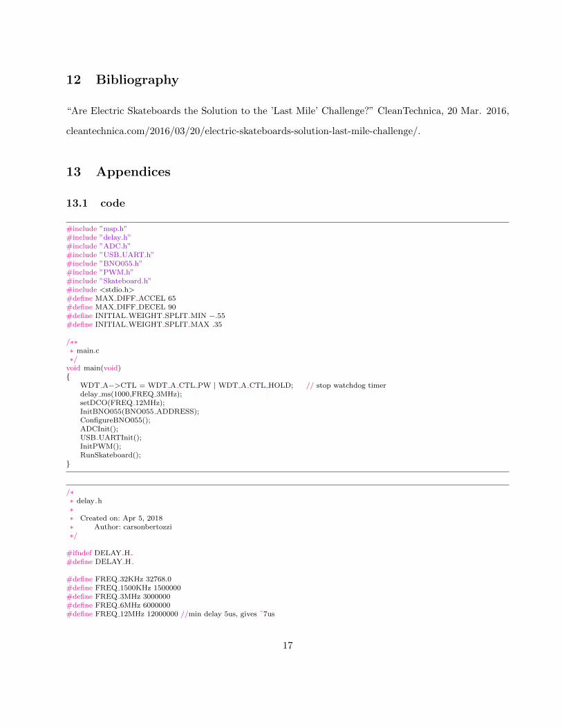
13.1 code
#include ”msp.h”#include ”delay.h”#include ”ADC.h”#include ”USB UART.h”#include ”BNO055.h”#include ”PWM.h”#include ”Skateboard.h”#include <stdio.h>#define MAX DIFF ACCEL 65#define MAX DIFF DECEL 90#define INITIAL WEIGHT SPLIT MIN −.55#define INITIAL WEIGHT SPLIT MAX .35
/∗∗∗ main.c∗/
void main(void){
WDT A−>CTL = WDT A CTL PW | WDT A CTL HOLD; // stop watchdog timerdelay ms(1000,FREQ 3MHz);setDCO(FREQ 12MHz);InitBNO055(BNO055 ADDRESS);ConfigureBNO055();ADCInit();USB UARTInit();InitPWM();RunSkateboard();
}
/∗∗ delay.h∗∗ Created on: Apr 5, 2018∗ Author: carsonbertozzi∗/
#ifndef DELAY H#define DELAY H
#define FREQ 32KHz 32768.0#define FREQ 1500KHz 1500000#define FREQ 3MHz 3000000#define FREQ 6MHz 6000000#define FREQ 12MHz 12000000 //min delay 5us, gives ˜7us
17
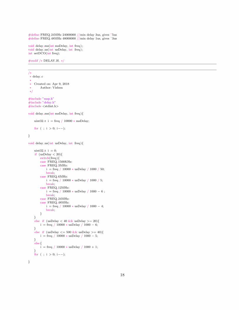
#define FREQ 24MHz 24000000 //min delay 3us, gives ˜5us#define FREQ 48MHz 48000000 //min delay 1us, gives ˜3us
void delay ms(int msDelay, int freq) ;void delay us(int usDelay, int freq) ;int setDCO(int freq);
#endif /∗ DELAY H ∗/
/∗∗ delay.c∗∗ Created on: Apr 9, 2018∗ Author: Vishnu∗/
#include ”msp.h”#include ”delay.h”#include <stdint.h>
void delay ms(int msDelay, int freq){
uint32 t i = freq / 10000 ∗ msDelay;
for ( ; i > 0; i−−);
}
void delay us(int usDelay, int freq){
uint32 t i = 0;if (usDelay < 20){
switch(freq){case FREQ 1500KHz:case FREQ 3MHz:
i = freq / 10000 ∗ usDelay / 1000 / 50;break;
case FREQ 6MHz:i = freq / 10000 ∗ usDelay / 1000 / 5;break;
case FREQ 12MHz:i = freq / 10000 ∗ usDelay / 1000 − 6 ;break;
case FREQ 24MHz:case FREQ 48MHz:
i = freq / 10000 ∗ usDelay / 1000 − 4;break;
}}else if (usDelay < 40 && usDelay >= 20){
i = freq / 10000 ∗ usDelay / 1000 − 6;}else if (usDelay <= 500 && usDelay >= 40){
i = freq / 10000 ∗ usDelay / 1000 − 5;}else{
i = freq / 10000 ∗ usDelay / 1000 + 1;}for ( ; i > 0; i−−);
}
18
int setDCO(int freq){uint32 t hold;CS−>KEY = CS KEY VAL; // unlock CS registershold = CS−>CTL0;CS−>CTL0 = 0; // clear register CTL0
switch(freq){
case FREQ 1500KHz:CS−>CTL0 |= CS CTL0 DCORSEL 0;break;
case FREQ 3MHz:CS−>CTL0 |= CS CTL0 DCORSEL 1;break;
case FREQ 6MHz:CS−>CTL0 |= CS CTL0 DCORSEL 2;break;
case FREQ 12MHz:CS−>CTL0 |= CS CTL0 DCORSEL 3;break;
case FREQ 24MHz:CS−>CTL0 |= CS CTL0 DCORSEL 4;break;
case FREQ 48MHz:/∗ Transition to VCORE Level 1: AM0 LDO −−> AM1 LDO ∗/while ((PCM−>CTL1 & PCM CTL1 PMR BUSY));
PCM−>CTL0 = PCM CTL0 KEY VAL | PCM CTL0 AMR 1;
while ((PCM−>CTL1 & PCM CTL1 PMR BUSY));
/∗ Configure Flash wait−state to 1 for both banks 0 & 1 ∗/FLCTL−>BANK0 RDCTL = (FLCTL−>BANK0 RDCTL &˜(FLCTL BANK0 RDCTL WAIT MASK)) | FLCTL BANK0 RDCTL WAIT 1;
FLCTL−>BANK1 RDCTL = (FLCTL−>BANK0 RDCTL &˜(FLCTL BANK1 RDCTL WAIT MASK)) | FLCTL BANK1 RDCTL WAIT 1;
CS−>CTL0 |= CS CTL0 DCORSEL 5;
break;default :
CS−>CTL0 = hold; //If value is not valid, put back original valueCS−>KEY = 0; //Lock the CS registerreturn −1;
}
CS−>CTL1 = CS CTL1 SELM DCOCLK | CS CTL1 SELS DCOCLK | CS CTL1 SELA REFOCLK; //Set the SMCLKsignal to the DCO clock
CS−>KEY = 0;
return 0;}
/∗∗ ADC.h∗∗ Created on: May 9, 2018∗ Author: Vishnu∗/
19
#ifndef ADC H#define ADC H
#include ”msp.h”
#define ADC V MAX 3.3#define RMS SAMPLE 36 36#define ADC RESOLUTION 16384#define ECCFF 495 //Extremely Carefully Calculated Fudge Factor
static uint8 t ADCFlag = 0;static uint16 t ADCSample = 0;static uint16 t ADCSample 1 = 0;
void ADCInit(void);void clearADCFlag(void);uint8 t getADCFlag(void);uint16 t getADCSample(void);uint16 t getADCSample 1(void);
#endif /∗ ADC H ∗/
/∗∗ ADC.c∗∗ Created on: May 9, 2018∗ Author: Vishnu∗/
#include ”ADC.h”
void ADCInit(void){P5−>SEL0 |= BIT4 | BIT5;P5−>SEL1 |= BIT4 | BIT5;
ADC14−>CTL0 &= ˜ADC14 CTL0 ENC;ADC14−>CTL0 = ADC14 CTL0 SHT0 16 | ADC14 CTL0 ON | ADC14 CTL0 SHP | ADC14 CTL0 CONSEQ 1;//sample for 16 clock cycles, turn on, sample manually, default clock, sequence of channels
ADC14−>CTL1 = ADC14 CTL1 RES 3; //set resolution to 14 bitsADC14−>MCTL[0] = ADC14 MCTLN INCH 1; //hook up A1, save in MEM0ADC14−>MCTL[1] = ADC14 MCTLN INCH 0 | ADC14 MCTLN EOS; //hook up A0, save in MEM1
ADC14−>IER0 |= ADC14 IER0 IE0 | ADC14 IER0 IE1; //enables interrupt for MEM[0] and MEM[1]ADC14−>CTL0 |= ADC14 CTL0 ENC;
enable irq () ;NVIC−>ISER[0] = (1 << ADC14 IRQn);
}
void clearADCFlag(void){ADCFlag = 0;
}
uint16 t getADCSample(void){return ADCSample;
}
uint16 t getADCSample 1(void){return ADCSample 1;
}
20
uint8 t getADCFlag(void){return ADCFlag;
}
void ADC14 IRQHandler(){if (ADC14−>IFGR0 & ADC14 IFGR0 IFG0){
ADCSample = ADC14−>MEM[0];ADCFlag = 1;
}else if (ADC14−>IFGR0 & ADC14 IFGR0 IFG1){
ADCSample 1 = ADC14−>MEM[1];ADCFlag = 1;
}}
void readFromBoard(uint16 t ∗ back input, uint16 t ∗ front input){ADC14−>CTL0 |= ADC14 CTL0 SC; //gets one front and back inputwhile ( !getADCFlag());clearADCFlag();∗back input = getADCSample();∗front input = getADCSample 1();
}
void calculateWeightDiff( float ∗ weight split , uint16 t back input, uint16 t front input){∗weight split = (float)(front input − back input) / (front input + back input);
if ((∗weight split ) > WEIGHT SPLIT MAX){∗weight split = WEIGHT SPLIT MAX;
}else if ((∗weight split ) < WEIGHT SPLIT MIN){∗weight split = WEIGHT SPLIT MIN;
}}
#ifndef PWM H#define PWM H
void PWMInit();
#endif
#include ”PWM.h”
void PWMInit(){/∗ Timer input capture pins∗ P2.6 is capture, P2.4 is PWM out for V−Controllers∗/
P2−>SEL0 |= (BIT6 | BIT4); //setting throttle and turning inputsP2−>SEL1 &= ˜(BIT6);P2−>DIR &= ˜(BIT6);P2−>DIR |= BIT4;
TIMER A0−>CTL |= TIMER A CTL SSEL SMCLK | TIMER A CTL MC CONTINUOUS| TIMER A CTL CLR;
TIMER A0−>CCTL[1] |= TIMER A CCTLN OUTMOD 7;
TIMER A0−>CCTL[3] |= TIMER A CCTLN CM BOTH | TIMER A CCTLN CCIS CCIA| TIMER A CCTLN CAP | TIMER A CCTLN CCIE
21
| TIMER A CCTLN SCS;
enable irq () ;NVIC−>ISER[0] = (1 << TA0 N IRQn);
}
void calculatePWM(unt16 t ∗ calc pwm output, uint16 t ∗ prev pwm output, float slope, float weight split){∗calc pwm output = (int)PWM MIN + slope ∗ (weight split − WEIGHT SPLIT MIN);if ((∗calc pwm output) > (∗prev pwm output) + MAX DIFF ACCEL){∗calc pwm output = ∗prev pwm output + MAX DIFF ACCEL;
}else if ((∗calc pwm output) < (∗prev pwm output) − MAX DIFF DECEL){∗calc pwm output = ∗prev pwm output − MAX DIFF DECEL;
}}void outputSignal(uint16 t front input, uint16 t back input,uint16 t ∗calc pwm output,uint16 t ∗throttle diff){
if ( front input + back input < 1000){ //sets a minimum weight thresholdTIMER A0−>CCR[1] = 18000;∗calc pwm output = 18000;
}
else if ( throttle diff > (∗calc pwm output)){TIMER A0−>CCR[1] = ∗calc pwm output;
}
else{TIMER A0−>CCR[1] = ∗throttle diff;
}}
#include ”msp.h”#include ”delay.h”#include ”ADC.h”#include ”USB UART.h”#include ”BNO055.h”#include ”PWM.h”#include ”Skateboard.h”/∗∗ Skateboard.c∗∗/
uint16 t throttle diff ;uint16 t sampled flag;void RunSkateboard(void){
int16 t signed int gyro value;uint16 t back input, front input, calc pwm output, prev pwm output = PWM MIN;
float weight split min;float weight split max;float weight split , acc weight shift ;float slope = 1.0 ∗ (PWM MAX − PWM MIN) / (INITIAL WEIGHT SPLIT MAX − INITIAL WEIGHT SPLIT MIN);
while(1){readFromBoard(&back input,&front input)
if (sampled flag){//the flags ensure that the data is only edited all in one go,//instead of potentially sporadically changing based whenevercalculateWeightDiff(&weight split, back input, front input);calculatePWM(&calc pwm output,&prev pwm output,slope,weight split);
22
outputSignal(front input, back input, &calc pwm output, &throttle diff)prev pwm output = calc pwm output;sampled flag = 0;
}}
}
void TA0 N IRQHandler(void){static uint16 t turnRising, turnFalling ;static uint16 t turnCaps = 0;
if (TIMER A0−>CCTL[3] & TIMER A CCTLN CCIFG){if (turnCaps == 0){
turnRising = TIMER A0−>CCR[3];turnCaps++;
}else if (turnCaps == 1){
turnFalling = TIMER A0−>CCR[3];throttle diff = turnFalling − turnRising;sampled flag = 1;turnCaps = 0;
}}TIMER A0−>CCTL[3] &= ˜TIMER A CCTLN CCIFG;
}
23
Recommended