WESTINGHOUSE NON-PROPRIETARY CLASS 3
Turkey Point Units 3 and 4
WOG Reactor Vessel 60-Year Evaluation Minigroup Heatup and Cooldown Limit Curves for Normal Operation
Westinghouse Electric Company LLC
WAP-1509
Rvsio

WESTINGHOUSE NON-PROPRIETARY CLASS 3
WCAP-15092, Revision 3
Turkey Point Units 3 and 4
WOG Reactor Vessel 60-Year Evaluation Minigroup
Heatup and Cooldown Limit Curves
For Normal Operation
T. J. Laubham J. H. Ledger
May, 2000
Prepared by the Westinghouse Electric Company
for the WOG Reactor Vessel 60-Year Evaluation Minigroup
Approved:_______ C. H . Boyd, Manager Equipment & Materials Technology
Approved:_______________________ D. M. Trombola, Manager
Mechanical Systems Integration
WESTINGHOUSE ELECTRIC COMPANY LLC
Nuclear Services Division
P.O. Box 355
Pittsburgh, Pennsylvania 15230-0355
© 2000 Westinghouse Electric Company LLC
All Rights Reserved

PREFACE
This report has been technically reviewed and verified by: C6Ol '/ 4ý
E. Terek
RECORD OF REVISION
Revision 1: "* Updated all pressure-temperature curves using the 1996 App. G to Section XI of the ASME Code,
KIc from Code Case N-640 and the removal of the flange requirement per WCAP-15315. All
calculations for adjusted reference temperature remain unchanged from Revision 0. "* Text has been updated to support the use of the '96 App. G, KIc and elimination of the flange notch.
Revision 2: * Revised fluence values for the lower shell forging have been provided by FP&L and incorporated
into this revision. All appropriate text and tables have been updated to reflect the newfluence values.
No changes were required to be made to the PT Curves in Figures 9-1 to 9-4 and data points in
Tables 9-1 to 9-4.
Revision 3:
* This revision was developed to include the Pressure-Temperature curves from Revision 0 and the
latest data which was in Revision 2 (Note: updated data from Revision 2 did not change the ART
values). Sections 1, 2, 3, 9, and 10 were taken, in total, from Revision 0, and Sections 4, 5, 6, 7, and
8 were taken, in total, from Revision 2.
Turkey Point Units 3 and 4 Heatup and Cooldown Limit Curves

LEGAL NOTICE
This report was prepared by Westinghouse as an account of work sponsored by the Westinghouse Owners
Group (WOG). Neither the WOG, any member of the WOG, Westinghouse, nor any person acting on
behalf of any of them:
(A) Makes any warranty or representation whatsoever, express or implied, (I) with respect to the use of
any information, apparatus, method, process, or similar item disclosed in this report, including
merchantability and fitness for a particular purpose, (II) that such use does not infringe on or
interfere with privately owned rights, including any party's intellectual property, or (III) that this
report is suitable to any particular user's circumstance; or
(B) Assumes responsibility for any damages or other liability whatsoever (including any consequential
damages, even if the WOG or any WOG representative has been advised of the possibility of such
damages) resulting from any selection or use of this report or any information, apparatus, method,
process, or similar item disclosed in this report.
Turkey Point Units 3 and 4 Heatup and Cooldown Limit Curves

iii
TABLE OF CONTENTS
LIST OF TABLES v
LIST OF FIGURES vii
1.0 INTRODUCTION 1-1
2.0 PURPOSE 2-1
3.0 CRITERIA FOR ALLOWABLE PRESSURE-TEMPERATURE RELATIONSHIPS 3-1
4.0 CHEMISTRY FACTOR DETERMINATION 4-1
4.1 Chemistry Factor Methodology 4-1
4.1.1 Application of the Ratio Procedure 4-1
4.1.2 Temperature Effects on Surveillance Data 4-2
4.2 Surveillance Program Credibility Evaluation 4-6
4.2.1 Application of the Credibility Criteria 4-12
4.2.2 qA and How it was Determined 4-12
5.0 UNIRRADIATED PROPERTIES 5-1
5.1 Initial RTNDT of Beltline Materials 5-1
5.2 Determination of aI 5-2
5.3 Bolt-up Temperature 5-2
6.0 REACTOR VESSEL GEOMETRIC & SYSTEM PARAMETERS 6-1
6.1 Reactor Vessel Physical Dimensions and Operating Conditions 6-1
7.0 FLUENCE FACTOR DETERMINATION 7-1
7.1 Peak Clad Base Metal Interface Fluence for each Beltline Material 7-1
7.2 1/4T & 3/4T Thickness Fluence for each Beltline Material 7-3
7.3 Fluence Factors 7-5
Turkey Point Units 3 and 4 Heatup and Cooldown Limit Curves

iv
TABLE OF CONTENTS - (Continued)
8.0 CALCULATION OF ADJUSTED REFERENCE TEMPERATURE 8-1
8.1 Methodology 8-1
8.2 Adjusted Reference Temperature (ART) Calculations 8-2
9.0 HEATUP AND COOLDOWN PRESSURE-TEMPERATURE LIMIT CURVES 9-1
9.1 Introduction and Methodology 9-1
10.0 ENABLE TEMPERATURE CALCULATIONS 10-1
10.1 ASME Code Case N-5 14 Methodology 10-1
10.2 32 EFPY Enable Temperature 10-1
10.3 48 EFPY Enable Temperature 10-2
11 REFERENCES 11-1
Turkey Point Units 3 and 4 Heatup and Cooldown Limit Curves
V
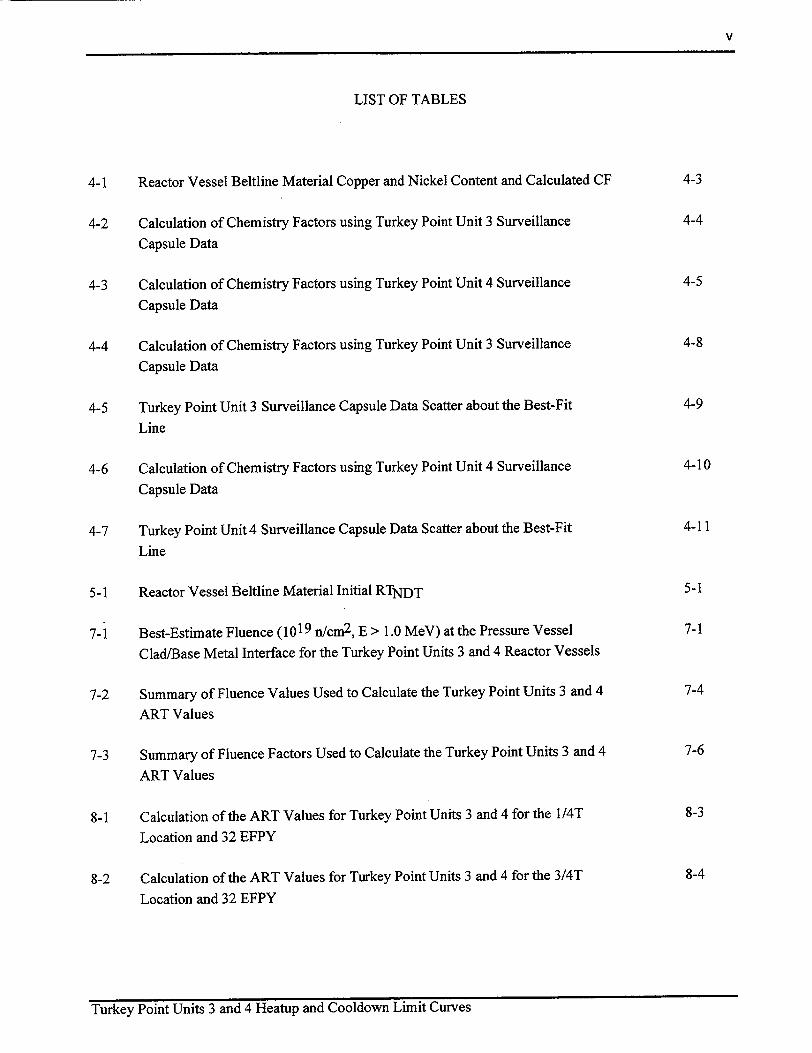
LIST OF TABLES
4-1 Reactor Vessel Beltline Material Copper and Nickel Content and Calculated CF 4-3
4-2 Calculation of Chemistry Factors using Turkey Point Unit 3 Surveillance 4-4
Capsule Data
4-3 Calculation of Chemistry Factors using Turkey Point Unit 4 Surveillance 4-5
Capsule Data
4-4 Calculation of Chemistry Factors using Turkey Point Unit 3 Surveillance 4-8
Capsule Data
4-5 Turkey Point Unit 3 Surveillance Capsule Data Scatter about the Best-Fit 4-9
Line
4-6 Calculation of Chemistry Factors using Turkey Point Unit 4 Surveillance 4-10
Capsule Data
4-7 Turkey Point Unit 4 Surveillance Capsule Data Scatter about the Best-Fit 4-11
Line
5-1 Reactor Vessel Beltline Material Initial RTNDT 5-1
7-1 Best-Estimate Fluence (1019 n/cm2 , E > 1.0 MeV) at the Pressure Vessel 7-1
Clad/Base Metal Interface for the Turkey Point Units 3 and 4 Reactor Vessels
7-2 Summary of Fluence Values Used to Calculate the Turkey Point Units 3 and 4 7-4
ART Values
7-3 Summary of Fluence Factors Used to Calculate the Turkey Point Units 3 and 4 7-6
ART Values
8-1 Calculation of the ART Values for Turkey Point Units 3 and 4 for the I/4T 8-3
Location and 32 EFPY
8-2 Calculation of the ART Values for Turkey Point Units 3 and 4 for the 3/4T 8-4
Location and 32 EFPY
Turkey Point Units 3 and 4 Heatup and Cooldown Limit Curves

vi
LIST OF TABLES - (Continued)
8-3 Calculation of the ART Values for Turkey Point Units 3 and 4 for the 1/4T 8-5
Location and 48 EFPY
8-4 Calculation of the ART Values for Turkey Point Units 3 and 4 for the 3/4T 8-6
Location and 48 EFPY
8-5 Summary of the Limiting Circumferential Weld Seam ART Values to be Used 8-7
in the Generation of the Turkey Point Reactor Vessel Heatup and Cooldown
Curves
8-6 Summary of the Limiting Forging ART Values to be Used in the Generation 8-7
of the Turkey Point Reactor Vessel Heatup and Cooldown Curves
9-1 Turkey Point Units 3 and 4 Reactor Vessel Heatup Curve Data Points for 9-7
32 EFPY Without Margins for Instrumentation Errors (Includes Vessel
Flange Requirements of 1640F and 621 psi per 1OCFR50)
9-2 Turkey Point Units 3 and 4 Reactor Vessel Cooldown Curve Data Points for 9-8
32 EFPY Without Margins for Instrumentation Errors (Includes Vessel Flange
Requirements of 164°F and 621 psi per 10CFR50)
9-3 Turkey Point Units 3 and 4 Reactor Vessel Heatup Curve Data Points for 48 9-9
EFPY Without Margins for Instrumentation Errors (Includes Vessel Flange
Requirements of 164°F and 621 psi per 10CFR50)
9-4 Turkey Point Units 3 and 4 Reactor Vessel Cooldown Curve Data Points for 9-10
48 EFPY Without Margins for Instrumentation Errors (Includes Vessel Flange
Requirements of 164'F and 621 psi per 1OCFR50)
Turkey Point Units 3 and 4 Heatup and Cooldown Limit Curves

vii
LIST OF FIGURES
9-1 Turkey Point Units 3 and 4 Reactor Coolant System Heatup Limitations (Heatup 9-3
Rates of 60 and 1 00°F/hr) Applicable for 32 EFPY (Without Margins for
Instrumentation Errors) (Includes Vessel Flange Requirements of 164'F
and 621 psi per 10CFR50)
9-2 Turkey Point Units 3 and 4 Reactor Coolant System Cooldown Limitations 9-4
(Cooldown Rates of 0, 20, 40, 60 and 100*F/hr) Applicable for 32 EFPY
(Without Margins for Instrumentation Errors) (Includes Vessel Flange
Requirements of 164°F and 621 psi per 1OCFR50)
9-3 Turkey Point Units 3 and 4 Reactor Coolant System Heatup Limitations (Heatup 9-5
Rate of 60 and 1 OO0 F/hr) Applicable for 48 EFPY (Without Margins for
Instrumentation Errors) (Includes Vessel Flange Requirements of 164°F
and 621 psi per I OCFR50)
9-4 Turkey Point Units 3 and 4 Reactor Coolant System Cooldown Limitations 9-6
(Cooldown Rates of 0, 20, 40, 60 and 100°F/hr) Applicable for 48 EFPY
(Without Margins for Instrumentation Errors) (Includes Vessel Flange
Requirements of 164 0F and 621 psi per 1OCFR50)
Turkey Point Units 3 and 4 Heatup and Cooldown Limit Curves

1-1
1.0 INTRODUCTION
Heatup and cooldown limit curves are calculated using the adjusted RTNDT (reference nil-ductility
temperature) corresponding to the limiting beitline region material of the reactor vessel. The adjusted
RTNDT of the limiting material in the core region of the reactor vessel is determined by using the
unirradiated reactor vessel material fracture toughness properties, estimating the radiationrinduced
ARTNDT, and adding a margin. The unirradiated RTNDT is designated as the higher of either the drop
weight nil-ductility transition temperature (NDTT) or the temperature at which the material exhibits at least
50 ft-lb of impact energy and 35-mil lateral expansion (normal to the major working direction) minus 60'F.
RTNDT increases as the material is exposed to fast-neutron radiation. Therefore, to find the most limiting
RTNDT at any time period in the reactor's life, ARTNDT due to the radiation exposure associated with that
time period must be added to the unirradiated RTNDT (IRTNDT). The extent of the shift in RTNDT is
enhanced by certain chemical elements (such as copper and nickel) present in reactor vessel steels. The
Nuclear Regulatory Commission (NRC) has published a method for predicting radiation embrittlement in
Regulatory Guide 1.99, Revision 2, "Radiation Embrittlement of Reactor Vessel Materials' 1 ]. Regulatory
Guide 1.99, Revision 2, is used for the calculation of Adjusted Reference Temperature (ART) values
(IRTNDT + ARTNDT + margins for uncertainties) at the 1/4T and 3/4T locations, where T is the thickness
of the vessel at the beltline region measured from the clad/base metal interface. The most limiting ART
values are used in the generation of heatup and cooldown pressure-temperature limit curves for normal
operation.
Turkey Point Units 3 and 4 Heatup and Cooldown Limit Curves

2-1
2.0 PURPOSE
Turkey Point Units 3 and 4, as members of the WOG Reactor Vessel 60-year Mini-group, have contracted
Westinghouse to generated new heatup and cooldown curves for the current end of license and life
extension. The Turkey Point Units 3 and 4 heatup and cooldown curves were generated without margins for
instrumentation errors. The curves include a hydrostatic leak test limit curve from 2485 to 2000 psig and
pressure-temperature limits for the vessel flange regions per the requirements of 10 CFR Part 50, Appendix
G[2].
The purpose of this report is to present the calculations and the development of Turkey Point Units 3 and 4
heatup and cooldown curves for the current end of license and license renewal. This report documents the
calculated adjusted reference temperature (ART) values following the methods of Regulatory Guide 1.99,
Revision 2[1], for all the beltline materials and the development of the heatup and cooldown pressure
temperature limit curves for normal operation.
Turkey Points Units 3 and 4 Heatup and Cooldown Limit Curves

3-1
3.0 CRITERIA FOR ALLOWABLE PRESSURE-TEMPERATURE RELATIONSHIPS
Appendix G to 10 CFR Part 50, "Fracture Toughness Requirements"12] specifies fracture toughness
requirements for ferritic materials of pressure-retaining components of the reactor coolant pressure boundary
of light water nuclear power reactors to provide adequate margins of safety during any condition of normal
operation, including anticipated operational occurrences and system hydrostatic tests, to which the pressure
boundary may be subjected over its service lifetime. The ASME Boiler and Pressure Vessel Code forms the
basis for these requirements. Section XI, Division 1, "Rules for Inservice Inspection of Nuclear Power Plant
Components", Appendix G[3], contains the conservative methods of analysis.
Appendix G was recently revised to incorporate the most recent elastic solutions for KI due to pressure and
radial thermal gradients. The new solutions are based on finite element analyses for inside surface flaws
performed at Oak Ridge National Laboratories and sponsored by the NRC, and work published for outside
surface flaws. These solutions provide results that are very similar to those obtained by using solutions
previously developed by Raju and Newman.
This revision, now provides consistent computational methods for pressure and thermal KI for thermal
gradients through the vessel wall at any time during the transient. Consistent with the original version of
Appendix G, no contribution for crack face pressure is included in the KI due to pressure, and cladding
effects are neglected.
Using these most recent elastic solutions in the low temperature region will provide some relief to
restrictions associated with reactor operation at relatively low temperatures. The pressure-temperature
curves for Turkey Point Units 3 and 4 will be developed using the current ASME Section XI, Appendix G
methodology and using the Code Case N-588 circumferential flaw methodology. The reason for using both
methodologies is that the limiting beltline material for both vessels is the circumferential weld seam and the
circumferential flaw methodology (Code Case N-588) provides enough relief at the lower end of the
pressure-temperature curves to cause the forging material to become limiting at lower temperatures.
Turkey Points Units 3 and 4 Heatup and Cooldown Limit Curves

3-2
The following revisions were made to ASME Section XI, Appendix G:
G-2214.1 Membrane Tension:
Km,, = M,,, x(pR / t)
where:
Mm for an inside axial surface flaw is given by:
Mm = 1.85 for1- 0 < 2,
Mm 0.926 f 0 for 2•7 < • 3.464,
Mm = 3.21 for t 0 > 3.464
Mm for an outside axial surface flaw is given by:
Mm = 1.77 for IT 0 < 2,
Mm = 0.893i-0 for 2•1,•t<3.464,
Mm 3.09 for it 0 > 3.464
and p = internal pressure, Ri = vessel inner radius, and t = vessel wall thickness.
Mm for an inside circumferential surface defect is given by:
Mm = 0.89 for It < 2
Mm = 0.443 ft17 for 2 < • < 3.464
Mm = 1.53 for 17 > 3.464
Mm for an outside circumferential surface defect is given by:
Mm = 0.89 for 1 <2
Mm = 0.443 17 for 2 17 •t -< 3.464
Mm = 1.53 for 17 > 3.464
and p = internal pressure, Ri = vessel inner radius, and t = vessel wall thickness.
Turkey Points Units 3 and 4 Heatup and Cooldown Limit Curves

3-3
G-2214.3 Radial Thermal Gradient:
The maximum KI produced by radial thermal gradient for the postulated inside surface defect of
G-2120 is Kit = 0.953x1o- 3 x CR x t2 -5, where CR is the cooldown rate in 'F/hr., or for a postulated outside
surface defect, KIt = 0.753x10- 3 x HU x t2 -5 , where HU is the heatup rate in 'F/hr.
The through-wall temperature difference associated with the maximum thermal Iq can be determined from
Fig. G-2214-1. The temperature at any radial distance from the vessel surface can be determined from Fig.
G-2214-2 for the maximum thermal KI.
(a) The maximum thermal KI relationship and the temperature relationship in Fig. G-2214-1 are
applicable only for the conditions given in G-2214.3(a)(1) and (2).
(b) Alternatively, the KI for radial thermal gradient can be calculated for any thermal stress
distribution and at any specified time during cooldown for a ¼-thickness inside surface defect using the
relationship:
KI, = (1.0359 Co + 0. 6322 C, + 0. 4 753 C2 + 0.3855 C3) *
or similarly, KIT during heatup for a ¼-thickness outside surface defect using the relationship:
K,, = (1.043 Co + 0. 630 C, + 0.481C 2 +0.401C3)*
where the coefficients C0 , C1, C2 and C3 are determined from the thermal stress distribution at any
specified time during the heatup or cooldown using the form:
o'(x) = Co + Cf(x / a)+ C 2(x / a ) 2 + C3(x / a)3
and x is a variable that represents the radial distance from the appropriate (i.e., inside or outside) surface to
any point on the crack front and a is the maximum crack depth.
Turkey Points Units 3 and 4 Heatup and Cooldown Limit Curves

3-4
Therefore, the governing equation for the heatup-cooldown analysis is defined in Appendix G of the ASME
Code as follows:
C * Kim + K11 < Ki0
where,
Kim = stress intensity factor caused by membrane (pressure) stress
KIt = stress intensity factor caused by the thermal gradients
KIa = function of temperature relative to the RTNDT of the material
C = 2.0 for Level A and Level B service limits
C = 1.5 for hydrostatic and leak test conditions during which the reactor core is not critical.
At any time during the heatup or cooldown transient, KIa is determined by the metal temperature at the tip
of a postulated flaw at the 1/4T and 3/4T location, the appropriate value for RTNDT, and the reference
fracture toughness curve. The thermal stresses resulting from the temperature gradients through the vessel
wall are calculated and then the corresponding (thermal) stress intensity factor, Kit, for the reference flaw
are computed. From Equation 2, the pressure stress intensity factors are obtained and, from these, the
allowable pressures are calculated.
For the calculation of the allowable pressure versus coolant temperature during cooldown, the reference flaw
of Appendix G to the ASME Code is assumed to exist at the inside of the vessel wall. Duringcooldown, the
controlling location of the flaw is always at the inside of the wall because the thermal gradients produce
tensile stresses at the inside, which increase with increasing cooldown rates. Allowable
pressure-temperature relations are generated for both steady-state and finite cooldown rate situations. From
these relations, composite limit curves are constructed for each cooldown rate of interest.
The use of the composite curve in the cooldown analysis is necessary because control of the cooldown
procedure is based on the measurement of reactor coolant temperature, whereas the limiting pressure is
actually dependent on the material temperature at the tip of the assumed flaw. During cooldown, the 1/4T
vessel location is at a higher temperature than the fluid adjacent to the vessel inner diameter. This condition,
of course, is not true for the steady-state situation. It follows that, at any given reactor coolant temperature,
the AT (temperature) developed during cooldown results in a higher value of KIa at the 1/4T location for
finite cooldown rates than for steady-state operation. Furthermore, if conditions exist so that the increase in
Turkey Points Units 3 and 4 Heatup and Cooldown Limit Curves

3-5
Kia exceeds Kit, the calculated allowable pressure during cooldown will be greater than the steady-state
value.
The above procedures are needed because there is no direct control on temperature at the 1/4T location and,
therefore, allowable pressures may unknowingly be violated if the rate of cooling is decreased at various
intervals along a cooldown ramp. The use of the composite curve eliminates this problem and ensures
conservative operation of the system for the entire cooldown period.
Three separate calculations are required to determine the limit curves for finiteheatup rates. As is done in
the cooldown analysis, allowable pressure-temperature relationships are developed for steady-state
conditions as well as finite heatup rate conditions assuming the presence of a 1/4T defect at the inside of the
wall. The heatup results in compressive stresses at the inside surface that alleviate the tensile stresses
produced by internal pressure. The metal temperature at the crack tip lags the coolant temperature;
therefore, the KIa for the 114T crack during heatup is lower than the KIa for the 1/4T crack during
steady-state conditions at the same coolant temperature. During heatup, especially at the end of the
transient, conditions may exist so that the effects of compressive thermal stresses and lowerKIa values do
not offset each other, and the pressure-temperature curve based on steady-state conditions no longer
represents a lower bound of all similar curves for finite heatup rates when the 1/4T flaw is considered.
Therefore, both cases have to be analyzed in order to ensure that at any coolant temperature the lower value
of the allowable pressure calculated for steady-state and finite heatup rates is obtained.
The second portion of the heatup analysis concerns the calculation of the pressure-temperature limitations
for the case in which a 1/4T flaw located at the 1/4T location from the outside surface is assumed. Unlike
the situation at the vessel inside surface, the thermal gradients established at the outside surface during
heatup produce stresses which are tensile in nature and therefore tend to reinforce any pressure stresses
present. These thermal stresses are dependent on both the rate of heatup and the time (or coolant
temperature) along the heatup ramp. Since the thermal stresses at the outside are tensile and increase with
increasing heatup rates, each heatup rate must be analyzed on an individual basis.
Following the generation of pressure-temperature curves for both the steady state and finite heatup rate
situations, the final limit curves are produced by constructing a composite curve based on a point-bypoint
comparison of the steady-state and finite heatup rate data. At any given temperature, the allowable pressure
is taken to be the lesser of the three values taken from the curves under consideration. The use of the
Turkey Points Units 3 and 4 Heatup and Cooldown Limit Curves

3-6
composite curve is necessary to set conservative heatup limitations because it is possible for conditions to
exist wherein, over the course of the heatup ramp, the controlling condition switches from the inside to the
outside, and the pressure limit must at all times be based on analysis of the most critical criterion.
10 CFR Part 50, Appendix G addresses the metal temperature of the closure head flange and vessel flange
regions. This rule states that the metal temperature of the closure flange regions must exceed the material
unirradiated RTNDT by at least 120'F for normal operation when the pressure exceeds 20 percent of the
preservice hydrostatic test pressure (3107 psig), which is 621 psig[4 ] for the Turkey Point Units 3 and 4
reactor vessels.
For the Turkey Point Unit 3 reactor vessel, the limitingunirradiated RTNDT is 440F[4 ] in the head flange
while the limiting unirradiated RTNDT for the Unit 4 reactor vessel is -l°F[4] in the vessel flange.
Therefore, the minimum allowable temperature for the two closure flange regions is 164°F at pressures
greater than 621 psig without uncertainties based upon the Unit 3 data. This limit is shown in Figures 9-1
through 9-4.
Turkey Points Units 3 and 4 Heatup and Cooldown Limit Curves

4-1
4.0 CHEMISTRY FACTOR DETERMINATION
4.1 Chemistry Factor Methodology:
The calculations of chemistry factor (CF) values for the Turkey Point Units 3 and 4 reactor vessel beltline
materials are performed in accordance with Regulatory Guide 1.99, Revision 2 as follows:
The CF is based on the Cu and Ni weight % of the material or it is based on the results of surveillance
capsule test data. When the weight percent of copper and nickel is used to determine the CF, the CF is
obtained from either Table 1 or Table 2 of Regulatory Guide 1.99, Revision 2.
When surveillance capsule data is used to determine the CF, the CF is determined as follows:
CF = i= I[A X ixfi12 8 o]j
j" [f Io.28.O.Jog) I
Where: n = The Number of Surveillance Data Points
Ai = The Measured Value of ARTNDT
fi = Fluence for each Surveillance Data Point
When the surveillance weld copper and nickel content differs from that of the vessel weld, the measured
values of ARTNDT are adjusted by multiplying them by the ratio of the chemistry factor for the vessel weld
to that for the surveillance weld based on the copper and nickel content of the materials. The Ratio
Procedure is documented in Regulatory Guide 1.99 Revision 2 Position 2.1, and shown below.
4.1.1 Application of the Ratio Procedure:
The Turkey Point Units 3 and 4 intermediate/lower shell circumferential weld seams, and the surveillance
program weld metal were all fabricated with weld wire Heat #71249 and Linde 80 flux. The surveillance
weld data is not credible. Note: The surveillance weld has a higher Cu than the bestestimate , therefore for
conservatism, the ratio procedure will not be applied to calculating the chemistry factor for the weld.
Turkey Points Units 3 and 4 Heatup and Cooldown Limit Curves

4-2
4.1.2 Temperature Effects on Surveillance Data:
Studies have shown that for temperatures near 550°F, a I 0F decrease in irradiation temperature will result in
approximately I1F increase in ARTNDT. Thus, for plants that use surveillance data from other reactor
vessels that operate at a different temperature or when the capsule is at a different temperature than the plant,
then this difference must be considered.
The temperature adjustment is as follows:
Temp. Adjusted ARTNDT = ARTNDT Measured + (Tcapsule - Tplant)
The Turkey Points Units 3 and 4 capsules are located in the reactor between the thermal shield and the
vessel wall and are positioned opposite the center of the core. The test capsules are in guide tubes attached
to the thermal shield. The location of the specimens with respect to the reactor vessel beitline provides
assurance that the reactor vessel wall and the specimens experience equivalent operating conditions and the
temperatures will not differ by more than 25°F. Since both plants are operated at the same temperature, no
temperature adjustment was made. However, one weld surveillance capsule data point is from the B&WOG
A-5 Capsule at Davis-Besse. The Tcold for Davis-Besse is 9°F higher than the Turkey Point (555°F vs.
546°F) and a 9°F correction was made. This is a conservative approach since the Davis Besse specimens
were irradiated at Turkey Point, tested and reconstituted, and re-irradiated at DavisBesse. Rather than do a
time weighted average, it was decided to assign all the time to the Davis Besse irradiation.
Turkey Points Units 3 and 4 Heatup and Cooldown Limit Curves

4-3
Following in Table 4-1 are best estimate chemistry values for all the beltline materials along with the
chemistry factors (CF) as determined per Regulatory Guide 1.99, Revision 2, Position 1 or 2
NOTES:
(a) These values were determined by FP&L and listed in Reference 4.
Turkey Points Units 3 and 4 Heatup and Cooldown Limit Curves
TABLE 4-1
Reactor Vessel Beltline Material Copper and Nickel Content and Calculated CF
Material Description wt. % Cu(a) wt. % Ni(a) CF
Turkey Point Unit 3
Intermediate Shell Forging 0.06 0.70 14.550 F
(Heat# 123P461VA1)
Int/Lower Shell Circ. Weld 0.23 0.59 167.55 0F (Heat # 71249)
Lower Shell Forging 0.08 0.67 42.70F
(Heat # 123S266VA1)
Turkey Point Unit 4
Intermediate Shell Forging 0.05 0.68 31OF
(Heat# 123P481VA1)
Int/Lower Shell Circ. Weld 0.23 0.59 167.55°F (Heat # 71249)
Lower Shell Forging 0.06 0.74 5.350 F
(Heat # 122S180VA1)

4-4
Tables 4-2 and 4-3 provide the calculation of the CF values for the surveillance materials per Regulatory
Guide 1.99, Revision 2, Position 2.1. The ratio procedure of Regulatory Guide 1.99, Revision 2,
Position 2.1 will not be applied to the weld metal (je. Ratio = 1.0) because the surveillance weld has
higher copper concentration than the best estimate chemistry.
(a) Fluence values are in units of n/cm2, E > 1.0 MeV.
(b) Data obtained from FP&L in Reference 4.
(c) The values shown are the rounded results from the FP&L spreadsheet calculations with up to eight
significant digits. The values may vary slightly from results calculated using the listings in the table.
Turkey Points Units 3 and 4 Heatup and Cooldown Limit Curves
TABLE 4-2
Calculation of Chemistry Factors using Turkey Point Unit 3 Surveillance Capsule Data
Material Capsule Fluence(-b) FF ART,,?)N FF * ART,,,() FF2
Inter. Shell S 1.72 x 10" 1.149 13'F 14.94 1.32
Forging T 0.74 x 10" 0.9155 180 F 16.48 0.838
123P461VA1 SUM: 31.42 2.158
Chemistry Factor = 14.55(l)
Lower Shell V 1.53 x 10" 1.1176 55'F 61.47 1.249
Forging S 1.72 x 10"9 1.149 42OF 48.27 1.32
123S266VA I SUM: 109.74 2.57
Chemistry Factor = 42.7(l)
Weld Metal Davis Besse 2.57 x 10"9 1.2530 225'F 281.93 1.570
SA11O0 and V3 1.539 x 10'9 1.1176 179°F 200.05 1.249
SA1094 T3 0.740 x 10"9 0.9155 166oF 151.97 0.8381
Heat #71249 T4 0.708 x 10'9 0.9031 211 F 190.55 0.8156
SUM: 824.52 4.473
Chemistry Factor = 184.3(c)

4-5
(a) Fluence values are in units of n/cm2 , E > 1.0 MeV.
(b) Data obtained from FP&L in Reference 4.
(c) Surveillance weldments SAl 101 (Unit 3) and SA1094 (Unit 4) were both fabricated using weld metal
Heat #71249 and Linde 80 flux (Lot #8445 for SAl 101 and Lot #8457 for SA1094).
(d) The values shown are the rounded results from the FP&L spreadsheet calculations with up to eight
significant digits. The values may vary slightly from results calculated using the listings in the table.
Turkey Points Units 3 and 4 Heatup and Cooldown Limit Curves
TABLE 4-3
Calculation of Chemistry Factors using Turkey Point Unit 4 Surveillance Capsule Data
Material J Capsule Fluenceý9O FF ARTJP) FF * ART,ýd) FF2
Inter. Shell S 1.43 x 10¹⁹ N/A 350F N/A N/A
123P481VAI SUM: N/A N/A
Chemistry Factor = N/A
Lower Shell S 1.43 x I0'" 1.099 00F 0 1.208
Forging T 0.708 x 10¹⁹ 0.903 12°F 10.84 0.815
122S180VA1 SUM: 10.84 2.023
Chemistry Factor = 5.35d)
Weld Metal Davis Besse 2.57 x 10⁹ 1.2530 225F 281.93 1.570
SAl 101 and T4 0.708 x 10¹⁹ 0.9031 1790F 200.05 0.8156
SA1094 V3 1.53 x 10¹⁹ 1.1176 166"F 151.97 1.249
Heat #71249(c) T3 0.74 x 10"9 0.9155 21 10F 190.55 0.8381
SUM: 824.52 4.473
Chemistry Factor = 184.3 (0d 1

4-6
4.2 Surveillance Program Credibility Evaluation:
Regulatory Guide 1.99, Revision 2, describes general procedures acceptable to the NRC staff for calculating
the effects of neutron radiation embrittlement of the low-alloy steels currently used for light-water-cooled
reactor vessels. Position C.2 of Regulatory Guide 1.99, Revision 2, describes the methodology for
calculating the adjusted reference temperature and Charpy upper-shelf energy of reactor vessel beltline
materials using surveillance capsule data. The methods of Position C.2 can only be applied when two or
more credible surveillance data sets become available from the reactor in question.
To date, there have been three surveillance capsules removed from the Turkey Point Unit 3 reactor vessel
and two from the Turkey Point Unit 4 reactor vessel. This capsule data must be shown to be credible. In
accordance with the discussion of Regulatory Guide 1.99, Revision 2, there are five requirements that must
be met for the surveillance data to be judged credible.
The purpose of this evaluation is to document the information provided by FP&L in regard to the Turkey
Point Units 3 and 4 reactor vessel surveillance data for each of the credibility requirements of Regulatory
Guide 1.99, Revision 2.
Criterion 1: Materials in the capsules should be those judged most likely to be controlling with regard
to radiation embrittlement
The beltline region of the reactor vessel is defined in Appendix G to 10 CFR Part 50, "Fracture Toughness
Requirements", December 19, 1995 to be:
"the reactor vessel (shell material including welds, heat affected zones, and plates orforgings) that directly
surrounds the effective height of the active core and adjacent regions of the reactor vessel that are predicted
to experience sufficient neutron radiation damage to be considered in the selection of the most limiting
material with regard to radiation damage."
The forging materials and weld metal contained in the capsules are representative of all of the materials in
the Turkey Point Units 3 and 4 reactor vessel beltline regions (Ref. 6 & 9). Therefore, the criteria is met.
Turkey Points Units 3 and 4 Heatup and Cooldown Limit Curves

4-7
Criterion 2: Scatter in the plots of Charpy energy versus temperature for the irradiated and
unirradiated conditions should be small enough to permit the determination of the 30ft
lb temperature and upper shelf energy, unambiguously.
The shift values used for this evaluation are the h-Tan shifts for surveillance data from the E-900
Database.[4] Therefore, this criteria is met.
Criterion 3: When there are two or more sets of surveillance data from one reactor, the scatter of
ARTNDT values about a best-fit line drawn as described in Regulatory Position 2.1
normally should be less than 280 Ffor welds and 170 Ffor base metal Even if the
fluence range is large (two or more orders of magnitude), the scatter should not exceed
twice those values. Even if the data fail this criterion for use in shift calculations, they
may be credible for determining decrease in upper shelf energy if the upper shelf can be
clearly determined, following the definition given in ASTM E185-82.
The least squares method, as described in Regulatory Position 2.1, will be utilized in determining a best-fit
line for this data to determine if this criteria is met.
Turkey Points Units 3 and 4 Heatup and Cooldown Limit Curves

4-8
(a) Fluence values are in units of n/cm2 , E > 1.0 MeV.
(b) Data obtained from FP&L in Reference 4.
(c) Surveillance program weldments SA1101 (Unit 3) and SA1094 (Unit 4) were both fabricated using
weld metal Heat #71249 and Linde 80 flux (Lot #8445 for SA1 101 and Lot #8457 for SA1094).
(d) The values shown are the rounded results from the FP&L spreadsheet calculations with up to eight
significant digits. The values may vary slightly from results calculated using the listings in the table.
Turkey Points Units 3 and 4 Heatup and Cooldown Limit Curves
TABLE 4-4
Calculation of Chemistry Factors using Turkey Point Unit 3 Surveillance Capsule Data
Material Capsule FluenceOab) FF ARTe) ] FF * ARTNrd) FF 2
Intermediate Shell S 1.72 x 10'9 1.149 13°F 14.94 1.32
Forging 123P461VA1 T 0.74 x 1 0 1' 0.9155 18OF 16.48 0.838
SUM: 31.42 2.158
Chemistry Factor = 14.55-d)
Lower Shell V 1.53 x 101 1.1176 55°F 61.47 1.249
Forging 123S266VA1 S 1.72 x 10¹⁹ 1.149 42°F 48.27 1.32
SUM: 109.74 2.57
Chemistry Factor= 42.7(_)
Surveillance Program Davis Besse 2.57 x 10¹⁹ 1.2530 225F 281.93 1.570
Weld Metal SA1101 V3 1.539 x 10's 1.1176 1790 F 200.05 1.249
and SA1094 T3 0.740 x 10 9 0.9155 166°F 151.97 0.8381
Heat #712490) T4 0.708 x 10's 0.9031 211*1F 190.55 0.8156
SUM: 824.52 4.473
Chemistry Factor = 184 .3(' -

4-9
TABLE 4-5
Turkey Point Unit 3 Surveillance Capsule Data Scatter about the Best-Fit Line
Material CF FF Measured Best Fit(a) Scatter <17 0F
(F) ART ARTNDT of
(_F)_(30 ft-Ib) (OF) ARTNT <28-F (OF) (OF)
Intermediate Shell 14.55 1.1492 13 16.73 -3.7 yes
Forging 123P461VA1 14.55 0.9155 18 13.3 4.7 yes
Lower Shell 42.7 1.1176 55 47.73 7.3 yes
Forging 123S266VA1 42.7 1.1492 42 49.07 -7.1 yes
Surveillance Program 184.3 1.2530 225 230.98 -5.98 yes
Weld Metal SA1101 184.3 1.1176 179 206.01 -27.01 yes
and SA1094 184.3 0.916 166 168.76 -2.76 yes
184.3 0.9031 211 166.46 44.54 no
(a) The values shown are the rounded results from the FP&L spreadsheet calculations with up to eight
significant digits. The values may vary slightly from results calculated using the listings in the table.
The scatter of ARTNDT values about a best-fit line drawn, as described in Regulatory Position 2.1, should
be less than 17'F for base metal. As shown above, the scatter of all data points is less than 17'F of the best
fit line. Therefore, the surveillance forging material data provided by FP&L is considered credible and was
used to determine the Adjusted Reference Temperatures (ARTs).
The scatter of ARTNDT values about a best-fit line drawn, as described in Regulatory Position 2.1, should
be less than 28°F for weld metal. As shown above, the scatter for one out of four points is greater than 280 F.
Therefore, the surveillance weld metal data provided by FP&L is not considered to be credible and was not
used to determine the Adjusted Reference Temperatures (ARTs). The ART for the weld metal was
determined using the table contained in Regulatory Guide 1.99, Revision 2.
Turkey Points Units 3 and 4 Heatup and Cooldown Limit Curves

4-10
TABLE 4-6
Calculation of Chemistry Factors using Turkey Point Unit 4 Surveillance Capsule Data
Material Capsule I Fluence(•b) FF ARTNOT@b) FF * ARTNT) [ FF2
Intermediate Shell S 1.43 x I0"9 N/A 35OF N/A N/A
Forging 123P481VA1 SUM: N/A N/A
Chemistry Factor = 31
Lower Shell S 1.43 x 10"9 1.099 O0F 0 1.208
Forging 122S180VA1 T 0.708 x 10¹⁹ 0.903 12°F 10.84 0.815
SUM: 10.84 2.0239
Chemistry Factor= 5 .3 5(d)
Surveillance Program Davis Besse 2.57 x 10"s 1.2530 225°F 281.93 1.570
Weld Metal SA1094 T4 0.708 x 10" 0.9031 179 0F 200.05 0.8156
and SA1101 V3 1.53 x 10' 1.1176 1667F 151.97 1.249
Heat #71249q) T3 0.74 x 10" 0.9155 21 IF 190.55 0.8381
SUM: 824.52 4.473
Chemistry Factor = 184.3(d
(a) Fluence values are in units of n/cm2 , E > 1.0 MeV.
(b) Data obtained from FP&L in Reference 4.
(c) Surveillance program weldments SAl101 (Unit 3) and SA1094 (Unit 4) were both fabricated using
weld metal Heat #71249 and Linde 80 flux (Lot #8445 for SA1101 and Lot #8457 for SA1094).
(d) The values shown are the rounded results from the FP&L spreadsheet calculations with up to eight
significant digits. The values may vary slightly from results calculated using the listings in the table.
Turkey Points Units 3 and 4 Heatup and Cooldown Limit Curves

4-11
____ ____ ___TABLE 4-7
Turkey Point Unit 4 Surveillance Capsule Data Scatter about the Best-Fit Line
Material CF FF Measured Best Fie) Scatter <17 0F
(OF) ARTmT ART,,T of (30 fi-lb) (OF) ARTNT <28-F
(OF) (OF)
Intermediate Shell N/A N/A 35 N/A N/A N/A Forging 123P481VAI
Lower Shell 5.35 1.099 10 5.89 4.11 yes
Forging 122S180VA1 5.35 0.9031 5 4.84 0.16 yes
Surveillance Program 184.3 1.2530 225 230.98 -5.98 yes
Weld Metal SA 1094 184.3 1.1176 179 206.01 -27.01 yes
and SA1101 184.3 0.916 166 168.76 -2.76 yes
184.3 0.9031 211 166.46 44.42 no
(a) The values shown are the rounded results from the FP&L spreadsheet calculations with up to eight
significant digits. The values may vary slightly from results calculated using the listings in the table.
The scatter of ARTNDT values about a best-fit line drawn, as described in Regulatory Position 2.1, should
be less than 17'F for base metal. As shown above, the scatter of all data points for the lower shell forging
122S 180VA I is less than 17'F of the best-fit line. Therefore, the surveillance forging material data for lower
shell forging 122S1 80VA1 provided by FP&L is considered credible and was used to determine the
Adjusted Reference Temperatures (ARTs). There is only one set of surveillance capsule data for
intermediate shell forging 123P481VA 1, and the requirement is at least two. Therefore, the tables of
Regulatory Guide 1.99, Revision 2, was used to determine the CF.
The scatter of ARTNDT values about a best-fit line drawn, as described in Regulatory Position 2.1, should
be less than 28°F for weld metal. As shown above, the scatter for one out of four points is greater than 28°F.
Therefore, the surveillance weld metal data provided by FP&L is not considered to be credible and was not
used to determine the Adjusted Reference Temperatures (ARTs). The ART for the weld metal was
determined using the table contained in Regulatory Guide 1.99, Revision 2.
Turkey Points Units 3 and 4 Heatup and Cooldown Limit Curves

4-12
Criterion 4: The irradiation temperature of the Charpy specimens in the capsule should match the
vessel wall temperature at the cladding/base metal interface within +/- 25 -F.
The temperature at the surveillance capsule locations is within 250F of the vessel wall temperature at the cladding/base metal interface during normal reactor operation. Therefore, this criteria is met.
Criterion 5: The surveillance data for the correlation monitor material in the capsule should fall within the scatter band of the data base for that material
There is no new correlation monitor material data.
4.2.1 Application of the Credibility Criteria:
According to information provided by FP&L in Reference 4:
The Turkey Point Unit 3 surveillance data for intermediate shell forging 123P461VA1 and lower shell forging 123S266VA1 is deemed credible in accordance with the credibility criteria of Regulatory Guide 1.99, Revision 2. The surveillance data for Turkey Point Unit 3 surveillance weld material SA1101 is
deemed not credible.
The Turkey Point Unit 4 surveillance data for lower shell forging 122S180VA1 is deemed credible in accordance with the credibility criteria of Regulatory Guide 1.99, Revision 2. The surveillance data for Turkey Point Unit 4 intermediate shell forging 123P481VA1 and surveillance weld material SA1094 are deemed not credible.
4.2.2 Gs and How it was Determined:
Per Regulatory Guide 1.99, Revision, 2 Position 1.1, the values of GA are referred to as "28°F for welds and
170F for base metal, except that GA need not exceed 0.50 times the mean value of ARTNDT." The "mean
value of ARTNDT" is defined in Regulatory Guide 1.99, Revision 2, by Equation 2. The chemistry factor in Regulatory Guide 1.99, Revision 2, Equation 2 is calculated from Tables 1 and 2 or Position 2.1 of
Regulatory Guide 1.99, Revision 2. When Position 2.1 is used, GA may be cut in half (i.e., 8.5°F and 14'F).
17'F and 28°F were used for forging 123P481VA1 and welds, respectively. Since the surveillance data is
credible for the forging materials, a CA of 8.5°F was used for all Turkey Point Units 3 and 4 forging
materials.
Turkey Points Units 3 and 4 Heatup and Cooldown Limit Curves

5-1
5.0 UNIRRADIATED. PROPERTIES
5.1 Initial RTNDT of Beltline Materials
Table 5-1 contains a description of the beltline materials and their initial RTNDTvalues.
NOTES:
(a) The Initial RTNT values were obtained from FP&L in Reference 4 and are measured values.
Turkey Point Unit 3 and 4 Heatup and Cooldown Limit Curves
TABLE 5-1
Reactor Vessel Material Initial RTNDT
Material Description Heat # Flux Type Flux Lot Initial RTNDT(a)
Turkey Point Unit 3
Closure Head Flange - - N/A N/A 440F
Vessel Flange - - N/A N/A -23 0F
Inter. Shell Forging 123P461VAI N/A N/A 40°F
Lower Shell Forging 123S266VA1 N/A N/A 30°F
Int/Lower Shell Circ. Weld 71249 Linde 80 8445 1 0°F
Turkey Point Unit 4
Closure Head Flange - - N/A N/A -40F
Vessel Flange - - N/A N/A -10F
Inter. Shell Forging 123P481VA1 N/A N/A 50°F
Lower Shell Forging 122S I80VA 1 N/A N/A 40°F
Int/Lower Shell Circ. Weld 71249 Linde 80 8445 100F

5-2
5.2 Determination of 9:
Since the initial RTNDT values are measured values, the Turkey Point Unit 3 and Turkey Point Unit 4 al
values are 0°F.
5.3 Bolt-up Temperature:
The minimum bolt-up temperature requirements for the Turkey Point Unit 3 and Unit 4 reactor pressure vessels are according to Paragraph G-2222 of the ASME Boiler and Pressure Vessel (B&PV) Code, Section XI, Appendix G, the reactor vessel may be bolted up and pressurized to 20 percent of the initial hydrostatic test pressure at the initial RTNDT of the material stressed by the bolt-up. Therefore, since the most limiting
initial RTNDT value is 44°F (Unit 3 closure head flange), the reactor vessel can be bolted up at 44°F. The
limiting initial RTNDT for the Unit 4 reactor vessel is only -IF. However, FP&L has specified minimum
bolt-up temperatures of 71 °F for Turkey Point Unit 3 and 70'F Turkey Point Unit 4 reactor vessels[4].
Turkey Point Unit 3 and 4 Heatup and Cooldown Limit Curves
7-1
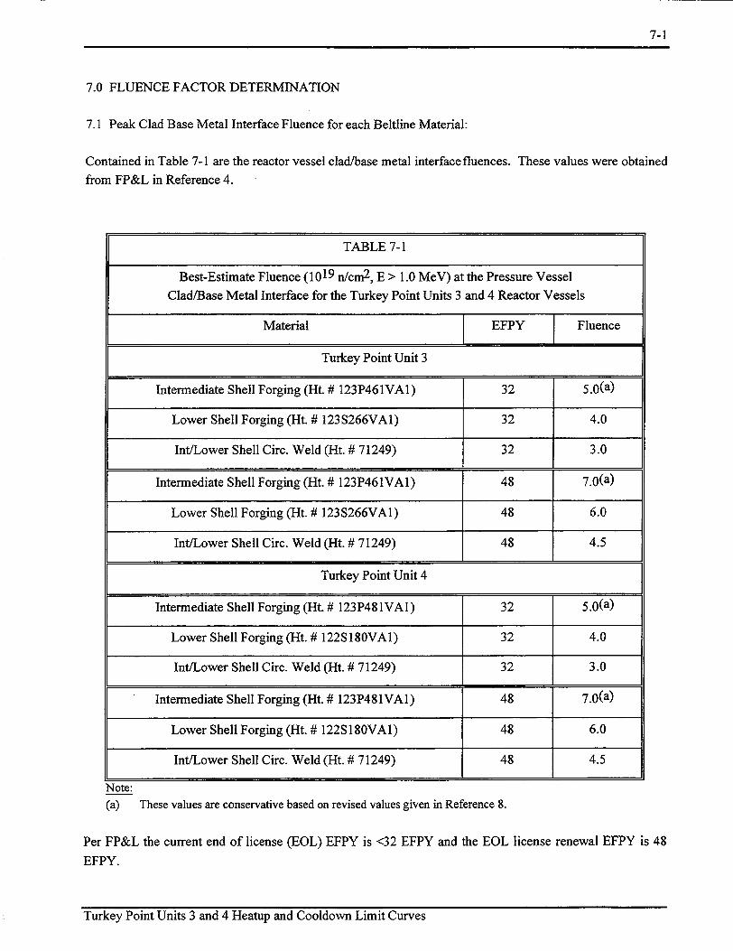
7.0 FLUENCE FACTOR DETERMINATION
7.1 Peak Clad Base Metal Interface Fluence for each Beltline Material:
Contained in Table 7-1 are the reactor vessel clad/base metal interface fluences. These values were obtained
from FP&L in Reference 4.
Note: (a) These values are conservative based on revised values given in Reference 8.
Per FP&L the current end of license (EOL) EFPY is <32 EFPY and the EOL license renewal EFPY is 48
EFPY.
Turkey Point Units 3 and 4 Heatup and Cooldown Limit Curves
TABLE 7-1
Best-Estimate Fluence (1019 n/cm2 , E > 1.0 MeV) at the Pressure Vessel Clad/Base Metal Interface for the Turkey Point Units 3 and 4 Reactor Vessels
Material EFPY Fluence
Turkey Point Unit 3
Intermediate Shell Forging (Ht. # 123P461VA1) 32 5.0(a)
Lower Shell Forging (Ht. # 123S266VA1) 32 4.0
Int/Lower Shell Circ. Weld (Ht. # 71249) 32 3.0
Intermediate Shell Forging (Ht. # 123P461VA1) 48 7.0(a)
Lower Shell Forging (Ht. # 123 S266VA1) 48 6.0
Int/Lower Shell Circ. Weld (Ht. # 71249) 48 4.5
Turkey Point Unit 4
Intermediate Shell Forging (Ht. # 123 P481VA 1) 32 5.0(a)
Lower Shell Forging (Ht. # 122S180VA1) 32 4.0
Int/Lower Shell Circ. Weld (Ht. # 71249) 32 3.0
Intermediate Shell Forging (Ht. # 123P481VAT) 48 7.0(a)
Lower Shell Forging (Ht. # 122S180VA1) 48 6.0
Int/Lower Shell Circ. Weld (Ht. # 71249) 48 4.5

7-2
Thus, the EFPY values used to generate pressure/temperature curves and the calculated fluence values are:
Current EOL = 32 EFPY
Renewal EOL = 48 EFPY
Turkey Point Units 3 and 4 each have only one beltline weld (i.e., the circumferential weld between the
intermediate and lower shell forgings). These beltline circumferential welds for Turkey Point Units 3 and 4
reactor vessels were fabricated with the same weld wire and flux. A portion of the circumferential welds will
receive the peak vessel fluence at the core centerline. Only this peak vessel fluence will be used for the ART
calculations for the welds. As for the intermediate and lower shell forgings, the applicable peak vessel
fluences will be used for the ART calculations.
Turkey Point Units 3 and 4 Heatup and Cooldown Limit Curves

6-1
6.0 REACTOR VESSEL GEOMETRIC & SYSTEM PARAMETERS
6.1 Reactor Vessel Physical Dimensions and Operating Conditions:
The following are the Turkey Point Units 3 and 4 reactor vessel physical dimensions and operating
conditions:
Reactor vessel inner diameter (to clad) = 155.5 inches
Clad thickness = 0.156 inches
Reactor Vessel Beltline Thickness = 7.75 inches
Pre-Service System Hydrostatic Pressure = 3107 psig
Capacity Factor (Future Cycles) = 90%
System and Component Operating Conditions/Dimensions:
Design Pressure = 2485 psig
Operating Pressure = 2235 psig
Turkey Point Units 3 and 4 Heatup and Cooldown Limit Curves

7-3
7.2 l/4T & 3/4T Thickness Fluence for each Beltline Material:
The neutron fluence at the 1/4T & 3/4T depth in the vessel wall was calculated per Regulatory Guide 1.99,
Revision 2, as follows:
f= fsurf* e{-0.2 4 (x)}, 1019 n/cm 2 (E > 1.0 MeV)
where: fsurf = Vessel inner wall surface fluence, 1019 n/cm2 (E > 1.0 MeV) (See Table 7-1)
x = is the depth into the vessel wall from the inner surface, inches
(0.25 * 7.75 inches or 0.75 * 7.75 inches)
Contained in Table 7-2 is a summary of the fluence values used to calculate the Turkey Point Units 3 and 4
ART values used to develop the pressure-temperature curves for normal operation.
Turkey Point Units 3 and 4 Heatup and Cooldown Limit Curves

7-4
TABLE 7-2
Summary of Fluence Values Used to Calculate the Turkey Point Units 3 and 4 ART Values
Material EFPY Peak Clad/Base 1/4T Fluence 3/4T Fluence
Metal Fluence (E > 1.0 MeV) (E > 1.0 MeV)
(E > 1.0 MeV)
Turkey Point Unit 3
Intermediate Shell Forging 32 5.0 x 10¹⁹ n/cm 2 3.11 x 10¹⁹ n/cm 2 1.20 x 10¹⁹ n/cm 2
(Ht. # 123P461VA1)
Lower Shell Forging 32 4.0 x 10¹⁹ n/cm2 2.49x 10¹⁹ n/cm 2 9.64x 10¹⁸ n/cm 2
(Ht. # 123S266VA1)
Int/Lower Shell Circ. Weld 32 3.0 x 10¹⁹ n/cm2 1.87 x 10¹⁹ n/cm 2 7.23 x 10¹⁸ n/cm 2
(Ht. # 71249)
Intermediate Shell Forging 48 7.0 x 10¹⁹ n/cm2 4.36 x 10¹⁹ n/cm 2 1.69 x 10¹⁹ n/cm 2
(Ht. # 123P461VA1)
Lower Shell Forging 48 6.0 x 10¹⁹ n/cm2 3.73 x 10¹⁹ n/cm 2 1.45 x 10¹⁹ n/cm 2
(Ht. # 123S266VA1)
Int/Lower Shell Circ. Weld 48 4.5 x 10¹⁹ n/cm2 2.80 x 10¹⁹ n/cm2 1.08 x 101 9 n/cm 2
(Ht. # 71249)
Turkey Point Unit 4
Intermediate Shell Forging 32 5.0 x 10¹⁹ n/cm2 3.11 x 10¹⁹ n/cm 2 1.20 x 10¹⁹ n/cm 2
(Ht. # 123P481VA1)
Lower Shell Forging 32 4.0 x 10¹⁹ n/cm 2 2.49 x 10¹⁹ n/cm 2 9.64 x 10¹⁸ n/cm 2
(Ht. # 122S180VA1)
Int/Lower Shell Circ. Weld 32 3.0 x 10¹⁹ n/cm 2 1.87 x i0 1 9 n/cm2 7.23 x 10¹⁸ n/cm2
(Ht. # 71249)
Intermediate Shell Forging 48 7.0 x 10¹⁹ n/cm2 4.36 x 10¹⁹ n/cm2 1.69 x 10¹⁹ n/cm 2
(Ht. # 123P481VA1)
Lower Shell Forging 48 6.0 x 10¹⁹ n/cm2 3.73 x 10¹⁹ n/cm2 1.45 x 10¹⁹ n/cm 2
(Ht. # 122S180VA1)
Int/Lower Shell Circ. Weld 48 4.5 x 10¹⁹ n/cm2 2.80 x 10¹⁹ n/cm 2 1.08 x 10¹⁹ n/cm 2
(Ht. # 71249)
Turkey Point Units 3 and 4 Heatup and Cooldown Limit Curves

7-5
7.3 Fluence Factors:
The fluence factors were calculated per Regulatory Guide 1.99, Revision 2, using the following equation.
FF = fluence factor = f(0.2 8 - 0.1 log (f))
where: f= Vessel inner wall surface fluence, 1/4 T fluence or 3/4T fluence,
[10 19 n/cm2 (E> 1.0 MeV) - 1019 n/cm2 (E> 1.0 MeV)]
Contained in Table 7-3 is a summary of the calculated fluence factors for 32 and 48 EFPY.
Turkey Point Units 3 and 4 Heatup and Cooldown Limit Curves

7-6
TABLE 7-3
Summary of Fluence Factors Used to Calculate the Turkey Point Units 3 and 4 ART Values
Material EFPY 1/4T Fluence Fluence 3/4T Fluence Fluence
(E > 1.0 MeV) Factor (E > 1.0 MeV) Factor
Turkey Point Unit 3
Inter. Shell Forging 32 3.11 x 10¹⁹ n/cm 2 1.30 1.20 x 10¹⁹ n/cm 2 1.05
(Ht. #123P461VA1)
Lower Shell Forging 32 2.49 x 10¹⁹ n/cm 2 1.25 9.64 x 10¹⁸ n/cm 2 0.99 (Ht. #123S266VA1)
Int/Lower Shell Circ. Weld 32 1.87 x 10¹⁹ n/cm 2 1.17 7.23 x 10¹⁸ n/cm2 0.91
Inter. Shell Forging 48 4.36 x 10¹⁹ n/cm2 1.37 1.69 x 10¹⁹ n/cm2 1.14
(Ht. #123P461VA1)
Lower Shell Forging 48 3.73 x 10¹⁹ n/cm2 1.34 1.45 x 10¹⁹ n/cm2 1.10
(Ht. #123S266VA1)
Int/Lower Shell Circ. Weld 48 2.80 x 10¹⁹ n/cm2 1.27 1.08 x 10¹⁹ n/cm2 1.02
Turkey Point Unit 4
Inter. Shell Forging 32 3.11 x 10¹⁹ n/cm2 1.30 1.20 x 10¹⁹ n/cm2 1.05
(Ht. #123P481VA1)
Lower Shell Forging 32 2.49 x 10¹⁹ n/cm2 1.25 9.64 x 10¹⁸ n/cm2 0.99
(Ht. #122S180VA1)
Int/Lower Shell Circ. Weld 32 1.87 x 10¹⁹ n/cm 2 1.17 7.23 x 10¹⁸ n/cm2 0.91
Inter. Shell Forging 48 4.36 x 10¹⁹ n/cm 2 1.37 1.69 x 10¹⁹ n/cm2 1.14
(Ht. #123P481VA1)
Lower Shell Forging 48 3.73 x 10¹⁹ n/cm 2 1.34 1.45 x 10¹⁹ n/cm 2 1.10
(Ht. # 122 S c 80VA 1)
Int/Lower Shell Circ. Weld 48 2.80 x 10 19 n/cm2 1.27 1.08 x 10¹⁹ n/cm2 1.02
Turkey Point Units 3 and 4 Heatup and Cooldown Limit Curves

8-1
8.0 CALCULATION OF ADJUSTED REFERENCE TEMPERATURE
8.1 Methodology:
From Regulatory Guide 1.99, Revision 2, the adjusted reference temperature (ART) for each material in the
beltline region is given by the following expression:
ART= Initial RTNDT +A RTNDT + Margin
Initial RTNDT is the reference temperature for the unirradiated material as defined in paragraph NB-2331 of
Section III of the ASME Boiler and Pressure Vessel Code[7]. If measured values of initial RTNDT for the
material in question are not available, generic mean values for that class of material may be used if there are
sufficient test results to establish a mean and standard deviation for the class.
ARTNDT is the mean value of the adjustment in reference temperature caused by irradiation and should be
calculated as follows:
A RTNDT = CF * f(o.28-o.lo0og9
To calculate ARTNDT at any depth (e.g., at 1/4T or 3/4T), the following formula must first be used to
attenuate the fluence at the specific depth. F = Fsurf (-.24x)
The resultant fluence is then placed in the equation above to calculate the ARTNDT at the specific depth.
The calculated CF and FF values are given in Tables 4-1 and 7-3 of this report.
When there are "two or more credible surveillance data sets'{1] available, Regulatory Guide 1.99 Revision
2, Position 2.1, states "To calculate the Margin in this case, use Equation 4; the values given there forcrA
may be cut in half'. Equation 4 from Regulatory Guide 1.99 Revision 2, is as follows:
M = 21j, +o
The values of (A are referred to as "28°F for welds and 17'F for base metals."
Standard Deviation for Initial RTNDT Margin Term, al: If the initial RTNDT values are measured values,
then 0I is taken to be 0°F, otherwise use 17'F.
Standard Deviation for ARTNDT Margin Term, (TA: Per Regulatory Guide 1.99 Revision 2, Position 1.1, the
values of 0 A are referred to as "28°F for welds and 17°F for base metal, except that GA need not exceed 0.50
times the mean value of ARTNDT." The "mean value of ARTNDT" is defined in Regulatory Guide 1.99
Revision 2, by Equation 2. The chemistry factor in Regulatory Guide 1.99, Revision 2, Equation 2 is
calculated from Tables 1 and 2 of Regulatory Guide 1.99 Revision 2.
Turkey Point Units 3 and 4 Heatup and Cooldown Limit Curves

8-2
Per Regulatory Guide 1.99, Revision 2, Position 2.1, when there is credible surveillance data, aA is taken to
be the lesser of ½/2ARTNDT or 14'F (28°F/2) for welds, or 8.5°F (17'F/2) for base metal. ARTNDT again
is defined herein by Equation 4, while utilizing a "Best-Fit Chemistry Factor" calculated in accordance with
Position 2.1 of Regulatory Guide 1.99, Revision 2.
Since aI is taken to be zero when a heat-specific measured value of initial RTNDT are available (as they are
in this case), the total margin term, based on Equation 4 of Regulatory Guide 1.99, Revision 2, is as follows:
Position 1.1: Lesser of ARTNDT or 56°F for Welds
Lesser of ARTNDT or 34°F for Base Metal
Position 2.1: Lesser of ARTNDT or 28°F for Welds
Lesser of ARTNDT or 17'F for Base Metal
8.2 Adjusted Reference Temperature (ART) Calculations:
The ART calculations along with the actual margin terms used for Turkey Point are listed in Tables 8-1
through 8-4.
Turkey Point Units 3 and 4 Heatup and Cooldown Limit Curves

8-3
(a) The values shown are the rounded results from the FP&L spreadsheet calculations with up to eight
significant digits. The values may vary slightly from results calculated using the listings in the table.
Turkey Point Units 3 and 4 Heatup and Cooldown Limit Curves

8-4
(a) The values shown are the rounded results from the FP&L spreadsheet calculations with up to eight
significant digits. The values may vary slightly from results calculated using the listings in the table.
Turkey Point Units 3 and 4 Heatup and Cooldown Limit Curves
TABLE 8-2
Calculation of the ART Values for Turkey Point Units 3 and 4 for the 3/4T Location and 32 EFPY
Material RG 1.99 CF FF ARTNDT Margin IRTNDT ART
R2 Method (a)
Turkey Point Unit 3
Intermediate Shell Forging Position 2.1 14.55°F 1.05 15.3 0F 170F 40°F 72.30F
(Ht. # 123P461VA1)
Lower Shell Forging Position 2.1 42.70F 0.99 42.30F 170F 30°F 89.30F
(Ht. # 123S266VA1)
IntlLower Shell Circ. Weld Position 1.1 167.55°F 0.91 152.3°F 560F 10°F 218.3oF
(Ht. # 71249)
Turkey Point Unit 4
Intermediate Shell Forging Position 2.1 31OF 1.05 32.55°F 340F 50°F 116.6 0F
(Ht. # 123P481VA1)
Lower Shell Forging Position 2.1 5.35°F 0.99 5.30F 170F 40°F 64.30F
(Ht. # 122S180VA1)
Int/Lower Shell Circ. Weld Position 1.1 167.55°F 0.91 152.30F 560F 10°F 218.3oF
(Ht. # 71249)

8-5
(a) The values shown are the rounded results from the FP&L spreadsheet calculations with up to eight
significant digits. The values may vary slightly from results calculated using the listings in the table.
Turkey Point Units 3 and 4 Heatup and Cooldown Limit Curves

8-6
(a) The values shown are the rounded results from the FP&L spreadsheet calculations with up to eight
significant digits. The values may vary slightly from results calculated using the listings in the table.
Turkey Point Units 3 and 4 Heatup and Cooldown Limit Curves

8-7
Contained in Tables 8-5 and 8-6 is a summary of the limiting ART values used in the generation of the
Turkey Point Units 3 and 4 reactor vessel heatup and cooldown curves.
EFPY 1/4 T Limiting ART 3/4 Limiting ART
32 2620F 218OF
48 280OF 237 0F
TABLE 8-6
Summary of the Limiting Forging ART Values to be Used in the
Generation of the Turkey Point Reactor Vessel
Heatup and Cooldown Curves
EFPY 1/4 T Limiting ART 3/4 Limiting ART
32 124 0F 117 0F
48 127 0F 119 0F
Turkey Point Units 3 and 4 Heatup and Cooldown Limit Curves
TABLE 8-5
Summary of the Limiting Circumferential Weld Seam ART Values to
be Used in the Generation of the Turkey Point Reactor Vessel
Heatup and Cooldown Curves

9-1
9.0 HEATUP AND COOLDOWN PRESSURE-TEMPERATURE LIMIT CURVES
9.1 Introduction and Methodology:
Pressure-temperature limit curves for normal heatup and cooldown of the primary reactor coolant system
have been calculated for the pressure and temperature in the reactor vessel beltline region using the methods
discussed in Sections 3 and 8 of this report.
Figure 9-1 presents the heatup curves without margins for possible instrumentation errors forheatup rates of
60 and 100°F/hr. This curve is applicable to 32 EFPY (current end of license). Figure 9-2 presents the
cooldown curves without margins for possible instrumentation errors for cooldown rates of 0, 20, 40, 60,
and 1 00°F/hr. These curves are also applicable to 32 EFPY (current end of license). Figure 9-3 presents the
heatup curves without margins for possible instrumentation errors for heatup rates of 60 and 100°F/hr.
These curves are applicable to 48 EFPY (end of license renewal). Figure 9-4 presents the cooldown curves
without margins for possible instrumentation errors for cooldown rates of 0, 20, 40, 60, and 100°F/hr. These
curves are also applicable to 48 EFPY (end of license renewal). Allowable combinations of temperature and
pressure for specific temperature change rates are below and to the right of the limit lines shown in Figures
9-1 through 9-4. This is in addition to other criteria which must be met before the reactor is made critical, as
discussed in the following paragraphs.
The reactor must not be made critical until pressure-temperature combinations are to the right of the
criticality limit line shown in Figures 9-1 and 9-3. The straight-line portion of the criticality limit is at the
minimum permissible temperature for the 2485 psig inservice hydrostatic test as required by Appendix G to
10 CFR Part 50. The governing equation for the hydrostatic test is defined in Appendix G to Section XI of
the ASME Code[ 3] as follows:
1.5 Kim < Kia
where,
Kim is the stress intensity factor covered by membrane (pressure) stress,
Kia= 26.78 + 1.233 exp [0.0145 (T - RTNDT + 160)],
T is the minimum permissible metal temperature, and
RTNDT is the metal reference nil-ductility temperature
Turkey Point Units 3 and 4 Heatup and Cooldown Limit Curves

9-2
The criticality limit curve specifies pressure-temperature limits for core operation to provide additional margin during actual power production as specified in Reference 2. The pressure-temperature limits for core operation (except for low power physics tests) are that the reactor vessel must be at a temperature equal to or
higher than the minimum temperature required for the inservice hydrostatic test, and at least 40'F higher than the minimum permissible temperature in the corresponding pressure-temperature curve for heatup and cooldown calculated as described in Section 3 of this report. The vertical line drawn from these points on
the pressure-temperature curve, intersecting a curve 40'F higher than the pressure-temperature limit curve, constitutes the limit for core operation for the reactor vessel.
Figures 9-1 through 9-4 define all of the above limits for ensuring prevention of nonductile failure for the Turkey Point Units 3 and 4 reactor vessels. The data points for the heatup and cooldown pressure-temperature limit curves shown in Figures 9-1 through 9-4 are presented in Tables 9-1 through
9-4.
Turkey Point Units 3 and 4 Heatup and Cooldown Limit Curves

9-3
MATERIAL PROPERTY BASIS
LIMITING MATERIAL: Intermediate/Lower Shell Circumferential Weld Seams (Ht. # 71249)
LIMITING ART VALUES AT 32 EFPY: 1/4T, 2620F
3/4T, 218°F
FPL 32 EFPY HEATUP CURVES
2500
2250
i
I/
I1 I I I
SI / I
1750
a 1500.
e 1250
0. u) S1000
UFmaoep i I-
Healp Pages I Up to6 Deg. FAT Upto 100 Deg. F/ff
60 Deg. F/r 10D Deg. Fftr
El
i i T I i f iI I I I crticality ULit Based on Inservice hydroc Test
Teperatrfe (293 Deg. F) forthe
Service Period Up to 32 EFPY
I I I I I I I I I I
I
50 100 150 200 250 300 350 400 450
RCS Twena~eti (Deg- F)
FIGURE 9-1 Turkey Point Units 3 and 4 Reactor Coolant System Heatup Limitations (Heatup Rate of
60 and 1 00°F/hr) Applicable for 32 EFPY (Without Margins for Instrumentation Errors)
(Includes Vessel Flange Requirements of 164 0F and 621 psi per 1OCFR50)
Turkey Point Units 3 and 4 Heatup and Cooldown Limit Curves
I x
tuu
o40
I I I
500 550
Boft-up emperature
I IilI
H
RCS~~
~~
1etr
(D.j FL

9-4
MATERIAL PROPERTY BASIS
LIMITING MATERIAL: Intermediate/Lower Shell Circumferential Weld Seams (Ht. # 71249)
LIMITING ART VALUES AT 32 EFPY: 1/4T, 262°F
3/4T, 218°F
FPL 32 EFr. COOincOiw CURVES
oori'
B 1500
S1250
o1000o
4,
750
500
250
0
0
I i I -! I I i i
I I I.L
"+ t
Boft-~,p Ten~rahze
t+
J /Y F/
Rates 100 Deg. F/h 60 Deg. F/r
2) Deg. Fhr 0 Deg. Ffhr
50 100 150 200 250 300 350 4450
RCS Tenpde (De% F)
FIGURE 9-2 Turkey Point Units 3 and 4 Reactor Coolant System Cooldown Limitations (Cooldown
Rates of 0, 20, 40, 60 and 100°F/hr) Applicable for 32 EFPY (Without Margins for Instrumentation Errors)
(Includes Vessel Flange Requirements of 1640F and 621 psi per 1OCFR50)
Turkey Point Units 3 and 4 Heatup and Cooldown Limit Curves
500
I
T, I
I ! J I -J:Z-i T
Z- -T T: L LI i I
Q=Acoeptable

9-5
MATERIAL PROPERTY BASIS
LIMITING MATERIAL: Intermediate/Lower Shell Circumferential Weld Seams (Ht. # 71249)
LIMITING ART VALUES AT 48 EFPY: 1/4T, 280-F
3/4T, 237 0F
m.488WHP3Q%
3
0 1
0 5 10 15 200 2D 300 3 4oD 450 M5
KSTffrj3&Me F)
FIGURE 9-3 Turkey Point Units 3 and 4 Reactor Coolant System Heatup Limitations (Heatup Rate of
60 and 100°F/hr) Applicable for 48 EFPY (Without Margins for Instrumentation Errors)
(Includes Vessel Flange Requirements of 164"F and 621 psi per 1OCFR50)
Turkey Point Units 3 and 4 Heatup and Cooldown Limit Curves

9-6
MATERIAL PROPERTY BASIS
LIMITING MATERIAL: Intermediate/Lower Shell Circumferential Weld Seams (Ht. # 71249)
LIMITING ART VALUES AT 48 EFPY: 1/4T, 280°F
3/4T, 237°F
H'L48EFW000DDMCUVW~
AMU
2O000
175D
B 150D
S125o
0,
S1000
0
-I I
,lI�
lEE 111111]I I I I
HHHHHHHHHHFIEIKEKKELEWE
, I -1 ^N I \Rtms
0eg FAY 40 De FAr 20J •S F/hr 0Deg. FAT
Pa�1�1e
50 100 15D 2Co 25o 30D 350 400 4,5
FRSTe1rpramP4 F)
FIGURE 9-4 Turkey Point Units 3 and 4 Reactor Coolant System Cooldown Limitations (Cooldown
Rates of 0, 20, 40, 60 and 100 0F/hr) Applicable for 48 EFPY (Without Margins for
Instrumentation Errors) (Includes Vessel Flange Requirements of 164°F and 621 psi per IOCFR50)
Turkey Point Units 3 and 4 Heatup and Cooldown Limit Curves
I I I Boft-tp T,.t.
I I ,
i i I illi ]I [II
UmowpWe Cpe4cn
0
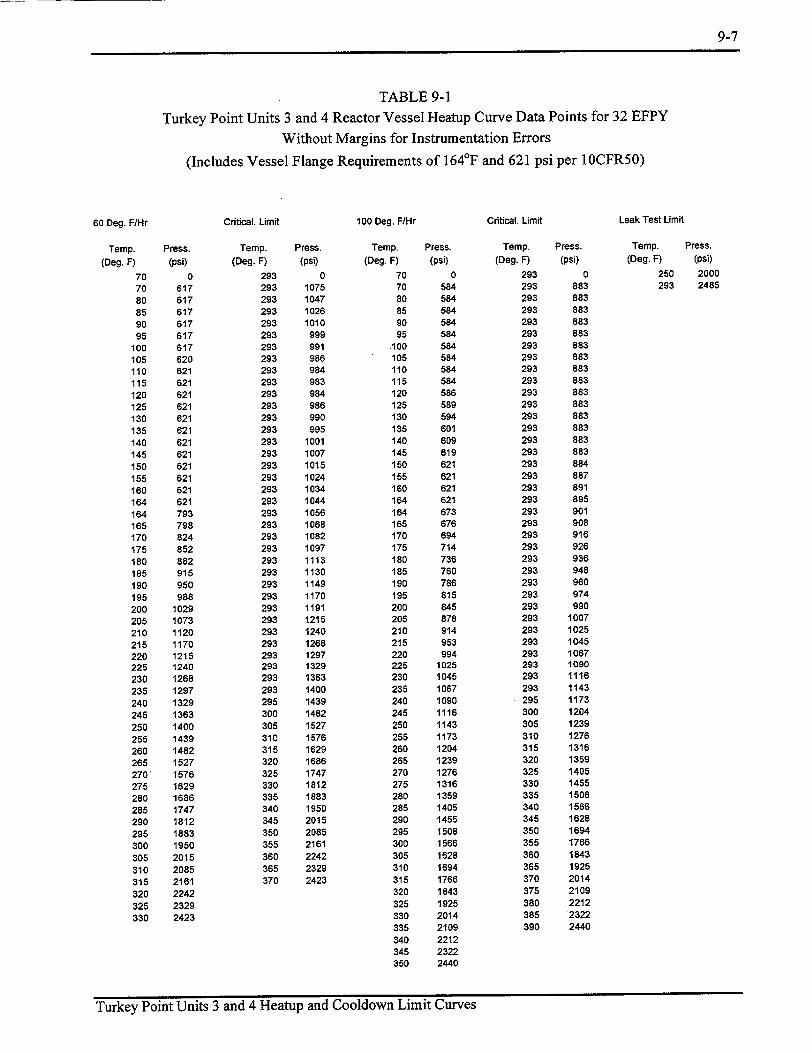
9-7
TABLE 9-1
Turkey Point Units 3 and 4 Reactor Vessel Heatup Curve Data Points for 32 EFPY
Without Margins for Instrumentation Errors
(Includes Vessel Flange Requirements of 164 0F and 621 psi per 1OCFR50)
Critical. Limit 100 Deg. F/Hr Critical. Limit Leak Test Limit
Temp. Press.
(Deg. F) (psi)
70 0 70 617 80 617 85 617 90 617 95 617
100 617 105 620 110 621 115 621 120 621 125 621 130 621 135 621 140 621 145 621 150 621 155 621 160 621 164 621 164 793 165 798 170 824 175 852 180 882 185 915 190 950 195 988
200 1029 205 1073 210 1120 215 1170 220 1215 225 1240 230 1268 235 1297 240 1329 245 1363 250 1400 255 1439 260 1482 265 1527 270' 1576 275 1629 280 1686 285 1747 290 1812 295 1883 300 1950 305 2015 310 2085 315 2161 320 2242 325 2329 330 2423
Temp. Press. (Deg. F) (psi)
293 0 293 1075 293 1047 293 1026 293 1010 293 999 293 991 293 986 293 984 293 983 293 984 293 986 293 990 293 995 293 1001 293 1007 293 1015 293 1024 293 1034 293 1044 293 1056 293 1068 293 1082 293 1097 293 1113 293 1130 293 1149 293 1170 293 1191 293 1215 293 1240 293 1268 293 1297 293 1329 293 1363 293 1400 295 1439 300 1482 305 1527 310 1576 315 1629 320 1686 325 1747 330 1812 335 1883 340 1950 345 2015 350 2085 355 2161
360 2242 365 2329 370 2423
Temp. Press.
(Deg. F) (psi)
70 0 70 584 80 584 85 584 90 584 95 584
100 584 105 584 110 584 115 584 120 586 125 589 130 594 135 601 140 609 145 619 150 621 155 621 160 621 164 621 164 673 165 676 170 694 175 714 180 736 185 760 190 786 195 815 200 845 205 878 210 914 215 953 220 994 225 1025 230 1045 235 1067 240 1090 245 1116 250 1143 255 1173 260 1204 265 1239 270 1276 275 1316 280 1359 285 1405 290 1455 295 1508 300 1566 305 1628 310 1694 315 1766 320 1843 325 1925 330 2014 335 2109
340 2212 345 2322 350 2440
Temp. Press. (Deg. F) (psi)
293 0 293 883 293 883 293 883 293 883 293 883 293 883 293 883 293 883 293 883 293 883 293 883 293 883 293 883 293 883 293 883 293 884 293 887 293 891 293 895 293 901 293 908 293 916 293 926 293 936 293 948 293 960 293 974 293 990 293 1007 293 1025 293 1045 293 1067 293 1090 293 1116 293 1143 295 1173 300 1204 305 1239 310 1276 315 1316 320 1359 325 1405 330 1455 335 1508 340 1566 345 1628 350 1694 355 1766 360 1843 365 1925 370 2014 375 2109
380 2212 385 2322 390 2440
Temp. Press. (Deg. F) (psi)
250 2000 293 2485
Turkey Point Units 3 and 4 Heatup and Cooldown Limit Curves
60 Deg. F/Hr

9-8
TABLE 9-2 Turkey Point Units 3 and 4 Reactor Vessel Cooldown Curve Data Points for 32 EFPY
Without Margins for Instrumentation Errors (Includes Vessel Flange Requirements of 164°F and 621 psi per 1OCFR50)
Steady State
Temp. Press. (Deg. F) (psi)
70 0 70 621 75 621 80 621 85 621 90 621 95 621
100 621 105 621 110 621 115 621 120 621 125 621 130 621 135 621 140 621 145 621 150 621 155 621 160 621 164 621 164 958 165 964 170 998 175 1034 180 1073 185 1114 190 1159 195 1208 200 1259 205 1299 210 1316 215 1334 220 1353 225 1373 230 1395 235 1419 240 1444 245 1472 250 1501 255 1533 260 1567 265 1604 270 1643 275 1685 280 1731 285 1780 290 1832 295 1889 300 1950 305 2015 310 2085 315 2161 320 2242 325 2329 330 2423
20 Deg. F/Hr
Temp. (Deg. F)
70 70 75 80 85 90 95
100 105 110 115 120 125 130 135 140 145 150 155 160 164 164 165 170 175 180 185 190 195 200 205 210 215 220 225 230 235 240 245 250 255 260 265 270 275 280 285 290 295 300 305 310 315 320 325 330
40 Deg. F/Hr
Press. (psi)
0 594 602 612 621 621 621 621 621 621 621 621 621 621 621 621 621 621 621 621 621 939 945 981
1019 1060 1104 1152 1183 1198 1214 1231 1249 1269 1291 1314 1339 1365 1394 1425 1459 1495 1533 1575 1620 1668 1720 1775 1836 1900 1970 2044 2125 2211 2304 2404
Temp. Press. (Deg. F) (psi)
70 0 70 557 75 566 80 576 85 587 90 598 95 611
100 621 105 621 110 621 115 621 120 621 125 621 130 621 135 621 140 621 145 621 150 621 155 621 160 621 164 621 164 920 165 927 170 965 175 1006 180 1049 185 1068 190 1081 195 1095 200 1110 205 1127 210 1145 215 1164 220 1185 225 1208 230 1232 235 1258 240 1286 245 1316 250 1349 255 1384 260 1422 265 1463 270 1507 275 1555 280 1606 285 1661 290 1720 295 1784 300 1853 305 1927 310 2007 315 2092 320 2185 325 2284 330 2391
60 Deg. F/Hr
Temp. Press. (Deg. F) (psi)
70 0 70 520 75 530 80 540 85 551 90 563 95 576
100 590 105 606 110 621 115 621 120 621 125 621 130 621 135 621 140 621 145 621 150 621 155 621 160 621 164 621 164 904 165 911 170 942 175 953 180 965 185 977 190 991 195 1006 200 1022 205 1039 210 1058 215 1078 220 1100 225 1124 230 1149 235 1177 240 1206 245 1238 250 1273 255 1310 260 1351 265 1394 270 1441 275 1491 280 1546 285 1604 290 1668 295 1736 300 1809 305 1888 310 1973 315 2064 320 2163 325 2269 330 2384
Turkey Point Units 3 and 4 Heatup and Cooldown Limit Curves
100 Deg. F/Hr
Temp. (Deg. F)
70 70 75 80 85 90 95
100 105 110 115 120 125 130 135 140 145 150 155 160 164 164 165 170 175 180 185 190 195 200 205 210 215 220 225 230 235 240 245 250 255 260 265 270 275 280 285 290 295 300 305 310 315 320 325 330
Press.
(psi) 0
445 456 467 479 493 507 523 539 558 577 598 621 621 621 621 621 621 621 621 621 742 744 754 766 778 792 807 823 841 860 881 903 927 954 982
1013 1047 1083 1122 1164 1210 1259 1312 1370 1432 1498 1570 1648 1732 1822 1920 2025 2138 2260 2391

9-9
TABLE 9-3
Turkey Point Units 3 and 4 Reactor Vessel Heatup Curve Data Points for 48 EFPY
Without Margins for Instrumentation Errors
(Includes Vessel Flange Requirements of 164"F and 621 psi per 10CFR50)
60 Deg. F/Hr
Temp. Press.
(Deg. F) (psi) 70 0 70 604
80 604
85 604 90 604 95 604
100 604 105 606 110 611 115 617
120 621 125 621 130 621
135 621 140 621 145 621
150 621 155 621
160 621 164 621
164 763 165 767 170 791 175 817
180 844 185 874 190 907 195 941 200 979
205 1019
210 1062 215 1108 220 1129 225 1148
230 1169 235 1191 240 1215 245 1240
250 1268 255 1298 260 1330 265 1364
270 1401 275 1441 280 1484 285 1530
290 1580 295 1633 300 1690 305 1752 310 1818 315 1889 320 1965 325 2042 330 2115 335 2193
340 2276 345 2366 350 2463
Critical. Limit
Temp. (Deg. F)
311 311 311 311 311 311 311 311 311 311 311 311 311 311 311 311 311 311 311 311 311 311 311 311 311 311 311 311 311 311 311 311 311 311 311 311 311 311 311 311 315 320 325 330 335 340 345
350 355 360 365 370 375 380 385 390
Press. (psi)
0 1061 1032 1010 994 982 973 967 964 962 961 962 964 967
971 976 981 987 994
1002 1010 1020 1030 1041 1053 1066 1060 1095 1111 1129 1148 1169 1191 1215 1240 1268 1298 1330 1364 1401 1441
1484 1530 1580
1633 1690 1752 1818 18689
1965
2042 2115 2193 2276 2366 2463
100 Deg. F/Hr
Temp. (Deg. F)
70 70 80 85 90 95
100 105 110 115 120 125 130 135 140 145 150 155 160 164 164 165 170 175 180 185 190 195 200 205 210 215 220 225 230 235 240 245 250 255 260 265 270 275 280 285 290 295 300 305 310 315 320 325 330 335 340 345 350 355 360 365 370
Press. (psi)
0 570
570
570
570 570 570 570
570
570 571 574 578 584 591 600 610 621 621 621 648 651 667 686 706 728 751 777 805 835 868 903 938 952 967 983
1000 1019 1039 1061 1085 1111 1138 1168 1201 1235 1273 1313 1356 1403 1453 1507 1565 1627 1694 1766 1844 1927
2016 2112 2215 2326 2445
Critical. Limit
Temp. Press. (Deg. F) (psi)
311 0
311 856 311 856
311 856 311 856 311 856 311 856 311 856 311 856 311 856 311 856 311 856 311 856 311 856
311 856 311 856 311 856 311 857
311 858 311 861 311 864 311 869 311 874
311 880 311 888 311 896 311 905 311 915 311 926 311 938 311 952
311 967
311 983 311 1000 311 1019 311 1039 311 1061
311 1085
311 1111 311 1138 315 1168 320 1201
325 1235 330 1273 335 1313
340 1356 345 1403
350 1453 355 1507 360 1565 365 1627 370 1694 375 1766 380 1844 385 1927 390 2016 395 2112 400 2215
405 2326 410 2445
Leak Test Limit
Temp. Press. (Deg. F) (psi)
268 2000 311 2485
Turkey Point Units 3 and 4 Heatup and Cooldown Limit Curves

9-10
TABLE 9-4
Turkey Point Units 3 and 4 Reactor Vessel Cooldown Curve Data Points for 48 EFPY
Without Margins for Instrumentation Errors
(Includes Vessel Flange Requirements of 164°F and 621 psi per 1OCFR50)
Steady State 20 Deg. F/Hr 40 Deg. F/Hr 60 Deg. F/Hr 100 Deg. F/Hr
Temp. Press. Temp. Press. Temp. Press. Temp. Press. Temp. Press. (Deg. F) (psi) (Deg. F) (psi) (Deg. F) (psi) (Deg. F) (psi) (Deg. F) (psi)
70 0 70 0 70 0 70 0 70 0 70 621 70 585 70 548 70 511 70 435 75 621 75 593 75 557 75 520 75 445 80 621 80 602 80 566 80 529 80 455 85 621 85 612 85 576 85 540 85 466 90 621 90 621 90 587 90 551 90 479 95 621 95 621 95 598 95 563 95 492
100 621 100 621 100 610 100 576 100 506 105 621 105 621 105 621 105 590 105 522 110 621 110 621 110 621 110 605 110 539 115 621 115 621 115 621 115 621 115 557 120 621 120 621 120 621 120 621 120 577 125 621 125 621 125 621 125 621 125 598 130 621 130 621 130 621 130 621 130 621 135 621 135 621 135 621 135 621 135 621 140 621 140 621 140 621 140 621 140 621 145 621 145 621 145 621 145 621 145 621 150 621 150 621 150 621 150 621 150 621 155 621 155 621 155 621 155 621 155 621 160 621 160 621 160 621 160 621 160 621 164 621 164 621 164 621 164 621 164 621 164 927 164 906 164 886 164 867 164 704 165 933 165 912 165 892 165 874 165 705 170 964 170 945 170 927 170 906 170 713 175 998 175 981 175 965 175 914 175 721 180 1034 180 1019 180 1006 180 923 180 731 185 1073 185 1060 185 1025 185 932 185 741 190 1114 190 1104 190 1035 190 942 190 752 195 1159 195 1137 195 1046 195 953 195 764 200 1208 200 1148 200 1057 200 965 200 777 205 1249 205 1160 205 1070 205 978 205 791 210 1262 210 1173 210 1084 210 993 210 806 215 1275 215 1188 215 1098 215 1008 215 823 220 1290 220 1203 220 1114 220 1024 220 842
225 1306 225 1219 225 1131 225 1042 225 861 230 1323 230 1237 230 1150 230 1062 230 883 235 1341 235 1256 235 1170 235 1083 235 906 240 1361 240 1276 240 1191 240 1105 240 931 245 1382 245 1299 245 1214 245 1130 245 959 250 1405 250 1322 250 1239 250 1156 250 988 255 1429 255 1348 255 1266 255 1185 255 1020 260 1455 260 1376 260 1296 260 1215 260 1055 265 1483 265 1405 265 1327 265 1248 265 1093 270 1514 270 1437 270 1361 270 1284 270 1133 275 . 1546 275 1472 275 1397 275 1323 275 1177 280 1581 280 1509 280 1436 280 1364 280 1224 285 1619 285 1548 285 1478 285 1409 285 1275 290 1660 290 1591 290 1524 290 1457 290 1330 295 1703 295 1637 295 1573 295 1510 295 1390 300 1750 300 1687 300 1626 300 1566 300 1454 305 1800 305 1741 305 1682 305 1626 305 1523 310 1854 310 1798 310 1744 310 1692 310 1597 315 1913 315 1860 315 1810 315 1762 315 1678 320 1975 320 1926 320 1880 320 1837 320 1765 325 2042 325 1998 325 1957 325 1919 325 1858 330 2115 330 2075 330 2039 330 2007 330 1959 335 2193 335 2158 335 2127 335 2101 335 2067 340 2276 340 2247 340 2223 340 2203 340 2184
345 2366 345 2343 345 2325 345 2313 345 2310 350 2463 350 2446 350 2435 350 2431 350 2446
Turkey Point Units 3 and 4 Heatup and Cooldown Limit Curves

10-1
10.0 ENABLE TEMPERATURE CALCULATION:
10.1 ASME Code Case N-514 Methodology:
ASME Code Case N-514 allows the low temperature overpressure (LTOP) system to limit the maximum
pressure in the reactor vessel to 110% of the pressure determined to satisfy paragraph G-2215 of
Appendix G to ASME Section XI for low temperature overpressure events that have been classified as
Service Level A or B events. The application of ASME Code Case N-514 increases the operating
window at temperatures below the enable temperature.
ASME Code Case N-514 requires that the LTOP or COMS system to be in operation at coolant
temperatures less than 200'F or at coolant temperatures less than a temperature corresponding to a
reactor vessel metal temperature less than RTNDT + 50°F, whichever is greater. RTNDT is the highest
adjusted reference temperature (ART) for the limiting beltline material at a distance one fourth of the
vessel section thickness from the vessel inside surface (ie. clad/base metal interface), as determined by
Regulatory Guide 1.99, Revision 2.
10.2 32 EFPY Enable Temperature:
The highest calculated 1/4T ART for the Turkey Point Units 3 and 4 reactor vessel beltline regions at 32
EFPY is 262°F.
From the OPERLIM computer code output for the Turkey Point Units 3 and 4 32 EFPY Pressure
Temperature limit curves without margins the maximum ATmetal is:
Cooldown Rate (Steady-State Cooldown):
max (ATmetal) at 1/4T = 0"F
Heatup Rate of 60 'F-Hr:
max (ATmetal) at 1/4T = 24.584'F
Enable Temperature (ENBT) = RTNDT + 50 + max (ATmetal), 'F
= (262 + 50 + 24.584) 'F
= 336.584'F
The minimum required enable temperature for the Turkey Point Units 3 and 4 Reactor Vessels will be
conservatively chosen to be 340'F for 32 EFPY.
Turkey Point Units 3 and 4 Heatup and Cooldown Limit Curves
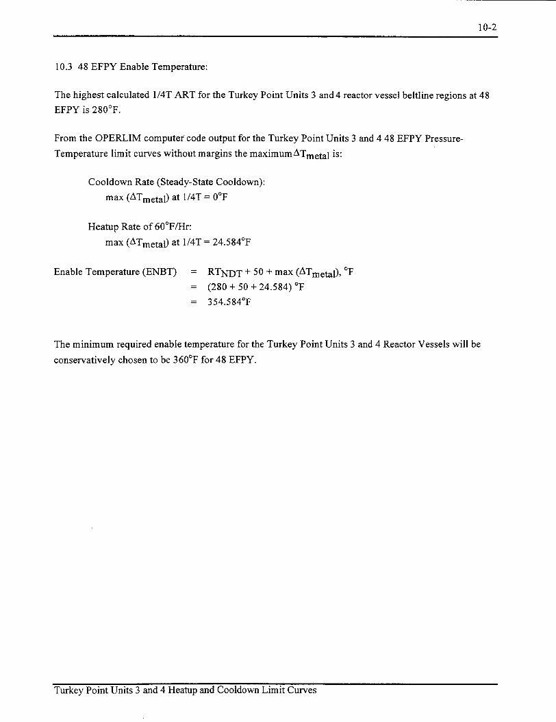
10-2
10.3 48 EFPY Enable Temperature:
The highest calculated 1/4T ART for the Turkey Point Units 3 and 4 reactor vessel beltline regions at 48
EFPY is 280'F.
From the OPERLIM computer; code output for the Turkey Point Units 3 and 4 48 EFPY Pressure
Temperature limit curves without margins the maximumATmetal is:
Cooldown Rate (Steady-State Cooldown):
max (ATmetal) at 1/4T = 00F
Heatup Rate of 60°F/Hr:
max (ATmetal) at 1/4T = 24.584°F
Enable Temperature (ENBT) = RTNDT + 50 + max (ATmetal), 'F
= (280 + 50 +24.584) 'F
= 354.5840 F
The minimum required enable temperature for the Turkey Point Units 3 and 4 Reactor Vessels will be
conservatively chosen to be 360'F for 48 EFPY.
Turkey Point Units 3 and 4 Heatup and Cooldown Limit Curves

11-1
11.0 REFERENCES
1 Regulatory Guide 1.99, Revision 2, "Radiation Embrittlement of Reactor Vessel Materials", U.S.
Nuclear Regulatory Commission, May, 1988.
2 10 CFR Part 50, Appendix G, "Fracture Toughness Requirements", Federal Register, Volume 60,
No. 243, dated December 19, 1995.
3 1997 ASME Boiler and Pressure Vessel (B&PV) Code, Section XI, Appendix G, "Fracture
Toughness Criteria for Protection Against Failure".
4 Document No. PT-ENG-SESJ-99-0118, Revision 1, "Florida Power & Light Co., Reactor Vessel
Data Turkey Point Units 3 & 4", dated February 8, 2000.
5 WCAP-863 1, "Analysis of Capsule T from the Florida Power and Light Company Turkey Point
Unit No. 3 Reactor Vessel Radiation Surveillance Program", Yanichko, S. E., et al., December
1975.
6 WCAP-7656, "Florida Power and Light Company Turkey Point Unit No. 3 Reactor Vessel
Radiation Surveillance Program", Yanichko, S. E., et al., May 1971.
7 1989 Section III, Division 1 of the ASME Boiler and Pressure Vessel Code, Paragraph NB-233 1,
"Material for Vessels".
8. Document No. PT-ENG-SESJ-99-0118, "Florida Power & Light Co., Reactor Vessel Data Turkey Point Units 3 & 4"
9. WCAP-7660, "Florida Power and Light Company Turkey Point Unit No. 4 Reactor Vessel Radiation Surveillance Program", Yanichko, S. E., May 1971.
Turkey Point Units 3 and 4 Heatup and Cooldown Limit Curves

L-2000-146
ENCLOSURE 2
Low Temperature Overpressure Protection System Setpoints,
32 and 48 Effective Full Power Years
for Turkey Point Units 3 and 4,
Westinghouse Electric Company LLC,
June 2000.

Westinghouse Electric Company, LLC Box 355 Pittsburgh Pennsylvania 15230-0355
June 29, 2000
CAW-00-1405 Document Control Desk U.S. Nuclear Regulatory Commission Washington, DC 20555
Attention: Mr. Samuel J. Collins
APPLICATION FOR WITHHOLDING PROPRIETARY INFORMATION FROM PUBLIC DISCLOSURE
Subject: "Low Temperature Overpressure Protection System Setpoints for Florida Power and Light Company for 32 EFPY and 48 EFPY for Turkey Point Units 3 and 4" [Proprietary]
Dear Mr. Collins:
The proprietary information for which withholding is being requested in the above-referenced report is further identified in Affidavit CAW-00-1405 signed by the owner of the proprietary information, Westinghouse Electric Company LLC. The affidavit, which accompanies this letter, sets forth the basis on which the information may be withheld from public disclosure by the Commission and addresses with specificity the considerations listed in paragraph (b)(4) of 10 CFR Section 2.790 of the Commission's regulations.
Accordingly, this letter authorizes the utilization of the accompanying Affidavit by Florida Power and Light Company.
Correspondence with respect to the proprietary aspects of the application for withholding or the Westinghouse affidavit should reference this letter, CAW-00-1405 and should be addressed to the undersigned.
Very truly yours,
H. A. Sepp, Manager Regulatory and Licensing Engineering
Enclosures
cc: S. Bloom/NRR/OWFN/DRPWIPDIV2 (Rockville, MD) IL
0510s.doc

CAW-00-1405
AFFIDAVIT
COMMONWEALTH OF PENNSYLVANIA:
ss
COUNTY OF ALLEGHENY:
Before me, the undersigned authority, personally appeared Henry A. Sepp, who, being by me
duly sworn according to law, deposes and says that he is authorized to execute this Affidavit on behalf of
Westinghouse Electric Company LLC ("Westinghouse"), and that the averments of fact set forth in this
Affidavit are true and correct to the best of his knowledge, information, and belief:
Henry A. Spp, Manager
Regulatory and Licensing Engineering
Sworn to and subscribed
before me this day
of 2000
Notary Public
Notarial Seal Lorraine M. Piplica, Notary Public
Monroeville Boro, Allegheny County My Commission Expires Dec. 14, 2003
0510s.doc Member, Pennsylvania Association of Notaries
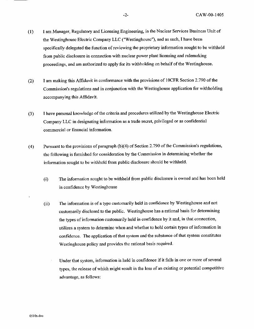
CAW-00-1405
(1) I am Manager, Regulatory and Licensing Engineering, in the Nuclear Services Business Unit of
the Westinghouse Electric Company LLC ("Westinghouse"), and as such, I have been
specifically delegated the function of reviewing the proprietary information sought to be withheld
from public disclosure in connection with nuclear power plant licensing and rulemaking
proceedings, and am authorized to apply for its withholding on behalf of the Westinghouse.
(2) I am making this Affidavit in conformance with the provisions of 1OCFR Section 2.790 of the
Commission's regulations and in conjunction with the Westinghouse application for withholding
accompanying this Affidavit.
(3) I have personal knowledge of the criteria and procedures utilized by the Westinghouse Electric
Company LLC in designating information as a trade secret, privileged or as confidential
commercial or financial information.
(4) Pursuant to the provisions of paragraph (b)(4) of Section 2.790 of the Commission's regulations,
the following is furnished for consideration by the Commission in determining whether the
information sought to be withheld from public disclosure should be withheld.
(i) The information sought to be withheld from public disclosure is owned and has been held
in confidence by Westinghouse
(ii) The information is of a type customarily held in confidence by Westinghouse and not
customarily disclosed to the public. Westinghouse has a rational basis for determining
the types of information customarily held in confidence by it and, in that connection,
utilizes a system to determine when and whether to hold certain types of information in
confidence. The application of that system and the substance of that system constitutes
Westinghouse policy and provides the rational basis required.
Under that system, information is held in confidence if it falls in one or more of several
types, the release of which might result in the loss of an existing or potential competitive
advantage, as follows:
0510s.doc
-2-

CAW-00-1405
(a) The information reveals the distinguishing aspects of a process (or component,
structure, tool, method, etc.) where prevention of its use by any of
Westinghouse's competitors without license from Westinghouse constitutes a
competitive economic advantage over other companies.
(b) It consists of supporting data, including test data, relative to a process (or
component, structure, tool, method, etc.), the application of which data secures a
competitive economic advantage, e.g., by optimization or improved
marketability.
(c) Its use by a competitor would reduce his expenditure of resources or improve his
competitive position in the design, manufacture, shipment, installation, assurance
of quality, or licensing a similar product.
(d) It reveals cost or price information, production capacities, budget levels, or
commercial strategies of Westinghouse, its customers or suppliers.
(e) It reveals aspects of past, present, or future Westinghouse or customer funded
development plans and programs of potential commercial value to Westinghouse.
(f) It contains patentable ideas, for which patent protection may be desirable.
There are sound policy reasons behind the Westinghouse system which include the
following:
(a) The use of such information by Westinghouse gives Westinghouse a competitive
advantage over its competitors. It is, therefore, withheld from disclosure to
protect the Westinghouse competitive position.
(b) It is information which is marketable in many ways. The extent to which such
information is available to competitors diminishes the Westinghouse ability to
sell products and services involving the use of the information.
0510s.doc
-3-

CAW-00-1405
(c) Use by our competitor would put Westinghouse at a competitive disadvantage by
reducing his expenditure of resources at our expense.
(d) Each component of proprietary information pertinent to a particular competitive
advantage is potentially as valuable as the total competitive advantage. If
competitors acquire components of proprietary information, any one component
may be the key to the entire puzzle, thereby depriving Westinghouse of a
competitive advantage.
(e) Unrestricted disclosure would jeopardize the position of prominence of
Westinghouse in the world market, and thereby give a market advantage to the
competition of those countries.
(f) The Westinghouse capacity to invest corporate assets in research and
development depends upon the success in obtaining and maintaining a
competitive advantage.
(iii) The information is being transmitted to the Commission in confidence and, under the
provisions of 10CFR Section 2.790, it is to be received in confidence by the Commission.
(iv) The information sought to be protected is not available in public sources or available
information has not been previously employed in the same original manner or method to
the best of our knowledge and belief
(v) The proprietary information sought to be withheld in this submittal is that which is
appropriately marked in "Low Temperature Overpressure Protection System Setpoints
for Florida Power and Light Company for 32 EFPY and 48 EFPY for Turkey Point Units
3 and 4" being transmitted by Florida Power and Light Company letter and Application
for Withholding Proprietary Information from Public Disclosure, to the Document
Control Desk, Attention: Mr. Samuel J. Collins. The proprietary information as
051 Os.doc
-4-

CAW-00-1405
submitted for use by Turkey Point Units 3 and 4 is expected to be applicable in other
licensee submittals in response to certain NRC requirements.
This information is part of that which will enable Westinghouse to:
(a) Provide documentation of the methods for determination of equipment
operability and acceptable calibration of the noted COMS setpoint development.
(b) Provide the specific design information related to the parameters that are
considered for the COMS setpoint development.
(c) Assist the customer to obtain NRC approval.
Further this information has substantial commercial value as follows:
(a) Westinghouse plans to sell the use of similar information to its customers for
purposes of meeting NRC requirements for licensing documentation.
(b) Westinghouse can sell support and defense of the technology to its customers in
the licensing process.
Public disclosure of this proprietary information is likely to cause substantial harm to the
competitive position of Westinghouse because it would enhance the ability of
competitors to provide similar calculation, evaluation and licensing defense services for
commercial power reactors without commensurate expenses. Also, public disclosure of
the information would enable others to use the information to meet NRC requirements
for licensing documentation without purchasing the right to use the information.
The development of the technology described in part by the information is the result of
applying the results of many years of experience in an intensive Westinghouse effort and
the expenditure of a considerable sum of money.
051 Os.doc
-5-

CAW-00-1405
In order for competitors of Westinghouse to duplicate this information, similar technical
programs would have to be performed and a significant manpower effort, having the
requisite talent and experience, would have to be expended for developing testing and
analytical methods and performing tests.
Further the deponent sayeth not.
0510s.doc
-6-

Westinghouse Electric Company
Nuclear Services
Box 355 Pittsburgh, Pennsylvania 15230-0355
6/30/00To: Steve Collard
FPL, Nuclear Division Juno Beach, FL 33408 (561)694-4175
CERTIFICATION OF CONFORMANCE
Turkey Point Units 3 and 4 - 32 EFPY and 48 EFPY LTOP Setpoints, with 3.05 Sec. Stroke Open Time
Westinghouse hereby certifies that the Turkey Point Units 3 and 4 - 32 EFPY and 48 EFPY LTOP Setpoints a. were generated and verified in compliance with the Westinghouse Policies and
Procedures Manual (Nuclear Services and Projects Edition) and implementing procedures, instructions and guidance; and
b. satisfy the requirements of Sales Order No.: 4884 C/N 000, June 8, 2000.
Westinghouse Quality Systems certifies functional verification of the above procedures, via the Westinghouse internal assessment program, to its NRC accepted Quality Management System (QMS) document, Revision 3, which complies with the ISO 9001 standard and 10CFR50, Appendix B.
I.ao. , SupervisoQualingineer Quality Systems I
T. A. Mille/, Senior Engineer
Plant Op rations and Equipment Diagnostics
Recommended