Wattmeter Project Presentation
David Box, Ali Alsuliman, Buck Fife, Matthew Kent, Dylan Brams
Introduction
Presentation Organization:1. Introduction2. Need, Motivation, Objective, and Alternatives3. Requirements and Approach4. Design
a) Sensingb) Power Provision and Enclosurec) Microcontroller
5. Team Description6. Conclusion
Problem and Motivation
Reporting Power Consumption• Monitoring power consumption not currently in broad use.• Residential consumption tends to be ‘unconscious.’• Industry moving towards more flexible pricing based on time
of consumption– Price of electricity, as with power in general, is rising quickly.
• Some appliances have surprisingly high passive power consumption
Alternatives
There are many existing solutions• Expensive• Not consumer-friendly• Technically packaged
DIY community also active• Few using circuit boards• Few go to extreme of surface-mounted hall effect sensors• All pre-designed circuits found did not export data or have
much flexibility.
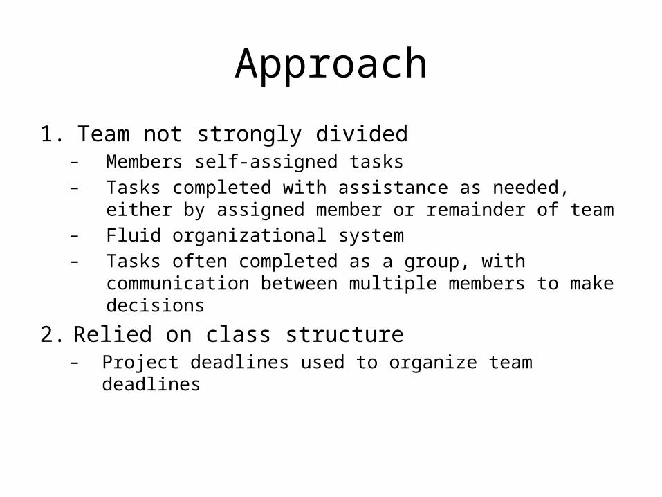
Approach
1. Team not strongly divided– Members self-assigned tasks– Tasks completed with assistance as needed, either by assigned
member or remainder of team– Fluid organizational system– Tasks often completed as a group, with communication between
multiple members to make decisions
2. Relied on class structure– Project deadlines used to organize team deadlines
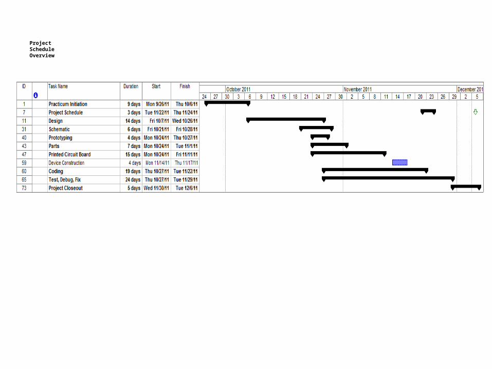
ProjectScheduleOverview
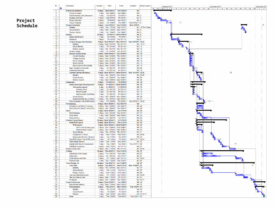
ProjectSchedule
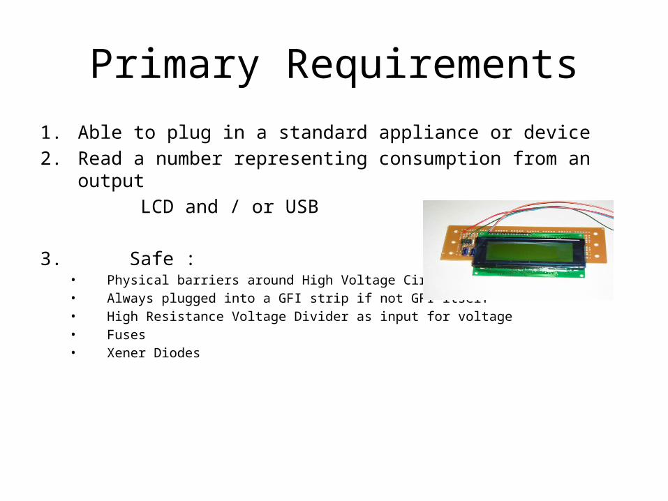
Primary Requirements1. Able to plug in a standard appliance or device2. Read a number representing consumption from an output LCD and / or USB
3. Safe :• Physical barriers around High Voltage Circuit• Always plugged into a GFI strip if not GFI itself• High Resistance Voltage Divider as input for voltage• Fuses• Xener Diodes
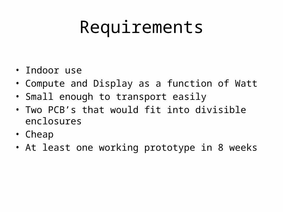
• Indoor use• Compute and Display as a function of Watt• Small enough to transport easily• Two PCB’s that would fit into divisible enclosures• Cheap • At least one working prototype in 8 weeks
Requirements
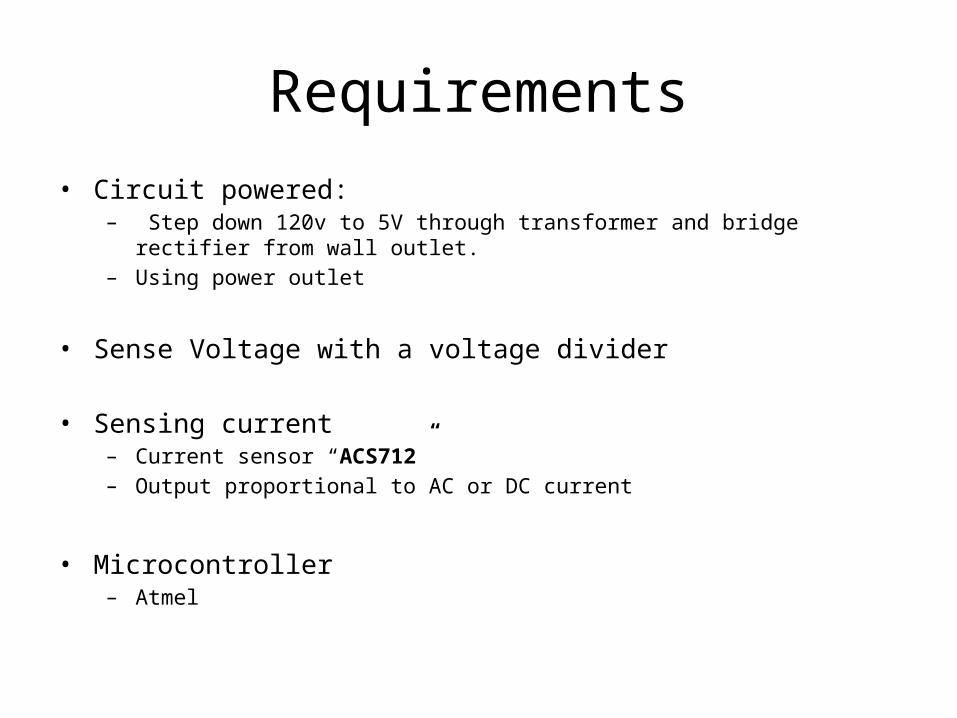
Requirements• Circuit powered:
– Step down 120v to 5V through transformer and bridge rectifier from wall outlet.– Using power outlet
• Sense Voltage with a voltage divider
• Sensing current – Current sensor “ACS712”– Output proportional to AC or DC current
• Microcontroller– Atmel
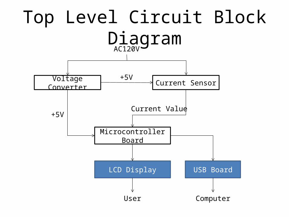
Top Level Circuit Block Diagram
Current SensorVoltage Converter
AC120V
+5V
Microcontroller Board
USB BoardLCD Display
User Computer
+5VCurrent Value

Sensing Subsystems
Power CalculationsThe wattmeter calculates power consumption based on peak to peak current measurements and nominal voltage values.
Real Power (watts)
Apparent Power (VA)
Cos(pf)
Resistive Load Out of Phase Load Switching Load
Assumes Voltage andCurrent are in Phase
Assumes asinusoidal waveform
Nominal ignores 5% variance
Measured
Power calculations based on current measurements alone disregards the complex power component of inductive loads (fans, motors, etc…). Assuming a sinusoidal current ignores the efficiency of switching power supplies.
Sensing Subsystems
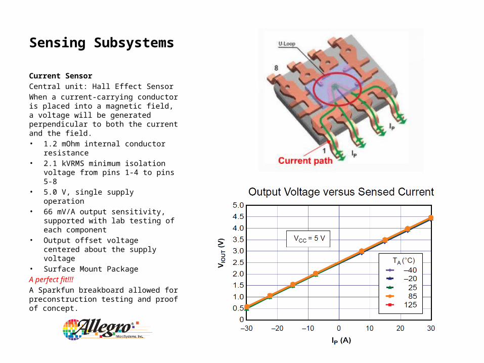
Current SensorCentral unit: Hall Effect SensorWhen a current-carrying conductor is placed into a magnetic field, a voltage will be generated perpendicular to both the current and the field.• 1.2 mOhm internal conductor
resistance• 2.1 kVRMS minimum isolation
voltage from pins 1-4 to pins 5-8• 5.0 V, single supply operation• 66 mV/A output sensitivity,
supported with lab testing of each component
• Output offset voltage centered about the supply voltage
• Surface Mount PackageA perfect fit!!!A Sparkfun breakboard allowed for preconstruction testing and proof of concept.
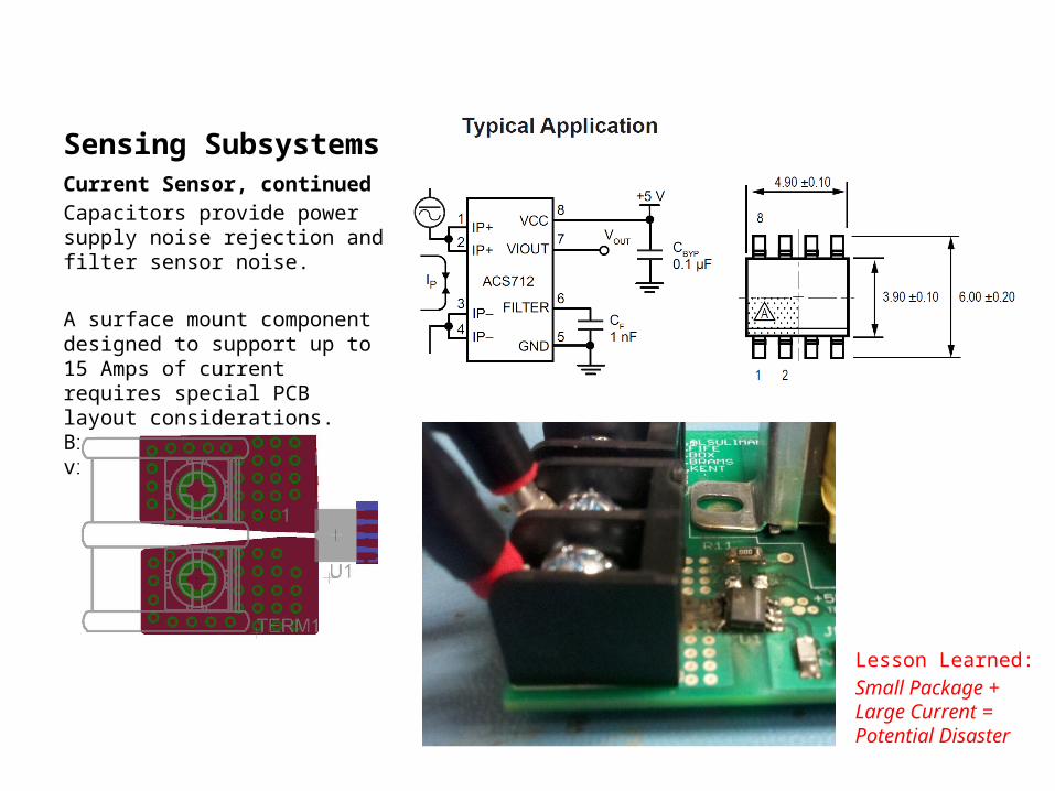
Sensing SubsystemsCurrent Sensor, continuedCapacitors provide power supply noise rejection and filter sensor noise.
A surface mount component designed to support up to 15 Amps of current requires special PCB layout considerations. Big pads, lots of small vias.
Lesson Learned:Small Package + Large Current = Potential Disaster
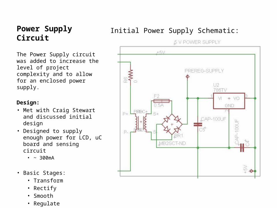
Power Supply CircuitInitial Power Supply Schematic:
The Power Supply circuit was added to increase the level of project complexity and to allow for an enclosed power supply.
Design:• Met with Craig Stewart and
discussed initial design• Designed to supply enough
power for LCD, uC board and sensing circuit
• ~ 300mA
• Basic Stages:• Transform• Rectify• Smooth• Regulate
Power Supply Circuit TestingTwo problems accounted for the majority of problems:
Problem 1• The Power Supply would supply 4.98V when
disconnected from the microcontroller but would dip to 4.6V when the LCD and board were connected.
Explanation:• The capacitance of the smoothing section of
the power supply was too low. More capacitance was needed to smooth the input to the voltage regulator
Solution:• A 1000uF electrolytic capacitor was added
in parallel before the rectifier and the supply successfully powered the board.
• Note: The filtering capacitor was left off the regulator to remove variables in testing. It was not needed due to the large capacitance on the uC board.
Problem 2• The Power Supply when properly
mounted and connected to the outlet produced no voltage.
Explanation:• The board and the mounts of the
transformer were shorting to the box through the mounting screws
Solution:• A plastic sheet was added underneath to
isolate the board• The Transformer mounts were removed to
prevent any connection
Fusing
High Side Fusing:• Fusing was added to prevent damage to
the device under test and power board
• Added in series to the hot of the wall and the in to the current sensor
• Inline package was used to save space on board
• 10A, 1¼” x 1/4“, fast-acting , fuse used as specified in the project requirements
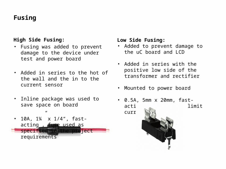
Low Side Fusing:• Added to prevent damage to the uC board
and LCD
• Added in series with the positive low side of the transformer and rectifier
• Mounted to power board
• 0.5A, 5mm x 20mm, fast-acting, fuse used to limit current

Final Power Supply Schematic
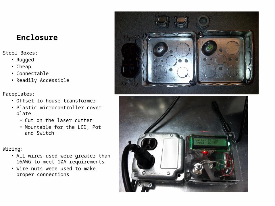
Enclosure
Steel Boxes:• Rugged• Cheap• Connectable• Readily Accessible
Faceplates:• Offset to house transformer• Plastic microcontroller cover plate
• Cut on the laser cutter• Mountable for the LCD, Pot and
Switch
Wiring: • All wires used were greater than 16AWG
to meet 10A requirements• Wire nuts were used to make proper
connections
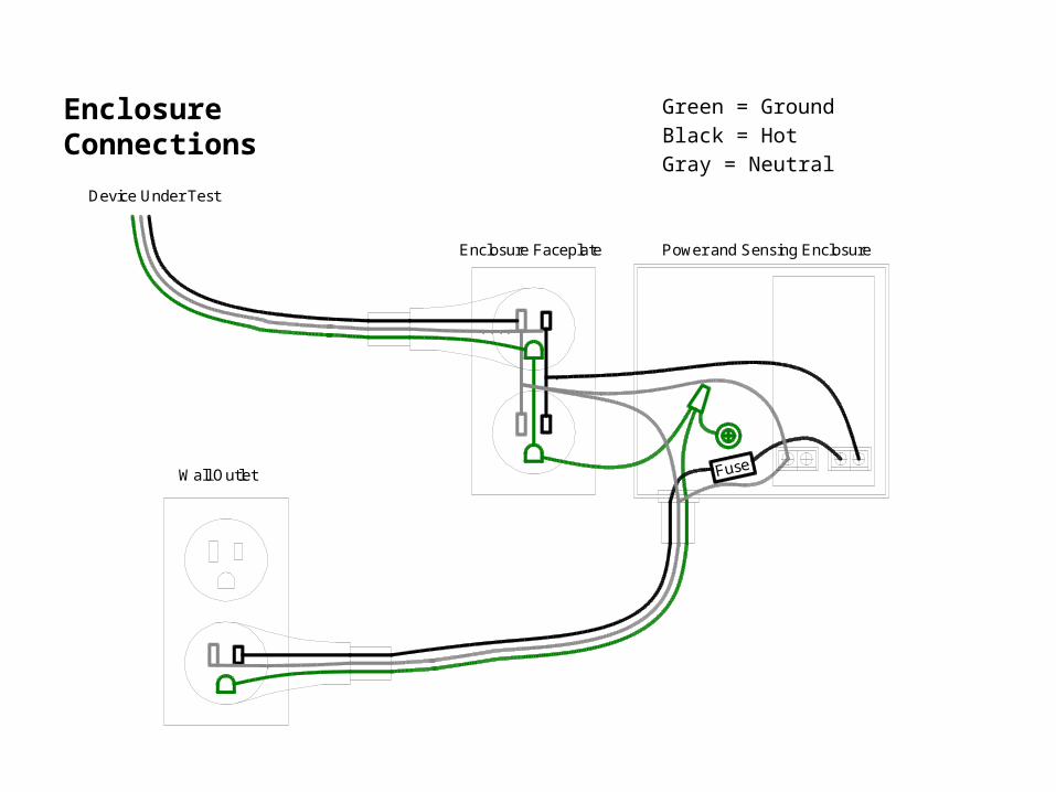
Enclosure Connections
Wall Outlet Fuse
Device Under Test
Power and Sensing EnclosureEnclosure Faceplate
Green = GroundBlack = HotGray = Neutral
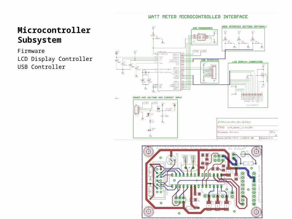
Microcontroller SubsystemFirmwareLCD Display ControllerUSB Controller
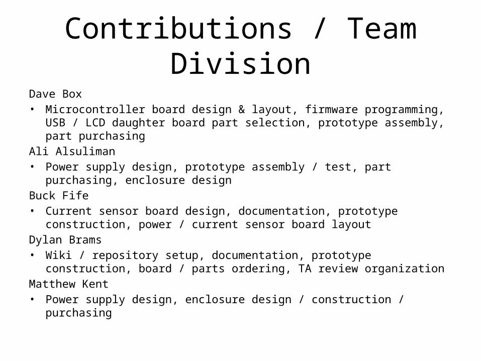
Contributions / Team DivisionDave Box• Microcontroller board design & layout, firmware programming, USB / LCD
daughter board part selection, prototype assembly, part purchasingAli Alsuliman• Power supply design, prototype assembly / test, part purchasing, enclosure designBuck Fife• Current sensor board design, documentation, prototype construction, power /
current sensor board layoutDylan Brams• Wiki / repository setup, documentation, prototype construction, board / parts
ordering, TA review organizationMatthew Kent• Power supply design, enclosure design / construction / purchasing

Lessons Learned
Post Mortem Meeting
References
Energy Consumption• http://www.energysavers.gov/your_home/appliances/index.cfm/mytopic=10040; Energy consumption of common
appliances• http://www.keysenergy.com/appliances.php;Monthly energy consumption of household appliancesCurrent Sensing• http://en.wikipedia.org/wiki/Power_factor;Waveform images• http://content.honeywell.com/sensing/prodinfo/solidstate/technical/chapter2.pdf; Background for hall effect
sensors• http://www.allegromicro.com/Products/Current-Sensor-ICs/Zero-To-Fifty-Amp-Integrated-Conductor-Sensor-ICs/ACS
712.aspx; Current Sensor Information
• http://www.sparkfun.com/products/8882; Current Sensor Breakout Board used for prototyping.• http://www.te.com/catalog/bin/TE.Menu?M=MENU&ID=10785&LG=1&I=13; Terminal Block Manufacturer WebsitePower Supply• http://www.ehow.com/how_4840923_wire-step-down-transformer.html; Basic Tutorial On wiring a step-down
transformers• http://www.eleinmec.com/article.asp?16; Tutorial on building a 5VDC power supply• http://www.te.com/catalog/menu/en/17718?BML=10576,17533; List of cable connectors researched• http://search.digikey.com/us/en/products/64600001003/WK6244-ND/151822; Fuse holder at Digikey• http://power-topics.blogspot.com/2011/02/inrush-currents-external-fusing-on.html; Article on Highside fusing• http://www.tpub.com/neets/book3/8e.htm; Identification of fusesPeople• Craig Stewart, Electrical Engineer, The Boeing Company - Consulted with to construct the power supply circuit• Kevin Ting, Electrical Engineering Student, University of Washington - Matt’s lab partner and cowriter of LCD source
code posted on the wiki but unused in the project• Chris Clark, Computer Engineering Student, Portland State University - Cut the microcontroller cover plates on the
school laser cutter
References
Microcontroller• http://www.avrfreaks.net/ - tutotials on ADC conversions, and LCD connections• http://www.evilmadscientist.com/article.php/avrserial Source of knowledge on USB communication
and USB source code.• http://jump.to/fleury Source of LCD library code• ATMEL Atmega datasheet for the ATmega328P
ToolsSoftware• Easily Applicable Graphical Layout Editor (EAGLE) Version 5.11.0 for windows.• Ltspice IV Version 4.04q• Microsoft Office Software Suite• Redmine Wiki Site• Subversion Document Revision Control and Repository• Autocad
Lab Equipment• Tektronix MSO 4054 Mixed Signal Oscilloscope• Tektronix AFG 3252, Dual Channel Arbitrary Function Generator• Gwinstek GPS-3303, Laboratory DC-Power Supply
Hardware• Soldering tools provided in the PSU ECE Capstone Lab• Drill Press in the ECE Capstone Lab• PSU Laser Cutting Device
Recommended