WATER CONTROL IN UNDERGROUND MINES- GROUTING OR DRAINAGE? by V. STRASKRABA, and S. EFFNER
TRC HYDRO-GEO CONSULTANTS 165 S. UNION BLVD., SUITE 400 LAKEWOOD, COLORADO, USA 80228
ABSTRACT
Mine dewatering and grouting are the two most common methods of ground water control in underground mining. Both methods have advantages and limitations and their applications typically depend on a variety of factors. These factors include the hydrogeologic characteristics of the mine, the depth of the mine and mining methods, and the potential environmental consequences of mining, including discharge of water pumped from the mine.
In this paper, the authors analyze the potential application of each of the water control methods under various conditions, the advantages and limitations of each water control method, and the potential environmental impacts.
It appears that a complete analysis of site characteristics combined with the consideration of mining methods and potential environmental consequences has not been used by many mines to determine the most appropriate water control method. A variety of methods and tools can be utilized to analyze ground water inflow into the mine, the long-term water quality that will be discharged from the mine or from dewatering wells, and for the selection of the most efficient water control methods. These methods include analytical calculations, numerical ground water flow models, and geochemical models to assess the long-term chemistry of mine waters.
The authors demonstrate with several case histories how the design of water control methods, which are based on the consideration of all aspects of the project, can successfully improve mining conditions (safety and efficiency), and reduce the environmental impacts on surface and ground water resources.
INTRODUCTION
Numerous underground mines, have been developed in the last 10 years, or are planned to be developed in the near future in the United States. Most of these mines concentrate on recovery of gold, zinc, and copper. Although many of these mines are located in the arid or semiarid areas of the western United States, water related problems are of great concern at all of the mines. The presence of ground water in a mine has adverse impacts on mine production, ground control, and safety. Strict environmental regulations for the mining industry are being
IMWA SYMPOSIUM JOHANNESBURG 1998 195
IMWA Proceedings 1998 | © International Mine Water Association 2012 | www.IMWA.info
Reproduced from best available copy

implemented by state and federal regulatory agencies, and the protection of surface and ground water resources is one of the main objectives of the mining regulations.
The recent decline in the price of mineral commodities, and strict environmental regulations are leading to the implementation of more sophisticated water control methods during mining operations. The water control methods are aimed at the improvement of mining efficiency and safety, reduction of costs of mining and mine reclamation, and at the limitation of the probable hydrologic consequences of the mining activities. A well designed and implemented water management control system for an underground mine should consider the climatic, hydrologic and hydrogeologic characteristics of the mine area, the mining methods and the depth of the mine, and the potential environmental impacts of the mining operation during and after the completion of the production.
WATER CONTROL METHODS
The main objective in the control of water in underground mines is to develop efficient and safe working conditions and to limit the environmental impacts on surface and ground water resources. Ground water control methods can consist of prevention, (the limitation of water inflow into the mines and/or pumping of water prior to entering a mine) or, pumping from the mine. Our experience from many mining projects indicates that well-designed and executed mine water control programs can substantially improve mining conditions by increasing the efficiency of rubber-tired vehicles, creating a safer environment by working in dry, instead wet conditions, and, therefore, decrease the cost of operations. Considerable cost savings can be realized in a mine with an adequate water control system. Examples of cost savings include the use of dry hole blasting agents, increased efficiency of mining, and decreasing costs of pumping and water treatment.
There are many potential mine water control methods, however, only a few of them are practically and economically applicable for underground mines. The following are the most applicable methods used for water control in underground mines:
• Impermeabilization at ground surface; • Ground freezing; • Grouting, and; • Mine drainage.
Ground surface impermeabilization is not a common method of mine water inflow control in the arid conditions of the western United States, because major surface water streams are typically not present. However, this method was used with success in several mines worldwide. In the Neves-Corvo Mine in Portugal (Carvalho, et al, 19901'') sealing of a river course with concrete, reinforced with steel mesh and anchors, and protection of river banks by shotcrete substantially reduced water inflow to the mine. Another successful impermeabilization of river course flowing over a subsidence impacted area was reported at the Konkola Mine in Zambia (Freeman, 1970[21). At this mine, a sublevel caving mining method was used, and local stream beds were filled with tailings to seal the cracks developed by subsidence. Later, more environmental friendly methods for surface stream sealing were proposed for this mine
196 IMWA SYMPOSIUM JOHANNESBURG 1996
IMWA Proceedings 1998 | © International Mine Water Association 2012 | www.IMWA.info
Reproduced from best available copy

(Mulenga, 1993131). However, the prohibitive cost and uncertainty as to how efficient the sealing would be, prevented the completion of the project.
Ground freezing can be a very efficient method of ground water control in certain hydrogeologic conditions. Ground freezing has been successfully used on many shaft sinking projects, especially for coal and potash mines. Recently, an extensive ground freezing program has been proposed for ground water control at an open pit mine in Canada, but the project was not realized for economical reasons (Placquet, 199714~. To our knowledge, this method has not been used for ground water control in underground mines, with the exception of shaft sinking.
Grouting practices for soil and rock stabilization and ground water control have a long history. From the simple injection of bentonite and lime slurry for soil stabilization in the first part of the 19'" century to the sophisticated injection of chemical grouts for historical building restoration and ground water control. Most of the applications of grouting technology in the mining and tunneling industry use cement, and cement - clay grouts. There are many technical papers describing the successful application of grouting methods in mining and tunneling (Kipko at a!, 1993151; Heinz, 1997161; Nel, 1997[71). However, only a few describe the limitations or failures of grouting methods.
The application of cement-based grouts is more common in the mining and tunneling industry than use of other types of grouts. Numerous vertical shafts have been sunk under the cover of grouting. Methods of pre-cementation have been used extensively in South Africa, the United Kingdom, the former USSR, and also on several coal mine shafts in the eastern United States. Grouting from the bottom of shafts during sinking is a common practice in the industry for overcoming sections with poor ground conditions or excessive ground water inflow.
Mine dewatering is the most common method of water control in underground mines. Dewatering methods for underground mines can range from the relatively simple collection of water seeping into the mine from fractures or roof bolts, to more complex drilling of dewatering wells from the ground surface, drilling of drainage boreholes from within the mine, or mining of drainage galleries.
Dewatering of mines by the use of vertical wells drilled from the surface is a common practice, especially in open pit mines. The advantage of this system of dewatering is drainage ahead of mining, discharge of clean water, and practically no interference with the mining operation. Disadvantages of this method are the cost of drilling and pumping, limitations in drawdown achieved, and cost-effectiveness in dewatering both aquifers oflow permeability, and prevalently vertical-fractured rock masses. Dewatering wells from the surface could not effectively dewater several underground mines in Nevada, where this method of dewatering was tried and could be used only in combination with the in-mine drilled drainage boreholes.
The drilling of deep dewatering wells from the ground surface which are capable of pumping large volumes of water has become quite common in the last several years in the western United States. There are at least three new underground gold mines in the western United States where deep dewatering wells drilled from the ground surface are the main drainage system. These mines, located in Nevada (Meikle, West Leeville, and Turquoise Ridge), use large diameter wells (25 to 40 em) and submersible pumps capable of pumping up to I 00 IIsee from depths greater than 700 meters.
Drainage boreholes drilled above the stopes, or into the hanging wall from the access drifts are very probably the most common method of mine drainage. These boreholes, if combined with delineation or definition drilling, can be the most cost effective dewatering
IMWA SYMPOSIUM JOHANNESBURG 1998 197
IMWA Proceedings 1998 | © International Mine Water Association 2012 | www.IMWA.info
Reproduced from best available copy
method. Drainage boreholes are typically drilled up to an angle of+ 10 to +55 degrees, and the orientation of the boreholes should be based on mining plans, orientation of main fracture systems, and the size of stopes. Boreholes can be drilled with coring or percussion bits. In strongly fractured or weathered zones, it may be necessary to insert plastic or steel casing into the boreholes to prevent caving. Most of the drainage boreholes are installed with a 4 to 5-cm diameter plastic (PVC) casing. This type of mine drainage has been quite successful in Deep Star and Rosebud underground gold mines in Nevada, and the Lamefoot and K 2 mines in Washington State. In-mine drainage boreholes are also the main method of dewatering in the Konkola Mine in Zambia, which is considered to be one of the wettest mines in the world.
Drainage galleries have not been used extensively for mine dewatering in last 10 years, mainly because of the cost. A very unique drainage tunnel was completed at the tum of the century in western Colorado. This tunnel, the Yak Tunnel, is about 6 km long and drains the entire section (10km2
) of the Leadville historical mining district. The continuing discharge from this tunnel of about 20 lfsec of highly acidic water brought serious environmental impacts. Similar tunnel was completed in Idaho Springs, Colorado (Argo Tunnel). The longest drainage adit is very probably the Ferdinand adit in Kremnica, Slovakia, which is 18 km long (Straskraba, 1983)l81•
SELECTION OF WATER CONTROL METHODS
Selection of the most appropriate method of water control for a particular mine should be based on a comprehensive study of local climatic, hydrologic, hydrogeologic characteristics of the mine area, and should consider the mining methods, and depth of the mine. The environmental considerations should include not only the potential impacts on surface and ground water resources during mining, but also the long-term impacts on water quality after the completion of mining. Cost considerations should be a part of any design of mine drainage. The cost study should consider not only the expenses related to drainage, sealing, or grouting, but also the potential expenses for water treatment and discharge, and other environmental consequences.
A study of the best method for mine water control should be based on an analysis of local climatic conditions and the development of a water balance for the mine area. This study should estimate how much water is available for the ground water system recharge, and how much water can be released from storage during the mining operation. The presence of major surface water bodies in the mine area should be analyzed, and the potential for hydraulic connection between the source of surface water and the mine should be assessed. The mining method being considered for application and the depth of the mine are important factors in the assessment of potential seepage into the mine from a surface water source. Important factors for the estimation of subsidence effects on hydraulic connection between surface water resources and an underground mine include mining methods, whether the mine is caved or backfilled, and the type and method of backfill placement. Hydrogeologic characteristics of the mine area have a great impact on the selection of water control methods. The presence of major aquifers in the mine overburden, or the existence of a highly conductive water-bearing orebody should be considered. Sudden inrushes of water into an underground mine are often caused by the presence of major geological structures. An investigation of the hydraulic characteristics of major structures, and faults in particular, is necessary for the selection of a water control method. Faults often act as
198 IMWA SYMPOSIUM JOHANNESBURG 1998
IMWA Proceedings 1998 | © International Mine Water Association 2012 | www.IMWA.info
Reproduced from best available copy

hydraulic conduits in the shear zone along the fault, but can also act as hydraulic barriers perpendicular to the fault due to the presence of mylonite and clay particles.
Calculation of the probable water inflow into the mine should be a part of any study for mine water control. Analytical methods, as for example the "Large Well" method adapted for the mining application by Russian hydrogeologists (Klimentov et al, 1957[91, and others), are a good first step in the mine inflow assessment. For some mines with relatively simple hydrogeologic conditions, analytical methods may be adequate for the mine water inflow estimates. In more complex hydrogeologic conditions, where significant aquifers and major faults are present, or where potential impacts of mine drainage on surface and/or ground water resources is of the concern, the application of numerical computer models should be considered. Simulation of ground water inflow into a mine should indicate from which strata and how much water would be flowing into the mine workings at various stages of the mining activities. An example is shown on Figure 1. This figure presents the results of an extensive simulation of ground water inflow into a planned zinc-copper underground mine in Wisconsin, with an emphasis on the potential impacts on a glacial aquifer, surface streams, lakes, and wetlands.
Potential environmental impacts of mine drainage on surface streams, including depletion of stream flows, and impacts on adjudicated water rights, are of great concern in the arid climatic conditions of the western United States. The aspects of potential impacts should be considered in the selection of water control methods. Protection of major aquifers which are used by others for water supply is an important consideration in the selection of a water control method. Extensive pumping from a major aquifer can cause substantial drawdown in a large area and impact numerous water users. This may substantially increase the cost of the mining operation, and can be a difficult obstacle in the mine permitting process.
The estimated volume of water which will need to be pumped has to balance the development of conditions for efficient and safe mining while limiting impacts on surface and ground water resources.
Included in the evaluation of impacts to surface and ground water resources should be an estimation of the potential water quality of discharge from the mine, and the post-mining ground water quality. This type of study would be based on background water quality data, the geology of the deposit, geochemical testing (Humidity Cell, Acid-Base Accounting, and Meteoric Water Mobility Tests) and prediction modeling. Several software packages are available for geochemical modeling including PHREEQE and MINTEQA2 which have been widely accepted by regulatory agencies in the United States.
EXAMPLES OF WATER CONTROL METHODS
The water control methods for an underground mine should be selected in the stages of pre-feasibility and feasibility studies. Mine water control can contribute substantial costs to the mining operation, and the environmental consequences for poorly designed water control can be costly for many years after mine closure.
The following text presents several examples of well thought out and designed water control methods for a few mines already in production, and for several mines in the development and planning stages:
Deep Star Underground Gold Mine in Nevada: This relatively small mine is located on the Carlin Trend in Nevada, near the Post/Bet.lC open pit where more than 4,100 Usee of water is
IMWA SYMPOSIUM JOHANNESBURG 1998 199
IMWA Proceedings 1998 | © International Mine Water Association 2012 | www.IMWA.info
Reproduced from best available copy

pumped from surface perimeter wells. Because of the proximity of the Deep Star Mine to the highly water-bearing strata in the open pit area, some hydrogeologists believed that dewatering wells from the surface would be necessary for the underground mine drainage, although available packer test permeability data performed in geotechnical boreholes indicated much lower hydraulic conductivity in the underground mine area. The first deep dewatering well had a low yield and pumping from this well was abandoned. The underground mine is being adequately dewatered by in-mine drainage boreholes (Figure 2), and the total mine inflow is less than 10 IIsee (Clode, 1997[1°1). Analytical calculations of probable ground water inflow into the mine proved to be more accurate than finite-element computer modeling performed for this mine.
Turquoise Ridge Underground Gold Mine in Nevada: This mine is in the first phase of production. Two shafts were sunk through highly permeable (3x10"3 em/sec) basalt up to 180 meters deep, and through moderately permeable (l.Sx104 em/sec) homfel and marble to 350 meters depth, and completed in metamorphic sediments with low permeability (S.0x10·5 em/sec at a depth over 700 meters. Shaft sinking was completed under the cover of three dewatering wells, without any significant ground water inflow into the shafts during the sinking (Barker at al, 19971111). The dewatering wells were up to 700 meters deep and pumped initially up to 86 IIsee. Figure 3 presents the current status the of water table which is depressed by pumping from three wells. It seems that the surface dewatering wells are not able to lower the water table adequately in the lower permeable strata for the initiation of the ore production on the 900 Level (274 meters). Grouting above the stopes and drilling of angled or vertical boreholes is being tested and considered for additional dewatering. Recommendations for mine dewatering, and for the shaft sinking phase of the project in particular, were based on finite-difference (MOD FLOW) computer simulation.
Meikle Underground Gold Mine in Nevada: This mine is in an early stage of development, and the mine drainage was so far accomplished by dewatering wells from the surface. In mine drainage boreholes are considered at a later stage of mining.
West Leeville Underground Gold Mine in Nevada: Proposed mine with a consideration of mine drainage by wells from the surface. Test well was completed and tested for permeability of water bearing strata. Packer permeability tests were performed at the shaft pilot borehole.
Rosebud Underground Gold Mine in Nevada: Ground water inflow calculations for this mine were based on an analytical method ("Large Well" Method), and on a water balance analysis. The potential inrush of ground water where the decline crossed a major fault was accurately predicted and the pilot boreholes drilled ahead of decline drifting were adequate for water control. Mine dewatering is handled by the drilling of drainage/definition boreholes and no major problems have been encountered during mine development and production. In-mine drainage by gravity flow from boreholes is facilitated by pumping of water from several water supply wells in the general mine area, even though these wells are located on the other side of a major structure from the mine.
Kensington Underground Gold Mine in Alaska: This mine is in a development stage and production is likely to be initiated in the near future. Calculations of the probable water inflow into the mine during production were based on a water balance method and on analytical calculations of the potential inflow along major faults. The current mine dewatering program is based on the drilling of drainage/definition boreholes into the hanging wall and into several water-bearing structures. Grouting of fracture zones and several major water-bearing structures was recommended and is being considered.
200 IU\AIA e.vuonc:;.IIIM JOHANNESBURG 1998
IMWA Proceedings 1998 | © International Mine Water Association 2012 | www.IMWA.info
Reproduced from best available copy
Lamefoot and K 2 Underground Gold Mines in Washington State: These two mines have relatively low ground water inflow , and water control is handled by drilling drainage boreholes and grouting. Grouting of boreholes with a discharge of water of more than 0.06 IIsee per borehole was imposed on the mining company by a federal regulatory agency for environmental protection. Calculations of the probable inflow of water into these two mines was based on a water balance analysis and on analytical methods.
Crandon Untl-;:rground Zinc-Copper Mine, in Wisconsin: This mine is in a feasibility study and permitting stage, and is located in a state with the most strict environmental law in the United States. Extensive computer modeling has been performed to support the conclusion that mining and mine dewatering would have minimal impact on the local surface and ground water resources. The results of computer simulations of the probable ground water inflow from various strata are presented on Figure 1. The overburden of this deposit is formed by a regional aquifer in glacial materials. These materials are underlain by low permeable clays and saprolite at the top of the bedrock. The predicted inflow into the mine is only about 37 to 80 IIsee, and the mine drainage would not create any insurmountable difficulties. However, the potential environmental consequence of impacting the glacial aquifer, the streams, lakes, and wetlands, and the need to treat and discharge the water pumped from the mine at a distant location, led to an interesting water control system. The potential reduction of permeability by extensive grouting of the weathered top of the bedrock (which is located within the proposed crown pillar) was proposed and tested. Boreholes drilled from the ground surface to a depth of 80 meters were used for grouting a cement curtain, approximately 1 0 meters thick, at the top of the bedrock. Results of test grouting, with the use of Portland cement for primary grouting, and with the application of ultrafine cement grout for the secondary grouting, indicated that grouting boreholes at a distance of 3 meters from each other could reduce the original hydraulic conductivity of 2x 1 o·3 em/sec to 9xlo·' em/sec, and could reduce the calculated vertical seepage by up to 95 percent. It is anticipated that the drilling and grouting from the underground drift will be even more efficient than grouting from the ground surface because of the mostly vertical fracture systems. The verification of the reduced permeability was accomplished by repeated packer permeability testing before and after grouting, and by drilling of several verification boreholes, from which core samples were recovered. The proposed grouting program is shown on a typical cross section as Figure 4.
CONCLUSION
The above presented practical examples of water management practices in different underground mines located in various climatic zones, and with various hydrogeologic characteristics indicate that the design of water control methods is very site-specific and depends on many factors.
Dewatering wells from the surface can be very effective for the first phase of mine development, during shaft sinking, and development drift mining, if the hydraulic conductivity of the drained strata is higher than about lxlO"" em/sec . However, wells from surface usually can not drain sufficiently the orebody if numerous faults are present, or if the permeability of the rock strata decreases with depth, which is typical in deeper mines. Advantage of dewatering wells is that mine drainage can be initiated ahead of mining, and that the quality of the pumped water is not impacted by the mining activities.
IMWA SYMPOSIUM JOHANNESBURG 1998 201
IMWA Proceedings 1998 | © International Mine Water Association 2012 | www.IMWA.info
Reproduced from best available copy

In mine drainage boreholes, drilled typically above the stopes, or into a major water bearing structures, can be the most efficient and cost effective water control method, if the shaft sinking or decline development do not need an extensive dewatering. These boreholes can be oriented to cross the water bearing fractures, which is not possible with wells from the surface. Boreholes drilled up-dip drain by gravity and no pumps are necessary for water discharge. In a highly fractured or weathered ground drilling of drainage boreholes can be more difficult, and plastic or steel casing has to be inserted into the borehole during drilling. Drainage boreholes may not be sufficient for mine dewatering if the mine has to be developed in highly water yielding materials. In this case a combination of dewatering wells from the surface and drilling of drainage boreholes may be the best water control system.
Grouting of water bearing strata is highly efficient water control method in underground mines and many practical applications indicated that high reduction of flow through the grouted strata is achievable. With the introduction of ultrafme and chemical grouts even low permeable strata can be efficiently grouted. The disadvantage of grouting is the relatively high cost, and, therefore, grouting is typically used for sealing of smaller areas, as for example faults, or fracture systems. The impacts of grouting and cement based backfills on water quality should be considered prior to the application of this method of water controL
A more detailed summary of water control methods in underground mines with listing of advantages, disadvantages and mines where these methods were applied is presented in Table I.
ACKNOWLEDGEMENTS
The authors wish to express thanks to mining companies for permission to publish the information contained in this paper.
202 IMWA SYMPOSIUM JOHANNESBURG 1998
IMWA Proceedings 1998 | © International Mine Water Association 2012 | www.IMWA.info
Reproduced from best available copy

REFERENCES
1. Carvalho, P., D.G. Richards, R. Fernandez-Rubio, and P.J. Norton, 1990. Prevention of Acid Mine Drainage at Neves-Corvo Mine, Portugal. International Journal of Mine Water, Vol. 9, Nos. 1 ,2,3, and 4.
2. Freeman, G. M., 1970. Policy Regarding Slimes Disposal, Caving Ground and Water Infiltration. ZCCM Internal Memorandum.
3. Mulenga, S.C., 1993. Solution to the Konkola Mine Groundwater Inflow Problem. Proceedings of The First African Symposium on Mine Drainage and Environmental Protection from Mine Waste. Chililabombwe, Zambia.
4. Placquet, J.C., 1997. Personal Communication with J.C. Placquet, Manager Feasibility Studies, Echo Bay Minerals.
5. Kipko, E.Y., Y.A. Polozov, and O.Y. Lushinkova, 1993. Integrated Grouting and Hydrogeology of Fractured Rock in the Former USSR. Published by the U.S Society for Mining, Metallurgy, and Exploration, Denver, Colorado.
6. Heinz, W.F., 1997. Cover Grouting : A Rational Approach. Proceedings of The 6th International Mine Water Congress, Bled, Slovenia.
7. Nel, P.J.L., 1997. A Critical Overview of a Completed Shaft Project and the Disposal of Excessive Water inflows into the Upcast Ventilation Compartment. Proceedings of The 6th International Mine Water Congress, Bled, Slovenia.
8. Straskraba, V., 1983. Ground-Water as a Nuisance. GeoJournal, Vol. 7, No. 5, D. Reidel Publishing Co. Dordrecht, Holland.
9. Kamenskij, G.N.,P.P. Klimentov, and A.M. Ovcinikov, 1957. Hydrogeology of Mineral Deposits. SNTL, Prague.
10. Clode, C., 1997. Personal Communication with C. Clode, Chief Geologist, Deep Star Mine. 11. Barker, R.M., and T.R. Harter, 1997. Underground Development at Getchell and Turquoise
Ridge, Mining Engineering, 49(8), August.
IMWA SYMPOSIUM JOHANNESBURG 1998 203
IMWA Proceedings 1998 | © International Mine Water Association 2012 | www.IMWA.info
Reproduced from best available copy

TA
BL
E
1 W
AT
ER
CO
NT
RO
L M
ET
HO
DS
F
OR
UN
DE
RG
RO
UN
D M
INE
S
WA
TE
R C
ON
TR
OL
ME
TH
OD
A
DV
AN
TA
GE
S
DIS
AD
VA
NT
AG
ES
E
XA
MP
LE
S O
F P
RA
CT
ICA
L A
PP
LIC
AT
ION
Sur
face
Str
eam
s S
eali
ng
-P
reve
nts
infl
ow i
nto
min
e -
Can
be
cost
ly f
or m
ajor
str
eam
s -
Nev
es-
Cor
vo, P
ortu
gal
and
Rel
ocat
ion
-L
imit
s im
pact
s on
sur
face
str
eam
s -
Cos
t of m
aint
enan
ce a
fter
spr
ing
-K
onko
1a,
Zam
bia
t -
Goo
d fo
r li
mit
ed a
reas
and
sm
alle
r ru
n-of
f st
ream
s
,I G
roun
d F
reez
ing
-H
ighl
y ef
fici
ent i
n aq
uife
rs w
ith
-N
ot p
ract
ical
in
frac
ture
d ro
ck
-M
any
coal
and
pot
ash
min
es in
Eur
ope
and
prim
ary
perm
eabi
lity
-
Mos
t app
lica
tion
s te
mpo
rary
C
anad
a I
-M
ost a
ppli
cati
ons
in s
haft
sin
king
on
ly
Gro
utin
g -
Hig
hly
effe
ctiv
e to
red
uce
flow
s an
d -
Can
be
cost
ly i
flar
ge
area
s ar
e to
-
Man
y sh
aft s
inki
ng p
roje
cts
in a
for
m o
f pre
-im
prov
e gr
ound
sta
bili
ty
be g
rout
ed
grou
ting
or
cove
r gr
outi
ng
-H
ighl
y ef
fect
ive
for
smal
ler
area
s -
Gro
utin
g bo
reho
les
mus
t be
-G
rout
cov
er d
urin
g dr
ift m
inin
g in
wat
er b
eari
ng
(fau
lts)
ty
pica
lly
spac
ed a
t 1.
5 to
10
stra
ta
-C
an b
e us
ed i
n m
ater
ials
wit
h bo
th
met
ers.
-
Use
d as
maj
or w
ater
con
trol
met
hod
at m
any
prim
ary
and
seco
ndar
y pe
rmea
bili
ty
-G
rout
ing
ofl
ow
per
mea
ble
min
es:
Qui
rke
11 m
ine
Can
ada,
Dee
p C
reek
(g
ranu
lar
mat
eria
ls a
nd f
ract
ures
) m
ater
ials
wit
h rr
.icro
fme
or
Min
e, C
anad
a, S
outh
east
Mis
sour
i Lea
d di
stri
ct,
-V
arie
ty o
f typ
es o
f gro
uts
(cem
ent,
ch
emic
al g
rout
s is
exp
ensi
ve
Kon
kola
Min
e, Z
ambi
a, L
amef
oot M
ine,
be
nton
ite,
mic
rofi
ne a
nd c
hem
ical
-
Pot
enti
al im
pact
s on
wat
er
Was
hing
ton
grou
ts)
unab
les
grou
ting
of m
ater
ials
qu
alit
y w
ith
wid
e ra
nge
of p
erm
eabi
lity
-
Dif
ficu
lt in
hig
h pr
essu
re,
high
-
Use
d fo
r sh
afts
sin
king
and
pe
rmea
bili
ty c
ondi
tion
s un
derg
roun
d m
ines
W
ells
fro
m G
roun
d S
urfa
ce
-D
ewat
erin
g ac
com
plis
hed
befo
re
-H
igh
cost
of d
rill
ing
deep
wel
ls
-S
ever
al n
ew g
old
min
es i
n N
evad
a, U
SA
(M
eikl
e m
inin
g -
Not
eff
icie
nt in
are
as w
ith
man
y M
ine,
Tur
quoi
se R
idge
Min
e, W
est L
eevi
lle
-P
umpe
d w
ater
not
impa
cted
by
lo
w p
erm
eabl
e fa
ults
M
ine)
. m
inin
g ac
tivi
ties
-
Hig
h co
st o
f pum
ping
larg
e -
Hom
er W
ause
ca M
ines
, M
ichi
gan
-L
arge
vol
umes
of w
ater
fro
m w
ells
vo
lum
es o
f wat
er
up to
1, 0
00 m
eter
s de
ep
-M
aint
enan
ce a
nd p
ower
cos
t -
Eff
icie
nt in
cer
tain
hyd
roge
olog
ic
-N
ot e
ffic
ient
in l
ow p
erm
eabl
e co
ndit
ions
for
sha
ft s
inki
ng
stra
ta a
nd in
roc
k w
ith
vert
ical
-
No
inte
rfer
ence
wit
h th
e m
inin
g .f
ract
ures
op
erat
ion
In-m
ine
Dra
inag
e B
oreh
oles
-
Low
cos
t if
com
bine
d w
ith
defi
niti
on
-D
rain
age
poss
ible
onl
y at
late
r -
Exc
lusi
vely
use
d fo
r m
ine
drai
nage
in
man
y dr
illi
ng
stag
e o
f min
ing
min
es:
Kon
kola
, M
ulfi
ra,
Nka
na N
chan
ga,
-G
ravi
ty f
low
, no
pum
ps, a
nd p
ower
-
Plu
ggin
g o
f bor
ehol
es in
C
ham
bish
i in
Zam
bia;
Kip
ushi
, K
ambo
ve,
nece
ssar
y w
eath
ered
of h
ighl
y fr
actu
red
Kam
oto,
in
Rep
of C
ongo
; L
amef
oot,
and
K-2
in
-C
an b
e or
ient
ed to
int
erse
ct m
ajor
gr
ound
W
ashi
ngto
n; D
eep
Star
, Ros
ebud
in
Nev
ada;
fr
actu
red
syst
ems
-D
isch
arge
fro
m t
ypic
al s
ize
of
Ken
sing
ton
in A
lask
a; H
ende
rson
in
Col
orad
o;
-B
oreh
oles
can
be
used
for
dra
inag
e bo
reho
les
is l
imit
ed
Ham
ilto
n in
Aus
tral
ia
or g
rout
ing
-S
ize
of b
oreh
oles
can
be
adap
ted
for
rang
e o
f dis
char
ge
---
IMWA Proceedings 1998 | © International Mine Water Association 2012 | www.IMWA.info
Reproduced from best available copy
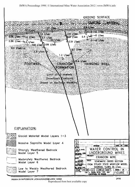
EXPLANATION:
Glacial Material Model Layers 1 -3
Massive Saprolite Model Layer 4
Strongly Weathered Bedrock Model Layer 5
Moderately Weathered Bedrock Model Layer 6
Low to Weakly Weathered Bedrock Model Layer 7
IMWA SYMPOSIUM JOHANNESBURG 1998 205
IMWA Proceedings 1998 | © International Mine Water Association 2012 | www.IMWA.info
Reproduced from best available copy

1\l
0 Ol ;: ~ Ul -< ;:
1J
0 !!! c ;:
L. 0 J:
)> z z tT
l Ul
!D c :n
G) "' "' (II
4140
QN
/l
Min
e D
rift
s
4 D
rain
ag
e
Bo
reh
ole
s ~1)-\'l.C
O· ~:
w g ,;:.
l~l
'-.P
0 •
('")
(/)
:I: .,
\&~::~ I .
tt:,~~
0·
«)'
co
lls~>'
'9c
~>'£\
DS
:U-2
0C
OR
E ZO
NE
Fa
ult
T
race
W
ith
Dip
Ore
B
ody
Cla
y A
ltere
d
"San
ded"
C
SHF
. 41
.400
N
WAT
ER
CO
NTR
OL
IN
UN
DER
GR
OU
ND
M
INES
IMWA Proceedings 1998 | © International Mine Water Association 2012 | www.IMWA.info
Reproduced from best available copy

IMWA SYMPOSIUM J URG 1998 OHANNESB -------- 207
IMWA Proceedings 1998 | © International Mine Water Association 2012 | www.IMWA.info
Reproduced from best available copy

Ill 0 (X)
~ ~ ~ 3:
"tl 0 !!! c 3:
<... 0 J:
)> z z 111
CJl
lXI c ;u
Gl - 10 10
(X)
EX
PLA
NA
TIO
N:
Gos
son
Str
on
g
Wea
ther
ing
Mod
erat
o W
eath
erin
g
Low
W
eath
erin
g
Wea
k W
eath
erin
g
w;~
Gla
cia
l M
ater
ial
Ore
B
ody
IMWA Proceedings 1998 | © International Mine Water Association 2012 | www.IMWA.info
Reproduced from best available copy

EXPLANATION:
Glacial Material Model Layers 1-3
Massive Saprolite Model Layer 4
Strongly Weathered Bedrock Model Loyer 5
Moderately Weathered Bedrock Model Loyer 6
Low to Weakly Weathered Bedrock Model Loyer 7
IMWA SYMPOSIUM JOHANNESBURG 1998 209
IMWA Proceedings 1998 | © International Mine Water Association 2012 | www.IMWA.info
Reproduced from best available copy

N
0 i ~
)> ~ " ~ !!! c " <.... 0 :t
)> z z rn m
c :XI
(;')
<!)
<!)
(l)
4140
QN
..
~.--
-oso ...
\'J!
Wfn
e D
rift
s Bor
•hol
es ~ F
oult
T
roce
W
ith
Oip
Ore
B
ody
Cla
y A
lf•r
ed
"Sor
.d•d
" C
SH
r
. ..
• J-40
0.1'1
~-''0
IMWA Proceedings 1998 | © International Mine Water Association 2012 | www.IMWA.info
Reproduced from best available copy

.·,
<< -· I + ~"' ..... (WIJ) _.__'-1
.~ ,_-*'* __ ···- -.......... ~ I
~ ... , Molor'_......,..l
~~==
211 !MWA SYMPOSIUM JOHANNESBURG 1998
IMWA Proceedings 1998 | © International Mine Water Association 2012 | www.IMWA.info
Reproduced from best available copy

"' "' 3: ~ ~ 3: , 0 !!! c 3: ... 0 :t >
z z 1"1
(/1 OJ c ~ Gl
10
10
Q)
ED
} O
oa1o
n
~
Sl-
vng
Wea
lhtlr
ii'\Q
Nod~te
Wt'I
!HII
rll"
'§
t=m
l-
Wea
ther
ing
c:::J
W1e
1k W.
athe
rir~
g
~
Gla
clci
N'a
ftri
al
r~;~
) O
r. l
ody
IMWA Proceedings 1998 | © International Mine Water Association 2012 | www.IMWA.info
Reproduced from best available copy
Recommended