2012 Washington State Energy Code CE-1
Chapter 51-11C WAC
STATE BUILDING CODE ADOPTION AND AMENDMENT OF THE 2012 EDITION OF THE
INTERNATIONAL ENERGY CONSERVATION CODE, COMMERCIAL PROVISIONS
WASHINGTON STATE ENERGY CODE, COMMERCIAL PROVISIONS
TABLE OF CONTENTS
Chapter 1 Scope and Administration ........................... CE-3
C101 Scope and General
Requirements ................................. CE-3
C102 Alternate Materials—Method of
Construction, Design or
Insulating Systems ......................... CE-8
C103 Construction Documents ................... CE-8
C104 Inspections ........................................ CE-9
C105 Validity ........................................... CE-10
C106 Referenced Standards ...................... CE-10
C107 Fees ................................................. CE-10
C108 Stop Work Order ............................. CE-11
C109 Board of Appeals ............................ CE-11
C110 Violations ........................................ CE-11
C111 Liability ........................................... CE-11
Chapter 2 Definitions ............................. CE-13
C201 General ............................................ CE-13
C202 General Definitions ......................... CE-13
Chapter 3 General Requirements .......... CE-21
C301 Climate Zones ................................. CE-21
C302 Design Conditions ........................... CE-21
C303 Materials, Systems
and Equipment ............................. CE-21
Chapter 4 Commercial Energy Efficiency .............................. CE-25
C401 General ............................................ CE-25
C402 Building Envelope Requirements .... CE-25
C403 Building Mechanical Systems ......... CE-41
C404 Service Water Heating..................... CE-74
C405 Electrical Power and
Lighting Systems ......................... CE-76
C406 Reserved
C407 Total Building Performance ............ CE-85
C408 System Commissioning ................... CE-95
C409 Energy Metering and Energy
Consumption Management .......... CE-99
Chapter 5 Referenced Standards ....... CE-102
CE-2 2012 Washington State Energy Code
Second Printing July 2013
2012 Washington State Energy Code CE-3
CHAPTER 1 [CE]
SCOPE AND ADMINISTRATION
SECTION C101 SCOPE AND GENERAL REQUIREMENTS
C101.1 Title. This code shall be known as the
International Energy Conservation Code of [NAME OF
JURISDICTION], and shall be cited as such. It is referred
to herein as "this code."
C101.2 Scope. This code applies to commercial
buildings and the buildings sites and associated systems
and equipment.
Exception: The provisions of this code do not apply to
temporary growing structures used solely for the
commercial production of horticultural plants
including ornamental plants, flowers, vegetables, and
fruits. "Temporary growing structure" means a
structure that has the sides and roof covered with
polyethylene, polyvinyl, or similar flexible synthetic
material and is used to provide plants with either frost
protection or increased heat retention. A temporary
growing structure is not considered a building for
purposes of this code.
C101.3 Intent. This code shall regulate the design and
construction of buildings for the effective use and
conservation of energy over the useful life of each
building. This code is intended to provide flexibility to
permit the use of innovative approaches and techniques
to achieve this objective. This code is not intended to
abridge safety, health or environmental requirements
contained in other applicable codes or ordinances.
C101.4 Applicability. Where, in any specific case,
different sections of this code specify different materials,
methods of construction or other requirements, the most
restrictive shall govern. Where there is a conflict
between a general requirement and a specific
requirement, the specific requirement shall govern.
C101.4.1 Existing buildings. Except as specified in
this chapter, this code shall not be used to require the
removal, alteration or abandonment of, nor prevent the
continued use and maintenance of, an existing building
or building system lawfully in existence at the time of
adoption of this code.
C101.4.2 Historic buildings. The building official
may modify the specific requirements of this code for
historic buildings and require in lieu of alternate
requirements which will result in a reasonable degree
of energy efficiency. This modification may be
allowed for those buildings or structures that are listed
in the state or national register of historic places;
designated as a historic property under local or state
designation law or survey; certified as a contributing
resource with a national register listed or locally
designated historic district; or with an opinion or
certification that the property is eligible to be listed on
the national or state registers of historic places either
individually or as a contributing building to a historic
district by the state historic preservation officer or the
keeper of the national register of historic places.
C101.4.3 Additions, alterations, renovations or
repairs. Additions, alterations, renovations or repairs
to an existing building, building system or portion
thereof shall conform to the provisions of this code as
they relate to new construction without requiring the
unaltered portion(s) of the existing building or building
system to comply with this code. Additions,
alterations, renovations or repairs shall not create an
unsafe or hazardous condition or overload existing
building systems. An addition shall be deemed to
comply with this code if the addition alone complies or
if the existing building and addition comply with this
code as a single building.
Exception: The following need not comply
provided the energy use of the building is not
increased:
1. Storm windows installed over existing
fenestration.
2. Glass only replacements in an existing sash
and frame.
3. Existing ceiling, wall or floor cavities
exposed during construction provided that
these cavities are insulated to full depth with
insulation having a minimum nominal value
of R-3.0 per inch installed per Section C402.
4. Construction where the existing roof, wall or
floor cavity is not exposed.
CE-4 2012 Washington State Energy Code
5. Reroofing for roofs where neither the
sheathing nor the insulation is exposed. Roofs
without insulation in the cavity and where the
sheathing or insulation is exposed during
reroofing shall be insulated either above or
below the sheathing.
6. Replacement of existing doors that separate
conditioned space from the exterior shall not
require the installation of a vestibule or
revolving door, provided, however, that an
existing vestibule that separates a conditioned
space from the exterior shall not be removed.
7. Alterations to lighting systems only that
replace less than 60 percent of the luminaires
in a space, provided that such alterations do
not increase the installed interior lighting
power.
8. Alterations that replace only the bulb and
ballast within the existing luminaires in a
space provided that the alteration does not
increase the installed interior lighting power.
C101.4.3.1 Lighting and motors. Alterations that
replace 60 percent or more of the luminaires in a
space enclosed by walls or ceiling-height partitions
shall comply with Sections C405.5 and C405.6.
Where less than 60 percent of the fixtures in a space
enclosed by walls or ceiling-height partitions are
new, the installed lighting wattage shall be
maintained or reduced.
Where new wiring is being installed to serve
added fixtures and/or fixtures are being relocated to
a new circuit, controls shall comply with Sections
C405.2.1, C405.2.2.3, C405.2.3, C405.3.4, and as
applicable C408.3. In addition, office areas less than
300 ft2 enclosed by walls or ceiling-height partitions,
and all meeting and conference rooms, and all
school classrooms, shall be equipped with
occupancy sensors that comply with Section
C405.2.2 and C408.3. Where a new lighting panel
(or a moved lighting panel) with all new raceway
and conductor wiring from the panel to the fixtures
is being installed, controls shall also comply with
the other requirements in Sections C405.2.2 and
C408.3.
Where new walls or ceiling-height partitions are
added to an existing space and create a new enclosed
space, but the lighting fixtures are not being
changed, other than being relocated, the new
enclosed space shall have controls that comply with
Sections C405.2.1, C 405.2.2, C405.2.3 and C408.3.
Those motors which are altered or replaced shall
comply with Section C403.2.13.
C101.4.3.2 Mechanical systems. Those parts of
systems which are altered or replaced shall comply
with Section C403. Additions or alterations shall not
be made to an existing mechanical system that will
cause the existing mechanical system to become out
of compliance.
All new systems in existing buildings, including
packaged unitary equipment and packaged split
systems, shall comply with Section C403.
Where mechanical cooling is added to a space
that was not previously cooled, the mechanical
cooling system shall comply with the economizer
requirements in Section C403.3.1 or C403.4.1.
Exception: Alternate designs that are not in full
compliance with this code may be approved when
the building official determines that existing
building or occupancy constraints make full
compliance impractical or where full compliance
would be economically impractical.
Alterations to existing mechanical cooling
systems shall not decrease economizer capacity
unless the system complies with Section C403.3.1 or
C403.4.1. In addition, for existing mechanical
cooling systems that do not comply with Sections
C403.3.1 or Section 403.4.1, including both the
individual unit size limits and the total building
capacity limits on units without economizer, other
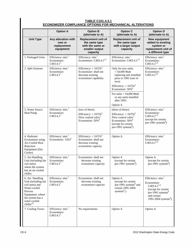
alterations shall comply with Table C101.4.3.1.
When space cooling equipment is replaced,
controls shall be installed to provide for integrated
operation with economizer in accordance with
Section C403.3.
Existing equipment currently in use may be
relocated within the same floor or same tenant space
if removed and reinstalled within the same permit.
C101.4.4 Change in occupancy or use. Spaces
undergoing a change in occupancy from an F, S or U
occupancy to an occupancy other than F, S or U shall
comply with this code. Any space that is converted to a
residential dwelling unit or portion thereof, from
another use or occupancy shall comply with this code.
Where the use in a space changes from one use in
Table C405.5.2(1) or (2) to another use in Table
C405.5.2(1) or (2), the installed lighting wattage shall
comply with Section C405.5.
Exception: Where the component performance
building envelope option in Section C402.1.3 is used
to comply with this section, the Proposed UA is
allowed to be up to 110 percent of the Target UA.
Where the total building performance option in
Section C407 is used to comply with this section, the
2012 Washington State Energy Code CE-5
annual energy consumption of the proposed design
is allowed to be 110 percent of the annual energy
consumption otherwise allowed by Section C407.3
and Section C401.2 (3).
C101.4.5 Change in space conditioning. Any
nonconditioned space that is altered to become
conditioned space or semi-heated space shall be
required to be brought into full compliance with this
code. Any semi-heated space that is altered to become
conditioned space shall be required to be brought into
full compliance with this code.
Exception: Where the component performance
building envelope option in Section C402.1.3 is used
to comply with this section, the Proposed UA is
allowed to be up to 110 percent of the Target UA.
Where the total building performance option in
Section C407 is used to comply with this section, the
annual energy consumption of the proposed design
is allowed to be 110 percent of the annual energy
consumption otherwise allowed by Section C407.3
and Section C401.2 (3).
C101.4.6 Mixed occupancy. Where a building
includes both residential and commercial occupancies,
each occupancy shall be separately considered and
meet the applicable provisions of IECC--Commercial
Provisions or IECC--Residential Provisions.
C101.5 Compliance. Residential buildings shall meet
the provisions of IECC--Residential Provisions.
Commercial buildings shall meet the provisions of
IECC--Commercial Provisions.
C101.5.1 Compliance materials. The code official
shall be permitted to approve specific computer
software, worksheets, compliance manuals and other
similar materials that meet the intent of this code.
C101.5.2 Low energy buildings. The following
buildings, or portions thereof, separated from the
remainder of the building by building thermal
envelope assemblies complying with this code shall be
exempt from all thermal envelope provisions of this
code:
1. Those that are heated and/or cooled with a peak
design rate of energy usage less than 3.4 Btu/h 2 (10.7 W/m
2) or 1.0 watt/ft
2 (10.7 W/m
2) of
floor area for space conditioning purposes.
2. Those that do not contain conditioned space.
3. Greenhouses isolated from any conditioned
space and not intended for occupancy.
C101.5.2.1 Semi-heated spaces. A semi-heated
space shall meet all of the building thermal envelope
requirements, except that insulation is not required
for opaque wall assemblies. Component
performance calculations involving semi-heated
spaces shall calculate fully insulated opaque walls
for the Target UA calculation, and Total Building
Performance calculations involving semi-heated
spaces shall calculate fully insulated opaque walls
for the Standard Reference Design.
SECTION C102 ALTERNATE MATERIALS-METHOD
OF CONSTRUCTION, DESIGN OR INSULATING SYSTEMS
C102.1 General. This code is not intended to prevent the
use of any material, method of construction, design or
insulating system not specifically prescribed herein,
provided that such construction, design or insulating
system has been approved by the code official as meeting
the intent of this code.
SECTION C103 CONSTRUCTION DOCUMENTS
C103.1 General. Construction documents and other
supporting data shall be submitted in one or more sets
with each application for a permit. The construction
documents shall be prepared by a registered design
professional where required by the statutes of the
jurisdiction in which the project is to be constructed.
Where special conditions exist, the code official is
authorized to require necessary construction documents
to be prepared by a registered design professional.
Exception: The code official is authorized to waive
the requirements for construction documents or other
supporting data if the code official determines they are
not necessary to confirm compliance with this code.
C103.2 Information on construction documents.
Construction documents shall be drawn to scale upon
suitable material. Electronic media documents are
permitted to be submitted when approved by the code
official. Construction documents shall be of sufficient
clarity to indicate the location, nature and extent of the
work proposed, and show in sufficient detail pertinent
data and features of the building, systems and equipment
as herein governed. Details shall include, but are not
limited to, as applicable, insulation materials and their
R-values; fenestration U-factors and SHGCs;
area-weighted U-factor and SHGC calculations;
mechanical system design criteria; mechanical and
service water heating system and equipment types, sizes
and efficiencies; economizer description; equipment and
systems controls; fan motor horsepower (hp) and
controls; duct sealing, duct and pipe insulation and
location; lighting fixture schedule with wattage and
control narrative; and air sealing details.
CE-6 2012 Washington State Energy Code
TABLE C101.4.3.1 ECONOMIZER COMPLIANCE OPTIONS FOR MECHANICAL ALTERATIONS
Option A Option B (alternate to A)
Option C (alternate to A)
Option D (alternate to A)
Unit Type Any alteration with new or
replacement equipment
Replacement unit of the same type
with the same or smaller output
capacity
Replacement unit of the same type
with a larger output capacity
New equipment added to existing
system or replacement unit of
a different type
1. Packaged Units Efficiency: min.1
Economizer: C403.4.12
Efficiency: min.1
Economizer: C403.4.12,3
Efficiency: min.1
Economizer: C403.4.12,3
Efficiency: min.1
Economizer: C403.4.12,4
2. Split Systems Efficiency: min.1
Economizer: C403.4.12
Efficiency: + 10/5%5
Economizer: shall not
decrease existing economizer capability
Only for new units
< 54,000 Btuh
replacing unit installed
prior to 1991 (one of
two):
Efficiency: + 10/5%5
Economizer: 50%6
Efficiency: min.1
Economizer: C403.4.12,4
For units > 54,000 Btuh
or any units installed
after 1991:
Option A
3. Water Source
Heat Pump
Efficiency: min.1
Economizer: C403.4.12
(two of three):
Efficiency: + 10/5%5
Flow control valve7 Economizer: 50%6
(three of three):
Efficiency: + 10/5%5
Flow control valve7
Economizer: 50%6
(except for certain pre-1991 systems8)
Efficiency: min.1
Economizer:
C403.4.12,4
(except for certain pre-1991 systems8)
4. Hydronic
Economizer using
Air-Cooled Heat
Rejection
Equipment (Dry Cooler)
Efficiency: min.1
Economizer: 14332
Efficiency: + 10/5%5
Economizer: shall not
decrease existing
economizer capacity
Option A Efficiency: min.1
Economizer: C403.4.12,4
5. Air-Handling
Unit (including fan
coil units)
where the system
has an air-cooled chiller
Efficiency: min.1
Economizer: C403.4.12
Economizer: shall not
decrease existing economizer capacity
Option A
(except for certain pre-1991 systems8)
Option A
(except for certain pre-1991 systems8)
6. Air- Handling
Unit (including fan
coil units) and
Water-cooled
Process
Equipment, where
the system has a
water-cooled
chiller10
Efficiency: min.1
Economizer:
C403.4.12
Economizer: shall not
decrease existing
economizer capacity
Option A
(except for certain
pre-1991 systems8 and
certain 1991-2004
systems9.)
Efficiency: min.1
Economizer:
C403.4.12,4
(except for certain
pre-1991 systems8
and certain 1991-2004 systems9)
7. Cooling Tower Efficiency: min.1
Economizer: C403.4.12
No requirements Option A Option A
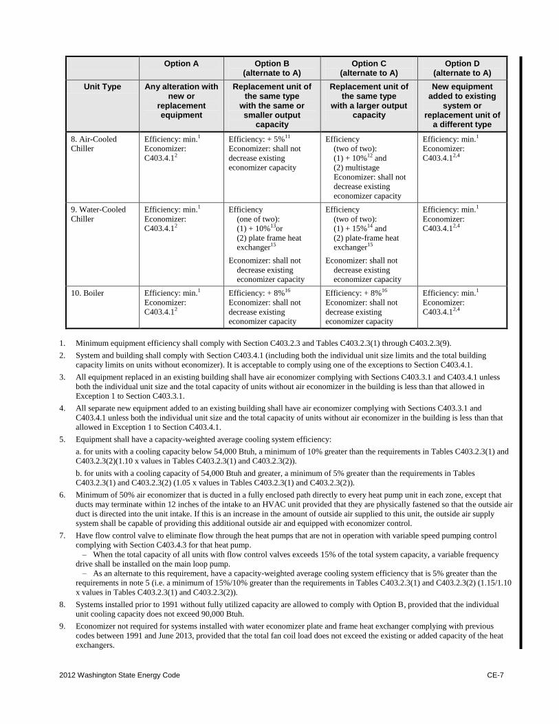
2012 Washington State Energy Code CE-7
Option A Option B (alternate to A)
Option C (alternate to A)
Option D (alternate to A)
Unit Type Any alteration with new or
replacement equipment
Replacement unit of the same type
with the same or smaller output
capacity
Replacement unit of the same type
with a larger output capacity
New equipment added to existing
system or replacement unit of
a different type
8. Air-Cooled Chiller
Efficiency: min.1
Economizer:
C403.4.12
Efficiency: + 5%11
Economizer: shall not
decrease existing economizer capacity
Efficiency
(two of two):
(1) + 10%12 and
(2) multistage
Economizer: shall not
decrease existing
economizer capacity
Efficiency: min.1
Economizer:
C403.4.12,4
9. Water-Cooled
Chiller
Efficiency: min.1
Economizer:
C403.4.12
Efficiency
(one of two):
(1) + 10%13or
(2) plate frame heat exchanger15
Economizer: shall not
decrease existing economizer capacity
Efficiency
(two of two):
(1) + 15%14 and
(2) plate-frame heat exchanger15
Economizer: shall not
decrease existing economizer capacity
Efficiency: min.1
Economizer:
C403.4.12,4
10. Boiler Efficiency: min.1
Economizer:
C403.4.12
Efficiency: + 8%16
Economizer: shall not
decrease existing economizer capacity
Efficiency: + 8%16
Economizer: shall not
decrease existing economizer capacity
Efficiency: min.1
Economizer:
C403.4.12,4
1. Minimum equipment efficiency shall comply with Section C403.2.3 and Tables C403.2.3(1) through C403.2.3(9).
2. System and building shall comply with Section C403.4.1 (including both the individual unit size limits and the total building
capacity limits on units without economizer). It is acceptable to comply using one of the exceptions to Section C403.4.1.
3. All equipment replaced in an existing building shall have air economizer complying with Sections C403.3.1 and C403.4.1 unless
both the individual unit size and the total capacity of units without air economizer in the building is less than that allowed in
Exception 1 to Section C403.3.1.
4. All separate new equipment added to an existing building shall have air economizer complying with Sections C403.3.1 and
C403.4.1 unless both the individual unit size and the total capacity of units without air economizer in the building is less than that
allowed in Exception 1 to Section C403.4.1.
5. Equipment shall have a capacity-weighted average cooling system efficiency:
a. for units with a cooling capacity below 54,000 Btuh, a minimum of 10% greater than the requirements in Tables C403.2.3(1) and
C403.2.3(2)(1.10 x values in Tables C403.2.3(1) and C403.2.3(2)).
b. for units with a cooling capacity of 54,000 Btuh and greater, a minimum of 5% greater than the requirements in Tables
C403.2.3(1) and C403.2.3(2) (1.05 x values in Tables C403.2.3(1) and C403.2.3(2)).
6. Minimum of 50% air economizer that is ducted in a fully enclosed path directly to every heat pump unit in each zone, except that
ducts may terminate within 12 inches of the intake to an HVAC unit provided that they are physically fastened so that the outside air
duct is directed into the unit intake. If this is an increase in the amount of outside air supplied to this unit, the outside air supply
system shall be capable of providing this additional outside air and equipped with economizer control.
7. Have flow control valve to eliminate flow through the heat pumps that are not in operation with variable speed pumping control
complying with Section C403.4.3 for that heat pump.
– When the total capacity of all units with flow control valves exceeds 15% of the total system capacity, a variable frequency
drive shall be installed on the main loop pump.
– As an alternate to this requirement, have a capacity-weighted average cooling system efficiency that is 5% greater than the
requirements in note 5 (i.e. a minimum of 15%/10% greater than the requirements in Tables C403.2.3(1) and C403.2.3(2) (1.15/1.10
x values in Tables C403.2.3(1) and C403.2.3(2)).
8. Systems installed prior to 1991 without fully utilized capacity are allowed to comply with Option B, provided that the individual
unit cooling capacity does not exceed 90,000 Btuh.
9. Economizer not required for systems installed with water economizer plate and frame heat exchanger complying with previous
codes between 1991 and June 2013, provided that the total fan coil load does not exceed the existing or added capacity of the heat
exchangers.
CE-8 2012 Washington State Energy Code
10. For water-cooled process equipment where the manufacturers specifications require colder temperatures than available with
waterside economizer, that portion of the load is exempt from the economizer requirements.
11. The air-cooled chiller shall have an IPLV efficiency that is a minimum of 5% greater than the IPLV requirements in Table
C403.2.3(7)(1.05 x IPLV values in Table C403.2.3(7)).
12. The air-cooled chiller shall:
a. have an IPLV efficiency that is a minimum of 10% greater than the IPLV requirements in Table C403.2.3(7) (1.10 x IPLV values
in Table C403.2.3(7)), and
b. be multistage with a minimum of two compressors.
13. The water-cooled chiller shall have an IPLV efficiency that is a minimum of 10% greater than the IPLV requirements in Table
C403.2.3(7) (1.10 x IPLV values in Table C403.2.3(7)).
14. The water-cooled chiller shall have an IPLV efficiency that is a minimum of 15% greater than the IPLV requirements in Table
C403.2.3(7), (1.15 x IPLV values in Table C403.2.3(7)).
15. Economizer cooling shall be provided by adding a plate-frame heat exchanger on the waterside with a capacity that is a minimum of
20% of the chiller capacity at standard AHRI rating conditions.
16. The replacement boiler shall have an efficiency that is a minimum of 8% higher than the value in Table C403.2.3(5) (1.08 x value in
Table C403.2.3(5)), except for electric boilers.
C103.3 Examination of documents. The code official
shall examine or cause to be examined the accompanying
construction documents and shall ascertain whether the
construction indicated and described is in accordance
with the requirements of this code and other pertinent
laws or ordinances.
C103.3.1 Approval of construction documents.
When the code official issues a permit where
construction documents are required, the construction
documents shall be endorsed in writing and stamped
"Reviewed for Code Compliance." Such approved
construction documents shall not be changed, modified
or altered without authorization from the code official.
Work shall be done in accordance with the approved
construction documents.
One set of construction documents so reviewed
shall be retained by the code official. The other set
shall be returned to the applicant, kept at the site of
work and shall be open to inspection by the code
official or a duly authorized representative.
C103.3.2 Previous approvals. This code shall not
require changes in the construction documents,
construction or designated occupancy of a structure for
which a lawful permit has been heretofore issued or
otherwise lawfully authorized, and the construction of
which has been pursued in good faith within 180 days
after the effective date of this code and has not been
abandoned.
C103.3.3 Phased approval. The code official shall
have the authority to issue a permit for the construction
of part of an energy conservation system before the
construction documents for the entire system have
been submitted or approved, provided adequate
information and detailed statements have been filed
complying with all pertinent requirements of this code.
The holders of such permit shall proceed at their own
risk without assurance that the permit for the entire
energy conservation system will be granted.
C103.4 Amended construction documents. Changes
made during construction that are not in compliance with
the approved construction documents shall be
resubmitted for approval as an amended set of
construction documents.
C103.5 Retention of construction documents. One set
of approved construction documents shall be retained by
the code official for a period of not less than 180 days
from date of completion of the permitted work, or as
required by state or local laws.
SECTION C104 INSPECTIONS
C104.1 General. Construction or work for which a
permit is required shall be subject to inspection by the
code official.
C104.2 Required approvals. Work shall not be done
beyond the point indicated in each successive inspection
without first obtaining the approval of the code official.
The code official, upon notification, shall make the
requested inspections and shall either indicate the portion
of the construction that is satisfactory as completed, or
notify the permit holder or his or her agent wherein the
same fails to comply with this code. Any portions that do
not comply shall be corrected and such portion shall not
be covered or concealed until authorized by the code
official. Where applicable, inspections shall include at
least:
2012 Washington State Energy Code CE-9
C104.2.1 Envelope
C104.2.1.1 Wall Insulation Inspection: To be made
after all wall insulation and air vapor retarder sheet
or film materials are in place, but before any wall
covering is placed.
C104.2.1.2 Glazing Inspection: To be made after
glazing materials are installed in the building.
C104.2.1.3 Exterior Roofing Insulation: To be
made after the installation of the roof insulation, but
before concealment.
C104.2.1.4 Slab/Floor Insulation: To be made after
the installation of the slab/floor insulation, but
before concealment.
C104.2.2 Mechanical
C104.2.2.1 Mechanical Equipment Efficiency and
Economizer: To be made after all equipment and
controls required by this code are installed and prior
to the concealment of such equipment or controls.
C104.2.2.2 Mechanical Pipe and Duct Insulation:
To be made after all pipe and duct insulation is in
place, but before concealment.
C104.2.3 Lighting and motors
C104.2.3.1 Lighting Equipment and Controls: To
be made after the installation of all lighting
equipment and controls required by this code, but
before concealment of the lighting equipment.
C104.2.3.2 Motor Inspections: To be made after
installation of all equipment covered by this code,
but before concealment.
C104.3 Final inspection. The building shall have a final
inspection and not be occupied until approved.
C104.4 Reinspection. A building shall be reinspected
when determined necessary by the code official.
C104.5 Approved inspection agencies. The code
official is authorized to accept reports of approved
inspection agencies, provided such agencies satisfy the
requirements as to qualifications and reliability.
C104.6 Inspection requests. It shall be the duty of the
holder of the permit or their duly authorized agent to
notify the code official when work is ready for
inspection. It shall be the duty of the permit holder to
provide access to and means for inspections of such work
that are required by this code.
C104.7 Reinspection and testing. Where any work or
installation does not pass an initial test or inspection, the
necessary corrections shall be made so as to achieve
compliance with this code. The work or installation shall
then be resubmitted to the code official for inspection
and testing.
C104.8 Approval. After the prescribed tests and
inspections indicate that the work complies in all
respects with this code, a notice of approval shall be
issued by the code official.
C104.8.1 Revocation. The code official is authorized
to, in writing, suspend or revoke a notice of approval
issued under the provisions of this code wherever the
certificate is issued in error, or on the basis of incorrect
information supplied, or where it is determined that the
building or structure, premise, or portion thereof is in
violation of any ordinance or regulation or any of the
provisions of this code.
SECTION C105
VALIDITY
C105.1 General. If a portion of this code is held to be
illegal or void, such a decision shall not affect the
validity of the remainder of this code.
SECTION C106
REFERENCED STANDARDS
C106.1 Referenced codes and standards. The codes
and standards referenced in this code shall be those listed
in Chapter 5, and such codes and standards shall be
considered as part of the requirements of this code to the
prescribed extent of each such reference and as further
regulated in Sections C106.1.1 and C106.1.2.
C106.1.1 Conflicts. Where differences occur between
provisions of this code and referenced codes and
standards, the provisions of this code shall apply.
C106.1.2 Provisions in referenced codes and
standards. Where the extent of the reference to a
referenced code or standard includes subject matter
that is within the scope of this code, the provisions of
this code, as applicable, shall take precedence over the
provisions in the referenced code or standard.
C106.2 Conflicting requirements. Where the provisions
of this code and the referenced standards conflict, the
provisions of this code shall take precedence.
C106.3 Application of references. References to
chapter or section numbers, or to provisions not
specifically identified by number, shall be construed to
refer to such chapter, section or provision of this code.
C106.4 Other laws. The provisions of this code shall not
be deemed to nullify any provisions of local, state or
federal law. In addition to the requirements of this code,
all occupancies shall conform to the provisions included
in the State Building Code (chapter 19.27 RCW). In case
of conflicts among the codes enumerated in RCW
19.27.031 (1) through (4) and this code, an earlier named
CE-10 2012 Washington State Energy Code
code shall govern over those following. In the case of
conflict between the duct sealing and insulation
requirements of this code and the duct insulation
requirements of Sections 603 and 604 of the
International Mechanical Code, the duct insulation
requirements of this code, or where applicable, a local
jurisdiction's energy code shall govern.
SECTION C107 FEES
C107.1 Fees. A permit shall not be issued until the fees
prescribed in Section C107.2 have been paid, nor shall an
amendment to a permit be released until the additional
fee, if any, has been paid.
C107.2 Schedule of permit fees. A fee for each permit
shall be paid as required, in accordance with the schedule
as established by the applicable governing authority.
C107.3 Work commencing before permit issuance.
Any person who commences any work before obtaining
the necessary permits shall be subject to an additional fee
established by the code official, which shall be in
addition to the required permit fees.
C107.4 Related fees. The payment of the fee for the
construction, alteration, removal or demolition of work
done in connection to or concurrently with the work or
activity authorized by a permit shall not relieve the
applicant or holder of the permit from the payment of
other fees that are prescribed by law.
C107.5 Refunds. The code official is authorized to
establish a refund policy.
SECTION C108 STOP WORK ORDER
C108.1 Authority. Whenever the code official finds any
work regulated by this code being performed in a manner
either contrary to the provisions of this code or
dangerous or unsafe, the code official is authorized to
issue a stop work order.
C108.2 Issuance. The stop work order shall be in writing
and shall be given to the owner of the property involved,
or to the owner's agent, or to the person doing the work.
Upon issuance of a stop work order, the cited work shall
immediately cease. The stop work order shall state the
reason for the order, and the conditions under which the
cited work will be permitted to resume.
C108.3 Emergencies. Where an emergency exists, the
code official shall not be required to give a written notice
prior to stopping the work.
C108.4 Failure to comply. Any person who shall
continue any work after having been served with a stop
work order, except such work as that person is directed
to perform to remove a violation or unsafe condition,
shall be liable to a fine of not less than [AMOUNT] dollars
or more than [AMOUNT] dollars.
SECTION C109 BOARD OF APPEALS
C109.1 General. In order to hear and decide appeals of
orders, decisions or determinations made by the code
official relative to the application and interpretation of
this code, there shall be and is hereby created a board of
appeals. The code official shall be an ex officio member
of said board but shall have no vote on any matter before
the board. The board of appeals shall be appointed by the
governing body and shall hold office at its pleasure. The
board shall adopt rules of procedure for conducting its
business, and shall render all decisions and findings in
writing to the appellant with a duplicate copy to the code
official.
C109.2 Limitations on authority. An application for
appeal shall be based on a claim that the true intent of
this code or the rules legally adopted thereunder have
been incorrectly interpreted, the provisions of this code
do not fully apply or an equally good or better form of
construction is proposed. The board shall have no
authority to waive requirements of this code.
C109.3 Qualifications. The board of appeals shall
consist of members who are qualified by experience and
training and are not employees of the jurisdiction.
SECTION C110 VIOLATIONS
It shall be unlawful for any person, firm, or corporation
to erect or construct any building, or remodel or
rehabilitate any existing building or structure in the state,
or allow the same to be done, contrary to or in violation
of any of the provisions of this code.
SECTION C111 LIABILITY
Nothing contained in this code is intended to be nor shall
be construed to create or form the basis for any liability
on the part of any city or county or its officers,
employees or agents for any injury or damage resulting
from the failure of a building to conform to the
provisions of this code.
2012 Washington State Energy Code CE-11
CHAPTER 2 [CE]
DEFINITIONS
SECTION C201 GENERAL
C201.1 Scope. Unless stated otherwise, the following
words and terms in this code shall have the meanings
indicated in this chapter.
C201.2 Interchangeability. Words used in the present
tense include the future; words in the masculine gender
include the feminine and neuter; the singular number
includes the plural and the plural includes the singular.
C201.3 Terms defined in other codes. Terms that are
not defined in this code but are defined in the
International Building Code, International Fire Code,
International Fuel Gas Code, International Mechanical
Code, Uniform Plumbing Code or the International
Residential Code shall have the meanings ascribed to
them in those codes.
C201.4 Terms not defined. Terms not defined by this
chapter shall have ordinarily accepted meanings such as
the context implies.
SECTION C202 GENERAL DEFINITIONS
ABOVE-GRADE WALL. A wall enclosing conditioned
space that is not a below-grade wall. This includes
between-floor spandrels, peripheral edges of floors, roof
and basement knee walls, dormer walls, gable end walls,
walls enclosing a mansard roof and skylight shafts.
ACCESSIBLE. Admitting close approach as a result of not
being guarded by locked doors, elevation or other
effective means (see "Readily accessible").
ADDITION. An extension or increase in the conditioned
space floor area or height of a building or structure.
AIR BARRIER. Material(s) assembled and joined together
to provide a barrier to air leakage through the building
envelope. An air barrier may be a single material or a
combination of materials.
ALTERATION. Any construction or renovation to an
existing structure other than repair or addition that
requires a permit. Also, a change in a mechanical system
that involves an extension, addition or change
to the arrangement, type or purpose of the original
installation that requires a permit.
APPROVED. Approval by the code official as a result of
investigation and tests conducted by him or her, or by
reason of accepted principles or tests by nationally
recognized organizations.
ATTIC AND OTHER ROOFS. All other roofs, including
roofs with insulation entirely below (inside of) the roof
structure (i.e., attics, cathedral ceilings, and single-rafter
ceilings), roofs with insulation both above and below the
roof structure, and roofs without insulation but excluding
roofs with insulation entirely above deck and metal
building roofs.
AUTOMATIC. Self-acting, operating by its own
mechanism when actuated by some impersonal
influence, as, for example, a change in current strength,
pressure, temperature or mechanical configuration (see
"Manual").
BELOW-GRADE WALL. That portion of a wall in the
building envelope that is entirely below the finish grade
and in contact with the ground.
BUILDING. Any structure used or intended for supporting
or sheltering any use or occupancy, including any
mechanical systems, service water heating systems and
electric power and lighting systems located on the
building site and supporting the building.
BUILDING COMMISSIONING. A process that verifies and
documents that the selected building systems have been
designed, installed, and function according to the owner's
project requirements and construction documents, and to
minimum code requirements.
BUILDING ENTRANCE. Any door, set of doors, doorway,
or other form of portal that is used to gain access to the
building from the outside by the public.
BUILDING SITE. A contiguous area of land that is under
the ownership or control of one entity.
BUILDING THERMAL ENVELOPE. The below-grade walls,
above-grade walls, floor, roof, and any other building
elements that enclose conditioned space or provides a
boundary between conditioned space, semiheated space
and exempt or unconditioned space.
CE-12 2012 Washington State Energy Code
C-FACTOR (THERMAL CONDUCTANCE). The coefficient
of heat transmission (surface to surface) through a
building component or assembly, equal to the time rate
of heat flow per unit area and the unit temperature
difference between the warm side and cold side surfaces
(Btu/h ft2 x °F) [W/(m
2 x K)].
CODE OFFICIAL. The officer or other designated
authority charged with the administration and
enforcement of this code, or a duly authorized
representative.
COEFFICIENT OF PERFORMANCE (COP) - COOLING. The
ratio of the rate of heat removal to the rate of energy
input, in consistent units, for a complete refrigerating
system or some specific portion of that system under
designated operating conditions.
COEFFICIENT OF PERFORMANCE (COP) - HEATING. The
ratio of the rate of heat removal to the rate of heat
delivered to the rate of energy input, in consistent units,
for a complete heat pump system, including the
compressor and, if applicable, auxiliary heat, under
designated operating conditions.
COMMERCIAL BUILDING. For this code, all buildings that
are not included in the definition of "Residential
buildings."
CONDITIONED FLOOR AREA. The horizontal projection of
the floors associated with the conditioned space.
CONDITIONED SPACE. An area or room within a building
being heated or cooled, containing uninsulated ducts, or
with a fixed opening directly into an adjacent
conditioned space.
CONTINUOUS AIR BARRIER. A combination of materials
and assemblies that restrict or prevent the passage of air
through the building thermal envelope.
CONTINUOUS INSULATION(CI). Insulation that is
continuous across all structural members without thermal
bridges other than service openings and penetrations by
metal fasteners with a cross-sectional area, as measured
in the plane of the surface, of less than 0.04% of the
opaque surface area of the assembly. It is installed on the
interior or exterior or is integral to any opaque surface of
the building envelope.
CURTAIN WALL. Fenestration products used to create an
external nonload-bearing wall that is designed to separate
the exterior and interior environments.
DATA ACQUISITION SYSTEM. An electronic system
managed by the building owner to collect, tabulate and
display metering information.
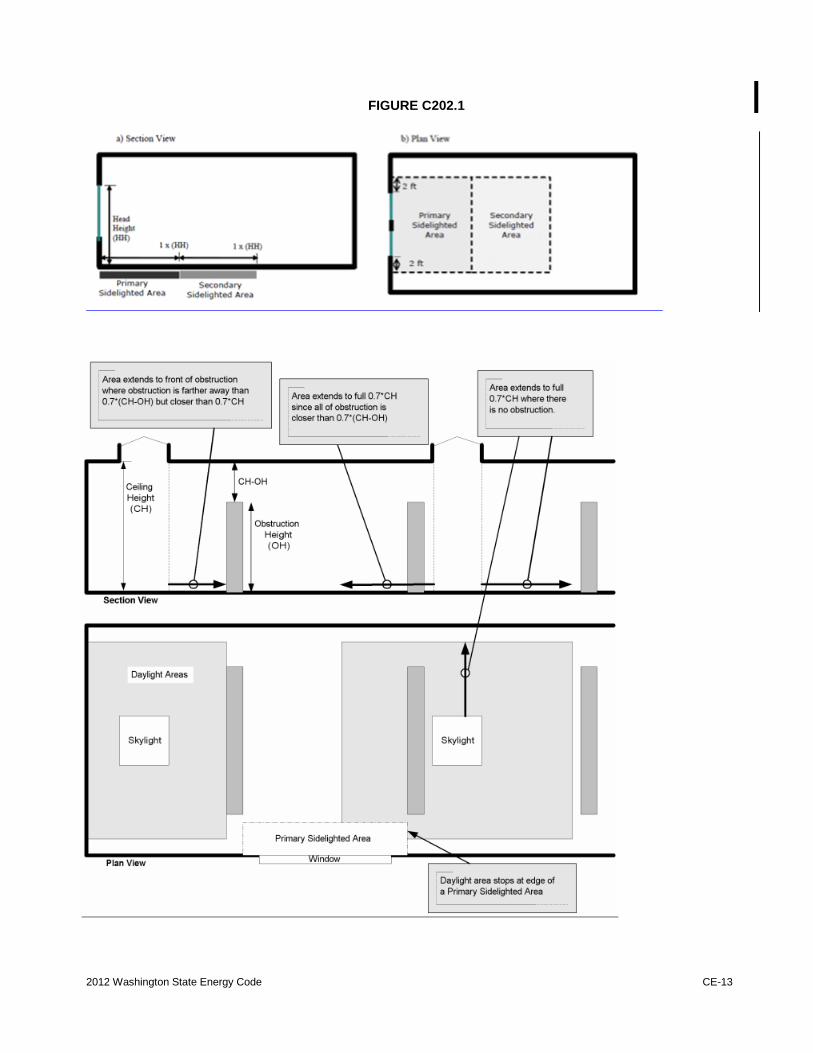
DAYLIGHT ZONE. (See also Fig. C202.4)
1. Under skylights. The area under skylights whose
horizontal dimension, in each direction, is equal to
the skylight dimension in that direction plus either
70 percent of the floor-to-ceiling height or the
dimension to a ceiling height opaque partition, or
one-half the distance to adjacent skylights or
vertical fenestration, whichever is least.
2. Adjacent to vertical fenestration. The area
adjacent to vertical fenestration which receives
daylight through the fenestration. For purposes of
this definition and unless more detailed analysis is
provided, the primary daylight zone depth is
assumed to extend into the space a distance equal
to the window head height and the secondary
daylighted zone extends from the edge of the
primary zone to a distance equal to two times the
window head height or to the nearest ceiling
height opaque partition, whichever is less. The
daylight zone width is assumed to be the width of
the window plus 2 feet (610 mm) on each side, or
the window width plus the distance to an opaque
partition, or the window width plus one-half the
distance to adjacent skylight or vertical
fenestration, whichever is least.
3. In parking garages. The area within 20 feet of
any portion of a perimeter wall that has a net
opening to wall ratio of at least 40 percent and no
exterior obstructions within 20 feet.
4. Under atrium glazing. The area at the floor
directly beneath the atrium and the top floor under
the atrium whose horizontal dimension, in each
direction, is equal to the distance between the
floor and ceiling height. Levels below the top
floor that are not directly beneath the atrium are
unaffected.
2012 Washington State Energy Code CE-13
FIGURE C202.1
CE-14 2012 Washington State Energy Code
DEMAND CONTROL VENTILATION (DCV). A ventilation
system capability that provides for the automatic
reduction of outdoor air intake below design rates when
the actual occupancy of spaces served by the system is
less than design occupancy.
DEMAND RECIRCULATION WATER SYSTEM. A water
distribution system where pump(s) prime the service hot
water piping with heated water upon demand for hot
water.
DUCT. A tube or conduit utilized for conveying air. The
air passages of self-contained systems are not to be
construed as air ducts.
DUCT SYSTEM. A continuous passageway for the
transmission of air that, in addition to ducts, includes
duct fittings, dampers, plenums, fans and accessory
air-handling equipment and appliances.
DWELLING UNIT. A single unit providing complete
independent living facilities for one or more persons,
including permanent provisions for living, sleeping,
eating, cooking and sanitation.
DYNAMIC GLAZING. Any fenestration product that has
the fully reversible ability to change its performance
properties, including U-factor, SHGC, or VT.
ECONOMIZER, AIR. A duct and damper arrangement and
automatic control system that allows a cooling system to
supply outside air to reduce or eliminate the need for
mechanical cooling during mild or cold weather.
ECONOMIZER, WATER. A system where the supply air of
a cooling system is cooled indirectly with water that is
itself cooled by heat or mass transfer to the environment
without the use of mechanical cooling.
ENCLOSED SPACE. A volume surrounded by solid
surfaces such as walls, floors, roofs, and openable
devices such as doors and operable windows.
END USE CATEGORY. A load or group of loads that
consume energy in a common or similar manner.
ENERGY ANALYSIS. A method for estimating the annual
energy use of the proposed design and standard
reference design based on estimates of energy use.
ENERGY COST. The total estimated annual cost for
purchased energy for the building functions regulated by
this code, including applicable demand charges.
ENERGY RECOVERY VENTILATION SYSTEM. Systems
that employ air-to-air heat exchangers to recover energy
from exhaust air for the purpose of
preheating, precooling, humidifying or dehumidifying
outdoor ventilation air prior to supplying the air to a
space, either directly or as part of an HVAC system.
ENERGY SIMULATION TOOL. An approved software
program or calculation-based methodology that projects
the annual energy use of a building.
ENERGY SOURCE METER. A meter placed at the source of
the incoming energy that measures the energy delivered
to the whole building or metered space.
ENTRANCE DOOR. Fenestration products used for ingress,
egress and access in nonresidential buildings including,
but not limited to, exterior entrances that utilize latching
hardware and automatic closers and contain over 50
percent glass specifically designed to withstand heavy
use and possibly abuse.
EQUIPMENT ROOM. A space that contains either
electrical equipment, mechanical equipment, machinery,
water pumps or hydraulic pumps that are a function of
the building's services.
EXTERIOR WALL. Walls including both above-grade
walls and below-grade walls.
FAN BRAKE HORSEPOWER (BHP). The horsepower
delivered to the fan's shaft. Brake horsepower does not
include the mechanical drive losses (belts, gears, etc.).
FAN SYSTEM BHP. The sum of the fan brake horsepower
of all fans that are required to operate at fan system
design conditions to supply air from the heating or
cooling source to the conditioned space(s) and return it
to the source or exhaust it to the outdoors.
FAN SYSTEM DESIGN CONDITIONS. Operating conditions
that can be expected to occur during normal system
operation that result in the highest supply fan airflow rate
to conditioned spaces served by the system.
FAN SYSTEM MOTOR NAMEPLATE HP. The sum of the
motor nameplate horsepower of all fans that are required
to operate at design conditions to supply air from the
heating or cooling source to the conditioned space(s) and
return it to the source or exhaust it to the outdoors.
FENESTRATION. Skylights, roof windows, vertical
windows (fixed or moveable), opaque doors, glazed
doors, glazed block and combination opaque/glazed
doors. Fenestration includes products with glass and
nonglass glazing materials.
FENESTRATION AREA. Total area of the fenestration
measured using the rough opening, and including the
glazing, sash and frame.
2012 Washington State Energy Code CE-15
FENESTRATION PRODUCT, FIELD-FABRICATED. A
fenestration product whose frame is made at the
construction site of standard dimensional lumber or other
materials that were not previously cut, or otherwise
formed with the specific intention of being used to
fabricate a fenestration product or exterior door. Field
fabricated does not include site-built fenestration.
FENESTRATION PRODUCT, SITE-BUILT. A fenestration
designed to be made up of field-glazed or
field-assembled units using specific factory cut or
otherwise factory-formed framing and glazing units.
Examples of site-built fenestration include storefront
systems, curtain walls, and atrium roof systems.
F-FACTOR. The perimeter heat loss factor for
slab-on-grade floors (Btu/h x ft x °F) [W/(m x K)].
FURNACE ELECTRICITY RATIO. The ratio of furnace
electricity use to total furnace energy computed as ratio
.= (3.412 x EAE)/1000 x EF.+ 3.412 x EAE) where EAE
(average annual auxiliary electrical consumption) and EF
(average annual fuel energy consumption) are defined in
Appendix N to Subpart B of Part 430 of Title 10 of the
Code of Federal Regulations and EF is expressed in
millions of Btus per year.
GENERAL LIGHTING. Lighting that provides a
substantially uniform level of illumination throughout an
area. General lighting shall not include decorative
lighting or lighting that provides a dissimilar level of
illumination to serve a specialized application or feature
within such area.
HEAT TRAP. An arrangement of piping and fittings, such
as elbows, or a commercially available heat trap that
prevents thermosyphoning of hot water during standby
periods.
HEATED SLAB-ON-GRADE FLOOR. Slab-on-grade floor
construction in which the heating elements, hydronic
tubing, or hot air distribution system is in contact with,
or placed within or under, the slab.
HIGH-EFFICACY LUMINAIRES. Luminaires with compact
fluorescent lamps, T-8 or smaller diameter
linear fluorescent lamps, or lamps with a minimum
efficacy of:
1. 60 Lumens per watt for lamps over 40 watts;
2. 50 Lumens per watt for lamps over 15 watts to 40
watts; and
3. 40 Lumens per watt for lamps 15 watts or less.
HUMIDISTAT. A regulatory device, actuated by changes
in humidity, used for automatic control of relative
humidity.
INFILTRATION. The uncontrolled inward air leakage into
a building caused by the pressure effects of wind or the
effect of differences in the indoor and outdoor air density
or both.
INSULATING SHEATHING. An insulating board with a
core material having a minimum R-value of R-2.
INSULATION ENTIRELY ABOVE DECK. A roof with all
insulation:
1. Installed above (outside of) the roof structure; and
2. Continuous (i.e., uninterrupted by framing
members).
INTEGRATED ENERGY EFFICIENCY RATIO (IEER). A
single-number figure of merit expressing cooling
part-load EER efficiency for unitary air-conditioning and
heat pump equipment on the basis of weighted operation
at various load capacities for the equipment.
INTEGRATED PART LOAD VALUE (IPLV). A single
number figure of merit based on part-load EER, COP, or
kW/ton expressing part-load efficiency for air
conditioning and heat pump equipment on the basis of
weighted operation at various load capacities for
equipment.
LABELED. Equipment, materials or products to which
have been affixed a label, seal, symbol or other
identifying mark of a nationally recognized testing
laboratory, inspection agency or other organization
concerned with product evaluation that maintains
periodic inspection of the production of the
above-labeled items and whose labeling indicates either
that the equipment, material or product meets identified
standards or has been tested and found suitable for a
specified purpose.
LISTED. Equipment, materials, products or services
included in a list published by an organization acceptable
to the code official and concerned with evaluation of
products or services that maintains periodic inspection of
production of listed equipment or materials or periodic
evaluation of services and whose listing states either that
the equipment, material, product or service meets
identified standards or has been tested and found suitable
for a specified purpose.
CE-16 2012 Washington State Energy Code
LOW-VOLTAGE LIGHTING. A lighting system consisting
of an isolating power supply, the low voltage luminaires,
and associated equipment that are all identified for the
use. The output circuits of the power supply operate at 30
volts (42.4 volts peak) or less under all load conditions.
LUMINAIRE. A complete lighting unit consisting of a
lamp or lamps together with the housing designed to
distribute the light, position and protect the lamps, and
connect the lamps to the power supply.
MANUAL. Capable of being operated by personal
intervention (see "Automatic").
METAL BUILDING ROOF. A roof that:
1. Is constructed with a metal, structural, weathering
surface;
2. Has no ventilated cavity; and
3. Has the insulation entirely below deck (i.e., does
not include composite concrete and metal deck
construction nor a roof framing system that is
separated from the superstructure by a wood
substrate) and whose structure consists of one or
more of the following configurations:
a. Metal roofing in direct contact with the steel
framing members;
b. Metal roofing separated from the steel framing
members by insulation;
c. Insulated metal roofing panels installed as
described in a or b.
METAL BUILDING WALL. A wall whose structure consists
of metal spanning members supported by steel structural
members (i.e., does not include spandrel glass or metal
panels in curtain wall systems).
METER. A device that measures the flow of energy.
MICROCELL. A wireless communication facility
consisting of an antenna that is either: (a) Four (4) feet
in height and with an area of not more than 580 square
inches; or (b) if a tubular antenna, no more than four (4)
inches in diameter and no more than six (6) feet in
length; and the associated equipment cabinet that is six
(6) feet or less in height and no more than 48 square feet
in floor area.
NAMEPLATE HORSEPOWER. The nominal motor
horsepower rating stamped on the motor nameplate.
NONSTANDARD PART LOAD VALUE (NPLV). A
single-number part-load efficiency figure of merit
calculated and referenced to conditions other than IPLV
conditions, for units that are not designed to operate at
ARI standard rating conditions.
ON-SITE RENEWABLE ENERGY. Energy derived from
solar radiation, wind, waves, tides, landfill gas, biomass,
or the internal heat of the earth. The energy system
providing on-site renewable energy shall be located on
the project site.
PERSONAL WIRELESS SERVICE FACILITY. A wireless
communication facility (WCF), including a microcell,
which is a facility for the transmission and/or reception
of radio frequency signals and which may include
antennas, equipment shelter or cabinet, transmission
cables, a support structure to achieve the necessary
elevation, and reception and/or transmission devices or
antennas.
PROPOSED DESIGN. A description of the proposed
building used to estimate annual energy use for
determining compliance based on total building
performance.
READILY ACCESSIBLE. Capable of being reached quickly
for operation, renewal or inspection without requiring
those to whom ready access is requisite to climb over or
remove obstacles or to resort to portable ladders or
access equipment (see "Accessible").
REFRIGERATED WAREHOUSE COOLER. An enclosed
storage space capable of being refrigerated to
temperatures above 32°F that can be walked into and has
a total chilled storage area of 3,000 ft2 or greater.
REFRIGERATED WAREHOUSE FREEZER. An enclosed
storage space capable of being refrigerated to
temperatures at or below 32°F that can be walked into
and has a total chilled storage area of 3,000 ft2 or greater.
REPAIR. The reconstruction or renewal of any part of an
existing building.
RESIDENTIAL BUILDING. For this code, includes
detached one- and two-family dwellings and multiple
single-family dwellings (townhouses) as well as Group
R-2, R-3 and R-4 buildings three stories or less in height
above grade plane.
ROOF ASSEMBLY. A system designed to provide weather
protection and resistance to design loads. The system
consists of a roof covering and roof deck or a single
component serving as both the roof covering and the roof
deck. A roof assembly includes the roof covering,
underlayment, roof deck, insulation, vapor retarder and
interior finish.
R-VALUE (THERMAL RESISTANCE). The inverse of the
time rate of heat flow through a body from one of its
bounding surfaces to the other surface for a unit
temperature difference between the two surfaces, under
steady state conditions, per unit area (h2
°F/Btu)
[(m2
2012 Washington State Energy Code CE-17
SCREW LAMP HOLDERS. A lamp base that requires a
screw-in-type lamp, such as a compact-fluorescent,
incandescent, or tungsten-halogen bulb.
SEMI-HEATED SPACE. An enclosed space within a
building, including adjacent connected spaces separated
by an uninsulated component (e.g., basements, utility
rooms, garages, corridors), which:
1. Is heated but not cooled, and has a maximum
heating system output capacity of 3.4 Btu/(h-ft2)
but not greater than 8 Btu/(h-ft2);
2. Is not a cold storage space or frozen storage space.
SERVICE WATER HEATING. Heating water for domestic
or commercial purposes other than space heating and
process requirements.
SKYLIGHT. Glass or other transparent or translucent
glazing material installed at a slope of less than 60
degrees (1.05 rad) from horizontal. Glazing material in
skylights, including unit skylights, solariums, sunrooms,
roofs and sloped walls is included in this definition.
SLAB BELOW GRADE. Any portion of a slab floor in
contact with the ground which is more than 24 inches
below the final elevation of the nearest exterior grade.
SLAB-ON-GRADE FLOOR. That portion of a slab floor of
the building envelope that is in contact with the ground
and that is either above grade or is less than or equal to
24 inches below the final elevation of the nearest exterior
grade.
SLEEPING UNIT. A room or space in which people sleep,
which can also include permanent provisions for living,
eating, and either sanitation or kitchen facilities but not
both. Such rooms and spaces that are also part of a
dwelling unit are not sleeping units.
SMALL BUSINESS. Any business entity (including a sole
proprietorship, corporation, partnership or other legal
entity) which is owned and operated independently from
all other businesses, which has the purpose of making a
profit, and which has fifty or fewer employees.
SOLAR HEAT GAIN COEFFICIENT (SHGC). The ratio of
the solar heat gain entering the space through the
fenestration assembly to the incident solar radiation.
Solar heat gain includes directly transmitted solar heat
and absorbed solar radiation which is then reradiated,
conducted or convected into the space.
STANDARD REFERENCE DESIGN. A version of the
proposed design that meets the minimum requirements
of this code and is used to determine the maximum
annual energy use requirement for compliance based on
total building performance.
STEEL-FRAMED WALL. A wall with a cavity (insulated or
otherwise) whose exterior surfaces are separated by steel
framing members (i.e., typical steel stud walls and
curtain wall systems).
STOREFRONT. A nonresidential system of doors and
windows mulled as a composite fenestration structure
that has been designed to resist heavy use. Storefront
systems include, but are not limited to, exterior
fenestration systems that span from the floor level or
above to the ceiling of the same story on commercial
buildings, with or without mulled windows and doors.
SUBSYSTEM METER. A meter placed downstream of the
energy supply meter that measures the energy delivered
to a load or a group of loads.
SUNROOM. A one-story structure attached to a dwelling
with a glazing area in excess of 40 percent of the gross
area of the structure's exterior walls and roof.
THERMAL ISOLATION. Physical and space conditioning
separation from conditioned space(s). The conditioned
space(s) shall be controlled as separate zones for heating
and cooling or conditioned by separate equipment.
THERMOSTAT. An automatic control device used to
maintain temperature at a fixed or adjustable set point.
U-FACTOR (THERMAL TRANSMITTANCE). The
coefficient of heat transmission (air to air) through a
building component or assembly, equal to the time rate
of heat flow per unit area and unit temperature difference
ft2
°F) [W/(m2
UNHEATED SLAB-ON-GRADE FLOOR. A slab-on-grade
floor that is not a heated slab-on-grade floor.
VENTILATION. The natural or mechanical process of
supplying conditioned or unconditioned air to, or
removing such air from, any space.
VENTILATION AIR. That portion of supply air that comes
from outside (outdoors) plus any recirculated air that has
been treated to maintain the desired quality of air within
a designated space.
VERTICAL FENESTRATION. All fenestration other than
skylights.
CE-18 2012 Washington State Energy Code
VISIBLE TRANSMITTANCE [VT]. The ratio of visible light
entering the space through the fenestration product
assembly to the incident visible light, visible
transmittance, includes the effects of glazing material
and frame and is expressed as a number between 0 and 1.
WALK-IN COOLER. An enclosed storage space capable of
being refrigerated to temperatures above 32°F that can be
walked into and has a total chilled storage area of less
than 3,000 ft2.
WALK-IN FREEZER. An enclosed storage space capable
of being refrigerated to temperatures at or below 32°F
that can be walked into and has a total chilled storage
area of less than 3,000 ft2.
WALL. That portion of the building envelope, including
opaque area and fenestration, that is vertical or tilted at
an angle of 60 degrees from horizontal or greater. This
includes above-grade walls and below-grade walls,
between floor spandrels, peripheral edges of floors, and
foundation walls.
WOOD-FRAMED AND OTHER WALLS. All other wall
types, including wood stud walls.
ZONE. A space or group of spaces within a building with
heating or cooling requirements that are sufficiently
similar so that desired conditions can be maintained
throughout using a single controlling device.
2012 Washington State Energy Code CE-19
CHAPTER 3 [CE]
GENERAL REQUIREMENTS
SECTION R301
CLIMATE ZONES
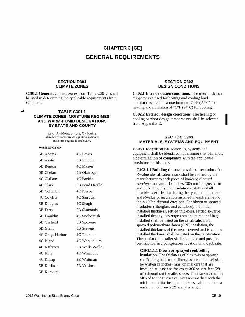
C301.1 General. Climate zones from Table C301.1 shall
be used in determining the applicable requirements from
Chapter 4.
TABLE C301.1 CLIMATE ZONES, MOISTURE REGIMES,
AND WARM-HUMID DESIGNATIONS BY STATE AND COUNTY
Key: A - Moist, B - Dry, C - Marine.
Absence of moisture designation indicates moisture regime is irrelevant.
WASHINGTON
5B Adams 4C Lewis
5B Asotin 5B Lincoln
5B Benton 4C Mason
5B Chelan 5B Okanogan
4C Clallam 4C Pacific
4C Clark 5B Pend Oreille
5B Columbia 4C Pierce
4C Cowlitz 4C San Juan
5B Douglas 4C Skagit
5B Ferry 5B Skamania
5B Franklin 4C Snohomish
5B Garfield 5B Spokane
5B Grant 5B Stevens
4C Grays Harbor 4C Thurston
4C Island 4C Wahkiakum
4C Jefferson 5B Walla Walla
4C King 4C Whatcom
4C Kitsap 5B Whitman
5B Kittitas 5B Yakima
5B Klickitat
SECTION C302 DESIGN CONDITIONS
C302.1 Interior design conditions. The interior design
temperatures used for heating and cooling load
calculations shall be a maximum of 72°F (22°C) for
heating and minimum of 75°F (24°C) for cooling.
C302.2 Exterior design conditions. The heating or
cooling outdoor design temperatures shall be selected
from Appendix C.
SECTION C303 MATERIALS, SYSTEMS AND EQUIPMENT
C303.1 Identification. Materials, systems and
equipment shall be identified in a manner that will allow
a determination of compliance with the applicable
provisions of this code.
C303.1.1 Building thermal envelope insulation. An
R-value identification mark shall be applied by the
manufacturer to each piece of building thermal
envelope insulation 12 inches (305 mm) or greater in
width. Alternately, the insulation installers shall
provide a certification listing the type, manufacturer
and R-value of insulation installed in each element of
the building thermal envelope. For blown or sprayed
insulation (fiberglass and cellulose), the initial
installed thickness, settled thickness, settled R-value,
installed density, coverage area and number of bags
installed shall be listed on the certification. For
sprayed polyurethane foam (SPF) insulation, the
installed thickness of the areas covered and R-value of
installed thickness shall be listed on the certification.
The insulation installer shall sign, date and post the
certification in a conspicuous location on the job site.
C303.1.1.1 Blown or sprayed roof/ceiling
insulation. The thickness of blown-in or sprayed
roof/ceiling insulation (fiberglass or cellulose) shall
be written in inches (mm) on markers that are
installed at least one for every 300 square feet (28
m2) throughout the attic space. The markers shall be
affixed to the trusses or joists and marked with the
minimum initial installed thickness with numbers a
minimum of 1 inch (25 mm) in height.
CE-20 2012 Washington State Energy Code
Each marker shall face the attic access opening.
Spray polyurethane foam thickness and installed
R-value shall be listed on certification provided by
the insulation installer.
C303.1.2 Insulation mark installation. Insulating
materials shall be installed such that the manufacturer's
R-value mark is readily observable upon inspection.
C303.1.3 Fenestration product rating. U-factors of
fenestration products (windows, doors and skylights)
shall be determined in accordance with NFRC 100 by
an accredited, independent laboratory, and labeled and
certified by the manufacturer. Products lacking such a
labeled U-factor shall be assigned a default U-factor
from Table C303.1.3(1), C303.1.3(2) or C303.1.3(4).
The solar heat gain coefficient (SHGC) and visible
transmittance (VT) of glazed fenestration products
(windows, glazed doors and skylights) shall be
determined in accordance with NFRC 200 by an
accredited, independent laboratory, and labeled and
certified by the manufacturer. Products lacking such a
labeled SHGC or VT shall be assigned a default SHGC
or VT from Table C303.1.3(3).
Exception: Units without NFRC ratings produced
by a small business may be assigned default
U-factors from Table C303.1.3(5) for vertical
fenestration.
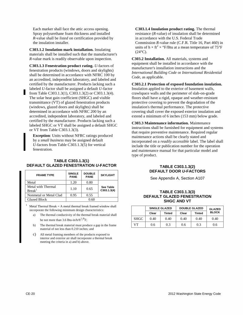
TABLE C303.1.3(1) DEFAULT GLAZED FENESTRATION U-FACTOR
FRAME TYPE SINGLE PANE
DOUBLE PANE
SKYLIGHT
Metal 1.20 0.80
See Table C303.1.3(4)
Metal with Thermal
Break1 1.10 0.65
Nonmetal or Metal Clad 0.95 0.55
Glazed Block 0.60
1 Metal Thermal Break .= A metal thermal break framed window shall
incorporate the following minimum design characteristics:
a) The thermal conductivity of the thermal break material shall
be not more than 3.6 Btu-in/h/ft2/°F;
b) The thermal break material must produce a gap in the frame
material of not less than 0.210 inches; and
c) All metal framing members of the products exposed to
interior and exterior air shall incorporate a thermal break meeting the criteria in a) and b) above.
C303.1.4 Insulation product rating. The thermal
resistance (R-value) of insulation shall be determined
in accordance with the U.S. Federal Trade
Commission R-value rule (C.F.R. Title 16, Part 460) in
units of h × ft2 × °F/Btu at a mean temperature of 75°F
(24°C).
C303.2 Installation. All materials, systems and
equipment shall be installed in accordance with the
manufacturer's installation instructions and the
International Building Code or International Residential
Code, as applicable.
C303.2.1 Protection of exposed foundation insulation.
Insulation applied to the exterior of basement walls,
crawlspace walls and the perimeter of slab-on-grade
floors shall have a rigid, opaque and weather-resistant
protective covering to prevent the degradation of the
insulation's thermal performance. The protective
covering shall cover the exposed exterior insulation and
extend a minimum of 6 inches (153 mm) below grade.
C303.3 Maintenance information. Maintenance
instructions shall be furnished for equipment and systems
that require preventive maintenance. Required regular
maintenance actions shall be clearly stated and
incorporated on a readily accessible label. The label shall
include the title or publication number for the operation
and maintenance manual for that particular model and
type of product.
TABLE C303.1.3(2) DEFAULT DOOR U-FACTORS
See Appendix A, Section A107
TABLE C303.1.3(3) DEFAULT GLAZED FENESTRATION
SHGC AND VT
SINGLE GLAZED DOUBLE GLAZED GLAZED
BLOCK Clear Tinted Clear Tinted
SHGC 0.40 0.40 0.40 0.40 0.40
VT 0.6 0.3 0.6 0.3 0.6
2012 Washington State Energy Code CE-21
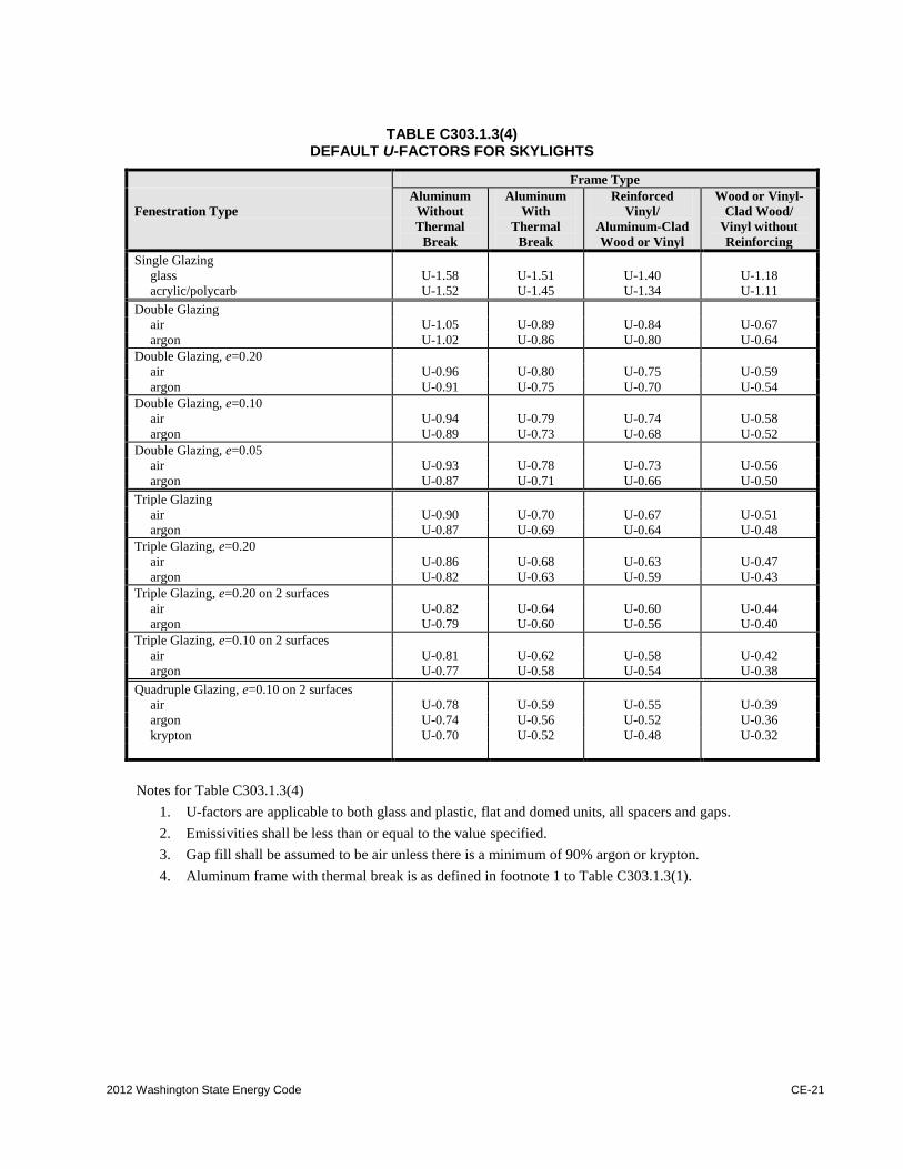
TABLE C303.1.3(4)
DEFAULT U-FACTORS FOR SKYLIGHTS
Frame Type
Fenestration Type
Aluminum
Without
Thermal
Break
Aluminum
With
Thermal
Break
Reinforced
Vinyl/
Aluminum-Clad
Wood or Vinyl
Wood or Vinyl-
Clad Wood/
Vinyl without
Reinforcing
Single Glazing
glass U-1.58 U-1.51 U-1.40 U-1.18
acrylic/polycarb U-1.52 U-1.45 U-1.34 U-1.11
Double Glazing
air U-1.05 U-0.89 U-0.84 U-0.67
argon U-1.02 U-0.86 U-0.80 U-0.64
Double Glazing, e=0.20
air U-0.96 U-0.80 U-0.75 U-0.59
argon U-0.91 U-0.75 U-0.70 U-0.54
Double Glazing, e=0.10
air U-0.94 U-0.79 U-0.74 U-0.58
argon U-0.89 U-0.73 U-0.68 U-0.52
Double Glazing, e=0.05
air U-0.93 U-0.78 U-0.73 U-0.56
argon U-0.87 U-0.71 U-0.66 U-0.50
Triple Glazing
air U-0.90 U-0.70 U-0.67 U-0.51
argon U-0.87 U-0.69 U-0.64 U-0.48
Triple Glazing, e=0.20
air U-0.86 U-0.68 U-0.63 U-0.47
argon U-0.82 U-0.63 U-0.59 U-0.43
Triple Glazing, e=0.20 on 2 surfaces
air U-0.82 U-0.64 U-0.60 U-0.44
argon U-0.79 U-0.60 U-0.56 U-0.40
Triple Glazing, e=0.10 on 2 surfaces
air U-0.81 U-0.62 U-0.58 U-0.42
argon U-0.77 U-0.58 U-0.54 U-0.38
Quadruple Glazing, e=0.10 on 2 surfaces
air U-0.78 U-0.59 U-0.55 U-0.39
argon U-0.74 U-0.56 U-0.52 U-0.36
krypton U-0.70 U-0.52 U-0.48 U-0.32
Notes for Table C303.1.3(4)
1. U-factors are applicable to both glass and plastic, flat and domed units, all spacers and gaps.
2. Emissivities shall be less than or equal to the value specified.
3. Gap fill shall be assumed to be air unless there is a minimum of 90% argon or krypton.
4. Aluminum frame with thermal break is as defined in footnote 1 to Table C303.1.3(1).
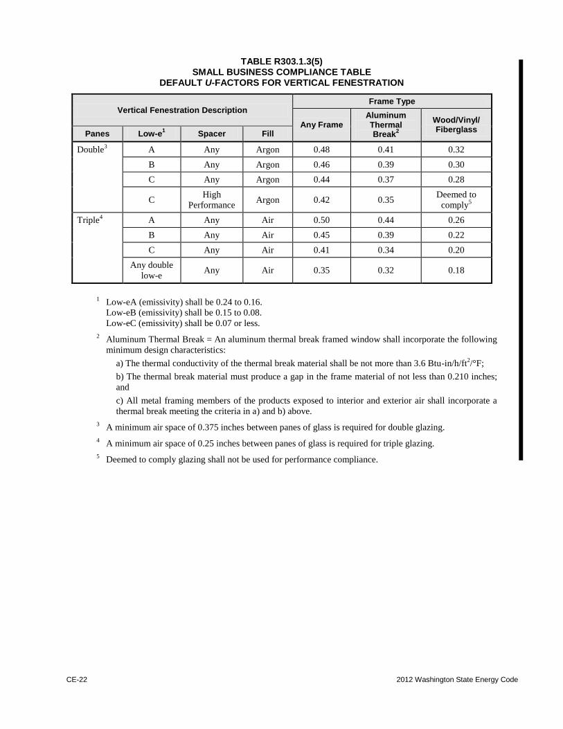
CE-22 2012 Washington State Energy Code
TABLE R303.1.3(5) SMALL BUSINESS COMPLIANCE TABLE
DEFAULT U-FACTORS FOR VERTICAL FENESTRATION
Vertical Fenestration Description Frame Type
Any Frame Aluminum Thermal Break
2
Wood/Vinyl/ Fiberglass
Panes Low-e1 Spacer Fill
Double3 A Any Argon 0.48 0.41 0.32
B Any Argon 0.46 0.39 0.30
C Any Argon 0.44 0.37 0.28
C High
Performance Argon 0.42 0.35
Deemed to
comply5
Triple4 A Any Air 0.50 0.44 0.26
B Any Air 0.45 0.39 0.22
C Any Air 0.41 0.34 0.20
Any double
low-e Any Air 0.35 0.32 0.18
1 Low-eA (emissivity) shall be 0.24 to 0.16.
Low-eB (emissivity) shall be 0.15 to 0.08.
Low-eC (emissivity) shall be 0.07 or less.
2 Aluminum Thermal Break = An aluminum thermal break framed window shall incorporate the following
minimum design characteristics:
a) The thermal conductivity of the thermal break material shall be not more than 3.6 Btu-in/h/ft2/°F;
b) The thermal break material must produce a gap in the frame material of not less than 0.210 inches;
and
c) All metal framing members of the products exposed to interior and exterior air shall incorporate a
thermal break meeting the criteria in a) and b) above.
3 A minimum air space of 0.375 inches between panes of glass is required for double glazing.
4 A minimum air space of 0.25 inches between panes of glass is required for triple glazing.
5 Deemed to comply glazing shall not be used for performance compliance.
2012 Washington State Energy Code CE-23
CHAPTER 4 [CE]
COMMERCIAL ENERGY EFFICIENCY
SECTION C401 GENERAL
C401.1 Scope. The requirements contained in this
chapter are applicable to commercial buildings, or
portions of commercial buildings.
C401.2 Application. Commercial buildings shall comply
with one of the following:
1. The requirements of Sections C402, C403, C404,
C405, C408 and C409.
2. The requirements of Section C407, C408, C409,
C402.4, C403.2, C404, C405.2, C405.3, C405.4,
C405.6 and C405.7. The building energy
consumption shall be equal to or less than 93
percent of the standard reference design building.
C401.2.1 Application to existing buildings.
Additions, alterations and repairs to existing buildings
shall comply with Sections C402, C403, C404, C405,
C408 and C409.
SECTION C402 BUILDING ENVELOPE REQUIREMENTS
C402.1 General (Prescriptive). The building thermal
envelope shall comply with Section C402.1.1. Section
C402.1.2 or Section C402.1.3 shall be permitted as an
alternative to the R-values specified in Section C402.1.1.
Walk-in coolers and walk-in freezers shall comply with
C402.5. Refrigerated warehouse coolers and refrigerated
warehouse freezers shall comply with C402.6.
Exception: Unstaffed equipment shelters or cabinets
used solely for personal wireless service facilities.
C402.1.1 Insulation and fenestration criteria. The
building thermal envelope shall meet the requirements
of Tables C402.2 and C402.3 based on the climate
zone specified in Chapter 3. Commercial buildings or
portions of commercial buildings enclosing Group R
occupancies shall use the R-values from the "Group R"
column of Table C402.2. Commercial buildings or
portions of commercial buildings enclosing
occupancies other than Group R shall use the R-values
from the "All other" column of Table C402.2.
C402.1.2 U-factor alternative. An assembly with a
U-factor, C-factor, or F-factor equal or less than that
specified in Table C402.1.2 shall be permitted as an
alternative to the R-value in Table C402.2.
Commercial buildings or portions of commercial
buildings enclosing Group R occupancies shall use the
U-factor, C-factor, or F-factor from the "Group R"
column of Table C402.1.2. Commercial buildings or
portions of commercial buildings enclosing
occupancies other than Group R shall use the U-factor,
C-factor or F-factor from the "All other" column of
Table C402.1.2. The U-factors for typical construction
assemblies are included in Appendix A. These values
shall be used for all calculations. Where proposed
construction assemblies are not represented in
Appendix A, values shall be calculated in accordance
with the ASHRAE Handbook -- Fundamentals using
the framing factors listed in Appendix A where
applicable and shall include the thermal bridging
effects of framing materials.
C402.1.3 Component performance building
envelope option.
C402.1.3.1 General. Buildings or structures whose
design heat loss rate (UAp) and solar heat gain
coefficient rate (SHGC • Ap) are less than or equal to
the target heat loss rate (UAt) and solar heat gain
coefficient rate (SHGC • At) shall be considered in
compliance with this section. The stated U-factor,
F-factor or allowable area of any component
assembly, listed in Table C402.1.2 and Table
C402.3, such as roof/ceiling, opaque wall, opaque
door, fenestration, floor over conditioned space,
slab-on-grade floor, radiant floor or opaque floor
may be increased and the U-factor or F-factor for
other components decreased, provided that the total
heat gain or loss for the entire building envelope
does not exceed the total resulting from compliance
to the U-factors, F-factors or allowable areas
specified in this section. Compliance shall be
calculated in total for the building envelope for
nonresidential spaces and for residential spaces.
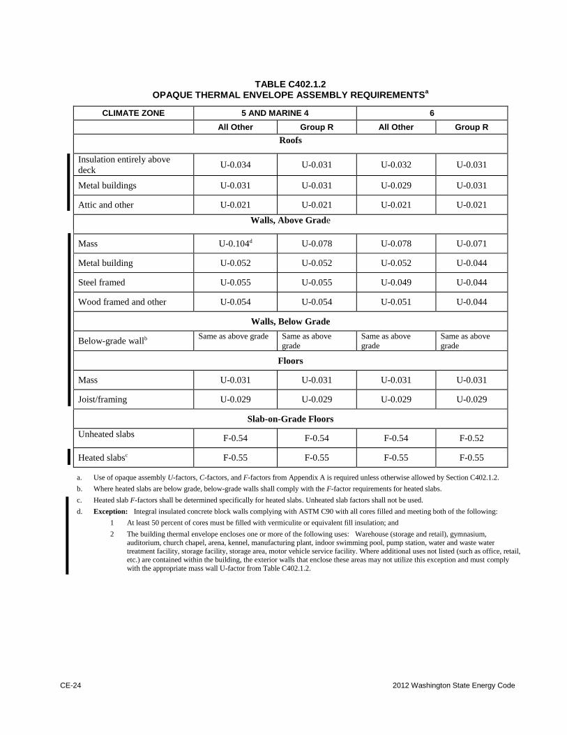
CE-24 2012 Washington State Energy Code
TABLE C402.1.2 OPAQUE THERMAL ENVELOPE ASSEMBLY REQUIREMENTS
a
CLIMATE ZONE 5 AND MARINE 4 6
All Other Group R All Other Group R
Roofs
Insulation entirely above
deck U-0.034 U-0.031 U-0.032 U-0.031
Metal buildings U-0.031 U-0.031 U-0.029 U-0.031
Attic and other U-0.021 U-0.021 U-0.021 U-0.021
Walls, Above Grade
Mass U-0.104d U-0.078 U-0.078 U-0.071
Metal building U-0.052 U-0.052 U-0.052 U-0.044
Steel framed U-0.055 U-0.055 U-0.049 U-0.044
Wood framed and other U-0.054 U-0.054 U-0.051 U-0.044
Walls, Below Grade
Below-grade wallb Same as above grade Same as above
grade
Same as above
grade
Same as above
grade
Floors
Mass U-0.031 U-0.031 U-0.031 U-0.031
Joist/framing U-0.029 U-0.029 U-0.029 U-0.029
Slab-on-Grade Floors
Unheated slabs F-0.54 F-0.54 F-0.54 F-0.52
Heated slabsc F-0.55 F-0.55 F-0.55 F-0.55
a. Use of opaque assembly U-factors, C-factors, and F-factors from Appendix A is required unless otherwise allowed by Section C402.1.2.
b. Where heated slabs are below grade, below-grade walls shall comply with the F-factor requirements for heated slabs.
c. Heated slab F-factors shall be determined specifically for heated slabs. Unheated slab factors shall not be used.
d. Exception: Integral insulated concrete block walls complying with ASTM C90 with all cores filled and meeting both of the following:
1 At least 50 percent of cores must be filled with vermiculite or equivalent fill insulation; and
2 The building thermal envelope encloses one or more of the following uses: Warehouse (storage and retail), gymnasium,
auditorium, church chapel, arena, kennel, manufacturing plant, indoor swimming pool, pump station, water and waste water
treatment facility, storage facility, storage area, motor vehicle service facility. Where additional uses not listed (such as office, retail,
etc.) are contained within the building, the exterior walls that enclose these areas may not utilize this exception and must comply
with the appropriate mass wall U-factor from Table C402.1.2.
2012 Washington State Energy Code CE-25
C402.1.3.2 Component U-factors. The U-factors
for typical construction assemblies are included in
Chapter 3 and Appendix A. These values shall be
used for all calculations. Where proposed
construction assemblies are not represented in
Chapter 3 or Appendix A, values shall be calculated
in accordance with the ASHRAE Handbook -
Fundamentals, using the framing factors listed in
Appendix A.
For envelope assemblies containing metal
framing, the U-factor shall be determined by one of
the following methods:
1. Results of laboratory measurements
according to acceptable methods of test.
2. ASHRAE Handbook - Fundamentals where
the metal framing is bonded on one or both
sides to a metal skin or covering.
3. The zone method as provided in ASHRAE
Handbook - Fundamentals.
4. Effective framing/cavity R-values as provided
in Appendix A. When return air ceiling
plenums are employed, the roof/ceiling
assembly shall:
a. For thermal transmittance purposes,
not include the ceiling proper nor the
plenum space as part of the assembly;
and
b. For gross area purposes, be based upon
the interior face of the upper plenum
surface.
5. Tables in ASHRAE 90.1-2010 Normative
Appendix A.
C402.1.3.3 UA calculations. The target UAt and the
proposed UAp shall be calculated using Equations
C402-1 and C402-2 and the corresponding areas and
U-factors from Table C402.1.2 and Table C402.3.
For the target UAt calculation, the skylights shall be
located in roof/ceiling area up to the maximum
skylight area per Section C402.3.1 and the
remainder of the fenestration allowed per Section
C402.3.1 shall be located in the wall area.
C402.1.3.4 SHGC rate calculations. Solar heat
gain coefficient shall comply with Table C402.3.
The target SHGCAt and the proposed SHGCAp shall
be calculated using Equations C402-3 and C402-4
and the corresponding areas and SHGCs from Table
C402.3.
C402.1.4 Semi-heated spaces. All spaces shall comply
with the requirements in Section C402 unless they meet
the definition for semi-heated spaces. For semi-heated
spaces, the building envelope shall comply with the same
requirements as that for conditioned spaces in Section
C402; however, for semi-heated spaces heated by other
than electric resistance heating equipment, wall
insulation is not required for those walls that separate
semi-heated spaces from the exterior provided that the
space meets all the requirements of semi-heated space.
Semi-heated spaces shall be calculated separately from
other conditioned spaces for compliance purposes.
Building envelope assemblies separating conditioned
space from semi-heated space shall comply with exterior
envelope insulation requirements. When choosing the
uninsulated wall option, the wall shall not be included in
Component Performance Building Envelope Option
calculation.
C402.2 Specific insulation requirements
(Prescriptive). Opaque assemblies shall comply
with Table C402.2. Where two or more layers of
continuous insulation board are used in a
construction assembly, the continuous insulation
boards shall be installed in accordance with Section
C303.2. If the continuous insulation board
manufacturer's installation instructions do not
address installation of two or more layers, the edge
joints between each layer of continuous insulation
boards shall be staggered.
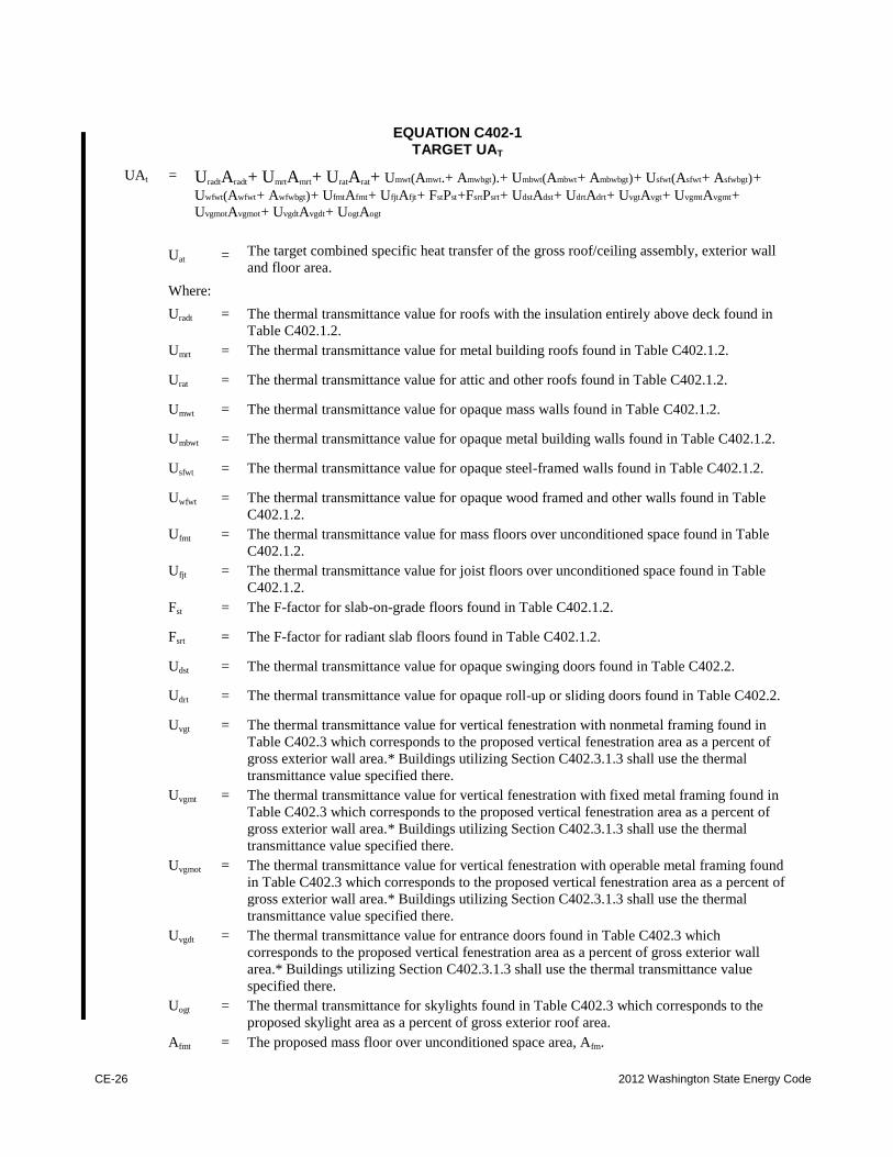
CE-26 2012 Washington State Energy Code
EQUATION C402-1
TARGET UAT
UAt .= UradtAradt .+ UmrtAmrt .+ UratArat .+ Umwt(Amwt.+ Amwbgt).+ Umbwt(Ambwt .+ Ambwbgt). + Usfwt(Asfwt .+ Asfwbgt). +
Uwfwt(Awfwt .+ Awfwbgt).+ UfmtAfmt .+ UfjtAfjt .+ FstPst .+FsrtPsrt .+ UdstAdst .+ UdrtAdrt .+ UvgtAvgt .+ UvgmtAvgmt .+
UvgmotAvgmot .+ UvgdtAvgdt .+ UogtAogt
Uat .= The target combined specific heat transfer of the gross roof/ceiling assembly, exterior wall
and floor area.
Where:
Uradt .= The thermal transmittance value for roofs with the insulation entirely above deck found in
Table C402.1.2.
Umrt .= The thermal transmittance value for metal building roofs found in Table C402.1.2.
Urat .= The thermal transmittance value for attic and other roofs found in Table C402.1.2.
Umwt .= The thermal transmittance value for opaque mass walls found in Table C402.1.2.
Umbwt .= The thermal transmittance value for opaque metal building walls found in Table C402.1.2.
Usfwt .= The thermal transmittance value for opaque steel-framed walls found in Table C402.1.2.
Uwfwt .= The thermal transmittance value for opaque wood framed and other walls found in Table
C402.1.2.
Ufmt .= The thermal transmittance value for mass floors over unconditioned space found in Table
C402.1.2.
Ufjt .= The thermal transmittance value for joist floors over unconditioned space found in Table
C402.1.2.
Fst .= The F-factor for slab-on-grade floors found in Table C402.1.2.
Fsrt .= The F-factor for radiant slab floors found in Table C402.1.2.
Udst .= The thermal transmittance value for opaque swinging doors found in Table C402.2.
Udrt .= The thermal transmittance value for opaque roll-up or sliding doors found in Table C402.2.
Uvgt .= The thermal transmittance value for vertical fenestration with nonmetal framing found in
Table C402.3 which corresponds to the proposed vertical fenestration area as a percent of
gross exterior wall area.* Buildings utilizing Section C402.3.1.3 shall use the thermal
transmittance value specified there.
Uvgmt .= The thermal transmittance value for vertical fenestration with fixed metal framing found in
Table C402.3 which corresponds to the proposed vertical fenestration area as a percent of
gross exterior wall area.* Buildings utilizing Section C402.3.1.3 shall use the thermal
transmittance value specified there.
Uvgmot .= The thermal transmittance value for vertical fenestration with operable metal framing found
in Table C402.3 which corresponds to the proposed vertical fenestration area as a percent of
gross exterior wall area.* Buildings utilizing Section C402.3.1.3 shall use the thermal
transmittance value specified there.
Uvgdt .= The thermal transmittance value for entrance doors found in Table C402.3 which
corresponds to the proposed vertical fenestration area as a percent of gross exterior wall
area.* Buildings utilizing Section C402.3.1.3 shall use the thermal transmittance value
specified there.
Uogt .= The thermal transmittance for skylights found in Table C402.3 which corresponds to the
proposed skylight area as a percent of gross exterior roof area.
Afmt .= The proposed mass floor over unconditioned space area, Afm.
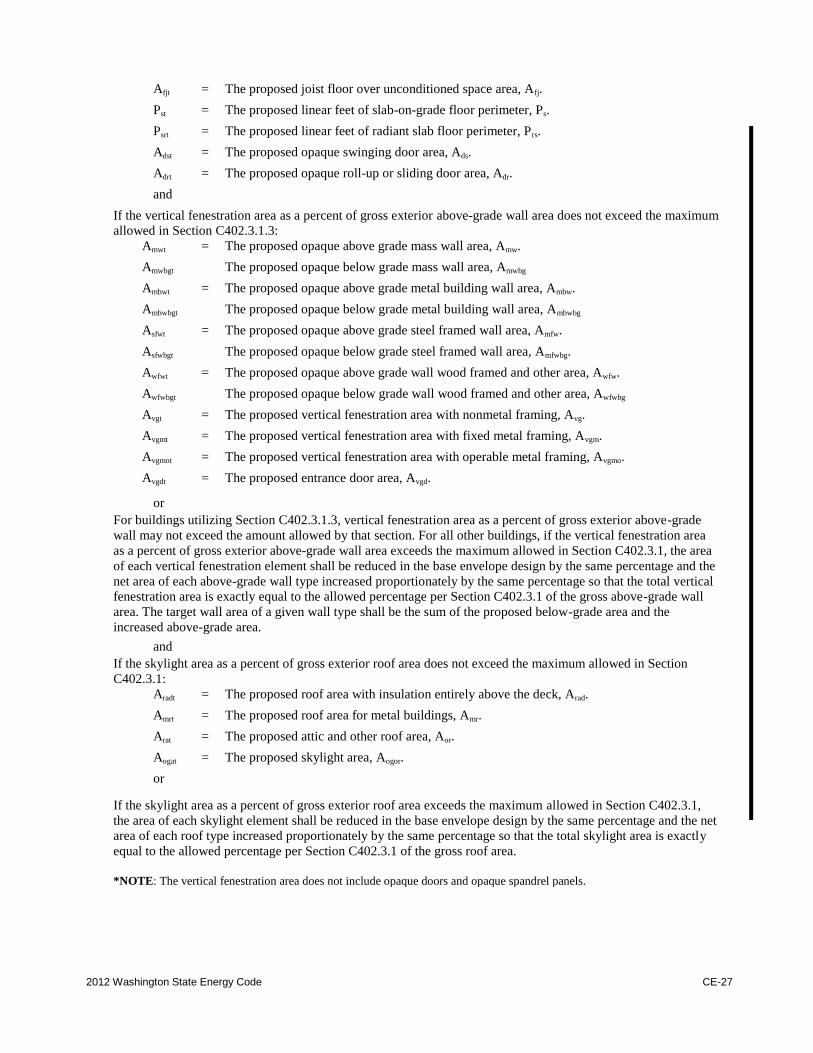
2012 Washington State Energy Code CE-27
Afjt .= The proposed joist floor over unconditioned space area, Afj.
Pst .= The proposed linear feet of slab-on-grade floor perimeter, Ps.
Psrt .= The proposed linear feet of radiant slab floor perimeter, Prs.
Adst .= The proposed opaque swinging door area, Ads.
Adrt .= The proposed opaque roll-up or sliding door area, Adr.
and
If the vertical fenestration area as a percent of gross exterior above-grade wall area does not exceed the maximum
allowed in Section C402.3.1.3:
Amwt .= The proposed opaque above grade mass wall area, Amw.
Amwbgt
The proposed opaque below grade mass wall area, Amwbg
Ambwt .= The proposed opaque above grade metal building wall area, Ambw.
Ambwbgt
The proposed opaque below grade metal building wall area, Ambwbg
Asfwt .= The proposed opaque above grade steel framed wall area, Amfw.
Asfwbgt
The proposed opaque below grade steel framed wall area, Amfwbg.
Awfwt .= The proposed opaque above grade wall wood framed and other area, Awfw.
Awfwbgt
The proposed opaque below grade wall wood framed and other area, Awfwbg
Avgt .= The proposed vertical fenestration area with nonmetal framing, Avg.
Avgmt .= The proposed vertical fenestration area with fixed metal framing, Avgm.
Avgmot .= The proposed vertical fenestration area with operable metal framing, Avgmo.
Avgdt .= The proposed entrance door area, Avgd.
or
For buildings utilizing Section C402.3.1.3, vertical fenestration area as a percent of gross exterior above-grade
wall may not exceed the amount allowed by that section. For all other buildings, if the vertical fenestration area
as a percent of gross exterior above-grade wall area exceeds the maximum allowed in Section C402.3.1, the area
of each vertical fenestration element shall be reduced in the base envelope design by the same percentage and the
net area of each above-grade wall type increased proportionately by the same percentage so that the total vertical
fenestration area is exactly equal to the allowed percentage per Section C402.3.1 of the gross above-grade wall
area. The target wall area of a given wall type shall be the sum of the proposed below-grade area and the
increased above-grade area. and
If the skylight area as a percent of gross exterior roof area does not exceed the maximum allowed in Section
C402.3.1:
Aradt .= The proposed roof area with insulation entirely above the deck, Arad.
Amrt .= The proposed roof area for metal buildings, Amr.
Arat .= The proposed attic and other roof area, Aor.
Aogat .= The proposed skylight area, Aogor.
or
If the skylight area as a percent of gross exterior roof area exceeds the maximum allowed in Section C402.3.1,
the area of each skylight element shall be reduced in the base envelope design by the same percentage and the net
area of each roof type increased proportionately by the same percentage so that the total skylight area is exactly
equal to the allowed percentage per Section C402.3.1 of the gross roof area.
*NOTE: The vertical fenestration area does not include opaque doors and opaque spandrel panels.
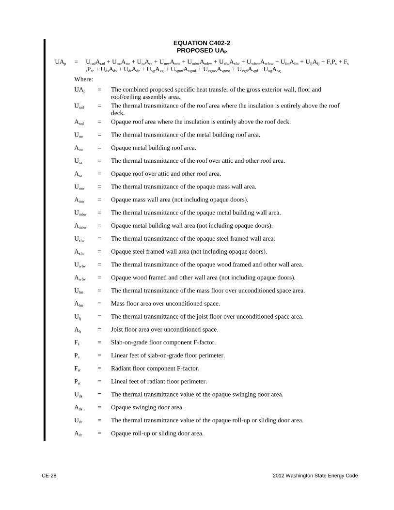
CE-28 2012 Washington State Energy Code
EQUATION C402-2 PROPOSED UAP
UAp .= UradArad .+ UmrAmr .+ UraAra .+ UmwAmw .+ UmbwAmbw .+ UsfwAsfw .+ UwfowAwfow .+ UfmAfm .+ UfjAfj .+ FsPs .+ Fs
rPsr .+ UdsAds .+ UdrAdr .+ UvgAvg .+ UvgmfAvgmf .+ UvgmoAvgmo .+ UvgdAvgd.+ UogAog
Where:
UAp .= The combined proposed specific heat transfer of the gross exterior wall, floor and
roof/ceiling assembly area.
Urad .= The thermal transmittance of the roof area where the insulation is entirely above the roof
deck.
Arad .= Opaque roof area where the insulation is entirely above the roof deck.
Umr .= The thermal transmittance of the metal building roof area.
Amr .= Opaque metal building roof area.
Ura .= The thermal transmittance of the roof over attic and other roof area.
Ara .= Opaque roof over attic and other roof area.
Umw .= The thermal transmittance of the opaque mass wall area.
Amw .= Opaque mass wall area (not including opaque doors).
Umbw .= The thermal transmittance of the opaque metal building wall area.
Ambw .= Opaque metal building wall area (not including opaque doors).
Usfw .= The thermal transmittance of the opaque steel framed wall area.
Asfw .= Opaque steel framed wall area (not including opaque doors).
Uwfw .= The thermal transmittance of the opaque wood framed and other wall area.
Awfw .= Opaque wood framed and other wall area (not including opaque doors).
Ufm .= The thermal transmittance of the mass floor over unconditioned space area.
Afm .= Mass floor area over unconditioned space.
Ufj .= The thermal transmittance of the joist floor over unconditioned space area.
Afj .= Joist floor area over unconditioned space.
Fs .= Slab-on-grade floor component F-factor.
Ps .= Linear feet of slab-on-grade floor perimeter.
Fsr .= Radiant floor component F-factor.
Psr .= Lineal feet of radiant floor perimeter.
Uds .= The thermal transmittance value of the opaque swinging door area.
Ads .= Opaque swinging door area.
Udr .= The thermal transmittance value of the opaque roll-up or sliding door area.
Adr .= Opaque roll-up or sliding door area.
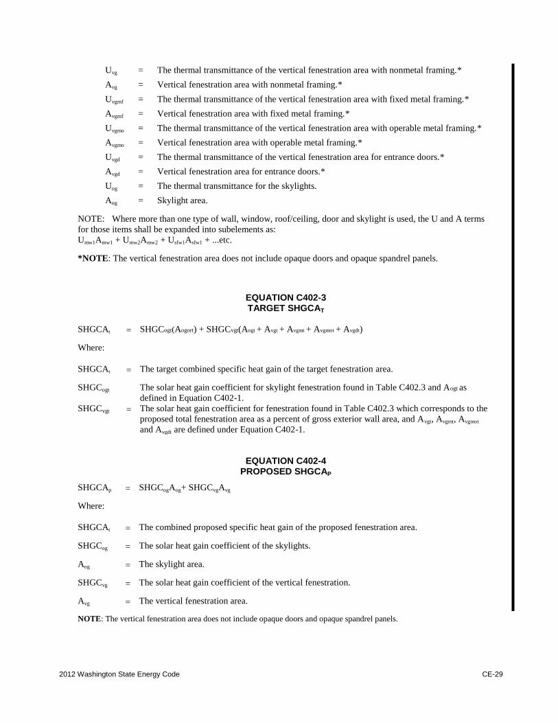
2012 Washington State Energy Code CE-29
Uvg .= The thermal transmittance of the vertical fenestration area with nonmetal framing.*
Avg .= Vertical fenestration area with nonmetal framing.*
Uvgmf .= The thermal transmittance of the vertical fenestration area with fixed metal framing.*
Avgmf .= Vertical fenestration area with fixed metal framing.*
Uvgmo .= The thermal transmittance of the vertical fenestration area with operable metal framing.*
Avgmo .= Vertical fenestration area with operable metal framing.*
Uvgd .= The thermal transmittance of the vertical fenestration area for entrance doors.*
Avgd .= Vertical fenestration area for entrance doors.*
Uog .= The thermal transmittance for the skylights.
Aog .= Skylight area.
NOTE: Where more than one type of wall, window, roof/ceiling, door and skylight is used, the U and A terms
for those items shall be expanded into subelements as: Umw1Amw1 .+ Umw2Amw2 .+ Usfw1Asfw1 .+ ...etc.
*NOTE: The vertical fenestration area does not include opaque doors and opaque spandrel panels.
EQUATION C402-3 TARGET SHGCAT
SHGCAt
.
= SHGCogt(Aogort) + SHGCvgt(Aogt .+ Avgt .+ Avgmt .+ Avgmot .+ Avgdt)
Where:
SHGCAt
.
= The target combined specific heat gain of the target fenestration area.
SHGCogt
The solar heat gain coefficient for skylight fenestration found in Table C402.3 and Aogt as
defined in Equation C402-1. SHGCvgt
.
= The solar heat gain coefficient for fenestration found in Table C402.3 which corresponds to the
proposed total fenestration area as a percent of gross exterior wall area, and Avgt, Avgmt, Avgmot
and Avgdt are defined under Equation C402-1.
EQUATION C402-4 PROPOSED SHGCAP
SHGCAp .
= SHGCogAog.+ SHGCvgAvg
Where:
SHGCAt
.
= The combined proposed specific heat gain of the proposed fenestration area.
SHGCog .
= The solar heat gain coefficient of the skylights.
Aog .
= The skylight area.
SHGCvg .
= The solar heat gain coefficient of the vertical fenestration.
Avg .
= The vertical fenestration area.
NOTE: The vertical fenestration area does not include opaque doors and opaque spandrel panels.
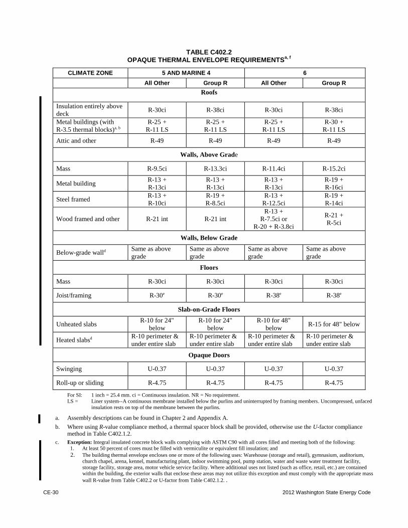
CE-30 2012 Washington State Energy Code
TABLE C402.2
OPAQUE THERMAL ENVELOPE REQUIREMENTSa, f
CLIMATE ZONE 5 AND MARINE 4 6
All Other Group R All Other Group R
Roofs
Insulation entirely above
deck R-30ci R-38ci R-30ci R-38ci
Metal buildings (with
R-3.5 thermal blocks)a, b R-25 .+
R-11 LS R-25 .+
R-11 LS R-25 .+
R-11 LS R-30 .+
R-11 LS
Attic and other R-49 R-49 R-49 R-49
Walls, Above Grade
Mass R-9.5ci R-13.3ci R-11.4ci R-15.2ci
Metal building R-13 .+
R-13ci R-13 .+
R-13ci R-13 .+
R-13ci R-19 .+
R-16ci
Steel framed R-13 .+
R-10ci R-19 .+
R-8.5ci R-13 .+
R-12.5ci R-19 .+
R-14ci
Wood framed and other R-21 int R-21 int R-13 .+
R-7.5ci or
R-20 .+ R-3.8ci
R-21 .+
R-5ci
Walls, Below Grade
Below-grade walld Same as above
grade Same as above
grade Same as above
grade Same as above
grade
Floors
Mass R-30ci R-30ci R-30ci R-30ci
Joist/framing R-30e R-30e R-38e R-38e
Slab-on-Grade Floors
Unheated slabs R-10 for 24"
below R-10 for 24"
below R-10 for 48"
below R-15 for 48" below
Heated slabsd R-10 perimeter &
under entire slab R-10 perimeter &
under entire slab R-10 perimeter &
under entire slab R-10 perimeter &
under entire slab
Opaque Doors
Swinging U-0.37 U-0.37 U-0.37 U-0.37
Roll-up or sliding R-4.75 R-4.75 R-4.75 R-4.75
For SI: 1 inch .= 25.4 mm. ci .= Continuous insulation. NR .= No requirement.
LS .= Liner system--A continuous membrane installed below the purlins and uninterrupted by framing members. Uncompressed, unfaced
insulation rests on top of the membrane between the purlins.
a. Assembly descriptions can be found in Chapter 2 and Appendix A.
b. Where using R-value compliance method, a thermal spacer block shall be provided, otherwise use the U-factor compliance
method in Table C402.1.2.
c. Exception: Integral insulated concrete block walls complying with ASTM C90 with all cores filled and meeting both of the following:
1. At least 50 percent of cores must be filled with vermiculite or equivalent fill insulation; and
2. The building thermal envelope encloses one or more of the following uses: Warehouse (storage and retail), gymnasium, auditorium,
church chapel, arena, kennel, manufacturing plant, indoor swimming pool, pump station, water and waste water treatment facility,
storage facility, storage area, motor vehicle service facility. Where additional uses not listed (such as office, retail, etc.) are contained within the building, the exterior walls that enclose these areas may not utilize this exception and must comply with the appropriate mass
wall R-value from Table C402.2 or U-factor from Table C402.1.2. .
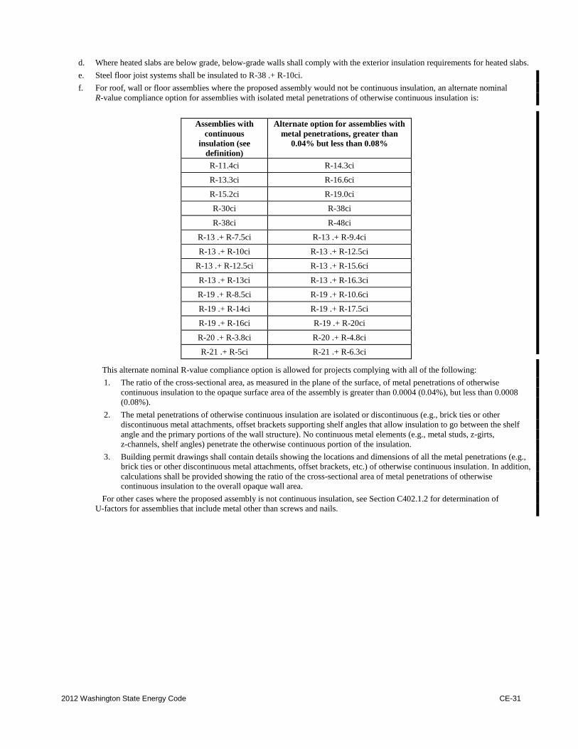
2012 Washington State Energy Code CE-31
d. Where heated slabs are below grade, below-grade walls shall comply with the exterior insulation requirements for heated slabs.
e. Steel floor joist systems shall be insulated to R-38 .+ R-10ci.
f. For roof, wall or floor assemblies where the proposed assembly would not be continuous insulation, an alternate nominal
R-value compliance option for assemblies with isolated metal penetrations of otherwise continuous insulation is:
Assemblies with
continuous
insulation (see
definition)
Alternate option for assemblies with
metal penetrations, greater than
0.04% but less than 0.08%
R-11.4ci R-14.3ci
R-13.3ci R-16.6ci
R-15.2ci R-19.0ci
R-30ci R-38ci
R-38ci R-48ci
R-13 .+ R-7.5ci R-13 .+ R-9.4ci
R-13 .+ R-10ci R-13 .+ R-12.5ci
R-13 .+ R-12.5ci R-13 .+ R-15.6ci
R-13 .+ R-13ci R-13 .+ R-16.3ci
R-19 .+ R-8.5ci R-19 .+ R-10.6ci
R-19 .+ R-14ci R-19 .+ R-17.5ci
R-19 .+ R-16ci R-19 .+ R-20ci
R-20 .+ R-3.8ci R-20 .+ R-4.8ci
R-21 .+ R-5ci R-21 .+ R-6.3ci
This alternate nominal R-value compliance option is allowed for projects complying with all of the following:
1. The ratio of the cross-sectional area, as measured in the plane of the surface, of metal penetrations of otherwise
continuous insulation to the opaque surface area of the assembly is greater than 0.0004 (0.04%), but less than 0.0008
(0.08%).
2. The metal penetrations of otherwise continuous insulation are isolated or discontinuous (e.g., brick ties or other
discontinuous metal attachments, offset brackets supporting shelf angles that allow insulation to go between the shelf
angle and the primary portions of the wall structure). No continuous metal elements (e.g., metal studs, z-girts,
z-channels, shelf angles) penetrate the otherwise continuous portion of the insulation.
3. Building permit drawings shall contain details showing the locations and dimensions of all the metal penetrations (e.g.,
brick ties or other discontinuous metal attachments, offset brackets, etc.) of otherwise continuous insulation. In addition,
calculations shall be provided showing the ratio of the cross-sectional area of metal penetrations of otherwise
continuous insulation to the overall opaque wall area.
For other cases where the proposed assembly is not continuous insulation, see Section C402.1.2 for determination of
U-factors for assemblies that include metal other than screws and nails.
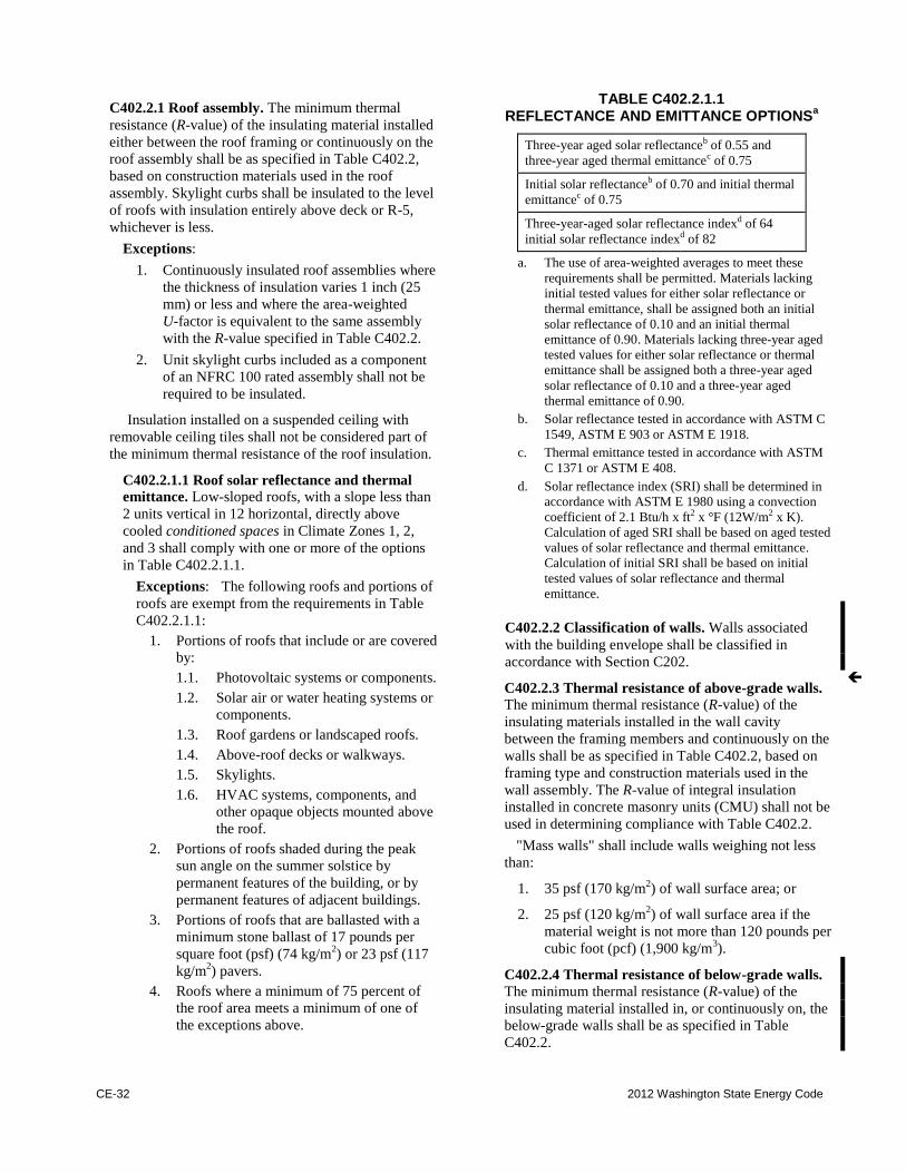
CE-32 2012 Washington State Energy Code
C402.2.1 Roof assembly. The minimum thermal
resistance (R-value) of the insulating material installed
either between the roof framing or continuously on the
roof assembly shall be as specified in Table C402.2,
based on construction materials used in the roof
assembly. Skylight curbs shall be insulated to the level
of roofs with insulation entirely above deck or R-5,
whichever is less.
Exceptions:
1. Continuously insulated roof assemblies where
the thickness of insulation varies 1 inch (25
mm) or less and where the area-weighted
U-factor is equivalent to the same assembly
with the R-value specified in Table C402.2.
2. Unit skylight curbs included as a component
of an NFRC 100 rated assembly shall not be
required to be insulated.
Insulation installed on a suspended ceiling with
removable ceiling tiles shall not be considered part of
the minimum thermal resistance of the roof insulation.
C402.2.1.1 Roof solar reflectance and thermal
emittance. Low-sloped roofs, with a slope less than
2 units vertical in 12 horizontal, directly above
cooled conditioned spaces in Climate Zones 1, 2,
and 3 shall comply with one or more of the options
in Table C402.2.1.1.
Exceptions: The following roofs and portions of
roofs are exempt from the requirements in Table
C402.2.1.1:
1. Portions of roofs that include or are covered
by:
1.1. Photovoltaic systems or components.
1.2. Solar air or water heating systems or
components.
1.3. Roof gardens or landscaped roofs.
1.4. Above-roof decks or walkways.
1.5. Skylights.
1.6. HVAC systems, components, and
other opaque objects mounted above
the roof.
2. Portions of roofs shaded during the peak
sun angle on the summer solstice by
permanent features of the building, or by
permanent features of adjacent buildings.
3. Portions of roofs that are ballasted with a
minimum stone ballast of 17 pounds per
square foot (psf) (74 kg/m2) or 23 psf (117
kg/m2) pavers.
4. Roofs where a minimum of 75 percent of
the roof area meets a minimum of one of
the exceptions above.
TABLE C402.2.1.1 REFLECTANCE AND EMITTANCE OPTIONS
a
Three-year aged solar reflectanceb of 0.55 and
three-year aged thermal emittancec of 0.75
Initial solar reflectanceb of 0.70 and initial thermal
emittancec of 0.75
Three-year-aged solar reflectance indexd of 64
initial solar reflectance indexd of 82
a. The use of area-weighted averages to meet these
requirements shall be permitted. Materials lacking
initial tested values for either solar reflectance or
thermal emittance, shall be assigned both an initial
solar reflectance of 0.10 and an initial thermal
emittance of 0.90. Materials lacking three-year aged
tested values for either solar reflectance or thermal
emittance shall be assigned both a three-year aged
solar reflectance of 0.10 and a three-year aged
thermal emittance of 0.90.
b. Solar reflectance tested in accordance with ASTM C
1549, ASTM E 903 or ASTM E 1918.
c. Thermal emittance tested in accordance with ASTM
C 1371 or ASTM E 408.
d. Solar reflectance index (SRI) shall be determined in
accordance with ASTM E 1980 using a convection
coefficient of 2.1 Btu/h x ft2 x °F (12W/m2 x K).
Calculation of aged SRI shall be based on aged tested
values of solar reflectance and thermal emittance.
Calculation of initial SRI shall be based on initial
tested values of solar reflectance and thermal
emittance.
C402.2.2 Classification of walls. Walls associated
with the building envelope shall be classified in
accordance with Section C202.
C402.2.3 Thermal resistance of above-grade walls.
The minimum thermal resistance (R-value) of the
insulating materials installed in the wall cavity
between the framing members and continuously on the
walls shall be as specified in Table C402.2, based on
framing type and construction materials used in the
wall assembly. The R-value of integral insulation
installed in concrete masonry units (CMU) shall not be
used in determining compliance with Table C402.2.
"Mass walls" shall include walls weighing not less
than:
1. 35 psf (170 kg/m2) of wall surface area; or
2. 25 psf (120 kg/m2) of wall surface area if the
material weight is not more than 120 pounds per
cubic foot (pcf) (1,900 kg/m3).
C402.2.4 Thermal resistance of below-grade walls.
The minimum thermal resistance (R-value) of the
insulating material installed in, or continuously on, the
below-grade walls shall be as specified in Table
C402.2.
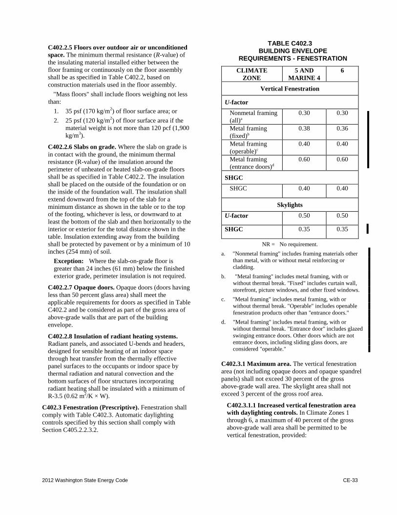
2012 Washington State Energy Code CE-33
C402.2.5 Floors over outdoor air or unconditioned
space. The minimum thermal resistance (R-value) of
the insulating material installed either between the
floor framing or continuously on the floor assembly
shall be as specified in Table C402.2, based on
construction materials used in the floor assembly.
"Mass floors" shall include floors weighing not less
than:
1. 35 psf (170 kg/m2) of floor surface area; or
2. 25 psf (120 kg/m2) of floor surface area if the
material weight is not more than 120 pcf (1,900
kg/m3).
C402.2.6 Slabs on grade. Where the slab on grade is
in contact with the ground, the minimum thermal
resistance (R-value) of the insulation around the
perimeter of unheated or heated slab-on-grade floors
shall be as specified in Table C402.2. The insulation
shall be placed on the outside of the foundation or on
the inside of the foundation wall. The insulation shall
extend downward from the top of the slab for a
minimum distance as shown in the table or to the top
of the footing, whichever is less, or downward to at
least the bottom of the slab and then horizontally to the
interior or exterior for the total distance shown in the
table. Insulation extending away from the building
shall be protected by pavement or by a minimum of 10
inches (254 mm) of soil.
Exception: Where the slab-on-grade floor is
greater than 24 inches (61 mm) below the finished
exterior grade, perimeter insulation is not required.
C402.2.7 Opaque doors. Opaque doors (doors having
less than 50 percent glass area) shall meet the
applicable requirements for doors as specified in Table
C402.2 and be considered as part of the gross area of
above-grade walls that are part of the building
envelope.
C402.2.8 Insulation of radiant heating systems.
Radiant panels, and associated U-bends and headers,
designed for sensible heating of an indoor space
through heat transfer from the thermally effective
panel surfaces to the occupants or indoor space by
thermal radiation and natural convection and the
bottom surfaces of floor structures incorporating
radiant heating shall be insulated with a minimum of
R-3.5 (0.62 m2/K × W).
C402.3 Fenestration (Prescriptive). Fenestration shall
comply with Table C402.3. Automatic daylighting
controls specified by this section shall comply with
Section C405.2.2.3.2.
TABLE C402.3 BUILDING ENVELOPE
REQUIREMENTS - FENESTRATION
CLIMATE
ZONE 5 AND
MARINE 4 6
Vertical Fenestration
U-factor
Nonmetal framing
(all)a 0.30 0.30
Metal framing
(fixed)b 0.38 0.36
Metal framing
(operable)c 0.40 0.40
Metal framing
(entrance doors)d 0.60 0.60
SHGC
SHGC 0.40 0.40
Skylights
U-factor 0.50 0.50
SHGC 0.35 0.35
NR = No requirement.
a. "Nonmetal framing" includes framing materials other
than metal, with or without metal reinforcing or
cladding.
b. "Metal framing" includes metal framing, with or
without thermal break. "Fixed" includes curtain wall,
storefront, picture windows, and other fixed windows.
c. "Metal framing" includes metal framing, with or
without thermal break. "Operable" includes openable
fenestration products other than "entrance doors."
d. "Metal framing" includes metal framing, with or
without thermal break. "Entrance door" includes glazed
swinging entrance doors. Other doors which are not
entrance doors, including sliding glass doors, are
considered "operable."
C402.3.1 Maximum area. The vertical fenestration
area (not including opaque doors and opaque spandrel
panels) shall not exceed 30 percent of the gross
above-grade wall area. The skylight area shall not
exceed 3 percent of the gross roof area.
C402.3.1.1 Increased vertical fenestration area
with daylighting controls. In Climate Zones 1
through 6, a maximum of 40 percent of the gross
above-grade wall area shall be permitted to be
vertical fenestration, provided:
CE-34 2012 Washington State Energy Code
1. No less than 50 percent of the conditioned floor
area is within a daylight zone;
2. Automatic daylighting controls are installed in
daylight zones; and
3. Visible transmittance (VT) of vertical
fenestration is greater than or equal to 1.1 times
solar heat gain coefficient (SHGC).
Exception: Fenestration that is outside the scope
of NFRC 200 is not required to comply with Item
3.
C402.3.1.2 Increased skylight area with daylighting
controls. The skylight area shall be permitted to be a
maximum of 5 percent of the roof area provided
automatic daylighting controls are installed in daylight
zones under skylights.
C402.3.1.3 Increased vertical fenestration area with
high-performance fenestration. The vertical
fenestration area (not including opaque doors and
opaque spandrel panels) is permitted to exceed 30% but
shall not exceed 40% of the gross above grade wall
area, for the purpose of prescriptive compliance with
Section C402.1.2 or for the Target UA calculation in
Equation C402-1, provided that each of the following
conditions are met:
1. The vertical fenestration shall have the following
U-factors:
a. Non-metal framing (all) = 0.28
b. Metal framing (fixed) = 0.34
c. Metal framing (operable) = 0.36
d. Metal framing (entrance doors) = 0.60
2. The SHGC of the vertical fenestration shall be less
than or equal to 0.35, adjusted for projection factor
in compliance with C402.3.3.1.
The compliance path described in this section is not
permitted to be used for the Total Building
Performance compliance path in Section C407.
C402.3.2 Minimum skylight fenestration area. For
single story buildings only, in an enclosed space greater
than 10,000 square feet (929 m2), directly under a roof
with ceiling heights greater than 15 feet (4572 mm),
and used as an office, lobby, atrium, concourse,
corridor, gymnasium/exercise center, convention
center, automotive service, manufacturing,
nonrefrigerated warehouse, retail store,
distribution/sorting area, transportation, or workshop,
the total daylight zone under skylights shall be not less
than half the floor area and shall provide a minimum
skylight area to daylight zone under skylights of either:
1. Not less than 3 percent with a skylight VT of at
least 0.40; or
2. Provide a minimum skylight effective aperture of
at least 1 percent determined in accordance with
Equation C4-1.
Skylight Effective Aperture = (085 x Skylight Area x Skylight VT x WF) Daylight zone under skylight
(Equation C4-1) where:
Skylight area = Total fenestration area of skylights.
Skylight VT = Area weighted average visible
transmittance of skylights.
WF = Area weighted average well factor,
where well factor is 0.9 if light well
depth is less than 2 feet (610 mm), or
0.7 if light well depth is 2 feet (610
mm) or greater.
Light well depth = Measure vertically from the underside
of the lowest point of the skylight
glazing to the ceiling plane under the
skylight.
Exception: Skylights above daylight zones of
enclosed spaces are not required in:
1. Buildings in Climate Zones 6 through 8.
2. Spaces where the designed general lighting
power densities are less than 0.5 W/ft2 (5.4
W/m2).
3. Areas where it is documented that existing
structures or natural objects block direct beam
sunlight on at least half of the roof over the
enclosed area for more than 1,500 daytime
hours per year between 8 a.m. and 4 p.m.
4. Spaces where the daylight zone under rooftop
monitors is greater than 50 percent of the
enclosed space floor area.
C402.3.2.1 Lighting controls in daylight zones under
skylights. All lighting in the daylight zone shall be
controlled by automatic daylighting controls that
comply with Section C405.2.2.3.2.
Exception: Skylights above daylight zones of
enclosed spaces are not required in:
1. Buildings in Climate Zones 6 through 8.
2. Spaces where the designed general lighting
power densities are less than 0.5 W/ft2 (5.4
W/m2).
3. Areas where it is documented that existing
structures or natural objects block direct beam
sunlight on at least half of the roof over the
enclosed area for more than 1,500 daytime
hours per year between 8 a.m. and 4 p.m.
4. Spaces where the daylight zone under rooftop
monitors is greater than 50 percent of the
enclosed space floor area.
C402.3.2.2 Haze factor. Skylights in office, storage,
automotive service, manufacturing, nonrefrigerated
warehouse, retail store, and distribution/sorting area
spaces shall have a glazing material or diffuser with a
measured haze factor greater than 90 percent when
tested in accordance with ASTM D 1003.
Exception: Skylights designed to exclude direct
sunlight entering the occupied space by the use of
fixed or automated baffles, or the geometry of
skylight and light well need not comply with Section
C402.3.2.2.
C402.3.3 Maximum U-factor and SHGC. For vertical
fenestration, the maximum U-factor and solar heat gain
coefficient (SHGC) shall be as specified in Table C402.3,
based on the window projection factor. For skylights, the
maximum U-factor and solar heat gain coefficient
(SHGC) shall be as specified in Table C402.3.
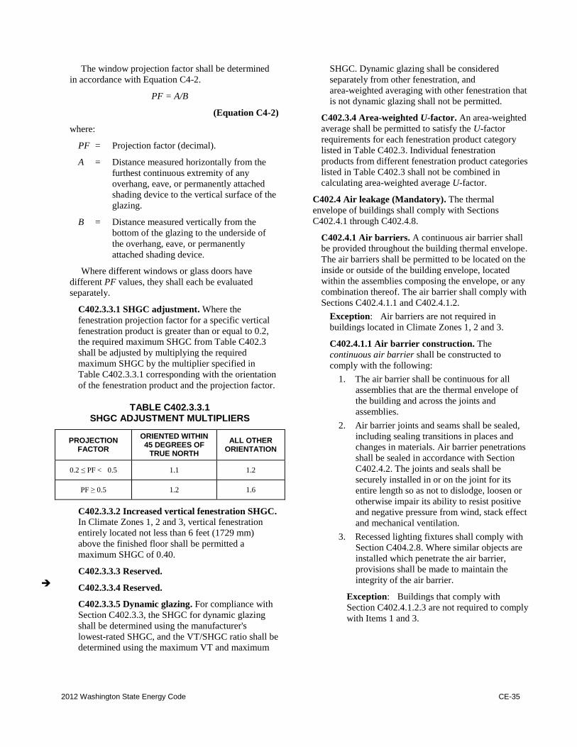
2012 Washington State Energy Code CE-35
The window projection factor shall be determined
in accordance with Equation C4-2.
PF = A/B
(Equation C4-2)
where:
PF = Projection factor (decimal).
A = Distance measured horizontally from the
furthest continuous extremity of any
overhang, eave, or permanently attached
shading device to the vertical surface of the
glazing.
B = Distance measured vertically from the
bottom of the glazing to the underside of
the overhang, eave, or permanently
attached shading device.
Where different windows or glass doors have
different PF values, they shall each be evaluated
separately.
C402.3.3.1 SHGC adjustment. Where the
fenestration projection factor for a specific vertical
fenestration product is greater than or equal to 0.2,
the required maximum SHGC from Table C402.3
shall be adjusted by multiplying the required
maximum SHGC by the multiplier specified in
Table C402.3.3.1 corresponding with the orientation
of the fenestration product and the projection factor.
TABLE C402.3.3.1 SHGC ADJUSTMENT MULTIPLIERS
PROJECTION FACTOR
ORIENTED WITHIN 45 DEGREES OF
TRUE NORTH ALL OTHER
ORIENTATION
0.2 ≤ PF < 0.5 1.1 1.2
PF ≥ 0.5 1.2 1.6
C402.3.3.2 Increased vertical fenestration SHGC.
In Climate Zones 1, 2 and 3, vertical fenestration
entirely located not less than 6 feet (1729 mm)
above the finished floor shall be permitted a
maximum SHGC of 0.40.
C402.3.3.3 Reserved.
C402.3.3.4 Reserved.
C402.3.3.5 Dynamic glazing. For compliance with
Section C402.3.3, the SHGC for dynamic glazing
shall be determined using the manufacturer's
lowest-rated SHGC, and the VT/SHGC ratio shall be
determined using the maximum VT and maximum
SHGC. Dynamic glazing shall be considered
separately from other fenestration, and
area-weighted averaging with other fenestration that
is not dynamic glazing shall not be permitted.
C402.3.4 Area-weighted U-factor. An area-weighted
average shall be permitted to satisfy the U-factor
requirements for each fenestration product category
listed in Table C402.3. Individual fenestration
products from different fenestration product categories
listed in Table C402.3 shall not be combined in
calculating area-weighted average U-factor.
C402.4 Air leakage (Mandatory). The thermal
envelope of buildings shall comply with Sections
C402.4.1 through C402.4.8.
C402.4.1 Air barriers. A continuous air barrier shall
be provided throughout the building thermal envelope.
The air barriers shall be permitted to be located on the
inside or outside of the building envelope, located
within the assemblies composing the envelope, or any
combination thereof. The air barrier shall comply with
Sections C402.4.1.1 and C402.4.1.2.
Exception: Air barriers are not required in
buildings located in Climate Zones 1, 2 and 3.
C402.4.1.1 Air barrier construction. The
continuous air barrier shall be constructed to
comply with the following:
1. The air barrier shall be continuous for all
assemblies that are the thermal envelope of
the building and across the joints and
assemblies.
2. Air barrier joints and seams shall be sealed,
including sealing transitions in places and
changes in materials. Air barrier penetrations
shall be sealed in accordance with Section
C402.4.2. The joints and seals shall be
securely installed in or on the joint for its
entire length so as not to dislodge, loosen or
otherwise impair its ability to resist positive
and negative pressure from wind, stack effect
and mechanical ventilation.
3. Recessed lighting fixtures shall comply with
Section C404.2.8. Where similar objects are
installed which penetrate the air barrier,
provisions shall be made to maintain the
integrity of the air barrier.
Exception: Buildings that comply with
Section C402.4.1.2.3 are not required to comply
with Items 1 and 3.
CE-36 2012 Washington State Energy Code
C402.4.1.2 Air barrier compliance options. A
continuous air barrier for the opaque building
envelope shall comply with Section C402.4.1.2.3.
C402.4.1.2.1 Materials. Materials with an air
permeability no greater than 0.004 cfm/ft2 (0.02
2) under a pressure differential of 0.3
inches water gauge (w.g.) (75 Pa) when tested in
accordance with ASTM E 2178 shall comply with
this section. Materials in Items 1 through 15 shall
be deemed to comply with this section provided
joints are sealed and materials are installed as air
barriers in accordance with the manufacturer's
instructions.
1. Plywood with a thickness of not less than
3/8 inch (10 mm).
2. Oriented strand board having a thickness of
not less than 3/8 inch (10 mm).
3. Extruded polystyrene insulation board
having a thickness of not less than 1/2 inch
(12 mm).
4. Foil-back polyisocyanurate insulation board
having a thickness of not less than 1/2 inch
(12 mm).
5. Closed cell spray foam a minimum density
of 1.5 pcf (2.4 kg/m3) having a thickness of
not less than 1 1/2 inches (36 mm).
6. Open cell spray foam with a density
between 0.4 and 1.5 pcf (0.6 and 2.4 kg/m3)
and having a thickness of not less than 4.5
inches (113 mm).
7. Exterior or interior gypsum board having a
thickness of not less than 1/2 inch (12 mm).
8. Cement board having a thickness of not less
than 1/2 inch (12 mm).
9. Built up roofing membrane.
10. Modified bituminous roof membrane.
11. Fully adhered single-ply roof membrane.
12. A Portland cement/sand parge, or gypsum
plaster having a thickness of not less than
5/8 inch (16 mm).
13. Cast-in-place and precast concrete.
14. Fully grouted concrete block masonry.
15. Sheet steel or aluminum.
C402.4.1.2.2 Assemblies. Assemblies of materials
and components with an average air leakage not to
exceed 0.04 cfm/ft2
2) under a
pressure differential of 0.3 inches of water gauge
(w.g.)(75 Pa) when tested in accordance with
ASTM E 2357, ASTM E 1677 or ASTM E
283 shall comply with this section. Assemblies
listed in Items 1 and 2 shall be deemed to comply
provided joints are sealed and requirements of
Section C402.4.1.1 are met.
1. Concrete masonry walls coated with one
application either of block filler and two
applications of a paint or sealer coating;
2. A Portland cement/sand parge, stucco or
plaster minimum 1/2 inch (12 mm) in
thickness.
C402.4.1.2.3 Building test. The completed
building shall be tested and the air leakage rate of
the building envelope shall not exceed 0.40 cfm/ft2
at a pressure differential of 0.3 inches water gauge 2 at 75 Pa) in accordance with ASTM
E 779 or an equivalent method approved by the
code official. A report that includes the tested
surface area, floor area, air by volume, stories
above grade, and leakage rates shall be submitted
to the building owner and the Code Official. If the
tested rate exceeds that defined here, a visual
inspection of the air barrier shall be conducted and
any leaks noted shall be sealed to the extent
practicable. An additional report identifying the
corrective actions taken to seal air leaks shall be
submitted to the building owner and the Code
Official and any further requirement to meet the
leakage air rate will be waived.
C402.4.2 Air barrier penetrations. Penetrations of
the air barrier and paths of air leakage shall be caulked,
gasketed or otherwise sealed in a manner compatible
with the construction materials and location. Joints and
seals shall be sealed in the same manner or taped or
covered with a moisture vapor-permeable wrapping
material. Sealing materials shall be appropriate to the
construction materials being sealed. The joints and
seals shall be securely installed in or on the joint for its
entire length so as not to dislodge, loosen or otherwise
impair its ability to resist positive and negative
pressure from wind, stack effect and mechanical
ventilation.
C402.4.3 Air leakage of fenestration. The air leakage
of fenestration assemblies shall meet the provisions of
Table C402.4.3. Testing shall be in accordance with
the applicable reference test standard in Table
C402.4.3 by an accredited, independent testing
laboratory and labeled by the manufacturer.
Exceptions:
1. Field-fabricated fenestration assemblies that
are sealed in accordance with Section
C402.4.1.
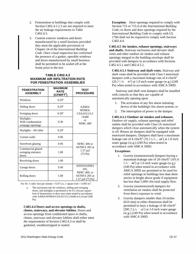
2012 Washington State Energy Code CE-37
2. Fenestration in buildings that comply with
Section C402.4.1.2.3 are not required to meet
the air leakage requirements in Table
C402.4.3.
3. Custom exterior windows and doors
manufactured by a small business provided
they meet the applicable provisions of
Chapter 24 of the International Building
Code. Once visual inspection has confirmed
the presence of a gasket, operable windows
and doors manufactured by small business
shall be permitted to be sealed off at the
frame prior to the test.
TABLE C402.4.3 MAXIMUM AIR INFILTRATION RATE FOR FENESTRATION ASSEMBLIES
FENESTRATION ASSEMBLY
MAXIMUM RATE
(CFM/FT2)
TEST PROCEDURE
Windows 0.20a
AAMA/
WDMA/
CSA101/I.S.2
/A440
or
NFRC 400
Sliding doors 0.20a
Swinging doors 0.20a
Skylights -
With condensation
weepage openings
0.30
Skylights - All other 0.20a
Curtain walls 0.06
NFRC 400 or
ASTM E 283 at
1.57 psf
(75 Pa)
Storefront glazing 0.06
Commercial glazed
swinging entrance
doors
1.00
Revolving doors 1.00
Garage doors 0.40 ANSI/DASMA
105,
NFRC 400, or
ASTM E 283 at
1.57 psf (75 Pa)
Rolling doors 1.00
For SI: 1 cubic foot per minute .= 0.47 L/s, 1 square foot .= 0.093 m2.
a. The maximum rate for windows, sliding and swinging
doors, and skylights is permitted to be 0.3 cfm per square
foot of fenestration or door area when tested in accordance with AAMA/WDMA/CSA101/I.S.2/A440 at 6.24 psf (300
Pa).
C402.4.4 Doors and access openings to shafts,
chutes, stairways, and elevator lobbies. Doors and
access openings from conditioned space to shafts,
chutes, stairways and elevator lobbies shall either meet
the requirements of Section C402.4.3 or shall be
gasketed, weatherstripped or sealed.
Exception: Door openings required to comply with
Section 715 or 715.4 of the International Building
Code; or doors and door openings required by the
International Building Code to comply with UL
1784 shall not be required to comply with Section
C402.4.4.
C402.4.5 Air intakes, exhaust openings, stairways
and shafts. Stairway enclosures and elevator shaft
vents and other outdoor air intakes and exhaust
openings integral to the building envelope shall be
provided with dampers in accordance with Sections
C402.4.5.1 and C402.4.5.2.
C402.4.5.1 Stairway and shaft vents. Stairway and
shaft vents shall be provided with Class I motorized
dampers with a maximum leakage rate of 4 cfm/ft2
(202) at 1.0 inch water gauge (w.g.) (249
Pa) when tested in accordance with AMCA 500D.
Stairway and shaft vent dampers shall be installed
with controls so that they are capable of
automatically opening upon:
1. The activation of any fire alarm initiating
device of the building's fire alarm system; or
2. The interruption of power to the damper.
C402.4.5.2 Outdoor air intakes and exhausts.
Outdoor air supply, exhaust openings and relief
outlets shall be provided with Class IA motorized
dampers which close automatically when the system
is off. Return air dampers shall be equipped with
motorized dampers. Dampers shall have a maximum
leakage rate of 4 cfm/ft2
2) at 1.0 inch
water gauge (w.g.) (249 Pa) when tested in
accordance with AMCA 500D.
Exceptions:
1. Gravity (nonmotorized) dampers having a
maximum leakage rate of 20 cfm/ft2 (101.6
2) at 1.0 inch water gauge (w.g.)
(249 Pa) when tested in accordance with
AMCA 500D are permitted to be used for
relief openings in buildings less than three
stories in height above grade if equipment
has less than 5,000 cfm total supply flow.
2. Gravity (nonmotorized) dampers for
ventilation air intakes shall be protected
from direct exposure to wind.
3. Gravity dampers smaller than 24 inches
(610 mm) in either dimension shall be
permitted to have a leakage of 40 cfm/ft2
2) at 1.0 inch water gauge
(w.g.) (249 Pa) when tested in accordance
with AMCA 500D.
CE-38 2012 Washington State Energy Code
4. Gravity (nonmotorized) dampers in Group
R occupancies where the design outdoor air
intake or exhaust capacity does not exceed
400 cfm (189 L/s).
C402.4.6 Loading dock weatherseals. Cargo doors
and loading dock doors shall be equipped with
weatherseals to restrict infiltration when vehicles are
parked in the doorway.
C402.4.7 Vestibules. All building entrances shall be
protected with an enclosed vestibule, with all doors
opening into and out of the vestibule equipped with
self-closing devices. Vestibules shall be designed so
that in passing through the vestibule it is not necessary
for the interior and exterior doors to open at the same
time. The installation of one or more revolving doors
in the building entrance shall not eliminate the
requirement that a vestibule be provided on any doors
adjacent to revolving doors.
Interior and exterior doors shall have a minimum
distance between them of not less than 7 feet. The
exterior envelope of conditioned vestibules shall
comply with the requirements for a conditioned space.
Either the interior or exterior envelope of
unconditioned vestibules shall comply with the
requirements for a conditioned space. The building
lobby is not considered a vestibule.
Exceptions:
1. Buildings in Climate Zones 1 and 2.
2. Doors not intended to be used by the public,
such as doors to mechanical or electrical
equipment rooms, or intended solely for
employee use.
3. Doors opening directly from a sleeping unit
or dwelling unit.
4. Doors that open directly from a space less
than 3,000 square feet (298 m2) in area and
are separate from the building entrance.
5. Revolving doors.
6. Doors used primarily to facilitate vehicular
movement or material handling and adjacent
personnel doors.
7. Building entrances in buildings that are less
than four stories above grade and less than
10,000 ft2 in area.
8. Elevator doors in parking garages provided
that the elevators have an enclosed lobby at
each level of the garage.
C402.4.8 Recessed lighting. Recessed luminaires
installed in the building thermal envelope shall be
sealed to limit air leakage between conditioned and
unconditioned spaces. All recessed luminaires shall
be IC-rated and labeled as having an air leakage rate of
not more than 2.0 cfm (0.944 L/s) when tested in
accordance with ASTM E 283 at a 1.57 psf (75 Pa)
pressure differential. All recessed luminaires shall be
sealed with a gasket or caulk between the housing and
interior wall or ceiling covering.
C402.5 Walk-in coolers and walk-in freezers. Walk-in
coolers and walk-in freezers shall comply with all of the
following:
1. Shall be equipped with automatic door closers that
firmly close walk-in doors that have been closed
to within 1 inch of full closure.
Exception: Doors wider than 3 feet 9 inches or
taller than 7 feet.
2. Doorways shall have strip doors (curtains),
spring-hinged doors, or other method of
minimizing infiltration when doors are open.
3. Walk-in coolers shall contain wall, ceiling, and
door insulation of at least R-25 and walk-in
freezers at least R-32.
Exception: Glazed portions of doors or structural
members.
4. Walk-in freezers shall contain floor insulation of
at least R-28.
5. Transparent reach-in doors for walk-in freezers
and windows in walk-in freezer doors shall be of
triple-pane glass, either filled with inert gas or
with heat-reflective treated glass.
6. Transparent reach-in doors for walk-in coolers and
windows in walk-in cooler doors shall be
double-pane glass with heat-reflective treated
glass and gas filled; or triple-pane glass, either
filled with inert gas or with heat-reflective treated
glass.
C402.6 Refrigerated warehouse coolers and
refrigerated warehouse freezers. Refrigerated
warehouse coolers and refrigerated warehouse freezers
shall comply with all of the following:
1. Shall be equipped with automatic door closers that
firmly close walk-in doors that have been closed
to within 1 inch of full closure.
Exception: Doors wider than 3 feet 9 inches or
taller than 7 feet.
2. Doorways shall have strip doors (curtains),
spring-hinged doors, or other method of
minimizing infiltration when doors are open.
3. Refrigerated warehouse coolers shall contain
wall, ceiling, and door insulation of at least R-25
and refrigerated warehouse freezers at least R-32.
Exception: Glazed portions of doors or structural
members.
2012 Washington State Energy Code CE-39
4. Refrigerated warehouse freezers shall contain
floor insulation of at least R-28.
5. Transparent reach-in doors for refrigerated
warehouse freezers and windows in refrigerated
warehouse freezer doors shall be of triple-pane
glass, either filled with inert gas or with
heat-reflective treated glass.
6. Transparent reach-in doors for refrigerated
warehouse coolers and windows in refrigerated
warehouse cooler doors shall be double-pane
glass with heat-reflective treated glass and gas
filled; or triple-pane glass, either filled with inert
gas or with heat-reflective treated glass.
SECTION C403 MECHANICAL SYSTEMS
C403.1 General. Mechanical systems and equipment
serving heating, cooling, ventilating, and other needs
shall comply with Section C403.2 (referred to as the
mandatory provisions) and either:
1. Section C403.3 (Simple systems); or
2. Section C403.4 (Complex systems).
Exception: Energy using equipment used by a
manufacturing, industrial or commercial process
other than for conditioning spaces or maintaining
comfort and amenities for the occupants and not
otherwise regulated by C403.2.3, Tables C403.2.1
(1) through (9) inclusive, C403.2.4.5, C403.2.5.4,
C403.2.8, C403.2.13, C403.4.6, C403.5, C403.6,
C404.2, or Table C404.2. Data center HVAC
equipment is not covered by this exception.
Walk-in coolers and walk-in freezers shall comply
with Section C403.5. Refrigerated warehouse coolers
and refrigerated warehouse freezers shall comply with
Section C403.6.
C403.2 Provisions applicable to all mechanical
systems (Mandatory). Mechanical systems and
equipment serving the building heating, cooling or
ventilating needs shall comply with Sections C403.2.1
through C403.2.11.
C403.2.1 Calculation of heating and cooling loads.
Design loads shall be determined in accordance with
the procedures described in ANSI/ASHRAE/ACCA
Standard 183. The design loads shall account for the
building envelope, lighting, ventilation and occupancy
loads based on the project design. Heating and cooling
loads shall be adjusted to account for load reductions
that are achieved where energy recovery systems are
utilized in the HVAC system in accordance with the
ASHRAE HVAC Systems and
Equipment Handbook. Alternatively, design loads shall
be determined by an approved equivalent computation
procedure, using the design parameters specified in
Chapter 3.
C403.2.2 Equipment and system sizing. The output
capacity of heating and cooling equipment and systems
shall not exceed the loads calculated in accordance
with Section C403.2.1. A single piece of equipment
providing both heating and cooling shall satisfy this
provision for one function with the capacity for the
other function as small as possible, within available
equipment options.
Exceptions:
1. Required standby equipment and systems
provided with controls and devices that allow
such systems or equipment to operate
automatically only when the primary
equipment is not operating.
2. Multiple units of the same equipment type
with combined capacities exceeding the
design load and provided with controls that
have the capability to sequence the operation
of each unit based on load.
C403.2.3 HVAC equipment performance
requirements. Equipment shall meet the minimum
efficiency requirements of Tables C403.2.3(1),
C403.2.3(2), C403.2.3(3), C403.2.3(4), C403.2.3(5),
C403.2.3(6), C403.2.3(7) and C403.2.3(8) when tested
and rated in accordance with the applicable test
procedure. Plate-type liquid-to-liquid heat exchangers
shall meet the minimum requirements of Table
C403.2.3(9). The efficiency shall be verified through
certification and listed under an approved certification
program or, if no certification program exists, the
equipment efficiency ratings shall be supported by data
furnished by the manufacturer. Where multiple rating
conditions or performance requirements are provided,
the equipment shall satisfy all stated requirements.
Where components, such as indoor or outdoor coils,
from different manufacturers are used, calculations and
supporting data shall be furnished by the designer that
demonstrates that the combined efficiency of the
specified components meets the requirements herein.
Gas-fired and oil-fired forced air furnaces with input
shall also have an intermittent ignition or interrupted
device (IID), and have either mechanical draft
(including power venting) or a flue damper. A vent
damper is an acceptable alternative to a flue damper
for furnaces where combustion air is drawn from the
225,000 Btu/h (65 kW), including electric furnaces,
CE-40 2012 Washington State Energy Code
that are not located within the conditioned space shall
have jacket losses not exceeding 0.75 percent of the
input rating.
Chilled water plants and buildings with more than
500 tons total capacity shall not have more than 100
tons provided by air-cooled chillers.
Exceptions:
1. Where the designer demonstrates that the
water quality at the building site fails to meet
manufacturer's specifications for the use of
water-cooled equipment.
2. Air-cooled chillers with minimum
efficiencies at least 10 percent higher than
those listed in Table C403.2.3(7).
3. Replacement of existing equipment.
C403.2.3.1 Water-cooled centrifugal chilling
packages. Equipment not designed for operation at
AHRI Standard 550/590 test conditions of 44°F
(7°C) leaving chilled-water temperature and 85°F
(29°C) entering condenser water temperature with 3
shall have maximum full-load kW/ton and NPLV
ratings adjusted using Equations C4-3 and C4-4.
Adjusted minimum full-load COP ratings =
(Full-load COP from Table 6.8.1C of AHRI
Standard 550/590) × Kadj
(Equation C4-3)
Adjusted minimum NPLV rating = (IPLV from
Table 6.8.1C of AHRI Standard 550/590) × Kadj
(Equation C4-4)
Where:
Kadj = A × B
A = 0.0000015318 × (LIFT)4 - 0.000202076
(LIFT)3 .+ 0.0101800 × (LIFT)
2 - 0.2649
58 × LIFT .+ 3.930196
B = 0.0027 × Lvg Evap
(°C) .+ 0.982
LIFT = LvgCond
- LvgEvap
LvgCond
= Full-load condenser leaving water
temperature (°C)
LvgEvap
= Full-load leaving evaporator temperature
(°C)
SI units shall be used in the Kadj equation.
The adjusted full-load and NPLV values shall
only be applicable for centrifugal chillers meeting
all of the following full-load design ranges:
1. The leaving evaporator fluid temperature is
not less than 36°F (2.2°C).
2. The leaving condenser fluid temperature is
not greater than 115°F (46.1°C).
3. LIFT is not less than 20°F (11.1°C) and not
greater than 80°F (44.4°C).
Exception: Centrifugal chillers designed to
operate outside of these ranges need not comply
with this code.
C403.2.3.2 Positive displacement (air- and
water-cooled) chilling packages. Equipment with a
leaving fluid temperature higher than 32°F (0°C),
shall meet the requirements of Table C403.2.3(7)
when tested or certified with water at standard rating
conditions, in accordance with the referenced test
procedure.
C403.2.3.3 Packaged electric heating and cooling
equipment. Packaged electric equipment providing
both heating and cooling with a total cooling
capacity greater than 20,000 Btu/h shall be a heat
pump.
Exception: Unstaffed equipment shelters or
cabinets used solely for personal wireless service
facilities.
C403.2.3.4 Humidification. If an air economizer is
required on a cooling system for which
humidification equipment is to be provided to
maintain minimum indoor humidity levels, then the
humidifier shall be of the adiabatic type (direct
evaporative media or fog atomization type).
Exceptions:
1. Health care facilities where WAC
246-320-525 allows only steam injection
humidifiers in duct work downstream of
final filters.
2. Systems with water economizer.
3. 100% outside air systems with no
provisions for air recirculation to the
central supply fan.
4. Nonadiabatic humidifiers cumulatively
serving no more than 10% of a building's
air economizer capacity as measured in
cfm. This refers to the system cfm serving
rooms with stand alone or duct mounted
humidifiers.
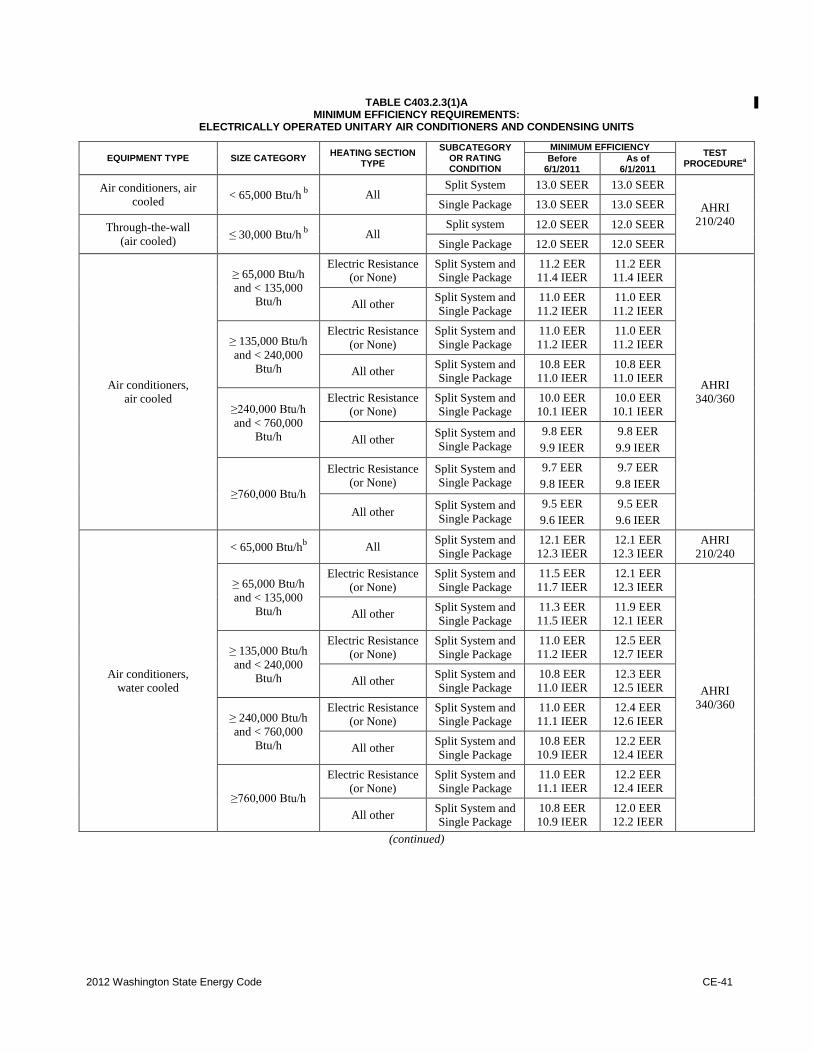
2012 Washington State Energy Code CE-41
TABLE C403.2.3(1)A MINIMUM EFFICIENCY REQUIREMENTS:
ELECTRICALLY OPERATED UNITARY AIR CONDITIONERS AND CONDENSING UNITS
EQUIPMENT TYPE SIZE CATEGORY HEATING SECTION
TYPE
SUBCATEGORY OR RATING CONDITION
MINIMUM EFFICIENCY TEST
PROCEDUREa
Before 6/1/2011
As of 6/1/2011
Air conditioners, air
cooled < 65,000 Btu/h
b All
Split System 13.0 SEER 13.0 SEER
AHRI
210/240
Single Package 13.0 SEER 13.0 SEER
Through-the-wall
(air cooled) ≤30,000 Btu/h
b All
Split system 12.0 SEER 12.0 SEER
Single Package 12.0 SEER 12.0 SEER
Air conditioners,
air cooled
≥65,000 Btu/h
and < 135,000 Btu/h
Electric Resistance (or None)
Split System and Single Package
11.2 EER 11.4 IEER
11.2 EER 11.4 IEER
AHRI
340/360
All other Split System and
Single Package
11.0 EER
11.2 IEER
11.0 EER
11.2 IEER
≥135,000 Btu/h
and < 240,000
Btu/h
Electric Resistance
(or None)
Split System and
Single Package
11.0 EER
11.2 IEER
11.0 EER
11.2 IEER
All other Split System and
Single Package
10.8 EER
11.0 IEER
10.8 EER
11.0 IEER
≥240,000 Btu/h
and < 760,000 Btu/h
Electric Resistance
(or None)
Split System and
Single Package
10.0 EER
10.1 IEER
10.0 EER
10.1 IEER
All other Split System and
Single Package
9.8 EER
9.9 IEER
9.8 EER
9.9 IEER
≥760,000 Btu/h
Electric Resistance
(or None)
Split System and
Single Package
9.7 EER
9.8 IEER
9.7 EER
9.8 IEER
All other Split System and
Single Package
9.5 EER
9.6 IEER
9.5 EER
9.6 IEER
Air conditioners,
water cooled
< 65,000 Btu/hb All
Split System and
Single Package
12.1 EER
12.3 IEER
12.1 EER
12.3 IEER AHRI
210/240
≥65,000 Btu/h
and < 135,000
Btu/h
Electric Resistance
(or None)
Split System and
Single Package
11.5 EER
11.7 IEER
12.1 EER
12.3 IEER
AHRI
340/360
All other Split System and
Single Package
11.3 EER
11.5 IEER
11.9 EER
12.1 IEER
≥135,000 Btu/h
and < 240,000
Btu/h
Electric Resistance
(or None)
Split System and
Single Package
11.0 EER
11.2 IEER
12.5 EER
12.7 IEER
All other Split System and
Single Package
10.8 EER
11.0 IEER
12.3 EER
12.5 IEER
≥240,000 Btu/h
and < 760,000
Btu/h
Electric Resistance
(or None)
Split System and
Single Package
11.0 EER
11.1 IEER
12.4 EER
12.6 IEER
All other Split System and
Single Package
10.8 EER
10.9 IEER
12.2 EER
12.4 IEER
≥760,000 Btu/h
Electric Resistance
(or None)
Split System and
Single Package
11.0 EER
11.1 IEER
12.2 EER
12.4 IEER
All other Split System and
Single Package
10.8 EER
10.9 IEER
12.0 EER
12.2 IEER
(continued)
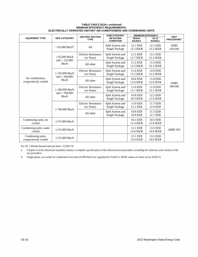
CE-42 2012 Washington State Energy Code
TABLE C403.2.3(1)A—continued
MINIMUM EFFICIENCY REQUIREMENTS: ELECTRICALLY OPERATED UNITARY AIR CONDITIONERS AND CONDENSING UNITS
EQUIPMENT TYPE SIZE CATEGORY HEATING SECTION
TYPE
SUBCATEGORY OR RATING CONDITION
MINIMUM EFFICIENCY TEST
PROCEDUREa
Before 6/1/2011
As of 6/1/2011
Air conditioners,
evaporatively cooled
< 65,000 Btu/hb All
Split System and
Single Package
12.1 EER
12.3 IEER
12.1 EER
12.3 IEER
AHRI
210/240
≥65,000 Btu/h
and < 135,000
Btu/h
Electric Resistance
(or None)
Split System and
Single Package 11.5 EER
11.7 IEER
12.1 EER
12.3 IEER
AHRI
340/360
All other Split System and
Single Package 11.3 EER
11.5 IEER
11.9 EER
12.1 IEER
≥135,000 Btu/h
and < 240,000 Btu/h
Electric Resistance
(or None)
Split System and
Single Package
11.0 EER
11.2 IEER
12.0 EER
12.2 IEER
All other Split System and
Single Package
10.8 EER
11.0 IEER
11.8 EER
12.0 IEER
≥240,000 Btu/h
and < 760,000 Btu/h
Electric Resistance
(or None)
Split System and
Single Package
11.0 EER
11.1 IEER
11.9 EER
12.1 IEER
All other Split System and
Single Package
10.8 EER
10.9 IEER
12.2 EER
11.9 IEER
≥760,000 Btu/h
Electric Resistance
(or None)
Split System and
Single Package
11.0 EER
11.1 EER
11.7 EER
11.9 EER
All other Split System and
Single Package
10.8 EER
10.9 EER
11.5 EER
11.7 EER
Condensing units, air
cooled ≥135,000 Btu/h
10.1 EER
11.4 IEER
10.5 EER
11.8 IEER
AHRI 365 Condensing units, water
cooled ≥135,000 Btu/h
13.1 EER
13.6 IEER
13.5 EER
14.0 IEER
Condensing units,
evaporatively cooled ≥135,000 Btu/h
13.1 EER
13.6 IEER
13.5 EER
14.0 IEER
For SI: 1 British thermal unit per hour = 0.2931 W.
a. Chapter 6 of the referenced standard contains a complete specification of the referenced test procedure, including the reference year version of the
test procedure.
b. Single-phase, air-cooled air conditioners less than 65,000 Btu/h are regulated by NAECA. SEER values are those set by NAECA.
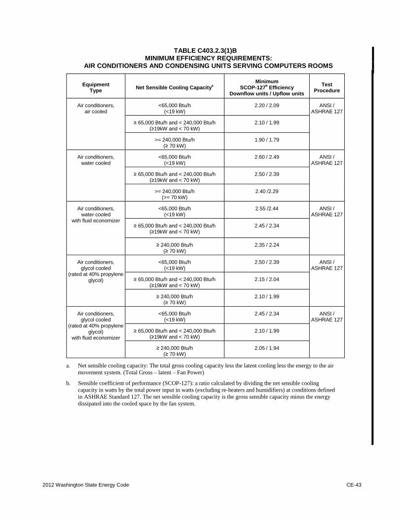
2012 Washington State Energy Code CE-43
TABLE C403.2.3(1)B MINIMUM EFFICIENCY REQUIREMENTS:
AIR CONDITIONERS AND CONDENSING UNITS SERVING COMPUTERS ROOMS
Equipment Type
Net Sensible Cooling Capacitya
Minimum SCOP-127
b Efficiency
Downflow units / Upflow units
Test Procedure
Air conditioners, air cooled
<65,000 Btu/h
(<19 kW) 2.20 / 2.09 ANSI /
ASHRAE 127
≥ 65,000 Btu/h and < 240,000 Btu/h (≥19kW and < 70 kW)
2.10 / 1.99
>= 240,000 Btu/h (≥ 70 kW)
1.90 / 1.79
Air conditioners, water cooled
<65,000 Btu/h (<19 kW)
2.60 / 2.49 ANSI / ASHRAE 127
≥ 65,000 Btu/h and < 240,000 Btu/h (≥19kW and < 70 kW)
2.50 / 2.39
>= 240,000 Btu/h (>= 70 kW)
2.40 /2.29
Air conditioners, water cooled
with fluid economizer
<65,000 Btu/h (<19 kW)
2.55 /2.44 ANSI / ASHRAE 127
≥ 65,000 Btu/h and < 240,000 Btu/h (≥19kW and < 70 kW)
2.45 / 2.34
≥ 240,000 Btu/h (≥ 70 kW)
2.35 / 2.24
Air conditioners, glycol cooled
(rated at 40% propylene glycol)
<65,000 Btu/h (<19 kW)
2.50 / 2.39 ANSI / ASHRAE 127
≥ 65,000 Btu/h and < 240,000 Btu/h (≥19kW and < 70 kW)
2.15 / 2.04
≥ 240,000 Btu/h (≥ 70 kW)
2.10 / 1.99
Air conditioners, glycol cooled
(rated at 40% propylene glycol)
with fluid economizer
<65,000 Btu/h (<19 kW)
2.45 / 2.34 ANSI / ASHRAE 127
≥ 65,000 Btu/h and < 240,000 Btu/h (≥19kW and < 70 kW)
2.10 / 1.99
≥ 240,000 Btu/h (≥ 70 kW)
2.05 / 1.94
a. Net sensible cooling capacity: The total gross cooling capacity less the latent cooling less the energy to the air
movement system. (Total Gross – latent – Fan Power)
b. Sensible coefficient of performance (SCOP-127): a ratio calculated by dividing the net sensible cooling
capacity in watts by the total power input in watts (excluding re-heaters and humidifiers) at conditions defined
in ASHRAE Standard 127. The net sensible cooling capacity is the gross sensible capacity minus the energy
dissipated into the cooled space by the fan system.
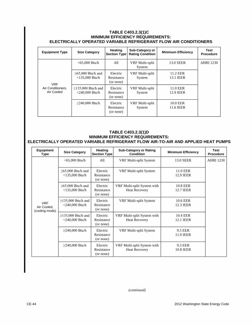
CE-44 2012 Washington State Energy Code
TABLE C403.2.3(1)C MINIMUM EFFICIENCY REQUIREMENTS:
ELECTRICALLY OPERATED VARIABLE REFRIGERANT FLOW AIR CONDITIONERS
Equipment Type Size Category Heating
Section Type Sub-Category or Rating Condition
Minimum Efficiency Test
Procedure
VRF Air Conditioners,
Air Cooled
<65,000 Btu/h All VRF Multi-split
System
13.0 SEER AHRI 1230
≥65,000 Btu/h and
<135,000 Btu/h
Electric
Resistance
(or none)
VRF Multi-split
System
11.2 EER
13.1 IEER
≥135,000 Btu/h and
<240,000 Btu/h
Electric
Resistance
(or none)
VRF Multi-split
System
11.0 EER
12.9 IEER
≥240,000 Btu/h Electric
Resistance
(or none)
VRF Multi-split
System
10.0 EER
11.6 IEER
TABLE C403.2.3(1)D MINIMUM EFFICIENCY REQUIREMENTS:
ELECTRICALLY OPERATED VARIABLE REFRIGERANT FLOW AIR-TO-AIR AND APPLIED HEAT PUMPS
Equipment Type
Size Category Heating
Section Type Sub-Category or Rating
Condition Minimum Efficiency
Test Procedure
VRF Air Cooled,
(cooling mode)
<65,000 Btu/h All
VRF Multi-split System 13.0 SEER AHRI 1230
≥65,000 Btu/h and
<135,000 Btu/h
Electric
Resistance
(or none)
VRF Multi-split System 11.0 EER
12.9 IEER
≥65,000 Btu/h and
<135,000 Btu/h
Electric
Resistance
(or none)
VRF Multi-split System with
Heat Recovery
10.8 EER
12.7 IEER
≥135,000 Btu/h and
<240,000 Btu/h
Electric
Resistance
(or none)
VRF Multi-split System 10.6 EER
12.3 IEER
≥135,000 Btu/h and
<240,000 Btu/h
Electric
Resistance
(or none)
VRF Multi-split System with
Heat Recovery
10.4 EER
12.1 IEER
≥240,000 Btu/h Electric
Resistance
(or none)
VRF Multi-split System 9.5 EER
11.0 IEER
≥240,000 Btu/h Electric
Resistance
(or none)
VRF Multi-split System with
Heat Recovery
9.3 EER
10.8 IEER
(continued)
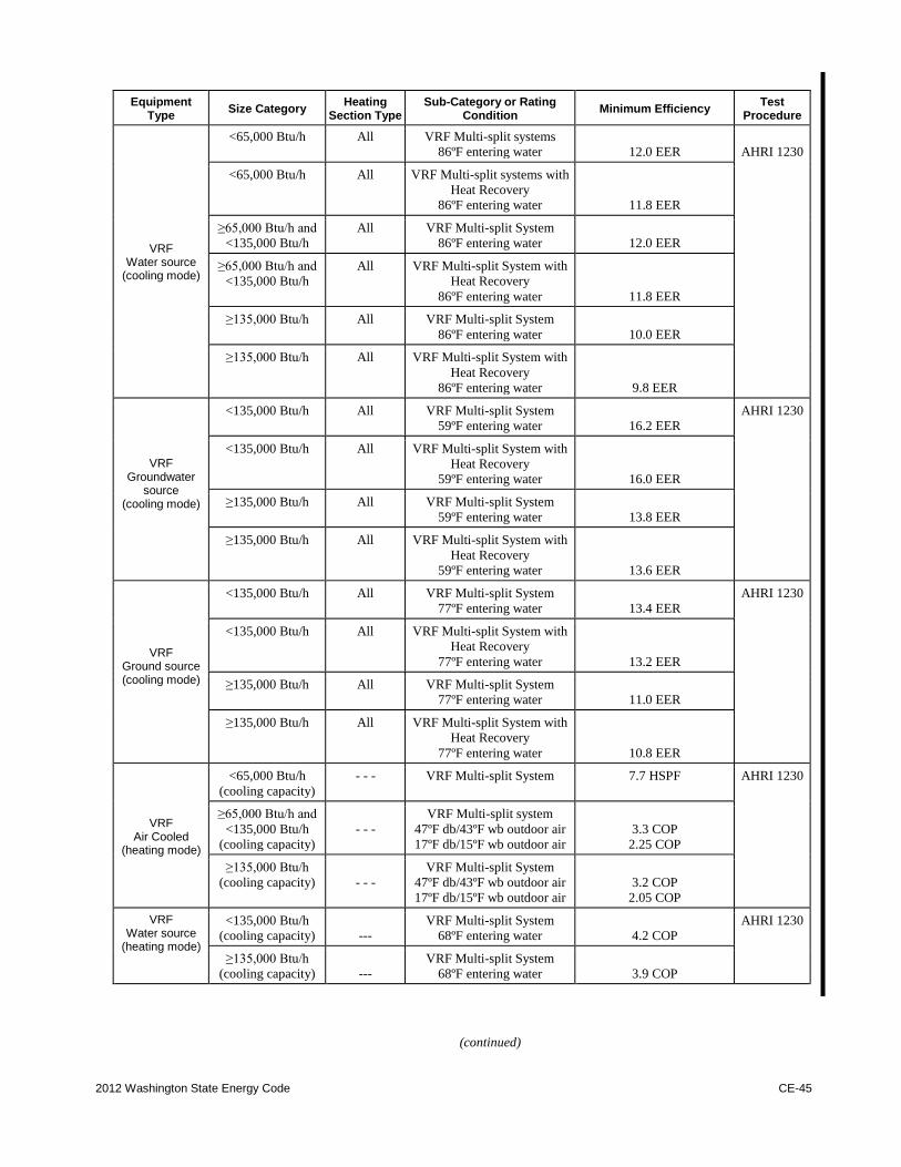
2012 Washington State Energy Code CE-45
Equipment Type
Size Category Heating
Section Type Sub-Category or Rating
Condition Minimum Efficiency
Test Procedure
VRF Water source
(cooling mode)
<65,000 Btu/h All VRF Multi-split systems
86ºF entering water
12.0 EER
AHRI 1230
<65,000 Btu/h All VRF Multi-split systems with
Heat Recovery
86ºF entering water
11.8 EER
≥65,000 Btu/h and
<135,000 Btu/h
All VRF Multi-split System
86ºF entering water
12.0 EER
≥65,000 Btu/h and
<135,000 Btu/h
All VRF Multi-split System with
Heat Recovery
86ºF entering water
11.8 EER
≥135,000 Btu/h All VRF Multi-split System
86ºF entering water
10.0 EER
≥135,000 Btu/h All VRF Multi-split System with
Heat Recovery
86ºF entering water
9.8 EER
VRF Groundwater
source (cooling mode)
<135,000 Btu/h All VRF Multi-split System
59ºF entering water
16.2 EER
AHRI 1230
<135,000 Btu/h All VRF Multi-split System with
Heat Recovery
59ºF entering water
16.0 EER
≥135,000 Btu/h All VRF Multi-split System
59ºF entering water
13.8 EER
≥135,000 Btu/h All VRF Multi-split System with
Heat Recovery
59ºF entering water
13.6 EER
VRF Ground source (cooling mode)
<135,000 Btu/h All VRF Multi-split System
77ºF entering water
13.4 EER
AHRI 1230
<135,000 Btu/h All VRF Multi-split System with
Heat Recovery
77ºF entering water
13.2 EER
≥135,000 Btu/h All VRF Multi-split System
77ºF entering water
11.0 EER
≥135,000 Btu/h All VRF Multi-split System with
Heat Recovery
77ºF entering water
10.8 EER
VRF Air Cooled
(heating mode)
<65,000 Btu/h
(cooling capacity)
- - - VRF Multi-split System 7.7 HSPF AHRI 1230
≥65,000 Btu/h and
<135,000 Btu/h
(cooling capacity)
- - -
VRF Multi-split system
47ºF db/43ºF wb outdoor air
17ºF db/15ºF wb outdoor air
3.3 COP
2.25 COP
≥135,000 Btu/h
(cooling capacity)
- - -
VRF Multi-split System
47ºF db/43ºF wb outdoor air
17ºF db/15ºF wb outdoor air
3.2 COP
2.05 COP
VRF Water source
(heating mode)
<135,000 Btu/h
(cooling capacity)
---
VRF Multi-split System
68ºF entering water
4.2 COP
AHRI 1230
≥135,000 Btu/h
(cooling capacity)
---
VRF Multi-split System
68ºF entering water
3.9 COP
(continued)
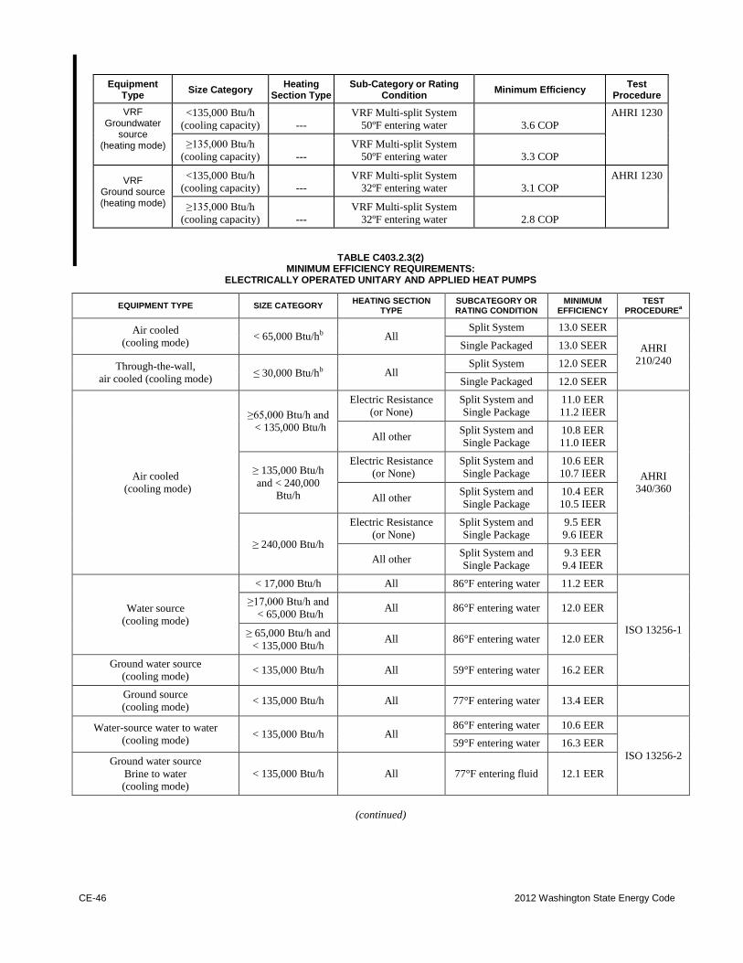
CE-46 2012 Washington State Energy Code
Equipment Type
Size Category Heating
Section Type Sub-Category or Rating
Condition Minimum Efficiency
Test Procedure
VRF Groundwater
source (heating mode)
<135,000 Btu/h
(cooling capacity)
---
VRF Multi-split System
50ºF entering water
3.6 COP
AHRI 1230
≥135,000 Btu/h
(cooling capacity)
---
VRF Multi-split System
50ºF entering water
3.3 COP
VRF Ground source (heating mode)
<135,000 Btu/h
(cooling capacity)
---
VRF Multi-split System
32ºF entering water
3.1 COP
AHRI 1230
≥135,000 Btu/h
(cooling capacity)
---
VRF Multi-split System
32ºF entering water
2.8 COP
TABLE C403.2.3(2) MINIMUM EFFICIENCY REQUIREMENTS:
ELECTRICALLY OPERATED UNITARY AND APPLIED HEAT PUMPS
EQUIPMENT TYPE SIZE CATEGORY HEATING SECTION
TYPE SUBCATEGORY OR RATING CONDITION
MINIMUM EFFICIENCY
TEST PROCEDURE
a
Air cooled
(cooling mode) < 65,000 Btu/hb
All Split System 13.0 SEER
AHRI
210/240
Single Packaged 13.0 SEER
Through-the-wall,
air cooled (cooling mode) ≤30,000 Btu/hb All
Split System 12.0 SEER
Single Packaged 12.0 SEER
Air cooled
(cooling mode)
≥65,000 Btu/h and
< 135,000 Btu/h
Electric Resistance
(or None)
Split System and
Single Package
11.0 EER
11.2 IEER
AHRI
340/360
All other Split System and
Single Package
10.8 EER
11.0 IEER
≥135,000 Btu/h
and < 240,000 Btu/h
Electric Resistance
(or None)
Split System and
Single Package
10.6 EER
10.7 IEER
All other Split System and
Single Package
10.4 EER
10.5 IEER
≥240,000 Btu/h
Electric Resistance
(or None)
Split System and
Single Package
9.5 EER
9.6 IEER
All other Split System and
Single Package
9.3 EER
9.4 IEER
Water source
(cooling mode)
< 17,000 Btu/h All 86°F entering water 11.2 EER
ISO 13256-1
≥17,000 Btu/h and
< 65,000 Btu/h All 86°F entering water 12.0 EER
≥65,000 Btu/h and
< 135,000 Btu/h All 86°F entering water 12.0 EER
Ground water source
(cooling mode) < 135,000 Btu/h All 59°F entering water 16.2 EER
Ground source
(cooling mode) < 135,000 Btu/h All 77°F entering water 13.4 EER
Water-source water to water
(cooling mode) < 135,000 Btu/h All
86°F entering water 10.6 EER
ISO 13256-2
59°F entering water 16.3 EER
Ground water source
Brine to water (cooling mode)
< 135,000 Btu/h All 77°F entering fluid 12.1 EER
(continued)
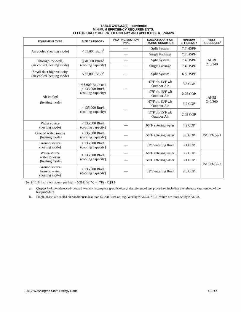
2012 Washington State Energy Code CE-47
TABLE C403.2.3(2)—continued MINIMUM EFFICIENCY REQUIREMENTS:
ELECTRICALLY OPERATED UNITARY AND APPLIED HEAT PUMPS
EQUIPMENT TYPE SIZE CATEGORY HEATING SECTION
TYPE SUBCATEGORY OR RATING CONDITION
MINIMUM EFFICIENCY
TEST PROCEDURE
a
Air cooled (heating mode) < 65,000 Btu/hb — Split System 7.7 HSPF
AHRI
210/240
— Single Package 7.7 HSPF
Through-the-wall,
(air cooled, heating mode)
≤30,000 Btu/hb
(cooling capacity)
— Split System 7.4 HSPF
— Single Package 7.4 HSPF
Small-duct high velocity
(air cooled, heating mode) < 65,000 Btu/hb
— Split System 6.8 HSPF
Air cooled
(heating mode)
≥65,000 Btu/h and
< 135,000 Btu/h (cooling capacity)
—
47ºF db/43ºF wb
Outdoor Air 3.3 COP
AHRI
340/360
17ºF db/15ºF wb
Outdoor Air 2.25 COP
≥135,000 Btu/h (cooling capacity) —
47ºF db/43ºF wb
Outdoor Air 3.2 COP
17ºF db/15ºF wb
Outdoor Air 2.05 COP
Water source
(heating mode)
< 135,000 Btu/h
(cooling capacity) — 68°F entering water 4.2 COP
ISO 13256-1 Ground water source
(heating mode)
< 135,000 Btu/h
(cooling capacity) — 50°F entering water 3.6 COP
Ground source
(heating mode)
< 135,000 Btu/h
(cooling capacity) — 32°F entering fluid 3.1 COP
Water-source
water to water (heating mode)
< 135,000 Btu/h
(cooling capacity)
— 68°F entering water 3.7 COP
ISO 13256-2
— 50°F entering water 3.1 COP
Ground source
brine to water
(heating mode)
< 135,000 Btu/h (cooling capacity)
— 32°F entering fluid 2.5 COP
For SI: 1 British thermal unit per hour = 0.2931 W, °C = [(°F) - 32]/1.8.
a. Chapter 6 of the referenced standard contains a complete specification of the referenced test procedure, including the reference year version of the
test procedure.
b. Single-phase, air-cooled air conditioners less than 65,000 Btu/h are regulated by NAECA. SEER values are those set by NAECA.
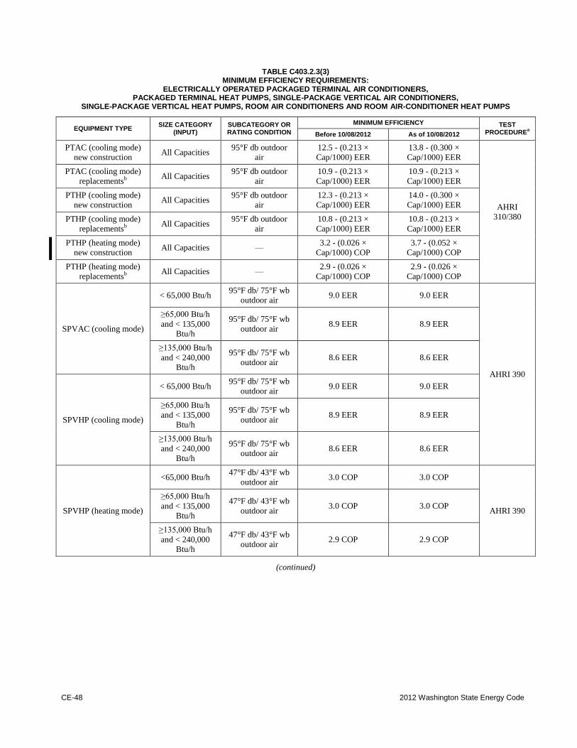
CE-48 2012 Washington State Energy Code
TABLE C403.2.3(3)
MINIMUM EFFICIENCY REQUIREMENTS: ELECTRICALLY OPERATED PACKAGED TERMINAL AIR CONDITIONERS,
PACKAGED TERMINAL HEAT PUMPS, SINGLE-PACKAGE VERTICAL AIR CONDITIONERS, SINGLE-PACKAGE VERTICAL HEAT PUMPS, ROOM AIR CONDITIONERS AND ROOM AIR-CONDITIONER HEAT PUMPS
EQUIPMENT TYPE SIZE CATEGORY
(INPUT) SUBCATEGORY OR RATING CONDITION
MINIMUM EFFICIENCY TEST PROCEDURE
a Before 10/08/2012 As of 10/08/2012
PTAC (cooling mode)
new construction All Capacities
95°F db outdoor
air
12.5 - (0.213 ×
Cap/1000) EER
13.8 - (0.300 ×
Cap/1000) EER
AHRI
310/380
PTAC (cooling mode)
replacementsb
All Capacities 95°F db outdoor
air
10.9 - (0.213 ×
Cap/1000) EER
10.9 - (0.213 ×
Cap/1000) EER
PTHP (cooling mode)
new construction All Capacities
95°F db outdoor
air
12.3 - (0.213 ×
Cap/1000) EER
14.0 - (0.300 ×
Cap/1000) EER
PTHP (cooling mode)
replacementsb
All Capacities 95°F db outdoor
air
10.8 - (0.213 ×
Cap/1000) EER
10.8 - (0.213 ×
Cap/1000) EER
PTHP (heating mode)
new construction All Capacities —
3.2 - (0.026 ×
Cap/1000) COP
3.7 - (0.052 ×
Cap/1000) COP
PTHP (heating mode)
replacementsb
All Capacities — 2.9 - (0.026 ×
Cap/1000) COP
2.9 - (0.026 ×
Cap/1000) COP
SPVAC (cooling mode)
< 65,000 Btu/h 95°F db/ 75°F wb
outdoor air 9.0 EER 9.0 EER
AHRI 390
≥65,000 Btu/h
and < 135,000 Btu/h
95°F db/ 75°F wb
outdoor air 8.9 EER 8.9 EER
≥135,000 Btu/h
and < 240,000 Btu/h
95°F db/ 75°F wb
outdoor air 8.6 EER 8.6 EER
SPVHP (cooling mode)
< 65,000 Btu/h 95°F db/ 75°F wb
outdoor air 9.0 EER 9.0 EER
≥65,000 Btu/h
and < 135,000 Btu/h
95°F db/ 75°F wb
outdoor air 8.9 EER 8.9 EER
≥135,000 Btu/h
and < 240,000
Btu/h
95°F db/ 75°F wb outdoor air
8.6 EER 8.6 EER
SPVHP (heating mode)
<65,000 Btu/h 47°F db/ 43°F wb
outdoor air 3.0 COP 3.0 COP
AHRI 390
≥65,000 Btu/h
and < 135,000 Btu/h
47°F db/ 43°F wb
outdoor air 3.0 COP 3.0 COP
≥135,000 Btu/h
and < 240,000 Btu/h
47°F db/ 43°F wb
outdoor air 2.9 COP 2.9 COP
(continued)
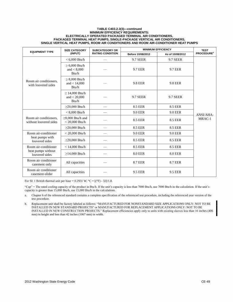
2012 Washington State Energy Code CE-49
TABLE C403.2.3(3)—continued
MINIMUM EFFICIENCY REQUIREMENTS: ELECTRICALLY OPERATED PACKAGED TERMINAL AIR CONDITIONERS,
PACKAGED TERMINAL HEAT PUMPS, SINGLE-PACKAGE VERTICAL AIR CONDITIONERS, SINGLE VERTICAL HEAT PUMPS, ROOM AIR CONDITIONERS AND ROOM AIR-CONDITIONER HEAT PUMPS
EQUIPMENT TYPE SIZE CATEGORY
(INPUT) SUBCATEGORY OR RATING CONDITION
MINIMUM EFFICIENCY TEST PROCEDURE
a Before 10/08/2012 As of 10/08/2012
Room air conditioners,
with louvered sides
< 6,000 Btu/h — 9.7 SEER 9.7 SEER
ANSI/AHA-
MRAC-1
≥6,000 Btu/h
and < 8,000 Btu/h
— 9.7 EER 9.7 EER
≥8,000 Btu/h
and < 14,000 Btu/h
— 9.8 EER 9.8 EER
≥14,000 Btu/h
and < 20,000 Btu/h
— 9.7 SEER 9.7 SEER
≥20,000 Btu/h — 8.5 EER 8.5 EER
Room air conditioners,
without louvered sides
< 8,000 Btu/h — 9.0 EER 9.0 EER
≥8,000 Btu/h and
< 20,000 Btu/h — 8.5 EER 8.5 EER
≥20,000 Btu/h — 8.5 EER 8.5 EER
Room air-conditioner
heat pumps with
louvered sides
< 20,000 Btu/h — 9.0 EER 9.0 EER
≥20,000 Btu/h — 8.5 EER 8.5 EER
Room air-conditioner
heat pumps without louvered sides
< 14,000 Btu/h — 8.5 EER 8.5 EER
≥14,000 Btu/h — 8.0 EER 8.0 EER
Room air conditioner
casement only All capacities — 8.7 EER 8.7 EER
Room air conditioner
casement-slider All capacities — 9.5 EER 9.5 EER
For SI: 1 British thermal unit per hour = 0.2931 W, °C = [(°F) - 32]/1.8.
“Cap” = The rated cooling capacity of the product in Btu/h. If the unit’s capacity is less than 7000 Btu/h, use 7000 Btu/h in the calculation. If the unit’s capacity is greater than 15,000 Btu/h, use 15,000 Btu/h in the calculations.
a. Chapter 6 of the referenced standard contains a complete specification of the referenced test procedure, including the referenced year version of the
test procedure.
b. Replacement unit shall be factory labeled as follows: “MANUFACTURED FOR NONSTANDARD SIZE APPLICATIONS ONLY: NOT TO BE
INSTALLED IN NEW STANDARD PROJECTS” or MANUFACTURED FOR REPLACEMENT APPLICATIONS ONLY: NOT TO BE
INSTALLED IN NEW CONSTRUCTION PROJECTS.” Replacement efficiencies apply only to units with existing sleeves less than 16 inches (406
mm) in height and less than 42 inches (1067 mm) in width.
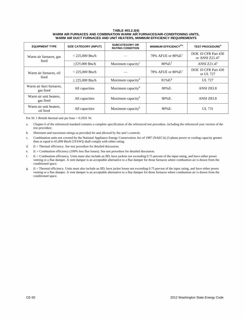
CE-50 2012 Washington State Energy Code
TABLE 403.2.3(4)
WARM AIR FURNACES AND COMBINATION WARM AIR FURNACES/AIR-CONDITIONING UNITS, WARM AIR DUCT FURNACES AND UNIT HEATERS, MINIMUM EFFICIENCY REQUIREMENTS
EQUIPMENT TYPE SIZE CATEGORY (INPUT) SUBCATEGORY OR RATING CONDITION
MINIMUM EFFICIENCYd,e
, TEST PROCEDUREa
Warm air furnaces, gas
fired
< 225,000 Btu/h — 78% AFUE or 80%Etc
DOE 10 CFR Part 430
or ANSI Z21.47
≥225,000 Btu/h Maximum capacityc 80%Et
f ANSI Z21.47
Warm air furnaces, oil
fired
< 225,000 Btu/h — 78% AFUE or 80%Etc DOE 10 CFR Part 430
or UL 727
≥225,000 Btu/h Maximum capacityb 81%Et
g UL 727
Warm air duct furnaces,
gas fired All capacities Maximum capacityb
80%Ec ANSI Z83.8
Warm air unit heaters,
gas fired All capacities Maximum capacityb
80%Ec ANSI Z83.8
Warm air unit heaters,
oil fired All capacities Maximum capacityb
80%Ec UL 731
For SI: 1 British thermal unit per hour = 0.2931 W.
a. Chapter 6 of the referenced standard contains a complete specification of the referenced test procedure, including the referenced year version of the test procedure.
b. Minimum and maximum ratings as provided for and allowed by the unit’s controls.
c. Combination units not covered by the National Appliance Energy Conservation Act of 1987 (NAECA) (3-phase power or cooling capacity greater than or equal to 65,000 Btu/h [19 kW]) shall comply with either rating.
d. Et = Thermal efficiency. See test procedure for detailed discussion.
e. Ec = Combustion efficiency (100% less flue losses). See test procedure for detailed discussion.
f. Ec = Combustion efficiency. Units must also include an IID, have jackets not exceeding 0.75 percent of the input rating, and have either power
venting or a flue damper. A vent damper is an acceptable alternative to a flue damper for those furnaces where combustion air is drawn from the
conditioned space.
g. Et = Thermal efficiency. Units must also include an IID, have jacket losses not exceeding 0.75 percent of the input rating, and have either power
venting or a flue damper. A vent damper is an acceptable alternative to a flue damper for those furnaces where combustion air is drawn from the
conditioned space.
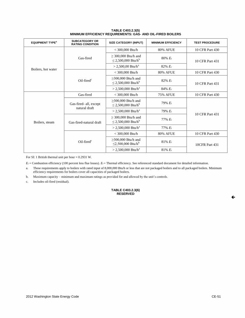
2012 Washington State Energy Code CE-51
TABLE C403.2.3(5)
MINIMUM EFFICIENCY REQUIREMENTS: GAS- AND OIL-FIRED BOILERS
EQUIPMENT TYPEa
SUBCATEGORY OR RATING CONDITION
SIZE CATEGORY (INPUT) MINIMUM EFFICIENCY TEST PROCEDURE
Boilers, hot water
Gas-fired
< 300,000 Btu/h 80% AFUE 10 CFR Part 430
≥300,000 Btu/h and
≤2,500,000 Btu/hb
80% Et
10 CFR Part 431
> 2,500,00 Btu/ha 82% Ec
Oil-firedc
< 300,000 Btu/h 80% AFUE 10 CFR Part 430
≥300,000 Btu/h and
≤2,500,000 Btu/hb
82% Et
10 CFR Part 431
> 2,500,000 Btu/ha 84% Ec
Boilers, steam
Gas-fired < 300,000 Btu/h 75% AFUE 10 CFR Part 430
Gas-fired- all, except
natural draft
≥300,000 Btu/h and
≤2,500,000 Btu/hb
79% Et
10 CFR Part 431 > 2,500,000 Btu/ha
79% Et
Gas-fired-natural draft
≥300,000 Btu/h and
≤2,500,000 Btu/hb
77% Et
> 2,500,000 Btu/ha 77% Et
Oil-firedc
< 300,000 Btu/h 80% AFUE 10 CFR Part 430
≥300,000 Btu/h and
≤2,500,000 Btu/hb
81% Et
10CFR Part 431
> 2,500,000 Btu/ha 81% Et
For SI: 1 British thermal unit per hour = 0.2931 W.
Ec = Combustion efficiency (100 percent less flue losses). Et = Thermal efficiency. See referenced standard document for detailed information.
a. These requirements apply to boilers with rated input of 8,000,000 Btu/h or less that are not packaged boilers and to all packaged boilers. Minimum
efficiency requirements for boilers cover all capacities of packaged boilers.
b. Maximum capacity – minimum and maximum ratings as provided for and allowed by the unit’s controls.
c. Includes oil-fired (residual).
TABLE C403.2.3(6) RESERVED
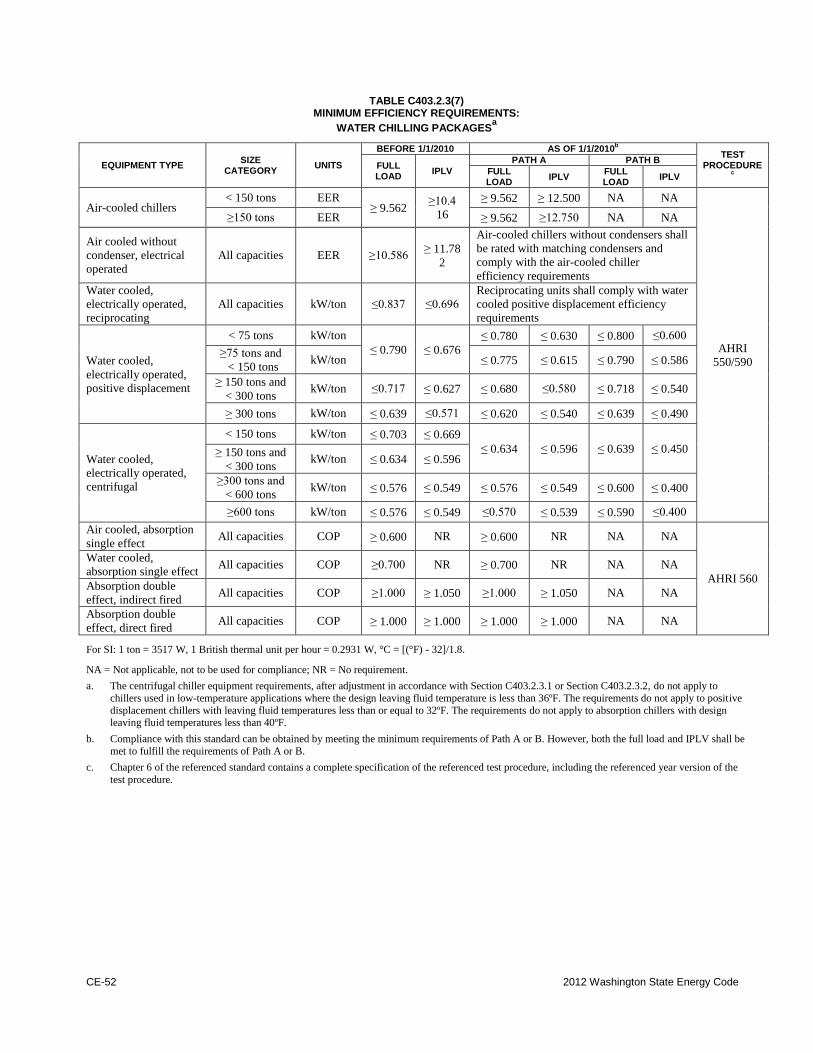
CE-52 2012 Washington State Energy Code
TABLE C403.2.3(7)
MINIMUM EFFICIENCY REQUIREMENTS:
WATER CHILLING PACKAGESa
EQUIPMENT TYPE SIZE
CATEGORY UNITS
BEFORE 1/1/2010 AS OF 1/1/2010b
TEST
PROCEDUREc
FULL LOAD
IPLV
PATH A PATH B
FULL LOAD
IPLV FULL LOAD
IPLV
Air-cooled chillers < 150 tons EER
≥9.562 ≥10.4
16
≥9.562 ≥12.500 NA NA
AHRI
550/590
≥150 tons EER ≥9.562 ≥12.750 NA NA
Air cooled without
condenser, electrical
operated
All capacities EER ≥10.586 ≥11.78
2
Air-cooled chillers without condensers shall
be rated with matching condensers and
comply with the air-cooled chiller
efficiency requirements
Water cooled,
electrically operated,
reciprocating
All capacities kW/ton ≤0.837 ≤0.696
Reciprocating units shall comply with water
cooled positive displacement efficiency
requirements
Water cooled,
electrically operated,
positive displacement
< 75 tons kW/ton
≤0.790 ≤0.676
≤0.780 ≤0.630 ≤0.800 ≤0.600
≥75 tons and
< 150 tons kW/ton ≤0.775 ≤0.615 ≤0.790 ≤0.586
≥150 tons and
< 300 tons kW/ton ≤0.717 ≤0.627 ≤0.680 ≤0.580 ≤0.718 ≤0.540
≥300 tons kW/ton ≤0.639 ≤0.571 ≤0.620 ≤0.540 ≤0.639 ≤0.490
Water cooled,
electrically operated,
centrifugal
< 150 tons kW/ton ≤0.703 ≤0.669
≤0.634 ≤0.596 ≤0.639 ≤0.450 ≥150 tons and
< 300 tons kW/ton ≤0.634 ≤0.596
≥300 tons and
< 600 tons kW/ton ≤0.576 ≤0.549 ≤0.576 ≤0.549 ≤0.600 ≤0.400
≥600 tons kW/ton ≤0.576 ≤0.549 ≤0.570 ≤0.539 ≤0.590 ≤0.400
Air cooled, absorption
single effect All capacities COP ≥0.600 NR ≥0.600 NR NA NA
AHRI 560
Water cooled,
absorption single effect All capacities COP ≥0.700 NR ≥0.700 NR NA NA
Absorption double
effect, indirect fired All capacities COP ≥1.000 ≥1.050 ≥1.000 ≥1.050 NA NA
Absorption double
effect, direct fired All capacities COP ≥1.000 ≥1.000 ≥1.000 ≥1.000 NA NA
For SI: 1 ton = 3517 W, 1 British thermal unit per hour = 0.2931 W, °C = [(°F) - 32]/1.8.
NA = Not applicable, not to be used for compliance; NR = No requirement.
a. The centrifugal chiller equipment requirements, after adjustment in accordance with Section C403.2.3.1 or Section C403.2.3.2, do not apply to
chillers used in low-temperature applications where the design leaving fluid temperature is less than 36ºF. The requirements do not apply to positive
displacement chillers with leaving fluid temperatures less than or equal to 32ºF. The requirements do not apply to absorption chillers with design leaving fluid temperatures less than 40ºF.
b. Compliance with this standard can be obtained by meeting the minimum requirements of Path A or B. However, both the full load and IPLV shall be
met to fulfill the requirements of Path A or B.
c. Chapter 6 of the referenced standard contains a complete specification of the referenced test procedure, including the referenced year version of the
test procedure.
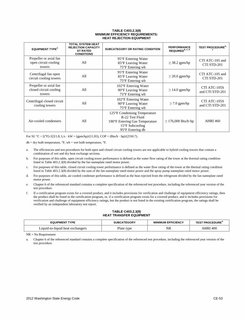
2012 Washington State Energy Code CE-53
TABLE C403.2.3(8)
MINIMUM EFFICIENCY REQUIREMENTS: HEAT REJECTION EQUIPMENT
EQUIPMENT TYPEa
TOTAL SYSTEM HEAT REJECTION CAPACITY
AT RATED CONDITIONS
SUBCATEGORY OR RATING CONDITION PERFORMANCE
REQUIREDb, c, d
TEST PROCEDUREe,
f
Propeller or axial fan
open circuit cooling
towers
All 95°F Entering Water
85°F Leaving Water
75°F Entering wb
≥38.2 gpm/hp CTI ATC-105 and
CTI STD-201
Centrifugal fan open
circuit cooling towers All
95°F Entering Water
85°F Leaving Water
75°F Entering wb
≥20.0 gpm/hp CTI ATC-105 and
CTI STD-201
Propeller or axial fan
closed circuit cooling
towers
All 102°F Entering Water
90°F Leaving Water
75°F Entering wb
≥14.0 gpm/hp CTI ATC-105S
and CTI STD-201
Centrifugal closed circuit
cooling towers All
102°F Entering Water
90°F Leaving Water
75°F Entering wb
≥7.0 gpm/hp CTI ATC-105S
and CTI STD-201
Air-cooled condensers All
125°F Condensing Temperature
R-22 Test Fluid
190°F Entering Gas Temperature
15°F Subcooling
95°F Entering db
≥176,000 Btu/h·hp AHRI 460
For SI: °C = [(°F)-32]/1.8, L/s · kW = (gpm/hp)/(11.83), COP = (Btu/h · hp)/(2550.7).
db = dry bulb temperature, °F, wb = wet bulb temperature, °F.
a. The efficiencies and test procedures for both open and closed circuit cooling towers are not applicable to hybrid cooling towers that contain a
combination of wet and dry heat exchange sections.
b. For purposes of this table, open circuit cooling tower performance is defined as the water flow rating of the tower at the thermal rating condition listed in Table 403.2.3(8) divided by the fan nameplate rated motor power.
c. For purposes of this table, closed circuit cooling tower performance is defined as the water flow rating of the tower at the thermal rating condition
listed in Table 403.2.3(8) divided by the sum of the fan nameplate rated motor power and the spray pump nameplate rated motor power.
d. For purposes of this table, air-cooled condenser performance is defined as the heat rejected from the refrigerant divided by the fan nameplate rated
motor power.
e. Chapter 6 of the referenced standard contains a complete specification of the referenced test procedure, including the referenced year version of the test procedure.
f. If a certification program exists for a covered product, and it includes provisions for verification and challenge of equipment efficiency ratings, then
the product shall be listed in the certification program, or, if a certification program exists for a covered product, and it includes provisions for verification and challenge of equipment efficiency ratings, but the product is not listed in the existing certification program, the ratings shall be
verified by an independent laboratory test report.
TABLE C403.2.3(9)
HEAT TRANSFER EQUIPMENT
EQUIPMENT TYPE SUBCATEGORY MINIMUM EFFICIENCY TEST PROCEDUREa
Liquid-to-liquid heat exchangers Plate type NR AHRI 400
NR = No Requirement
a. Chapter 6 of the referenced standard contains a complete specification of the referenced test procedure, including the referenced year version of the
test procedure.
CE-54 2012 Washington State Energy Code
C403.2.4 HVAC system controls. Each heating and
cooling system shall be provided with thermostatic
controls as specified in Section C403.2.4.1,
C403.2.4.2, C403.2.4.3, C403.2.4.4, C403.4.1,
C403.4.2, C403.4.3, C403.4.4, C403.4.5, C403.4.6,
C403.4.7, C403.4.8, C403.4.9, or C403.4.10.
C403.2.4.1 Thermostatic controls. The supply of
heating and cooling energy to each zone shall be
controlled by individual thermostatic controls
capable of responding to temperature within the
zone. At a minimum, each floor of a building shall
be considered as a separate zone. Controls on
systems required to have economizers and serving
single zones shall have multiple cooling stage
capability and activate the economizer when
appropriate as the first stage of cooling. See Section
C403.3.1 or C403.4.1 for further economizer
requirements. Where humidification or
dehumidification or both is provided, at least one
humidity control device shall be provided for each
humidity control system.
Exception: Independent perimeter systems that
are designed to offset only building envelope heat
losses or gains or both serving one or more
perimeter zones also served by an interior system
provided:
1. The perimeter system includes at least one
thermostatic control zone for each building
exposure having exterior walls facing only
one orientation (within .+/-45 degrees) (0.8
rad) for more than 50 contiguous feet
(15,240 mm); and
2. The perimeter system heating and cooling
supply is controlled by a thermostat located
within the zones served by the system.
C403.2.4.1.1 Heat pump supplementary heat.
Unitary air cooled heat pumps shall include
microprocessor controls that minimize
supplemental heat usage during start-up, set-up,
and defrost conditions. These controls shall
anticipate need for heat and use compression
heating as the first stage of heat. Controls shall
indicate when supplemental heating is being used
through visual means (e.g., LED indicators). Heat
pumps equipped with supplementary heaters shall
be installed with controls that prevent
supplemental heater operation above 40°F.
Exception: Packaged terminal heat pumps
(PTHPs) of less than 2 tons (24,000 Btu/hr)
cooling capacity provided with controls that
prevent supplementary heater operation above
40°F.
C403.2.4.2 Setpoint overlap restriction. Where
used to control both heating and cooling, zone
thermostatic controls shall provide a temperature
range or deadband of at least 5°F (2.8°C) within
which the supply of heating and cooling energy to
the zone is capable of being shut off or reduced to a
minimum.
Exception: Thermostats requiring manual
changeover between heating and cooling modes.
C403.2.4.3 Off-hour controls. For all occupancies
other than Group R, each zone shall be provided
with thermostatic setback controls that are controlled
by either an automatic time clock or programmable
control system.
Exceptions:
1. Zones that will be operated continuously.
2. Zones with a full HVAC load demand not
exceeding 6,800 Btu/h (2 kW) and having a
readily accessible manual shutoff switch.
C403.2.4.3.1 Thermostatic setback capabilities.
Thermostatic setback controls shall have the
capability to set back or temporarily operate the
system to maintain zone temperatures down to
55°F (13°C) or up to 85°F (29°C).
C403.2.4.3.2 Automatic setback and shutdown
capabilities. Automatic time clock or
programmable controls shall be capable of starting
and stopping the system for seven different daily
schedules per week and retaining their
programming and time setting during a loss of
power for at least 10 hours. Additionally, the
controls shall have a manual override that allows
temporary operation of the system for up to 2
hours; a manually operated timer capable of being
adjusted to operate the system for up to 2 hours; or
an occupancy sensor.
C403.2.4.3.3 Automatic start capabilities.
Automatic start controls shall be provided for each
HVAC system. The controls shall be capable of
automatically adjusting the daily start time of the
HVAC system in order to bring each space to the
desired occupied temperature immediately prior to
scheduled occupancy.
C403.2.4.4 Shutoff damper controls. Both outdoor
air supply and exhaust ducts shall be equipped with
motorized dampers that will automatically shut
when the systems or spaces served are not in use or
during building warm-up, cooldown, and setback.
2012 Washington State Energy Code CE-55
Exceptions:
1. Gravity relief dampers serving systems less
than 5,000 cfm total supply shall be
permitted in buildings less than three
stories in height.
2. Gravity dampers shall be permitted for
buildings of any height located in Climate
Zones 1, 2 and 3.
3. Gravity (nonmotorized) dampers in Group
R occupancies where the design outdoor air
intake or exhaust capacity does not exceed
400 cfm (189 L/s).
4. Systems serving areas which require
continuous operation.
5. Combustion air intakes.
6. Operation of dampers shall be allowed
during ventilation prepurge one hour before
expected occupancy and for unoccupied
period precooling during the cooling
season.
7. Dampers are not required in systems where
specifically prohibited by the International
Mechanical Code.
C403.2.4.5 Snow melt system controls. Snow- and
ice-melting systems, supplied through energy
service to the building, shall include automatic
controls capable of shutting off the system when the
pavement temperature is above 50°F (10°C) and no
precipitation is falling and an automatic or manual
control that will allow shutoff when the outdoor
temperature is above 40°F (4°C) so that the potential
for snow or ice accumulation is negligible.
C403.2.4.6 Combustion heating equipment
controls. Combustion heating equipment with a
capacity over 225,000 Btu/h shall have modulating
or staged combustion control.
Exceptions:
1. Boilers.
2. Radiant heaters.
C403.2.4.7 Group R-1 hotel/motel guest rooms.
For hotel and motel guest rooms, a minimum of one
of the following control technologies shall be
required in hotels/motels with over 50 guest rooms
such that the space temperature would automatically
setback (winter) or set up (summer) by no less than
5°F (3°C) or hotel and motel guest rooms, a
minimum of:
1. Controls that are activated by the room
occupant via the primary room access
method - Key, card, deadbolt, etc.
2. Occupancy sensor controls that are activated
by the occupant's presence in the room.
C403.2.4.8 Group R-2 and R-3 dwelling units.
The primary space conditioning system within each
dwelling unit shall be provided with at least one
programmable thermostat for the regulation of space
temperature. The thermostat shall allow for, at a
minimum, a 5-2 programmable schedule
(weekdays/weekends) and be capable of providing at
least two programmable setback periods per day.
Each additional system provided within the
dwelling unit shall be provided with at least one
adjustable thermostat for the regulation of
temperature.
Exceptions:
1. Systems controlled by an occupant sensor
that is capable of shutting the system off
when no occupant is sensed for a period of
up to 30 minutes.
2. Systems controlled solely by a manually
operated timer capable of operating the
system for no more than two hours.
3. Ductless heat pumps.
Each thermostat shall be capable of being set by
adjustment or selection of sensors as follows:
When used to control heating only: 55°F to 75°F;
when used to control cooling only: 70°F to 85°F;
all other: 55°F to 85°F with an adjustable deadband
of not less than10°F.
C403.2.4.9 Group R-2 sleeping units. The primary
space conditioning system within each sleeping unit
shall be provided with at least one programmable
thermostat for the regulation of space temperature.
The thermostat shall allow for, at a minimum, a 5-2
programmable schedule (weekdays/weekends) and
be capable of providing at least two programmable
setback periods per day.
Each additional system provided within the
sleeping unit shall be provided with at least one
adjustable thermostat for the regulation of
temperature.
Exceptions:
1. Systems controlled by an occupant sensor
that is capable of shutting the system off
when no occupant is sensed for a period of
up to 30 minutes.
2. Systems controlled solely by a manually
operated timer capable of operating the
system for no more than two hours.
CE-56 2012 Washington State Energy Code
3. Zones with a full HVAC load demand not
exceeding 3,400 Btu/h (1 kW) and having a
readily accessible manual shutoff switch.
4. Ductless heat pumps.
Each thermostat shall be capable of being set by
adjustment or selection of sensors as follows:
When used to control heating only: 55°F to 75°F;
when used to control cooling only: 70°F to 85°F;
all other: 55°F to 85°F with an adjustable deadband
of not less than10°F.
C403.2.4.10 Direct digital control system
capabilities. All complex systems equipped with
direct digital control (DDC) systems and all
buildings with total cooling capacity exceeding
780,000 Btu/h (2,662 kW) shall have the following
capability:
1. Trending: All control system input and
output points shall be accessible and
programmed for trending, and a graphic
trending package shall be provided with the
control system.
2. Demand Response Setpoint Adjustment:
Control logic shall increase the cooling zone
set points by at least 2°F (1°C) and reduce the
heating zone set points by at least 2°F (1°C)
when activated by a demand response signal.
The demand response signal shall be a binary
input to the control system or other interface
approved by the serving electric utility.
C403.2.5 Ventilation. Ventilation, either natural or
mechanical, shall be provided in accordance with
Chapter 4 of the International Mechanical Code.
Where mechanical ventilation is provided, the system
shall provide the capability to reduce the outdoor air
supply to the minimum required by Chapter 4 of the
International Mechanical Code.
C403.2.5.1 Demand controlled ventilation.
Demand control ventilation (DCV) shall be provided
for spaces larger than 500 square feet (50 m2) and
with an occupant load greater than 25 people per
1000 square feet (93 m2) of floor area (as established
in Table 403.3 of the International Mechanical
Code) and served by systems with one or more of
the following:
1. An air-side economizer;
2. Automatic modulating control of the outdoor
air damper; or
3. A design outdoor airflow greater than 3,000
cfm (1400 L/s).
Exception: Demand control ventilation is not
required for systems and spaces as follows:
1. Systems with energy recovery complying
with Section C403.2.6.
2. Multiple-zone systems without direct
digital control of individual zones
communicating with a central control
panel.
3. System with a design outdoor airflow
less than 1,000 cfm (472 L/s).
4. Spaces where the supply airflow rate
minus any makeup or outgoing transfer
air requirement is less than 1,200 cfm
(600 L/s).
5. Ventilation provided for process loads
only.
C403.2.5.2 Occupancy sensors. Classrooms, gyms,
auditoriums and conference rooms larger than 500
square feet of floor area shall have occupancy sensor
control that will either close outside air dampers or
turn off serving equipment when the space is
unoccupied except where equipped with another
means to automatically reduce outside air intake
below design rates when spaces are partially
occupied.
C403.2.5.3 Enclosed loading dock and parking
garage exhaust ventilation system control.
Mechanical ventilation systems for enclosed loading
docks and parking garages shall be designed to
exhaust the airflow rates (maximum and minimum)
determined in accordance with the International
Mechanical Code.
Ventilation systems shall be equipped with a
control device that operates the system automatically
upon detection of vehicle operation or the presence
of occupants by approved automatic detection
devices. Each of the following types of controllers
shall be capable of shutting off fans or modulating
fan speed. Control devices shall not reduce airflow
rates below the minimum requirement in accordance
with the International Mechanical Code during
scheduled periods of occupied operation.
1. Gas sensor controllers used to activate the
exhaust ventilation system shall stage or
modulate fan speed upon detection of
specified gas levels. All equipment used in
sensor controlled systems shall be designed
for the specific use and installed in
accordance with the manufacturer's
recommendations. The system shall be
arranged to operate automatically by means
of carbon monoxide detectors applied in
conjunction with nitrogen dioxide detectors.
Garages and loading docks shall be equipped
2012 Washington State Energy Code CE-57
with a controller and a full array of carbon
monoxide (CO) sensors set to maintain levels
of carbon monoxide below 35 parts per
million (ppm). Additionally, a full array of
nitrogen dioxide detectors shall be connected
to the controller set to maintain the nitrogen
dioxide level below the OSHA standard for
eight hour exposure. Spacing and location of
the sensors shall be installed in accordance
with manufacturer recommendations.
2. Occupant detection sensors used to activate
the system shall detect entry into the parking
garage along both the vehicle and pedestrian
pathways.
C403.2.5.3.1 System activation devices for
enclosed loading docks. Ventilation systems for
enclosed loading docks shall be activated by one
of the following:
1. Gas sensors installed in accordance with
the International Mechanical Code; or
2. Occupant detection sensors used to activate
the system that detects entry into the
loading area along both the vehicle and
pedestrian pathways.
C403.2.5.3.2 System activation devices for
enclosed parking garages. Ventilation systems
for enclosed parking garages shall be activated by
gas sensors.
Exception: A parking garage ventilation
system having a total design capacity under
8,000 cfm may use occupant sensors.
C403.2.5.4 Exhaust systems.
C403.2.5.4.1 Kitchen hoods. Each kitchen area
with total exhaust capacity larger than 2,000 cfm
shall be provided with make-up air sized so that at
least 50% of exhaust air volume be (a) unheated
or heated to no more than 60°F and (b) uncooled
or cooled without the use of mechanical cooling.
Exceptions:
1. Where hoods are used to exhaust
ventilation air which would otherwise
exfiltrate or be exhausted by other fan
systems. A detailed accounting of
exhaust airflows shall be provided on the
plans that accounts for the impact of any
required demand controlled ventilation.
2. Certified grease extractor hoods that
require a face velocity no greater than 60
fpm.
C403.2.5.4.2 Laboratory exhaust systems.
Buildings with laboratory exhaust systems having
a total exhaust rate greater than 5,000 cfm (2,360
L/s) shall include heat recovery systems to
preconditioned makeup air from laboratory
exhaust. The heat recovery system shall be
capable of increasing the outside air supply
temperature at design heating conditions by 25°F
(13.9°C) in Climate Zones 4C/5B and 35°F
(19.4°C) in Climate Zone 6B. A provision shall be
made to bypass or control the heat recovery
system to permit air economizer operation as
required by Section C403.4.
Exceptions:
1. Variable air volume laboratory exhaust
and room supply systems capable of
reducing exhaust and make-up air
volume to 50% or less of design values;
or
2. Direct make-up (auxiliary) air supply
equal to at least 75% of the exhaust rate,
heated no warmer than 2°F (1.1°C)
below room set point, cooled to no cooler
than 3°F (1.7°C) above room set point,
no humidification added, and no
simultaneous heating and cooling used
for dehumidification control; or
3. Combined Energy Reduction Method:
VAV exhaust and room supply system
capable of reducing exhaust and makeup
air volumes and a heat recovery system
to precondition makeup air from
laboratory exhaust that when combined
will produce the same energy reduction
as achieved by a heat recovery system
with a 50% sensible recovery
effectiveness as required above. For
calculation purposes, the heat recovery
component can be assumed to include the
maximum design supply airflow rate at
design conditions. The combined energy
reduction (QER) shall meet the following:
QER ≥ QMIN
QMIN = CFMS · (TR • TO) · 1.1 · 0.6
QER = CFMS · (TR • TO)
· 1.1(A+B)/100
Where:
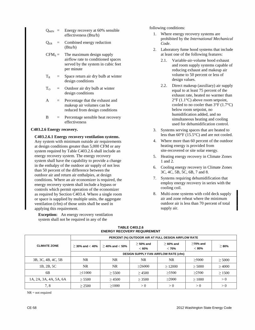
CE-58 2012 Washington State Energy Code
QMIN = Energy recovery at 60% sensible
effectiveness (Btu/h)
QER = Combined energy reduction
(Btu/h)
CFMS = The maximum design supply
airflow rate to conditioned spaces
served by the system in cubic feet
per minute
TR = Space return air dry bulb at winter
design conditions
TO = Outdoor air dry bulb at winter
design conditions
A = Percentage that the exhaust and
makeup air volumes can be
reduced from design conditions
B = Percentage sensible heat recovery
effectiveness
C403.2.6 Energy recovery.
C403.2.6.1 Energy recovery ventilation systems.
Any system with minimum outside air requirements
at design conditions greater than 5,000 CFM or any
system required by Table C403.2.6 shall include an
energy recovery system. The energy recovery
system shall have the capability to provide a change
in the enthalpy of the outdoor air supply of not less
than 50 percent of the difference between the
outdoor air and return air enthalpies, at design
conditions. Where an air economizer is required, the
energy recovery system shall include a bypass or
controls which permit operation of the economizer
as required by Section C403.4. Where a single room
or space is supplied by multiple units, the aggregate
ventilation (cfm) of those units shall be used in
applying this requirement.
Exception: An energy recovery ventilation
system shall not be required in any of the
following conditions:
1. Where energy recovery systems are
prohibited by the International Mechanical
Code.
2. Laboratory fume hood systems that include
at least one of the following features:
2.1. Variable-air-volume hood exhaust
and room supply systems capable of
reducing exhaust and makeup air
volume to 50 percent or less of
design values.
2.2. Direct makeup (auxiliary) air supply
equal to at least 75 percent of the
exhaust rate, heated no warmer than
2°F (1.1°C) above room setpoint,
cooled to no cooler than 3°F (1.7°C)
below room setpoint, no
humidification added, and no
simultaneous heating and cooling
used for dehumidification control.
3. Systems serving spaces that are heated to
less than 60°F (15.5°C) and are not cooled.
4. Where more than 60 percent of the outdoor
heating energy is provided from
site-recovered or site solar energy.
5. Heating energy recovery in Climate Zones
1 and 2.
6. Cooling energy recovery in Climate Zones
3C, 4C, 5B, 5C, 6B, 7 and 8.
7. Systems requiring dehumidification that
employ energy recovery in series with the
cooling coil.
8. Multi-zone systems with cold deck supply
air and zone reheat where the minimum
outdoor air is less than 70 percent of total
supply air.
TABLE C403.2.6
ENERGY RECOVERY REQUIREMENT
CLIMATE ZONE
PERCENT (%) OUTDOOR AIR AT FULL DESIGN AIRFLOW RATE
≥30% and 40% ≥40% and 50% ≥50% and
60%
≥60% and
70%
≥70% and
80% ≥80%
DESIGN SUPPLY FAN AIRFLOW RATE (cfm)
3B, 3C, 4B, 4C, 5B NR NR NR NR ≥5000 ≥5000
1B, 2B, 5C NR NR ≥26000 ≥12000 ≥5000 ≥4000
6B ≥11000 ≥5500 ≥4500 ≥3500 ≥2500 ≥1500
1A, 2A, 3A, 4A, 5A, 6A ≥5500 ≥4500 ≥3500 ≥2000 ≥1000 > 0
7, 8 ≥2500 ≥1000 > 0 > 0 > 0 > 0
NR = not required
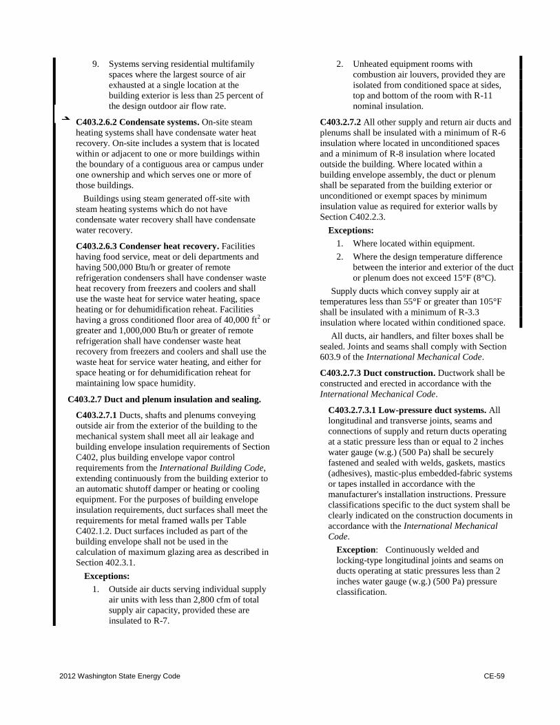
2012 Washington State Energy Code CE-59
9. Systems serving residential multifamily
spaces where the largest source of air
exhausted at a single location at the
building exterior is less than 25 percent of
the design outdoor air flow rate.
C403.2.6.2 Condensate systems. On-site steam
heating systems shall have condensate water heat
recovery. On-site includes a system that is located
within or adjacent to one or more buildings within
the boundary of a contiguous area or campus under
one ownership and which serves one or more of
those buildings.
Buildings using steam generated off-site with
steam heating systems which do not have
condensate water recovery shall have condensate
water recovery.
C403.2.6.3 Condenser heat recovery. Facilities
having food service, meat or deli departments and
having 500,000 Btu/h or greater of remote
refrigeration condensers shall have condenser waste
heat recovery from freezers and coolers and shall
use the waste heat for service water heating, space
heating or for dehumidification reheat. Facilities
having a gross conditioned floor area of 40,000 ft2 or
greater and 1,000,000 Btu/h or greater of remote
refrigeration shall have condenser waste heat
recovery from freezers and coolers and shall use the
waste heat for service water heating, and either for
space heating or for dehumidification reheat for
maintaining low space humidity.
C403.2.7 Duct and plenum insulation and sealing.
C403.2.7.1 Ducts, shafts and plenums conveying
outside air from the exterior of the building to the
mechanical system shall meet all air leakage and
building envelope insulation requirements of Section
C402, plus building envelope vapor control
requirements from the International Building Code,
extending continuously from the building exterior to
an automatic shutoff damper or heating or cooling
equipment. For the purposes of building envelope
insulation requirements, duct surfaces shall meet the
requirements for metal framed walls per Table
C402.1.2. Duct surfaces included as part of the
building envelope shall not be used in the
calculation of maximum glazing area as described in
Section 402.3.1.
Exceptions:
1. Outside air ducts serving individual supply
air units with less than 2,800 cfm of total
supply air capacity, provided these are
insulated to R-7.
2. Unheated equipment rooms with
combustion air louvers, provided they are
isolated from conditioned space at sides,
top and bottom of the room with R-11
nominal insulation.
C403.2.7.2 All other supply and return air ducts and
plenums shall be insulated with a minimum of R-6
insulation where located in unconditioned spaces
and a minimum of R-8 insulation where located
outside the building. Where located within a
building envelope assembly, the duct or plenum
shall be separated from the building exterior or
unconditioned or exempt spaces by minimum
insulation value as required for exterior walls by
Section C402.2.3.
Exceptions:
1. Where located within equipment.
2. Where the design temperature difference
between the interior and exterior of the duct
or plenum does not exceed 15°F (8°C).
Supply ducts which convey supply air at
temperatures less than 55°F or greater than 105°F
shall be insulated with a minimum of R-3.3
insulation where located within conditioned space.
All ducts, air handlers, and filter boxes shall be
sealed. Joints and seams shall comply with Section
603.9 of the International Mechanical Code.
C403.2.7.3 Duct construction. Ductwork shall be
constructed and erected in accordance with the
International Mechanical Code.
C403.2.7.3.1 Low-pressure duct systems. All
longitudinal and transverse joints, seams and
connections of supply and return ducts operating
at a static pressure less than or equal to 2 inches
water gauge (w.g.) (500 Pa) shall be securely
fastened and sealed with welds, gaskets, mastics
(adhesives), mastic-plus embedded-fabric systems
or tapes installed in accordance with the
manufacturer's installation instructions. Pressure
classifications specific to the duct system shall be
clearly indicated on the construction documents in
accordance with the International Mechanical
Code.
Exception: Continuously welded and
locking-type longitudinal joints and seams on
ducts operating at static pressures less than 2
inches water gauge (w.g.) (500 Pa) pressure
classification.
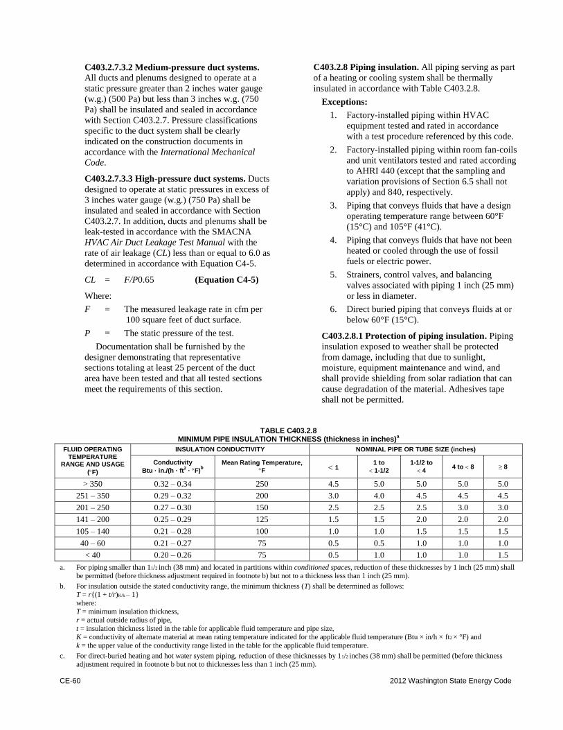
CE-60 2012 Washington State Energy Code
C403.2.7.3.2 Medium-pressure duct systems.
All ducts and plenums designed to operate at a
static pressure greater than 2 inches water gauge
(w.g.) (500 Pa) but less than 3 inches w.g. (750
Pa) shall be insulated and sealed in accordance
with Section C403.2.7. Pressure classifications
specific to the duct system shall be clearly
indicated on the construction documents in
accordance with the International Mechanical
Code.
C403.2.7.3.3 High-pressure duct systems. Ducts
designed to operate at static pressures in excess of
3 inches water gauge (w.g.) (750 Pa) shall be
insulated and sealed in accordance with Section
C403.2.7. In addition, ducts and plenums shall be
leak-tested in accordance with the SMACNA
HVAC Air Duct Leakage Test Manual with the
rate of air leakage (CL) less than or equal to 6.0 as
determined in accordance with Equation C4-5.
CL = F/P0.65 (Equation C4-5)
Where:
F = The measured leakage rate in cfm per
100 square feet of duct surface.
P = The static pressure of the test.
Documentation shall be furnished by the
designer demonstrating that representative
sections totaling at least 25 percent of the duct
area have been tested and that all tested sections
meet the requirements of this section.
C403.2.8 Piping insulation. All piping serving as part
of a heating or cooling system shall be thermally
insulated in accordance with Table C403.2.8.
Exceptions:
1. Factory-installed piping within HVAC
equipment tested and rated in accordance
with a test procedure referenced by this code.
2. Factory-installed piping within room fan-coils
and unit ventilators tested and rated according
to AHRI 440 (except that the sampling and
variation provisions of Section 6.5 shall not
apply) and 840, respectively.
3. Piping that conveys fluids that have a design
operating temperature range between 60°F
(15°C) and 105°F (41°C).
4. Piping that conveys fluids that have not been
heated or cooled through the use of fossil
fuels or electric power.
5. Strainers, control valves, and balancing
valves associated with piping 1 inch (25 mm)
or less in diameter.
6. Direct buried piping that conveys fluids at or
below 60°F (15°C).
C403.2.8.1 Protection of piping insulation. Piping
insulation exposed to weather shall be protected
from damage, including that due to sunlight,
moisture, equipment maintenance and wind, and
shall provide shielding from solar radiation that can
cause degradation of the material. Adhesives tape
shall not be permitted.
TABLE C403.2.8 MINIMUM PIPE INSULATION THICKNESS (thickness in inches)
a
FLUID OPERATING TEMPERATURE
RANGE AND USAGE
(F)
INSULATION CONDUCTIVITY NOMINAL PIPE OR TUBE SIZE (inches)
Conductivity
Btu · in./(h · ft2 · F)
b
Mean Rating Temperature,
F 1 1 to
1-1/2
1-1/2 to
4 4 to 8 ≥8
> 350 0.32 – 0.34 250 4.5 5.0 5.0 5.0 5.0
251 – 350 0.29 – 0.32 200 3.0 4.0 4.5 4.5 4.5
201 – 250 0.27 – 0.30 150 2.5 2.5 2.5 3.0 3.0
141 – 200 0.25 – 0.29 125 1.5 1.5 2.0 2.0 2.0
105 – 140 0.21 – 0.28 100 1.0 1.0 1.5 1.5 1.5
40 – 60 0.21 – 0.27 75 0.5 0.5 1.0 1.0 1.0
< 40 0.20 – 0.26 75 0.5 1.0 1.0 1.0 1.5
a. For piping smaller than 11/2 inch (38 mm) and located in partitions within conditioned spaces, reduction of these thicknesses by 1 inch (25 mm) shall be permitted (before thickness adjustment required in footnote b) but not to a thickness less than 1 inch (25 mm).
b. For insulation outside the stated conductivity range, the minimum thickness (T) shall be determined as follows: T = r{(1 + t/r)K/k – 1}
where: T = minimum insulation thickness,
r = actual outside radius of pipe,
t = insulation thickness listed in the table for applicable fluid temperature and pipe size, K = conductivity of alternate material at mean rating temperature indicated for the applicable fluid temperature (Btu × in/h × ft2 × °F) and
k = the upper value of the conductivity range listed in the table for the applicable fluid temperature.
c. For direct-buried heating and hot water system piping, reduction of these thicknesses by 11/2 inches (38 mm) shall be permitted (before thickness adjustment required in footnote b but not to thicknesses less than 1 inch (25 mm).
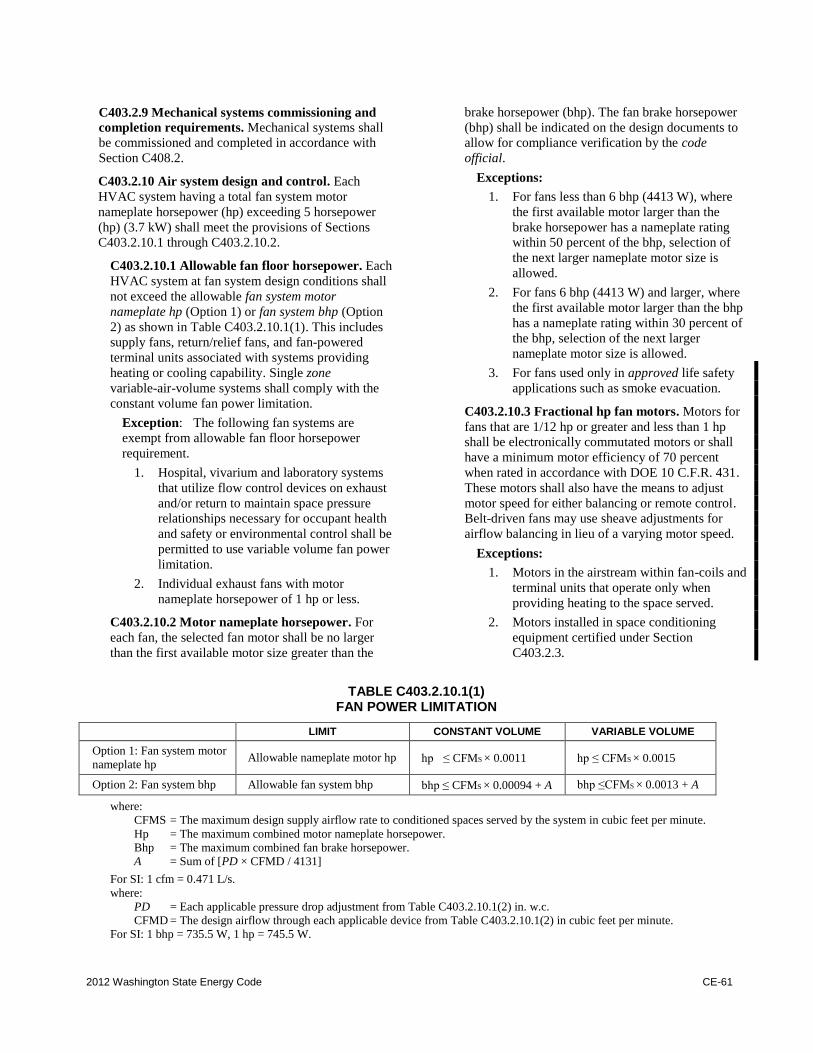
2012 Washington State Energy Code CE-61
C403.2.9 Mechanical systems commissioning and
completion requirements. Mechanical systems shall
be commissioned and completed in accordance with
Section C408.2.
C403.2.10 Air system design and control. Each
HVAC system having a total fan system motor
nameplate horsepower (hp) exceeding 5 horsepower
(hp) (3.7 kW) shall meet the provisions of Sections
C403.2.10.1 through C403.2.10.2.
C403.2.10.1 Allowable fan floor horsepower. Each
HVAC system at fan system design conditions shall
not exceed the allowable fan system motor
nameplate hp (Option 1) or fan system bhp (Option
2) as shown in Table C403.2.10.1(1). This includes
supply fans, return/relief fans, and fan-powered
terminal units associated with systems providing
heating or cooling capability. Single zone
variable-air-volume systems shall comply with the
constant volume fan power limitation.
Exception: The following fan systems are
exempt from allowable fan floor horsepower
requirement.
1. Hospital, vivarium and laboratory systems
that utilize flow control devices on exhaust
and/or return to maintain space pressure
relationships necessary for occupant health
and safety or environmental control shall be
permitted to use variable volume fan power
limitation.
2. Individual exhaust fans with motor
nameplate horsepower of 1 hp or less.
C403.2.10.2 Motor nameplate horsepower. For
each fan, the selected fan motor shall be no larger
than the first available motor size greater than the
brake horsepower (bhp). The fan brake horsepower
(bhp) shall be indicated on the design documents to
allow for compliance verification by the code
official.
Exceptions:
1. For fans less than 6 bhp (4413 W), where
the first available motor larger than the
brake horsepower has a nameplate rating
within 50 percent of the bhp, selection of
the next larger nameplate motor size is
allowed.
2. For fans 6 bhp (4413 W) and larger, where
the first available motor larger than the bhp
has a nameplate rating within 30 percent of
the bhp, selection of the next larger
nameplate motor size is allowed.
3. For fans used only in approved life safety
applications such as smoke evacuation.
C403.2.10.3 Fractional hp fan motors. Motors for
fans that are 1/12 hp or greater and less than 1 hp
shall be electronically commutated motors or shall
have a minimum motor efficiency of 70 percent
when rated in accordance with DOE 10 C.F.R. 431.
These motors shall also have the means to adjust
motor speed for either balancing or remote control.
Belt-driven fans may use sheave adjustments for
airflow balancing in lieu of a varying motor speed.
Exceptions:
1. Motors in the airstream within fan-coils and
terminal units that operate only when
providing heating to the space served.
2. Motors installed in space conditioning
equipment certified under Section
C403.2.3.
TABLE C403.2.10.1(1) FAN POWER LIMITATION
LIMIT CONSTANT VOLUME VARIABLE VOLUME
Option 1: Fan system motor
nameplate hp Allowable nameplate motor hp hp ≤CFMS × 0.0011 hp ≤CFMS × 0.0015
Option 2: Fan system bhp Allowable fan system bhp bhp ≤CFMS × 0.00094 + A bhp ≤CFMS × 0.0013 + A
where:
CFMS = The maximum design supply airflow rate to conditioned spaces served by the system in cubic feet per minute.
Hp = The maximum combined motor nameplate horsepower.
Bhp = The maximum combined fan brake horsepower.
A = Sum of [PD × CFMD / 4131]
For SI: 1 cfm = 0.471 L/s.
where:
PD = Each applicable pressure drop adjustment from Table C403.2.10.1(2) in. w.c.
CFMD = The design airflow through each applicable device from Table C403.2.10.1(2) in cubic feet per minute.
For SI: 1 bhp = 735.5 W, 1 hp = 745.5 W.
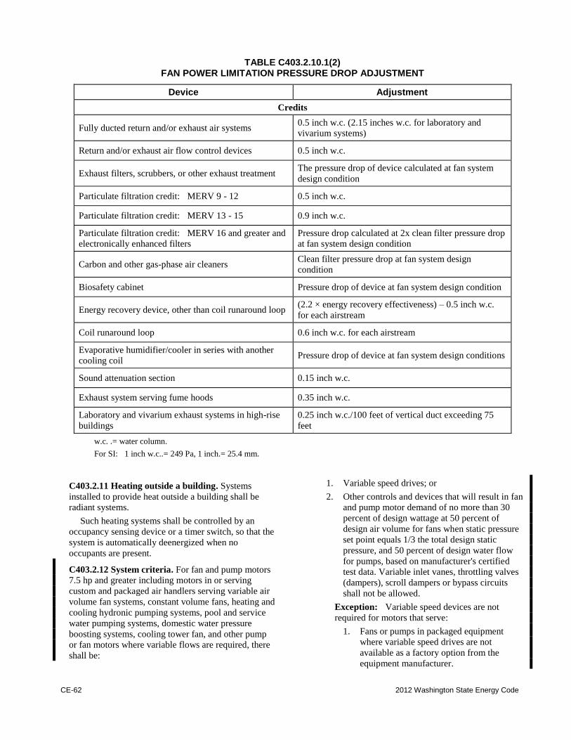
CE-62 2012 Washington State Energy Code
TABLE C403.2.10.1(2) FAN POWER LIMITATION PRESSURE DROP ADJUSTMENT
Device Adjustment
Credits
Fully ducted return and/or exhaust air systems 0.5 inch w.c. (2.15 inches w.c. for laboratory and
vivarium systems)
Return and/or exhaust air flow control devices 0.5 inch w.c.
Exhaust filters, scrubbers, or other exhaust treatment The pressure drop of device calculated at fan system
design condition
Particulate filtration credit: MERV 9 - 12 0.5 inch w.c.
Particulate filtration credit: MERV 13 - 15 0.9 inch w.c.
Particulate filtration credit: MERV 16 and greater and
electronically enhanced filters Pressure drop calculated at 2x clean filter pressure drop
at fan system design condition
Carbon and other gas-phase air cleaners Clean filter pressure drop at fan system design
condition
Biosafety cabinet Pressure drop of device at fan system design condition
Energy recovery device, other than coil runaround loop (2.2 × energy recovery effectiveness) – 0.5 inch w.c.
for each airstream
Coil runaround loop 0.6 inch w.c. for each airstream
Evaporative humidifier/cooler in series with another
cooling coil Pressure drop of device at fan system design conditions
Sound attenuation section 0.15 inch w.c.
Exhaust system serving fume hoods 0.35 inch w.c.
Laboratory and vivarium exhaust systems in high-rise
buildings 0.25 inch w.c./100 feet of vertical duct exceeding 75
feet
w.c. .= water column.
For SI: 1 inch w.c..= 249 Pa, 1 inch.= 25.4 mm.
C403.2.11 Heating outside a building. Systems
installed to provide heat outside a building shall be
radiant systems.
Such heating systems shall be controlled by an
occupancy sensing device or a timer switch, so that the
system is automatically deenergized when no
occupants are present.
C403.2.12 System criteria. For fan and pump motors
7.5 hp and greater including motors in or serving
custom and packaged air handlers serving variable air
volume fan systems, constant volume fans, heating and
cooling hydronic pumping systems, pool and service
water pumping systems, domestic water pressure
boosting systems, cooling tower fan, and other pump
or fan motors where variable flows are required, there
shall be:
1. Variable speed drives; or
2. Other controls and devices that will result in fan
and pump motor demand of no more than 30
percent of design wattage at 50 percent of
design air volume for fans when static pressure
set point equals 1/3 the total design static
pressure, and 50 percent of design water flow
for pumps, based on manufacturer's certified
test data. Variable inlet vanes, throttling valves
(dampers), scroll dampers or bypass circuits
shall not be allowed.
Exception: Variable speed devices are not
required for motors that serve:
1. Fans or pumps in packaged equipment
where variable speed drives are not
available as a factory option from the
equipment manufacturer.
2012 Washington State Energy Code CE-63
2. Fans or pumps that are required to operate
only for emergency fire-life-safety events
(e.g., stairwell pressurization fans, elevator
pressurization fans, fire pumps, etc.).
C403.2.12.1 Heat rejection equipment. The
requirements of this section apply to heat rejection
equipment used in comfort cooling systems such as
air-cooled condensers, open cooling towers,
closed-circuit cooling towers, and evaporative
condensers.
Exception: Heat rejection devices included as an
integral part of equipment listed in Tables
C403.2.3(1) through C403.2.3(3).
Heat rejection equipment shall have a minimum
efficiency performance not less than values specified
in Table C403.2.3(8). These requirements apply to
all propeller, axial fan and centrifugal fan cooling
towers. Table C403.2.3(8) specifies requirements for
air-cooled condensers that are within rating
conditions specified within the table.
C403.2.12.1.1 Variable flow controls. Cooling
tower fans 7.5 hp and greater shall have control
devices that vary flow by controlling the leaving
fluid temperature or condenser
temperature/pressure of the heat rejection device.
C403.2.12.1.2 Limitation on centrifugal fan
cooling towers. Open cooling towers with a
combined rated capacity of 1,100 gpm and greater
at 95°F condenser water return, 85°F condenser
water supply and 75°F outdoor wet-bulb
temperature shall meet the energy efficiency
requirement for axial fan open circuit cooling
towers.
Exception: Open circuit cooling towers that
are ducted (inlet or discharge) or have external
sound attenuation that requires external static
pressure capability.
C403.2.12.2 Large volume fan systems. Single or
multiple fan systems serving a zone or adjacent
zones without separating walls with total air flow
over 10,000 cfm (3,540 L/s) are required to reduce
airflow based on space thermostat heating and
cooling demand. A variable speed drive shall reduce
airflow to a maximum 75 percent of peak airflow or
minimum ventilation air requirement as required by
Section 403 of the International Mechanical Code,
whichever is greater.
Exceptions:
1. Systems where the function of the supply
air is for purposes other than temperature
control, such as maintaining specific
humidity levels or supplying an exhaust
system.
2. Dedicated outdoor air supply unit(s) with
heat recovery where airflow is equal to
the minimum ventilation requirements
and other fans cycle off unless heating or
cooling is required.
3. An area served by multiple units where
designated ventilation units have 50
percent or less of total area airflow and
nonventilation unit fans cycle off when
heating or cooling is not required.
All air-conditioning equipment and air-handling
units with direct expansion cooling and a cooling
capacity at AHRI conditions greater than or equal to
110,000 Btu/h that serve single zones shall have
their supply fans controlled by two-speed motors or
variable speed drives. At cooling demands less than
or equal to 50 percent, the supply fan controls shall
be able to reduce the airflow to no greater than the
larger of the following:
1. Two-thirds of the full fan speed; or
2. The volume of outdoor air required to meet
the ventilation requirements of Section 403 of
the International Mechanical Code.
C403.2.13 Electric motor efficiency. Design A and B
squirrel-cage, T-frame induction permanently wired
polyphase motors of 1 hp or more having synchronous
speeds of 3,600, 1,800 and 1,200 rpm shall have a
nominal full-load motor efficiency no less than the
corresponding values for energy efficient motors
provided in NEMA Standard MG-1.
Exceptions:
1. Motors used in systems designed to use more
than one speed of a multi-speed motor.
2. Motors used as a component of the equipment
meeting the minimum equipment efficiency
requirements of Section C403.2.3 and Tables
C403.2.3(1) through C403.2.3(9) provided
that the motor input is included when
determining the equipment efficiency.
3. Motors that are an integral part of specialized
process equipment.
4. Where the motor is integral to a listed piece
of equipment for which no complying motor
has been approved.
Fan motors less than 1 hp in series terminal units
shall be electronically commutated motors, or shall
have a minimum motor efficiency of 65 percent when
rated in accordance with NEMA Standard MG-1 at full
load rating conditions.
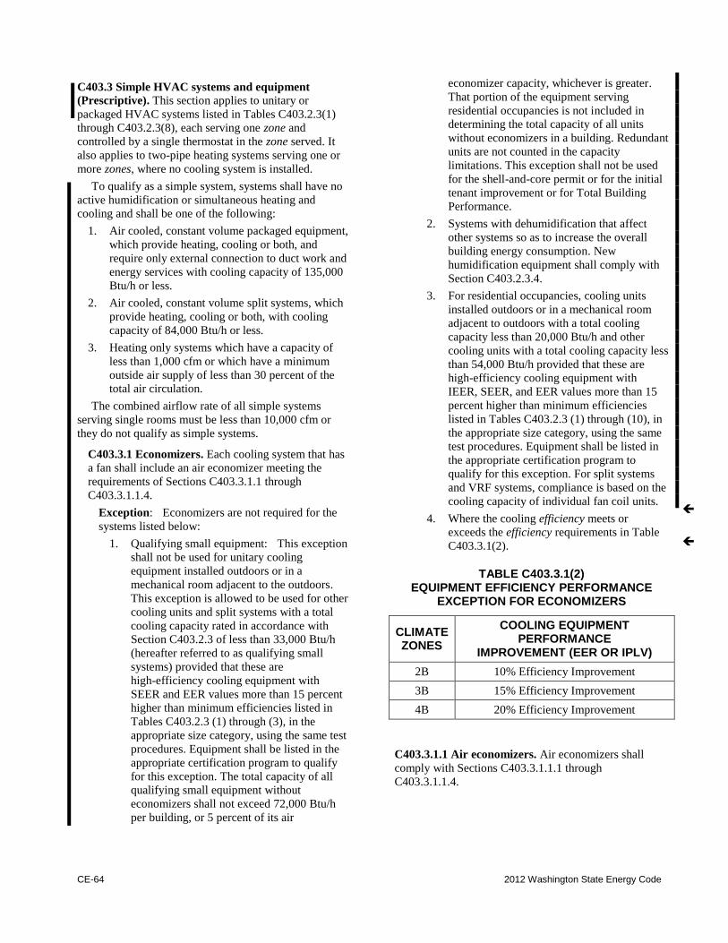
CE-64 2012 Washington State Energy Code
C403.3 Simple HVAC systems and equipment
(Prescriptive). This section applies to unitary or
packaged HVAC systems listed in Tables C403.2.3(1)
through C403.2.3(8), each serving one zone and
controlled by a single thermostat in the zone served. It
also applies to two-pipe heating systems serving one or
more zones, where no cooling system is installed.
To qualify as a simple system, systems shall have no
active humidification or simultaneous heating and
cooling and shall be one of the following:
1. Air cooled, constant volume packaged equipment,
which provide heating, cooling or both, and
require only external connection to duct work and
energy services with cooling capacity of 135,000
Btu/h or less.
2. Air cooled, constant volume split systems, which
provide heating, cooling or both, with cooling
capacity of 84,000 Btu/h or less.
3. Heating only systems which have a capacity of
less than 1,000 cfm or which have a minimum
outside air supply of less than 30 percent of the
total air circulation.
The combined airflow rate of all simple systems
serving single rooms must be less than 10,000 cfm or
they do not qualify as simple systems.
C403.3.1 Economizers. Each cooling system that has
a fan shall include an air economizer meeting the
requirements of Sections C403.3.1.1 through
C403.3.1.1.4.
Exception: Economizers are not required for the
systems listed below:
1. Qualifying small equipment: This exception
shall not be used for unitary cooling
equipment installed outdoors or in a
mechanical room adjacent to the outdoors.
This exception is allowed to be used for other
cooling units and split systems with a total
cooling capacity rated in accordance with
Section C403.2.3 of less than 33,000 Btu/h
(hereafter referred to as qualifying small
systems) provided that these are
high-efficiency cooling equipment with
SEER and EER values more than 15 percent
higher than minimum efficiencies listed in
Tables C403.2.3 (1) through (3), in the
appropriate size category, using the same test
procedures. Equipment shall be listed in the
appropriate certification program to qualify
for this exception. The total capacity of all
qualifying small equipment without
economizers shall not exceed 72,000 Btu/h
per building, or 5 percent of its air
economizer capacity, whichever is greater.
That portion of the equipment serving
residential occupancies is not included in
determining the total capacity of all units
without economizers in a building. Redundant
units are not counted in the capacity
limitations. This exception shall not be used
for the shell-and-core permit or for the initial
tenant improvement or for Total Building
Performance.
2. Systems with dehumidification that affect
other systems so as to increase the overall
building energy consumption. New
humidification equipment shall comply with
Section C403.2.3.4.
3. For residential occupancies, cooling units
installed outdoors or in a mechanical room
adjacent to outdoors with a total cooling
capacity less than 20,000 Btu/h and other
cooling units with a total cooling capacity less
than 54,000 Btu/h provided that these are
high-efficiency cooling equipment with
IEER, SEER, and EER values more than 15
percent higher than minimum efficiencies
listed in Tables C403.2.3 (1) through (10), in
the appropriate size category, using the same
test procedures. Equipment shall be listed in
the appropriate certification program to
qualify for this exception. For split systems
and VRF systems, compliance is based on the
cooling capacity of individual fan coil units.
4. Where the cooling efficiency meets or
exceeds the efficiency requirements in Table
C403.3.1(2).
TABLE C403.3.1(2) EQUIPMENT EFFICIENCY PERFORMANCE
EXCEPTION FOR ECONOMIZERS
CLIMATE ZONES
COOLING EQUIPMENT PERFORMANCE
IMPROVEMENT (EER OR IPLV)
2B 10% Efficiency Improvement
3B 15% Efficiency Improvement
4B 20% Efficiency Improvement
C403.3.1.1 Air economizers. Air economizers shall
comply with Sections C403.3.1.1.1 through
C403.3.1.1.4.
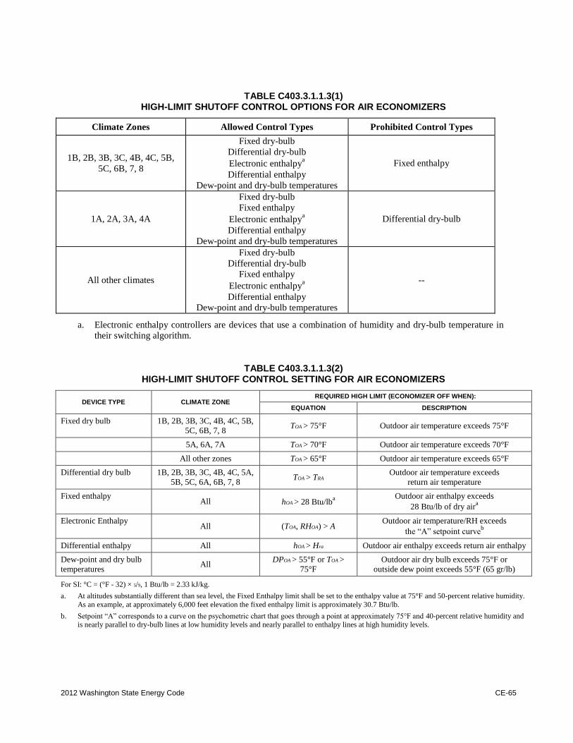
2012 Washington State Energy Code CE-65
TABLE C403.3.1.1.3(1) HIGH-LIMIT SHUTOFF CONTROL OPTIONS FOR AIR ECONOMIZERS
Climate Zones Allowed Control Types Prohibited Control Types
1B, 2B, 3B, 3C, 4B, 4C, 5B,
5C, 6B, 7, 8
Fixed dry-bulb
Differential dry-bulb
Electronic enthalpya
Differential enthalpy
Dew-point and dry-bulb temperatures
Fixed enthalpy
1A, 2A, 3A, 4A
Fixed dry-bulb
Fixed enthalpy
Electronic enthalpya
Differential enthalpy
Dew-point and dry-bulb temperatures
Differential dry-bulb
All other climates
Fixed dry-bulb
Differential dry-bulb
Fixed enthalpy
Electronic enthalpya
Differential enthalpy
Dew-point and dry-bulb temperatures
--
a. Electronic enthalpy controllers are devices that use a combination of humidity and dry-bulb temperature in
their switching algorithm.
TABLE C403.3.1.1.3(2) HIGH-LIMIT SHUTOFF CONTROL SETTING FOR AIR ECONOMIZERS
DEVICE TYPE CLIMATE ZONE REQUIRED HIGH LIMIT (ECONOMIZER OFF WHEN):
EQUATION DESCRIPTION
Fixed dry bulb 1B, 2B, 3B, 3C, 4B, 4C, 5B,
5C, 6B, 7, 8 TOA > 75°F Outdoor air temperature exceeds 75°F
5A, 6A, 7A TOA > 70°F Outdoor air temperature exceeds 70°F
All other zones TOA > 65°F Outdoor air temperature exceeds 65°F
Differential dry bulb 1B, 2B, 3B, 3C, 4B, 4C, 5A,
5B, 5C, 6A, 6B, 7, 8 TOA > TRA
Outdoor air temperature exceeds
return air temperature
Fixed enthalpy All hOA > 28 Btu/lb
a
Outdoor air enthalpy exceeds
28 Btu/lb of dry aira
Electronic Enthalpy All (TOA, RHOA) > A
Outdoor air temperature/RH exceeds
the “A” setpoint curveb
Differential enthalpy All hOA > Hra Outdoor air enthalpy exceeds return air enthalpy
Dew-point and dry bulb
temperatures All
DPOA > 55°F or TOA >
75°F
Outdoor air dry bulb exceeds 75°F or
outside dew point exceeds 55°F (65 gr/lb)
For SI: °C = (°F - 32) × 5/9, 1 Btu/lb = 2.33 kJ/kg.
a. At altitudes substantially different than sea level, the Fixed Enthalpy limit shall be set to the enthalpy value at 75°F and 50-percent relative humidity.
As an example, at approximately 6,000 feet elevation the fixed enthalpy limit is approximately 30.7 Btu/lb.
b. Setpoint “A” corresponds to a curve on the psychometric chart that goes through a point at approximately 75°F and 40-percent relative humidity and is nearly parallel to dry-bulb lines at low humidity levels and nearly parallel to enthalpy lines at high humidity levels.
CE-66 2012 Washington State Energy Code
C403.3.1.1.1 Design capacity. Air economizer
systems shall be capable of modulating outdoor
air and return air dampers to provide up to 100
percent of the design supply air quantity as
outdoor air for cooling.
C403.3.1.1.2 Control signal. Economizer
dampers shall be capable of being sequenced with
the mechanical cooling equipment and shall not be
controlled by only mixed air temperature. Air
economizers on systems with cooling capacity
greater than 65,000 Btu/h shall be capable of
providing partial cooling even when additional
mechanical cooling is required to meet the
remainder of the cooling load.
Exception: The use of mixed air temperature
limit control shall be permitted for systems that
are both controlled from space temperature
(such as single zone systems) and having
cooling capacity less than 65,000 Btu/h.
C403.3.1.1.3 High-limit shutoff. Air economizers
shall be capable of automatically reducing outdoor
air intake to the design minimum outdoor air
quantity when outdoor air intake will no longer
reduce cooling energy usage. High-limit shutoff
control types for specific climates shall be chosen
from Table C403.3.1.1.3(1). High-limit shutoff
control settings for these control types shall be
those specified in Table C403.3.1.1.3(2).
C403.3.1.1.4 Relief of excess outdoor air.
Systems shall be capable of relieving excess
outdoor air during air economizer operation to
prevent over-pressurizing the building. The relief
air outlet shall be located to avoid recirculation
into the building.
C403.3.2 Hydronic system controls. Hydronic
systems of at least 300,000 Btu/h (87,930 W) design
output capacity supplying heated and chilled water to
comfort conditioning systems shall include controls
that meet the requirements of Section C403.4.3.
C403.4 Complex HVAC systems and equipment
(prescriptive). This section applies to HVAC equipment
and systems not covered in Section C403.3.
For buildings with a total equipment cooling capacity
of 300 tons and above, the equipment shall comply with
one of the following:
1. No one unit shall have a cooling capacity of more
than 2/3 of the total installed cooling equipment
capacity;
2. The equipment shall have a variable speed drive;
or
3. The equipment shall have multiple compressors.
C403.4.1 Economizers. Air economizers shall be
provided on all new systems including those serving
computer server rooms, electronic equipment, radio
equipment, and telephone switchgear. Economizers
shall comply with Sections C403.4.1.1 through
C403.4.1.4.
Exceptions:
1. Water-cooled refrigeration equipment serving
chilled beams and chilled ceiling space
cooling systems only which are provided with
a water economizer meeting the requirements
of Section C403.4.1. Water economizer
capacity per building shall not exceed 500
tons. This exception shall not be used for
Total Building Performance.
2. Systems complying with all of the following
criteria:
2.1. Consist of multiple water source heat
pumps connected to a common water
loop;
2.2. Have a minimum of 60 percent air
economizer;
2.3. Have water source heat pumps with an
EER at least 15 percent higher for
cooling and a COP at least 15 percent
higher for heating than that specified in
Section C403.2.3;
2.4. Where provided, have a central boiler or
furnace efficiency of 90 percent
minimum for units up to 199,000 Btu/h;
and
2.5. Provide heat recovery with a minimum
50 percent heat recovery effectiveness
as defined in Section C403.2.6 to
preheat the outside air supply.
3. Chilled water terminal units connected to
systems with chilled water generation
equipment with IPLV values more than 25
percent higher than minimum part load
efficiencies listed in Table C403.2.3(7), in the
appropriate size category, using the same test
procedures. Equipment shall be listed in the
appropriate certification program to qualify
for this exception. The total capacity of all
systems without economizers shall not exceed
480,000 Btu/h per building, or 20 percent of
its air economizer capacity, whichever is
greater. That portion of the equipment serving
Group R Occupancy is not included in
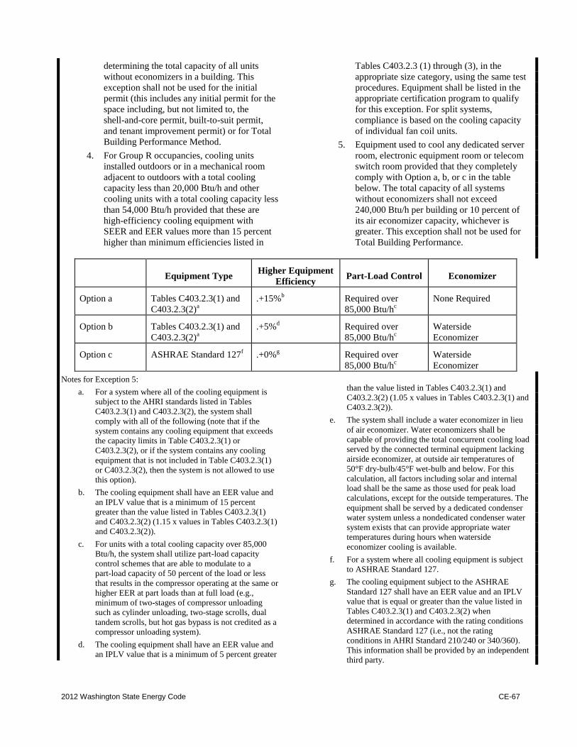
2012 Washington State Energy Code CE-67
determining the total capacity of all units
without economizers in a building. This
exception shall not be used for the initial
permit (this includes any initial permit for the
space including, but not limited to, the
shell-and-core permit, built-to-suit permit,
and tenant improvement permit) or for Total
Building Performance Method.
4. For Group R occupancies, cooling units
installed outdoors or in a mechanical room
adjacent to outdoors with a total cooling
capacity less than 20,000 Btu/h and other
cooling units with a total cooling capacity less
than 54,000 Btu/h provided that these are
high-efficiency cooling equipment with
SEER and EER values more than 15 percent
higher than minimum efficiencies listed in
Tables C403.2.3 (1) through (3), in the
appropriate size category, using the same test
procedures. Equipment shall be listed in the
appropriate certification program to qualify
for this exception. For split systems,
compliance is based on the cooling capacity
of individual fan coil units.
5. Equipment used to cool any dedicated server
room, electronic equipment room or telecom
switch room provided that they completely
comply with Option a, b, or c in the table
below. The total capacity of all systems
without economizers shall not exceed
240,000 Btu/h per building or 10 percent of
its air economizer capacity, whichever is
greater. This exception shall not be used for
Total Building Performance.
Equipment Type Higher Equipment
Efficiency Part-Load Control Economizer
Option a Tables C403.2.3(1) and
C403.2.3(2)a
.+15%b Required over
85,000 Btu/hc
None Required
Option b Tables C403.2.3(1) and
C403.2.3(2)a
.+5%d Required over
85,000 Btu/hc
Waterside
Economizer
Option c ASHRAE Standard 127f .+0%
g Required over
85,000 Btu/hc
Waterside
Economizer
Notes for Exception 5:
a. For a system where all of the cooling equipment is
subject to the AHRI standards listed in Tables
C403.2.3(1) and C403.2.3(2), the system shall
comply with all of the following (note that if the
system contains any cooling equipment that exceeds
the capacity limits in Table C403.2.3(1) or
C403.2.3(2), or if the system contains any cooling
equipment that is not included in Table C403.2.3(1)
or C403.2.3(2), then the system is not allowed to use
this option).
b. The cooling equipment shall have an EER value and
an IPLV value that is a minimum of 15 percent
greater than the value listed in Tables C403.2.3(1)
and C403.2.3(2) (1.15 x values in Tables C403.2.3(1)
and C403.2.3(2)).
c. For units with a total cooling capacity over 85,000
Btu/h, the system shall utilize part-load capacity
control schemes that are able to modulate to a
part-load capacity of 50 percent of the load or less
that results in the compressor operating at the same or
higher EER at part loads than at full load (e.g.,
minimum of two-stages of compressor unloading
such as cylinder unloading, two-stage scrolls, dual
tandem scrolls, but hot gas bypass is not credited as a
compressor unloading system).
d. The cooling equipment shall have an EER value and
an IPLV value that is a minimum of 5 percent greater
than the value listed in Tables C403.2.3(1) and
C403.2.3(2) (1.05 x values in Tables C403.2.3(1) and
C403.2.3(2)).
e. The system shall include a water economizer in lieu
of air economizer. Water economizers shall be
capable of providing the total concurrent cooling load
served by the connected terminal equipment lacking
airside economizer, at outside air temperatures of
50°F dry-bulb/45°F wet-bulb and below. For this
calculation, all factors including solar and internal
load shall be the same as those used for peak load
calculations, except for the outside temperatures. The
equipment shall be served by a dedicated condenser
water system unless a nondedicated condenser water
system exists that can provide appropriate water
temperatures during hours when waterside
economizer cooling is available.
f. For a system where all cooling equipment is subject
to ASHRAE Standard 127.
g. The cooling equipment subject to the ASHRAE
Standard 127 shall have an EER value and an IPLV
value that is equal or greater than the value listed in
Tables C403.2.3(1) and C403.2.3(2) when
determined in accordance with the rating conditions
ASHRAE Standard 127 (i.e., not the rating
conditions in AHRI Standard 210/240 or 340/360).
This information shall be provided by an independent
third party.
CE-68 2012 Washington State Energy Code
6. Variable refrigerant flow (VRF) systems,
multiple-zone split-system heat pumps,
consisting of multiple, individually metered
indoor units with multi-speed fan motors,
served on a single common refrigeration
circuit with an exterior reverse-cycle heat
pump with variable speed compressor(s) and
variable speed condenser fan(s). These
systems shall also be capable of providing
simultaneous heating and cooling operation,
where recovered energy from the indoor units
operating in one mode can be transferred to
one or more indoor units operating in the
other mode, and shall serve at least 20 percent
internal (no perimeter wall within 12') and 20
percent perimeter zones (as determined by
conditioned floor area) and the outdoor unit
shall be at least 65,000 Btu/h in total capacity.
Systems utilizing this exception shall have 50
percent heat recovery effectiveness as defined
by Section C403.2.6 on the outside air. For
the purposes of this exception, dedicated
server rooms, electronic equipment rooms or
telecom switch rooms are not considered
perimeter zones. This exception shall be
limited to buildings of 60,000 square feet and
less.
C403.4.1.1 Design capacity. Water economizer
systems shall be capable of cooling supply air by
indirect evaporation and providing up to 100 percent
of the expected system cooling load at outdoor air
temperatures of 50°F dry-bulb (10°C dry-bulb)/45°F
wet-bulb (7.2°C wet-bulb) and below.
Exception: Systems in which a water
economizer is used and where dehumidification
requirements cannot be met using outdoor air
temperatures of 50°F dry-bulb (10°C
dry-bulb)/45°F wet-bulb (7.2°C wet-bulb) shall
satisfy 100 percent of the expected system cooling
load at 45°F dry-bulb (7.2°C dry-bulb)/40°F
wet-bulb (4.5°C wet-bulb).
C403.4.1.2 Maximum pressure drop. Precooling
coils and water-to-water heat exchangers used as
part of a water economizer system shall either have
a waterside pressure drop of less than 15 feet (4572
mm) of water or a secondary loop shall be created so
that the coil or heat exchanger pressure drop is not
seen by the circulating pumps when the system is in
the normal cooling (noneconomizer) mode.
C403.4.1.3 Integrated economizer control.
Economizer systems shall be integrated with the
mechanical cooling system and be capable of
providing partial cooling even where additional
mechanical cooling is required to meet the
remainder of the cooling load.
Exceptions:
1. Direct expansion systems that include
controls that reduce the quantity of outdoor
air required to prevent coil frosting at the
lowest step of compressor unloading,
provided this lowest step is no greater than
25 percent of the total system capacity.
2. Individual direct expansion units that have
a rated cooling capacity less than 54,000
Btu/h (15,827 W) and use nonintegrated
economizer controls that preclude
simultaneous operation of the economizer
and mechanical cooling.
C403.4.1.4 Economizer heating system impact.
HVAC system design and economizer controls shall
be such that economizer operation does not increase
the building heating energy use during normal
operation.
Exception: Economizers on VAV systems that
cause zone level heating to increase due to a
reduction in supply air temperature.
C403.4.2 Variable air volume (VAV) fan control.
Individual VAV fans with motors of 7.5 horsepower
(5.6 kW) or greater shall be:
1. Driven by a mechanical or electrical variable
speed drive;
2. Driven by a vane-axial fan with variable-pitch
blades; or
3. The fan shall have controls or devices that will
result in fan motor demand of no more than 30
percent of their design wattage at 50 percent of
design airflow when static pressure set point
equals one-third of the total design static
pressure, based on manufacturer's certified fan
data.
C403.4.2.1 Static pressure sensor location. Static
pressure sensors used to control VAV fans shall be
placed in a position such that the controller setpoint
is no greater than one-third the total design fan static
pressure, except for systems with zone reset control
complying with Section C403.4.2.2. For sensors
installed downstream of major duct splits, at least
one sensor shall be located on each major branch to
ensure that static pressure can be maintained in each
branch.
C403.4.2.2 Set points for direct digital control.
For systems with direct digital control of individual
zone boxes reporting to the central control panel, the
static pressure setpoint shall be reset based on the
zone requiring the most pressure, i.e., the setpoint is
reset lower until one zone damper is nearly wide
open.
2012 Washington State Energy Code CE-69
C403.4.3 Hydronic systems controls. The heating of
fluids that have been previously mechanically cooled
and the cooling of fluids that have been previously
mechanically heated shall be limited in accordance
with Sections C403.4.3.1 through C403.4.3.3.
Hydronic heating systems comprised of
multiple-packaged boilers and designed to deliver
conditioned water or steam into a common distribution
system shall include automatic controls capable of
sequencing operation of the boilers. Hydronic heating
systems comprised of a single boiler and greater than
500,000 Btu/h (146,550 W) input design capacity shall
include either a multi-staged or modulating burner.
C403.4.3.1 Three-pipe system. Hydronic systems
that use a common return system for both hot water
and chilled water are prohibited.
C403.4.3.2 Two-pipe changeover system. Systems
that use a common distribution system to supply
both heated and chilled water shall be designed to
allow a dead band between changeover from one
mode to the other of at least 15°F (8.3°C) outside air
temperatures; be designed to and provided with
controls that will allow operation in one mode for at
least 4 hours before changing over to the other
mode; and be provided with controls that allow
heating and cooling supply temperatures at the
changeover point to be no more than 30°F (16.7°C)
apart.
C403.4.3.3 Hydronic (water loop) heat pump
systems. Hydronic heat pump systems shall comply
with Sections C403.4.3.3.1 through C403.4.3.3.3.
C403.4.3.3.1 Temperature dead band. Hydronic
heat pumps connected to a common heat pump
water loop with central devices for heat rejection
and heat addition shall have controls that are
capable of providing a heat pump water supply
temperature dead band of at least 20°F (11.1°C)
between initiation of heat rejection and heat
addition by the central devices.
Exception: Where a system loop temperature
optimization controller is installed and can
determine the most efficient operating
temperature based on real time conditions of
demand and capacity, dead bands of less than
20°F (11°C) shall be permitted.
C403.4.3.3.2 Heat rejection. Heat rejection
equipment shall comply with Sections
C403.4.3.3.2.1 and C403.4.3.3.2.2.
Exception: Where it can be demonstrated that
a heat pump system will be required to reject
heat throughout the year.
C403.4.3.3.2.1 Climate Zones 3 and 4. For
Climate Zones 3 and 4:
1. If a closed-circuit cooling tower is used
directly in the heat pump loop, either an
automatic valve shall be installed to
bypass all but a minimal flow of water
around the tower, or lower leakage
positive closure dampers shall be
provided.
2. If an open-circuit tower is used directly
in the heat pump loop, an automatic
valve shall be installed to bypass all heat
pump water flow around the tower.
3. If an open- or closed-circuit cooling
tower is used in conjunction with a
separate heat exchanger to isolate the
cooling tower from the heat pump loop,
then heat loss shall be controlled by
shutting down the circulation pump on
the cooling tower loop.
C403.4.3.3.2.2 Climate Zones 5 through 8.
For Climate Zones 5 through 8, if an open- or
closed-circuit cooling tower is used, then a
separate heat exchanger shall be provided to
isolate the cooling tower from the heat pump
loop, and heat loss shall be controlled by
shutting down the circulation pump on the
cooling tower loop and providing an automatic
valve to stop the flow of fluid.
C403.4.3.3.3 Isolation valve. Each hydronic heat
pump on the hydronic system having a total pump
system power exceeding 10 horsepower (hp) (7.5
kW) shall have a two-way (but not three-way)
valve. For the purposes of this section, pump
system power is the sum of the nominal power
demand (i.e., nameplate horsepower at nominal
motor efficiency) of motors of all pumps that are
required to operate at design conditions to supply
fluid from the heating or cooling source to all heat
transfer devices (e.g., coils, heat exchanger) and
return it to the source. This converts the system
into a variable flow system and, as such, the
primary circulation pumps shall comply with the
variable flow requirements in Section C403.4.3.6.
C403.4.3.4 Part load controls. Hydronic systems
greater than or equal to 300,000 Btu/h (87,930 W) in
design output capacity supplying heated or chilled
water to comfort conditioning systems shall include
controls that have the capability to:
1. Automatically reset the supply-water
temperatures using zone-return water
temperature, building-return water
CE-70 2012 Washington State Energy Code
temperature, or outside air temperature as an
indicator of building heating or cooling
demand. The temperature shall be capable of
being reset by at least 25 percent of the design
supply-to-return water temperature
difference; and
2. Reduce system pump flow by at least 50
percent of design flow rate utilizing
adjustable speed drive(s) on pump(s), or
multiple-staged pumps where at least one-half
of the total pump horsepower is capable of
being automatically turned off or control
valves designed to modulate or step down,
and close, as a function of load, or other
approved means.
Hydronic systems serving hydronic heat pumps
are exempt from item 1, and only those hydronic
systems with a total pump system power greater than
3 hp (2.2 kw) shall have controls meeting the
requirements of item 2, above.
C403.4.3.5 Pump isolation. Chilled water plants
including more than one chiller shall have the
capability to reduce flow automatically through the
chiller plant when a chiller is shut down and
automatically shut off flow to chillers that are shut
down. Chillers piped in series for the purpose of
increased temperature differential shall be
considered as one chiller.
Exception: Chillers that are piped in series for
the purpose of increased temperature differential.
Boiler plants including more than one boiler shall
have the capability to reduce flow automatically
through the boiler plant when a boiler is shut down
and automatically shut off flow to chillers that are
shut down.
C403.4.3.6 Variable flow controls. Individual
pumps requiring variable speed control per Section
C403.4.9 shall be controlled in one of the following
manners:
1. For systems having a combined pump motor
horsepower less than or equal to 20 hp (15
kW) and without direct digital control of
individual coils, pump speed shall be a
function of either:
1.1. Required differential pressure; or
1.2. Reset directly based on zone hydronic
demand, or other zone load indicators;
or
1.3. Reset directly based on pump power and
pump differential pressure.
2. For systems having a combined pump motor
horsepower that exceeds 20 hp (15 kW) or
smaller systems with direct digital control,
pump speed shall be a function of either:
2.1. The static pressure set point as reset
based on the valve requiring the most
pressure; or
2.2. Directly controlled based on zone
hydronic demand.
C403.4.4 Heat rejection equipment fan speed
control. Each fan powered by a motor of 7.5 hp (5.6
kW) or larger shall have controls that automatically
change the fan speed to control the leaving fluid
temperature or condensing temperature/pressure of the
heat rejection device.
C403.4.5 Requirements for complex mechanical
systems serving multiple zones. Sections C403.4.5.1
through C403.4.5.4 shall apply to complex mechanical
systems serving multiple zones. Supply air systems
serving multiple zones shall be VAV systems which,
during periods of occupancy, are designed and capable
of being controlled to reduce primary air supply to
each zone to one of the following before reheating,
recooling or mixing takes place:
1. Thirty percent of the maximum supply air to
each zone.
2. Three hundred cfm (142 L/s) or less where the
maximum flow rate is less than 10 percent of
the total fan system supply airflow rate.
3. The minimum ventilation requirements of
Chapter 4 of the International Mechanical
Code.
4. Minimum flow rates required by applicable
codes or standards for occupant health and
safety.
Exception: The following define where
individual zones or where entire air distribution
systems are exempted from the requirement for
VAV control:
1. Reserved.
2. Zones or supply air systems where at
least 75 percent of the energy for
reheating or for providing warm air in
mixing systems is provided from a
site-recovered or site-solar energy
source.
3. Zones where special humidity levels are
required to satisfy process needs.
2012 Washington State Energy Code CE-71
4. Zones with a peak supply air quantity of
300 cfm (142 L/s) or less and where the
flow rate is less than 10 percent of the
total fan system supply airflow rate.
5. Zones where the volume of air to be
reheated, recooled or mixed is no greater
than the volume of outside air required to
meet the minimum ventilation
requirements of Chapter 4 of the
International Mechanical Code.
6. Zones or supply air systems with
thermostatic and humidistatic controls
capable of operating in sequence the
supply of heating and cooling energy to
the zones and which are capable of
preventing reheating, recooling, mixing
or simultaneous supply of air that has
been previously cooled, either
mechanically or through the use of
economizer systems, and air that has
been previously mechanically heated.
C403.4.5.1 Single duct variable air volume (VAV)
systems, terminal devices. Single duct VAV
systems shall use terminal devices capable of
reducing the supply of primary supply air before
reheating or recooling takes place.
C403.4.5.2 Dual duct and mixing VAV systems,
terminal devices. Systems that have one warm air
duct and one cool air duct shall use terminal devices
which are capable of reducing the flow from one
duct to a minimum before mixing of air from the
other duct takes place.
C403.4.5.3 Reserved.
C403.4.5.4 Supply-air temperature reset controls.
Multiple zone HVAC systems shall include controls
that automatically reset the supply-air temperature in
response to representative building loads, or to
outdoor air temperature. The controls shall be
capable of resetting the supply air temperature at
least 25 percent of the difference between the design
supply-air temperature and the design room air
temperature.
Exceptions:
1. Systems that prevent reheating, recooling
or mixing of heated and cooled supply air.
2. Seventy-five percent of the energy for
reheating is from site-recovered or site
solar energy sources.
3. Zones with peak supply air quantities of
300 cfm (142 L/s) or less.
C403.4.6 Heat recovery for service water heating.
Condenser heat recovery shall be installed for heating
or reheating of service hot water provided the facility
operates 24 hours a day, the total installed heat
capacity of water cooled systems exceeds 1,500,000
Btu/hr of heat rejection, and the design service water
heating load exceeds 250,000 Btu/hr.
The required heat recovery system shall have the
capacity to provide the smaller of:
1. Sixty percent of the peak heat rejection load at
design conditions; or
2. The preheating required to raise the peak
service hot water draw to 85°F (29°C).
Exceptions:
1. Facilities that employ condenser heat
recovery for space heating or reheat
purposes with a heat recovery design
exceeding 30 percent of the peak
water-cooled condenser load at design
conditions.
2. Facilities that provide 60 percent of their
service water heating from site solar or site
recovered energy or from other sources.
C403.4.7 Hot gas bypass limitation. Cooling systems
shall not use hot gas bypass or other evaporator
pressure control systems unless the system is designed
with multiple steps of unloading or continuous
capacity modulation. The capacity of the hot gas
bypass shall be limited as indicated in Table C403.4.7.
Exception: Unitary packaged systems with cooling
capacities not greater than 90,000 Btu/h (26,379 W).
TABLE C403.4.7 MAXIMUM HOT GAS BYPASS CAPACITY
RATED CAPACITY
MAXIMUM HOT GAS
BYPASS CAPACITY
(% of total capacity)
50
> 240,000 Btu/h 25
For SI: 1 British thermal unit per hour = 0.2931 W.
CE-72 2012 Washington State Energy Code
C403.5 Walk-in coolers and walk-in freezers. Walk-in
coolers and walk-in freezers shall comply with all of the
following:
1. Anti-sweat heaters without anti-sweat heater
controls shall have a total door rail, glass, and
frame heater power draw of less than or equal to
7.1 watts per square foot of door opening for
walk-in freezers, and 3.0 watts per square foot of
door opening for walk-in coolers.
2. Anti-sweat heater controls shall reduce the energy
use of the anti-sweat heater as a function of the
relative humidity in the air outside the door or to
the condensation on the inner glass pane.
3. Evaporator fan motors that are less than 1
horsepower and less than 460 volts shall use
electronically commutated motors (brushless
direct current motors) or 3-phase motors.
4. Condenser fan motors that are less than 1
horsepower shall use electronically commutated
motors, permanent split capacitor-type motors or
3-phase motors.
C403.6 Refrigerated warehouse coolers and
refrigerated warehouse freezers. Refrigerated
warehouse coolers and refrigerated warehouse freezers
shall comply with all of the following:
1. Evaporator fan motors that are less than 1
horsepower and less than 460 volts shall use
electronically commutated motors (brushless
direct current motors) or 3-phase motors.
2. Condenser fan motors that are less than 1
horsepower shall use electronically commutated
motors, permanent split capacitor-type motors or
3-phase motors.
SECTION C404 SERVICE WATER HEATING (MANDATORY)
C404.1 General. This section covers the minimum
efficiency of, and controls for, service water-heating
equipment and insulation of service hot water piping.
C404.2 Service water-heating equipment
performance efficiency. Water-heating equipment and
hot water storage tanks shall meet the requirements of
Table C404.2. The efficiency shall be verified through
certification and listed under an approved certification
program, or if no certification program exists, the
equipment efficiency ratings shall be supported by data
furnished by the manufacturer.
C404.3 Temperature controls. Service water-heating
equipment shall be provided with controls to allow a
setpoint of 110°F (43°C) for equipment serving dwelling
units and 90°F (32°C) for equipment serving other
occupancies. The outlet temperature of lavatories in
public facility rest rooms shall be limited to 110°F
(43°C).
C404.4 Heat traps. Water-heating equipment not
supplied with integral heat traps and serving
noncirculating systems shall be provided with heat traps
on the supply and discharge piping associated with the
equipment.
C404.5 Water heater installation. Electric water
heaters in unconditioned spaces or on concrete floors
shall be placed on an incompressible, insulated surface
with a minimum thermal resistance of R-10.
C404.6 Pipe insulation. For automatic-circulating hot
water and heat-traced systems, piping shall be insulated
with not less than 1 inch (25 mm) of insulation having a
conductivity not exceeding 0.27 Btu per inch/h • ft2 • °F
(1.53 W per 25 mm/m2 • K). The first 8 feet (2438 mm)
of piping in nonhot-water-supply temperature
maintenance systems served by equipment without
integral heat traps shall be insulated with 0.5 inch (12.7
mm) of material having a conductivity not exceeding
0.27 Btu per inch/h • ft2 • °F (1.53 W per 25 mm/m
2 • K).
Exceptions:
1. Heat-traced piping systems shall meet the
insulation thickness requirements per the
manufacturer's installation instructions.
Untraced piping within a heat traced system
shall be insulated with not less than 1 inch (25
mm) of insulation having a conductivity not
exceeding 0.27 Btu per inch/h • ft2 • °F (1.53 W
per 25 mm/m2 • K).
2. Hot water piping that is part of the final pipe run
to the plumbing fixture and is not part of the
automatic-circulating hot water recirculation
path is not required to meet the minimum
insulation requirements of C404.6.
C404.7 Hot water system controls. Circulating hot
water system pumps or heat trace shall be arranged to be
turned off either automatically or manually when there is
limited hot water demand. Ready access shall be
provided to the operating controls.
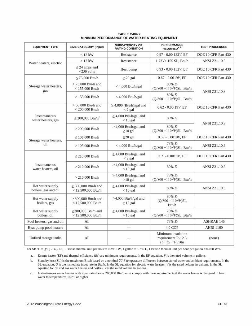
2012 Washington State Energy Code CE-73
TABLE C404.2 MINIMUM PERFORMANCE OF WATER-HEATING EQUIPMENT
EQUIPMENT TYPE SIZE CATEGORY (input) SUBCATEGORY OR RATING CONDITION
PERFORMANCE
REQUIREDa, b
TEST PROCEDURE
Water heaters, electric
≤12 kW Resistance 0.97 - 0.00 132V, EF DOE 10 CFR Part 430
> 12 kW Resistance 1.73V+ 155 SL, Btu/h ANSI Z21.10.3
≤24 amps and ≤250 volts
Heat pump 0.93 - 0.00 132V, EF DOE 10 CFR Part 430
Storage water heaters,
gas
≤75,000 Btu/h ≥20 gal 0.67 - 0.0019V, EF DOE 10 CFR Part 430
> 75,000 Btu/h and
≤155,000 Btu/h < 4,000 Btu/h/gal
80% Et
(Q/800 +110√V)SL, Btu/h
ANSI Z21.10.3
> 155,000 Btu/h < 4,000 Btu/h/gal 80% Et
(Q/800 +110√V)SL, Btu/h
Instantaneous
water heaters, gas
> 50,000 Btu/h and
< 200,000 Btu/h ≥4,000 (Btu/h)/gal and
< 2 gal 0.62 - 0.00 19V, EF DOE 10 CFR Part 430
≥200,000 Btu/hc ≥4,000 Btu/h/gal and
< 10 gal 80% Et
ANSI Z21.10.3
≥200,000 Btu/h ≥4,000 Btu/h/gal and
≥10 gal
80% Et
(Q/800 +110√V)SL, Btu/h
Storage water heaters,
oil
≤105,000 Btu/h ≥20 gal 0.59 - 0.0019V, EF DOE 10 CFR Part 430
>105,000 Btu/h < 4,000 Btu/h/gal 78% Et
(Q/800 +110√V)SL, Btu/h ANSI Z21.10.3
Instantaneous
water heaters, oil
≤210,000 Btu/h ≥4,000 Btu/h/gal and
< 2 gal 0.59 - 0.0019V, EF DOE 10 CFR Part 430
> 210,000 Btu/h ≥4,000 Btu/h/gal and
< 10 gal 80% Et ANSI Z21.10.3
> 210,000 Btu/h ≥4,000 Btu/h/gal and
≥10 gal
78% Et
(Q/800 +110√V)SL, Btu/h
Hot water supply
boilers, gas and oil ≥300,000 Btu/h and
< 12,500,000 Btu/h
≥4,000 Btu/h/gal and
< 10 gal 80% Et ANSI Z21.10.3
Hot water supply
boilers, gas ≥300,000 Btu/h and
< 12,500,000 Btu/h
≥4,000 Btu/h/gal and
≥10 gal
80% Et
(Q/800 +110√V)SL, Btu/h
Hot water supply
boilers, oil
≥300,000 Btu/h and
< 12,500,000 Btu/h
≥ 4,000 Btu/h/gal and
> 10 gal
78% Et
(Q/800 +110√V)SL, Btu/h
Pool heaters, gas and oil All — 78% Et ASHRAE 146
Heat pump pool heaters All — 4.0 COP AHRI 1160
Unfired storage tanks All —
Minimum insulation
requirement R-12.5
(h · ft2 · °F)/Btu
(none)
For SI: °C = [(°F) - 32]/1.8, 1 British thermal unit per hour = 0.2931 W, 1 gallon = 3.785 L, 1 British thermal unit per hour per gallon = 0.078 W/L.
a. Energy factor (EF) and thermal efficiency (Et ) are minimum requirements. In the EF equation, V is the rated volume in gallons.
b. Standby loss (SL) is the maximum Btu/h based on a nominal 70°F temperature difference between stored water and ambient requirements. In the
SL equation, Q is the nameplate input rate in Btu/h. In the SL equation for electric water heaters, V is the rated volume in gallons. In the SL equation for oil and gas water heaters and boilers, V is the rated volume in gallons.
c. Instantaneous water heaters with input rates below 200,000 Btu/h must comply with these requirements if the water heater is designed to heat
water to temperatures 180°F or higher.
CE-74 2012 Washington State Energy Code
C404.8 Shut-off controls. Systems designed to maintain
usage temperatures in hot water pipes, such as circulating
hot water systems or heat traced pipes, shall be equipped
with automatic time switches or other controls to turn off
the system during periods of nonuse.
C404.9 Domestic hot water meters. Each individual
dwelling unit in a Group R-2 multi-family residential
occupancy with central service shall be provided with a
domestic hot water meter to allow for domestic hot water
billing based on actual domestic hot water usage.
C404.10 Pools and in-ground permanently installed
spas (mandatory). Pools and in-ground permanently
installed spas shall comply with Sections C404.10.1
through C404.10.4.
C404.10.1 Heaters. Heat pump pool heaters shall have
a minimum COP of 4.0 determined in accordance with
ASHRAE Standard 146. Other pool heating equipment
shall comply with the applicable efficiencies in Section
C404.2.3.
All heaters shall be equipped with a readily
accessible on-off switch that is mounted outside of the
heater to allow shutting off the heater without
adjusting the thermostat setting. Gas-fired heaters shall
not be equipped with constant burning pilot lights.
C404.10.2 Time switches. Time switches or other
control method that can automatically turn off and on
heaters and pumps according to a preset schedule shall
be installed on all heaters and pumps. Heaters, pumps
and motors that have built in timers shall be deemed in
compliance with this requirement.
Exceptions:
1. Where public health standards require
24-hour pump operation.
2. Where pumps are required to operate solar-
and waste-heat-recovery pool heating
systems.
C404.10.3 Covers. Heated pools and in-ground
permanently installed spas shall be provided with a
vapor-retardant cover on or at the water surface. Pools
heated to more than 90°F shall have a pool cover with
a minimum insulation value of R-12, and the sides and
bottom of the pool shall also have a minimum
insulation value of R-12.
C404.10.4 Heat recovery. Heated indoor swimming
pools, spas or hot tubs with water surface area greater
than 200 square feet shall provide for energy
conservation by an exhaust air heat recovery system
that heats ventilation air, pool water or domestic hot
water. The heat recovery system shall be capable of
decreasing the exhaust air temperature at design
heating conditions (80°F indoor) by 36°F (10°C) in
Climate Zones 4C and 5B and 48°F (26.7°C) in
Climate Zone 6B.
Exception: Pools, spas or hot tubs that include
system(s) that provide equivalent recovered energy
on an annual basis through one of the following
methods:
1. Renewable energy;
2. Dehumidification heat recovery;
3. Waste heat recovery; or
4. A combination of these system sources
capable of providing at least 70 percent of the
heating energy required over an operating
season.
SECTION C405 ELECTRICAL POWER AND LIGHTING SYSTEMS
C405.1 General (mandatory). This section covers
lighting system controls, the connection of ballasts, the
maximum lighting power for interior applications,
electrical energy consumption, minimum acceptable
lighting equipment for exterior applications, and
minimum efficiencies for motors and transformers.
Exception: Dwelling units within commercial
buildings shall not be required to comply with Sections
C405.2 through C405.5 provided that a minimum of
75 percent of the lamps in permanently installed light
fixtures shall be high efficacy lamps.
Walk-in coolers and walk-in freezers shall comply
with C405.10. Refrigerated warehouse coolers and
refrigerated warehouse freezers shall comply with
C405.11.
C405.2 Lighting controls (mandatory). Lighting
systems shall be provided with controls as specified in
Sections C405.2.1, C405.2.2, C405.2.3, C405.2.4 and
C405.2.5.
Exception: Industrial or manufacturing process
areas, as may be required for production and safety.
C405.2.1 Manual lighting controls. All buildings
shall include manual lighting controls that meet the
requirements of Sections C405.2.1.1 and C405.2.1.2.
C405.2.1.1 Interior lighting controls. Each area
enclosed by walls or floor-to-ceiling partitions shall
have at least one manual control for the lighting
serving that area. The required controls shall be
located within the area served by the controls or be a
remote switch that identifies the lights served and
indicates their status.
2012 Washington State Energy Code CE-75
Exceptions:
1. Areas designated as security or emergency
areas that need to be continuously lighted.
2. Lighting in stairways or corridors that are
elements of the means of egress.
C405.2.1.2 Light reduction controls. Each area
that is required to have a manual control shall also
allow the occupant to reduce the connected lighting
load in a reasonably uniform illumination pattern by
at least 50 percent. Lighting reduction shall be
achieved by one of the following or other approved
method:
1. Controlling all lamps or luminaires;
2. Dual switching of alternate rows of
luminaires, alternate luminaires or alternate
lamps;
3. Switching the middle lamp luminaires
independently of the outer lamps; or
4. Switching each luminaire or each lamp.
Exception: Light reduction controls need not
be provided in the following areas and spaces:
1. Areas that have only one luminaire, with
rated power less than 100 watts.
2. Areas that are controlled by an
occupant-sensing device.
3. Corridors, equipment rooms, storerooms,
restrooms, public lobbies, electrical or
mechanical rooms.
4. Sleeping unit (see Section C405.2.3).
5. Spaces that use less than 0.6 watts per
square foot (6.5 W/m2).
6. Daylight spaces complying with Section
C405.2.2.3.2.
C405.2.2 Additional lighting controls. Each area that
is required to have a manual control shall also have
controls that meet the requirements of Sections
C405.2.2.1, C405.2.2.2 and C405.2.2.3.
Exception: Additional lighting controls need not
be provided in the following spaces:
1. Sleeping units.
2. Spaces where patient care is directly
provided.
3. Spaces where an automatic shutoff would
endanger occupant safety or security.
4. Lighting intended for continuous operation.
C405.2.2.1 Automatic time switch control devices.
Automatic time switch controls shall be installed to
control lighting in all areas of the building.
Automatic time switches shall have a minimum 7
day clock and be capable of being set for 7 different
day types per week and incorporate an automatic
holiday "shut-off" feature, which turns off all loads
for at least 24 hours and then resumes normally
scheduled operations. Automatic time switches shall
also have program back-up capabilities, which
prevent the loss of program and time settings for at
least 10 hours, if power is interrupted.
Exceptions:
1. Emergency egress lighting does not need to
be controlled by an automatic time switch.
2. Lighting in spaces controlled by occupancy
sensors does not need to be controlled by
automatic time switch controls.
The automatic time switch control device shall
include an override switching device that complies
with the following:
1. The override switch shall be in a readily
accessible location;
2. The override switch shall be located where
the lights controlled by the switch are visible;
or the switch shall provide a mechanism
which announces the area controlled by the
switch;
3. The override switch shall permit manual
operation;
4. The override switch, when initiated, shall
permit the controlled lighting to remain on for
a maximum of 2 hours; and
5. Any individual override switch shall control
the lighting for a maximum area of 5,000
square feet (465 m2).
Exception: Within malls, arcades, auditoriums,
single tenant retail spaces, industrial facilities and
arenas:
1. The time limit shall be permitted to exceed
2 hours provided the override switch is a
captive key device; and
2. The area controlled by the override switch
is permitted to exceed 5,000 square feet
(465 m2), but shall not exceed 20,000
square feet (1860 m2).
C405.2.2.2 Occupancy sensors. Occupancy sensors
shall be installed in all classrooms, conference/
meeting rooms, employee lunch and break rooms,
private offices, restrooms, warehouse spaces, storage
rooms and janitorial closets, and other spaces 300
square feet (28 m2) or less enclosed by floor-to-
ceiling height partitions. These automatic control
CE-76 2012 Washington State Energy Code
devices shall be installed to automatically turn off
lights within 30 minutes of all occupants leaving the
space, and shall either be manual on or shall be
controlled to automatically turn the lighting on to
not more than 50 percent power.
Exception: Full automatic-on controls shall be
permitted to control lighting in public corridors,
stairways, restrooms, primary building entrance
areas and lobbies, and areas where manual-on
operation would endanger the safety or security of
the room or building occupants.
C405.2.2.3 Daylight zone control. Daylight zones
shall be designed such that lights in the daylight
zone are controlled independently of general area
lighting and are controlled in accordance with
Section C405.2.2.3.2. Each daylight control zone
shall not exceed 2,500 square feet (232 m2).
Contiguous daylight zones adjacent to vertical
fenestration are allowed to be controlled by a single
controlling device provided that they do not include
zones facing more than two adjacent cardinal
orientations (i.e., north, east, south, west). The
primary daylight zone shall be controlled separately
from the secondary daylight zone. Daylight zones
under skylights more than 15 feet (4572 mm) from
the perimeter shall be controlled separately from
daylight zones adjacent to vertical fenestration.
Controls shall:
1. Control only luminaires within the daylit area.
2. Incorporate time-delay circuits to prevent
cycling of light level changes of less than
three minutes.
Exception: Daylight zones enclosed by walls or
ceiling height partitions and containing two or
fewer light fixtures are not required to have a
separate switch for general area lighting.
C405.2.2.3.1 Reserved.
C405.2.2.3.2 Automatic daylighting controls.
Setpoint and other controls for calibrating the
lighting control device shall be readily accessible.
Daylighting controls device shall be capable of
automatically reducing the lighting power in
response to available daylight by either one of the
following methods:
1. Continuous dimming using dimming
ballasts and daylight-sensing automatic
controls that are capable of reducing the
power of general lighting in the daylit zone
continuously to less than 20 percent of
rated power at maximum light output.
2.
Stepped dimming using multi-level
switching and daylight-sensing controls
that are capable of reducing lighting power
automatically. The system shall provide a
minimum of two control channels per zone
and be installed in a manner such that at
least one control step is between 50 percent
and 70 percent of design lighting power and
another control step is no greater than 35
percent of design power, and the system is
capable of automatically turning the system
off.
C405.2.2.3.3 Reserved.
C405.2.3 Specific application controls. Specific
application controls shall be provided for the
following:
1. Display and accent light shall be controlled by a
dedicated control which is independent of the
controls for other lighting within the room or
space.
2. Lighting in cases used for display case purposes
shall be controlled by a dedicated control which
is independent of the controls for other lighting
within the room or space.
3. Hotel and motel sleeping units and guest suites
shall have a master control device at the main
room entry that controls all permanently
installed luminaires and switched receptacles.
Where a hotel/motel includes more than 50
rooms, controls shall be automatic to ensure all
power to the lights and switched outlets are
turned off when the occupant is not in the room.
4. Supplemental task lighting, including
permanently installed under-shelf or
under-cabinet lighting, shall be automatically
shut off whenever that space is unoccupied and
shall have a control device integral to the
luminaires or be controlled by a wall-mounted
control device provided the control device is
readily accessible.
5. Lighting for nonvisual applications, such as
plant growth and food warming, shall be
controlled by a dedicated control which is
independent of the controls for other lighting
within the room or space.
6. Lighting equipment that is for sale or for
demonstrations in lighting education shall be
controlled by a dedicated control which is
independent of the controls for other lighting
within the room or space.
2012 Washington State Energy Code CE-77
7. Luminaires serving the exit access and
providing means of egress illumination required
by Section 1006.1 of the International Building
Code, including luminaires that function as both
normal and emergency means of egress
illumination shall be controlled by a
combination of listed emergency relay and
occupancy sensors, or signal from another
building control system, that automatically
shuts off the lighting when the areas served by
that illumination are unoccupied.
Exception: Means of egress illumination
serving the exit access that does not exceed
0.05 watts per square foot of building area is
exempt from this requirement.
C405.2.4 Exterior lighting controls. Lighting not
designated for dusk-to-dawn operation shall be
controlled by either a combination of a photosensor
and a time switch, or an astronomical time switch.
Lighting designated for dusk-to-dawn operation shall
be controlled by an astronomical time switch or
photosensor. All time switches shall be capable of
retaining programming and the time setting during loss
of power for a period of at least 10 hours.
C405.2.5 Area controls. The maximum lighting
power that may be controlled from a single switch or
automatic control shall not exceed that which is
provided by a 20 ampere circuit loaded to not more
than 80 percent. A master control may be installed
provided the individual switches retain their capability
to function independently. Circuit breakers may not be
used as the sole means of switching.
Exception: Areas less than 5 percent of the
building footprint for footprints over 100,000 ft2.
C405.3 Reserved.
C405.4 Exit signs (mandatory). Internally illuminated
exit signs shall not exceed 5 watts per side.
C405.5 Interior lighting power requirements
(prescriptive). A building complies with this section if
its total connected lighting power calculated under
Section C405.5.1 is no greater than the interior lighting
power calculated under Section C405.5.2.
C405.5.1 Total connected interior lighting power.
The total connected interior lighting power (watts)
shall be the sum of the watts of all interior lighting
equipment as determined in accordance with Sections
C405.5.1.1 through C405.5.1.4.
Exceptions:
1. The connected power associated with the
following lighting equipment is not included
in calculating total connected lighting power.
1.1.
Professional sports arena playing field
lighting.
1.2. Emergency lighting automatically off
during normal building operation.
1.3. Lighting in spaces specifically designed
for use by occupants with special
lighting needs including the visually
impaired and other medical and
age-related issues.
1.4. Casino gaming areas.
1.5. General area lighting power in industrial
and manufacturing occupancies
dedicated to the inspection or quality
control of goods and products.
2. Lighting equipment used for the following
shall be exempt provided that it is in addition
to general lighting and is controlled by an
independent control device:
2.1. Task lighting for medical and dental
purposes.
2.2. Display lighting for exhibits in galleries,
museums and monuments.
3. Lighting for theatrical purposes, including
performance, stage, film production and video
production.
4. Lighting for photographic processes.
5. Lighting integral to equipment or
instrumentation and is installed by the
manufacturer.
6. Task lighting for plant growth or
maintenance.
7. Advertising signage or directional signage.
8. In restaurant buildings and areas, lighting for
food warming or integral to food preparation
equipment.
9. Lighting equipment that is for sale.
10. Lighting demonstration equipment in lighting
education facilities.
11. Lighting approved because of safety or
emergency considerations, inclusive of exit
lights.
12. Lighting integral to both open and glass
enclosed refrigerator and freezer cases.
13. Lighting in retail display windows, provided
the display area is enclosed by ceiling-height
partitions.
14. Furniture mounted supplemental task lighting
that is controlled by automatic shutoff.
15. Lighting used for aircraft painting.
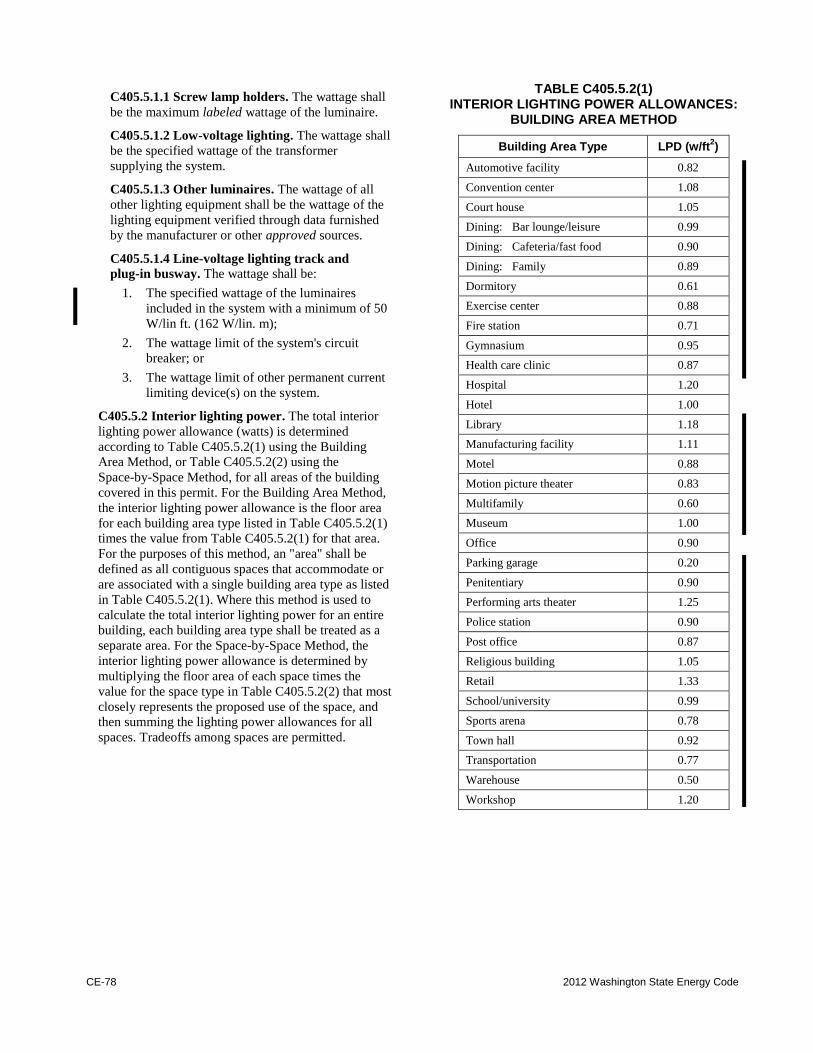
CE-78 2012 Washington State Energy Code
C405.5.1.1 Screw lamp holders. The wattage shall
be the maximum labeled wattage of the luminaire.
C405.5.1.2 Low-voltage lighting. The wattage shall
be the specified wattage of the transformer
supplying the system.
C405.5.1.3 Other luminaires. The wattage of all
other lighting equipment shall be the wattage of the
lighting equipment verified through data furnished
by the manufacturer or other approved sources.
C405.5.1.4 Line-voltage lighting track and
plug-in busway. The wattage shall be:
1. The specified wattage of the luminaires
included in the system with a minimum of 50
W/lin ft. (162 W/lin. m);
2. The wattage limit of the system's circuit
breaker; or
3. The wattage limit of other permanent current
limiting device(s) on the system.
C405.5.2 Interior lighting power. The total interior
lighting power allowance (watts) is determined
according to Table C405.5.2(1) using the Building
Area Method, or Table C405.5.2(2) using the
Space-by-Space Method, for all areas of the building
covered in this permit. For the Building Area Method,
the interior lighting power allowance is the floor area
for each building area type listed in Table C405.5.2(1)
times the value from Table C405.5.2(1) for that area.
For the purposes of this method, an "area" shall be
defined as all contiguous spaces that accommodate or
are associated with a single building area type as listed
in Table C405.5.2(1). Where this method is used to
calculate the total interior lighting power for an entire
building, each building area type shall be treated as a
separate area. For the Space-by-Space Method, the
interior lighting power allowance is determined by
multiplying the floor area of each space times the
value for the space type in Table C405.5.2(2) that most
closely represents the proposed use of the space, and
then summing the lighting power allowances for all
spaces. Tradeoffs among spaces are permitted.
TABLE C405.5.2(1) INTERIOR LIGHTING POWER ALLOWANCES:
BUILDING AREA METHOD
Building Area Type LPD (w/ft2)
Automotive facility 0.82
Convention center 1.08
Court house 1.05
Dining: Bar lounge/leisure 0.99
Dining: Cafeteria/fast food 0.90
Dining: Family 0.89
Dormitory 0.61
Exercise center 0.88
Fire station 0.71
Gymnasium 0.95
Health care clinic 0.87
Hospital 1.20
Hotel 1.00
Library 1.18
Manufacturing facility 1.11
Motel 0.88
Motion picture theater 0.83
Multifamily 0.60
Museum 1.00
Office 0.90
Parking garage 0.20
Penitentiary 0.90
Performing arts theater 1.25
Police station 0.90
Post office 0.87
Religious building 1.05
Retail 1.33
School/university 0.99
Sports arena 0.78
Town hall 0.92
Transportation 0.77
Warehouse 0.50
Workshop 1.20
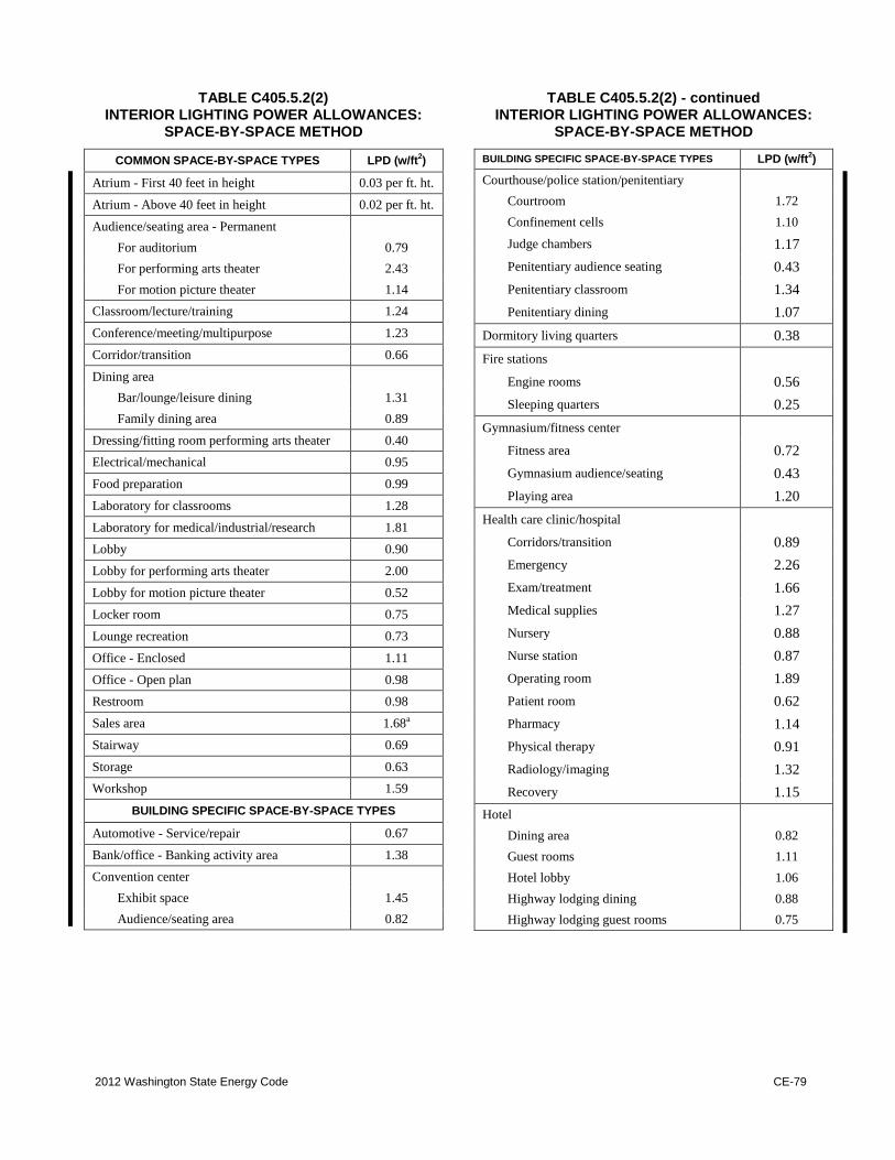
2012 Washington State Energy Code CE-79
TABLE C405.5.2(2) INTERIOR LIGHTING POWER ALLOWANCES:
SPACE-BY-SPACE METHOD
COMMON SPACE-BY-SPACE TYPES LPD (w/ft2)
Atrium - First 40 feet in height 0.03 per ft. ht.
Atrium - Above 40 feet in height 0.02 per ft. ht.
Audience/seating area - Permanent
For auditorium 0.79
For performing arts theater 2.43
For motion picture theater 1.14
Classroom/lecture/training 1.24
Conference/meeting/multipurpose 1.23
Corridor/transition 0.66
Dining area
Bar/lounge/leisure dining 1.31
Family dining area 0.89
Dressing/fitting room performing arts theater 0.40
Electrical/mechanical 0.95
Food preparation 0.99
Laboratory for classrooms 1.28
Laboratory for medical/industrial/research 1.81
Lobby 0.90
Lobby for performing arts theater 2.00
Lobby for motion picture theater 0.52
Locker room 0.75
Lounge recreation 0.73
Office - Enclosed 1.11
Office - Open plan 0.98
Restroom 0.98
Sales area 1.68a
Stairway 0.69
Storage 0.63
Workshop 1.59
BUILDING SPECIFIC SPACE-BY-SPACE TYPES
Automotive - Service/repair 0.67
Bank/office - Banking activity area 1.38
Convention center
Exhibit space 1.45
Audience/seating area 0.82
TABLE C405.5.2(2) - continued INTERIOR LIGHTING POWER ALLOWANCES:
SPACE-BY-SPACE METHOD
BUILDING SPECIFIC SPACE-BY-SPACE TYPES LPD (w/ft2)
Courthouse/police station/penitentiary
Courtroom 1.72
Confinement cells 1.10
Judge chambers 1.17
Penitentiary audience seating 0.43
Penitentiary classroom 1.34
Penitentiary dining 1.07
Dormitory living quarters 0.38
Fire stations
Engine rooms 0.56
Sleeping quarters 0.25
Gymnasium/fitness center
Fitness area 0.72
Gymnasium audience/seating 0.43
Playing area 1.20
Health care clinic/hospital
Corridors/transition 0.89
Emergency 2.26
Exam/treatment 1.66
Medical supplies 1.27
Nursery 0.88
Nurse station 0.87
Operating room 1.89
Patient room 0.62
Pharmacy 1.14
Physical therapy 0.91
Radiology/imaging 1.32
Recovery 1.15
Hotel
Dining area 0.82
Guest rooms 1.11
Hotel lobby 1.06
Highway lodging dining 0.88
Highway lodging guest rooms 0.75
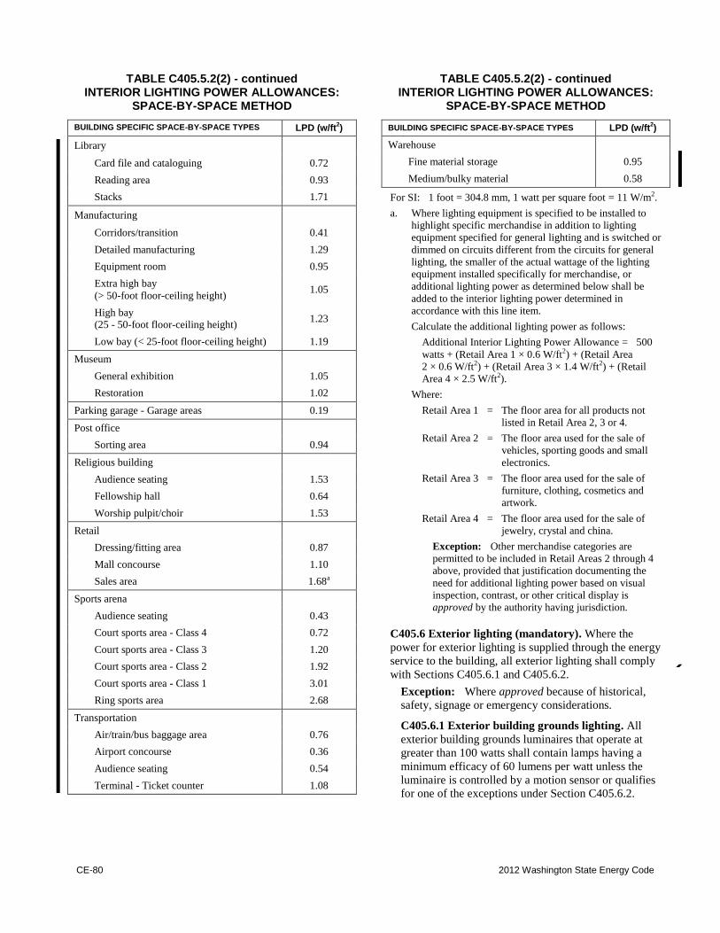
CE-80 2012 Washington State Energy Code
TABLE C405.5.2(2) - continued INTERIOR LIGHTING POWER ALLOWANCES:
SPACE-BY-SPACE METHOD
BUILDING SPECIFIC SPACE-BY-SPACE TYPES LPD (w/ft2)
Library
Card file and cataloguing 0.72
Reading area 0.93
Stacks 1.71
Manufacturing
Corridors/transition 0.41
Detailed manufacturing 1.29
Equipment room 0.95
Extra high bay
(> 50-foot floor-ceiling height) 1.05
High bay (25 - 50-foot floor-ceiling height)
1.23
Low bay (< 25-foot floor-ceiling height) 1.19
Museum
General exhibition 1.05
Restoration 1.02
Parking garage - Garage areas 0.19
Post office
Sorting area 0.94
Religious building
Audience seating 1.53
Fellowship hall 0.64
Worship pulpit/choir 1.53
Retail
Dressing/fitting area 0.87
Mall concourse 1.10
Sales area 1.68a
Sports arena
Audience seating 0.43
Court sports area - Class 4 0.72
Court sports area - Class 3 1.20
Court sports area - Class 2 1.92
Court sports area - Class 1 3.01
Ring sports area 2.68
Transportation
Air/train/bus baggage area 0.76
Airport concourse 0.36
Audience seating 0.54
Terminal - Ticket counter 1.08
TABLE C405.5.2(2) - continued INTERIOR LIGHTING POWER ALLOWANCES:
SPACE-BY-SPACE METHOD
BUILDING SPECIFIC SPACE-BY-SPACE TYPES LPD (w/ft2)
Warehouse
Fine material storage 0.95
Medium/bulky material 0.58
For SI: 1 foot = 304.8 mm, 1 watt per square foot = 11 W/m2.
a. Where lighting equipment is specified to be installed to
highlight specific merchandise in addition to lighting
equipment specified for general lighting and is switched or
dimmed on circuits different from the circuits for general
lighting, the smaller of the actual wattage of the lighting
equipment installed specifically for merchandise, or
additional lighting power as determined below shall be
added to the interior lighting power determined in
accordance with this line item.
Calculate the additional lighting power as follows:
Additional Interior Lighting Power Allowance = 500
watts + (Retail Area 1 × 0.6 W/ft2) + (Retail Area
2 × 0.6 W/ft2) + (Retail Area 3 × 1.4 W/ft2) + (Retail
Area 4 × 2.5 W/ft2).
Where:
Retail Area 1 = The floor area for all products not
listed in Retail Area 2, 3 or 4.
Retail Area 2 = The floor area used for the sale of
vehicles, sporting goods and small
electronics.
Retail Area 3 = The floor area used for the sale of
furniture, clothing, cosmetics and
artwork.
Retail Area 4 = The floor area used for the sale of
jewelry, crystal and china.
Exception: Other merchandise categories are
permitted to be included in Retail Areas 2 through 4
above, provided that justification documenting the
need for additional lighting power based on visual
inspection, contrast, or other critical display is
approved by the authority having jurisdiction.
C405.6 Exterior lighting (mandatory). Where the
power for exterior lighting is supplied through the energy
service to the building, all exterior lighting shall comply
with Sections C405.6.1 and C405.6.2.
Exception: Where approved because of historical,
safety, signage or emergency considerations.
C405.6.1 Exterior building grounds lighting. All
exterior building grounds luminaires that operate at
greater than 100 watts shall contain lamps having a
minimum efficacy of 60 lumens per watt unless the
luminaire is controlled by a motion sensor or qualifies
for one of the exceptions under Section C405.6.2.
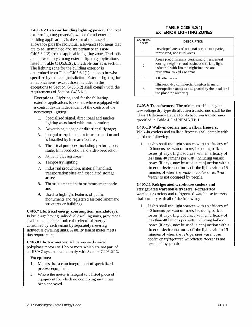
2012 Washington State Energy Code CE-81
C405.6.2 Exterior building lighting power. The total
exterior lighting power allowance for all exterior
building applications is the sum of the base site
allowance plus the individual allowances for areas that
are to be illuminated and are permitted in Table
C405.6.2(2) for the applicable lighting zone. Tradeoffs
are allowed only among exterior lighting applications
listed in Table C405.6.2(2), Tradable Surfaces section.
The lighting zone for the building exterior is
determined from Table C405.6.2(1) unless otherwise
specified by the local jurisdiction. Exterior lighting for
all applications (except those included in the
exceptions to Section C405.6.2) shall comply with the
requirements of Section C405.6.1.
Exception: Lighting used for the following
exterior applications is exempt where equipped with
a control device independent of the control of the
nonexempt lighting:
1. Specialized signal, directional and marker
lighting associated with transportation;
2. Advertising signage or directional signage;
3. Integral to equipment or instrumentation and
is installed by its manufacturer;
4. Theatrical purposes, including performance,
stage, film production and video production;
5. Athletic playing areas;
6. Temporary lighting;
7. Industrial production, material handling,
transportation sites and associated storage
areas;
8. Theme elements in theme/amusement parks;
and
9. Used to highlight features of public
monuments and registered historic landmark
structures or buildings.
C405.7 Electrical energy consumption (mandatory).
In buildings having individual dwelling units, provisions
shall be made to determine the electrical energy
consumed by each tenant by separately metering
individual dwelling units. A utility tenant meter meets
this requirement.
C405.8 Electric motors. All permanently wired
polyphase motors of 1 hp or more which are not part of
an HVAC system shall comply with Section C403.2.13.
Exceptions:
1. Motors that are an integral part of specialized
process equipment.
2. Where the motor is integral to a listed piece of
equipment for which no complying motor has
been approved.
TABLE C405.6.2(1) EXTERIOR LIGHTING ZONES
LIGHTING ZONE
DESCRIPTION
1 Developed areas of national parks, state parks,
forest land, and rural areas
2
Areas predominantly consisting of residential
zoning, neighborhood business districts, light
industrial with limited nighttime use and residential mixed use areas
3 All other areas
4
High-activity commercial districts in major
metropolitan areas as designated by the local land use planning authority
C405.9 Transformers. The minimum efficiency of a
low voltage dry-type distribution transformer shall be the
Class I Efficiency Levels for distribution transformers
specified in Table 4-2 of NEMA TP-1.
C405.10 Walk-in coolers and walk-in freezers.
Walk-in coolers and walk-in freezers shall comply with
all of the following:
1. Lights shall use light sources with an efficacy of
40 lumens per watt or more, including ballast
losses (if any). Light sources with an efficacy of
less than 40 lumens per watt, including ballast
losses (if any), may be used in conjunction with a
timer or device that turns off the lights within 15
minutes of when the walk-in cooler or walk-in
freezer is not occupied by people.
C405.11 Refrigerated warehouse coolers and
refrigerated warehouse freezers. Refrigerated
warehouse coolers and refrigerated warehouse freezers
shall comply with all of the following:
1. Lights shall use light sources with an efficacy of
40 lumens per watt or more, including ballast
losses (if any). Light sources with an efficacy of
less than 40 lumens per watt, including ballast
losses (if any), may be used in conjunction with a
timer or device that turns off the lights within 15
minutes of when the refrigerated warehouse
cooler or refrigerated warehouse freezer is not
occupied by people.
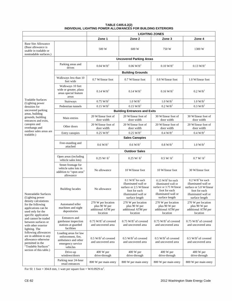
CE-82 2012 Washington State Energy Code
TABLE C405.6.2(2) INDIVIDUAL LIGHTING POWER ALLOWANCES FOR BUILDING EXTERIORS
LIGHTING ZONES
Zone 1 Zone 2 Zone 3 Zone 4
Base Site Allowance (Base allowance is
usable in tradable or
nontradable surfaces.)
500 W 600 W 750 W 1300 W
Tradable Surfaces (Lighting power
densities for
uncovered parking areas, building
grounds, building
entrances and exits, canopies and
overhangs and
outdoor sales areas are tradable.)
Uncovered Parking Areas
Parking areas and drives
0.04 W/ft2 0.06 W/ft2
0.10 W/ft2 0.13 W/ft2
Building Grounds
Walkways less than 10 feet wide
0.7 W/linear foot 0.7 W/linear foot 0.8 W/linear foot 1.0 W/linear foot
Walkways 10 feet
wide or greater, plaza areas special feature
areas
0.14 W/ft2 0.14 W/ft2
0.16 W/ft2 0.2 W/ft2
Stairways 0.75 W/ft2 1.0 W/ft2
1.0 W/ft2 1.0 W/ft2
Pedestrian tunnels 0.15 W/ft2 0.15 W/ft2
0.2 W/ft2 0.3 W/ft2
Building Entrances and Exits
Main entries 20 W/linear foot of
door width 20 W/linear foot of
door width 30 W/linear foot of
door width 30 W/linear foot of
door width
Other doors 20 W/linear foot of
door width
20 W/linear foot of
door width
20 W/linear foot of
door width
20 W/linear foot of
door width
Entry canopies 0.25 W/ft2 0.25 W/ft2
0.4 W/ft2 0.4 W/ft2
Sales Canopies
Free-standing and attached
0.6 W/ft2 0.6 W/ft2
0.8 W/ft2 1.0 W/ft2
Outdoor Sales
Open areas (including
vehicle sales lots) 0.25 W/ ft2
0.25 W/ ft2 0.5 W/ ft2
0.7 W/ ft2
Street frontage for vehicle sales lots in
addition to “open area”
allowance
No allowance 10 W/linear foot 10 W/linear foot 30 W/linear foot
Nontradable Surfaces (Lighting power
density calculations for the following
applications can be
used only for the specific application
and cannot be traded
between surfaces or
with other exterior
lighting. The
following allowances are in addition to any
allowance otherwise
permitted in the “Tradable Surfaces”
section of this table.)
Building facades No allowance
0.1 W/ft2
for each
illuminated wall or
surface or 2.5 W/linear foot for each
illuminated wall or
surface length
0.15 W/ft2
for each
illuminated wall or
surface or 3.75 W/linear
foot for each illuminated wall or
surface length
0.2 W/ft2
for each
illuminated wall or
surface or 5.0 W/linear foot for each
illuminated wall or
surface length
Automated teller
machines and night depositories
270 W per location plus 90 W per
additional ATM per
location
270 W per location plus 90 W per
additional ATM per
location
270 W per location plus 90 W per
additional ATM per
location
270 W per location plus 90 W per
additional ATM per
location
Entrances and gatehouse inspection
stations at guarded facilities
0.75 W/ft2 of covered
and uncovered area
0.75 W/ft2 of covered
and uncovered area
0.75 W/ft2 of covered
and uncovered area
0.75 W/ft2 of covered
and uncovered area
Loading areas for law enforcement, fire,
ambulance and other
emergency service
vehicles
0.5 W/ft2 of covered
and uncovered area
0.5 W/ft2 of covered
and uncovered area
0.5 W/ft2 of covered
and uncovered area
0.5 W/ft2 of covered
and uncovered area
Drive-up windows/doors
400 W per drive-through
400 W per drive-through
400 W per drive-through
400 W per drive-through
Parking near 24-hour
retail entrances 800 W per main entry 800 W per main entry 800 W per main entry 800 W per main entry
For SI: 1 foot = 304.8 mm, 1 watt per square foot = W/0.0929 m2.
2012 Washington State Energy Code CE-83
C405.12 Escalators and moving walks.
C405.12.1 Variable speed escalators. Where variable
speed escalators and moving walks are permitted by
the administrative authority, all escalators and moving
walks shall reduce their operating speed to no more
than 15 feet per minute when no passengers have been
detected for a period of time not exceeding three times
the amount of time required to transfer a passenger
between landings. Such escalators and moving walks
shall comply with the requirements of ANSI/ASME
A17.1 for variable speed escalators and moving walks.
Exception: A power factor controller that reduces
operating voltage in response to light loading
conditions may be provided in place of the variable
speed function.
C405.12.2 Regenerative drive. Escalators designed
either for one-way down operation only or for
reversible operation shall have variable frequency
regenerative drives that supply electrical energy to the
building electrical system when loaded with more than
5 passengers.
C405.13 Electrical power and lighting systems
commissioning and completion requirements.
Electrical power and lighting systems shall be
commissioned and completed in accordance with Section
C408.
SECTION C406 ADDITIONAL EFFICIENCY PACKAGE OPTIONS
Sections C406.1 through C406.4 are not adopted.
SECTION C407 TOTAL BUILDING PERFORMANCE
C407.1 Scope. This section establishes criteria for
compliance using total building performance. All
systems and loads shall be included in determining the
total building performance including, but not limited to:
Heating systems, cooling systems, service water heating,
fan systems, lighting power, receptacle loads and process
loads.
C407.2 Mandatory requirements. Compliance with
this section requires that the criteria of Sections C402.4,
C403.2, C404 and C405 be met.
The building permit application for projects utilizing
this method shall include in one submittal all building
and mechanical drawings and all information necessary
to verify that the building envelope and mechanical
design for the project corresponds with the annual energy
analysis. If credit is proposed to be taken for lighting
energy savings, then an electrical permit application shall
also be submitted and approved prior to the issuance of
the building permit. If credit is proposed to be taken for
energy savings from other components, then the
corresponding permit application (e.g., plumbing, boiler,
etc.) shall also be submitted and approved prior to the
building permit application. Otherwise, components of
the project that would not be approved as part of a
building permit application shall be modeled the same in
both the proposed building and the standard reference
design and shall comply with the requirements of this
code.
C407.3 Performance-based compliance. Compliance
based on total building performance requires that a
proposed building (proposed design) be shown to have
an annual energy consumption based on site energy
expressed in Btu and Btu per square foot of conditioned
floor area that is less than or equal to the annual energy
consumption of the standard reference design.
C407.4 Documentation. Documentation verifying that
the methods and accuracy of compliance software tools
conform to the provisions of this section shall be
provided to the code official.
C407.4.1 Compliance report. Building permit
submittals shall include a report that documents that
the proposed design has annual energy consumption
less than or equal to the annual energy consumption of
the standard reference design. The compliance
documentation shall include the following information:
1. Address of the building;
2. An inspection checklist documenting the
building component characteristics of the
proposed design as listed in Table C407.5.1(1).
The inspection checklist shall show the
estimated annual energy consumption for both
the standard reference design and the proposed
design;
3. Name of individual completing the compliance
report; and
4. Name and version of the compliance software
tool.
C407.4.2 Additional documentation. The code
official shall be permitted to require the following
documents:
1. Documentation of the building component
characteristics of the standard reference design;
CE-84 2012 Washington State Energy Code
2. Thermal zoning diagrams consisting of floor
plans showing the thermal zoning scheme for
standard reference design and proposed design;
3. Input and output report(s) from the energy
analysis simulation program containing the
complete input and output files, as applicable.
The output file shall include energy use totals
and energy use by energy source and end-use
served, total hours that space conditioning loads
are not met and any errors or warning messages
generated by the simulation tool as applicable;
4. An explanation of any error or warning
messages appearing in the simulation tool
output; and
5. A certification signed by the builder providing
the building component characteristics of the
proposed design as given in Table C407.5.1(1).
C407.5 Calculation procedure. Except as specified by
this section, the standard reference design and proposed
design shall be configured and analyzed using identical
methods and techniques.
C407.5.1 Building specifications. The standard
reference design and proposed design shall be
configured and analyzed as specified by Table
C407.5.1(1). Table C407.5.1(1) shall include by
reference all notes contained in Table C402.2.
C407.5.2 Thermal blocks. The standard reference
design and proposed design shall be analyzed using
identical thermal blocks as specified in Section
C407.5.2.1, C407.5.2.2 or C407.5.2.3.
C407.5.2.1 HVAC zones designed. Where HVAC
zones are defined on HVAC design drawings, each
HVAC zone shall be modeled as a separate thermal
block.
Exception: Different HVAC zones shall be
allowed to be combined to create a single thermal
block or identical thermal blocks to which
multipliers are applied provided:
1. The space use classification is the same
throughout the thermal block.
2. All HVAC zones in the thermal block that
are adjacent to glazed exterior walls face
the same orientation or their orientations
are within 45 degrees (0.79 rad) of each
other.
3. All of the zones are served by the same
HVAC system or by the same kind of
HVAC system.
C407.5.2.2 HVAC zones not designed. Where
HVAC zones have not yet been designed, thermal
blocks shall be defined based on similar internal
load densities, occupancy, lighting, thermal and
temperature schedules, and in combination with the
following guidelines:
1. Separate thermal blocks shall be assumed for
interior and perimeter spaces. Interior spaces
shall be those located more than 15 feet (4572
mm) from an exterior wall. Perimeter spaces
shall be those located closer than 15 feet
(4572 mm) from an exterior wall.
2. Separate thermal blocks shall be assumed for
spaces adjacent to glazed exterior walls: A
separate zone shall be provided for each
orientation, except orientations that differ by
no more than 45 degrees (0.79 rad) shall be
permitted to be considered to be the same
orientation. Each zone shall include floor area
that is 15 feet (4572 mm) or less from a
glazed perimeter wall, except that floor area
within 15 feet (4572 mm) of glazed perimeter
walls having more than one orientation shall
be divided proportionately between zones.
3. Separate thermal blocks shall be assumed for
spaces having floors that are in contact with
the ground or exposed to ambient conditions
from zones that do not share these features.
4. Separate thermal blocks shall be assumed for
spaces having exterior ceiling or roof
assemblies from zones that do not share these
features.
C407.5.2.3 Multifamily residential buildings.
Residential spaces shall be modeled using one
thermal block per space except that those facing the
same orientations are permitted to be combined into
one thermal block. Corner units and units with roof
or floor loads shall only be combined with units
sharing these features.
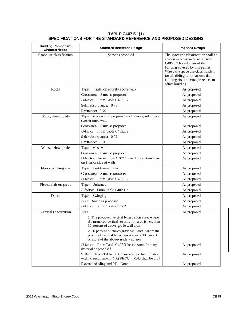
2012 Washington State Energy Code CE-85
TABLE C407.5.1(1) SPECIFICATIONS FOR THE STANDARD REFERENCE AND PROPOSED DESIGNS
Building Component Characteristics
Standard Reference Design Proposed Design
Space use classification Same as proposed The space use classification shall be
chosen in accordance with Table
C405.5.2 for all areas of the
building covered by this permit.
Where the space use classification
for a building is not known, the
building shall be categorized as an
office building.
Roofs Type: Insulation entirely above deck As proposed
Gross area: Same as proposed As proposed
U-factor: From Table C402.1.2 As proposed
Solar absorptance: 0.75 As proposed
Emittance: 0.90 As proposed
Walls, above-grade Type: Mass wall if proposed wall is mass; otherwise
steel-framed wall
As proposed
Gross area: Same as proposed As proposed
U-factor: From Table C402.1.2 As proposed
Solar absorptance: 0.75 As proposed
Emittance: 0.90 As proposed
Walls, below-grade Type: Mass wall As proposed
Gross area: Same as proposed As proposed
U-Factor: From Table C402.1.2 with insulation layer
on interior side of walls
As proposed
Floors, above-grade Type: Joist/framed floor As proposed
Gross area: Same as proposed As proposed
U-factor: From Table C402.1.2 As proposed
Floors, slab-on-grade Type: Unheated As proposed
F-factor: From Table C402.1.2 As proposed
Doors Type: Swinging As proposed
Area: Same as proposed As proposed
U-factor: From Table C402.2 As proposed
Vertical Fenestration Area As proposed
1. The proposed vertical fenestration area; where
the proposed vertical fenestration area is less than
30 percent of above-grade wall area.
2. 30 percent of above-grade wall area; where the
proposed vertical fenestration area is 30 percent
or more of the above-grade wall area.
U-factor: From Table C402.3 for the same framing
material as proposed
As proposed
SHGC: From Table C402.3 except that for climates
with no requirement (NR) SHGC .= 0.40 shall be used
As proposed
External shading and PF: None As proposed
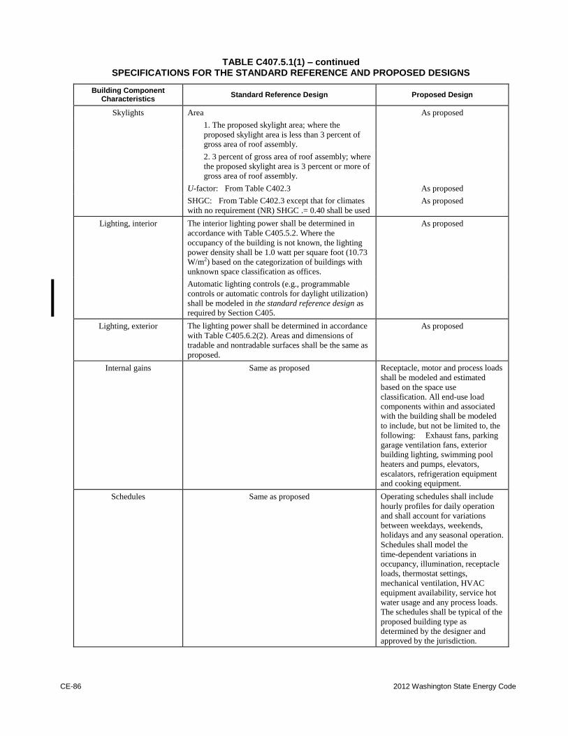
CE-86 2012 Washington State Energy Code
TABLE C407.5.1(1) – continued SPECIFICATIONS FOR THE STANDARD REFERENCE AND PROPOSED DESIGNS
Building Component Characteristics
Standard Reference Design Proposed Design
Skylights Area As proposed
1. The proposed skylight area; where the
proposed skylight area is less than 3 percent of
gross area of roof assembly.
2. 3 percent of gross area of roof assembly; where
the proposed skylight area is 3 percent or more of
gross area of roof assembly.
U-factor: From Table C402.3 As proposed
SHGC: From Table C402.3 except that for climates
with no requirement (NR) SHGC .= 0.40 shall be used
As proposed
Lighting, interior The interior lighting power shall be determined in
accordance with Table C405.5.2. Where the
occupancy of the building is not known, the lighting
power density shall be 1.0 watt per square foot (10.73
W/m2) based on the categorization of buildings with
unknown space classification as offices.
As proposed
Automatic lighting controls (e.g., programmable
controls or automatic controls for daylight utilization)
shall be modeled in the standard reference design as
required by Section C405.
Lighting, exterior The lighting power shall be determined in accordance
with Table C405.6.2(2). Areas and dimensions of
tradable and nontradable surfaces shall be the same as
proposed.
As proposed
Internal gains Same as proposed Receptacle, motor and process loads
shall be modeled and estimated
based on the space use
classification. All end-use load
components within and associated
with the building shall be modeled
to include, but not be limited to, the
following: Exhaust fans, parking
garage ventilation fans, exterior
building lighting, swimming pool
heaters and pumps, elevators,
escalators, refrigeration equipment
and cooking equipment.
Schedules Same as proposed Operating schedules shall include
hourly profiles for daily operation
and shall account for variations
between weekdays, weekends,
holidays and any seasonal operation.
Schedules shall model the
time-dependent variations in
occupancy, illumination, receptacle
loads, thermostat settings,
mechanical ventilation, HVAC
equipment availability, service hot
water usage and any process loads.
The schedules shall be typical of the
proposed building type as
determined by the designer and
approved by the jurisdiction.
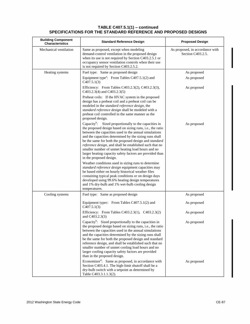
2012 Washington State Energy Code CE-87
TABLE C407.5.1(1) – continued SPECIFICATIONS FOR THE STANDARD REFERENCE AND PROPOSED DESIGNS
Building Component Characteristics
Standard Reference Design Proposed Design
Mechanical ventilation Same as proposed, except when modeling
demand-control ventilation in the proposed design
when its use is not required by Section C403.2.5.1 or
occupancy sensor ventilation controls when their use
is not required by Section C403.2.5.2.
As proposed, in accordance with
Section C403.2.5.
Heating systems Fuel type: Same as proposed design As proposed
Equipment typea: From Tables C407.5.1(2) and
C407.5.1(3) As proposed
Efficiency: From Tables C403.2.3(2), C403.2.3(3),
C403.2.3(4) and C403.2.3(5)
As proposed
Preheat coils: If the HVAC system in the proposed
design has a preheat coil and a preheat coil can be
modeled in the standard reference design, the
standard reference design shall be modeled with a
preheat coil controlled in the same manner as the
proposed design.
Capacityb: Sized proportionally to the capacities in
the proposed design based on sizing runs, i.e., the ratio
between the capacities used in the annual simulations
and the capacities determined by the sizing runs shall
be the same for both the proposed design and standard
reference design, and shall be established such that no
smaller number of unmet heating load hours and no
larger heating capacity safety factors are provided than
in the proposed design.
As proposed
Weather conditions used in sizing runs to determine
standard reference design equipment capacities may
be based either on hourly historical weather files
containing typical peak conditions or on design days
developed using 99.6% heating design temperatures
and 1% dry-bulb and 1% wet-bulb cooling design
temperatures.
Cooling systems Fuel type: Same as proposed design As proposed
Equipment typec: From Tables C407.5.1(2) and
C407.5.1(3)
As proposed
Efficiency: From Tables C403.2.3(1), C403.2.3(2)
and C403.2.3(3)
As proposed
Capacityb: Sized proportionally to the capacities in
the proposed design based on sizing runs, i.e., the ratio
between the capacities used in the annual simulations
and the capacities determined by the sizing runs shall
be the same for both the proposed design and standard
reference design, and shall be established such that no
smaller number of unmet cooling load hours and no
larger cooling capacity safety factors are provided
than in the proposed design.
As proposed
Economizerd: Same as proposed, in accordance with
Section C403.4.1. The high-limit shutoff shall be a
dry-bulb switch with a setpoint as determined by
Table C403.3.1.1.3(2).
As proposed
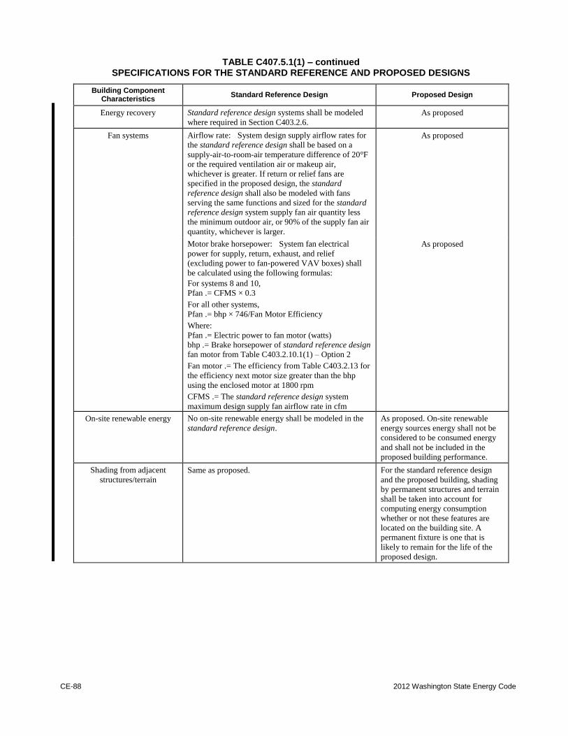
CE-88 2012 Washington State Energy Code
TABLE C407.5.1(1) – continued SPECIFICATIONS FOR THE STANDARD REFERENCE AND PROPOSED DESIGNS
Building Component Characteristics
Standard Reference Design Proposed Design
Energy recovery Standard reference design systems shall be modeled
where required in Section C403.2.6.
As proposed
Fan systems Airflow rate: System design supply airflow rates for
the standard reference design shall be based on a
supply-air-to-room-air temperature difference of 20°F
or the required ventilation air or makeup air,
whichever is greater. If return or relief fans are
specified in the proposed design, the standard
reference design shall also be modeled with fans
serving the same functions and sized for the standard
reference design system supply fan air quantity less
the minimum outdoor air, or 90% of the supply fan air
quantity, whichever is larger.
As proposed
Motor brake horsepower: System fan electrical
power for supply, return, exhaust, and relief
(excluding power to fan-powered VAV boxes) shall
be calculated using the following formulas:
For systems 8 and 10,
Pfan .= CFMS × 0.3
For all other systems,
Pfan .= bhp × 746/Fan Motor Efficiency
Where:
Pfan .= Electric power to fan motor (watts)
bhp .= Brake horsepower of standard reference design
fan motor from Table C403.2.10.1(1) – Option 2
Fan motor .= The efficiency from Table C403.2.13 for
the efficiency next motor size greater than the bhp
using the enclosed motor at 1800 rpm
CFMS .= The standard reference design system
maximum design supply fan airflow rate in cfm
As proposed
On-site renewable energy No on-site renewable energy shall be modeled in the
standard reference design.
As proposed. On-site renewable
energy sources energy shall not be
considered to be consumed energy
and shall not be included in the
proposed building performance.
Shading from adjacent
structures/terrain
Same as proposed. For the standard reference design
and the proposed building, shading
by permanent structures and terrain
shall be taken into account for
computing energy consumption
whether or not these features are
located on the building site. A
permanent fixture is one that is
likely to remain for the life of the
proposed design.
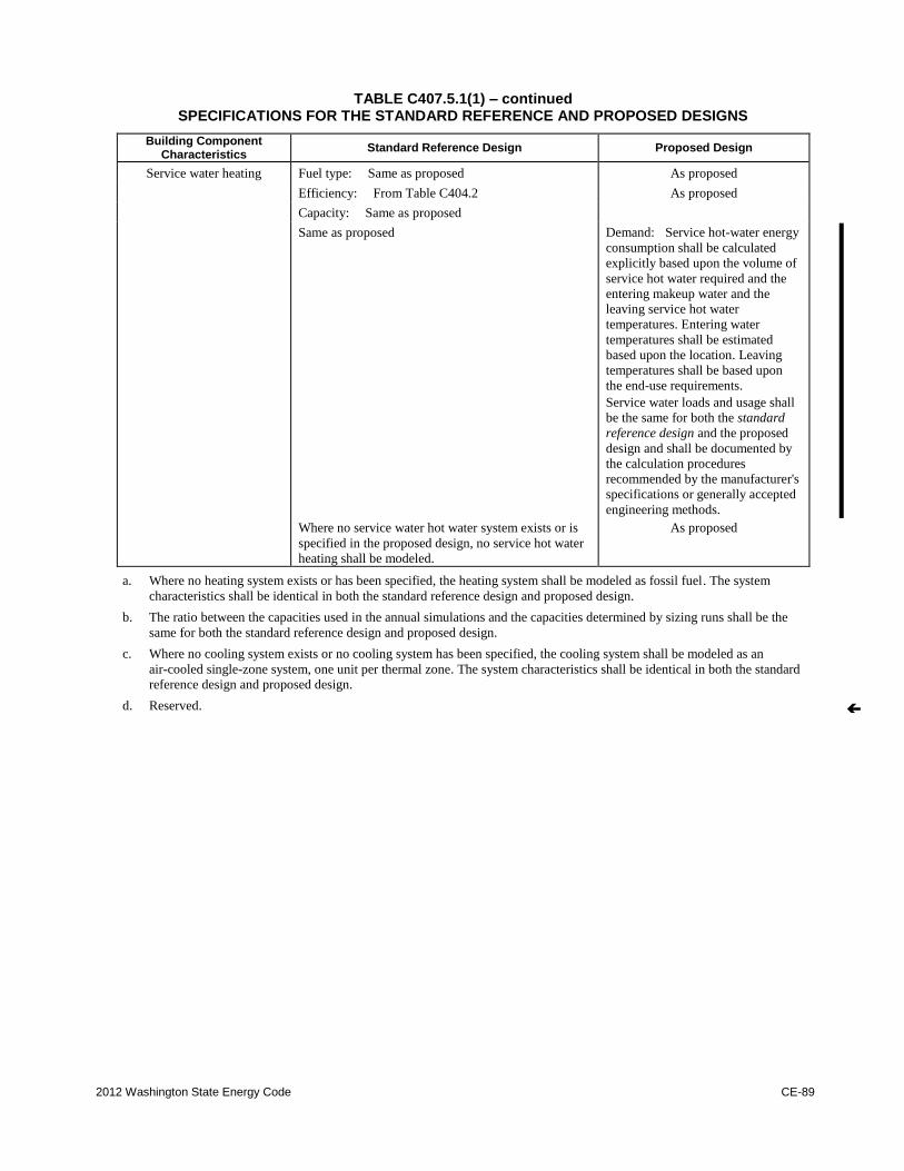
2012 Washington State Energy Code CE-89
TABLE C407.5.1(1) – continued SPECIFICATIONS FOR THE STANDARD REFERENCE AND PROPOSED DESIGNS
Building Component Characteristics
Standard Reference Design Proposed Design
Service water heating Fuel type: Same as proposed As proposed
Efficiency: From Table C404.2 As proposed
Capacity: Same as proposed
Same as proposed Demand: Service hot-water energy
consumption shall be calculated
explicitly based upon the volume of
service hot water required and the
entering makeup water and the
leaving service hot water
temperatures. Entering water
temperatures shall be estimated
based upon the location. Leaving
temperatures shall be based upon
the end-use requirements.
Service water loads and usage shall
be the same for both the standard
reference design and the proposed
design and shall be documented by
the calculation procedures
recommended by the manufacturer's
specifications or generally accepted
engineering methods. Where no service water hot water system exists or is
specified in the proposed design, no service hot water
heating shall be modeled.
As proposed
a. Where no heating system exists or has been specified, the heating system shall be modeled as fossil fuel. The system
characteristics shall be identical in both the standard reference design and proposed design.
b. The ratio between the capacities used in the annual simulations and the capacities determined by sizing runs shall be the
same for both the standard reference design and proposed design.
c. Where no cooling system exists or no cooling system has been specified, the cooling system shall be modeled as an
air-cooled single-zone system, one unit per thermal zone. The system characteristics shall be identical in both the standard
reference design and proposed design.
d. Reserved.
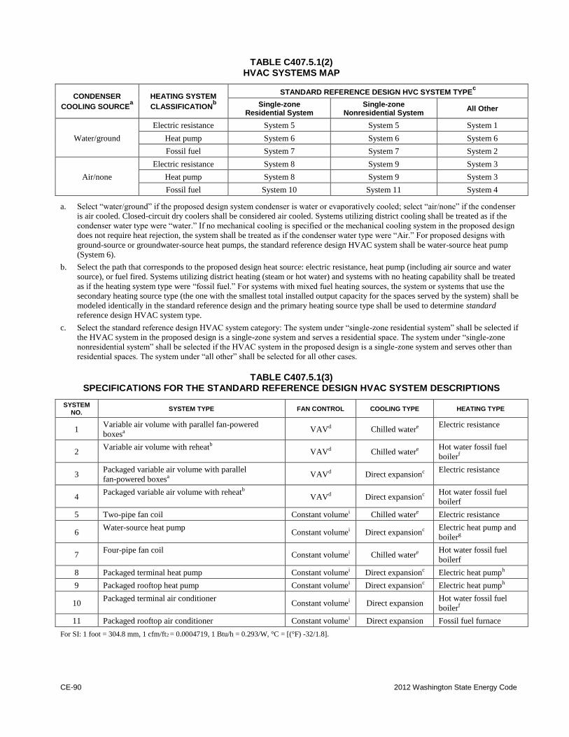
CE-90 2012 Washington State Energy Code
TABLE C407.5.1(2) HVAC SYSTEMS MAP
CONDENSER
COOLING SOURCEa
HEATING SYSTEM
CLASSIFICATIONb
STANDARD REFERENCE DESIGN HVC SYSTEM TYPEc
Single-zone Residential System
Single-zone Nonresidential System
All Other
Water/ground
Electric resistance System 5 System 5 System 1
Heat pump System 6 System 6 System 6
Fossil fuel System 7 System 7 System 2
Air/none
Electric resistance System 8 System 9 System 3
Heat pump System 8 System 9 System 3
Fossil fuel System 10 System 11 System 4
a. Select “water/ground” if the proposed design system condenser is water or evaporatively cooled; select “air/none” if the condenser
is air cooled. Closed-circuit dry coolers shall be considered air cooled. Systems utilizing district cooling shall be treated as if the
condenser water type were “water.” If no mechanical cooling is specified or the mechanical cooling system in the proposed design
does not require heat rejection, the system shall be treated as if the condenser water type were “Air.” For proposed designs with
ground-source or groundwater-source heat pumps, the standard reference design HVAC system shall be water-source heat pump
(System 6).
b. Select the path that corresponds to the proposed design heat source: electric resistance, heat pump (including air source and water
source), or fuel fired. Systems utilizing district heating (steam or hot water) and systems with no heating capability shall be treated
as if the heating system type were “fossil fuel.” For systems with mixed fuel heating sources, the system or systems that use the
secondary heating source type (the one with the smallest total installed output capacity for the spaces served by the system) shall be
modeled identically in the standard reference design and the primary heating source type shall be used to determine standard
reference design HVAC system type.
c. Select the standard reference design HVAC system category: The system under “single-zone residential system” shall be selected if
the HVAC system in the proposed design is a single-zone system and serves a residential space. The system under “single-zone
nonresidential system” shall be selected if the HVAC system in the proposed design is a single-zone system and serves other than
residential spaces. The system under “all other” shall be selected for all other cases.
TABLE C407.5.1(3) SPECIFICATIONS FOR THE STANDARD REFERENCE DESIGN HVAC SYSTEM DESCRIPTIONS
SYSTEM NO.
SYSTEM TYPE FAN CONTROL COOLING TYPE HEATING TYPE
1 Variable air volume with parallel fan-powered
boxesa VAVd Chilled watere
Electric resistance
2 Variable air volume with reheatb
VAVd Chilled watere Hot water fossil fuel
boilerf
3 Packaged variable air volume with parallel
fan-powered boxesa VAVd Direct expansionc
Electric resistance
4 Packaged variable air volume with reheatb
VAVd Direct expansionc Hot water fossil fuel
boilerf
5 Two-pipe fan coil Constant volumei Chilled watere Electric resistance
6 Water-source heat pump
Constant volumei Direct expansionc Electric heat pump and
boilerg
7 Four-pipe fan coil
Constant volumei Chilled watere Hot water fossil fuel
boilerf
8 Packaged terminal heat pump Constant volumei Direct expansionc Electric heat pumph
9 Packaged rooftop heat pump Constant volumei Direct expansionc Electric heat pumph
10 Packaged terminal air conditioner
Constant volumei Direct expansion Hot water fossil fuel
boilerf
11 Packaged rooftop air conditioner Constant volumei Direct expansion Fossil fuel furnace
For SI: 1 foot = 304.8 mm, 1 cfm/ft2 = 0.0004719, 1 Btu/h = 0.293/W, °C = [(°F) -32/1.8].
2012 Washington State Energy Code CE-91
a. VAV with parallel boxes: Fans in parallel VAV fan-powered boxes shall be sized for 50 percent of the peak design flow rate and shall be
modeled with 0.35 W/cfm fan power. Minimum volume setpoints for fan-powered boxes shall be equal to the minimum rate for the space
required for ventilation consistent with Section C403.4.5, Exception 5. Supply air temperature setpoint shall be constant at the design condition.
b. VAV with reheat: Minimum volume setpoints for VAV reheat boxes shall be 0.4 cfm/ft2 of floor area. Supply air temperature shall be reset
based on zone demand from the design temperature difference to a 10°F temperature difference under minimum load conditions. Design
airflow rates shall be sized for the reset supply air temperature, i.e., a 10°F temperature difference.
c. Direct expansion: The fuel type for the cooling system shall match that of the cooling system in the proposed design.
d. VAV: When the proposed design system has a supply, return or relief fan motor horsepower (hp) requiring variable flow controls as required
by Section C403.2.12, the corresponding fan in the VAV system of the standard reference design shall be modeled assuming a variable speed drive. For smaller fans, a forward-curved centrifugal fan with inlet vanes shall be modeled. If the proposed design's system has a direct digital
control system at the zone level, static pressure setpoint reset based on zone requirements in accordance with Section C403.4.2 shall be
modeled.
e. Chilled water: For systems using purchased chilled water, the chillers are not explicitly modeled. Otherwise, the standard reference design's
chiller plant shall be modeled with chillers having the number as indicated in Table C407.5.1(4) as a function of standard reference building
chiller plant load and type as indicated in Table C407.5.1(5) as a function of individual chiller load. Where chiller fuel source is mixed, the
system in the standard reference design shall have chillers with the same fuel types and with capacities having the same proportional capacity as the proposed design's chillers for each fuel type. Chilled water supply temperature shall be modeled at 44°F design supply temperature and
56°F return temperature. Piping losses shall not be modeled in either building model. Chilled water supply water temperature shall be reset in
accordance with Section C403.4.3.4. Pump system power for each pumping system shall be the same as the proposed design; if the proposed design has no chilled water pumps, the standard reference design pump power shall be 22 W/gpm (equal to a pump operating against a 75-foot
head, 65-percent combined impeller and motor efficiency). The chilled water system shall be modeled as primary-only variable flow with flow
maintained at the design rate through each chiller using a bypass. Chilled water pumps shall be modeled as riding the pump curve or with variable-speed drives when required in Section C403.4.3.4. The heat rejection device shall be an axial fan cooling tower with variable speed
fans if required in Section C403.4.4 or Section C403.2.12. Condenser water design supply temperature shall be 85°F or 10°F approach to
design wet-bulb temperature, whichever is lower, with a design temperature rise of 10°F. The tower shall be controlled to maintain a 70°F leaving water temperature where weather permits, floating up to leaving water temperature at design conditions. Pump system power for each
pumping system shall be the same as the proposed design; if the proposed design has no condenser water pumps, the standard reference design pump power shall be 19 W/gpm (equal to a pump operating against a 60-foot head, 60-percent combined impeller and motor efficiency). Each
chiller shall be modeled with separate condenser water and chilled water pumps interlocked to operate with the associated chiller.
f. Fossil fuel boiler: For systems using purchased hot water or steam, the boilers are not explicitly modeled. Otherwise, the boiler plant shall
use the same fuel as the proposed design and shall be natural draft. The standard reference design boiler plant shall be modeled with a single boiler if the standard reference design plant load is 600,000 Btu/h and less and with two equally sized boilers for plant capacities exceeding
600,000 Btu/h. Boilers shall be staged as required by the load. Hot water supply temperature shall be modeled at 180°F design supply
temperature and 130°F return temperature. Piping losses shall not be modeled in either building model. Hot water supply water temperature shall be reset in accordance with Section C403.4.3.4. Pump system power for each pumping system shall be the same as the proposed design; if
the proposed design has no hot water pumps, the standard reference design pump power shall be 19 W/gpm (equal to a pump operating against
a 60-foot head, 60-percent combined impeller and motor efficiency). The hot water system shall be modeled as primary only with continuous variable flow. Hot water pumps shall be modeled as riding the pump curve or with variable speed drives when required by Section C403.4.3.4.
g. Electric heat pump and boiler: Water-source heat pumps shall be connected to a common heat pump water loop controlled to maintain
temperatures between 60°F and 90°F. Heat rejection from the loop shall be provided by an axial fan closed-circuit evaporative fluid cooler with
variable speed fans if required in Section C403.4.2 or Section C403.2.12. Heat addition to the loop shall be provided by a boiler that uses the same fuel as the proposed design and shall be natural draft. If no boilers exist in the proposed design, the standard reference building boilers
shall be fossil fuel. The standard reference design boiler plant shall be modeled with a single boiler if the standard reference design plant load is
600,000 Btu/h or less and with two equally sized boilers for plant capacities exceeding 600,000 Btu/h. Boilers shall be staged as required by the load. Piping losses shall not be modeled in either building model. Pump system power shall be the same as the proposed design; if the proposed
design has no pumps, the standard reference design pump power shall be 22 W/gpm, which is equal to a pump operating against a 75-foot head,
with a 65-percent combined impeller and motor efficiency. Loop flow shall be variable with flow shutoff at each heat pump when its compressor cycles off as required by Section C403.4.3.3. Loop pumps shall be modeled as riding the pump curve or with variable speed drives
when required by Section C403.4.3.4.
h. Electric heat pump: Electric air-source heat pumps shall be modeled with electric auxiliary heat. The system shall be controlled with a
multistage space thermostat and an outdoor air thermostat wired to energize auxiliary heat only on the last thermostat stage and when outdoor air temperature is less than 40°F. In heating operation the system shall be controlled to operate the heat pump as the first stage of heating,
before energizing the electric auxiliary heat, down to a minimum outdoor air temperature of 35°F for System No. 8 or 17°F for System No. 9. If
the Proposed Design utilizes the same system type as the Standard Design (PTHP or PSZ-HP), the Proposed Design shall be modeled with the
same minimum outdoor air temperature for heat pump operation as the Standard Design. For temperatures below the stated minimum outdoor
air temperatures, the electric auxiliary heat shall be controlled to provide the full heating load.
i. Constant volume: Fans shall be controlled in the same manner as in the proposed design; i.e., fan operation whenever the space is occupied
or fan operation cycled on calls for heating and cooling. If the fan is modeled as cycling and the fan energy is included in the energy efficiency rating of the equipment, fan energy shall not be modeled explicitly.
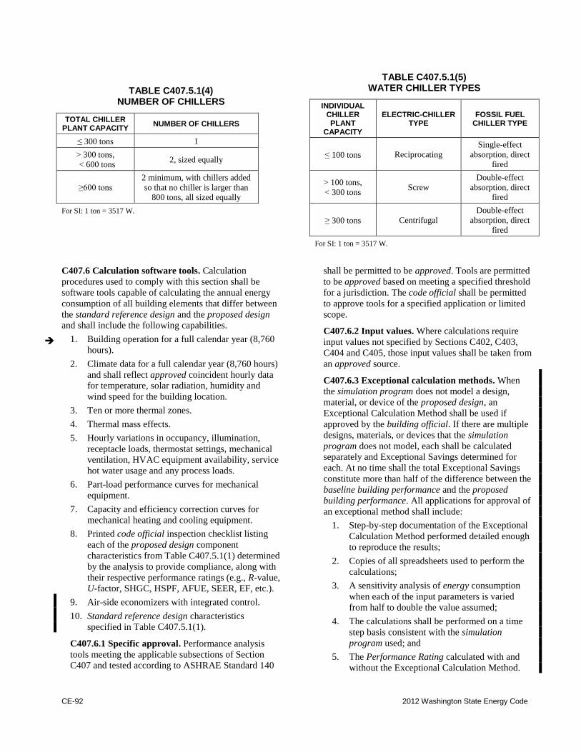
CE-92 2012 Washington State Energy Code
TABLE C407.5.1(4) NUMBER OF CHILLERS
TOTAL CHILLER PLANT CAPACITY
NUMBER OF CHILLERS
≤300 tons 1
> 300 tons,
< 600 tons 2, sized equally
≥600 tons
2 minimum, with chillers added
so that no chiller is larger than
800 tons, all sized equally
For SI: 1 ton = 3517 W.
TABLE C407.5.1(5) WATER CHILLER TYPES
INDIVIDUAL CHILLER PLANT
CAPACITY
ELECTRIC-CHILLER TYPE
FOSSIL FUEL CHILLER TYPE
≤100 tons Reciprocating
Single-effect
absorption, direct
fired
> 100 tons,
< 300 tons Screw
Double-effect
absorption, direct
fired
≥300 tons Centrifugal
Double-effect
absorption, direct
fired
For SI: 1 ton = 3517 W.
C407.6 Calculation software tools. Calculation
procedures used to comply with this section shall be
software tools capable of calculating the annual energy
consumption of all building elements that differ between
the standard reference design and the proposed design
and shall include the following capabilities.
1. Building operation for a full calendar year (8,760
hours).
2. Climate data for a full calendar year (8,760 hours)
and shall reflect approved coincident hourly data
for temperature, solar radiation, humidity and
wind speed for the building location.
3. Ten or more thermal zones.
4. Thermal mass effects.
5. Hourly variations in occupancy, illumination,
receptacle loads, thermostat settings, mechanical
ventilation, HVAC equipment availability, service
hot water usage and any process loads.
6. Part-load performance curves for mechanical
equipment.
7. Capacity and efficiency correction curves for
mechanical heating and cooling equipment.
8. Printed code official inspection checklist listing
each of the proposed design component
characteristics from Table C407.5.1(1) determined
by the analysis to provide compliance, along with
their respective performance ratings (e.g., R-value,
U-factor, SHGC, HSPF, AFUE, SEER, EF, etc.).
9. Air-side economizers with integrated control.
10. Standard reference design characteristics
specified in Table C407.5.1(1).
C407.6.1 Specific approval. Performance analysis
tools meeting the applicable subsections of Section
C407 and tested according to ASHRAE Standard 140
shall be permitted to be approved. Tools are permitted
to be approved based on meeting a specified threshold
for a jurisdiction. The code official shall be permitted
to approve tools for a specified application or limited
scope.
C407.6.2 Input values. Where calculations require
input values not specified by Sections C402, C403,
C404 and C405, those input values shall be taken from
an approved source.
C407.6.3 Exceptional calculation methods. When
the simulation program does not model a design,
material, or device of the proposed design, an
Exceptional Calculation Method shall be used if
approved by the building official. If there are multiple
designs, materials, or devices that the simulation
program does not model, each shall be calculated
separately and Exceptional Savings determined for
each. At no time shall the total Exceptional Savings
constitute more than half of the difference between the
baseline building performance and the proposed
building performance. All applications for approval of
an exceptional method shall include:
1. Step-by-step documentation of the Exceptional
Calculation Method performed detailed enough
to reproduce the results;
2. Copies of all spreadsheets used to perform the
calculations;
3. A sensitivity analysis of energy consumption
when each of the input parameters is varied
from half to double the value assumed;
4. The calculations shall be performed on a time
step basis consistent with the simulation
program used; and
5. The Performance Rating calculated with and
without the Exceptional Calculation Method.
2012 Washington State Energy Code CE-93
SECTION C408 SYSTEM COMMISSIONING
C408.1 General. This section covers the commissioning
of the building mechanical systems in Section C403,
service water heating systems in Section C404, electrical
power and lighting systems in Section C405 and energy
metering in Section C409. Prior to passing the final
mechanical and electrical inspections or obtaining a
certificate of occupancy, the registered design
professional or approved agency shall provide evidence
of systems commissioning and completion in accordance
with the provisions of this section.
Copies of all documentation shall be given to the
owner and made available to the code official upon
request in accordance with Sections C408.1.2 and
C408.1.3.
C408.1.1 Commissioning plan. A commissioning
plan shall be developed by a registered design
professional or approved agency and shall include the
following items:
1. A narrative description of the activities that will
be accomplished during each phase of
commissioning, including the personnel
intended to accomplish each of the activities.
2. Roles and responsibilities of the commissioning
team.
3. A schedule of activities including systems
testing and balancing, functional testing, and
supporting documentation.
4. A listing of the specific equipment, appliances
or systems to be tested and a description of the
tests to be performed.
5. Functions to be tested.
6. Conditions under which the test will be
performed.
7. Measurable criteria for performance.
C408.1.2 Preliminary commissioning report. A
preliminary report of commissioning test procedures
and results shall be completed and certified by the
registered design professional or approved agency and
provided to the building owner. The report shall be
identified as "Preliminary Commissioning Report" and
shall identify:
1. Itemization of deficiencies found during testing
required by this section that have not been
corrected at the time of report preparation.
2. Deferred tests that cannot be performed at the
time of report preparation because of climatic
conditions, with anticipated date of completion.
3. Climatic conditions required for performance of
the deferred tests.
4.
Record of progress and completion of operator
training.
C408.1.2.1 Acceptance of report. Buildings, or
portions thereof, shall not pass the final mechanical
and electrical inspections or obtain a certificate of
occupancy, until such time as the code official has
received a letter of transmittal from the building
owner acknowledging that the building owner has
received the Preliminary Commissioning Report.
Completion of the Commissioning Compliance
Checklist (Figure C408.1.2.1) is deemed to satisfy
this requirement.
C408.1.2.2 Copy of report. The code official shall
be permitted to require that a copy of the
Preliminary Commissioning Report be made
available for review by the code official.
C408.1.3 Documentation requirements. The
construction documents shall specify that the
documents described in this section be provided to the
building owner within 90 days of the date of receipt of
the certificate of occupancy.
C408.1.3.1 Record documents. Construction
documents shall be updated to convey a record of
the alterations to the original design. Such updates
shall include updated mechanical, electrical and
control drawings red-lined, or redrawn if specified,
that show all changes to size, type and locations of
components, equipment and assemblies.
C408.1.3.2 Manuals. An operating and maintenance
manual shall be provided and include all of the
following:
1. Submittal data stating equipment size and
selected options for each piece of equipment
requiring maintenance.
2. Manufacturer's operation manuals and
maintenance manuals for each piece of
equipment requiring maintenance, except
equipment not furnished as part of the project.
Required routine maintenance actions shall be
clearly identified.
3. Name and address of at least one service
agency.
4. Controls system maintenance and calibration
information, including wiring diagrams,
schematics, record documents, and control
sequence descriptions. Desired or
field-determined setpoints shall be
permanently recorded on control drawings at
control devices or, for digital control systems,
in system programming instructions.
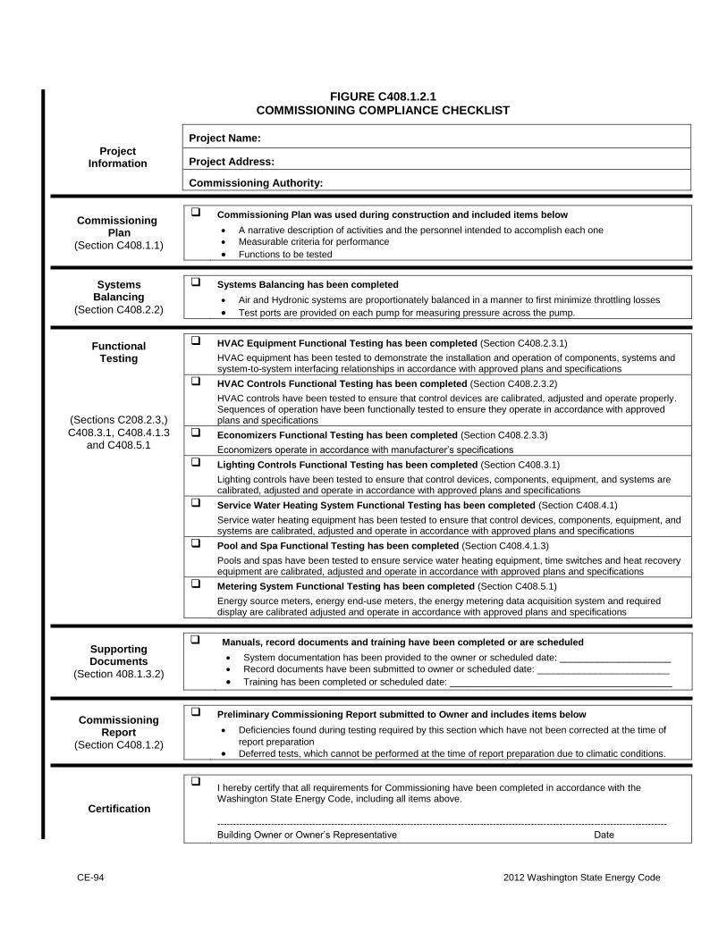
CE-94 2012 Washington State Energy Code
FIGURE C408.1.2.1 COMMISSIONING COMPLIANCE CHECKLIST
Project Information
Project Name:
Project Address:
Commissioning Authority:
Commissioning Plan
(Section C408.1.1)
Commissioning Plan was used during construction and included items below
A narrative description of activities and the personnel intended to accomplish each one
Measurable criteria for performance
Functions to be tested
Systems Balancing
(Section C408.2.2)
Systems Balancing has been completed
Air and Hydronic systems are proportionately balanced in a manner to first minimize throttling losses
Test ports are provided on each pump for measuring pressure across the pump.
Functional Testing
HVAC Equipment Functional Testing has been completed (Section C408.2.3.1)
HVAC equipment has been tested to demonstrate the installation and operation of components, systems and system-to-system interfacing relationships in accordance with approved plans and specifications
(Sections C208.2.3,)
HVAC Controls Functional Testing has been completed (Section C408.2.3.2)
HVAC controls have been tested to ensure that control devices are calibrated, adjusted and operate properly. Sequences of operation have been functionally tested to ensure they operate in accordance with approved plans and specifications
C408.3.1, C408.4.1.3 and C408.5.1
Economizers Functional Testing has been completed (Section C408.2.3.3)
Economizers operate in accordance with manufacturer’s specifications
Lighting Controls Functional Testing has been completed (Section C408.3.1)
Lighting controls have been tested to ensure that control devices, components, equipment, and systems are calibrated, adjusted and operate in accordance with approved plans and specifications
Service Water Heating System Functional Testing has been completed (Section C408.4.1)
Service water heating equipment has been tested to ensure that control devices, components, equipment, and systems are calibrated, adjusted and operate in accordance with approved plans and specifications
Pool and Spa Functional Testing has been completed (Section C408.4.1.3)
Pools and spas have been tested to ensure service water heating equipment, time switches and heat recovery equipment are calibrated, adjusted and operate in accordance with approved plans and specifications
Metering System Functional Testing has been completed (Section C408.5.1)
Energy source meters, energy end-use meters, the energy metering data acquisition system and required display are calibrated adjusted and operate in accordance with approved plans and specifications
Supporting Documents
(Section 408.1.3.2)
Manuals, record documents and training have been completed or are scheduled
System documentation has been provided to the owner or scheduled date: _____________________
Record documents have been submitted to owner or scheduled date: _________________________
Training has been completed or scheduled date: __________________________________________
Commissioning Report
(Section C408.1.2)
Preliminary Commissioning Report submitted to Owner and includes items below
Deficiencies found during testing required by this section which have not been corrected at the time of
report preparation
Deferred tests, which cannot be performed at the time of report preparation due to climatic conditions.
Certification
I hereby certify that all requirements for Commissioning have been completed in accordance with the Washington State Energy Code, including all items above.
---------------------------------------------------------------------------------------------------------------------------------------------- Building Owner or Owner’s Representative Date
2012 Washington State Energy Code CE-95
5. A narrative of how each system is intended to
operate, including recommended setpoints.
Sequence of operation is not acceptable for
this requirement.
C408.1.3.3 System balancing report. A written
report describing the activities and measurements
completed in accordance with Section C408.2.2.
C408.1.3.4 Final commissioning report. A report
of test procedures and results identified as "Final
Commissioning Report" shall be delivered to the
building owner and shall include:
1. Results of functional performance tests.
2. Disposition of deficiencies found during
testing, including details of corrective
measures used or proposed.
3. Functional performance test procedures used
during the commissioning process including
measurable criteria for test acceptance,
provided herein for repeatability.
Exception: Deferred tests which cannot be
performed at the time of report preparation due to
climatic conditions.
C408.1.4 Systems operation training. Training of the
maintenance staff for equipment included in the
manuals required by Section C408.1.3.2 shall include
at a minimum:
1. Review of systems documentation.
2. Hands-on demonstration of all normal
maintenance procedures, normal operating
modes, and all emergency shutdown and
start-up procedures.
3. Training completion report.
C408.2 Mechanical systems commissioning and
completion requirements. Mechanical equipment and
controls shall comply with Section C408.2.
Construction document notes shall clearly indicate
provisions for commissioning and completion
requirements in accordance with this section and are
permitted to refer to specifications for further
requirements.
Exception: Systems which (a) qualify as simple
systems using the criteria in Section C403.3, (b) are
not required to have an economizer per Section
C403.3.1, and (c) where the building total mechanical
equipment capacity is less than 480,000 Btu/h
(140,690 W) cooling capacity and 600,000 Btu/h
(175,860 W) heating capacity.
C408.2.1 Reserved.
C408.2.2 Systems adjusting and balancing. HVAC
systems shall be balanced in accordance with generally
accepted engineering standards. Air and water flow
rates shall be measured and adjusted to deliver final
flow rates within the tolerances provided in the
product specifications. Test and balance activities shall
include air system and hydronic system balancing.
C408.2.2.1 Air systems balancing. Each supply air
outlet and zone terminal device shall be equipped
with means for air balancing in accordance with the
requirements of Chapter 6 of the International
Mechanical Code. Discharge dampers are prohibited
on constant volume fans and variable volume fans
with motors 10 hp (18.6 kW) and larger. Air systems
shall be balanced in a manner to first minimize
throttling losses then, for fans with system power of
greater than 1 hp (0.74 kW), fan speed shall be
adjusted to meet design flow conditions.
Exception: Fans with fan motors of 1 hp (0.74
kW) or less.
C408.2.2.2 Hydronic systems balancing.
Individual hydronic heating and cooling coils shall
be equipped with means for balancing and
measuring flow. Hydronic systems shall be
proportionately balanced in a manner to first
minimize throttling losses, then the pump impeller
shall be trimmed or pump speed shall be adjusted to
meet design flow conditions. Each hydronic system
shall have either the capability to measure pressure
across the pump, or test ports at each side of each
pump.
Exceptions:
1. Pumps with pump motors of 5 hp (3.7 kW)
or less.
2. Where throttling results in no greater than
five percent of the nameplate horsepower
draw above that required if the impeller
were trimmed.
C408.2.3 Functional performance testing.
Functional performance testing specified in Sections
C408.2.3.1 through C408.2.3.3 shall be conducted.
Written procedures which clearly describe the
individual systematic test procedures, the expected
systems' response or acceptance criteria for each
procedure, the actual response or findings, and any
pertinent discussion shall be followed. At a minimum,
testing shall affirm operation during actual or
simulated winter and summer design conditions and
during full outside air conditions.
C408.2.3.1 Equipment. Equipment functional
performance testing shall demonstrate the
installation and operation of components, systems,
and system-to-system interfacing relationships in
CE-96 2012 Washington State Energy Code
accordance with approved plans and specifications
such that operation, function, and maintenance
serviceability for each of the commissioned systems
is confirmed. Testing shall include all modes and
sequence of operation, including under full-load,
part-load and the following emergency conditions:
1. All modes as described in the sequence of
operation;
2. Redundant or automatic back-up mode;
3. Performance of alarms; and
4. Mode of operation upon a loss of power and
restoration of power.
C408.2.3.2 Controls. HVAC control systems shall
be tested to document that control devices,
components, equipment, and systems are calibrated,
adjusted and operate in accordance with approved
plans and specifications. Sequences of operation
shall be functionally tested to document they operate
in accordance with approved plans and
specifications.
C408.2.3.3 Economizers. Air economizers shall
undergo a functional test to determine that they
operate in accordance with manufacturer's
specifications.
C408.3 Lighting system functional testing. Controls
for automatic lighting systems shall comply with Section
C408.3.1.
Exception: Lighting systems in buildings where the
total installed lighting load is less than 20kW and less
than 10 kW of lighting is controlled by occupancy
sensors or automatic daylighting controls.
C408.3.1 Functional testing. Testing shall ensure that
control hardware and software are calibrated, adjusted,
programmed and in proper working condition in
accordance with the construction documents and
manufacturer's installation instructions. Written
procedures which clearly describe the individual
systematic test procedures, the expected systems'
response or acceptance criteria for each procedure, the
actual response or findings, and any pertinent
discussion shall be followed. At a minimum, testing
shall affirm operation during normally occupied
daylight conditions. The construction documents shall
state the party who will conduct the required
functional testing.
Where occupant sensors, time switches,
programmable schedule controls, photosensors or
daylighting controls are installed, the following
procedures shall be performed:
1. Confirm that the placement, sensitivity and
time-out adjustments for occupant sensors yield
acceptable performance.
2. Confirm that the time switches and
programmable schedule controls are
programmed to turn the lights off.
3. Confirm that the placement and sensitivity
adjustments for photosensor controls reduce
electric light based on the amount of usable
daylight in the space as specified.
C408.4 Service water heating systems commissioning
and completion requirements. Service water heating
equipment and controls shall comply with Section
C408.4. Construction document notes shall clearly
indicate provisions for commissioning and completion
requirements in accordance with this section and are
permitted to refer to specifications for further
requirements.
Exception: The following systems are exempt from
the commissioning requirements:
1. Service water heating systems in buildings
where the largest service water heating system
capacity is less than 200,000 Btu/h (58,562 W)
and where there are no pools or in-ground
permanently installed spas.
C408.4.1 Functional performance testing.
Functional performance testing specified in Sections
C408.4.1.1 through C408.4.1.3 shall be conducted.
Written procedures which clearly describe the
individual systematic test procedures, the expected
systems' response or acceptance criteria for each
procedure, the actual response or findings, and any
pertinent discussion shall be followed. At a minimum,
testing shall affirm operation with the system under 50
percent water heating load.
C408.4.1.1 Equipment. Equipment functional
performance testing shall demonstrate the
installation and operation of components, systems,
and system-to-system interfacing relationships in
accordance with approved plans and specifications
such that operation, function, and maintenance
serviceability for each of the commissioned systems
is confirmed. Testing shall include all modes and
sequence of operation, including under full-load,
part-load and the following emergency conditions:
1. Redundant or automatic back-up mode;
2. Performance of alarms; and
3. Mode of operation upon a loss of power and
restoration of power.
C408.4.1.2 Controls. Service water heating controls
shall be tested to document that control devices,
components, equipment, and systems are calibrated,
adjusted and operate in accordance with approved
plans and specifications. Sequences of operation
shall be functionally tested to document they operate
in accordance with approved plans and
specifications.
2012 Washington State Energy Code CE-97
C408.4.1.3 Pools and spas. Service water heating
equipment, time switches, and heat recovery
equipment which serve pools and in-ground
permanently installed spas shall undergo a
functional test to determine that they operate in
accordance with manufacturer's specifications.
C408.5 Metering system commissioning. Energy
metering systems required by Section C409 shall comply
with Section C408.5 and be included in the
commissioning process required by Section C408.1.
Construction documents shall clearly indicate provisions
for commissioning in accordance with Section C408 and
are permitted to refer to specifications for further
requirements.
C408.5.1 Functional testing. Functional testing shall
be conducted by following written procedures which
clearly describe the individual systematic test
procedures, the expected systems' response or
acceptance criteria for each procedure, the actual
response or findings, and any pertinent discussion.
Functional testing shall document that energy source
meters, energy end-use meters, the energy metering
data acquisition system, and required energy
consumption display are calibrated, adjusted and
operate in accordance with approved plans and
specifications. At a minimum, testing shall confirm
that:
1. The metering system devices and components
work properly under low and high load
conditions.
2. The metered data is delivered in a format that is
compatible with the data collection system.
3. The energy display is accessible to building
operation and management personnel.
4. The energy display meets code requirements
regarding views required in Section C409.4.3.
The display shows energy data in identical units
(e.g., kWh).
SECTION C409 ENERGY METERING AND
ENERGY CONSUMPTION MANAGEMENT
C409.1 General. Buildings with a gross conditioned
floor area over 50,000 square feet shall comply with
Section C409. Buildings shall be equipped to measure,
monitor, record and display energy consumption data for
each energy source and end use category per the
provisions of this section, to enable effective energy
management.
Exceptions:
1. Tenant spaces within buildings if the tenant
space has its own utility service and utility
meters.
2. Buildings in which there is no gross conditioned
floor area over 25,000 square feet, including
building common area, that is served by its own
utility services and meters.
C409.1.1 Alternate metering methods. Where
approved by the building official, energy use metering
systems may differ from those required by this section,
provided that they are permanently installed and that
the source energy measurement, end use category
energy measurement, data storage and data display
have similar accuracy to and are at least as effective in
communicating actionable energy use information to
the building management and users, as those required
by this section.
C409.1.2 Conversion factor. Any threshold stated in
kW shall include the equivalent BTU/h heating and
cooling capacity of installed equipment at a conversion
factor of 3,412 Btu per kW at 50 percent demand.
C409.2 Energy source metering. Buildings shall have a
meter at each energy source. For each energy supply
source listed in Section C409.2.1 through C409.2.4,
meters shall collect data for the whole building or for
each separately metered portion of the building where
not exempted by the exception to Section C409.1.
Exceptions:
1. Energy source metering is not required where
end use metering for an energy source accounts
for all usage of that energy type within a
building, and the data acquisition system
accurately totals the energy delivered to the
building or separately metered portion of the
building.
2. Solid fuels such as coal, firewood or wood
pellets that are delivered via mobile
transportation do not require metering.
C409.2.1 Electrical energy. This category shall
include all electrical energy supplied to the building
and its associated site, including site lighting, parking,
recreational facilities, and other areas that serve the
building and its occupants.
C409.2.2 Gas and liquid fuel supply energy. This
category shall include all natural gas, fuel oil, propane
and other gas or liquid fuel energy supplied to the
building and site.
CE-98 2012 Washington State Energy Code
C409.2.3 District energy. This category shall include
all net energy extracted from district steam systems,
district chilled water loops, district hot water systems,
or other energy sources serving multiple buildings.
C409.2.4 Site-generated renewable energy. This
category shall include all net energy generated from
on-site solar, wind, geothermal, tidal or other natural
sources.
C409.3 End-use metering. Meters shall be provided to
collect energy use data for each end-use category listed
in Sections C409.3.1 through C409.3.2. These meters
shall collect data for the whole building or for each
separately metered portion of the building where not
exempted by the exception to Section C409.1. Multiple
meters may be used for any end-use category, provided
that the data acquisition system totals all of the energy
used by that category.
Exceptions:
1. HVAC and water heating equipment serving
only an individual dwelling unit does not
require end-use metering.
2. Separate metering is not required for fire
pumps, stairwell pressurization fans or other life
safety systems that operate only during testing
or emergency.
3. End use metering is not required for individual
tenant spaces not exceeding 2,500 square feet in
floor area when a dedicated source meter
meeting the requirements of Section C409.4.1 is
provided for the tenant space.
C409.3.1 HVAC system energy use. This category
shall include all energy including electrical, gas, liquid
fuel, district steam and district chilled water that is
used by boilers, chillers, pumps, fans and other
equipment used to provide space heating, space
cooling, dehumidification and ventilation to the
building, but not including energy that serves process
loads, water heating or miscellaneous loads as defined
in Section C409.3. Multiple HVAC energy sources,
such as gas, electric and steam, are not required to be
summed together.
Exceptions:
1. All 120 volt equipment.
2. 208/120 volt equipment in a building where
the main service is 480/277 volt power.
3. Electrical energy fed through variable
frequency drives that are connected to the
energy metering data acquisition center.
C409.3.2 Water heating energy use. This category
shall include all energy used for heating of domestic
and service hot water, but not energy used for space
heating.
Exception: Water heating energy use less than 50
kW does not require end-use metering.
C409.4 Measurement devices, data acquisition system
and energy display.
C409.4.1 Meters. Meters and other measurement
devices required by this section shall have local
displays or be configured to automatically
communicate energy data to a data acquisition system.
Source meters may be any digital-type meters. Current
sensors or flow meters are allowed for end use
metering, provided that they have an accuracy
of .+/- 5%. All required metering systems and
equipment shall provide at least hourly data that is
fully integrated into the data acquisition and display
system per the requirements of Section C409.
C409.4.2 Data acquisition system. The data
acquisition system shall store the data from the
required meters and other sensing devices for a
minimum of 36 months. For each energy supply and
end use category required by C409.2 and C409.3, it
shall provide real-time energy consumption data and
logged data for any hour, day, month or year.
C409.4.3 Energy display. For each building subject to
Section C409.2 and C409.3, either a readily accessible
and visible display, or a web page or other electronic
document accessible to building management or to a
third-party energy data analysis service shall be
provided in the building accessible by building
operation and management personnel. The display
shall graphically provide the current energy
consumption rate for each whole building energy
source, plus each end use category, as well as the
average and peak values for any day, week or year.
C409.4.4 Commissioning. The entire system shall be
commissioned in accordance with Section C408.5.
Deficiencies found during testing shall be corrected
and retested and the commissioning report shall be
updated to confirm that the entire metering and data
acquisition and display system is fully functional.
C409.5 Metering for existing buildings.
C409.5.1 Existing buildings that were constructed
subject to the requirements of this section. Where
new or replacement systems or equipment are installed
in an existing building that was constructed subject to
the requirements of this section, metering shall be
2012 Washington State Energy Code CE-99
provided for such new or replacement systems or
equipment so that their energy use is included in the
corresponding end-use category defined in Section
C409.2. This includes systems or equipment added in
conjunction with additions or alterations to existing
buildings.
C409.5.1.1 Small existing buildings. Metering and
data acquisition systems shall be provided for
additions over 25,000 square feet in accordance with
the requirements of sections C409.2 and C409.3.
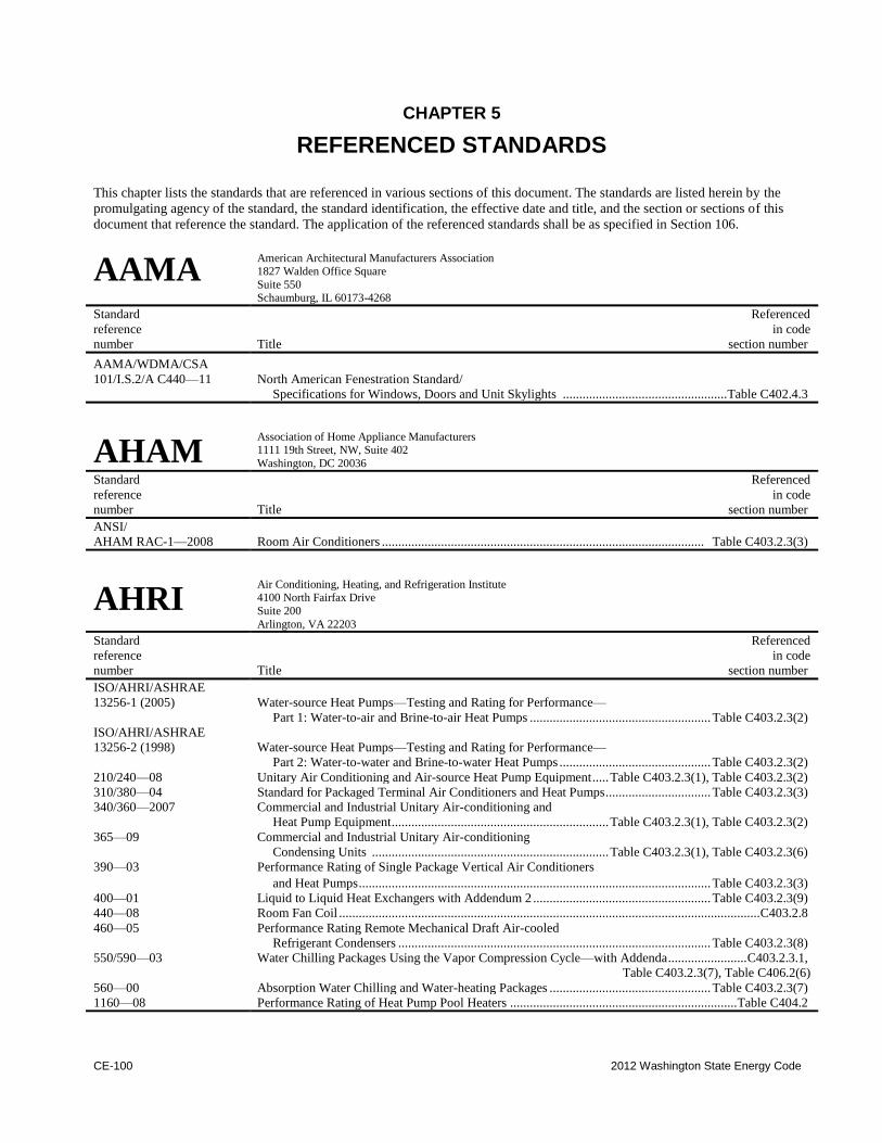
CE-100 2012 Washington State Energy Code
CHAPTER 5
REFERENCED STANDARDS
This chapter lists the standards that are referenced in various sections of this document. The standards are listed herein by the
promulgating agency of the standard, the standard identification, the effective date and title, and the section or sections of this
document that reference the standard. The application of the referenced standards shall be as specified in Section 106.
AAMA American Architectural Manufacturers Association 1827 Walden Office Square
Suite 550 Schaumburg, IL 60173-4268
Standard Referenced
reference in code
number Title section number
AAMA/WDMA/CSA
101/I.S.2/A C440—11 North American Fenestration Standard/
Specifications for Windows, Doors and Unit Skylights .................................................. Table C402.4.3
AHAM Association of Home Appliance Manufacturers 1111 19th Street, NW, Suite 402
Washington, DC 20036
Standard Referenced
reference in code
number Title section number
ANSI/
AHAM RAC-1—2008 Room Air Conditioners .................................................................................................. Table C403.2.3(3)
AHRI Air Conditioning, Heating, and Refrigeration Institute 4100 North Fairfax Drive
Suite 200
Arlington, VA 22203
Standard Referenced
reference in code
number Title section number
ISO/AHRI/ASHRAE
13256-1 (2005) Water-source Heat Pumps—Testing and Rating for Performance—
Part 1: Water-to-air and Brine-to-air Heat Pumps ....................................................... Table C403.2.3(2)
ISO/AHRI/ASHRAE
13256-2 (1998) Water-source Heat Pumps—Testing and Rating for Performance—
Part 2: Water-to-water and Brine-to-water Heat Pumps .............................................. Table C403.2.3(2)
210/240—08 Unitary Air Conditioning and Air-source Heat Pump Equipment ..... Table C403.2.3(1), Table C403.2.3(2)
310/380—04 Standard for Packaged Terminal Air Conditioners and Heat Pumps ................................ Table C403.2.3(3)
340/360—2007 Commercial and Industrial Unitary Air-conditioning and
Heat Pump Equipment .................................................................. Table C403.2.3(1), Table C403.2.3(2)
365—09 Commercial and Industrial Unitary Air-conditioning
Condensing Units ........................................................................ Table C403.2.3(1), Table C403.2.3(6)
390—03 Performance Rating of Single Package Vertical Air Conditioners
and Heat Pumps ........................................................................................................... Table C403.2.3(3)
400—01 Liquid to Liquid Heat Exchangers with Addendum 2 ...................................................... Table C403.2.3(9)
440—08 Room Fan Coil ................................................................................................................................ C403.2.8
460—05 Performance Rating Remote Mechanical Draft Air-cooled
Refrigerant Condensers ............................................................................................... Table C403.2.3(8)
550/590—03 Water Chilling Packages Using the Vapor Compression Cycle—with Addenda ........................ C403.2.3.1,
Table C403.2.3(7), Table C406.2(6)
560—00 Absorption Water Chilling and Water-heating Packages ................................................. Table C403.2.3(7)
1160—08 Performance Rating of Heat Pump Pool Heaters ..................................................................... Table C404.2
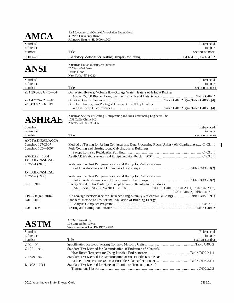
2012 Washington State Energy Code CE-101
AMCA Air Movement and Control Association International
30 West University Drive Arlington Heights, IL 60004-1806
Standard Referenced
reference in code
number Title section number
500D—10 Laboratory Methods for Testing Dampers for Rating ............................................... C402.4.5.1, C402.4.5.2
ANSI American National Standards Institute 25 West 43rd Street
Fourth Floor
New York, NY 10036
Standard Referenced
reference in code
number Title section number
Z21.10.3/CSA 4.3—04 Gas Water Heaters, Volume III—Storage Water Heaters with Input Ratings
Above 75,000 Btu per Hour, Circulating Tank and Instantaneous ...................................... Table C404.2
Z21.47/CSA 2.3—06 Gas-fired Central Furnaces ................................................................... Table C403.2.3(4), Table C406.2.(4)
Z83.8/CSA 2.6—09 Gas Unit Heaters, Gas Packaged Heaters, Gas Utility Heaters
and Gas-fired Duct Furnaces ........................................................... Table C403.2.3(4), Table C406.2.(4)
ASHRAE American Society of Heating, Refrigerating and Air-Conditioning Engineers, Inc. 1791 Tullie Circle, NE
Atlanta, GA 30329-2305
Standard Referenced
reference in code
number Title section number
ANSI/ASHRAE/ACCA
Standard 127-2007 Method of Testing for Rating Computer and Data Processing Room Unitary Air Conditioners ..... C403.4.1
Standard 183—2007 Peak Cooling and Heating Load Calculations in Buildings,
Except Low-rise Residential Buildings ...................................................................................... C403.2.1
ASHRAE—2004 ASHRAE HVAC Systems and Equipment Handbook—2004 ........................................................ C403.2.1
ISO/AHRI/ASHRAE
13256-1 (2005) Water-source Heat Pumps—Testing and Rating for Performance—
Part 1: Water-to-air and Brine-to-air Heat Pumps ........................................................ Table C403.2.3(2)
ISO/AHRI/ASHRAE
13256-2 (1998) Water-source Heat Pumps—Testing and Rating for Performance—
Part 2: Water-to-water and Brine-to-water Heat Pumps ............................................... Table C403.2.3(2)
90.1—2010 Energy Standard for Buildings Except Low-rise Residential Buildings
(ANSI/ASHRAE/IESNA 90.1—2010) ........................... . C401.2, C401.2.1, C402.1.1, Table C402.1.2,
Table C402.2, Table C407.6.1
119—88 (RA 2004) Air Leakage Performance for Detached Single-family Residential Buildings .................. Table C405.5.2(1)
140—2010 Standard Method of Test for the Evaluation of Building Energy
Analysis Computer Programs ..................................................................................................... C407.6.1
146—2006 Testing and Rating Pool Heaters .............................................................................................. Table C404.2
ASTM ASTM International
100 Barr Harbor Drive
West Conshohocken, PA 19428-2859
Standard Referenced
reference in code
number Title section number
C 90—08 Specification for Load-bearing Concrete Masonry Units ......................................................... Table C402.2
C 1371—04 Standard Test Method for Determination of Emittance of Materials
Near Room Temperature Using Portable Emissometers ................................................ Table C402.2.1.1
C 1549—04 Standard Test Method for Determination of Solar Reflectance Near
Ambient Temperature Using A Portable Solar Reflectometer ....................................... Table C405.2.1.1
D 1003—07e1 Standard Test Method for Haze and Luminous Transmittance of
Transparent Plastics ................................................................................................................. C402.3.2.2
CE-102 2012 Washington State Energy Code
ASTM – continued
E 283—04 Test Method for Determining the Rate of Air Leakage Through Exterior
Windows, Curtain Walls and Doors Under Specified Pressure
Differences Across the Specimen ........................................................... Table C402.2.1.1, C402.4.1.2.2,
Table C402.4.3, C402.4.4, C402.4.8
E 408—71(2002) Test Methods for Total Normal Emittance of Surfaces Using
Inspection-meter Techniques ......................................................................................... Table C402.2.1.1
E 779—03 Standard Test Method for Determining Air Leakage Rate by Fan Pressurization ..................... C402.4.1.2.3
E 903—96 Standard Test Method Solar Absorptance, Reflectance and
Transmittance of Materials Using Integrating Spheres (Withdrawn 2005) ................... Table C402.2.1.1
E 1677—05 Standard Specification for an Air-retarder (AR) Material or System for
Low-rise Framed Building Walls ......................................................................................... C402.4.1.2.2
E 1918—97 Standard Test Method for Measuring Solar Reflectance of
Horizontal or Low-sloped Surfaces in the Field ............................................................ Table C402.2.1.1
E 1980—(2001) Standard Practice for Calculating Solar Reflectance Index of
Horizontal and Low-sloped Opaque Surfaces ............................................................... Table C402.2.1.1
E 2178—03 Standard Test Method for Air Permanence of Building Materials ............................................ C402.4.1.2.1
E 2357—05 Standard Test Method for Determining Air Leakage of Air Barriers Assemblies ........................ C404.1.2.2
CSA Canadian Standards Association 5060 Spectrum Way
Mississauga, Ontario, Canada L4W 5N6
Standard Referenced
reference in code
number Title ....................................................................................................................................... section number
AAMA/WDMA/CSA
101/I.S.2/A440—11 North American Fenestration Standard/Specification for
CTI Cooling Technology Institute 2611 FM 1960 West, Suite A-101
Houston, TX 77068
Standard Referenced
reference in code
number Title section number
ATC 105 (00) Acceptance Test Code for Water Cooling Tower .............................................................. Table C403.2.3(8)
STD 201—09 Standard for Certification of Water Cooling Towers Thermal Performances ................... Table C403.2.3(8)
DASMA Door and Access Systems Manufacturers Association 1300 Sumner Avenue
Cleveland, OH 44115-2851
Standard Referenced
reference in code
number Title section number
105—92 (R2004) Test Method for Thermal Transmittance and Air Infiltration of Garage Doors..................... Table C402.4.3
DOE U.S. Department of Energy c/o Superintendent of Documents
U.S. Government Printing Office
Washington, DC 20402-9325
Standard Referenced
reference in code
number Title section number
10 CFR, Part 430—1998 Energy Conservation Program for Consumer Products:
Test Procedures and Certification and Enforcement Requirement
for Plumbing Products; and Certification and Enforcement
Requirements for Residential Appliances; Final Rule .................. Table C403.2.3(4), Table C403.2.3(5),
Table C404.2, Table C406.2(4), Table C406.2(5)
2012 Washington State Energy Code CE-103
DOE – continued
10 CFR, Part 430, Subpart
B,
Appendix N—1998 Uniform Test Method for Measuring the Energy Consumption of
Furnaces and Boilers ..................................................................................................................................... C202
10 CFR, Part 431—2004 Energy Efficiency Program for Certain Commercial and Industrial
Equipment: Test Procedures and Efficiency Standards; Final Rules Table C403.2.3(5), Table C406.2(5)
NAECA 87—(88) National Appliance Energy Conservation Act 1987
[(Public Law 100-12 (with Amendments of 1988-P.L. 100-357)] ................. Tables C403.2.3(1), (2), (4)
IAPMO International Association of Plumbing and Mechanical Officials
4755 E. Philadelphia Street
Ontario, CA 91761
Standard Referenced
reference in code
number Title section number
UPC—2012 Uniform Plumbing Code .................................................................................................................. C201.3
ICC International Code Council, Inc. 500 New Jersey Avenue, NW
6th Floor Washington, DC 20001
Standard Referenced
reference in code
number Title section number
IBC—12 International Building Code ................................................................................ C201.3, C303.2, C402.4.4
IFC—12 International Fire Code ...................................................................................................................... C201.3
IFGC—12 International Fuel Gas Code ............................................................................................................... C201.3
IMC—12 International Mechanical Code................................ C403.2.5, C403.2.5.1, C403.2.6, C403.2.7, C403.2.7.1,
C403.2.7.1.1, C403.2.7.1.2, C403.2.7.1.3, C403.4.5, C408.2.2.1
IESNA Illuminating Engineering Society of North America
120 Wall Street, 17th Floor New York, NY 10005-4001
Standard Referenced
reference in code
number Title section number
ANSI/ASHRAE/IESNA
90.1—2010 Energy Standard for Buildings Except Low-rise Residential Buildings ......... . C401.2, C401.2.1, C402.1.1,
Table C402.1.2, Table C402.2, Table C407.6.1
ISO International Organization for Standardization 1, rue de Varembe, Case postale 56, CH-1211
Geneva, Switzerland
Standard Referenced
reference in code
number Title section number
ISO/AHRI/ASHRAE
13256-1 (2005) Water-source Heat Pumps—Testing and Rating for Performance—
Part 1: Water-to-air and Brine-to-air Heat Pumps .................................................................. C403.2.3(2)
ISO/AHRI/ASHRAE
13256-2 (1998) Water-Source Heat Pumps—Testing and Rating for Performance—
Part 2: Water-to-water and Brine-to-water Heat Pumps ......................................................... C403.2.3(2)
CE-104 2012 Washington State Energy Code
NEMA National Electric Manufacturer’s Association
1300 North 17th Street Suite 1753
Rosslyn, VA 22209
Standard Referenced
reference in code
number Title section number
TP-1-2002 Guide for Determining Energy Efficiency for Distribution Transformers ......................................C405.9
NFRC National Fenestration Rating Council, Inc. 6305 Ivy Lane, Suite 140
Greenbelt, MD 20770
Standard Referenced
reference in code
number Title section number
100—2010 Procedure for Determining Fenestration Products U-factors—Second Edition .............C303.1.2, C402.2.1
200—2010 Procedure for Determining Fenestration Product Solar Heat Gain Coefficients
and Visible Transmittance at Normal Incidence—Second Edition ..................................... C303.1.3, C402.3.1.1
400—2010 Procedure for Determining Fenestration Product Air Leakage—Second Edition ................ Table C402.4.3
SMACNA Sheet Metal and Air Conditioning Contractors National Association, Inc.
4021 Lafayette Center Drive
Chantilly, VA 20151-1209
Standard Referenced
reference in code
number Title section number
SMACNA—85 HVAC Air Duct Leakage Test Manual ..................................................................................... C403.2.7.1.3
UL Underwriters Laboratories
333 Pfingsten Road
Northbrook, IL 60062-2096
Standard Referenced
reference in code
number Title section number
727—06 Oil-fired Central Furnaces—with Revisions through April 2010 ......... Table C403.2.3(4), Table C406.2(4)
731—95 Oil-fired Unit Heaters—with Revisions through April 2010 ................ Table C403.2.3(4), Table C406.2(4)
US-FTC United States-Federal Trade Commission
600 Pennsylvania Avenue NW Washington, DC 20580
Standard Referenced
reference in code
number Title section number
CFR Title 16 R-value Rule .................................................................................................................................. C303.1.4
(May 31, 2005)
WDMA Window and Door Manufacturers Association 1400 East Touhy Avenue, Suite 470
Des Plaines, IL 60018
Standard Referenced
reference in code
number Title section number
AAMA/WDMA/CSA
101/I.S.2/A440—11 North American Fenestration Standard/Specification for
Windows, Doors and Unit Skylights ............................................................................... Table C402.4.3
Recommended