Models: WA301, WA361
WALL MOUNTED
PACKAGED
AIR CONDITIONERINSTALLATION
INSTRUCTIONS
Manual No.: 2100-192M
Supersedes: 2100-192L
File: Volume III, Tab 16
Date: 05-13-02
Bard Manufacturing Company
Bryan, Ohio 43506
Since 1914...Moving ahead just as planned.
© Copyright 2002
MIS-656

Contents
i
Tables
Table 1 Electrical Specifications ........................ 2
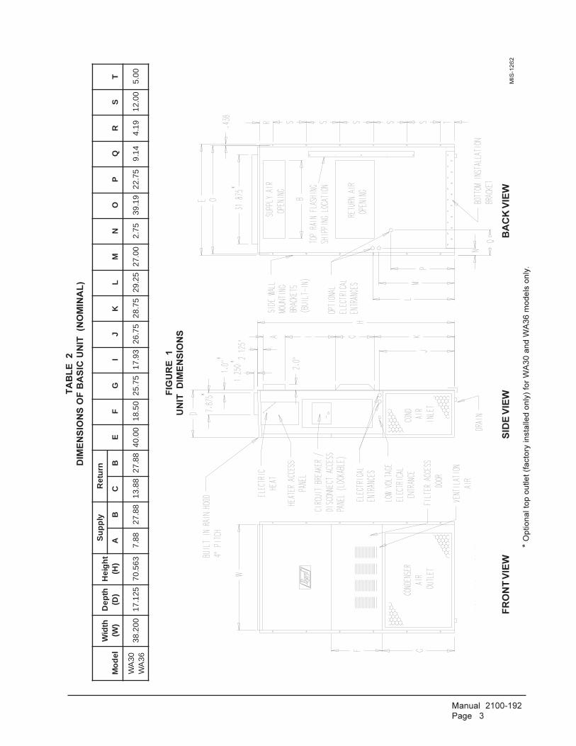
Table 2 Dimensions of Basic Unit ...................... 3
Table 3 Electric Heat Table ................................ 4
Table 4 Operating Voltage Range ..................... 8
Table 5 Thermostat Wire Size ........................... 8
Table 6 Wall Thermostat and
Subbase Combinations ........................ 8
Table 7 Fan Blade Dimensions ....................... 15
Table 8 Suction Line Temperatures ................. 15
Table 9 Indoor Blower Performance ................ 15
Table 10 CFM and ESP..................................... 15
Table 11 Maximum ESP of Operation
Electric Heat Only ............................... 16
Table 12 Cooling Pressure ................................ 16
Table 13 Optional Accessories .......................... 17
Getting Other Information and Publications
For more information,
contact these publishers ........................................ 1
Wall Mount General Information
Air Conditioner Wall Mount Model Nomenclature .. 2
Shipping Damage .................................................. 5
General .................................................................. 5
Duct Work .............................................................. 5
Filters ..................................................................... 5
Fresh Air Intake ...................................................... 6
Condensate Drain .................................................. 6
Installation Instructions
Wall Mounting Information ..................................... 7
Mounting the Unit ................................................... 7
Top Outlet Only ...................................................... 7
Wiring — Main Power ............................................ 7
Wiring — Low Voltage Wiring ................................. 8
Start Up
Important Installer Note ........................................ 13
Crankcase Heaters .............................................. 13
Service Hints ........................................................ 13
Sequence of Operation ........................................ 13
Compressor Control Module ................................ 13
Adjustments ......................................................... 14
Pressure Service Ports ........................................ 14
Troubleshooting
Fan Blade Setting Dimensions ............................ 15
Removal of Fan Shroud ....................................... 15
Refrigerant Charge .............................................. 15
Pressure Table ..................................................... 16
Optional Accessories ........................................... 17
Figures
Figure 1 Unit Dimensions ................................... 3
Figure 2 Blower Damper Assembly ..................... 6
Figure 3 Mounting Instructions ........................... 9
Figure 4 Electric Heat Clearances ...................... 9
Figure 5 Wall-Mounting Instructions ................. 10
Figure 6 Wall-Mounting Instructions ................. 10
Figure 7 Common Wall-Mounting Installations . 11
Figure 8 Low Voltage Wiring ............................. 12
Figure 9 Start Up Label ..................................... 13
Figure 10 Fan Blade Setting ............................... 15

Manual 2100-192
Page 1
Getting Other Information and Publications
These publications can help you install the air
conditioner or heat pump. You can usually find these at
your local library or purchase them directly from the
publisher. Be sure to consult current edition of each
standard.
National Electrical Code ....................... ANSI/NFPA 70
Standard for the Installation ............... ANSI/NFPA 90A
of Air Conditioning and
Ventilating Systems
Standard for Warm Air ........................ANSI/NFPA 90B
Heating and Air
Conditioning Systems
Load Calculation for ............................. ACCA Manual J
Residential Winter and
Summer Air Conditioning
Duct Design for Residential ................ACCA Manual D
Winter and Summer Air
Conditioning and Equipment
Selection
FOR MORE INFORMATION, CONTACTTHESE PUBLISHERS:
ACCA Air Conditioning Contractors of America
1712 New Hampshire Avenue NW
Washington, DC 20009
Telephone: (202) 483-9370
Fax: (202) 234-4721
ANSI American National Standards Institute
11 West Street, 13th Floor
New York, NY 10036
Telephone: (212) 642-4900
Fax: (212) 302-1286
ASHRAE American Society of Heating Refrigerating,
and Air Conditioning Engineers, Inc.
1791 Tullie Circle, N.E.
Atlanta, GA 30329-2305
Telephone: (404) 636-8400
Fax: (404) 321-5478
NFPA National Fire Protection Association
Batterymarch Park
P.O. Box 9101
Quincy, MA 02269-9901
Telephone: (800) 344-3555
Fax: (617) 984-7057
Manufactured under the following U.S. patent numbers:
5,485,878; 5,301,744; 5,002,116;4,924,934; 4,875,520; 4,825,936

Manual 2100-192
Page 2
WALL MOUNT GENERAL INFORMATION
AIR CONDITIONER WALL MOUNT MODEL NOMENCLATURE
WA 36 1 – A 10 X X X X X A
VOLTS & PHASE
A - 230/208/60/1
B - 230/208/60/3
C - 460/60/3
MODEL
NUMBER
REVISIONS
CAPACITY
30 - 2 1/2 Ton
36 - 3 Ton
KW
VENTILATION OPTIONS
X - Barometric Fresh Air
Damper
(Standard)
B - Blank-off Plate
M - Motorized Fresh Air Damper
V - Commercial Room Ventilator
-
Motorized with Exhaust
E - Economizer (Internal - Fully
Modulating with Exhaust
R - Energy Recovery Ventilator -
with Exhaust
FILTER OPTIONS
X - One Inch Throwaway
(Standard)
W- One Inch Washable
P - Two Inch Pleated
COLOR OPTIONS
X - Beige (Standard)
1 - White
2 - Mesa Brown
4 - Buckeye Gray
5 - Desert Brown
6 - Dark Bronze
CONTROL MODULES
COIL OPTIONS
X- Standard
1 - Phenolic Coated Evapora-
tor
2 - Phenolic Coated Con-
denser
3 - Phenolic Coated Evapora-
tor
and Condenser
OUTLET OPTIONS
X - Front (Standard)
T - Top on WA30 and WA36
Models
NOTE: For 0KW and circuit breakers (230/208 Volt) or pull disconnects (460 Volt) applications, insert 0Z in the KW field of
model number.
3
1
2
Maximum size of the time delay fuse or HACR type circuit breaker for protection of field wiring conductors.
Based on 75° copper wire. All wiring must conform to the National Electrical Code and all local codes.
These "Minimum Circuit Ampacity" values are to be used for sizing the field power conductors. Refer to the National Electric
Code (latest revision), Article 310 for power conductor sizing. CAUTION: When more than one field power conductor circuit
is run through one conduit, the conductors must be derated. Pay special attention to note 8 of table 310 regarding
Ampacity Adjustment Factors when more than three conductors are in a raceway.
TABLE 1
ELECTRICAL SPECIFICATIONS
ledoM
detaR&stloVesahP
.oNdleiF
rewoPstiucriC
3
muminiMtiucriCyticapmA
1
mumixaMlanretxE
roesuF.tiucriCrekaerB
2
dleiFrewoP
eriWeziS
2
dnuorGeriWeziS
3
muminiMtiucriCyticapmA
1mumixaMlanretxEroesuF
tiucriCrekaerB
2
dleiFrewoPeziSeriW
2
dnuorGeziSeriW
TKCA
TKCB
TKCA
TKCB
TKCA
TKCB
TKCA
TKCB
Z0A,00A-103AW50A01A51A
1-802/032111
2ro1
42137538
53530609
8864
010101
8
---------
55
---------62
---------06
---------03
---------
4
---------01
---------
8
---------01
Z0B,00B-103AW90B51B
3-802/032111
712305
025305
2188
210101
---------
---------
---------
---------
---------
---------
---------
---------
Z0C,00C-103AW90C51C
3-064111
017162
510203
412101
412101
---------
---------
---------
---------
---------
---------
---------
---------
Z0A,00A-163AW50A01A51A
1-802/032111
2ro1
72137538
53530609
8864
010101
8
---------55
---------62
---------06
---------03
---------
4
---------01
---------
8
---------01
Z0B,00B-163AW90B51B
3-802/032111
022305
525305
0188
010101
---------
---------
---------
---------
---------
---------
---------
---------
Z0C,00C-163AW90C51C
3-064111
017162
510203
412101
412101
---------
---------
---------
---------
---------
---------
---------
---------
Manual 2100-192
Page 3
MIS-1262
FIG
UR
E
1
UN
IT D
IME
NS
ION
S
FR
ON
T V
IEW
BA
CK
VIE
WS
IDE
VIE
W
* O
ptio
na
l to
p o
utle
t (f
acto
ry in
sta
lled
on
ly)
for
WA
30
an
d W
A3
6 m
od
els
on
ly.
TA
BL
E 2
DIM
EN
SIO
NS
OF
BA
SIC
UN
IT (N
OM
INA
L)
ledoM
htdiW
)W(
htpeD
)D(
thgieH
)H(
ylppuSnrute
R
EF
GI
JK
LM
NO
PQ
RS
TA
BC
B
03A
W63
AW
002.83521.71
365.0788.7
88.7288.31
88.7200.04
05.8157.52
39.7157.62
57.8252.92
00.7257.2
91.9357.22
41.991.4
00.2100.5

Manual 2100-192
Page 4
TA
BL
E 3
EL
EC
TR
IC H
EA
T T
AB
LE
sledoM
A-103AW
B-103AW
C-103AW
A-163AW
B-163AW
C-163AW
1-V0421-V802
3-V0423-V802
3-V0641-V042
1-V8023-V042
3-V8023-V064
WK
SPMA
HUT
BSP
MAH
UTB
SPMA
HUT
BSP
MAH
UTB
SPMA
HUT
BSP
MAH
UTB
SPMA
HUT
BSP
MAH
UTB
SPMA
HUT
BSP
MAH
UTB
0.58.02
560,711.81
008,21---
------
------
---8.02
560,711.81
008,21---
------
------
---
0.83.33
003,728.82
574,02---
------
------
---3.33
003,728.82
574,02---
------
------
---
0.016.14
031,432.63
006,52---
------
------
---6.14
031,432.63
006,52---
------
------
---
0.51---
------
------
------
------
---5.26
002,151.45
004,83---
------
------
---
0.6---
------
---4.41
005,025.21
063,512.7
574,02---
------
---4.41
005,025.21
063,512.7
574,02
0.9---
------
---7.12
006,037.81
030,328.01
007,03---
------
---7.12
006,037.81
030,328.01
007,03
0.51---
------
---0.81
002,15---
------
---2.63
004,832.13
004,830.81
002,15

Manual 2100-192
Page 5
SHIPPING DAMAGE
Upon receipt of equipment, the carton should be
checked for external signs of shipping damage. If
damage is found, the receiving party must contact the
last carrier immediately, preferably in writing,
requesting inspection by the carrier’s agent.
GENERAL
The equipment covered in this manual is to be installed
by trained, experienced service and installation
technicians.
The refrigerant system is completely assembled and
charged. All internal wiring is complete.
The unit is designed for use with or without duct work.
Flanges are provided for attaching the supply and return
ducts.
These instructions explain the recommended method to
install the air cooled self-contained unit and the
electrical wiring connections to the unit.
These instructions and any instructions packaged with
any separate equipment required to make up the entire
air conditioning system should be carefully read before
beginning the installation. Note particularly “Starting
Procedure” and any tags and/or labels attached to the
equipment.
While these instructions are intended as a general
recommended guide, they do not supersede any national
and/or local codes in any way. Authorities having
jurisdiction should be consulted before the installation is
made. See Page 1 for information on codes and
standards.
Size of unit for a proposed installation should be based
on heat loss calculation made according to methods of
Air Conditioning Contractors of America (ACCA). The
air duct should be installed in accordance with the
Standards of the National Fire Protection Association
for the Installation of Air Conditioning and Ventilating
Systems of Other Than Residence Type, NFPA No.
90A, and Residence Type Warm Air Heating and Air
Conditioning Systems, NFPA No. 90B. Where local
regulations are at a variance with instructions, installer
should adhere to local codes.
DUCT WORK
All duct work, supply and return, must be properly sized
for the design air flow requirement of the equipment.
Air Conditioning Contractors of America (ACCA) is an
excellent guide to proper sizing. All duct work or
portions thereof not in the conditioned space should be
properly insulated in order to both conserve energy and
prevent condensation or moisture damage.
Any grille that meets the 5/8 inch louver criteria may be
used. It is recommended that Bard Return Air Grille Kit
RG-2 through RG-5 or RFG-2 through RFG-5 be
installed when no return duct is used. Contact
distributor or factory for ordering information. If using
a return air filter grille, filters must be of sufficient size
to allow a maximum velocity of 400 fpm.
FILTERS
A 1 inch throw away filter is suppled with each unit.
The filter slides into position making it easy to service.
This filter can be serviced from the outside by removing
the service door. A 1 inch washable filter and a 2 inch
pleated filter are also available as optional accessories.
The internal filter brackets are adjustable to
accommodate the 2 inch filter by loosening 2 screws in
each bracket assembly and sliding the brackets apart to
the required width and retightening the 4 screws.
Refer to Table 10 for maximum static pressure available
for duct design.
Design the duct work according to methods given by the
Air Conditioning Contractors of America (ACCA).
When duct runs through unheated spaces, it should be
insulated with a minimum of 1 inch of insulation. Use
insulation with a vapor barrier on the outside of the
insulation. Flexible joints should be used to connect the
duct work to the equipment in order to keep the noise
transmission to a minimum.
A 1/4 inch clearance to combustible material for the
first 3 feet of duct attached to the outlet air frame is
required. See Wall Mounting Instructions and Figures 3
and 4 for further details.
Ducts through the walls must be insulated and all joints
taped or sealed to prevent air or moisture entering the
wall cavity.
CAUTIONSome installations may not require any return
air duct. A metallic return air grille is required
with installations not requiring a return air
duct. The spacing between louvers on the
grille shall not be larger than 5/8 inches.

Manual 2100-192
Page 6
The blank-off plate is available upon request from the
factory and is installed in place of the fresh air damper
shipped with each unit.
CONDENSATE DRAIN
A plastic drain hose extends from the drain pan at the
top of the unit down to the unit base. There are openings
in the unit base for the drain hose to pass through. In the
event the drain hose is connected to a drain system of
some type, it must be an open or vented type system to
assure proper drainage.
FRESH AIR INTAKE
All units are built with fresh air inlet slots punched in
the service panel.
If the unit is equipped with the fresh air damper
assembly, the assembly is shipped already attached to
the unit. The damper blade is locked in the closed
position. To allow the damper to operate, the maximum
and minimum blade position stops must be installed.
See Figure 2.
All capacity, efficiency and cost of operation
information as required for Department of Energy
“Energyguide” Fact Sheets is based upon the fresh air
blank-off plate in place and is recommended for
maximum energy efficiency.
FIGURE 2
FRESH AIR DAMPER ASSEMBLY
BLADE IS LOCKED
CLOSED FOR
SHIPPING
MIS-938

Manual 2100-192
Page 7
INSTALLATION INSTRUCTIONS
WARNINGFire hazard can result if 1/4 inch clearance to
combustible materials for supply air duct is not
maintained. See Figure 3.
WALL MOUNTING INFORMATION
1. Two holes, for the supply and return air openings,
must be cut through the wall as shown in Figure 3.
2. On wood-frame walls, the wall construction must be
strong and rigid enough to carry the weight of the unit
without transmitting any unit vibration.
3. Concrete block walls must be thoroughly inspected toinsure that they are capable of carrying the weight ofthe installing unit.
MOUNTING THE UNIT
1. These units are secured by wall mounting brackets
which secure the unit to the outside wall surface at
both sides. A bottom mounting bracket is provided for
ease of installation, but is not required.
2. The unit itself is suitable for “0” inch clearance, but
the supply air duct flange and the first 3 feet of supply
air duct require a minimum of 1/4 inch clearance to
combustible material. If a combustible wall, use a
minimum of 28-1/2" x 8-1/2" dimensions for sizing.
However, it is generally recommended that a 1 inch
clearance is used for ease of installation and
maintaining the required clearance to combustible
material. The supply air opening would then be 30" x
10". See Figures 3 and 4 for details.
3. Locate and mark lag bolt locations and bottom
mounting bracket location. See Figure 3.
4. Mount bottom mounting bracket, if used.
5. Hook top rain flashing under back bend of top. Top
rain flashing is shipped secured to the right side of the
back.
WARNINGFailure to provide the 1/4 inch clearance
between the supply duct and a combustible
surface for the first 3 feet of duct can result in
fire.
6. Position unit in opening and secure with 5/16 lag
bolts; use 7/8 inch diameter flat washers on the lag
bolts.
7. Secure rain flashing to wall and caulk across entire
length of top. See Figure 3.
8. For additional mounting rigidity, the return air and
supply air frames or collars can be drilled and
screwed or welded to the structural wall itself
(depending upon wall construction). Be sure to
observe required clearance if combustible wall.
9. On side by side installations, maintain a minimum of
20 inches clearance on right side to allow access to
heat strips and control panel and to allow proper
airflow to the outdoor coil. Additional clearance may
be required to meet local or national codes.
TOP OUTLET ONLY
1. Remove airframe angles from the back of the unit.
2. Coat angles with two 1/8" beads of silicone as shown.
Silicone is shipped in the control panel. See Figure 6.
3. Secure angles to the top of the unit with 14 screws
provided. Use of prepunched holes provided. Do not
relocate. See Figure 6.
4. After installation duct work, seal around airframe and
duct work to provide a rain tight seal.
5. It is strongly recommended, but not required, that this
unit be installed under a soffit area large enough to
shield the top of the unit. See Figure 7.
WIRING — MAIN POWER
Refer to the unit rating plate for wire sizing information
and maximum fuse or “HACR Type” circuit breaker
size. Each outdoor unit is marked with a “Minimum
Circuit Ampacity”. This means that the field wiring used
must be sized to carry that amount of current. Depending
on the installed KW of electric heat, there may be two
field power circuits required. If this is the case, the unit
serial plate will so indicate. All models are suitable only
for connection with copper wire. Each unit and/or wiring
diagram will be marked “Use Copper Conductors Only”.
These instructions must be adhered to. Refer to the
National Electrical Code (NEC) for complete current
carrying capacity data on the various insulation grades
of wiring material. All wiring must conform to NEC and
all local codes.

Manual 2100-192
Page 8
The electrical data lists fuse and wire sizes (75ºCcopper) for all models, including the most commonlyused heater sizes. Also shown are the number of fieldpower circuits required for the various models withheaters.
The unit rating plate lists a “Maximum Time DelayRelay Fuse” or “HACR Type” circuit breaker that is tobe used with the equipment. The correct size must beused for proper circuit protection and also to assure thatthere will be no nuisance tripping due to the momentaryhigh starting current of the compressor motor.
The disconnect access door on this unit may be locked toprevent unauthorized access to the disconnect. Toconvert for the locking capability, bend the tab located inthe bottom left hand corner of the disconnect openingunder the disconnect access panel straight out. This tabwill now line up with the slot in the door. When shut, apadlock may be placed through the hole in the tabpreventing entry.
TABLE 4
OPERATING VOLTAGE RANGE
NOTE: The voltage should be measured at the
field power connection point in the unit
and while the unit is operating at full load
(maximum amperage operating condition.)
PAT EGNAR
V042 612-352
V802 781-022
Five (5) wires should be run from thermostat subbase to
the 24V terminal board in the unit. A five conductor, 18
gauge copper, color-coded thermostat cable is
recommended. The connection points are shown in
Figure 10.
TABLE 5
THERMOSTAT WIRE SIZE
remrofsnarTAV ALF
eriWeguaG
mumixaMecnatsiDteeFnI
55 3.2
eguag02eguag81eguag61eguag41eguag21
5406001061052
TABLE 6
WALL THERMOSTAT AND SUBBASE COMBINATIONS
tatsomrehT esabbuS serutaeFetanimoderP
200-30481113F78T
300-40480221A935Q
loocegats1,taehegats1no-otua:naFlooc-ffo-taeh:metsyS
140-3048C4308T
--- loocegats1,taehegats1no-otua:naFlooc-ffo-taeh:metsyS
910-30480671C478T
210-40481001A476Q
taehegats2,loocegats1no-otua:naFlooc-otua-taeh:metsyS
120-30484391D478T
210-40481001A476Q
taehegats2,loocegats2no-otua:naFlooc-otua-taeh:metsyS
940-3048083-39F1
--- taehegats2,loocegats2gnimmargorpyad7cinortcelE
340-3048002-MC --- loocegats1,taehegats1
no-otua:naFlooc-ffo-taeh:metsyS
WIRING — LOW VOLTAGE WIRING
230/208V, 1 phase and 3 phase equipment dual primary
voltage transformers. All equipment leaves the factory
wired on 240V tap. For 208V operation, reconnect from
240V to 208V tap. The acceptable operating voltage
range for the 240 and 208V taps are:

Manual 2100-192
Page 9
FIGURE 3
MOUNTING INSTRUCTIONS
NOTE: It is recommended that a bead of silicone caulking be
placed behind the side mounting flanges and under the
top flashing at the time of installation.
Side section view ofsupply air duct for wallmounted unit showing 1/4inch clearance tocombustible surfaces.
FIGURE 4
ELECTRIC HEAT CLEARANCE
MIS-277
WARNING
WARNING
• A minimum of 1/4 inch clearance must be
maintained between the supply air duct and
combustible materials. This is required for
the first 3 feet of ducting.
• It is important to insure that the 1/4 inch
minimum spacing is maintained at all
points.
• Failure to do this could result in overheat-
ing the combustible material and may
result in fire.
MIS-311
4 9/
16

Manual 2100-192
Page 10
FIGURE 5
WALL-MOUNTING INSTRUCTIONS
MIS-549
FIGURE 6
WALL-MOUNTING INSTRUCTIONS
MIS-548
SEE FIGURE 3 – MOUNTING INSTRUCTIONS
SEE UNIT DIMENSIONS, FIGURE 1,
FOR ACTUAL DIMENSIONS
SEE FIGURE 1 FOR
DUCT DIMENSIONS

Manual 2100-192
Page 11
MIS-550
FIGURE 7
COMMON WALL-MOUNTING INSTALLATIONS

Manual 2100-192
Page 12
FIGURE 8
LOW VOLTAGE WIRING
MIS-1373C

Manual 2100-192
Page 13
IMPORTANT INSTALLER NOTE
For improved start-up performance, wash the indoor
coil with a dishwasher detergent.
CRANKCASE HEATERS
All units are provided with some form of compressor
crankcase heat.
All single and three phase models have an insertion
well-type heater located in the lower section of the
compressor housing. This is a self-regulating type
heater that draws only enough power to maintain the
compressor at a safe temperature.
Some form of crankcase heat is essential to prevent
liquid refrigerant from migrating to the compressor,
causing oil pump out on compressor start up and
possible valve failure due to compressing a liquid.
The decal in Figure 9 is affixed to all outdoor units
detailing start up procedure. This is very important.
Please read carefully.
SERVICE HINTS
1. Caution homeowner to maintain clean air filters at all
times. Also, not to needlessly close off supply and
return air registers. This reduces air flow through the
system, which shortens equipment service life as well
as increasing operating costs.
2. Check all power fuses or circuit breakers to be sure
they are the correct rating.
3. Periodic cleaning of the outdoor coil to permit full
and unrestricted airflow circulation is essential.
SEQUENCE OF OPERATION
Cooling—Circuit R-Y makes at thermostat pulling in
compressor contactor, starting the compressor and
outdoor motor. The G (indoor motor) circuit is
automatically completed on any call for cooling
operation or can be energized by manual fan switch on
subbase for constant air circulation. On all 230 volt
units there is a one minute off delay on the blower
motor. 460 volt models do not have an off delay. On a
call for heating, circuit R-W1 make at the thermostat
pulling in heat contact for the strip heat and blower
operation. On a call for second stage heat, R-W2 makes
bringing on second heat contactor, if so equipped.
START UP
FIGURE 9
START UP LABEL
COMPRESSOR CONTROL MODULE
The compressor control module is optional on the
models covered by this manual. The compressor control
is an anti-short cycle/lockout timer with high and low
pressure switch monitoring and alarm relay output.
Adjustable Delay On Make And Break Timer
On initial power up or any time power is interrupted to
the unit the delay on make period begins which will be
2 minutes plus 10% of the delay on break setting. When
the delay on make is complete and the high pressure
switch (and low pressure switch if employed) is closed,
the compressor contactor is energized. Upon shutdown
the delay or break timer starts and prevents restart until
the delay on break and delay on make periods have
expired.
During routine operation of the unit with no power
interruptions the compressor will operate on demand
with no delay.
IMPORTANT
These procedures must be followed
at initial start up and at any time
power has been removed for 12
hours or longer.
To prevent compressor damage which mayresult from the presence of liquid refrigerant inthe compressor crankcase:
1. Make certain the room thermostat is in the"off" position (the compressor is not to operate).
2. Apply power by closing the systemdisconnect switch. This energizes thecompressor heater which evaporates the liquidrefrigerant in the crankcase.
3. Allow 4 hours or 60 minutes per poind ofrefrigerant in the system as noted on the unitrating plate, whichever is greater.
4. After properly elapsed time, the thermostatmay be set to operate the compressor.
5. Except as required for safety while servicing,
do not open system disconnect switch.
7961-061
Manual 2100-192
Page 14
ADJUSTMENTS
Adjustable Delay on Make and Delay on BreakTimer
The potentiometer is used to select Delay on Break time
from 30 seconds to 5 minutes. Delay on Make (DOM)
timing on power-up and after power interruptions is
equal to 2 minutes plus 10% of Delay on Break (DOB)
setting:
0.5 minute (30 seconds) DOB = 123 second DOM
1.0 minute (60 seconds) DOB = 126 second DOM
2.0 minute (120 seconds) DOB = 132 second DOM
3.0 minute (180 seconds) DOB = 138 second DOM
4.0 minute (240 seconds) DOB = 144 second DOM
5.0 minute (300 seconds) DOB = 150 second DOM
During routine operation of the unit with no power
interruptions the compressor will operate on demand
with no delay.
Typical Settings for Dual Unit Installation:
Unit 1: DOB set at 2 minutes, and DOM is 132 seconds
Unit 2: DOB set at 4 minutes, and DOM is 144 seconds
PRESSURE SERVICE PORTS
High and low pressure service ports are installed on all
units so that the system operating pressures can be
observed. Pressure tables can be found later in the
manual covering all models. It is imperative to match
the correct pressure table to the unit by model number.
High Pressure Switch and Lockout Sequence
If the high pressure switch opens, the compressor
contactor will de-energize immediately. The lockout
timer will go into a soft lockout and stay in soft lockout
until the high pressure switch closes and the delay on
break time has expired. If the high pressure switch
opens again in this same operating cycle the unit will go
into manual lockout condition and the alarm relay circuit
will energize. Recycling the wall thermostat resets the
manual lockout.
Low Pressure Switch, Bypass, and LockoutSequence
If the low pressure switch opens for more than 120
seconds, the compressor contactor will de-energize and
go into a soft lockout. Regardless the state of the low
pressure switch, the contactor will reenergize after the
delay on make time delay has expired. If the low
pressure switch remains open, or opens again for longer
than 120 seconds the unit will go into manual lockout
condition and the alarm relay circuit will energize.
Recycling the wall thermostat resets the manual lockout.
Alarm Relay Output
Alarm terminal is output connection for applications
where alarm relay is employed. This terminal is
powered whenever compressor is locked out due to HPC
or LPC sequences as described.
NOTE: Both high and low pressure switch controls are
inherently automatic reset devices. The high
pressure switch and low pressure switch cut
out and cut in settings are fixed by specific air
conditioner or heat pump unit model. The
lockout features, both soft and manual, are a
function of the Compressor Control Module.

Manual 2100-192
Page 15
TROUBLESHOOTING
FAN BLADE SETTING DIMENSIONS
Shown in the drawing below are the correct fan blade
setting dimensions for proper air delivery across the
outdoor coil.
Any service work requiring removal or adjustment in the
fan and/or motor area will require that the dimensions
below be checked and blade adjusted in or out on the
motor shaft accordingly.
REMOVAL OF FAN SHROUD
1. Disconnect all power to unit.
2. Remove the screws holding both grills, one on each
side of unit, and remove grills.
3. Remove screws holding fan shroud to condenser and
bottom – 9 screws.
4. Unwire condenser fan motor.
5. Slide complete motor, fan blade, and shroud assembly
out the left side of the unit.
6. Service motor/fan as needed.
7. Reverse steps to reinstall.
REFRIGERANT CHARGE
The correct system R-22 charge is shown on the unit
rating plate. Optimum unit performance will occur with
a refrigerant charge resulting in a suction line
temperature (6 inches from compressor) as shown in
Table 8.
The suction line temperatures in Table 8 are based upon
80ºF dry bulb/67ºF wet bulb (50 percent R.H.)
temperature and rated airflow across the evaporator
during cooling cycle.
TABLE 9
INDOOR BLOWER PERFORMANCE
CFM AT 230 VOLTS
.P.S.EHnI 2O
163AW,103AW
deepShgiH deepSwoL
lioCyrD lioCteW lioCyrD lioCteW
0. 593,1 513,1 059 539
1. 043,1 072,1 039 519
2. 582,1 091,1 019 588
3. 502,1 001,1 558 038
4. 011,1 000,1 008 557
5. 500,1 078 --- ---
FIGURE 10
FAN BLADE SETTING
TABLE 7
FAN BLADE DIMENSION
ledoM AnoisnemiD
103AW163AW 52.1
TABLE 8
SUCTION LINE TEMPERATURES
ledoMdetaRwolfriA
F°59.pmeTDO
F°28.pmeTDO
103AW 001,1 75-55 66-46
163AW 001,1 95-75 46-26
TABLE 10
RATED CFM AND ESP
1 Rated CFM and ESP on high speed tap
ledoM
1detaR
MFC
1detaR
PSEdednemmoceRegnaRwolfriA
103AW163AW
000,1001,1
04.03.
003,1-039053,1-039

Manual 2100-192
Page 16
TABLE 11
MAXIMUM ESP OF OPERATION
ELECTRIC HEAT ONLY
ledoM teltuOtnorF teltuOpoT
WKwoL
deepShgiHdeepS
woLdeepS
hgiHdeepS
00A50A80A01A51A
05.05.05.54.53.
05.05.05.05.04.
05.54.---53.---
05.05.---05.---
00B60B90B51B
05.04.05.03.
05.05.05.54.
05.---04.---
05.---54.---
00C60C90C51C
05.05.04.53.
05.05.05.54.
05.---04.---
05.---54.---
Low side pressure ± 2 psig
High side pressure ± 5 psig
Tables are based upon rated CFM (airflow) across the evaporator coil and should be
found under section titled "refrigerant charge" elsewhere in manual. If there is any doubt
as to correct charge being in the system, the charge should be removed, system evacu-
ated and recharged to serial plate instructions.
TABLE 12
COOLING PRESSURE – OUTDOOR TEMPERATURE °F
ledoMriAnruteRerutarepmeT erusserP 57 08 58 09 59 001 501 011 511 021 521
103AW
BDged57BWged26
ediSwoLediShgiH
47812
77232
97742
18262
28772
48292
58603
58523
68143
78753
88373
BDged08BWged76
ediSwoLediShgiH
08322
28832
48352
68862
88482
98003
19613
19333
29053
39663
49383
BDged58BWged27
ediSwoLediShgiH
58132
88642
19262
39872
59492
69013
79723
69543
99263
001973
101693
163AW
BDged57BWged26
ediSwoLediShgiH
07422
27242
47952
67572
87092
97403
08613
18823
28933
38153
48363
BDged08BWged76
ediSwoLediShgiH
57922
77842
97562
18272
38792
58113
68523
78733
88843
98063
09373
BDged58BWged27
ediSwoLediShgiH
08832
38752
58572
78292
98703
19223
29633
49943
59063
69373
89683

Manual 2100-192
Page 17
WA301-A
WA301-B
WA301-C
WA361-A
WA361-B
WA361-C
TABLE 13
OPTIONAL ACCESSORIES
LEDOM NOITPIRCSED
50A-30AWHE segakcaPretaeH 1 X X
80A-30AWHE segakcaPretaeH 1 X X
01A-30AWHE egakcaPretaeH s 1 X X
51A-30AWHE egakcaPretaeH s 1 X X
60B-30AWHE segakcaPretaeH 1 X X
90B-30AWHE segakcaPretaeH 1 X X
51B-30AWHE egakcaPretaeH s 1 X X
60C-30AWHE segakcaPretaeH 1 X X
90C-30AWHE egakcaPretaeH s 1 X X
21C-30AWHE segakcaPretaeH 1 X
51C-30AWHE egakcaPretaeH s 1 X X
3-POB etalPffOknalB X X X X X X
3-DAFB repmaDriAhserFcirtemoraB X X X X X X
3-DAFM repmaDriAhserFdezirotoM X X X X X X
3-VRC tsuahxEhtiwrotalitneVlaicremmoC X X X X X X
3-MFIE tsuahxEhtiwrezimonocE X X X X X X
B3A-VREW rotalitneVyrevoceRygrenE X X X X
B3C-VREW rotalitneVyrevoceRygrenE X X
5-AMC )RDT(yaleRyaleDemiT X X X X X X
6-AMC lortnoCtneibmAwoL X X X X
8-AMC CPH+RDT X X X X X X
01-AMC RDT+CPH+CPL X X X X X X
31-AMC CAL+RDT+CPH+CPL X X X X
51-CMC tiKtratS X X
A50-BCMW tiKrekaerBtiucriC X X
B20-BCMW tiKrekaerBtiucriC X
C10-DPMW tiKtcennocsiDlluP X X
B30-BCMW tiKrekaerBtiucriC X
Recommended