W1000Xd1Wide Travel Compact Machining Center
1. NC operability Equipped with a new usability-oriented “CNC-D00 controller”
2. Machining area Wide machining area to accommodate a variety of machining,
such as large workpiece machining and multi-part machining.
3. Productivity Further improves productivity with optimal operation control
achieved through machine/controller integrated development
4. Machining capability Demonstrates a broad range of machining capabilities,
from high-speed, highly efficient machining to heavy-duty machining
5. Environmental performance Creates an earth-friendly plant environment
by greatly reducing power consumption
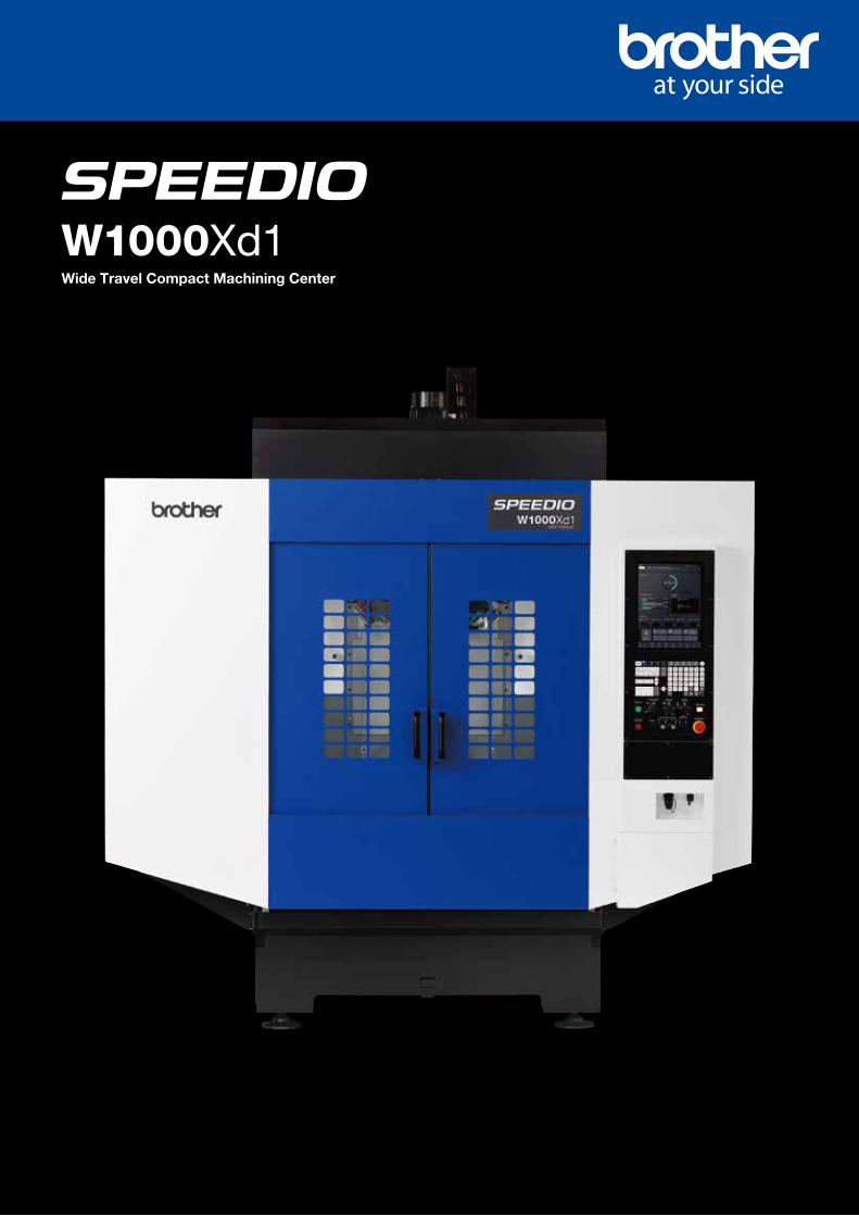
Provides better solutions that eliminate all possible waste, utilizing unparalleled wide travels and maximized high-speed control
In response to customers’ expectations of “machining larger workpieces with #30 machine,”
500 mm travel Y-axis has been achieved despite the compact body, breaking common conceptions of #30 machines.
* The photo shows the machine with 150 mm high column specifications.
Basic specifications
Max. spindle speed (min-1) 10,000 Optional: 10,000 high-torque, 16,000
Travels (mm) X1,000 Y500 Z300
Tool storage capacity (pcs.) 14/21
Rapid traverse rate (m/min) X/Y/Z 50/50/56
Required floor space (mm) 2,410 x 2,443
BT dual contact spindle Optional
Coolant Through Spindle Optional
Times are changing. Are you ready?
You need a machine that's fast and compact.
With the ability to make any cut.
In this world, only the strong survive.
Make it better with SPEEDIO.
CuttingOuttheWaste
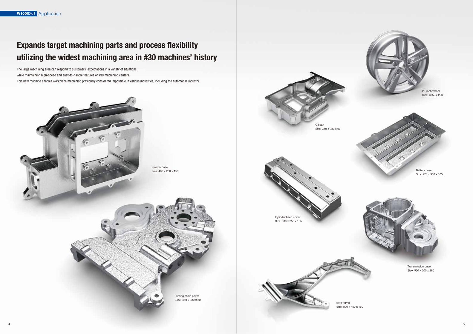
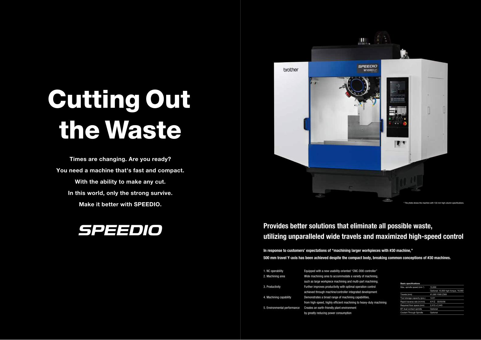
Expands target machining parts and process flexibility utilizing the widest machining area in #30 machines’ history The large machining area can respond to customers’ expectations in a variety of situations,
while maintaining high-speed and easy-to-handle features of #30 machining centers.
This new machine enables workpiece machining previously considered impossible in various industries, including the automobile industry.
Timing chain coverSize: 450 x 330 x 80
20-inch wheelSize: ø350 x 200
54
W1000Xd1 Application
Oil panSize: 380 x 280 x 90
Cylinder head coverSize: 830 x 250 x 135
Inverter caseSize: 400 x 280 x 150
Bike frameSize: 820 x 450 x 160
Battery caseSize: 720 x 350 x 105
Transmission caseSize: 550 x 300 x 280
Network function compatible with peripheral equipment/automation
PLC app
Internal data collection image
External equipment such as PC
ATC tool app Waveform display app
Recovery support app Calculator
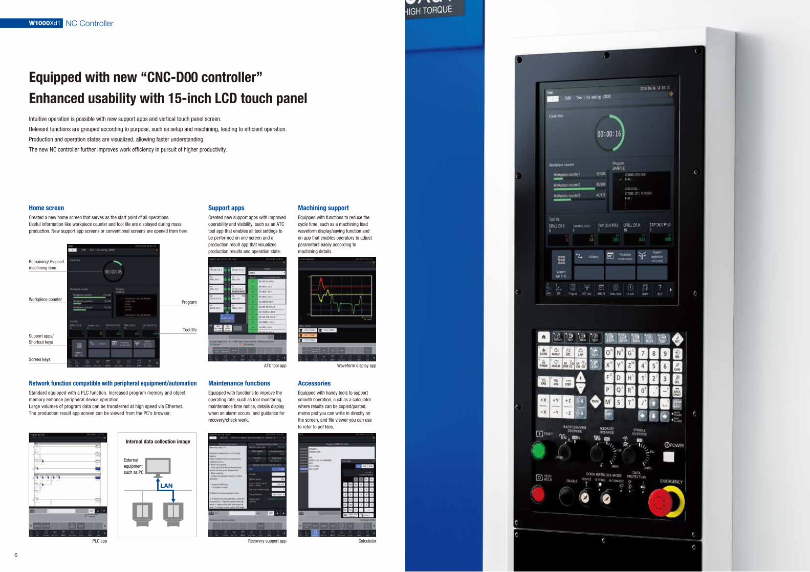
Equipped with new “CNC-D00 controller”Enhanced usability with 15-inch LCD touch panel
Home screenCreated a new home screen that serves as the start point of all operations. Useful information like workpiece counter and tool life are displayed during mass production. New support app screens or conventional screens are opened from here.
Support appsCreated new support apps with improved operability and visibility, such as an ATC tool app that enables all tool settings to be performed on one screen and a production result app that visualizes production results and operation state.
Machining supportEquipped with functions to reduce the cycle time, such as a machining load waveform display/saving function and an app that enables operators to adjust parameters easily according to machining details.
Maintenance functions
LAN
Equipped with functions to improve the operating rate, such as tool monitoring, maintenance time notice, details display when an alarm occurs, and guidance for recovery/check work.
AccessoriesEquipped with handy tools to support smooth operation, such as a calculator where results can be copied/pasted, memo pad you can write in directly on the screen, and file viewer you can use to refer to pdf files.
Standard equipped with a PLC function. Increased program memory and object memory enhance peripheral device operation.Large volumes of program data can be transferred at high speed via Ethernet. The production result app screen can be viewed from the PC’s browser.
Remaining/ Elapsed machining time
Workpiece counter
Support apps/Shortcut keys
Screen keys
Program
Tool life
6
W1000Xd1 NC Controller
Intuitive operation is possible with new support apps and vertical touch panel screen.
Relevant functions are grouped according to purpose, such as setup and machining, leading to efficient operation.
Production and operation states are visualized, allowing faster understanding.
The new NC controller further improves work efficiency in pursuit of higher productivity.

Achieved unprecedented large machining area to accommodate a variety of machining from small to large workpieces
Ample travels and table sizeAmple X/Y-axes travels and sufficient loading capacity allow machining large workpieces and mounting a large jig, not available on conventional #30 machines.
A trunnion jig with a turning diameter of 540 mm can be mounted. (High column 250 mm)
Flexibly applicable to various types of machining
Multi-part machining Door opening dimension: 1,140 mm
Rotary table and flat jig Parallel arrangement of vises From front to table: 226 mm
Large workpiece machining
Making use of the width and depth of the broad jig area, jigs and workpieces can now be placed freely, enabling more flexible and efficient machining in various processes.
Improved workabilityLinked double doors are used. The wide opening and highly accessible table improve workability.
Travels
X 1,000 Y 500
Work area size
X 1,100 Y 500
Max. loading capacity
400 kg
Width 1,100mmDepth 500mm Width 1,100mm
ø540mm
Depth 500mm
X 1,000mmY 500mm
W1000Xd1 Machining Area
8
The wide machining area can accommodate constantly varying onsite needs, such as large
workpiece machining, long-hour multi-part machining of small parts, multi-product small-volume
production with various jigs placed side by side, which enhances the plantwide flexibility.
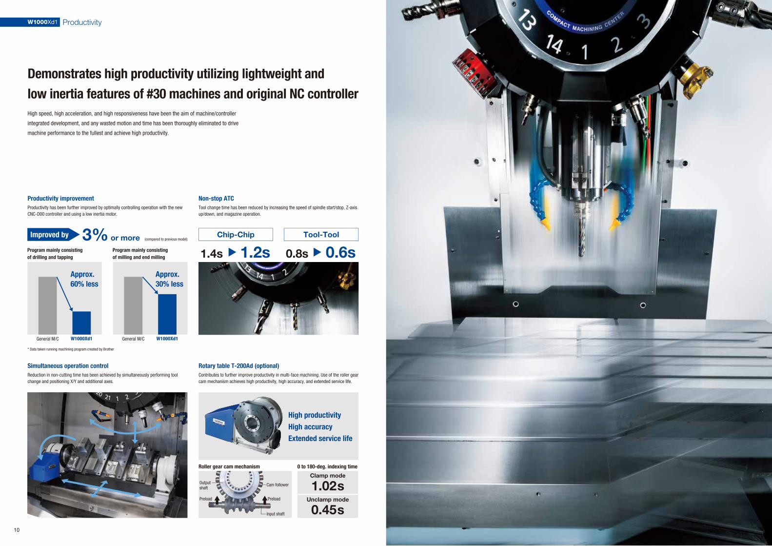
3% or more
W1000Xd1 Productivity
Demonstrates high productivity utilizing lightweight and low inertia features of #30 machines and original NC controller
10
Productivity improvement
Chip-Chip
1.2s1.4s
Tool-Tool
Productivity has been further improved by optimally controlling operation with the new CNC-D00 controller and using a low inertia motor.
Rotary table T-200Ad (optional)Contributes to further improve productivity in multi-face machining. Use of the roller gear cam mechanism achieves high productivity, high accuracy, and extended service life.
Non-stop ATCTool change time has been reduced by increasing the speed of spindle start/stop, Z-axis up/down, and magazine operation.
General M/C
(compared to previous model)
* Data taken running machining program created by Brother
W1000Xd1 General M/C W1000Xd1
Approx. 60% less
Approx. 30% less
Program mainly consisting of milling and end milling
Program mainly consisting of drilling and tapping
Simultaneous operation controlReduction in non-cutting time has been achieved by simultaneously performing tool change and positioning X/Y and additional axes.
Roller gear cam mechanism 0 to 180-deg. indexing time
Improved by
High productivityHigh accuracyExtended service life
Cam followerOutput shaft
Preload Preload
Input shaft
Clamp mode
1.02sUnclamp mode
0.45s
High speed, high acceleration, and high responsiveness have been the aim of machine/controller
integrated development, and any wasted motion and time has been thoroughly eliminated to drive
machine performance to the fullest and achieve high productivity.
0.6s0.8s

The machine is compatible with 7 MPa high-pressure CTS in addition to 1.5 MPa CTS. Demonstrates its abilities in high-speed drilling or peck drilling.
10,000Spindle speed (min-1)
Large hole machiningHole size: ø50 mm / Workpiece: Carbon steelThrow-away drill * High-torque spec.
Taper tappingTapered tap for tubes: PT 1/2Workpiece: Stainless steel * High-torque spec.
End milling (groove)Cutting amount: 430 cc / Workpiece: Carbon steelø16 end mill * High-torque spec.
FacingDepth of cut: ap 3 mm / Workpiece: Carbon steelø80 face mill * High-torque spec.
Provides broad cutting performance from high-speed and highly efficient machining to heavy-duty machining
12
Highly rigid structureStructural parts, such as the base, column, and table, have been specially designed through CAE analysis to secure high rigidity.
Max. tool weight 4 kg
Machining examples
Increased the weight of tools that can be mounted. Combined with wide travels (X 1,000 mm, Y 500 mm), the machine is suitable for a wider variety of applications than ever.
Compatible with 7 MPa high-pressure CTS (optional)
High-power spindle motorA spindle motor with high torque in the medium- and high-speed range is used to achieve high-speed and highly efficient machining. The machine with high-torque spec. (optional) greatly improves the torque in the low-speed range, and demonstrates its abilities in heavy-duty steel machining.
ColumnOptimum rib structure and expanded column width.
Motor torque characteristics
Torque (Nm)
TableExpanded guide span and structure that suppresses deflection
BaseOptimum rib structure and increase in the distance between base plates
ø6 × 170mm (L/D=28)Workpiece: Carbon steel
Spindle motor torque values
High-torque spec.92Nm
40Nm
Standard spec.
High-torque spec. (optional)
Max. torque 92Nm
Max. output 26.2kW
Standard spec.
Max. torque 40Nm
Max. output 18.9kW
W1000Xd1 Machining Capability
* CTS: Coolant Through Spindle
* Changing parameter settings is required. (Tool indexing time is changed.)
High rigidity based on a special design and use of a high-torque spindle motor
achieve stable machining while demonstrating high machining capability.
Machining capability
Drilling
Tool diameter mm(inch) ×Feed mm(inch)/rev
10,000min-1
10,000min-1 high-torque D40 × 0.2 (1.57 x 0.008)D30 × 0.7 (1.18 x 0.03)
D34 × 0.15 (1.34 x 0.006)D26 × 0.4 (1.02 x 0.02)
D25 × 0.1 (0.98 x 0.004)
D30 × 0.15 (1.18 x 0.006)D26 × 0.25 (1.02 x 0.01)
D28 × 0.15 (1.1 x 0.006)D32 × 0.2 (1.26 x 0.008)
Carbon steelCast ironADC
16,000min-1 D18 × 0.1 (0.71 x 0.004)D22 × 0.15 (0.87 x 0.006)D24 × 0.2 (0.94 x 0.008)
Tapping 10,000min-1 M16 × 2.0 (5/8-11UNC)M24 × 3.0 (7/8-9UNC)M27 × 3.0 (1-8UNC)
10,000min-1 high-torque M27 × 3.0 (1-8UNC)M33 × 3.5 (1 1/4-7UNC)M39 × 4.0 (1 1/2-6UNC)
16,000min-1 M14 × 2.0 (1/2-13UNC)M18 × 2.5 (5/8-11UNC)M22 × 2.5 (7/8-9UNC)
Facing
Cutting amountcm3/min (inch3/min)
10,000min-1 100 (6.1)137 (8.4)960 (58.6)
10,000min-1 high-torque 200 (12.2)255 (15.5)1,700 (102.4)
16,000min-1 48 (2.9)73 (4.5)660 (40.3)
Tool diameter mm(inch) ×Pitch mm(inch)
* Data obtained from tests conducted by Brother.

Reliability maintains high productivityEarth-friendly machine
14
High reliability – Measure for chipsChip evacuation performance has been improved to satisfy the wide machining area. Two chip shower pumps are installed to double the flow rate.
Reliability/maintenance functions that prevent defective products and machine failure, and assist quick recovery
Machining load monitoring Maintenance notice Alarm log
To maintain productivity at plants, the machine is equipped with many functions that can prevent possible defects in daily production sites, such as tool abrasion, omission of tool attachment, and re-machining of the same workpiece, and that assist with recovery in the case of machine failure or other problems.
Machining load applied to the spindle is monitored to issue an alarm when the load is not within the preset range.
Energy-saving technologiesLow inertia spindle, highly efficient spindle motor, power regeneration system, energy-saving pump, energy-saving NC functions
Air-saving technologies
Power consumption app
Optimized air blast timing, extremely airtight air purge structure
Notifies operators of maintenance related issues in advance, such as greasing time.
Displays alarm log details to help identify the cause.
High reliability – Improved chip controlClean coolant is returned to a clean tank through a tank with a cyclone filter that removes fine chips. This reduces the filter change frequency and extends the service life of the pump.
High environmental performanceIn addition to the low inertia spindle and highly efficient spindle motor, various energy/air saving technologies are utilized to achieve low power consumption. The amount of power consumption can be viewed on the monitor.
Power consum
ption (kWh/cycle)
Tank with cyclone filter (special option for CTS)
ATC tool monitoringThe presence of a spindle tool is detected before and after tool change without using a sensor.
General M/C
* Data taken running machining program created by Brother
W1000Xd1
Approx. 80% less
Power consumption for one cycle
(1) Dirty coolant
(2) Clean coolant
(3) Drainage
Roof-shape telescopic cover
Image of chip evacuation flow
Tool washing, air assisted type (optional)
W1000Xd1 Reliability and Environmental Performance
Reliability functions that prevent defective products and maintenance functions
that prevent machine failure achieve high reliability and maintain high productivity.
Our efforts to improve environmental performance and effects of high productivity
greatly reduce power consumption, making the machine earth-friendly.
Roof-shape telescopic covers are used for the X/Y-axes to prevent chips from building up.
Discharge pressure and flow rate have been increased to steadily remove chips attached to the holder.
* Depending on the type of coolant, it may have a significant influence on the machine lifecycle. It is recommended to use the coolant which is commercially designated as high lubricity, for example Emulsion type. Especially, the coolant of chemical solution type (ex. Synthetic type) is prohibited to use, because it may cause machine damages.
* When using CTS (Coolant Through Spindle) function, usage of the coolant of combustible type (ex. Oil-based type) is prohibited.
* Windows® is a trademark or registered trademark of Microsoft Corporation in the United States and/or other countries.
Side cover with transparent window (single side, both sides)
16 17
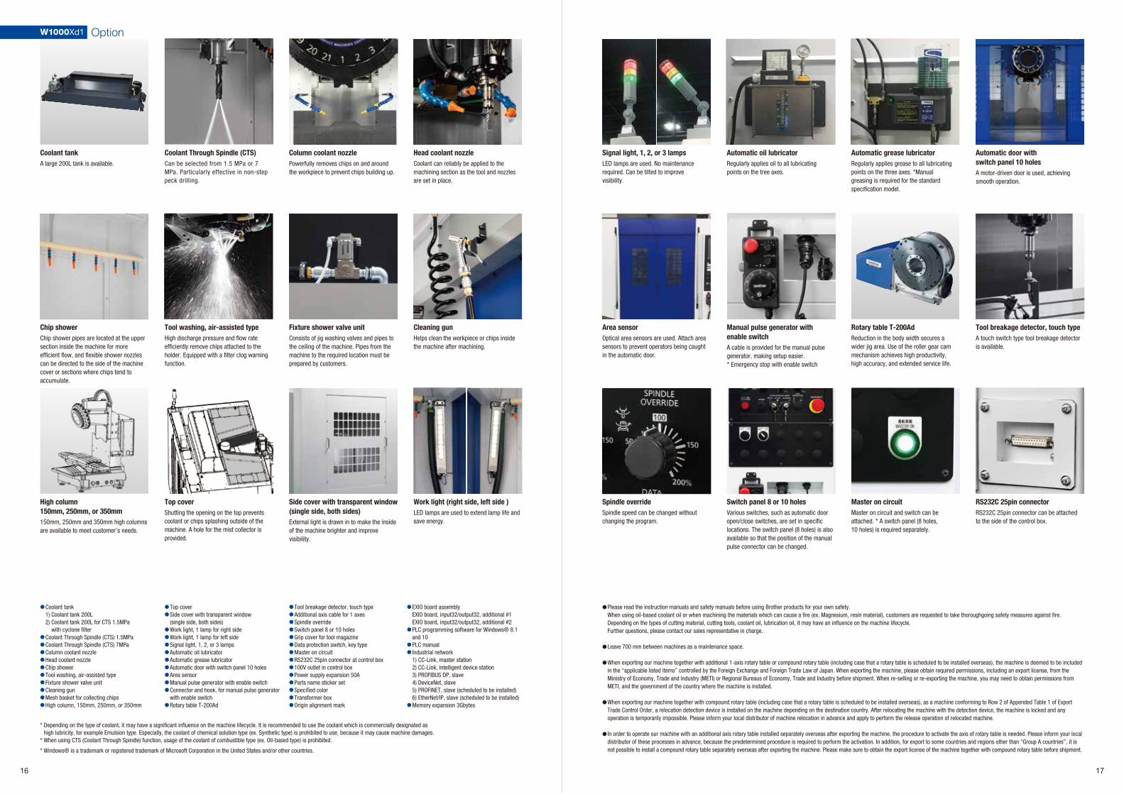
Coolant Through Spindle (CTS) Head coolant nozzleColumn coolant nozzleCoolant tankA large 200L tank is available. Can be selected from 1.5 MPa or 7
MPa. Particularly effective in non-step peck drilling.
Coolant can reliably be applied to the machining section as the tool and nozzles are set in place.
Powerfully removes chips on and around the workpiece to prevent chips building up.
Chip shower Fixture shower valve unit Cleaning gunTool washing, air-assisted typeHigh discharge pressure and flow rate efficiently remove chips attached to the holder. Equipped with a filter clog warning function.
Chip shower pipes are located at the upper section inside the machine for more efficient flow, and flexible shower nozzles can be directed to the side of the machine cover or sections where chips tend to accumulate.
Consists of jig washing valves and pipes to the ceiling of the machine. Pipes from the machine to the required location must be prepared by customers.
Helps clean the workpiece or chips inside the machine after machining.
Top cover Work light (right side, left side )High column 150mm, 250mm, or 350mm150mm, 250mm and 350mm high columns are available to meet customer’s needs.
Shutting the opening on the top prevents coolant or chips splashing outside of the machine. A hole for the mist collector is provided.
External light is drawn in to make the inside of the machine brighter and improve visibility.
LED lamps are used to extend lamp life and save energy.
Automatic oil lubricator Automatic grease lubricator Automatic door with switch panel 10 holes
Signal light, 1, 2, or 3 lampsLED lamps are used. No maintenance required. Can be tilted to improve visibility.
Regularly applies oil to all lubricating points on the tree axes.
Regularly applies grease to all lubricating points on the three axes. *Manual greasing is required for the standard specification model.
Rotary table T-200AdManual pulse generator with enable switch
Tool breakage detector, touch typeArea sensorOptical area sensors are used. Attach area sensors to prevent operators being caught in the automatic door.
Reduction in the body width secures a wider jig area. Use of the roller gear cam mechanism achieves high productivity, high accuracy, and extended service life.
A touch switch type tool breakage detector is available.
Switch panel 8 or 10 holes Master on circuit RS232C 25pin connectorVarious switches, such as automatic door open/close switches, are set in specific locations. The switch panel (8 holes) is also available so that the position of the manual pulse connector can be changed.
Spindle overrideSpindle speed can be changed without changing the program.
Master on circuit and switch can be attached. * A switch panel (8 holes, 10 holes) is required separately.
RS232C 25pin connector can be attached to the side of the control box.
Coolant tank1) Coolant tank 200L2) Coolant tank 200L for CTS 1.5MPa with cyclone filterCoolant Through Spindle (CTS) 1.5MPaCoolant Through Spindle (CTS) 7MPaColumn coolant nozzleHead coolant nozzleChip showerTool washing, air-assisted typeFixture shower valve unitCleaning gunMesh basket for collecting chipsHigh column, 150mm, 250mm, or 350mm
●
●●●●●●●●●●
●●
●●●●●●●●●
●
Top coverSide cover with transparent window (single side, both sides)Work light, 1 lamp for right sideWork light, 1 lamp for left sideSignal light, 1, 2, or 3 lampsAutomatic oil lubricatorAutomatic grease lubricatorAutomatic door with switch panel 10 holesArea sensorManual pulse generator with enable switchConnector and hook, for manual pulse generator with enable switchRotary table T-200Ad
●●●●●●●●●●●●●●
Tool breakage detector, touch typeAdditional axis cable for 1 axesSpindle overrideSwitch panel 8 or 10 holesGrip cover for tool magazineData protection switch, key typeMaster on circuitRS232C 25pin connector at control box100V outlet in control boxPower supply expansion 50AParts name sticker setSpecified colorTransformer boxOrigin alignment mark
●
●
●●
●
EXIO board assemblyEXIO board, input32/output32, additional #1EXIO board, input32/output32, additional #2PLC programming software for Windows® 8.1 and 10PLC manualIndustrial network1) CC-Link, master station2) CC-Link, intelligent device station3) PROFIBUS DP, slave4) DeviceNet, slave5) PROFINET, slave (scheduled to be installed)6) EtherNet/IP, slave (scheduled to be installed)Memory expansion 3Gbytes
A cable is provided for the manual pulse generator, making setup easier.* Emergency stop with enable switch
A motor-driven door is used, achieving smooth operation.
W1000Xd1 Option
Please read the instruction manuals and safety manuals before using Brother products for your own safety.When using oil-based coolant oil or when machining the materials which can cause a fire (ex. Magnesium, resin material), customers are requested to take thoroughgoing safety measures against fire.Depending on the types of cutting material, cutting tools, coolant oil, lubrication oil, it may have an influence on the machine lifecycle.Further questions, please contact our sales representative in charge.
Leave 700 mm between machines as a maintenance space.
When exporting our machine together with additional 1-axis rotary table or compound rotary table (including case that a rotary table is scheduled to be installed overseas), the machine is deemed to be included in the “applicable listed items” controlled by the Foreign Exchange and Foreign Trade Law of Japan. When exporting the machine, please obtain required permissions, including an export license, from the Ministry of Economy, Trade and Industry (METI) or Regional Bureaus of Economy, Trade and Industry before shipment. When re-selling or re-exporting the machine, you may need to obtain permissions from METI, and the government of the country where the machine is installed.
When exporting our machine together with compound rotary table (including case that a rotary table is scheduled to be installed overseas), as a machine conforming to Row 2 of Appended Table 1 of Export Trade Control Order, a relocation detection device is installed on the machine depending on the destination country. After relocating the machine with the detection device, the machine is locked and any operation is temporarily impossible. Please inform your local distributor of machine relocation in advance and apply to perform the release operation of relocated machine.
In order to operate our machine with an additional axis rotary table installed separately overseas after exporting the machine, the procedure to activate the axis of rotary table is needed. Please inform your local distributor of these processes in advance, because the predetermined procedure is required to perform the activation. In addition, for export to some countries and regions other than “Group A countries”, it is not possible to install a compound rotary table separately overseas after exporting the machine. Please make sure to obtain the export license of the machine together with compound rotary table before shipment.
●
●
●
●
●

External Dimensions Machine Specifications
Item W1000Xd1 / W1000Xd1 RD *10
*1 Acceleration must be adjusted for X and Y axes. *2 When using high accuracy mode B. *3 Brother specifications apply to the pull studs for CTS. *4 Actual tool weight differs depending on the configuration and center of gravity. The figures shown here are for reference only. *5 Parameter settings must be changed. (Tool magazine indexing time will change.) *6 Measured in compliance with JIS B6336-9 and MAS011-1987. *7 Spindle motor output differs depemding on the spindle speed. *8 Regular air pressure varies depending on the machine specifications, machining program details, or use of peripheral equipment. Set the pressure higher than the recommended value. *9 Measured in compliance with ISO standards and Brother standards. Please contact your local distributor for details. *10 The machine needs to be equipped with a relocation detection device depending on the destination. Machines equipped with a relocation detection device come with “RD” at the end of the model name.
CNC unit
Table
Spindle
Electric motor
Feed rate
Accuracy *9
Front door
Standard accessories
ATC unit
Tool change time *6
Power source
Machining dimensions
Travels
mm(inch)
mm(inch)
mm(inch)
mm(inch)
mm(inch)
kg(lbs)
min-1
min-1
MPa
m/min(inch/min)
mm/min(inch/min)
pcs.
mm(inch)
mm(inch)
kg(lbs)
sec
sec
kW
kW
kVA
MPa
L/min
mm(inch)
mm(inch)
kg(lbs)
mm(inch)
mm(inch)
X axis
Y axis
Z axis
Distance between table top and spindle nose end
Work area size
Max. loading capacity (uniform load)
Spindle speed
Speed during tapping
Tapered hole
BT dual contact spindle (BIG-PLUS)Coolant through spindle (CTS)
Rapid traverse rate (XYZ-area)
Cutting feed rate
Tool shank type
Pull stud type *3
Tool storage capacity
Max. tool length
Max. tool diameter
Max. tool weight *4
Tool selection method
Tool To Tool
Chip To Chip
Main spindle motor (10min/continuous) *7
Axis feed motor
Power supply
Power capacity (continuous)
Regular air pressure
Required flow
Height
Required floor space [with control unit door open]
Weight
Accuracy of bidirectional axis positioning (ISO230-2:1988)
Repeatability of bidirectional axis positioning (ISO230-2:2014)
Instruction Manual (DVD 1 set), leveling bolts (4 pcs.), leveling plate (4 pcs.)
CNC-D00
1,000 (39.4)
500 (19.7)
300 (11.8)
180~480 (7.1~18.9)
1,100 × 500 (43.3 × 19.7)
300[400 *1] (661[881*1])10,000min-1 specifications:1~10,000, 10,000min-1high-torque specifications (optional):1~10,000,
16,000min-1 specifications (optional):1~16,000
MAX. 6,000
7/24 tapered NO.30
Optional
1.5/7.0: Optional
50 × 50 × 56 (1,969 × 1,969 × 2,205)X,Y,Z:1~30,000(0.04 ~ 1,181) *2
MAS-BT30
MAS-P30T-2
14 / 21
250 (9.8)
ø110 (4.3)
3.0(6.6) [4.0(8.8) *5]/tool, (TOTAL TOOL WEIGHT : 25(55.1)for 14 tools, 35(77.2)for 21 tools)Random shortcut method
0.6
1.2
10,000min-1 specifications: 10.0/6.9, 10,000min-1high-torque specifications (optional): 12.8/9.2,
16,000min-1 specifications (optional): 7.3/5.0
X,Y axis: 1.0 Z axis: 2.0
AC200V±10%、50/60Hz±1Hz
10,000min-1 specifications: 9.5, 10,000min-1high-torque specifications (optional): 10.4,
16,000min-1 specifications (optional): 9.5
0.4~0.6(recommended value 0.5MPa) *8
45
2,553 (100.5)
2,410×2,443 [3,072] (94.9×96.2[121.0])
3,350 (7,386)
0.006 ~ 0.020 (0.00024 ~ 0.00079)
Less than 0.004 (0.00016)
2doors
NC unit specifications NC functions
Standard NC functions
Absolute / incrementalInch / metricCoordinate system settingCorner C / Corner RRotational transformationSynchronized tapSubprogramHigh-accuracy mode A lllHigh-accuracy mode B l (look-ahead 160blocks)Tool life / Spare tool Automatic workpiece measurement *1Dry runMachine lockRestartRapid traverse overrideCutting feed overrideTool length measurementSpindle load monitoringATC monitoringAdjust machining parameter screenCheck over loadWaveform display / waveform output to memory cardHeat expansion compensation system ll (X,Y,Z axes)Tap return function
Background editingGraphic displayScreen shotFile viewerStatus logAlarm logOperation logProduction performance displayComputer remoteAuto notificationOPC UABuilt-in PLCExternal input signal keyAutomatic power offServomotor off standby modeAutomatic coolant offAutomatic work light offChip shower off delayPower consumption displayMotor insulation resistance measurementTool washing filter with filter clogging detectionOperation levelBacklash compensation
CNC model CNC-D00
Control axes 5 axes (X,Y,Z, two additional axes)
Simultaneously Positioning 5 axes (X,Y,Z,A,B)controlled axes Interpolation Linear : 4 axes (X,Y,Z one additional axis)
Circular : 2 axes
Helical/conical : 3 axes (X,Y,Z)
Involute interpolation (optional)
Least input increment 0.001mm, 0.0001inch, 0.001 deg.
Max.programmable dimension ±999999.999mm, ±99999.9999inch
Display 15-inch color LCD touch display
Memory capacity 500 Mbytes (Total capacity of program and data bank)
External communication USB memory interface, Ethernet, RS232C (optional)
No.of registrable programs 4,000 (Total capacity of program and data bank)
Program format NC language, conversation (changed by parameter), conversation from conversation program to NC language program available
Menu programmingLocal coordinate systemExpanded workpiece coordinate systemOne-way positioningInverse time feedProgrammable data inputTool length compensationCutter compensationScalingMirror imageExternal sub program callMultiple skip functionMacroOperation in tape mode
NC
Operation programSchedule programAutomatic tool selectionAutomatic cutting condition settingAutomatic tool length compensation settingAutomatic cutter compensation settingAutomatic calculation of unknown number inputMachining order control
Conversation
Optional NC functions
Memory expansion 3GbytesSpindle overrideHigh accuracy mode B II, look-ahead 1,000 blocks, with smooth path offset
Submicron command *2Interrupt type macroRotary fixture offsetInvolute interpolation
NC
Machine Specifications / NC functions
18 19
W1000Xd1W1000Xd1 External Dimensions / NC Unit Specifications
*1. Measuring instrument needs to be prepared by users.
*2. When the submicron command is used,changing to the conversation program is disabled.
* Functions listed under (NC) and (Conversation) are available only for NC programs and conversation programs respectively.
Leveling50-60(2.0~2.4)*55 in the figure.
(30.
8)(3
9.9)
(3.3
)
(87.
9)(3
3.0)
(96.
2) (6.1
)
(3.2
)
(3.2
)
0.3(
0.01
)3.
7(0.
15)
(4.9
)(4
.9)
(4.9
)(4
.9)
(120
.9)
(25.1)
(25.5)
(94.9)(1.1) (1.1)(1.3)
(3.1)
(11.1)(30.4)
(84.6) (2.5)
(91.5)
14(0.55)H8 14(0
.55)
H8
(0.9
4)12(0.47)
(0.59) (0.02)(0.35)
(0.08)
(3.2) (3.2)
(25.1) (12.9)(49.4)
(67.8)(26.7)
(20.
1)
(36.
4)(61.
6)
(33.
2)
(79.
9)
(32.
9)(3
7.1)
(31.
9)
(9.9
)
(44.7)
(44.9)(door opening dimension)
444
(17.
5)(M
agaz
ine
cove
r)21
-too
l Hig
h co
lum
n 15
0
594
(23.
4)(M
agaz
ine
cove
r)21
-too
l Hig
h co
lum
n 25
021
-too
l Hig
h co
lum
n 35
0
404
(15.
9)(M
agaz
ine
cove
r)14
-too
l Hig
h co
lum
n 25
014
-too
l Hig
h co
lum
n 35
0
254
(10)
(Mag
azin
e co
ver)
14-t
ool H
igh
colu
mn
150
14-t
ool s
tand
ard
colu
mn
21-t
ool s
tand
ard
colu
mn
(270
3(10
6.4)
: Hi
gh c
olum
n 15
0 2
803(
110.
4) :
High
col
umn
250
2903
(114
.3) :
Hig
h co
lum
n 35
0)
(100
.5)
Jig mountable range varies depending on the jig height and options to be installed.*When a chip shower (optional) is installed, piping runs through this space.
(39.4)(machining range)
(43.3)(5.0) (5.0)
(19.
7)(m
achi
ning
rang
e)(0
.7)
Jig mountable range
* Number of “control axes” and/or “simultaneously controlled axes” are the maximum number of axes, which will differ depending on the destination country and the machine specifications.* Ethernet is a trademark or registered trademark of XEROX in the United States.
Secure 700 mm(27.6 inch) between machines as maintenance space.mm(inch)
Air supply
The information in this catalogue is current as of December 2020. ver.2012
Machinery Business Division
Figures in brackets ( ) are the country codes.
Brother Technology Center QueretaroBROTHER INTERNATIONAL DE MÉXICO, S.A. DE C.V.Calle 1 No.310 Int 15, Zona Industrial Jurica, Parque Industrial Jurica,Queretaro, QRO C.P. 76100 México PHONE:(52)55-8503-8760 FAX:(52)442-483-2667
Brother Technology Center BangkokBROTHER COMMERCIAL (THAILAND) LTD.317 Pattanakarn Road, Pravet Sub-District, Pravet District, Bangkok 10250, ThailandPHONE:(66)2321-5910 FAX:(66)2321-5913
Gurugram Service CenterBROTHER INTERNATIONAL (INDIA) PVT LTD.CE SERVICED OFFICES PVT. LTD., DLF CYBER HUB, Building No 10, Tower A, Level 1, Phase 3, DLF Cyber City, Gurugram - 122002 Haryana - IndiaPHONE:(91)80-43721645
Brother Technology Center ShanghaiBROTHER MACHINERY (SHANGHAI) LTD.Unit 01, 5/F., No.799, West Tianshan Rd., ChangNing District Shanghai 200335, P.R.ChinaPHONE:(86)21-2225-6666 FAX:(86)21-2225-6688
Brother Technology Center DongguanBROTHER MACHINERY (SHANGHAI) LTD.1F, Fuyuan Business Center Building, No.5 Lane 13, Maiyuan Road, Xin'an community,Chang'an Town, Dongguan City, Guangdong Province, 523008, P.R.ChinaPHONE:(86)769-2238-1505 FAX:(86)769-2238-1506
Brother Technology Center BengaluruBROTHER INTERNATIONAL (INDIA) PVT LTD.SB-111-112, 1st Stage, 2nd Cross, Peenya Indl Estate, Bengaluru - 560058 Karnataka, IndiaPHONE:(91)80-43721645
Brother Technology Center ChicagoBROTHER INTERNATIONAL CORP.2200 North Stonington Avenue, Suite 270, Hoffman Estates, IL 60169, U.S.A.PHONE:(1)224-653-8415 FAX:(1)224-653-8821
Brother Technology Center FrankfurtBROTHER INTERNATIONALE INDUSTRIEMASCHINEN GmbHHoechster Str.94, 65835 Liederbach, Germany PHONE:(49)69-977-6708-0 FAX:(49)69-977-6708-80
Brother Technology Center ChongqingBROTHER MACHINERY (SHANGHAI) LTD.Room 30, 31, NO.104 Cuibai Road, Dadukou District, Chongqing Province, 400084, P.R.ChinaPHONE:(86)23-6865-5600 FAX:(86)23-6865-5560
Ningbo OfficeBROTHER MACHINERY (SHANGHAI) LTD.1005-2 Room,Block C,Hebang building. No 899,Tiantong north road.Ningbo City,Zhejiang Province,P.R.ChinaPHONE:(86)574-88139798 FAX:(86)57-88139792
Nangjing OfficeBROTHER MACHINERY (SHANGHAI) LTD.503 Room,Building No.1,No.39,Dongcun Road,Jiangning District,Nangjing City, Jiangsu Province,P.R.ChinaPHONE:(86)25-87185503
Global Service Sites
1-5, Kitajizoyama, Noda-cho, Kariya-shi, Aichi-ken 448-0803, Japanhttps://www.brother.co.jp
Specifications may be subject to change without any notice.
Recommended