Vol-4 Issue-4 2018 IJARIIE-ISSN(O)-2395-4396
8939 www.ijariie.com 697
VSC-HVDC BASED MULTI-TERMINAL
SYSTEM TRANSIENT STABILITY
ENCHANCEMENT BY USING SWING
EQUATION Maturi Lakshmi Chandana
1, M. Surender Reddy
2
1 Student, Department of Electrical and Electronics Engineering, Avanthi Institute of Engineering and
Technology, Telangana, India 2 Assistant Professor, Electrical and Electronics Engineering, Avanthi Institute of Engineering and
Technology, Telangana, India.
ABSTRACT Multi-terminal High Voltage Direct Current (HVDC) using Voltage Source Converters (VSC) is a promising
technology which provides flexible control of active and reactive power and facilitates remote renewable energy
integration, above all using long cables. This project analyses an active power control strategy for multi-terminal
VSC-HVDC systems tailored to enhance transient stability of hybrid AC/DC grids. The proposed strategy controls
each VSC using frequency measurements of all terminals. Its performance is compared to a strategy in which each
VSC is controlled using only local frequency measurements of the AC side, proving that the proposed strategy shows
better performance, even taking into account reasonable communication delays. The project also shows that the
proposed strategy generally gives similar results to those obtained when each VSC is controlled using the speed of
the center of inertia (COI). The speed of the COI is a more comprehensive and richer figure than the one presented
in this project but it is also much more complex to obtain. Presently power systems are being operated under high
stress level conditions unforeseen at the moment they were designed. These operating conditions have negatively
impacted reliability, controllability and security margins. FACTS devices and HVDC transmissions have emerged
as solutions to help power systems to increase the stability margins. VSC-HVDC transmissions are of particular
interest since the principal characteristic of this type of transmission is its ability to independently control active
power and reactive power. This project presents various control strategies to improve transient and voltage stability
by using VSC-HVDC transmissions. Furthermore the project presents an analysis of local and remote information
used as inputs signals in the control strategies. As a general conclusion it was shown that VSC-HVDC transmissions
with an appropriate input signal and control strategy is to improve the system stability. Simulation results have been
used to illustrate the main contributions of the proposal with MATLAB.
Keyword : - Multi terminal DC, VSC-HVDC, Facts, COI, AC/DC.
1. INTRODUCTION
Europe has plans for greatly expanding the share of renewable sources to supply its electric energy consumption.
These include not only the deployment of distributed generators but also the integration of a large amount of
offshore wind energy, mainly from the North Sea, and solar energy from neighboring countries across the
Mediterranean. Furthermore, grid-expansion plans in Europe also include the interconnection to the currently
asynchronous Baltic Energy Market. This scenario calls for a reinforced transmission system with characteristics
such as: power transmission over long distances, strong a cross - border interconnections, long cables (often
submarine) and, all this, friendly combined with smart and decentralized distribution. Along these lines, High
Voltage Direct Current (HVDC) transmission technology has long been proposed as the best candidate to overcome
difficulties such as long cables or asynchronous connections and, accordingly, new point-to-point links are being
built or considered. Moreover, there are serious plans for building a European multi-terminal HVDC grid (or “super
grid”).Voltage Source Converter HVDC (VSC-HVDC) technology has clear advantages for multi-terminal systems
Vol-4 Issue-4 2018 IJARIIE-ISSN(O)-2395-4396
8939 www.ijariie.com 698
in comparison with classic Line Commutated Converter (LCC) HVDC technology. While there are still some
obstacles for the European VSC-HVDC super grid, technology is gradually maturing towards a sound and viable
alternative.
In view of the possibility of heavily loaded electrical grids containing multi-terminal VSC-HVDC systems (MTDC,
for short), Transmission System Operators (TSOs) want to assess to what extend this technology can improve the
transmission system performance. HVDC technology will mainly be used to provide additional paths to transport or
integrate large amount of power, above all when cables are required. However, the flexible control of active and
reactive power in each one of the converter stations when using VSCs raises the question whether VSC-HVDC
could also improve the transmission system transient stability, which is defined as the ability of the power system to
maintain synchronism of the generators against large disturbances.
Transient stability has been traditionally addressed, locally, by controlling the electromagnetic torque of
synchronous generators with fast automatic voltage regulators (AVR). More recently, showed that the speed of the
Centre of inertia (COI) could be used with advantages when controlling the excitation of synchronous generators to
improve transient stability. Control of the mechanical power would also be, theoretically, possible for this purpose
but it is slow in traditional generation units except in steam turbines with fast valving. Examples in the literature
show that transient stability can be, indeed, enhanced by suitable control strategies for point-to-point VSC-HVDC
links. Furthermore, the work it shows that supplementary Lyapunov-based controllers of the active or reactive power
at each terminal of an MTDC system can damp power oscillations between two areas connected by the multi-
terminal system, after a fault in one of the areas. These controllers use a linear combination of the speeds of all
synchronous generators in both areas, to calculate the extra power to be injected by each VSC. However, in this
study, the improvements are not quantified. A much more thorough study is presented in where also a Lyapunov-
based control strategy for an MTDC system is used to improve power system transient stability. The algorithm is
evaluated computing the critical clearing times (CCT) for some faults. This time, however, a fixed amount of active
power is injected or not into the AC grid by each VSC depending on the deviation of each generator speed with
respect to the speed of the COI. An alternative local frequency-based control strategy is also studied but better
results are obtained using the speed of the COI. Clearly, the proposals of and imply a Wide Area Measurement
System (WAMS).
In this work, a new active power control strategy based on the frequency measurements in all the converter stations
of the MTDC system is proposed to improve transient stability of the transmission system. In comparison to and the
global data used here are much easier to obtain and have a much simpler implementation since the frequency at the
AC side is always available for each converter (e.g., using a PLL), for synchronization purposes and it could be
communicated to all the others in different ways.
First of all, this project will present the fundamentals of MTDC system modeling. Secondly, a general framework to
describe the proposed control strategy and another one using local measurements will be presented. The latter is
based on the ideas for frequency control presented. These two strategies will be described and some theoretical
aspects will be compared. For example, a Lyapunov-function based analysis of these two strategies will demonstrate
that they can actually improve transient stability. Moreover, it will be shown that the proposed strategy is readily
compatible with a distributed DC-voltage control in the HVDC grid. Thirdly, the strategy in will be briefly described
to also be used for comparison in a case study, although full description and analysis is referred to the original
reference.
Finally, simulation results of a case study will illustrate the performance of the proposed strategy and will show that
it can greatly increase the CCTs with respect to those obtained without any strategy or using only local
measurements. The CCTs obtained have also been compared, in some cases, with the ones obtained with the
strategy in showing a reasonably good performance.
Special attention has been given to the behavior of the DC-link voltage, which was not illustrated before and is
strongly dependent on the active power flow. DC-voltage distributed control (droop) has been implemented in this
work (for the proposed strategy and the one based on local measurements) and details of the parameters used are
given in this project. Simulation results show that the DC-voltage fluctuations are a key limiting factor when
applying power control in MTDC systems for transient stability enhancement and these can be greatly reduced using
the proposed multi-terminal control based on global frequency measurements.
The scope of this project has been restricted to the use of a proportional control with global measurements but
MTDC systems are complex multi-variable control systems with many alternatives to explore. MIMO control
Vol-4 Issue-4 2018 IJARIIE-ISSN(O)-2395-4396
8939 www.ijariie.com 699
techniques are used in to determine the gains for the DC-voltage controller with the aim of improving angle stability
when a VSC is lost. Meanwhile the work suggests that model predictive control could be used to modulate the active
and reactive power injections in MTDC systems for transient stability enhancement.
2. VSC-HVDC TRANSMISSION IN POWER SYSTEMS
VSC-HVDC transmissions with appropriate input signals and control strategies have shown to be effective means
for stabilizing transmission systems resulting in higher transfer capabilities and reduced outage risk. Different
studies have shown the capability of VSC-HVDC transmissions for enhancing power system stability, providing
voltage support and its application in the connection of wind farms, just to mention some applications. This solution
enables power grid owners to increase the existing transmission network capacity while improving the operating
margins necessary for grid stability. As a result, a more reliable power delivery service can be provided.
VSC-HVDC transmission is becoming a serious candidate when there is a need for expanding the transmission
network thanks to: fast power flow control, and the decrease of undesirable loop.
i. Stability benefits (enhancement to transient and voltage stability, improvement to electromechanical
oscillations damping)
ii. Development of turn off capable valves with higher rating values
iii. Possibility to lay transmission cables either overhead, underground or underwater
iv. Advantages for the connection of off shore wind farms to the transmission grid.
All these features and the advantages over others FACTS devices and thyristor based HVDC systems are a good
indicator that VSC-HVDC transmissions will play a very important and active role in power systems in the near
future. Therefore, it is of high interest to explore study, analyze and derive different control strategies and possible
ways to control this type of systems. Currently, about twelve VSC-HVDC transmissions operate in the world, with a
total capacity close to 2500 MW. To date, six more projects will be constructed in the coming years, which will
mean a total capacity of 7000 MW by the year 2015. HVDC technology is a high power electronics technology
developed to increase the efficiency of power transmission for long distances. In the 1950s, the Current-Source
Converter (CSC) was introduced as the first conventional HVDC technology. This type of HVDC utilizes thyristor
valves to control power flow by maintaining the DC current flow in one direction and controlling the direction of
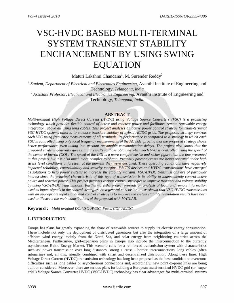
active power flow with the polarity of the DC voltage.In 2000, the first use of Insulated-Gate Bipolar Transistor
(IGBT) valves for HVDC was deployed in Australia with a 59 km, 180 MW, 80kV line. This type of voltage source
converter (VSC) based HVDC is known as VSC-HVDC, which has the ability to reverse the direction of power flow
by reversing the DC current but without reversing the DC voltage polarity VSC technology. Power flow in AC and
DC grid based on VSC Converter is shown in fig.1
Fig.1 Power flow in AC and DC grid based on VSC Converter
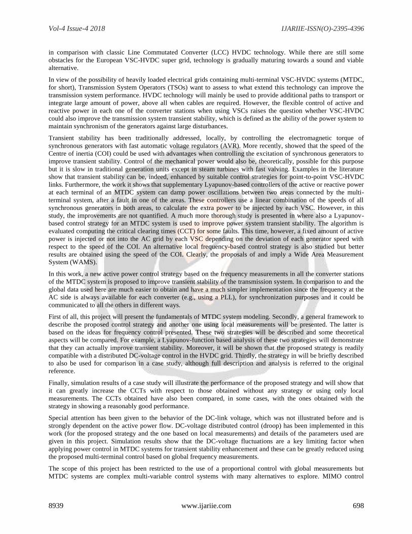
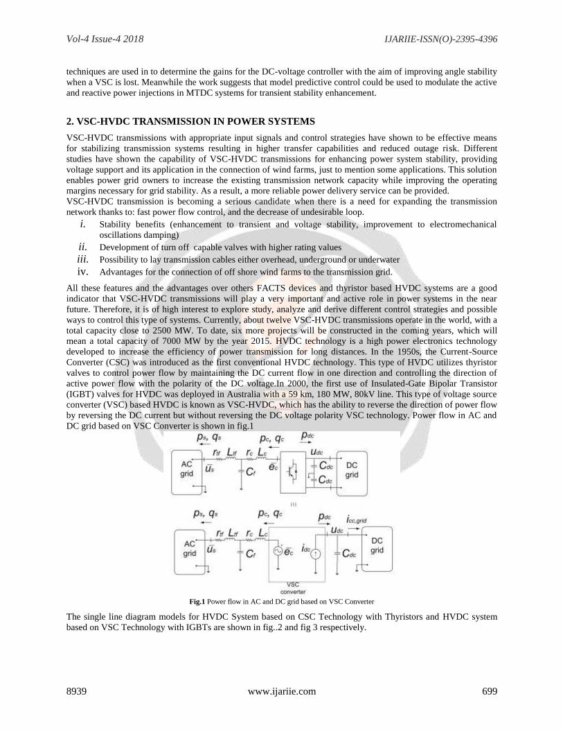
The single line diagram models for HVDC System based on CSC Technology with Thyristors and HVDC system
based on VSC Technology with IGBTs are shown in fig..2 and fig 3 respectively.
Vol-4 Issue-4 2018 IJARIIE-ISSN(O)-2395-4396
8939 www.ijariie.com 700
Fig.2 HVDC System Based on CSC Technology with Thyristors
Fig.3 HVDC system Based on VSC Technology with IGBTs
Many HVDC projects have been implemented and several others are currently under construction. Table 4.1 shows
the major HVDC projects that have been built between 1954 and 2011. In addition, Table 4.1 shows how the voltage
levels of HVDC projects have increased over the same time period. This reflects the growing demands of electrical
power and the development of HVDC systems over the years.
2.1 COMPARISON OF CONVENTIONAL HVDC AND VSC-HVDC
HVDC technology provides a good solution for transmitting electric power over long distances. Today, there are
two types of HVDC systems: conventional HVDC and VSC-HVDC. Conventional HVDC is characterized by
unidirectional DC current flow and the direction of active power flow is determined by DC voltage polarity. In
contrast to conventional HVDC systems, VSC-HVDC systems can reverse the active and reactive power flow by
reversing the DC current and without reversing the DC voltage polarity.
This makes the VSC-HVDC suitable for multi-terminal VSC-HVDC (M-VSC-HVDC) systems, as the DC voltage
polarity will not change when the power flow is reversed for a single VSC. In M-VSC-HVDC systems, the
individual transmission lines share a common DC voltage source and the power flow direction is determined by the
current flow on the individual lines.
Another difference between conventional HVDC and VSC-HVDC is that conventional HVDC converters consume
reactive power; therefore, they require a strong AC network for commutations. Since reactive power support is not
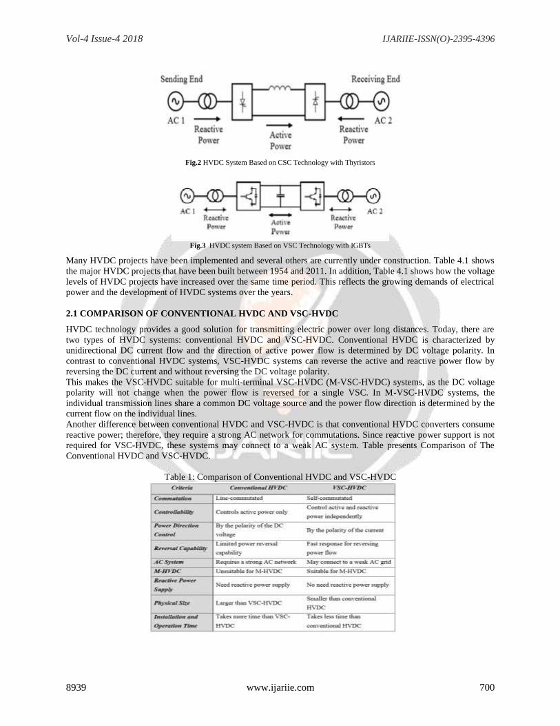
required for VSC-HVDC, these systems may connect to a weak AC system. Table presents Comparison of The
Conventional HVDC and VSC-HVDC.
Table 1: Comparison of Conventional HVDC and VSC-HVDC
Vol-4 Issue-4 2018 IJARIIE-ISSN(O)-2395-4396
8939 www.ijariie.com 701
HVDC transmission system based on Voltage Source Converters (VSCs) has taken on some excellent advantages.
The new VSC-HVDC system known as “HVDC Light” or “HVDC Plus” by leading vendors, has been applied in
several special occasions such as the connection of off-shore wind farms or oil drilling platforms into the mainland
electrical network and for underground transmission or distribution systems within congested cities. Thedifferences
in structure between the two types of converters (Conventional HVDC and VSC-HVDC) contribute tothe
differences in their performance. Generally, the new transmission technology has the following advantages
compared with conventional, thyristor based HVDC.
2.2 ADVANTAGES OF VSC-HVDC
-Possibility to control the reactive power (consumed or generated by the converter) independently of the active
power (to or from the converter).
i. No risk of commutation failures in the converter.
ii. Ability to connect to weak AC networks, or even dead networks.
iii. Faster response due to increased switching frequency (PWM).
iv. Minimal environmental impact.
However, VSC transmission does have some disadvantages, which include potentially high power losses and high
capital costs when compared with conventional HVDC, but the technology continues to evolve. This project
presents the elements of VSC-HVDC which uses twelve pulse three level converter topology and its control design.
Transmission system owners, and in general all different stakeholders, have had to carry out an optimization of their
assets in order to achieve a competitive position and survive in the new deregulated electricity market. This situation
has submitted the transmission network to high stress conditions that increase the probability of blackouts. On the
other hand, customers demand quality electricity supply from their respective supplier, including constant voltage, a
minimum of interruptions, if any, and constant frequency.
The objective of transmission system expansion is to increase the network capacity and effectively improve
edibility, reliability and security. Among many possible solutions to achieve this objective, FACTS devices and
HVDC systems play an important role. These type of devices/systems have shown to be capable in stabilizing
transmission systems, resulting in higher transfer capability.
An interesting question is how power electronics-based devices (FACTS and HVDC transmissions) can contribute
to keep system stability when an-other contingency occurs before fulfilling the second condition in Destination 1.
Most FACTS devices and thyristor-based HVDC systems only have one degree of freedom; i.e., they are able to
control either active or reactive power. However, Unified Power Flow Controllers (UPFCs) and VSC-HVDC trans-
mission systems are alternatives that have two degrees of freedom. They can control active and reactive power,
independent of each other. This feature gives UPFCs and VSC-HVDC transmissions a potential to enhance transient
stability, provide voltage support, increase damping, and control the power flow in a much larger extension
compared to other devices/systems.
Even though UPFCs and VSC-HVDC transmissions have similar characteristics, from the cost point of view, VSC-
HVDC transmissions, have the advantage of using conventional power transformers. UPFCs require the installation
of power transformers in series with transmission lines, which demand much higher levels of insulation, more
complex design and a more elaborate construction and installation.
VSC-HVDC transmissions with appropriate input signals and control strategies have shown to be effective means
for stabilizing transmission systems resulting in higher transfer capabilities and reduced outage risk. Different
studies have shown the capability of VSC-HVDC transmissions for enhancing power system stability, providing
voltage support and its application in the connection of wind farms, just to mention some applications. This solution
enables power grid owners to increase the existing transmission network capacity while improving the operating
margins necessary for grid stability. As a result, a more reliable power delivery service can be provided.
3. MODELLING OF VSC-HVDC TRANSMISSIONS
This chapter presents three different models for VSC-HVDC transmissions, namely Injection Model, Simple Model
and HVDC Light Open Model. The Injection Model and Simple Model are used for the derivation of CLF-based
control strategies. The HVDC Light Open Model is used for testing control strategies and analyzing the impact of
VSC-HVDC transmissions on power systems. The Injection Model and Simple Model have been presented in Paper
I and II. The Injection Model is intended for power and electromechanical dynamics analyses. For this reason it is
sufficient to consider the voltage and current phasors in the ac system. The Injection Model can be considered as an
element, which provides adequate interaction with other elements for enhancing the dynamic performance and
Vol-4 Issue-4 2018 IJARIIE-ISSN(O)-2395-4396
8939 www.ijariie.com 702
stability of the system as a whole. Harmonics and dc transient components are neglected, because they normally
have a second order effect on the active and reactive powers. Voltages and currents are represented by phasors in the
ac network, which vary with time during transients. The Injection Model is valid for symmetrical conditions, i.e., for
positive sequence voltages and currents. The model is used in the derivation and test of control strategies.
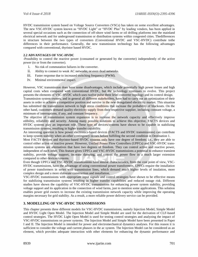
Fig.4 A simple block diagram of VSC-HVDC System
Generally the VSC-HVDC system is composed of converters, DC capacitors, transformer and filters. The role of the
transformer is to step up/down the AC voltage to satisfy the demand of self-commutated solid-state devices, such as
series and parallel of GTOs, IGBTs or IGCTs. High frequency components caused by the switches of valves are
isolated from power system by filters. The key parts of the VSC-HVDC are converters, which can realize the
conversion from AC to DC bi- directly. DC capacitors are used as the DC voltage source in VSC-HVDC , which
need being charged and recharged. The block diagram model of VSC-HVDC system is shown in fig. 10
The converter is composed of a three-phase, two level and six-pulse bridges the fundamental component of ac bus
voltage is the fundamental component of converter’s output. “” is the angle between the voltages Vs and Vr.
The power transmitted by VSC- HVDC is given as:
S=P+jQ or S= sqrt(3)VI*
For ac voltage control station, assume the dc voltage utilization ratio of the adopted PWM equals to 1 and the
modulation index of PWM is M. Then we have
From (5.1.1)-(5.1.3), the active power flowing over the line and Mof VSC is primarily determined by the angle. It
can change the amplitude of the reactive power and M can be used for regulating boththe active and reactive power,
If the converter’s output voltage is controlled as desired, the exchange power between AC and DC system is also
controlled. When δ>0, which means the US is leading UC, the active power will be transferred from AC to DC and
the converter is worked as rectifier. By contrast, the converter can also be worked as inverter. The converter will
generate reactive power, if Us > UC , and will absorb reactive power on the cos() contrary.
3.1 Control System of VSC-HVDC
The VSC-HVDC control system is based on PWM control technology, the amplitude and phase angle of VSC
output voltage can be regulated independently and rapidly by the modulation ratio M . So with the two
controllableand the shift angle, VSC can control the power Ps andvaries M and Qs in all four quadrants
Vol-4 Issue-4 2018 IJARIIE-ISSN(O)-2395-4396
8939 www.ijariie.com 703
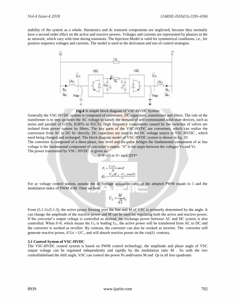
Fig.5 VSC power control schematic diagram
Under normal operation conditions, each VSC can control its reactive power independent of the other VSC.
However, the active power inject into the VSC- HVDC inner dc system must be balanced which means that active
power out from the dc network must equal the active power into the dc network minus the losses in the network.
Any difference will cause dc voltage increase or decrease. In order to achieve the active power balance
automatically, one of the VSCs should select its dc voltage as control object. The other VSC can control its active
power at any value within its capacity limits. The transfer-function block diagram of controllers for controlling VSC
active power, dc voltage, reactive power and ac bus voltage are all based on proportional integral (PI) regulators.
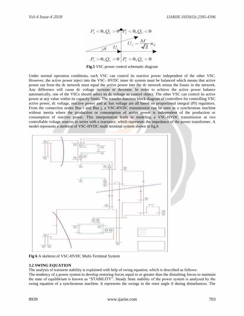
From the connection nodes Bus i and Bus j, a VSC-HVDC transmission can be seen as a synchronous machine
without inertia where the production or consumption of active power is independent of the production or
consumption of reactive power. This interpretation leads to modeling a VSC-HVDC transmission as two
controllable voltage sources in series with a reactance, which represents the impedance of the power transformer. A
model represents a skeleton of VSC-HVDC multi terminal system shown in fig.6
Fig 6 A skeleton of VSC-HVDC Multi-Terminal System
3.2 SWING EQUATION
The analysis of transient stability is explained with help of swing equation, which is described as follows:
The tendency of a power system to develop restoring forces equal to or greater than the disturbing forces to maintain
the state of equilibrium is known as “STABILITY”. Steady State stability of the power system is analyzed by the
swing equation of a synchronous machine. It represents the swings in the rotor angle if during disturbances. The
Vol-4 Issue-4 2018 IJARIIE-ISSN(O)-2395-4396
8939 www.ijariie.com 704
change in the rotor angle If results in change in real power, which ultimately affects the frequency. Hence swing
equation forms the basis for modeling of load frequency control (LFC) loop of the power system. Swing equation is
a rotational inertia equation describing the effect of unbalance between the electromagnetic torque and the
mechanical torque of the individual machines.
Under normal operating conditions, the relative position of the rotor axis and the resultant magnetic field axis is
fixed. The angle between the two axis is known as the power angle or torque angle. During any disturbance, rotor
will decelerate or accelerate with respect to the synchronously rotating air gap mmf and thereby developing relative
motion. The equation describing this relative motion is known as swing equation. After this oscillatory period, the
rotor locks back into synchronous speed, the generator will maintain its stability. If the disturbance does not involve
any net change in power, the rotor returns to its original position. If the disturbance is created by a change in
generation, load, or in network conditions, the rotor comes to a new operating power angle relative to the
synchronously revolving field. In this section the equation describing the relative motion called swing equation is
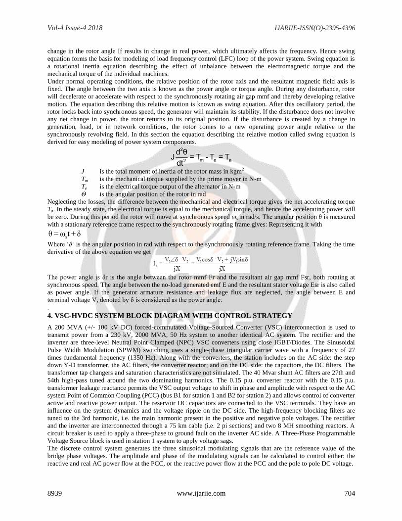
derived for easy modeling of power system components. 2
m e a2
d θJ = T - T = Tdt
J is the total moment of inertia of the rotor mass in kgm2
Tm is the mechanical torque supplied by the prime mover in N-m
Te is the electrical torque output of the alternator in N-m
Θ is the angular position of the rotor in rad
Neglecting the losses, the difference between the mechanical and electrical torque gives the net accelerating torque
Ta. In the steady state, the electrical torque is equal to the mechanical torque, and hence the accelerating power will
be zero. During this period the rotor will move at synchronous speed ωs in rad/s. The angular position θ is measured
with a stationary reference frame respect to the synchronously rotating frame gives: Representing it with
sθ = ω t + δ
Where ‘δ’ is the angular position in rad with respect to the synchronously rotating reference frame. Taking the time
derivative of the above equation we get
The power angle įs δr is the angle between the rotor mmf Fr and the resultant air gap mmf Fsr, both rotating at
synchronous speed. The angle between the no-load generated emf E and the resultant stator voltage Esr is also called
as power angle. If the generator armature resistance and leakage flux are neglected, the angle between E and
terminal voltage V, denoted by δ is considered as the power angle.
.
4. VSC-HVDC SYSTEM BLOCK DIAGRAM WITH CONTROL STRATEGY
A 200 MVA (+/- 100 kV DC) forced-commutated Voltage-Sourced Converter (VSC) interconnection is used to
transmit power from a 230 kV, 2000 MVA, 50 Hz system to another identical AC system. The rectifier and the
inverter are three-level Neutral Point Clamped (NPC) VSC converters using close IGBT/Diodes. The Sinusoidal
Pulse Width Modulation (SPWM) switching uses a single-phase triangular carrier wave with a frequency of 27
times fundamental frequency (1350 Hz). Along with the converters, the station includes on the AC side: the step
down Y-D transformer, the AC filters, the converter reactor; and on the DC side: the capacitors, the DC filters. The
transformer tap changers and saturation characteristics are not simulated. The 40 Mvar shunt AC filters are 27th and
54th high-pass tuned around the two dominating harmonics. The 0.15 p.u. converter reactor with the 0.15 p.u.
transformer leakage reactance permits the VSC output voltage to shift in phase and amplitude with respect to the AC
system Point of Common Coupling (PCC) (bus B1 for station 1 and B2 for station 2) and allows control of converter
active and reactive power output. The reservoir DC capacitors are connected to the VSC terminals. They have an
influence on the system dynamics and the voltage ripple on the DC side. The high-frequency blocking filters are
tuned to the 3rd harmonic, i.e. the main harmonic present in the positive and negative pole voltages. The rectifier
and the inverter are interconnected through a 75 km cable (i.e. 2 pi sections) and two 8 MH smoothing reactors. A
circuit breaker is used to apply a three-phase to ground fault on the inverter AC side. A Three-Phase Programmable
Voltage Source block is used in station 1 system to apply voltage sags.
The discrete control system generates the three sinusoidal modulating signals that are the reference value of the
bridge phase voltages. The amplitude and phase of the modulating signals can be calculated to control either: the
reactive and real AC power flow at the PCC, or the reactive power flow at the PCC and the pole to pole DC voltage.
Vol-4 Issue-4 2018 IJARIIE-ISSN(O)-2395-4396
8939 www.ijariie.com 705
The system is programmed to start and reach a steady state. Steps are then applied sequentially on: the reference
active and reactive power of the rectifier; the reference DC voltage of the inverter. The dynamic response of the
regulators is observed. Start the simulation. Open the BUS B1 STATION_1 and DC_SIDE_STATION_2 scopes (in
the respective Data Acquisition subsystems). Examine in station 1: the active power on trace 2 (1 p.u. = 200 MW)
and the reactive power (reference and measured values) on trace 3 (1 p.u. =200 Mvar); in station 2: the DC voltage
(reference and measured values) on trace 2 (1 p.u. = 200 kV). At t = 1.5 s, a -0.1 p.u. step is first applied to the
reference active power (decrease from 1 p.u. to 0.9 p.u). The power stabilizes in approximately 0.3 seconds. Steps
are also applied to the reference reactive power of the rectifier (from 0 to -0.1 p.u.) at t = 2.0 s and on the reference
DC voltage of the inverter (decrease from 1 p.u. to 0.95 p.u.) at t = 2.5 s. Note the regulators dynamics and how they
are more or less mutually affected. The control design attempts to decouple the active and reactive power responses.
4.1 AC SIDE PERTURBATIONS
Deactivate the steps applied on the three references by changing the multiplication factors to 100 in the Step times.
In the “Three-Phase Programmable Voltage Source” inside AC system 1 subsystem, change the Time variation
setting to “Amplitude”. Check that the source is now programmed for a step of -0.1 p.u on voltage magnitude at t =
1.5 s, for a duration of 7 cycles. In the “Three-Phase Fault” block change to 1 the multiplication factor in the
Transition times. A 6 cycles three-phase fault will be applied at t = 2.1 s in station 2 PCC (Bus B2). Restart the
simulation. After the AC voltage sag in station 1, the active and reactive power deviation from the pre-disturbance is
less than 0.09 p.u. and 0.2 p.u. respectively. The recovery time is less than 0.3 s and steady state is reached again. A
second perturbation follows. During the severe three-phase fault at station 2, the transmitted DC power is almost
halted and the DC voltage tends to increase (1.2 p.u.) since the DC side capacitance is being excessively charged. A
special function (DC Voltage Control Override) in the Active Power Control (in station 1) attempts to limit the DC
voltage within a fixed range (see the controller mask). The system recovers well after the fault within 0.5 s. You can
observe overshoot in the active power (1.33 p.u. in station 1) and damped oscillations (around 10 Hz) in the reactive
power.
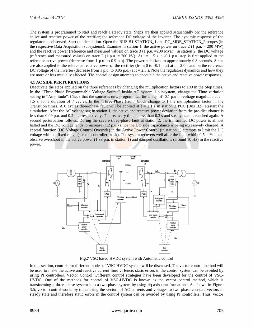
Fig.7 VSC based HVDC system with Automatic control
In this section, controls for different modes of VSC-HVDC system will be discussed. The vector control method will
be used to make the active and reactive current linear. Hence, static errors in the control system can be avoided by
using PI controllers. Vector Control: Different control strategies have been developed for the control of VSC-
HVDC. One of the methods for control of VSC-HVDC is known as the vector control method, which is
transforming a three-phase system into a two-phase system by using dq-axis transformations. As shown in Figure
3.5, vector control works by transferring the vectors of AC currents and voltages to two-phase constant vectors in
steady state and therefore static errors in the control system can be avoided by using PI controllers. Thus, vector
Vol-4 Issue-4 2018 IJARIIE-ISSN(O)-2395-4396
8939 www.ijariie.com 706
control systems can be used to obtain independent control of the active and reactive powers. The VSC is one of
many devices that have been developed to make the high-voltage side of the network electronically controllable.
This group of devices is called flexible ac transmission system (FACTS). Many operational problems in power
systems have been solved using HVDC and FACTS devices. Although most of the existing HVDC installations are
two terminal installations, it is possible to connect three or more terminals using voltage source converters (VSCs).
Therefore, HVDC and FACTS devices may contribute more features to transmission of electrical power than in the
case of using conventional AC transmission.
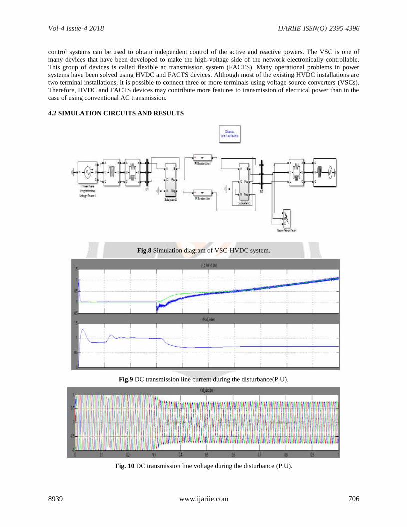
4.2 SIMULATION CIRCUITS AND RESULTS
Fig.8 Simulation diagram of VSC-HVDC system.
Fig.9 DC transmission line current during the disturbance(P.U).
Fig. 10 DC transmission line voltage during the disturbance (P.U).
Vol-4 Issue-4 2018 IJARIIE-ISSN(O)-2395-4396
8939 www.ijariie.com 707
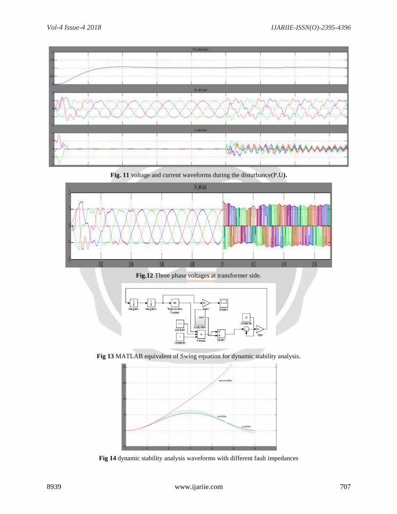
Fig. 11 voltage and current waveforms during the disturbance(P.U).
Fig.12 Three phase voltages at transformer side.
Fig 13 MATLAB equivalent of Swing equation for dynamic stability analysis.
Fig 14 dynamic stability analysis waveforms with different fault impedances
Vol-4 Issue-4 2018 IJARIIE-ISSN(O)-2395-4396
8939 www.ijariie.com 708
4. CONCLUSIONS
It was shown that VSC-HVDC transmissions with the appropriate control strategy are able to improve stability
margins in power systems. It has been shown that to increase power transfer capacity in the transmission grid by
installing either a new ac transmission line or a VSC-HVDC transmission, the latter significantly enhances transient
and voltage stability, improves the damping of electromechanical oscillations and contributes towards the efficient
utilization of the transmission system. In VSC-HVDC system dynamic stability is more as compared with normal
HVDC system. Because VSC-HVDC power flow in the line can be controlled effectively by using voltage source
converters. By using swing equation the dynamic stability of the power system is simulated and shown that by
changing the fault impedance on the transmission system it can bring back to the stability from the unstable region.
6. REFERENCES
[1] W. Long and S. Nilsson, HVDC transmission: Yesterday and today, IEEE Power Energy Magazine, vol. 5, no.
2, pp. 22 31, 2007.
[2] ABB. The early HVDC development. [Online]. Available:
http://www.abb.com/industries/db0003db004333/4c642ca2c9d6b860 c125748100247a5e.aspx
[3] S. Cole and R. Belmans, Transmission of bulk power, IEEE Industrial Electronics Magazine, vol. 3, no. 3, pp.
19 24, September 2009.
[4] U. Axelsson, A. Holm, C. Liljegren, K. Eriksson, and L. Weimers, Got-land HVDC Light transmission -world's
rst commercial small scale dc transmission, in CIRED, May 1999.Energy Information Administration,
International energy outlook 2009, Cigré, Tech. Rep., May 2009.
[5] T. Slocum, The failure of electricity deregulation: History, status and needed reforms, Public Citizen, Tech.
Rep., October 2008.
[6] P. Marannino, P. Bresesti, A. Garavaglia, F. Zanellini, and R. Vailati, Assessing the transmission transfer
capability sensitivity to power sys-tem, in Power System Computation Conference , June 2002.
[7] Robust damping of interarea oscillations in power systems using facts
controllers.Available:http://www3.imperial.ac.uk/controlandpower/research/portfoliopart nership/projects
[8] M. V. Venkatasubramanian, Analyzing blackout events: Experience from the major Western blackouts in 1996,
Power Systems Engineering Research Center, Tech. Rep., August 2003.
[9] D. Kirschen and G. Strbac, Why investments do not prevent blackouts, The Electricity Journal, vol. 17, pp. 29
36, 2004.
[10] H. K. Clark, New challenge: Voltage stability, IEEE Power Engineer-ing review, vol. 18, no. 7, pp. 445 452,
1990.
[11] U. S. - Canada Power System Outage Task Force, Final report on the August 14th, 2003 blackout in the United
States and Canada: causes and recommendations, U. S. Energy Information Adminsitration, Tech. Rep., 2004.
[12] SvenskaKraftnät, Elavbrottet 23 september 2003 händelseroch at-gärder, SvK, Tech. Rep., Nov. 2003.
[13] C. D. Vournas, G. A. Manos, J. Kabouris, and T. V. Cutsem, Analysis of voltage instability incident in the
Greek power systems, in Power Engineering Society Winter Meeting , vol. 2, January 2000, pp. 1483 1488.
[14] UCTE, Final report system disturbance on 4 November 2006, UCTE, Tech. Rep., 2007.
[15] L. Kirschner, D. Retzmann, and G. Thumm, Benets of FACTS for power system enhancement, in IEEE/PES
Transmission and Distribu-tion Conference & Exhibition: Asia and Pacic , 2005.
[16] R. Grünbaum, B. Halvarsson, and A. Wilk-Wilczynski, FACTS and HVDC Light for power system
interconnections, in Power Delivery, 1999.
[17] SvenskaKraftnät, Annual report, SvK, Tech. Rep., 2009.
[18] M. Ghandhari, Dynamic analysis of power system Part II, Electric Power Systems, KTH, Tech. Rep., 2007.
[19] J. Machowski, J. W. Bialek, and J. R. Bumby, Power System Dynamics and Stability. John Wiley & Sons,
1997.
[20] IEEE/CIGRE Joint Task Force on Stability Terms and De nitions, De nition and classication of power system
stability, IEEE Trans-actions on Power Systems , vol. 19, no. 2, pp. 1387 1401, May 2004.
[21] K. R. Padiyar and S. S. Rao, Dynamic analysis of small signal volt-age stability decoupled from angle stability,
Electric Power & Energy Systems, vol. 18, no. 7, pp. 445 452,
Recommended