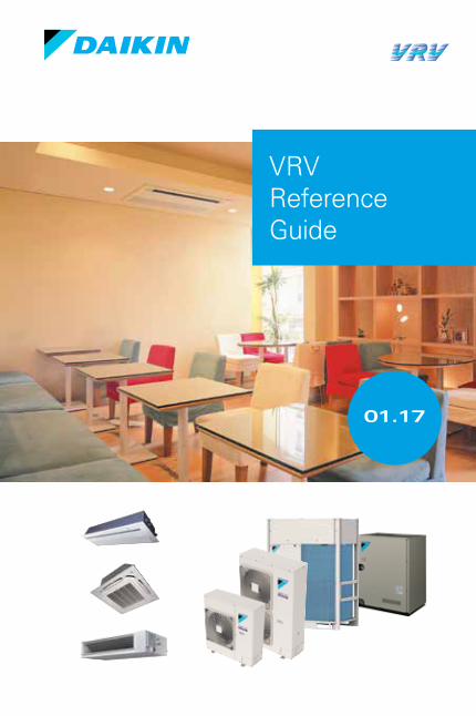
01.17
VRV Reference Guide

About Daikin:
Daikin Industries, Ltd. (DIL) is a global Fortune 1000 company which celebrated its 90th anniversary in May 2014. The company is recognized as one of the largest HVAC (Heating, Ventilation, Air Conditioning) manufacturers in the world. DIL is primarily engaged in developing indoor comfort products and refrigeration systems for residential, commercial and industrial applications. Its consistent success is derived, in part, from a focus on innovative, energy-efficient and premium quality indoor climate and comfort management solutions.
A WORLD LEADING MANUFACTURER OF HVAC PRODUCTS
OPERATING
F O U N D E DI N 1 9 2 4
R E S E A R C H DEVELOPMENT O V E R $ 3 0 0 M I L L I O N
O V E R 6 0 , 0 0 0 0 D A I K I N V R V S Y S T E M S
T H R O U G H O U T N O R T H A M E R I C A
TABLE OF CONTENTS
SYSTEM OVERVIEW The Features of VRV ........................................................................... 6
Key Points For Selection .................................................................... 8
Capacity Range & Operating Limits ............................................. 12
Nomenclature .................................................................................... 15
SYSTEM SELECTIONIndoor Unit Range ............................................................................. 18
Indoor Unit Consideration ..............................................................20
Zoning VRV Systems with DZK ...................................................... 24
Heat Pump or Heat Recovery? .......................................................26
Air Cooled or Water Cooled? .........................................................29
Solutions For Ventilation .................................................................32
DESIGN OPTIMIZATIONSystem Zoning ...................................................................................36
Branch Selector Boxes ...................................................................40
Single or Multi BSV Boxes? ............................................................ 41
Piping Sizes and Optimization ........................................................43
Outdoor Unit Installation Space ....................................................45
Heat Pump Changeover ................................................................... 47
CONTROLS & STANDARDSControls Portfolio .............................................................................52
Local Control Options ......................................................................56
Featured Controls ..............................................................................57
Codes & Standards ...........................................................................59
Tips & Considerations .....................................................................60
Future Documents & Data .............................................................. 61


SystemOverview
6
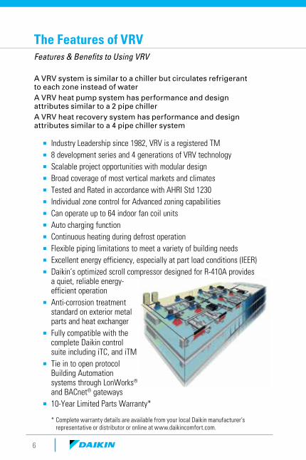
The Features of VRV Features & Benefits to Using VRV
A VRV system is similar to a chiller but circulates refrigerant to each zone instead of waterA VRV heat pump system has performance and design attributes similar to a 2 pipe chillerA VRV heat recovery system has performance and design attributes similar to a 4 pipe chiller system
¡ Industry Leadership since 1982, VRV is a registered TM ¡ 8 development series and 4 generations of VRV technology ¡ Scalable project opportunities with modular design ¡ Broad coverage of most vertical markets and climates ¡ Tested and Rated in accordance with AHRI Std 1230 ¡ Individual zone control for Advanced zoning capabilities ¡ Can operate up to 64 indoor fan coil units ¡ Auto charging function ¡ Continuous heating during defrost operation ¡ Flexible piping limitations to meet a variety of building needs ¡ Excellent energy efficiency, especially at part load conditions (IEER) ¡ Daikin’s optimized scroll compressor designed for R-410A provides
a quiet, reliable energy-efficient operation
¡ Anti-corrosion treatment standard on exterior metal parts and heat exchanger
¡ Fully compatible with the complete Daikin control suite including iTC, and iTM
¡ Tie in to open protocol Building Automation systems through LonWorks® and BACnet® gateways
¡ 10-Year Limited Parts Warranty*
* Complete warranty details are available from your local Daikin manufacturer’s representative or distributor or online at www.daikincomfort.com.
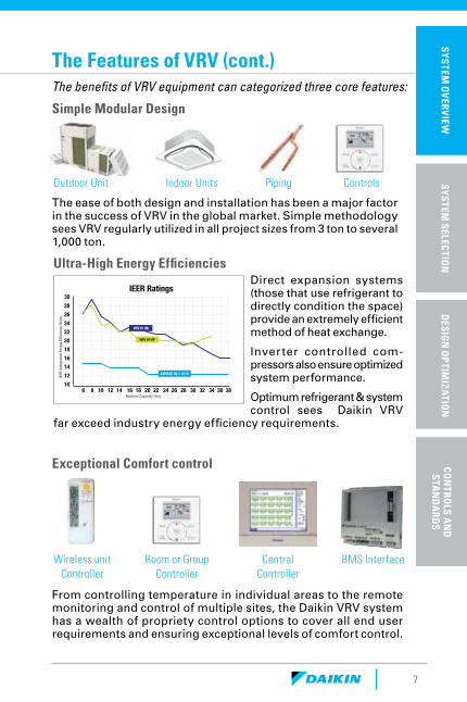
IEER Ratings
6 8 10 12 14 16 18 20 22 24 26 28 30 32 34 36 38Nominal Capacity (Ton)
28262422201816141210
30
IEER
(Int
egra
ted
Ener
gy E
fficie
ncy R
atio
)
VRV IV HP
VRV IV HR
ASHRAE 90.1 2010
7
The Features of VRV (cont.)The benefits of VRV equipment can categorized three core features:
From controlling temperature in individual areas to the remote monitoring and control of multiple sites, the Daikin VRV system has a wealth of propriety control options to cover all end user requirements and ensuring exceptional levels of comfort control.
Outdoor Unit
Wireless unit Controller
Indoor Units
Room or Group Controller
Piping
Central Controller
Controls
BMS Interface
Ultra-High Energy Efficiencies
Exceptional Comfort control
Direct expansion systems (those that use refrigerant to directly condition the space) provide an extremely efficient method of heat exchange.
Inverter controlled com-pressors also ensure optimized system performance.
Optimum refrigerant & system control sees Daikin VRV
far exceed industry energy efficiency requirements.
The ease of both design and installation has been a major factor in the success of VRV in the global market. Simple methodology sees VRV regularly utilized in all project sizes from 3 ton to several 1,000 ton.
Simple Modular Design
SP
ECIF
ICA
TIO
NS
& A
CC
ESS
OR
IES
SYSTEM
OV
ERVIEW
SYSTEM
SELECTIO
ND
ESIGN
OP
TIMIZA
TION
CON
TROLS A
ND
S
TAN
DA
RDS
8
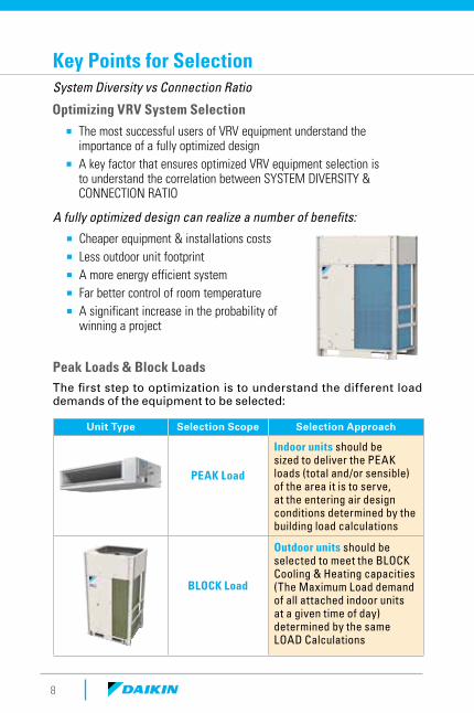
A fully optimized design can realize a number of benefits:
¡ Cheaper equipment & installations costs ¡ Less outdoor unit footprint ¡ A more energy efficient system ¡ Far better control of room temperature ¡ A significant increase in the probability of
winning a project
Key Points for SelectionSystem Diversity vs Connection Ratio
Unit Type Selection Scope Selection Approach
PEAK Load
Indoor units should be sized to deliver the PEAK loads (total and/or sensible) of the area it is to serve, at the entering air design conditions determined by the building load calculations
BLOCK Load
Outdoor units should be selected to meet the BLOCK Cooling & Heating capacities (The Maximum Load demand of all attached indoor units at a given time of day) determined by the same LOAD Calculations
Optimizing VRV System Selection
¡ The most successful users of VRV equipment understand the importance of a fully optimized design
¡ A key factor that ensures optimized VRV equipment selection is to understand the correlation between SYSTEM DIVERSITY & CONNECTION RATIO
Peak Loads & Block LoadsThe first step to optimization is to understand the different load demands of the equipment to be selected:
9
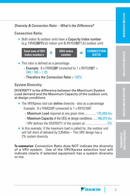
Diversity & Connection Ratio - What’s the Difference?
Connection Ratio:
¡ Both indoor & outdoor units have a Capacity Index number (e.g. FXMQ30PBVJU indoor unit & RXYQ192TTJU outdoor unit)
Total sum of IDU index numbers ÷ ODU index
number = CONNECTION RATIO
¡ This ratio is defined as a percentage: – Example: 8 x FXMQ30P connected to 1 x RXYQ192T = 240 / 192 = 1.25
– Therefore the Connection Ratio = 125%
System Diversity:DIVERSITY is the difference between the Maximum System Load demand and the Maximum Capacity of the outdoor unit, at design conditions
¡ The VRVXpress tool can define diversity - also as a percentageExample: 8 x FXMQ30P connected to 1 x RXYQ168T
– Maximum Load required at any given time: ..............170,269 btu – Maximum Capacity of the ODU at design conditions: .....166,315 btu – VRV defines the DIVERSITY of the system at: ..........................-2%
¡ In this example, if the maximum load is called for, the outdoor unit will fall short of demand by 3,954btu – This VRV design has a 2% system diversity
To summarize: Connection Ratio does NOT indicate the diversity of a VRV system. Use of the VRVXpress selection tool will indicate clearly if selected equipment has a system diversity or not.
SP
ECIF
ICA
TIO
NS
& A
CC
ESS
OR
IES
SYSTEM
OV
ERVIEW
SYSTEM
SELECTIO
ND
ESIGN
OP
TIMIZA
TION
CON
TROLS A
ND
S
TAN
DA
RDS
10
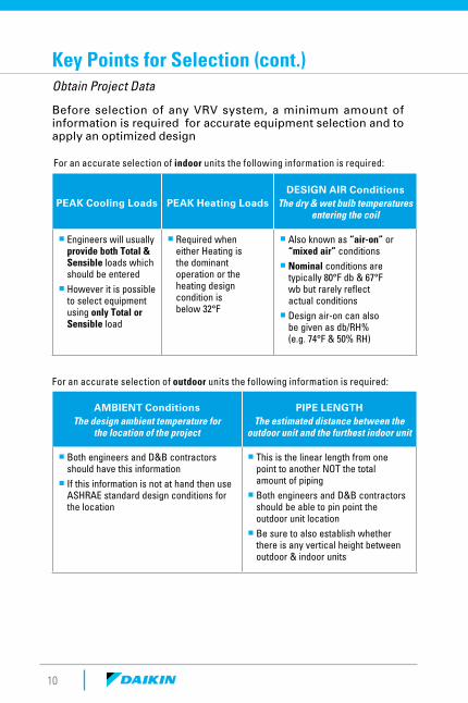
Before selection of any VRV system, a minimum amount of information is required for accurate equipment selection and to apply an optimized design
For an accurate selection of indoor units the following information is required:
For an accurate selection of outdoor units the following information is required:
PEAK Cooling Loads PEAK Heating LoadsDESIGN AIR Conditions
The dry & wet bulb temperatures entering the coil
¡ Engineers will usually provide both Total & Sensible loads which should be entered ¡ However it is possible to select equipment using only Total or Sensible load
¡ Required when either Heating is the dominant operation or the heating design condition is below 32°F
¡ Also known as “air-on” or “mixed air” conditions ¡ Nominal conditions are typically 80°F db & 67°F wb but rarely reflect actual conditions ¡ Design air-on can also be given as db/RH% (e.g. 74°F & 50% RH)
AMBIENT ConditionsThe design ambient temperature for
the location of the project
PIPE LENGTHThe estimated distance between the
outdoor unit and the furthest indoor unit
¡ Both engineers and D&B contractors should have this information ¡ If this information is not at hand then use ASHRAE standard design conditions for the location
¡ This is the linear length from one point to another NOT the total amount of piping ¡ Both engineers and D&B contractors should be able to pin point the outdoor unit location ¡ Be sure to also establish whether there is any vertical height between outdoor & indoor units
Key Points for Selection (cont.)Obtain Project Data
11
SP
ECIF
ICA
TIO
NS
& A
CC
ESS
OR
IES
SYSTEM
OV
ERVIEW
SYSTEM
SELECTIO
ND
ESIGN
OP
TIMIZA
TION
CON
TROLS A
ND
S
TAN
DA
RDS
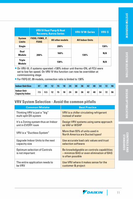
Common Mistake Best Practice
Thinking VRV is just a “big” multi split DX system
VRV is a chiller circulating refrigerant instead of water
It’s a Zoning system thus an Indoor unit in EVERY room
Design VRV systems using same approach as VAV or WSHP
VRV is a “Ductless System” More than 55% of units used in North America are Ducted types!
Upgrade Indoor Units to the next capacity size
Use accurate load calc values and trust selection software
Optimum selection of Controls is not important
Be knowledgeable on controls capabilities – minimize BAS or even elimination of BAS is often possible
The entire application needs to be VRV
Use VRV where it makes sense for the customer & project
VRV System Selection - Avoid the common pitfalls
VRV IV Heat Pump & Heat Recovery, Aurora Series VRV-IV W-Series VRV-S
System Limits
FXDQ, FXMQ_P, FXAQ
All other models All Indoor Units
Single
200%
200%
130%
130%
Dual Module
160% N/A
Triple Module
130% N/A
¡ On VRV-III, if systems operated >130% indoor unit thermo-ON, all FCU were set to low fan speed. On VRV IV this function can now be overridden at commissioning stage ¡ For FXFQ 07, 09 models, connection ratio is limited to 130%
Indoor Unit Size 07 09 12 15 18 24 30 36 42 48 54 72 96
Indoor Unit Capacity Index
7.5 9.5 12 15 18 24 30 36 42 48 54 72 96
12
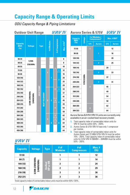
Capacity Range & Operating LimitsODU Capacity Range & Piping Limitations
Outdoor Unit Range Aurora Series & 575V
Capacity MBH (Tn)
Voltage Type
# of
Mod
ules
# of
Com
pres
sors
Max
. # ID
U1
36 (3)1/208-
230/60Hz
HEA
T PU
MP
1
1
6
48 (4) 8
60 (5) 10
72 (6)
3/20
8-23
0V/6
0Hz
3/46
0V/6
0Hz
HEA
T RE
COVE
RY
1
1 12
96 (8)
2
16
120 (10) 20
144 (12)
2
25
168 (14) 29
192 (16)
2 2
3 33
216 (18)
4
37
240 (20) 41
264 (22) 3 45
288 (24)
4
49
312 (26) 54
336 (28) 58
360 (30)
3
3
3
6
62
384 (32) 4 64
408 (34) 5 64
432 (36) 64
456 (38) 64
Capacity Voltage Type # of Modules
# of Compressors
Max. # IDU
72 (6)
3/20
8-23
0V/6
0Hz
3/46
0V/6
0Hz
Uni
fied
HP
or H
R
1 1 12
84 (7) 1 1 14
144 (12) 2 2 24
168 (14) 2 2 29
216 (18) 3 3 36
252 (21) 3 3 36
Capacity MBH (Tn) Vo
ltage
# of Modules / Compressors2 Max. # IDU3
575 Aurora 575 Aurora
72 (6)
575V
/3/6
0Hz
1
1
12
96 (8) 16
120 (10) 20
144 (12) 2 25
168 (14) 29
192 (16)
2
2 33
216 (18) 37
240 (20) 2 41
264 (22) 45
288 (24) 49
312 (26) 54
336 (28) 58
360 (30)3
62
384 (32) 64
1. Total capacity index of connectable indoor units for VRV IV must be within 50% - 200%.
2. Aurora Series & 575V VRV IV have only 1 compressor per module.
3. Total capacity index of connectable indoor units for Aurora Series and 72 MBH 575V VRV IV must be within 70% - 200%. Total capacity index of connectable indoor units for 575V VRV IV 96MBH – 384MBH must be within 50% - 200%.
Total capacity index of connectable indoor units must be within 50%-130%.
Aurora Series & 575V VRV IV units are currently only available in an air-cooled heat recovery model.
A
C
H
E
G
B
F
Range in Cooling
Range inHeating
113 F
95 F
27 F
*14 F
Entering Water
IndoorTemperature
* Conditions apply when entering water temperature is below 50ºF. Refer to your local Daikin Representative for further information.
50 F 59 F 80 F 82 F
122 F
77 F
23 F
10 F
VIA extended capacity tables
-4 F
-13 F
-22 F
Ambient Heat Pump Heat Recovery
COO
LIN
G
COO
LIN
G
HEA
TIN
G
HEA
TIN
G
AU
RORA
Ser
ies
Stan
dard
Ope
ratin
g Ra
nge
SIM
ULT
AN
EOU
S
VIA technical cooling functionCooling operation for VRV IV Heat Pump single module systems(RXYQ72/96/120/144/168T) can be extended down to 10˚F, from the standard limitation of 23˚F under defined conditions.Contact your local Daikin manufacturer’s representative or distributor for details.
D
13
SP
ECIF
ICA
TIO
NS
& A
CC
ESS
OR
IES
SYSTEM
OV
ERVIEW
SYSTEM
SELECTIO
ND
ESIGN
OP
TIMIZA
TION
CON
TROLS A
ND
S
TAN
DA
RDS
Tem
pera
ture
Lim
its
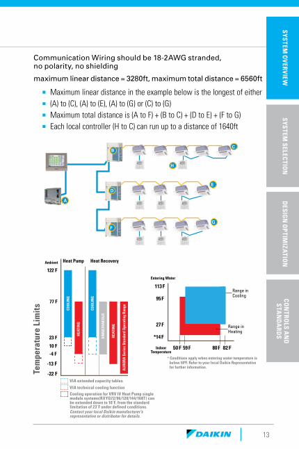
Communication Wiring should be 18-2AWG stranded, no polarity, no shielding
maximum linear distance = 3280ft, maximum total distance = 6560ft
¡ Maximum linear distance in the example below is the longest of either ¡ (A) to (C), (A) to (E), (A) to (G) or (C) to (G) ¡ Maximum total distance is (A to F) + (B to C) + (D to E) + (F to G) ¡ Each local controller (H to C) can run up to a distance of 1640ft
B
A
C
D
E
14
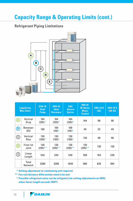
Refrigerant Piping Limitations
Liquid Line Max (feet)
VRV-IV Heat Pump
VRV-IV Heat
Recovery
VRV Aurora Series
VRV-IV W-Series
Water Cooled
VRV-IV S(36)
VRV-IV S(48-60)
A Vertical Drop
164 (295)*
164 (295)*
164 (295)* 164 98 98
B Between IDU 100 100
(49)†100
(49)† 49 33 49
C Vertical Rise
130 (295)*
130 (195)*
130 (195)* 130 98 98
D From 1st Joint
130 (295)**
130 (295)**
130 (295)**
130 (295)** 130 130
E Linear Length 540 540 540 390 164 230
Total Network 3280 3280 1640 980 820 984
* Setting adjustment on condensing unit required.** Fan coil distance differentials need to be met † Possible refrigerant noise can be mitigated (via setting adjustments on ODU) when linear length exceeds 390FT.
Capacity Range & Operating Limits (cont.)
15
SP
ECIF
ICA
TIO
NS
& A
CC
ESS
OR
IES
SYSTEM
OV
ERVIEW
SYSTEM
SELECTIO
ND
ESIGN
OP
TIMIZA
TION
CON
TROLS A
ND
S
TAN
DA
RDS
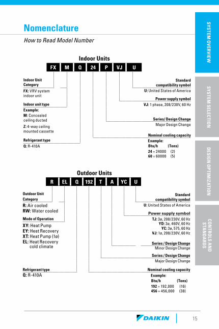
NomenclatureHow to Read Model Number
FX M Q 24 P VJ U
Indoor Unit Category
Standard compatibility symbol
FX: VRV system indoor unit
U: United States of America
Power supply symbolIndoor unit type VJ: 1 phase, 208/230V, 60 HzExample: M: Concealed ceiling ducted Series/ Design Change
Z: 4-way ceiling mounted cassette
Major Design Change
Nominal cooling capacityRefrigerant type Example:Q: R-410A Btu/h (Tons)
24 = 24000 (2) 60 = 60000 (5)
R EL Q 192 T A YC U
Outdoor Unit Category
Standard compatibility symbol
R: Air cooled RW: Water cooled
U: United States of America
Power supply symbolMode of Operation TJ: 3ø, 208/230V, 60 Hz
XY: Heat Pump EY: Heat RecoveryXT: Heat Pump (1ø)EL: Heat Recovery cold climate
YD: 3ø, 460V, 60 Hz YC: 3ø, 575, 60 Hz
VJ: 1ø, 208/230V, 60 Hz
T Series / Design ChangeMinor Design Change
Series / Design ChangeMajor Design Change
Refrigerant type Nominal cooling capacityQ: R-410A Example:
Btu/h (Tons) 192 = 192,000 (16)
456 = 456,000 (38)
Indoor Units
Outdoor Units

SystemSelection
18
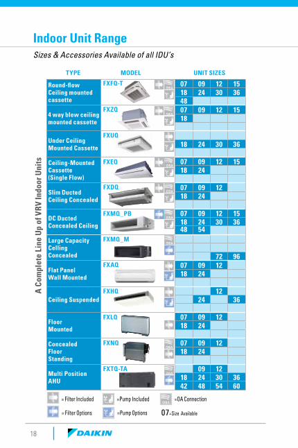
Indoor Unit RangeSizes & Accessories Available of all IDU’s
Round-flow Ceiling mounted cassette
07 09 12 1518 24 30 3648
4 way blow ceiling mounted cassette
07 09 12 1518
Under Ceiling Mounted Cassette 18 24 30 36
Ceiling-Mounted Cassette (Single Flow)
07 09 12 1518 24
Slim Ducted Ceiling Concealed
07 09 1218 24
DC Ducted Concealed Ceiling
07 09 12 1518 24 30 3648 54
Large Capacity Celling Concealed 72 96
Flat Panel Wall Mounted
07 09 1218 24
Ceiling Suspended12
24 36
Floor Mounted
07 09 1218 24
Concealed Floor Standing
07 09 1218 24
Multi Position AHU
09 1218 24 30 3642 48 54 60
FXZQ
FXFQ-T
FXMQ_PB
FXMQ_M
FXLQ
FXNQ
FXAQ
FXHQA C
ompl
ete
Line
Up
of V
RV In
door
Uni
ts
FXTQ-TA
FXDQ
FXEQ
TYPE MODEL UNIT SIZES
= Filter Included
=Pump Included
=OA Connection
= Filter Options
=Pump Options 07=Size Available
FXUQ
19
SP
ECIF
ICA
TIO
NS
& A
CC
ESS
OR
IES
SYSTEM
OV
ERVIEW
SYSTEM
SELECTIO
ND
ESIGN
OP
TIMIZA
TION
CON
TROLS A
ND
S
TAN
DA
RDS
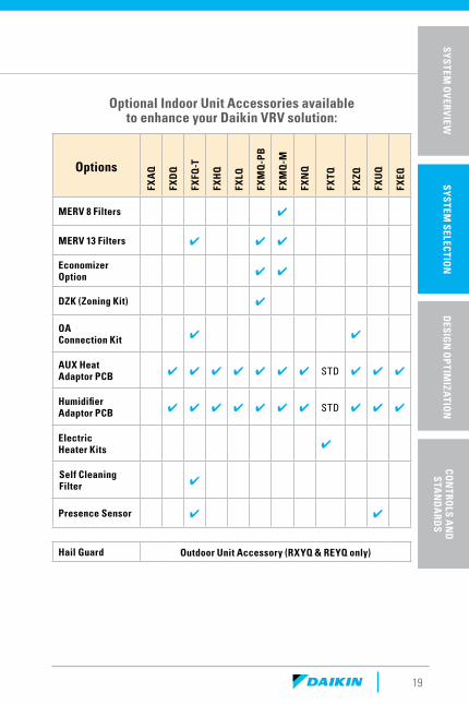
Optional Indoor Unit Accessories available to enhance your Daikin VRV solution:
OptionsFX
AQ
FXD
Q
FXFQ
-T
FXH
Q
FXLQ
FXM
Q-P
B
FXM
Q-M
FXN
Q
FXTQ
FXZQ
FXU
Q
FXEQ
MERV 8 Filters ✔
MERV 13 Filters ✔ ✔ ✔
Economizer Option ✔ ✔
DZK (Zoning Kit) ✔
OA Connection Kit ✔ ✔
AUX Heat Adaptor PCB ✔ ✔ ✔ ✔ ✔ ✔ ✔ STD ✔ ✔ ✔
Humidifier Adaptor PCB ✔ ✔ ✔ ✔ ✔ ✔ ✔ STD ✔ ✔ ✔
Electric Heater Kits ✔
Self Cleaning Filter ✔
Presence Sensor ✔ ✔
Hail Guard Outdoor Unit Accessory (RXYQ & REYQ only)
20
Indoor Unit Considerations
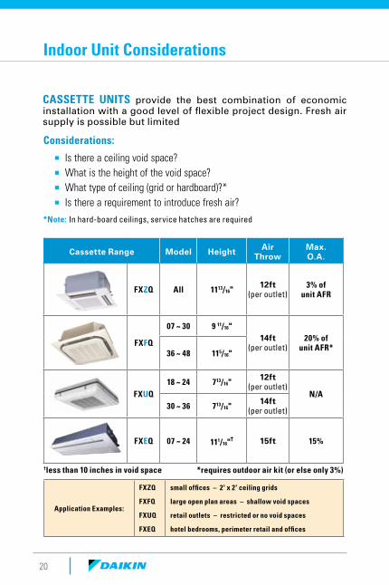
Cassette Range Model Height Air Throw
Max.O.A.
FXZQ All 1113/16"12ft
(per outlet)3% of
unit AFR
FXFQ
07 ~ 30 9 11/16"14ft
(per outlet)20% of
unit AFR*36 ~ 48 115/16"
FXUQ18 ~ 24 713/16"
12ft (per outlet)
N/A30 ~ 36 713/16"
14ft (per outlet)
FXEQ 07 ~ 24 111/16"† 15ft 15%
†less than 10 inches in void space *requires outdoor air kit (or else only 3%)
Application Examples:
FXZQ
FXFQ
FXUQ
FXEQ
small offices – 2' x 2' ceiling grids
large open plan areas – shallow void spaces
retail outlets – restricted or no void spaces
hotel bedrooms, perimeter retail and offices
CASSETTE UNITS provide the best combination of economic installation with a good level of flexible project design. Fresh air supply is possible but limited
Considerations:
¡ Is there a ceiling void space? ¡ What is the height of the void space? ¡ What type of ceiling (grid or hardboard)?* ¡ Is there a requirement to introduce fresh air?
*Note: In hard-board ceilings, service hatches are required
21
SP
ECIF
ICA
TIO
NS
& A
CC
ESS
OR
IES
SYSTEM
OV
ERVIEW
SYSTEM
SELECTIO
ND
ESIGN
OP
TIMIZA
TION
CON
TROLS A
ND
S
TAN
DA
RDS
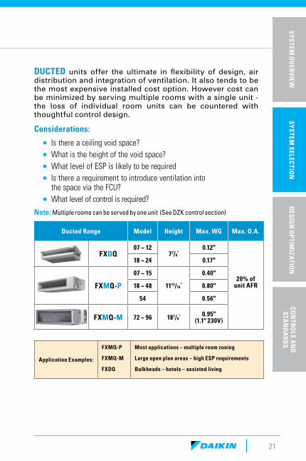
Ducted Range Model Height Max. WG Max. O.A.
FXDQ07 ~ 12
77/8"
0.12"
20% of unit AFR
18 ~ 24 0.17"
FXMQ-P
07 ~ 15
1113/16"
0.40"
18 ~ 48 0.80"
54 0.56"
FXMQ-M 72 ~ 96 181/8" 0.95"
(1.1" 230V)
Considerations:
¡ Is there a ceiling void space? ¡ What is the height of the void space? ¡ What level of ESP is likely to be required ¡ Is there a requirement to introduce ventilation into
the space via the FCU? ¡ What level of control is required?
Note: Multiple rooms can be served by one unit (See DZK control section)
Application Examples:
FXMQ-P
FXMQ-M
FXDQ
Most applications – multiple room zoning
Large open plan areas – high ESP requirements
Bulkheads – hotels – assisted living
DUCTED units offer the ultimate in flexibility of design, air distribution and integration of ventilation. It also tends to be the most expensive installed cost option. However cost can be minimized by serving multiple rooms with a single unit - the loss of individual room units can be countered with thoughtful control design.
22
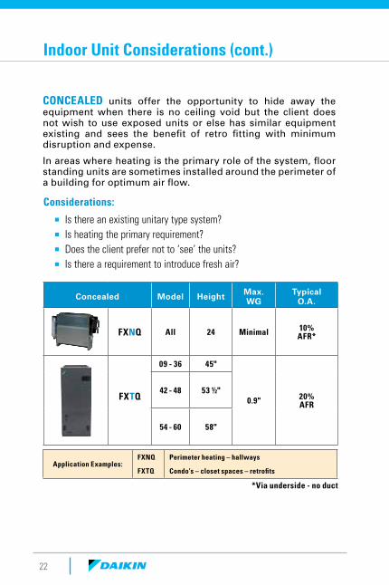
CONCEALED units offer the opportunity to hide away the equipment when there is no ceiling void but the client does not wish to use exposed units or else has similar equipment existing and sees the benefit of retro fitting with minimum disruption and expense.
In areas where heating is the primary role of the system, floor standing units are sometimes installed around the perimeter of a building for optimum air flow.
Concealed Model Height Max. WG
TypicalO.A.
FXNQ All 24 Minimal 10% AFR*
FXTQ
09 - 36 45"
0.9" 20% AFR
42 - 48 53 ½"
54 - 60 58"
Application Examples:FXNQ
FXTQ
Perimeter heating – hallways
Condo’s – closet spaces – retrofits
Considerations:
¡ Is there an existing unitary type system? ¡ Is heating the primary requirement? ¡ Does the client prefer not to ‘see’ the units? ¡ Is there a requirement to introduce fresh air?
*Via underside - no duct
Indoor Unit Considerations (cont.)
23
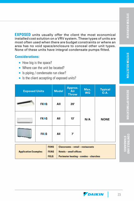
Exposed Units ModelApprox.
Air Throw
Max. WG
TypicalO.A.
FXHQ All 20'
N/A NONEFXAQ All 13'
FXLQ All 7'
Application Examples:
FXHQ
FXAQ
FXLQ
Classrooms – retail – restaurants
Hotels – small offices
Perimeter heating – condos – churches
EXPOSED units usually offer the client the most economical installed cost solution on a VRV system. These types of units are most often used when there are budget constraints or where an area has no void space/enclosure to conceal other unit types. None of these units have integral condensate pumps fitted.
Considerations:
¡ How big is the space? ¡ Where can the unit be located? ¡ Is piping / condensate run clear? ¡ Is the client accepting of exposed units?
SP
ECIF
ICA
TIO
NS
& A
CC
ESS
OR
IES
SYSTEM
OV
ERVIEW
SYSTEM
SELECTIO
ND
ESIGN
OP
TIMIZA
TION
CON
TROLS A
ND
S
TAN
DA
RDS
24
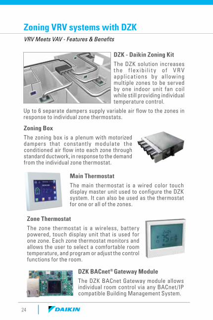
Zoning VRV systems with DZKVRV Meets VAV - Features & Benefits
DZK - Daikin Zoning KitThe DZK solution increases t he f lex ib i l i t y o f V R V applicat ions by allowing multiple zones to be served by one indoor unit fan coil while still providing individual temperature control.
Up to 6 separate dampers supply variable air flow to the zones in response to individual zone thermostats.
Main ThermostatThe main thermostat is a wired color touch display master unit used to configure the DZK system. It can also be used as the thermostat for one or all of the zones.
DZK BACnet® Gateway ModuleThe DZK BACnet Gateway module allows individual room control via any BACnet/IP compatible Building Management System.
Zoning BoxThe zoning box is a plenum with motorized dampers that constantly modulate the conditioned air flow into each zone through standard ductwork, in response to the demand from the individual zone thermostat.
Zone ThermostatThe zone thermostat is a wireless, battery powered, touch display unit that is used for one zone. Each zone thermostat monitors and allows the user to select a comfortable room temperature, and program or adjust the control functions for the room.
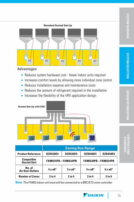
Ducted Set-Up with DZK
Standard Ducted Set-Up
25
Advantages
¡ Reduces system hardware cost - fewer Indoor units required ¡ Increases comfort levels by allowing more individual zone control ¡ Reduces installation expense and maintenance costs ¡ Reduces the amount of refrigerant required in the installation ¡ Increases the flexibility of the VRV application design
Zoning Box Range
Product Reference DZK030E4 DZK030E5 DZK048E4 DZK048E6
Compatible Ducted Unit FXMQ15PB ~ FXMQ24PB FXMQ30PB ~ FXMQ54PB
No. of Air Duct Outlets 4 x ø8" 5 x ø6" 4 x ø8" 6 x ø6"
Number of Zones 2 to 4 2 to 5 2 to 4 2 to 6
Note: The FXMQ indoor unit must still be connected to a BRC1E73 room controller
SP
ECIF
ICA
TIO
NS
& A
CC
ESS
OR
IES
SYSTEM
OV
ERVIEW
SYSTEM
SELECTIO
ND
ESIGN
OP
TIMIZA
TION
CON
TROLS A
ND
S
TAN
DA
RDS
26
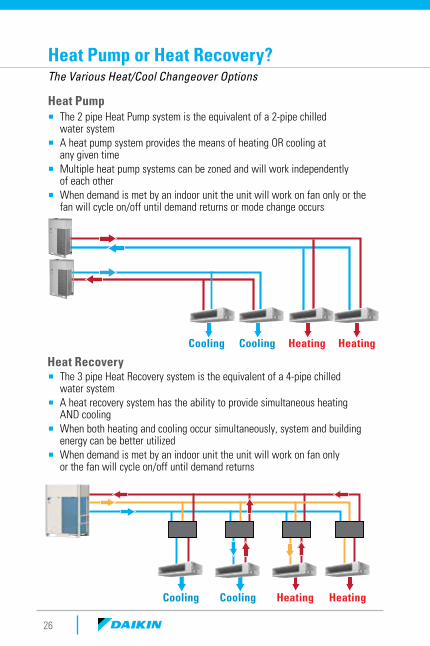
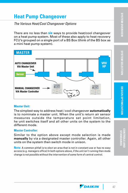
Heat Pump or Heat Recovery?The Various Heat/Cool Changeover Options
Cooling
Cooling
Cooling
Cooling
Heating
Heating
Heating
Heating
Heat Pump
Heat Recovery
¡ The 2 pipe Heat Pump system is the equivalent of a 2-pipe chilled water system
¡ A heat pump system provides the means of heating OR cooling at any given time
¡ Multiple heat pump systems can be zoned and will work independently of each other
¡ When demand is met by an indoor unit the unit will work on fan only or the fan will cycle on/off until demand returns or mode change occurs
¡ The 3 pipe Heat Recovery system is the equivalent of a 4-pipe chilled water system
¡ A heat recovery system has the ability to provide simultaneous heating AND cooling
¡ When both heating and cooling occur simultaneously, system and building energy can be better utilized
¡ When demand is met by an indoor unit the unit will work on fan only or the fan will cycle on/off until demand returns
Subarctic / Arctic
Very Cold
Cold
Mixed-Humid
Hot-Humid
Mixed-Dry
Hot-Dry
Marine
27
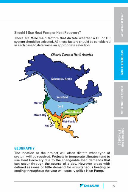
Should I Use Heat Pump or Heat Recovery?There are three main factors that dictate whether a HP or HR system should be selected. All these factors should be considered in each case to determine an appropriate selection:
GEOGRAPHY The location or the project will often dictate what type of system will be required. Projects in temperate climates tend to use Heat Recovery due to the changeable load demands that can occur through the course of a day. However areas with defined seasons or little demand for simultaneous heating or cooling throughout the year will usually utilize Heat Pump.
Climate Zones of North America
SP
ECIF
ICA
TIO
NS
& A
CC
ESS
OR
IES
SYSTEM
OV
ERVIEW
SYSTEM
SELECTIO
ND
ESIGN
OP
TIMIZA
TION
CON
TROLS A
ND
S
TAN
DA
RDS
Heating Heating Cooling Cooling Cooling Cooling CoolingHeating Heating Heating
HEATRECOVERY
HEATRECOVERY
HEATRECOVERY
28
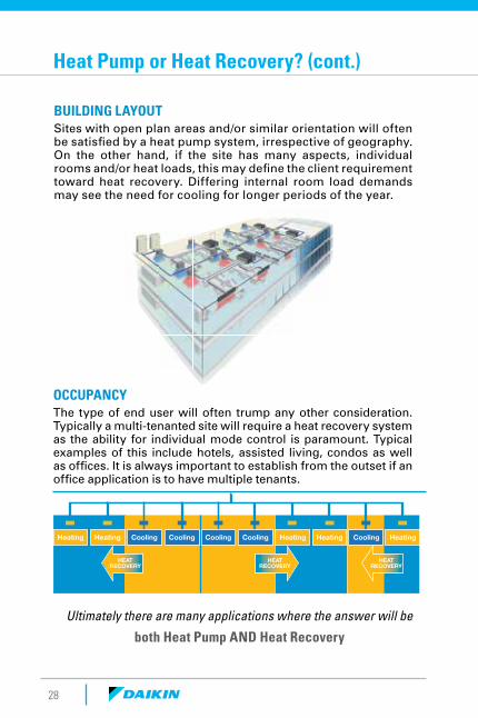
OCCUPANCY The type of end user will often trump any other consideration. Typically a multi-tenanted site will require a heat recovery system as the ability for individual mode control is paramount. Typical examples of this include hotels, assisted living, condos as well as offices. It is always important to establish from the outset if an office application is to have multiple tenants.
Ultimately there are many applications where the answer will be
both Heat Pump AND Heat Recovery
BUILDING LAYOUT Sites with open plan areas and/or similar orientation will often be satisfied by a heat pump system, irrespective of geography. On the other hand, if the site has many aspects, individual rooms and/or heat loads, this may define the client requirement toward heat recovery. Differing internal room load demands may see the need for cooling for longer periods of the year.
Heat Pump or Heat Recovery? (cont.)
29
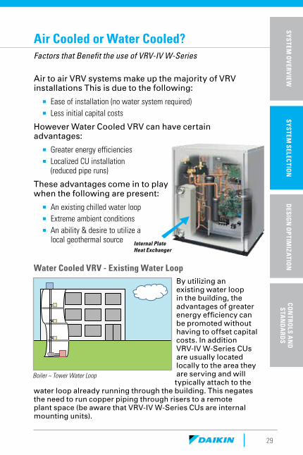
Air to air VRV systems make up the majority of VRV installations This is due to the following:
¡ Ease of installation (no water system required) ¡ Less initial capital costs
However Water Cooled VRV can have certain advantages:
¡ Greater energy efficiencies ¡ Localized CU installation
(reduced pipe runs)
These advantages come in to play when the following are present:
¡ An existing chilled water loop ¡ Extreme ambient conditions ¡ An ability & desire to utilize a
local geothermal source
Air Cooled or Water Cooled?Factors that Benefit the use of VRV-IV W-Series
Internal Plate Heat Exchanger
Water Cooled VRV - Existing Water LoopBy utilizing an existing water loop in the building, the advantages of greater energy efficiency can be promoted without having to offset capital costs. In addition VRV-IV W-Series CUs are usually located locally to the area they are serving and will typically attach to the
water loop already running through the building. This negates the need to run copper piping through risers to a remote plant space (be aware that VRV-IV W-Series CUs are internal mounting units).
Boiler ~ Tower Water Loop
SP
ECIF
ICA
TIO
NS
& A
CC
ESS
OR
IES
SYSTEM
OV
ERVIEW
SYSTEM
SELECTIO
ND
ESIGN
OP
TIMIZA
TION
CON
TROLS A
ND
S
TAN
DA
RDS
30
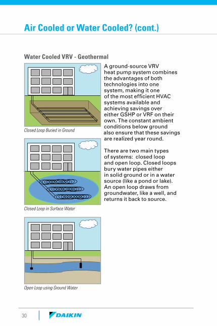
Water Cooled VRV - GeothermalA ground-source VRV heat pump system combines the advantages of both technologies into one system, making it one of the most efficient HVAC systems available and achieving savings over either GSHP or VRF on their own. The constant ambient conditions below ground also ensure that these savings are realized year round.
There are two main types of systems: closed loop and open loop. Closed loops bury water pipes either in solid ground or in a water source (like a pond or lake). An open loop draws from groundwater, like a well, and returns it back to source.
Closed Loop Buried in Ground
Closed Loop in Surface Water
Open Loop using Ground Water
Air Cooled or Water Cooled? (cont.)
31
Design Criteria: Water loop design is the responsibility of the engineer. However, two facts are needed from Daikin:
The minimum & maximum entering water temperatures:
¡ 50°F-113°F for Cooling ¡ 27°F-113°F for Cooling on a Geothermal System ¡ 50°F-113°F for Heating ¡ 14°F-95°F for Heating on a Geothermal System
A suitable water flow rate:
¡ 13.2gpm to 39gpm per module Boiler & Tower System ¡ 21gpm to 39gpm per module on a Geothermal System).
* (Be aware that conditions need to be met when EWT for heating is required below 50°F – seek assistance for these applications)
Other consideration:
¡ When VRV is to be applied with an open loop system, a 3rd party heat exchanger is required to ensure the plate heat exchanger of the VRV condensing unit operates in a closed loop system.
¡ The VRV condensing units have a heat output of approx. 2400btu’s. Where multiple units are placed in an enclosed area, any potential heat build up must be addressed (either with adequate ventilation or even a fan coil unit).
¡ From the CU pipe connection to the fan coils, the equipment, controls & selection process is identical to air cooled VRV.
SP
ECIF
ICA
TIO
NS
& A
CC
ESS
OR
IES
SYSTEM
OV
ERVIEW
SYSTEM
SELECTIO
ND
ESIGN
OP
TIMIZA
TION
CON
TROLS A
ND
S
TAN
DA
RDS
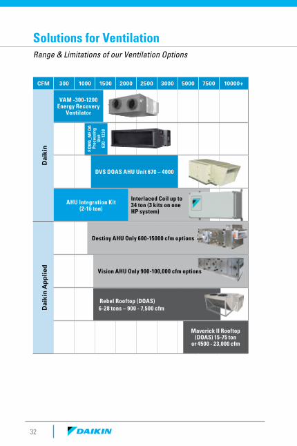
CFM 300 1000 1500 2000 2500 3000 5000 7500 10000+
Dai
kin
Dai
kin
Ap
plie
d
VAM -300-1200Energy Recovery
Ventilator
DVS DOAS AHU Unit 670 – 4000
AHU Integration Kit (2-16 ton)
Interlaced Coil up to 34 ton (3 kits on one HP system)
Destiny AHU Only 600-15000 cfm options
Vision AHU Only 900-100,000 cfm options
Rebel Rooftop (DOAS) 6-28 tons – 900 - 7,500 cfm
Maverick II Rooftop (DOAS) 15-75 ton
or 4500 - 23,000 cfm
FXM
Q_M
F O
A
Proc
essi
ng
Uni
t 63
0 –
1230
32
Solutions for VentilationRange & Limitations of our Ventilation Options
33
SP
ECIF
ICA
TIO
NS
& A
CC
ESS
OR
IES
SYSTEM
OV
ERVIEW
SYSTEM
SELECTIO
ND
ESIGN
OP
TIMIZA
TION
CON
TROLS A
ND
S
TAN
DA
RDS
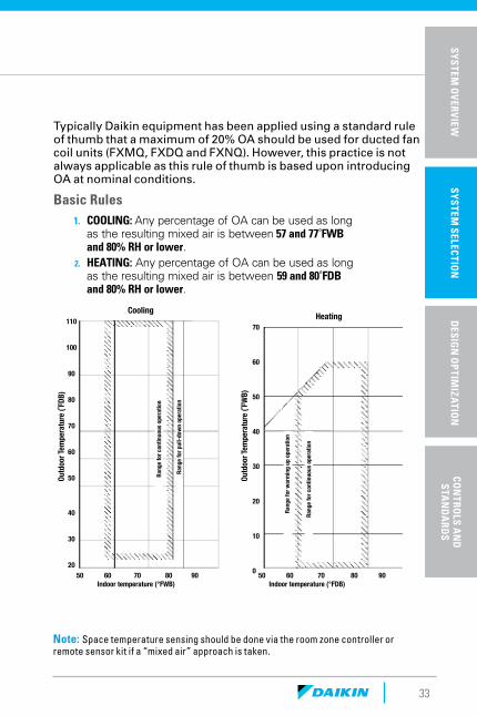
Typically Daikin equipment has been applied using a standard rule of thumb that a maximum of 20% OA should be used for ducted fan coil units (FXMQ, FXDQ and FXNQ). However, this practice is not always applicable as this rule of thumb is based upon introducing OA at nominal conditions.
Basic Rules1. COOLING: Any percentage of OA can be used as long
as the resulting mixed air is between 57 and 77˚FWB and 80% RH or lower.
2. HEATING: Any percentage of OA can be used as long as the resulting mixed air is between 59 and 80˚FDB and 80% RH or lower.
Cooling Heating
50 60 70 80 90 50 60 70 80 90 Indoor temperature (°FWB) Indoor temperature (°FDB)
70
60
50
40
30
20
10
0
110
100
90
80
70
60
50
40
30
20
Outd
oor T
empe
ratu
re (˚
FDB)
Outd
oor T
empe
ratu
re (˚
FWB)
Rang
e for
cont
inuo
us o
pera
tion
Rang
e for
war
min
g up
ope
ratio
n
Rang
e for
cont
inuo
us o
pera
tion
Rang
e for
pul
l-dow
n op
erat
ion
Note: Space temperature sensing should be done via the room zone controller or remote sensor kit if a “mixed air” approach is taken.
34
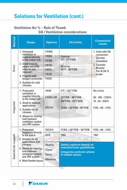
OA / Ventilation considerations
Met
ho
d
Scope Options EA Limits Connection Limits
Dire
ct
1. Untreated ventilation is supplied directly to the indoor unit
2. Small projects where low CFM volumes are required
3. Projects with budget constraints
4. Suitable for mild climates
FXMQ
FXDQ
FXNQ
FXTQ
FXFQ
FXZQ
FXEQ
Cooling: 57°–77°FWB
Heating: 59°F – 80°FDB
1. Units with OA connection (Ducted, Cassettes)
2. Consider Booster Fan & OA % scope
Inte
grat
ed
1. Pretreated ventilation is supplied directly to the indoor unit
2. Small to medium applications
3. Suitable for all climates
4. Allows for sharing load between ventilation system and VRV system
VAM
FXMQ-MF
EKEXV
5°F – 122° FDB
23°FDB – 90°FWB(50°FDB – 82°FWB)
FCBA = 50°FDB– 95°FDB
No Limits
50 - 100 - (130)%10 - 30 - (50)%
FCB = 90 - 110%
Sepa
rate
(de-
coup
led)
EKEXV FCBA = 50°FDB – 95°FDB FCB = 90 - 110%
DVS TBD TBD
Destiny
Vision
Rebel
Maverick
Select options based on manufacturer guidelines.
Integrate controls where it makes sense.
Solutions for Ventilation (cont.)
Ventilation Air % – Rule of Thumb
1. Pretreated ventilation directly to the space
2. Suitable for all applications and climates
3. Allows for sharing load between ventilation system and VRV system
4. Most flexible layout

DesignOptimization
36
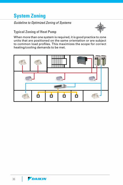
System ZoningGuideline to Optimized Zoning of Systems
Typical Zoning of Heat PumpWhen more than one system is required, it is good practice to zone units that are positioned on the same orientation or are subject to common load profiles. This maximizes the scope for correct heating/cooling demands to be met.
HP HP
37
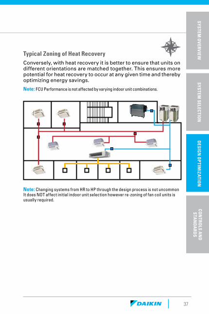
Typical Zoning of Heat RecoveryConversely, with heat recovery it is better to ensure that units on different orientations are matched together. This ensures more potential for heat recovery to occur at any given time and thereby optimizing energy savings.
Note: FCU Performance is not affected by varying indoor unit combinations.
Note: Changing systems from HR to HP through the design process is not uncommon It does NOT affect initial indoor unit selection however re-zoning of fan coil units is usually required.
HRHR
SP
ECIF
ICA
TIO
NS
& A
CC
ESS
OR
IES
SYSTEM
OV
ERVIEW
SYSTEM
SELECTIO
ND
ESIGN
OP
TIMIZA
TION
CON
TROLS A
ND
S
TAN
DA
RDS
38
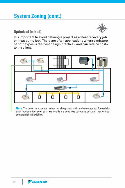
System Zoning (cont.)
Optimized (mixed)It is important to avoid defining a project as a ‘heat recovery job’ or ‘heat pump job’. There are often applications where a mixture of both types is the best design practice - and can reduce costs to the client.
HRHP
Note: The use of heat recovery does not always mean a branch selector box for each for each indoor unit or even each area – this is a good way to reduce costs further without compromising flexibility.
39
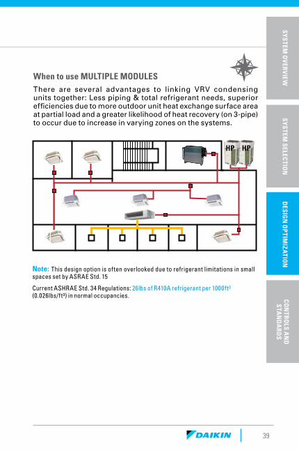
When to use MULTIPLE MODULESThere are several advantages to linking VRV condensing units together: Less piping & total refrigerant needs, superior efficiencies due to more outdoor unit heat exchange surface area at partial load and a greater likelihood of heat recovery (on 3-pipe) to occur due to increase in varying zones on the systems.
Note: This design option is often overlooked due to refrigerant limitations in small spaces set by ASRAE Std. 15
Current ASHRAE Std. 34 Regulations: 26lbs of R410A refrigerant per 1000ft³ (0.026lbs/ft³) in normal occupancies.
SP
ECIF
ICA
TIO
NS
& A
CC
ESS
OR
IES
SYSTEM
OV
ERVIEW
SYSTEM
SELECTIO
ND
ESIGN
OP
TIMIZA
TION
CON
TROLS A
ND
S
TAN
DA
RDS
HP HP
40
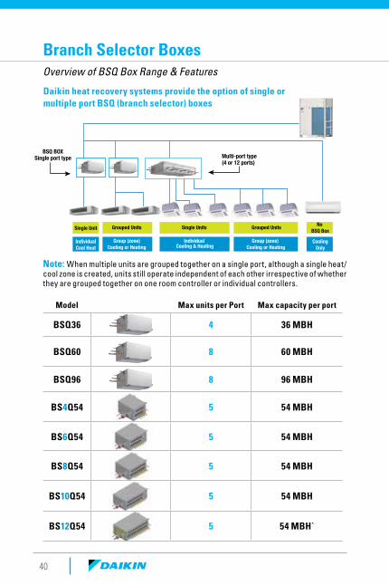
Multi-port type(4 or 12 ports)
BSQ BOXSingle port type
Single Unit Grouped Units Single Units Grouped Units No BSQ Box
IndividualCool Heat
Group (zone)Cooling or Heating
Individual Cooling & Heating
Group (zone) Cooling or Heating
CoolingOnly
Branch Selector BoxesOverview of BSQ Box Range & Features
Daikin heat recovery systems provide the option of single or multiple port BSQ (branch selector) boxes
Note: When multiple units are grouped together on a single port, although a single heat/cool zone is created, units still operate independent of each other irrespective of whether they are grouped together on one room controller or individual controllers.
Model Max units per Port Max capacity per port
BSQ36 4 36 MBH
BSQ60 8 60 MBH
BSQ96 8 96 MBH
BS4Q54 5 54 MBH
BS6Q54 5 54 MBH
BS8Q54 5 54 MBH
BS10Q54 5 54 MBH
BS12Q54 5 54 MBH`
SP
ECIF
ICA
TIO
NS
& A
CC
ESS
OR
IES
SYSTEM
OV
ERVIEW
SYSTEM
SELECTIO
ND
ESIGN
OP
TIMIZA
TION
CON
TROLS A
ND
S
TAN
DA
RDS
41
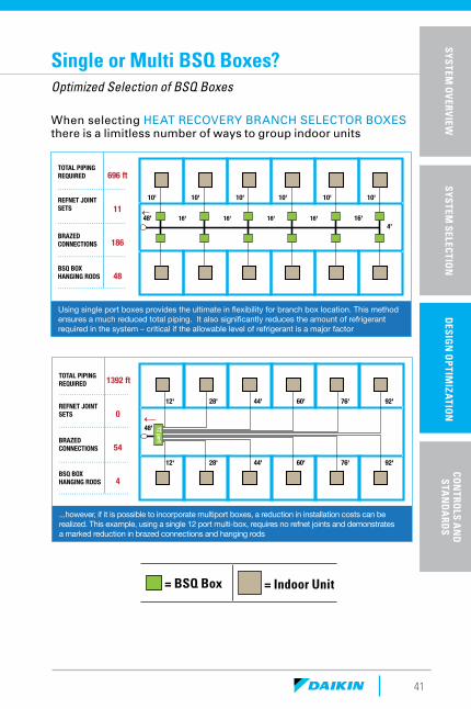
= BSQ Box = Indoor Unit
TOTAL PIPINGREQUIRED
REFNET JOINT SETS
BRAZED CONNECTIONS
BSQ BOXHANGING RODS
. . . . . . . . . . . . . . . . . . . . . . . . . . . . . . . .
. . . . . . . . . . . . . . . . . . . . . . . . . . . . . . . .
. . . . . . . . . . . . . . . . . . . . . . . . . . . . . . . .
. . . . . . . . . . . . . . . . . . . . . . . . . . . . . . . .
696 ft
11
186
48
Using single port boxes provides the ultimate in flexibility for branch box location. This method ensures a much reduced total piping. It also significantly reduces the amount of refrigerant required in the system – critical if the allowable level of refrigerant is a major factor
16' 16' 16' 16'48' 16'
10' 10' 10' 10' 10' 10'
4'
TOTAL PIPINGREQUIRED
REFNET JOINT SETS
BRAZED CONNECTIONS
BSQ BOXHANGING RODS
1392 ft
0
54
4
...however, if it is possible to incorporate multiport boxes, a reduction in installation costs can be realized. This example, using a single 12 port multi-box, requires no refnet joints and demonstrates a marked reduction in brazed connections and hanging rods
12' 28' 44' 60' 76' 92'
12' 28' 44' 60' 76' 92'
12 port
. . . . . . . . . . . . . . . . . . . . . . . . . . . . . . . .
. . . . . . . . . . . . . . . . . . . . . . . . . . . . . . . .
. . . . . . . . . . . . . . . . . . . . . . . . . . . . . . . .
. . . . . . . . . . . . . . . . . . . . . . . . . . . . . . . .
48'
Single or Multi BSQ Boxes?Optimized Selection of BSQ Boxes
When selecting HEAT RECOVERY BRANCH SELECTOR BOXES there is a limitless number of ways to group indoor units
42
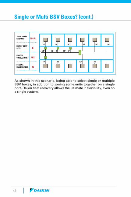
TOTAL PIPINGREQUIRED
REFNET JOINT SETS
BRAZED CONNECTIONS
BSQ BOXHANGING RODS
708 ft
8
102
20
4 port48'
10' 10' 10' 12' 28' 44'
8' 32' 12' 32'
16' 16'2' 2'
. . . . . . . . . . . . . . . . . . . . . . . . . . . . . . . .
. . . . . . . . . . . . . . . . . . . . . . . . . . . . . . . .
. . . . . . . . . . . . . . . . . . . . . . . . . . . . . . . .
. . . . . . . . . . . . . . . . . . . . . . . . . . . . . . . .
As shown in this scenario, being able to select single or multiple BSV boxes, in addition to zoning some units together on a single port, Daikin heat recovery allows the ultimate in flexibility, even on a single system.
Single or Multi BSV Boxes? (cont.)
SP
ECIF
ICA
TIO
NS
& A
CC
ESS
OR
IES
SYSTEM
OV
ERVIEW
SYSTEM
SELECTIO
ND
ESIGN
OP
TIMIZA
TION
CON
TROLS A
ND
S
TAN
DA
RDS
43
07
07 07 07 07 07 48
07 07 07 07 48
A A A A B
A A A A A B1 2 2 2 2 2 2 2 3 3
VRV IV HP
UNITSIZE
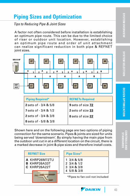
Piping Sizes and OptimizationTips to Reducing Pipe & Joint Sizes
A factor not often considered before installation is establishing an optimum pipe route. This can be due to the limited choice of riser or outdoor unit location. However, establishing an opt imum pipe route and order of uni t a t tachment can realize signif icant reduction in both pipe & REFNET joint sizes.
Piping Required* REFNETs Required
2 sets of - 3/4 & 5/8
7 sets of - 3/4 & 1/2
2 sets of - 3/4 & 3/8
0 sets of - 5/8 & 3/8
9 sets of size 72
2 sets of size 33
0 sets of size 22
REFNET Size Pipe Sizes*
A KHRP26M72TU B KHRP26A33T C KHRP26A22T
1 3/4 & 5/8 2 3/4 & 1/2 3 3/4 & 3/8 4 5/8 & 3/8
Shown here and on the following page are two options of piping connection for the same scenario. Pipes & joints are sized for units being served ‘downstream’. By simply having the main pipe from the outdoor unit cut in at a different location on the circuit, there is a marked decrease in joint & pipe sizes and therefore install costs.
*Pipes to fan coil not included
44
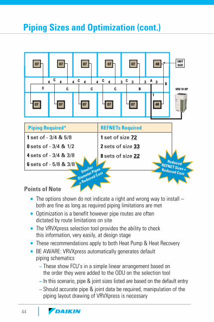
07 07 07 07 07 48
07 07 07 07 07 48
C C C C AB
C C C C B
4 4 4 4 4 4 3 3 3 3
1
VRV IV HP
UNITSIZE
Points of Note
¡ The options shown do not indicate a right and wrong way to install – both are fine as long as required piping limitations are met
¡ Optimization is a benefit however pipe routes are often dictated by route limitations on site
¡ The VRVXpress selection tool provides the ability to check this information, very easily, at design stage
¡ These recommendations apply to both Heat Pump & Heat Recovery ¡ BE AWARE: VRVXpress automatically generates default
piping schematics – These show FCU’s in a simple linear arrangement based on the order they were added to the ODU on the selection tool
– In this scenario, pipe & joint sizes listed are based on the default entry – Should accurate pipe & joint data be required, manipulation of the piping layout drawing of VRVXpress is necessary
Piping Required* REFNETs Required
1 set of - 3/4 & 5/8
0 sets of - 3/4 & 1/2
4 sets of - 3/4 & 3/8
6 sets of - 5/8 & 3/8
1 set of size 72
2 sets of size 33
8 sets of size 22
Piping Sizes and Optimization (cont.)
ReducedREFNET Sizes = Reduced CostSmaller
Diameter Pipes
= Reduced Cost
45
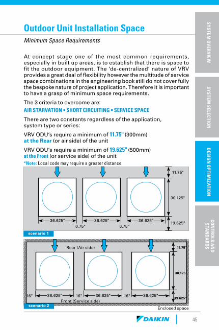
Outdoor Unit Installation SpaceMinimum Space Requirements
scenario 1
36.625" 36.625" 36.625"0.75” 0.75”
11.75"
30.125"
19.625"
At concept stage one of the most common requirements, especially in built up areas, is to establish that there is space to fit the outdoor equipment. The ‘de-centralized’ nature of VRV provides a great deal of flexibility however the multitude of service space combinations in the engineering book still do not cover fully the bespoke nature of project application. Therefore it is important to have a grasp of minimum space requirements.
The 3 criteria to overcome are:AIR STARVATION • SHORT CIRCUITING • SERVICE SPACE
There are two constants regardless of the application, system type or series:
VRV ODU’s require a minimum of 11.75" (300mm) at the Rear (or air side) of the unit
VRV ODU’s require a minimum of 19.625" (500mm) at the Front (or service side) of the unit*Note: Local code may require a greater distance
Rear (Air side)
36.625" 36.625" 36.625"16"16" 16"
11.75"
30.125"
19.625"
scenario 2Front (Service side)
Enclosed space
SP
ECIF
ICA
TIO
NS
& A
CC
ESS
OR
IES
SYSTEM
OV
ERVIEW
SYSTEM
SELECTIO
ND
ESIGN
OP
TIMIZA
TION
CON
TROLS A
ND
S
TAN
DA
RDS
46
The complexity of design comes in to play when multiple units are to be installed into a restrictive area. The space between units in scenario 1 above are minimal and is only required to avoid any possible issues of vibration.
However when wall heights exceed those shown in the data book (as they usually do) rather than move units away from the wall, the better practice (if the space allows) is to move the units further apart from each other. The distance can vary according to a number of factors however 16” between units will cover most all scenario’s.
Therefore, a great rule of thumb to see that a space is suitable for VRV equipment is: 12" x 16" x 20" Think of the service engineer!
¡ The minimum service space (20") allows for the removal of a compressor however if rows of units are to be located in one area then place the units front to front and allow 40" between each row (24" air side to air side).
¡ The minimum space between units of 0.75" can make removing the top plate awkward. If space allows, always leave at least 4" between units (although this is not a necessity).
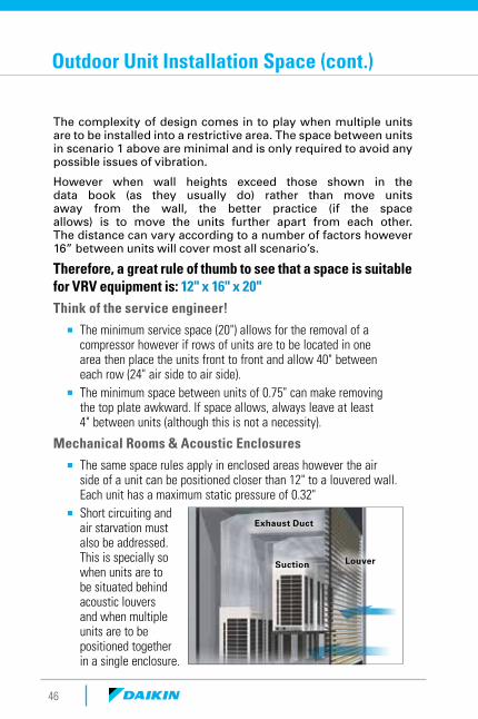
Mechanical Rooms & Acoustic Enclosures
¡ The same space rules apply in enclosed areas however the air side of a unit can be positioned closer than 12" to a louvered wall. Each unit has a maximum static pressure of 0.32"
¡ Short circuiting and air starvation must also be addressed. This is specially so when units are to be situated behind acoustic louvers and when multiple units are to be positioned together in a single enclosure.
Exhaust Duct
LouverSuction
Outdoor Unit Installation Space (cont.)
47
VRVHP
AUTO CHANGEOVERVIA Master Unit
MANUAL CHANGEOVERVIA Master Controller
Sensor
Heat Pump ChangeoverThe Various Heat/Cool Changeover Options
There are no less than six ways to provide heat/cool changeover on a heat pump system. Most of these also apply to heat recovery FCU’s grouped on a single port of a BS Box (think of the BS box as a mini heat pump system).
Master Unit:The simplest way to address heat / cool changeover automatically is to nominate a master unit. When the unit’s return air sensor measures outside the temperature set point limitation, he unit switches itself and all other units on the system to the different mode.
Master Controller:Similar to the option above except mode selection is made manually by via a designated master controller. Again, all other units on the system then switch mode in unison.
Note: A common pitfall is to elect an area that is not in constant use or has no easy access (e.g. managers office) In both options above, if the unit isn’t running then mode change is not possible without the intervention of some form of central control.
MASTER
SP
ECIF
ICA
TIO
NS
& A
CC
ESS
OR
IES
SYSTEM
OV
ERVIEW
SYSTEM
SELECTIO
ND
ESIGN
OP
TIMIZA
TION
CON
TROLS A
ND
S
TAN
DA
RDS
VRVHP
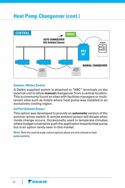
AUTO CHANGEOVERVIA Ambient Sensor
MANUAL CHANGEOVER
Sensor
Summer / Winter Switch:A Daikin supplied switch is attached to “ABC” terminals on the external unit to allow manual changeover from a central location. This is commonly found on sites with facilities managers or multi-tenant sites such as hotels where heat pump was installed in an exclusively cooling region.
3rd Part Ambient Sensor: This option was developed to provide an automatic version of the summer winter switch. A remote ambient sensor will dictate when mode change occurs. Occasionally used in temperate climates where budget constraints push the application towards heat pump but is an option rarely seen in this market.
Note: Both the central mode control options above are only utilized on heat pump systems.
CENTRAL
48
Heat Pump Changeover (cont.)
49
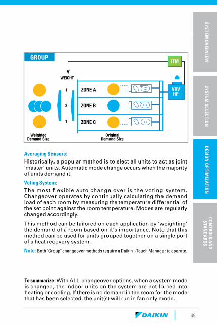
ZONE A
ZONE B
ZONE C
ITM
VRVHP
WEIGHT
1
3
1
WeightedDemand Size
OriginalDemand Size
Averaging Sensors: Historically, a popular method is to elect all units to act as joint ‘master’ units. Automatic mode change occurs when the majority of units demand it.
Voting System: The most flexible auto change over is the voting system. Changeover operates by continually calculating the demand load of each room by measuring the temperature differential of the set point against the room temperature. Modes are regularly changed accordingly.
This method can be tailored on each application by ‘weighting’ the demand of a room based on it’s importance. Note that this method can be used for units grouped together on a single port of a heat recovery system.
Note: Both "Group" changeover methods require a Daikin i-Touch Manager to operate.
SP
ECIF
ICA
TIO
NS
& A
CC
ESS
OR
IES
SYSTEM
OV
ERVIEW
SYSTEM
SELECTIO
ND
ESIGN
OP
TIMIZA
TION
CON
TROLS A
ND
S
TAN
DA
RDS
GROUP
To summarize: With ALL changeover options, when a system mode is changed, the indoor units on the system are not forced into heating or cooling. If there is no demand in the room for the mode that has been selected, the unit(s) will run in fan only mode.

Controls &Standards
52
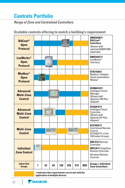
Controls PortfolioRange of Zone and Centralized Controllers
BACnet® Open
Protocol
DMS502B71 BACnet® Interface(Shown with optional DAM411B51 expander)
LonWorks® Open
Protocol
DMS504C71 LonWorks® Interface
Modbus® Open
Protocol
DTA116A51 Modbus® Adaptor (home automation/Modus)
Advanced Multi-Zone
Control
DCM601A71 Intelligent Touch Manager(Shown with Optional iTM Plus Adaptor)
Advanced Multi-Zone
Control
DCS601C71 Intelligent Touch Controller(Shown with Optional D3-Plus Adaptor)
Multi-Zone Control
DCS302C71 Centralized Remote ControlDCS302C71 x 2 for 128 Indoor Groups
Individual Zone Control
BRC1E73 Remote ControllerBRC2A71 Simplified Remote ControllerWireless Remote Controls
Indoor Unit Groups 1 16 64 128 256 512 1024 Groups = Individual
Zone Controllers
= Indicates that requirements can be met with the application of multiple devices
Scalable controls offering to match a building’s requirement
53
Project requirements drive the controls selection process
Project Requirements
Daikin VRV Controls
Simple individual zone control • •Independent Cool and Heat setpoints
•
Individual zone control with weekly programmable scheduling
•
Multi-zone control without scheduling functions • •Basic central point on/off control of all air handling units • •Multi-zone control of small to medium size projects • •Multi-zone control of large commercial projects •Advanced multi-zone control with scheduling logic and calendar
Automatic cooling/heating changeover for heat pump systems
•
Single input batch shutdown of all connected air handlers • •Web browser control and monitoring via Intranet and Internet
E-mail notification of system alarms and equipment malfunctions
Multiple tenant power billing for shared condenser applications
Temperature set-point range restrictions •
*Requires one or more DEC102A51-US2 Native application or feature Dependent upon capabilities of the third party energy management system Digital Input/Output units. for this device.
BRC1E73 Navigation
BRC2A71 Simplified
DCS302C71 Centralized
DCS301C71 Unified
SP
ECIF
ICA
TIO
NS
& A
CC
ESS
OR
IES
SYSTEM
OV
ERVIEW
SYSTEM
SELECTIO
ND
ESIGN
OP
TIMIZA
TION
CON
TROLS A
ND
S
TAN
DA
RDS
54
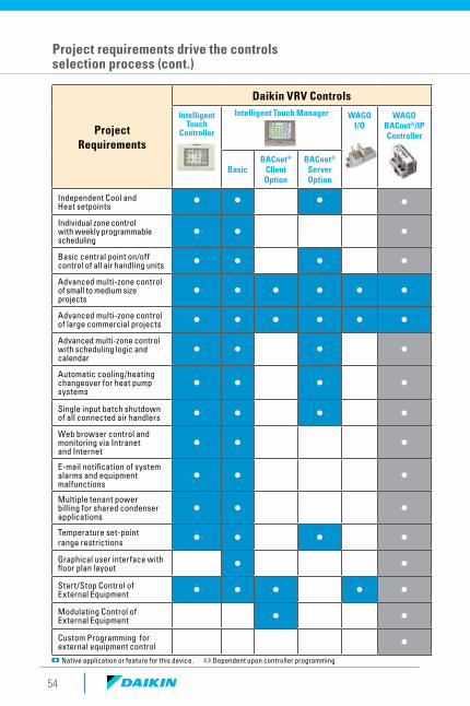
Project Requirements
Daikin VRV Controls
Intelligent Touch
Controller
Intelligent Touch Manager WAGOI/O
WAGO BACnet®/IPController
BasicBACnet®
Client Option
BACnet® Server Option
Independent Cool and Heat setpoints • • • •Individual zone control with weekly programmable scheduling
• • •
Basic central point on/off control of all air handling units • • • •Advanced multi-zone control of small to medium size projects
• • • • • •
Advanced multi-zone control of large commercial projects • • • • • •Advanced multi-zone control with scheduling logic and calendar
• • • • • •
Automatic cooling/heating changeover for heat pump systems
• • • • • •
Single input batch shutdown of all connected air handlers • • • • • •Web browser control and monitoring via Intranet and Internet
• • • • •
E-mail notification of system alarms and equipment malfunctions
• • • • •
Multiple tenant power billing for shared condenser applications
• • •
Temperature set-point range restrictions • • • • • •Graphical user interface with floor plan layout • • • •Start/Stop Control of External Equipment • • • • • •Modulating Control of External Equipment • • •Custom Programming for external equipment control •
Native application or feature for this device. Dependent upon controller programming
Project requirements drive the controls selection process (cont.)
55
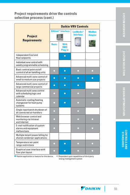
Project Requirements
Daikin VRV ControlsBACnet® Interface LonWorks®
InterfaceModbus Adaptor
Basic With BMS
Plug-in
Independent Cool and Heat setpoints • • •Individual zone control with weekly programmable scheduling • •Basic central point on/off control of all air handling units • • • •Advanced multi-zone control of small to medium size projects • • • •Advanced multi-zone control of large commercial projects • • • •Advanced multi-zone control with scheduling logic and calendar
• • • •Automatic cooling/heating changeover for heat pump systems
• • • •
Single input batch shutdown of all connected air handlers • • •Web browser control and monitoring via Intranet and Internet
• • •E-mail notification of system alarms and equipment malfunctions
• • •
Multiple tenant power billing for shared condenser applications • •Temperature set-point range restrictions • • • •Graphical user interface with floor plan layout • • • •
Native application or feature for this device. Dependent upon capabilities of third party energy management system
Project requirements drive the controls selection process (cont.)
SP
ECIF
ICA
TIO
NS
& A
CC
ESS
OR
IES
SYSTEM
OV
ERVIEW
SYSTEM
SELECTIO
ND
ESIGN
OP
TIMIZA
TION
CON
TROLS A
ND
S
TAN
DA
RDS
56
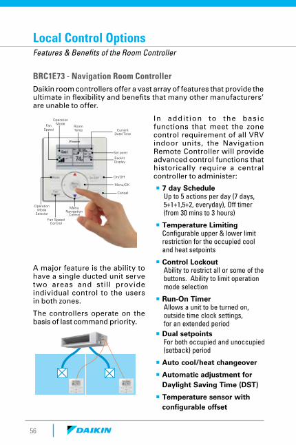
Local Control OptionsFeatures & Benefits of the Room Controller
BRC1E73 - Navigation Room Controller Daikin room controllers offer a vast array of features that provide the ultimate in flexibility and benefits that many other manufacturers’ are unable to offer.
Fan Speed
Operation Mode
Operation Mode
Selector
Room Temp
Menu Navigation
Fan Speed Control
Control
Current Date/Time
Set point
Backlit Display
On/Off
Menu/OK
Cancel
A major feature is the ability to have a single ducted unit serve two areas and still provide individual control to the users in both zones.
The controllers operate on the basis of last command priority.
¡ 7 day ScheduleUp to 5 actions per day (7 days, 5+1+1,5+2, everyday), Off timer (from 30 mins to 3 hours)
¡ Temperature Limiting Configurable upper & lower limit restriction for the occupied cool and heat setpoints
¡ Control LockoutAbility to restrict all or some of the buttons. Ability to limit operation mode selection
¡ Run-On TimerAllows a unit to be turned on, outside time clock settings, for an extended period
¡ Dual setpointsFor both occupied and unoccupied (setback) period
¡ Auto cool/heat changeover
¡ Automatic adjustment for Daylight Saving Time (DST)
¡ Temperature sensor with configurable offset
In addi t ion to the basic functions that meet the zone control requirement of all VRV indoor units, the Navigation Remote Controller will provide advanced control functions that historically require a central controller to administer:
57
Featured Controllers
SP
ECIF
ICA
TIO
NS
& A
CC
ESS
OR
IES
SYSTEM
OV
ERVIEW
SYSTEM
SELECTIO
ND
ESIGN
OP
TIMIZA
TION
CON
TROLS A
ND
S
TAN
DA
RDS
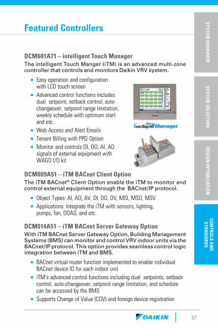
DCM601A71 – intelligent Touch ManagerThe intelligent Touch Manger (iTM) is an advanced multi-zone controller that controls and monitors Daikin VRV system.
¡ Easy operation and configuration with LCD touch screen
¡ Advanced control functions includes dual setpoint, setback control, auto-changeover, setpoint range limitation, weekly schedule with optimum start and etc.
¡ Web Access and Alert Emails ¡ Tenant Billing with PPD Option ¡ Monitor and controls DI, DO, AI, AO
signals of external equipment with WAGO I/O kit
DCM009A51 – iTM BACnet Client OptionThe iTM BACnet® Client Option enable the iTM to monitor and control external equipment through the BACnet/IP protocol.
¡ Object Types: AI, AO, AV, DI, DO, DV, MSI, MSO, MSV ¡ Applications: Integrate the iTM with sensors, lighting,
pumps, fan, DOAS, and etc.
DCM014A51 – iTM BACnet Server Gateway OptionWith iTM BACnet Server Gateway Option, Building Management Systems (BMS) can monitor and control VRV indoor units via the BACnet/IP protocol. This option provides seamless control logic integration between iTM and BMS.
¡ BACnet virtual router function implemented to enable individual BACnet device ID for each indoor unit
¡ iTM’s advanced control functions including dual setpoints, setback control, auto-changeover, setpoint range limitation, and schedule can be accessed by the BMS
¡ Supports Change of Value (COV) and foreign device registration
58
Featured Controllers (cont.)
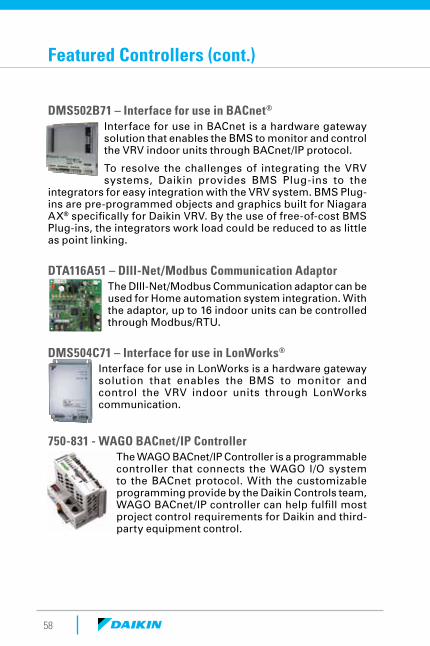
DMS502B71 – Interface for use in BACnet®
Interface for use in BACnet is a hardware gateway solution that enables the BMS to monitor and control the VRV indoor units through BACnet/IP protocol.
To resolve the challenges of integrating the VRV systems, Daikin provides BMS Plug-ins to the
integrators for easy integration with the VRV system. BMS Plug-ins are pre-programmed objects and graphics built for Niagara AX® specifically for Daikin VRV. By the use of free-of-cost BMS Plug-ins, the integrators work load could be reduced to as little as point linking.
DTA116A51 – DIII-Net/Modbus Communication AdaptorThe DIII-Net/Modbus Communication adaptor can be used for Home automation system integration. With the adaptor, up to 16 indoor units can be controlled through Modbus/RTU.
DMS504C71 – Interface for use in LonWorks®
Interface for use in LonWorks is a hardware gateway solution that enables the BMS to monitor and control the VRV indoor units through LonWorks communication.
750-831 - WAGO BACnet/IP ControllerThe WAGO BACnet/IP Controller is a programmable controller that connects the WAGO I/O system to the BACnet protocol. With the customizable programming provide by the Daikin Controls team, WAGO BACnet/IP controller can help fulfill most project control requirements for Daikin and third-party equipment control.

59
Codes & StandardsSome Key Considerations
CategoryKey Codes/Standards
Situation for VRV
Safety and Electrical
UL 1995Nat’l Electric CodeNFPA 90A, 90B
ASHRAE Std 15 Canada: B52
Daikin systems are UL 1995 certified.Install per NEC guidelines.Daikin systems comply via UL 1995. Std is applicable for APPLICATION, Not equipment.RcL not to exceed 26lbs/1000cuft (13lbs in restricted/institutional occupancies).
Efficiency & Performance
AHRI Std 1230ASHRAE Std 90.1
ASHRAE Std 62
Daikin VRV is tested and rated to AHRI Std 1230.Daikin VRV performance ratings exceed ASHRAE Std 90.1 2010.Daikin VRV systems can be configured to satisfy ASHRAE Std 62 (Ventilation, IAQ) requirements.
Federal Trade Commission
Buy American Act TradeAgreements Act
U.S. DOE has issued waiver for Ductless and VRV products.
All projects need to be confirmed through the Daikin legal dept. who can formally issue waiver notice and explanation for compliance purposes
Installation & Application
Int’l Building Code
Int’l Energy Conservation CodeInt’l Mechanical Code
Wind Loads – Use tie down drawingsSeismic – Use OSHPD certification
Economizer – Use optional accessoryInsulation – Use ¾” thick Armaflex
Condensate – Units with Pump & Float Switch are OK. Ductless units no need for secondary pan if level sensor used.Ventilation – similar to ASHRAE Std 62.Refrigeration – fittings used must be UL 1995 which Daikin’s are.
Local Code Code Adoption Varies
Local Code can introduce additional considerations on top of the national codes so always confirm requirements.
SP
ECIF
ICA
TIO
NS
& A
CC
ESS
OR
IES
SYSTEM
OV
ERVIEW
SYSTEM
SELECTIO
ND
ESIGN
OP
TIMIZA
TION
CON
TROLS A
ND
S
TAN
DA
RDS
60
Tips & Considerations
¡ Always refer to the Engineering Data, Installation Manual and Service Manual for detailed explanation and specification for VRV products.
¡ Utilize VRV Xpress selection software to ensure equipment selections are in accordance with all limitations and system capabilities.
¡ Maximize the use of Daikin City portal to auto generate submittal packages and streamline project management, update and quoting (where applicable).
¡ If a document says do SOMETHING – then do it, If it says DON’T DO SOMETHING – then DON’T do it.
¡ If a document is NOT telling you to do something – Then its NOT NECESSARY to do it (regardless of what might be normal for a U.S. piece of equipment).
¡ If it says ALWAYS REFER/COMPLY TO _____ CODE – then always refer/comply to _____ code – Local Codes when specified always trump installation instructions.
¡ Recommendations for optimum piping design (No Drier, 40” between REFNET etc) are not rules – they are recommendations that can help prevent issues in certain circumstances.
¡ If in doubt – never be afraid to ask and seek clarification
61
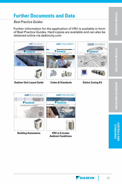
Further Documents and DataBest Practice Guides
CODES & STANDARDSAPPLICATION GUIDE
ENERGY-INTELLIGENT™ TECHNOLOGY HEATING AND COOLING SYSTEMS
APPLICATIONSIN EXTREME CLIMATE CONDITIONS
ENERGY-INTELLIGENT™ TECHNOLOGY HEATING AND COOLING SYSTEMS
Further information for the application of VRV is available in form of Best Practice Guides. Hard copies are available and can also be obtained online via daikincity.com
Outdoor Unit Layout Guide Codes & Standards
VRV in Extreme Ambient Conditions
Building Automation
Daikin Zoning Kit
SP
ECIF
ICA
TIO
NS
& A
CC
ESS
OR
IES
SYSTEM
OV
ERVIEW
SYSTEM
SELECTIO
ND
ESIGN
OP
TIMIZA
TION
CON
TROLS A
ND
S
TAN
DA
RDS
62
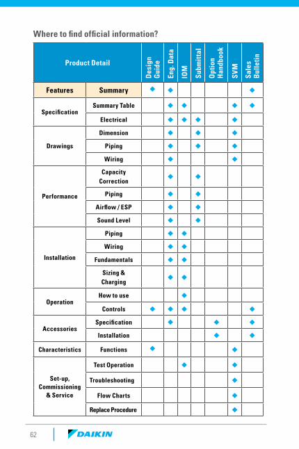
Where to find official information?
Product Detail
Des
ign
Gui
de
Eng.
Dat
a
IOM
Subm
itta
l
Opt
ion
Han
dboo
k
SVM
Sale
s B
ulle
tin
Features Summary ◆ ◆ ◆
SpecificationSummary Table ◆ ◆ ◆ ◆
Electrical ◆ ◆ ◆ ◆
Drawings
Dimension ◆ ◆ ◆
Piping ◆ ◆ ◆
Wiring ◆ ◆
Performance
Capacity Correction
◆ ◆
Piping ◆ ◆
Airflow / ESP ◆ ◆
Sound Level ◆ ◆
Installation
Piping ◆ ◆
Wiring ◆ ◆
Fundamentals ◆ ◆
Sizing & Charging
◆ ◆
OperationHow to use ◆
Controls ◆ ◆ ◆ ◆
AccessoriesSpecification ◆ ◆ ◆
Installation ◆ ◆
Characteristics Functions ◆ ◆
Set-up, Commissioning
& Service
Test Operation ◆ ◆
Troubleshooting ◆
Flow Charts ◆
Replace Procedure ◆

For more information:
Sales and Technical Support: 1-855-DAIKIN1
www.daikincomfort.com or daikinac.com
PM-DVRV 01-17
www.daikincity.com
Recommended