Abstract—Impairment of hand function is prevalent among
stroke survivors, motivating the search for effective
rehabilitation therapy. Recent studies have suggested that for
upper extremity functional recovery, repetitive training with
virtual reality is helpful. Repetitive training can be facilitated
with assistance from mechanical devices. Thus, we have
developed a training environment that integrates augmented
reality (AR) with assistive devices for post-stroke hand
rehabilitation. The AR element of our environment utilizes head
mounted display and virtual objects for reach-and-grasp task
training. The assistive device consists of either a body-powered
orthosis (BPO) or a pneumatic-powered device (PPD), both of
which are incorporated into gloves. This environment can be
easily set up and calibrated, is customizable for individual users,
and requires active user participation. Additionally, it can be
used with both real and virtual objects, as desired. We are
currently conducting pilot case studies to assess ease of use and
efficacy. At present, one stroke survivor from each of the three
training conditions, AR-with-BPO, AR-with-PPD and AR-only
(acting as the control), has completed the 6-week training
paradigm. Preliminary findings suggest user acceptance of the
technology and some potential for beneficial effects.
Keywords—Stroke, Hand Rehabilitation, Augmented Reality,
Assistive Device, Feedback Control.
I. INTRODUCTION
Stroke is among the leading causes of adult disability in
the United States [1,2,5]. Chronic impairment of the upper
extremity occurs in roughly one-third of all stroke survivors
[5]. While finger flexion often appears spontaneously within
weeks after a cerebrovascular accident, finger extension is
less likely to exhibit recovery [9] and creates difficulty for
voluntary hand opening. The resulting distal limb impairment
is especially problematic, since proper hand function is
crucial to carrying out activities of daily living. A study from
the UK reported that over half of the subjects studied
depended on others for assistance in ADLs six months
post-stroke [7].
Thus, a great need for hand rehabilitation therapies exists.
None of the current therapies, however, has been wholly
successful. For example, the effectiveness of electrical
stimulation may be reduced by hypertonia. Usage of
Botulinum toxin [6] further weakens already paretic muscles.
Participation in constraint-induced training [12] requires
some initial voluntary extension, thereby limiting eligible
stroke survivors.
A combination of two different technologies, however,
may be beneficial. The first is virtual reality (VR), which is
able to present pre-set or online computed rehabilitation tasks
with minimized setup and breakdown time. VR also provides
many important possibilities that are not possible in
real-world applications. For example, with precise hand
position tracking and kinetic calculations, a stroke survivor
user (“user” for short in the text hereafter) can manipulate
virtual objects that are free of mass but can still provide force
feedback. The second technology entails assistive devices.
Research has already shown that devices which permit the
active production of repetitive movements are helpful for arm
rehabilitation after stroke. Therapeutic straight-line reaching
assisted by the ARM Guide [8] resulted in improved active
range of motion and peak velocity. In another experiment,
assisted unilateral training with a PUMA robot led to
increased Fugl-Meyer Motor Assessment scores [10].
Similar results may be achievable with the hand. We know
of two systems which can readily provide assistance to finger
extension in coordination with VR: the Rutgers-II ND Hand
Master haptic device [14] and the CyberGrasp glove
(Immersion Inc.) [15]. There are some drawbacks with each.
With the Rutgers-II ND, the visual feedback is provided to
the user through VR displayed on a non-stereo desktop
monitor (“Fish Tank”). Thus, the user is unable to see his/her
real hand together with the virtual scene. Additionally, the
size of the virtual display is quite limited. Due to the use of
pneumatic pistons residing within the palmar space, the
maximal PIP flexion angle the glove allows is 45º, thereby
limiting grasp simulation. CyberGrasp is designed more for
haptic application purposes; its price and weight (over 500g)
are relatively prohibitive for clinical use.
Thus, we have developed a training environment that
integrates augmented reality (AR) and assistive devices. This
environment addresses the limitations of Rutgers-II ND and
CyberGrasp. AR allows the user to move objects with no
weight while seeing his/her own hand overlaid with the
virtual scene simultaneously. Our experience suggests that
see-through AR is much less disorienting to stroke survivors
than fully immersive VR. Also, by incorporating
head-tracking and stereoscopy, the virtual scene is made
panoramic rather than flat, as that of Fish Tank VR.
Assistance for finger extension is provided through either a
body-powered orthosis (BPO), with cables acting on the
dorsal side of the hand to pull the fingers, or a
pneumatic-powered device (PPD) with an air bladder on the
palmar side of the hand to push the fingers into extension.
The two assistive devices share some common favorable
characteristics: the pieces attached to the hand are lightweight
(less than 100g) gloves; they work with AR in a coordinated
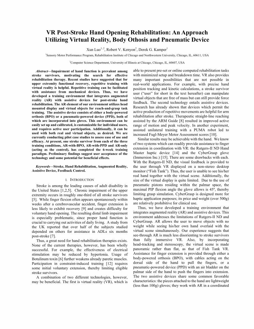
VR Post-Stroke Hand Opening Rehabilitation: An Approach
Utilizing Virtual Reality, Body Othosis and Pneumatic Device
Xun Luo1, 2, Robert V. Kenyon2, Derek G. Kamper1
1Sensory Motor Performance Program, Rehabilitation Institute of Chicago and Northwestern University, Chicago, IL, 60611, USA
2Computer Science Department, University of Illinois at Chicago, Chicago, IL, 60607, USA

manner; assistance is provided in accordance with a user’s
voluntary attempt and under the ultimate monitoring and
control of the therapist. This design diminishes the potential
for excessive assistance. Lastly, the monitoring/control
interface presented to the therapist incorporates visual, audio
and force feedback using commercial hardware.
In pilot experiments, two stoke survivors participated in
training under AR-with-BPO and AR-with-PPD conditions,
respectively. Another stroke survivor, acting as a control
subject, was trained with AR but no device assistance was
provided. While the control subject showed little
post-training improvement, both subjects under the integrated
environment showed some signs of quantitative and
qualitative improvements in hand function.
II. METHODOLOGY
A. Overview of The Training Environment
In our environment, the user is seated, wearing both head
mounted display (HMD) goggles and either the BPO or PPD.
The HMD shows 3D stereo virtual objects and contextual.
The user is then trained to perform grasp-and-release tasks of
virtual objects. Dynamic assistance of finger extension is
provided through the assistive device. For BPO, the
assistance is controlled by the voluntary movement of the
user’s unaffected arm; for PPD, assistance is controlled by a
combination of electromyography (EMG) signal along with
the difference between present hand opening angle and
desired hand opening angle. A therapist, who can be either
on-site with the user or watching off-site through a video
camera feed, supervises the user’s movement. The therapist
can modify the virtual scene dynamically to best meet the
needs of the user. An example on-site setup with BPO is
shown in Fig. 1.
Our environment is made up of four main components: AR
element, the BPO/PPD element, therapist monitor/control
element and a networking element interfacing the therapist
side and the user side.
B. The AR Element
Individual VR applications utilize one of four display
strategies: HMD, augmented display, Fish Tank and
projection-based display. Our user environment uses an
HMD display, namely, a SONY PLM-S700 Glasstron. The
Glasstron provides a horizontal view angle of 28º, simulates a
virtual 30” screen at 1.2 meters away from the viewer, and
has adjustable see-through using an LCD shutter system. It is
lightweight (120g for head device) and can be worn
comfortably by the user. By adjusting the see-through level,
the amount of the actual environment visible through the
goggles is altered. This allows the user to see his/her own
hand along with the virtual object.
The scene, as shown in Fig. 2, shows the surroundings as
well as the object to grasp. Proper perception of depth and
object size is achieved by both rich visual cues (e.g., table,
floor, stationary objects) and field stereo. Objects are
specially designed to have certain sizes and shapes. These
instruct the user as to the proper hand posture and opening
width needed for grasping. Also, objects can only be grasped
when the user’s hand contacts the virtual object’s surface at
“hotspots”. Hotspots are points predefined on the object’s
surface, at the location of normal grasping. They are invisible,
so the constraint they introduce is implicit to the user.
Fig. 1. On-site setup of the training environment using BPO. The therapist is
holding both the joystick and control switch (see section D) in his hands. (1):
HMD, (2): Fish Tank, (3): BPO.
Several software packages are used for building the AR
element. The Coin3D [Systems In Motion] library
implements scene graphs, and it provides a comprehensive
range of graphics and interactive objects. The CAVE Library
[VRCO, Inc.] manages display parameters to establish the
sense of depth and scale. The Trackd tool [VRCO, Inc.] reads
the magnetic head and hand trackers’ [Flock of Birds,
Ascension Tech] positions and orientations, and provides
these data to the rendering thread transparently.
Fig. 2. Overview of virtual object and surroundings displayed in HMD. (1):
Room, (2): Object, coke can, (3): Markers to provide 3D cues. Every object
is specially designed with a certain shape and size. Objects are chosen for
familiarity and interest to the user to improve motivation.
VR objects persist on hard disk in VRML format and map
one-to-one to files. We implement two levels of object
management to achieve scalability and flexibility. The first
(1)
(2)
(3)
(1)
(2)
(3)
level is “object library”. Each folder that contains object files
is scanned and an XML-format index file is generated for the
folder. The index file contains entries of each object’s size,
location, hotspot numbers, and other information like
suggested hand opening width. In this step, a “sanity check”
for the files is also done to ensure the index contains only
valid objects. The second level is “library view”, which
integrates all the libraries so that all objects appears to be in
one large repository, thus the details of individual libraries are
hidden and dynamic remapping is possible. Another
functionality the second level provides, as its name suggests,
is that the therapist can use his own definition file to create a
local “view” of the whole repository. These definition files
are plain text format and need only contain object names.
C. The Assistive Device Element
1) The BPO
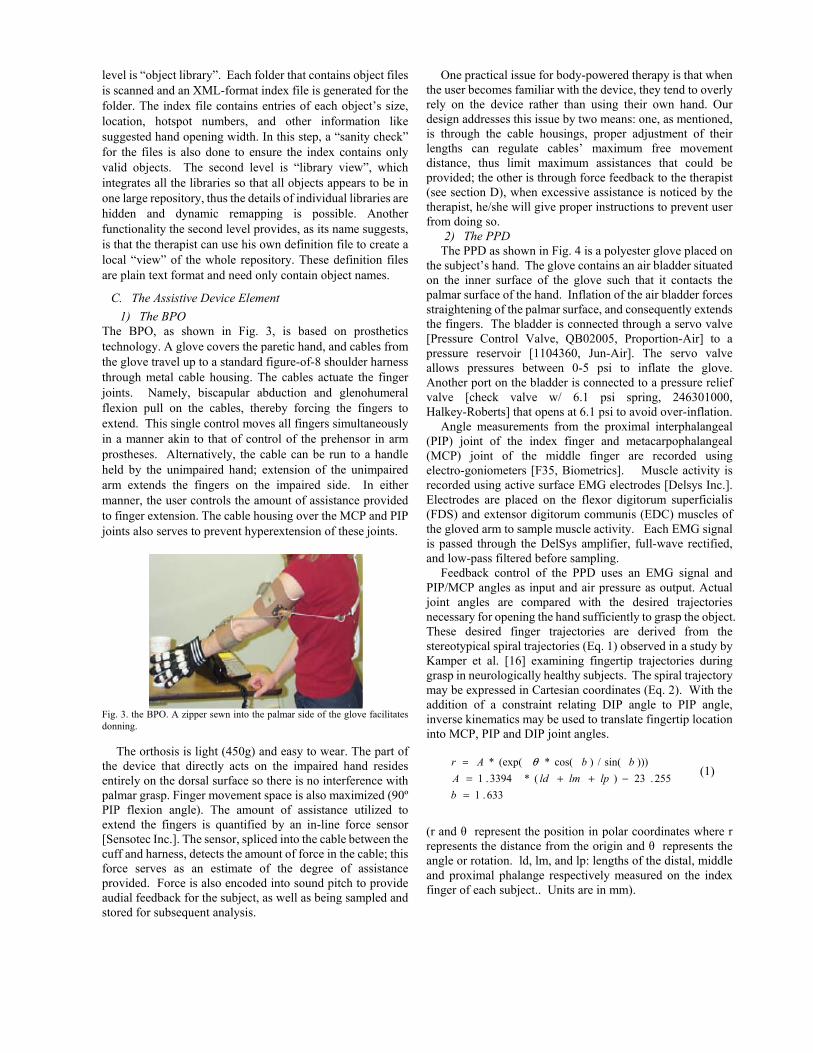
The BPO, as shown in Fig. 3, is based on prosthetics
technology. A glove covers the paretic hand, and cables from
the glove travel up to a standard figure-of-8 shoulder harness
through metal cable housing. The cables actuate the finger
joints. Namely, biscapular abduction and glenohumeral
flexion pull on the cables, thereby forcing the fingers to
extend. This single control moves all fingers simultaneously
in a manner akin to that of control of the prehensor in arm
prostheses. Alternatively, the cable can be run to a handle
held by the unimpaired hand; extension of the unimpaired
arm extends the fingers on the impaired side. In either
manner, the user controls the amount of assistance provided
to finger extension. The cable housing over the MCP and PIP
joints also serves to prevent hyperextension of these joints.
Fig. 3. the BPO. A zipper sewn into the palmar side of the glove facilitates
donning.
The orthosis is light (450g) and easy to wear. The part of
the device that directly acts on the impaired hand resides
entirely on the dorsal surface so there is no interference with
palmar grasp. Finger movement space is also maximized (90º
PIP flexion angle). The amount of assistance utilized to
extend the fingers is quantified by an in-line force sensor
[Sensotec Inc.]. The sensor, spliced into the cable between the
cuff and harness, detects the amount of force in the cable; this
force serves as an estimate of the degree of assistance
provided. Force is also encoded into sound pitch to provide
audial feedback for the subject, as well as being sampled and
stored for subsequent analysis.
One practical issue for body-powered therapy is that when
the user becomes familiar with the device, they tend to overly
rely on the device rather than using their own hand. Our
design addresses this issue by two means: one, as mentioned,
is through the cable housings, proper adjustment of their
lengths can regulate cables’ maximum free movement
distance, thus limit maximum assistances that could be
provided; the other is through force feedback to the therapist
(see section D), when excessive assistance is noticed by the
therapist, he/she will give proper instructions to prevent user
from doing so.
2) The PPD
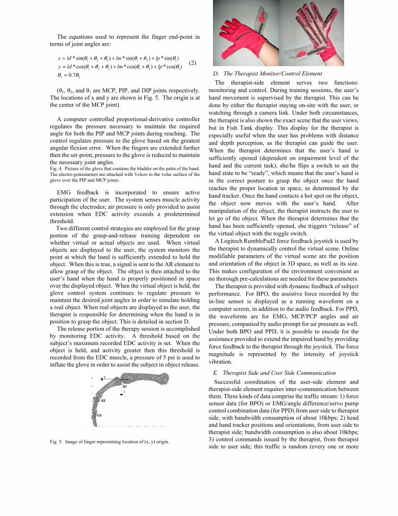
The PPD as shown in Fig. 4 is a polyester glove placed on
the subject’s hand. The glove contains an air bladder situated
on the inner surface of the glove such that it contacts the
palmar surface of the hand. Inflation of the air bladder forces
straightening of the palmar surface, and consequently extends
the fingers. The bladder is connected through a servo valve
[Pressure Control Valve, QB02005, Proportion-Air] to a
pressure reservoir [1104360, Jun-Air]. The servo valve
allows pressures between 0-5 psi to inflate the glove.
Another port on the bladder is connected to a pressure relief
valve [check valve w/ 6.1 psi spring, 246301000,
Halkey-Roberts] that opens at 6.1 psi to avoid over-inflation.
Angle measurements from the proximal interphalangeal
(PIP) joint of the index finger and metacarpophalangeal
(MCP) joint of the middle finger are recorded using
electro-goniometers [F35, Biometrics]. Muscle activity is
recorded using active surface EMG electrodes [Delsys Inc.].
Electrodes are placed on the flexor digitorum superficialis
(FDS) and extensor digitorum communis (EDC) muscles of
the gloved arm to sample muscle activity. Each EMG signal
is passed through the DelSys amplifier, full-wave rectified,
and low-pass filtered before sampling.
Feedback control of the PPD uses an EMG signal and
PIP/MCP angles as input and air pressure as output. Actual
joint angles are compared with the desired trajectories
necessary for opening the hand sufficiently to grasp the object.
These desired finger trajectories are derived from the
stereotypical spiral trajectories (Eq. 1) observed in a study by
Kamper et al. [16] examining fingertip trajectories during
grasp in neurologically healthy subjects. The spiral trajectory
may be expressed in Cartesian coordinates (Eq. 2). With the
addition of a constraint relating DIP angle to PIP angle,
inverse kinematics may be used to translate fingertip location
into MCP, PIP and DIP joint angles.
633.1
255.23)(*3394.1
)))sin(/)cos(*(exp(*
=
−++=
=
b
lplmldA
bbAr θ (1)
(r and θ represent the position in polar coordinates where r
represents the distance from the origin and θ represents the
angle or rotation. ld, lm, and lp: lengths of the distal, middle
and proximal phalange respectively measured on the index
finger of each subject.. Units are in mm).
The equations used to represent the finger end-point in
terms of joint angles are:
23
121321
121321
7.0
)cos(*)cos(*)cos(*
)sin(*)sin(*)sin(*
θθ
θθθθθθ
θθθθθθ
=
+++++=
+++++=
lplmldy
lplmldx (2)
(θ1, θ2, and θ3 are MCP, PIP, and DIP joints respectively.
The locations of x and y are shown in Fig. 5. The origin is at
the center of the MCP joint).
A computer controlled proportional-derivative controller
regulates the pressure necessary to maintain the required
angle for both the PIP and MCP joints during reaching. The
control regulates pressure to the glove based on the greatest
angular flexion error. When the fingers are extended further
then the set-point, pressure to the glove is reduced to maintain
the necessary joint angles. Fig. 4: Picture of the glove that contains the bladder on the palm of the hand.
The electro-goniometers are attached with Velcro to the volar surface of the
glove over the PIP and MCP joints.
EMG feedback is incorporated to ensure active
participation of the user. The system senses muscle activity
through the electrodes; air pressure is only provided to assist
extension when EDC activity exceeds a predetermined
threshold.
Two different control strategies are employed for the grasp
portion of the grasp-and-release training dependent on
whether virtual or actual objects are used. When virtual
objects are displayed to the user, the system monitors the
point at which the hand is sufficiently extended to hold the
object. When this is true, a signal is sent to the AR element to
allow grasp of the object. The object is then attached to the
user’s hand when the hand is properly positioned in space
over the displayed object. When the virtual object is held, the
glove control system continues to regulate pressure to
maintain the desired joint angles in order to simulate holding
a real object. When real objects are displayed to the user, the
therapist is responsible for determining when the hand is in
position to grasp the object. This is detailed in section D.
The release portion of the therapy session is accomplished
by monitoring EDC activity. A threshold based on the
subject’s maximum recorded EDC activity is set. When the
object is held, and activity greater then this threshold is
recorded from the EDC muscle, a pressure of 5 psi is used to
inflate the glove in order to assist the subject in object release.
Fig. 5: Image of finger representing location of (x, y) origin.
D. The Therapist Monitor/Control Element
The therapist-side element serves two functions:
monitoring and control. During training sessions, the user’s
hand movement is supervised by the therapist. This can be
done by either the therapist staying on-site with the user, or
watching through a camera link. Under both circumstances,
the therapist is also shown the exact scene that the user views,
but in Fish Tank display. This display for the therapist is
especially useful when the user has problems with distance
and depth perception, as the therapist can guide the user.
When the therapist determines that the user’s hand is
sufficiently opened (dependent on impairment level of the
hand and the current task), she/he flips a switch to set the
hand state to be “ready”, which means that the user’s hand is
in the correct posture to grasp the object once the hand
reaches the proper location in space, as determined by the
hand tracker. Once the hand contacts a hot spot on the object,
the object now moves with the user’s hand. After
manipulation of the object, the therapist instructs the user to
let go of the object. When the therapist determines that the
hand has been sufficiently opened, she triggers “release” of
the virtual object with the toggle switch.
A Logitech RumblePad2 force feedback joystick is used by
the therapist to dynamically control the virtual scene. Online
modifiable parameters of the virtual scene are the position
and orientation of the object in 3D space, as well as its size.
This makes configuration of the environment convenient as
no thorough pre-calculations are needed for these parameters.
The therapist is provided with dynamic feedback of subject
performance. For BPO, the assistive force recorded by the
in-line sensor is displayed as a running waveform on a
computer screen, in addition to the audio feedback. For PPD,
the waveforms are for EMG, MCP/PCP angles and air
pressure, companied by audio prompt for air pressure as well.
Under both BPO and PPD, it is possible to encode for the
assistance provided to extend the impaired hand by providing
force feedback to the therapist through the joystick. The force
magnitude is represented by the intensity of joystick
vibration.
E. Therapist Side and User Side Communication
Successful coordination of the user-side element and
therapist-side element requires inter-communication between
them. Three kinds of data comprise the traffic stream: 1) force
sensor data (for BPO) or EMG/angle difference/servo pump
control combination data (for PPD) from user side to therapist
side, with bandwidth consumption of about 10kbps; 2) head
and hand tracker positions and orientations, from user side to
therapist side; bandwidth consumption is also about 10kbps;
3) control commands issued by the therapist, from therapist
side to user side; this traffic is random (every one or more

seconds) and has negligible bandwidth consumption. To meet
the need for tele-rehabilitation, the bandwidth and response
time requirements must be able to be satisfied by the network.
Our environment’s overall bandwidth requirement is about
20-30kbps, and response requirement is about 8-10ms each
way (to meet the 100Hz sampling/control rate). These are all within the capability of today’s broadband network services: LAN,
DSL and T1.
F. Preliminary Experiment
Three male stroke survivors, rated between Stage 2-3 of the
Stage of Hand portion of the Chedoke-McMaster Stroke
Assessment scale [13] respectively, participated in training
sessions using the environment for 6 weeks. One of them was
using AR with BPO, one was using AR with PPD and one
was using only AR with no assistive device provided. The
30-minute training sessions were held three times per week.
In each session, the subject tried to grasp 15 virtual objects
followed by 15 real objects. The therapy was performed
on-site.
III. RESULTS
Subjects underwent standard functional tests, i.e. box &
blocks [11] and Rancho [4], before and after the six-week
training sessions. Both tests map better performance to higher
scores. Table 1 indicates that the subject undergoing
AR-with-BPO slightly improved scores on both box & blocks
and Rancho; the subject undergoing AR-with-PPD slightly
improved the Rancho score, but actually performed worse on
the box & blocks; the subject undergoing AR-only showed no
change in these scores.
Box&Blocks Rancho Treatment
Used Chedoke
Level Pre Post Pre Post
AR w/BPO 2 1 4 5 6 AR w/PPD 3 3 1 3 4 AR only 2 0 0 4 4
Table 1: Pre- and post-training functional test results of three stroke survivors
under different scheme of therapies.
Besides the functional tests, we used a custom-developed
apparatus to further assess the change of voluntary MCP
extension. Speed and maximum displacement were measured
for voluntary extension against no load. A servomotor
system, described in [13], maintained zero-load through
servo-control of the motor about zero torque.
The test results are shown in Table 2. The subject
undergoing AR-with-PPD showed some improvement in
both peak angular speed and angular displacement toward
extension. The subject undergoing AR-only exhibited
increase in peak velocity, but the amount of extension was so
small as to render it of little functional consequence. The
subject undergoing AR-with-BPO showed no change in
either measure.
Peak Angular
Velocity MCP Maximum
Displacement Treatment
Used Pre Post Pre Post
AR w/BPO 11.055 11.21 9.3388 10.5125
AR w/PPD 115.94 124.19 39.066 45.996
AR only 12.924 31.327 2.3323 4.7353 Table 2: Pre- and post-training values for peak MCP angular speed (in
degrees/second) and MCP maximum displacement (in degrees) during
voluntary extension.
An analysis was also performed on the assistive force data
collected from BPO over time. Fig. 6 shows the normalized
force during each training session. Assistive force first
increased largely from session 4 to session 6. This increase
may have arisen from greater patient familiarity with the
orthosis which allowed the patient to make greater use of it.
Starting from session 6, the needed assistive force started to
decrease, revealing a significant descending slope (p = 0.03).
The overall decrease is 14.5% from pre- to post-training.
0
2
4
6
8
10
12
14
16
1 2 3 4 5 6 7 8 9 10 11 12 13 14
Training Sessions
Force (lbs)
Maximum
Average
Fig. 6. Assistive forces recorded during each training session for
AR-with-BPO. Dashed line shows the fitted trend of average force.
IV. DISCUSSION AND CONCLUSIONS
In this paper, we present a training environment for
rehabilitation of hand opening in stroke survivors. This
environment integrates augmented reality, assistive devices
and the process of repetitive training of grasp-and-release
tasks. Compared with current hand rehabilitation robotic
devices, it is relatively low-cost and small in size, thus has the
potential for use in clinics and even at home. The networked
feature also allows application in tele-rehabilitation.
The preliminary experimental results, functional tests
scores, peak angular MCP extension speed, MCP maximal
displacement, and BPO assistive force, show that after 6
weeks of training, there was an encouraging trend of modest
improvement of finger extension capability in the impaired
hand. Both the user and therapist reported that the
environment was user friendly due to the lightness of the
assistive devices and the simple steps needed for set up of the
environment. We believe that therapies using this
environment are promising. Further studies to examine the
efficacy of the environment are ongoing.
V. ACKNOWLEDGMENT
This work was supported by grant H133E020724-03
(Rehabilitation Engineering Research Center) from the
National Institute on Disability and Rehabilitation Research
and by the Coleman Foundation.

REFERENCES
[1] D. G. Kamper, R. L. Harvey, S. Suresh and W.Z.Rymer, “Relative
Contributions of Neural Mechanisms Versus Muscle Mechanics in
Promoting Finger Extension Deficits Following Stoke”, Muscle &
Nerve, pp. 309-318, Sept. 2003.
[2] D. G. Kamper and W. Z. Rymer, “Impairment of Voluntary Control of
Finger Motion Following Stroke: Role of Inappropriate Muscle
Coactivation”, Muscle & Nerve, 24 pp. 673-681.
[3] C. Gowland, P. Stratford, M. Ward, J. Moreland, W. Torresin, S. Van
Hullenaar, J. Sanford, S. Barreca, B. Vanspall, and N. Plews,
“Measuring physical impairment and disability with the
Chedoke-McMaster Stroke Assessment,” Stroke, vol. 24, pp. 58-63,
1993.
[4] Jacobson-Sollerman C, Sperling L. “Grip function of the healthy hand
in a standardized hand function test. A study of the Rancho Los Amigos
test”, Scand J Rehabil Med. 1977;9(3):123-9..
[5] V.M. Parker, D.T. Wade, and R.L. Hewer, “Loss of arm function after
stroke: measurement, frequency, and recovery,” Int. Rehabil. Med., vol.
8, pp. 69-73, 1986
[6] B. B. Bhakta, J. A. Cozens, M. A. Chamberlain, J. M. Bamford, “Impact
of botulinum toxin type A on disability and carer burden due to arm
spasticity after stroke: a randomized double blind placebo controlled
trial”, J Neurol Neurosurg Psychiatry 2000:69, pp. 217-221.
[7] D.T. Wade, “The epidemiologically based needs assessment reviews.
Volume 1,” in. Health Care Needs Assessment, A. Stevens and J.
Raftery, editors, pp. 111-255, 1994.
[8] L. E. Kahn, M. Averbuch, W. Z. Rymer, D. J. Reinkensmeyer,
“Comparison of Robot-assisted Reaching to Free Reaching in
Promoting Recovery from Chronic Stroke”, Int. of Assisted Tech. in the
Information Age, Amsterdam, IOS Press, pp. 39-44, 2001.
[9] C. A. Trombly, Occupational Therapy for Physical Dysfunction,
Baltimore: Williams and Wilkins, pp. 454-471, 1989.
[10] C.G. Burgar, P.S. Lum, P.C. Shor, and M. Van der Loos, “Development
of robots for rehabilitation therapy: the Palo alto VA/Stanford
experience,” J. Rehab. Res. Develop, vol. 37: pp. 663-673, 2000.
[11] Desrosiers J, Bravo G, Hebert R, Dutil E, Mercier L. “Validation of the
Box and Block Test as a measure of dexterity of elderly people:
reliability, validity, and norms studies”, Arch Phys Med Rehabil. 1994
Jul;75(7):751-5.
[12] E. Taub and J. E. Crago, “Constraint induced movement therapy: a new
approach to treatment in physical rehabilitation,” Rehab. Psychol., vol.
43, pp. 152-170, 1998.
[13] D.G.Kamper, T.G.Hornby and W.Z.Rymer, “Extrinsic Flexor Muscles
Generate Concurrent Flexion of All Three Finger Joins”. J.
Biomechanics, 35 (2002) 1581–1589.
[14] A. S. Merians, D. Jack, R. Boian, M. Tremaine, G. C. Burdea, S.
Adamovich, M. Recce, and H. Poizner, "Virtual Reality-Augmented
Rehabilitation for Patients Following Stroke", Physical Therapy, Vol.
82(9), pp. 898-915, September 2002
[15] http://www.immersion.com/3d/products/cyber_grasp.php.
[16] D. G. Kamper, E. G. Cruz, M. P. Siegel, “Stereotypical Fingertip
Trajectories During Grasp”, J Neurophysiol, Vol 90, pp. 3702-3710,
2003
Recommended