VOLUMETRIC MIXER STANDARDS OF THE VOLUMETRIC MIXER MANUFACTURERS BUREAU
VMMB 100-01
First Edition – February 28, 2001
VMMB 100-01 February 28, 2001
NEED HELP??? It is the policy of the Bureau to make its services available to all specifying agencies on problems involving those specifications allied with volumetric mixer equipment. Requests for assistance can be made by contacting any Bureau member or the Executive Secretary of the Bureau at Bureau Headquarters in Silver Spring, Maryland. All problems involving specifications are then directed to the Chairman of the Bureau. If immediate action is not required, the Chairman includes the problem on the agenda for the next regularly scheduled Annual Bureau meeting. If the Chairman determines that immediate action is required, he designates two or more representatives from member companies to act on behalf of the Bureau and notifies all other member companies. Each member has the right to send one representative to meetings and conferences.
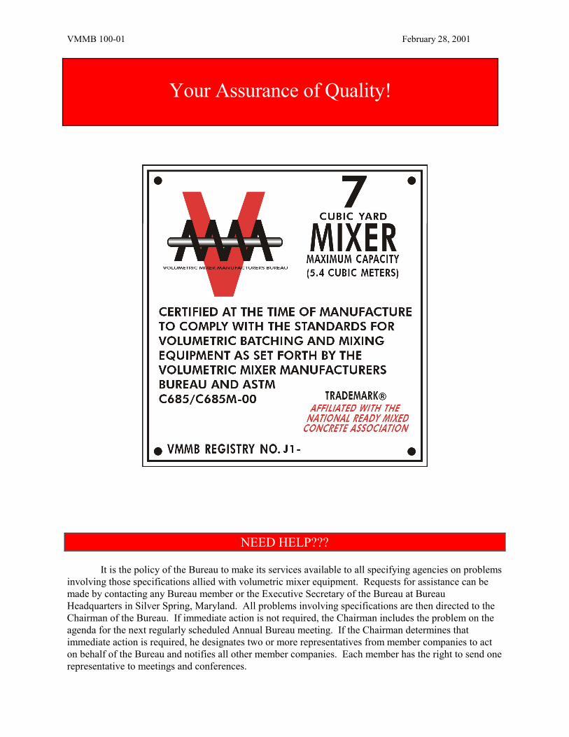
Your Assurance of Quality!
VMMB 100-01 February 28, 2001
Volumetric Mixer Standards of the Volumetric Mixer Manufacturers Bureau VMMB 100-01 First Edition – Effective February 28, 2001 Purpose These Standards have been prepared for the information of users of volumetric mixer equipment. They have been established pursuant to Article VII of the Bylaws of the Volumetric Mixer Manufacturers Bureau to describe and identify the products and combinations of products manufactured or furnished by members of the Bureau. These standards serve to define standardized rated capacities, the basis for determining rated capacities and a process for evaluating the uniformity of hydraulic cement concrete produced by these equipment. Effective Date These Standards shall become effective on February 28, 2001. Members of the Bureau shall attach rating plates to all eligible equipment and certified by them as complying with these Standards. Certification A copyrighted rating plate furnished by the Bureau shall be attached to volumetric mixer equipment shipped by a member of the Bureau and certified by the member as complying with these Standards. The rating plate shall define capacity and performance. Each member of the Bureau shall execute annually the following stipulation: “Our company hereby certifies that rating plates of the Volumetric Mixer Manufacturers Bureau have been attached to volumetric mixer equipment which conforms to the Standards of the Bureau and only to such eligible equipment.” This stipulation shall be signed by an authorized officer of the member company. Any member company shall furnish the Bureau, upon request, structural drawings, steel design computations and any other information pertinent to determining that items of equipment conform to these Standards. Scope These Standards specify requirements for volumetric mixer equipment eligible to be designated as standard by the Volumetric Mixer Manufacturers Bureau. Governing Units The values stated in inch-pound units are to be regarded as the standard. The metric equivalent values given in parenthesis are for information only.
3
VMMB 100-01 February 28, 2001
Equipment Specifications Volumetric Mixer Standards of the Volumetric Mixer Manufacturers Bureau Table of Contents 1. Specifications for Equipment 1.1. Bins, Silos or Tanks
1.1.1. Bins, Aggregate 1.1.2. Bins, Multiple Compartment
Aggregate 1.1.3. Bins, Cementitious Materials 1.1.4. Tanks, Water
1.2. Delivery Systems
1.2.1. Material Delivery System 1.2.2. Water Delivery System 1.2.3. Admixture Delivery System 1.2.4. Accuracy of Delivery Systems
1.3. Auger/Mixer 1.4 Standard Rated Unit Capacity
1.4.1. Bins for Aggregates 1.4.2. Bins or Silos for Cement 1.4.3. Tanks for Water
1.5 Production Rate 1.6 Uniformity Requirements
1.6.1. Sampling 1.6.2. Slump Testing 1.6.3. Air Content 1.6.4. Density (Unit Weight) 1.6.5. Air Free Density (Unit Weight) of
Concrete 1.6.6. Coarse Aggregate Content 1.6.7. Compressive Strength 1.6.8. Requirements for Mixing Uniformity
Qualifications 1.7 Reporting
1.7.1. Mixing Uniformity Evaluation 1.7.2. Standard Sizes 1.7.3. Approval 1.7.4. Rating Plates
1. SPECIFICATIONS FOR EQUIPMENT The following items of equipment are covered by these Standards and must meet the Standards in order for the entire unit to have a rating plate attached to it: ���� Bins for aggregates, ���� Bins for cementitious materials, ���� Tanks for water, ���� Material delivery systems, ���� Admixture delivery systems, ���� Augers/mixers. In addition, one size of volumetric mixer units of the same design and configuration shall have been evaluated and verified to meet the mixing uniformity requirements as outlined in these Standards to be eligible to carry a VMMB rating plate. 1.1. Bins, Silos or Tanks. A bin or tank shall consist of a suitable container for storing aggregates,
cementitious materials or water and, in the case of a bin for cementitious materials, such container shall have the capability of being sealed allowing protection from moisture.
4
VMMB 100-01 February 28, 2001
1.1.1. Bins, Aggregate. Aggregate bins shall be structurally designed to contain the minimum volume of normal weight aggregate as required for the rated capacity of the volumetric mixer unit, based on a material mass of 110 lbs/ft3 (1760 kg/m3). Bin capacity shall be stated in cubic feet and/or cubic meters of bin volume at the bin water level. Bin water level shall be the sum of water level volumes of each individual compartment in the bin above the metering device. Bin capacities may additionally be stated in tons and/or metric tons based on a material mass of 110 lb/ft3 (1760 kg/m3).
1.1.2. Bins, Multiple Compartment Aggregate. In addition to the requirements of Section 1.1.1, multiple compartment aggregate bins shall be structurally designed with dividers in place between compartments for different types or sizes of aggregates.
1.1.3. Bins or Silos, Cementitious Materials. Bins or silos for cementitious materials shall be structurally designed to contain the minimum volume of cementitious materials as required for rated capacity of the volumetric mixer unit, based on a material mass of 94 lb/ft3 (1506 kg/m3)**. Bin or silo capacity shall be stated in cubic feet and/or cubic meters of gross air volume of the bin or silo above the metering device. Bin or silo capacities may additionally be stated in tons and/or metric tons based on one cubic yard of partially aerated cement weighing 2000 lbs (one cubic meter of partially aerated cement weighing 1190 kg).
**NOTE: Structural design of bins or silos for cementitious materials is based on the bulk density of portland cement. Blended cements and supplementary cementing materials such as flyash, slag and silica fume will have different bulk density values. Rated capacity in mass units can be determined from the bulk density of these materials if the bins or silos are used to store them.
1.1.4. Tanks, Water. The minimum volume of the water tank shall be not less than the minimum volume required for the rated capacity of the volumetric mixer unit, stated in US gallons or liters.
1.2. Delivery Systems. All bins and tanks shall have devices such as counters, calibrated gate
openings or flowmeters available for controlling and determining the quantities of the ingredients discharged. These devices shall work together as a delivery system for ingredients.
Discharging devices shall be capable of stopping the flow of material within the specified tolerances in this Standard. Discharging devices shall not permit loss of material when stopped and shall be capable of controlling the rate of flow of the material.
Indicating devices that bear on the accuracy of proportioning and mixing of concrete shall be in full view and near enough to be read by the operator while concrete is being produced.
1.2.1. Material Delivery System. The controls that make up this system must be able to meet the required flow of materials regardless of the level of material in the storage bin, silo or tank. In addition, this system must be able to maintain set proportions of materials at all production rates. The delivery system must allow for calibration of the controls for each component separately.
1.2.2. Water Delivery System. The rate of water supplied to the continuous mixer shall be measured by a calibrated flowmeter coordinated with the cement and aggregate feeding mechanism, and with the mixer. The rate shall be capable of being adjusted in order to control slump at the desired levels and to ensure that the target water-cement ratios are being met. The device shall be so arranged that variable pressures in the water containment and delivery system will not affect the measurements.
5
VMMB 100-01 February 28, 2001
1.2.3. Admixture Delivery System. In addition to meeting the requirements stated in 1.2.1, an admixture delivery system shall also be sealed for moisture protection. In the case of a liquid admixture, the delivery system shall be sealed to protect against leaks.
1.2.4. Accuracy of Delivery Systems. The following tolerances for the various ingredients shall apply:
Cement, mass % 0 to +4 Fine aggregate, mass % ±2 Coarse aggregate, mass % ±2 Admixtures, mass or volume % ±3 Water, mass or volume % ±1
The tolerances are based on a volume/mass relationship established by calibration of the measuring devices furnished as an integral part of the whole equipment.
1.3. Auger/Mixer. The mixing device shall be of a type that will produce concrete at the required consistency and uniformity when operated at a rate indicated by the manufacturer.
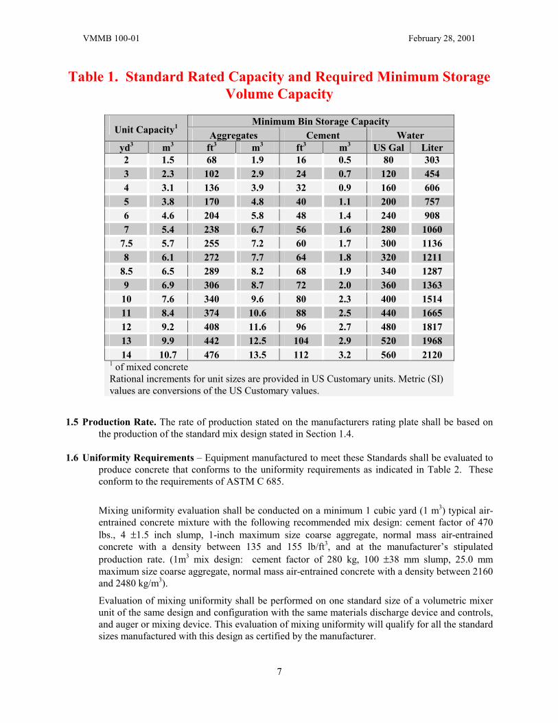
1.4. Standard Rated Unit Capacity. The rated unit capacity of the volumetric mixer unit shall be stated in cubic yards and/or cubic meters. The rated unit capacities shown in Table 1 shall be standard. No intermediate capacities shall be considered standard.
The criteria for establishing the rated volumetric unit capacity are based on minimum volumetric storage capacities for aggregates, cement and water to produce a standard 1 cubic yard mix design: cement factor of 470 lbs., 4 ±1.5 inch slump, 1-inch maximum size coarse aggregate, normal mass air-entrained concrete with a density between 135 and 155 lb/ft3 (1 m3 mix design: cement factor of 280 kg, 100 ±38 mm slump, 25.0 mm maximum size coarse aggregate, normal mass air-entrained concrete with a density between 2160 and 2480 kg/m3). Standard size units as indicated by the rated unit capacity shall have storage containers for ingredient materials of the minimum volume requirements as indicated in Table 1. Volumetric capacities may exceed the minimum requirements.
The volume of the bin shall be calculated on actual water level capacity above the discharge opening or metering device.
1.4.1. Bins for Aggregates. The minimum volume of aggregate storage capacity in cubic feet, calculated from dimensioned drawings shall be 34 times the rated unit capacity in cubic yards of concrete (in m3, 1.26 times the rated unit capacity in m3). The minimum volume shall be the sum of individual aggregate bins or a single aggregate bin with dividers.
1.4.2. Bins or Silos for Cement. The minimum volume of storage capacity for cement in cubic feet, calculated from dimensioned drawings, shall be 8 times the rated unit capacity in cubic yards of concrete (in m3, 0.296 times the rated unit capacity in m3).
1.4.3. Tanks for Water. The minimum volume of water tanks, calculated from dimensioned drawings, shall be 40 U.S. gallons per cubic yard of rated unit capacity of concrete (152 liters per m3).
6
VMMB 100-01 February 28, 2001
Table 1. Standard Rated Capacity and Required Minimum Storage Volume Capacity
Minimum Bin Storage Capacity
Unit Capacity1 Aggregates Cement Water yd3 m3 ft3 m3 ft3 m3 US Gal Liter 2 1.5 68 1.9 16 0.5 80 303 3 2.3 102 2.9 24 0.7 120 454 4 3.1 136 3.9 32 0.9 160 606 5 3.8 170 4.8 40 1.1 200 757 6 4.6 204 5.8 48 1.4 240 908 7 5.4 238 6.7 56 1.6 280 1060
7.5 5.7 255 7.2 60 1.7 300 1136 8 6.1 272 7.7 64 1.8 320 1211
8.5 6.5 289 8.2 68 1.9 340 1287 9 6.9 306 8.7 72 2.0 360 1363
10 7.6 340 9.6 80 2.3 400 1514 11 8.4 374 10.6 88 2.5 440 1665 12 9.2 408 11.6 96 2.7 480 1817 13 9.9 442 12.5 104 2.9 520 1968 14 10.7 476 13.5 112 3.2 560 2120
1 of mixed concrete Rational increments for unit sizes are provided in US Customary units. Metric (SI) values are conversions of the US Customary values.
1.5 Production Rate. The rate of production stated on the manufacturers rating plate shall be based on
the production of the standard mix design stated in Section 1.4.
1.6 Uniformity Requirements – Equipment manufactured to meet these Standards shall be evaluated to produce concrete that conforms to the uniformity requirements as indicated in Table 2. These conform to the requirements of ASTM C 685.
Mixing uniformity evaluation shall be conducted on a minimum 1 cubic yard (1 m3) typical air-entrained concrete mixture with the following recommended mix design: cement factor of 470 lbs., 4 ±1.5 inch slump, 1-inch maximum size coarse aggregate, normal mass air-entrained concrete with a density between 135 and 155 lb/ft3, and at the manufacturer’s stipulated production rate. (1m3 mix design: cement factor of 280 kg, 100 ±38 mm slump, 25.0 mm maximum size coarse aggregate, normal mass air-entrained concrete with a density between 2160 and 2480 kg/m3).
Evaluation of mixing uniformity shall be performed on one standard size of a volumetric mixer unit of the same design and configuration with the same materials discharge device and controls, and auger or mixing device. This evaluation of mixing uniformity will qualify for all the standard sizes manufactured with this design as certified by the manufacturer.
7
VMMB 100-01 February 28, 2001
1.6.1. Sampling – Take samples at approximately 15% and 85% of the discharge of the produced load of concrete by intercepting the full discharge stream. Obtain a minimum 1 cubic foot (28 L) sample from each portion of the load. Remix each sample with a shovel and protect from direct sunlight, rapid evaporation or contamination. Start tests on samples soon after they are obtained and complete testing as expeditiously as possible. Slump and air content tests should be started within 5 minutes and molding of cylinders for compressive strength determination should be started within 15 minutes after each sample was obtained.
1.6.2. Slump Testing – Perform the slump test in accordance with ASTM C 143. Start slump
test of each sample within 5 minutes after it is obtained.
1.6.3. Air Content – Determine the air content in accordance with ASTM C 231. ASTM C 173 should be used if concrete is made with structural lightweight aggregate.
1.6.4. Density (Unit Weight) – Use a container with a minimum volume of 0.2 cubic foot to
determine the density (unit weight) of concrete in accordance with ASTM C 138. Follow the requirements for minimum capacity of measure as indicated in ASTM C 138.
Calculate the density (unit weight) of the sample as follows:
W=M/V
Where: W is the measured density (unit weight) in lb/ft3 (kg/m3) M is the net mass of concrete in the container, lb. (kg) V is the volume of the container, ft3 (m3)
1.6.5. Air Free Density (Unit Weight) of Concrete
Calculate the air free density (unit weight) from the measured unit mass of each sample as follows:
Air free density (unit wt.) = 100 A)(100
W ×−
Where: W is the measured density (unit weight) in lb/ft3 (kg/m3) A is the air content measured in 1.6.3. on that sample, in percent
1.6.6. Coarse Aggregate Content – Use a convenient size container and obtain a sample of
approximately 40 lbs. (20 kg) of concrete. Wash the concrete sample over a No. 4 (4.75 mm) sieve sufficiently to remove the cement and most of the sand. Dry the material retained on the No. 4 (4.75 mm) sieve and determine its mass. The concrete used for the density (unit weight) measurement may also be used to determine the coarse aggregate content. Express the mass of the dry coarse aggregate as a percent of the mass of the original concrete sample as follows:
P = (c/b) x 100
Where: P = percent mass of coarse aggregate in concrete c = dry mass of aggregate retained on the No. 4 (4.75 mm) sieve b = mass of the sample of concrete
8
VMMB 100-01 February 28, 2001
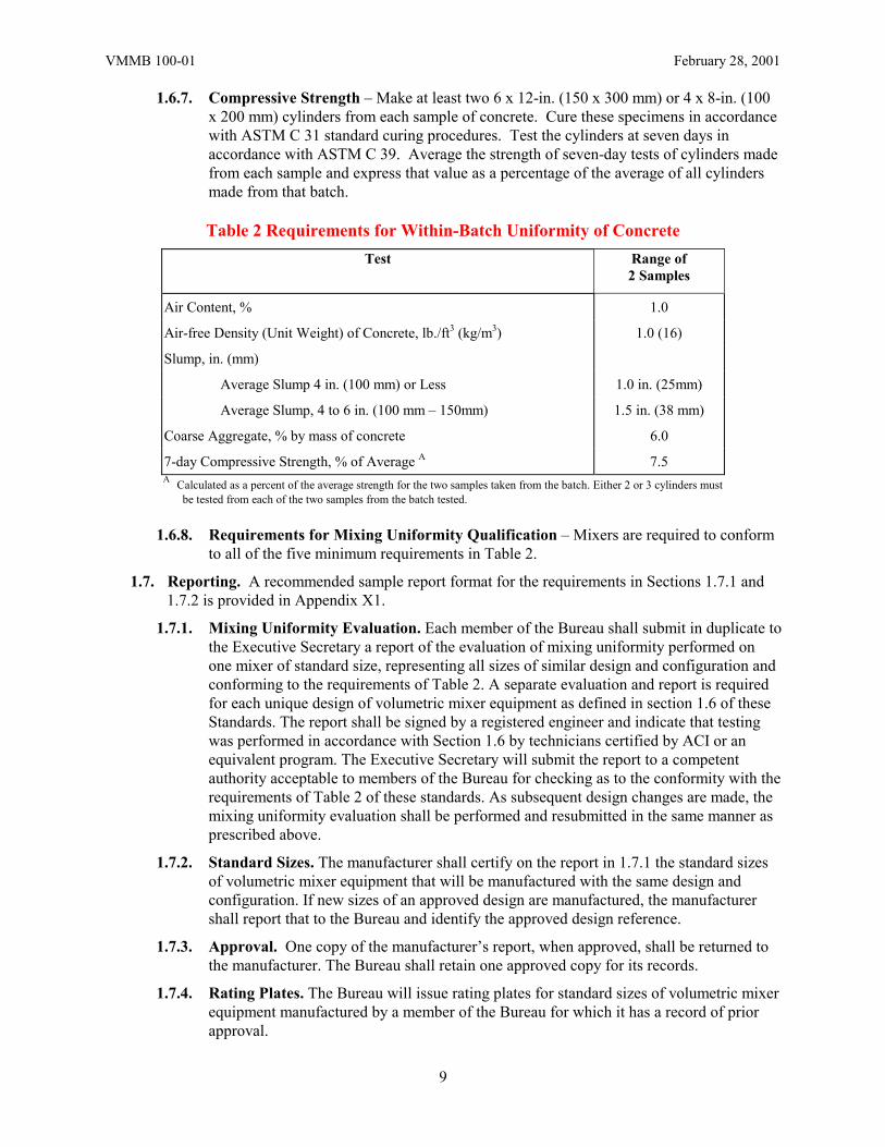
1.6.7. Compressive Strength – Make at least two 6 x 12-in. (150 x 300 mm) or 4 x 8-in. (100 x 200 mm) cylinders from each sample of concrete. Cure these specimens in accordance with ASTM C 31 standard curing procedures. Test the cylinders at seven days in accordance with ASTM C 39. Average the strength of seven-day tests of cylinders made from each sample and express that value as a percentage of the average of all cylinders made from that batch.
Table 2 Requirements for Within-Batch Uniformity of Concrete
Test Range of 2 Samples
Air Content, % 1.0
Air-free Density (Unit Weight) of Concrete, lb./ft3 (kg/m3) 1.0 (16)
Slump, in. (mm)
Average Slump 4 in. (100 mm) or Less 1.0 in. (25mm)
Average Slump, 4 to 6 in. (100 mm – 150mm) 1.5 in. (38 mm)
Coarse Aggregate, % by mass of concrete 6.0
7-day Compressive Strength, % of Average A 7.5 A Calculated as a percent of the average strength for the two samples taken from the batch. Either 2 or 3 cylinders must
be tested from each of the two samples from the batch tested.
1.6.8. Requirements for Mixing Uniformity Qualification – Mixers are required to conform to all of the five minimum requirements in Table 2.
1.7. Reporting. A recommended sample report format for the requirements in Sections 1.7.1 and 1.7.2 is provided in Appendix X1.
1.7.1. Mixing Uniformity Evaluation. Each member of the Bureau shall submit in duplicate to the Executive Secretary a report of the evaluation of mixing uniformity performed on one mixer of standard size, representing all sizes of similar design and configuration and conforming to the requirements of Table 2. A separate evaluation and report is required for each unique design of volumetric mixer equipment as defined in section 1.6 of these Standards. The report shall be signed by a registered engineer and indicate that testing was performed in accordance with Section 1.6 by technicians certified by ACI or an equivalent program. The Executive Secretary will submit the report to a competent authority acceptable to members of the Bureau for checking as to the conformity with the requirements of Table 2 of these standards. As subsequent design changes are made, the mixing uniformity evaluation shall be performed and resubmitted in the same manner as prescribed above.
1.7.2. Standard Sizes. The manufacturer shall certify on the report in 1.7.1 the standard sizes of volumetric mixer equipment that will be manufactured with the same design and configuration. If new sizes of an approved design are manufactured, the manufacturer shall report that to the Bureau and identify the approved design reference.
1.7.3. Approval. One copy of the manufacturer’s report, when approved, shall be returned to the manufacturer. The Bureau shall retain one approved copy for its records.
1.7.4. Rating Plates. The Bureau will issue rating plates for standard sizes of volumetric mixer equipment manufactured by a member of the Bureau for which it has a record of prior approval.
9
VMMB 100-01 February 28, 2001
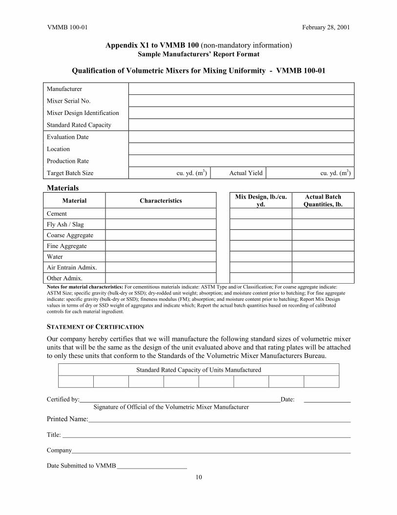
Appendix X1 to VMMB 100 (non-mandatory information) Sample Manufacturers’ Report Format
Qualification of Volumetric Mixers for Mixing Uniformity - VMMB 100-01
Manufacturer
Mixer Serial No.
Mixer Design Identification
Standard Rated Capacity
Evaluation Date
Location
Production Rate
Target Batch Size cu. yd. (m3) Actual Yield cu. yd. (m3)
Materials Material Characteristics Mix Design, lb./cu.
yd. Actual Batch Quantities, lb.
Cement
Fly Ash / Slag
Coarse Aggregate
Fine Aggregate
Water
Air Entrain Admix.
Other Admix. Notes for material characteristics: For cementitious materials indicate: ASTM Type and/or Classification; For coarse aggregate indicate: ASTM Size; specific gravity (bulk-dry or SSD); dry-rodded unit weight; absorption; and moisture content prior to batching; For fine aggregate indicate: specific gravity (bulk-dry or SSD); fineness modulus (FM); absorption; and moisture content prior to batching; Report Mix Design values in terms of dry or SSD weight of aggregates and indicate which; Report the actual batch quantities based on recording of calibrated controls for each material ingredient. STATEMENT OF CERTIFICATION
Our company hereby certifies that we will manufacture the following standard sizes of volumetric mixer units that will be the same as the design of the unit evaluated above and that rating plates will be attached to only these units that conform to the Standards of the Volumetric Mixer Manufacturers Bureau.
Standard Rated Capacity of Units Manufactured
Certified by: Date: Signature of Official of the Volumetric Mixer Manufacturer
Printed Name:
Title:
Company
Date Submitted to VMMB
10
VMMB 100-01 February 28, 2001
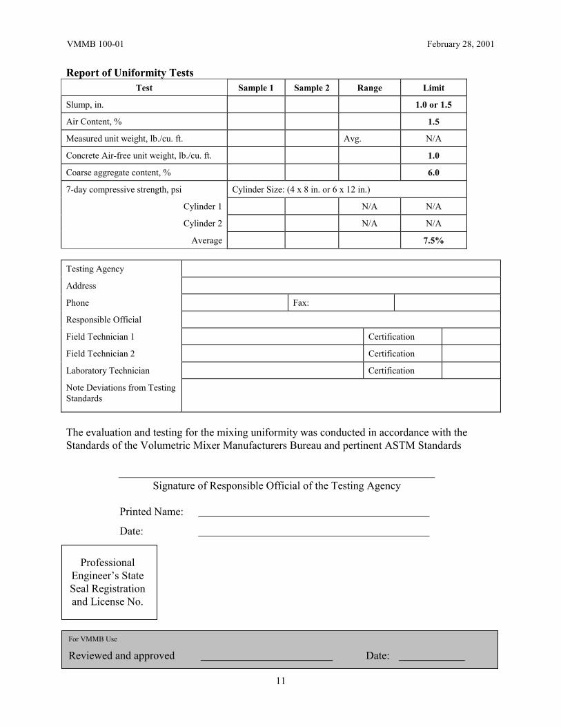
Report of Uniformity Tests Test Sample 1 Sample 2 Range Limit
Slump, in. 1.0 or 1.5
Air Content, % 1.5
Measured unit weight, lb./cu. ft. Avg. N/A
Concrete Air-free unit weight, lb./cu. ft. 1.0
Coarse aggregate content, % 6.0
7-day compressive strength, psi Cylinder Size: (4 x 8 in. or 6 x 12 in.)
Cylinder 1 N/A N/A
Cylinder 2 N/A N/A
Average 7.5% Testing Agency
Address
Phone Fax:
Responsible Official
Field Technician 1 Certification
Field Technician 2 Certification
Laboratory Technician Certification
Note Deviations from Testing Standards
The evaluation and testing for the mixing uniformity was conducted in accordance with the Standards of the Volumetric Mixer Manufacturers Bureau and pertinent ASTM Standards
Signature of Responsible Official of the Testing Agency
Printed Name:
Date:
11
Professional Engineer’s State Seal Registration and License No.
For VMMB Use
Reviewed and approved Date:
Volumetric Mixer Manufacturers Bureau Member Companies
(As of February 22, 2005)
Cemen Tech, Inc. Indianola, Iowa
Custom-Crete, Inc.
Dallas, Texas
Elkin Manufacturing, Inc. Indiana, Pennsylvania
Reimer International, Inc. Didsbury, Alberta, Canada
Zimmerman Industries Ephrata, Pennsylvania
Volumetric Mixer Manufacturers Bureau 900 Spring Street, Silver Spring, MD 20910 USA
Phone 301-587-1400 * Fax 301-587-1605 www.vmmb.org
Recommended