Presented to you byStructural Engineer
Mohamed Galal Mohamed Nour El Din2014
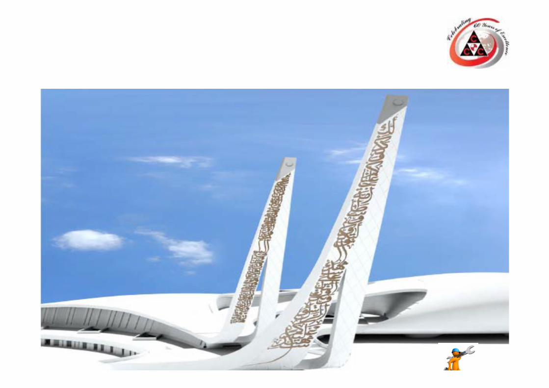
QATAR FACULTY OF ISLAMIC STUDIES
QFIS and structural challengesVIP Lounge
Introduction :‐
‐I would like to extend my thanks first to Allah who gave me the chance to work in this project and second to our management who believed in me.
‐This presentation will cover two items carried internally in QFIS project.A‐VIP Lounge Curved wall supporting system.B‐Ablution Walkway and VIP Lounge bulkhead and drywall.
A. VIP Lounge Curved wall supporting system.
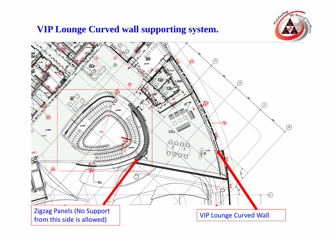
VIP Lounge Curved wall supporting system.
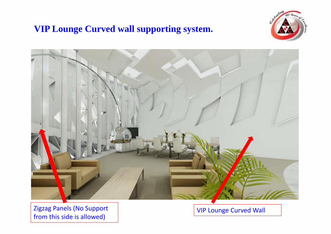
VIP Lounge Curved WallZigzag Panels (No Support from this side is allowed)
VIP Lounge Curved WallZigzag Panels (No Support from this side is allowed)
VIP Lounge Curved wall supporting system.
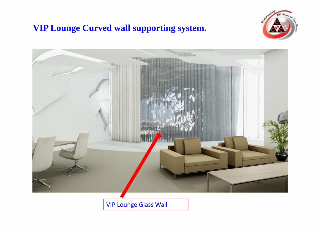
VIP Lounge Glass Wall
VIP Lounge Curved wall supporting system.
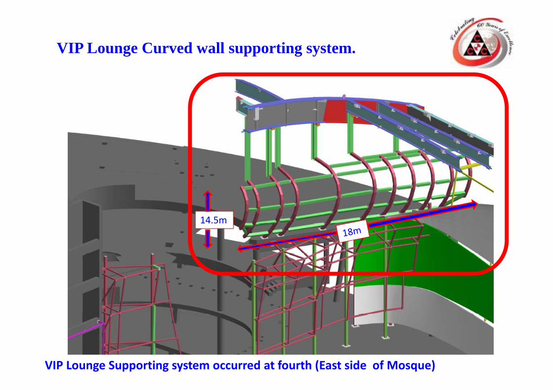
VIP Lounge Supporting system occurred at fourth (East side of Mosque)
14.5m
VIP Lounge Curved wall supporting system.
VIP Lounge Curved wall supporting system.
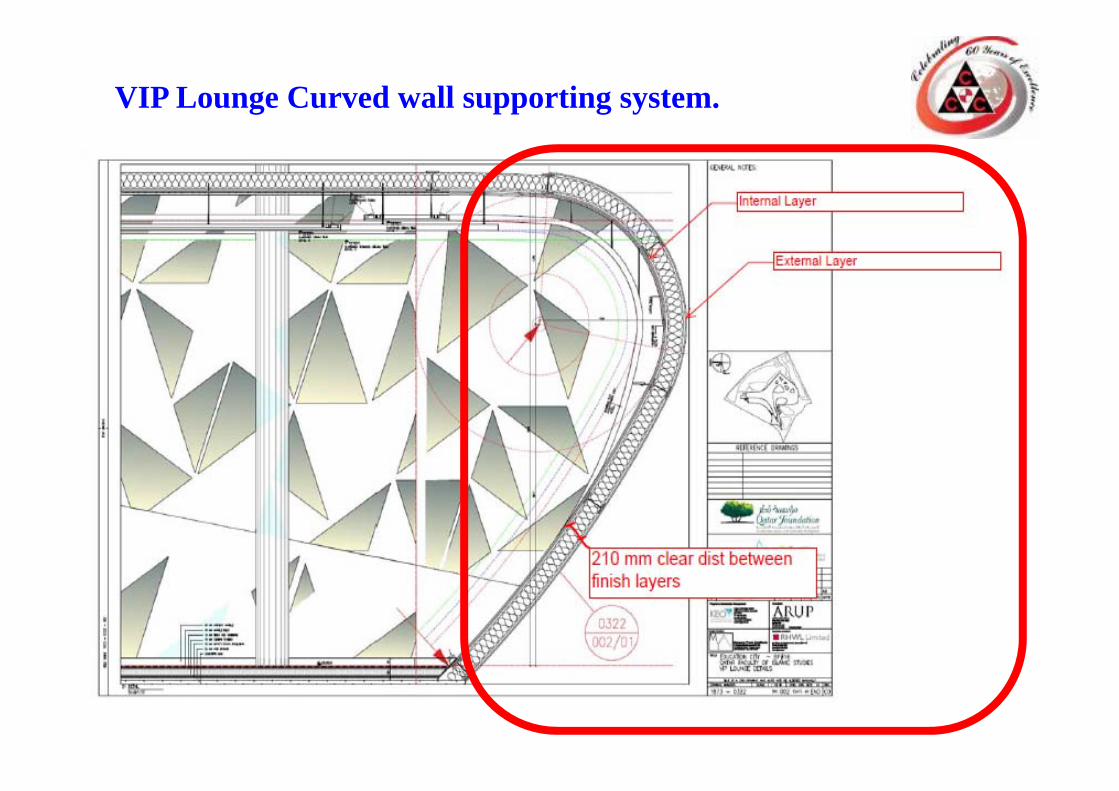
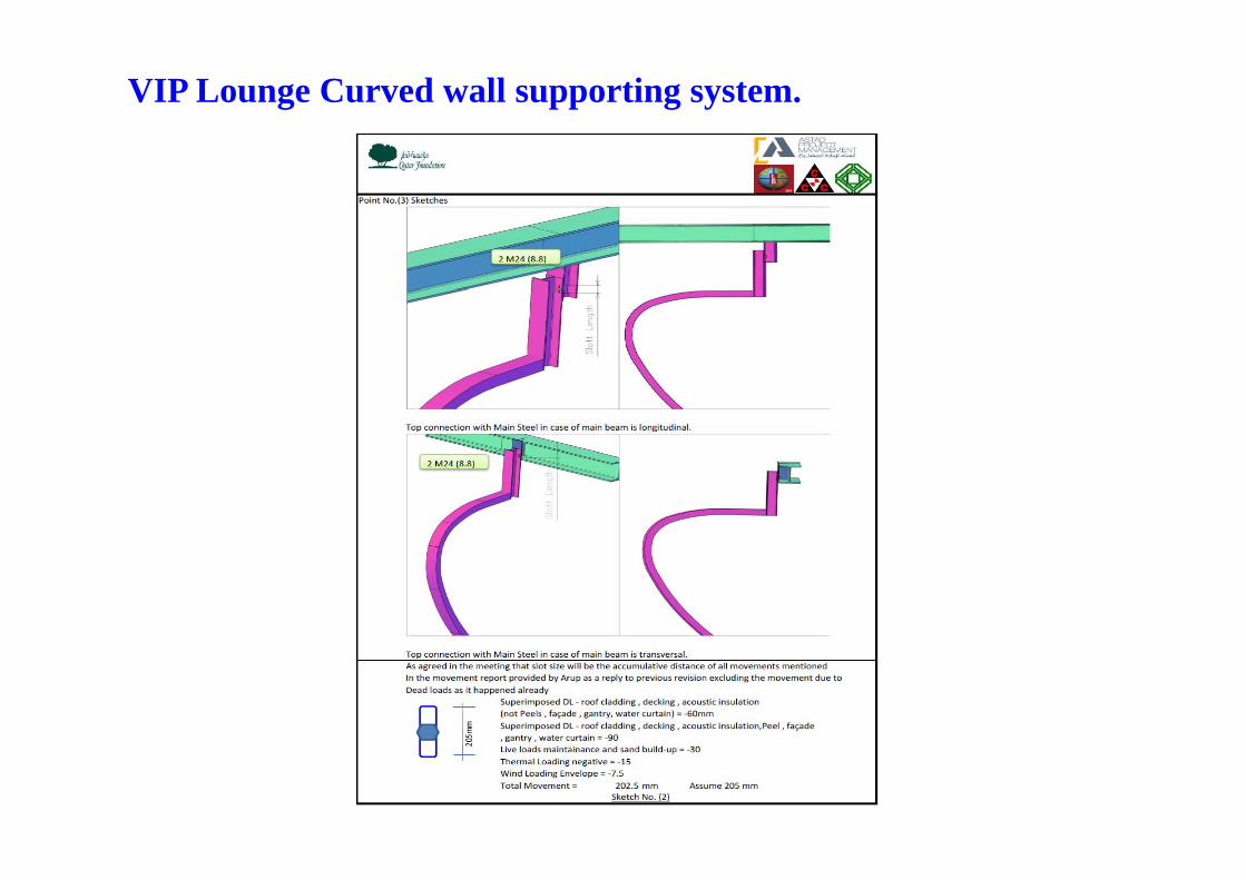
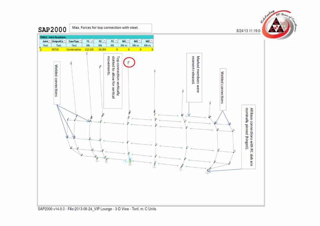
1.There were no design in the IFC drawings for this item.2. The VIP Lounge surface is part of conical shape (each curved column has different elliptic shape) and some of the curved columns are not reaching to the RC slab due to Architectural shape of the wall / RC slab limits.3. Area is very congested with MEP. Ducts at the top of the curved columns.4. The consultant added some requirements when we sent the first design with fixed top and bottom connections to reduce the forces acting on the main steel and the fourth floor RC slab.(their requirements was to make the top connection vertically slotted to allow for the vertical movement of the main steel & make the bottom connection pinned)By following the instructions of the consultant we suffered from very big reactions and the number of bolts and size of base plate increased severely. We introduced some releases to overcome this problem.5. The Secondary steel shouldn’t be visible from both sides of the curved wall so our system must fit inside the 210 mm wall cavity left by the Arch designer
VIP Lounge Curved wall supporting system.
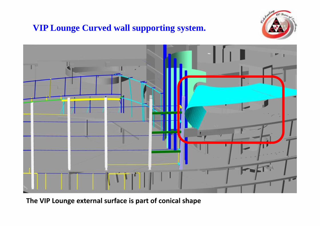
The VIP Lounge external surface is part of conical shape
VIP Lounge Curved wall supporting system.
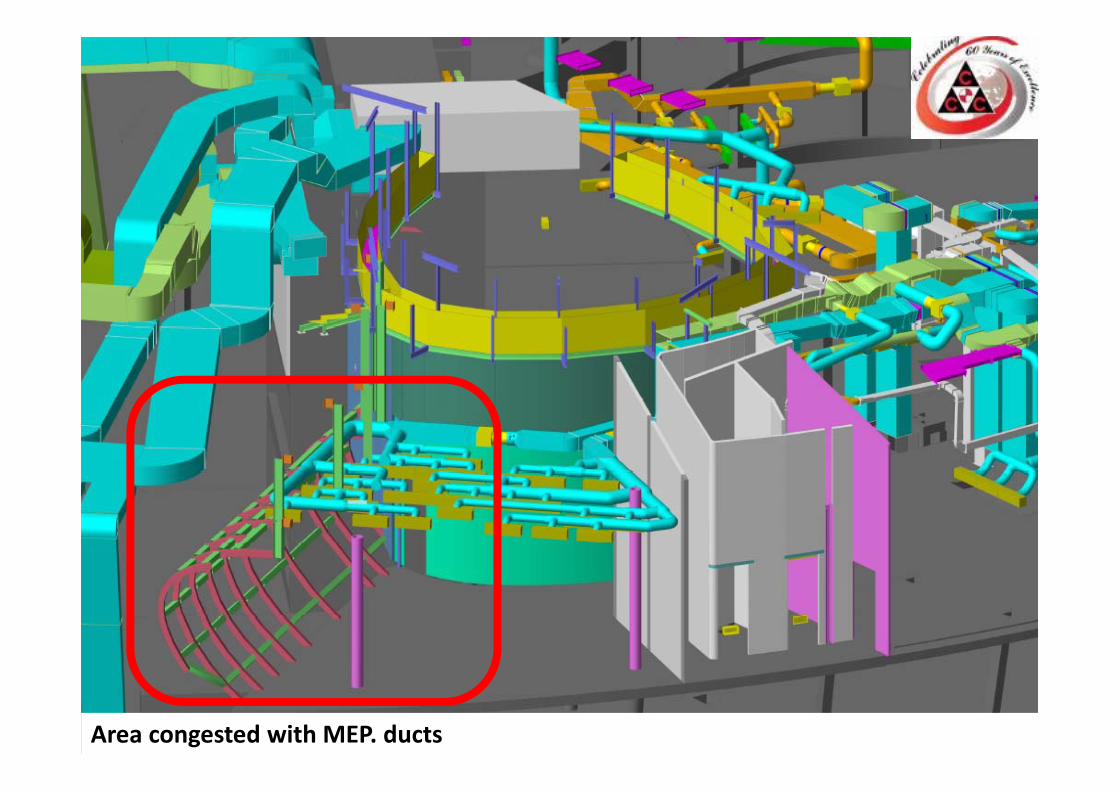
Area congested with MEP. ducts
VIP Lounge Curved wall supporting system.
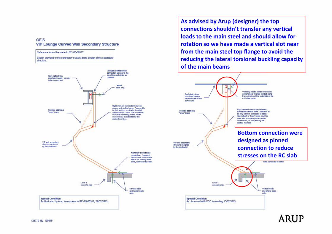
As advised by Arup (designer) the top connections shouldn’t transfer any vertical loads to the main steel and should allow for rotation so we have made a vertical slot near from the main steel top flange to avoid the reducing the lateral torsional buckling capacity of the main beams
Bottom connection were designed as pinned connection to reduce stresses on the RC slab
VIP Lounge Curved wall supporting system.

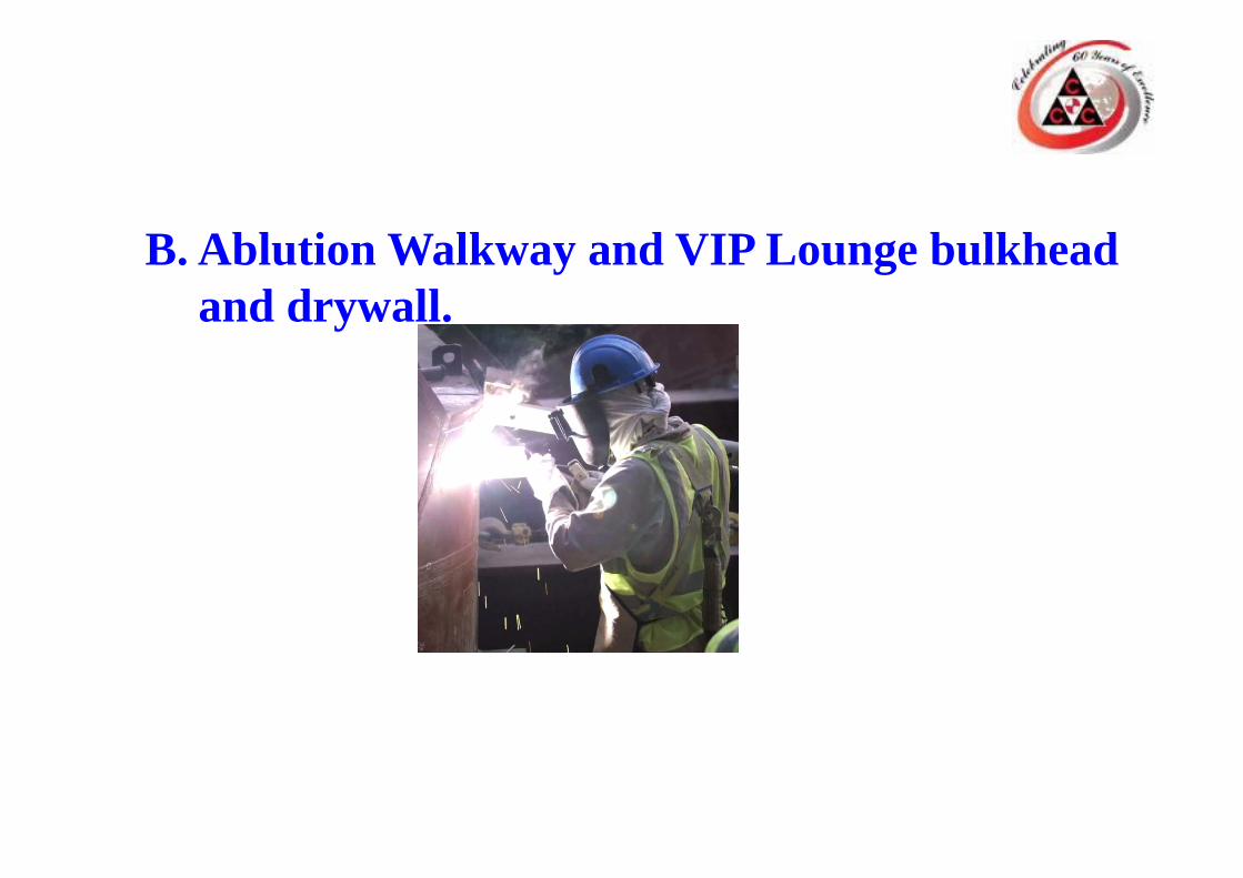
B. Ablution Walkway and VIP Lounge bulkhead and drywall.
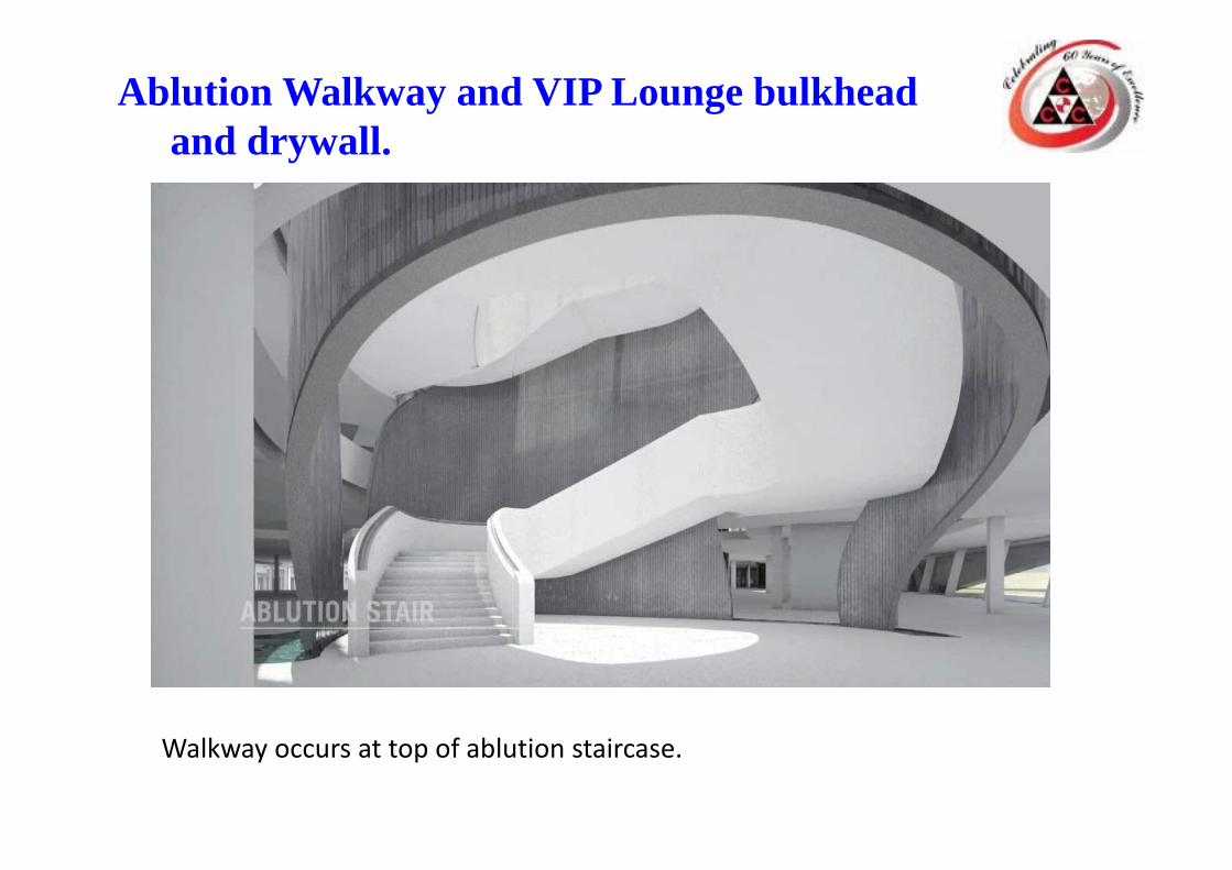
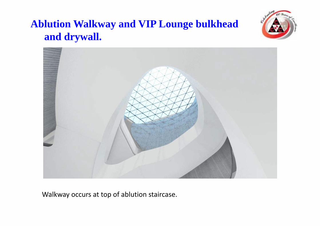
Ablution Walkway and VIP Lounge bulkhead and drywall.
Walkway occurs at top of ablution staircase.
Ablution Walkway and VIP Lounge bulkhead and drywall.
Walkway occurs at top of ablution staircase.
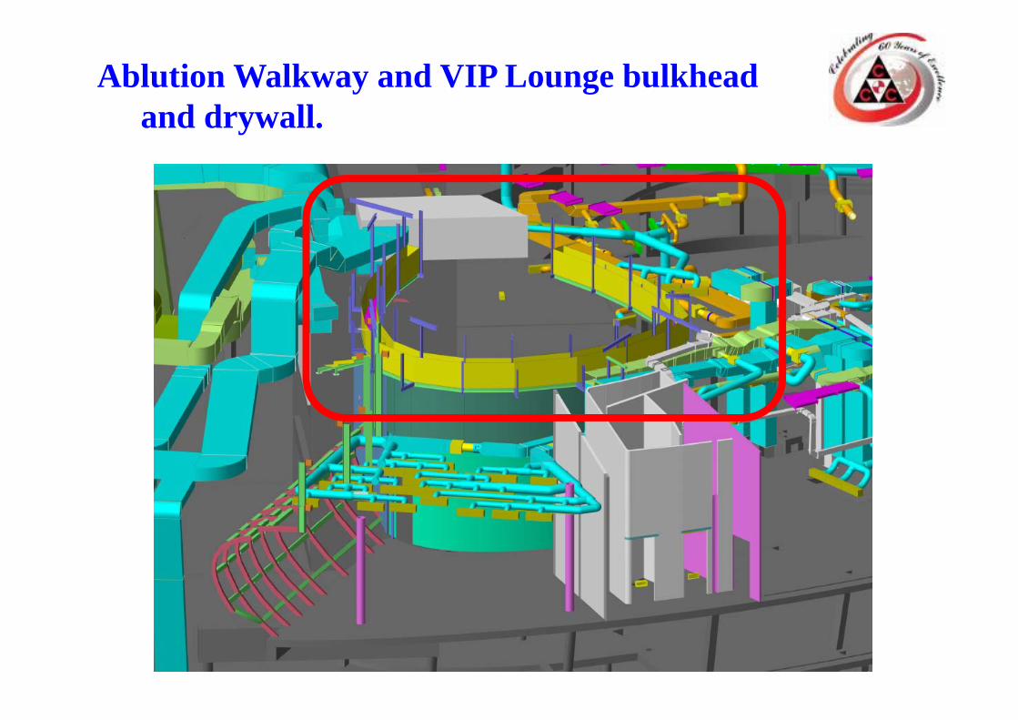
Ablution Walkway and VIP Lounge bulkhead and drywall.
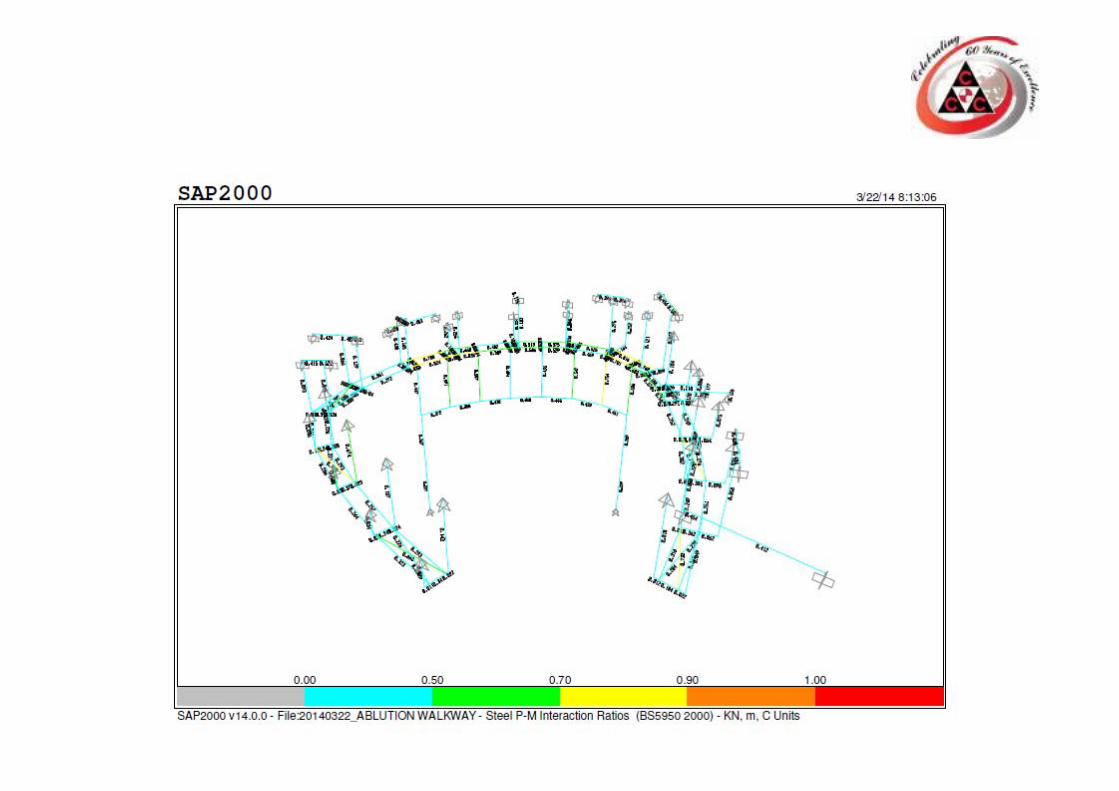
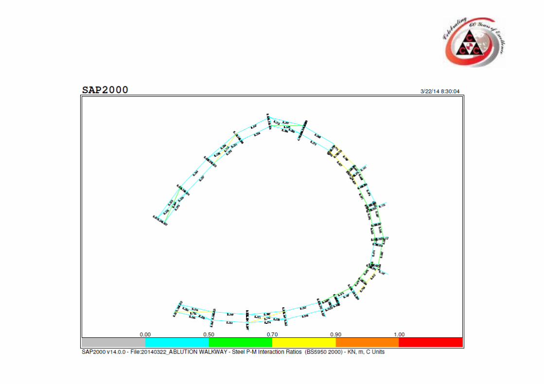
Ablution Walkway and VIP Lounge bulkhead and drywall.
1.There is no design in the IFC drawings for this item as this item added as change order recently and the client requested us to provide the structural/Architectural proposal and drawings.2. The Ablution walkway occurs above the mosque ablution staircase and its function is to carry out maintenance of ablution cascade wall water feeder “Gutter” so we have a very small distance nearly 600 mm between the Gutter and the MEP. Ducts to place our structure.3. Area is very congested with MEP. Ducts/sec steel.4. We have to support the bulkhead and the glass wall closing the VIP Lounge from the ablution staircase side (how to avoid transfer any movement from main steel to the glass wall).5.After we did the pre‐design and by site visit we discovered that the MEP.Ducts were not matching the BIM model 100% so we made As‐built report for the ducts to see the influence on our system.
Ablution walkway and VIP Lounge bulkhead and drywall.
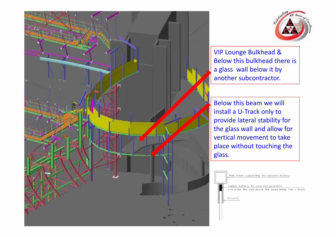
VIP Lounge Bulkhead & Below this bulkhead there is a glass wall below it by another subcontractor.
Below this beam we will install a U‐Track only to provide lateral stability for the glass wall and allow for vertical movement to take place without touching the glass.
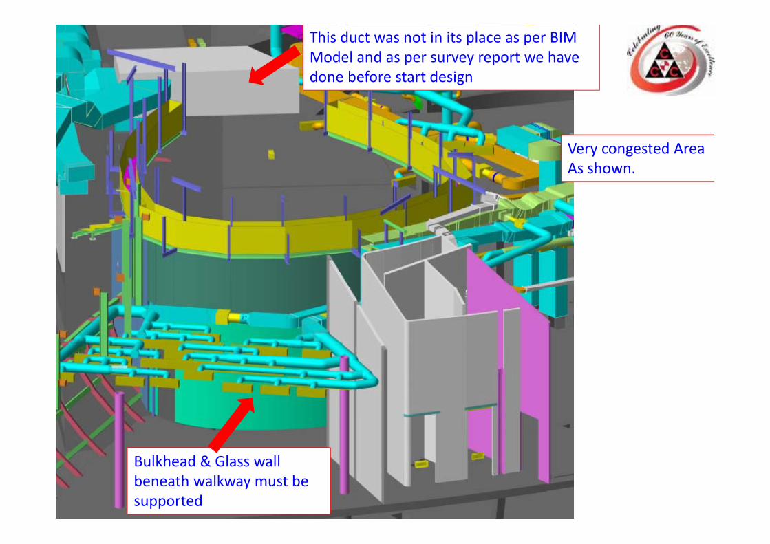
This duct was not in its place as per BIM Model and as per survey report we have done before start design
Bulkhead & Glass wall beneath walkway must be supported
Very congested AreaAs shown.
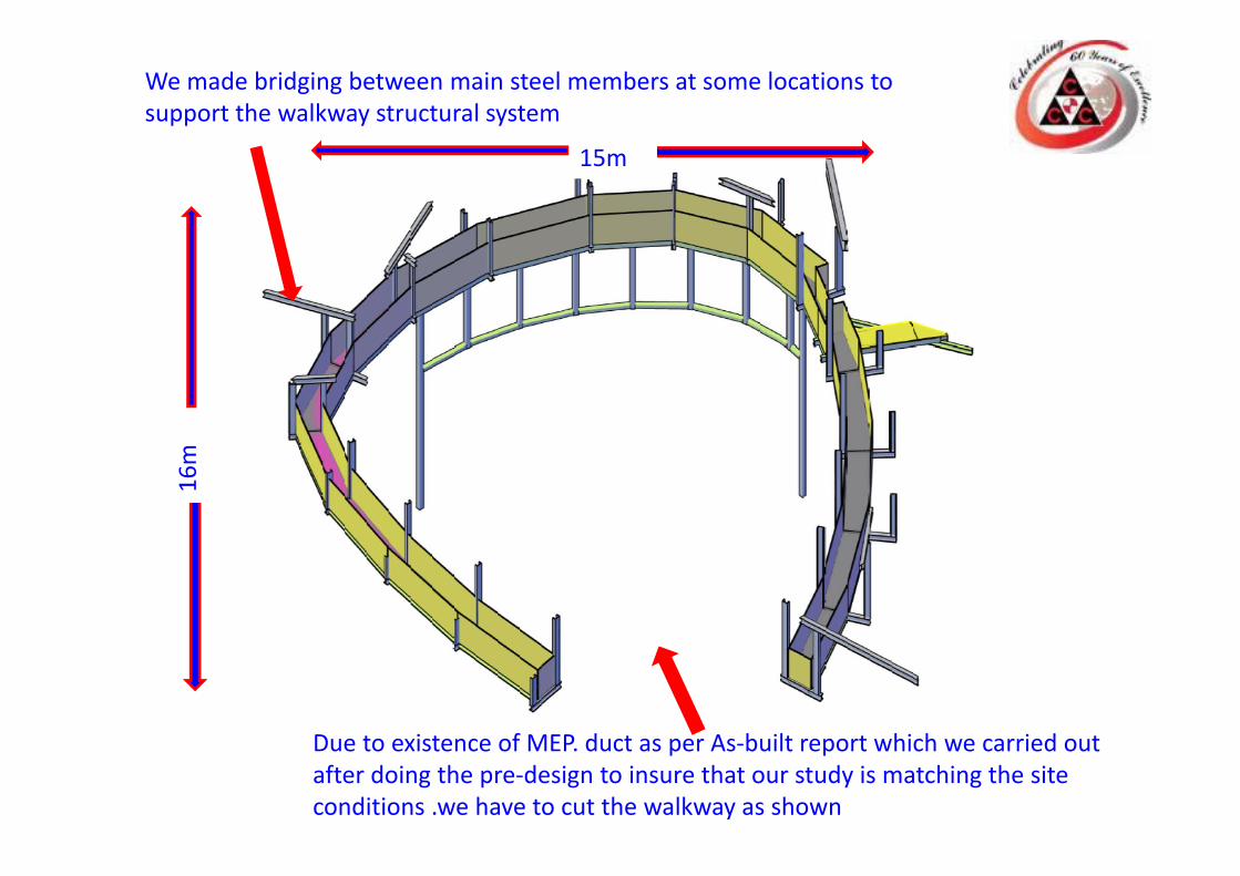
Due to existence of MEP. duct as per As‐built report which we carried out after doing the pre‐design to insure that our study is matching the site conditions .we have to cut the walkway as shown
We made bridging between main steel members at some locations to support the walkway structural system
15m16m
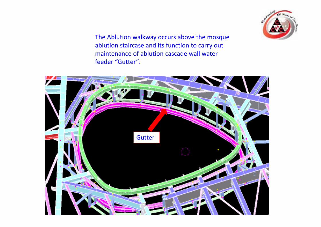
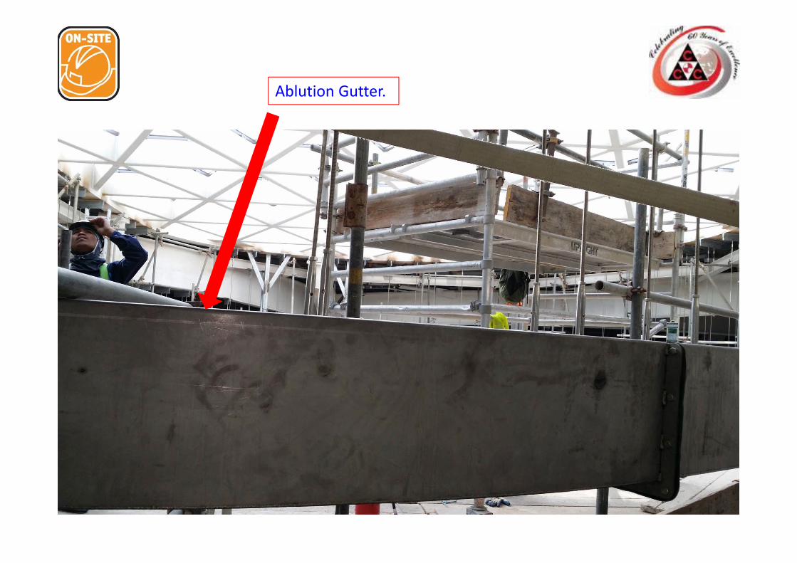
The Ablution walkway occurs above the mosque ablution staircase and its function to carry out maintenance of ablution cascade wall water feeder “Gutter”.
Gutter

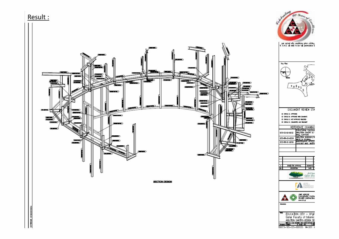
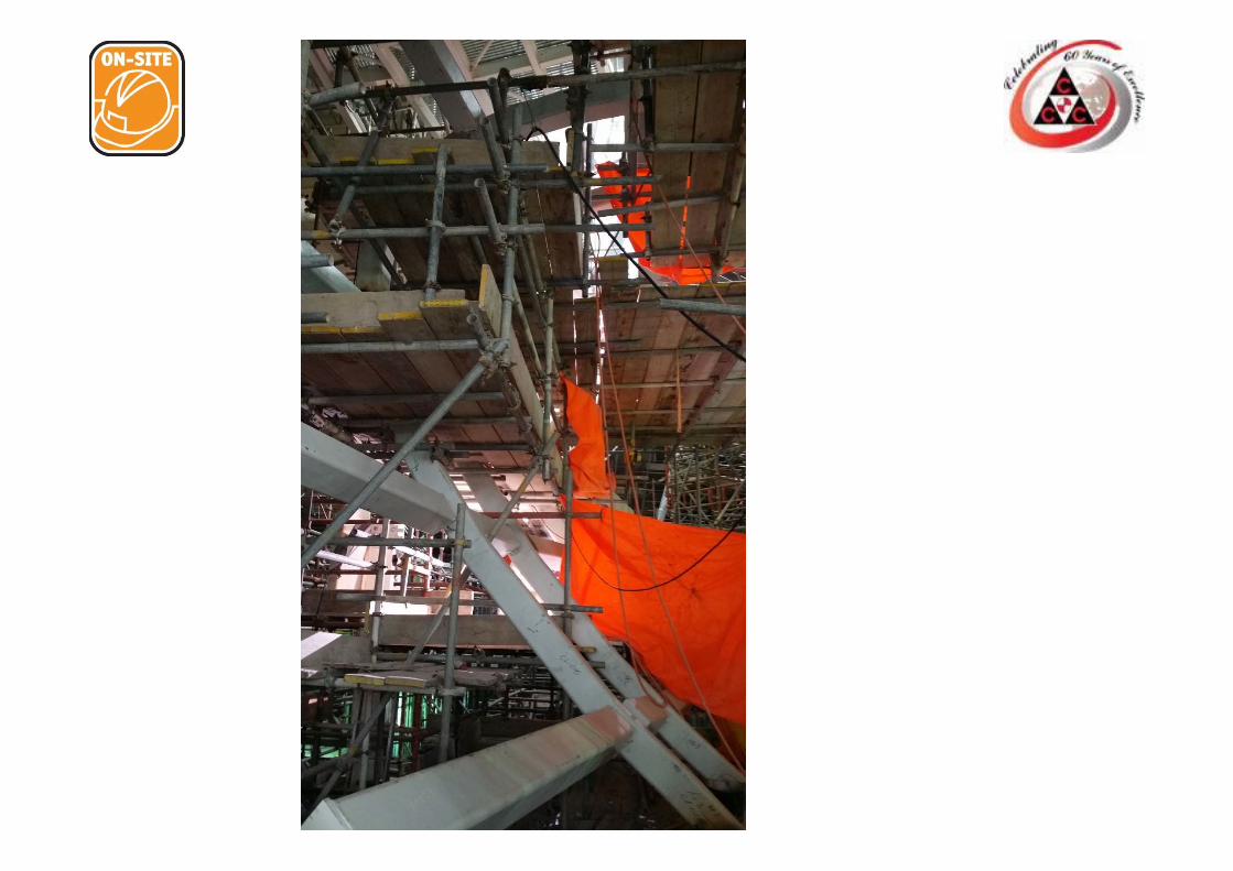
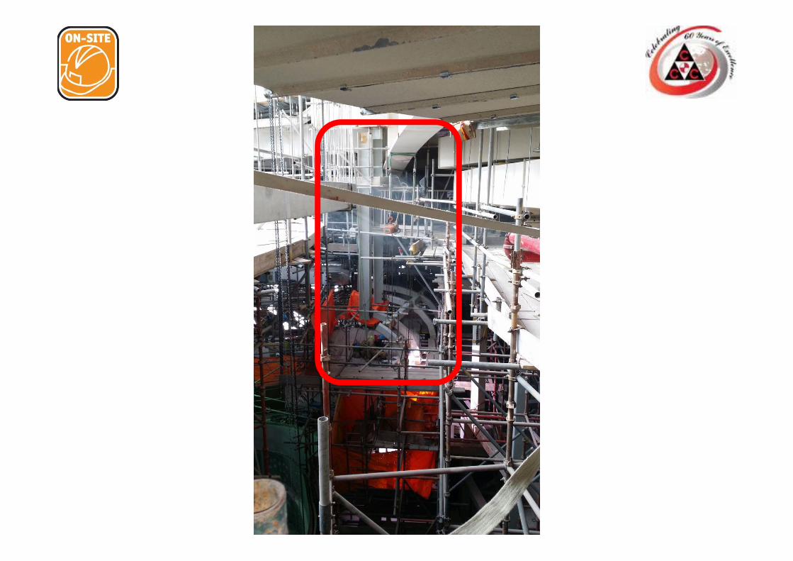
Result :
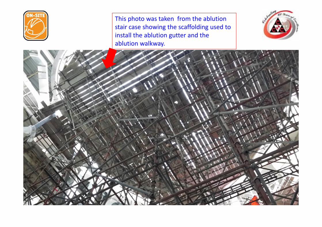
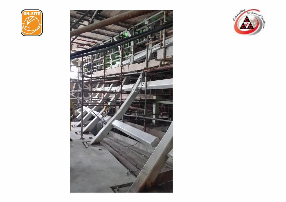
This photo was taken from the ablution stair case showing the scaffolding used to install the ablution gutter and the ablution walkway.
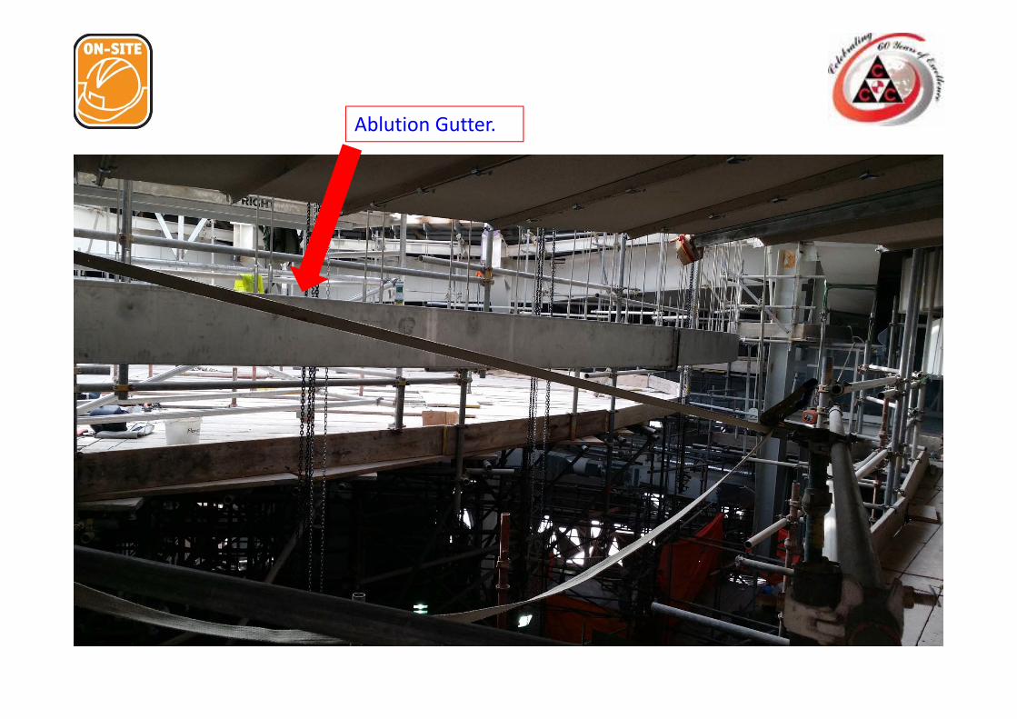
Ablution Gutter.
Ablution Gutter.
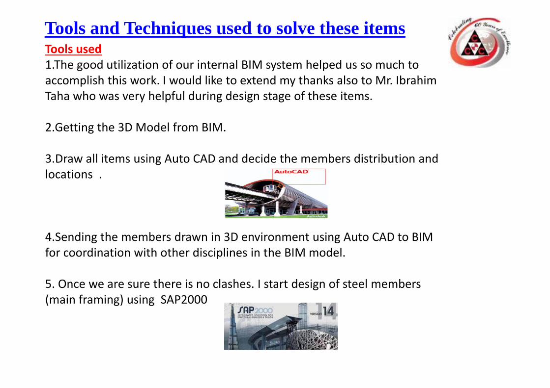
Tools used1.The good utilization of our internal BIM system helped us so much to accomplish this work. I would like to extend my thanks also to Mr. Ibrahim Taha who was very helpful during design stage of these items.
2.Getting the 3D Model from BIM.
3.Draw all items using Auto CAD and decide the members distribution and locations .
4.Sending the members drawn in 3D environment using Auto CAD to BIM for coordination with other disciplines in the BIM model.
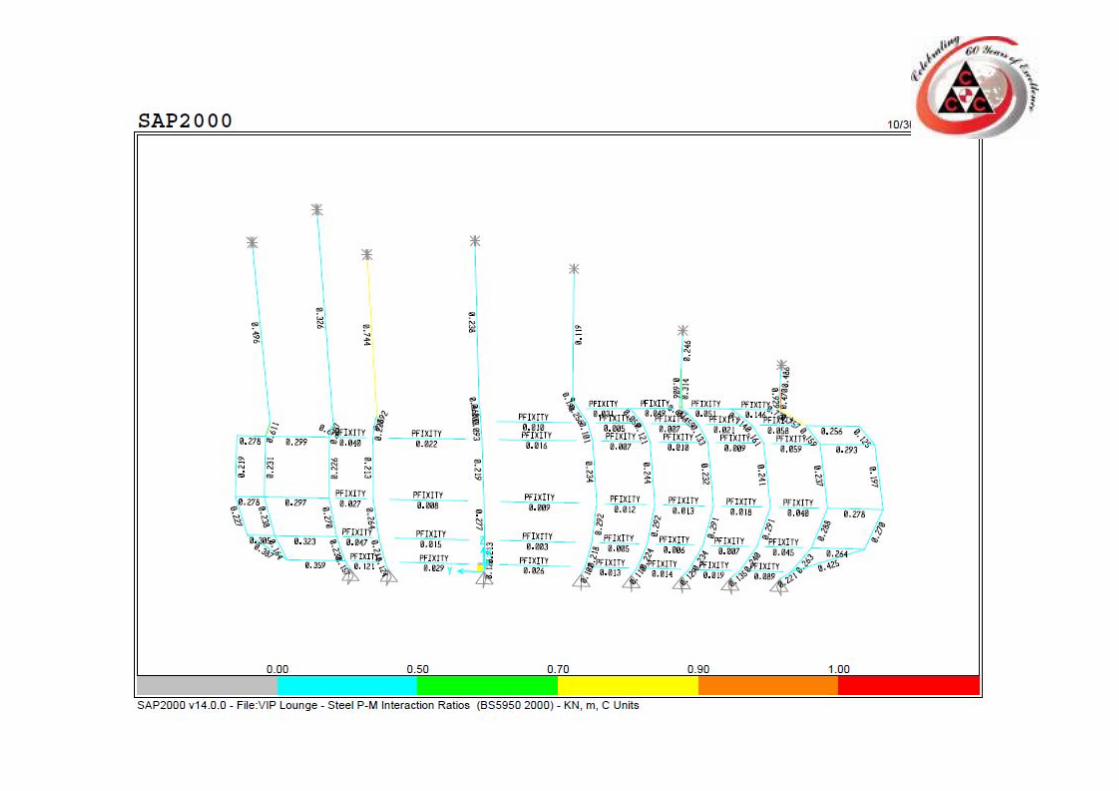
5. Once we are sure there is no clashes. I start design of steel members (main framing) using SAP2000
Tools and Techniques used to solve these items
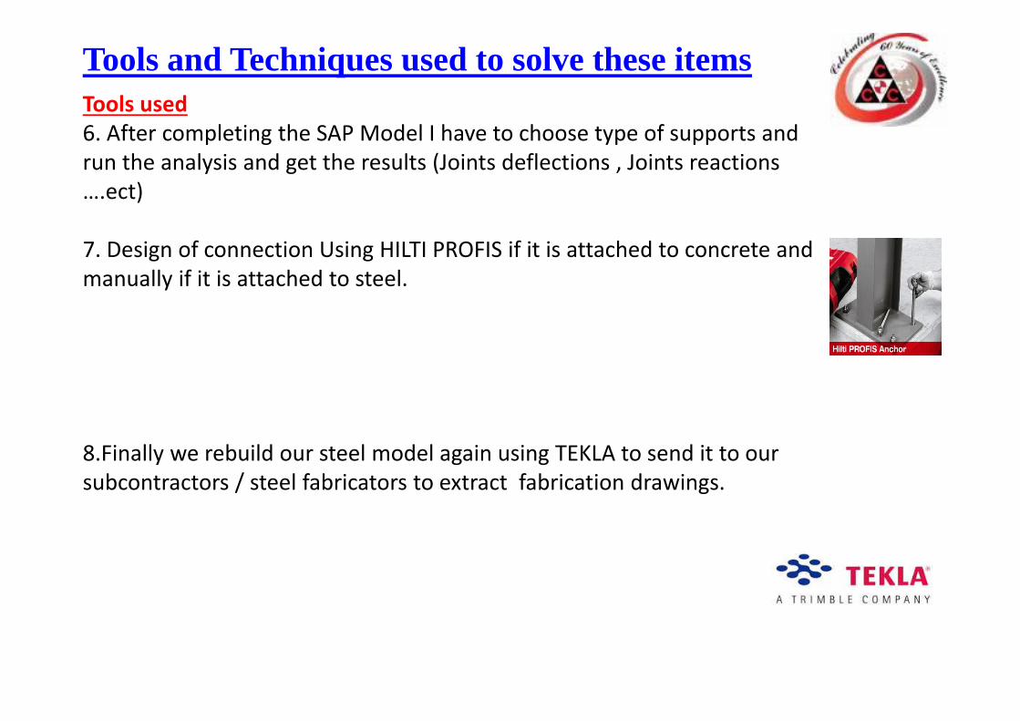
Tools used6. After completing the SAP Model I have to choose type of supports and run the analysis and get the results (Joints deflections , Joints reactions ….ect)
7. Design of connection Using HILTI PROFIS if it is attached to concrete and manually if it is attached to steel.
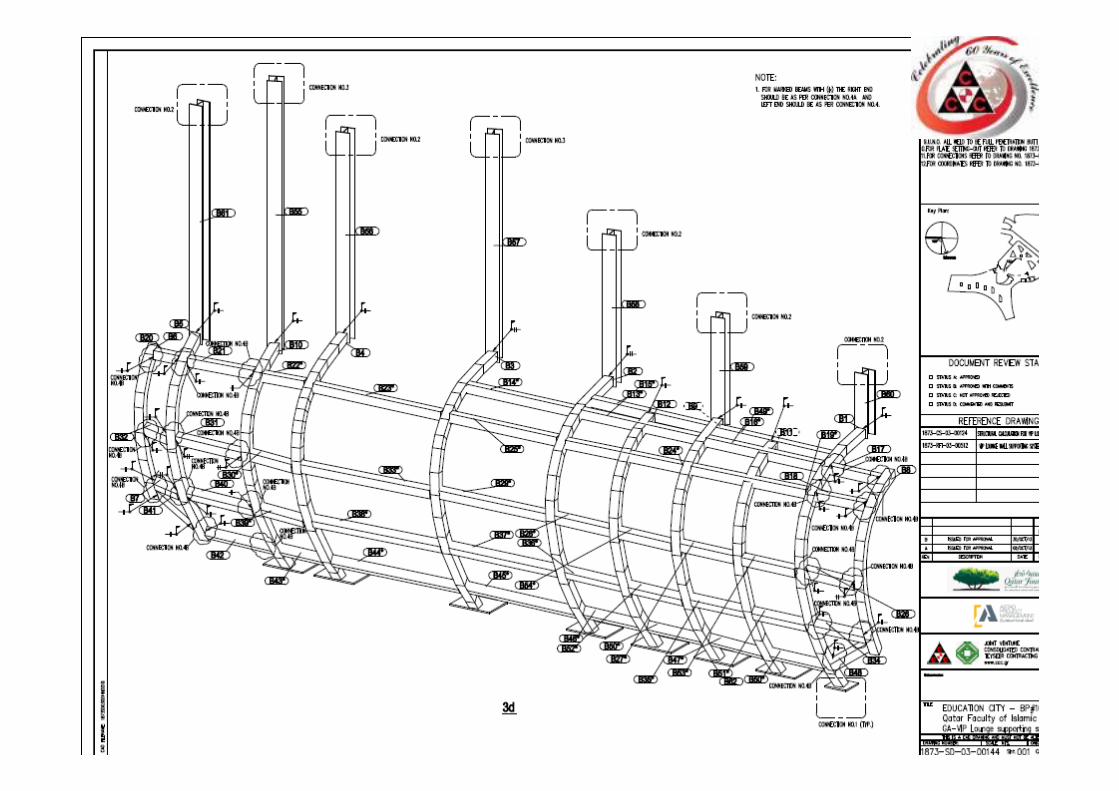
8.Finally we rebuild our steel model again using TEKLA to send it to our subcontractors / steel fabricators to extract fabrication drawings.
Tools and Techniques used to solve these items
Tools used9. Prepare the design drawings/GA/Assembly/ connection details and insure that we are placing coordinates of the members ends to avoid any wrong orientation on site later.
Tools and Techniques used to solve these items
Tools and Techniques used to solve these itemsTechniques1.First technique to be used “we can do it”Train your subconscious that you can do it & you can solve the problem.
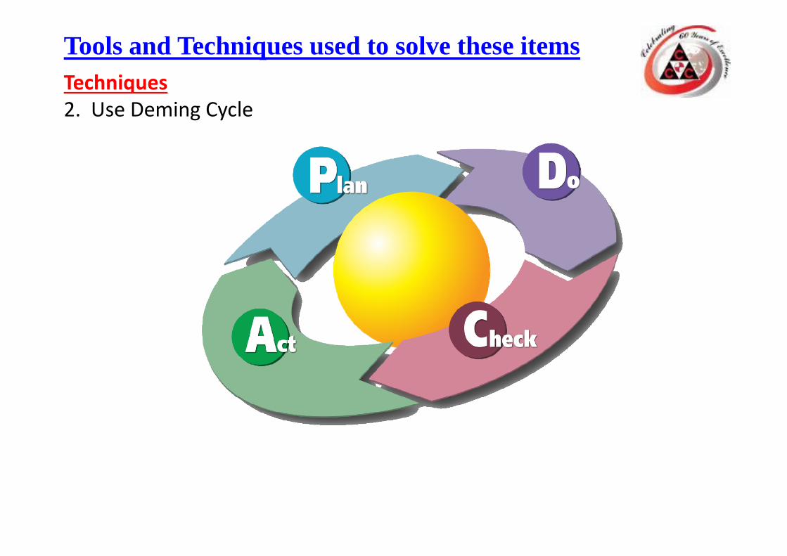
Tools and Techniques used to solve these itemsTechniques2. Use Deming Cycle
Tools and Techniques used to solve these itemsTechniques3. Using to do list technique in order to priorities your work and don’t not get lost.
Tools and Techniques used to solve these itemsTechniques
Last but not leastI would like to thank our project director Mr. Mahdi Salem for his support and trust.
Recommended