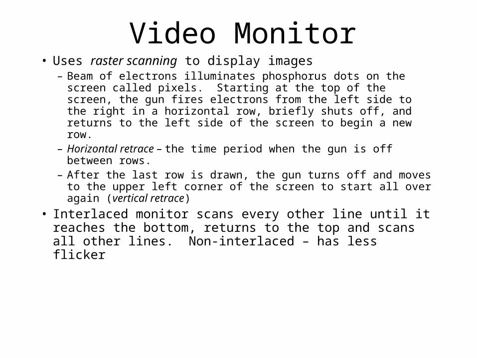
Video Monitor• Uses raster scanning to display images
– Beam of electrons illuminates phosphorus dots on the screen called pixels. Starting at the top of the screen, the gun fires electrons from the left side to the right in a horizontal row, briefly shuts off, and returns to the left side of the screen to begin a new row.
– Horizontal retrace – the time period when the gun is off between rows.
– After the last row is drawn, the gun turns off and moves to the upper left corner of the screen to start all over again (vertical retrace)
• Interlaced monitor scans every other line until it reaches the bottom, returns to the top and scans all other lines. Non-interlaced – has less flicker
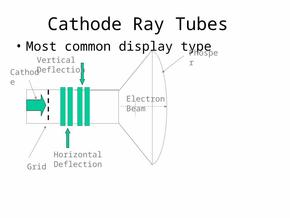
Cathode Ray Tubes• Most common display type
Vertical Deflection
Horizontal Deflection
Electron Beam
Phosper
Grid
Cathode
Raster Scan
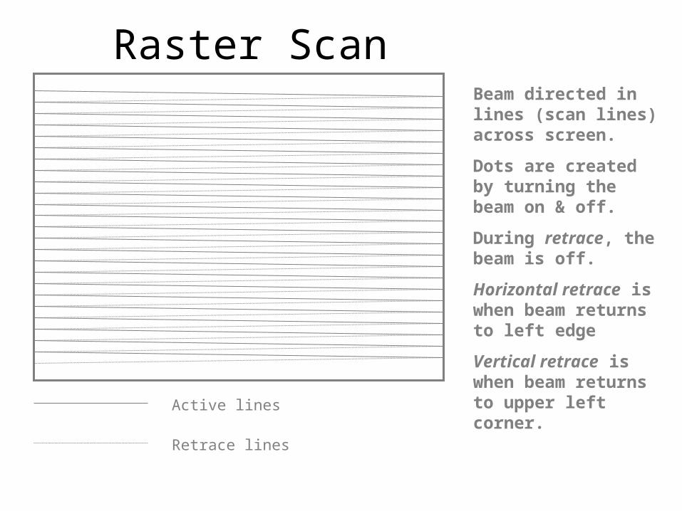
Active lines
Retrace lines
Beam directed in lines (scan lines) across screen.
Dots are created by turning the beam on & off.
During retrace, the beam is off.
Horizontal retrace is when beam returns to left edge
Vertical retrace is when beam returns to upper left corner.
• Raster line – horizontal line of video information that is displayed on screen
• 640x480 display has 480 raster lines, 640 pixels per line. Pixel is smallest subdivision on line.
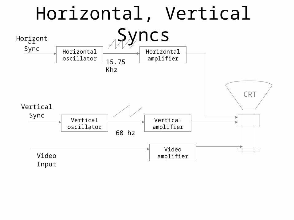
Horizontal, Vertical SyncsHorizontal oscillator
Horizontal amplifier
CRT
HorizontalSync
Vertical oscillator
Vertical amplifier
VerticalSync
Video amplifierVideoInput
60 hz
15.75 Khz
Video Monitor
• Clarity determined by several factors:– Dot pitch – distance between adjacent pixels
• .26 average – higher numbers >more distance
• Horizontal and vertical frequencies – the speed at which horizontal lines are drawn and the time it takes to draw all lines on the screen.
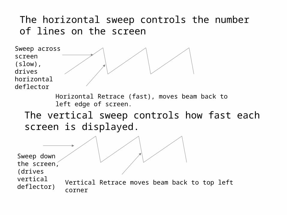
The horizontal sweep controls the number of lines on the screen
Sweep across screen (slow), drives horizontal deflector
Horizontal Retrace (fast), moves beam back to left edge of screen.
The vertical sweep controls how fast each screen is displayed.
Sweep down the screen, (drives vertical deflector)
Vertical Retrace moves beam back to top left corner

Color Monitors (cont)• Analog RGB Monitor
– Analog signals (0-0.7v)– Infinite number of colors available (generally, finite # are
generated – 256K, 16M, 24M)– Typically a DAC (digital-to-analog converter used) – 6-bit
DAC for each video signal to generate 64 different voltage levels between 0V and 0.7V (64 red, 64 green, 64 blue = 256k different colors available)
– 15-pin connector (red,green,blue, red gnd, green gnd, blue gnd, horizontal retrace, vertical retrace, pin 9 blocked,color detect, monochrome detect)
– Speed of DAC is critical – most displays require an operating conversion time of 25ns to 40ns max.
• 7-bit converters can display 2M colors (128x128x128)• 8-bit converters can display 16M colors (256x256x256)
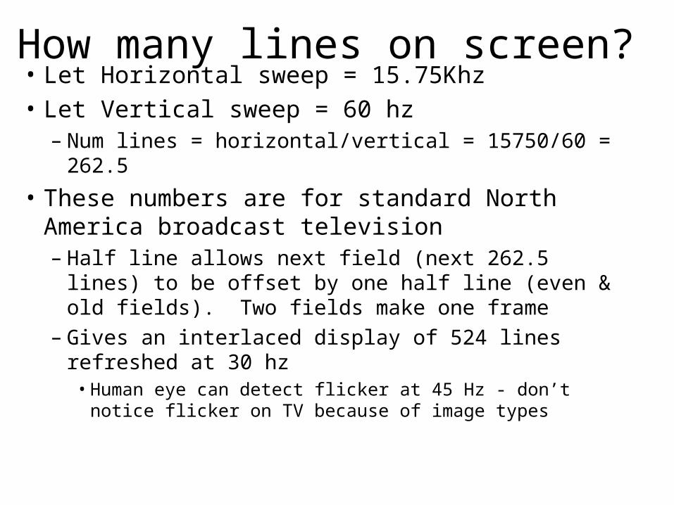
How many lines on screen?• Let Horizontal sweep = 15.75Khz
• Let Vertical sweep = 60 hz– Num lines = horizontal/vertical = 15750/60 = 262.5
• These numbers are for standard North America broadcast television– Half line allows next field (next 262.5 lines) to be offset
by one half line (even & old fields). Two fields make one frame
– Gives an interlaced display of 524 lines refreshed at 30 hz• Human eye can detect flicker at 45 Hz - don’t notice flicker on
TV because of image types
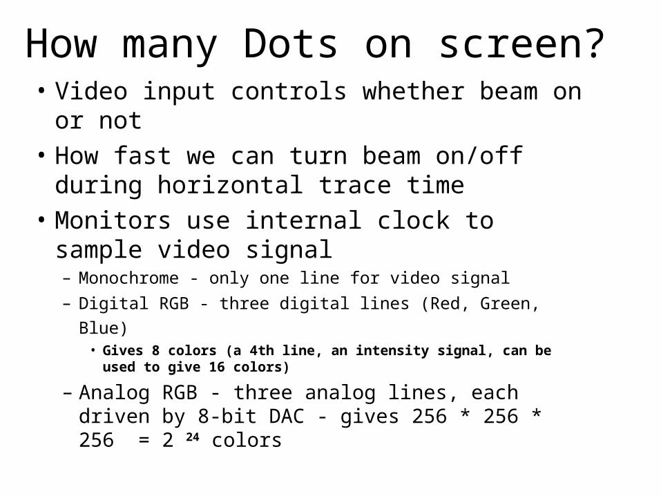
How many Dots on screen? • Video input controls whether beam on or not
• How fast we can turn beam on/off during horizontal trace time
• Monitors use internal clock to sample video signal– Monochrome - only one line for video signal
– Digital RGB - three digital lines (Red, Green, Blue) • Gives 8 colors (a 4th line, an intensity signal, can be used to give 16
colors)
– Analog RGB - three analog lines, each driven by 8-bit DAC - gives 256 * 256 * 256 = 2 24 colors
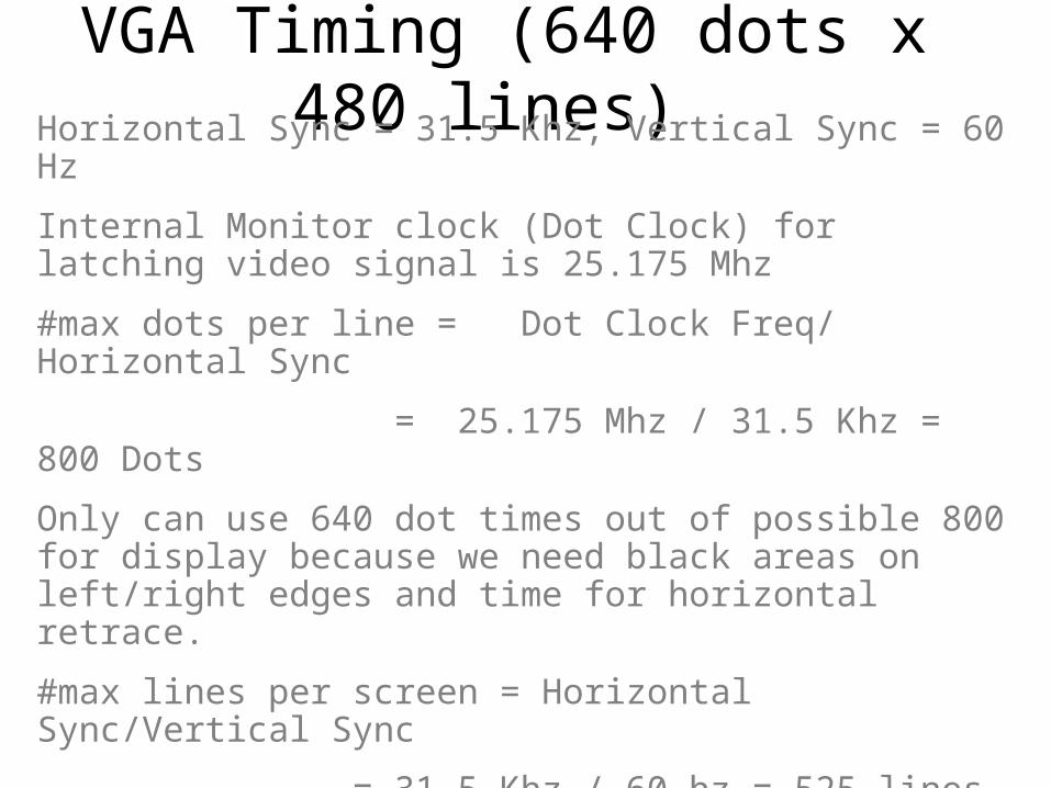
VGA Timing (640 dots x 480 lines) Horizontal Sync = 31.5 Khz, Vertical Sync = 60 Hz
Internal Monitor clock (Dot Clock) for latching video signal is 25.175 Mhz
#max dots per line = Dot Clock Freq/ Horizontal Sync
= 25.175 Mhz / 31.5 Khz = 800 Dots
Only can use 640 dot times out of possible 800 for display because we need black areas on left/right edges and time for horizontal retrace.
#max lines per screen = Horizontal Sync/Vertical Sync
= 31.5 Khz / 60 hz = 525 lines
Only 480 lines usable, need blank areas on top/bottom, time for vertical retrace
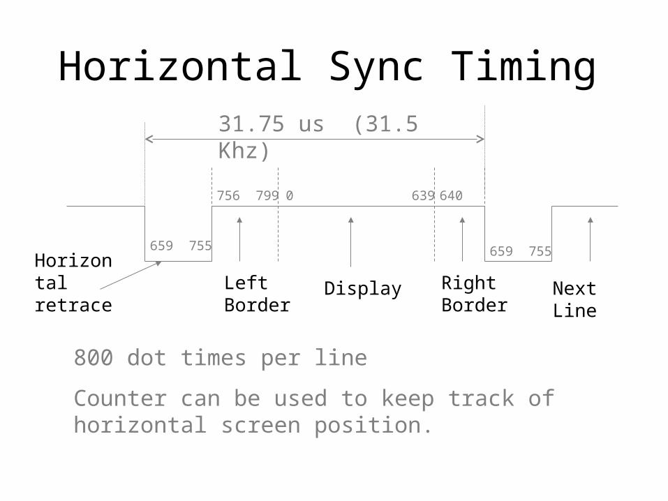
Horizontal Sync Timing
659 755
756 799 0 639 640
659 755
31.75 us (31.5 Khz)
Horizontal retrace Left
BorderDisplay Right
BorderNext Line
800 dot times per line
Counter can be used to keep track of horizontal screen position.
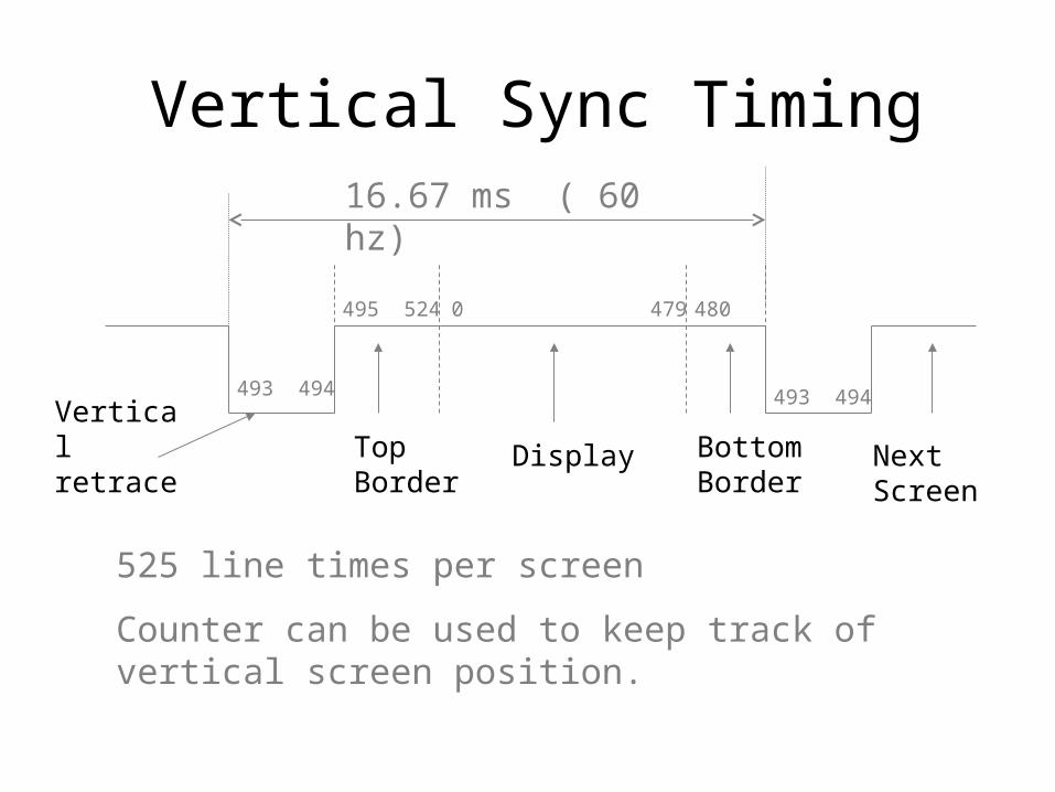
Vertical Sync Timing
493 494
495 524 0 479 480
493 494
16.67 ms ( 60 hz)
Vertical retrace Top
BorderDisplay Bottom
BorderNext Screen
525 line times per screen
Counter can be used to keep track of vertical screen position.
Video Resolution• Set by software• Limited by the capacity of the video graphics
adapter and the amount of video memory. • Expressed as the number of horizontal pixels,
followed by the number of vertical pixels.– 640 x 480 (standard VGA)– 800 x 600 (super VGA)– 1024 x 768 (extended VGA)– 1152 x 864– 1280 x 1024
• # of simultaneous colors supported is between 256(28 ) and 16 million (224)
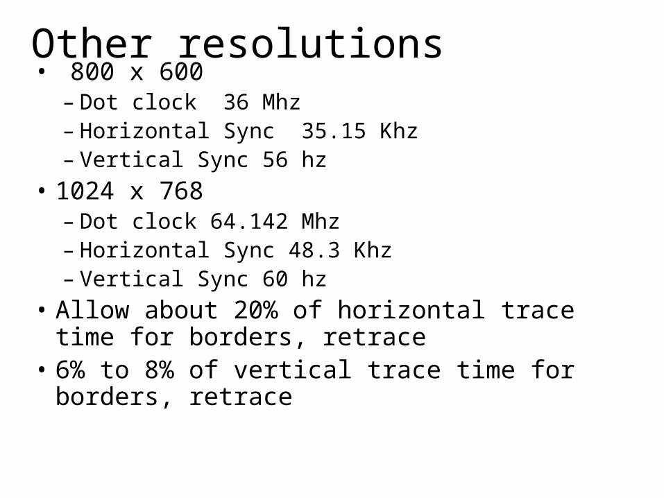
Other resolutions• 800 x 600
– Dot clock 36 Mhz– Horizontal Sync 35.15 Khz– Vertical Sync 56 hz
• 1024 x 768– Dot clock 64.142 Mhz– Horizontal Sync 48.3 Khz– Vertical Sync 60 hz
• Allow about 20% of horizontal trace time for borders, retrace
• 6% to 8% of vertical trace time for borders, retrace
Video Resolution
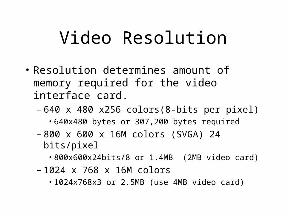
• Resolution determines amount of memory required for the video interface card.– 640 x 480 x256 colors(8-bits per pixel)
• 640x480 bytes or 307,200 bytes required
– 800 x 600 x 16M colors (SVGA) 24 bits/pixel• 800x600x24bits/8 or 1.4MB (2MB video card)
– 1024 x 768 x 16M colors • 1024x768x3 or 2.5MB (use 4MB video card)
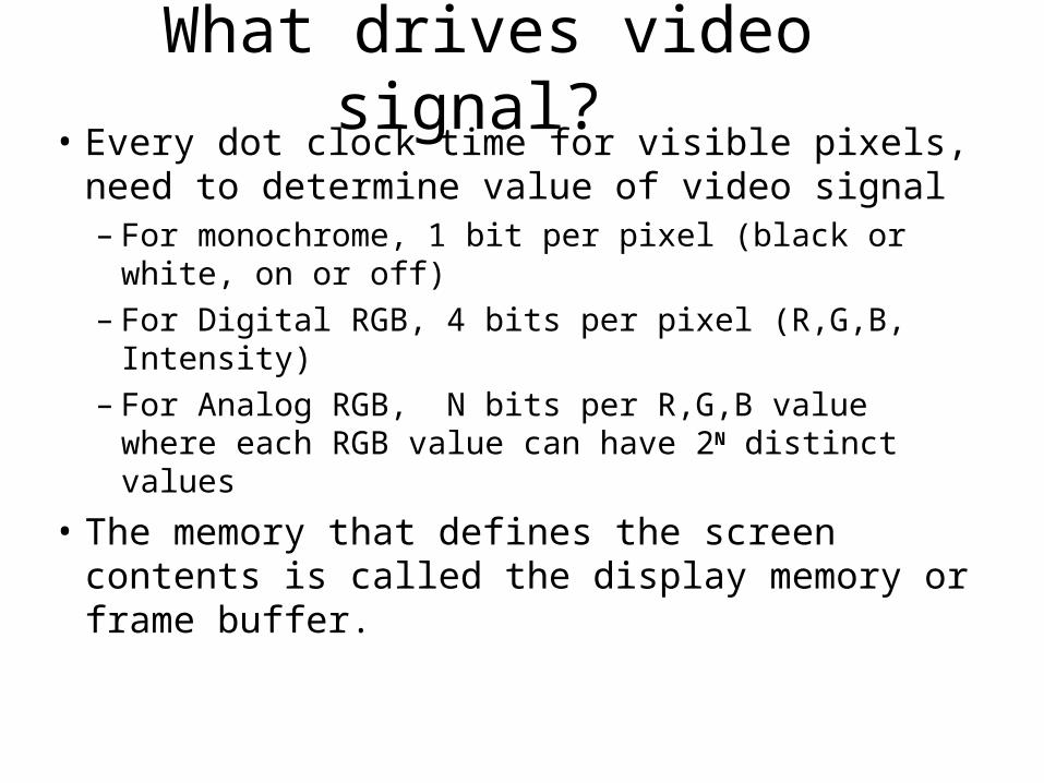
What drives video signal? • Every dot clock time for visible pixels, need to
determine value of video signal– For monochrome, 1 bit per pixel (black or white, on
or off)– For Digital RGB, 4 bits per pixel (R,G,B, Intensity)– For Analog RGB, N bits per R,G,B value where
each RGB value can have 2N distinct values
• The memory that defines the screen contents is called the display memory or frame buffer.
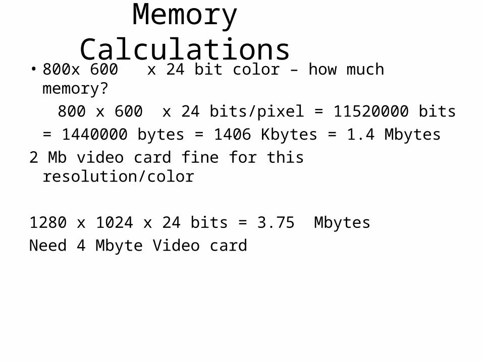
Memory Calculations• 800x 600 x 24 bit color – how much memory?
800 x 600 x 24 bits/pixel = 11520000 bits
= 1440000 bytes = 1406 Kbytes = 1.4 Mbytes
2 Mb video card fine for this resolution/color
1280 x 1024 x 24 bits = 3.75 Mbytes
Need 4 Mbyte Video card
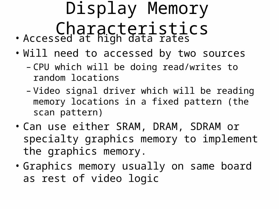
Display Memory Characteristics • Accessed at high data rates
• Will need to accessed by two sources– CPU which will be doing read/writes to random locations– Video signal driver which will be reading memory
locations in a fixed pattern (the scan pattern)
• Can use either SRAM, DRAM, SDRAM or specialty graphics memory to implement the graphics memory.
• Graphics memory usually on same board as rest of video logic

Memory Access
Video Memory
Video Controller
Read Only,
Sequential Access
CPU
Write Mostly,
Random Access
Video Card
CRT
Video controller must arbitrate between its accesses and CPU accesses. CPU connection to card can either be via system bus (I.e. PCI bus) or dedicated connection (Advanced Graphics Port).

Video Memory• The PC has a memory-mapped video display.
Each screen position occupies a separate memory address. The video memory is special high speed VRAM (video RAM).
• In color text mode, VRAM is at B8000• In color graphics mode, VRAM is at A0000.• DOS applications typically write text and graphics
directly to video display buffer – much faster than using built-in DOS subroutines.
• Windows applications do not use direct video memory access because it corrupts the built-in redrawing of the screen by Windows directly.
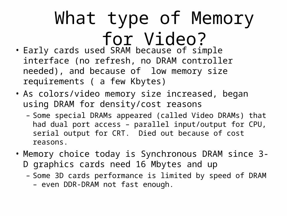
What type of Memory for Video?• Early cards used SRAM because of simple interface (no
refresh, no DRAM controller needed), and because of low memory size requirements ( a few Kbytes)
• As colors/video memory size increased, began using DRAM for density/cost reasons– Some special DRAMs appeared (called Video DRAMs) that had
dual port access – parallel input/output for CPU, serial output for CRT. Died out because of cost reasons.
• Memory choice today is Synchronous DRAM since 3-D graphics cards need 16 Mbytes and up – Some 3D cards performance is limited by speed of DRAM – even
DDR-DRAM not fast enough.
Video RAM
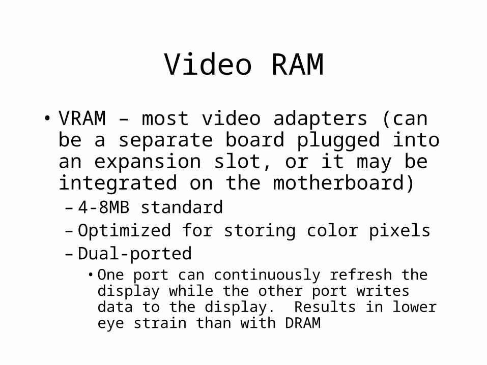
• VRAM – most video adapters (can be a separate board plugged into an expansion slot, or it may be integrated on the motherboard)– 4-8MB standard– Optimized for storing color pixels– Dual-ported
• One port can continuously refresh the display while the other port writes data to the display. Results in lower eye strain than with DRAM
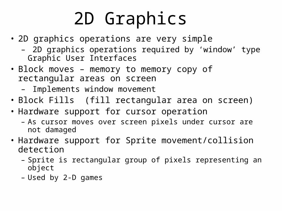
2D Graphics• 2D graphics operations are very simple
– 2D graphics operations required by ‘window’ type Graphic User Interfaces
• Block moves – memory to memory copy of rectangular areas on screen– Implements window movement
• Block Fills (fill rectangular area on screen)• Hardware support for cursor operation
– As cursor moves over screen pixels under cursor are not damaged
• Hardware support for Sprite movement/collision detection– Sprite is rectangular group of pixels representing an object– Used by 2-D games

Animation• To produce animation on a screen, successive
‘frames’ are displayed in which screen objects are in slightly different positions in each frame.
• The area of memory that the video controller is currently displaying on screen is the active Frame Buffer. – Most cards support two frame buffers. The CPU
writes to the 2nd frame buffer to prepare the next frame.
– When the next frame is ready, the 2nd frame buffer becomes the active Frame buffer and the 1st frame buffer is used to create the next frame.
• The rate at which new frames are produced is called the Frame Rate (not the same as Video refresh rate).
Windows RAM
• Optimized for video graphics displays.
• Generally outperforms VRAM, allowing screen to be refreshed more quickly.
Synchronous Graphics RAM
• Single ported RAM used on video accelerator cards.
• Two video memory pages can be opened at the same time.
• Able to clear memory quickly
• Well-suited to 3-D applications
Video Palettes
• Video generation circuit is used to generate VGA video. Each color is generated with an 18-bit digital code (6 bits red, 6 bits green,6 bits blue)
• 18 bit code is applied to the DAC. The address input selects one of the 256 colors stored as 18-bit binary codes. Thus 256 colors out of a possible 256K colors are allowed to be displayed at one time.
• 18-bit code stored in video display RAM VRAM is used to specify a color
Recommended