7/27/2019 Vent and Flare Systems
http://slidepdf.com/reader/full/vent-and-flare-systems 1/1
enggcyclopedia.com http://www.enggcyclopedia.com/vent-flare-systems/
Vent and Flare Systems
Buoyancy seals and velocity seals- Buoyancy seal typically uses the diff erence
in densities o f the purge gas and ambient air to keep the air f rom entering f lare
system. Velocity seal is a cone-shaped obst ruction placed inside the f lare tip soas to o bstruct the inf iltrating air f rom ‘hugging the inner wall’. The purge gas f low
coming through the cone is a f ocused stream which sweeps away the inf iltrating
air along with it .
Continuous purge gas flow requirement in flare networks – One of the ways
to avoid air ingress into t he f lare stack, vent KO drum, f lare network and
subsequent catast rophic consequences, is to cont inuously purge a small f low
rate of hydrocarbon gases. This continuous hydrocarbon gas purge f low in the f lare network helps to build
up some positive backpressure at the vent knock out drum.
Emissivity coefficient for flare tip – Emissivity coef f icient f or a f lare tip is the fraction of heat generatedat the f lare tip that is radiated to surroundings. Not all the heat that is generated by burning hydrocarbon
gases at the tip of a f lare is radiated. Major f raction of the heat generated by a f lare is carried to the
surroundings in the f orm of hot gases by convection and the f raction of this heat is simply radiated to
surroundings.
Flar e radiation plots / isopleths – Radiation plot s are representat ive of the incident radiated heat f rom
f lare reaching at dif f erent locations in the surroundings. Radiation plots typically consist of isopleths.
Isopleths are curves o n a map of the f lare surroundings which connect geographical points receiving the
same intensity of heat radiated f rom the f lare.
Flar e tip burn back – Burn back of the f lare tip is caused by low exit velocities o f the gas at f lare tip. The
f lare tip and f lare stack diameter are designed handling f or the maximum possible f low in the f lare network.
However, the normal gas f low in the f lare stack is much lower than the design f low rate, resulting in low exit
gas velocities at the f lare tip. Low gas velocities mean that the gas begins to burn much closer to t he f lare
tip than desired, thus causing burn back of the f lar e tip.
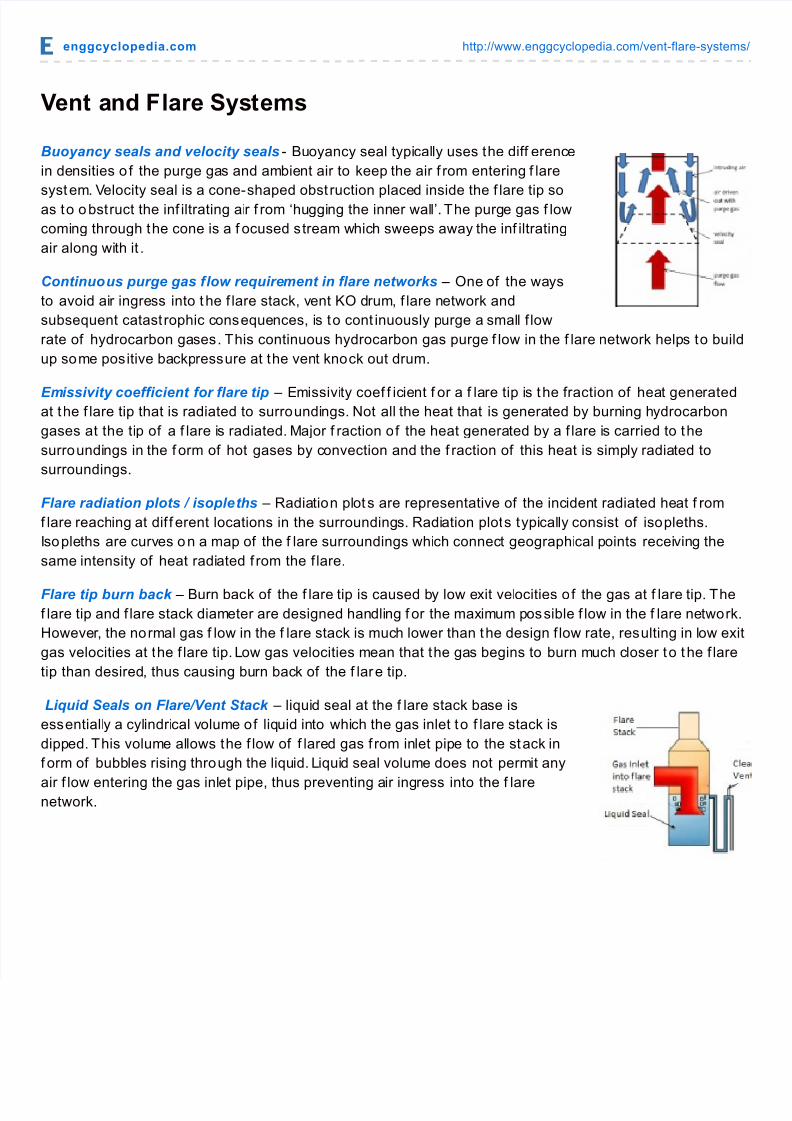
Liquid Seals on Flare/Vent Stack – liquid seal at the f lare stack base is
essentially a cylindrical volume of liquid into which the gas inlet to f lare stack is
dipped. This volume allows the f low of f lared gas f rom inlet pipe to the stack in
f orm of bubbles rising through the liquid. Liquid seal volume does not permit any
air f low entering the gas inlet pipe, thus preventing air ingress into the f larenetwork.
Recommended