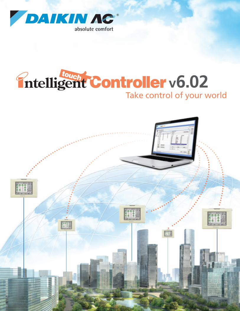
Take control of your worldv6.02
Intelligent Touch Controller
Centralized and advanCed vrv Control
tenant Billing
anCillary equipment Control
WeB aCCess and alert e-mail
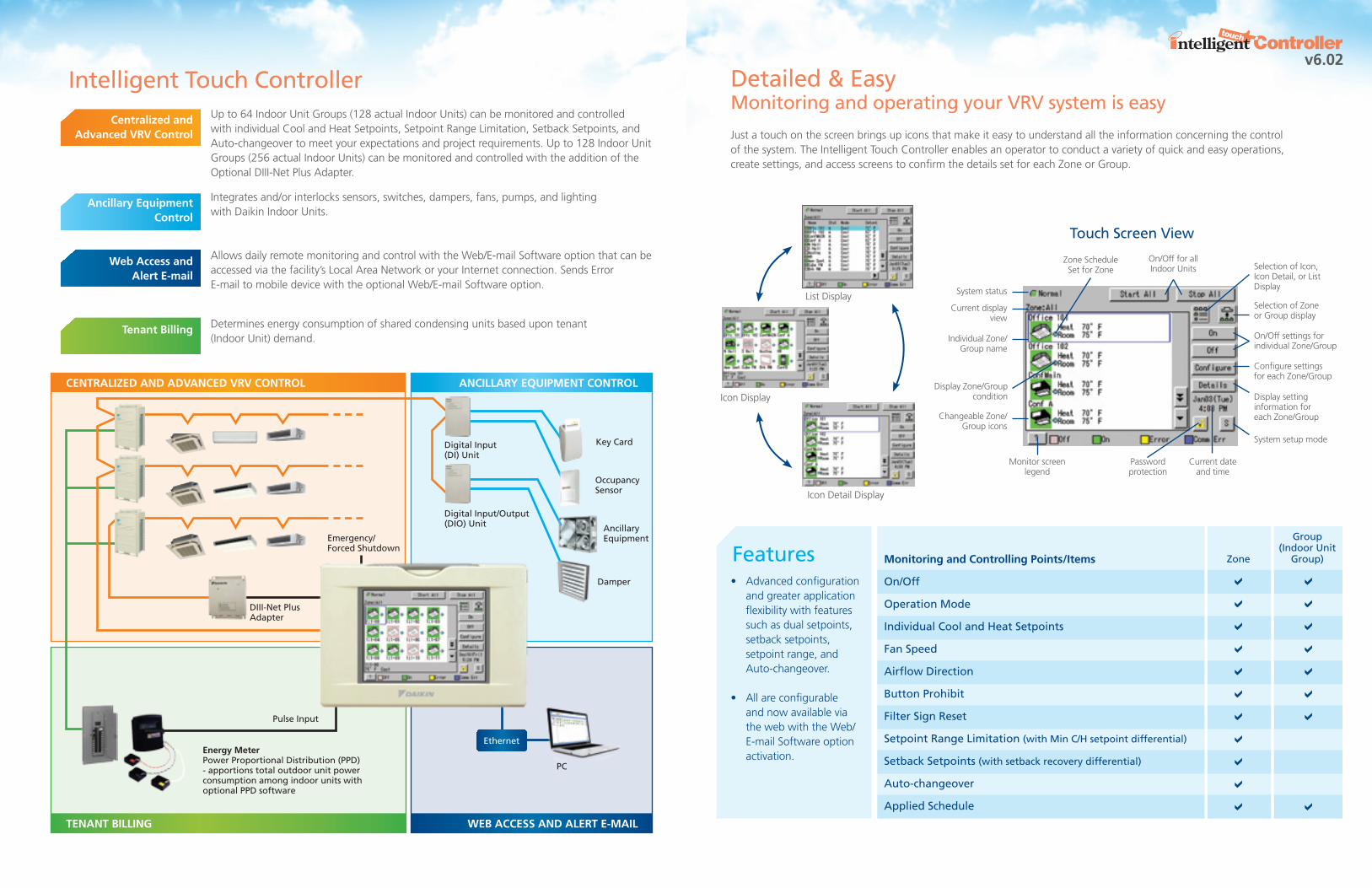
Up to 64 Indoor Unit Groups (128 actual Indoor Units) can be monitored and controlled with individual Cool and Heat Setpoints, Setpoint Range Limitation, Setback Setpoints, and Auto-changeover to meet your expectations and project requirements. Up to 128 Indoor Unit Groups (256 actual Indoor Units) can be monitored and controlled with the addition of the Optional DIII-Net Plus Adapter.
Integrates and/or interlocks sensors, switches, dampers, fans, pumps, and lighting with Daikin Indoor Units.
Allows daily remote monitoring and control with the Web/E-mail Software option that can be accessed via the facility’s Local Area Network or your Internet connection. Sends Error E-mail to mobile device with the optional Web/E-mail Software option.
Determines energy consumption of shared condensing units based upon tenant (Indoor Unit) demand.
Emergency/ Forced Shutdown
Pulse Input
DIII-Net Plus Adapter
PC
Digital Input (DI) Unit
Digital Input/Output(DIO) Unit
Key Card
OccupancySensor
Ancillary Equipment
Damper
energy meterPower Proportional Distribution (PPD) - apportions total outdoor unit power consumption among indoor units with optional PPD software
Centralized and advanced vrv Control
ancillary equipment Control
Web access and alert e-mail
tenant Billing
Detailed & Easy Monitoring and operating your VRV system is easy
Just a touch on the screen brings up icons that make it easy to understand all the information concerning the control of the system. The Intelligent Touch Controller enables an operator to conduct a variety of quick and easy operations, create settings, and access screens to confirm the details set for each Zone or Group.
monitoring and Controlling points/items
On/Off
Operation Mode
Individual Cool and Heat Setpoints
Fan Speed
Airflow Direction
Button Prohibit
Filter Sign Reset
Setpoint Range Limitation (with Min C/H setpoint differential)
Setback Setpoints (with setback recovery differential)
Auto-changeover
Applied Schedule
Zone
Group(Indoor Unit
Group)
• Advancedconfigurationand greater application flexibility with features such as dual setpoints, setback setpoints, setpoint range, and Auto-changeover.
• Allareconfigurableand now available via the web with the Web/ E-mail Software option activation.
Features
List Display
Icon Display
Icon Detail Display
Touch Screen View
Password protection
Monitor screen legend
Display Zone/Groupcondition
Zone ScheduleSet for Zone
Selection of Zone or Group display
System status
Current display view
Individual Zone/Group name
Changeable Zone/Group icons
Selection of Icon, Icon Detail, or List Display
On/Off settings for individual Zone/Group
Configure settings for each Zone/Group
Display settinginformation for each Zone/Group
System setup mode
Current date and time
On/Off for all Indoor Units
v6.02
Ethernet
Cooling on
Heating on
setback setpoint80˚F
setback setpoint 60˚F
space temp.
space temp.
6 a.m.
6 a.m.
5 p.m.
5 p.m.
unit on
unit on
unit off
unit off
Cooling setpointrange limit
Heating setpointrange limit
74˚F
72˚F
setpoint 72˚F
setpoint 70˚F
70˚F
68˚F
Cooling on
Heating on
occupied
occupied
unoccupied
unoccupied
setback period
setback period
setback control de-energizes indoor unit when recovery differential (adjustable) temperature is met
setback control de-energizes indoor unit when recovery differential (adjustable) temperature is met
setbackControl active
setbackControl active
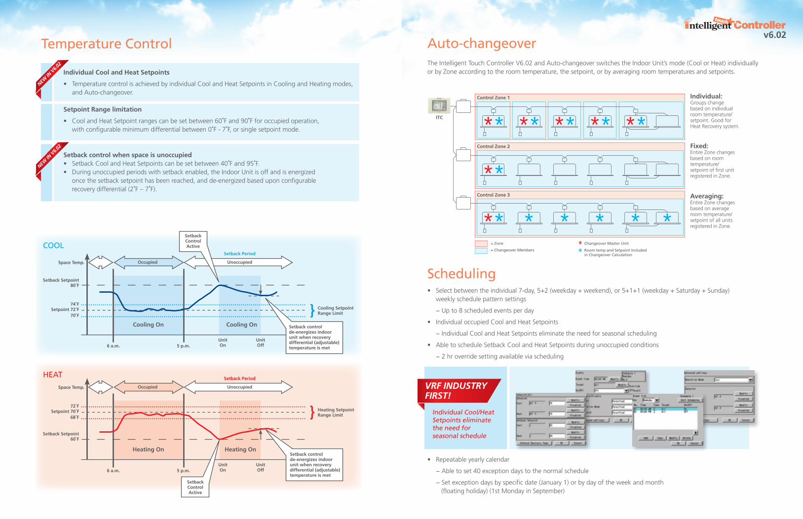
Auto-changeover The Intelligent Touch Controller V6.02 and Auto-changeover switches the Indoor Unit’s mode (Cool or Heat) individually or by Zone according to the room temperature, the setpoint, or by averaging room temperatures and setpoints.
Scheduling• Selectbetweentheindividual7-day,5+2(weekday+weekend),or5+1+1(weekday+Saturday+Sunday) weekly schedule pattern settings
− Up to 8 scheduled events per day
• IndividualoccupiedCoolandHeatSetpoints
− Individual Cool and Heat Setpoints eliminate the need for seasonal scheduling
• AbletoscheduleSetbackCoolandHeatSetpointsduringunoccupiedconditions
− 2 hr override setting available via scheduling
• Repeatableyearlycalendar
− Able to set 40 exception days to the normal schedule
− Set exception days by specific date (January 1) or by day of the week and month (floating holiday) (1st Monday in September)
individual:Groups change based on individual room temperature/setpoint. Good for Heat Recovery system.
Fixed:Entire Zone changes based on room temperature/setpoint of first unit registered in Zone.
averaging:Entire Zone changes based on average room temperature/setpoint of all units registered in Zone.
Changeover Master Unit= Zone
Room temp and Setpoint Included in Changeover Calculation
= Changeover Members
Control zone 1
itC
Control zone 2
Control zone 3
COOL
Individual Cool/Heat Setpoints eliminate the need for seasonal schedule
HEATVRF IndustRy FIRst!
v6.02Temperature Control
individual Cool and Heat setpoints
• TemperaturecontrolisachievedbyindividualCoolandHeatSetpointsinCoolingandHeatingmodes, and Auto-changeover.
setpoint range limitation
• CoolandHeatSetpointrangescanbesetbetween60˚F and 90˚F for occupied operation, with configurable minimum differential between 0˚F-7˚F, or single setpoint mode.
setback control when space is unoccupied • SetbackCoolandHeatSetpointscanbesetbetween40˚F and 95˚F. • Duringunoccupiedperiodswithsetbackenabled,theIndoorUnitisoffandisenergized oncethesetbacksetpointhasbeenreached,andde-energizedbaseduponconfigurable recovery differential (2˚F–7˚F).
new In
V6.0
2
new In
V6.0
2
Web Browser Software (optional)Monitor and control your VRV System via your Internet browser− Expanded web access configurations available for configurable client access − E-mail notification of system and equipment maintenance and/or issues
LAN/Internet
Network Switch/Router
Intelligent Touch Controller Outdoor Unit
Indoor Units
Icon View – Zone / Group List View – Zone / Group
Schedule Settings Scheduling Pattern Change
User’s Computer
Ethernet
Remote Monitoring / Maintenance
*Each Intelligent Touch Controller requires the Web/E-mail Software option for monitoring and control.
Unified Monitoring and Control*
Network/Internet
Property Manager / Engineering
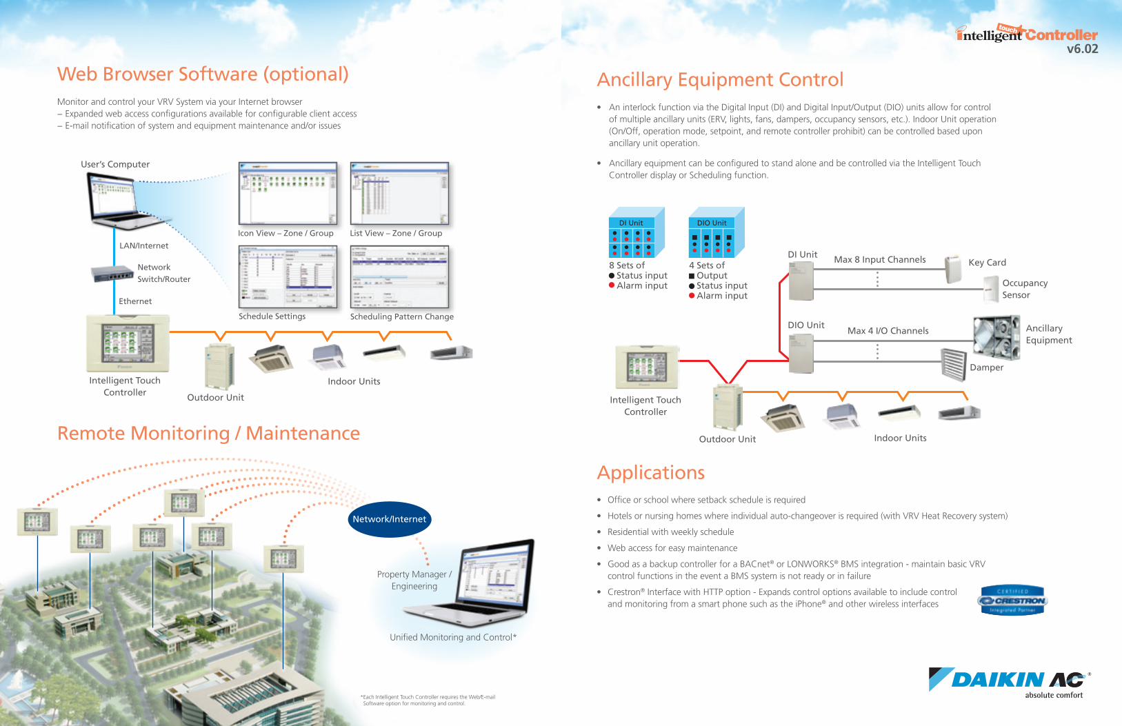
Ancillary Equipment Control• AninterlockfunctionviatheDigitalInput(DI)andDigitalInput/Output(DIO)unitsallowforcontrol
of multiple ancillary units (ERV, lights, fans, dampers, occupancy sensors, etc.). Indoor Unit operation (On/Off, operation mode, setpoint, and remote controller prohibit) can be controlled based upon ancillary unit operation.
• AncillaryequipmentcanbeconfiguredtostandaloneandbecontrolledviatheIntelligentTouchController display or Scheduling function.
Applications• Officeorschoolwheresetbackscheduleisrequired
• Hotelsornursinghomeswhereindividualauto-changeoverisrequired(withVRVHeatRecoverysystem)
• Residentialwithweeklyschedule
• Webaccessforeasymaintenance
• GoodasabackupcontrollerforaBACnet® or LONWORKS®BMSintegration-maintainbasicVRV controlfunctionsintheeventaBMSsystemisnotreadyorinfailure
• Crestron® Interface with HTTP option - Expands control options available to include control and monitoring from a smart phone such as the iPhone® and other wireless interfaces
v6.02
8 Sets of Status input Alarm input
DI Unit
4 Sets of Output Status input Alarm input
DIO Unit
Intelligent Touch Controller
Outdoor Unit Indoor Units
Max 8 Input Channels
Occupancy Sensor
Key Card
DIO Unit
DI Unit
Max 4 I/O Channels Ancillary Equipment
Damper

ModelItem Description
Description
All Daikin Industries locations and subsidaries in Japan have received environmental management system standard ISO 14001 certification.
Daikin Industries, Ltd.Domestic GroupCertificate Number: EC99J2044
Daikin AC (Americas), Inc.1645 Wallace Drive, Suite 110Carrollton, TX 75006 [email protected]
PCITUSE11-12C
The air conditioners manufactured by Daikin Industries have received ISO 9000 series certification for quality assurance.
Certificate Numbers:(ISO 9001) JMI-0107 (ISO 9001) JQA-1452
About ISO 14001
ISO 14001 is the standard defined by the International Organization for Standardization (ISO) relating to environmental management systems. Our group has been acknowledged by the internationally accredited compliance organization as having an appropriate program of environmental protection and activities to meet the requirements of ISO 14001.
Dealer Information
Daikin’s products are subject to continuous improvements. Daikin reserves the right to modify product design, specifications and information in this brochure without incurring any obligations.
* Pulse input from KWh meter requirements: 1 pulse to 1KWh or 10KWh. Pulse width must be between 40-400 msec. Non voltage, normally open semi-conductor type.** The Power Proportional Distribution (PPD) feature supplies the user with a reasonably calculated apportionment of the total power consumption by the Daikin air-conditioning system. Because input to the PPD includes measured pulses in the refrigerant system and because the air-conditioning system includes a number of variables, including operating temperatures and pressures, piping length, heat exchange rates and others, no meter-type apportionment of individual users’ consumption can be made. However, the PPD feature provides an apportionment methodology that uses highly advanced technology applied to the many variables in an air-conditioning system.
Intelligent Touch Controller DIII-Net Plus Adapter
Surrounding temperature
Humidity
H x W x D (inch)
Size/Number of pixels/Number of colors
Touch panel input
Maximum number of Indoor Units
Maximum number of Outdoor Units
F1F2 (Daikin DIII-Net communications)
10BASE-T (Ethernet communication)
PCMCIA slot (for flash memory card)
RS232C (for DCS601A72 connection)
DI (Digital input for forced shutdown)
PI (Pulse input) *
Model
Power supply
Power consumption
Operating conditions
Dimensions
LCD touch panel
Accessible units
Interfaces
Input terminals
EMC certification
Option Software
Unification Adapter
Installation box
Interface Adapters
Digital input (DI) unit
Digital input/output (DIO) unit
DCS002A71
DCS004A71
DCS007A51
DCS302A72
KJB411A
KRP928BB2S
DEC101A51-US2
DEC102A51-US2
Power Proportional Distribution (PPD)**
Web/E-mail Software (Java plugin - JSE 5.0 or later is required)
HTTP Interface software (for Home Automation System Integration)
Unified Start / Stop through outside signal
For wall mounted installation of Intelligent Touch Controller
For connection to Daikin Mini-Split system (connect to Indoor Unit)
8 sets of Operation status input and Alarm input
4 sets of Control output, Operation status input and Alarm input
DCS601C71
AC 24V 60Hz
10 W maximum (20VA or more transformer)
32˚ F to 104˚ F
Less than 85% RH (non condensing)
5 25/32 x 9 1/16 x 4 7/32
5.7 inches/QVGA 320x240/4,096
10 bit encoded analog input
64 addressed Indoor Unit Groups(maximum 128 actual Indoor Units)
10
1
1(RJ-45)
1
1 (Dsub-9 Male)
1
3
FCC Part 15 Subpart B Class A
DCS601A72
AC 24V 60Hz
5 W maximum (20 VA or more transformer)
14˚ F to 104˚ F
20% to 90% RH (non condensing)
7 15/32 x 6 3/16 x 1 21/32
-
-
64 addressed Indoor Unit Groups(maximum 128 actual Indoor Units)
10
1
-
-
1 (RJ-45) 32 ft cable included
-
3
FCC Part 15 Subpart B Class A
Configuration and engineering for each project is necessary.
Model
Options for Intelligent Touch Controller
Specifications
Other OptionsItem
v6.02
© 2011 Daikin Industries, Limited.
Daikin®, Daikin® AC, Absolute Comfort, and its design, VRV, REFNET, Quaternity, Daikin Altherma are trademarks of Daikin Industries, Limited. LonWorks® and LON® are registered trademarks of Echelon Corporation. BACnet® is a Data Communications Protocol for Building Automation and Control Networks, developed under the auspices of the American Society of Heating, Refrigeration and Air-Conditioning Engineers (ASHRAE).
Recommended