User’s Manual
Digital Force Gauge

Contents
1. Introduction 1 2. Operations 2.1 Choose model 4 2.2 Choose measuring heads 4 2.3 Power on/off 4 2.4 Testing 5 2.5 Hand-held or Mounting 6 2.6 Storage 6 2.7 Browse and Printing 6 3. Menus 3.1 Structure 7 3.2 Measurement 8 3.2.1 Unit 3.2.2 Group 3.2.3 Tolerance 3.2.4 Test Mode 3.2.5 Peak Time 3.2.6 Alarm 3.3 Memory 10 3.3.1 Storage Mode 3.3.2 Browse Data 3.3.3 Delete Data
3.4 Printing 11 3.5 System Setting 13 3.5.1 Display Mode 3.5.2 Power Off 3.5.3 Backlight 3.5.4 Key Tone 3.5.5 Date/Time 3.5.6 Password 3.5.7 Key Setting 3.5.8 Default Setting 3.6 Language 15 3.7 Information 15 4 External Interface 4.1 USB Port 16 4.2 Multifunction Port 16 5 Maintain and Calibration 5.1 Charging 18 5.2 Calibration 18 Appendix A-1 Packing List 20 A-2 Dimensions 21 Warranty Card 22

Please Carefully Read This First
●Operators should wear protection such as a mask and gloves in case pieces or components break away from the unit under test. ●Whether the unit is ON or OFF, DO NOT exceed the capacity of the gauge. NEVER exceed 150% of the rated capacity, or the load cell will be damaged. At 110% of the rated capacity, the display will flash a warning. ●When mounting the Digital Force Gauges, use M6 mounting screws with a maximum insertion depth of 7 mm into the gauge. ●Hand tightens adapters, DO NOT use tools. Do not use damaged clamp. ●Measure in line tension and compression forces only. DO NOT attempt to measure forces at an angle to the measuring shaft – damage to load cell and/or shaft may result. ●Do not attempt to repair or alter this instrument. Warranty will be voided and damage to the unit may result. ●Use and store within the stated temperature and humidity ranges, or damage and failure may result. ●If not using for extended periods of time, recharge it for every 2 to 3 months, or remove the batteries to prevent potential battery leakage from causing product damage.

1. Introduction
1.1 Overview Fig.1-1.
1.2 LCD Screen See Fig.1-2.
1. Battery icon: Battery level or charging status,Flashes when needs to be recharged.
2.Tolerance alarm Indicator: “ ”:
under lower limit; “ ”: between lower limit
and upper limit; “ ”: over upper limit
Measuring Shaft
LCD Screen
Touch Pad
USB Port Multifunction Port
Fig. 1-1
Fig. 1-2
- 1 -

3. Direction Icon: “ ” tension, “ ” compression. 4. Test Mode Icon: Three measurement modes. Track, Peak and Auto Peak. 5. Current measured value 6. Analog bar: Indicates current position in whole capacity. When the bar enters the area enclosed by
dotted line, means overload.
7. Saving icon: Indicates data is being saved. 8. System time. 9. Units.
1.3 Touch Pad
Power: Push for 2 seconds to power On or Off. During Measurement: Print the current force value or store data, depending on the key setting. (See3.5.7 Key Setting) In Menus: Back or Exit. During Measurement: Enter the menus. In Menus: Select or Enter. During Measurement: Track mode-Zeroing. Peak & Auto Peak modes-Resets the peak value. In Menus: Moves selection up or increases the value.
During Measurement: Changes Test Mode from Track, Peak or Auto Peak In Menus: Moves selection down or decreases the value.
- 2 -

1.4 Specifications Accuracy ± 0.2% F.S. Selectable Units mN, N, gf, kgf, ozf, and lbf.(Selectable) Display 160*128 dot matrix LCD with LED Backlight Overload 150% of F.S. (LCD flashes beyond 110% of F.S.) Temperature Effects <0.03% FS per °C Measurement Mode Peak, Autopeak or Track Mode Set Point Tolerance Alarm Sampling Rate 2000 Hz Display Update 10 times/sec. Memory 1000 data Power 3.6VDC Ni-MH rechargeable batteries Battery Life Approximately 16 hours continuous use per full charge Charger / Adaptor Universal USB/BM charger, Input:110~240VAC Outputs USB, RS232, Set points output
Environment Operating: -10 to 40°C, 20 to 80% RH Storage : -20 to +50°C , 5 to 95%RH
Dimensions 145*73*35.5 Weight: 0.7 kg (1.5 lb)
Accessories AC adapter/charger,6 attachments: hook, flat tip, conical tip, chisel tip, notched tip, extension shaft
The capacity and resolution is in table on back cover.
- 3 -

2. Operations 2.1 Choose model This series force gauge has a variety of models can be selected, different models corresponding to different range and resolution, as shown in table on back cover of this manual. Select the appropriate model based on practical need before use. DO NOT exceed the capacity of the gauge, or it may damage the force gauge forever. 2.2 Choose measuring heads In order to complete the test work convenient, the force gauge equipped with a variety of measuring heads (adapters). Select the appropriate measuring heads according to the actual need.
Flat tip Notched tip Conical tip chisel tip Hook Extension shaft
Fig. 2-1
2.3 Power on/off
Touch for 2 seconds to power On or Off.
After switching the instrument on, you should check the model wheith it is you want. Check Battery Icon. If the power is low, should be recharged.
- 4 -

2.4 Testing
After completion of the test preparation, testing can be done.
2.4.1 Measuring heads Select the appropriate measuring head, install it in the gauge's measurement axis. Tighten it by hand, without the use of tools. Do not use a deformed or damaged measuring head. NOTE: Do not use tools to vigorously tighten the measuring head, otherwise it will damage the force gauge.
2.4.2 Units The force gauge has a variety of measurement units, select the appropriate unit of force. Under the measure interface, press the Menu key to enter the menu interface (See 3.2.1 Unit )
2.4.3 Test Mode
This series force gauge has 3 kinds of measurement test mode can choose.
You can select a Measure Mode by touching under the measure interface, Or can change it in menus (See 3.2.4 Test Mode ).
Track: The real time measuring mode, under this mode, press the zero key the force gauge
will be cleared (remove tare). Peak: Peak readings will not change until a higher value is measured. Under this mode,
touch the zero key the force gauge will update the display immediately. Auto-Peak: In this mode, the gauge display a peak value of force in a fixed duration. The duration time can be set in menus.
- 5 -

2.4.4 Tolerance Limit The tolerance limits can be set for GO/NG measurement also. See for detail.
If you set the alarm on and a valid limit, The icon will be displayed for within limit, lower than lower limit or exceed upper limit.
2.4.5 Zeroing
Touch to clear the force gauge in track mode for removing the tare. 2.5 Hand-held or Mounting The force gauge is a portable Instrument, you can do the testing hand-held, or you also can install the force gauge on the test stand so as to obtain accurate measurement results. There are 6 M4.0 mounting screw holes on the back,can be fixed on the test stand, shown as Fig. 2-2. NOTE: The depth of the mounting hole is 8.0mm, please choose the appropriate screws, screw into the depth of the force gauge shall not be greater than 7mm. 2.6 Storage Measured results can be stored in the force gauge, so that you can review or print them later.
Under the measure interface, touch to save value measured, and the save icon will be displayed. 2.7 Browse and Printing The values saved in memory can be reviewed in Browse function. The data in memory can be printed to a report.
- 6 -

3. Menus
3.1 Structure The Force Gauge has multi-level menu interface(Table
3-1).
From the home screen, touch “ ” to enter the Menu. (Fig. 3-1、Fig. 3-2)
Touch or can move selection. Then
touch can enter the next layer of menu.
Touch can cancel the setting or exit.
In number input, touch can increase the number,
and touch can change to another digit or item.
Men
u
Measurement
Unit Group Tolerance Test Mode Peak Time Alarm
Memory
Storage Mode Browse All Browse Selected Delete Selected Delete All
Printing Print Recent Print Selected Print All
System
Display Mode Power Off Backlight Key Tone Date/Time Password Key Setting Default Setting
Language Calibration Information
Table 3-1
Fig. 3-1
Fig. 3-2
- 7 -

3.2 Measurement The Measurement contains six selectable items: Unit,
Group,Tolerance, Test mode, Peak Time and Alarm. (Fig,
3-3)
3.2.1 Unit The measuring unit can be selected under this menu.
Different range models may have different unit selection
capabilities. See Fig.3-4.
3.2.2 Group When several test samples need to be measured, the
samples can be coded into groups. The range is 01-99.
See Fig.3-5.
3.2.3 Tolerance In the Tolerance menu, program upper and lower limit for
GO/NG Measurement.
Fig. 3-4
Fig. 3-5
Fig. 3-3
- 8 -

The upper limit value must be greater than the lower limit,
and both limit value can not be greater than 110% of the
rated capacity. See Fig.3-6.
3.2.4 Test Mode
Test mode can be selected. There are three kinds of mode:
Track, Peak and Auto Peak. (Fig. 3-7)
3.2.5 Peak Time
If AutoPeak moe is used, you can set the peak value
capturing time interval- Peak Time. Default setting of Peak
Time is 5 sec.
The range is 1~99 seconds. (Fig. 3-8)
3.2.6 Alarm
You can turn on/off the sound of tolerance alarm( Fig.3-9).
The sound for overload alarm cannot be turned off.
Fig. 3-6
Fig. 3-7
Fig. 3-8
Fig. 3-9
- 9 -

3.3 Memory In this menu, you can set the memory mode, browse the
data in memory or delete it/them.
3.3.1 Storage Mode
There are two storage mode can be selected, Single and
Series. Single: The current value displayed can be saved
when touch . This mode can be use in all 3 test mode.
Series: Continuous storage mode, only in Auto Peak
mode is effective. When a peak capture time interval
is reached, the peak value is saved, no need touch
any key (Fig. 3-11).
3.3.2 Browse Data
You can browse the data in memory with two method,
Browse All or Browse Selected. (Fig.3-12,Fig3-13)
The greatest number is the most recent data.
Fig. 3-10
Fig. 3-11
Fig. 3-12
Fig. 3-13
- 10 -
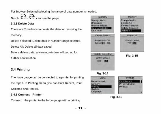
For Browse Selected selecting the range of data number is needed.
Touch or can turn the page.
3.3.3 Delete Data
There are 2 methods to delete the data for restoring the
memory.
Delete selected: Delete data in number range selected.
Delete All: Delete all data saved.
Before delete data, a warning window will pop up for
further confirmation.
3.4 Printing The force gauge can be connected to a printer for printing
the report. In Printing menu, you can Print Recent, Print
Selected and Print All.
3.4.1 Connect Printer
Connect the printer to the force gauge with a printing
Fig. 3-14
Fig. 3-15
Fig. 3-16
- 11 -

cable. Then turn on the power of printer.
3.4.2 Printing Setup
Print Recent: Print some data measured recently(Fig.
3-17)
Print Selected: Print data in a number range(Fig. 3-18).
Print All: Print all data in memory(Fig. 3-19).
It may take a long time to print all the data and need many
printing paper, so a prompt window will pop out to ask for
confirmation.
The style of test
report is shown as
Fig.3-20.
Fig. 3-20
Fig. 3-17
Fig. 3-18
Fig. 3-19
- 12 -

3.5 System Setting 3.5.1 Display Mode LCD display direction can be transformed according to the position of force gauge automatically. You can set it to Obverse or Reverse and not Automatic.
3.5.2 Power Off
The force gauge can turn the power off automatically, some time interval after no measuring and no any operation. 5 minutes is default. You can change it for a longer or shorter standby.
3.5.3 Backlight
The force gauge can turn off backlight, some time interval
after no measuring and no any operation. You can select this
time or turn it on or off always.(Fig. 3-24)
3.5.4 Key Tone(Fig. 3-25)
3.5.5 Date/Time (Fig. 3-26)
Fig. 3-21
Fig. 3-22
Fig. 3-23
Fig. 3-24
- 13 -

3.5.6 Password
Some operations of force gauge may need to enter a password to prevent mistake or unexpected change. The default System password is“123”. You can change it to your favorite. You should enter the old password first, then enter a new one.
3.5.7 Key Setting
The key is a multifunction key,
It can be set as "store the current display value(Storage)" or
"print the recent data (Print)".
"Storage" is default.
Fig. 3-28
Fig. 3-25
Fig. 3-26
Fig. 3-27
- 14 -

3.5.8 Default Setting
When the artificial error, and do not know how to restore, the gauge can be restored to factory settings. it
will lose that some imformation set by customs.Carefully
use this function!
Restoring to Default Setting, the password must be enter
and a prompt must be confirmed. 3.6 Language Here you can select the language appropriate. 3.7 Information Some information such as the logo, the model, the version of program and the series number are displayed here.
Fig. 3-29
Fig. 3-30
- 15 -
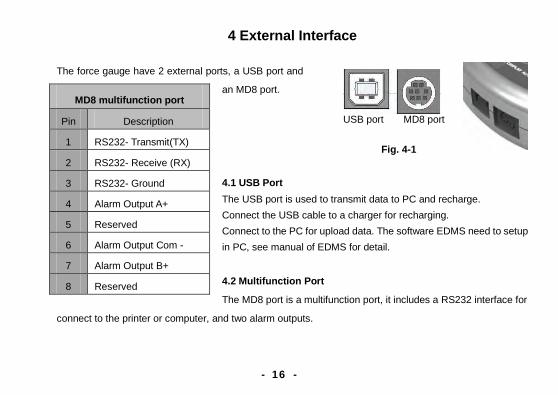
4 External Interface
The force gauge have 2 external ports, a USB port and
an MD8 port.
4.1 USB Port The USB port is used to transmit data to PC and recharge. Connect the USB cable to a charger for recharging. Connect to the PC for upload data. The software EDMS need to setup in PC, see manual of EDMS for detail.
4.2 Multifunction Port
The MD8 port is a multifunction port, it includes a RS232 interface for
connect to the printer or computer, and two alarm outputs.
MD8 multifunction port
Pin Description
1 RS232- Transmit(TX)
2 RS232- Receive (RX)
3 RS232- Ground
4 Alarm Output A+
5 Reserved
6 Alarm Output Com -
7 Alarm Output B+
8 Reserved
USB port MD8 port
Fig. 4-1
- 16 -

You can change the baud rate in menus. shown in Fig.4-2. Alarm output: There are two alarm outputs, you can connect them to the other equipment (such as test stand, PLC etc.), or connect to some alarm units.
! Maximum permissible voltage pin 7 to pin 6, pin 4 to pin 6: 35V; pin 6 to pin 7, pin 6 to pin 4: 6V.
Fig. 4-3
RS232 Specifications
Data word length 8 bits Stop bit 1bit Parity None
Baud rate 9600,19200, 38400
Hardware Flow Control
None
Fig. 4-2
- 17 -

5 Maintain and Calibration 5.1 Charging
When the battery are low, the icon “ ” will be displayed. The batteries should be charged immediately. Connect the gauge and the charger use the USB cable, and then connect the charger with AC socket to start charging. It takes about 3~4 hours for fully charging. You can also use other USB device (e.g. Laptop PC) to recharge the gauge.
5.2 Calibration Because of the sensor material performance or the influence of external factors, there may be errors in a certain range after a period of time use. Should send the force gauge to a specialized testing organization for calibration.
Fig. 5-2
❶Calibration times ❷Current measuring value ❸Standard value input
Fig. 5-3
Fig. 5-1
- 18 -

If you have some stansard force weights or the other standard load and some test stand, you may calibrate it also.
① Mount the force gauge.
② Remove the tare by use of the key . ③ Enter Calibration interface, as Fig 5-2.
The calibration interface is shown as Fig 5-3.
④ Load a standard force.Now the value in standard input
area is just equal to the current measured value.Wait a moment for the force stability.
⑤ Touch and to input the stansard force value.
⑥ Touch to enter the next calibration. Touch can interrupt the calibration.
When the 5 times calibration had been finished or be interrupted, a confirm window will pop up to ask for
save or not save the calibration. (Fig. 5-3)
Touch or to select, then press . If "YES" is selected, "Calibrate complete!" is displayed. NOTE: ①Set the unit of force to the unit used in calibration previously(as shown in 3.2.1 Unit) ②Ensure that the tare weight of attachment has been remove before calibration. ③You can do any point or points calibration from 1 to 5 point., we recommend 5 points calibration.
Fig. 5-4
- 19 -

Appendix A-1 Packing List
- 20 -

A-2 Dimensions
- 21 -
Recommended