H i g h E f f i c i e n c y S o l u t i o n s
NO POWER
& SIGNAL
CABLES
TOGETHER
READ CAREFULLY IN THE TEXT!
MPXPROElectronic controller
User manual

3
ENG
MPXPRO - + 0300055EN rel. 1.4 - 29.09.2015
WARNING
CAREL developed its products thanks to the several years of experience in the
HVAC fi eld, continuous investment in technological innovation of the product,
rigorous quality procedures and processes with in-circuit and function tests on
100% of its production, as well as the most innovative production technologies
available on the market. CAREL and its branch offi ces/affi liates do not guarantee,
in any case, that all the aspects of the product and the software included in the
product will respond to the demands of the fi nal application, even if the product is
built according to state-of-the-art techniques.
The client (builder, developer or installer of the fi nal equipment) assumes every
responsibility and risk relating to the confi guration of the product in order to reach
the expected results in relation to the specifi c fi nal installation and/or equipment.
CAREL, in this case, through specifi c agreements, can intervene as consultant for
the positive result of the fi nal start-up machine/application, but in no case can it be
held responsible for the positive working of the fi nal equipment/apparatus.
The CAREL product is a state-of-the-art product, whose operation is specifi ed in the
technical documentation supplied with the product or can be downloaded, even
prior to purchase, from the website www.carel.com.
Each CAREL product, in relation to its advanced technological level, needs a phase
of defi nition / confi guration / programming / commissioning so that it can function
at its best for the specifi c application. The lack of such phase of study, as indicated
in the manual, can cause the fi nal product to malfunction of which CAREL cannot
be held responsible.
Only qualifi ed personnel can install or carry out technical assistance interventions
on the product.
The fi nal client must use the product only in the manner described in the
documentation related to the product itself.
Without excluding proper compliance with further warnings present in the manual,
it is stressed that in any case it is necessary, for each CAREL product:
• Not allow the electronic circuits getting wet. Rain, humidity and all types of
liquids or condensate contain corrosive mineral substances that can damage
the electrical circuits. In any case, the product should be used and stored in
environments that respect the temperature and humidity limits specifi ed in the
manual;
• Not to install the device in a particularly hot environments. Temperatures that
are too high can shorten the duration of the electronic devices, damaging them
and distorting or melting the parts in plastic. In any case, the product should be
used and stored in environments that respect the temperature and humidity
limits specifi ed in the manual;
• Not to try to open the device in any way diff erent than that indicated in the
manual;
• Not to drop, hit or shake the device, because the internal circuits and
mechanisms could suff er irreparable damage.
• Not to use corrosive chemical products, aggressive solvents or detergents to
clean the device;
• Not to use the product in application environments diff erent than those
specifi ed in the technical manual.
All the above reported suggestions are also valid for the control, serial boards,
programming keys or however for any other accessory in the CAREL product
portfolio.
CAREL adopts a continuous development policy. Therefore, CAREL reserves the
right to carry out modifi cations and improvements on any product described in
this document without prior notice.
The technical data in the manual can undergo modifi cations without forewarning.
The liability of CAREL in relation to its products is specifi ed in the CAREL general
contract conditions, available on the website www.carel.com and/or by specifi c
agreements with customers; specifi cally, to the extent where allowed by applicable
legislation, in no case will CAREL, its employees or subsidiaries be liable for any
lost earnings or sales, losses of data and information, costs of replacement
goods or services, damage to things or people, downtime or any direct, indirect,
incidental, actual, punitive, exemplary, special or consequential damage of any
kind whatsoever, whether contractual, extra-contractual or due to negligence, or
any other liabilities deriving from the installation, use or impossibility to use the
product, even if CAREL or its subsidiaries are warned of the possibility of such
damage.
DISPOSAL
INFORMATION FOR THE USERS REGARDING THE CORRECT HANDLING OF WASTE ELECTRIC AND ELECTRONIC EQUIPMENT (WEEE)
With reference to European Parliament and Council Directive 2002/96/EC issued
on 27 January 2003 and the related national implementation legislation, please
note that:
• WEEE cannot be disposed of as municipal waste, said waste must be collected
separately;
• the public or private waste collection systems defi ned by local legislation must
be used. Moreover, the equipment can be returned to the distributor at the end
of its working life when buying new equipment;
• this equipment may contain dangerous substances: improper use or incorrect
disposal of such may have negative eff ects on human health and on the
environment;
• the symbol (crossed-out wheeley bin) shown on the product or on the
packaging and on the instruction sheet indicates that the equipment has been
introduced onto the market after 13 August 2005 and that it must be disposed
of separately;
• in the event of illegal disposal of electrical and electronic waste, the penalties are
specifi ed by local waste disposal legislation.
Materials warranty: 2 years (from the date of production, excluding consumables).
Type-approval: the quality and safety of CAREL S.P.A. products are guaranteed by
the design system and ISO 9001 certifi ed production.
NO POWER
& SIGNAL
CABLES
TOGETHER
READ CAREFULLY IN THE TEXT!
WARNING: separate the probe cables and the digital input cables as much
as possible from the inductive load and power cables to prevent possible
electro-magnetic interference. Never introduce power cables and signal cables
(including those of electric control board) into the same cable troughs.
HACCP: caution
The Food Safety programs based on HACCP procedures and on certain national
standards, require that the devices used for food preservation are periodically
checked to make sure that the measuring errors are within the allowed limits of
the application of use.
Carel recommends compliance with the indications of European standard
“Temperature recorders and thermometers for transport, storage and distribution
of chilled, frozen, deep-frozen/ quick-frozen food and ice cream – PERIODIC
VERIFICATION “, EN 13486 -2001 (or subsequent updates)or similar standards and
prescriptions applicable in the country of use.
The manual contains further indications regarding technical feature, proper
installation and confi guration of the product.
HACCP International Food Safety Certifi cation Systems “Food Safe Equipment Material and Services” Certifi cato I-PE-705-CIS-RG-01b (valid until 31/12/2015)http://www.haccp-international.com/
This product is approved for the use in food preservation
applications in compliance with the strictest standards in
the sector.

5
ENG
MPXPRO - + 0300055EN rel. 1.4 - 29.09.2015
Content
1. INTRODUCTION 7
1.1 Models ............................................................................................................... 81.2 Functions and main characteristics ............................................................. 8
2. INSTALLATION 11
2.1 MPXPRO: DIN rail assembly and dimensions ........................................ 112.2 Main board: description of the terminals ................................................ 122.3 E2V driver expansion board (MX3OPSTP**): terminals and connec-tions 132.4 PWM driver expansion board (MX3OPPWM**): terminals and con-nections ..................................................................................................................... 132.5 Expansion board 0 to 10 Vdc output (MX*OPA10**): terminals and connections .............................................................................................................. 132.6 Functional diagrams ..................................................................................... 142.7 Connecting the MCHRTF**** module .................................................... 142.8 General connection diagram .................................................................... 152.9 Installation ...................................................................................................... 162.10 Programming key (copy set-up)................................................................ 162.11 Commissioning tool (VPM- Visual Parameter Manager) ......................172.12 Setting the default parameters/loading the parameter sets ................17
3. USER INTERFACE 18
3.1 User terminal and remote display ............................................................. 183.2 Keypad ........................................................................................................... 183.3 Programming ................................................................................................. 193.4 Ex.: setting current date/time and day/night time bands ...................203.5 Copy parameters from Master to Slave (Upload) ................................. 213.6 Using the remote control (accessory) ...................................................... 21
4. COMMISSIONING 23
4.1 Confi guration .................................................................................................234.2 Recommended initial confi guration .........................................................234.3 Guided commissioning procedure (user terminal/remote display) .244.4 Checks after commissioning .......................................................................25
5. BASIC FUNCTIONS 26
5.1 Probes (analogue inputs)............................................................................265.2 Digital inputs .................................................................................................275.3 Analogue outputs ..........................................................................................295.4 Digital outputs ...............................................................................................305.5 Control ............................................................................................................. 315.6 Defrost .............................................................................................................325.7 Evaporator fans ..............................................................................................355.8 Electronic valve ..............................................................................................36
6. ADVANCED FUNCTIONS 37
6.1 Probes (analogue inputs)............................................................................ 376.2 Digital inputs ..................................................................................................386.3 Analogue outputs ..........................................................................................386.4 Digital outputs ...............................................................................................396.5 Control .............................................................................................................396.6 Compressor ....................................................................................................426.7 Defrost .............................................................................................................426.8 Evaporator fans ..............................................................................................446.9 Electronic valve .............................................................................................446.10 Protectors ....................................................................................................... 476.11 Refrigerant fl ow control ...............................................................................49
7. OPTIONAL CONFIGURATIONS 50
7.1 Other confi guration parameters ................................................................50
8. TABLE OF PARAMETERS 51
9. ALARMS AND SIGNALS 56
9.1 Signals ..............................................................................................................569.2 Alarms ..............................................................................................................569.3 Display alarm log ..........................................................................................569.4 HACCP alarms and display .........................................................................569.5 Alarm parameters .........................................................................................589.6 HACCP alarm parameters and activating monitoring ...........................59
10. TECHNICAL SPECIFICATIONS 60
10.1 Cleaning the terminal ................................................................................... 6110.2 Purchase codes .............................................................................................. 6110.3 Food safety - HACCP ..................................................................................62

7
ENG
MPXPRO - + 0300055EN rel. 1.4 - 29.09.2015
refrigerant inlet
refr
ige
ran
t o
utl
et
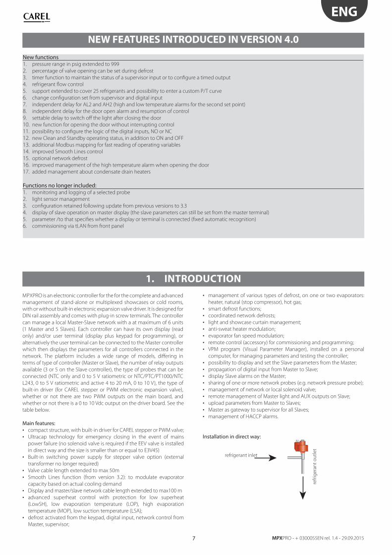
1. INTRODUCTION
MPXPRO is an electronic controller for the for the complete and advanced
management of stand-alone or multiplexed showcases or cold rooms,
with or without built-in electronic expansion valve driver. It is designed for
DIN rail assembly and comes with plug-in screw terminals. The controller
can manage a local Master-Slave network with a at maximum of 6 units
(1 Master and 5 Slaves). Each controller can have its own display (read
only) and/or user terminal (display plus keypad for programming), or
alternatively the user terminal can be connected to the Master controller
which then displays the parameters for all controllers connected in the
network. The platform includes a wide range of models, diff ering in
terms of type of controller (Master or Slave), the number of relay outputs
available (3 or 5 on the Slave controller), the type of probes that can be
connected (NTC only and 0 to 5 V ratiometric or NTC/PTC/PT1000/NTC
L243, 0 to 5 V ratiometric and active 4 to 20 mA, 0 to 10 V), the type of
built-in driver (for CAREL stepper or PWM electronic expansion valve),
whether or not there are two PWM outputs on the main board, and
whether or not there is a 0 to 10 Vdc output on the driver board. See the
table below.
Main features:• compact structure, with built-in driver for CAREL stepper or PWM valve;
• Ultracap technology for emergency closing in the event of mains
power failure (no solenoid valve is required if the EEV valve is installed
in direct way and the size is smaller than or equal to E3V45)
• Built-in switching power supply for stepper valve option (external
transformer no longer required)
• Valve cable length extended to max 50m
• Smooth Lines function (from version 3.2): to modulate evaporator
capacity based on actual cooling demand
• Display and master/slave network cable length extended to max100 m
• advanced superheat control with protection for low superheat
(LowSH), low evaporation temperature (LOP), high evaporation
temperature (MOP), low suction temperature (LSA);
• defrost activated from the keypad, digital input, network control from
Master, supervisor;
• management of various types of defrost, on one or two evaporators:
heater, natural (stop compressor), hot gas;
• smart defrost functions;
• coordinated network defrosts;
• light and showcase curtain management;
• anti-sweat heater modulation;
• evaporator fan speed modulation;
• remote control (accessory) for commissioning and programming;
• VPM program (Visual Parameter Manager), installed on a personal
computer, for managing parameters and testing the controller;
• possibility to display and set the Slave parameters from the Master;
• propagation of digital input from Master to Slave;
• display Slave alarms on the Master;
• sharing of one or more network probes (e.g. network pressure probe);
• management of network or local solenoid valve;
• remote management of Master light and AUX outputs on Slave;
• upload parameters from Master to Slaves;
• Master as gateway to supervisor for all Slaves;
• management of HACCP alarms.
Installation in direct way:
NEW FEATURES INTRODUCED IN VERSION 4.0
New functions1. pressure range in psig extended to 999
2. percentage of valve opening can be set during defrost
3. timer function to maintain the status of a supervisor input or to confi gure a timed output
4. refrigerant fl ow control
5. support extended to cover 25 refrigerants and possibility to enter a custom P/T curve
6. change confi guration set from supervisor and digital input
7. independent delay for AL2 and AH2 (high and low temperature alarms for the second set point)
8. independent delay for the door open alarm and resumption of control
9. settable delay to switch off the light after closing the door
10. new function for opening the door without interrupting control
11. possibility to confi gure the logic of the digital inputs, NO or NC
12. new Clean and Standby operating status, in addition to ON and OFF
13. additional Modbus mapping for fast reading of operating variables
14. improved Smooth Lines control
15. optional network defrost
16. improved management of the high temperature alarm when opening the door
17. added management about condensate drain heaters
Functions no longer included:1. monitoring and logging of a selected probe
2. light sensor management
3. confi guration retained following update from previous versions to 3.3
4. display of slave operation on master display (the slave parameters can still be set from the master terminal)
5. parameter /to that specifi es whether a display or terminal is connected (fi xed automatic recognition)
6. commissioning via tLAN from front panel
8
ENG
MPXPRO - +0300055EN rel. 1.4 - 29.09.2015
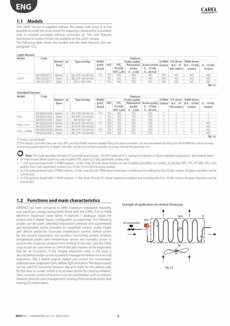
1.1 ModelsThe LIGHT version is supplied without the plastic side cover, it is not
possible to install the driver board for expansion valves and it is available
only in multiple packages without connector kit. The new features
introduced in version 4.0 are not available on the LIGHT version.
The following table shows the models and the main features, also see
paragraph 10.2:
Light VersionModel Code Features
Master/ Slave
rel. Type of relay RS485 & RTCBoard
Probe usable 2 PWM output
E2V driver & 0…10
Vdc output
PWM driver & 0…10 Vdc
output0…10 Vdc
outputNTC PTC,
Pt1000, NTC L243
Ratiometric probe
0…5 Vdc
Active probe 0…10 Vdc 4…20 mA
LIGHT
MX10M00EI11 Master 5 8A-2HP-16A-8A-8A Y(*) YES NO YES NO NO NO NO NO
MX10S00EI11 Slave 5 8A-2HP-16A-8A-8A I YES NO YES NO NO NO NO NO
MX10S10EI11 Slave 3 8A-0-16A-0-8A I YES NO YES NO NO NO NO NO
Tab. 1.a
Standard VersionModel Code Features
Master/ Slave
rel. Type of relay RS485 & RTCBoard
Probe usable 2 PWM output
E2V driver & 0…10
Vdc output
PWM driver & 0…10 Vdc
output0…10 Vdc
outputNTC PTC,
Pt1000, NTC L243
Ratiometric probe
0…5 Vdc
Active probe 0…10 Vdc 4…20 mA
FULL
MX30M21HO0 Master 5 8A-2HP-16A-8A-8A Y(*) YES YES YES YES Y I I I
MX30S21HO0 Slave 5 8A-2HP-16A-8A-8A I YES YES YES YES Y I I I
MX30S31HO0 Slave 3 8A-0-16A-0-8A I YES YES YES YES Y I I I
FULL + E2VMX30M25HO0 Master 5 8A-2HP-16A-8A-8A Y(*) YES YES YES YES Y Y I NO
MX30S25HO0 Slave 5 8A-2HP-16A-8A-8A I YES YES YES YES Y Y I NO
FULL + PWMMX30M24HO0 Master 5 8A-2HP-16A-8A-8A Y(*) YES YES YES YES Y I Y NO
MX30S24HO0 Slave 5 8A-2HP-16A-8A-8A I YES YES YES YES Y I Y NO
Tab. 1.b (Y: fi tted, I: can be fi tted)
(*) The Master controllers have the clock (RTC) and the RS485 interface already fi tted, the Slave controllers can become Masters by fi tting the MX3OP48500 card (accessory)
and setting a parameter (In). A Master controller can become a Slave controller by simply setting the parameter (In).
Note: The code identifi es the type of controller and outputs: the fi fth letter, M or S, represents a Master or Slave controller respectively; the seventh letter:
• 0= main board, driver board not pre-installed, NTC and 0 to 5 Vdc ratiometric probe only;
• 1= full optional board with 2 PWM outputs, 12 Vdc (max 20 mA), driver board not pre-installed, possibility to connect, as desired, NTC, PTC, PT1000, NTC L243
probes, 0 to 5 Vdc ratiometric probes, 0 to 10 Vdc or 4 to 20 mA active probes
• 4= full optional board with 2 PWM outputs, 12 Vdc (max 20 mA), PWM driver board pre-installed and including the 0 to 10 Vdc output, all types of probes can be
connected;
• 5= full optional board with 2 PWM outputs, 12 Vdc (max 20 mA), E2V driver board pre-installed and including the 0 to 10 Vdc output, all types of probes can be
connected.
1.2 Functions and main characteristics
MPXPRO has been designed to off er maximum installation fl exibility
and signifi cant energy saving when fi tted with the CAREL E2V or PWM
electronic expansion valve driver. It features 7 analogue inputs for
probes and 5 digital inputs, confi gurable by parameter. The following
probes can be used: saturated evaporation pressure and superheated
gas temperature probe, required for superheat control, outlet, intake
and defrost probe for showcase temperature control, defrost probe
for the second evaporator, two auxiliary monitoring probes, ambient
temperature probe, glass temperature sensor and humidity probe to
prevent the showcase windows from misting. In the later case the PWM
outputs can be used either to control the glass heaters or the evaporator
fans for air circulation. If the stepper expansion valve is not used, a
second defrost probe can be installed to manage the defrost on a second
evaporator. The 5 digital outputs (relays) can control the compressor/
solenoid valve, evaporator fans, defrost, light and alarm. The digital inputs
can be used for switching between day and night, for the defrost calls,
for the door or curtain switch or to activate alarms. By creating a Master/
Slave network, a series of functions can be coordinated, such as defrosts,
network solenoid valve management, sharing of the pressure probe, and
sharing of control status.
Example of application on vertical showcase:
SV (opzionale)
Sm E
Sr
Sd
EEV
Fig. 1.a
9
ENG
MPXPRO - + 0300055EN rel. 1.4 - 29.09.2015
Sm
Sr
Sd
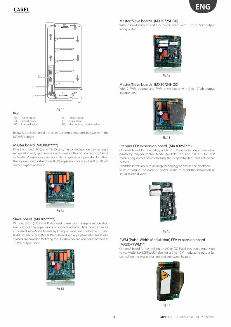
Fig. 1.b
Key:Sm Outlet probe Sr Intake probe
Sd Defrost probe E evaporator
SV Solenoid valve EEV electronic expansion valve
Below is a description of the series of components and accessories in the
MPXPRO range:
Master board (MX30M*****)Fitted with clock (RTC) and RS485 card, this can independently manage a
refrigeration unit, synchronise events over a LAN and connect to a CAREL
or Modbus® supervisory network. Plastic spacers are provided for fi tting
the for electronic valve driver (EEV) expansion board or the 0 to 10 Vdc
output expansion board.
Fig. 1.c
Slave board (MX30S*****)Without clock (RTC) and RS485 card, these can manage a refrigeration
unit without the supervisor and clock functions. Slave boards can be
converted into Master boards by fi tting in place (see photo) the RTC and
RS485 interface card (MX3OP48500) and setting a parameter (In). Plastic
spacers are provided for fi tting the EEV driver expansion board or the 0 to
10 Vdc output board.
Fig. 1.d
Master/Slave boards (MX30*25HO0) With 2 PWM outputs and E2V driver board with 0 to 10 Vdc output
incorporated.
Fig. 1.e
Master/Slave boards (MX30*24HO0)With 2 PWM outputs and PWM driver board with 0 to 10 Vdc output
incorporated.
Fig. 1.f
Stepper EEV expansion board (MX3OPST***).Optional board for controlling a CAREL E2V electronic expansion valve
driven by stepper motor. Model MX3OPSTP0* also has a 0 to 10 V
modulating output for controlling the evaporator fans and anti-sweat
heaters.
Available in version with ultracap technology to ensure the electronic
valve closing in the event of power failure to avoid the installation of
liquid solenoid valve.
Fig. 1.g
PWM (Pulse-Width Modulation) EEV expansion board (MX3OPPWM**) Optional board for controlling an AC or DC PWM electronic expansion
valve. Model MX3OPPWM0* also has a 0 to 10 V modulating output for
controlling the evaporator fans and anti-sweat heaters.
Fig. 1.h
10
ENG
MPXPRO - +0300055EN rel. 1.4 - 29.09.2015
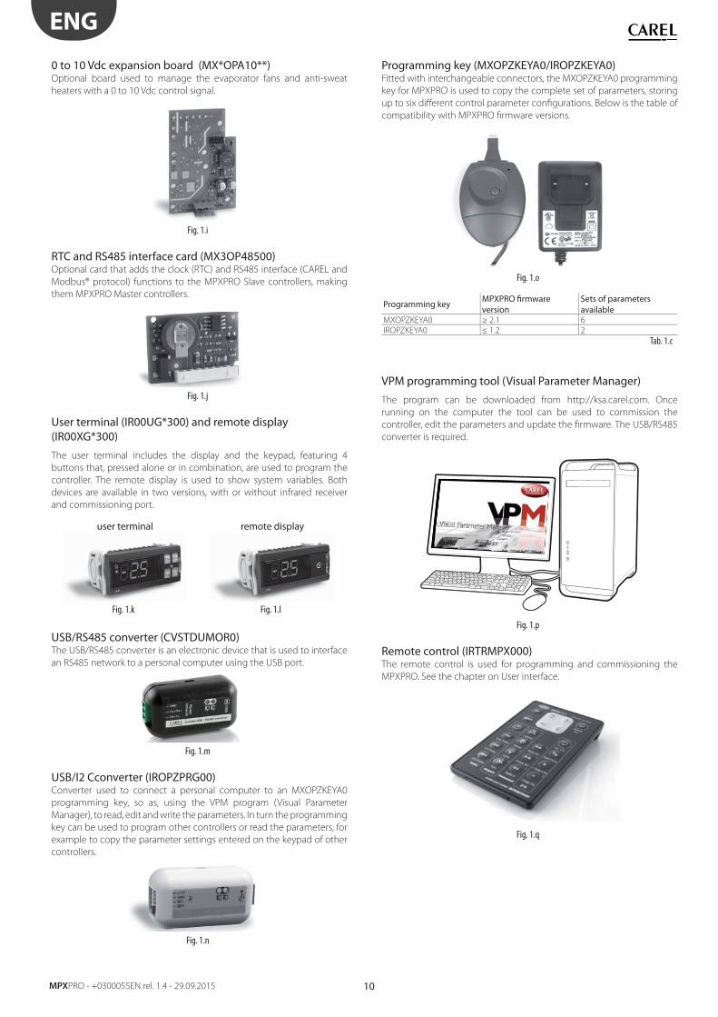
0 to 10 Vdc expansion board (MX*OPA10**) Optional board used to manage the evaporator fans and anti-sweat
heaters with a 0 to 10 Vdc control signal.
Fig. 1.i
RTC and RS485 interface card (MX3OP48500)Optional card that adds the clock (RTC) and RS485 interface (CAREL and
Modbus® protocol) functions to the MPXPRO Slave controllers, making
them MPXPRO Master controllers.
Fig. 1.j
User terminal (IR00UG*300) and remote display (IR00XG*300)
The user terminal includes the display and the keypad, featuring 4
buttons that, pressed alone or in combination, are used to program the
controller. The remote display is used to show system variables. Both
devices are available in two versions, with or without infrared receiver
and commissioning port.
user terminal remote display
Fig. 1.k Fig. 1.l
USB/RS485 converter (CVSTDUMOR0) The USB/RS485 converter is an electronic device that is used to interface
an RS485 network to a personal computer using the USB port.
Fig. 1.m
USB/I2 Cconverter (IROPZPRG00) Converter used to connect a personal computer to an MXOPZKEYA0
programming key, so as, using the VPM program (Visual Parameter
Manager), to read, edit and write the parameters. In turn the programming
key can be used to program other controllers or read the parameters, for
example to copy the parameter settings entered on the keypad of other
controllers.
Fig. 1.n
Programming key (MXOPZKEYA0/IROPZKEYA0)Fitted with interchangeable connectors, the MXOPZKEYA0 programming
key for MPXPRO is used to copy the complete set of parameters, storing
up to six diff erent control parameter confi gurations. Below is the table of
compatibility with MPXPRO fi rmware versions.
Fig. 1.o
Programming keyMPXPRO fi rmware version
Sets of parameters available
MXOPZKEYA0 ≥ 2.1 6
IROPZKEYA0 ≤ 1.2 2
Tab. 1.c
VPM programming tool (Visual Parameter Manager)
The program can be downloaded from http://ksa.carel.com. Once
running on the computer the tool can be used to commission the
controller, edit the parameters and update the fi rmware. The USB/RS485
converter is required.
Fig. 1.p
Remote control (IRTRMPX000)The remote control is used for programming and commissioning the
MPXPRO. See the chapter on User interface.
Fig. 1.q
11
ENG
MPXPRO - + 0300055EN rel. 1.4 - 29.09.2015
2. INSTALLATION
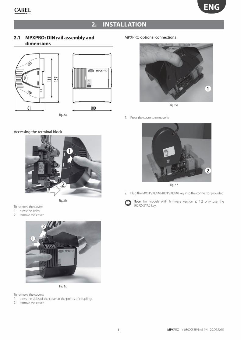
2.1 MPXPRO: DIN rail assembly and
dimensions
PUSH
137
111
81 109
MPXPRO
Highvoltage
Fig. 2.a
Accessing the terminal block
Fig. 2.b
To remove the cover:
1. press the sides;
2. remove the cover.
Fig. 2.c
To remove the covers:
1. press the sides of the cover at the points of coupling;
2. remove the cover.
MPXPRO optional connections
Fig. 2.d
1. Press the cover to remove it;
Fig. 2.e
2. Plug the MXOPZKEYA0/IROPZKEYA0 key into the connector provided.
Note: for models with fi rmware version ≤ 1.2 only use the
IROPZKEYA0 key.
1
2
12
ENG
MPXPRO - +0300055EN rel. 1.4 - 29.09.2015
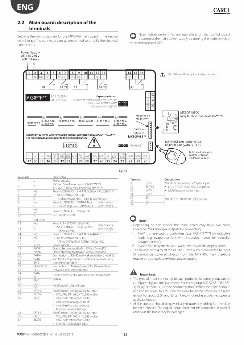
2.2 Main board: description of the
terminals
Below is the wiring diagram for the MPXPRO main board in the version
with 5 relays. The connectors are screen printed to simplify the electrical
connections.
Terminal Description30 GND Multifunction analogue/digital input
• NTC, PTC, PT1000, NTCL243 probe
• Multifunction digital input
32 S5/DI2
33 S4/DI1
34 GND
NTC/PTC/PT1000/NTCL243 probes35 S3
36 S2
37 S1
Note:• Depending on the model, the main board may have two open
collector/PWM analogue outputs for connecting:
1. PWM1: phase-cutting controllers (e.g. MCHRTF****) for inductive
loads (e.g. evaporator fans with inductive motors for optically-
isolated control);
2. PWM2: SSR relay for the anti-sweat heaters on the display cases;
• The devices with 4 to 20 mA or 0 to 10 Vdc output connected to input
S7 cannot be powered directly from the MPXPRO. They therefore
require an appropriate external power supply.
Important:• The type of input connected to each probe in the same group can be
confi gured by just one parameter. For each group 1(S1,S2,S3)-2(S4,S5)-
3(S6)-4(S7), there is just one parameter that defi nes the type of input,
and consequently this must be the same for all the probes in the same
group. For group 2, S4 and S5 can be confi gured as probes yet operate
as digital inputs.
• All the contacts should be galvanically insulated by adding further relays
for each contact. The digital inputs must not be connected in parallel,
otherwise the board may be damaged.
Note: before performing any operations on the control board,
disconnect the main power supply by turning the main switch in
the electrical panel OFF.
5VdcS7/DI4GND VLGNDDI5 GND
M.S.N.Tx/Rx
T.U.I.Tx/Rx
Tx/Rx+ Tx/Rx-S6/DI3
S5/DI2
AC 115-230 V
200 mA max
(*) = R2 and R4 only for 5 relays models
MX30P485**
6 (4) A N.O.
6 (4) A N.C.
6 (4) A N.O.
6 (4) A N.C.EN60730-1
R1
R1 R5
10 (10) A N.O.
R2
R2 (*)
10 (2) A N.O.
R3
R3
6 (4) A N.O.
R4
R4 (*)
R5
L N
8 9
NO NC C
10 11 12
NO C
13 14 15
NCNO C
16
36
S2S1 S3
35
17
18
12
VP
WM
1P
WM
2
19
32 4
NO NC CNL
6 7
CNO
51
37 33
S4/DI1GND
3234 30 2931 25 24262728 2223 2021
-10T50
MX30**H**
Power SupplyAC 115-230 V200 mA max
Expansion board:
- 0 to10 Vdc Analog output MX3OPA10**
- PWM driver MX3OPPWM**
- E2V driver MX3OPSTP**
PROG. KEY
CLOCK andSERIAL INT.
Mounted onMX30S*****
Maximum currents with removable vertical connectors cod. MX30***(C,I,O)**. For more details, please refer to the technical leaflets.
MXOPZKEYA0 (with rel. 2.x)IROPZKEYA0 (with rel. 1.x)
To be used only withcontrol switch off (no Power Supply)
MX3OP48500(only for slave models MX30S*****)
Fig. 2.a
Terminal Description1 L Power supply:
230 Vac, 50mA max. (mod. MX30***E**)
115 Vac, 100mA max. (mod. MX30***A**)2 N
3 NO Relay 1: EN60730-1: 6(4)A N.O.,6(4)A N.C. 2(2)A C.O.
UL: 6A res 240Vac N.O. / N.C.
1/2Hp 240Vac N.O. 1/6 Hp 120Vac N.O.
4 NC
5 C
6 NO Relay 2: EN60730-1: 10(10)A N.O.
UL: 10A res 1Hp 240/120 Vac N.O.
only models
with 5 relays7 C
8 NORelay 3: EN60730-1: 10(2)A N.O.
UL: 10A res 240Vac9 NC
10 C
11 Not used
12 NO Relay 4: EN60730-1: 6(4)A N.O.
UL: 6A res 240Vac; 1/2Hp 240Vac
1/6Hp 120Vac
only models
with 5 relays13 C
14 NO Relay 5: EN60730-1: 6(4)A N.O., 6(4)A N.C.
UL: 6A res 240Vac N.O. / N.C.
1/2Hp 240Vac N.O; 1/6Hp 120Vac N.O.
15 NC
16 C
17 +12V Power supply
18 PWM1 Open collector output PWM1: 12Vdc, 20mA MAX
19 PWM2 Open collector output PWM2: 12Vdc, 20mA MAX
20 Tx/Rx- Connection to RS485 network supervisory - CAREL
and Modbus® protocol - for Master controller only
(use shielded cable)
21 Tx/Rx+
22 GND
23 M.S.N Tx/Rx Connection to Master/Slave tLAN (Master Slave
Network). Use shielded cable.26 GND
24 Tx/RxtLAN connection for user terminals and remote
display25 VL
26 GND
26 GNDMultifunction digital input
27 DI5
28 DC 5 V Multifunction analogue/digital input
• NTC, PTC, PT1000, NTCL243 probe
• 0 to 5 Vdc ratiometric probe
• 0 to 10 Vdc analogue input
• 4 to 20 mA analogue input
• Multifunction digital input
29 S7/DI4
30 GND
28 DC 5 V Multifunction analogue/digital input
• NTC, PTC, PT1000, NTCL243 probe
• 0 to 5 Vdc ratiometric probe
• Multifunction digital input
30 GND
31 S6/DI3
13
ENG
MPXPRO - + 0300055EN rel. 1.4 - 29.09.2015
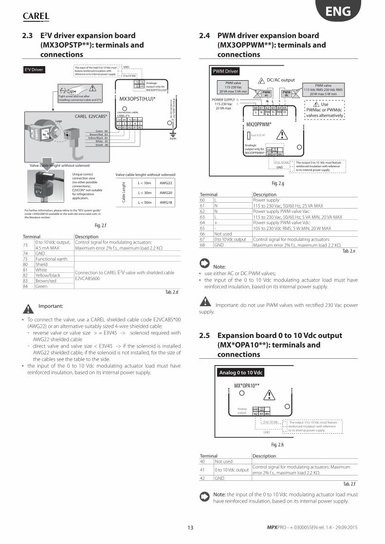
2.3 E2V driver expansion board
(MX3OPSTP**): terminals and
connections
75
GND
CAREL E2VCABS*
E2V Driver
MX3OPST(H,U)*
73 74
8182 8083841 3 2 4 5
10 Vdc GND
GR BR YE WH Shield
L < 10m AWG22
L < 30m AWG20
L < 50m AWG18
Valve cable lenght without solenoiddo
not
con
nect
toan
y “G
ND
” Ter
min
al
Earth
0 to10 Vdc
Analogic output only forMX3OPST(H,U)0*
The input of the load 0 to 10 Vdc mustfeature reinforced insulation with reference to its internal power supply
Tight screw and nut after installing connector/cable and E2V.
Unique correct connection view(no other possible connections).E2VCON* not suitable for refrigeration application.
Shield 80White 81
Yellow/Black 82 Brown/Red 83
Green 84
E2V Driver
connection cable CAREL E2V
For further information, please refere to the “EEV system guide”(code +030220810) available in the web site www.carel.com, in the literature section.
Cabl
e Le
nght
Valve cable lenght without solenoid
Fig. 2.f
Terminal Description
730 to 10 Vdc output,
4.5 mA MAX
Control signal for modulating actuators:
Maximum error 2% f.s., maximum load 2.2 KΩ
74 GND
75 Functional earth
80 Shield
Connection to CAREL E2V valve with shielded cable
E2VCABS600
81 White
82 Yellow/black
83 Brown/red
84 Green
Tab. 2.d
Important:
• To connect the valve, use a CAREL shielded cable code E2VCABS*00
(AWG22) or an alternative suitably sized 4-wire shielded cable:
- reverse valve or valve size > = E3V45 -> solenoid required with
AWG22 shielded cable
- direct valve and valve size < E3V45 -> if the solenoid is installed
AWG22 shielded cable, if the solenoid is not installed, for the size of
the cables see the table to the side.
• the input of the 0 to 10 Vdc modulating actuator load must have
reinforced insulation, based on its internal power supply.
2.4 PWM driver expansion board
(MX3OPPWM**): terminals and
connections
LN
PWMac
PWMdc
N L + –
GND
PWM Driver
MX2OPPWM*
64 6562 6360 61
6768 66
PWM+
DC-
PWMN
ACL
L N
10 VdcGND
0 to 10 Vdc
Fuse 0.25 AT
POWER SUPPLY115-230 Vac25 VA max
UsePWMac or PWMdc valves alternatively
DC/AC output
Analogic output only forMX2OPPWM0*
The output 0 to 10 Vdc must feature reinforced insulation with referenceto its internal power supply
PWM valve115-230 Vac
20 VA max 5 VA min
PWM valve115 Vdc RMS-230 Vdc RMS
20 W max 5 W min
Fig. 2.g
Terminal Description60 L Power supply:
115 to 230 Vac, 50/60 Hz, 25 VA MAX61 N
62 N Power supply PWM valve Vac:
115 to 230 Vac, 50/60 Hz, 5 VA MIN, 20 VA MAX63 L
64 + Power supply PWM valve Vdc:
105 to 230 Vdc RMS, 5 W MIN, 20 W MAX65 -
66 Not used
67 0 to 10 Vdc output Control signal for modulating actuators:
Maximum error 2% f.s., maximum load 2.2 KΩ.68 GND
Tab. 2.e
Note:• use either AC or DC PWM valves;
• the input of the 0 to 10 Vdc modulating actuator load must have
reinforced insulation, based on its internal power supply.
Important: do not use PWM valves with rectifi ed 230 Vac power
supply.
2.5 Expansion board 0 to 10 Vdc output
(MX*OPA10**): terminals and
connections
GND
MX*OPA10**
4142 40
10 VdcGNDAnalog
output
0 to 10 Vdc The output 0 to 10 Vdc must feature
reinforced insulation with reference
to its internal power supply.
Analog 0 to 10 Vdc
Fig. 2.h
Terminal Description40 Not used
41 0 to 10 Vdc outputControl signal for modulating actuators: Maximum
error 2% f.s., maximum load 2.2 KΩ.
42 GND
Tab. 2.f
Note: the input of the 0 to 10 Vdc modulating actuator load must
have reinforced insulation, based on its internal power supply.
14
ENG
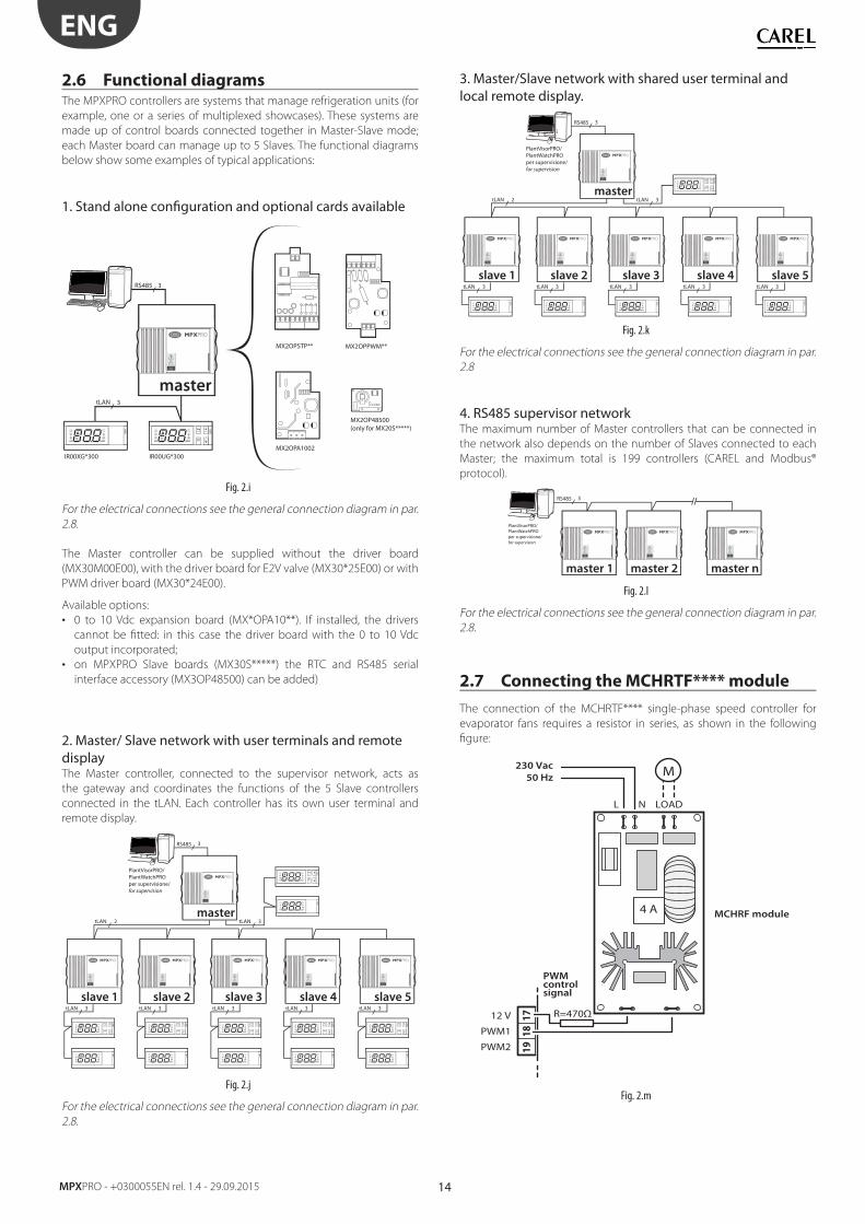
MPXPRO - +0300055EN rel. 1.4 - 29.09.2015
2.6 Functional diagramsThe MPXPRO controllers are systems that manage refrigeration units (for
example, one or a series of multiplexed showcases). These systems are
made up of control boards connected together in Master-Slave mode;
each Master board can manage up to 5 Slaves. The functional diagrams
below show some examples of typical applications:
1. Stand alone confi guration and optional cards available
AUXAUX
master
MX2OPSTP** MX2OPPWM**
MX2OPA1002
MX2OP48500(only for MX20S*****)
tLAN
IR00XG*300 IR00UG*300
3
RS485 3
MPXPRO
Highvoltage
Fig. 2.i
For the electrical connections see the general connection diagram in par.
2.8.
The Master controller can be supplied without the driver board
(MX30M00E00), with the driver board for E2V valve (MX30*25E00) or with
PWM driver board (MX30*24E00).
Available options:
• 0 to 10 Vdc expansion board (MX*OPA10**). If installed, the drivers
cannot be fi tted: in this case the driver board with the 0 to 10 Vdc
output incorporated;
• on MPXPRO Slave boards (MX30S*****) the RTC and RS485 serial
interface accessory (MX3OP48500) can be added)
2. Master/ Slave network with user terminals and remote displayThe Master controller, connected to the supervisor network, acts as
the gateway and coordinates the functions of the 5 Slave controllers
connected in the tLAN. Each controller has its own user terminal and
remote display.
AUX
AUX
AUX
AUX
slave 1
master
slave 2 slave 3 slave 4
AUX
AUX
AUX
AUX
AUX
AUX
tLAN 2
MPXPRO
Highvoltage
MPXPRO
Highvoltage
MPXPRO
Highvoltage
MPXPRO
Highvoltage
MPXPRO
Highvoltage
slave 5
AUX
AUX
MPXPRO
Highvoltage
RS485
PlantVisorPRO/PlantWatchPRO per supervisione/for supervision
tLAN 3
3
tLAN 3 tLAN 3 tLAN 3 tLAN 3 tLAN 3
Fig. 2.j
For the electrical connections see the general connection diagram in par.
2.8.
3. Master/Slave network with shared user terminal and local remote display.
AUXAUXAUXAUXAUX
slave 1
master
slave 2 slave 3 slave 4
tLAN 2
MPXPRO
Highvoltage
MPXPRO
Highvoltage
MPXPRO
Highvoltage
MPXPRO
Highvoltage
MPXPRO
Highvoltage
slave 5
AUX
MPXPRO
Highvoltage
RS485
PlantVisorPRO/PlantWatchPRO per supervisione/for supervision
tLAN 3
3
tLAN 3 tLAN 3 tLAN 3 tLAN 3 tLAN 3
Fig. 2.k
For the electrical connections see the general connection diagram in par.
2.8
4. RS485 supervisor networkThe maximum number of Master controllers that can be connected in
the network also depends on the number of Slaves connected to each
Master; the maximum total is 199 controllers (CAREL and Modbus®
protocol).
MPXPRO
Highvoltage
MPXPRO
Highvoltage
MPXPRO
Highvoltage
PlantVisorPRO/PlantWatchPRO per supervisione/for supervision
master 1 master 2 master n
RS485 3
Fig. 2.l
For the electrical connections see the general connection diagram in par.
2.8.
2.7 Connecting the MCHRTF**** module
The connection of the MCHRTF**** single-phase speed controller for
evaporator fans requires a resistor in series, as shown in the following
fi gure:
4 A
R=470Ω12 V
PWMcontrolsignal
230 Vac
50 Hz
MCHRF module
PWM1
PWM2
L N
M
LOAD
1918
17
Fig. 2.m
15
ENG
MPXPRO - + 0300055EN rel. 1.4 - 29.09.2015
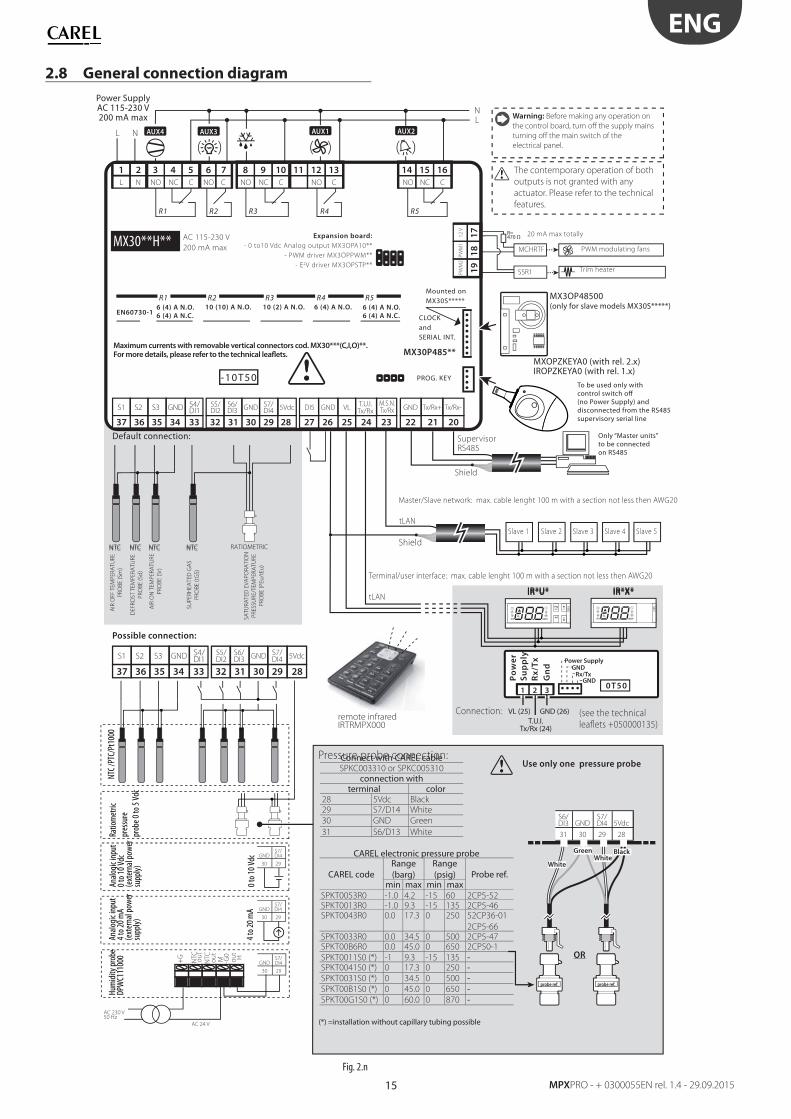
2.8 General connection diagram
5VdcS7/DI4GND VL
VL (25)
GND
GND (26)
DI5 GNDM.S.N.Tx/Rx
T.U.I.Tx/Rx
T.U.I.Tx/Rx (24)
Tx/Rx+ Tx/Rx-S6/DI3
S5/DI2
LN
AC 115-230 V
200 mA max LOAD 1LOAD 2
AUX3 AUX1 AUX2
( ( ( (( (
MX30P485**
6 (4) A N.O.
6 (4) A N.C.
6 (4) A N.O.
6 (4) A N.C.EN60730-1
R1
R1 R5
10 (10) A N.O.
R2
R2
10 (2) A N.O.
R3
R3
6 (4) A N.O.
R4
R4
R5
L N
8 9
NO NC C
10 11 12
NO C
13 14 15
NCNO C
16
36
S2S1 S3
35
17
18
12
VP
WM1
PW
M2
19
32 4
NO NC CNL
6 7
CNO
51
37 33
S4/DI1GND
3234 30 2931 25 24262728 2223 2021
-10T50
MX30**H**
AUX AUX
IR*U* IR*X*
2930
S7/DI4GND
2930
S7/DI4GND
28293031
5VdcS7/DI4GND
S6/DI3
NTC NTC NTC NTC
1 2 30T50
Po
we
r
Su
pp
ly
Rx
/Tx
Gn
d
36
S2S1 S3
3537 33
S4/DI1GND
34
5VdcS7/DI4GNDS6/
DI3S5/DI2
32 30 2931 28
Power Supply
Rx/TxGND
GND
SSR1
MCHRTF
R=470 Ω
2930
S7/DI4GNDN
TCout
+G
NTCout
M
-G0
out
H
AC 24 V
AC 230 V50 Hz
AUX4
Power SupplyAC 115-230 V200 mA max
PWM modulating fans
20 mA max totally
Trim heater
Expansion board:
- 0 to10 Vdc Analog output MX3OPA10**
- PWM driver MX3OPPWM**
- E2V driver MX3OPSTP**
PROG. KEY
CLOCKandSERIAL INT.
Mounted onMX30S*****
Maximum currents with removable vertical connectors cod. MX30***(C,I,O)**. For more details, please refer to the technical leaflets.
To be used only withcontrol switch off (no Power Supply) anddisconnected from the RS485 supervisory serial line
MX3OP48500(only for slave models MX30S*****)
Only “Master units” to be connected on RS485
Master/Slave network: max. cable lenght 100 m with a section not less then AWG20
SupervisorRS485
Terminal/user interface: max. cable lenght 100 m with a section not less then AWG20
IR*U* IR*X*
Slave 1 Slave 2 Slave 4 Slave 5
Ratio
met
ric
pres
sure
prob
e 0
to 5
Vdc
Anal
ogic
inpu
t0
to 1
0 Vd
c(e
xter
nal p
ower
supp
ly)
0 to
10
Vdc
NTC
/PTC
/Pt1
000
AIR
OFF
TE
MP
ER
AT
UR
E
PR
OB
E (
Sm
)
DEF
RO
ST
TE
MP
ER
AT
UR
E
PR
OB
E (
Sd
)
AIR
ON
TE
MP
ER
AT
UR
E
PR
OB
E (
Sr)
SU
PE
RH
EA
TED
GA
S
PR
OB
E (tG
S)
SA
TU
RA
TED
EV
AP
OR
AT
ION
PR
ES
SU
RE
/TE
MP
ER
AT
UR
E
PR
OB
E (
PEu
/tEu
)
Anal
ogic
inpu
t4
to 2
0 m
A(e
xter
nal p
ower
supp
ly)
4 to
20
mA
Slave 3
Pressure probe connection:
BlackWhite
Green
White
Use only one pressure probe
OR
probe ref. probe ref.
NTC NTC NTC NTC RATIOMETRIC
Shield
Shield
Default connection:
Possible connection:
The contemporary operation of both
outputs is not granted with any
actuator. Please refer to the technical
features.
Hum
idity
pro
beDP
WC1
1100
0
remote infraredIRTRMPX000
Warning: Before making any operation on
the control board, turn off the supply mains
turning off the main switch of the
electrical panel.
MXOPZKEYA0 (with rel. 2.x)IROPZKEYA0 (with rel. 1.x)
Connection: (see the technical
leaflets +050000135)
tLAN
tLAN
Fig. 2.n
CAREL electronic pressure probe
CAREL codeRange(barg)
Range(psig) Probe ref.
min max min maxSPKT0053R0 -1.0 4.2 -15 60 2CP5-52SPKT0013R0 -1.0 9.3 -15 135 2CP5-46SPKT0043R0 0.0 17.3 0 250 52CP36-01
2CP5-66SPKT0033R0 0.0 34.5 0 500 2CP5-47SPKT00B6R0 0.0 45.0 0 650 2CP50-1
SPKT0011S0 (*) -1 9.3 -15 135 -SPKT0041S0 (*) 0 17.3 0 250 -SPKT0031S0 (*) 0 34.5 0 500 -SPKT00B1S0 (*) 0 45.0 0 650 -SPKT00G1S0 (*) 0 60.0 0 870 -
Connect with CAREL cableSPKC003310 or SPKC005310
connection withterminal color
28 5Vdc Black29 S7/D14 White
30 GND Green
31 S6/D13 White
(*) =installation without capillary tubing possible
16
ENG
MPXPRO - +0300055EN rel. 1.4 - 29.09.2015
2.9 Installation
For installation proceed as follows, with reference to the wiring diagrams:
1. before performing any operations on the control board, disconnect
the main power supply by turning the main switch in the electrical
panel OFF. Then remove the plastic side cover and/or the covers to
make the electrical connections;
2. avoid touching the control board, as electrostatic discharges may
damage the electronic components;
3. the index of protection required for the application must be ensured
by the manufacturer of the display case or by suitable assembly of
the controller;
4. connect any digital inputs, Lmax=10m;
5. connect the power cable to the valve motor: to fi nd the section or
cable lenght, see “terminals and connections” section.
6. connect the actuators: the actuators should only be connected after
having programmed the controller. Carefully evaluate the maximum
ratings of the relay outputs as indicated in “Technical specifi cations”;
7. program the controller: see the chapter “User interface”.
8. for the tLAN connection of the Master/Slave network and user
interfaces, use shielded cable and make sure:
• the maximum distance between a controller and its user terminal/
remote display is 100 m (with section of cable not less than AWG22);
• the maximum distance between the controllers and the maximum
length of the cable between one controller and another is 100 m
(with section of cable not less than AWG22).
Important: avoid installing the controllers in environments with
the following characteristics:
• relative humidity greater than the 90% or condensing;
• strong vibrations or knocks;
• exposure to continuous water sprays;
• exposure to aggressive and polluting atmospheres (e.g.: sulphur
and ammonia fumes, saline mist, smoke) to avoid corrosion and/or
oxidation;
• strong magnetic and/or radio frequency interference (avoid installing
the controllers near transmitting antennae);
• exposure of the controllers to direct sunlight and to the elements in
general.
Important: when connecting the controllers, the following
warnings must be observed:
• incorrect connection to the power supply may seriously damage the
controller;
• use cable ends suitable for the corresponding terminals. Loosen each
screw and insert the cable ends, then tighten the screws and lightly
tug the cables to check correct tightness;
• separate as much as possible the probe and digital input cables from
the power cables to the loads so as to avoid possible electromagnetic
disturbance. Never lay power cables and probe cables in the same
conduits (including those in the electrical panels);
• avoid installing the probe cables in the immediate vicinity of power
devices (contactors, circuit breakers, etc.). Reduce the path of the
probe cables as much as possible and avoid enclosing power devices.
Note: when connecting the RS485 serial network:
• connect the shield to the GND terminals on all controllers;
• do not connect the shield to the earth on the electrical panel;
• use a twisted pair shielded cable (e.g. Belden 8762 – AWG 20 or BELDEN
8761-AWG 22);
• connect a 120 Ω terminal resistor between the Tx/Rx+ and Tx/Rx-
terminals on the last MPXPRO controller.
2.10 Programming key (copy set-up)
Important: the key must be used with the controller off and with
the RS485 serial line disconnected from the MPXPRO. The MXOPZKEYA0/
IROPZKEYA0 programming key is used to copy the complete set of
MPXPRO parameters. The key must be plugged into the connector (4 pin
AMP) on the controllers (with the controller powered down).
Note: MXOPZKEYA0 can only be used on MPXPRO with fi rmware
versions >= 2.1 (with max. 6 sets of parameters); IROPZKEYA0 can only be
used on MPXPRO with fi rmware versions <=1.2 (with max. 2 sets of
parameters).
The fi rmware version of the MPXPRO can be identifi ed as follows:
1. on the label applied to the rear of the instrument. The second part of
the revision number represents the fi rmware version (e.g. Rev. 1.326
means fi rmware revision 2.6). This info is valid only if the MPXPRO has
never been updated by the user;
2. on the terminal display. When powering up the MPXPRO, the terminal
displays the fi rmware revision (e.g. r 2.6) for a couple of seconds;
3. using the VPM or from the supervisor (Integer variable 11: Firmware
release). Offi cial versions available are 1.0, 1.1, 1.2 - 2.1, 2.2, 2.6, 2.8.
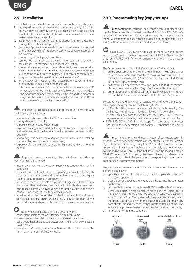
By setting the two dipswitches (accessible when removing the cover),
the programming key can run the following functions:
• UPLOAD. Load the parameters from a controller to the key (see Fig. 2.p):
the key acquires all the parameters available on the controller;
• DOWNLOAD. Copy from the key to a controller (see Fig.2.q): the key
only transfers the operating parameters to the connected controller;
• EXTENDED DOWNLOAD. Extended copy from the key to a controller
(see Fig.2.r): the key transfers all the parameters (operating and unit) to
the connected controller.
Important: the copy and extended copy of parameters can only
be performed between compatible instruments, that is, with the same or
higher fi rmware revision (e.g. copy from 2.2 to 2.4, but not vice-versa).
Version 4.0 will only be compatible with version 3.3, so a confi guration
corresponding to version 3.3 (and not lower) can be loaded onto an
MPXPRO version 4.0. If copying between diff erent hardware, it is
recommended to check the parameters corresponding to the specifi c
confi guration (e.g.: valve parameters).
The UPLOAD, DOWNLOAD and EXTENDED DOWNLOAD functions are
performed as follows:
a. open the rear cover of the key and set the two dipswitches based on
the desired operation;
b. close the cover, power up the key and plug the key into the connector
on the controller;
c. press and hold the button until the red LED fl ashed briefl y, after around
5-10 s (the button can still be held). When the button is released, the
LED stays on red until the end of the operation, which may last up to
a maximum of 45 sec. The operation is completed successfully when
the green LED comes on. With the button released, the green LED
goes off after around 2 seconds. Other signals or fl ashing of the LEDs
indicate that problems have occurred: see the corresponding table;
d. remove the key from the controller.
upload download extended download
Fig. 2.o Fig. 2.p Fig. 2.q
17
ENG
MPXPRO - + 0300055EN rel. 1.4 - 29.09.2015
LED signal Cause Meaning Solution
Orange fl ashingController not
compatible
The parameters
cannot be copied
due to incom-
patibility of the
fi rmware versions
Check compatibility of
the fi rmware versions
(see notes above)
Red fl ashingIncorrect use of
the key
The button on
the key has been
released too early
Repeat the procedure
following the instruc-
tions in point c.
Orange steady Data copy error
The data on the
controller or the
key may be corrupt
Repeat the operation
or contact service
Off Key not powered
or fault--
Check that the key is
powered or contact
service
Tab. 2.g
The key can be programmed not only from the MPXPRO controller,
but also directly from a PC, using the special USB/I2C converter
(IRPOPZPRGO0) and the VPM program. Using this connection, the PC can
completely program the key. Specifi cally, the following operations are
possible: set the values of the parameters (both unit and operating), set
the visibility and upload attribute, write and read the parameters to/from
a fi le, and check the parameters.
2.11 Commissioning tool (VPM- Visual
Parameter Manager)MPXPRO can communicate directly with a PC using the “commissioning”
port. This connection can be used to program and check the operation
of an MPXPRO controller from the PC when installing and fi rst starting the
system. The commissioning connection can be used to:
• set value, visibility and download attributes of all the parameters from
Master to Slave, including unit parameters;
• completely program a key;
• at start-up, monitor and manually control all the inputs/outputs;
• update the fi rmware.
A PC can access the commissioning connection via the special port
available on some user terminals code IR00UGC300 and remote display
code IR00XGC300 or in supervisory RS485 network. The commissioning
software can also be used to program the key. Further information on
the operation of the commissioning software is available in the online
manual for the VPM program, downloadable from http://ksa.carel.com.
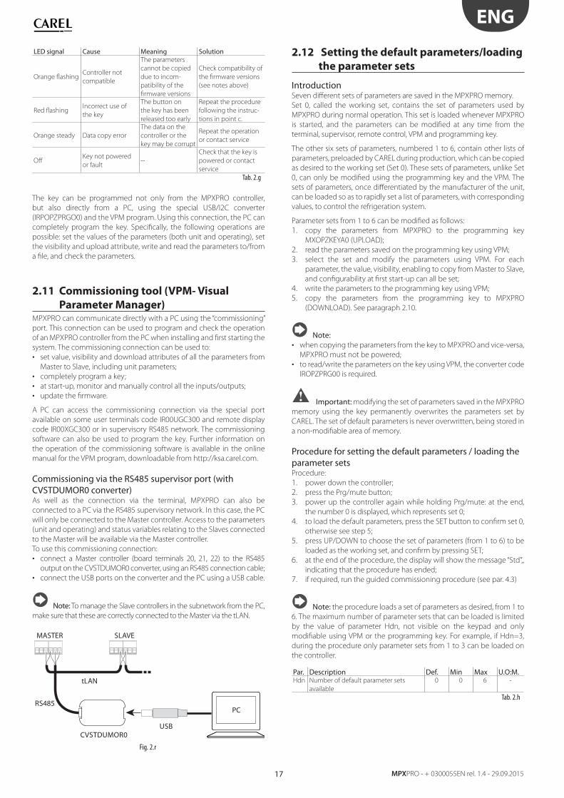
Commissioning via the RS485 supervisor port (with CVSTDUMOR0 converter)As well as the connection via the terminal, MPXPRO can also be
connected to a PC via the RS485 supervisory network. In this case, the PC
will only be connected to the Master controller. Access to the parameters
(unit and operating) and status variables relating to the Slaves connected
to the Master will be available via the Master controller.
To use this commissioning connection:
• connect a Master controller (board terminals 20, 21, 22) to the RS485
output on the CVSTDUMOR0 converter, using an RS485 connection cable;
• connect the USB ports on the converter and the PC using a USB cable.
Note: To manage the Slave controllers in the subnetwork from the PC,
make sure that these are correctly connected to the Master via the tLAN.
MASTER SLAVE
USB
RS485
CVSTDUMOR0
tLAN
PC
Fig. 2.r
2.12 Setting the default parameters/loading
the parameter sets
Introduction Seven diff erent sets of parameters are saved in the MPXPRO memory.
Set 0, called the working set, contains the set of parameters used by
MPXPRO during normal operation. This set is loaded whenever MPXPRO
is started, and the parameters can be modifi ed at any time from the
terminal, supervisor, remote control, VPM and programming key.
The other six sets of parameters, numbered 1 to 6, contain other lists of
parameters, preloaded by CAREL during production, which can be copied
as desired to the working set (Set 0). These sets of parameters, unlike Set
0, can only be modifi ed using the programming key and the VPM. The
sets of parameters, once diff erentiated by the manufacturer of the unit,
can be loaded so as to rapidly set a list of parameters, with corresponding
values, to control the refrigeration system.
Parameter sets from 1 to 6 can be modifi ed as follows:
1. copy the parameters from MPXPRO to the programming key
MXOPZKEYA0 (UPLOAD);
2. read the parameters saved on the programming key using VPM;
3. select the set and modify the parameters using VPM. For each
parameter, the value, visibility, enabling to copy from Master to Slave,
and confi gurability at fi rst start-up can all be set;
4. write the parameters to the programming key using VPM;
5. copy the parameters from the programming key to MPXPRO
(DOWNLOAD). See paragraph 2.10.
Note: • when copying the parameters from the key to MPXPRO and vice-versa,
MPXPRO must not be powered;
• to read/write the parameters on the key using VPM, the converter code
IROPZPRG00 is required.
Important: modifying the set of parameters saved in the MPXPRO
memory using the key permanently overwrites the parameters set by
CAREL. The set of default parameters is never overwritten, being stored in
a non-modifi able area of memory.
Procedure for setting the default parameters / loading the parameter setsProcedure:
1. power down the controller;
2. press the Prg/mute button;
3. power up the controller again while holding Prg/mute: at the end,
the number 0 is displayed, which represents set 0;
4. to load the default parameters, press the SET button to confi rm set 0,
otherwise see step 5;
5. press UP/DOWN to choose the set of parameters (from 1 to 6) to be
loaded as the working set, and confi rm by pressing SET;
6. at the end of the procedure, the display will show the message “Std”,,
indicating that the procedure has ended;
7. if required, run the guided commissioning procedure (see par. 4.3)
Note: the procedure loads a set of parameters as desired, from 1 to
6. The maximum number of parameter sets that can be loaded is limited
by the value of parameter Hdn, not visible on the keypad and only
modifi able using VPM or the programming key. For example, if Hdn=3,
during the procedure only parameter sets from 1 to 3 can be loaded on
the controller.
Par. Description Def. Min Max U.O:M.Hdn Number of default parameter sets
available
0 0 6 -
Tab. 2.h
18
ENG
MPXPRO - +0300055EN rel. 1.4 - 29.09.2015
3. USER INTERFACE
The front panel of the user terminal (IR00UG****) includes the display and
the keypad, featuring 4 buttons that, pressed alone or in combination, are
used to program the controller. The remote display (IR00XG****) is only
used to show the values of system variables.
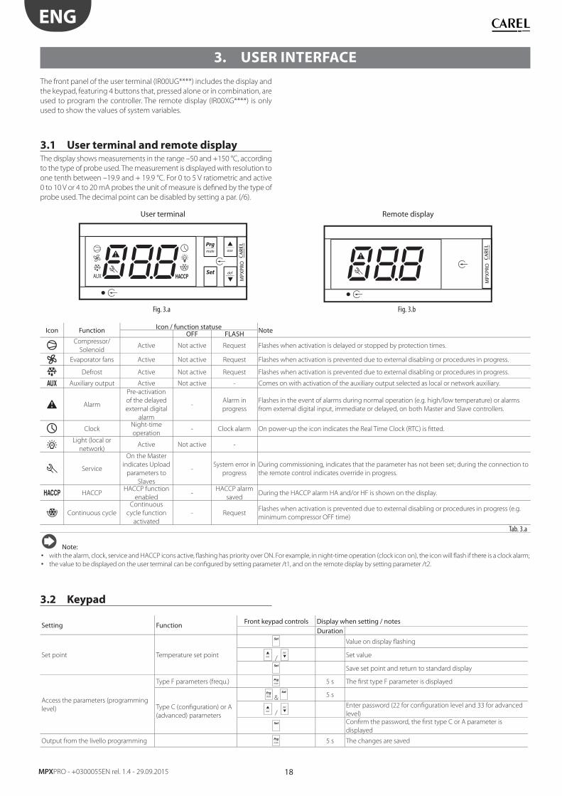
3.1 User terminal and remote displayThe display shows measurements in the range –50 and +150 °C, according
to the type of probe used. The measurement is displayed with resolution to
one tenth between –19.9 and + 19.9 °C. For 0 to 5 V ratiometric and active
0 to 10 V or 4 to 20 mA probes the unit of measure is defi ned by the type of
probe used. The decimal point can be disabled by setting a par. (/6).
User terminal Remote display
AUX
MPX
PRO
MPX
PRO
Fig. 3.a Fig. 3.b
Icon Function Icon / function statuse NoteOFF FLASHCompressor/
SolenoidActive Not active Request Flashes when activation is delayed or stopped by protection times.
Evaporator fans Active Not active Request Flashes when activation is prevented due to external disabling or procedures in progress.
Defrost Active Not active Request Flashes when activation is prevented due to external disabling or procedures in progress.
Auxiliary output Active Not active - Comes on with activation of the auxiliary output selected as local or network auxiliary.
Alarm
Pre-activation
of the delayed
external digital
alarm
-Alarm in
progress
Flashes in the event of alarms during normal operation (e.g. high/low temperature) or alarms
from external digital input, immediate or delayed, on both Master and Slave controllers.
Clock Night-time
operation- Clock alarm On power-up the icon indicates the Real Time Clock (RTC) is fi tted.
Light (local or
network)Active Not active -
Service
On the Master
indicates Upload
parameters to
Slaves
-System error in
progress
During commissioning, indicates that the parameter has not been set; during the connection to
the remote control indicates override in progress.
HACCPHACCP function
enabled-
HACCP alarm
savedDuring the HACCP alarm HA and/or HF is shown on the display.
Continuous cycle
Continuous
cycle function
activated
- Request Flashes when activation is prevented due to external disabling or procedures in progress (e.g.
minimum compressor OFF time)
Tab. 3.a
Note:• with the alarm, clock, service and HACCP icons active, fl ashing has priority over ON. For example, in night-time operation (clock icon on), the icon will fl ash if there is a clock alarm;
• the value to be displayed on the user terminal can be confi gured by setting parameter /t1, and on the remote display by setting parameter /t2.
3.2 Keypad
Setting Function Front keypad controls Display when setting / notesDuration
Set point Temperature set point
Value on display fl ashing
/ Set value
Save set point and return to standard display
Access the parameters (programming
level)
Type F parameters (frequ.) 5 s The fi rst type F parameter is displayed
Type C (confi guration) or A
(advanced) parameters
& 5 s
/ Enter password (22 for confi guration level and 33 for advanced
level)
Confi rm the password, the fi rst type C or A parameter is
displayed
Output from the livello programming 5 s The changes are saved
19
ENG
MPXPRO - + 0300055EN rel. 1.4 - 29.09.2015
Setting Function Front keypad controls Display when setting / notesDuration
Defrost
Local defrost
5 s dFb : activate defrost dFE : deactivate defrost
Multiplexed defrost (Master
only) & 5 s dFb : activate defrost dFE : deactivate defrost
Auxiliary functionsContinuous cycle
/ 5 s
ccb : activate continuous cycle (see paragraph 6.6)
ccE : deactivate continuous cycle
AUX output Activate/deactivate auxiliary output
Network functions (only for Master)
Copy parameters from
Master to Slave
& 5 s
/ Enter password (default 66)
See paragraph 3.6 : “Copy parameters from Master to Slave”
Display network unit status
from Master & & Select Slave: see paragraph 3.5 : “Display Slave controller status
from Master terminal”
Set the default parameters (restore
parameters)Set default parameters (*) on power-up If 0 is displayed press set to continue
Alarms
Display alarm log
& 5 s
& Enter password (default 44)
See paragraph 9.3: “Display alarm log”
Manual alarm reset &
5 s “rES” indicates the alarm has been reset
Mute buzzer and disable
alarm relay
HACCP HACCP menu &
See par. 9.4 “HACCP alarms and display”
Tab. 3.b
(*) The default parameters, or any of the sets of parameters loaded inside MPXPRO, only have eff ect on the parameters visible from the user terminal, based on the list of
parameters. The parameters that are not visible on the user terminal are not aff ected by this procedure.
3.3 ProgrammingThe parameters can be modifi ed using the front keypad. Access diff ers
according to the type: Frequent (F), confi guration (C) and advanced (A)
parameters. The type of parameter is indicated in the table parameters. Access
to the confi guration and advanced parameters is protected by a password
that prevents unwanted modifi cations by unauthorised people. The password
for the advanced parameters also allows access to all the control parameters;
this operation must only be performed by qualifi ed personnel.
Select network unit (Master)If using a user terminal connected directly to the Master controller, this
function can be used to choose the desired unit. After having identifi ed
the required setting (e.g. edit parameters, access the alarm log,...), then:
• scroll the list of Slave units available pressing UP or DOWN;
• press Set to select the desired unit:
uM u1 u2 u3 u4 u5Master Slave 1 Slave 2 Slave 3 Slave 4 Slave 5
Tab. 3.c
(uxo indicates that controller x is OFFLINE);
• to return to the normal display press Prg/mute.
The controller will in any case return to the normal display after a timeout
of around 1 minute.
MP
XPR
O
Fig. 3.c
MP
XPR
O
Fig. 3.d
Note: this specifi c procedure can be managed from the Master
controller only, if the user terminal is connected to a Slave controller the
procedure is limited to that Slave only.
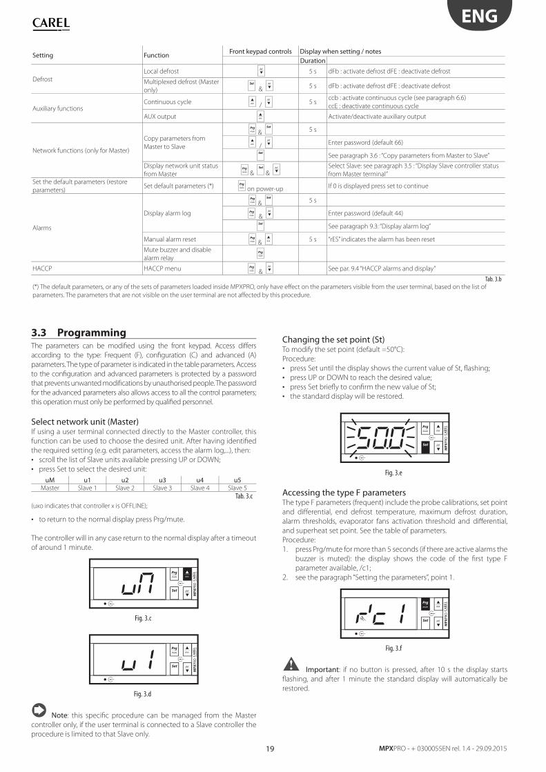
Changing the set point (St)To modify the set point (default =50°C):
Procedure:
• press Set until the display shows the current value of St, fl ashing;
• press UP or DOWN to reach the desired value;
• press Set briefl y to confi rm the new value of St;
• the standard display will be restored.
MP
XPR
O
Fig. 3.e
Accessing the type F parametersThe type F parameters (frequent) include the probe calibrations, set point
and diff erential, end defrost temperature, maximum defrost duration,
alarm thresholds, evaporator fans activation threshold and diff erential,
and superheat set point. See the table of parameters.
Procedure:
1. press Prg/mute for more than 5 seconds (if there are active alarms the
buzzer is muted): the display shows the code of the fi rst type F
parameter available, /c1;
2. see the paragraph “Setting the parameters”, point 1.
MP
XPR
O
Fig. 3.f
Important: if no button is pressed, after 10 s the display starts
fl ashing, and after 1 minute the standard display will automatically be
restored.
20
ENG
MPXPRO - +0300055EN rel. 1.4 - 29.09.2015
Accessing the type C parametersThe type C parameters (confi guration) include the choice of variable displayed
on the user terminal, assignment of the of the outlet, intake and defrost
functions to the probes, confi guration of the digital inputs, behaviour of the
evaporator fans during defrost, confi guration of the Master/Slave network,
and defrost time bands. See the table of parameters.
Procedure:
1. press Prg/mute and Set together for more than 5 seconds (if there are
active alarms the buzzer is muted): the display shows the number
0 fl ashing;
2. press UP or DOWN and enter the PASSWORD: 22. Confi rm by selecting
Set;
3. the fi rst modifi able type C parameter is displayed, /4;
4. see the paragraph “Setting the parameters”, point 1.
Accessing the type A parametersThe type A parameters (advanced) include the choice of the type of
probe (NTC, PTC, PT1000, NTC L243) for each of the four groups of probes,
assignment of the superheat control, ambient temperature and humidity
and glass temperature probes, compressor protection parameters, the
parameters that defi ne the defrost algorithm used (Sequential stops,
Running time, Power defrost, Skip defrost, etc.), maximum and minimum
evaporator fan speed, the integration times and delays for the superheat
protection functions, and the parameters for displaying the normal and
HACCP alarm queue.
1. press Prg/mute and Set together for more than 5 seconds (if there
are active alarms the buzzer is muted): the display shows the number
0 fl ashing;
2. press UP or DOWN and enter the PASSWORD: 33. Confi rm by selecting
Set;
3. the fi rst modifi able type A parameter is displayed, /2;
4. see the paragraph “Setting the parameters”, point 1.
Important:
• with this procedure, available starting from fi rmware version 2.x, all the
controller parameters can be accessed;
• the type of parameters (F= frequent, C= confi guration, A= advanced,)
and the related password can be modifi ed using the VPM program.
Setting the parametersOnce having accessed the desired level of parameters (F, C or A):
1. press UP or DOWN until reaching the desired parameter: when scrolling, an
icon appears on the display representing the category the parameter
belongs to (see the table below and the table of parameters);
2. or: press Prg/mute to display the menu of parameter categories. See
the table of parameters at the end of manual for further details on
the categories. Press UP/DOWN until reaching the desired category
of parameters and press Set: the list of parameters in the selected
category is displayed;
Category Icon Category IconProbes Electronic valve
Control Confi guration
Compressor Alarm log
Defrost HACCP
Alarm RTC
Evaporator fans
Tab. 3.d
3. press UP or DOWN until reaching the desired parameter;
4. press Set to display the associated value;
5. increase or decrease the value of the parameter using UP or DOWN;
6. press Set to temporarily save the new value and return to display the
parameter code;
7. if the parameter has sub-parameters, after having selected the parameter,
press Set again to enter the sub-menu, use the UP or DOWN button
to scroll between the sub-parameters, which can be modifi ed like a
normal parameter. Press Set again to temporarily save the values and
Prg/mute return to the higher level menu;
8. repeat steps from 3) to 7) to modify other parameters;
9. to permanently save the new values assigned to the parameters Prg/
mute for 5 seconds. This exits the parameter setting procedure.
Note:
• all the changes made to the parameters, temporarily stored in the RAM,
can be cancelled, returning to the standard display by not pressing any
button for 60 seconds. The values of the clock parameters, however,
are saved when entered.
• if the controller is powered down before pressing Prg/mute, all the
changes made to the parameters will be lost
• in the two parameter setting procedures (C and A), the new values are
only saved after having pressed Prg/mute for 5 seconds. When setting
the set point, the new value is saved after confi rming with Set.
3.4 Ex.: setting current date/time and day/
night time bands
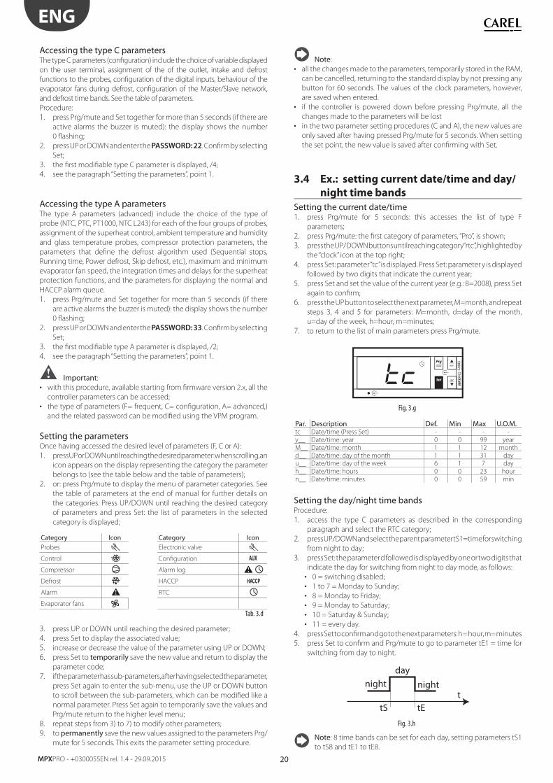
Setting the current date/time 1. press Prg/mute for 5 seconds: this accesses the list of type F
parameters;
2. press Prg/mute: the fi rst category of parameters, “Pro”, is shown;
3. press the UP/DOWN buttons until reaching category “rtc”, highlighted by
the “clock” icon at the top right;
4. press Set: parameter “tc” is displayed. Press Set: parameter y is displayed
followed by two digits that indicate the current year;
5. press Set and set the value of the current year (e.g.: 8=2008), press Set
again to confi rm;
6. press the UP button to select the next parameter, M=month, and repeat
steps 3, 4 and 5 for parameters: M=month, d=day of the month,
u=day of the week, h=hour, m=minutes;
7. to return to the list of main parameters press Prg/mute.
MP
XPR
O
Fig. 3.g
Par. Description Def. Min Max U.O.M.tc Date/time (Press Set) - - - -
y__ Date/time: year 0 0 99 year
M__ Date/time: month 1 1 12 month
d__ Date/time: day of the month 1 1 31 day
u__ Date/time: day of the week 6 1 7 day
h__ Date/time: hours 0 0 23 hour
n__ Date/time: minutes 0 0 59 min
Setting the day/night time bandsProcedure:
1. access the type C parameters as described in the corresponding
paragraph and select the RTC category;
2. press UP/DOWN and select the parent parameter tS1=time for switching
from night to day;
3. press Set: the parameter d followed is displayed by one or two digits that
indicate the day for switching from night to day mode, as follows:
• 0 = switching disabled;
• 1 to 7 = Monday to Sunday;
• 8 = Monday to Friday;
• 9 = Monday to Saturday;
• 10 = Saturday & Sunday;
• 11 = every day.
4. press Set to confi rm and go to the next parameters: h = hour, m= minutes
5. press Set to confi rm and Prg/mute to go to parameter tE1 = time for
switching from day to night.
tnight
tS
night
day
tE
Fig. 3.h
Note: 8 time bands can be set for each day, setting parameters tS1
to tS8 and tE1 to tE8.
21
ENG
MPXPRO - + 0300055EN rel. 1.4 - 29.09.2015
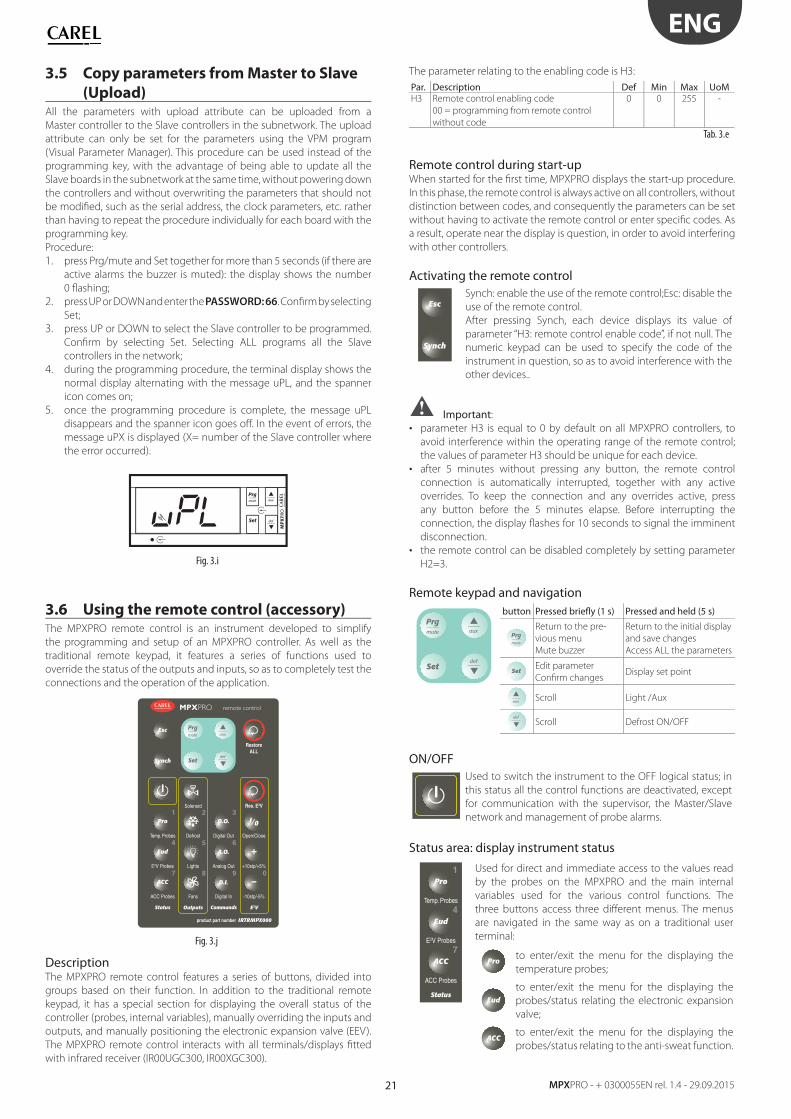
3.5 Copy parameters from Master to Slave
(Upload)All the parameters with upload attribute can be uploaded from a
Master controller to the Slave controllers in the subnetwork. The upload
attribute can only be set for the parameters using the VPM program
(Visual Parameter Manager). This procedure can be used instead of the
programming key, with the advantage of being able to update all the
Slave boards in the subnetwork at the same time, without powering down
the controllers and without overwriting the parameters that should not
be modifi ed, such as the serial address, the clock parameters, etc. rather
than having to repeat the procedure individually for each board with the
programming key.
Procedure:
1. press Prg/mute and Set together for more than 5 seconds (if there are
active alarms the buzzer is muted): the display shows the number
0 fl ashing;
2. press UP or DOWN and enter the PASSWORD: 66. Confi rm by selecting
Set;
3. press UP or DOWN to select the Slave controller to be programmed.
Confi rm by selecting Set. Selecting ALL programs all the Slave
controllers in the network;
4. during the programming procedure, the terminal display shows the
normal display alternating with the message uPL, and the spanner
icon comes on;
5. once the programming procedure is complete, the message uPL
disappears and the spanner icon goes off . In the event of errors, the
message uPX is displayed (X= number of the Slave controller where
the error occurred).
MP
XPR
O
Fig. 3.i
3.6 Using the remote control (accessory)The MPXPRO remote control is an instrument developed to simplify
the programming and setup of an MPXPRO controller. As well as the
traditional remote keypad, it features a series of functions used to
override the status of the outputs and inputs, so as to completely test the
connections and the operation of the application.
Set
remote control
Esc
Pro D.O.
A.O.Eud
Synch
Status Commands
Temp. Probes Digital Out
E2V Probes Analog Out
RestoreALL
Res. E2V
D.I.ACC
ACC Probes Digital In
product part number IRTRMPX000
Lights
Solenoid
Outputs
Defrost
Fans
3
4 5 6
1 2
7 8 9 0
+
I/0
E2V
Open/Close
+10stp/+5%
-10stp/-5%
Fig. 3.j
Description The MPXPRO remote control features a series of buttons, divided into
groups based on their function. In addition to the traditional remote
keypad, it has a special section for displaying the overall status of the
controller (probes, internal variables), manually overriding the inputs and
outputs, and manually positioning the electronic expansion valve (EEV).
The MPXPRO remote control interacts with all terminals/displays fi tted
with infrared receiver (IR00UGC300, IR00XGC300).
The parameter relating to the enabling code is H3:
Par. Description Def Min Max UoMH3 Remote control enabling code
00 = programming from remote control
without code
0 0 255 -
Tab. 3.e
Remote control during start-upWhen started for the fi rst time, MPXPRO displays the start-up procedure.
In this phase, the remote control is always active on all controllers, without
distinction between codes, and consequently the parameters can be set
without having to activate the remote control or enter specifi c codes. As
a result, operate near the display is question, in order to avoid interfering
with other controllers.
Activating the remote control
Esc
Synch
Synch: enable the use of the remote control;Esc: disable the
use of the remote control.
After pressing Synch, each device displays its value of
parameter “H3: remote control enable code”, if not null. The
numeric keypad can be used to specify the code of the
instrument in question, so as to avoid interference with the
other devices..
Important:
• parameter H3 is equal to 0 by default on all MPXPRO controllers, to
avoid interference within the operating range of the remote control;
the values of parameter H3 should be unique for each device.
• after 5 minutes without pressing any button, the remote control
connection is automatically interrupted, together with any active
overrides. To keep the connection and any overrides active, press
any button before the 5 minutes elapse. Before interrupting the
connection, the display fl ashes for 10 seconds to signal the imminent
disconnection.
• the remote control can be disabled completely by setting parameter
H2=3.
Remote keypad and navigation
Set
button Pressed briefl y (1 s) Pressed and held (5 s)
Return to the pre-
vious menu
Mute buzzer
Return to the initial display
and save changes
Access ALL the parameters
SetEdit parameter
Confi rm changesDisplay set point
Scroll Light /Aux
Scroll Defrost ON/OFF
ON/OFF
Used to switch the instrument to the OFF logical status; in
this status all the control functions are deactivated, except
for communication with the supervisor, the Master/Slave
network and management of probe alarms.
Status area: display instrument status
Pro
Eud
Status
Temp. Probes
E2V Probes
ACC
ACC Probes
4
1
7
Used for direct and immediate access to the values read
by the probes on the MPXPRO and the main internal
variables used for the various control functions. The
three buttons access three diff erent menus. The menus
are navigated in the same way as on a traditional user
terminal:
Proto enter/exit the menu for the displaying the
temperature probes;
Eud
to enter/exit the menu for the displaying the
probes/status relating the electronic expansion
valve;
ACCto enter/exit the menu for the displaying the
probes/status relating to the anti-sweat function.
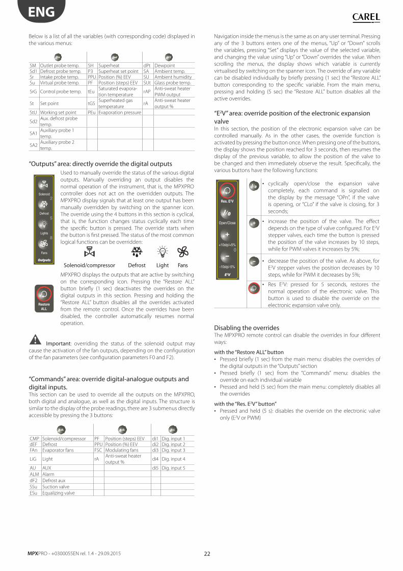
22
ENG
MPXPRO - +0300055EN rel. 1.4 - 29.09.2015
Below is a list of all the variables (with corresponding code) displayed in
the various menus:
Pro Eud ACC
SM Outlet probe temp. SH Superheat dPt Dewpoint
Sd1 Defrost probe temp. P3 Superheat set point SA Ambient temp.
Sr Intake probe temp. PPU Position (%) EEV SU Ambient humidity
Su Virtual probe temp. PF Position (steps) EEV SUt Glass probe temp.
SrG Control probe temp. tEuSaturated evapora-
tion temperaturerAP
Anti-sweat heater
PWM output
St Set point tGSSuperheated gas
temperaturerA
Anti-sweat heater
output %
StU Working set point PEu Evaporation pressure
Sd2Aux. defrost probe
temp.
SA1Auxiliary probe 1
temp.
SA2Auxiliary probe 2
temp.
“Outputs” area: directly override the digital outputs
Lights
Solenoid
Outputs
Defrost
Fans
5
2
8
Used to manually override the status of the various digital
outputs. Manually overriding an output disables the
normal operation of the instrument, that is, the MPXPRO
controller does not act on the overridden outputs. The
MPXPRO display signals that at least one output has been
manually overridden by switching on the spanner icon.
The override using the 4 buttons in this section is cyclical,
that is, the function changes status cyclically each time
the specifi c button is pressed. The override starts when
the button is fi rst pressed. The status of the most common
logical functions can be overridden:
Solenoid/compressor Defrost Light Fans
RestoreALL
MPXPRO displays the outputs that are active by switching
on the corresponding icon. Pressing the “Restore ALL”
button briefl y (1 sec) deactivates the overrides on the
digital outputs in this section. Pressing and holding the
“Restore ALL” button disables all the overrides activated
from the remote control. Once the overrides have been
disabled, the controller automatically resumes normal
operation.
Important: overriding the status of the solenoid output may
cause the activation of the fan outputs, depending on the confi guration
of the fan parameters (see confi guration parameters F0 and F2).
“Commands” area: override digital-analogue outputs and digital inputs.This section can be used to override all the outputs on the MPXPRO,
both digital and analogue, as well as the digital inputs. The structure is
similar to the display of the probe readings, there are 3 submenus directly
accessible by pressing the 3 buttons:
D.O. A.O. D.I.
CMP Solenoid/compressor PF Position (steps) EEV di1 Dig. input 1
dEF Defrost PPU Position (%) EEV di2 Dig. input 2
FAn Evaporator fans FSC Modulating fans di3 Dig. input 3
LiG Light rAAnti-sweat heater
output %di4 Dig. input 4
AU AUX di5 Dig. input 5
ALM Alarm
dF2 Defrost aux
SSu Suction valve
ESu Equalizing valve
Navigation inside the menus is the same as on any user terminal. Pressing
any of the 3 buttons enters one of the menus, “Up” or “Down” scrolls
the variables, pressing “Set” displays the value of the selected variable,
and changing the value using “Up” or “Down” overrides the value. When
scrolling the menus, the display shows which variable is currently
virtualised by switching on the spanner icon. The override of any variable
can be disabled individually by briefl y pressing (1 sec) the “Restore ALL”
button corresponding to the specifi c variable. From the main menu,
pressing and holding (5 sec) the “Restore ALL” button disables all the
active overrides.
“E2V” area: override position of the electronic expansion valveIn this section, the position of the electronic expansion valve can be
controlled manually. As in the other cases, the override function is
activated by pressing the button once. When pressing one of the buttons,
the display shows the position reached for 3 seconds, then resumes the
display of the previous variable, to allow the position of the valve to
be changed and then immediately observe the result. Specifi cally, the
various buttons have the following functions:
Res. E2V
0
+
I/0
E2V
Open/Close
+10stp/+5%
-10stp/-5%
I/0• cyclically open/close the expansion valve
completely, each command is signalled on
the display by the message “OPn”, if the valve
is opening, or “CLo” if the valve is closing, for 3
seconds;
+ • increase the position of the valve. The eff ect
depends on the type of valve confi gured. For E2V
stepper valves, each time the button is pressed
the position of the valve increases by 10 steps,
while for PWM valves it increases by 5%;
• decrease the position of the valve. As above, for
E2V stepper valves the position decreases by 10
steps, while for PWM it decreases by 5%;
• Res E2V: pressed for 5 seconds, restores the
normal operation of the electronic valve. This
button is used to disable the override on the
electronic expansion valve only.
Disabling the overridesThe MPXPRO remote control can disable the overrides in four diff erent
ways:
with the “Restore ALL” button• Pressed briefl y (1 sec) from the main menu: disables the overrides of
the digital outputs in the “Outputs” section
• Pressed briefl y (1 sec) from the “Commands” menu: disables the
override on each individual variable
• Pressed and held (5 sec) from the main menu: completely disables all
the overrides
with the “Res. E2V” button”• Pressed and held (5 s): disables the override on the electronic valve
only (E2V or PWM)
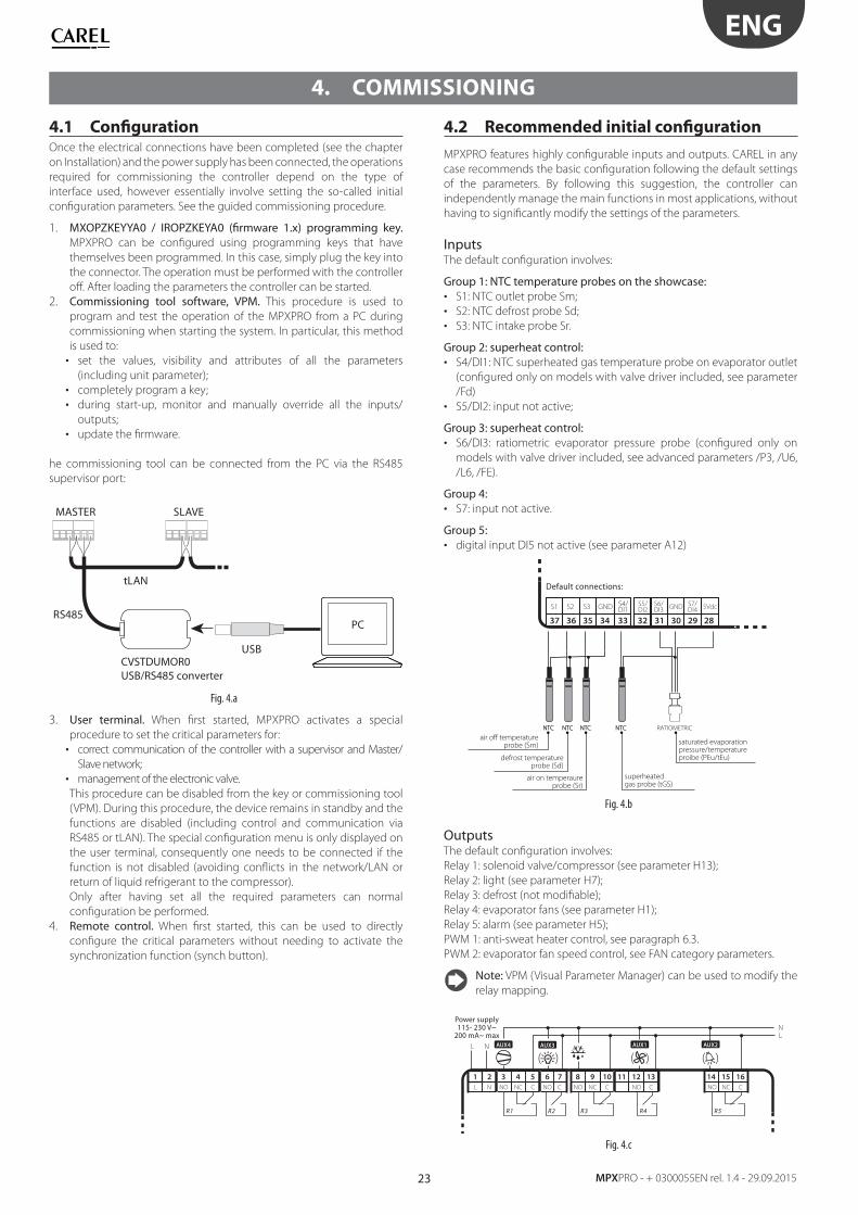
23
ENG
MPXPRO - + 0300055EN rel. 1.4 - 29.09.2015
4. COMMISSIONING
4.1 Confi gurationOnce the electrical connections have been completed (see the chapter
on Installation) and the power supply has been connected, the operations
required for commissioning the controller depend on the type of
interface used, however essentially involve setting the so-called initial
confi guration parameters. See the guided commissioning procedure.
1. MXOPZKEYYA0 / IROPZKEYA0 (fi rmware 1.x) programming key. MPXPRO can be confi gured using programming keys that have
themselves been programmed. In this case, simply plug the key into
the connector. The operation must be performed with the controller
off . After loading the parameters the controller can be started.
2. Commissioning tool software, VPM. This procedure is used to
program and test the operation of the MPXPRO from a PC during
commissioning when starting the system. In particular, this method
is used to:
• set the values, visibility and attributes of all the parameters
(including unit parameter);
• completely program a key;
• during start-up, monitor and manually override all the inputs/
outputs;
• update the fi rmware.
he commissioning tool can be connected from the PC via the RS485
supervisor port:
MASTER SLAVE
USB
RS485
tLAN
CVSTDUMOR0USB/RS485 converter
PC
Fig. 4.a
3. User terminal. When fi rst started, MPXPRO activates a special
procedure to set the critical parameters for:
• correct communication of the controller with a supervisor and Master/
Slave network;
• management of the electronic valve.
This procedure can be disabled from the key or commissioning tool
(VPM). During this procedure, the device remains in standby and the
functions are disabled (including control and communication via
RS485 or tLAN). The special confi guration menu is only displayed on
the user terminal, consequently one needs to be connected if the
function is not disabled (avoiding confl icts in the network/LAN or
return of liquid refrigerant to the compressor).
Only after having set all the required parameters can normal
confi guration be performed.
4. Remote control. When fi rst started, this can be used to directly
confi gure the critical parameters without needing to activate the
synchronization function (synch button).
4.2 Recommended initial confi guration
MPXPRO features highly confi gurable inputs and outputs. CAREL in any
case recommends the basic confi guration following the default settings
of the parameters. By following this suggestion, the controller can
independently manage the main functions in most applications, without
having to signifi cantly modify the settings of the parameters.
Inputs The default confi guration involves:
Group 1: NTC temperature probes on the showcase:• S1: NTC outlet probe Sm;
• S2: NTC defrost probe Sd;
• S3: NTC intake probe Sr.
Group 2: superheat control:• S4/DI1: NTC superheated gas temperature probe on evaporator outlet
(confi gured only on models with valve driver included, see parameter
/Fd)
• S5/DI2: input not active;
Group 3: superheat control:• S6/DI3: ratiometric evaporator pressure probe (confi gured only on
models with valve driver included, see advanced parameters /P3, /U6,
/L6, /FE).
Group 4: • S7: input not active.
Group 5: • digital input DI5 not active (see parameter A12)
5VdcS7/DI4GNDS6/
DI3S5/DI2
36
S2S1 S3
3537 33
S4/DI1GND
3234 30 2931 28
NTC NTC NTC NTC
air off temperatureprobe (Sm)
defrost temperatureprobe (Sd)
air on temperaureprobe (Sr)
superheatedgas probe (tGS)
saturated evaporationpressure/temperatureproibe (PEu/tEu)
NTC NTC NTC NTC RATIOMETRIC
Default connections:
Fig. 4.b
OutputsThe default confi guration involves:
Relay 1: solenoid valve/compressor (see parameter H13);
Relay 2: light (see parameter H7);
Relay 3: defrost (not modifi able);
Relay 4: evaporator fans (see parameter H1);
Relay 5: alarm (see parameter H5);
PWM 1: anti-sweat heater control, see paragraph 6.3.
PWM 2: evaporator fan speed control, see FAN category parameters.
Note: VPM (Visual Parameter Manager) can be used to modify the
relay mapping.
LN
AUX3 AUX1 AUX2
( ( ( (( (
R1 R5R2 R3 R4
L N
8 9
NO NC C
10 11 12
NO C
13 14 15
NCNO C
1632 4
NO NC CNL
6 7
CNO
51
AUX4
Power supply115- 230 V~200 mA~ max
Fig. 4.c
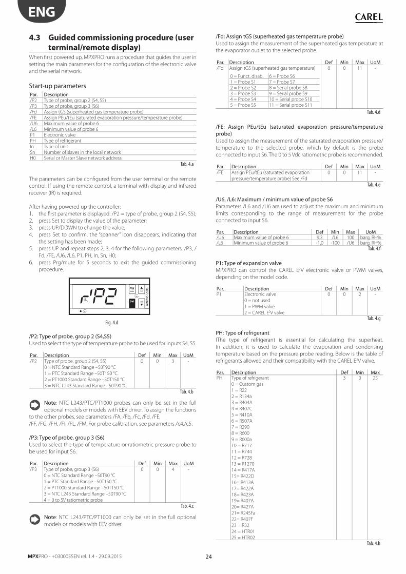
24
ENG
MPXPRO - +0300055EN rel. 1.4 - 29.09.2015
4.3 Guided commissioning procedure (user
terminal/remote display)When fi rst powered up, MPXPRO runs a procedure that guides the user in
setting the main parameters for the confi guration of the electronic valve
and the serial network.
Start-up parametersPar. Description/P2 Type of probe, group 2 (S4, S5)
/P3 Type of probe, group 3 (S6)
/Fd Assign tGS (superheated gas temperature probe)
/FE Assign PEu/tEu (saturated evaporation pressure/temperature probe)
/U6 Maximum value of probe 6
/L6 Minimum value of probe 6
P1 Electronic valve
PH Type of refrigerant
In Type of unit
Sn Number of slaves in the local network
H0 Serial or Master Slave network address
Tab. 4.a
The parameters can be confi gured from the user terminal or the remote
control. If using the remote control, a terminal with display and infrared
receiver (IR) is required.
After having powered up the controller:
1. the fi rst parameter is displayed: /P2 = type of probe, group 2 (S4, S5);
2. press Set to display the value of the parameter;
3. press UP/DOWN to change the value;
4. press Set to confi rm, the “spanner” icon disappears, indicating that
the setting has been made;
5. press UP and repeat steps 2, 3, 4 for the following parameters, /P3, /
Fd, /FE, /U6, /L6, P1, PH, In, Sn, H0;
6. press Prg/mute for 5 seconds to exit the guided commissioning
procedure.
MP
XPR
O
Fig. 4.d
/P2: Type of probe, group 2 (S4,S5) Used to select the type of temperature probe to be used for inputs S4, S5.
Par. Description Def Min Max UoM/P2 Type of probe, group 2 (S4, S5)
0 = NTC Standard Range –50T90 °C
1 = PTC Standard Range –50T150 °C
2 = PT1000 Standard Range –50T150 °C
3 = NTC L243 Standard Range –50T90 °C
0 0 3 -
Tab. 4.b
Note: NTC L243/PTC/PT1000 probes can only be set in the full
optional models or models with EEV driver. To assign the functions
to the other probes, see parameters /FA, /Fb, /Fc, /Fd, /FE,
/FF, /FG, /FH, /FI, /FL, /FM. For probe calibration, see parameters /c4,/c5.
/P3: Type of probe, group 3 (S6) Used to select the type of temperature or ratiometric pressure probe to
be used for input S6.
Par. Description Def Min Max UoM/P3 Type of probe, group 3 (S6)
0 = NTC Standard Range –50T90 °C
1 = PTC Standard Range –50T150 °C
2 = PT1000 Standard Range –50T150 °C
3 = NTC L243 Standard Range –50T90 °C
4 = 0 to 5V ratiometric probe
0 0 4 -
Tab. 4.c
Note: NTC L243/PTC/PT1000 can only be set in the full optional
models or models with EEV driver.
/Fd: Assign tGS (superheated gas temperature probe)Used to assign the measurement of the superheated gas temperature at
the evaporator outlet to the selected probe.
Par. Description Def Min Max UoM/Fd Assign tGS (superheated gas temperature)
0 = Funct. disab. 6 = Probe S6
1 = Probe S1 7 = Probe S7
2 = Probe S2 8 = Serial probe S8
3 = Probe S3 9 = Serial probe S9
4 = Probe S4 10 = Serial probe S10
5 = Probe S5 11 = Serial probe S11
0 0 11 -
Tab. 4.d
/FE: Assign PEu/tEu (saturated evaporation pressure/temperature probe)Used to assign the measurement of the saturated evaporation pressure/
temperature to the selected probe, which by default is the probe
connected to input S6. The 0 to 5 Vdc ratiometric probe is recommended.
Par. Description Def Min Max UoM/FE Assign PEu/tEu (saturated evaporation
pressure/temperature probe) See /Fd
0 0 11 -
Tab. 4.e
/U6, /L6: Maximum / minimum value of probe S6Parameters /L6 and /U6 are used to adjust the maximum and minimum
limits corresponding to the range of measurement for the probe
connected to input S6.
Par. Description Def Min Max UoM/U6 Maximum value of probe 6 9.3 /L6 100 barg, RH%/L6 Minimum value of probe 6 -1.0 -100 /U6 barg, RH%
Tab. 4.f
P1: Type of expansion valve MPXPRO can control the CAREL E2V electronic valve or PWM valves,
depending on the model code.
Par. Description Def Min Max UoMP1 Electronic valve
0 = not used
1 = PWM valve
2 = CAREL E2V valve
0 0 2 -
Tab. 4.g
PH: Type of refrigerantIThe type of refrigerant is essential for calculating the superheat.
In addition, it is used to calculate the evaporation and condensing
temperature based on the pressure probe reading. Below is the table of
refrigerants allowed and their compatibility with the CAREL E2V valve.
Par. Description Def Min MaxPH Type of refrigerant
0 = Custom gas
1 = R22
2 = R134a
3 = R404A
4 = R407C
5 = R410A
6 = R507A
7 = R290
8 = R600
9 = R600a
10 = R717
11 = R744
12 = R728
13 = R1270
14 = R417A
15= R422D
16= R413A
17= R422A
18= R423A
19= R407A
20= R427A
21= R245Fa
22= R407F
23 = R32
24 = HTR01
25 = HTR02
3 0 25
Tab. 4.h
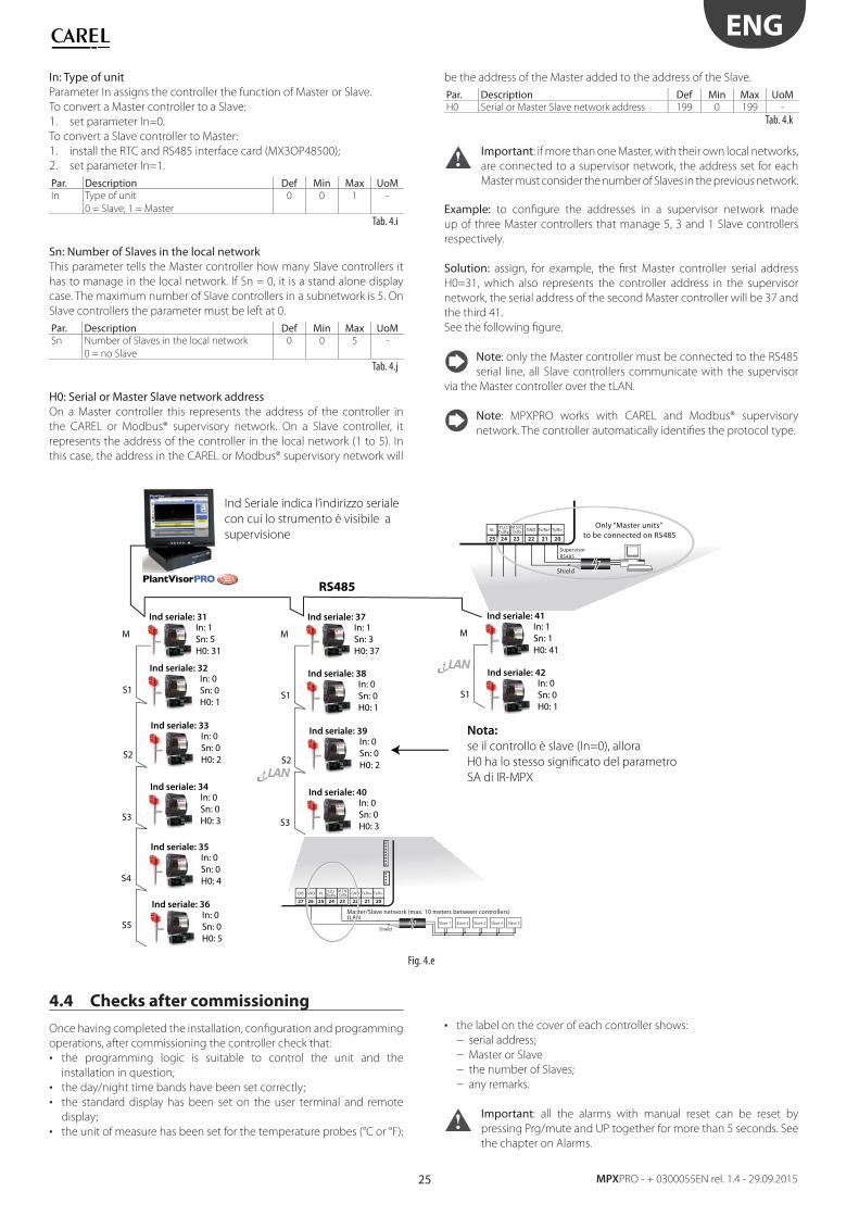
25
ENG
MPXPRO - + 0300055EN rel. 1.4 - 29.09.2015
In: Type of unit Parameter In assigns the controller the function of Master or Slave.
To convert a Master controller to a Slave:
1. set parameter In=0.
To convert a Slave controller to Master:
1. install the RTC and RS485 interface card (MX3OP48500);
2. set parameter In=1.
Par. Description Def Min Max UoMIn Type of unit
0 = Slave; 1 = Master
0 0 1 -
Tab. 4.i
Sn: Number of Slaves in the local network This parameter tells the Master controller how many Slave controllers it
has to manage in the local network. If Sn = 0, it is a stand alone display
case. The maximum number of Slave controllers in a subnetwork is 5. On
Slave controllers the parameter must be left at 0.
Par. Description Def Min Max UoMSn Number of Slaves in the local network
0 = no Slave
0 0 5 -
Tab. 4.j
H0: Serial or Master Slave network addressOn a Master controller this represents the address of the controller in
the CAREL or Modbus® supervisory network. On a Slave controller, it
represents the address of the controller in the local network (1 to 5). In
this case, the address in the CAREL or Modbus® supervisory network will
be the address of the Master added to the address of the Slave.
Par. Description Def Min Max UoMH0 Serial or Master Slave network address 199 0 199 -
Tab. 4.k
Important: if more than one Master, with their own local networks,
are connected to a supervisor network, the address set for each
Master must consider the number of Slaves in the previous network.
Example: to confi gure the addresses in a supervisor network made
up of three Master controllers that manage 5, 3 and 1 Slave controllers
respectively.
Solution: assign, for example, the fi rst Master controller serial address
H0=31, which also represents the controller address in the supervisor
network, the serial address of the second Master controller will be 37 and
the third 41.
See the following fi gure.
Note: only the Master controller must be connected to the RS485
serial line, all Slave controllers communicate with the supervisor
via the Master controller over the tLAN.
Note: MPXPRO works with CAREL and Modbus® supervisory
network. The controller automatically identifi es the protocol type.
Ind seriale: 31In: 1Sn: 5H0: 31
M
Ind seriale: 32In: 0Sn: 0H0: 1
Ind seriale: 33In: 0Sn: 0H0: 2
Ind seriale: 34In: 0Sn: 0H0: 3
Ind seriale: 35In: 0Sn: 0H0: 4
Ind seriale: 36In: 0Sn: 0H0: 5
S1
S2
S3
S4
S5
RS485
Ind seriale: 37In: 1Sn: 3H0: 37
M
Ind seriale: 38In: 0Sn: 0H0: 1
Ind seriale: 39In: 0Sn: 0H0: 2
Ind seriale: 40In: 0Sn: 0H0: 3
S1
S3
Ind seriale: 41In: 1Sn: 1H0: 41
M
Ind seriale: 42In: 0Sn: 0H0: 1
S1
S2
Ind Seriale indica l’indirizzo seriale
con cui lo strumento è visibile a
supervisione
Nota:
se il controllo è slave (In=0), allora
H0 ha lo stesso significato del parametro
SA di IR-MPX
VLGNDDI5 GNDM.S.N.Tx/Rx
T.U.I.Tx/Rx Tx/Rx+ Tx/Rx-
25 242627 2223 2021
Shield
Master/Slave network (max. 10 meters between controllers)tLAN
Slave 1 Slave 2 Slave 4 Slave 5Slave 3
VL GNDM.S.N.Tx/Rx
T.U.I.Tx/Rx Tx/Rx+ Tx/Rx-
25 24 2223 2021
Only “Master units” to be connected on RS485
SupervisorRS485
Shield
Fig. 4.e
4.4 Checks after commissioning
Once having completed the installation, confi guration and programming
operations, after commissioning the controller check that:
• the programming logic is suitable to control the unit and the
installation in question;
• the day/night time bands have been set correctly;
• the standard display has been set on the user terminal and remote
display;
• the unit of measure has been set for the temperature probes (°C or °F);
• the label on the cover of each controller shows:
– serial address;
– Master or Slave
– the number of Slaves;
– any remarks.
Important: all the alarms with manual reset can be reset by
pressing Prg/mute and UP together for more than 5 seconds. See
the chapter on Alarms.
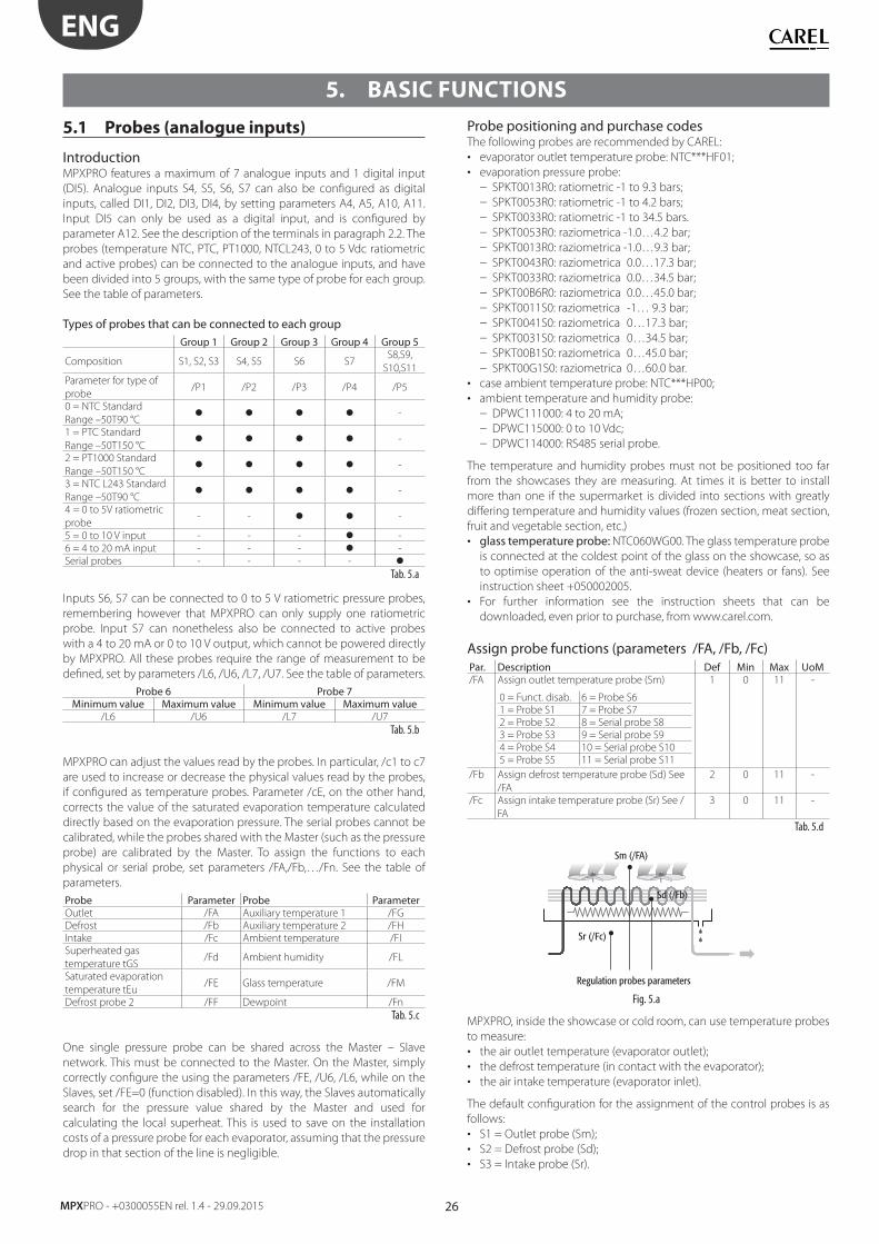
26
ENG
MPXPRO - +0300055EN rel. 1.4 - 29.09.2015
5. BASIC FUNCTIONS
5.1 Probes (analogue inputs)
IntroductionMPXPRO features a maximum of 7 analogue inputs and 1 digital input
(DI5). Analogue inputs S4, S5, S6, S7 can also be confi gured as digital
inputs, called DI1, DI2, DI3, DI4, by setting parameters A4, A5, A10, A11.
Input DI5 can only be used as a digital input, and is confi gured by
parameter A12. See the description of the terminals in paragraph 2.2. The
probes (temperature NTC, PTC, PT1000, NTCL243, 0 to 5 Vdc ratiometric
and active probes) can be connected to the analogue inputs, and have
been divided into 5 groups, with the same type of probe for each group.
See the table of parameters.
Types of probes that can be connected to each groupGroup 1 Group 2 Group 3 Group 4 Group 5
Composition S1, S2, S3 S4, S5 S6 S7S8,S9,
S10,S11
Parameter for type of
probe/P1 /P2 /P3 /P4 /P5
0 = NTC Standard
Range –50T90 °C -
1 = PTC Standard
Range –50T150 °C -
2 = PT1000 Standard
Range –50T150 °C -
3 = NTC L243 Standard
Range –50T90 °C -
4 = 0 to 5V ratiometric
probe- - -
5 = 0 to 10 V input - - - -
6 = 4 to 20 mA input - - - -
Serial probes - - - - Tab. 5.a
Inputs S6, S7 can be connected to 0 to 5 V ratiometric pressure probes,
remembering however that MPXPRO can only supply one ratiometric
probe. Input S7 can nonetheless also be connected to active probes
with a 4 to 20 mA or 0 to 10 V output, which cannot be powered directly
by MPXPRO. All these probes require the range of measurement to be
defi ned, set by parameters /L6, /U6, /L7, /U7. See the table of parameters.
Probe 6 Probe 7Minimum value Maximum value Minimum value Maximum value
/L6 /U6 /L7 /U7
Tab. 5.b
MPXPRO can adjust the values read by the probes. In particular, /c1 to c7
are used to increase or decrease the physical values read by the probes,
if confi gured as temperature probes. Parameter /cE, on the other hand,
corrects the value of the saturated evaporation temperature calculated
directly based on the evaporation pressure. The serial probes cannot be
calibrated, while the probes shared with the Master (such as the pressure
probe) are calibrated by the Master. To assign the functions to each
physical or serial probe, set parameters /FA,/Fb,…/Fn. See the table of
parameters.
Probe Parameter Probe ParameterOutlet /FA Auxiliary temperature 1 /FG
Defrost /Fb Auxiliary temperature 2 /FH
Intake /Fc Ambient temperature /FI
Superheated gas
temperature tGS/Fd Ambient humidity /FL
Saturated evaporation
temperature tEu/FE Glass temperature /FM
Defrost probe 2 /FF Dewpoint /Fn
Tab. 5.c
One single pressure probe can be shared across the Master – Slave
network. This must be connected to the Master. On the Master, simply
correctly confi gure the using the parameters /FE, /U6, /L6, while on the
Slaves, set /FE=0 (function disabled). In this way, the Slaves automatically
search for the pressure value shared by the Master and used for
calculating the local superheat. This is used to save on the installation
costs of a pressure probe for each evaporator, assuming that the pressure
drop in that section of the line is negligible.
Probe positioning and purchase codesThe following probes are recommended by CAREL:
• evaporator outlet temperature probe: NTC***HF01;
• evaporation pressure probe:
– SPKT0013R0: ratiometric -1 to 9.3 bars;
– SPKT0053R0: ratiometric -1 to 4.2 bars;
– SPKT0033R0: ratiometric -1 to 34.5 bars.
– SPKT0053R0: raziometrica -1.0…4.2 bar;
– SPKT0013R0: raziometrica -1.0…9.3 bar;
– SPKT0043R0: raziometrica 0.0…17.3 bar;
– SPKT0033R0: raziometrica 0.0…34.5 bar;
– SPKT00B6R0: raziometrica 0.0…45.0 bar;
– SPKT0011S0: raziometrica -1… 9.3 bar;
– SPKT0041S0: raziometrica 0…17.3 bar;
– SPKT0031S0: raziometrica 0…34.5 bar;
– SPKT00B1S0: raziometrica 0…45.0 bar;
– SPKT00G1S0: raziometrica 0…60.0 bar.
• case ambient temperature probe: NTC***HP00;
• ambient temperature and humidity probe:
– DPWC111000: 4 to 20 mA;
– DPWC115000: 0 to 10 Vdc;
– DPWC114000: RS485 serial probe.
The temperature and humidity probes must not be positioned too far
from the showcases they are measuring. At times it is better to install
more than one if the supermarket is divided into sections with greatly
diff ering temperature and humidity values (frozen section, meat section,
fruit and vegetable section, etc.)
• glass temperature probe: NTC060WG00. The glass temperature probe
is connected at the coldest point of the glass on the showcase, so as
to optimise operation of the anti-sweat device (heaters or fans). See
instruction sheet +050002005.
• For further information see the instruction sheets that can be
downloaded, even prior to purchase, from www.carel.com.
Assign probe functions (parameters /FA, /Fb, /Fc)Par. Description Def Min Max UoM/FA Assign outlet temperature probe (Sm)
0 = Funct. disab. 6 = Probe S6
1 = Probe S1 7 = Probe S7
2 = Probe S2 8 = Serial probe S8
3 = Probe S3 9 = Serial probe S9
4 = Probe S4 10 = Serial probe S10
5 = Probe S5 11 = Serial probe S11
1 0 11 -
/Fb Assign defrost temperature probe (Sd) See
/FA
2 0 11 -
/Fc Assign intake temperature probe (Sr) See /
FA
3 0 11 -
Tab. 5.d
Sm (/FA)
Sr (/Fc)
Regulation probes parameters
Sd (/Fb)
Fig. 5.a
MPXPRO, inside the showcase or cold room, can use temperature probes
to measure:
• the air outlet temperature (evaporator outlet);
• the defrost temperature (in contact with the evaporator);
• the air intake temperature (evaporator inlet).
The default confi guration for the assignment of the control probes is as
follows:
• S1 = Outlet probe (Sm);
• S2 = Defrost probe (Sd);
• S3 = Intake probe (Sr).
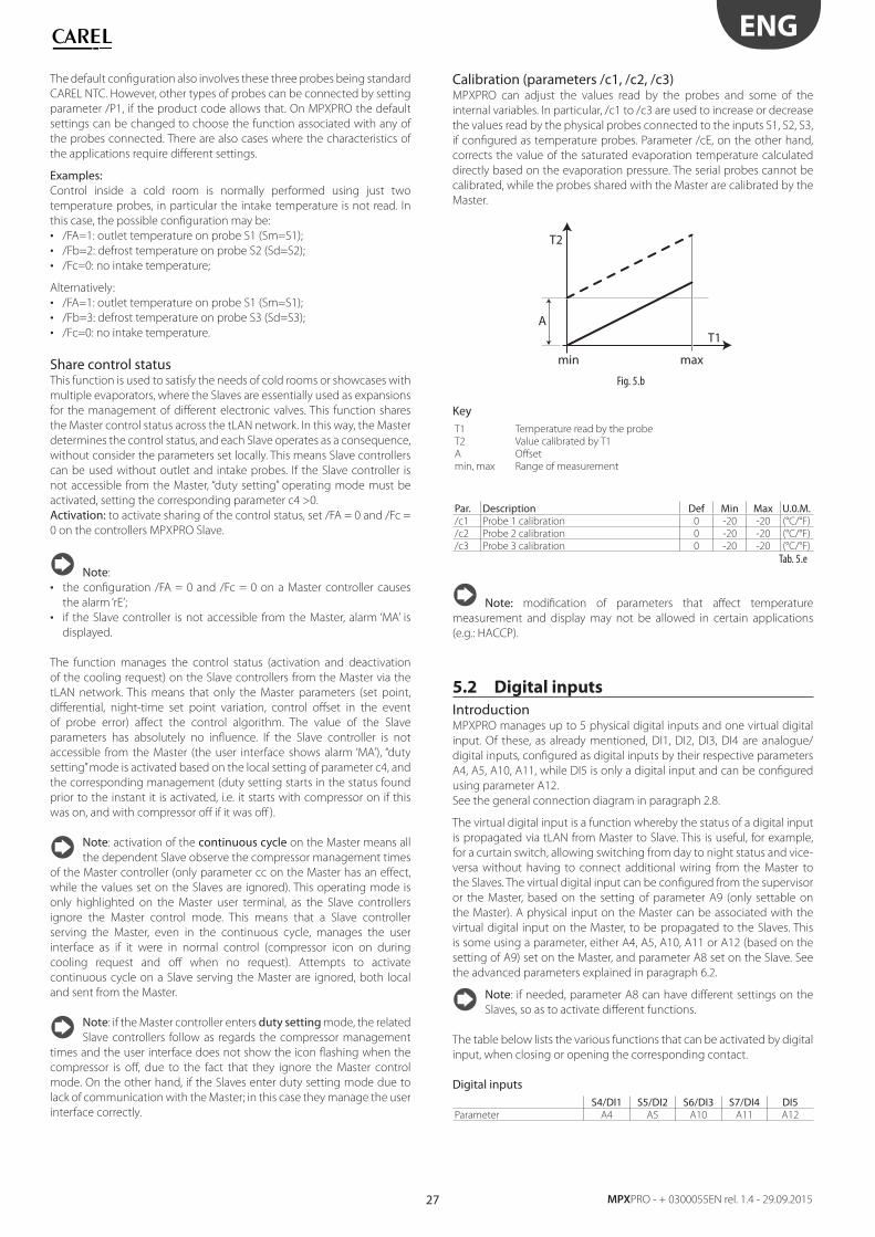
27
ENG
MPXPRO - + 0300055EN rel. 1.4 - 29.09.2015
The default confi guration also involves these three probes being standard
CAREL NTC. However, other types of probes can be connected by setting
parameter /P1, if the product code allows that. On MPXPRO the default
settings can be changed to choose the function associated with any of
the probes connected. There are also cases where the characteristics of
the applications require diff erent settings.
Examples:Control inside a cold room is normally performed using just two
temperature probes, in particular the intake temperature is not read. In
this case, the possible confi guration may be:
• /FA=1: outlet temperature on probe S1 (Sm=S1);
• /Fb=2: defrost temperature on probe S2 (Sd=S2);
• /Fc=0: no intake temperature;
Alternatively:
• /FA=1: outlet temperature on probe S1 (Sm=S1);
• /Fb=3: defrost temperature on probe S3 (Sd=S3);
• /Fc=0: no intake temperature.
Share control statusThis function is used to satisfy the needs of cold rooms or showcases with
multiple evaporators, where the Slaves are essentially used as expansions
for the management of diff erent electronic valves. This function shares
the Master control status across the tLAN network. In this way, the Master
determines the control status, and each Slave operates as a consequence,
without consider the parameters set locally. This means Slave controllers
can be used without outlet and intake probes. If the Slave controller is
not accessible from the Master, “duty setting” operating mode must be
activated, setting the corresponding parameter c4 >0.
Activation: to activate sharing of the control status, set /FA = 0 and /Fc =
0 on the controllers MPXPRO Slave.
Note:
• the confi guration /FA = 0 and /Fc = 0 on a Master controller causes
the alarm ‘rE’;
• if the Slave controller is not accessible from the Master, alarm ‘MA’ is
displayed.
The function manages the control status (activation and deactivation
of the cooling request) on the Slave controllers from the Master via the
tLAN network. This means that only the Master parameters (set point,
diff erential, night-time set point variation, control off set in the event
of probe error) aff ect the control algorithm. The value of the Slave
parameters has absolutely no infl uence. If the Slave controller is not
accessible from the Master (the user interface shows alarm ‘MA’), “duty
setting” mode is activated based on the local setting of parameter c4, and
the corresponding management (duty setting starts in the status found
prior to the instant it is activated, i.e. it starts with compressor on if this
was on, and with compressor off if it was off ).
Note: activation of the continuous cycle on the Master means all
the dependent Slave observe the compressor management times
of the Master controller (only parameter cc on the Master has an eff ect,
while the values set on the Slaves are ignored). This operating mode is
only highlighted on the Master user terminal, as the Slave controllers
ignore the Master control mode. This means that a Slave controller
serving the Master, even in the continuous cycle, manages the user
interface as if it were in normal control (compressor icon on during
cooling request and off when no request). Attempts to activate
continuous cycle on a Slave serving the Master are ignored, both local
and sent from the Master.
Note: if the Master controller enters duty setting mode, the related
Slave controllers follow as regards the compressor management
times and the user interface does not show the icon fl ashing when the
compressor is off , due to the fact that they ignore the Master control
mode. On the other hand, if the Slaves enter duty setting mode due to
lack of communication with the Master; in this case they manage the user
interface correctly.
Calibration (parameters /c1, /c2, /c3)MPXPRO can adjust the values read by the probes and some of the
internal variables. In particular, /c1 to /c3 are used to increase or decrease
the values read by the physical probes connected to the inputs S1, S2, S3,
if confi gured as temperature probes. Parameter /cE, on the other hand,
corrects the value of the saturated evaporation temperature calculated
directly based on the evaporation pressure. The serial probes cannot be
calibrated, while the probes shared with the Master are calibrated by the
Master.
AT1
T2
min max
Fig. 5.b
KeyT1 Temperature read by the probe
T2 Value calibrated by T1
A Off set
min, max Range of measurement
Par. Description Def Min Max U.0.M./c1 Probe 1 calibration 0 -20 -20 (°C/°F)
/c2 Probe 2 calibration 0 -20 -20 (°C/°F)
/c3 Probe 3 calibration 0 -20 -20 (°C/°F)
Tab. 5.e
Note: modifi cation of parameters that aff ect temperature
measurement and display may not be allowed in certain applications
(e.g.: HACCP).
5.2 Digital inputs
IntroductionMPXPRO manages up to 5 physical digital inputs and one virtual digital
input. Of these, as already mentioned, DI1, DI2, DI3, DI4 are analogue/
digital inputs, confi gured as digital inputs by their respective parameters
A4, A5, A10, A11, while DI5 is only a digital input and can be confi gured
using parameter A12.
See the general connection diagram in paragraph 2.8.
The virtual digital input is a function whereby the status of a digital input
is propagated via tLAN from Master to Slave. This is useful, for example,
for a curtain switch, allowing switching from day to night status and vice-
versa without having to connect additional wiring from the Master to
the Slaves. The virtual digital input can be confi gured from the supervisor
or the Master, based on the setting of parameter A9 (only settable on
the Master). A physical input on the Master can be associated with the
virtual digital input on the Master, to be propagated to the Slaves. This
is some using a parameter, either A4, A5, A10, A11 or A12 (based on the
setting of A9) set on the Master, and parameter A8 set on the Slave. See
the advanced parameters explained in paragraph 6.2.
Note: if needed, parameter A8 can have diff erent settings on the
Slaves, so as to activate diff erent functions.
The table below lists the various functions that can be activated by digital
input, when closing or opening the corresponding contact.
Digital inputsS4/DI1 S5/DI2 S6/DI3 S7/DI4 DI5
Parameter A4 A5 A10 A11 A12
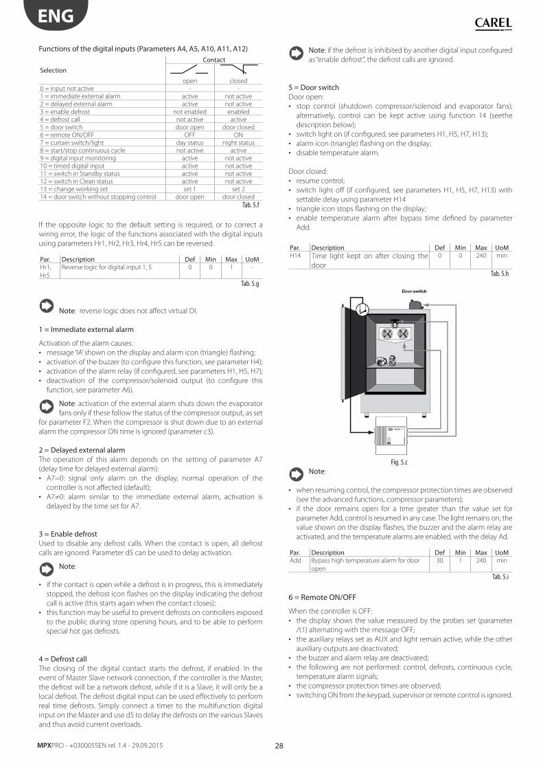
28
ENG
MPXPRO - +0300055EN rel. 1.4 - 29.09.2015
Functions of the digital inputs (Parameters A4, A5, A10, A11, A12)
Selection
Contact
open closed
0 = input not active - -
1 = immediate external alarm active not active
2 = delayed external alarm active not active
3 = enable defrost not enabled enabled
4 = defrost call not active active
5 = door switch door open door closed
6 = remote ON/OFF OFF ON
7 = curtain switch/light day status night status
8 = start/stop continuous cycle not active active
9 = digital input monitoring active not active
10 = timed digital input active not active
11 = switch in Standby status active not active
12 = switch in Clean status active not active
13 = change working set set 1 set 2
14 = door switch without stopping control door open door closed
Tab. 5.f
If the opposite logic to the default setting is required, or to correct a
wiring error, the logic of the functions associated with the digital inputs
using parameters Hr1, Hr2, Hr3, Hr4, Hr5 can be reversed.
Par. Description Def Min Max UoMHr1,
Hr5
Reverse logic for digital input 1, 5 0 0 1 -
Tab. 5.g
Note: reverse logic does not aff ect virtual DI.
1 = Immediate external alarm
Activation of the alarm causes:
• message ‘IA’ shown on the display and alarm icon (triangle) fl ashing;
• activation of the buzzer (to confi gure this function, see parameter H4);
• activation of the alarm relay (if confi gured, see parameters H1, H5, H7);
• deactivation of the compressor/solenoid output (to confi gure this
function, see parameter A6).
Note: activation of the external alarm shuts down the evaporator
fans only if these follow the status of the compressor output, as set
for parameter F2. When the compressor is shut down due to an external
alarm the compressor ON time is ignored (parameter c3).
2 = Delayed external alarmThe operation of this alarm depends on the setting of parameter A7
(delay time for delayed external alarm):
• A7=0: signal only alarm on the display, normal operation of the
controller is not aff ected (default);
• A7≠0: alarm similar to the immediate external alarm, activation is
delayed by the time set for A7.
3 = Enable defrostUsed to disable any defrost calls. When the contact is open, all defrost
calls are ignored. Parameter d5 can be used to delay activation.
Note:
• if the contact is open while a defrost is in progress, this is immediately
stopped, the defrost icon fl ashes on the display indicating the defrost
call is active (this starts again when the contact closes);
• this function may be useful to prevent defrosts on controllers exposed
to the public during store opening hours, and to be able to perform
special hot gas defrosts.
4 = Defrost callThe closing of the digital contact starts the defrost, if enabled. In the
event of Master Slave network connection, if the controller is the Master,
the defrost will be a network defrost, while if it is a Slave, it will only be a
local defrost. The defrost digital input can be used eff ectively to perform
real time defrosts. Simply connect a timer to the multifunction digital
input on the Master and use d5 to delay the defrosts on the various Slaves
and thus avoid current overloads.
Note: if the defrost is inhibited by another digital input confi gured
as “enable defrost”, the defrost calls are ignored.
5 = Door switchDoor open:
• stop control (shutdown compressor/solenoid and evaporator fans);
alternatively, control can be kept active using function 14 (seethe
description below);
• switch light on (if confi gured, see parameters H1, H5, H7, H13);
• alarm icon (triangle) fl ashing on the display;
• disable temperature alarm.
Door closed:
• resume control;
• switch light off (if confi gured, see parameters H1, H5, H7, H13) with
settable delay using parameter H14
• triangle icon stops fl ashing on the display;
• enable temperature alarm after bypass time defi ned by parameter
Add.
Par. Description Def Min Max UoMH14 Time light kept on after closing the
door
0 0 240 min
Tab. 5.h
MPXPRO
Fig. 5.c
Note:
• when resuming control, the compressor protection times are observed
(see the advanced functions, compressor parameters);
• if the door remains open for a time greater than the value set for
parameter Add, control is resumed in any case. The light remains on, the
value shown on the display fl ashes, the buzzer and the alarm relay are
activated, and the temperature alarms are enabled, with the delay Ad.
Par. Description Def Min Max UoMAdd Bypass high temperature alarm for door
open
30 1 240 min
Tab. 5.i
6 = Remote ON/OFF
When the controller is OFF:
• the display shows the value measured by the probes set (parameter
/t1) alternating with the message OFF;
• the auxiliary relays set as AUX and light remain active, while the other
auxiliary outputs are deactivated;
• the buzzer and alarm relay are deactivated;
• the following are not performed: control, defrosts, continuous cycle,
temperature alarm signals;
• the compressor protection times are observed;
• switching ON from the keypad, supervisor or remote control is ignored.
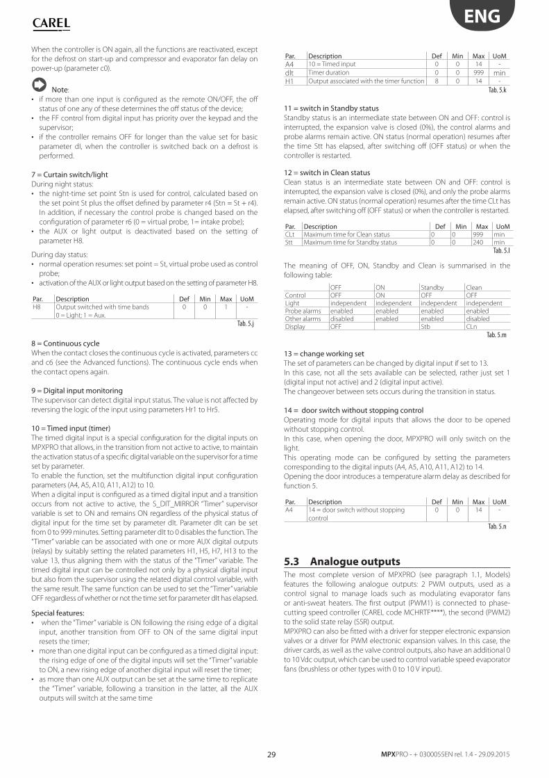
29
ENG
MPXPRO - + 0300055EN rel. 1.4 - 29.09.2015
When the controller is ON again, all the functions are reactivated, except
for the defrost on start-up and compressor and evaporator fan delay on
power-up (parameter c0).
Note:
• if more than one input is confi gured as the remote ON/OFF, the off
status of one any of these determines the off status of the device;
• the FF control from digital input has priority over the keypad and the
supervisor;
• if the controller remains OFF for longer than the value set for basic
parameter dI, when the controller is switched back on a defrost is
performed.
7 = Curtain switch/light During night status:
• the night-time set point Stn is used for control, calculated based on
the set point St plus the off set defi ned by parameter r4 (Stn = St + r4).
In addition, if necessary the control probe is changed based on the
confi guration of parameter r6 (0 = virtual probe, 1= intake probe);
• the AUX or light output is deactivated based on the setting of
parameter H8.
During day status:
• normal operation resumes: set point = St, virtual probe used as control
probe;
• activation of the AUX or light output based on the setting of parameter H8.
Par. Description Def Min Max UoMH8 Output switched with time bands
0 = Light; 1 = Aux.
0 0 1 -
Tab. 5.j
8 = Continuous cycle When the contact closes the continuous cycle is activated, parameters cc
and c6 (see the Advanced functions). The continuous cycle ends when
the contact opens again.
9 = Digital input monitoringThe supervisor can detect digital input status. The value is not aff ected by
reversing the logic of the input using parameters Hr1 to Hr5.
10 = Timed input (timer)The timed digital input is a special confi guration for the digital inputs on
MPXPRO that allows, in the transition from not active to active, to maintain
the activation status of a specifi c digital variable on the supervisor for a time
set by parameter.
To enable the function, set the multifunction digital input confi guration
parameters (A4, A5, A10, A11, A12) to 10.
When a digital input is confi gured as a timed digital input and a transition
occurs from not active to active, the S_DIT_MIRROR “Timer” supervisor
variable is set to ON and remains ON regardless of the physical status of
digital input for the time set by parameter dIt. Parameter dIt can be set
from 0 to 999 minutes. Setting parameter dIt to 0 disables the function. The
“Timer” variable can be associated with one or more AUX digital outputs
(relays) by suitably setting the related parameters H1, H5, H7, H13 to the
value 13, thus aligning them with the status of the “Timer” variable. The
timed digital input can be controlled not only by a physical digital input
but also from the supervisor using the related digital control variable, with
the same result. The same function can be used to set the “Timer” variable
OFF regardless of whether or not the time set for parameter dIt has elapsed.
Special features:• when the “Timer” variable is ON following the rising edge of a digital
input, another transition from OFF to ON of the same digital input
resets the timer;
• more than one digital input can be confi gured as a timed digital input:
the rising edge of one of the digital inputs will set the “Timer” variable
to ON, a new rising edge of another digital input will reset the timer;
• as more than one AUX output can be set at the same time to replicate
the “Timer” variable, following a transition in the latter, all the AUX
outputs will switch at the same time
Par. Description Def Min Max UoMA4 10 = Timed input 0 0 14 -
dlt Timer duration 0 0 999 minH1 Output associated with the timer function 8 0 14 -
Tab. 5.k
11 = switch in Standby statusStandby status is an intermediate state between ON and OFF: control is
interrupted, the expansion valve is closed (0%), the control alarms and
probe alarms remain active. ON status (normal operation) resumes after
the time Stt has elapsed, after switching off (OFF status) or when the
controller is restarted.
12 = switch in Clean statusClean status is an intermediate state between ON and OFF: control is
interrupted, the expansion valve is closed (0%), and only the probe alarms
remain active. ON status (normal operation) resumes after the time CLt has
elapsed, after switching off (OFF status) or when the controller is restarted.
Par. Description Def Min Max UoMCLt Maximum time for Clean status 0 0 999 min
Stt Maximum time for Standby status 0 0 240 min
Tab. 5.l
The meaning of OFF, ON, Standby and Clean is summarised in the
following table:
OFF ON Standby Clean
Control OFF ON OFF OFF
Light independent independent independent independent
Probe alarms enabled enabled enabled enabled
Other alarms disabled enabled enabled disabled
Display OFF Stb CLn
Tab. 5.m
13 = change working setThe set of parameters can be changed by digital input if set to 13.
In this case, not all the sets available can be selected, rather just set 1
(digital input not active) and 2 (digital input active).
The changeover between sets occurs during the transition in status.
14 = door switch without stopping controlOperating mode for digital inputs that allows the door to be opened
without stopping control.
In this case, when opening the door, MPXPRO will only switch on the
light.
This operating mode can be confi gured by setting the parameters
corresponding to the digital inputs (A4, A5, A10, A11, A12) to 14.
Opening the door introduces a temperature alarm delay as described for
function 5.
Par. Description Def Min Max UoMA4 14 = door switch without stopping
control
0 0 14 -
Tab. 5.n
5.3 Analogue outputsThe most complete version of MPXPRO (see paragraph 1.1, Models)
features the following analogue outputs: 2 PWM outputs, used as a
control signal to manage loads such as modulating evaporator fans
or anti-sweat heaters. The fi rst output (PWM1) is connected to phase-
cutting speed controller (CAREL code MCHRTF****), the second (PWM2)
to the solid state relay (SSR) output.
MPXPRO can also be fi tted with a driver for stepper electronic expansion
valves or a driver for PWM electronic expansion valves. In this case, the
driver cards, as well as the valve control outputs, also have an additional 0
to 10 Vdc output, which can be used to control variable speed evaporator
fans (brushless or other types with 0 to 10 V input).
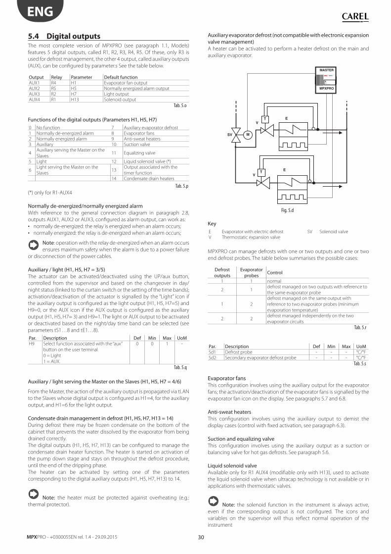
30
ENG
MPXPRO - +0300055EN rel. 1.4 - 29.09.2015
5.4 Digital outputsThe most complete version of MPXPRO (see paragraph 1.1, Models)
features 5 digital outputs, called R1, R2, R3, R4, R5. Of these, only R3 is
used for defrost management, the other 4 output, called auxiliary outputs
(AUX), can be confi gured by parameter.s See the table below.
Output Relay Parameter Default functionAUX1 R4 H1 Evaporator fan output
AUX2 R5 H5 Normally energized alarm output
AUX3 R2 H7 Light output
AUX4 R1 H13 Solenoid output
Tab. 5.o
Functions of the digital outputs (Parameters H1, H5, H7)0 No function 7 Auxiliary evaporator defrost
1 Normally de-energized alarm 8 Evaporator fans
2 Normally energized alarm 9 Anti-sweat heaters
3 Auxiliary 10 Suction valve
4Auxiliary serving the Master on the
Slaves11 Equalizing valve
5 Light 12 Liquid solenoid valve (*)
6Light serving the Master on the
Slaves13
Output associated with the
timer function
14 Condensate drain heaters
Tab. 5.p
(*) only for R1-AUX4
Normally de-energized/normally energized alarmWith reference to the general connection diagram in paragraph 2.8,
outputs AUX1, AUX2 or AUX3, confi gured as alarm output, can work as:
• normally de-energized: the relay is energized when an alarm occurs;
• normally energized: the relay is de-energized when an alarm occurs;
Note: operation with the relay de-energized when an alarm occurs
ensures maximum safety when the alarm is due to a power failure
or disconnection of the power cables.
Auxiliary / light (H1, H5, H7 = 3/5)The actuator can be activated/deactivated using the UP/aux button,
controlled from the supervisor and based on the changeover in day/
night status (linked to the curtain switch or the setting of the time bands);
activation/deactivation of the actuator is signalled by the “Light” icon if
the auxiliary output is confi gured as the light output (H1, H5, H7=5) and
H9=0, or the AUX icon if the AUX output is confi gured as the auxiliary
output (H1, H5, H7= 3) and H9=1. The light or AUX output to be activated
or deactivated based on the night/day time band can be selected (see
parameters tS1…8 and tE1…8).
Par. Description Def Min Max UoMH9 Select function associated with the “aux”
button on the user terminal
0 = Light
1 = AUX.
0 0 1 -
Tab. 5.q
Auxiliary / light serving the Master on the Slaves (H1, H5, H7 = 4/6)
From the Master, the action of the auxiliary output is propagated via tLAN
to the Slaves whose digital output is confi gured as H1=4, for the auxiliary
output, and H1=6 for the light output.
Condensate drain management in defrost (H1, H5, H7, H13 = 14)During defrost there may be frozen condensate on the bottom of the
cabinet that prevents the water dissolved by the evaporator from being
drained correctly.
The digital outputs (H1, H5, H7, H13) can be confi gured to manage the
condensate drain heater function. The heater is started on activation of
the pump down stage and stays on throughout the defrost procedure,
until the end of the dripping phase.
The heater can be activated by setting one of the parameters
corresponding to the digital auxiliary outputs (H1, H5, H7, H13) to 14.
Note: the heater must be protected against overheating (e.g.:
thermal protector).
Auxiliary evaporator defrost (not compatible with electronic expansion valve management)A heater can be activated to perform a heater defrost on the main and
auxiliary evaporator.
M
MPXPROCAREL
!
MASTER
SV
MPXPRO
E
E
T
TV
V
Fig. 5.d
KeyE Evaporator with electric defrost SV Solenoid valve
V Thermostatic expansion valve
MPXPRO can manage defrosts with one or two outputs and one or two
end defrost probes. The table below summarises the possible cases:
Defrost outputs
Evaporator probes
Control
1 1 normal
2 1defrost managed on two outputs with reference to
the same evaporator probe
1 2
defrost managed on the same output with
reference to two evaporator probes (minimum
evaporation temperature)
2 2defrost managed independently on the two
evaporator circuits
Tab. 5.r
Par. Description Def Min Max UoMSd1 Defrost probe - - - °C/°F
Sd2 Secondary evaporator defrost probe - - - °C/°F
Tab. 5.s
Evaporator fansThis confi guration involves using the auxiliary output for the evaporator
fans; the activation/deactivation of the evaporator fans is signalled by the
evaporator fan icon on the display. See paragraphs 5.7 and 6.8.
Anti-sweat heatersThis confi guration involves using the auxiliary output to demist the
display cases (control with fi xed activation, see paragraph 6.3).
Suction and equalizing valveThis confi guration involves using the auxiliary output as a suction or
balancing valve for hot gas defrosts. See paragraph 5.6.
Liquid solenoid valveAvailable only for R1 AUX4 (modifi able only with H13), used to activate
the liquid solenoid valve when ultracap technology is not available or in
applications with thermostatic valves.
Note: the solenoid function in the instrument is always active,
even if the corresponding output is not confi gured. The icons and
variables on the supervisor will thus refl ect normal operation of the
instrument
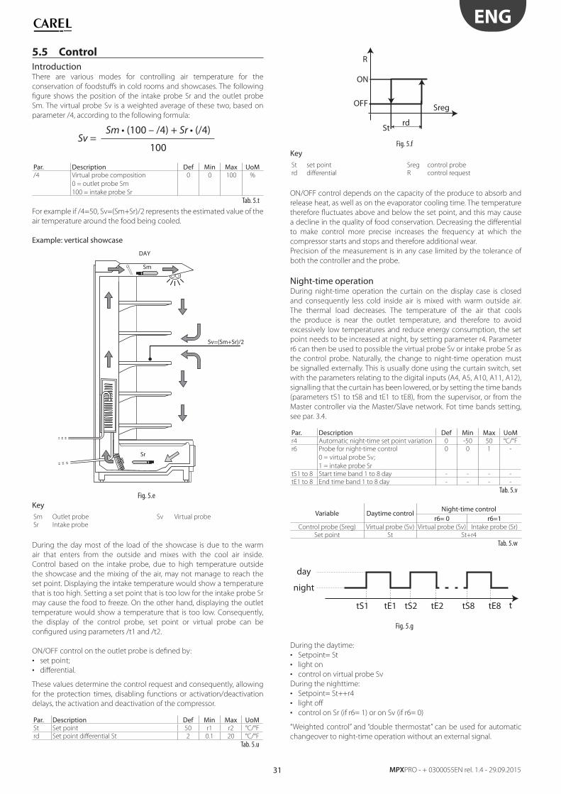
31
ENG
MPXPRO - + 0300055EN rel. 1.4 - 29.09.2015
5.5 Control
IntroductionThere are various modes for controlling air temperature for the
conservation of foodstuff s in cold rooms and showcases. The following
fi gure shows the position of the intake probe Sr and the outlet probe
Sm. The virtual probe Sv is a weighted average of these two, based on
parameter /4, according to the following formula:
Sv =Sm Sr
Par. Description Def Min Max UoM/4 Virtual probe composition
0 = outlet probe Sm
100 = intake probe Sr
0 0 100 %
Tab. 5.t
For example if /4=50, Sv=(Sm+Sr)/2 represents the estimated value of the
air temperature around the food being cooled.
Example: vertical showcase
DAY
Sm
Sv=(Sm+Sr)/2
Sr
Fig. 5.e
KeySm Outlet probe Sv Virtual probe
Sr Intake probe
During the day most of the load of the showcase is due to the warm
air that enters from the outside and mixes with the cool air inside.
Control based on the intake probe, due to high temperature outside
the showcase and the mixing of the air, may not manage to reach the
set point. Displaying the intake temperature would show a temperature
that is too high. Setting a set point that is too low for the intake probe Sr
may cause the food to freeze. On the other hand, displaying the outlet
temperature would show a temperature that is too low. Consequently,
the display of the control probe, set point or virtual probe can be
confi gured using parameters /t1 and /t2.
ON/OFF control on the outlet probe is defi ned by:
• set point;
• diff erential.
These values determine the control request and consequently, allowing
for the protection times, disabling functions or activation/deactivation
delays, the activation and deactivation of the compressor.
Par. Description Def Min Max UoMSt Set point 50 r1 r2 °C/°F
rd Set point diff erential St 2 0.1 20 °C/°F
Tab. 5.u
Sreg
rdSt
ON
R
OFF
Fig. 5.f
KeySt set point Sreg control probe
rd diff erential R control request
ON/OFF control depends on the capacity of the produce to absorb and
release heat, as well as on the evaporator cooling time. The temperature
therefore fl uctuates above and below the set point, and this may cause
a decline in the quality of food conservation. Decreasing the diff erential
to make control more precise increases the frequency at which the
compressor starts and stops and therefore additional wear.
Precision of the measurement is in any case limited by the tolerance of
both the controller and the probe.
Night-time operationDuring night-time operation the curtain on the display case is closed
and consequently less cold inside air is mixed with warm outside air.
The thermal load decreases. The temperature of the air that cools
the produce is near the outlet temperature, and therefore to avoid
excessively low temperatures and reduce energy consumption, the set
point needs to be increased at night, by setting parameter r4. Parameter
r6 can then be used to possible the virtual probe Sv or intake probe Sr as
the control probe. Naturally, the change to night-time operation must
be signalled externally. This is usually done using the curtain switch, set
with the parameters relating to the digital inputs (A4, A5, A10, A11, A12),
signalling that the curtain has been lowered, or by setting the time bands
(parameters tS1 to tS8 and tE1 to tE8), from the supervisor, or from the
Master controller via the Master/Slave network. Fot time bands setting,
see par. 3.4.
Par. Description Def Min Max UoMr4 Automatic night-time set point variation 0 -50 50 °C/°F
r6 Probe for night-time control
0 = virtual probe Sv;
1 = intake probe Sr
0 0 1 -
tS1 to 8 Start time band 1 to 8 day - - - -
tE1 to 8 End time band 1 to 8 day - - - -
Tab. 5.v
Variable Daytime controlNight-time control
r6= 0 r6=1Control probe (Sreg) Virtual probe (Sv) Virtual probe (Sv) Intake probe (Sr)
Set point St St+r4
Tab. 5.w
t
night
tS1
day
tE1 tS2 tE2 tS8 tE8
Fig. 5.g
During the daytime:
• Setpoint= St
• light on
• control on virtual probe Sv
During the nighttime:
• Setpoint= St++r4
• light off
• control on Sr (if r6= 1) or on Sv (if r6= 0)
“Weighted control” and “double thermostat” can be used for automatic
changeover to night-time operation without an external signal.
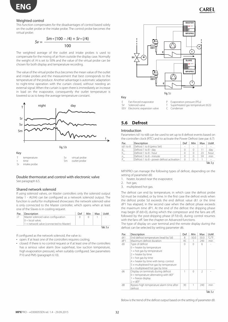
32
ENG
MPXPRO - +0300055EN rel. 1.4 - 29.09.2015
Weighted controlThis function compensates for the disadvantages of control based solely
on the outlet probe or the intake probe. The control probe becomes the
virtual probe:
Sv =Sm Sr
The weighted average of the outlet and intake probes is used to
compensate for the mixing of air from outside the display case. Normally
the weight of /4 is set to 50% and the value of the virtual probe can be
chosen for both display and temperature recording.
The value of the virtual probe thus becomes the mean value of the outlet
and intake probes and the measurement that best corresponds to the
temperature of the produce. Another advantage is automatic adaptation
to night-time operation with the curtain closed, without needing an
external signal. When the curtain is open there is immediately an increase
in load on the evaporator, consequently the outlet temperature is
lowered so as to keep the average temperature constant.
t
T night day
Sr
Sm
Sv
Fig. 5.h
KeyT temperature Sv virtual probe
t time Sm outlet probe
Sr intake probe
Double thermostat and control with electronic valveSee paragraph 6.5.
Shared network solenoidIf using solenoid valves, on Master controllers only the solenoid output
(relay 1 - AUX4) can be confi gured as a network solenoid output. The
function is useful for multiplexed showcases: the network solenoid valve
is only connected to the Master controller, which opens when at least
one of the Slaves is in cooling request.
Par. Description Def Min Max UoMr7 Master solenoid valve confi guration
0 = local valve;
1 = network valve (connected to Master)
0 0 1 -
Tab. 5.x
If confi gured as the network solenoid, the valve is::
• open: if at least one of the controllers requires cooling;
• closed: if there is no control request or if at least one of the controllers
has a serious valve alarm (low superheat, low suction temperature,
high evaporation pressure), when suitably confi gured. See parameters
P10 and PM5 (paragraph 6.10).
T
P
E
M
EEV
MPXPROCAREL
!
MASTER
T
EEV
MPXPROCAREL
!
SLAVE
SV
MPXPRO
MPXPRO
E
Fig. 5.i
KeyE Fan-forced evaporator P Evaporation pressure (PEu)
SV Solenoid valve T Superheated gas temperature (tGS)
EEV Electronic expansion valve C Condenser
5.6 Defrost
IntroductionParameters td1 to td8 can be used to set up to 8 defrost events based on
the controller clock (RTC) and to activate the Power Defrost (see par. 6.7)
Par. Description Def Min Max UoMtd1 to 8 Defrost 1 to 8 (press Set) - - - -
d_ Defrost 1 to 8 - day 0 0 11 day
h_ Defrost 1 to 8 - hour 0 0 23 hour
n_ Defrost 1 to 8 - minute 0 0 59 min
P_ Defrost 1 to 8 - power defrost activation 0 0 1 -
Tab. 5.y
MPXPRO can manage the following types of defrost, depending on the
setting of parameter d0:
1. heater, located near the evaporator;
2. hot gas;
3. multiplexed hot gas.
The defrost can end by temperature, in which case the defrost probe
Sd must be installed, or by time. In the fi rst case the defrost ends when
the defrost probe Sd exceeds the end defrost value dt1 or the time
dP1 has elapsed, in the second case when the defrost phase exceeds
the maximum time dP1. At the end of the defrost the dripping phase
may begin (if dd>0), during which the compressor and the fans are off ,
followed by the post-dripping phase (if Fd>0), during control resumes
with the fans off . See the chapter on Advanced functions.
The type of display on user terminal and the remote display during the
defrost can be selected by setting parameter d6.
Par. Description Def Min Max UoMdt1 End defrost temperature (read by Sd) 8 -50.0 50.0 °C/°F
dP1 Maximum defrost duration 45 1 240 min
d0 Type of defrost
0 = heater by temperature
1 = hot gas by temperature
2 = heater by time
3 = hot gas by time
4 = heater by time with temp. control
5 = multiplexed hot gas by temperature
6 = multiplexed hot gas by time
0 0 6 -
d6 Display on terminals during defrost
0 = temperature alternating with ‘dEF’
1 = freeze display
2 = ‘dEF’
1 0 2 -
d8 Bypass high temperature alarm time after
defrost
30 1 240 min
Tab. 5.z
Below is the trend of the defrost output based on the setting of parameter d0.
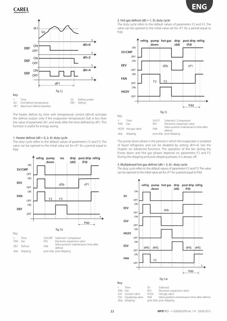
33
ENG
MPXPRO - + 0300055EN rel. 1.4 - 29.09.2015
t
dP1
dt1Sd
OFFDEF
d0=4
d0=2
d0=0
DEF
DEF
ON
OFF
ON
OFF
ON
t
t
t
Fig. 5.j
Key t Time Sd Defrost probe
dt1 End defrost temperature DEF Defrost
dP1 Maximum defrost duration
The heater defrost by time with temperature control (d0=4) activates
the defrost output only if the evaporator temperature (Sd) is less than
the value of parameter dt1, and ends after the time defi ned by dP1. This
function is useful for energy saving.
1. Heater defrost (d0 = 0, 2, 4): duty cycle The duty cycle refers to the default values of parameters F2 and F3. The
valve can be opened to the initial value set for cP1 for a period equal to
Pdd.
t
Pdd
cP1
F3F2
OFF
SV/CMP
EEV
FAN
DEF
refrig refrigpump
down
drip
(dd)
post drip
(Fd)
res
ON
OFF
ON
OFF
ON
OFF
ON
dSb
Fig. 5.k
Key
t Time SV/CMP Solenoid / compressor
FAN Fan EEV Electronic expansion valve
DEF Defrost PddValve position maintenance time after
defrost
drip dripping post drip post dripping
2. Hot gas defrost (d0 = 1, 3): duty cycle The duty cycle refers to the default values of parameters F2 and F3. The
valve can be opened to the initial value set for cP1 for a period equal to
Pdd.
Pdd
cP1
F3F2
OFF
SV/CMP
EEV
FAN
HGSV
refrig refrigpump
down
drip
(dd)
post drip
(Fd)
hot gas
ON
OFF
ON
OFF
ON
OFF
ON
dSb
Fig. 5.l
Key
t Time SV/CP Solenoid / Compressor
FAN Fan EEV Electronic expansion valve
HGSV Hot gas valve PddValve position maintenance time after
defrost
drip dripping post drip post dripping
The pump down phase is the period in which the evaporator is emptied
of liquid refrigerant, and can be disabled by setting dH1=0. See the
chapter on Advanced functions. The operation of the fan during the
Pump down and Hot gas phases depends on parameters F2 and F3.
During the dripping and post-dripping phases, it is always off .
3. Multiplexed hot gas defrost (d0 = 5, 6) : duty cycle The duty cycle refers to the default values of parameters F2 and F3. The valve
can be opened to the initial value set for cP1 for a period equal to Pdd.
t
F2
dHGdHG dHG dHG
FAN
ESV
SSV
EEV
SV
HGSV
refrig refrigpump
down
drip
(dd)
post drip
(Fd)
hot gas
OFF
ON
OFF
ON
OFF
ON
OFF
ON
OFF
ON
OFF
ON
Pdd
dSb
Fig. 5.m
Keyt Time SV Solenoid
FAN Fan EEV Electronic expansion valve
SSV Suction valve HGSV Hot gas valve
ESV Equalizing valve Pdd Valve position maintenance time after defrost
drip dripping post drip post dripping
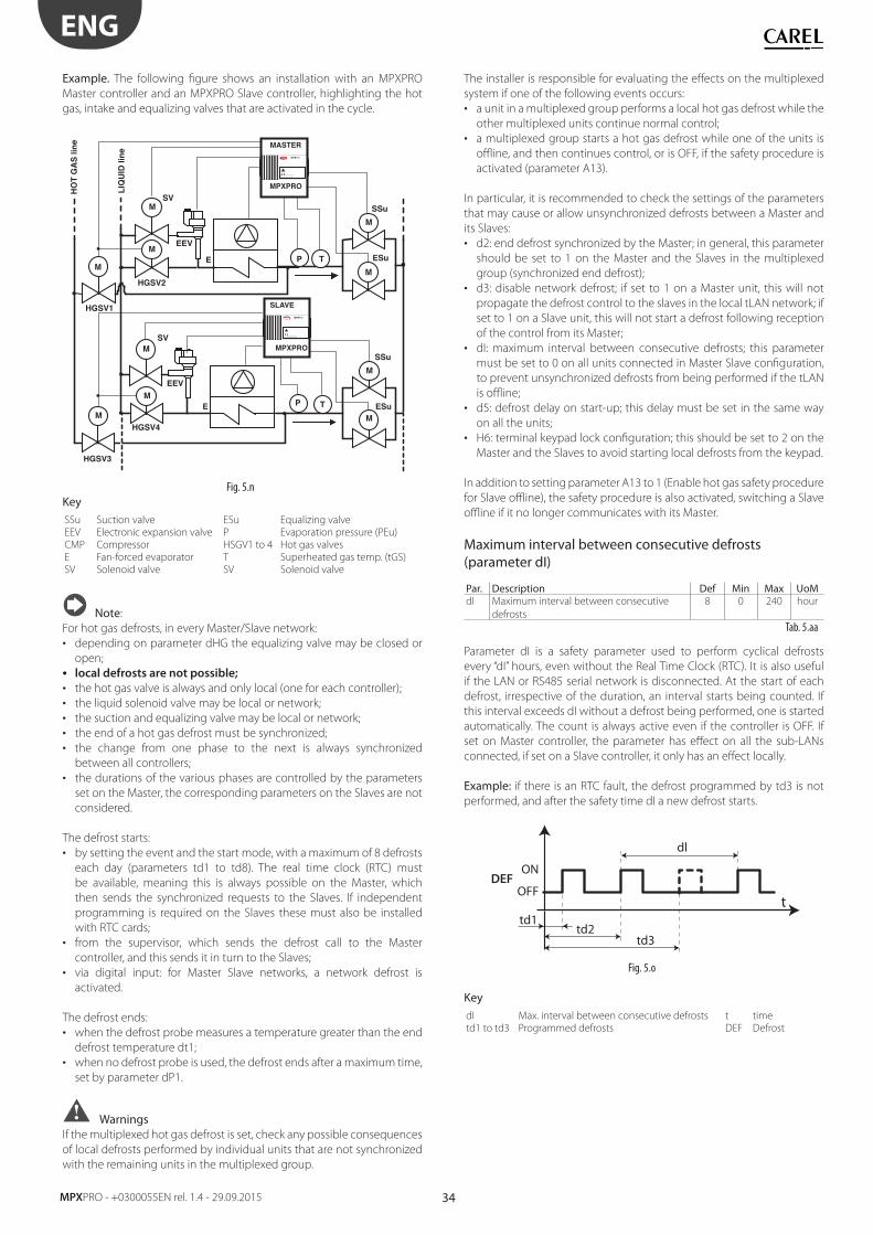
34
ENG
MPXPRO - +0300055EN rel. 1.4 - 29.09.2015
Example. The following fi gure shows an installation with an MPXPRO
Master controller and an MPXPRO Slave controller, highlighting the hot
gas, intake and equalizing valves that are activated in the cycle.
TPE
EEV
MPXPROCAREL
!
MASTER
TP
MPXPROCAREL
!
SLAVE
M
MPXPRO
MPXPRO
E
EEV
M
SV
M
M
SSu
ESu
M
HGSV1
HO
T G
AS
lin
e
LIQ
UID
lin
e
M
HGSV3
M
HGSV2
SVM
HGSV4
SV
SV
M
M
SSu
ESu
Fig. 5.n
KeySSu Suction valve ESu Equalizing valve
EEV Electronic expansion valve P Evaporation pressure (PEu)
CMP Compressor HSGV1 to 4 Hot gas valves
E Fan-forced evaporator T Superheated gas temp. (tGS)
SV Solenoid valve SV Solenoid valve
Note:
For hot gas defrosts, in every Master/Slave network:
• depending on parameter dHG the equalizing valve may be closed or
open;
• local defrosts are not possible;
• the hot gas valve is always and only local (one for each controller);
• the liquid solenoid valve may be local or network;
• the suction and equalizing valve may be local or network;
• the end of a hot gas defrost must be synchronized;
• the change from one phase to the next is always synchronized
between all controllers;
• the durations of the various phases are controlled by the parameters
set on the Master, the corresponding parameters on the Slaves are not
considered.
The defrost starts:
• by setting the event and the start mode, with a maximum of 8 defrosts
each day (parameters td1 to td8). The real time clock (RTC) must
be available, meaning this is always possible on the Master, which
then sends the synchronized requests to the Slaves. If independent
programming is required on the Slaves these must also be installed
with RTC cards;
• from the supervisor, which sends the defrost call to the Master
controller, and this sends it in turn to the Slaves;
• via digital input: for Master Slave networks, a network defrost is
activated.
The defrost ends:
• when the defrost probe measures a temperature greater than the end
defrost temperature dt1;
• when no defrost probe is used, the defrost ends after a maximum time,
set by parameter dP1.
WarningsIf the multiplexed hot gas defrost is set, check any possible consequences
of local defrosts performed by individual units that are not synchronized
with the remaining units in the multiplexed group.
The installer is responsible for evaluating the eff ects on the multiplexed
system if one of the following events occurs:
• a unit in a multiplexed group performs a local hot gas defrost while the
other multiplexed units continue normal control;
• a multiplexed group starts a hot gas defrost while one of the units is
offl ine, and then continues control, or is OFF, if the safety procedure is
activated (parameter A13).
In particular, it is recommended to check the settings of the parameters
that may cause or allow unsynchronized defrosts between a Master and
its Slaves:
• d2: end defrost synchronized by the Master; in general, this parameter
should be set to 1 on the Master and the Slaves in the multiplexed
group (synchronized end defrost);
• d3: disable network defrost; if set to 1 on a Master unit, this will not
propagate the defrost control to the slaves in the local tLAN network; if
set to 1 on a Slave unit, this will not start a defrost following reception
of the control from its Master;
• dI: maximum interval between consecutive defrosts; this parameter
must be set to 0 on all units connected in Master Slave confi guration,
to prevent unsynchronized defrosts from being performed if the tLAN
is offl ine;
• d5: defrost delay on start-up; this delay must be set in the same way
on all the units;
• H6: terminal keypad lock confi guration; this should be set to 2 on the
Master and the Slaves to avoid starting local defrosts from the keypad.
In addition to setting parameter A13 to 1 (Enable hot gas safety procedure
for Slave offl ine), the safety procedure is also activated, switching a Slave
offl ine if it no longer communicates with its Master.
Maximum interval between consecutive defrosts (parameter dI)
Par. Description Def Min Max UoMdI Maximum interval between consecutive
defrosts
8 0 240 hour
Tab. 5.aa
Parameter dI is a safety parameter used to perform cyclical defrosts
every “dI” hours, even without the Real Time Clock (RTC). It is also useful
if the LAN or RS485 serial network is disconnected. At the start of each
defrost, irrespective of the duration, an interval starts being counted. If
this interval exceeds dI without a defrost being performed, one is started
automatically. The count is always active even if the controller is OFF. If
set on Master controller, the parameter has eff ect on all the sub-LANs
connected, if set on a Slave controller, it only has an eff ect locally.
Example: if there is an RTC fault, the defrost programmed by td3 is not
performed, and after the safety time dI a new defrost starts.
ttd1
DEFON
OFF
td2td3
dl
Fig. 5.o
KeydI Max. interval between consecutive defrosts t time
td1 to td3 Programmed defrosts DEF Defrost
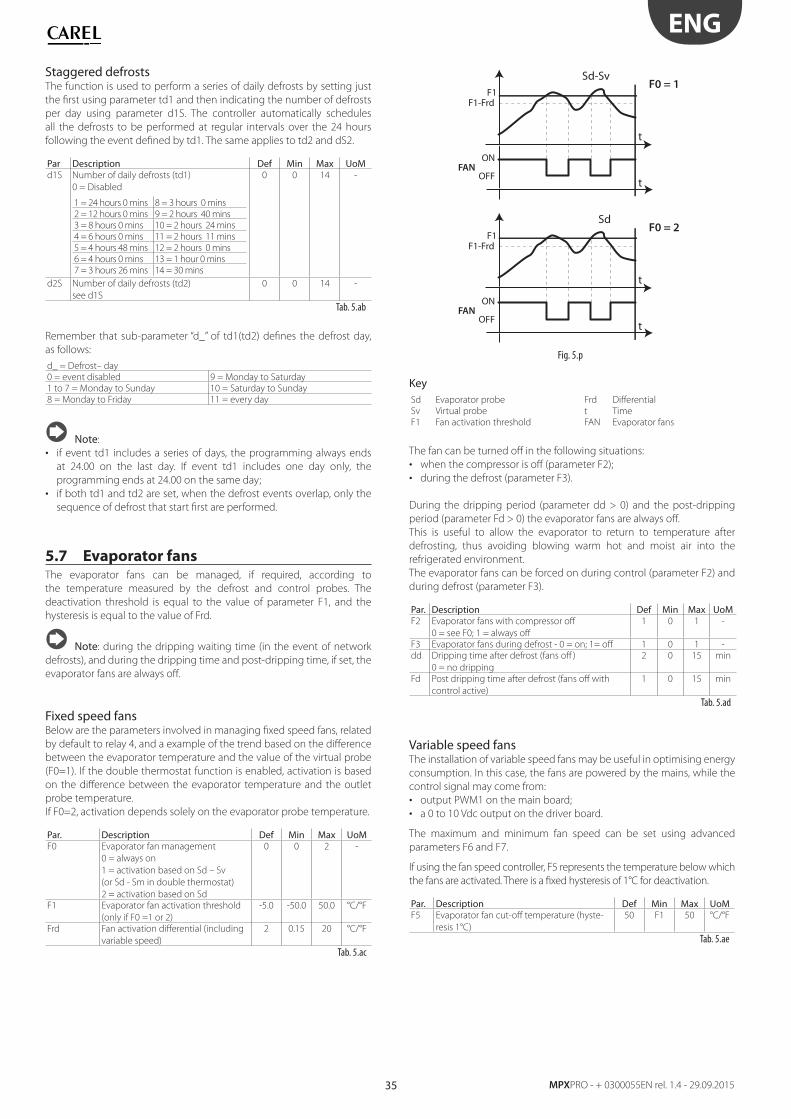
35
ENG
MPXPRO - + 0300055EN rel. 1.4 - 29.09.2015
Staggered defrostsThe function is used to perform a series of daily defrosts by setting just
the fi rst using parameter td1 and then indicating the number of defrosts
per day using parameter d1S. The controller automatically schedules
all the defrosts to be performed at regular intervals over the 24 hours
following the event defi ned by td1. The same applies to td2 and dS2.
Par Description Def Min Max UoMd1S Number of daily defrosts (td1)
0 = Disabled
1 = 24 hours 0 mins 8 = 3 hours 0 mins
2 = 12 hours 0 mins 9 = 2 hours 40 mins
3 = 8 hours 0 mins 10 = 2 hours 24 mins
4 = 6 hours 0 mins 11 = 2 hours 11 mins
5 = 4 hours 48 mins 12 = 2 hours 0 mins
6 = 4 hours 0 mins 13 = 1 hour 0 mins
7 = 3 hours 26 mins 14 = 30 mins
0 0 14 -
d2S Number of daily defrosts (td2)
see d1S
0 0 14 -
Tab. 5.ab
Remember that sub-parameter “d_” of td1(td2) defi nes the defrost day,
as follows:
d_ = Defrost– day
0 = event disabled 9 = Monday to Saturday
1 to 7 = Monday to Sunday 10 = Saturday to Sunday
8 = Monday to Friday 11 = every day
Note:
• if event td1 includes a series of days, the programming always ends
at 24.00 on the last day. If event td1 includes one day only, the
programming ends at 24.00 on the same day;
• if both td1 and td2 are set, when the defrost events overlap, only the
sequence of defrost that start fi rst are performed.
5.7 Evaporator fansThe evaporator fans can be managed, if required, according to
the temperature measured by the defrost and control probes. The
deactivation threshold is equal to the value of parameter F1, and the
hysteresis is equal to the value of Frd.
Note: during the dripping waiting time (in the event of network
defrosts), and during the dripping time and post-dripping time, if set, the
evaporator fans are always off .
Fixed speed fansBelow are the parameters involved in managing fi xed speed fans, related
by default to relay 4, and a example of the trend based on the diff erence
between the evaporator temperature and the value of the virtual probe
(F0=1). If the double thermostat function is enabled, activation is based
on the diff erence between the evaporator temperature and the outlet
probe temperature.
If F0=2, activation depends solely on the evaporator probe temperature.
Par. Description Def Min Max UoMF0 Evaporator fan management
0 = always on
1 = activation based on Sd – Sv
(or Sd - Sm in double thermostat)
2 = activation based on Sd
0 0 2 -
F1 Evaporator fan activation threshold
(only if F0 =1 or 2)
-5.0 -50.0 50.0 °C/°F
Frd Fan activation diff erential (including
variable speed)
2 0.15 20 °C/°F
Tab. 5.ac
Sd-Sv
t
t
F0 = 1F1
F1-Frd
ON
OFFFAN
Sd
t
t
F0 = 2F1
F1-Frd
ON
OFFFAN
Fig. 5.p
KeySd Evaporator probe Frd Diff erential
Sv Virtual probe t Time
F1 Fan activation threshold FAN Evaporator fans
The fan can be turned off in the following situations:
• when the compressor is off (parameter F2);
• during the defrost (parameter F3).
During the dripping period (parameter dd > 0) and the post-dripping
period (parameter Fd > 0) the evaporator fans are always off .
This is useful to allow the evaporator to return to temperature after
defrosting, thus avoiding blowing warm hot and moist air into the
refrigerated environment.
The evaporator fans can be forced on during control (parameter F2) and
during defrost (parameter F3).
Par. Description Def Min Max UoMF2 Evaporator fans with compressor off
0 = see F0; 1 = always off
1 0 1 -
F3 Evaporator fans during defrost - 0 = on; 1= off 1 0 1 -
dd Dripping time after defrost (fans off )
0 = no dripping
2 0 15 min
Fd Post dripping time after defrost (fans off with
control active)
1 0 15 min
Tab. 5.ad
Variable speed fansThe installation of variable speed fans may be useful in optimising energy
consumption. In this case, the fans are powered by the mains, while the
control signal may come from:
• output PWM1 on the main board;
• a 0 to 10 Vdc output on the driver board.
The maximum and minimum fan speed can be set using advanced
parameters F6 and F7.
If using the fan speed controller, F5 represents the temperature below which
the fans are activated. There is a fi xed hysteresis of 1°C for deactivation.
Par. Description Def Min Max UoMF5 Evaporator fan cut-off temperature (hyste-
resis 1°C)
50 F1 50 °C/°F
Tab. 5.ae
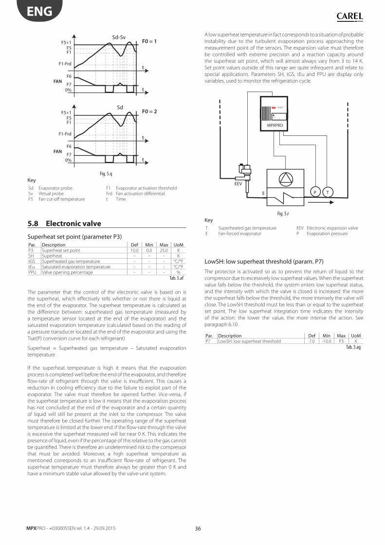
36
ENG
MPXPRO - +0300055EN rel. 1.4 - 29.09.2015
t
t
Sd-SvF0 = 1F5+1
F5F1
F1-Frd
F6FAN
F70%
t
t
SdF0 = 2F5+1
F5F1
F1-Frd
F6FAN
F70%
Fig. 5.q
KeySd Evaporator probe F1 Evaporator activation threshold
Sv Virtual probe Frd Fan activation diff erential
F5 Fan cut-off temperature t Time
5.8 Electronic valve
Superheat set point (parameter P3)Par. Description Def Min Max UoMP3 Superheat set point 10.0 0.0 25.0 K
SH Superheat - - - K
tGS Superheated gas temperature - - - °C/°F
tEu Saturated evaporation temperature - - - °C/°F
PPU Valve opening percentage - - - %
Tab. 5.af
The parameter that the control of the electronic valve is based on is
the superheat, which eff ectively tells whether or not there is liquid at
the end of the evaporator. The superheat temperature is calculated as
the diff erence between: superheated gas temperature (measured by
a temperature sensor located at the end of the evaporator) and the
saturated evaporation temperature (calculated based on the reading of
a pressure transducer located at the end of the evaporator and using the
Tsat(P) conversion curve for each refrigerant)
Superheat = Superheated gas temperature – Saturated evaporation
temperature
If the superheat temperature is high it means that the evaporation
process is completed well before the end of the evaporator, and therefore
fl ow-rate of refrigerant through the valve is insuffi cient. This causes a
reduction in cooling effi ciency due to the failure to exploit part of the
evaporator. The valve must therefore be opened further. Vice-versa, if
the superheat temperature is low it means that the evaporation process
has not concluded at the end of the evaporator and a certain quantity
of liquid will still be present at the inlet to the compressor. The valve
must therefore be closed further. The operating range of the superheat
temperature is limited at the lower end: if the fl ow-rate through the valve
is excessive the superheat measured will be near 0 K. This indicates the
presence of liquid, even if the percentage of this relative to the gas cannot
be quantifi ed. There is therefore an undetermined risk to the compressor
that must be avoided. Moreover, a high superheat temperature as
mentioned corresponds to an insuffi cient fl ow-rate of refrigerant. The
superheat temperature must therefore always be greater than 0 K and
have a minimum stable value allowed by the valve-unit system.
A low superheat temperature in fact corresponds to a situation of probable
instability due to the turbulent evaporation process approaching the
measurement point of the sensors. The expansion valve must therefore
be controlled with extreme precision and a reaction capacity around
the superheat set point, which will almost always vary from 3 to 14 K.
Set point values outside of this range are quite infrequent and relate to
special applications. Parameters SH, tGS, tEu and PPU are display only
variables, used to monitor the refrigeration cycle.
TP
EEV
MPXPROCAREL
!
MPXPRO
E
Fig. 5.r
KeyT Superheated gas temperature EEV Electronic expansion valve
E Fan-forced evaporator P Evaporation pressure
LowSH: low superheat threshold (param. P7)
The protector is activated so as to prevent the return of liquid to the
compressor due to excessively low superheat values. When the superheat
value falls below the threshold, the system enters low superheat status,
and the intensity with which the valve is closed is increased: the more
the superheat falls below the threshold, the more intensely the valve will
close. The LowSH threshold must be less than or equal to the superheat
set point. The low superheat integration time indicates the intensity
of the action: the lower the value, the more intense the action. See
paragraph 6.10.
Par. Description Def Min Max UoMP7 LowSH: low superheat threshold 7.0 -10.0 P3 K
Tab. 5.ag
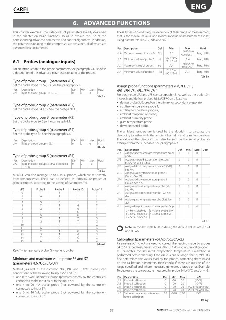
37
ENG
MPXPRO - + 0300055EN rel. 1.4 - 29.09.2015
6. ADVANCED FUNCTIONS
This chapter examines the categories of parameters already described
in the chapter on basic functions, so as to explain the use of the
corresponding advanced parameters and control algorithms. In addition,
the parameters relating to the compressor are explained, all of which are
advanced level parameters.
6.1 Probes (analogue inputs)
For an introduction to the probe parameters, see paragraph 5.1. Below is
a description of the advanced parameters relating to the probes.
Type of probe, group 1 (parameter /P1)Set the probes type S1, S2, S3. See the paragraph 5.1.
Par. Description Def Min Max UoM
/P1 Type of probe, group 1 (S1…S3) 0 0 3 -
Tab. 6.a
Type of probe, group 2 (parameter /P2)Set the probes type S4 e S5. See the paragraph 4.3.
Type of probe, group 3 (parameter /P3)Set the probe type S6. See the paragraph 4.3.
Type of probe, group 4 (parameter /P4)Set the probe type S7. See the paragraph 5.1.
Par. Description Def Min Max UoM
/P4 Type of probe, group 4 (S7) 0 0 6 -
Tab. 6.b
Type of probe, group 5 (parameter /P5)Par. Description Def Min Max UoM
/P5 Type of probe, group 5 : serial probes (S8
to S11)
0 0 15 -
Tab. 6.c
MPXPRO can also manage up to 4 serial probes, which are set directly
from the supervisor. These can be defi ned as temperature probes or
generic probes, according to the setting of parameter /P5.
/P5 Probe 8 Probe 9 Probe 10 Probe 110 T T T T
1 G T T T
2 T G T T
3 G G T T
4 T T G T
5 G T G T
6 T G G T
7 G G G T
8 T T T G
9 G T T G
10 T G T G
11 G G T G
12 T T G G
13 G T G G
14 T G G G
15 G G G G
Tab. 6.d
Key: T = temperature probe, G = generic probe
Minimum and maximum value probe S6 and S7 (parameters /L6,/U6,/L7,/U7)
MPXPRO, as well as the common NTC, PTC and PT1000 probes, can
connect one of the following to inputs S6 and S7:
• one 0 to 5Vdc ratiometric probe (powered directly by the controller),
connected to the input S6 or to the input S7;
• one 4 to 20 mA active probe (not powered by the controller),
connected to input S7;
• one 0 to 10 Vdc active probe (not powered by the controller),
connected to input S7.
These types of probes require defi nition of their range of measurement,
that is, the maximum value and minimum value of measurement are set,
using parameters /L6, /L7, /U6 and /U7.
Par. Description Def Min Max UoM
/U6 Maximum value of probe 6 9.3 /L6160 if /5=0
999 if /5=1barg, RH%
/L6 Minimum value of probe 6 -1-20 if /5=0
-90 if /5=1/U6 barg, RH%
/U7 Maximum value of probe 7 9.3 /L7160 if /5=0
999 if /5=1barg, RH%
/L7 Minimum value of probe 7 -1.0-20 if /5=0
-90 if /5=1/U7 barg, RH%
Tab. 6.e
Assign probe functions (parameters /Fd, /FE, /FF, /FG, /FH, /FI, /FL, /FM, /Fn)For parameters /Fd and /FE see paragraph 4.3. As well as the outlet Sm,
intake Sr and defrost probes Sd, MPXPRO also features:
• defrost probe Sd2, used on the primary or secondary evaporator;
• auxiliary temperature probe 1;
• auxiliary temperature probe 2;
• ambient temperature probe;
• ambient humidity probe;
• glass temperature probe;
• dewpoint serial probe.
The ambient temperature is used by the algorithm to calculate the
dewpoint, together with the ambient humidity and glass temperature.
The value of the dewpoint can also be sent by the serial probe, for
example from the supervisor. See paragraph 6.3.
Par. Description Def Min Max UoM/Fd Assign superheated gas temperature probe
(tGS)
0 0 11
/FE Assign saturated evaporation pressure/
temperature (PEu/tEu)
0 0 11
/FF Assign defrost temperature probe 2 (Sd2)
See /FA
0 0 11
/FG Assign auxiliary temperature probe 1
(Saux1) See /FA
0 0 11
/FH Assign auxiliary temperature probe 2
(Saux2) See /FA
0 0 11
/FI Assign ambient temperature probe (SA)
See /FA
0 0 11
/FL Assign ambient humidity probe (SU) See
/FA
0 0 11
/FM Assign glass temperature probe (Svt) See
/FA
0 0 11
/Fn Assign dewpoint value to serial probe (Sdp)
0 = Func. disabled 3 = Serial probe S10
1 = Serial probe S8 4 = Serial probe S11
2 = Serial probe S9
0 0 4
Tab. 6.f
Note: in models with built-in driver, the default values are /Fd=4
and /FE=6.
Calibration (parameters /c4,/c5,/c6,/c7,/cE)Parameters /c4 to /c7 are used to correct the reading made by probes
S4 to S7 respectively. Serial probes S8 to S11 do not require calibration.
/cE calibrates the saturated evaporation temperature. Calibration is
performed before checking if the value is out-of-range, that is, MPXPRO
fi rst determines the values read by the probes, correcting them based
on the calibration parameters, then checks if these are outside of the
range specifi ed and where necessary generates a probe error. Example:
To decrease the temperature measured by probe S4 by 3°C, set /c4 = -3.
Par. Description Def Min Max UoM/c4 Probe 4 calibration 0 -20 20 (°C/°F)
/c5 Probe 5 calibration 0 -20 20 (°C/°F)
/c6 Probe 6 calibration 0 -20 20 (°C/°F/barg/ RH%)
/c7 Probe 7 calibration 0 -20 20 (°C/°F/barg/ RH%)
/cE Saturated evaporation tempe-
rature calibration
0.0 -20.0 20.0 °C/°F
Tab. 6.g
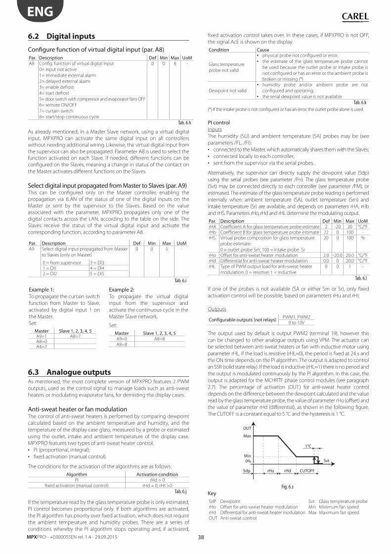
38
ENG
MPXPRO - +0300055EN rel. 1.4 - 29.09.2015
6.2 Digital inputs
Confi gure function of virtual digital input (par. A8)Par. Description Def Min Max UoMA8 Confi g. function of virtual digital input
0= input not active
1= immediate external alarm
2= delayed external alarm
3= enable defrost
4= start defrost
5= door switch with compressor and evaporator fans OFF
6= remote ON/OFF
7= curtain switch
8= start/stop continuous cycle
0 0 8 -
Tab. 6.h
As already mentioned, in a Master Slave network, using a virtual digital
input, MPXPRO can activate the same digital input on all controllers
without needing additional wiring. Likewise, the virtual digital input from
the supervisor can also be propagated. Parameter A8 is used to select the
function activated on each Slave. If needed, diff erent functions can be
confi gured on the Slaves, meaning a change in status of the contact on
the Master activates diff erent functions on the Slaves.
Select digital input propagated from Master to Slaves (par. A9)This can be confi gured only on the Master controller, enabling the
propagation via tLAN of the status of one of the digital inputs on the
Master or sent by the supervisor to the Slaves. Based on the value
associated with the parameter, MPXPRO propagates only one of the
digital contacts across the LAN, according to the table on the side. The
Slaves receive the status of the virtual digital input and activate the
corresponding function, according to parameter A8.
Par. Description Def Min Max UoMA9 Select digital input propagated from Master
to Slaves (only on Master)
0 = from supervisor 3 = DI3
1 = DI1 4 = DI4
2 = DI2 5 = DI5
0 0 5 -
Tab. 6.i
Example 1:To propagate the curtain switch
function from Master to Slave,
activated by digital input 1 on
the Master.
Example 2:To propagate the virtual digital
input from the supervisor and
activate the continuous cycle in the
Master Slave network.
Set:
Master Slave 1, 2, 3, 4, 5A9=1 A8=7A8=0A4=7
Set:
Master Slave 1, 2, 3, 4, 5A9=0 A8=8
A8=8
6.3 Analogue outputsAs mentioned, the most complete version of MPXPRO features 2 PWM
outputs, used as the control signal to manage loads such as anti-sweat
heaters or modulating evaporator fans, for demisting the display cases.
Anti-sweat heater or fan modulationThe control of anti-sweat heaters is performed by comparing dewpoint
calculated based on the ambient temperature and humidity, and the
temperature of the display case glass, measured by a probe or estimated
using the outlet, intake and ambient temperature of the display case.
MPXPRO features two types of anti-sweat heater control:
• PI (proportional, integral);
• fi xed activation (manual control).
The conditions for the activation of the algorithms are as follows:
Algorithm Activation conditionPI rHd > 0
fi xed activation (manual control) rHd = 0; rHt >0
Tab. 6.j
If the temperature read by the glass temperature probe is only estimated,
PI control becomes proportional only. If both algorithms are activated,
the PI algorithm has priority over fi xed activation, which does not require
the ambient temperature and humidity probes. There are a series of
conditions whereby the PI algorithm stops operating and, if activated,
fi xed activation control takes over. In these cases, if MPXPRO is not OFF,
the signal AcE is shown on the display.
Condition Cause
Glass temperature
probe not valid
• physical probe not confi gured or error;
• the estimate of the glass temperature probe cannot
be used because the outlet probe or intake probe is
not confi gured or has an error or the ambient probe is
broken or missing (*)
Dewpoint not valid
• humidity probe and/or ambient probe are not
confi gured and operating;
• the serial dewpoint value is not available
Tab. 6.k
(*) If the intake probe is not confi gured or has an error, the outlet probe alone is used.
PI controlInputs
The humidity (SU) and ambient temperature (SA) probes may be (see
parameters /FL, /FI):
• connected to the Master, which automatically shares them with the Slaves;
• connected locally to each controller;
• sent from the supervisor via the serial probes.
Alternatively, the supervisor can directly supply the dewpoint value (Sdp)
using the serial probes (see parameter /Fn). The glass temperature probe
(Svt) may be connected directly to each controller (see parameter /FM), or
estimated. The estimate of the glass temperature probe reading is performed
internally when: ambient temperature (SA), outlet temperature (Sm) and
intake temperature (Sr) are available, and depends on parameters rHA, rHb
and rHS. Parameters rHo, rHd and rHL determine the modulating output.
Par. Description Def Min Max UoMrHA Coeffi cient A for glass temperature probe estimate 2 -20 20 °C/°F
rHb Coeffi cient B for glass temperature probe estimate 22 0 100 -
rHS Virtual probe composition for glass temperature
probe estimate:
0 = outlet probe Sm; 100 = intake probe Sr
20 0 100 %
rHo Off set for anti-sweat heater modulation 2.0 -20.0 20.0 °C/°F
rHd Diff erential for anti-sweat heater modulation 0.0 0 20.0 °C/°F
rHL Type of PWM output load for anti-sweat heater
modulation: 0 = resistive; 1 = inductive
0 0 1 -
Tab. 6.l
If one of the probes is not available (SA or either Sm or Sr), only fi xed
activation control will be possible, based on parameters rHu and rHt.
Outputs
Confi gurable outputs (not relays) PWM1, PWM2
0 to 10V
The output used by default is output PWM2 (terminal 19), however this
can be changed to other analogue outputs using VPM. The actuator can
be selected between anti-sweat heaters or fan with inductive motor using
parameter rHL. If the load is resistive (rHL=0), the period is fi xed at 24 s and
the ON time depends on the PI algorithm. The output is adapted to control
an SSR (solid state relay). If the load is inductive (rHL=1) there is no period and
the output is modulated continuously by the PI algorithm. In this case, the
output is adapted for the MCHRTF phase control modules (see paragraph
2.7). The percentage of activation (OUT) for anti-sweat heater control
depends on the diff erence between the dewpoint calculated and the value
read by the glass temperature probe, the value of parameter rHo (off set) and
the value of parameter rHd (diff erential), as shown in the following fi gure.
The CUTOFF is a constant equal to 5 °C and the hysteresis is 1 °C.
Svt
OUT
Sdp rHo rHd
1°C
CUTOFF
0%
Max
Min
Fig. 6.s
KeySdP Dewpoint Svt Glass temperature probe
rHo Off set for anti-sweat heater modulation Min Minimum fan speed
rHd Diff erential for anti-sweat heater modulation Max Maximum fan speed
OUT Anti-sweat control
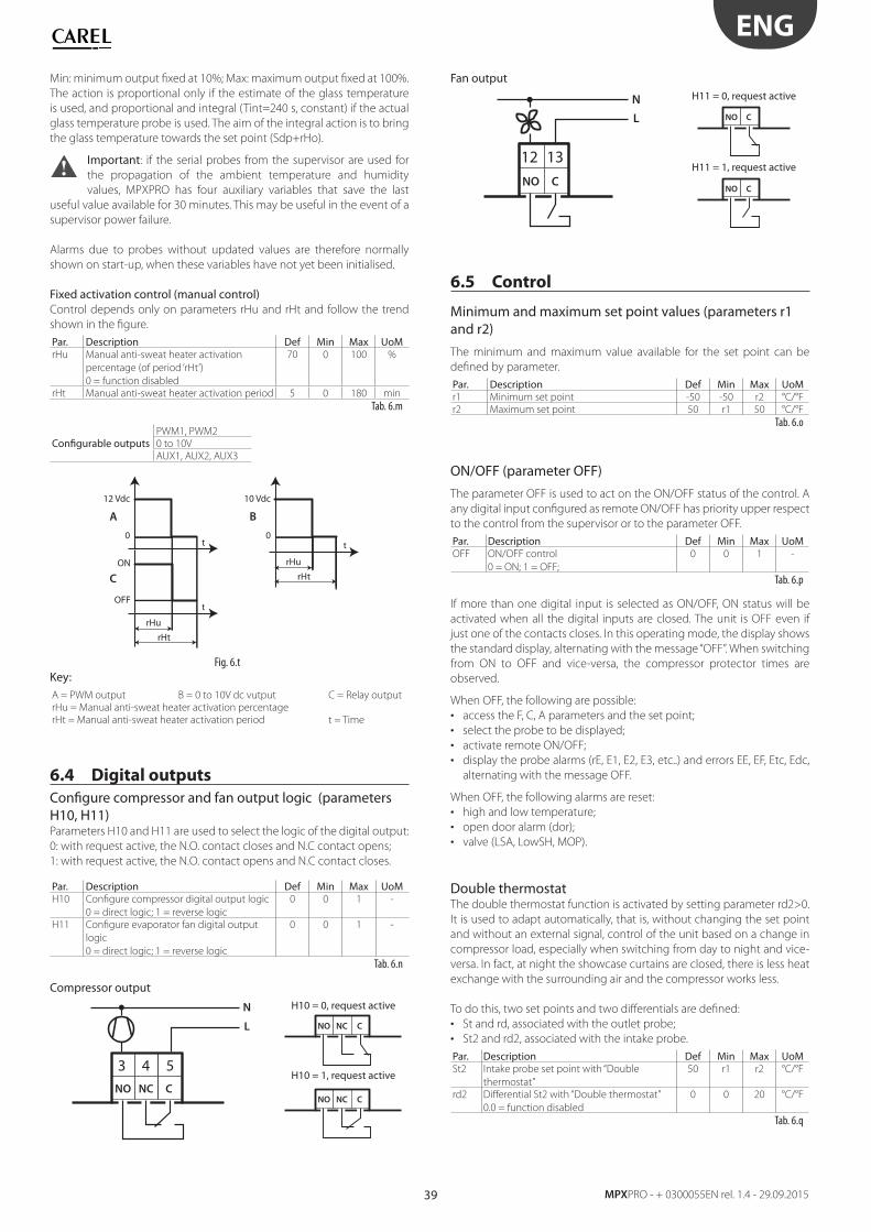
39
ENG
MPXPRO - + 0300055EN rel. 1.4 - 29.09.2015
Min: minimum output fi xed at 10%; Max: maximum output fi xed at 100%.
The action is proportional only if the estimate of the glass temperature
is used, and proportional and integral (Tint=240 s, constant) if the actual
glass temperature probe is used. The aim of the integral action is to bring
the glass temperature towards the set point (Sdp+rHo).
Important: if the serial probes from the supervisor are used for
the propagation of the ambient temperature and humidity
values, MPXPRO has four auxiliary variables that save the last
useful value available for 30 minutes. This may be useful in the event of a
supervisor power failure.
Alarms due to probes without updated values are therefore normally
shown on start-up, when these variables have not yet been initialised.
Fixed activation control (manual control)Control depends only on parameters rHu and rHt and follow the trend
shown in the fi gure.
Par. Description Def Min Max UoMrHu Manual anti-sweat heater activation
percentage (of period ‘rHt’)
0 = function disabled
70 0 100 %
rHt Manual anti-sweat heater activation period 5 0 180 min
Tab. 6.m
Confi gurable outputsPWM1, PWM2
0 to 10V
AUX1, AUX2, AUX3
rHu
t
t t
rHt
rHu
0
BA
C
10 Vdc
0
12 Vdc
OFF
ONrHt
Fig. 6.t
Key:A = PWM output B = 0 to 10V dc vutput C = Relay output
rHu = Manual anti-sweat heater activation percentage
rHt = Manual anti-sweat heater activation period t = Time
6.4 Digital outputs
Confi gure compressor and fan output logic (parameters H10, H11)Parameters H10 and H11 are used to select the logic of the digital output:
0: with request active, the N.O. contact closes and N.C contact opens;
1: with request active, the N.O. contact opens and N.C contact closes.
Par. Description Def Min Max UoMH10 Confi gure compressor digital output logic
0 = direct logic; 1 = reverse logic
0 0 1 -
H11 Confi gure evaporator fan digital output
logic
0 = direct logic; 1 = reverse logic
0 0 1 -
Tab. 6.n
Compressor output
NO NC C
L
N
43 5
H10 = 0, request active
NO NC C
H10 = 1, request active
NO NC C
Fan output
NO C
L
N
12 13
H11 = 0, request active
NO C
H11 = 1, request active
NO C
6.5 Control
Minimum and maximum set point values (parameters r1 and r2)
The minimum and maximum value available for the set point can be
defi ned by parameter.
Par. Description Def Min Max UoMr1 Minimum set point -50 -50 r2 °C/°F
r2 Maximum set point 50 r1 50 °C/°F
Tab. 6.o
ON/OFF (parameter OFF)
The parameter OFF is used to act on the ON/OFF status of the control. A
any digital input confi gured as remote ON/OFF has priority upper respect
to the control from the supervisor or to the parameter OFF.
Par. Description Def Min Max UoMOFF ON/OFF control
0 = ON; 1 = OFF;
0 0 1 -
Tab. 6.p
If more than one digital input is selected as ON/OFF, ON status will be
activated when all the digital inputs are closed. The unit is OFF even if
just one of the contacts closes. In this operating mode, the display shows
the standard display, alternating with the message “OFF”. When switching
from ON to OFF and vice-versa, the compressor protector times are
observed.
When OFF, the following are possible:
• access the F, C, A parameters and the set point;
• select the probe to be displayed;
• activate remote ON/OFF;
• display the probe alarms (rE, E1, E2, E3, etc..) and errors EE, EF, Etc, Edc,
alternating with the message OFF.
When OFF, the following alarms are reset:
• high and low temperature;
• open door alarm (dor);
• valve (LSA, LowSH, MOP).
Double thermostatThe double thermostat function is activated by setting parameter rd2>0.
It is used to adapt automatically, that is, without changing the set point
and without an external signal, control of the unit based on a change in
compressor load, especially when switching from day to night and vice-
versa. In fact, at night the showcase curtains are closed, there is less heat
exchange with the surrounding air and the compressor works less.
To do this, two set points and two diff erentials are defi ned:
• St and rd, associated with the outlet probe;
• St2 and rd2, associated with the intake probe.
Par. Description Def Min Max UoMSt2 Intake probe set point with “Double
thermostat”
50 r1 r2 °C/°F
rd2 Diff erential St2 with “Double thermostat”
0.0 = function disabled
0 0 20 °C/°F
Tab. 6.q
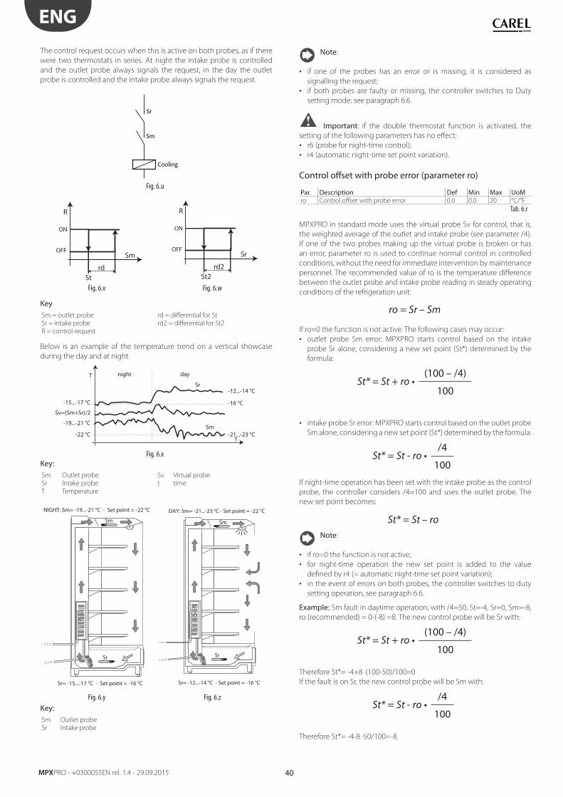
40
ENG
MPXPRO - +0300055EN rel. 1.4 - 29.09.2015
The control request occurs when this is active on both probes, as if there
were two thermostats in series. At night the intake probe is controlled
and the outlet probe always signals the request, in the day the outlet
probe is controlled and the intake probe always signals the request.
Sr
Sm
Cooling
Fig. 6.u
Sm
rdSt
ON
R
OFF Sr
rd2St2
ON
R
OFF
Fig. 6.v Fig. 6.w
Key Sm = outlet probe rd = diff erential for St
Sr = intake probe rd2 = diff erential for St2
R = control request
Below is an example of the temperature trend on a vertical showcase
during the day and at night.
night day
Sr
Sm
t
-15...-17 °C
-19...-21 °C
-22 °C -21...-23 °C
-12...-14 °C
-16 °C
Sv=(Sm+Sr)/2
T
Fig. 6.x
Key: Sm Outlet probe Sv Virtual probe
Sr Intake probe t time
T Temperature
NIGHT: Sm= -19...-21 °C - Set point = -22 °C
Sr= -15...-17 °C - Set point = -16 °C
Sm
Sr
DAY: Sm= -21...-23 °C - Set point = -22 °C
Sr= -12...-14 °C - Set point = -16 °C
Sm
Sr
Fig. 6.y Fig. 6.z
Key: Sm Outlet probe
Sr Intake probe
Note:
• if one of the probes has an error or is missing, it is considered as
signalling the request;
• if both probes are faulty or missing, the controller switches to Duty
setting mode: see paragraph 6.6.
Important: if the double thermostat function is activated, the
setting of the following parameters has no eff ect:
• r6 (probe for night-time control);
• r4 (automatic night-time set point variation).
Control off set with probe error (parameter ro)
Par. Description Def Min Max UoMro Control off set with probe error 0.0 0.0 20 °C/°F
Tab. 6.r
MPXPRO in standard mode uses the virtual probe Sv for control, that is,
the weighted average of the outlet and intake probe (see parameter /4).
If one of the two probes making up the virtual probe is broken or has
an error, parameter ro is used to continue normal control in controlled
conditions, without the need for immediate intervention by maintenance
personnel. The recommended value of ro is the temperature diff erence
between the outlet probe and intake probe reading in steady operating
conditions of the refrigeration unit:
ro = Sr – Sm
If ro=0 the function is not active. The following cases may occur:
• outlet probe Sm error: MPXPRO starts control based on the intake
probe Sr alone, considering a new set point (St*) determined by the
formula:
St* = St + ro(100 – /4)
100
• intake probe Sr error: MPXPRO starts control based on the outlet probe
Sm alone, considering a new set point (St*) determined by the formula:
St* = St - ro/4
100
If night-time operation has been set with the intake probe as the control
probe, the controller considers /4=100 and uses the outlet probe. The
new set point becomes:
St* = St – roNote:
• if ro=0 the function is not active;
• for night-time operation the new set point is added to the value
defi ned by r4 (= automatic night-time set point variation);
• in the event of errors on both probes, the controller switches to duty
setting operation, see paragraph 6.6.
Example: Sm fault in daytime operation, with /4=50, St=-4, Sr=0, Sm=-8,
ro (recommended) = 0-(-8) =8. The new control probe will be Sr with:
St* = St + ro(100 – /4)
100
Therefore St*= -4+8 ·(100-50)/100=0
If the fault is on Sr, the new control probe will be Sm with:
St* = St - ro/4
100
Therefore St*= -4-8 ·50/100=-8.
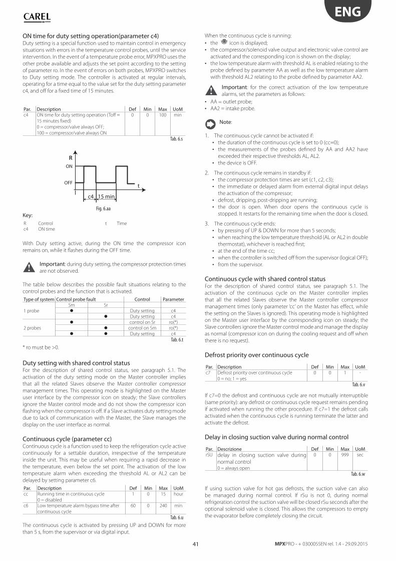
41
ENG
MPXPRO - + 0300055EN rel. 1.4 - 29.09.2015
ON time for duty setting operation(parameter c4)Duty setting is a special function used to maintain control in emergency
situations with errors in the temperature control probes, until the service
intervention. In the event of a temperature probe error, MPXPRO uses the
other probe available and adjusts the set point according to the setting
of parameter ro. In the event of errors on both probes, MPXPRO switches
to Duty setting mode. The controller is activated at regular intervals,
operating for a time equal to the value set for the duty setting parameter
c4, and off for a fi xed time of 15 minutes.
Par. Description Def Min Max UoMc4 ON time for duty setting operation (Toff =
15 minutes fi xed)
0 = compressor/valve always OFF;
100 = compressor/valve always ON
0 0 100 min
Tab. 6.s
c4 15 min
t
ON
R
OFF
Fig. 6.aa
Key: R Control t Time
c4 ON time
With Duty setting active, during the ON time the compressor icon
remains on, while it fl ashes during the OFF time.
Important: during duty setting, the compressor protection times
are not observed.
The table below describes the possible fault situations relating to the
control probes and the function that is activated.
Type of system Control probe fault Control Parameter
1 probe
Sm Sr
Duty setting c4
Duty setting c4
2 probes
control on Sr ro(*)
control on Sm ro(*)
Duty setting c4
Tab. 6.t
* ro must be >0.
Duty setting with shared control statusFor the description of shared control status, see paragraph 5.1. The
activation of the duty setting mode on the Master controller implies
that all the related Slaves observe the Master controller compressor
management times. This operating mode is highlighted on the Master
user interface by the compressor icon on steady; the Slave controllers
ignore the Master control mode and do not show the compressor icon
fl ashing when the compressor is off . If a Slave activates duty setting mode
due to lack of communication with the Master, the Slave manages the
display on the user interface as normal.
Continuous cycle (parameter cc)Continuous cycle is a function used to keep the refrigeration cycle active
continuously for a settable duration, irrespective of the temperature
inside the unit. This may be useful when requiring a rapid decrease in
the temperature, even below the set point. The activation of the low
temperature alarm when exceeding the threshold AL or AL2 can be
delayed by setting parameter c6.
Par. Description Def Min Max UoMcc Running time in continuous cycle
0 = disabled
1 0 15 hour
c6 Low temperature alarm bypass time after
continuous cycle
60 0 240 min
Tab. 6.u
The continuous cycle is activated by pressing UP and DOWN for more
than 5 s, from the supervisor or via digital input.
When the continuous cycle is running:
• the icon is displayed;
• the compressor/solenoid valve output and electronic valve control are
activated and the corresponding icon is shown on the display;
• the low temperature alarm with threshold AL is enabled relating to the
probe defi ned by parameter AA as well as the low temperature alarm
with threshold AL2 relating to the probe defi ned by parameter AA2.
Important: for the correct activation of the low temperature
alarms, set the parameters as follows:
• AA = outlet probe;
• AA2 = intake probe.
Note:
1. The continuous cycle cannot be activated if:
• the duration of the continuous cycle is set to 0 (cc=0);
• the measurements of the probes defi ned by AA and AA2 have
exceeded their respective thresholds AL, AL2.
• the device is OFF.
2. The continuous cycle remains in standby if:
• the compressor protection times are set (c1, c2, c3);
• the immediate or delayed alarm from external digital input delays
the activation of the compressor;
• defrost, dripping, post-dripping are running;
• the door is open. When door opens the continuous cycle is
stopped. It restarts for the remaining time when the door is closed.
3. The continuous cycle ends:
• by pressing of UP & DOWN for more than 5 seconds;
• when reaching the low temperature threshold (AL or AL2 in double
thermostat), whichever is reached fi rst;
• at the end of the time cc;
• when the controller is switched off from the supervisor (logical OFF);
• from the supervisor.
Continuous cycle with shared control statusFor the description of shared control status, see paragraph 5.1. The
activation of the continuous cycle on the Master controller implies
that all the related Slaves observe the Master controller compressor
management times (only parameter ‘cc’ on the Master has eff ect, while
the setting on the Slaves is ignored). This operating mode is highlighted
on the Master user interface by the corresponding icon on steady; the
Slave controllers ignore the Master control mode and manage the display
as normal (compressor icon on during the cooling request and off when
there is no request).
Defrost priority over continuous cycle
Par. Description Def Min Max UoMc7 Defrost priority over continuous cycle
0 = no; 1 = yes
0 0 1 -
Tab. 6.v
If c7=0 the defrost and continuous cycle are not mutually interruptible
(same priority): any defrost or continuous cycle request remains pending
if activated when running the other procedure. If c7=1 the defrost calls
activated when the continuous cycle is running terminate the latter and
activate the defrost.
Delay in closing suction valve during normal control
Par. Descrizione Def Min Max UoMrSU delay in closing suction valve during
normal control0 = always open
0 0 999 sec
Tab. 6.w
If using suction valve for hot gas defrosts, the suction valve can also
be managed during normal control. If rSu is not 0, during normal
refrigeration control the suction valve will be closed rSu seconds after the
optional solenoid valve is closed. This allows the compressors to empty
the evaporator before completely closing the circuit.
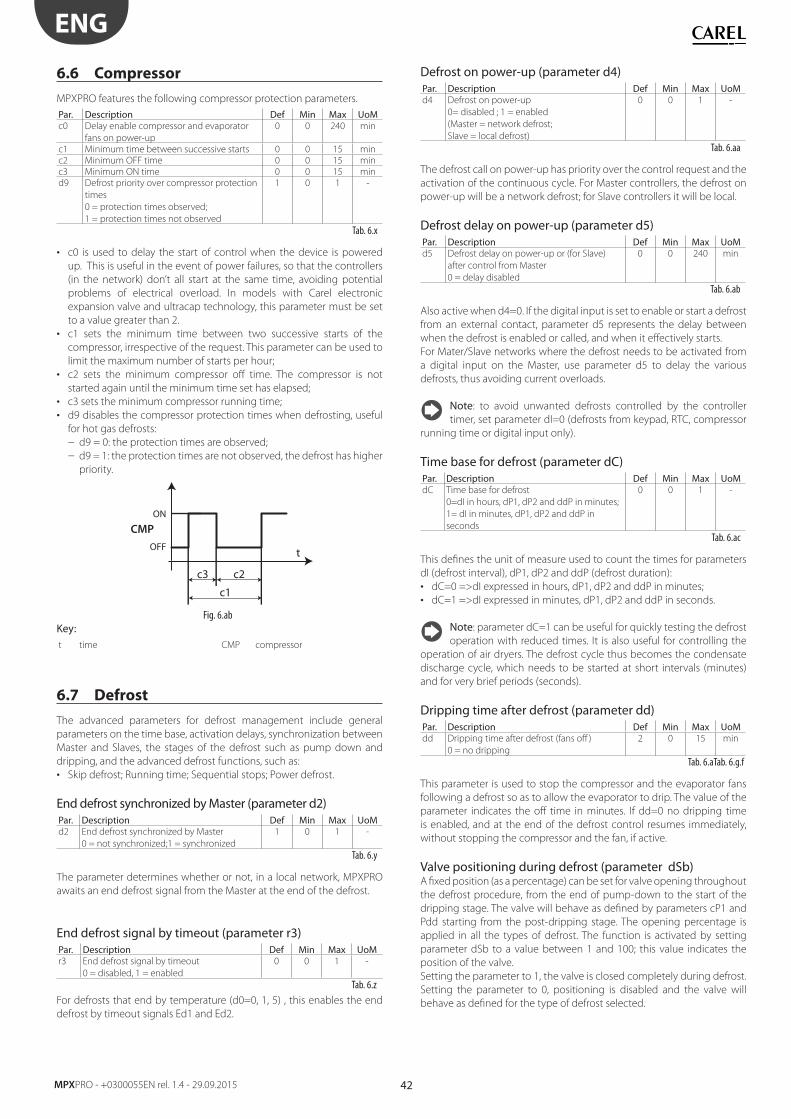
42
ENG
MPXPRO - +0300055EN rel. 1.4 - 29.09.2015
6.6 Compressor
MPXPRO features the following compressor protection parameters.
Par. Description Def Min Max UoMc0 Delay enable compressor and evaporator
fans on power-up
0 0 240 min
c1 Minimum time between successive starts 0 0 15 min
c2 Minimum OFF time 0 0 15 min
c3 Minimum ON time 0 0 15 min
d9 Defrost priority over compressor protection
times
0 = protection times observed;
1 = protection times not observed
1 0 1 -
Tab. 6.x
• c0 is used to delay the start of control when the device is powered
up. This is useful in the event of power failures, so that the controllers
(in the network) don’t all start at the same time, avoiding potential
problems of electrical overload. In models with Carel electronic
expansion valve and ultracap technology, this parameter must be set
to a value greater than 2.
• c1 sets the minimum time between two successive starts of the
compressor, irrespective of the request. This parameter can be used to
limit the maximum number of starts per hour;
• c2 sets the minimum compressor off time. The compressor is not
started again until the minimum time set has elapsed;
• c3 sets the minimum compressor running time;
• d9 disables the compressor protection times when defrosting, useful
for hot gas defrosts:
– d9 = 0: the protection times are observed;
– d9 = 1: the protection times are not observed, the defrost has higher
priority.
c3 c2
c1
t
ON
CMP
OFF
Fig. 6.ab
Key: t time CMP compressor
6.7 Defrost
The advanced parameters for defrost management include general
parameters on the time base, activation delays, synchronization between
Master and Slaves, the stages of the defrost such as pump down and
dripping, and the advanced defrost functions, such as:
• Skip defrost; Running time; Sequential stops; Power defrost.
End defrost synchronized by Master (parameter d2)Par. Description Def Min Max UoMd2 End defrost synchronized by Master
0 = not synchronized;1 = synchronized
1 0 1 -
Tab. 6.y
The parameter determines whether or not, in a local network, MPXPRO
awaits an end defrost signal from the Master at the end of the defrost.
End defrost signal by timeout (parameter r3)Par. Description Def Min Max UoMr3 End defrost signal by timeout
0 = disabled, 1 = enabled
0 0 1 -
Tab. 6.z
For defrosts that end by temperature (d0=0, 1, 5) , this enables the end
defrost by timeout signals Ed1 and Ed2.
Defrost on power-up (parameter d4)Par. Description Def Min Max UoMd4 Defrost on power-up
0= disabled ; 1 = enabled
(Master = network defrost;
Slave = local defrost)
0 0 1 -
Tab. 6.aa
The defrost call on power-up has priority over the control request and the
activation of the continuous cycle. For Master controllers, the defrost on
power-up will be a network defrost; for Slave controllers it will be local.
Defrost delay on power-up (parameter d5)Par. Description Def Min Max UoMd5 Defrost delay on power-up or (for Slave)
after control from Master
0 = delay disabled
0 0 240 min
Tab. 6.ab
Also active when d4=0. If the digital input is set to enable or start a defrost
from an external contact, parameter d5 represents the delay between
when the defrost is enabled or called, and when it eff ectively starts.
For Mater/Slave networks where the defrost needs to be activated from
a digital input on the Master, use parameter d5 to delay the various
defrosts, thus avoiding current overloads.
Note: to avoid unwanted defrosts controlled by the controller
timer, set parameter dI=0 (defrosts from keypad, RTC, compressor
running time or digital input only).
Time base for defrost (parameter dC)Par. Description Def Min Max UoMdC Time base for defrost
0=dI in hours, dP1, dP2 and ddP in minutes;
1= dI in minutes, dP1, dP2 and ddP in
seconds
0 0 1 -
Tab. 6.ac
This defi nes the unit of measure used to count the times for parameters
dI (defrost interval), dP1, dP2 and ddP (defrost duration):
• dC=0 =>dI expressed in hours, dP1, dP2 and ddP in minutes;
• dC=1 =>dI expressed in minutes, dP1, dP2 and ddP in seconds.
Note: parameter dC=1 can be useful for quickly testing the defrost
operation with reduced times. It is also useful for controlling the
operation of air dryers. The defrost cycle thus becomes the condensate
discharge cycle, which needs to be started at short intervals (minutes)
and for very brief periods (seconds).
Dripping time after defrost (parameter dd)Par. Description Def Min Max UoMdd Dripping time after defrost (fans off )
0 = no dripping
2 0 15 min
Tab. 6.aTab. 6.g.f
This parameter is used to stop the compressor and the evaporator fans
following a defrost so as to allow the evaporator to drip. The value of the
parameter indicates the off time in minutes. If dd=0 no dripping time
is enabled, and at the end of the defrost control resumes immediately,
without stopping the compressor and the fan, if active.
Valve positioning during defrost (parameter dSb)A fi xed position (as a percentage) can be set for valve opening throughout
the defrost procedure, from the end of pump-down to the start of the
dripping stage. The valve will behave as defi ned by parameters cP1 and
Pdd starting from the post-dripping stage. The opening percentage is
applied in all the types of defrost. The function is activated by setting
parameter dSb to a value between 1 and 100; this value indicates the
position of the valve.
Setting the parameter to 1, the valve is closed completely during defrost.
Setting the parameter to 0, positioning is disabled and the valve will
behave as defi ned for the type of defrost selected.
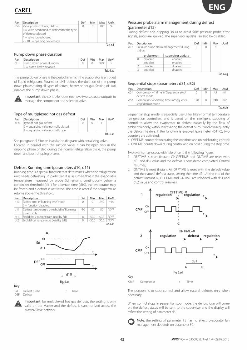
43
ENG
MPXPRO - + 0300055EN rel. 1.4 - 29.09.2015
Par. Description Def Min Max UoMdSb Valve position during defrost.
0 = valve positioned as defi ned for the type
of defrost selected
1 = valve forced closed
2 - 100 = opening percentage
0 0 100 %
Tab. 6.b
Pump down phase durationPar. Description Def Min Max UoMdH1 Pump down phase duration
0 = pump down disabled
0 0 999 s
Tab. 6.ad
The pump down phase is the period in which the evaporator is emptied
of liquid refrigerant. Parameter dH1 defi nes the duration of the pump
down phase during all types of defrost, heater or hot gas. Setting dH1=0
disables the pump down phase.
Important: the controller does not have two separate outputs to
manage the compressor and solenoid valve.
Type of multiplexed hot gas defrostPar. Description Def Min Max UoMdHG Type of hot gas defrost
0 = equalizing valve normally closed
1 = equalizing valve normally open
0 0 1 -
Tab. 6.ae
See paragraph 5.6 for an installation diagram with equalizing valve.
Located in parallel with the suction valve, it can be open only in the
dripping phase or also during the normal refrigeration cycle, the pump
down and post-dripping phases.
Defrost Running time (parameters d10, d11)Running time is a special function that determines when the refrigeration
unit needs defrosting. In particular, it is assumed that if the evaporator
temperature measured by probe Sd remains continuously below a
certain set threshold (d11) for a certain time (d10), the evaporator may
be frozen and a defrost is activated. The time is reset if the temperature
returns above the threshold.
Par. Description Def Min Max UoMd10 Defrost time in “Running time” mode
0 = function disabled
0 0 240 min
d11 Defrost temperature threshold in “Running
time” mode
-30 -50 50 °C/°F
dt1 End defrost temperature (read by Sd) 8 -50.0 50.0 °C/°F
dt2 End defrost temperature (read by Sd2) 8 -50.0 50.0 °C/°F
Tab. 6.af
d10
t
t
ON
Sd
DEFOFF
d1
d11
Fig. 6.ac
KeySd Defrost probe t Time
DEF Defrost
Important: for multiplexed hot gas defrosts, the setting is only
valid on the Master and the defrost is synchronized across the
Master/Slave network.
Pressure probe alarm management during defrost (parameter d12)During defrost and dripping, so as to avoid false pressure probe error
signals, errors are ignored. The supervisor update can also be disabled.
Par. Description Def Min Max UoMd12 Pressure probe alarm management during
defrost
probe error supervisor update0 disabled enabled
1 enabled enabled
2 disabled disabled
3 enabled disabled
0 0 3 -
Tab. 6.ag
Sequential stops (parameters dS1, dS2)Par. Description Def Min Max UoMdS1 Compressor off time in “Sequential stop”
defrost mode
0 0 45 min
dS2 Compressor operating time in “Sequential
stop” defrost mode
120 0 240 min
Tab. 6.ah
Sequential stop mode is especially useful for high-normal temperature
refrigeration controllers, and is based on the intelligent stopping of
control to allow the evaporator to defrost naturally by the fl ow of
ambient air only, without activating the defrost output and consequently
the defrost heaters. If the function is enabled (parameter dS1>0), two
counters are activated:
• OFFTIME: counts down during the stop time and on hold during control;
• ONTIME: counts down during control and on hold during the stop time.
Two events may occur, with reference to the following fi gure:
1. OFFTIME is reset (instant C): OFFTIME and ONTIME are reset with
dS1 and dS2 value and the defrost is considered completed. Control
resumes;
2. ONTIME is reset (instant A): OFFTIME is reset with the default value
and the natural defrost starts, lasting the time dS1. At the end of the
defrost (instant B), OFFTIME and ONTIME are reloaded with dS1 and
dS2 value and control resumes;
C
OFFTIME=0
t
t
ON
1
CMP
regulation regulation
OFF
ONTIME=0
dS1
A B
t
regulationregulation defrost
ON
2
CMPOFF
Fig. 6.ad
KeyCMP Compressor t Time
The purpose is to stop control and allow natural defrosts only when
necessary.
When control stops in sequential stop mode, the defrost icon will come
on, the defrost status will be sent to the supervisor and the display will
refl ect the setting of parameter d6.
Note: the setting of parameter F3 has no eff ect. Evaporator fan
management depends on parameter F0.
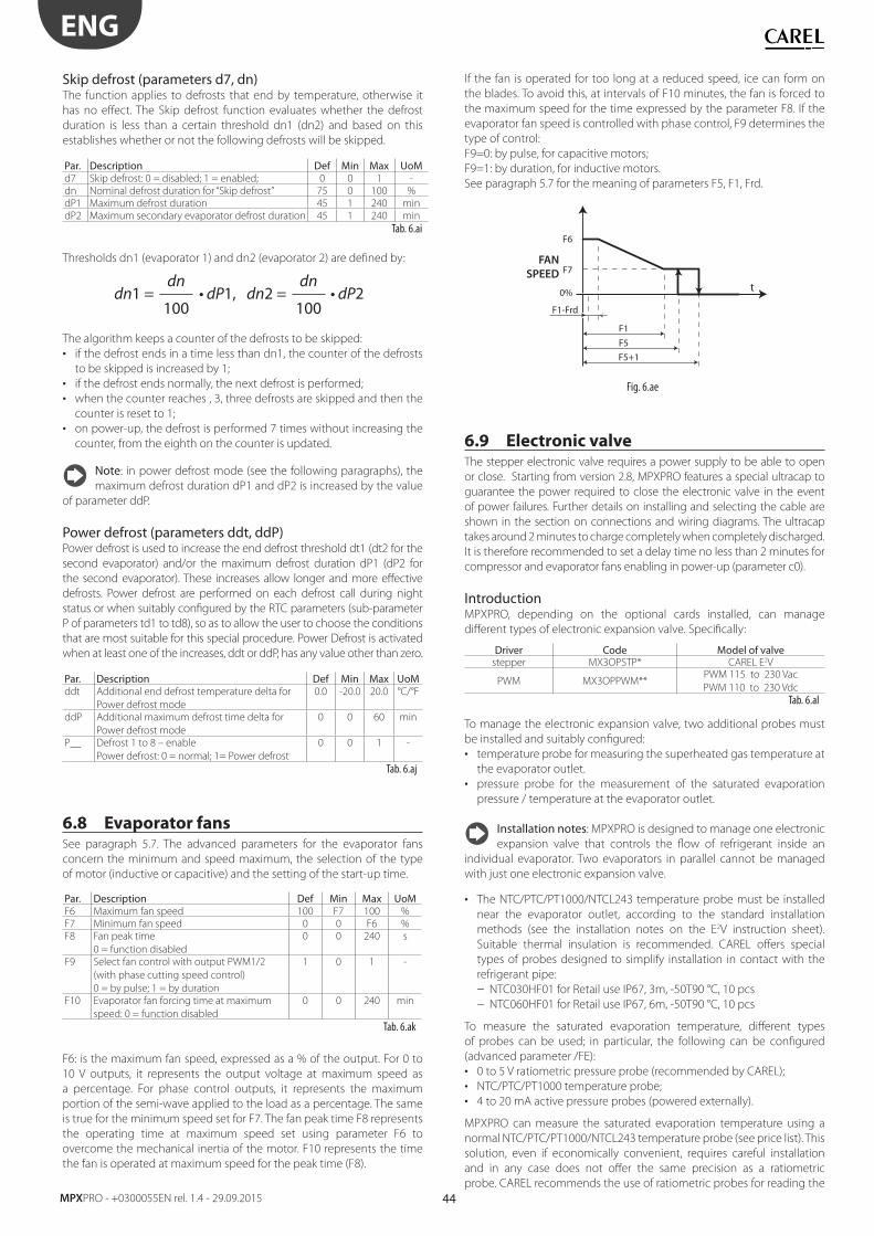
44
ENG
MPXPRO - +0300055EN rel. 1.4 - 29.09.2015
Skip defrost (parameters d7, dn)The function applies to defrosts that end by temperature, otherwise it
has no eff ect. The Skip defrost function evaluates whether the defrost
duration is less than a certain threshold dn1 (dn2) and based on this
establishes whether or not the following defrosts will be skipped.
Par. Description Def Min Max UoMd7 Skip defrost: 0 = disabled; 1 = enabled; 0 0 1 -
dn Nominal defrost duration for “Skip defrost” 75 0 100 %
dP1 Maximum defrost duration 45 1 240 min
dP2 Maximum secondary evaporator defrost duration 45 1 240 min
Tab. 6.ai
Thresholds dn1 (evaporator 1) and dn2 (evaporator 2) are defi ned by:
dn1 = 1, dn2 = 2dn
100
dn
100
The algorithm keeps a counter of the defrosts to be skipped:
• if the defrost ends in a time less than dn1, the counter of the defrosts
to be skipped is increased by 1;
• if the defrost ends normally, the next defrost is performed;
• when the counter reaches , 3, three defrosts are skipped and then the
counter is reset to 1;
• on power-up, the defrost is performed 7 times without increasing the
counter, from the eighth on the counter is updated.
Note: in power defrost mode (see the following paragraphs), the
maximum defrost duration dP1 and dP2 is increased by the value
of parameter ddP.
Power defrost (parameters ddt, ddP)Power defrost is used to increase the end defrost threshold dt1 (dt2 for the
second evaporator) and/or the maximum defrost duration dP1 (dP2 for
the second evaporator). These increases allow longer and more eff ective
defrosts. Power defrost are performed on each defrost call during night
status or when suitably confi gured by the RTC parameters (sub-parameter
P of parameters td1 to td8), so as to allow the user to choose the conditions
that are most suitable for this special procedure. Power Defrost is activated
when at least one of the increases, ddt or ddP, has any value other than zero.
Par. Description Def Min Max UoMddt Additional end defrost temperature delta for
Power defrost mode
0.0 -20.0 20.0 °C/°F
ddP Additional maximum defrost time delta for
Power defrost mode
0 0 60 min
P__ Defrost 1 to 8 – enable
Power defrost: 0 = normal; 1= Power defrost
0 0 1 -
Tab. 6.aj
6.8 Evaporator fansSee paragraph 5.7. The advanced parameters for the evaporator fans
concern the minimum and speed maximum, the selection of the type
of motor (inductive or capacitive) and the setting of the start-up time.
Par. Description Def Min Max UoMF6 Maximum fan speed 100 F7 100 %
F7 Minimum fan speed 0 0 F6 %
F8 Fan peak time
0 = function disabled
0 0 240 s
F9 Select fan control with output PWM1/2
(with phase cutting speed control)
0 = by pulse; 1 = by duration
1 0 1 -
F10 Evaporator fan forcing time at maximum
speed: 0 = function disabled
0 0 240 min
Tab. 6.ak
F6: is the maximum fan speed, expressed as a % of the output. For 0 to
10 V outputs, it represents the output voltage at maximum speed as
a percentage. For phase control outputs, it represents the maximum
portion of the semi-wave applied to the load as a percentage. The same
is true for the minimum speed set for F7. The fan peak time F8 represents
the operating time at maximum speed set using parameter F6 to
overcome the mechanical inertia of the motor. F10 represents the time
the fan is operated at maximum speed for the peak time (F8).
If the fan is operated for too long at a reduced speed, ice can form on
the blades. To avoid this, at intervals of F10 minutes, the fan is forced to
the maximum speed for the time expressed by the parameter F8. If the
evaporator fan speed is controlled with phase control, F9 determines the
type of control:
F9=0: by pulse, for capacitive motors;
F9=1: by duration, for inductive motors.
See paragraph 5.7 for the meaning of parameters F5, F1, Frd.
F5+1
F5
F1
t
FAN
SPEED
0%
F7
F6
F1-Frd
Fig. 6.ae
6.9 Electronic valve The stepper electronic valve requires a power supply to be able to open
or close. Starting from version 2.8, MPXPRO features a special ultracap to
guarantee the power required to close the electronic valve in the event
of power failures. Further details on installing and selecting the cable are
shown in the section on connections and wiring diagrams. The ultracap
takes around 2 minutes to charge completely when completely discharged.
It is therefore recommended to set a delay time no less than 2 minutes for
compressor and evaporator fans enabling in power-up (parameter c0).
IntroductionMPXPRO, depending on the optional cards installed, can manage
diff erent types of electronic expansion valve. Specifi cally:
Driver Code Model of valvestepper MX3OPSTP* CAREL E2V
PWM MX3OPPWM**PWM 115 to 230 Vac
PWM 110 to 230 Vdc
Tab. 6.al
To manage the electronic expansion valve, two additional probes must
be installed and suitably confi gured:
• temperature probe for measuring the superheated gas temperature at
the evaporator outlet.
• pressure probe for the measurement of the saturated evaporation
pressure / temperature at the evaporator outlet.
Installation notes: MPXPRO is designed to manage one electronic
expansion valve that controls the fl ow of refrigerant inside an
individual evaporator. Two evaporators in parallel cannot be managed
with just one electronic expansion valve.
• The NTC/PTC/PT1000/NTCL243 temperature probe must be installed
near the evaporator outlet, according to the standard installation
methods (see the installation notes on the E2V instruction sheet).
Suitable thermal insulation is recommended. CAREL off ers special
types of probes designed to simplify installation in contact with the
refrigerant pipe:
– NTC030HF01 for Retail use IP67, 3m, -50T90 °C, 10 pcs
– NTC060HF01 for Retail use IP67, 6m, -50T90 °C, 10 pcs
To measure the saturated evaporation temperature, diff erent types
of probes can be used; in particular, the following can be confi gured
(advanced parameter /FE):
• 0 to 5 V ratiometric pressure probe (recommended by CAREL);
• NTC/PTC/PT1000 temperature probe;
• 4 to 20 mA active pressure probes (powered externally).
MPXPRO can measure the saturated evaporation temperature using a
normal NTC/PTC/PT1000/NTCL243 temperature probe (see price list). This
solution, even if economically convenient, requires careful installation
and in any case does not off er the same precision as a ratiometric
probe. CAREL recommends the use of ratiometric probes for reading the
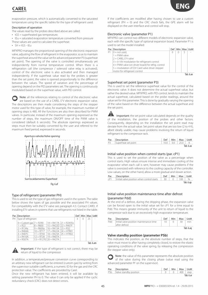
45
ENG
MPXPRO - + 0300055EN rel. 1.4 - 29.09.2015
evaporation pressure, which is automatically converted to the saturated
temperature using the specifi c tables for the type of refrigerant used.
Description of operationThe values read by the probes described above are called:
• tGS = superheated gas temperature;
• tEu = saturated evaporation temperature converted from pressure
These values are used to calculate the superheat:
• SH = tGS - tEu
MPXPRO manages the proportional opening of the electronic expansion
valve, adjusting the fl ow of refrigerant in the evaporator, so as to maintain
the superheat around the value set for advanced parameter P3 (superheat
set point). The opening of the valve is controlled simultaneously yet
independently from normal temperature control. When there is a
refrigeration call (the compressor / solenoid valve relay is activated),
control of the electronic valve is also activated and then managed
independently. If the superheat value read by the probes is greater
than the set point, the valve is opened proportionally to the diff erence
between the values. The speed of variation and the percentage of
opening depend on the PID parameters set. The opening is continuously
modulated based on the superheat value, with PID control.
Note: all the references relating to control of the electronic valve
are based on the use of a CAREL E2V electronic expansion valve.
The descriptions are then made considering the steps of the stepper
motor used for this type of valve, for example, the maximum number of
opening steps is 480. All the functions are also then described for PWM
valves. In particular, instead of the maximum opening expressed as the
number of steps, the maximum ON/OFF time of the PWM valve is
considered (default 6 seconds). The absolute openings expressed as
steps must then be suitably converted by the user and referred to the
maximum fi xed period, expressed in seconds.
Apertura valvola/Valve opening
Surriscaldamento/Superheat
Fig. 6.af
Type of refrigerant (parameter PH)This is used to set the type of gas refrigerant used in the system. The table
below shows the types of gas possible and the associated PH values.
For compatibility with the E2V valve see paragraph 4.3. Contact CAREL if
installing E2V valves in systems that use refrigerants not listed in the table.
Par. Description Def Min Max UoMPH Type of refrigerant
0 = Custom gas 7 = R290 14 = R417A 21 = R245Fa1 = R22 8 = R600 15 = R422D 22 = R407F2 = R134a 9 = R600a 16 = R413A 23 = R323 = R404A 10 = R717 17 = R422A 24 = HTR014 = R407C 11 = R744 18 = R423A 25 = HTR025 = R410A 12 = R728 19 = R407A6 = R507A 13 = R1270 20 = R427A
3 0 25 -
Tab. 6.am
Important: if the type of refrigerant is not correct, there may be
return of liquid to the compressor.
In addition, a temperature/pressure conversion curve corresponding to
an arbitrary new refrigerant can be entered (custom gas) by writing from
the supervisor suitable coeffi cients, a numeric ID for the gas and the CRC
protection value. The coeffi cients are provided by Carel.
Once the new refrigerant has been entered, it will be available by
setting parameter PH to 0. The value 0 can only be applied if the cyclic
redundancy check (CRC) does not detect errors.
If the coeffi cients are modifi ed after having chosen to use a custom
refrigerant (PH = 0) and the CRC check fails, the GPE alarm will be
displayed on the user interface and control will stop.
Electronic valve (parameter P1)MPXPRO can control two diff erent models of electronic expansion valve,
each with the specifi c type of optional expansion board. Parameter P1 is
used to set the model installed:
Par. Description Def Min Max UoMP1 0 = not used,
1 = PWM valve
2 = CAREL E2V valve
3 = 0-10V modulation for refrigerant control
4 = PWM valve (on driver board) for refrig. control
5 = modulation of E2V Carel valve driver stepper
motor for refrigerant control
0 0 5 -
Tab. 6.an
Superheat set point (parameter P3)This is used to set the reference superheat value for the control of the
electronic valve. It does not determine the actual superheat value, but
rather the desired value. MPXPRO, with PID control, tends to maintain the
actual superheat, calculated based on the probe readings, around the
value set for this parameter. This is done by gradually varying the opening
of the valve based on the diff erence between the actual superheat and
the set point.
Important: the set point value calculated depends on the quality
of the installation, the position of the probes and other factors.
Consequently, depending on the installation the set point read may
deviate from the actual value. Set point values that are too low (2 to 4 K),
albeit ideally usable, may cause problems involving the return of liquid
refrigerant to the compressor rack.
Par. Description Def Min Max UoMP3 Superheat set point 10.0 0.0 25.0 K
Tab. 6.ao
Initial valve position when control starts (par. cP1)This is used to set the position of the valve as a percentage when
control starts. High values ensure intense and immediate cooling of the
evaporator when each call is sent, however may cause problems if the
valve is oversized with reference to the cooling capacity of the controller.
Low values, on the other hand, allow a more gradual and slower action.
Par. Description Def Min Max UoMcP1 Initial valve position when control starts 30 0 100 %
Tab. 6.ap
Initial valve position maintenance time after defrost (parameter Pdd)At the end of a defrost, during the dripping phase, the expansion valve
can be forced open to the initial value set for cP1 for a time equal to
Pdd. This means greater immunity of the unit to return of liquid to the
compressor rack due to an excessively high evaporator temperature.
Par. Description Def Min Max UoMPdd Initial valve position maintenance time
after defrost
10 0 30 min
Tab. 6.aq
Valve standby position (parameter PSb)This indicates the position, as the absolute number of steps, that the
valve must move to after having completely closed, to restore the elastic
operating conditions of the valve spring, by releasing the compression
(for stepper valve only).
Note: the value of this parameter represents the absolute position
of the valve during the closing phase (value read using the
advanced parameter PF on the supervisor).
Par. Description Def Min Max UoMPSb Valve standby position 0 0 400 step
Tab. 6.ar
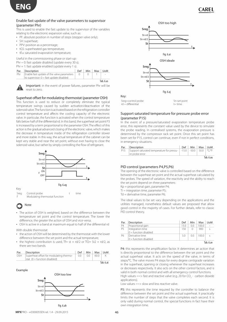
46
ENG
MPXPRO - +0300055EN rel. 1.4 - 29.09.2015
Enable fast update of the valve parameters to supervisor (parameter Phr)This is used to enable the fast update to the supervisor of the variables
relating to the electronic expansion valve, such as:
• PF: absolute position in number of steps (stepper valve only);
• SH: superheat;
• PPV: position as a percentage;
• tGS: superheated gas temperature;
• tEu: saturated evaporation temperature;
Useful in the commissioning phase or start-up:
Phr = 0: fast update disabled (update every 30 s);
Phr = 1: fast update enabled (update every 1 s).
Par. Description Def Min Max UoMPhr Enable fast update of the valve parameters
to supervisor: 0 = fast update disabled
0 0 1 -
Tab. 6.as
Important: in the event of power failures, parameter Phr will be
reset to zero.
Superheat off set for modulating thermostat (parameter OSH)This function is used to reduce or completely eliminate the typical
temperature swings caused by sudden activation/deactivation of the
solenoid valve. The function is activated based on the refrigeration controller
control temperature and aff ects the cooling capacity of the electronic
valve. In particular, the function is activated when the control temperature
falls below half of the diff erential rd. In this band, the superheat set point P3
is increased by a term proportional to the parameter OSH. The eff ect of this
action is the gradual advanced closing of the electronic valve, which makes
the decrease in temperature inside of the refrigeration controller slower
and more stable. In this way, the actual temperature of the cabinet can be
kept very stable and near the set point, without ever having to close the
solenoid valve, but rather by simply controlling the fl ow of refrigerant.
t
t
St+rd
Sreg
St+rd/2
ON
OFFF
St
Fig. 6.ag
Key
Sreg Control probe t time
F Modulating thermostat function
Note:
• The action of OSH is weighted, based on the diff erence between the
temperature set point and the control temperature. The lower the
diff erence, the greater the action of OSH and vice-versa.
• OSH is active in a band at maximum equal to half of the diff erential rd
With double thermostat:
• the action of OSH will be determined by the thermostat with the lower
diff erence between the set point and the actual temperature;
• the highest contribution is used, Tf= st + rd/2 or Tf2= St2 + rd/2, as
there are two bands.
Par. Description Def Min Max UoMOSH Superheat off set for modulating thermo-
stat (0 = function disabled)
0.0 0.0 60.0 K
Tab. 6.at
Example OSH too low
t
St+rd
Sreg
St+rd/2
St
Fig. 6.ah
OSH too high
t
St+rd
Sreg
St+rd/2
St
Fig. 6.ai
OSH ideale
t
St+rd
Sreg
St+rd/2
St
Fig. 6.aj
Key:Sreg=control probe St=set point
rd = diff erential t= time
Support saturated temperature for pressure probe error (parameter P15)In the event of a pressure/saturated evaporation temperature probe
error, this represents the constant value used by the device to simulate
the probe reading. In centralised systems, the evaporation pressure is
determined by the compressor rack set point. Once this set point has
been set for P15, control can continue, even if not in perfect conditions,
in emergency situations.
Par. Description Def Min Max UoMP15 Support saturated temperature for pressu-
re probe error
-15.0 -50.0 50.0 °C/°F
Tab. 6.au
PID control (parameters P4,P5,P6)The opening of the electronic valve is controlled based on the diff erence
between the superheat set point and the actual superheat calculated by
the probes. The speed of variation, the reactivity and the ability to reach
the set point depend on three parameters:
Kp = proportional gain, parameter P4;
Ti = integration time, parameter P5;
Td = derivative time, parameter P6;
The ideal values to be set vary depending on the applications and the
utilities managed, nonetheless default values are proposed that allow
good control in the majority of cases. For further details, refer to classic
PID control theory.
Par. Description Def Min Max UoMP4 Proportional gain 15.0 0.0 100.0 -
P5 Integration time
0 = function disabled
150 0 900 s
P6 Derivative time
0 = function disabled
5.0 0.0 100.0 s
Tab. 6.av
P4: this represents the amplifi cation factor. It determines an action that
is directly proportional to the diff erence between the set point and the
actual superheat value. It acts on the speed of the valve, in terms of
steps/°C. The valve moves P4 steps for every degree centigrade variation
in the superheat, opening or closing whenever the superheat increases
or decreases respectively. It also acts on the other control factors, and is
valid in both normal control and with all emergency control functions.
High values ==> fast and reactive valve (e.g. 20 for CO2 - carbon dioxide
applications).
Low values ==> slow and less reactive valve.
P5: this represents the time required by the controller to balance the
diff erence between the set point and the actual superheat. It practically
limits the number of steps that the valve completes each second. It is
only valid during normal control, the special functions in fact have their
own integration time.
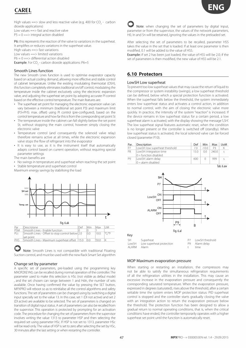
47
ENG
MPXPRO - + 0300055EN rel. 1.4 - 29.09.2015
High values ==> slow and less reactive valve (e.g. 400 for CO2 - carbon
dioxide applications)
Low values ==> fast and reactive valve
P5 = 0 ==> integral action disabled
P6: this represents the reaction of the valve to variations in the superheat.
It amplifi es or reduces variations in the superheat value.
High values ==> fast variations
Low values ==> limited variations
P6 = 0 ==> diff erential action disabled
Example. For CO2 - carbon dioxide applications: P6=5
Smooth Lines functionThe new Smooth Lines function is used to optimise evaporator capacity
based on actual cooling demand, allowing more eff ective and stable control
of cabinet temperature. Unlike the existing modulating thermostat (OSH),
this function completely eliminates traditional on/off control, modulating the
temperature inside the cabinet exclusively using the electronic expansion
valve, and adjusting the superheat set point by adopting accurate PI control
based on the eff ective control temperature. The main features are:
• The superheat set point for managing the electronic expansion valve can
vary between a minimum (traditional set point P3) and maximum limit
(P3+PHS: max. off set) using PI control (pre-confi gured), based on the
control temperature and how far this is from the corresponding set point St
• The temperature inside the cabinet can fall slightly below the set point
St, without stopping the main control, however simply closing the
electronic valve
• Temperature control (and consequently the solenoid valve relay)
therefore remains active at all times, while the electronic expansion
valve stops the fl ow of refrigerant into the evaporator
• It is easy to use, as it is the instrument itself that automatically
adapts control based on current operation, without requiring special
parameter settings
The main benefi ts are
• No swings in temperature and superheat when reaching the set point
• Stable temperature and superheat control
Maximum energy savings by stabilising the load
t
Temp. set
SH set
MAX
MIN
Fig. 6.ak
Par Descrizione Def Min Max UMPSM Smooth Lines - Enable function 0 0 1PLt Smooth Lines - Off set to stop control below
set point
2.0 0.0 10.0 °C/°F
PHS Smooth Lines - Maximum superheat off set 15.0 0.0 50.0 K
Note: Smooth Lines is not compatible with traditional Floating
Suction control, and must be used with the new Rack Smart Set algorithm
Change set by parameterA specifi c set of parameters, pre-loaded using the programming key
MXOPZKEYA0, can be recalled during normal operation of the controller. The
parameter used to make this selection is HSc (not visible as defaul mode)
, and the set chosen can range between 1 and Hdn, the number of sets
available. Once having confi rmed the value by pressing the SET button,
MPXPRO will reboot so as to reinitialise all the control algorithms and safety
functions. The set of parameters can be changed using by switching a digital
input specially set to the value 13. In this case, set 1 (DI not active) and set 2
(DI active) are available to be selected. The set of parameters is changed on
transition of digital input status. A set of parameters can also be recalled from
the supervisor. This operation is protected by prompting for an activation
code. The procedure for changing the set of parameters from the supervisor
involves writing the value 1313 to parameter HSP and then selecting the
required set using parameter HSc. If HSP is not set to 1313, parameter HSc
will be read-only. The value of HSP is set to zero after selecting the set by HSc,
30 minutes after the last setting or when restarting the controller.
Note: when changing the set of parameters by digital input,
parameter or from the supervisor, the values of the network parameters,
H0, In and Sn will be retained, ignoring the values in the preloaded set.
After selecting the set of parameters to be recalled, parameter HSS
takes the value in the set that is loaded. If at least one parameter is then
modifi ed, 0.1 will be added to the value of HSS.
Example: if set 2 has been just loaded, the value of HSS will be 2.0; if the
set of parameters is then modifi ed, the new value of HSS will be 2.1.
6.10 Protectors
LowSH Low superheatTo prevent too low superheat values that may cause the return of liquid to
the compressor or system instability (swings), a low superheat threshold
can be defi ned, below which a special protection function is activated.
When the superheat falls below the threshold, the system immediately
enters low superheat status and activates a control action, in addition
to normal control, with the aim of closing the electronic valve more
quickly. In practice, the intensity of the system “reaction” is increased. If
the device remains in low superheat status for a certain period, a low
superheat alarm is activated, with the display showing the message ‘LSH’.
The low superheat signal features automatic reset, when the condition
is no longer present or the controller is switched off (standby). When
low superheat status is activated, the local solenoid valve can be forced
closed (parameter P10).
Par. Description Def Min Max UoMP7 LowSH: low superheat threshold 7.0 -10.0 P3 K
P8 LowSH: integration time
0 = function disabled
15.0 0.0 240.0 s
P9 LowSH: alarm delay
0 = alarm disabled
600 0 999 s
Tab. 6.aw
t
BP9
t
t
ON
P7
LowSH
SH
OFF
ONALARM
OFF
Fig. 6.al
KeySH Superheat P7 LowSH threshold
LowSH Low superheat protection P9 Alarm delay
ALARM Alarm t time
MOP Maximum evaporation pressure
When starting or restarting an installation, the compressors may
not be able to satisfy the simultaneous refrigeration requirements
of all the refrigeration utilities in the installation. This may cause an
excessive increase in the evaporation pressure and consequently the
corresponding saturated temperature. When the evaporation pressure,
expressed in degrees (saturated), rises above the threshold, after a certain
settable time the system enters MOP protection status: PID superheat
control is stopped and the controller starts gradually closing the valve
with an integration action to return the evaporation pressure below
the threshold. The protection function has been designed to allow a
gradual return to normal operating conditions, that is, when the critical
conditions have ended, the controller temporarily operates with a higher
superheat set point until the function is automatically reset.
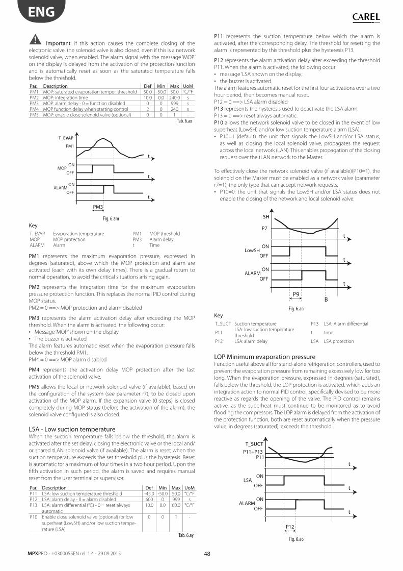
48
ENG
MPXPRO - +0300055EN rel. 1.4 - 29.09.2015
Important: if this action causes the complete closing of the
electronic valve, the solenoid valve is also closed, even if this is a network
solenoid valve, when enabled. The alarm signal with the message ‘MOP’
on the display is delayed from the activation of the protection function
and is automatically reset as soon as the saturated temperature falls
below the threshold.
Par. Description Def Min Max UoMPM1 MOP: saturated evaporation temper. threshold 50.0 -50.0 50.0 °C/°F
PM2 MOP: integration time 10.0 0.0 240.0 s
PM3 MOP: alarm delay - 0 = function disabled 0 0 999 s
PM4 MOP function delay when starting control 2 0 240 s
PM5 MOP: enable close solenoid valve (optional) 0 0 1 -
Tab. 6.ax
t
PM3
t
t
ON
PM1
MOP
T_EVAP
OFF
ONALARM
OFF
Fig. 6.am
KeyT_EVAP Evaporation temperature PM1 MOP threshold
MOP MOP protection PM3 Alarm delay
ALARM Alarm t Time
PM1 represents the maximum evaporation pressure, expressed in
degrees (saturated), above which the MOP protection and alarm are
activated (each with its own delay times). There is a gradual return to
normal operation, to avoid the critical situations arising again.
PM2 represents the integration time for the maximum evaporation
pressure protection function. This replaces the normal PID control during
MOP status.
PM2 = 0 ==> MOP protection and alarm disabled
PM3 represents the alarm activation delay after exceeding the MOP
threshold. When the alarm is activated, the following occur:
• Message ‘MOP’ shown on the display
• The buzzer is activated
The alarm features automatic reset when the evaporation pressure falls
below the threshold PM1.
PM4 = 0 ==> MOP alarm disabled
PM4 represents the activation delay MOP protection after the last
activation of the solenoid valve.
PM5 allows the local or network solenoid valve (if available), based on
the confi guration of the system (see parameter r7), to be closed upon
activation of the MOP alarm. If the expansion valve (0 steps) is closed
completely during MOP status (before the activation of the alarm), the
solenoid valve confi gured is also closed.
LSA - Low suction temperatureWhen the suction temperature falls below the threshold, the alarm is
activated after the set delay, closing the electronic valve or the local and/
or shared tLAN solenoid valve (if available). The alarm is reset when the
suction temperature exceeds the set threshold plus the hysteresis. Reset
is automatic for a maximum of four times in a two hour period. Upon the
fi fth activation in such period, the alarm is saved and requires manual
reset from the user terminal or supervisor.
Par. Description Def Min Max UoMP11 LSA: low suction temperature threshold -45.0 -50.0 50.0 °C/°F
P12 LSA: alarm delay - 0 = alarm disabled 600 0 999 s
P13 LSA: alarm diff erential (°C) - 0 = reset always
automatic
10.0 0.0 60.0 °C/°F
P10 Enable close solenoid valve (optional) for low
superheat (LowSH) and/or low suction tempe-
rature (LSA)
0 0 1 -
Tab. 6.ay
P11 represents the suction temperature below which the alarm is
activated, after the corresponding delay. The threshold for resetting the
alarm is represented by this threshold plus the hysteresis P13.
P12 represents the alarm activation delay after exceeding the threshold
P11. When the alarm is activated, the following occur:
• message ‘LSA’ shown on the display;
• the buzzer is activated
The alarm features automatic reset for the fi rst four activations over a two
hour period, then becomes manual reset.
P12 = 0 ==> LSA alarm disabled
P13 represents the hysteresis used to deactivate the LSA alarm.
P13 = 0 ==> reset always automatic.
P10 allows the network solenoid valve to be closed in the event of low
superheat (LowSH) and/or low suction temperature alarm (LSA).
• P10=1 (default): the unit that signals the LowSH and/or LSA status,
as well as closing the local solenoid valve, propagates the request
across the local network (LAN). This enables propagation of the closing
request over the tLAN network to the Master.
To eff ectively close the network solenoid valve (if available)(P10=1), the
solenoid on the Master must be enabled as a network valve (parameter
r7=1), the only type that can accept network requests.
• P10=0: the unit that signals the LowSH and/or LSA status does not
enable the closing of the network and local solenoid valve.
t
BP9
t
t
ON
P7
LowSH
SH
OFF
ONALARM
OFF
Fig. 6.an
KeyT_SUCT Suction temperature P13 LSA: Alarm diff erential
P11LSA: low suction temperature
threshold t time
P12 LSA: alarm delay LSA LSA protection
LOP Minimum evaporation pressureFunction useful above all for stand-alone refrigeration controllers, used to
prevent the evaporation pressure from remaining excessively low for too
long. When the evaporation pressure, expressed in degrees (saturated),
falls below the threshold, the LOP protection is activated, which adds an
integration action to normal PID control, specifi cally devised to be more
reactive as regards the opening of the valve. The PID control remains
active, as the superheat must continue to be monitored as to avoid
fl ooding the compressors. The LOP alarm is delayed from the activation of
the protection function, both are reset automatically when the pressure
value, in degrees (saturated), exceeds the threshold.
t
t
t
ON
P11+P13P11
LSA
T_SUCT
OFF
ON
P12
ALARMOFF
Fig. 6.ao
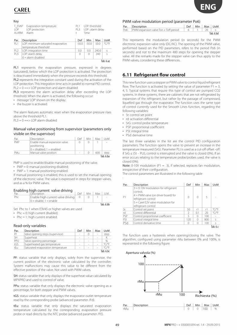
49
ENG
MPXPRO - + 0300055EN rel. 1.4 - 29.09.2015
KeyT_EVAP Evaporation temperature PL1 LOP: threshold
LOP LOP protection PL3 LOP : alarm delay
ALARM Alarm t Time
Par. Description Def Min Max UoMPL1 LOP: minimum saturated evaporation
temperature threshold
-50.0 -50.0 50.0 °C/°F
PL2 LOP: integration time 0.0 0.0 240.0 s
PL3 LOP: alarm delay
0 = alarm disabled
0 0 240 s
Tab. 6.az
PL1 represents the evaporation pressure, expressed in degrees
(saturated), below which the LOP protection is activated. The protection
is deactivated immediately when the pressure exceeds this threshold.
PL2 represents the integration constant used during the activation of the
LOP protection. This integration time acts in parallel to normal PID control.
PL2 = 0 ==> LOP protection and alarm disabled
PL3 represents the alarm activation delay after exceeding the LOP
threshold. When the alarm is activated, the following occur:
• message ‘LOP’ shown on the display;
• the buzzer is activated.
The alarm features automatic reset when the evaporation pressure rises
above the threshold PL1.
PL3 = 0 ==> LOP alarm disabled
Manual valve positioning from supervisor (parameters only visible on the supervisor)Par. Description Def Min Max UoM
PMP Enable manual expansion valve
positioning
0 = disabled; 1 = enabled
0 0 1 -
PMu Manual valve position - 0 600 step
Tab. 6.ba
PMP is used to enable/disable manual positioning of the valve.
• PMP = 0: manual positioning disabled;
• PMP = 1: manual positioning enabled.
If manual positioning is enabled, this is used to set the manual opening
of the electronic valve. The value is expressed in steps for stepper valves,
and as a % for PWM valves.
Enabling high current valve drivingPar. Description Def Min Max U.M.
Phc Enable high current valve driving0 = disable; 1 = enable
0 0 1 -
Tab. 6.bb
Set Phc to 1 when E3V45 or higher valves are used
• Phc = 0: high current disabled;
• Phc = 1: high current enabled.
Read-only variablesPar. Description Def Min Max UoMPF Valve opening steps (supervisor) - 0 - step
SH Superheat - - - K
PPU Valve opening percentage - - - %
tGS Superheated gas temperature - - - °C/°F
tEu Saturated evaporation temperature - - - °C/°F
Tab. 6.bc
PF: status variable that only displays, solely from the supervisor, the
current position of the electronic valve calculated by the controller.
System malfunctions may cause this value to be diff erent from the
eff ective position of the valve. Not used with PWM valves.
SH: status variable that only displays of the superheat value calculated by
MPXPRO and used to control of valve.
PPu: status variable that only displays the electronic valve opening as a
percentage, for both stepper and PWM valves.
tGS: status variable that only displays the evaporator outlet temperature
read by the corresponding probe (advanced parameter /Fd).
tEu: status variable that only displays the saturated evaporation
temperature calculated by the corresponding evaporation pressure
probe or read directly by the NTC probe (advanced parameter /FE).
PWM valve modulation period (parameter Po6)Par. Description Def Min Max UoMPo6 PWM expansion valve Ton + Toff period 6 1 20 s
Tab. 6.bd
This represents the modulation period (in seconds) for the PWM
electronic expansion valve only (DC/AC). The opening of the PWM valve,
performed based on the PID parameters, refers to the period Po6 (in
seconds) and not to the maximum 480 steps for opening the stepper
valve. All the remarks made for the stepper valve can thus apply to the
PWM valves, considering these diff erences.
6.11 Refrigerant fl ow control
This new function uses a stepper or PWM valve to control liquid refrigerant
fl ow. The function is activated by setting the value of parameter P1 = 3,
4, 5. Typical systems that require this type of control are pumped CO2
systems. In these systems, there are cabinets that are not refrigerated by
expansion of the refrigerant, but rather by the passage of compressed,
liquefi ed gas through the evaporator. The function uses the same type
of control currently used for the Smooth Lines function, regarding the
following variables:
• St: control set point
• rd: activation diff erential
• SrG: control probe temperature
• PSP: proportional coeffi cient
• PSI: integral time
• PSd: derivative time
The last three variables in the list are the control PID confi guration
parameters. The function opens the valve to prevent an increase in the
temperature measured (SrG). Parameter PLt is used as a cut-off off set -off :
if SrG ≤ (St – PLt), control is interrupted and the valve is closed (0%). If an
error occurs relating to the temperature probe/probes used, the valve is
closed (0%).
Note: 0-10V modulation (P1 = 3), if selected, replaces fan modulation,
irrespective of their confi guration.
The control parameters are illustrated in the following table
:
Par. Description Def Min Max UoM
P1
3 = 0-10V modulation for refrigerant
control,
4 = PWM valve (on driver board) for
refrigerant control
5 = Carel E2V valve modulation for
refrigerant control
0 0 5 -
St Control set point 50 r1 r1 °C/°F
rd Control diff erential 2 0.1 20 °C/°F
PSP Control proportional coeffi cient 5 0 100 -
PSI Control integral time 120 0 800 s
PSd Control derivative time 0 0 100 s
Tab. 6.c
The function uses a hysteresis when opening/closing the valve. The
algorithm, confi gured using parameter rMu between 0% and 100%, is
represented in the following fi gure:
100
Apertura valvola (%)
rMu
Richiesta (%)100rMu
Par. Description Def Min Max UoMrMu 0 0 100 %
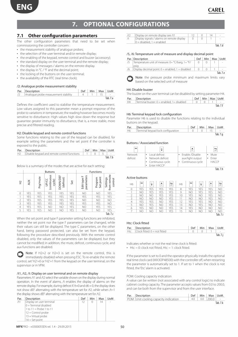
50
ENG
MPXPRO - +0300055EN rel. 1.4 - 29.09.2015
7. OPTIONAL CONFIGURATIONS
7.1 Other confi guration parametersThe other confi guration parameters that need to be set when
commissioning the controller concern :
• the measurement stability of analogue probes;
• the selection of the user terminal and/or remote display;
• the enabling of the keypad, remote control and buzzer (accessory);
• the standard display on the user terminal and the remote display;
• the display of messages / alarms on the remote display.
• the display in °C / °F and the decimal point;
• the locking of the buttons on the user terminal;
• the availability of the RTC (real time clock);
/2: Analogue probe measurement stabilityPar. Description Def Min Max UoM/2 Analogue probe measurement stability 4 1 15 -
Tab. 7.a
Defi nes the coeffi cient used to stabilise the temperature measurement.
Low values assigned to this parameter mean a prompt response of the
probe to variations in temperature; the reading however becomes mostly
sensitive to disturbance. High values high slow down the response but
guarantee greater immunity to disturbance, that is, a more stable, more
precise and fi ltered reading.
H2: Disable keypad and remote control functionsSome functions relating to the use of the keypad can be disabled, for
example setting the parameters and the set point if the controller is
exposed to the public.
Par. Description Def Min Max UoMH2 Disable keypad and remote control functions 1 0 5 -
Tab. 7.b
Below is a summary of the modes that are active for each setting:
Buttons Functions
H2
AU
X
Prg/
mut
e
UP/
CC
(con
tinuo
us
cycl
e)
DO
WN
/DEF
(d
efro
st)
Set
Edit
typ
e F
par
amet
ers
Prog
ram
Se
t poi
nt
Sett
ings
fr
om re
mot
e co
ntro
l
0 YES YES YES YES YES NO NO YES
1 YES YES YES YES YES YES YES YES
2 YES YES YES YES YES NO NO NO
3 YES YES YES YES YES YES YES NO
4 YES YES NO NO YES NO YES YES
5 YES YES NO NO YES NO NO YES
Tab. 7.c
When the set point and type F parameter setting functions are inhibited,
neither the set point nor the type F parameters can be changed, while
their values can still be displayed. The type C parameters, on the other
hand, being password protected, can also be set from the keypad,
following the procedure described previously. With the remote control
disabled, only the values of the parameters can be displayed, but they
cannot be modifi ed; in addition, the mute, defrost, continuous cycle, and
aux functions are disabled.
Note: If H2=2 or H2=3 is set on the remote control, this is
immediately disabled when pressing ESC. To re-enable the remote
control, set ‘H2’=0 or ‘H2’=1 from the keypad on the user terminal, on the
supervisor or in VPM.
/t1, /t2, /t: Display on user terminal and on remote displayParameters /t1 and /t2 select the variable shown on the display during normal
operation. In the event of alarms, /t enables the display of alarms on the
remote display. For example, during defrost if /t=0 and d6 = 0, the display does
not show dEF alternating with the temperature set for /t2, while when /t=1
the display shows dEF alternating with the temperature set for /t2.
Par. Description Def Min Max UoM/t1 Display on user terminal
0 = Terminal disabled
1 to 11 = Probe 1 to 11
12 = Control probe
13 = Virtual probe
14 = Set point
12 0 14 -
/t2 Display on remote display see /t1 12 0 14 -/t Display signals / alarms on remote display
0 = disabled, 1 = enabled
0 0 1 -
Tab. 7.d
/5, /6: Temperature unit of measure and display decimal pointPar. Description Def Min Max UoM/5 Temperature unit of measure: 0= °C/barg, 1= °F/
psig
0 0 1 -
/6 Display decimal point: 0 = enabled, 1 = disabled 0 0 1 -
Tab. 7.e
Note: the pressure probe minimum and maximum limits vary
based on the selected unit of measure
H4: Disable buzzer The buzzer on the user terminal can be disabled by setting parameter H4.
Par. Description Def Min Max UoMH4 Terminal buzzer: 0 = enabled; 1= disabled 0 0 1 -
Tab. 7.f
H6: Terminal keypad lock confi gurationParameter H6 is used to disable the functions relating to the individual
buttons on the keypad.
Par. Description Def Min Max UoMH6 Terminal keypad lock confi guration 0 0 15 -
Tab. 7.g
Buttons / Associated function
Network
defrost
• Local defrost
• Network defrost
• Continuous cycle
• Enter HACCP
• Enable /Disable
aux/light output
• Continuous cycle
• Mute
• Enter
HACCP
Tab. 7.h
Active buttons
H6
H6
0 YES YES YES YES 8 YES YES YES NO1 NO YES YES YES 9 NO YES YES NO2 NO NO YES YES 10 YES NO YES NO3 NO NO NO YES 11 NO NO YES NO4 YES YES NO YES 12 YES YES NO NO5 NO YES NO YES 13 NO YES NO NO6 YES NO NO YES 14 YES NO NO NO7 NO NO NO YES 15 NO NO NO NO
Tab. 7.i
Htc: Clock fi ttedPar. Description Def Min Max UoMHtc Clock fi tted: 0 = not fi tted 0 0 1 -
Tab. 7.j
Indicates whether or not the real time clock is fi tted:
• Htc = 0: clock not fi tted, Htc = 1: clock fi tted.
If the parameter is set to 0 and the operator physically installs the optional
real time clock card (MX3OP48500) with the controller off , when restarting
the parameter is automatically set to 1. If set to 1 when the clock is not
fi tted, the ‘Etc’ alarm is activated.
POM: Cooling capacity indication
A value can be written (not associated with any control logic) to indicate
cabinet cooling capacity. The parameter accepts values from 0.0 to 200.0,
and can be both from the supervisor and from the user interface.
Par. Description Def Min Max UoM.POM Unit cooling capacity indication 4.0 0.0 200.0 -
Tab. 7.k
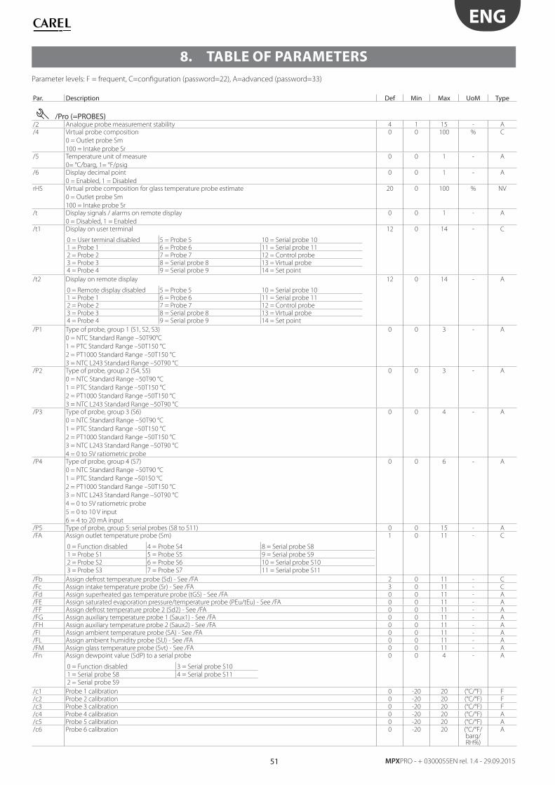
51
ENG
MPXPRO - + 0300055EN rel. 1.4 - 29.09.2015
8. TABLE OF PARAMETERS
Parameter levels: F = frequent, C=confi guration (password=22), A=advanced (password=33)
Par. Description Def Min Max UoM Type
/Pro (=PROBES)/2 Analogue probe measurement stability 4 1 15 - A/4 Virtual probe composition
0 = Outlet probe Sm
100 = Intake probe Sr
0 0 100 % C
/5 Temperature unit of measure
0= °C/barg, 1= °F/psig
0 0 1 - A
/6 Display decimal point
0 = Enabled, 1 = Disabled
0 0 1 - A
rHS Virtual probe composition for glass temperature probe estimate
0 = Outlet probe Sm
100 = Intake probe Sr
20 0 100 % NV
/t Display signals / alarms on remote display
0 = Disabled, 1 = Enabled
0 0 1 - A
/t1 Display on user terminal
0 = User terminal disabled 5 = Probe 5 10 = Serial probe 101 = Probe 1 6 = Probe 6 11 = Serial probe 112 = Probe 2 7 = Probe 7 12 = Control probe3 = Probe 3 8 = Serial probe 8 13 = Virtual probe4 = Probe 4 9 = Serial probe 9 14 = Set point
12 0 14 - C
/t2 Display on remote display
0 = Remote display disabled 5 = Probe 5 10 = Serial probe 101 = Probe 1 6 = Probe 6 11 = Serial probe 112 = Probe 2 7 = Probe 7 12 = Control probe3 = Probe 3 8 = Serial probe 8 13 = Virtual probe4 = Probe 4 9 = Serial probe 9 14 = Set point
12 0 14 - A
/P1 Type of probe, group 1 (S1, S2, S3)
0 = NTC Standard Range –50T90°C
1 = PTC Standard Range –50T150 °C
2 = PT1000 Standard Range –50T150 °C
3 = NTC L243 Standard Range –50T90 °C
0 0 3 - A
/P2 Type of probe, group 2 (S4, S5)
0 = NTC Standard Range –50T90 °C
1 = PTC Standard Range –50T150 °C
2 = PT1000 Standard Range –50T150 °C
3 = NTC L243 Standard Range –50T90 °C
0 0 3 - A
/P3 Type of probe, group 3 (S6)
0 = NTC Standard Range –50T90 °C
1 = PTC Standard Range –50T150 °C
2 = PT1000 Standard Range –50T150 °C
3 = NTC L243 Standard Range –50T90 °C
4 = 0 to 5V ratiometric probe
0 0 4 - A
/P4 Type of probe, group 4 (S7)
0 = NTC Standard Range –50T90 °C
1 = PTC Standard Range –50150 °C
2 = PT1000 Standard Range –50T150 °C
3 = NTC L243 Standard Range –50T90 °C
4 = 0 to 5V ratiometric probe
5 = 0 to 10 V input
6 = 4 to 20 mA input
0 0 6 - A
/P5 Type of probe, group 5: serial probes (S8 to S11) 0 0 15 - A/FA Assign outlet temperature probe (Sm)
0 = Function disabled 4 = Probe S4 8 = Serial probe S8
1 = Probe S1 5 = Probe S5 9 = Serial probe S9
2 = Probe S2 6 = Probe S6 10 = Serial probe S10
3 = Probe S3 7 = Probe S7 11 = Serial probe S11
1 0 11 - C
/Fb Assign defrost temperature probe (Sd) - See /FA 2 0 11 - C/Fc Assign intake temperature probe (Sr) - See /FA 3 0 11 - C/Fd Assign superheated gas temperature probe (tGS) - See /FA 0 0 11 - A/FE Assign saturated evaporation pressure/temperature probe (PEu/tEu) - See /FA 0 0 11 - A/FF Assign defrost temperature probe 2 (Sd2) - See /FA 0 0 11 - A/FG Assign auxiliary temperature probe 1 (Saux1) - See /FA 0 0 11 - A/FH Assign auxiliary temperature probe 2 (Saux2) - See /FA 0 0 11 - A/FI Assign ambient temperature probe (SA) - See /FA 0 0 11 - A/FL Assign ambient humidity probe (SU) - See /FA 0 0 11 - A/FM Assign glass temperature probe (Svt) - See /FA 0 0 11 - A/Fn Assign dewpoint value (SdP) to a serial probe
0 = Function disabled 3 = Serial probe S10
1 = Serial probe S8 4 = Serial probe S11
2 = Serial probe S9
0 0 4 - A
/c1 Probe 1 calibration 0 -20 20 (°C/°F) F/c2 Probe 2 calibration 0 -20 20 (°C/°F) F/c3 Probe 3 calibration 0 -20 20 (°C/°F) F/c4 Probe 4 calibration 0 -20 20 (°C/°F) A/c5 Probe 5 calibration 0 -20 20 (°C/°F) A/c6 Probe 6 calibration 0 -20 20 (°C/°F/
barg/ RH%)
A
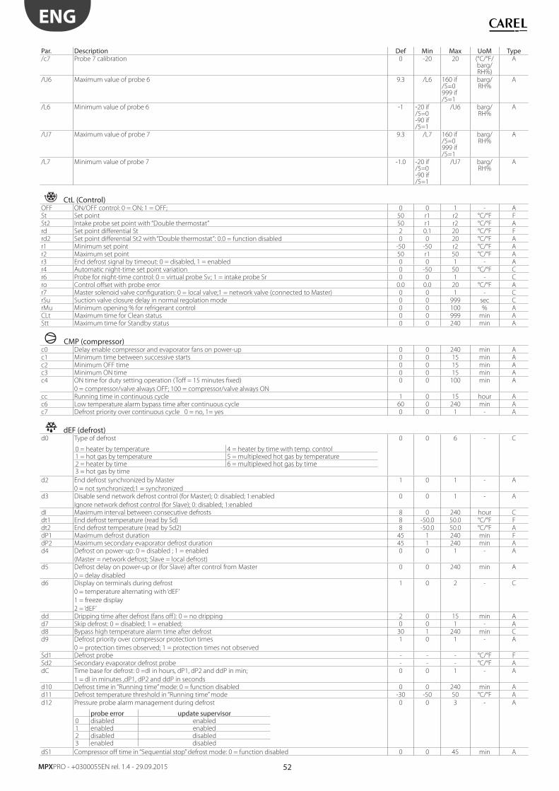
52
ENG
MPXPRO - +0300055EN rel. 1.4 - 29.09.2015
Par. Description Def Min Max UoM Type/c7 Probe 7 calibration 0 -20 20 (°C/°F/
barg/ RH%)
A
/U6 Maximum value of probe 6 9.3 /L6 160 if /5=0999 if /5=1
barg/ RH%
A
/L6 Minimum value of probe 6 -1 -20 if /5=0-90 if /5=1
/U6 barg/ RH%
A
/U7 Maximum value of probe 7 9.3 /L7 160 if /5=0999 if /5=1
barg/ RH%
A
/L7 Minimum value of probe 7 -1.0 -20 if /5=0-90 if /5=1
/U7 barg/ RH%
A
CtL (Control)OFF ON/OFF control: 0 = ON; 1 = OFF; 0 0 1 - ASt Set point 50 r1 r2 °C/°F FSt2 Intake probe set point with “Double thermostat” 50 r1 r2 °C/°F Ard Set point diff erential St 2 0.1 20 °C/°F Frd2 Set point diff erential St2 with “Double thermostat”: 0.0 = function disabled 0 0 20 °C/°F Ar1 Minimum set point -50 -50 r2 °C/°F Ar2 Maximum set point 50 r1 50 °C/°F Ar3 End defrost signal by timeout: 0 = disabled, 1 = enabled 0 0 1 - Ar4 Automatic night-time set point variation 0 -50 50 °C/°F Cr6 Probe for night-time control: 0 = virtual probe Sv; 1 = intake probe Sr 0 0 1 - Cro Control off set with probe error 0.0 0.0 20 °C/°F Ar7 Master solenoid valve confi guration: 0 = local valve;1 = network valve (connected to Master) 0 0 1 - CrSu Suction valve closure delay in normal regolation mode 0 0 999 sec CrMu Minimum opening % for refrigerant control 0 0 100 % ACLt Maximum time for Clean status 0 0 999 min AStt Maximum time for Standby status 0 0 240 min A
CMP (compressor)c0 Delay enable compressor and evaporator fans on power-up 0 0 240 min Ac1 Minimum time between successive starts 0 0 15 min Ac2 Minimum OFF time 0 0 15 min Ac3 Minimum ON time 0 0 15 min Ac4 ON time for duty setting operation (Toff = 15 minutes fi xed)
0 = compressor/valve always OFF; 100 = compressor/valve always ON
0 0 100 min A
cc Running time in continuous cycle 1 0 15 hour Ac6 Low temperature alarm bypass time after continuous cycle 60 0 240 min Ac7 Defrost priority over continuous cycle 0 = no, 1= yes 0 0 1 - A
dEF (defrost)d0 Type of defrost
0 = heater by temperature 4 = heater by time with temp. control1 = hot gas by temperature 5 = multiplexed hot gas by temperature2 = heater by time 6 = multiplexed hot gas by time3 = hot gas by time
0 0 6 - C
d2 End defrost synchronized by Master
0 = not synchronized;1 = synchronized
1 0 1 - A
d3 Disable send network defrost control (for Master); 0: disabled; 1:enabled
Ignore network defrost control (for Slave); 0: disabled; 1:enabled
0 0 1 - A
dI Maximum interval between consecutive defrosts 8 0 240 hour Cdt1 End defrost temperature (read by Sd) 8 -50.0 50.0 °C/°F Fdt2 End defrost temperature (read by Sd2) 8 -50.0 50.0 °C/°F AdP1 Maximum defrost duration 45 1 240 min FdP2 Maximum secondary evaporator defrost duration 45 1 240 min Ad4 Defrost on power-up: 0 = disabled ; 1 = enabled
(Master = network defrost; Slave = local defrost)
0 0 1 - A
d5 Defrost delay on power-up or (for Slave) after control from Master
0 = delay disabled
0 0 240 min A
d6 Display on terminals during defrost
0 = temperature alternating with ‘dEF’
1 = freeze display
2 = ‘dEF’
1 0 2 - C
dd Dripping time after defrost (fans off ): 0 = no dripping 2 0 15 min Ad7 Skip defrost: 0 = disabled; 1 = enabled; 0 0 1 - Ad8 Bypass high temperature alarm time after defrost 30 1 240 min Cd9 Defrost priority over compressor protection times
0 = protection times observed; 1 = protection times not observed
1 0 1 - A
Sd1 Defrost probe - - - °C/°F FSd2 Secondary evaporator defrost probe - - - °C/°F AdC Time base for defrost: 0 =dI in hours, dP1, dP2 and ddP in min;
1 = dI in minutes ,dP1, dP2 and ddP in seconds
0 0 1 - A
d10 Defrost time in “Running time” mode: 0 = function disabled 0 0 240 min Ad11 Defrost temperature threshold in “Running time” mode -30 -50 50 °C/°F A
d12 Pressure probe alarm management during defrost
probe error update supervisor0 disabled enabled1 enabled enabled2 disabled disabled3 enabled disabled
0 0 3 - A
dS1 Compressor off time in “Sequential stop” defrost mode: 0 = function disabled 0 0 45 min A
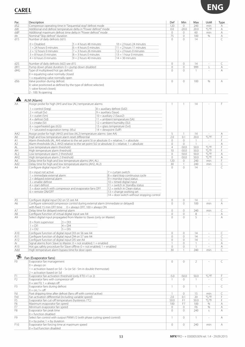
53
ENG
MPXPRO - + 0300055EN rel. 1.4 - 29.09.2015
Par. Description Def Min Max UoM TypedS2 Compressor operating time in “Sequential stop” defrost mode 120 0 240 min Addt Additional end defrost temperature delta in “Power defrost” mode 0.0 -20.0 20.0 °C/°F AddP Additional maximum defrost time delta in “Power defrost” mode 0 0 60 min Adn Nominal “Skip defrost” duration 75 0 100 % Ad1S Number of daily defrosts (td1)
0 = Disabled 5 = 4 hours 48 minutes 10 = 2 hours 24 minutes
1 = 24 hours 0 minutes 6 = 4 hours 0 minutes 11 = 2 hours 11 minutes
2 = 12 hours 0 minutes 7 = 3 hours 26 minutes 12 = 2 hours 0 minutes
3 = 8 hours 0 minutes 8 = 3 hours 0 minutes 13 = 1 hour 0 minutes
4 = 6 hours 0 minutes 9 = 2 hours 40 minutes 14 = 30 minutes
0 0 14 - C
d2S Number of daily defrosts (td2) see d1S 0 0 14 - CdH1 Pump down phase duration: 0 = pump down disabled 0 0 999 s AdHG Type of multiplexed hot gas defrost
0 = equalizing valve normally closed
1 = equalizing valve normally open
0 0 1 - A
dSb Valve position during defrost:
0: valve positioned as defi ned by the type of defrost selected;
1: valve forced closed;
2 - 100: % opening
0 0 100 % A
ALM (Alarm)AA Assign probe for high (AH) and low (AL) temperature alarms
1 = control (Sreg) 8 = auxiliary defrost (Sd2)
2 = virtual (Sv) 9 = auxiliary (Saux)
3 = outlet (Sm) 10 = auxiliary 2 (Saux2)
4 = defrost (Sd) 11 = ambient temperature (SA)
5 = intake (Sr) 12 = ambient humidity (SU)
6 = superheated gas (tGS) 13 = glass temperature (Svt)
7 = saturated evaporation temp. (tEu) 14 = dewpoint (SdP)
1 1 14 - F
AA2 Assign probe for high (AH2) and low (AL2) temperature alarms (see AA) 5 1 14 - AA0 High and low temperature alarm reset diff erential 2.0 0.1 20.0 °C/°F FA1 Alarm thresholds (AL, AH) relative to the set point St or absolute: 0 = relative; 1 = absolute 0 0 1 - FA2 Alarm thresholds (AL2, AH2) relative to the set point St2 or absolute: 0 = relative; 1 = absolute 0 0 1 - AAL Low temperature alarm threshold 4 -50.0 50.0 °C/°F FAH High temperature alarm threshold 10 -50.0 50.0 °C/°F FAL2 Low temperature alarm 2 threshold 0 -50.0 50.0 °C/°F AAH2 High temperature alarm 2 threshold 0 -50.0 50.0 °C/°F AAd Delay time for high and low temperature alarms (AH, AL) 120 0 240 min FAd2 Delay time for high and low temperature alarms (AH2, AL2) 30 1 240 min CA4 Confi gure digital input DI1 on S4
0 = input not active 7 = curtain switch1 = immediate external alarm 8 = start/stop continuous cycle2 = delayed external alarm 9 = monitor input status3 = enable defrost 10 = timed digital input4 = start defrost 11 = switch in Standby status5 = door switch with compressor and evaporator fans OFF 12 = switch in Clean status6 = remote ON/OFF 13 = change working set
14 = door switch without stopping control
0 0 14 - C
A5 Confi gure digital input DI2 on S5 see A4 0 0 14 - CA6 Confi gure solenoid/compressor control during external alarm (immediate or delayed)
with fi xed 15 min OFF time 0 = always OFF; 100 = always ON
0 0 100 min A
A7 Delay time for delayed external alarm 0 0 240 min CA8 Confi gure function of virtual digital input see A4 0 0 8 - AA9 Select digital input propagated from Master to Slaves (only on Master)
0 = from supervisor 3 = DI3
1 = DI1 4 = DI4
2 = DI2 5 = DI5
0 0 5 - A
A10 Confi gure function of digital input DI3 on S6 see A4 0 0 14 - CA11 Confi gure function of digital input DI4 on S7 see A4 0 0 14 - CA12 Confi gure function of digital input DI5 see A4 0 0 14 - CAr Signal alarms from Slave to Master: 0 = not enabled; 1 = enabled 1 0 1 - AA13 Hot gas safety procedure for Slave offl ine: 0 = not enabled; 1 = enabled 0 0 1 - AAdd High temperature alarm bypass time for door open 30 1 240 min C
Fan (Evaporator fans)F0 Evaporator fan management
0 = always on
1 = activation based on Sd – Sv (or Sd - Sm in double thermostat)
2 = activation based on Sd
0 0 2 - C
F1 Evaporator fan activation threshold (only if F0 =1 or 2) -5.0 -50.0 50.0 °C/°F FF2 Evaporator fans with compressor off
0 = see F0; 1 = always off
1 0 1 - C
F3 Evaporator fans during defrost
0 = on; 1= off
1 0 1 - C
Fd Post dripping time after defrost (fans off with control active) 1 0 15 min CFrd Fan activation diff erential (including variable speed) 2.0 0.1 20 °C/°F FF5 Evaporator fan cut-off temperature (hysteresis 1°C) 50.0 F1 50.0 °C/°F FF6 Maximum evaporator fan speed 100 F7 100 % AF7 Minimum evaporator fan speed 0 0 F6 % AF8 Evaporator fan peak time
0 = function disabled
0 0 240 s A
F9 Select fan control with output PWM1/2 (with phase cutting speed control)
0 = by pulse; 1 = by duration
1 0 1 - A
F10 Evaporator fan forcing time at maximum speed
0 = Eud function disabled
0 0 240 min A
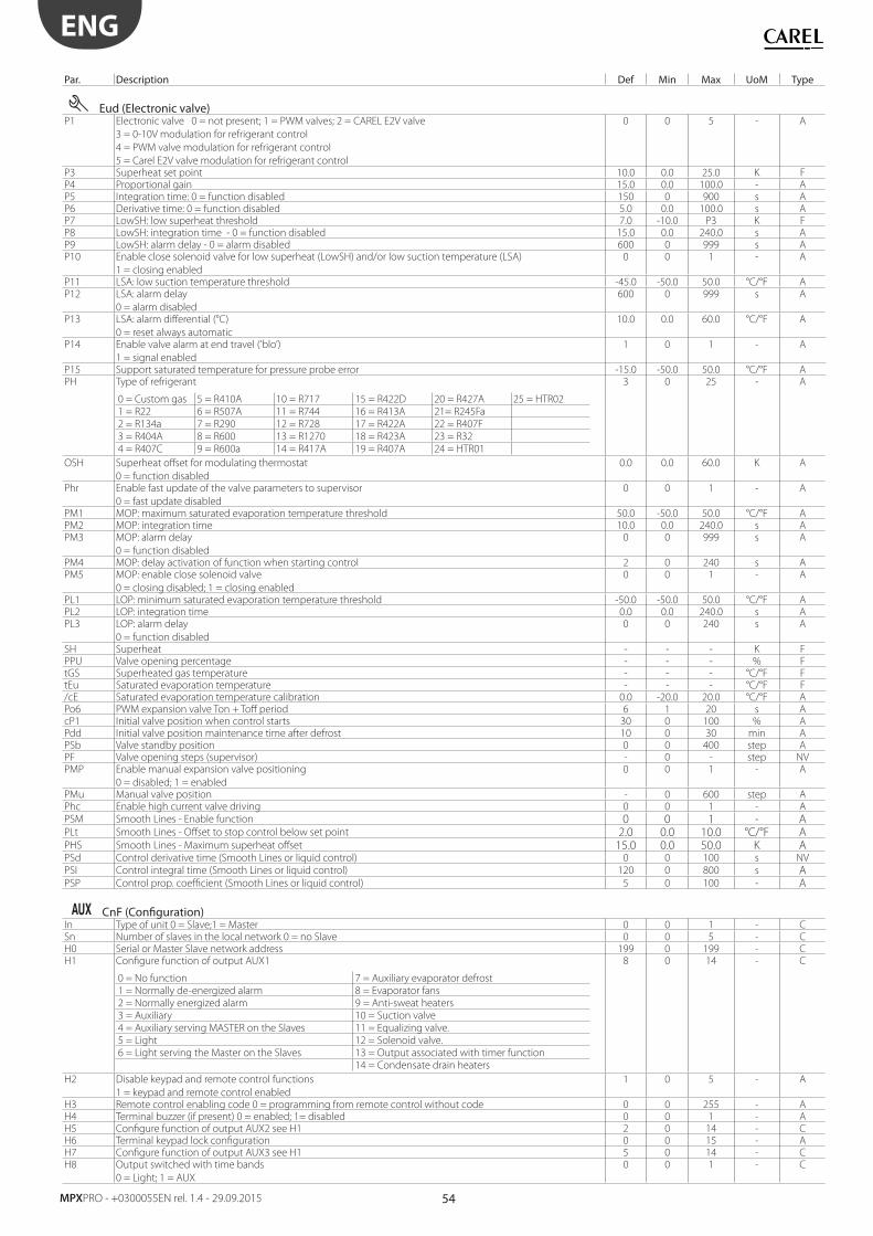
54
ENG
MPXPRO - +0300055EN rel. 1.4 - 29.09.2015
Par. Description Def Min Max UoM Type
Eud (Electronic valve)P1 Electronic valve 0 = not present; 1 = PWM valves; 2 = CAREL E2V valve
3 = 0-10V modulation for refrigerant control
4 = PWM valve modulation for refrigerant control
5 = Carel E2V valve modulation for refrigerant control
0 0 5 - A
P3 Superheat set point 10.0 0.0 25.0 K FP4 Proportional gain 15.0 0.0 100.0 - AP5 Integration time: 0 = function disabled 150 0 900 s AP6 Derivative time: 0 = function disabled 5.0 0.0 100.0 s AP7 LowSH: low superheat threshold 7.0 -10.0 P3 K FP8 LowSH: integration time - 0 = function disabled 15.0 0.0 240.0 s AP9 LowSH: alarm delay - 0 = alarm disabled 600 0 999 s AP10 Enable close solenoid valve for low superheat (LowSH) and/or low suction temperature (LSA)
1 = closing enabled
0 0 1 - A
P11 LSA: low suction temperature threshold -45.0 -50.0 50.0 °C/°F AP12 LSA: alarm delay
0 = alarm disabled
600 0 999 s A
P13 LSA: alarm diff erential (°C)
0 = reset always automatic
10.0 0.0 60.0 °C/°F A
P14 Enable valve alarm at end travel (‘blo’)
1 = signal enabled
1 0 1 - A
P15 Support saturated temperature for pressure probe error -15.0 -50.0 50.0 °C/°F APH Type of refrigerant
0 = Custom gas 5 = R410A 10 = R717 15 = R422D 20 = R427A 25 = HTR02
1 = R22 6 = R507A 11 = R744 16 = R413A 21= R245Fa
2 = R134a 7 = R290 12 = R728 17 = R422A 22 = R407F
3 = R404A 8 = R600 13 = R1270 18 = R423A 23 = R32
4 = R407C 9 = R600a 14 = R417A 19 = R407A 24 = HTR01
3 0 25 - A
OSH Superheat off set for modulating thermostat
0 = function disabled
0.0 0.0 60.0 K A
Phr Enable fast update of the valve parameters to supervisor
0 = fast update disabled
0 0 1 - A
PM1 MOP: maximum saturated evaporation temperature threshold 50.0 -50.0 50.0 °C/°F APM2 MOP: integration time 10.0 0.0 240.0 s APM3 MOP: alarm delay
0 = function disabled
0 0 999 s A
PM4 MOP: delay activation of function when starting control 2 0 240 s APM5 MOP: enable close solenoid valve
0 = closing disabled; 1 = closing enabled
0 0 1 - A
PL1 LOP: minimum saturated evaporation temperature threshold -50.0 -50.0 50.0 °C/°F APL2 LOP: integration time 0.0 0.0 240.0 s APL3 LOP: alarm delay
0 = function disabled
0 0 240 s A
SH Superheat - - - K FPPU Valve opening percentage - - - % FtGS Superheated gas temperature - - - °C/°F FtEu Saturated evaporation temperature - - - °C/°F F/cE Saturated evaporation temperature calibration 0.0 -20.0 20.0 °C/°F APo6 PWM expansion valve Ton + Toff period 6 1 20 s AcP1 Initial valve position when control starts 30 0 100 % APdd Initial valve position maintenance time after defrost 10 0 30 min APSb Valve standby position 0 0 400 step APF Valve opening steps (supervisor) - 0 - step NVPMP Enable manual expansion valve positioning
0 = disabled; 1 = enabled
0 0 1 - A
PMu Manual valve position - 0 600 step APhc Enable high current valve driving 0 0 1 - A
PSM Smooth Lines - Enable function 0 0 1 - APLt Smooth Lines - Off set to stop control below set point 2.0 0.0 10.0 °C/°F APHS Smooth Lines - Maximum superheat off set 15.0 0.0 50.0 K APSd Control derivative time (Smooth Lines or liquid control) 0 0 100 s NV
PSI Control integral time (Smooth Lines or liquid control) 120 0 800 s APSP Control prop. coeffi cient (Smooth Lines or liquid control) 5 0 100 - A
CnF (Confi guration)In Type of unit 0 = Slave;1 = Master 0 0 1 - CSn Number of slaves in the local network 0 = no Slave 0 0 5 - CH0 Serial or Master Slave network address 199 0 199 - CH1 Confi gure function of output AUX1
0 = No function 7 = Auxiliary evaporator defrost
1 = Normally de-energized alarm 8 = Evaporator fans
2 = Normally energized alarm 9 = Anti-sweat heaters
3 = Auxiliary 10 = Suction valve
4 = Auxiliary serving MASTER on the Slaves 11 = Equalizing valve.
5 = Light 12 = Solenoid valve.
6 = Light serving the Master on the Slaves 13 = Output associated with timer function
14 = Condensate drain heaters
8 0 14 - C
H2 Disable keypad and remote control functions
1 = keypad and remote control enabled
1 0 5 - A
H3 Remote control enabling code 0 = programming from remote control without code 0 0 255 - AH4 Terminal buzzer (if present) 0 = enabled; 1= disabled 0 0 1 - AH5 Confi gure function of output AUX2 see H1 2 0 14 - CH6 Terminal keypad lock confi guration 0 0 15 - AH7 Confi gure function of output AUX3 see H1 5 0 14 - CH8 Output switched with time bands
0 = Light; 1 = AUX
0 0 1 - C
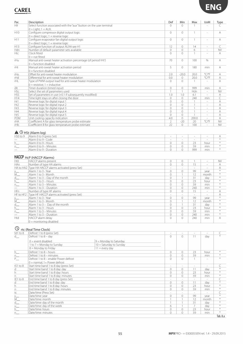
55
ENG
MPXPRO - + 0300055EN rel. 1.4 - 29.09.2015
Par. Description Def Min Max UoM TypeH9 Select function associated with the “aux” button on the user terminal
0 = Light; 1 = AUX.
0 0 1 - C
H10 Confi gure compressor digital output logic
0 = direct logic; 1 = reverse logic
0 0 1 - A
H11 Confi gure evaporator fan digital output logic
0 = direct logic; 1 = reverse logic
0 0 1 - A
H13 Confi gure function of output AUX4 see H1 12 0 14 - CHdn Number of default parameter sets available 0 0 6 - NVHtc Clock fi tted
0 = not fi tted
0 0 1 - A
rHu Manual anti-sweat heater activation percentage (of period ‘rHt’)
0 = function disabled
70 0 100 % A
rHt Manual anti-sweat heater activation period
0 = function disabled
5 0 180 min A
rHo Off set for anti-sweat heater modulation 2.0 -20.0 20.0 °C/°F ArHd Diff erential for anti-sweat heater modulation 0.0 0 20.0 °C/°F ArHL Type of PWM output load for anti-sweat heater modulation
0 = resistive; 1 = inductive
0 0 1 - A
dIt Timer duration (timed input) 0 0 999 min AHSc Select the set of parameters used 1 1 Hdn - NVHSS Set of parameters in use (+0.1 if subsequently modifi ed) 1.0 1.0 6.1 - AH14 Time light stays on after closing the door 0 0 240 min CHr1 Reverse logic for digital input 1 0 0 1 - AHr2 Reverse logic for digital input 2 0 0 1 - AHr3 Reverse logic for digital input 3 0 0 1 - AHr4 Reverse logic for digital input 4 0 0 1 - AHr5 Reverse logic for digital input 5 0 0 1 - APOM Unit cooling capacity indication 4.0 0 200.0 - ArHA Coeffi cient A for glass temperature probe estimate 2 -20 20 °C/°F NVrHb Coeffi cient B for glass temperature probe estimate 22 0 100 - NV
HSt (Alarm log)HS0 to 9 Alarm 0 to 9 (press Set) - - - - A--- Alarm 0 to 9 - Code - - - - *h__ Alarm 0 to 9 - Hours 0 0 23 hour *n__ Alarm 0 to 9 – Minutes 0 0 59 min *--- Alarm 0 to 9 - Duration 0 0 999 min *
HcP (HACCP Alarms)Ht0 HACCP alarms present 0 0 1 - NVHAn Number of type HA alarms 0 0 15 - AHA to HA2 Type HA HACCP alarms activated (press Set) - - - - Ay__ Alarm 1 to 3 - Year 0 0 99 year *M__ Alarm 1 to 3 - Month 0 1 12 month *d__ Alarm 1 to 3 – Day of the month 0 1 31 day *h__ Alarm 1 to 3 – Hours 0 0 23 hour *n__ Alarm 1 to 3 – Minutes 0 0 59 min *--- Alarm 1 to 3 – Duration 0 0 240 min *HFn Number of type HF alarms 0 0 15 - AHF to HF2 Type HF HACCP alarms activated (press Set) - - - - Ay__ Alarm 1 to 3 - Year 0 0 99 year *M__ Alarm 1 to 3 - Month 0 1 12 month *d__ Alarm 1 to 3 – Day of the month 0 1 31 day *h__ Alarm 1 to 3 – Hours 0 0 23 hour *n__ Alarm 1 to 3 – Minutes 0 0 59 min *--- Alarm 1 to 3 – Duration 0 0 240 min *Htd HACCP alarm delay
0 = monitoring disabled
0 0 240 min A
rtc (Real Time Clock)td1 to 8 Defrost 1 to 8 (press Set) - - - - Cd__ Defrost 1 to 8 – day
0 = event disabled 9 = Monday to Saturday
1 to 7 = Monday to Sunday 10 = Saturday to Sunday
8 = Monday to Friday 11 = every day
0 0 11 day *
h__ Defrost 1 to 8 – hours 0 0 23 hour *n__ Defrost 1 to 8 – minutes 0 0 59 min *P__ Defrost 1 to 8 – enable Power defrost
0 = normal; 1= Power defrost
0 0 1 - *
tS1 to 8 Start time band 1 to 8 day (press Set) - - - - Cd Start time band 1 to 8 day: day 0 0 11 day *h Start time band 1 to 8 day: hours 0 0 23 hour *n Start time band 1 to 8 day: minutes 0 0 59 min *tE1 to 8 End time band 1 to 8 day (press Set) - - - - Cd End time band 1 to 8 day: day 0 0 11 day *h End time band 1 to 8 day: hours 0 0 23 hour *n End time band 1 to 8 day: minutes 0 0 59 min *tc Date/time (Press Set) - - - - Cy__ Date/time: year 0 0 99 year *M__ Date/time: month 1 1 12 month *d__ Date/time: day of the month 1 1 31 day *u__ Date/time: day of the week 6 1 7 day *h__ Date/time: hours 0 0 23 hour *n__ Date/time: minutes 0 0 59 min *
Tab. 8.a
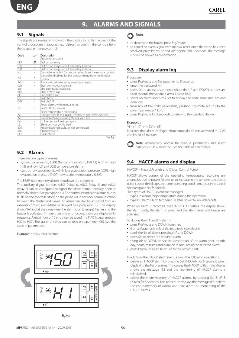
56
ENG
MPXPRO - +0300055EN rel. 1.4 - 29.09.2015
9. ALARMS AND SIGNALS
9.1 SignalsThe signals are messages shown on the display to notify the user of the
control procedures in progress (e.g. defrost) or confi rm the controls from
the keypad or remote control.
Code Icon Description--- - Probe not enabled
dEF Defrost running
Ed1 - Defrost on evaporator 1 ended by timeoutEd2 - Defrost on evaporator 2 ended by timeoutrct - Controller enabled for programming from the remote control
rcE -Controller disabled for the programming from the remote
controlAdd - Automatic address assignment in progressccb - Start continuous cycle callccE - End continuous cycle calldFb - Start defrost calldFE - End defrost callOn - Switch ONOFF - Switch OFF
rES -
Reset alarms with manual reset
Reset HACCP alarms
Reset temperature monitoringAcE - Change from PI to ON/OFF control of anti-sweat heatersAct - Control of Slaves serving Master via tLANCn - Upload procedure in progressuS_ - Slave unit not confi gured205 - Probe displayed faulty or not connectedStb - Standby statusCLn - Clean status
Tab. 9.a
9.2 AlarmsThere are two types of alarms:
• system: valve motor, EEPROM, communication, HACCP, high (HI and
HI2) and low (LO and LO2) temperature alarms;
• control: low superheat (LowSH), low evaporation pressure (LOP), high
evaporation pressure (MOP), low suction temperature (LSA).
The EE/EF data memory alarms shutdown the controller.
The auxiliary digital outputs AUX1 (relay 4), AUX2 (relay 5) and AUX3
(relay 2) can be confi gured to signal the alarm status, normally open or
normally closed. See paragraph 5.4. The controller indicates alarms due to
faults on the controller itself, on the probes or in network communication
between the Master and Slaves. An alarm can also be activated from an
external contact, immediate or delayed. See paragraph 5.2. The display
shows “IA” and at the same time the alarm icon (triangle) fl ashes and the
buzzer is activated. If more than one error occurs, these are displayed in
sequence. A maximum of 10 errors can be saved, in a FIFO list (parameters
HS0 to HS9). The last error saved can be read on parameter HS0 (see the
table of parameters).
Example: display after HI error:
MP
XPR
OM
PX
PRO
Fig. 9.a
Note:
• to deactivate the buzzer press Prg/mute;
• to cancel an alarm signal with manual reset, once the cause has been
resolved, press Prg/mute and UP together for 5 seconds. The message
rES will be shown as confi rmation.
9.3 Display alarm log
Procedure:
• press Prg/mute and Set together for 5 seconds;
• enter the password: 44;
• press Set to access a submenu where the UP and DOWN buttons are
used to scroll the various alarms, HS0 to HS9;
• select an alarm and press Set to display the code, hour, minutes and
duration;
• from any of the child parameters, pressing Prg/mute returns to the
parent parameter “HSx”;
• press Prg/mute for 5 seconds to return to the standard display.
Example :‘HI’ -> ‘h17’ -> ‘m23’ -> ‘65’
indicates that alarm ‘HI’ (high temperature alarm) was activated at 17:23
and lasted 65 minutes.
Note: alternatively, access the type A parameters and select
category “HSt” = alarm log. See the table of parameters.
9.4 HACCP alarms and display
(HACCP = Hazard Analysis and Critical Control Point).
HACCP allows control of the operating temperature, recording any
anomalies due to power failures or an increase in the temperature due to
other causes (breakages, extreme operating conditions, user errors, etc.);
see paragraph 9.6 for details.
Two types of HACCP event are managed:
• type HA alarms, high temperature during the operation;
• type HF alarms, high temperature after power failure (blackout).
When an alarm is recorded, the HACCP LED fl ashes, the display shows
the alarm code, the alarm is saved and the alarm relay and buzzer are
activated.
To display the HA and HF alarms:
• press Prg/mute and DOWN together;
• if on a Master unit, select the required network unit;
• scroll the list of alarms pressing UP and DOWN;
• press Set to select the required alarm;
• using UP or DOWN to see the description of the alarm: year, month,
day, hours, minutes and duration in minutes of the selected alarm;
• press Prg/mute again to return to the previous list.
In addition, the HACCP alarm menu allows the following operations:
• delete an HACCP alarm by pressing Set & DOWN for 5 seconds when
displaying the list of alarms. This causes the HACCP to fl ash, the display
shows the message rES and the monitoring of HACCP alarms is
reinitialised;
• delete the entire memory of HACCP alarms, by pressing Set & UP &
DOWN for 5 seconds. This procedure displays the message rES, deletes
the entire memory of alarms and reinitialises the monitoring of the
HACCP alarms.
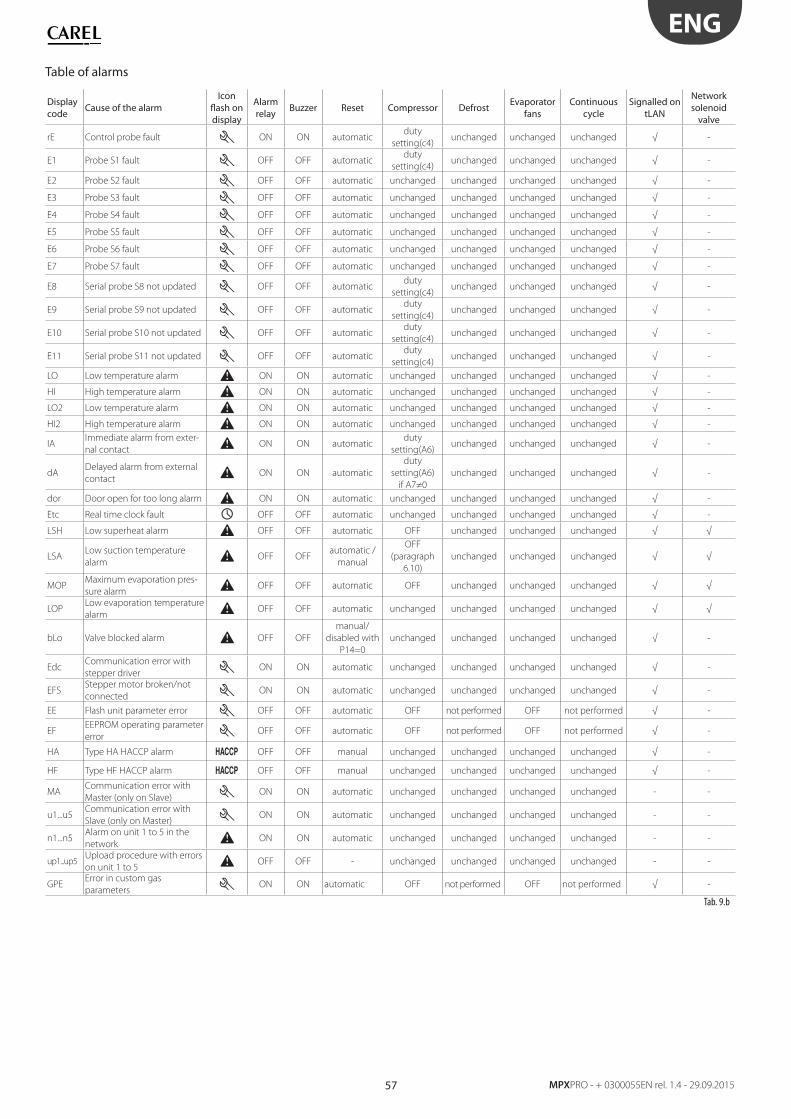
57
ENG
MPXPRO - + 0300055EN rel. 1.4 - 29.09.2015
Table of alarms
Display code
Cause of the alarmIcon
fl ash on display
Alarm relay
Buzzer Reset Compressor DefrostEvaporator
fansContinuous
cycleSignalled on
tLAN
Network solenoid
valve
rE Control probe fault ON ON automaticduty
setting(c4)unchanged unchanged unchanged √ -
E1 Probe S1 fault OFF OFF automaticduty
setting(c4)unchanged unchanged unchanged √ -
E2 Probe S2 fault OFF OFF automatic unchanged unchanged unchanged unchanged √ -
E3 Probe S3 fault OFF OFF automatic unchanged unchanged unchanged unchanged √ -
E4 Probe S4 fault OFF OFF automatic unchanged unchanged unchanged unchanged √ -
E5 Probe S5 fault OFF OFF automatic unchanged unchanged unchanged unchanged √ -
E6 Probe S6 fault OFF OFF automatic unchanged unchanged unchanged unchanged √ -
E7 Probe S7 fault OFF OFF automatic unchanged unchanged unchanged unchanged √ -
E8 Serial probe S8 not updated OFF OFF automaticduty
setting(c4)unchanged unchanged unchanged √ -
E9 Serial probe S9 not updated OFF OFF automaticduty
setting(c4)unchanged unchanged unchanged √ -
E10 Serial probe S10 not updated OFF OFF automaticduty
setting(c4)unchanged unchanged unchanged √ -
E11 Serial probe S11 not updated OFF OFF automaticduty
setting(c4)unchanged unchanged unchanged √ -
LO Low temperature alarm ON ON automatic unchanged unchanged unchanged unchanged √ -
HI High temperature alarm ON ON automatic unchanged unchanged unchanged unchanged √ -
LO2 Low temperature alarm ON ON automatic unchanged unchanged unchanged unchanged √ -
HI2 High temperature alarm ON ON automatic unchanged unchanged unchanged unchanged √ -
IAImmediate alarm from exter-
nal contactON ON automatic
duty
setting(A6)unchanged unchanged unchanged √ -
dADelayed alarm from external
contactON ON automatic
duty
setting(A6)
if A7≠0
unchanged unchanged unchanged √ -
dor Door open for too long alarm ON ON automatic unchanged unchanged unchanged unchanged √ -
Etc Real time clock fault OFF OFF automatic unchanged unchanged unchanged unchanged √ -
LSH Low superheat alarm OFF OFF automatic OFF unchanged unchanged unchanged √ √
LSALow suction temperature
alarmOFF OFF
automatic /
manual
OFF
(paragraph
6.10)
unchanged unchanged unchanged √ √
MOPMaximum evaporation pres-
sure alarmOFF OFF automatic OFF unchanged unchanged unchanged √ √
LOPLow evaporation temperature
alarmOFF OFF automatic unchanged unchanged unchanged unchanged √ √
bLo Valve blocked alarm OFF OFF
manual/
disabled with
P14=0
unchanged unchanged unchanged unchanged √ -
EdcCommunication error with
stepper driverON ON automatic unchanged unchanged unchanged unchanged √ -
EFSStepper motor broken/not
connectedON ON automatic unchanged unchanged unchanged unchanged √ -
EE Flash unit parameter error OFF OFF automatic OFF not performed OFF not performed √ -
EFEEPROM operating parameter
errorOFF OFF automatic OFF not performed OFF not performed √ -
HA Type HA HACCP alarm OFF OFF manual unchanged unchanged unchanged unchanged √ -
HF Type HF HACCP alarm OFF OFF manual unchanged unchanged unchanged unchanged √ -
MACommunication error with
Master (only on Slave)ON ON automatic unchanged unchanged unchanged unchanged - -
u1...u5Communication error with
Slave (only on Master)ON ON automatic unchanged unchanged unchanged unchanged - -
n1...n5Alarm on unit 1 to 5 in the
networkON ON automatic unchanged unchanged unchanged unchanged - -
up1...up5Upload procedure with errors
on unit 1 to 5OFF OFF - unchanged unchanged unchanged unchanged - -
GPEError in custom gas
parametersON ON automatic OFF not performed OFF not performed √ -
Tab. 9.b
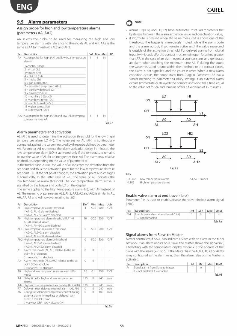
58
ENG
MPXPRO - +0300055EN rel. 1.4 - 29.09.2015
9.5 Alarm parameters
Assign probe for high and low temperature alarms (parameters AA, AA2)
AA selects the probe to be used for measuring the high and low
temperature alarms with reference to thresholds AL and AH. AA2 is the
same as AA for thresholds AL2 and AH2.
Par Description Def Min Max UMAA Assign probe for high (AH) and low (AL) temperature
alarms
1=control (Sreg)
2=virtual (Sv)
3=outlet (Sm)
4 = defrost (Sd)
5 = intake (Sr)
6 = gas surrisc. (tGS)
7 = saturated evap. temp. (tEu)
8 = auxiliary defrost (Sd2)
9 = auxiliary (Saux)
10 = auxiliary 2 (Saux2)
11 = ambient temp. (SA)
12 = amb. humidity (SU)
13 = glass temp. (Svt)
14 = dewpoint (SdP)
1 1 14 -
AA2 Assign probe for high (AH2) and low (AL2) tempera-
ture alarms - see AA
5 1 14 -
Tab. 9.c
Alarm parameters and activationAL (AH) is used to determine the activation threshold for the low (high)
temperature alarm LO (HI). The value set for AL (AH) is continuously
compared against the value measured by the probe defi ned by parameter
AA. Parameter Ad represents the alarm activation delay, in minutes; the
low temperature alarm (LO) is activated only if the temperature remains
below the value of AL for a time greater than Ad. The alarm may relative
or absolute, depending on the value of parameter A1.
In the former case (A1=0), the value of AL indicates the deviation from the
set point and thus the activation point for the low temperature alarm is:
set point - AL. If the set point changes, the activation point also changes
automatically. In the latter case (A1=1), the value of AL indicates the
low temperature alarm threshold. The low temperature alarm active is
signalled by the buzzer and code LO on the display.
The same applies to the high temperature alarm (HI), with AH instead of
AL. The meaning of parameters AL2, AH2, AA2, A2 and Ad2 is similar to AL,
AH, AA, A1 and Ad however relating to St2.
Par Description Def Min Max UoMAL Low temperature alarm threshold
If A1=0, AL=0: alarm disabled
If A1=1, AL=-50: alarm disabled
4 -50.0 50.0 °C/°F
AH High temperature alarm threshold If A1=0,
AH=0: alarm disabled
If A1=1, AH=50: alarm disabled
10 -50.0 50.0 °C/°F
AL2 Low temperature alarm 2 threshold
If A2=0, AL2=0: alarm disabled
If A2=1, AL2=-50: alarm disabled
0 -50.0 50.0 °C/°F
AH2 High temperature alarm 2 threshold
If A2=0, AH2=0: alarm disabled
If A2=1, AH2=50: alarm disabled
0 -50.0 50.0 °C/°F
A1 Alarm thresholds (AL, AH) relative to the set
point St or absolute
0 = relative; 1 = absolute
0 0 1 -
A2 Alarm thresholds (AL2, AH2) relative to the set
point St2 or absolute
0 = relative; 1 = absolute
0 0 1 -
A0 High and low temperature alarm reset diff e-
rential
2.0 0.1 20.0 °C/°F
Ad Delay time for high and low temperature
alarms
120 0 240 min
Ad2 High and low temperature alarm delay (AL2, AH2) 120 0 240 min
A7 Delay time for delayed external alarm (AL, AH) 0 0 240 min
A6 Confi gure solenoid/compressor control during
external alarm (immediate or delayed) with
fi xed 15 min OFF time
0 = always OFF; 100 = always ON
0 0 100 min
Tab. 9.d
Note:
• alarms LO(LO2) and HI(HI2) have automatic reset. A0 represents the
hysteresis between the alarm activation value and deactivation value;
• if Prg/mute is pressed when the value measured is above one of the
thresholds, the buzzer is immediately muted, while the alarm code
and the alarm output, if set, remain active until the value measured
is outside of the activation threshold. For delayed alarms from digital
input (A4=3, code dA), the contact must remain open for a time greater
than A7. In the case of an alarm event, a counter starts and generates
an alarm when reaching the minimum time A7. If during the count
the value measured returns within the threshold or the contact closes,
the alarm is not signalled and the count is reset. When a new alarm
condition occurs, the count starts from 0 again. Parameter A6 has a
similar meaning to parameter c4 (duty setting). If an external alarm
occurs (immediate or delayed) the compressor works for a time equal
to the value set for A6 and remains off for a fi xed time of 15 minutes.
A0A0AL AH
HILO
S1
ON
OFF
A0A0AL2 AH2
HI2LO2
S2
ON
OFF
Fig. 9.b
KeyLO, LO2 Low temperature alarms S1, S2 Probes
HI, HI2 High temperature alarms
Enable valve alarm at end travel (‘blo’)Parameter P14 is used to enable/disable the valve blocked alarm signal
(‘blo’).
Par. Description Def Min Max UoMP14 Enable valve alarm at end travel (‘blo’)
1 = signal enabled
1 0 1 -
Tab. 9.e
Signal alarms from Slave to MasterMaster controllers, if Ar=1, can indicate a Slave with an alarm in the tLAN
network. If an alarm occurs on a Slave, the Master shows the signal “nx”,
alternating with the temperature display, where x is the address of the
Slave with the alarm (x=1 to 5). If the Master has the AUX1, AUX2 or AUX3
relay confi gured as the alarm relay, then the alarm relay on the Master is
activated.
Par. Description Def Min Max UoMAr Signal alarms from Slave to Master
0 = not enabled; 1 = enabled
1 0 1 -
Tab. 9.f
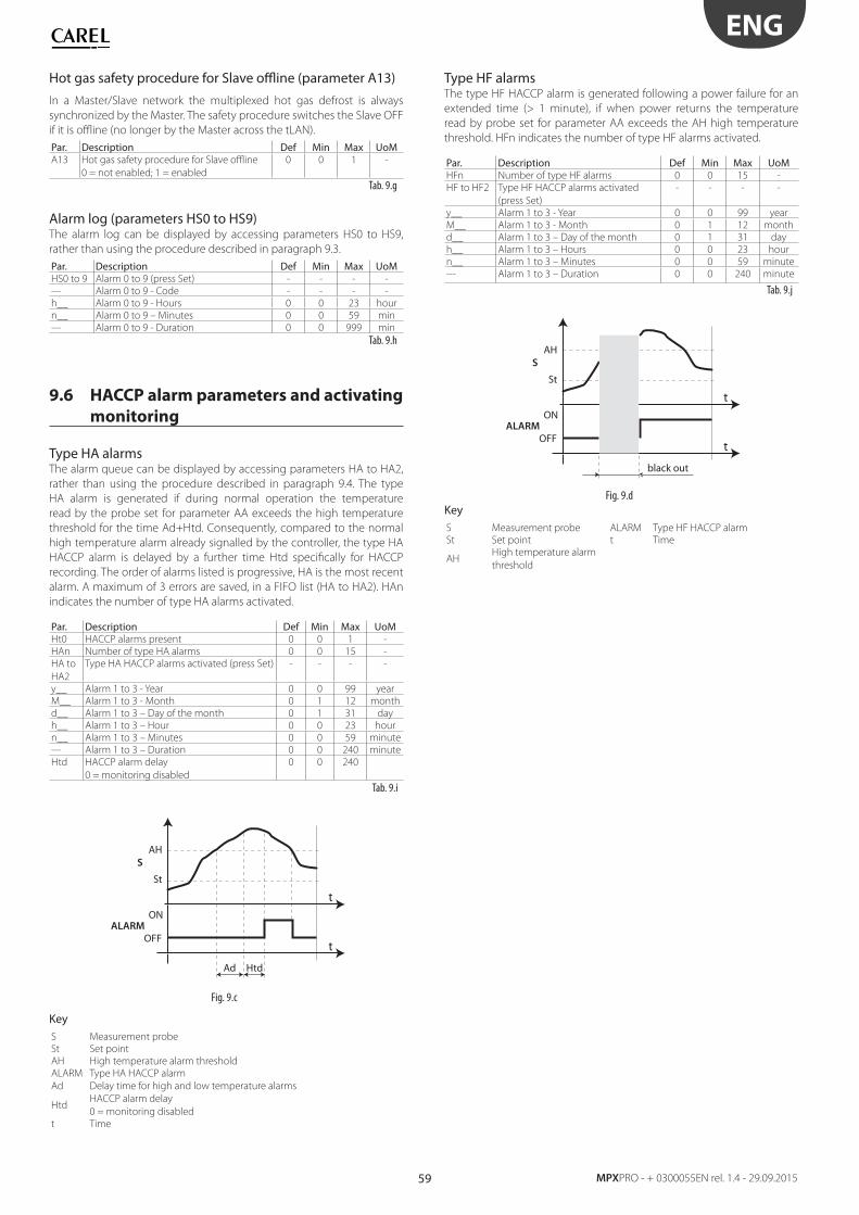
59
ENG
MPXPRO - + 0300055EN rel. 1.4 - 29.09.2015
Hot gas safety procedure for Slave offl ine (parameter A13)
In a Master/Slave network the multiplexed hot gas defrost is always
synchronized by the Master. The safety procedure switches the Slave OFF
if it is offl ine (no longer by the Master across the tLAN).
Par. Description Def Min Max UoMA13 Hot gas safety procedure for Slave offl ine
0 = not enabled; 1 = enabled
0 0 1 -
Tab. 9.g
Alarm log (parameters HS0 to HS9)The alarm log can be displayed by accessing parameters HS0 to HS9,
rather than using the procedure described in paragraph 9.3.
Par. Description Def Min Max UoMHS0 to 9 Alarm 0 to 9 (press Set) - - - -
--- Alarm 0 to 9 - Code - - - -
h__ Alarm 0 to 9 - Hours 0 0 23 hour
n__ Alarm 0 to 9 – Minutes 0 0 59 min
--- Alarm 0 to 9 - Duration 0 0 999 min
Tab. 9.h
9.6 HACCP alarm parameters and activating
monitoring
Type HA alarmsThe alarm queue can be displayed by accessing parameters HA to HA2,
rather than using the procedure described in paragraph 9.4. The type
HA alarm is generated if during normal operation the temperature
read by the probe set for parameter AA exceeds the high temperature
threshold for the time Ad+Htd. Consequently, compared to the normal
high temperature alarm already signalled by the controller, the type HA
HACCP alarm is delayed by a further time Htd specifi cally for HACCP
recording. The order of alarms listed is progressive, HA is the most recent
alarm. A maximum of 3 errors are saved, in a FIFO list (HA to HA2). HAn
indicates the number of type HA alarms activated.
Par. Description Def Min Max UoMHt0 HACCP alarms present 0 0 1 -
HAn Number of type HA alarms 0 0 15 -
HA to
HA2
Type HA HACCP alarms activated (press Set) - - - -
y__ Alarm 1 to 3 - Year 0 0 99 year
M__ Alarm 1 to 3 - Month 0 1 12 month
d__ Alarm 1 to 3 – Day of the month 0 1 31 day
h__ Alarm 1 to 3 – Hour 0 0 23 hour
n__ Alarm 1 to 3 – Minutes 0 0 59 minute
--- Alarm 1 to 3 – Duration 0 0 240 minute
Htd HACCP alarm delay
0 = monitoring disabled
0 0 240
Tab. 9.i
t
Ad Htd
tON
OFFALARM
AH
St
S
Fig. 9.c
KeyS Measurement probe
St Set point
AH High temperature alarm threshold
ALARM Type HA HACCP alarm
Ad Delay time for high and low temperature alarms
HtdHACCP alarm delay
0 = monitoring disabled
t Time
Type HF alarmsThe type HF HACCP alarm is generated following a power failure for an
extended time (> 1 minute), if when power returns the temperature
read by probe set for parameter AA exceeds the AH high temperature
threshold. HFn indicates the number of type HF alarms activated.
Par. Description Def Min Max UoMHFn Number of type HF alarms 0 0 15 -
HF to HF2 Type HF HACCP alarms activated
(press Set)
- - - -
y__ Alarm 1 to 3 - Year 0 0 99 year
M__ Alarm 1 to 3 - Month 0 1 12 month
d__ Alarm 1 to 3 – Day of the month 0 1 31 day
h__ Alarm 1 to 3 – Hours 0 0 23 hour
n__ Alarm 1 to 3 – Minutes 0 0 59 minute
--- Alarm 1 to 3 – Duration 0 0 240 minute
Tab. 9.j
t
black out
tON
OFFALARM
AH
St
S
Fig. 9.d
KeyS Measurement probe ALARM Type HF HACCP alarm
St Set point t Time
AH High temperature alarm
threshold
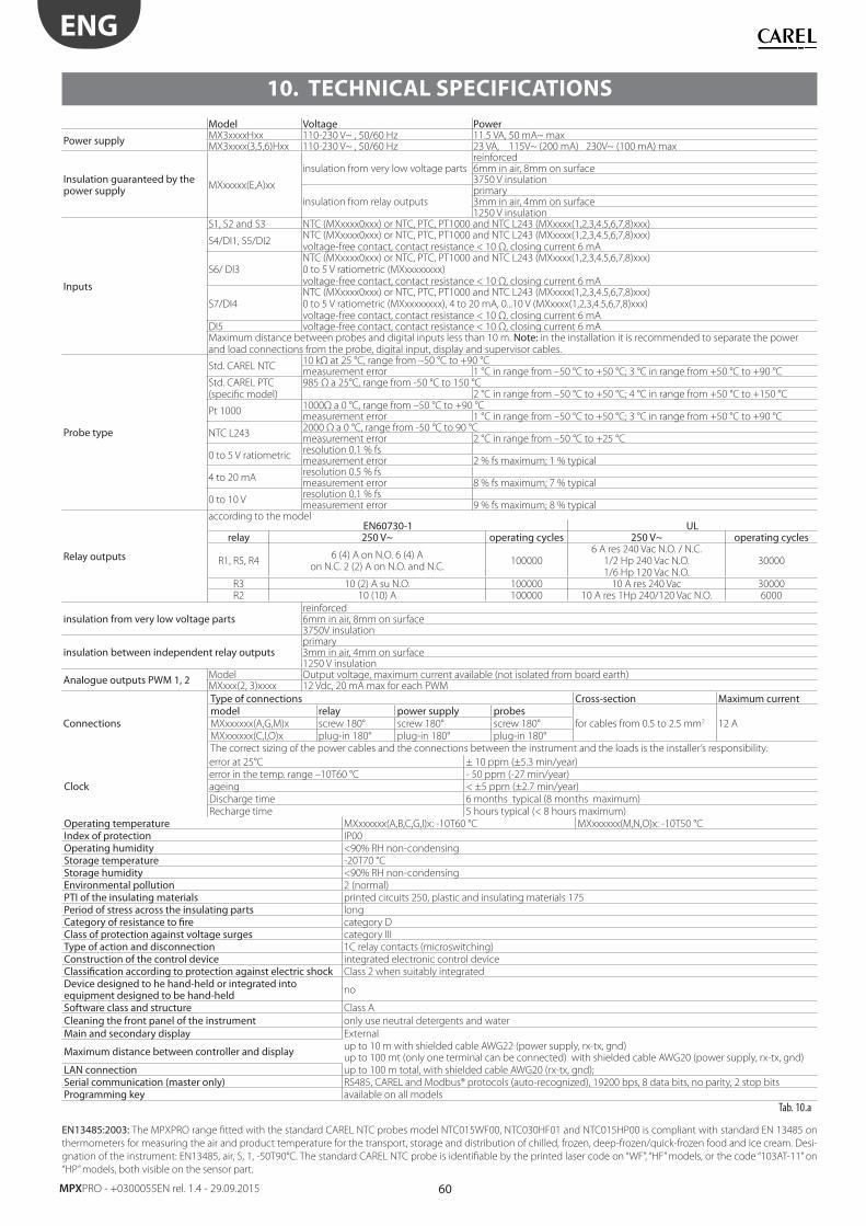
60
ENG
MPXPRO - +0300055EN rel. 1.4 - 29.09.2015
10. TECHNICAL SPECIFICATIONS
Model Voltage Power
Power supply MX3xxxxHxx 110-230 V~ , 50/60 Hz 11.5 VA, 50 mA~ maxMX3xxxx(3,5,6)Hxx 110-230 V~ , 50/60 Hz 23 VA, 115V~ (200 mA) 230V~ (100 mA) max
Insulation guaranteed by the power supply MXxxxxx(E,A)xx
insulation from very low voltage partsreinforced6mm in air, 8mm on surface3750 V insulation
insulation from relay outputsprimary3mm in air, 4mm on surface1250 V insulation
Inputs
S1, S2 and S3 NTC (MXxxxx0xxx) or NTC, PTC, PT1000 and NTC L243 (MXxxxx(1,2,3,4.5,6,7,8)xxx)
S4/DI1, S5/DI2NTC (MXxxxx0xxx) or NTC, PTC, PT1000 and NTC L243 (MXxxxx(1,2,3,4.5,6,7,8)xxx)voltage-free contact, contact resistance < 10 Ω, closing current 6 mA
S6/ DI3NTC (MXxxxx0xxx) or NTC, PTC, PT1000 and NTC L243 (MXxxxx(1,2,3,4.5,6,7,8)xxx)0 to 5 V ratiometric (MXxxxxxxxx)voltage-free contact, contact resistance < 10 Ω, closing current 6 mA
S7/DI4NTC (MXxxxx0xxx) or NTC, PTC, PT1000 and NTC L243 (MXxxxx(1,2,3,4.5,6,7,8)xxx)0 to 5 V ratiometric (MXxxxxxxxx), 4 to 20 mA, 0...10 V (MXxxxx(1,2,3,4.5,6,7,8)xxx)voltage-free contact, contact resistance < 10 Ω, closing current 6 mA
DI5 voltage-free contact, contact resistance < 10 Ω, closing current 6 mAMaximum distance between probes and digital inputs less than 10 m. Note: in the installation it is recommended to separate the power and load connections from the probe, digital input, display and supervisor cables.
Probe type
Std. CAREL NTC10 kΩ at 25 °C, range from –50 °C to +90 °Cmeasurement error 1 °C in range from –50 °C to +50 °C; 3 °C in range from +50 °C to +90 °C
Std. CAREL PTC (specifi c model)
985 Ω a 25°C, range from -50 °C to 150 °C2 °C in range from –50 °C to +50 °C; 4 °C in range from +50 °C to +150 °C
Pt 10001000Ω a 0 °C, range from –50 °C to +90 °Cmeasurement error 1 °C in range from –50 °C to +50 °C; 3 °C in range from +50 °C to +90 °C
NTC L2432000 Ω a 0 °C, range from -50 °C to 90 °Cmeasurement error 2 °C in range from –50 °C to +25 °C
0 to 5 V ratiometricresolution 0.1 % fsmeasurement error 2 % fs maximum; 1 % typical
4 to 20 mAresolution 0.5 % fsmeasurement error 8 % fs maximum; 7 % typical
0 to 10 Vresolution 0.1 % fsmeasurement error 9 % fs maximum; 8 % typical
Relay outputs
according to the modelEN60730-1 UL
relay 250 V~ operating cycles 250 V~ operating cycles
R1, R5, R46 (4) A on N.O. 6 (4) A
on N.C. 2 (2) A on N.O. and N.C.100000
6 A res 240 Vac N.O. / N.C.1/2 Hp 240 Vac N.O. 1/6 Hp 120 Vac N.O.
30000
R3 10 (2) A su N.O. 100000 10 A res 240 Vac 30000R2 10 (10) A 100000 10 A res 1Hp 240/120 Vac N.O. 6000
insulation from very low voltage partsreinforced6mm in air, 8mm on surface3750V insulation
insulation between independent relay outputsprimary3mm in air, 4mm on surface1250 V insulation
Analogue outputs PWM 1, 2 Model Output voltage, maximum current available (not isolated from board earth)MXxxx(2, 3)xxxx 12 Vdc, 20 mA max for each PWM
Connections
Type of connections Cross-section Maximum currentmodel relay power supply probes
for cables from 0.5 to 2.5 mm2 12 AMXxxxxxx(A,G,M)x screw 180° screw 180° screw 180°
MXxxxxxx(C,I,O)x plug-in 180° plug-in 180° plug-in 180°
The correct sizing of the power cables and the connections between the instrument and the loads is the installer’s responsibility.
Clock
error at 25°C ± 10 ppm (±5.3 min/year)
error in the temp. range –10T60 °C - 50 ppm (-27 min/year)
ageing < ±5 ppm (±2.7 min/year)
Discharge time 6 months typical (8 months maximum)
Recharge time 5 hours typical (< 8 hours maximum)
Operating temperature MXxxxxxx(A,B,C,G,I)x: -10T60 °C MXxxxxxx(M,N,O)x: -10T50 °C
Index of protection IP00
Operating humidity <90% RH non-condensing
Storage temperature -20T70 °C
Storage humidity <90% RH non-condensing
Environmental pollution 2 (normal)
PTI of the insulating materials printed circuits 250, plastic and insulating materials 175
Period of stress across the insulating parts long
Category of resistance to fi re category D
Class of protection against voltage surges category III
Type of action and disconnection 1C relay contacts (microswitching)
Construction of the control device integrated electronic control device
Classifi cation according to protection against electric shock Class 2 when suitably integrated
Device designed to he hand-held or integrated into equipment designed to be hand-held no
Software class and structure Class A
Cleaning the front panel of the instrument only use neutral detergents and water
Main and secondary display External
Maximum distance between controller and display up to 10 m with shielded cable AWG22 (power supply, rx-tx, gnd)up to 100 mt (only one terminal can be connected) with shielded cable AWG20 (power supply, rx-tx, gnd)
LAN connection up to 100 m total, with shielded cable AWG20 (rx-tx, gnd);
Serial communication (master only) RS485, CAREL and Modbus® protocols (auto-recognized), 19200 bps, 8 data bits, no parity, 2 stop bits
Programming key available on all models
Tab. 10.a
EN13485:2003: The MPXPRO range fi tted with the standard CAREL NTC probes model NTC015WF00, NTC030HF01 and NTC015HP00 is compliant with standard EN 13485 on
thermometers for measuring the air and product temperature for the transport, storage and distribution of chilled, frozen, deep-frozen/quick-frozen food and ice cream. Desi-
gnation of the instrument: EN13485, air, S, 1, -50T90°C. The standard CAREL NTC probe is identifi able by the printed laser code on “WF”, “HF” models, or the code “103AT-11” on
“HP” models, both visible on the sensor part.
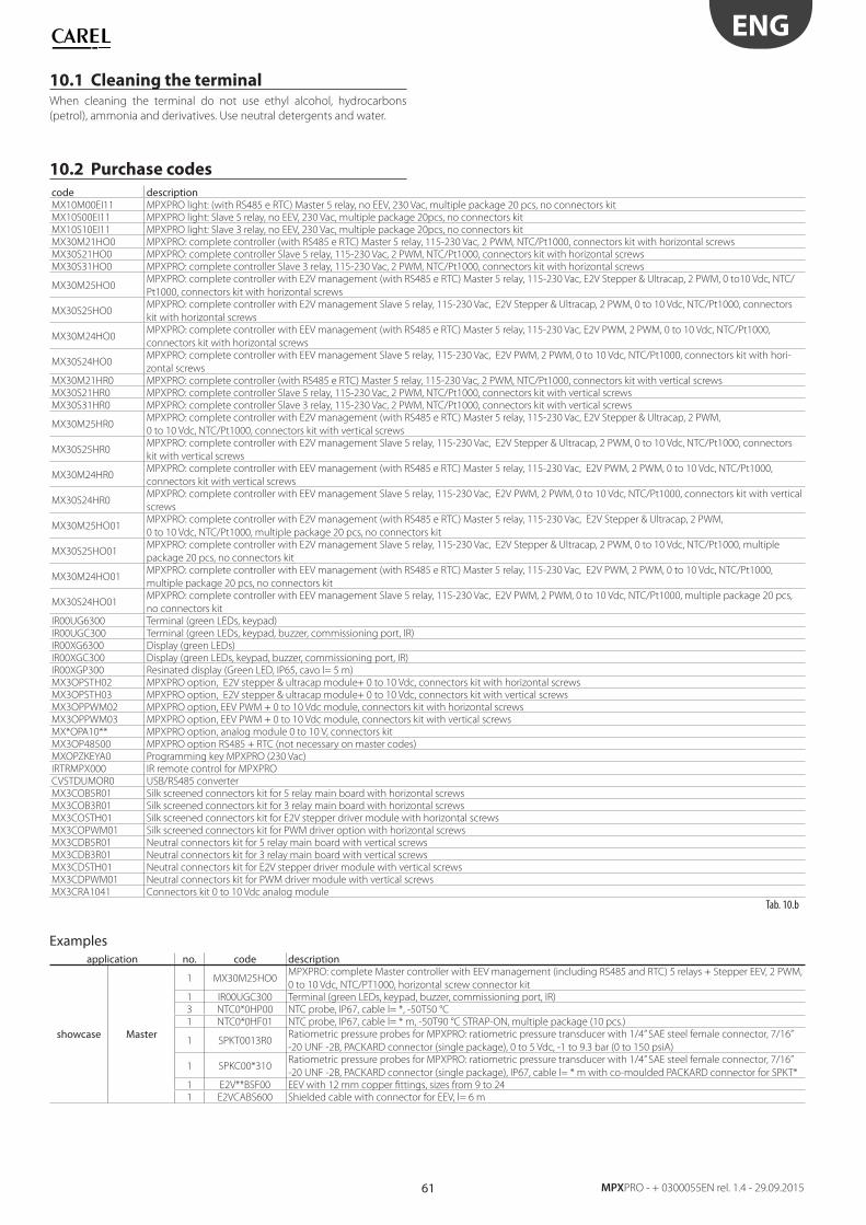
61
ENG
MPXPRO - + 0300055EN rel. 1.4 - 29.09.2015
10.1 Cleaning the terminalWhen cleaning the terminal do not use ethyl alcohol, hydrocarbons
(petrol), ammonia and derivatives. Use neutral detergents and water.
10.2 Purchase codes
code descriptionMX10M00EI11 MPXPRO light: (with RS485 e RTC) Master 5 relay, no EEV, 230 Vac, multiple package 20 pcs, no connectors kit
MX10S00EI11 MPXPRO light: Slave 5 relay, no EEV, 230 Vac, multiple package 20pcs, no connectors kit
MX10S10EI11 MPXPRO light: Slave 3 relay, no EEV, 230 Vac, multiple package 20pcs, no connectors kit
MX30M21HO0 MPXPRO: complete controller (with RS485 e RTC) Master 5 relay, 115-230 Vac, 2 PWM, NTC/Pt1000, connectors kit with horizontal screws
MX30S21HO0 MPXPRO: complete controller Slave 5 relay, 115-230 Vac, 2 PWM, NTC/Pt1000, connectors kit with horizontal screws
MX30S31HO0 MPXPRO: complete controller Slave 3 relay, 115-230 Vac, 2 PWM, NTC/Pt1000, connectors kit with horizontal screws
MX30M25HO0MPXPRO: complete controller with E2V management (with RS485 e RTC) Master 5 relay, 115-230 Vac, E2V Stepper & Ultracap, 2 PWM, 0 to10 Vdc, NTC/
Pt1000, connectors kit with horizontal screws
MX30S25HO0MPXPRO: complete controller with E2V management Slave 5 relay, 115-230 Vac, E2V Stepper & Ultracap, 2 PWM, 0 to 10 Vdc, NTC/Pt1000, connectors
kit with horizontal screws
MX30M24HO0MPXPRO: complete controller with EEV management (with RS485 e RTC) Master 5 relay, 115-230 Vac, E2V PWM, 2 PWM, 0 to 10 Vdc, NTC/Pt1000,
connectors kit with horizontal screws
MX30S24HO0MPXPRO: complete controller with EEV management Slave 5 relay, 115-230 Vac, E2V PWM, 2 PWM, 0 to 10 Vdc, NTC/Pt1000, connectors kit with hori-
zontal screws
MX30M21HR0 MPXPRO: complete controller (with RS485 e RTC) Master 5 relay, 115-230 Vac, 2 PWM, NTC/Pt1000, connectors kit with vertical screws
MX30S21HR0 MPXPRO: complete controller Slave 5 relay, 115-230 Vac, 2 PWM, NTC/Pt1000, connectors kit with vertical screws
MX30S31HR0 MPXPRO: complete controller Slave 3 relay, 115-230 Vac, 2 PWM, NTC/Pt1000, connectors kit with vertical screws
MX30M25HR0MPXPRO: complete controller with E2V management (with RS485 e RTC) Master 5 relay, 115-230 Vac, E2V Stepper & Ultracap, 2 PWM,
0 to 10 Vdc, NTC/Pt1000, connectors kit with vertical screws
MX30S25HR0MPXPRO: complete controller with E2V management Slave 5 relay, 115-230 Vac, E2V Stepper & Ultracap, 2 PWM, 0 to 10 Vdc, NTC/Pt1000, connectors
kit with vertical screws
MX30M24HR0MPXPRO: complete controller with EEV management (with RS485 e RTC) Master 5 relay, 115-230 Vac, E2V PWM, 2 PWM, 0 to 10 Vdc, NTC/Pt1000,
connectors kit with vertical screws
MX30S24HR0MPXPRO: complete controller with EEV management Slave 5 relay, 115-230 Vac, E2V PWM, 2 PWM, 0 to 10 Vdc, NTC/Pt1000, connectors kit with vertical
screws
MX30M25HO01MPXPRO: complete controller with E2V management (with RS485 e RTC) Master 5 relay, 115-230 Vac, E2V Stepper & Ultracap, 2 PWM,
0 to 10 Vdc, NTC/Pt1000, multiple package 20 pcs, no connectors kit
MX30S25HO01MPXPRO: complete controller with E2V management Slave 5 relay, 115-230 Vac, E2V Stepper & Ultracap, 2 PWM, 0 to 10 Vdc, NTC/Pt1000, multiple
package 20 pcs, no connectors kit
MX30M24HO01MPXPRO: complete controller with EEV management (with RS485 e RTC) Master 5 relay, 115-230 Vac, E2V PWM, 2 PWM, 0 to 10 Vdc, NTC/Pt1000,
multiple package 20 pcs, no connectors kit
MX30S24HO01MPXPRO: complete controller with EEV management Slave 5 relay, 115-230 Vac, E2V PWM, 2 PWM, 0 to 10 Vdc, NTC/Pt1000, multiple package 20 pcs,
no connectors kit
IR00UG6300 Terminal (green LEDs, keypad)
IR00UGC300 Terminal (green LEDs, keypad, buzzer, commissioning port, IR)
IR00XG6300 Display (green LEDs)
IR00XGC300 Display (green LEDs, keypad, buzzer, commissioning port, IR)
IR00XGP300 Resinated display (Green LED, IP65, cavo l= 5 m)
MX3OPSTH02 MPXPRO option, E2V stepper & ultracap module+ 0 to 10 Vdc, connectors kit with horizontal screws
MX3OPSTH03 MPXPRO option, E2V stepper & ultracap module+ 0 to 10 Vdc, connectors kit with vertical screws
MX3OPPWM02 MPXPRO option, EEV PWM + 0 to 10 Vdc module, connectors kit with horizontal screws
MX3OPPWM03 MPXPRO option, EEV PWM + 0 to 10 Vdc module, connectors kit with vertical screws
MX*OPA10** MPXPRO option, analog module 0 to 10 V, connectors kit
MX3OP48500 MPXPRO option RS485 + RTC (not necessary on master codes)
MXOPZKEYA0 Programming key MPXPRO (230 Vac)
IRTRMPX000 IR remote control for MPXPRO
CVSTDUMOR0 USB/RS485 converter
MX3COB5R01 Silk screened connectors kit for 5 relay main board with horizontal screws
MX3COB3R01 Silk screened connectors kit for 3 relay main board with horizontal screws
MX3COSTH01 Silk screened connectors kit for E2V stepper driver module with horizontal screws
MX3COPWM01 Silk screened connectors kit for PWM driver option with horizontal screws
MX3CDB5R01 Neutral connectors kit for 5 relay main board with vertical screws
MX3CDB3R01 Neutral connectors kit for 3 relay main board with vertical screws
MX3CDSTH01 Neutral connectors kit for E2V stepper driver module with vertical screws
MX3CDPWM01 Neutral connectors kit for PWM driver module with vertical screws
MX3CRA1041 Connectors kit 0 to 10 Vdc analog module
Tab. 10.b
Examplesapplication no. code description
showcase Master
1 MX30M25HO0MPXPRO: complete Master controller with EEV management (including RS485 and RTC) 5 relays + Stepper EEV, 2 PWM,
0 to 10 Vdc, NTC/PT1000, horizontal screw connector kit
1 IR00UGC300 Terminal (green LEDs, keypad, buzzer, commissioning port, IR)
3 NTC0*0HP00 NTC probe, IP67, cable l= *, -50T50 °C
1 NTC0*0HF01 NTC probe, IP67, cable l= * m, -50T90 °C STRAP-ON, multiple package (10 pcs.)
1 SPKT0013R0Ratiometric pressure probes for MPXPRO: ratiometric pressure transducer with 1/4” SAE steel female connector, 7/16”
-20 UNF -2B, PACKARD connector (single package), 0 to 5 Vdc, -1 to 9.3 bar (0 to 150 psiA)
1 SPKC00*310Ratiometric pressure probes for MPXPRO: ratiometric pressure transducer with 1/4” SAE steel female connector, 7/16”
-20 UNF -2B, PACKARD connector (single package), IP67, cable l= * m with co-moulded PACKARD connector for SPKT*
1 E2V**BSF00 EEV with 12 mm copper fi ttings, sizes from 9 to 24
1 E2VCABS600 Shielded cable with connector for EEV, l= 6 m
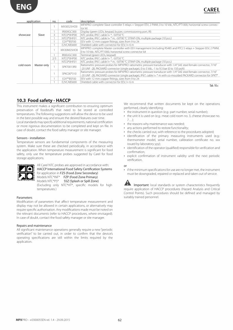
62
ENG
MPXPRO - +0300055EN rel. 1.4 - 29.09.2015
application no. code description
showcase Slave
1 MX30S25HO0MPXPRO: complete Slave controller 5 relays + Stepper EEV, 2 PWM, 0 to 10 Vdc, NTC/PT1000, horizontal screw connec-
tor kit
1 IR00XGC300 Display (green LEDs, keypad, buzzer, commissioning port, IR)
3 NTC0*0HP00 NTC probe, IP67, cable l= *, -50T50 °C
1 NTC0*0HF01 NTC probe, IP67, cable l= * m, -50T90 °C STRAP-ON, multiple package (10 pcs.)
1 E2V**BSF00 EEV with 12 mm copper fi ttings, sizes from 9 to 24
1 E2VCABS600 Shielded cable with connector for EEV, l= 6 m
cold room Master only
1 MX30M25HO0MPXPRO: complete Master controller with EEV management (including RS485 and RTC) 5 relays + Stepper EEV, 2 PWM,
0 to 10 Vdc, NTC/PT1000, horizontal screw connector kit
1 IR00UGC300 Terminal (green LEDs, keypad)
2/3 NTC0*0HP00 NTC probe, IP67, cable l= *, -50T50 °C
1 NTC0*0HF01 NTC probe, IP67, cable l= * m, -50T90 °C STRAP-ON, multiple package (10 pcs.)
1 SPKT0013R0Ratiometric pressure probes for MPXPRO: ratiometric pressure transducer with 1/4” SAE steel female connector, 7/16”
-20 UNF -2B, PACKARD connector (single package), 0 to 5 Vdc, -1 to 9.3 bar (0 to 150 psiA)
1 SPKC00*310Ratiometric pressure probes for MPXPRO: ratiometric pressure transducer with 1/4” SAE steel female connector, 7/16”
-20 UNF -2B, PACKARD connector (single package), IP67, cable l= * m with co-moulded PACKARD connector for SPKT*
1 E2V**BSF00 EEV with 12 mm copper fi ttings, sizes from 9 to 24
1 E2VCABS600 Shielded cable with connector for EEV, l= 6 m
Tab. 10.c
10.3 Food safety - HACCP This instrument makes a signifi cant contribution to ensuring optimum
preservation of foodstuff s that need to be stored at controlled
temperatures. The following suggestions will allow the device to be used
in the best possible way and ensure the desired features over time.
Local standards may specify additional requirements, national certifi cation
or more rigorous documentation to be completed and kept on fi le. In
case of doubt, contact the food safety manager or site manager.
Sensors - installationTemperature sensors are fundamental components of the measuring
system. Make sure these are checked periodically, in accordance with
the application. When temperature measurement is signifi cant for food
safety, only use the temperature probes suggested by Carel for food
storage applications.
All Carel NTC probes are approved in accordance with:
HACCP International Food Safety Certifi cation Systems for application in FZS (Food Zone Secondary)Models NTC*INF* FZP (Food Zone Primary)Models NTC*PS* SSZ (Splash or Spill Zone)(Excluding only NTC*HT*, specifi c models for high
temperatures )
ParametersModifi cation of parameters that aff ect temperature measurement and
display may not be allowed in certain applications, or alternatively may
require specifi c authorisation. Any modifi cations made must be noted on
the relevant documents (refer to HACCP procedures, where envisaged).
In case of doubt, contact the food safety manager or site manager.
Repairs and maintenanceAll signifi cant maintenance operations generally require a new “periodic
verifi cation” to be carried out, in order to confi rm that the device’s
operating specifi cations are still within the limits required by the
application.
We recommend that written documents be kept on the operations
performed, clearly identifying:
• the instrument in question (e.g.: part number, serial number);
• the unit it is used on (e.g.: meat cold room no. 3, cheese showcase no.
7…);
• the reasons why maintenance was needed;
• any actions performed to restore functionality;
• the checks carried out, with reference to the procedures adopted;
• identifi cation of the primary measuring instruments used (e.g.:
thermometer model, serial number, calibration certifi cate no. xxx
issued by laboratory yyy);
• identifi cation of the operator (qualifi ed) responsible for verifi cation and
confi rmation;
• explicit confi rmation of instrument validity until the next periodic
verifi cation.
or• if the minimum specifi cations for use are no longer met, the instrument
must be downgraded, repaired or replaced and taken out of service.
Important: local standards or system characteristics frequently
require application of HACCP procedures (Hazard Analysis and Critical
Control Points). Such procedures should be defi ned and managed by
suitably trained personnel.


CAREL INDUSTRIES - Headquarters
Via dell’Industria, 11 - 35020 Brugine - Padova (Italy)Tel. (+39) 049.9716611 - Fax (+39) 049.9716600e-mail: [email protected] - www.carel.com
Agenzia / Agency:
Recommended